KR930001548B1 - Passive ranging method and apparatus - Google Patents
Passive ranging method and apparatus Download PDFInfo
- Publication number
- KR930001548B1 KR930001548B1 KR1019870001580A KR870001580A KR930001548B1 KR 930001548 B1 KR930001548 B1 KR 930001548B1 KR 1019870001580 A KR1019870001580 A KR 1019870001580A KR 870001580 A KR870001580 A KR 870001580A KR 930001548 B1 KR930001548 B1 KR 930001548B1
- Authority
- KR
- South Korea
- Prior art keywords
- points
- signal
- emitter
- platform
- lbi
- Prior art date
Links
Images


Classifications
-
- G—PHYSICS
- G01—MEASURING; TESTING
- G01S—RADIO DIRECTION-FINDING; RADIO NAVIGATION; DETERMINING DISTANCE OR VELOCITY BY USE OF RADIO WAVES; LOCATING OR PRESENCE-DETECTING BY USE OF THE REFLECTION OR RERADIATION OF RADIO WAVES; ANALOGOUS ARRANGEMENTS USING OTHER WAVES
- G01S5/00—Position-fixing by co-ordinating two or more direction or position line determinations; Position-fixing by co-ordinating two or more distance determinations
- G01S5/02—Position-fixing by co-ordinating two or more direction or position line determinations; Position-fixing by co-ordinating two or more distance determinations using radio waves
- G01S5/04—Position of source determined by a plurality of spaced direction-finders
-
- G—PHYSICS
- G01—MEASURING; TESTING
- G01S—RADIO DIRECTION-FINDING; RADIO NAVIGATION; DETERMINING DISTANCE OR VELOCITY BY USE OF RADIO WAVES; LOCATING OR PRESENCE-DETECTING BY USE OF THE REFLECTION OR RERADIATION OF RADIO WAVES; ANALOGOUS ARRANGEMENTS USING OTHER WAVES
- G01S11/00—Systems for determining distance or velocity not using reflection or reradiation
- G01S11/02—Systems for determining distance or velocity not using reflection or reradiation using radio waves
- G01S11/04—Systems for determining distance or velocity not using reflection or reradiation using radio waves using angle measurements
-
- G—PHYSICS
- G01—MEASURING; TESTING
- G01S—RADIO DIRECTION-FINDING; RADIO NAVIGATION; DETERMINING DISTANCE OR VELOCITY BY USE OF RADIO WAVES; LOCATING OR PRESENCE-DETECTING BY USE OF THE REFLECTION OR RERADIATION OF RADIO WAVES; ANALOGOUS ARRANGEMENTS USING OTHER WAVES
- G01S3/00—Direction-finders for determining the direction from which infrasonic, sonic, ultrasonic, or electromagnetic waves, or particle emission, not having a directional significance, are being received
- G01S3/02—Direction-finders for determining the direction from which infrasonic, sonic, ultrasonic, or electromagnetic waves, or particle emission, not having a directional significance, are being received using radio waves
- G01S3/14—Systems for determining direction or deviation from predetermined direction
- G01S3/46—Systems for determining direction or deviation from predetermined direction using antennas spaced apart and measuring phase or time difference between signals therefrom, i.e. path-difference systems
- G01S3/48—Systems for determining direction or deviation from predetermined direction using antennas spaced apart and measuring phase or time difference between signals therefrom, i.e. path-difference systems the waves arriving at the antennas being continuous or intermittent and the phase difference of signals derived therefrom being measured
Abstract
내용 없음.No content.
Description
제1도는 수동식으로 거리를 탐지하는 두 지점에 수반된 기하학적 관계를 예시한 도면.1 illustrates the geometric relationship involved in two points of manually detecting distance.
제2도는 간섭계 기술에 수반되는 기하학적 관계를 예시한 도면.2 illustrates the geometric relationships involved in interferometer technology.
제3도는 본 발명이 더욱 일반적인 두 지점 거리 탐지 방법의 기하하적 관계를 예시한 도면.3 illustrates the geometric relationship of a two point distance detection method in which the invention is more general.
제4도는 Cartesian거리 및 각도로 변환됨에 따른 본 발명의 경사 거리와 에미터 DOA 측정치간의 기하학적 관계를 예시한 도면.4 illustrates the geometric relationship between the tilt distance and emitter DOA measurements of the present invention as converted to Cartesian distance and angle.
제5도는 시험 비행된 SBI/LBI 시스템의 예에 대한 기능 블록도.5 is a functional block diagram of an example of a test-flighted SBI / LBI system.
제6도는 SBI/LBI 시스템의 예에서 유도된 비행 시험의 결과를 알람표로 예시한 도면.FIG. 6 illustrates in an alarm table the results of flight tests derived from an example of an SBI / LBI system.
* 도면의 주요부분에 대한 부호의 설명* Explanation of symbols for main parts of the drawings
1 : 단기선 간섭계(SBI) 배열기 2 : 장기선 간섭계(LBI)배열기1: Short Line Interferometer (SBI) Array 2: Long Line Interferometer (LBI) Array
3 : SBI/RF/IF변환기 4 : LBI RF/IF변환기3: SBI / RF / IF Converter 4: LBI RF / IF Converter
6 : 국부 발진기 9 : 인터페이스 유니트6 local oscillator 9 interface unit
11 : 컴퓨터 14 : 오실로스코프11: computer 14: oscilloscope
본 발명은 일반적으로 수동식 방향과 거리 탐지 방법 및 장치에 관한 것으로, 특히 이동식 플랫포옴에서 고정식 비협동적 에미터까지의 수동식 거리 탐지 방법 및 장치에 관한 것이다.FIELD OF THE INVENTION The present invention generally relates to a passive direction and distance detection method and apparatus, and more particularly to a passive distance detection method and apparatus from a mobile platform to a stationary non-cooperative emitter.
저고도(low altitude)항공기 및 수상선의 생존가능성 및 군사적 효과는 적의 레이다 지향식 방어 무기로부터 도피 및 회피하고, 그것을 진압하고 파괴할 목적으로 그러한 방어무기의 위치를 신속하고 정확하게 찾아내는 능력(즉, 위치선정 능력)에 크게 좌우된다.The viability and military effects of low altitude aircraft and sea vessels are capable of quickly and accurately locating such defensive weapons for the purpose of fleeing and evading from enemy radar-oriented defensive weapons, suppressing and destroying them. Greatly depends on ability).
이동식 플랫포옴으로부터 고정된 지상 기지식 에미터의 수동식 위치 선정 방법이 다양한데, 가장 통상의 기술에는 방위/고도(AZ/EL)방법, 종래의 삼각측량 방법과, 다중 항공기 도달 시간차(TDOA)방법이 있다. 이들 방법은 아울러 도달 방향(DOA)측정치만으로 제공된 기술과, DOA정보 및 거리 정보 양쪽이 제공된 기술로 구분된다.There are a variety of manual positioning methods for fixed ground-based emitters from mobile platforms, the most common of which are azimuth / altitude (AZ / EL) methods, conventional triangulation methods, and multiple aircraft arrival time differences (TDOA) methods. . These methods are further divided into techniques provided with only direction of arrival (DOA) measurements and techniques provided with both DOA information and distance information.
DOS 측정을 위해 현재 사용되는 기술은 진폭 비교 기술이나 위상 간섭 기술을 포함한다. 전자의 기술은 통상 3660°를 카바하고 광대역인 4개의 직교식 안테나로 구성되는데, 이 안테나에는 인접한 안테나들간의 인입 신호들의 진폭 비교로 인해 DOA 정보가 구성된다. 이들은 3°내지 10°의 정확도를 제공한다(1982년 9월호의 Microwave Journal지에서 페이지 59-76에 기재된 A.R.Baron 등에 의한 "수동식방향탐지 및 신호 위치 선정" 참조).Techniques currently used for DOS measurements include amplitude comparison techniques or phase interference techniques. The former technique consists of four orthogonal antennas, typically 3660 ° wide and wide, which comprise DOA information due to the amplitude comparison of incoming signals between adjacent antennas. They offer an accuracy of 3 ° to 10 ° (see “Passive Direction Detection and Signal Positioning” by A.R.Baron et al., Pages 59-76 in the September 1982 Microwave Journal).
위상 간섭 기술(기술중 가장 간단한 형태)은 이동식 플랫포옴상에서 배치되고 공지된 거리만큼 이격된 한쌍의 안테나를 활용하여, 이 안테나쌍에 관련한 각도로 도달하는 평편파는 이 평면파가 통과한 경로 길이의 차이로 인해 안테나쌍중 더 일찍 도달된 한 안테나에 의한 수신된다. 만일 두 안테나로부터의 신호가 처리된다면, 그들의 위상차는 안테나쌍에 관련한 DOA의 간접 측정치를 제공한다. 간섭계의 DOA정확도는 안테나 간격과 방위 및 고도각의 함수이며, 시스템은 0.1 내지 1°RMS의 동작 정확도를 가지고 구성되었다. 2개 이상의 구성 요소를 구비한 간섭계가 또한 당 기술분야에 공지되어 있다.The phase interference technique (the simplest form of the technique) utilizes a pair of antennas placed on a mobile platform and spaced by a known distance, so that the flat wave arriving at an angle relative to the antenna pair is the difference in path length that the plane wave passes through. Is received by one of the antennas reached earlier in the antenna pair. If the signals from the two antennas are processed, their phase difference provides an indirect measure of the DOA relative to the antenna pair. The DOA accuracy of the interferometer is a function of antenna spacing, azimuth and elevation, and the system is constructed with an operating accuracy of 0.1 to 1 ° RMS. Interferometers with two or more components are also known in the art.
에미터 위치 선정 기술에 관한여, TDOA 방법이 가장 정확하나, 이 방법은 단일 에미터에 대해 거리 탐지를 하기 위해서는 다중 플랫포옴(통상 3) 시스템이 요구되는데, 이들 각각의 플랫포옴상의 수신기에서의 도달 시간차는 에미터의 위치를 선정할 플랫포옴의 공지된 위치와 관련하여 측정되고 처리된다. 이 기술은 다중 플랫포옴과 복잡한 거리측정 및 타이밍 장비를 수반하기 때문에, 단일 이동식 플랫포옴 시스템을 위한 적당한 거리탐지 방법이라고 생각되지는 않는다.Regarding the emitter positioning technique, the TDOA method is the most accurate, but this method requires a multiple platform (typically 3) system for distance detection on a single emitter, the time difference of arrival at the receiver on each of these platforms. Is measured and processed in relation to the known location of the platform on which the emitter is to be positioned. Because this technology involves multiple platforms and complex distance measurement and timing equipment, it is not considered a suitable distance detection method for a single mobile platform system.
AZ/EL기술은 신호의 도달 방위 및 고도각과 지상에 관련한 플랫포옴의 고도를 측정함으로써 에미터의 위치를 선정한다. 이어서, 에미터가 또한 지상 레벨에 있다고 가정하여, 경사 거리가 삼각법 관계로부터 계산된다. 거리 에러가 표적 거리 및 고도의 큰 함수이며(다른 모든 것은 동일), 에미터위의 플랫포옴의 큰 고도에서만 더 좋은 정확도를 제공한다. 또한, 중요한 측정 에러 값은 외부 정보가 지형으로 인한 에미터 고도에 관련하여 시스템에 유용하지 않을 경우 발생될 수 있다.AZ / EL technology selects the position of the emitter by measuring the reach direction and elevation of the signal and the elevation of the platform relative to the ground. Then, assuming that the emitter is also at ground level, the tilt distance is calculated from the trigonometric relationship. Distance error is a large function of target distance and altitude (all others are the same), providing better accuracy only at high altitudes of the platform on the emitter. In addition, significant measurement error values can occur when external information is not available to the system in relation to the emitter altitude due to the terrain.
통상의 AZ/EL위치 선정 시스템은 한쌍의 직교식 위상 간섭계를 활용하여 방위 및 고도와 정보를 얻는다.Conventional AZ / EL positioning systems utilize a pair of quadrature phase interferometers to obtain orientation, altitude, and information.
삼각 측량 기술은 플랫포옴이 에미터에 관련한 이동 경로를 통과함에 따라서, 연속 시간에서 이루어진 2가지 이상의 DOA 측정치를 사용하고, 공지된 삼각법 관계를 사용하여 거리를 산정한다.Triangulation techniques use two or more DOA measurements made in continuous time as the platform passes through the path of travel relative to the emitter, and uses known trigonometry relationships to estimate the distance.
삼각 측량 방법은 진폭 비교방법 또는 간섭방법을 사용하여 DOA정보를 측정할 수 있다. 그러나, 간섭방법이 정확도면에서 10대 1정도의 많은 개선을 제공하기 때문에, 증가된 시스템의 복잡성에 따른 경비에도 불구하고 시스템 정확도 요구가 높은 바람직한 방법이 될 수 있다.The triangulation method may measure DOA information using an amplitude comparison method or an interference method. However, since the interference method provides many improvements of about one-to-one in terms of accuracy, it may be a desirable method having high system accuracy requirements despite the cost of increased system complexity.
따라서, 간섭계를 기초로한 AZ/EL방법이나 간섭계를 기초로 한 삼각 측량방법을 사용하는 단일 이동식 플랫포옴용의 극히 정밀한 수동식 거리 탐지 시스템을 단언할 수 있다. 그러나, 양 기술은 실제 응용을 제한하는 어떤 문제를 안고 있다. 우선, 그들은 극히 정확한 항행 정보, 특히 플랫포옴의 비행방향을 필요로 한다. 앞에서 설명된 바와같이, AZ/EL시스템은 플랫포옴 고도 및 에미터 거리에 많이 의존하며, 지형으로 인한 에러에 매우 민감하다. 삼각 측량 방법은 비교적 느리고, 실제 위치 이동폭, 즉 측정치들간의 이동식 플랫포옴의 경로에 의해 에미터에 대(對)한 각도에 의존한다. 또한, 삼각 측량 방법은 작은 인터셉트 각도, 즉 간섭계의 가시내경에 관련한 큰 각도에서 비효율적이고 비정확하다. 끝으로, 삼각 측량 방법은 수초동안 시스템이 에미터 신호상의 데이터를 모을 수 있기를 요구하기 때문에, 그 수행력이 간헐 신호(에미터가 스캐닝하는 경우)에 의해 저하되거나, 또는 산악 지형의 저 플랫포옴 고도에서 신호 인터셉트가 산발적으로 발생할수도 있기 때문에, 시스템의 효율이 감소된다.Therefore, it is possible to assert an extremely precise manual distance detection system for a single mobile platform using the AZ / EL method based on the interferometer or the triangulation method based on the interferometer. However, both techniques have some problems that limit their practical application. First of all, they need extremely accurate navigation information, especially the direction of flight of the platform. As explained earlier, the AZ / EL system relies heavily on platform elevation and emitter distance and is very sensitive to errors due to terrain. The triangulation method is relatively slow and depends on the actual positional movement width, ie the angle to the emitter by the path of the movable platform between the measurements. In addition, triangulation methods are inefficient and inaccurate at small intercept angles, ie, at large angles relative to the interferometer's visible diameter. Finally, because the triangulation method requires the system to collect data on the emitter signal for several seconds, its performance is degraded by intermittent signals (if the emitter is scanning), or low platform altitudes in mountainous terrain. Because signal intercepts can occur sporadically, the efficiency of the system is reduced.
따라서, 본 발명의 목적은 에미터까지의 거리를 계산하기 위해 수초간격으로 분리된 두가지의 간단한 측정치만을 필요로 하고, 플랫포옴 고도 및/또는 에미터 거리에 의존하지 않으며, 종래의 삼각 측량 방법보다 빠르며, 작은 인터셉트 각도에서 유효하며, 요구되는 플랫포옴의 비행 방향 정확도를 현재의 동작 시스템으로 쉽게 달성되는 레벨까지 감소시키고, 간섭계를 기초로한 시스템의 향상된 정확도를 지닌, 단일 이동식 플랫포옴으로부터 고정식 비협동 에미터까지의 수동식 거리탐지를 하기 위한 방법 및 장치를 제공하는 것이다.Accordingly, the object of the present invention only requires two simple measurements separated by a few seconds to calculate the distance to the emitter, does not depend on platform elevation and / or emitter distance, and is faster than conventional triangulation methods. Fixed non-cooperative emitters from a single mobile platform, effective at small intercept angles, reducing the required flying direction accuracy of the platform to a level easily achieved with current operating systems and with the improved accuracy of an interferometer based system. It is to provide a method and apparatus for the manual distance detection to.
이들 이외의 다른 목적과 장점은 플랫포옴의 경로를 따른 두 지점에서 DOA 각도를 측정하는 완전 분해식 단기선 간섭계(SBI; Short Baseline Interferometer)와, 정밀하지만 매우 불명확한 두지점간의 위상차 변화를 측정하는 차등분해식 장기선 간섭계(LBI; Long Baseline Interferometer)와, 위상 링킹 과정에서 SBI측정치를 이용하므로써 LBI 측정치의 불명확성을 분해하기 위한 컴퓨터를 포함한 신호 처리 수단을 사용하는 기술로 바람직하게 달성된다. 협의의 관점에서 보면, 본 발명은 위상 코드화 신호, 주파수 코드화 또는 랜던 주파수 호프화 신호에 대해서도 기능을 수행할 수 있는 방법 및 장치를 제공한다. 끝으로, 충족된다면, 시스템이 예측 가능하고 형성된 정확도로 수행할 것을 보장하는 에러 형식 및 최적화 기준이 개시된다.Other objectives and advantages other than these include a fully resolved short baseline interferometer (SBI) measuring DOA angle at two points along the path of the platform, and a differential resolution measuring the change in phase difference between two precise but highly inaccurate points. The technique is preferably achieved using a long baseline interferometer (LBI) and a signal processing means including a computer for resolving the ambiguity of the LBI measurement by using the SBI measurement in the phase linking process. In view of consultation, the present invention provides a method and apparatus that can perform functions on a phase coded signal, a frequency coded or a random frequency hop signal. Finally, error formats and optimization criteria are disclosed to ensure that the system performs with predictable and formed accuracy, if satisfied.
본 발명은 간단히 설명한 첨부된 도면을 참조하여 본 발명의 바람직한 실시예에 대한 이하의 상세한 기재로부터 당 기술분야에 숙련된 자들에 의해 더욱 완전하게 이해될 것이다.The invention will be more fully understood by those skilled in the art from the following detailed description of the preferred embodiments of the invention with reference to the accompanying drawings which are briefly described.
제1도에는 모든 단일 플랫포옴의 수동식 거리 탐지 기술에 공통인 이론적 형식의 기초가 되는 기본적인 기하학적 관계가 도시되어 있다. 이동식 플랫포옴은 측변 R1과 R2사이의 꼭지점에 위치한 에미터를 갖는 삼각형의 밑변 L를 통과한다. 사인의 법칙을 사용하면, 에미터까지의 거리 R2는![]()
![]()
각 θ1, θ2의 측정상 에러에 대한 거리 에러 E(R2)의 감도는 이방정식의 도함수를 취하여 얻어진다. 따라서,The sensitivity of the distance error E (R 2 ) to the measurement error of angles θ 1 and θ 2 is obtained by taking the derivative of the anisotropic equation. therefore,

거리 에러 E(R2)는 각도차(θ2-θ1)가 증가함에 따라서 감소하고, 각도차(θ2-θ1)는 측정 지점간의 시간이 증가함에 따라서 증가한다는 것을 전술한 것으로부터 알 수 있다. 따라서, 거리 에러를 최소화하기 위해, 에미터까지의 각도 변화와 이에 따른 거리 탐지 시간의 최대화가 요구된다. 동시에, 거리 탐지 시간을 감소시키기 위한 유일한 방법은 측정치의 정확도를 개선하는 것이다. 앞서의 방정식에서, 첫번째 2개의 항이 분모로 Sin(θ2-θ1)을 갖는 반면에, 세번째 항이 Sin2(θ2-θ1)을 갖는다는 것에 유의해야 한다. 이러한 이유때문에, 측정 각도 변화값의 에러 E(θ2-θ1)가 다른 항보다는 거리 에러에 대해 큰 영향을 준다. 따라서, 측정 각도 변화값의 개선은 a) 주어진 거리 탐지 시간내에 개선된 정확도를 생성하거나, b) 더 짧은 거리 탐지 시간내에 요구된 거리 정확도를 생성하는데 사용될 수 있다.It can be seen from the foregoing that the distance error E (R 2 ) decreases as the angle difference θ 2 -θ 1 increases, and the angle difference θ 2 -θ 1 increases as the time between measurement points increases. Can be. Therefore, in order to minimize the distance error, it is necessary to maximize the angle change to the emitter and thus the distance detection time. At the same time, the only way to reduce the distance detection time is to improve the accuracy of the measurements. In the above equation, it should be noted that the first two terms have Sin (θ 2 -θ 1 ) as the denominator, while the third term has Sin 2 (θ 2 -θ 1 ). For this reason, the error E (θ 2 -θ 1 ) of the measured angle change value has a greater influence on the distance error than the other terms. Thus, the improvement of the measured angle change value can be used to a) produce improved accuracy within a given distance detection time, or b) generate the required distance accuracy within a shorter distance detection time.
제2도에는 길이 D를 갖고, 이동식 플랫포옴의 이동 라인에 대해 각도 α로 놓인 2개 구성 요소의 간섭계가 도시되어 있다. 수신 안테나들 사이의 거리 D가 에미터까지의 거리에 비하여 작아서 인입한 전자기파들이 평면파와 유사하다고 가정한다면, 플랫포옴의 경로에 관련된 각도 θ에서 안테나에 부딪치는 그러한 평면파는 이 파에 의해 카바된 경로 길이의 차이 δ로 인해, 두 안테나중 빨리 도달되는 안테나에 의하여 수신될 것이다. 수신된 신호가 이어서 처리될 경우, 위상차가 발생하며 이것은 도달시간 즉 2π라디안 계수에 비례하여 발생한다.2 shows an interferometer of two components having a length D and positioned at an angle α with respect to the moving line of the movable platform. If the distance D between the receiving antennas is small compared to the distance to the emitter, assuming that the incoming electromagnetic waves are similar to the plane waves, those plane waves that strike the antenna at an angle θ relative to the path of the platform are the path lengths covered by this wave. Due to the difference δ of, it will be received by the one which is reached sooner of the two antennas. When the received signal is subsequently processed, a phase difference occurs, which occurs in proportion to the time of arrival, i.
따라서,![]()
![]()
δ=DSinβ,δ = DSinβ,
여기서 β=(α-θ)-π/2Where β = (α-θ) -π / 2
λ= 신호파장λ = signal wavelength
삼각법으로부터,From trigonometry,
Sinβ=Cos(θ-α).Sinβ = Cos (θ-α).
그러므로,therefore,
![]()
![]()
따라서,![]()
![]()
상기 미분에 의해 신호 도달 각도의 변화 값 dθ에 대하여 위상 변화값 dø를 얻는다. 따라서,By the derivative, the phase change value d? Is obtained with respect to the change value dθ of the signal arrival angle. therefore,
![]()
![]()
![]()
![]()
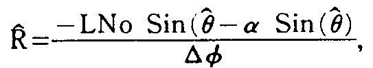
앞서 인용된 거리 방정식을 참조하면 2가지 간섭계 측정치가 플랫포옴의 이동 경로를 따른 두 지점에서 이루어지고 함께 충분히 근접하게 취해져서, 에미터에 관련한 플랫포옴의 각도 위치상의 변화값이 미분으로 표현될 수도 있고, (θ2-θ1) 대신 Δθ로 대체하고, L 대신 V·Δt(V는 측정 지점들간의 플랫포옴의 속도)로 대체한다고 가정하면, 거리 방정식은 더욱 일반적으로Referring to the distance equation cited above, two interferometer measurements are taken at two points along the platform's path of travel and taken close enough together so that the change in the angular position of the platform relative to the emitter may be expressed as a derivative, Assuming that you substitute Δθ instead of (θ 2 -θ 1 ) and V · Δt (V is the velocity of the platform between the measuring points) instead of L, the distance equation is more generally
![]()
![]()
로 쓰여질수 있다.Can be written as:
위상에 관해 도달각의 도함수가 미분에 의해 치환되어 거리에 대한 상기 방정식에서 대체될 경우, 시간에 따른 위상 변화율에 관하여 거리 R을 나타내는 식이 얻어진다. 위치 방정식에 대한 이 위상 속도의 변화 방법은When the derivative of the angle of arrival with respect to the phase is substituted by the derivative and replaced in the above equation for distance, an expression representing the distance R with respect to the rate of phase change over time is obtained. The way this phase velocity changes with respect to the position equation is

로 주어진다.Is given by
이 공식에서, 간섭계의 길이가 에미터에 관련한 플랫포옴 이동으로부터 발생된 위상 변화율을 최대화하도록 임의로 길어질수 있기 때문에, 개선된 정확도가 성취될 수 있다. 그러나, 위상측정치의 고유의 2π 불명확성을 설명하는 것이 고려되지 않는다면, 엄청난 에러가 발생할 수 있다. 이 기술은 통상 장기선 간섭계로 일컬어진다.In this formula, improved accuracy can be achieved because the length of the interferometer can be arbitrarily long to maximize the rate of phase change resulting from the platform movement relative to the emitter. However, if it is not considered to account for the inherent 2 [pi] uncertainty of the phase measurements, a huge error can occur. This technique is commonly referred to as a long line interferometer.
따라서, 단일 장기선 간섭계(LBI)시스템만으로 요구된 정도의 정확도로 거리 탐지 측정을 달성하는 것이 가능하나, 이것은 중요한 시스템 억제 부과한다. 간섭계가 계수 2π까지의 위상만을 측정할수 있기 때문에, +π에서 -π까지의 전이를 관찰하고 설명하기 위해, 위상 측정이 빈번하게 이루어져야 한다. 이러한 빈번한 위상 측정에 대한 필요성이 시스템 성능을 저하시킬 수 있다. 즉 신호가 지형 방해로 인해 차단되거나, 전송이 간헐적이거나 짧을 경우 저하시킬 수 있다. 게다가, 동시에 많은 표적에 대한 거리 탐지를 하고, 새로운 활동 탐색을 할 수 있는 수신기의 능력은 그 수신기의 비활용성으로 인하여 저하될 수 있다.Thus, it is possible to achieve distance detection measurements with the required degree of accuracy with only a single long-line interferometer (LBI) system, but this imposes significant system suppression. Since the interferometer can only measure phases up to a factor of 2π, phase measurements must be made frequently to observe and account for the transition from + π to -π. The need for such frequent phase measurements can degrade system performance. That is, it can be degraded if the signal is blocked due to terrain disturbance or the transmission is intermittent or short. In addition, the receiver's ability to detect distances to many targets at the same time and to search for new activity may be degraded due to the receiver's inactivity.
전술한 것으로부터, 다른 모든 것은 동일하고, 매우 큰 간섭계의 개구, 즉 안테나간의 간격 D를 필요로 하므로써, 주어진 위상 에러 dø에 대해 매우 정밀한 θ측정치를 얻을 수 있음을 또한 알 수 있다. 또한 간섭계는 계수 2π까지 위상차를 측정하기 때문에, 간섭계가 에미터까지의 각도를 측정할 수 있는 최대 시야는![]()
![]()
따라서, 비교적 넓은 시야, 즉 π라디안과 거의 같은 시야를 갖는 간섭계의 경우, 간섭계의 기선 D는 1/2 또는 그 이하의 파장과 거의 같아야 한다. 그러나 전술된 바와 같이 거리 탐지의 정확도는 D값이 큰 경우 최대화된다. 따라서, 간섭계는 정확한 거리 탐지 계산치를 얻을 수 있을 정도로 충분히 긴 기선(D)을 구비한 상태로, 에미터 측정의 필요성간의 단일 간섭계 거리 탐지 시스템내에 장력이 존재하는 반면에, 비교적 넓은 시야를 갖는 시스템에서 측정치간의 위상 링킹을 허용하도록 충분히 이격된 간격에서 명확한 측정치가 이루어질만큼 충분히 짧은 기선을 구비한 간섭계를 갖는 시스템을 아직도 유지한다.Thus, for an interferometer having a relatively wide field of view, i.e., a field of view approximately equal to π radians, the baseline D of the interferometer should be approximately equal to a wavelength of 1/2 or less. However, as described above, the accuracy of the distance detection is maximized when the D value is large. Thus, an interferometer has a baseline D long enough to obtain accurate distance detection calculations, while there is tension in a single interferometer distance detection system between the need for emitter measurements, while a system with a relatively wide field of view. We still maintain a system with an interferometer with a baseline short enough to make clear measurements at well-spaced intervals to allow phase linking between measurements.
이러한 모순은 각 θ1, θ2를 명확하게 측정하는 완전 분해식 SBI와, 에미터까지의 각도 변화(θ2-θ1)을 측정하는 차등분해식 LBI를 병합한 시스템에서 빈번한 LBI위상 측정에 대한 요구없이 측정 지점간의 각도차(θ2-θ1)의 정밀한 측정치를 허용하는 동안 제거될 수 있다는 것을 발견했다. 장기선 간섭계는 극히 정밀하나, 또한 매우 불명확한 측정 기술이다. 그러나, 실제 각도는 아니고 각도 변화만을 측정하는 경우에 이 기술을 사용함으로써, 이 기술의 극도의 정밀도가 활용될 수 있다. 이어서, 위상 링킹이 LBI 측정치로 달성되게끔, SBI 각도 측정치와 LBI측정치를 상호 관련시킴으로써, 불명확도는 허용 가능한 레벨로 감소될 수 있다. SBI를 사용하므로써 지형 방해로 인한 신호의 손실을 수용할 수 있는 해결책을 얻고, 수신기가 시분할되어 다수의 에미터에 대해 동시에 거리 탐지하는데 사용될 수 있을 뿐만 아니라, 주신호 포착 기능을 수행하게 된다. 본 발명의 방법은 위상 링킹을 달성하기 위해 SBI기능과 LBI기능을 합성함으로써, LBI길이 대 SBI길이의 비율에 거의 비례하는 SBI 시스템의 기능에 걸쳐 수동식 거리 탐지의 정확도를 개선시키고, 주어진 시간에서 개선된 정확도 또는 감소된 시간에서 주어진 정확도를 얻도록 응용될 수 있다는 것을 알수 있다.This inconsistency is due to frequent LBI phase measurements in a system that combines a fully resolved SBI that clearly measures angles θ 1 , θ 2 , and a differentially resolved LBI that measures angle changes to the emitter (θ 2 -θ 1 ). It has been found that it can be eliminated while allowing precise measurements of the angular difference (θ 2 -θ 1 ) between the measuring points without the need for it. Long-line interferometers are extremely precise, but also very uncertain measurement techniques. However, by using this technique in the case of measuring only the angular change, not the actual angle, the extreme precision of this technique can be utilized. Then, by correlating the SBI angle measurement with the LBI measurement so that phase linking is achieved with the LBI measurement, the uncertainty can be reduced to an acceptable level. The use of SBI provides a solution that can accommodate the loss of signals due to terrain disturbances, and allows the receiver to be time-divided and used to detect distances simultaneously for multiple emitters, as well as perform main signal capture. The method of the present invention combines the SBI and LBI functions to achieve phase linking, thereby improving the accuracy of manual distance detection over the function of the SBI system, which is almost proportional to the ratio of LBI length to SBI length, and at a given time. It can be appreciated that it can be applied to obtain a given accuracy at a reduced accuracy or a reduced time.
제3도에서 수동식 거리 탐지에 대한 본 발명의 방법의 기본 방정식이 얻어질 수 있는 더욱 일반화된 거리 탐지 시나리오가 도시되어 있다. 이동식 플랫포옴이 에미터에 관하여 임의의 경로를 따라가고, 공지된 관성 항행 시스템으로 얻는 바와 같이 고도, 비행방향, 롤, 피치, 요 및, 시간의 함수로서의 위치를 포함하는 항로 데이터(NAV)를 포착하기 위한 수단으로 갖춰진다고 가정한다. 플랫포옴의 경로를 따라서 시간 T0와 T1의 두 지점에서 측정이 이루어진다고 가정하고, 이 두지점간의 직선 세그먼트 L의 중간 지점에서 거리 탐지 방정식이 유도되는데, 중간지점에서의 직선 세그먼트에 관련하여 거리는 R이고 에미터의 각도 위치는 θ이다. 일단 이들 중간 지점값이 얻어진다면, 이어서 통상의 삼각법 관계가 그들에 응용되어, 공간내의 어느 다른 지점인 현재 플랫포옴 위치로부터의 거리를 계산할 수 있거나, 경도 및 위도 또는 UTM좌표와 같은 지구 기준계로 에미터 위치를 계산할 수 있다.In Figure 3 a more generalized distance detection scenario is shown in which the basic equations of the method of the present invention for passive distance detection can be obtained. The mobile platform follows any path with respect to the emitter and captures route data (NAV), including altitude, direction of flight, roll, pitch, yaw, and position as a function of time, as obtained with known inertial navigation systems. Assume that it is equipped as a means to do so. Assuming that measurements are made at two points along the path of the platform, at time T 0 and T 1 , the distance detection equation is derived at the midpoint of the straight line segment L between these two points. R and the angle position of the emitter is θ. Once these intermediate point values are obtained, then conventional trigonometry relations can be applied to them to calculate the distance from the current platform position, which is any other point in space, or to emitters with a global reference system such as longitude and latitude or UTM coordinates. The position can be calculated.
따라서, 상기 유도된 거리에 대한 삼각법 관계 및 방정식을 사용하여, 완전한 거리 탐지 방법을 정의하는 2개의 방정식이 다음과 같이 표현된다.Thus, using the trigonometric relations and equations for the derived distances, two equations defining the complete distance detection method are expressed as follows.
![]()
![]()
여기서,![]()
![]()
θ0=시간 t=T0에서의 직선 세그먼트에 관련한 에미터의 각도 위치,θ 0 = emitter position of the emitter in relation to the straight line segment at time t = T 0 ,
θ1=시간 t=T1에서의 직선 세그먼트 L에 관련한 에미터의 각도 위치,θ 1 = emitter position of the emitter in relation to the straight line segment L at time t = T 1 ,
![]()
![]()
α=이동식 플랫포옴의 선에 관련한 LBI의 각도 범위,α = angular range of LBI relative to the line of the mobile platform,
N0=신호 사이클내의 플랫포옴의 LBI길이N 0 = LBI length of platform in signal cycle
= 2πD/λ,= 2πD / λ,
Δø= 두 지점 T0와 T1에 선정된 명확한 LBI의 위상차 변화.Δø = Clear phase shift of the LBI selected at two points T 0 and T 1 .
위상 링킹은 두가지 불명확한 LBI 위상 측정치 사이에 발생하는 다수의 2π회전치를 계산함으로써 달성된다. 이 방법은 두가지 SBI 각도를 사용하여 명확한 LBI위상차를 포함한 거리를 예측한다. 시스템내의 에러 예상치를 처리함으로써, 이 거리의 폭이 0.999의 확률로 2π보다 작거나 길게 구성될 수 있다. 이어서, 매우 정밀하나 불명확한 LBI 위상차가 적당한 2π증분으로 참조된다. 예상된 명확한 위상차Δøp(사이클내에서)는Phase linking is accomplished by calculating a number of 2π rotations that occur between two indeterminate LBI phase measurements. This method uses two SBI angles to predict the distance with a clear LBI phase difference. By processing the error estimates in the system, the width of this distance can be configured with a probability of 0.999 or less than 2π. Subsequently, a very precise but unclear LBI phase difference is referenced in the appropriate 2 [pi] increments. The expected clear phase difference Δøp (in cycle) is
![]()
![]()
![]()
![]()
로 주어지는데, 여기서 Δø는 측정된 불명확한 위상차이고, n은 풀어야할 정수이다. 이어서, T0와 T1간의 명확한 위상차 변화값 Δø는![]()
![]()
상기 공식에서, 에미터의 각도 위치 θ0와 θ1은 두지점 T0및 T1에서의 플랫포옴 순간 이동 경로에 관련한 에미터의 산정된 각도 위치, 즉![]()
![]()
여기서, β=플랫포옴의 이동 경로에 관련한 SBI의 각도 위치.Where β = angular position of the SBI relative to the travel path of the platform.
d=SBI의 길이.d = length of SBI.
이어서, 이들 값 및 LBI 위상 측정치가 통상의 Euler 각 변환법을 사용하여 두지점에서 플랫포옴의 롤 및 피치에 대해 보정되어야 한다.These values and LBI phase measurements should then be corrected for the roll and pitch of the platform at two points using conventional Euler angular transformation.
이와 마찬가지로, 두 측정 지점에서의 항공기 비행 방향성의 어떤 차이값은 명확한 위상 변화값으로부터 계산 및 감산되어야 하는 LBI 위상 변화값을 도입할 것이다. 두 지점을 연결하는 직선과, LBI방위각 α와, 제2측정 지점에서의 측정된 SBI 각 θ1에 관련한 두 측정 지점에서의 플랫포옴 비행 방향 각도 H0와 H1의 경우, 차등 비행 방향이 유도된 위상 변화 ΔøH는 다음식으로부터 계산될 수 있다.Likewise, any difference in aircraft flight direction at two measurement points will introduce an LBI phase change that must be calculated and subtracted from the apparent phase change. In the case of the straight line connecting the two points, the LBI azimuth angle α and the platform flight direction angles H 0 and H 1 at the two measuring points in relation to the measured SBI angle θ 1 at the second measuring point, the differential flight direction is derived. phase shift Δø is H can be calculated from the food.
ΔøH=N0[Cos(θ1+α+H1)-Cos(θ1+α+H0)].Δ ° H = N 0 [Cos (θ 1 + α + H 1 ) -Cos (θ 1 + α + H 0 )].
이 공식은 θ0와 θ1을 사용하는 것보다 더 나은 정확도를 얻는다.This formula gives better accuracy than using θ 0 and θ 1 .
직선 세그먼트 L의 중간 지점으로부터 에미터까지의 정밀거리 R이 얻어졌다면, 제2지점 T1에서 플랫포옴으로부터 에미터까지의 정밀거리 R1이 다음식으로부터 쉽게 얻어질 수 있다.The precise distance R to the emitter Reporting obtained from the mid-point of the line segment L, the precision can easily be obtained from the food distance R 1 in the second point T 1 to the emitter from the platform.
![]()
![]()
그러므로, 단일의 이동식 플랫포옴으로부터 고정의 비협동식 레이다 신호인 에미터까지의 바람직한 수동식 거리 탐지방법은 플랫포옴의 경로를 다른 2개의 연속 지점에서 신호의 파장을 측정하는 단계와, SBI로 2개의 지점에서 신호의 명확한 위상차를 측정하는 단계와, LBI로 2개의 저점에서 신호의 불명확한 위상차를 측정하는 단계와, 항행 시스템(NAV)으로 두 지점들에서 그리고 지점들사이에서 플랫포옴의 위치 및 고도를 측정하는 단계와, NAV측정치로부터 두 지점들간의 직선 거리 및 방향을 산정하는 단계와; SBI측정치로부터 두 지점에서 플랫포옴의 순간 이동선에 관련한 에미터의 명확한 각도 위치를 산정하는 단계와; 두 지점에서의 플랫포옴의 롤, 피치 및 요 값에 대해 보정된, 플랫포옴에 관련한 에미터의 산정된 명확한 각도 위치값으로부터 두지점에서 직선 세그먼트에 관련한 에미터의 명확한 각도 위치를 산정하는 단계와; LBI측정치로부터 두 지점간의 신호의 불명확한 위상차의 변화값을 산정하는 단계와, 산정된 각도 위치 및 불명확한 변화값으로부터 두 지점간의 신호의 불명확한 위상차 변화값을 산정하는 단계와; 두 지점에서의 플랫포옴의 롤, 피치 및, 비행 방향값에 대해 보정된, 두 지점간의 신호의 명확한 위상차 변화값을 산정하는 단계와; 측정된 신호파장, 산정된 직선 길이, 두 지점에서 직선 세그먼트에 관련한 에미터의 산정된 각도 위치 및, 두지점에 산정되고 보정된 명확한 위상차 변화값으로부터 직선 세그먼트의 중간 지점에서 에미터까지의 정밀 경사 거리 및 각도 위치를 산정하는 단계와; 제2지점에서 플랫포옴의 에미터까지의 정밀 경사거리 및 각도위치를 사정하는 단계를 포함한다.Therefore, a preferred passive distance detection method from a single mobile platform to an emitter, which is a fixed, non-cooperative radar signal, involves measuring the wavelength of the signal at two different successive points along the path of the platform, and at two points with SBI. Measuring the apparent phase difference of the signal, measuring the unclear phase difference of the signal at two low points with LBI, and measuring the position and altitude of the platform at two points and between points with a navigation system (NAV). Calculating a straight line distance and direction between the two points from the NAV measurement; Calculating a clear angular position of the emitter relative to the teleportation line of the platform at two points from the SBI measurement; Calculating the clear angular position of the emitter relative to the straight line segment at two points from the calculated clear angular position value of the emitter relative to the platform, corrected for the roll, pitch and yaw values of the platform at two points; Calculating a change value of an unclear phase difference of the signal between the two points from the LBI measurement, and calculating an unclear phase difference change value of the signal between the two points from the calculated angular position and the unclear change value; Calculating a clear phase difference change value of the signal between the two points, corrected for the roll, pitch, and flight direction value of the platform at the two points; Precision slope from the midpoint of the straight segment to the emitter from the measured signal wavelength, the estimated straight line length, the estimated angular position of the emitter relative to the straight line segment at two points, and the clear phase difference change calculated and corrected at two points Calculating distance and angular position; Assessing the precise tilt distance and angular position from the second point to the emitter of the platform.
전술한 바람직한 방법의 상술된 방정식들이 선 세그먼트의 중간 지점으로부터 에미터까지의 경사 거리를 산정한다는 것에 주목해야 한다. 이들은 다음의 방정식으로부터 지상의 측정된 플랫포옴 고도 A에 산정된 값들을 보정함으로써 Cartesian거리 Rc 및 θc로 변환될 수 있다.It should be noted that the above-described equations of the preferred method described above calculate the inclination distance from the midpoint of the line segment to the emitter. These can be converted to Cartesian distances Rc and θ c by correcting the values calculated for measured platform elevation A on the ground from the following equation.
![]()
![]()
![]()
![]()
제4도에는 경사 거리![]()
![]()
![]()
![]()
또한, 잡음이 유도된 위상 에러를 다수의 펄스에 대한 관련 매개 변수의 측정치를 평균화함으로써![]()
![]()
따라서, 바람직한 방법의 다른 실시예에서 신호 파장, SBI위상차 및, LBI위상차의 관련 매개변수가 각지점에서 신호의 12개 연속 펄스의 최초 100나노초에 대해 측정되고 및 평균화될 것이다.Thus, in another embodiment of the preferred method, the signal wavelength, SBI phase difference, and related parameters of the LBI phase difference will be measured and averaged over the first 100 nanoseconds of the 12 consecutive pulses of the signal at each point.
거리 방정식을 미분하고 거리로 나눔으로써, 루트-섬 스퀘어(root- sum square)가 거리 에러 백분율을 얻는 이론적 에러 방식이 3개의 주된 에러항을 가지고 유도될 수 있다. 3개의 주된 에러항은 다음과 같다.By differentiating the distance equation and dividing by the distance, a theoretical error scheme in which the root-sum square obtains the distance error percentage can be derived with three main error terms. The three main error terms are:
![]()
![]()
![]()
![]()

여기서, E(S)=SBI RMS 위상 에러, E(L)= LBI RMS위상 에러(진동포함), E(H)=비행방향 에러, λ=파장,![]()
![]()
이 관계는 다음과 같다.This relationship is as follows.
![]()
![]()
여기서, E(ø)=RMS위상 측정 에러(랜덤 성분),![]()
![]()
이 관계가 만족되지 않은 경우, 시스템은 종래의 단일 간섭계 시스템에 잠재적으로 존재하는 총에러와 비슷한 총에러를 생성할 것이며, 따라서 본 발명의 공지된 가장 좋은 형태에 따라 실행되는 수동식 거리 탐지 방법이 상기 관계를 만족시킬 것으로 여겨진다.If this relationship is not satisfied, the system will generate a total error similar to the total error potentially present in a conventional single interferometer system, so that a manual distance detection method implemented according to the best known form of the present invention is It is believed to satisfy the relationship.
본 발명의 주제와 일치하여 시스템의 정확도 및 수행력을 평가하기 위해, 실제의 비행시험 방식이 구성되어 비행 및 시험되었다. 제5도는 9.024인치 길이의 4개의 요소를 갖는 단기선 간섭계 배열기(1)와 제2요소로서 SBI배열기(1)내의 기준 안테나를 사용한 142.44인치 길이의 단일 안테나 LBI배열기(2)를 포함하여 시험 비행된 SBI/LBI시스템의 블록도이다. 이들 각각의 배열기와 함께 SBI RF/IF변환기(3)와 LBI RF/IF변환기(4)가 위치하며, 이들 변환기로부터 하향-변환된 SBI 및 LBI IF신호가 IF처리기(5)에 공급된다.In order to evaluate the accuracy and performance of the system in accordance with the subject matter of the present invention, a real flight test scheme was constructed, flighted and tested. 5 includes a short-
Hewlett Packard 8645B 8-12 GHZ 합성기가 수동식 동조형 국부발진기(6)로서 사용되며 , 분할회로(6a)를 통하여 LO신호를 2개의 RF/IF변환기(3, 4)에 송출한다.A
조종실 디스플레이 유니트(8)를 갖는 상업적 등급의 관성 항향 시스템(NAV)은 초당 8회 측정 비율로 위도, 경도, 롤, 피치 및, 비행방향 정보를 제공하였다. 인터페이스 유니트(9)는 IF처리기(5)에 의해 제공된 펄스 측정치와 NAV(7)로부터의 항로 및 고도 데이터를 완충시키고, 입/출력(I/O)확장 유니트(10)를 통하여 칼라 그래픽 디스플레이(12)를 갖는 디지털 프로세서(11)뿐만 아니라 디지털 자기 테이프 카세트 레코더(13)에 데이터를 전송한다. 오실로스코프(14)는 동조기로서 신호 신호를 모니터링하는데 사용된다.A commercial grade inertial navigation system (NAV) with
인버터 및 전원(15, 16, 17)은 RF/IF변환기(3, 4), NAV(7) 및, 비디오 처리 및/또는 모니터링 장비 각각의 사용에 적당한 전원 형태로 28VDC항공기 전원을 변환시키는데 제공되었다.Inverters and
본 시스템은 Merlin IV항공기에 설치되었다. 따라서, 설치 세부 품목들은 시스템 최적화보다는 유용한 공간 및 편리성을 위한 제품들이었다. SBI안테나 배열기(1)는 통상 기상 레이다를 덮는 보호용 노우즈 레이도움(nose radome)에 설치한다. LBI안테나(2)는 부조종사의 윈도우에 설치된다. SBI(1)는 0°피치에서의 항공기의 중심선에 관하여 28.124°의 각도에서 설치되고, LBI(2)가 6.0°의 피치에서의 항공기 중심선에 관하여 11.2°의 각도에서 설치된다.The system was installed on a Merlin IV aircraft. Therefore, the installation details were more for space and convenience than system optimization. The
컴퓨터(11)는 두가지의 작동방식을 제공하도록 프로그램밍 되었다. 한가지 방식은 실시간 거리 분해를 제공하여, 그 결과를 칼라 디스플레이(12)상에 디스플레이하고, 다른 방식에서는 IF처리기(5) 및 NAV(7)로부터 나온 로오(raw)데이타가 컴퓨터(11)에 의해 얻어지고 내부 자기 디스크 매체상에 기록되었다. 각 시험의 종료시, 데이터가 디스크로부터 자기 테이프 카세트(13)에 카피되고, 디스크 파일이 다음번 시험용 공간을 제공하도록 소거된다. 각 비행의 종료시, 테이프에 기록된 데이터가 지상에서 처리된다.The
SBI/LBI비행시험이 뉴욕, 롱 아일랜드의 비행이 용이한 곳에서 시험거리로 실시되었다. 지상의 진리치는 또한 에미터로서 역할을 하는 나이키 추적 레이다에 의해 제공되었다. 에미터의 특성은 다음과 같다.The SBI / LBI flight test was conducted at a test distance from New York, Long Island where easy flight was possible. Earthly truths were also provided by Nike chase radars that act as emitters. The characteristics of the emitter are as follows.
주파수 : 8.6㎓Frequency: 8.6㎓
PRF : 500PPSPRF: 500PPS
펄스폭 : 0.25마이크로초Pulse Width: 0.25 microseconds
거리정확도 : 12미터Distance accuracy: 12 meters
각도 정확도 : 1.0°Angular Accuracy: 1.0 °
항공 시스템과 추적 레이타 클럭간의 시간 동기화는 항공기상의 컴퓨터 클럭을 세팅하는데 사용되었던 휴대용 밧데리 전원의 시간 표준기를 가지고 달성되었다. 시간, 경사거리, 방위 및 고도각으로 구성된 지상 진리치 데이터는 자기 테이프상에 기록되며, 다음의 값들로 분해가능하였다.Time synchronization between the aviation system and the tracking ray clock was achieved with the time standard of a portable battery power source used to set the computer clock on the aircraft. Ground truth data consisting of time, slope, azimuth and elevation were recorded on a magnetic tape and decomposed into the following values.
시간 : 0.2초Time: 0.2 seconds
거리 : 1야드Distance: 1 yard
각도 : 0.001°Angle: 0.001 °
6가지 비행 시험은 10 내지 50해리(MM) 의 거리, 15 내지 90°의 노우즈를 벗어난 각도 및, 2°/초까지의 전환속도 및 +20°또는 -20°롤의 항공기 동력을 포함한 세가지 다른 궤적을 사용하여 실시되었다.Six flight tests included three different ranges, including a distance of 10 to 50 nautical miles (MM), an angle outside the nose of 15 to 90 °, and a transition speed of up to 2 ° / sec and aircraft power of + 20 ° or -20 ° roll. This was done using trajectories.
사용된 이 세가지 궤적은 "스네이크(snake)", "클로우징(closing)" 및, "크레슨트(crescent)"로 불리워진다. 이 "스네이크"는 사인곡선식으로 변하는 비행방향을 갖는 비행 추적이다. 두가지 스네이크 비행이 2°/초와 1°/초의 전환 속도에서 실시되었다.These three trajectories used are called "snake", "closing", and "crescent". This "snake" is flight tracking with a flight direction that changes sinusoidally. Two snake flights were conducted at 2 ° / sec and 1 ° / sec transition speeds.
"클로우징"궤적은 에미터까지의 단조롭게 변화하는 거리 및 각도를 갖는 거의 직선식 레벨 추적이었다. 하나의 클로우징 궤적이 비행되었다.The "closing" trajectory was a nearly straight level trace with a monotonically varying distance and angle to the emitter. One closing trajectory was flown.
"크레슨트"궤적은 0.5°/초의 일정한 전환속도를 유지함으로써 에미터까지의 거의 일정한 거리에서의 단계적 각도 변화를 제공하도록 구성되었다. 세가지 경우의 크레슨트 궤적이 17 NM, 40NM 및 48.5NM의, 공칭 거리에서 비행되었다.The “crescent” trajectory is configured to provide a stepwise angle change at an almost constant distance to the emitter by maintaining a constant transition rate of 0.5 ° / sec. Three cases of crescent trajectories were flown at nominal distances of 17 NM, 40 NM and 48.5 NM.
각 비행 시험 세그먼트는 컴퓨터(11)디스크 용량에 의해 3분동안으로 제한되었다. 각각의 시험 세그먼트는 세가지 SBI(1)위상, LBI(2)위상 및, 네가지 신호 진폭의 측정치에 항공기의 위도, 경도, 롤, 피치 및 비행방향의 1440개의 측정치를 합한 86,800개의 단펄스를 수집했다. 각 시험의 종료시, 데이터는 자기 테이프에 카피되고, 디스크 공간은 다음 시험을 위해 소거되었다.Each flight test segment was limited to 3 minutes by
지상 처리방법은 2단계로 수행되었다. 제1단계에서, 단 펄스 데이터가 자기 테이프로부터 다시 판독되었고, 펄스 측정 평균치가 계산되었다. 그 다음으로, 위도, 경도, 롤, 피치 및, 비행방향 데이터가 테이프로부터 판독되었고, 펄스 데이터의 도달 시간에 보간(補間)되며, 만일 파일안으로 평균 펄스 데이터와 합쳐진다. 제2처리 단계는 거리 탐지 방정식을 파일내의 데이터에 적용하여 수행 통계를 계산하였다. 끝으로, 측정된 RMS거리 탐지에러는 이론적 에러 방식에 비교되어, 예상 에러의 이론 방식의 정확도를 평가한다.Ground treatment was carried out in two stages. In the first step, short pulse data was read back from the magnetic tape, and the pulse measurement average was calculated. Latitude, longitude, roll, pitch, and flight direction data were then read from the tape, interpolated at the arrival time of the pulse data, and merged with the average pulse data into the file. The second processing step computed performance statistics by applying the distance detection equation to the data in the file. Finally, the measured RMS distance detection error is compared to the theoretical error method to evaluate the accuracy of the theoretical method of the expected error.
LBI/SBL비행 시험의 일람이 제6도의 표로 예시되어 있다. LBI(2)측정 에러를 평가하는데 사용된 런 3을 포함한 두가지 경우를 제외하고는, 13,656거리 측정치에 대한 전체 RMS에러는 실제치가 8.9%였고, 이론치가 8.6%였다. 주파수 스위피(sweep)화, 위상 코드화 및 주파수 호프화 신호들은 그들의 방법상 효과가 이해되고 보상되지 않을 경우 SBI/LBI거리 탐지 정확도를 저하시키리라고 예상된다.A list of LBI / SBL flight tests is illustrated in the table of FIG. Except for two cases, including
이들 효과에 대한 분석은 항공기 중심선으로부터 30°방향인 20.99인치 단기선 간섭계와 항공기 중심선으로부터 15°방향인 204인치 장기선 간섭계를 활용한 또다른 전형적인 시스템에 의하여 실행되었다.Analysis of these effects was performed by another typical system utilizing a 20.99 inch short-line interferometer 30 ° from the centerline and a 204-inch
쌍위상 코드화 쳐프(chirp)신호의 경우에 있어서, SBL와 LBI측정값은 위상 측정값에 유입되는 ±180°위상 "글리치(glitch)"에 의하여 교란된다. 수행효과는 신호에 대한 각도, 비디오 대역폭 및, 위상 측정값의 통합 주기에 의존한다.In the case of a biphasic coded chirp signal, the SBL and LBI measurements are disturbed by a ± 180 ° phase “glitch” introduced into the phase measurement. The performance effect depends on the angle, video bandwidth, and integration period of the phase measurements for the signal.
그러나, 전형적인 시스템의 최악-경우의 분석은 SBI배열기의 경우 0°, LBI배열기의 경우 15°일때가 최악-경우의 각도임을 나타낸다. 0°에서의 신호에 있어서, 위상 글리치의 폭은 1.5나노초인데, 그 이유는 SBI에 대한 경로 길이차가 약 18인치이고 광속은 약 1ft/10-9초이기 때문이다. 35나노초의 상승시간을 갖는 10㎒ 비디오 필터에 의해 180°글리치가 약 7.7°로 감쇠된다. 바람직한 실시예의 100×10-9초에 대하여 글리치가 평균화될 경우, 그 값은 약 0.12°로 감소될 것이며, 따라서 무시해도 좋다.However, worst-case analysis of a typical system indicates that the worst-case angle is 0 ° for SBI arrays and 15 ° for LBI arrays. For signals at 0 °, the width of the phase glitches is 1.5 nanoseconds because the path length difference for SBI is about 18 inches and the luminous flux is about 1 ft / 10 -9 seconds. The 180 ° glitches are attenuated to about 7.7 ° by a 10 MHz video filter with a rise time of 35 nanoseconds. If the glitch is averaged over 100 × 10 −9 seconds of the preferred embodiment, the value will be reduced to about 0.12 ° and can therefore be ignored.
LBI의 경우, 15°의 상대각에 대해, 경로 길이의 차이는 약 15피트이고, 10㎒비디오 필터를 통과하여 100×10-9초에 걸쳐 평균화 후의 그리치는 약 11.14°의 에러를 만들어낸다. 플랫포옴을 약 450NM/hr의 속도로 이동시키고, 두번째 SBI/LBI측정이 10초 뒤에 행하여졌다면, 글리치에 의해 유도된 두번째 측정의 에러는 14.09°가 될 것이다. 위상차의 결과적 에러는 2.95°무시할 수 있다.For LBI, for a relative angle of 15 °, the path length difference is about 15 feet, and Grichch after averaging over 100 × 10 −9 seconds through a 10 MHz video filter produces an error of about 11.14 °. If the platform was moved at a rate of about 450 NM / hr and a second SBI / LBI measurement was made 10 seconds later, the error of the second measurement induced by the glitch would be 14.09 °. The resulting error of the phase difference can be ignored at 2.95 °.
따라서, 방식화된 시스템에 대한 최악인 경우의 시나리오에 있어서, 위상 코드화 신호는 본 발명의 시스템이 무시할 정도의 영향을 줌을 나타낸다. 또한, 유사-랜덤 위상 코드화 신호가 가정될 경우, 바람직한 실시예인 12-펄스 평균 방법이 에러를 더욱 줄인다는 사실을 유의해야 한다. +180°또는 -180°위상 변화가 똑같다고 가정할 때, 상기 언급된 에러는 인자 6으로 또한 감소되는 것을 알 수 있다.Thus, in the worst case scenario for a formulated system, the phase coded signal indicates that the system of the present invention has a negligible effect. It should also be noted that when a pseudo-random phase coded signal is assumed, the 12-pulse averaging method, which is the preferred embodiment, further reduces the error. Assuming that the + 180 ° or -180 ° phase changes are the same, it can be seen that the above mentioned error is also reduced to
주파수 스위프화 신호의 경우, 이들은 SBI/LBI 거리 탐지 수행력에 최소한의 영향을 준다는 것을 알 수 있다. 선형 스위프화 FM의 영향은 두가지 형태의 변칙을 유발시킨다. 그중 하나는 각각의 안테나에서의 위상 측정값의 다양한 주파수에서 산출된다는 것이다. 이것은 바이어스 에러에 영향을 줄 수 있다. 두번째는 매우 긴 기선의 간섭계에서만 나타나는데, 이때 안테나들간의 시간 분리가 주파수 오프셋(offset)을 산출하며, 이로인해 부가된 위상 에러가 발생된다.In the case of frequency swept signals, it can be seen that they have minimal impact on the performance of the SBI / LBI range detection. The effect of linear swept FM causes two types of anomalies. One of them is that it is calculated at various frequencies of the phase measurement at each antenna. This can affect bias errors. The second appears only in very long baseline interferometers, where the time separation between antennas yields a frequency offset, which results in an added phase error.
첫번째 에러의 경우, 본 발명의 전형적인 바람직한 실시예는 상술된 바와같이, 위상 및 주파수 측정값이 펄스의 초기 100×10-9초에 걸쳐 평균된 값임을 예견한다. 측정 경로들이 매칭되므로 평균 위상 측정값을 평균 주파수와 일치하여 거리 탐지 정확도가 감소하지는 않는다.In the case of the first error, a typical preferred embodiment of the present invention predicts that the phase and frequency measurements are averaged over the initial 100 × 10 −9 seconds of the pulse, as described above. Since the measurement paths match, the average phase measurement does not match the average frequency, which does not reduce the distance detection accuracy.
두번째 방식의 에러에 있어서, 수행력은 펄스내의 선형 FM의 기울기에 정비례하여 저하될 것이다. 최악인 경우의 신호가 100㎒의 선형 FM과 1×10⁻⁶초의 펄스폭을 갖는다고 가정하면, 신호의 기울기는 100㎒/1×10-6초가 된다. 안테나 사이의 간격으로 인해, 간섭계는 한 안테나에서 다른 안테나보다 먼저 신호를 수신하는데, 안테나 간격에 따라 시간 지연이 증가된다. 위상 검출기에서 처리된 두개의 채널이 시간(및 주파수)에서 오프셋 되므로, 수행력을 저하시킬 수 있는 위상 오프셋이 발생할 것이다. 주파수 쳐프 위상 오프셋 θc는 다음으로 주어지는데,For the error of the second scheme, the performance will drop in direct proportion to the slope of the linear FM in the pulse. Assuming that the worst case signal has a linear FM of 100 MHz and a pulse width of 1 × 10 −6 seconds, the slope of the signal is 100 MHz / 1 × 10 −6 seconds. Due to the spacing between the antennas, the interferometer receives the signal at one antenna before the other antenna, with increasing time delay depending on the antenna spacing. Since the two channels processed by the phase detector are offset in time (and frequency), a phase offset will occur that can degrade performance. The frequency chirp phase offset θ c is given by
øc=2πDCos(θ+α)·C·쳐프속도·ts øc = 2πDCos (θ + α), C, chirp speed, t s
상기식에서 C=광속,Where C = beam,
ts=측정 기간.t s = measurement period.
상기 예견된 최악인 경우의 기하학에 있어서, 위상 오프셋은 SBI의 경우는 0.09°, LBI의 경우는 1°로서 무시할만 하다. 따라서, 본 발명의 SBI/LBI시스템은 상술된 최악인 경우의 시나리오에 해당하고, 현재 공지된 그 어떤 위협신호의 상황을 능가하는 모든 악 조건하에서 정확하게 기능을 수행하는 것이 예상된다.In the worst case geometry foreseen, the phase offset is negligible as 0.09 ° for SBI and 1 ° for LBI. Therefore, the SBI / LBI system of the present invention corresponds to the worst-case scenario described above, and is expected to function correctly under all evil conditions that surpass any situation of any threat signal currently known.
주파수 민첩 신호의 경우, 넓은 RF의 민첩 범위와 랜덤 펄스 주파수 패턴을 갖는 신호에 대하여 SBL/LBI거리 탐지 능력을 성취하기 위하여서는 두가지 요구 조건이 충족되어야 한다. 첫번째는 상이한 주파수에서 발생하는 펄스들을 정확하게 위상 연결시키는 것이다. 두번째는 연결된 주파수 차이에 의해 야기된 위상 에러를 보정하는 것이다.For frequency agile signals, two requirements must be met to achieve SBL / LBI range detection capability for signals with a wide RF agility range and random pulse frequency patterns. The first is to accurately phase-link the pulses that occur at different frequencies. The second is to compensate for the phase error caused by the connected frequency difference.
이러한 과정을 수용하기 위하여, 하기에서와 같은 바람직한 실시예에 의하여 SBI/LBI데이터 수집 방법에서 변화되어야 한다. 주파수 어자일 레이다가 검출될때, 다수의 펄스 N에 대한 파장과 LBI위상차는 주파수 안정 에미터의 경우에 행하여진 바와같이 일련의 측정값을 평균하는 대신 프로세서내에서 측정되어 기억된다. 두번째 측정이 행하여 졌을때, 이 두가지 방법은 소정의 주파수 범위 ΔF 내에서 펄스쌍을 찾아내는데 사용된다. 특정된 주파수 범위 ΔF내에서 충분히 큰 일련의 펄스쌍을 찾을 경우, 주파수 오프셋 위상 보정은 일단 불명확하게 측정된 LBI위상차에 대하여 행해지고, 그 결과를 평균한 뒤 위상이 연결된다.In order to accommodate this process, the SBI / LBI data collection method should be changed by the preferred embodiment as follows. When a frequency agile radar is detected, the wavelength and LBI phase differences for a number of pulses N are measured and stored in the processor instead of averaging a series of measurements as was done for a frequency stable emitter. When the second measurement is taken, these two methods are used to find the pair of pulses within the predetermined frequency range ΔF. In the case of finding a sufficiently large series of pulse pairs within the specified frequency range ΔF, frequency offset phase correction is performed on the LBI phase difference, once measured indefinitely, and the results are averaged and the phases concatenated.
기억되고 처리된 펄스들의 수 N과 ΔF의 값을 최적화하도록 트레이드오프(trade off)가 이루어져야 한다. 최적화 방법은 LBI에서의 주파수 오프셋 위상 보정에 의한 위상 에러가 에러의 위상 링킹 확률 또는 거리 탐지 정확도를 떨어뜨리지 않을 정도로 충분히 작고, 바람직한 실시예의 평균 범위를 만족시킬 최소한 12개의 펄스 쌍을 찾아낼 확률이 높도록 충분히 큰 ΔF값을 찾는 것이다. 이러한 방법을 성취하기 위하여, 우선 주파수 오프셋 위상 보정에 대한 알고리즘(algorithm)이 유도되어야 하는데, 이러한 유도치는 대처해야 하는 정확도 구속력과 고려중인 특별한 시스템에 관한 에러 특징을 평가하기 위해 취해지고, 이러한 범주내에서 위상 링킹의 높은 확률을 제공하는데 필요한 ΔF의 값과 측정 수 N이 예견된다.A trade off has to be made to optimize the value of the number N and ΔF of the stored and processed pulses. The optimization method is small enough that the phase error due to frequency offset phase correction in the LBI does not degrade the phase linking probability of the error or the accuracy of the distance detection, and the probability of finding at least 12 pulse pairs that will satisfy the average range of the preferred embodiment. Find a ΔF value that is large enough to be high. To achieve this method, an algorithm for frequency offset phase correction must first be derived, which is taken to assess the accuracy constraints that must be coped with and the error characteristics for the particular system under consideration, and within these categories. The value of ΔF and the number N of measurements needed to provide a high probability of phase linking are predicted.
따라서, F2에서 측정된 불명확한 위상값 ø2, 주파수 F1에서 측정된 불명확한 위상값 ø1, SBI각도 측정치 θ 및, LBI방향 α에 대하여 위상 보정이 다음식으로 주어진다 :Thus, the phase correction is given by the following equation for the indefinite phase value ø 2 measured at F 2 , the indeterminate phase value ø 1 measured at frequency F 1 , the SBI angle measurement θ and the LBI direction α:

상기식에서,![]()
![]()
![]()
![]()
상기 식이 유도되고 SBI각도 측정 에러항이 치환된다면 다음의 에러 공식이 된다 :If the equation is derived and the SBI angle measurement error term is substituted, then the error formula is:

방식화되어 시험된 전형적 시스템에 있어서, 주파수 오프셋 보정 에러는 2GHz와, 플랫포옴의 노우즈에서 120°벗어나 곳에서 최대이다. 그러나 이러한 각도에서, SBI각도 측정 에러가 거리 탐지 정확도를 좌우한다. LBI위상 측정 에러에 대하여 거리 탐지 에러가 가장 민감한 작은 82.5°이다. 따라서, 2GHz에서 82.5°이다.In a typical system tested methodically, the frequency offset correction error is maximum at 2 GHz and 120 ° away from the platform's nose. However, at this angle, the SBI angle measurement error governs the distance detection accuracy. The distance detection error is the smallest, most sensitive 82.5 °, for the LBI phase measurement error. Thus, 82.5 ° at 2 GHz.
E(øF2-øF1)=0.005ΔF·E(ø).E (ø F2- ø F1 ) = 0.005 ΔF · E (ø).
상기 방정식은 단펄스 에러를 나타낸다. 그러나, 과정 처리전에 12개의 펄스가 바람직한 실시예에서 평균화된다. 따라서, 주파수의 예측된 랜덤 분배에 따라서, ΔF는 -ΔF에서 +ΔF의 균일한 분배에 따른 랜덤 변수로서 취급될 수 있다. 12개의 펄스를 평균한후 RMS 값은 0.167 ΔF이다. 따라서, 다음과 같이 된다 :The equation represents short pulse error. However, 12 pulses are averaged in the preferred embodiment prior to the process. Thus, depending on the predicted random distribution of frequencies, ΔF may be treated as a random variable with a uniform distribution of −ΔF to + ΔF. After averaging 12 pulses, the RMS value is 0.167 ΔF. Thus, it becomes as follows:
E(øF2-øF1)=0.000837ΔF E(ø).E (ø F2 -ø F1 ) = 0.000837ΔF E (ø).
만일 상기 에러가 랜덤한 LBI위상 측정 에러의 1/4보다 작다면, 위상 링킹 수행력과 거리 탐지 정확도에 무시할만한 영향을 끼친다. 따라서, 바이어스 에러가 10°인 기술된 예시적 시스템에 있어서, ΔF는 약 96㎒보다 작다. 이로인해 바이어스 에러를 0.8로 감소시키는데, 이는 다른 에러에 비하여 무시할만하다.If the error is less than one quarter of the random LBI phase measurement error, it has a negligible effect on phase linking performance and distance detection accuracy. Thus, for the described exemplary system with a bias error of 10 °, ΔF is less than about 96 MHz. This reduces the bias error to 0.8, which is negligible compared to other errors.
트레이드오프내의 잔류 요소는 처리시 최소한 12개의 펄스상을 찾아낼 수 있는 높은 확률을 제공하는데 필요한 측정값의 수를 산출할 수 있게 한다. 250㎒대역폭내의 ΔF에 부합되는 단 펄스쌍의 확률은 다음과 같다 :Residual factors within the tradeoff enable the calculation of the number of measurements needed to provide a high probability of finding at least 12 pulses in the process. The probability of a short pulse pair meeting ΔF in the 250 MHz bandwidth is:
![]()
![]()
NXN검사에서 최소한 12개의 쌍이 발견될 확률은 다음과 같다 :The probability of finding at least 12 pairs in an NXN test is:

다음의 표는 ΔF=96㎒의 경우 P12를 열거한 것이다.The following table lists P 12 for ΔF = 96 MHz.

따라서, 예시적 시스템에 있어서, 확률이 0.998인 12쌍의 매칭인 펄스를 위치설정하기 위하여서는 단지 2개의 부가적 측정값만이 필요하다. 단지 11개의 쌍이 발견될 수 있는 0.2%경우에 있어서, 거리 에러는 1.05인 매우 작은 인자로 증가한다. 2GHZ에서의 충분한 마진이 존재하기 때문에, 위상 링킹에 대한 영향은 없다.Thus, in the exemplary system, only two additional measurements are needed to position a pulse that is 12 pairs of matches with a probability of 0.998. In the 0.2% case where only 11 pairs can be found, the distance error increases with a very small factor of 1.05. Since there is sufficient margin at 2GHZ, there is no effect on phase linking.
본 기술의 숙련자에게 이제 명백해지는 바와같이, 본 발명의 방법의 SBI, LBI거리 탐지 기술은 진동, 다중경로, 랜덤 효과, 항공기 방향조정 및 측정에러등이 존재하는데 상황하에서, 그리고 실질적인 응용분야에서 활용된다. 측정된 비행 시험 결과와 상기 제시된 이론적 에러 방식간에서는 우수한 상관 관계가 있다. 이러한 상관 관계는 에러 방식이 다양한 시스템의 주어진 성능을 예견하기 위한, 또한 모든 공지된 신호 코드화 표적 에미터에 대하여 효과적인 도구임을 확인시킨다. 따라서, 비행 시험예에서 및 상술된 특수 시스템은 본질상 일례로서 고려되어야 하며, 본 발명의 사상과 범위는 첨부된 특허청구의 범위에 의해서만 한정되어야 한다.As will now be apparent to those skilled in the art, the SBI and LBI range detection techniques of the method of the present invention have vibrations, multipaths, random effects, aircraft steering and measurement errors, and are used in situations and in practical applications. do. There is a good correlation between the measured flight test results and the theoretical error scheme presented above. This correlation confirms that the error mode is an effective tool for predicting the given performance of various systems and also for all known signal encoded target emitters. Accordingly, the flight test example and the specific system described above should be considered as an example in nature, and the spirit and scope of the present invention should be limited only by the appended claims.
Claims (18)


Applications Claiming Priority (3)
| Application Number | Priority Date | Filing Date | Title |
|---|---|---|---|
| US833,730 | 1986-02-25 | ||
| US06/833,730 US4734702A (en) | 1986-02-25 | 1986-02-25 | Passive ranging method and apparatus |
| US5833730 | 1986-02-25 |
Publications (2)
| Publication Number | Publication Date |
|---|---|
| KR870008170A KR870008170A (en) | 1987-09-24 |
| KR930001548B1 true KR930001548B1 (en) | 1993-03-04 |
Family
ID=25265128
Family Applications (1)
| Application Number | Title | Priority Date | Filing Date |
|---|---|---|---|
| KR1019870001580A KR930001548B1 (en) | 1986-02-25 | 1987-02-25 | Passive ranging method and apparatus |
Country Status (13)
| Country | Link |
|---|---|
| US (1) | US4734702A (en) |
| EP (1) | EP0237223B1 (en) |
| JP (1) | JP2701025B2 (en) |
| KR (1) | KR930001548B1 (en) |
| AU (1) | AU592510B2 (en) |
| CA (1) | CA1279391C (en) |
| DE (1) | DE3785475T2 (en) |
| DK (1) | DK168342B1 (en) |
| ES (1) | ES2039430T3 (en) |
| IL (1) | IL81607A (en) |
| NO (1) | NO178415C (en) |
| PT (1) | PT84357B (en) |
| TR (1) | TR23894A (en) |
Families Citing this family (57)
| Publication number | Priority date | Publication date | Assignee | Title |
|---|---|---|---|---|
| US7002510B1 (en) * | 1987-01-28 | 2006-02-21 | Raytheon Company | Method and apparatus for air-to-air aircraft ranging |
| NO172518C (en) * | 1987-03-20 | 1993-07-28 | Massachusetts Inst Technology | PROCEDURE FOR DETACHING COUNTRY DATA DESCRIBING SATELLITES |
| IT1241398B (en) * | 1987-09-01 | 1994-01-10 | Thomson Csf | PASSIVE ACOUSTIC TELEMETRY PROCEDURE |
| GB2234876A (en) * | 1989-08-02 | 1991-02-13 | British Aerospace | Attitude determination using direct and reflected radiation. |
| US5270718A (en) * | 1992-08-21 | 1993-12-14 | Technology Service Corporation | Method and apparatus for tracking targets from direct and multipath reflected radar signals |
| US5343212A (en) * | 1992-12-11 | 1994-08-30 | Litton Industries, Inc. | (AOA/LBI) emitter ranging method and apparatus |
| US5870179A (en) * | 1993-06-25 | 1999-02-09 | The Regents Of The University Of Colorado | Apparatus and method for estimating range |
| US5502450A (en) * | 1994-07-19 | 1996-03-26 | E-Systems, Inc. | Single antenna direction-finding system |
| US6911638B2 (en) | 1995-02-03 | 2005-06-28 | The Regents Of The University Of Colorado, A Body Corporate | Wavefront coding zoom lens imaging systems |
| US20020195548A1 (en) * | 2001-06-06 | 2002-12-26 | Dowski Edward Raymond | Wavefront coding interference contrast imaging systems |
| US20020118457A1 (en) * | 2000-12-22 | 2002-08-29 | Dowski Edward Raymond | Wavefront coded imaging systems |
| US7218448B1 (en) | 1997-03-17 | 2007-05-15 | The Regents Of The University Of Colorado | Extended depth of field optical systems |
| US5572220A (en) * | 1995-05-18 | 1996-11-05 | Hughes Aircraft Company | Technique to detect angle of arrival with low ambiguity |
| US5708443A (en) * | 1996-08-07 | 1998-01-13 | Litton Systems Inc. | Method and apparatus for using signal doppler change to resolve long baseline interferometer ambiguous phase change measurements for locating a radar emitter |
| US5870056A (en) * | 1996-12-05 | 1999-02-09 | Lockheed Martin Corporation | Air-to-air passive location system |
| US5898402A (en) * | 1997-05-30 | 1999-04-27 | Federal Communications Commission/Compliance And Information Bureau/Equipment Development Group | Wide aperature radio frequency data acquisition system |
| US5969676A (en) * | 1997-09-30 | 1999-10-19 | Honeywell Inc. | Radio frequency interferometer and laser rangefinder/destination base targeting system |
| US5999129A (en) * | 1998-06-01 | 1999-12-07 | Litton Systems, Inc. | Multiplatform ambiguous phase circle and TDOA protection emitter location |
| US6184829B1 (en) * | 1999-01-08 | 2001-02-06 | Trueposition, Inc. | Calibration for wireless location system |
| US7783299B2 (en) * | 1999-01-08 | 2010-08-24 | Trueposition, Inc. | Advanced triggers for location-based service applications in a wireless location system |
| US6487519B1 (en) | 2000-01-19 | 2002-11-26 | Raytheon Company | System and method for time-to-intercept determination |
| US6285319B1 (en) | 2000-01-27 | 2001-09-04 | Litton Systems, Inc. | Method for reducing geometrical dilution of precision in geolocation of emitters using phase circles |
| US6255992B1 (en) | 2000-04-13 | 2001-07-03 | The United States Of America As Represented By The Secretary Of The Air Force | Self-calibrating large baseline interferometer for very precise emitter location using time difference of arrival and time difference of arrival rate |
| US6411249B1 (en) | 2000-07-19 | 2002-06-25 | Northrop Grumman Corporation | Apparatus and method for the monopulse linking of frequency agile emitter pulses intercepted in on single interferometer baseline |
| US6536898B1 (en) * | 2000-09-15 | 2003-03-25 | The Regents Of The University Of Colorado | Extended depth of field optics for human vision |
| US6873733B2 (en) | 2001-01-19 | 2005-03-29 | The Regents Of The University Of Colorado | Combined wavefront coding and amplitude contrast imaging systems |
| US6842297B2 (en) | 2001-08-31 | 2005-01-11 | Cdm Optics, Inc. | Wavefront coding optics |
| FR2833712B1 (en) * | 2001-12-14 | 2006-06-23 | Thales Sa | METHOD FOR PASSIVELY LOCATING A TARGET AND IN PARTICULAR AIR-AIR LOCATION |
| WO2005002070A2 (en) * | 2003-03-20 | 2005-01-06 | Bae Systems Information & Electronic Systems Integration Inc. | Correlation interferometer geolocation |
| US6714155B1 (en) * | 2003-04-21 | 2004-03-30 | Northrop Grumman Corporation | Method of passively estimating an emitter's position and velocity using bearings-only without requiring observer acceleration |
| US6801152B1 (en) * | 2003-04-21 | 2004-10-05 | Northrop Grumman Corporation | Method for determining the optimum observer heading change in bearings-only passive emitter tracking |
| US6791493B1 (en) | 2003-08-21 | 2004-09-14 | Northrop Grumman Corporation | Method for using signal frequency change to differentially resolve long baseline interferometer measurements |
| US20050190988A1 (en) * | 2004-03-01 | 2005-09-01 | Mass Institute Of Technology (Mit) | Passive positioning sensors |
| US7292180B2 (en) * | 2005-06-13 | 2007-11-06 | Raytheon Company | System and method for passively estimating angle and range of a source using signal samples collected simultaneously from a multi-aperture antenna |
| US7268728B1 (en) | 2005-10-13 | 2007-09-11 | Bae Systems Information And Electronic Systems Integration Inc. | Moving transmitter correlation interferometer geolocation |
| US20070171526A1 (en) * | 2006-01-26 | 2007-07-26 | Mass Institute Of Technology (Mit) | Stereographic positioning systems and methods |
| FR2906881B1 (en) * | 2006-10-05 | 2009-01-30 | Mbda France Sa | METHOD FOR FUNCTIONALLY CONTROLLING AN INERTIAL POWER PLANT OF A MOBILE. |
| GB2445384A (en) * | 2006-10-12 | 2008-07-09 | Nokia Corp | Determining the position of a signal source |
| DE102008024134B4 (en) * | 2008-05-19 | 2012-04-19 | Astrium Gmbh | Arrangement and method for the wireless transmission of phase-critical signals with variable length change of the transmission path |
| US8046203B2 (en) | 2008-07-11 | 2011-10-25 | Honeywell International Inc. | Method and apparatus for analysis of errors, accuracy, and precision of guns and direct and indirect fire control mechanisms |
| US8217836B1 (en) * | 2010-02-26 | 2012-07-10 | Rockwell Collins, Inc. | Tactical relative navigation using orientation transfer and ranging |
| US8391772B2 (en) | 2010-05-10 | 2013-03-05 | Raytheon Company | GPS aided open loop coherent focusing |
| EP2572545B1 (en) | 2010-05-19 | 2020-04-08 | Sony Corporation | Determining the geographic locaton of a portable electronic device |
| US8830122B2 (en) | 2011-06-10 | 2014-09-09 | Exelis, Inc. | Phase rate of change techniques for passive geo-location of radio frequency emitters |
| US8724760B2 (en) | 2012-04-27 | 2014-05-13 | Raytheon Company | GPS aided open loop coherent timing |
| US9625562B2 (en) * | 2012-07-03 | 2017-04-18 | Saab Ab | Method for determining a direction to a signal-emitting object |
| ITMI20130495A1 (en) * | 2013-03-29 | 2014-09-30 | Atlas Copco Blm Srl | ELECTRONIC CONTROL AND CONTROL DEVICE FOR SENSORS |
| JP6199644B2 (en) * | 2013-07-25 | 2017-09-20 | 日本電気株式会社 | Radio wave monitoring apparatus and radio wave monitoring method |
| US9915688B2 (en) * | 2013-12-09 | 2018-03-13 | Dataflyte, Inc. | Airborne data collection |
| US9739878B2 (en) | 2014-03-25 | 2017-08-22 | Raytheon Company | Methods and apparatus for determining angle of arrival (AOA) in a radar warning receiver |
| US10739466B2 (en) | 2016-02-10 | 2020-08-11 | Raytheon Company | Mitigation of spoofer satellite signals |
| US10705182B2 (en) * | 2017-06-13 | 2020-07-07 | Massachusetts Institute Of Technology | Wideband ranging system |
| CN108427837B (en) * | 2018-03-06 | 2021-09-10 | 南昌航空大学 | Assembly gross error determination method and system |
| US10509116B2 (en) | 2018-04-26 | 2019-12-17 | DecaWave, Ltd. | Method and apparatus for determining location using phase difference of arrival |
| US11422220B2 (en) * | 2020-06-17 | 2022-08-23 | Qorvo Us, Inc. | Method and apparatus for determining the angle of departure |
| US11128342B2 (en) | 2019-02-02 | 2021-09-21 | DecaWave, Ltd. | Method and apparatus for determining the angle of departure |
| CN115436905B (en) * | 2022-09-30 | 2023-07-18 | 中国科学院空天信息创新研究院 | Baseline estimation method and system based on passive receiving system and electronic equipment |
Family Cites Families (15)
| Publication number | Priority date | Publication date | Assignee | Title |
|---|---|---|---|---|
| US3122741A (en) * | 1961-03-30 | 1964-02-25 | Roger L Easton | Device for detecting objects in space |
| US3307193A (en) * | 1965-02-19 | 1967-02-28 | Maxime G Kaufman | Radio frequency interferometer phase channel combiner with heterodyning at predetection level |
| US3378842A (en) * | 1967-02-20 | 1968-04-16 | Bunker Ramo | Method and apparatus for emitter location detection |
| US3540052A (en) * | 1968-03-07 | 1970-11-10 | G C Dewey Corp The | Apparatus for indicating the bearing of a vehicle relative to a point |
| US3540054A (en) * | 1968-10-09 | 1970-11-10 | Nasa | Radar antenna system for acquisition and tracking |
| JPS4933916B1 (en) * | 1969-09-22 | 1974-09-10 | ||
| DE2159977A1 (en) * | 1971-12-03 | 1973-06-07 | Krupp Gmbh | SWITCHING ARRANGEMENT FOR DETERMINING THE DIRECTION OF INCIDENT WAVE ENERGY, IN PARTICULAR SOUND WAVES, USING A GRADIENT SEPARATION SYSTEM |
| US3935574A (en) * | 1974-04-15 | 1976-01-27 | The United States Of America As Represented By The Secretary Of The Navy | Signal source position-determining process |
| US4213131A (en) * | 1979-05-14 | 1980-07-15 | The United States Of America As Represented By The Administrator Of The National Aeronautics And Space Administration | Scannable beam forming interferometer antenna array system |
| US4339755A (en) * | 1980-03-03 | 1982-07-13 | The Boeing Company | Passive-type range determining system using scanning receiving devices |
| US4558323A (en) * | 1981-11-25 | 1985-12-10 | Grumman Aerospace Corporation | Passive ranging of an airborne emitter by a single sensor |
| US4638320A (en) * | 1982-11-05 | 1987-01-20 | Hughes Aircraft Company | Direction finding interferometer |
| US4613867A (en) * | 1984-01-09 | 1986-09-23 | Grumman Aerospace Corporation | Passive ranging of an airborne emitter by a single non-maneuvering or stationary sensor |
| JPS61770A (en) * | 1984-06-13 | 1986-01-06 | Sony Corp | Gps receiver |
| JPH0656411B2 (en) * | 1984-12-27 | 1994-07-27 | ソニー株式会社 | Spread spectrum signal receiver |
-
1986
- 1986-02-25 US US06/833,730 patent/US4734702A/en not_active Expired - Lifetime
-
1987
- 1987-02-18 IL IL81607A patent/IL81607A/en not_active IP Right Cessation
- 1987-02-23 AU AU69148/87A patent/AU592510B2/en not_active Expired
- 1987-02-23 DK DK091187A patent/DK168342B1/en not_active IP Right Cessation
- 1987-02-24 EP EP87301566A patent/EP0237223B1/en not_active Expired - Lifetime
- 1987-02-24 ES ES198787301566T patent/ES2039430T3/en not_active Expired - Lifetime
- 1987-02-24 DE DE87301566T patent/DE3785475T2/en not_active Expired - Lifetime
- 1987-02-24 NO NO870762A patent/NO178415C/en unknown
- 1987-02-24 CA CA000530478A patent/CA1279391C/en not_active Expired - Lifetime
- 1987-02-25 KR KR1019870001580A patent/KR930001548B1/en not_active IP Right Cessation
- 1987-02-25 JP JP62040514A patent/JP2701025B2/en not_active Expired - Lifetime
- 1987-02-25 TR TR13887A patent/TR23894A/en unknown
- 1987-02-25 PT PT84357A patent/PT84357B/en unknown
Also Published As
| Publication number | Publication date |
|---|---|
| EP0237223A1 (en) | 1987-09-16 |
| IL81607A0 (en) | 1987-09-16 |
| DK91187D0 (en) | 1987-02-23 |
| AU592510B2 (en) | 1990-01-11 |
| KR870008170A (en) | 1987-09-24 |
| TR23894A (en) | 1990-10-17 |
| DE3785475T2 (en) | 1993-11-04 |
| JPS62265584A (en) | 1987-11-18 |
| DK168342B1 (en) | 1994-03-14 |
| US4734702A (en) | 1988-03-29 |
| DK91187A (en) | 1987-08-26 |
| PT84357B (en) | 1989-03-03 |
| NO178415B (en) | 1995-12-11 |
| IL81607A (en) | 1991-11-21 |
| DE3785475D1 (en) | 1993-05-27 |
| NO870762D0 (en) | 1987-02-24 |
| NO870762L (en) | 1987-08-26 |
| JP2701025B2 (en) | 1998-01-21 |
| ES2039430T3 (en) | 1993-10-01 |
| PT84357A (en) | 1987-03-01 |
| CA1279391C (en) | 1991-01-22 |
| EP0237223B1 (en) | 1993-04-21 |
| AU6914887A (en) | 1987-08-27 |
| NO178415C (en) | 1996-03-20 |
Similar Documents
| Publication | Publication Date | Title |
|---|---|---|
| KR930001548B1 (en) | Passive ranging method and apparatus | |
| US10921444B2 (en) | Airborne wind profiling portable radar system and method | |
| Moreira et al. | A new MTI-SAR approach using the reflectivity displacement method | |
| US6897804B1 (en) | Methods and apparatus for determination of a filter center frequency | |
| US5526001A (en) | Precise bearings only geolocation in systems with large measurements bias errors | |
| US6339396B1 (en) | Location of the radio frequency emitting targets | |
| US6100845A (en) | Emitter location using RF carrier or PRF measurement ratios | |
| US6744401B2 (en) | Methods and apparatus for radar data processing | |
| EP0093603A1 (en) | Moving target ordnance control | |
| US6803878B2 (en) | Methods and apparatus for terrain correlation | |
| US6856279B2 (en) | Methods and apparatus for determining an interferometric angle to a target in body coordinates | |
| US5708443A (en) | Method and apparatus for using signal doppler change to resolve long baseline interferometer ambiguous phase change measurements for locating a radar emitter | |
| US20020033769A1 (en) | System for signal emitter location using rotational doppler measurement | |
| US6680691B2 (en) | Methods and apparatus for accurate phase detection | |
| US6894640B1 (en) | Methods and apparatus for conversion of radar return data | |
| US4768035A (en) | Coherent radar digital data collector and sampling technique for noncoherent transmitter radars | |
| US6738563B1 (en) | Methods and apparatus for weighting radar return data | |
| JP2005525562A (en) | Method and apparatus for solving radar distance ambiguous | |
| US6639545B1 (en) | Methods and apparatus to determine a target location in body coordinates | |
| Nagaoka et al. | A simple radar for navigation accuracy measurements | |
| Roy | Range vernier | |
| Seavoy et al. | A demonstration of achievable accuracy for passive location of pulsed emitter sources | |
| Campbell et al. | Experimental Evaluation of Passive Microwave Velocity/Altitude Sensing | |
| Basler et al. | Irregularity motions in the polar ionosphere | |
| VanOeveren | Video tracker techniques applied to Doppler radar imagery |
Legal Events
| Date | Code | Title | Description |
|---|---|---|---|
| A201 | Request for examination | ||
| E902 | Notification of reason for refusal | ||
| G160 | Decision to publish patent application | ||
| E701 | Decision to grant or registration of patent right | ||
| GRNT | Written decision to grant | ||
| FPAY | Annual fee payment |
Payment date: 20060302 Year of fee payment: 14 |
|
| EXPY | Expiration of term |