KR930000006B1 - Fuel injection system - Google Patents
Fuel injection system Download PDFInfo
- Publication number
- KR930000006B1 KR930000006B1 KR1019860005851A KR860005851A KR930000006B1 KR 930000006 B1 KR930000006 B1 KR 930000006B1 KR 1019860005851 A KR1019860005851 A KR 1019860005851A KR 860005851 A KR860005851 A KR 860005851A KR 930000006 B1 KR930000006 B1 KR 930000006B1
- Authority
- KR
- South Korea
- Prior art keywords
- fuel injection
- opening time
- valve opening
- change amount
- valve
- Prior art date
Links
- 239000000446 fuel Substances 0.000 title claims description 30
- 238000002347 injection Methods 0.000 title claims description 21
- 239000007924 injection Substances 0.000 title claims description 21
- 238000002485 combustion reaction Methods 0.000 claims description 6
- 238000000034 method Methods 0.000 description 11
- 238000010586 diagram Methods 0.000 description 9
- 238000011144 upstream manufacturing Methods 0.000 description 3
- 230000003068 static effect Effects 0.000 description 2
- 238000001514 detection method Methods 0.000 description 1
- 230000002265 prevention Effects 0.000 description 1
Images


Classifications
-
- F—MECHANICAL ENGINEERING; LIGHTING; HEATING; WEAPONS; BLASTING
- F02—COMBUSTION ENGINES; HOT-GAS OR COMBUSTION-PRODUCT ENGINE PLANTS
- F02D—CONTROLLING COMBUSTION ENGINES
- F02D41/00—Electrical control of supply of combustible mixture or its constituents
- F02D41/02—Circuit arrangements for generating control signals
- F02D41/14—Introducing closed-loop corrections
- F02D41/16—Introducing closed-loop corrections for idling
-
- F—MECHANICAL ENGINEERING; LIGHTING; HEATING; WEAPONS; BLASTING
- F02—COMBUSTION ENGINES; HOT-GAS OR COMBUSTION-PRODUCT ENGINE PLANTS
- F02D—CONTROLLING COMBUSTION ENGINES
- F02D31/00—Use of speed-sensing governors to control combustion engines, not otherwise provided for
- F02D31/001—Electric control of rotation speed
- F02D31/007—Electric control of rotation speed controlling fuel supply
-
- F—MECHANICAL ENGINEERING; LIGHTING; HEATING; WEAPONS; BLASTING
- F02—COMBUSTION ENGINES; HOT-GAS OR COMBUSTION-PRODUCT ENGINE PLANTS
- F02D—CONTROLLING COMBUSTION ENGINES
- F02D41/00—Electrical control of supply of combustible mixture or its constituents
- F02D41/02—Circuit arrangements for generating control signals
- F02D41/14—Introducing closed-loop corrections
- F02D41/1497—With detection of the mechanical response of the engine
- F02D41/1498—With detection of the mechanical response of the engine measuring engine roughness
-
- F—MECHANICAL ENGINEERING; LIGHTING; HEATING; WEAPONS; BLASTING
- F02—COMBUSTION ENGINES; HOT-GAS OR COMBUSTION-PRODUCT ENGINE PLANTS
- F02D—CONTROLLING COMBUSTION ENGINES
- F02D41/00—Electrical control of supply of combustible mixture or its constituents
- F02D41/24—Electrical control of supply of combustible mixture or its constituents characterised by the use of digital means
- F02D41/26—Electrical control of supply of combustible mixture or its constituents characterised by the use of digital means using computer, e.g. microprocessor
-
- F—MECHANICAL ENGINEERING; LIGHTING; HEATING; WEAPONS; BLASTING
- F02—COMBUSTION ENGINES; HOT-GAS OR COMBUSTION-PRODUCT ENGINE PLANTS
- F02B—INTERNAL-COMBUSTION PISTON ENGINES; COMBUSTION ENGINES IN GENERAL
- F02B1/00—Engines characterised by fuel-air mixture compression
- F02B1/02—Engines characterised by fuel-air mixture compression with positive ignition
- F02B1/04—Engines characterised by fuel-air mixture compression with positive ignition with fuel-air mixture admission into cylinder
-
- F—MECHANICAL ENGINEERING; LIGHTING; HEATING; WEAPONS; BLASTING
- F02—COMBUSTION ENGINES; HOT-GAS OR COMBUSTION-PRODUCT ENGINE PLANTS
- F02D—CONTROLLING COMBUSTION ENGINES
- F02D2200/00—Input parameters for engine control
- F02D2200/02—Input parameters for engine control the parameters being related to the engine
- F02D2200/10—Parameters related to the engine output, e.g. engine torque or engine speed
- F02D2200/1012—Engine speed gradient
-
- F—MECHANICAL ENGINEERING; LIGHTING; HEATING; WEAPONS; BLASTING
- F02—COMBUSTION ENGINES; HOT-GAS OR COMBUSTION-PRODUCT ENGINE PLANTS
- F02D—CONTROLLING COMBUSTION ENGINES
- F02D2200/00—Input parameters for engine control
- F02D2200/02—Input parameters for engine control the parameters being related to the engine
- F02D2200/10—Parameters related to the engine output, e.g. engine torque or engine speed
- F02D2200/1015—Engines misfires
Landscapes
- Engineering & Computer Science (AREA)
- Chemical & Material Sciences (AREA)
- Combustion & Propulsion (AREA)
- Mechanical Engineering (AREA)
- General Engineering & Computer Science (AREA)
- Computer Hardware Design (AREA)
- Microelectronics & Electronic Packaging (AREA)
- Electrical Control Of Air Or Fuel Supplied To Internal-Combustion Engine (AREA)
Abstract
내용 없음.No content.
Description
제1도는 본원 발명에 의한 연료분사장치의 일실시예의 동작을 설명하기 위한 플로도.1 is a flow diagram for explaining the operation of one embodiment of a fuel injection device according to the present invention.
제2도는 본원 발명이 적용된 엔진시스템의 일예를 나타낸 블록도.2 is a block diagram showing an example of an engine system to which the present invention is applied.
제3도는 콘트롤유니트의 일실시예를 나타낸 블록도.3 is a block diagram showing an embodiment of a control unit.
제4도는 동작설명을 위한 특성도.4 is a characteristic diagram for explaining the operation.
제5도는 본원 발명에 있어서 맵테이블의 일실시예를 나타낸 설명도.5 is an explanatory diagram showing an embodiment of a map table in the present invention.
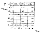
제6도는 맵테이블의 구체적인 일실시예를 나타낸 설명도.6 is an explanatory diagram showing a specific embodiment of a map table.
제7도, 제8도 및 제9도는 각각 종래예의 문제점을 나타낸 설명도.7, 8 and 9 are explanatory diagrams showing problems of the conventional example, respectively.
제10도는 본원 발명의 다른 실시예의 플로도.10 is a flow diagram of another embodiment of the present invention.
본원 발명은 연료분사방식의 내연기관에 관한 것이며. 특히 저회전시에서의 엔진의 안정성이 문제로 되는 자동차용 엔진에 적합한 연료분사장치에 관한 것이다.The present invention relates to an internal combustion engine of a fuel injection method. In particular, the present invention relates to a fuel injection device suitable for an engine for automobiles in which engine stability is a problem at low revolutions.
자동차용 엔진등에서는 액셀러레이터페달(accelerator pedal)을 되돌려서 저속상태로 했을 때, 또는 아이들상태로 했을 때에 회전이 불안정하게 되는 현상이 생길 때가 있다.In automobile engines or the like, rotation may become unstable when the accelerator pedal is turned to low speed or idle.
종래, 이와 같은 현상에 대처하기 위해 예를들면 일본국 특개소 59-231144호 공보, 특개소 60-30446호 공보에 기재된 바와 같이, 감속시에 아이들스위치의 신호에 의해 리치(rich)보정을 하는 것으로 개선하는 방법이 알려져 있었다. 그러나, 이 방법으로는 엔진이 정상상태로 도달한 다음에서의 운전특성을 개선할 수는 없었다.Conventionally, in order to cope with such a phenomenon, as described in Japanese Patent Laid-Open Nos. 59-231144 and 60-30446, for example, rich correction is performed by signals of an idle switch during deceleration. It was known how to improve. However, this method could not improve the operating characteristics after the engine reached steady state.
본원 발명은 전술한 배경하에 이루어진 것으로서, 그 목적으로 하는 바는 저속회전시에서의 엔진회전변동 및 서징(surging)의 억제의 충분하고, 안정된 운전상태가 얻어지도록 한 연료분사장치를 제공하는데 있다.SUMMARY OF THE INVENTION The present invention has been made under the above-described background, and an object thereof is to provide a fuel injection value which allows a sufficient and stable operating state of engine rotational fluctuations and surging to be suppressed at low speeds.
본원 발명의 특징은 내연기관의 흡입공기량, 회전수 및 온도를 포함하는 각종 작동파라미터에 따라 미리 프로그램된 제어내용에 따라서 연료분사밸브의 밸브개방시간을 제어하는 방식의 연료분사장치에 있어서, 엔진의 제어목표회전수와 실회전수와의 차이 및 단위시간당 회전수의 변화량의 최소한 한쪽의 데이터를 검출하는 수단을 설치하고, 이 데이터를 상기 작동파라미터에 포함하여 상기 연료분사밸브의 밸브개방시간을 제어하도록 구성한 것을 특징으로 하는 연료분사장치에 있다.A feature of the present invention is a fuel injection device of a method of controlling a valve opening time of a fuel injection valve in accordance with a control content programmed in advance according to various operating parameters including an intake air amount, a rotation speed, and a temperature of an internal combustion engine. Means for detecting at least one data of the difference between the control target rotational speed and the actual rotational speed and the change amount of the rotational speed per unit time are provided, and this data is included in the operating parameter to control the valve opening time of the fuel injection valve. A fuel injection device, characterized in that configured to.
다음에, 도면에 따라서 본원 발명의 실시예에 대하여 설명한다.Next, the Example of this invention is described according to drawing.
통상의 엔진의 공연비(空燃比)(A/F)에 대한 토크특성은 제7도에 나타낸 바와 같이 되어 있으며, 공연비가 13부근에서 토크의 변화가 가장 작아진다. 그러나, 연료소비량, 배기가스 등에 대한 요구로부터 실제로는 공연비는 13보다도 린(lean)인 14.7 또는 더욱 린쪽으로 제어되어 있는 것이 일반적이므로, 약간의 공연 비변동에 의해서도 커다란 토크변화에 이어져서, 엔진회전의 불안전상태를 초래하는 원인으로 된다.The torque characteristic with respect to the air-fuel ratio (A / F) of a normal engine is as shown in FIG. 7, and the change of torque is smallest in the air fuel ratio around 13. However, since the air-fuel ratio is generally controlled to 14.7, which is lean than 13, or even lean from the demand for fuel consumption, exhaust gas, and the like, engine torque is increased even by slight fluctuations in air performance. This may cause an unsafe condition.
제8도는 이와 같은 엔진의 회전수변동의 일예이며, 엔진회전수를 목표치 Nset로 되도록 제어했음에도 불구하고, 실제로는 △N의 회전편차와 dN/dt의 회전변동이 생겨 버리는 것을 나타내고 있다. 따라서, 안정되어 있는 것일수록 이들 △N,dN/dt가 작게 되어 있다고 할 수 있다.FIG. 8 is an example of such a rotational speed change of the engine, and shows that in spite of controlling the engine speed to be the target value N set , the rotational deviation of? N and the rotational change of dN / dt actually occur. Therefore, it can be said that these ΔN, dN / dt are smaller as they are more stable.
이것을 제9도에 의해 더욱 상세하게 설명하면, 본원 발명이 적용되는 저속도 조건에서는 스로틀밸브는 전폐(全閉)상태이므로, 스로틀밸브를 우회하는 아이들회전제어용 ISC(idle speed control)밸브로부터의 공기량은 변화하고 있기는 하지만, 공기량은 대략 일정하다고 생각해도 된다. 따라서, 연료분사밸브의 밸브개방시간 TP=Qa/N은 Qa가 대략 일정한 것으로부터 N에 비례하여 결정된다. 그런데, 엔진에서의 연소를 생각해보면 흡기행정에서 분사된 연료는 그로부터 2행정 후의 폭발행정에서 토크를 발생하므로, 엔진의 신호의 정보도 2행정 지연되게 되어서, 현실적으로 필요한 분사정보 TP에 대해 엔진에는 (TP)c가 분사되고 있는 것으로 되기 때문에, 연료공급량에 △TP의 밸브개방시간에 상당하는 오차가 생겨서, 그 만큼 A/F가 어긋나므로, 제7도에서 설명한 토크의 변동이 나타나 버리는 것이다.9, the amount of air from the idle speed control (ISC) valve for idle rotation control bypassing the throttle valve is reduced because the throttle valve is fully closed under the low speed condition to which the present invention is applied. Although it is changing, you may think that the amount of air is substantially constant. Therefore, the valve opening time T P = Qa / N of the fuel injection valve is determined in proportion to N since Qa is approximately constant. However, consider a combustion in the engine, the injection in the intake stroke fuel therefrom 2 it generates a torque in the power stroke after stroke, be presented information in the signal of the
그래서, 본원 발명에서는 이 밸브개방시간에 나타나는 오차 △TP를 억제하기 위해, 공연비 A/F를 변화시키도록 한 점을 특징으로 한다.Therefore, the present invention is characterized in that the air-fuel ratio A / F is changed to suppress the error ΔT P appearing in the valve opening time.
다음에, 본원 발명에 의한 연료분사장치에 대하여 도시한 실시예에 의해 상세히 설명한다.Next, the fuel injection device according to the present invention will be described in detail with reference to the illustrated embodiment.
제2도는 본원 발명의 일실시예가 적용된 엔진시스템의 일예이며, 도면에 있어서, 엔진(1)은 기통수에 대응한 수의 인젝터(3)를 흡기관(2)에 구비하고 있다. 이 흡기관(2)은 상류의 콜렉터(4)에서 하나로 합치고, 다시 상류에 엔진(1)의 흡입공기량을 조정하는 스로틀밸브(5)를 구비하고 있다.2 is an example of an engine system to which an embodiment of the present invention is applied, and in the drawing, the
또, 이 스로틀밸브(5)를 바이패스하여 엔진(1)의 회전수를 제어하기 위한 ISC밸브(6)가 설치되어 있으며, 스로틀밸브(5)가 전폐위치에 있을때, 이 ISC밸브(6)의 제어에 의해 엔진(1)의 회전수를 제어할 수 있다.Moreover, the
한편, 엔진(1)의 흡기량은 더욱 상류에 설치되어 있는 공기유량센서(7)에 의해 검출되며, 또 엔진(1)의 회전수는 회전센서(8)에 의해 검출된다.On the other hand, the intake air amount of the
그 밖에, 콘트롤유니트(9)에는 엔진온도센서(10), 배기가스센서(11)로부터의 신호도 입력되어 있으며, 이것에 의해 필요한 제어가 수행되도록 되어 있다.In addition, signals from the
엔진(1)에 대한 연료의 공급은 인젝터(3)의 밸브개방에 의해 행해지며, 이때의 공급량의 계량은 밸브개방시간의 제어에 의해 행해진다.The supply of fuel to the
또, 연료는 연료펌프(12)와 연압레귤레이터(13)에 의해 가압조압(加壓調壓)되어 인젝터(3)에 공급되고 있다.The fuel is pressurized by the fuel pump 12 and the
제3도는 콘트롤유니트(9)의 연료분사밸브(3)를 제어하는 부분의 블록도이며, 공기유량센서(7), 회전센서(8), 엔진온도센서(10), 배기가스센서(11) 등의 작동파라미터가 밸브개방시간결정수단(14)에 입력되어 있다.FIG. 3 is a block diagram of a part of controlling the
또한, 회전센서(8)로부터의 실제의 회전수는 목표회전수설정수단(5)으로 설정되는 목표회전수와의 편차 및 단위시간당 회전수의 변화량의 최소한 한쪽의 데이터를 검출하는 회전수변동검출수단(16)으로 보내진다. 이 회전수변동검출수단(17)의 데이터는 보정성분발생수단(17)으로 보내져서 연료분사밸브(3)의 밸브개방시간을 보정하는 보정성분으로 변환되어 밸브개방시간결정수단(14)의 작동파라미터의 하나로서 입력된다.In addition, the actual rotation speed from the
다음에, 이 실시예의 동작에 대하여 설명한다.Next, the operation of this embodiment will be described.
본원 발명은 회전수 N의 변동과 A/F의 변동이 관련하는 것으로부터, △N,dN/dt의 크기에 의해 A/F를 변화시키는 것이다. 즉, 인젝터(3)의 최종적인 밸브개방시간 Ti을,In the present invention, since the variation in rotational speed N and the variation in A / F are related, A / F is changed by the magnitude of ΔN, dN / dt. That is, the final valve opening time T i of the
Ti=TP(1+K1+K2…+K3+KTR)+TS……………………………………… (1)T i = T P (1 + K 1 + K 2 … + K 3 + K TR ) + T S ... … … … … … … … … … … … … … … (One)
에 의해 계산하도록 한 것이다. 여기서, TP는 Qa/N에 의해 결정되는 기본밸브개방시간, K1,K2,K3등은 엔진의 온도 등에 의해 정해지는 보정계수이다. 그리고, TS는 인젝터(3)에 의한 밸브개방지연시간을 보상하기 위한 계수이다.To be calculated by. Here, T P is a basic valve opening time determined by Qa / N, and K 1 , K 2 , K 3 , and the like are correction factors determined by the engine temperature and the like. In addition, T S is a coefficient for compensating the valve opening prevention time by the
그리고, 제수 KTP가 본원 발명에 의해 부가된 것이다.And divisor K TP is added by this invention.
여기서, 목표로 하는 엔진회전수 Nset로부터의 오차 △N, 및 회전수의 변화량 dN/dt과 A/F와의 관계에 대해 설명한다. 아이들 및 저속주행시는 스로틀밸브(5)는 전폐에 가까운 상태에 있으며, 이 때에는 흡입공기량 Qa은 거의 일정하다. 따라서, 본래 이 상태에서의 회전변화는 발생할 수 없는 것이다.Here, the relationship between the error? N from the target engine speed N set and the change amount dN / dt of the rotation speed and A / F will be described. At idle and low speed driving, the
그러나, 예를들면 어떤 외란(外亂)(A/F라도 좋고, 또는 다른 외란이라도 좋음)이 작용한 경우, 회전수의 변동이 생긴다.However, for example, when any disturbance (A / F or other disturbance) is applied, the rotational speed changes.
그런데, 이 변동에는 정적인 것과 동적인 것으로 나눌 수 있다.However, this variation can be divided into static and dynamic.
먼저, 정적인 것으로서는 설정회전수 Nset에 대한 평균회전수의 오차 △N로서 나타나며, 이 오차 △N는 A/F에 비례하고, A/F가 리치로 될 수록 이 △N은 커진다. 이 관계를 제4도(a)에 나타낸다.First, a static set as the rotation speed will appear as an error △ N of the average number of rotation N of the set, the error △ N is proportional to A / F, and, A / F is lower the △ N is increased to be rich. This relationship is shown in FIG.
한편, 회전수의 변동 dN/dt은 동적인 변동이며, 이것이 커지면 운전자는 서징을 느끼게 된다. 여기서, 상기 △N,dN/dt는 회전수 변동검출수단(16)으로 검출된다.On the other hand, the variation dN / dt of the rotational speed is a dynamic variation, and when this becomes large, the driver feels surging. Here, DELTA N and dN / dt are detected by the rotation speed fluctuation detecting means 16.
따라서, 운전성을 좋게 하기 위해서는 이 dN/dt를 작게 할 필요가 있다. 이 dN/dt와 A/F와의 관계는 제9도에서도 설명한 바와 같이, 단순한 비례관계는 아니고 제4도(b)에 나타낸 바와 같이 A/F의 미소한 변화도 확대된 형태로 dN/dt에 반영된다.Therefore, in order to improve operability, it is necessary to make this dN / dt small. The relationship between dN / dt and A / F is not a simple proportional relationship as described in FIG. 9, but rather a slight change in A / F as shown in FIG. 4 (b). Is reflected.
그래서, 본원 발명의 실시예에서는 이 제4도에 따라서 이것을 소거하도록 해서 보정성분발생수단(17)에서 보정계수 KTP를 부여하도록 하고 있다. 구체적으로는 제5도에 나타낸 바와 같은 맵(map)형태의 테이블을 사용하여, 콘트롤유니트(9)의 CPU에 의해 제1도에 나타낸 바와 같이 처리하는 것으로 실시할 수 있다.Therefore, in the embodiment of the present invention, the correction component generating means 17 gives the correction coefficient K TP by eliminating this according to FIG. Specifically, it can be performed by processing the CPU as shown in FIG. 1 by the CPU of the control unit 9 using a table in the form of a map as shown in FIG.
이 제5도의 테이블은 △N와 dN/dt를 변수로 하여 계수 KTP를 부여하는 것으로서, 제1도에 있어서 먼저 S1에서 데이터 N,Qa를 수신하고, 이어서 S2에서 ISC(idle speed control)가 행해지고 있는지의 여부를 조사하고, 결과가 YES일때에는 S3의 처리로 데이터 △N,dN/dt를 구하고, 계속되는 S4에서 맵테이블을 검색하여 데이터 KTP를 구한다. 그후, S5의 처리에서 밸브개방시간 Ti을 계산하고, S6에서 이 밸브개방시간 Ti을 인젝터(3)에 출력하여 처리를 끝낸다. 한편, S2에서의 결과가 NO로 되어 있을 때, 즉 ISC가 행해지고 있지 않았을 때에는 이 처리후 즉시 S6의 처리로 향하여, 전회와 같은 데이터 Ti를 출력한다.The table of FIG. 5 assigns the coefficient K TP by using? N and dN / dt as variables, and in FIG. 1 first receives data N, Qa at S1, and then at I2 (idle speed control) at S2. If the result is YES, the data? N, dN / dt is obtained by the process of S3, and the data K TP is obtained by searching the map table at the subsequent S4. Then, valve opening time Ti is calculated by the process of S5, and this valve opening time Ti is output to the
제6도는 예를들면 2000cc급의 엔진을 탑재한 자동차의 테스트 결과에 의한 테이블의 테이터내용의 일예를 나타낸 것으로, △N이 +84rpm에서 2%, dN/dt가 +84rpm/40ms에서 -0.07%의 값으로 되어 있다. 그리고, 이 테이블을 채용한 것에 의해 서징, 즉 dN/dt가 발생한 경우에도 그것에 대응한 KTP에 의한 보정이 행해지며, dN/dtk=0,△N=0의 상태로 수속(收束)되어, 서징을 충분히 억제할 수 있다.FIG. 6 shows an example of data contents of a table based on a test result of a vehicle equipped with a 2000cc engine, for example, ΔN is 2% at +84 rpm and dN / dt is -0.07% at +84 rpm / 40 ms. Is the value of. Then, the surging, i.e., dN / dt is a correction, even by a K TP corresponding thereto when said generated performed, dN / dtk = 0, △ N = procedures (收束) 0 status by employing this table Surging can be fully suppressed.
그리고, 이상의 실시예에서는 ISC가 행해지고 있는 시스템의 경우, 즉 목표회전수 Nset가 존재하고 있는 시스템의 경우에 대해 설명했지만, 데이터 △N가 존재하지 않는 시스템일 때에는 데이터 dN/dt만에 의해 테이블검색을 하도록 해도 좋은 것은 물론이다.Incidentally, in the above embodiment, the system in which the ISC is performed, that is, the system in which the target rotational speed N set is present, has been described. However, in the case of the system in which no data? Of course, you can do a search.
예를들면 제10도에 나타낸 플로도에서 설명하면, S1에서 데이터 N,Qa를 수신하고, 이어서 S3에서 회전변동 dN/dt을 구하며, 계속되며 S4에서 맵검색을 하여 데이터 KTP를 구한다. 이 데이터 KTP는 제5도에 나타낸 dN/dt와 △N을 변수로 하는 맵이 아니라, dN/dt를 변수로 하는 맵이다.For example, in the flowchart shown in FIG. 10, data N and Qa are received at S1, and then rotational variation dN / dt is obtained at S3, followed by map search at S4 to obtain data K TP . This data K TP is not a map using dN / dt and ΔN shown in FIG. 5 as variables, but a map using dN / dt as a variable.
그후, S5의 처리에서 밸브개방시간 Ti을 계산하고, S6에서 이 밸브개방시간 Ti을 인젝터(3)에 출력하여 처리를 끝낸다.Then, valve opening time Ti is calculated by the process of S5, and this valve opening time Ti is output to the
이상 설명한 바와 같이, 본원 발명에 의하면 회전수편차나 회전수변동에 따라서 공연비가 제어되며, 이것에 의해 회전수가 목표회전수로 수속되어 감으로써, 서징등이 충분히 억제되어 우수한 운전성을 부여할 수 있다.As described above, according to the present invention, the air-fuel ratio is controlled in accordance with the rotational deviation and the rotational speed fluctuation, whereby the rotational speed is converged to the target rotational speed, so that surging and the like are sufficiently suppressed, thereby providing excellent operability. have.
Claims (2)
Applications Claiming Priority (3)
| Application Number | Priority Date | Filing Date | Title |
|---|---|---|---|
| JP??60-186639 | 1985-08-27 | ||
| JP85-186639 | 1985-08-27 | ||
| JP60186639A JPS6248940A (en) | 1985-08-27 | 1985-08-27 | Engine controller |
Publications (2)
| Publication Number | Publication Date |
|---|---|
| KR870002361A KR870002361A (en) | 1987-03-31 |
| KR930000006B1 true KR930000006B1 (en) | 1993-01-06 |
Family
ID=16192104
Family Applications (1)
| Application Number | Title | Priority Date | Filing Date |
|---|---|---|---|
| KR1019860005851A KR930000006B1 (en) | 1985-08-27 | 1986-07-19 | Fuel injection system |
Country Status (5)
| Country | Link |
|---|---|
| US (1) | US4821698A (en) |
| EP (1) | EP0216111B1 (en) |
| JP (1) | JPS6248940A (en) |
| KR (1) | KR930000006B1 (en) |
| DE (1) | DE3675308D1 (en) |
Families Citing this family (11)
| Publication number | Priority date | Publication date | Assignee | Title |
|---|---|---|---|---|
| DE3867149D1 (en) * | 1987-06-27 | 1992-02-06 | Bosch Gmbh Robert | FUEL INJECTION PUMP FOR SUPPLYING THE COMBUSTION SPACE OF VEHICLE ENGINES PROVIDED FOR VEHICLE DRIVES. |
| US4903660A (en) * | 1987-11-19 | 1990-02-27 | Fuji Jukogyo Kabushiki Kaisha | Fuel injection control system for an automotive engine |
| US4930479A (en) * | 1988-05-24 | 1990-06-05 | Toyota Jidosha Kabushiki Kaisha | Irregular combustion determining device for an internal combustion engine |
| US4922877A (en) * | 1988-06-03 | 1990-05-08 | Nissan Motor Company, Limited | System and method for controlling fuel injection quantity for internal combustion engine |
| JP2794715B2 (en) * | 1988-07-19 | 1998-09-10 | スズキ株式会社 | Fuel injection device for multi-cylinder two-cycle engine |
| JP2502385B2 (en) * | 1989-09-06 | 1996-05-29 | 株式会社日立製作所 | Method and apparatus for controlling fuel amount and ignition timing of internal combustion engine |
| EP0486003B1 (en) * | 1990-11-13 | 1999-08-25 | Yamaha Hatsudoki Kabushiki Kaisha | Apparatus and method for controlling an internal combustion engine |
| US5371545A (en) * | 1992-03-11 | 1994-12-06 | Thomson Consumer Electronics, Inc. | Auxiliary video data slicer with adjustable window for detecting the run in clock |
| US5494018A (en) * | 1994-10-28 | 1996-02-27 | General Motors Corporation | Altitude dependent fuel injection timing |
| US5730105A (en) * | 1996-10-17 | 1998-03-24 | Outboard Marine Corporation | Idle control for internal combustion engine |
| DE10252399B4 (en) * | 2002-11-12 | 2006-04-27 | Mtu Friedrichshafen Gmbh | Method for controlling an internal combustion engine-generator unit |
Family Cites Families (17)
| Publication number | Priority date | Publication date | Assignee | Title |
|---|---|---|---|---|
| US3786789A (en) * | 1971-11-15 | 1974-01-22 | Gen Motors Corp | Electronic fuel injection system having coarse and fine speed compensation |
| GB2024462B (en) * | 1978-05-08 | 1983-03-30 | Bendix Corp | Integrated closed loop engine control system |
| JPS5862335A (en) * | 1981-10-09 | 1983-04-13 | Mazda Motor Corp | Control device of idling revolution in engine |
| JPS5862334A (en) * | 1981-10-09 | 1983-04-13 | Mazda Motor Corp | Control device of idling revolution in engine |
| JPS58195043A (en) * | 1982-05-11 | 1983-11-14 | Nissan Motor Co Ltd | Speed controller for internal-combustion engine |
| JPS5934440A (en) * | 1982-08-19 | 1984-02-24 | Honda Motor Co Ltd | Control method of air-fuel ratio of mixture for internal conbustion engine for vehicle |
| DE3238189A1 (en) * | 1982-10-15 | 1984-04-19 | Robert Bosch Gmbh, 7000 Stuttgart | IDLE CONTROL SYSTEM FOR AN INTERNAL COMBUSTION ENGINE |
| JPS59185833A (en) * | 1983-04-06 | 1984-10-22 | Honda Motor Co Ltd | Fuel feed control method of internal-combustion engine |
| FR2544798B1 (en) * | 1983-04-22 | 1987-12-11 | Renault | DEVICE FOR CONTROLLING THE RPM OF A DIESEL ENGINE BY ELECTRONIC REGULATION OF THE FUEL FLOW INJECTED BY THE INJECTION PUMP |
| DE3323723C3 (en) * | 1983-07-01 | 1999-02-11 | Bosch Gmbh Robert | Method and device for controlling the overrun operation of an internal combustion engine |
| DE3346436A1 (en) * | 1983-12-22 | 1985-09-05 | Robert Bosch Gmbh, 7000 Stuttgart | IDLE SPEED CONTROL DEVICE FOR INTERNAL COMBUSTION ENGINES |
| JPS60138245A (en) * | 1983-12-26 | 1985-07-22 | Toyota Motor Corp | Fuel injection control device of engine |
| US4580535A (en) * | 1985-06-03 | 1986-04-08 | Mitsubishi Jidosha Kogyo Kabushiki Kaisha | Engine idling speed controlling system |
| JPS6138139A (en) * | 1984-07-30 | 1986-02-24 | Nippon Denso Co Ltd | Fuel injection control device in internal-combustion engine |
| JPS6181546A (en) * | 1984-09-28 | 1986-04-25 | Honda Motor Co Ltd | Feedback control method for number of idle revolutions of internal-combustion engine |
| JPS61207848A (en) * | 1985-03-13 | 1986-09-16 | Honda Motor Co Ltd | Suction air amount control in idling for internal-combustion engine |
| JPH0612088B2 (en) * | 1985-05-31 | 1994-02-16 | 本田技研工業株式会社 | Fuel supply control method during idling of internal combustion engine |
-
1985
- 1985-08-27 JP JP60186639A patent/JPS6248940A/en active Pending
-
1986
- 1986-07-19 KR KR1019860005851A patent/KR930000006B1/en not_active IP Right Cessation
- 1986-08-11 US US06/895,217 patent/US4821698A/en not_active Expired - Fee Related
- 1986-08-13 EP EP86111211A patent/EP0216111B1/en not_active Expired - Lifetime
- 1986-08-13 DE DE8686111211T patent/DE3675308D1/en not_active Expired - Lifetime
Also Published As
| Publication number | Publication date |
|---|---|
| EP0216111A2 (en) | 1987-04-01 |
| US4821698A (en) | 1989-04-18 |
| DE3675308D1 (en) | 1990-12-06 |
| KR870002361A (en) | 1987-03-31 |
| EP0216111B1 (en) | 1990-10-31 |
| JPS6248940A (en) | 1987-03-03 |
| EP0216111A3 (en) | 1988-02-03 |
Similar Documents
| Publication | Publication Date | Title |
|---|---|---|
| US4391253A (en) | Electronically controlling, fuel injection method | |
| US5660157A (en) | Output torque control apparatus and method for an internal combustion engine | |
| US4771752A (en) | Control system for internal combustion engines | |
| US4244023A (en) | Microprocessor-based engine control system with acceleration enrichment control | |
| US4789939A (en) | Adaptive air fuel control using hydrocarbon variability feedback | |
| KR930005180B1 (en) | Air fuel ratio adaptive control apparatus | |
| KR890000500B1 (en) | Air-fuel ratio control apparatus for internal combustion engines | |
| KR930000006B1 (en) | Fuel injection system | |
| US4440119A (en) | Electronic fuel injecting method and device for internal combustion engine | |
| US5058550A (en) | Method for determining the control values of a multicylinder internal combustion engine and apparatus therefor | |
| US4487190A (en) | Electronic fuel injecting method and device for internal combustion engine | |
| US4463732A (en) | Electronic controlled non-synchronous fuel injecting method and device for internal combustion engines | |
| US4697563A (en) | Method of controlling the operation of an automotive internal combustion engine | |
| JPH01237333A (en) | Control device for internal combustion engine | |
| JP2510991B2 (en) | Engine controller | |
| US4357922A (en) | Method and apparatus for operating a fuel-supply system with lambda control | |
| US5003955A (en) | Method of controlling air-fuel ratio | |
| US4741312A (en) | Air-fuel ration control system for an automotive engine | |
| US4469073A (en) | Electronic fuel injecting method and device for internal combustion engine | |
| KR900001300B1 (en) | Fuel-injection control system for gasoline engine | |
| US5341786A (en) | Fuel injection control device for internal combustion engine | |
| US4662339A (en) | Air-fuel ratio control for internal combustion engine | |
| US5775295A (en) | Process for controlling a direct-injection internal combustion engine | |
| JPH04166637A (en) | Air-fuel ratio controller of engine | |
| JPH06173739A (en) | Control system for measuring fuel of internal combustion engine |
Legal Events
| Date | Code | Title | Description |
|---|---|---|---|
| A201 | Request for examination | ||
| E902 | Notification of reason for refusal | ||
| G160 | Decision to publish patent application | ||
| E701 | Decision to grant or registration of patent right | ||
| GRNT | Written decision to grant | ||
| FPAY | Annual fee payment |
Payment date: 19991230 Year of fee payment: 8 |
|
| LAPS | Lapse due to unpaid annual fee |