KR920008809B1 - Cylinder actuator - Google Patents
Cylinder actuator Download PDFInfo
- Publication number
- KR920008809B1 KR920008809B1 KR1019860008753A KR860008753A KR920008809B1 KR 920008809 B1 KR920008809 B1 KR 920008809B1 KR 1019860008753 A KR1019860008753 A KR 1019860008753A KR 860008753 A KR860008753 A KR 860008753A KR 920008809 B1 KR920008809 B1 KR 920008809B1
- Authority
- KR
- South Korea
- Prior art keywords
- piston
- cylinder
- cylinder tube
- connecting member
- drive
- Prior art date
Links
Images


Classifications
-
- F—MECHANICAL ENGINEERING; LIGHTING; HEATING; WEAPONS; BLASTING
- F15—FLUID-PRESSURE ACTUATORS; HYDRAULICS OR PNEUMATICS IN GENERAL
- F15B—SYSTEMS ACTING BY MEANS OF FLUIDS IN GENERAL; FLUID-PRESSURE ACTUATORS, e.g. SERVOMOTORS; DETAILS OF FLUID-PRESSURE SYSTEMS, NOT OTHERWISE PROVIDED FOR
- F15B15/00—Fluid-actuated devices for displacing a member from one position to another; Gearing associated therewith
- F15B15/08—Characterised by the construction of the motor unit
- F15B15/14—Characterised by the construction of the motor unit of the straight-cylinder type
-
- F—MECHANICAL ENGINEERING; LIGHTING; HEATING; WEAPONS; BLASTING
- F15—FLUID-PRESSURE ACTUATORS; HYDRAULICS OR PNEUMATICS IN GENERAL
- F15B—SYSTEMS ACTING BY MEANS OF FLUIDS IN GENERAL; FLUID-PRESSURE ACTUATORS, e.g. SERVOMOTORS; DETAILS OF FLUID-PRESSURE SYSTEMS, NOT OTHERWISE PROVIDED FOR
- F15B11/00—Servomotor systems without provision for follow-up action; Circuits therefor
- F15B11/02—Systems essentially incorporating special features for controlling the speed or actuating force of an output member
- F15B11/028—Systems essentially incorporating special features for controlling the speed or actuating force of an output member for controlling the actuating force
- F15B11/036—Systems essentially incorporating special features for controlling the speed or actuating force of an output member for controlling the actuating force by means of servomotors having a plurality of working chambers
-
- F—MECHANICAL ENGINEERING; LIGHTING; HEATING; WEAPONS; BLASTING
- F15—FLUID-PRESSURE ACTUATORS; HYDRAULICS OR PNEUMATICS IN GENERAL
- F15B—SYSTEMS ACTING BY MEANS OF FLUIDS IN GENERAL; FLUID-PRESSURE ACTUATORS, e.g. SERVOMOTORS; DETAILS OF FLUID-PRESSURE SYSTEMS, NOT OTHERWISE PROVIDED FOR
- F15B2211/00—Circuits for servomotor systems
- F15B2211/30—Directional control
- F15B2211/305—Directional control characterised by the type of valves
- F15B2211/30525—Directional control valves, e.g. 4/3-directional control valve
-
- F—MECHANICAL ENGINEERING; LIGHTING; HEATING; WEAPONS; BLASTING
- F15—FLUID-PRESSURE ACTUATORS; HYDRAULICS OR PNEUMATICS IN GENERAL
- F15B—SYSTEMS ACTING BY MEANS OF FLUIDS IN GENERAL; FLUID-PRESSURE ACTUATORS, e.g. SERVOMOTORS; DETAILS OF FLUID-PRESSURE SYSTEMS, NOT OTHERWISE PROVIDED FOR
- F15B2211/00—Circuits for servomotor systems
- F15B2211/70—Output members, e.g. hydraulic motors or cylinders or control therefor
- F15B2211/71—Multiple output members, e.g. multiple hydraulic motors or cylinders
- F15B2211/7107—Multiple output members, e.g. multiple hydraulic motors or cylinders the output members being mechanically linked
Abstract
내용 없음.No content.
Description
제1도는 본 발명의 제1실시예에 따른 실린더 작동기 및 제어회로를 나타내는 사시도.1 is a perspective view showing a cylinder actuator and a control circuit according to a first embodiment of the present invention.
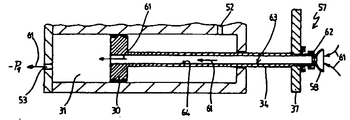
제2도는 제1도의 실린더 작동기의 종단면도.2 is a longitudinal sectional view of the cylinder actuator of FIG.
제3도 및 제4도는 작업 조정장치의 형태를 취하는 본 발명의 두개의 다른 실시예들 및 복귀 피스톤 및 그 피스톤 로드의 다른 형태들을 나타내는 도면.3 and 4 show two different embodiments of the present invention taking the form of a work adjustment device and other forms of return piston and its piston rod.
* 도면의 주요부분에 대한 부호의 설명* Explanation of symbols for the main parts of the drawings
5 : 실린더 블록 6, 7 : 실린더 구멍5: cylinder block 6, 7: cylinder hole
14, 15 : 실린더 튜브 17 : 동력 플런저14, 15: cylinder tube 17: power plunger
30 : 복귀 피스톤 34 : 피스톤 로드30: return piston 34: piston rod
37 : 연결부재 44 : 조종장치37: connecting member 44: control device
45 : 제어장치 54, 55 : 센서45: control device 54, 55: sensor
58 : 흡인기 65 : 전자기 장치58: aspirator 65: electromagnetic device
68 : 바아68: Bar
본 발명은 실린더 작동기에 관한 것이고, 특히 축향으로 활주되는 출력부재의 일부를 형성하거나 또는 동출력부재에 결합되게 되는 축향으로 활주되는 피스톤을 갖는, 조종기능을 보유하는, 실린더 작동기에 관한 것이다. 상기 출력부재의 일단부는 하중물(load)와 근접되고 동시에 작업이 수행될 수 있는 특정물과의 연결을 위한 예컨대 파지수단과 같은 수단과 연결되게 되는 작동기의 일단부로부터 그 일단부가 돌출되게 되고, 상기 작동기의 다른 단부는 차폐되게 된다.The present invention relates to a cylinder actuator, and more particularly to a cylinder actuator having a steering function, which forms part of an axially slidable output member or has an axially slidable piston which is to be coupled to the same output member. One end of the output member protrudes from one end of the actuator which is in close proximity to the load and at the same time connected to a means such as a gripping means for connection with a particular object on which the work can be performed, The other end of the actuator is to be shielded.
상기와 같은 실린더 작동기들은 통상적으로 피스톤을 구비하며 동 피스톤의 피스톤 로드는 실린더 작동기의 양 측면으로부터 연장되어 실린더 튜브의 단부 캡들을 관통하여 유체 밀봉식으로 운전되게 된다. 이 경우 피스톤 로드의 한 부분은 출력 부재로서 작용하고 다른 한 부분은 단지 피스톤을 안내하고 안정시키는 기능만을 가져서 피스톤의 정확한 이동을 보장하고 출력 부재상에 작용하는 굽힘력(bending forces)들을 감소시키게 된다. 상기 출력부재는 가공물등을 조종하기 위해 예컨대 파지부재 또는 집게부재와 연결되어 상기 출력부재의 변위에 의해 가공물이 정위되도록 할 수 있다. 상기와 같이 통상적으로 설계되는 실린더 작동기의 단점은 정확한 변위를 보장하기 위해 요청되는 정교한 구조, 및 안내작용을 수행하기 위한 피스톤의 제2부분에 기인하여 늘어나게 되는 전체길이에 있다. 상기한 결점이 중요한 사항으로 간주되는 이유는 실린더 작동기의 전체길이가 상기한 바와 같은 제2피스톤 로드 부분을 갖지 않는 통상적인 실린더 작동기의 두배가 되기 때문이다.Such cylinder actuators typically have a piston and the piston rod of the piston extends from both sides of the cylinder actuator to be fluidically operated through the end caps of the cylinder tube. In this case one part of the piston rod acts as an output member and the other part only has the function of guiding and stabilizing the piston to ensure correct movement of the piston and to reduce bending forces acting on the output member. . The output member may be connected to, for example, a gripping member or a forceps member to manipulate the workpiece, such that the workpiece is positioned by the displacement of the output member. Disadvantages of such cylinder actuators, which are typically designed as such, are their overall length, which is due to the elaborate structure required to ensure accurate displacement, and the second part of the piston for performing the guide action. The above-mentioned drawback is considered important because the overall length of the cylinder actuator is twice that of a conventional cylinder actuator without the second piston rod portion as described above.
본 발명의 주된 목적은 간단한 구조를 갖는, 최초에 언급한 형태의 실린더 작동기를 제공함에 있다.The main object of the present invention is to provide a cylinder actuator of the type mentioned first, with a simple structure.
본 발명의 다른 목적은 생산비가 저렴한 상기 실린더 작동기를 제공함에 있다.Another object of the present invention is to provide the cylinder actuator having a low production cost.
본 발명의 또 다른 목적은 특히 길이방향에서 간결한 크기를 갖는 상기 실린더 작동기를 제공함에 있다.It is a further object of the present invention to provide such a cylinder actuator having a particularly compact size in the longitudinal direction.
본 발명의 또 다른 목적은 피스톤이 이동할 때 피스톤의 면밀한 안내를 동시에 보장하게 되는 상기 실린더 작동기를 제공함에 있다.It is a further object of the present invention to provide such a cylinder actuator which ensures a close guiding of the piston as it moves.
상기 목적들 및 명세서 및 청구범위를 통하여 부각되게 되는 다른 목적들을 달성하기 위해, 피스톤 및 출력부재는 플런저 형태의 공통 부품의 형태를 취하며 상기 플런저는 일단부에서 실린더 구멍과 밀봉 접촉하여 상기 실린더 튜브내에 구동 공간을 마련한다. 플런저는 외측의, 예컨대 원통면을 갖고 동 원통면은 상기 실린더 튜브내로 연장되는 플런저의 대부분에 걸쳐서 상기 구멍과 밀봉접촉 및 활주 접촉하게 된다. 제1실린더 튜브에 근접하여 제2실린더 튜브가 마련되며 동 제2실린더 튜브는 상기 제1실린더 튜브에 평행하게 고정된다. 상기 제2튜브는 그 양단부가 차폐되게 되고 동 제2튜브내에서 축방향으로 활주되는 복귀 피스톤을 가지며 상기 복귀 피스톤은 제2튜브내의 공간을 두개의 피스톤 공간들로 분할한다. 두개의 실린더 튜브들의 일단부에는 연결부재가 위치되고 동 연결부재는 제1실린더 튜브로부터 돌출되는 출력부재의 부분 및 복귀 피스톤과 연결되면서 제2실린더 튜브로부터 유체 밀봉식으로 돌출되는 피스톤로드를 서로 결합시킨다. 또한 밸브와 같은 제어장치가 제공되는데 상기 밸브는 압력유체가 제1실린더 튜브내의 플런저 단부에 있는 구동 공간으로 유입되도록 하거나, 또는 제2실린더 튜브내의 피스톤 로드 둘레의 제2피스톤 공간으로 유입되도록 하면서 동시에 제2실린더 튜브내의 제1피스톤 공간은 유체를 배출시키도록 하는 방식으로 세팅된다.In order to achieve the above objects and other objects highlighted by the specification and the claims, the piston and the output member take the form of a common part in the form of a plunger and the plunger is in sealing contact with the cylinder bore at one end of the cylinder tube. A drive space is provided in the inside. The plunger has an outer side, for example a cylindrical surface, which is in sealing and sliding contact with the hole over most of the plunger extending into the cylinder tube. A second cylinder tube is provided in proximity to the first cylinder tube, and the second cylinder tube is fixed in parallel to the first cylinder tube. The second tube has a return piston whose ends are shielded and axially slides within the second tube, and the return piston divides the space in the second tube into two piston spaces. A connecting member is positioned at one end of the two cylinder tubes and the connecting member engages a portion of the output member projecting from the first cylinder tube and a piston rod projecting fluidically from the second cylinder tube while being connected to the return piston. Let's do it. A control device such as a valve is also provided, which allows the pressure fluid to enter the drive space at the plunger end in the first cylinder tube or into the second piston space around the piston rod in the second cylinder tube. The first piston space in the second cylinder tube is set in such a way as to drain the fluid.
그러므로 본 발명은 통상적인 단일작동식 실린더 작동기의 길이보다 기껏해야 약간 큰 길이를 갖게 되는 간결한 디자인의 실린더 작동기를 제공한다. 동시에, 플런저 피스톤 또는 동력 피스톤에 횡방향 힘들이 작용하는 경우에 있어서 조차도 동 피스톤을 고정밀 안내하게 되는 시스팀이 마련된다. 이와같은 고정밀 안내는 제1실린더 튜브내에서 플런저 피스톤이 비-유극의 헐거운 끼워맞춤(play-free running fit)됨으로써 가능하게 되며 동력 피스톤 또는 플런저의 길이는 동 피스톤이 실린더 튜브내에서 수축되는 길이와 실제적으로 동일하게 된다. 제1실린더 튜브의 구동공간에 압력을 가함으로써 예컨대, 조종을 수행하기 위한 수단의 반송체의 형태를 취할 수 있는 연결부재는 외측으로 이동된다. 제2실린더 튜브내의 제2피스톤 공간내로 압력유체를 공급시키면 상기 연결부재는 복귀된다. 동시에, 본 발명에 따라, 플런저와 제2피스톤을 연결시킴으로써 플런저의 비틀림을 방지하기 위한 수단이 마련되고 이와같은 비틀림 방지수단은 물체들을 소정위치로 정확하게 이동시키기 위해 조종할 때 매우 효과적이다. 그러므로 복귀 피스톤과 연결된 피스톤 로드는 한편으로는 연결부재 및 동력 피스톤을 복귀시키는 역할을 하며 다른 한편으로는 전체 배열체의 비틀림을 방지하는 역할을 하고, 반면 동력 피스톤 또는 플런저는 연결 부재를 외측으로 이동시키며 안정기능 또는 안내기능을 수행한다. 이점과 관련하여 동력 플런저의 직경이 비교적 크게되어 커다란 지지표면을 제공하게 되기 때문에 최적의 안내효과가 얻어지게 된다. 동시에 플런저의 대직경은, 동 플런저가 강성을 갖게 되고 플런저가 제1실린더 튜브로부터 완전히 연장되었을 때에도 작동기의 잔존부분에서 연결부재를 충분히 지지하게 된다는 것을 의미한다.The present invention therefore provides a compact actuator cylinder design having a length at most slightly larger than that of a conventional single acting cylinder actuator. At the same time, there is provided a system for high precision guiding the piston even in the case of lateral forces acting on the plunger piston or power piston. Such high-precision guidance is made possible by the plunger piston's play-free running fit in the first cylinder tube, and the length of the power piston or plunger is equal to the length of the piston being retracted in the cylinder tube. Practically the same. By applying pressure to the drive space of the first cylinder tube, for example, the connecting member, which can take the form of a carrier of the means for performing the steering, is moved outward. When the pressure fluid is supplied into the second piston space in the second cylinder tube, the connecting member is returned. At the same time, according to the present invention, a means for preventing twisting of the plunger by connecting the plunger and the second piston is provided and such twisting prevention means is very effective when manipulating to move the objects to a predetermined position accurately. The piston rod connected with the return piston therefore serves to return the connecting member and the power piston on the one hand and to prevent twisting of the entire arrangement on the other hand, while the power piston or plunger moves the connecting member outward. It performs stability function or guidance function. In this regard, the optimum guiding effect is obtained because the diameter of the power plunger is relatively large to provide a large support surface. At the same time the large diameter of the plunger means that the plunger is rigid and fully supports the connecting member at the remaining portion of the actuator even when the plunger is fully extended from the first cylinder tube.
본 발명의 다른 유효한 특성들은 청구의 범위로부터 알수 있게 된다.Other valid features of the invention will be apparent from the claims.
본 발명의 상기와 같은 특성들중의 하나에 따라, 실린더 튜브들은 각각 장방형 횡간단면을 가지며 각주의 형태를 취하고 그 축들에 평행한 상호 근접측면들을 따라 서로 결합된다. 선택적으로, 두개의 실린더 튜브들은 동 실린더 튜브들의 축에 수직한 평면에서 관찰되어졌을 때 장방형 횡간단면을 갖는 단일 각주 구조를 갖는 일체부들로 될 수 있다. 또한 두개의 실린더 튜브들은 특히 그 길이에 관련하여 동일한 외부 크기를 갖는다. 피스톤들은 근본적으로 동일한 최대 행정길이들을 가지며 실린더 튜브들의 중심 종축들은 튜브들의 대칭평면인 공통 평면내에 위치된다.According to one of the above characteristics of the invention, the cylinder tubes each have a rectangular transverse cross section, which take the form of a circumference and are joined together along mutually proximal sides parallel to their axes. Optionally, the two cylinder tubes can be integral parts having a single foot structure with a rectangular transverse cross section when viewed in a plane perpendicular to the axis of the cylinder tubes. The two cylinder tubes also have the same outer size, in particular in terms of their length. The pistons have essentially the same maximum stroke lengths and the central longitudinal axes of the cylinder tubes are located in a common plane, the plane of symmetry of the tubes.
본 발명의 이러한 특성은 실린더 작동기의 간결한 디자인에 또한 기여하고 부가적으로 실린더 튜브 블록의 장방형 횡간단면은 수개의 실린더 작동기들이 최소의 공간내에 배열될 수 있도록 하며 동 실린더 작동기들상에 특정의 돌출부가 없기 때문에 상기 실린더 작동기들이 맞추어진 상태로 서로 접촉을 유지하는 것이 가능하게 되도록 한다.This feature of the present invention also contributes to the compact design of the cylinder actuator and additionally the rectangular cross section of the cylinder tube block allows several cylinder actuators to be arranged in a minimal space and a particular protrusion on the cylinder actuators This makes it possible to keep the cylinder actuators in contact with each other in a fitted state.
본 발명의 다른 특성에 따라, 제2실린더 튜브내의 제1피스톤 공간은 구동 공기의 배기를 위한 오리피스를 갖는다. 이것은 실린더 작동기가 공기 구동식일 경우에 복귀 피스톤에 의해 배기되는 공기가 제1피스톤 공간으로부터 자유롭게 배출되기 때문에 두개의 피스톤들이 수축될 수 있다는 것을 의미한다.According to another feature of the invention, the first piston space in the second cylinder tube has an orifice for exhausting drive air. This means that when the cylinder actuator is air driven, the two pistons can be retracted because the air exhausted by the return piston is freed from the first piston space.
두개의 실린더 튜브들은 종방향으로 상기 튜브들은 관통하여 연장되는 도관(duct)을 갖는 각주 유니트를 형성하고 상기 도관의 일단부는 상기 제어장치와의 연결을 위해 연결부재로부터 이격된 상기 유니트의 단부에 마련되며 다른 단부는 제2실린더 튜브내의 제2피스톤 공간내로 이어지는 포트를 형성한다. 실린더 작동기는, 동작동기내의 도관이 제어장치와의 연결을 위해 연결부재로부터 이격된 유니트의 단부에 있는 일단부로부터 제1실린더 튜브내의 구동공간내로 이어지는 포트를 형성하는 다른 단부로 연장되어 제어장치에 의한 플런저의 작동을 가능하게 하도록, 또한 설계된다. 제2실린더 튜브내의 제1피스톤 공간이 연결부재로부터 이격된 유니트의 단부에서 동 공간으로부터 외측으로 이어지는 포트를 갖는것도 가능하다.The two cylinder tubes form a footnote unit having a duct extending longitudinally through the tubes and one end of the conduit is provided at the end of the unit spaced from the connecting member for connection with the control device. And the other end forms a port leading into the second piston space in the second cylinder tube. The cylinder actuator extends from one end at the end of the unit spaced from the connecting member to the other end forming a port leading into the drive space in the first cylinder tube for connection with the control device for connection with the control device. It is also designed to enable the operation of the plunger by means of It is also possible for the first piston space in the second cylinder tube to have a port running outward from the same space at the end of the unit spaced from the connecting member.
본 발명의 이러한 다른 특성에 따라, 공기압을 사용하는 실린더 작동기의 작동을 위한 중앙연결이 가능하며, 만약 모든 공기압력 연결체들이 연결부재로부터 이격될 실린더 유니트의 단부상에 배열된 경우 상기 중심연결이 매우 편리하게 된다. 이와같이 됨으로써, 실린더 작동기가 그 디자인에 있어서 직선형으로 되고 수개의 상기 실린더들이 나란히 사용되는 경우에도 동 실린더들에 공급되는 라인들의 배열은 정상적으로 신속하게 검사될 수 있다는 유용한 효과가 도출된다.According to this other feature of the invention, a central connection for the operation of a cylinder actuator using pneumatic pressure is possible, in which case the central connection is provided if all air pressure connectors are arranged on the end of the cylinder unit to be spaced apart from the connecting member. It becomes very convenient. This results in a useful effect that the arrangement of lines supplied to the cylinders can be quickly and normally inspected even when the cylinder actuator is straight in its design and several of the cylinders are used side by side.
연결부재를 경유하여 플런저에 결합되는 제2실린더 튜브의 피스톤 로드는 제1피스톤이 그 축을 중심으로 비틀림이 없이 직선 이동(translatory motion)하도록 한다. 본 발명의 이러한 다른 태양에 따라, 다른 부가적인 부품을 필요로 하지 않으면서 동력 피스톤 또는 플런저의 비틀림을 방지하기 위해 제공되는 복귀 피스톤 및 동 복귀 피스톤에 부착된 피스톤 로드의 유리한 조합적 사용이 가능하게 된다.The piston rod of the second cylinder tube, which is coupled to the plunger via the connecting member, causes the first piston to be in translatory motion without distortion about its axis. According to this further aspect of the invention, it is possible to advantageously use a combination of a return piston and a piston rod attached to the return piston provided to prevent twisting of the power piston or plunger without requiring other additional parts. do.
두개의 피스톤들을 서로 결합시키는 연결부재는 실린더를 하중물(Load)와 연결시키면서, 그 상부에서 작업을 수행할 수 있게 되는 수단을 위한 반송체로서 설계될 수 있다. 상기 연결수단은 예컨대 흡인장치, 파지 장치 또는 자기장치의 형태를 취할 수 있다. 연결부재가 자체적으로 작동기에 의해 작업이 수행되게 되는 하중물과의 직접적인 연결체를 형성하는 것도 가능하다.The connecting member which couples the two pistons together can be designed as a carrier for the means by which the cylinder is able to carry out work on its top while connecting the load. The connecting means can take the form of, for example, a suction device, a gripping device or a magnetic device. It is also possible that the connecting member itself forms a direct connection with the load on which the work is to be carried out by the actuator.
하중물(load)와의 연결을 제공하는 수단은 하나이상의 흡인기를 갖는 흡인 수단으로 구성될 수 있으며, 상기 흡인기는 흡인 연결도관을 경유하여 진공원과 연결된다. 복귀 피스톤 및 그에 결합된 피스톤 로드는 동 피스톤 및 피스톤 로드를 관통하여 연장되는 종방향 도관을 가질 수 있고, 상기 종방향 도관은 상기 흡인도관의 일부분을 형성하며 상기 흡인도관의 복귀 피스톤으로부터 이격된 일단부는 흡인수단과 연통되고 상기 흡인도관의 대향단부는 제2실린더 튜브내의 제1피스톤 공간내로 개방된다.The means for providing a connection with a load may consist of suction means having one or more aspirators, said aspirators being connected to a vacuum source via a suction connection conduit. The return piston and the piston rod coupled thereto may have a longitudinal conduit extending through the piston and the piston rod, the longitudinal conduit forming a portion of the suction conduit and spaced once from the return piston of the suction conduit The part communicates with the suction means and the opposite end of the suction conduit is opened into the first piston space in the second cylinder tube.
본 발명의 이와 같은 또다른 특성은 흡인 수단으로 이어지는 바람직하지 않은 외부 파이프들을 필요로 하지 않으면서 흡인기 형태의 조종장치의 간단한 작동을 가능하게 한다. 이 경우, 흡인도관은 특정의 다른 기능을 하지 않는 제1피스톤 공간에 의해 형성된다.This further feature of the present invention enables simple operation of the aspirator-type control without the need for undesirable external pipes leading to the suction means. In this case, the suction conduit is formed by the first piston space that does not perform any other function.
본 발명에 따른 실린더 작동기는 또한 하중물과의 직접적인 연결부를 형성하는 수단이 전기적으로 작동되는 장치로 구성되도록 설계될 수 있으며, 전기적으로 전도성을 띠면서 연결부재로부터 이격된 단부로부터 연장되는 축향구멍을 갖는 피스톤 로드에 의해 구성되는 전기적인 제어라인이 마련되게 된다. 전도성 바아는 연결부재로부터 이격된 제2실린더 튜브의 단부에 기계적으로 고정되면서 동 단부로부터 절연되고 피스톤 로드의 축향구멍 내부를 따라 종방향으로 연장되어 복구 피스톤의 축향위치에 무관하게 특정길이 이상의 상기 바아가 상기 축향 구멍내에 위치될 수 있도록 한다. 상기 바아상의 와이퍼 접점에 의해 피스톤 로드 및 바와 사이의 전기적인 접속부가 형성된다. 바아의 외측단부는 전기적인 단자를 가지며 동 전기단자에 의해 상기 외측단부는 외부의 전기 공급원과 접속되어 실린더 작동기에 의해 작동되는 하중물과의 직접적인 연결을 위한 연결 부재상의 수단에 전기 신호들을 공급하게 된다.The cylinder actuator according to the invention can also be designed such that the means for forming a direct connection with the load consists of an electrically operated device, the axial hole extending from an end which is electrically conductive and spaced apart from the connecting member. An electrical control line constituted by the piston rod having is provided. The conductive bar is mechanically fixed to the end of the second cylinder tube spaced from the connecting member and is insulated from the end and extends longitudinally along the inside of the axial bore of the piston rod to extend the bar beyond a specified length, regardless of the axial position of the recovery piston. To be located in the axial hole. The wiper contacts on the bar form an electrical connection between the piston rod and the bar. The outer end of the bar has an electrical terminal and by means of the electrical terminal the outer end is connected to an external electrical source to supply electrical signals to the means on the connecting member for direct connection with the load actuated by the cylinder actuator. do.
본 발명의 이러한 또다른 특성은 연결부재에의 전기적인 신호경로를 부여하기 위해 실린더 작동기의 부분들을 사용하는 것을 가능하게 한다. 그러므로 상기 신호경로의 대부분이 작동기내에 마련되며 따라서 외부배선이 감소되게 된다. 예컨대 연결부재상의 수단이 전자기적인 수단일 경우에, 신호 또는 작동 전류의 하나의 상(phase)가 바아 및 피스톤 로드를 경유하여 각각의 전가기적 장치에 공급되도록 하고 접지부는 실린더 튜브 블록을 단순히 접지시킴으로써 얻어질 수 있도록 하는 것이 가능하게 된다. 접지신호는 그리고 나서 동력 플런저 및 연결부재를 경유하여 전자기적 장치로 이어지게 된다.This further feature of the invention makes it possible to use parts of the cylinder actuator to impart an electrical signal path to the connecting member. Therefore, most of the signal paths are provided in the actuator, so that external wiring is reduced. For example, in the case where the means on the connecting member are electromagnetic means, one phase of the signal or operating current is supplied to each electric device via the bars and the piston rod and the grounding part is simply grounded by It becomes possible to obtain it. The ground signal then leads to the electromagnetic device via the power plunger and connecting member.
본 발명의 또다른 특성으로서 피스톤 로드 및 복귀 피스톤은 그 상부의 공통의 축향구멍을 갖는다. 실린더 작동기는 또한, 피스톤 로드 및 복귀 피스톤내의 상기 구멍 내부에서 연장되는 파이프로 구성되어 동 파이프가 동 파이프와 피스톤 로드 사이의 유체밀봉식 미끄럼 끼워맞춤을 유지하면서 상대 이동하는 것을 가능하게 한다. 파이프는 연결부재로부터 이격된 제2실린더 튜브의 단부에 고정되는 일단부를 가지며 다른 제2단부는 로드내의 축향구멍내에 위치된다. 파이프의 제1단부는 구동유체 공급원과 연결되어 연결부재상에 있는 산업용 로봇의 일부분과 같은 조종용 수단을 작동시키게 된다.As a further feature of the invention the piston rod and the return piston have a common axial bore at the top thereof. The cylinder actuator also consists of a pipe extending inside the hole in the piston rod and the return piston to allow the pipe to move relatively while maintaining a fluid tight sliding fit between the pipe and the piston rod. The pipe has one end fixed to the end of the second cylinder tube spaced from the connecting member and the other second end is located in the axial hole in the rod. The first end of the pipe is connected with a drive fluid source to actuate a control means such as a portion of an industrial robot on the connecting member.
예컨대 제어수단을 작동시킴에 의해 플런저 및 연결부재를 반전시키기 위한 센서들이 실린더 작동기에 장비될 수 있다. 이러한 센서들은 예컨대 전자적인 접근센서 또는 유도근접 센서들의 형태를 취할 수 있고, 이러한 센서들중의 하나는 연결부재의 이동에 응답하기 위해 실린더 유니트의 외측에 위치될 수 있으며 다른 하나는 복귀 피스톤의 이동에 응답하기 위해 제2실린더 튜브내의 제2피스톤 공간내에 연장 위치된다.Sensors for reversing the plunger and connecting member, for example by actuating the control means, may be equipped with a cylinder actuator. Such sensors may take the form of electronic proximity sensors or inductive proximity sensors, for example, one of these sensors may be located outside of the cylinder unit in response to movement of the connecting member and the other of the movement of the return piston. Extending in the second piston space in the second cylinder tube to respond to the < RTI ID = 0.0 >
본 발명의 이러한 다른 특성은 연결부재 및 조종수단의 변위가 자동화될 수 있도록 한다.This other feature of the invention allows the displacement of the connecting member and the control means to be automated.
제1피스톤이 상기 연결부재로부터 이격된 상기 플런저의 단부에 근접한 지점에서 동 제2피스톤에 고정되는 밀봉링 형태의 밀봉체를 갖는 것이 가능하고 상기 밀봉체는 제1실린더 튜브의 내면과 계합하게 된다.It is possible to have a seal in the form of a seal ring fixed to the second piston at a point proximate the end of the plunger spaced from the connecting member, the seal being engaged with the inner surface of the first cylinder tube. .
본 발명의 또다른 특성은 특정의 피스톤 로드를 갖지 않는 플런저가 누설 가능성이 없어 긴 거리에 걸두개 연장될 수 있도록 한다.Another feature of the present invention is that a plunger without a specific piston rod can be extended over long distances without the possibility of leakage.
이하 도면을 참조로 하여 본 발명을 상술한다.Hereinafter, the present invention will be described in detail with reference to the drawings.
실린더 작동기는 특히, 예컨대 산업용 로봇들에서 조종수단을 요구위치로 이동시키기 위해 물체들을 조종하기 위하여 사용된다. 이점과 관련하여 고정밀도가 필요하게 되고 조종장비를 특정 한계내에 유지하기 위해 작동기는 가능한한 간결한 형태로 되어져야 한다. 본 발명의 실린더 작동기는 이와같은 요구 조건을 충족시키는 것이다.Cylinder actuators are used, in particular, for manipulating objects to move the steering means to the required position, for example in industrial robots. High precision is needed in this regard and the actuator should be as concise as possible in order to keep the controls within certain limits. The cylinder actuator of the present invention fulfills these requirements.
본 발명에 따른 실린더 작동기는, 장방형 횡간단면을 가지면서 각주(prism)의 형태를 실린더 블록(5)를 갖는다. 동 실린더 블록(5)에는 길이방향으로 서로 평행하게 연장되는 두개의 실린더 구멍들(6 및 7)이 마련된다. 상기 구멍들의 종축(8 및 9)는 실린더 블록의 정중면(sagittal plane)내에 위치된다. 상기 정중면은 실린더 블록(5)의 두개의 종방향 측면들에 평행하게 된다. 그러므로 정방형 횡간단면을 가지면서 근접한 종방향 측면들을 따라 함께 결합되는 두개의 일체적으로 구조되는 실린더 튜브들(14 및 15)의 조합에 의해 실린더 블록(5)가 형성되는 것으로 가정할 수 있다. 제1도에서, 16은 두개의 실린더 튜브들(14 및 15)의 가상적인 분리평면을 나타낸다. 이러한 평면은 실제적으로는 존재하지 않으며 단지 본 발명의 이해를 용이하게 하기 위해 도시한 것일 뿐이다. 두개의 실린더 튜브들(14 및 15)는 동일한 전체 길이를 가져서 두개의 실린더 튜브들로 구성되는 유니트가 도시한 바와 같은 블록형 또는 4면 각주 형태를 취하도록 한다.The cylinder actuator according to the invention has a cylinder block 5 in the form of a prism while having a rectangular transverse cross section. The cylinder block 5 is provided with two cylinder holes 6 and 7 extending parallel to each other in the longitudinal direction. The longitudinal axes 8 and 9 of the holes are located in the sagittal plane of the cylinder block. The median plane is parallel to the two longitudinal sides of the cylinder block 5. It can therefore be assumed that the cylinder block 5 is formed by a combination of two integrally structured cylinder tubes 14 and 15 having a square transverse cross section and joined together along adjacent longitudinal sides. In FIG. 1, 16 represents an imaginary separation plane of two cylinder tubes 14 and 15. These planes do not really exist and are merely shown to facilitate understanding of the present invention. The two cylinder tubes 14 and 15 have the same total length so that a unit consisting of two cylinder tubes takes the form of a block or four-sided footnote as shown.
실린더 블록(5)의 각주형 외부는 다수의 상기와 같은 실린더 작동기들이 공간 절약형 구조 배열체를 마련하기 위해 나란히 밀착 위치될 수 있는 유용한 효과를 제공하고 이것은 산업용 로보트등에 있어서 특히 유리하다.The prismatic exterior of the cylinder block 5 provides a useful effect in which a plurality of such cylinder actuators can be placed in close contact side by side to provide a space saving structure arrangement, which is particularly advantageous for industrial robots and the like.
도시하지 않은 본 발명의 다른 형태에 따라 두개의 실린더 튜브들(14 및 15)는 별도로 제작되어 서로 고정될 수 있는 두개의 별도 부품들의 형태를 취할 수 있다. 그러나 이 경우 중요한 사항은 두개의 실린더 튜브들이 근접적으로 서로 고정되게 된다는 데에 있다.According to another form of the invention, not shown, the two cylinder tubes 14 and 15 may take the form of two separate components that can be made separately and fixed to one another. However, the important point in this case is that the two cylinder tubes are held close together.
제1실린더 튜브(14)의 실린더 구멍(6)내에는 구멍(6)의 축방향으로 이동될 수 있는 동력 피스톤 또는 구동 피스톤(17)이 위치된다. 본 발명의 실시예에서 상기 피스톤은 플런저 또는 플런저-피스톤의 형태로 되며 동 플런저의 단부(18)은 피스톤의 위치에 따라 어느정도는 실린더 구멍(6)내에 위치되고 대향된 작동부(19)는 실린더 구멍(6)으로부터 많은 정도로 또는 적은 정도로 연장되어 실린더 블록(5)의 각각의 작동단부(20)을 지나 대응 크기로 돌출된다.Within the cylinder bore 6 of the first cylinder tube 14 is a power piston or drive piston 17 which can be moved in the axial direction of the bore 6. In an embodiment of the invention the piston is in the form of a plunger or plunger-piston and the end 18 of the plunger is located in the cylinder bore 6 to some extent depending on the position of the piston and the opposing operating
그러므로 동력 플런저(17)은 특정의 로드를 갖지 않는 피스톤으로 되면서 통상적인 피스톤과 동 피스톤에 장착되는 피스톤 로드의 기능을 동시에 충족시키고 출력 부재로서 작용하기 위해 사용된다. 이점과 관련하여, 동력 플런저는 중공 실린더 또는 원통형 관(제2도 참조)의 형태를 취하며 상기 중공 실린더는 작동부(9)를 형성하는 그 일단부에 근접하여 기밀식으로 밀봉된다. 상기 구동 피스톤(17)이 피스톤 및 출력부재의 역할을 동시에 수행하는 것이 확실하며, 동 구동 피스톤상에서 피스톤 부분과 출력부재 부분을 물리적으로 정의하기는 어렵지만 상기 부분들의 각각의 역할을 부각시키기 위해 제2도에서 피스톤 부분은 80으로 출력부분은 81로 도시한다.Therefore, the power plunger 17 is used to satisfy the functions of the conventional piston and the piston rod mounted on the same piston and act as an output member while becoming a piston having no specific rod. In this regard, the power plunger takes the form of a hollow cylinder or a cylindrical tube (see also FIG. 2) and the hollow cylinder is hermetically sealed in close proximity to one end thereof forming the actuating section 9. It is certain that the drive piston 17 plays the role of the piston and the output member at the same time, and it is difficult to physically define the piston part and the output member part on the drive piston, but to emphasize the role of each of the parts. In the figure the piston part is shown as 80 and the output part as 81.
이로 인하여 실린더 튜브(14)를 둘러싸고 밀봉하기 위해 작동단부(20)에 실린더 단부 캡이 필요없게 된다. 그러나, 대향된 실린더 튜브단부(21)에는 적소에 착탈식으로 고정되어 실린더 구멍(6)을 기밀식으로 차폐시키는 실린더 단부 캡(22)가 제공된다. 따라서 제1실린더 튜브의 단일 구동 또는 피스톤 공간(23)이 마련되게 된다. 상기 구동공간은 일 측면에서는 실린더 단부벽(22)에 의해 차폐되고 다른 일 측면에서는 동력 플런저(17)에 의해 차폐된다.This eliminates the need for a cylinder end cap at the operating
중심 바아 또는 중심 실린더의 형태를 취할 수 있는 동력 플런저(17)은 실린더 구멍(6)에 대응하는 주변 형태를 가지며 실린더 구멍(6)내에 끼워 맞춤되어 구멍(6)내에서의 플런저의 길이부가 그 외측면(24)와 구멍(6)의 벽(25)사이에서 미끄럼 끼워 맞춤되도록 한다.The power plunger 17, which may take the form of a center bar or a center cylinder, has a peripheral shape corresponding to the cylinder hole 6 and is fitted in the cylinder hole 6 such that the length of the plunger in the hole 6 is limited thereto. A sliding fit is made between the
동력 피스톤(17), 및 실린더 구멍(6)의 벽(25)사이에 부가적인 밀봉효과를 제공하기 위해, 구멍(6)내의 피스톤(17)의 단부(18)에는 원주밀봉링 또는 스트리퍼 링(stripper ring)(29)가 고정되고 동 스트리퍼 링은 그 적소배치에 의해 동력 피스톤(17)이 밀봉 효과가 저하되지 않으면서 실린더 구멍(6)의 외부로 장거리에 걸쳐 이동될 수 있도록 한다.In order to provide an additional sealing effect between the power piston 17 and the wall 25 of the cylinder bore 6, the end 18 of the piston 17 in the bore 6 has a circumferential sealing ring or a stripper ring ( The stripper ring 29 is fixed and the copper stripper ring allows the power piston 17 to be moved over the long distance to the outside of the cylinder hole 6 by the placement thereof without reducing the sealing effect.
제1실린더 튜브(14)에 평행한 제2실린더 튜브(15)는 그 양단부에서 기밀식으로 밀봉된다. 제2실린더 구멍은 통상적인 크기를 갖는 복귀 피스톤(30)을 수용한다. 상기 복귀 피스톤은 제2실린더 튜브(15)의 내부공간 또는 실린더 공간을 밀봉효과를 가지면서 두개의 피스톤 공간들(31 및 32)로 분할한다. 유니트의 작동단부(20)에 접하는 피스톤(30)의 측면(33)은 동 측면에 고정된 피스톤 로드(34)를 가져서 피스톤의 동축 연장부를 제공하게 된다. 상기 피스톤 로드는 실린더의 구멍(7)을 관통하여 연장되고 유니트의 폐쇄된 작동단부(20)을 관통하여 연장되어 기밀식 밀봉효과를 가지면서 종방향으로 활주 자재하게 된다. 이러한 것을 가능하게 하기 위해 단부(20)내에 동축적인 통로 개구부가 마련되며 동 개구부내에는 부시와 같은 슬리이브형 안내수단 및 밀봉수단(35)가 위치된다. 제1피스톤 공간(31)을 밀봉하기 위한 수단은 전기한 바 있는 실린더 단부 캡(22)이고 동 단부캡은 양 실린더 구멍들(6 및 7)을 폐쇄시키며 판의 형태를 취한다. 상기 단부캡의 외측연부는 실린더 블록(5)에 대응하는 형태를 가져서 동 부분들에 돌출부들이 존재되지 않도록 한다. 실린더 단부 캡의 부착은 스크루우에 의해 이루어져서 상기 단부 캡이 착탈 자재하게 된다. 상기 스크루우들은 실린더 단부 캡의 모서리 구역에서 참고번호(36)으로 지시된 바와 같이 배열되고 실린더 블록내의 적당한 구멍들내로 나사 고정된다.The second cylinder tube 15 parallel to the first cylinder tube 14 is hermetically sealed at both ends. The second cylinder bore accommodates a
제2실린더 튜브(15)를 지나 즉 작동단부(20)을 통과하여 외축으로 연장되는 피스톤 로드(34)의 유지부(holding part)(36)은 연결부재(37) 또는 요우크(yoke)에 의해 동력 플런저(17)의 작동부(19)와 결합되어 플런저(17) 및 피스톤 로드(34)가 축방향 이동에 관하여 서로 견고하게 결합 또는 결속되도록 한다. 따라서, 상기 플런저 및 피스톤 로드는 서로 보조를 맞추어 동시적으로만 이동된다. 본 발명의 이와 같은 양태에 있어서, 연결부재는 상기 부품들 즉 플런저 및 피스톤 로드를 착탈 자재하게 연결시키는 반송체 또는 지지판(38)로 구성된다. 연결을 위해, 상기 피스톤(17) 및 피스톤 로드(36)은 축향으로 연장되는 나사 스피것(threaded spigot)(39)를 가지며 동 스피것들은 반송체 판(38)내의 적당한 대응구멍들내로 삽입되어 캡너트에 의해 적소에 고정된다.The holding
본 발명의 본 실시예에서, 두개의 피스톤들(17 및 30)의 행정길이는 동일하게 되고 이를위해 두개의 실리더 구멍들의 길이는, 동력 플런저(17) 또는 피스톤의 길이가 피스톤(30)에 장착되는 피스톤 로드(34)의 길이와 동일하게 되는 것처럼, 동일하게 된다. 그러므로, 두개의 피스톤들이 실린더 단부 캡(22)에 근접하기 위해 두개의 구멍들내로 완전히 후퇴되었을 경우, 연결부재(37)은 작동단부(20)에 근접되며, 이와같이 구성됨으로써 피스톤 및 플런저의 후퇴 위치에서 매우 간결한 형상을 제공하면서도 최대 행정길이를 얻을 수 있게된다.In this embodiment of the invention, the stroke lengths of the two
연결부재(37)은 작동단부(20)으로부터 이격되어 면하는 그 측면(40)상에 조종장치(manipulation device)(44)(예컨대 파지장치 또는 흡인장치)를 갖는다. 상기 조종장치는 후술되는 수개의 다른 실시예들과 관련하여 상술된다. 파선으로 도시한 조종장치는 조립 또는 유사한 작업을 수행하기 사용될 수 있다. 특정 경우에 있어서는 연결부재(37) 자체가 조종장치의 형태를 취하는 것도 가능하다.The connecting
본 발명에 따라, 제1도에 개략적으로만 도시한 제어장치(45)가 제공된다. 상기 제어장치(45)는 이중화살표(46)으로 도시한 바와 같이 실린더 튜브(14 및 15)의 종방향에서 연결부재(37)의 이동을 제어하기 위해 사용된다. 본 발명의 본 실시예에서 제어장치(45)의 주요부는 4/2웨이밸브(4/2way valve)(47)이고 동 밸브(47)은 두개의 부하 포트(A 및 B)을 가지며 상기 두개의 부하 포트들은 밸브(47)의 특별한 세팅에 따라 압축공기 또는 다른 압력유체 공급원(P) 또는 통기 파이프(R)과 연결될 수 있다. 하나의 부하포트(A)는 파선으로 도시한 압력라인(48)을 경유하여 압력공간내로 이어지면서 실린더 블록(5)를 관통하여 연장되는 도관(50)의, 실린더 단부 캡(22)내에 배열되는, 연결포트와 연결된다. 제2부하포트(B)는 다른 압력유체라인(48')을 경유하여 도관(52)로 이어지게 되어 포트의 형태로 실린더 캡(22)를 관통하여 연장되게 된다. 그리고 나서 상기 도관(52)는 제2실린더 튜브(15)내의 피스톤 로드 둘레의 제2피스톤 공간으로 파선으로 도시한 바와 같이, 연장된다. 상기 도관(52)는 종방향으로 실린더 블록(5)를 관통하여 연장되며 두개의 실린더 구멍들(6 및 7) 사이에 위치된다.According to the invention, there is provided a
또한, 실린더 단부캡(22)는 제1피스톤 공간(31)로부터 외부대기로 공기를 배출시키기 위한 통기포트(53)을 갖는다.The cylinder end cap 22 also has a
제어밸브(47)의 세팅에 따라, 구동공간(23) 또는 피스톤 로드 둘레의 제2피스톤 공간(32)는 압력유체가 공급되게 되며 압력유체가 공급되지 않는 각각의 피스톤 공간은 통기된다(vented). 그러므로, 동력 플런저(17) 및 연결 부재(37)의 신장은 구동공간(23)내로의 압력유체의 공급에 의해 이루어지게 되며 연결부재(37)의 복귀는 제2피스톤 공간(32)내로의 압력유체 공급에 의해 이루어진다. 그러므로 동력 피스톤(17)은 플런저의 신장에 관계되고 복귀피스톤(30)은 통 플런저의 수축(후퇴)에 관계된다.Depending on the setting of the
제어장치가 마련됨으로써 조정장치(44)가 정위될 수 있게 된다. 필요한 경우, 예컨대 연결부재의 정위가 피스톤들의 최종위치에서 가능하게 되도록 할수도 있고 중간 위치에서 가능하게 되도록 할 수도 있는 방식으로, 제어장치를 개조시키는 것도 가능하게 된다.By providing the control device, the adjusting
동력 피스톤(17)이 비교적 큰 직경을 갖게되면서 각각의 실린더 구멍(6)에 대해 정밀하게 안내되기 때문에, 연결부재(37)상에 장착된 조종장치(44)의 매우 정밀하게 안정되며 따라서 합목적적인 이동이 가능하게 된다. 장치(44)가 하중물(loads)들을 전달시키기 위해 사용될 경우에 있어서 조차도, 동력 플런저(17)또는 피스톤이 안내되고 지지되는 그 장단면(long section)에 기인하여 횡방향 힘들에 최적으로 저항하기 때문에 안내 정확도의 손상은 발생되지 않는다. 부가하여 연결부재(37)을 갖는 연결부가 비틀림을 방지하는 역할을 제공하기 때문에 조종장치가 특별한 방식으로 방위되는 경우에도 효과적인 비틀림 방지책을 제공하게 된다.Since the power piston 17 is guided precisely with respect to each cylinder bore 6 with a relatively large diameter, it is very precisely stable and therefore versatile of the
제어장치(45)는 또한 두개의 센서들(54 및 55)로 구성되며 동 센서들은 피스톤(30)의 최종위치에서 제어밸브(47) 및 그로인한 연결부재(37)의 이동방향에 대한 자동 스위칭을 할 수 있다. 이러한 두개의 센서들(54 및 55)는 피스톤 로드에 근접한 실린더 블록(5)의 단부 즉 연결부재에 근접한 블록의 단부에 배열된다. 하나의 센서(55)는 단부(20)의 외면상에 배열되고 연결부재(37)의 접근에 응답하는 유도성 근접스위치의 형태를 취한다. 한편, 다른 센서(54)는 실린더 튜브(15)의 단부(20)을 관통하여 특정거리만큼 제2피스톤 공간(32)내로 연장된다. 상기 다른 센서(54)는 피스톤(30)의 접촉에 응답하는 전자 접촉센서의 형태를 취한다. 두개의 센서들은 조절 자재하게 되어 동 센서들이 응답하는 지점들이 변화될수 있게되며, 또한 외부의 근접센서(55)는 단부(20)으로 부터 약간 후방으로 후퇴된 지점에 위치되고 고정 접지부(56)이 상기 단부(20)으로부터 두개되게 된다. 상기 접지부가 연결부재(37)의 충격을 흡수하기 때문에 따라서 상기 센서(55)는 손상으로부터 보호된다.The
이하 조정장치의 다른 실시형태를 제3도 및 제4도와 관련하여 설명한다. 상기 조종장치들은 본 발명에 따라 특별하게 위치된다. 실린더 작동기의 제3도에 도시한 실시예에서 조종장치(44)는 흡인장치(57)로 구성되며 동 장치(57)은 연결부재로부터 이격되어 개방되는 탄성 흡인기(58)을 갖는다. 흡인기(58)은, 피스톤 로드(34)의 나사 스피것(39)상으로 나사 고정되는 캡 너트(62)에 의해 고정된다. 흡인기(58)의 내부는 흡인도관(63)을 경유하여 진공원 예컨대 진공펌프 등과 연결된다. 따라서, 적소에 고정되는 부품은 흡인효과에 의해 견고하게 유지되고, 흡인기(58)이 연결부재(37)의 변위에 의해 정위치에 위치된 후에 상기 부품은, 도시하지 않는 수단에 의해 진공원과의 연결을 차단함에 의해 놓여지게 된다. 제3도에 따라, 피스톤 로드(34) 및 동 피스톤 로드에 부착된 피스톤(30)은 공통의 바람직하게는 동축적인 구멍(64)를 가지며, 동 구멍(64)는 진공도관(63)의 일부를 형성하고 캡 너트(62)내의 구멍을 경유하여 흡인기(58)의 바닥에서 흡인기의 내부와 연결된다. 상기 도관의 단른 단부는 연결부재(37)을 이동시키는데에는 필요하지 않은 제1피스톤 공간(31)과 연결된다. 통기포트(53)은 더 이상 주위(surroundings)와 연결되지 않으며 P1으로서 개략적으로 도시한 진공원과 연결된다. 그러므로 제1피스톤 공간(31)은 또한 진공도관(63)의 일부를 형성한다. 흡인이 발생되는 방향을 화살표(61)로서 도시한다.Another embodiment of the adjusting device will now be described with reference to FIGS. 3 and 4. The controls are specially positioned in accordance with the present invention. In the embodiment shown in FIG. 3 of the cylinder actuator, the
제4도에 따른 실시예는(개략적으로 도시한)전자기 장치(65)의 형태를 취하고 동 전자기장치(65)는 자기흡인에 의해 강자성의 부품을 전달 또는 장착시키기 위해 사용된다. 제4도에 도시한 실린더 작동기의 특별한 장점은 전기펄스들 또는 신호들이 전자기 장치(65)에 공급되는 이하와 같은 방식에 있다.The embodiment according to FIG. 4 takes the form of an electromagnetic device 65 (shown schematically) and the electromagnetic device 65 is used for transferring or mounting ferromagnetic components by magnetic suction. A particular advantage of the cylinder actuator shown in FIG. 4 lies in the following manner in which electric pulses or signals are supplied to the electromagnetic device 65.
연결부재(37)로의 피스톤 로드(34)의 부착은 상기 두 부분들이 서로 전기적으로 절연되도록 이루어지며 이러한 목적을 위해 본 실시예에서, 연결부재(37) 및 각각의 나사 스피것(39) 사이에는 슬리이브들 또는 와셔들(66)이 제공된다. 나사 스피것(39)는 또한 짧은 신호라인(70)을 경유하여 자기장치(65)와 연결된다. 피스톤 로드(34) 및 피스톤(30)에는 또한 피스톤의 전체길이를 따라 연장되는 폐쇄된 축구멍(67)이 제공된다. 상기 구멍에는 동축적인 바아(68)이 마련되는데 동 바아(68)은 실린더 단부 캡(22)에 절연식으로 고정되어 실린더 구멍(7)에 관하여 동축적인 관계로 유지된다. 바아의 길이는 실린더 구멍의 길이와 동일하게 된두개아의 직경은 종방향 구멍(67)의 직경 이하로 되고 바아(68)은 구멍(67)내로 돌출되는 그 단부상에 와이퍼링 형태의 와이퍼 접점(69)를 수반한다. 상기 와이퍼 접점(69)는 피스톤 로드(34)의 상대위치에 무관하게 종방향 구멍(67)의 내벽면과 접촉한다. 피스톤 로드(34) 및 바아(68)은 전기 전도성 재료로 제조되며 상기 바아(68)은 전류공급원(U)의 단자와 접속되는 실린더 단부 캡(22)에 고정되는 그 단부를 갖는다. 따라서, 작동신호는 접속단자, 바아(68), 와이퍼 접접(69), 피스톤 로드(34), 나사 스피것(39) 및 라인(70)을 경유하여 자기장치로 전달된다. 이 점과 관련하여 특정의 경우에는 장치(65)가 나사 스피것(69)상에 직접적으로 장착되어 라인(70)을 제거하게 될 수도 있다.The attachment of the
전류원(U)의 제2의 극부(second pole)로 부터의 전류공급은 실린더 블록(5), 동력플런저(17) 및 연결부재(37)을 경유하여 이루어진다.The supply of current from the second pole of the current source U is via the cylinder block 5, the power plunger 17 and the connecting
제4도에 따른 본 발명의 실시예에서는 공기압적인 그리고 전기적인 부분들이 서로 완전히 격리되고 조종장치로 이어지는 특정의 외부 가요성 파이프들 또는 케이블들이 존재되지 않기 때문에 케이블들 및 배관의 혼란스러운 내열이 필요없게 된다. 공압적인 그리고 전기적인 수단을 위한 모든 접속부들은 연결부재(37)로부터 이격된 단부(21)내에 마련되어 정상적으로 접근이 가능하게 된다.In the embodiment of the invention according to FIG. 4, the chaotic heat resistance of cables and piping is necessary because the pneumatic and electrical parts are completely isolated from each other and there are no specific external flexible pipes or cables leading to the control. There will be no. All connections for pneumatic and electrical means are provided in the end 21 spaced apart from the connecting
도시하지 않는 본 발명의 일 형태에 따라 피스톤 로드 및 복귀 피스톤은 공통의 종방향 구멍을 가지며, 상기 종방향 구멍은 일단부에서 실린더 단부 캡(22)에 고정되는 파이프를 수납하고 양단부에서 개방되게 된다. 상기 파이프는 피스톤 및 피스톤 로드내의 종방향 구멍의 벽과 밀봉 끼워맞춤되어 상대적으로 활주 이동되게 된다. 단부캡에 고정된 파이프의 단부는 압력유체 공급원과 연결된다. 이러한 방식으로 공기압적으로 작동되는 조종장치에는 시스팀의 잔여부에 악영향을 미치지 않으면서 압축공기가 공급되게 된다.According to one embodiment of the invention, which is not shown, the piston rod and the return piston have a common longitudinal hole, which receives the pipe fixed to the cylinder end cap 22 at one end and opens at both ends. . The pipe is hermetically fitted with the wall of the longitudinal hole in the piston and the piston rod to be relatively slid. The end of the pipe secured to the end cap is connected to a pressure fluid source. Pneumatically actuated controls in this way are supplied with compressed air without adversely affecting the rest of the system.
또한 도시하지 않은 본 발명의 더욱 유용한 형태에 따라, 본 발명의 전기 형태와 제4도의 실시예를 조합하거나 또는 제3도 및 제4도의 실시예들의 조합이 가능하게 된다. 본 발명의 모든 실시예들이 제어장치(45)에 의해 작동되고 모두 센서들(54 및 55)가 장비될 수 있다는 것을 명확하게 이해할 수 있다.Further, according to a more useful form of the invention, which is not shown, it is possible to combine the embodiment of FIG. 4 with the electrical form of the invention or to combine the embodiments of FIG. 3 and FIG. It can be clearly understood that all embodiments of the present invention are operated by
Claims (22)
Applications Claiming Priority (3)
| Application Number | Priority Date | Filing Date | Title |
|---|---|---|---|
| DE3537124.2 | 1985-10-18 | ||
| DEP-3537124.2 | 1985-10-18 | ||
| DE3537124A DE3537124C2 (en) | 1985-10-18 | 1985-10-18 | Working cylinder |
Publications (2)
| Publication Number | Publication Date |
|---|---|
| KR870004251A KR870004251A (en) | 1987-05-08 |
| KR920008809B1 true KR920008809B1 (en) | 1992-10-09 |
Family
ID=6283874
Family Applications (1)
| Application Number | Title | Priority Date | Filing Date |
|---|---|---|---|
| KR1019860008753A KR920008809B1 (en) | 1985-10-18 | 1986-10-18 | Cylinder actuator |
Country Status (3)
| Country | Link |
|---|---|
| JP (1) | JPS62101902A (en) |
| KR (1) | KR920008809B1 (en) |
| DE (1) | DE3537124C2 (en) |
Families Citing this family (6)
| Publication number | Priority date | Publication date | Assignee | Title |
|---|---|---|---|---|
| DE4126221C2 (en) * | 1991-08-08 | 2000-11-09 | Festo Ag & Co | Working cylinder |
| FR2721358B1 (en) * | 1994-06-21 | 1996-09-06 | Parker Hannifin Rak Sa | Cylinder for handling module with fixed piston. |
| US6336393B1 (en) | 1998-07-01 | 2002-01-08 | Parker-Hannifin Corporation | Rodless pneumatic cylinder |
| JP2009002508A (en) * | 2007-05-18 | 2009-01-08 | Hiroshi Kasuga | Load control device |
| DE202009004673U1 (en) * | 2008-08-29 | 2010-01-28 | Liebherr-Werk Ehingen Gmbh | Piston-cylinder unit |
| WO2018190756A1 (en) * | 2017-04-11 | 2018-10-18 | Saab Ab | A fluid actuator arrangement and a method for control of a fluid actuator arrangement |
Family Cites Families (11)
| Publication number | Priority date | Publication date | Assignee | Title |
|---|---|---|---|---|
| DE7734682U1 (en) * | 1900-01-01 | Vereinigte Metallwerke Ranshofen- Berndorf Ag, Braunau Am Inn, Oberoesterreich (Oesterreich) | ||
| JPS5712721B2 (en) * | 1972-05-08 | 1982-03-12 | ||
| JPS5043117Y2 (en) * | 1972-06-12 | 1975-12-09 | ||
| JPS5333531Y2 (en) * | 1972-06-17 | 1978-08-18 | ||
| JPS5848735B2 (en) * | 1974-08-08 | 1983-10-31 | 川崎重工業株式会社 | Reiki Yakusou Fuukiyo Seiyu Atsukudo Souchi |
| US3994539A (en) * | 1975-07-22 | 1976-11-30 | Robomation Corporation | Self-contained activated slide apparatus and methods of constructing and utilizing same |
| JPS587438B2 (en) * | 1979-03-16 | 1983-02-09 | 元田電子工業株式会社 | Robot optical signal device |
| JPS6027836B2 (en) * | 1979-07-16 | 1985-07-01 | 株式会社川本製作所 | How to control the number of pumps in operation |
| JPS58102810A (en) * | 1981-12-15 | 1983-06-18 | Matsushita Electric Ind Co Ltd | Unit cylinder |
| JPS58181494U (en) * | 1982-05-31 | 1983-12-03 | 三菱電機株式会社 | Power supply device for industrial robots |
| DE3410973C2 (en) * | 1984-03-24 | 1986-06-05 | Festo KG, 7300 Esslingen | Pressure medium-operated slide-like feed device |
-
1985
- 1985-10-18 DE DE3537124A patent/DE3537124C2/en not_active Expired - Fee Related
-
1986
- 1986-10-18 JP JP61246508A patent/JPS62101902A/en active Granted
- 1986-10-18 KR KR1019860008753A patent/KR920008809B1/en not_active IP Right Cessation
Also Published As
| Publication number | Publication date |
|---|---|
| DE3537124A1 (en) | 1987-04-23 |
| JPS62101902A (en) | 1987-05-12 |
| DE3537124C2 (en) | 1994-06-16 |
| KR870004251A (en) | 1987-05-08 |
| JPH0438926B2 (en) | 1992-06-26 |
Similar Documents
| Publication | Publication Date | Title |
|---|---|---|
| JP2928276B2 (en) | Linear drive | |
| US5103172A (en) | Piston and cylinder device with fixed conductive guide on periphery of cylinder | |
| US4351628A (en) | Article handling and transfer apparatus unit | |
| US4628499A (en) | Linear servoactuator with integrated transformer position sensor | |
| KR920008809B1 (en) | Cylinder actuator | |
| EP0532174A1 (en) | Parallel gripper assemblies | |
| KR950002984B1 (en) | Linear drive device | |
| US4644976A (en) | Hydropneumatic floating-piston accumulator | |
| JPH06173909A (en) | Pneumatic pressure/electric actuator | |
| US4632018A (en) | Fluid cylinder position sensor mounting apparatus | |
| SE463192B (en) | WEARED FEED AND / OR TRANSPORT DEVICE | |
| KR102593375B1 (en) | actuator | |
| KR20040047110A (en) | Apparatus of air-cylinder | |
| CN109322869A (en) | A kind of gas-electricity composite drive actuator | |
| JPH0743449Y2 (en) | Fluid pressure cylinder device | |
| JP2569871Y2 (en) | Fluid pressure cylinder | |
| JP3320677B2 (en) | Opening and closing chuck | |
| KR960001510A (en) | Fluid Actuated Drive Units | |
| JP2638736B2 (en) | Wiring and piping unit | |
| SG177367A1 (en) | Working device with at least one drive unit | |
| CN117999151A (en) | Pneumatic clamp holder | |
| SU1404336A1 (en) | Industrial robot gripping device | |
| JPH0712727Y2 (en) | Fluid pressure cylinder | |
| SU907322A1 (en) | Feed pneumatic drive | |
| JP3755553B2 (en) | Slide cylinder |
Legal Events
| Date | Code | Title | Description |
|---|---|---|---|
| A201 | Request for examination | ||
| E902 | Notification of reason for refusal | ||
| G160 | Decision to publish patent application | ||
| E701 | Decision to grant or registration of patent right | ||
| GRNT | Written decision to grant | ||
| FPAY | Annual fee payment |
Payment date: 19990918 Year of fee payment: 8 |
|
| LAPS | Lapse due to unpaid annual fee |