KR910002240B1 - Q - switched laser resonator of integral construction - Google Patents
Q - switched laser resonator of integral construction Download PDFInfo
- Publication number
- KR910002240B1 KR910002240B1 KR1019880700088A KR880700088A KR910002240B1 KR 910002240 B1 KR910002240 B1 KR 910002240B1 KR 1019880700088 A KR1019880700088 A KR 1019880700088A KR 880700088 A KR880700088 A KR 880700088A KR 910002240 B1 KR910002240 B1 KR 910002240B1
- Authority
- KR
- South Korea
- Prior art keywords
- assembly
- laser
- radiation
- switch device
- laser rod
- Prior art date
Links
Images


Classifications
-
- H—ELECTRICITY
- H01—ELECTRIC ELEMENTS
- H01S—DEVICES USING THE PROCESS OF LIGHT AMPLIFICATION BY STIMULATED EMISSION OF RADIATION [LASER] TO AMPLIFY OR GENERATE LIGHT; DEVICES USING STIMULATED EMISSION OF ELECTROMAGNETIC RADIATION IN WAVE RANGES OTHER THAN OPTICAL
- H01S3/00—Lasers, i.e. devices using stimulated emission of electromagnetic radiation in the infrared, visible or ultraviolet wave range
- H01S3/05—Construction or shape of optical resonators; Accommodation of active medium therein; Shape of active medium
- H01S3/08—Construction or shape of optical resonators or components thereof
-
- H—ELECTRICITY
- H01—ELECTRIC ELEMENTS
- H01S—DEVICES USING THE PROCESS OF LIGHT AMPLIFICATION BY STIMULATED EMISSION OF RADIATION [LASER] TO AMPLIFY OR GENERATE LIGHT; DEVICES USING STIMULATED EMISSION OF ELECTROMAGNETIC RADIATION IN WAVE RANGES OTHER THAN OPTICAL
- H01S3/00—Lasers, i.e. devices using stimulated emission of electromagnetic radiation in the infrared, visible or ultraviolet wave range
- H01S3/05—Construction or shape of optical resonators; Accommodation of active medium therein; Shape of active medium
- H01S3/06—Construction or shape of active medium
- H01S3/0627—Construction or shape of active medium the resonator being monolithic, e.g. microlaser
-
- H—ELECTRICITY
- H01—ELECTRIC ELEMENTS
- H01S—DEVICES USING THE PROCESS OF LIGHT AMPLIFICATION BY STIMULATED EMISSION OF RADIATION [LASER] TO AMPLIFY OR GENERATE LIGHT; DEVICES USING STIMULATED EMISSION OF ELECTROMAGNETIC RADIATION IN WAVE RANGES OTHER THAN OPTICAL
- H01S3/00—Lasers, i.e. devices using stimulated emission of electromagnetic radiation in the infrared, visible or ultraviolet wave range
- H01S3/05—Construction or shape of optical resonators; Accommodation of active medium therein; Shape of active medium
- H01S3/08—Construction or shape of optical resonators or components thereof
- H01S3/086—One or more reflectors having variable properties or positions for initial adjustment of the resonator
-
- H—ELECTRICITY
- H01—ELECTRIC ELEMENTS
- H01S—DEVICES USING THE PROCESS OF LIGHT AMPLIFICATION BY STIMULATED EMISSION OF RADIATION [LASER] TO AMPLIFY OR GENERATE LIGHT; DEVICES USING STIMULATED EMISSION OF ELECTROMAGNETIC RADIATION IN WAVE RANGES OTHER THAN OPTICAL
- H01S3/00—Lasers, i.e. devices using stimulated emission of electromagnetic radiation in the infrared, visible or ultraviolet wave range
- H01S3/10—Controlling the intensity, frequency, phase, polarisation or direction of the emitted radiation, e.g. switching, gating, modulating or demodulating
- H01S3/106—Controlling the intensity, frequency, phase, polarisation or direction of the emitted radiation, e.g. switching, gating, modulating or demodulating by controlling devices placed within the cavity
- H01S3/1061—Controlling the intensity, frequency, phase, polarisation or direction of the emitted radiation, e.g. switching, gating, modulating or demodulating by controlling devices placed within the cavity using a variable absorption device
-
- H—ELECTRICITY
- H01—ELECTRIC ELEMENTS
- H01S—DEVICES USING THE PROCESS OF LIGHT AMPLIFICATION BY STIMULATED EMISSION OF RADIATION [LASER] TO AMPLIFY OR GENERATE LIGHT; DEVICES USING STIMULATED EMISSION OF ELECTROMAGNETIC RADIATION IN WAVE RANGES OTHER THAN OPTICAL
- H01S3/00—Lasers, i.e. devices using stimulated emission of electromagnetic radiation in the infrared, visible or ultraviolet wave range
- H01S3/10—Controlling the intensity, frequency, phase, polarisation or direction of the emitted radiation, e.g. switching, gating, modulating or demodulating
- H01S3/106—Controlling the intensity, frequency, phase, polarisation or direction of the emitted radiation, e.g. switching, gating, modulating or demodulating by controlling devices placed within the cavity
- H01S3/1062—Controlling the intensity, frequency, phase, polarisation or direction of the emitted radiation, e.g. switching, gating, modulating or demodulating by controlling devices placed within the cavity using a controlled passive interferometer, e.g. a Fabry-Perot etalon
-
- H—ELECTRICITY
- H01—ELECTRIC ELEMENTS
- H01S—DEVICES USING THE PROCESS OF LIGHT AMPLIFICATION BY STIMULATED EMISSION OF RADIATION [LASER] TO AMPLIFY OR GENERATE LIGHT; DEVICES USING STIMULATED EMISSION OF ELECTROMAGNETIC RADIATION IN WAVE RANGES OTHER THAN OPTICAL
- H01S3/00—Lasers, i.e. devices using stimulated emission of electromagnetic radiation in the infrared, visible or ultraviolet wave range
- H01S3/10—Controlling the intensity, frequency, phase, polarisation or direction of the emitted radiation, e.g. switching, gating, modulating or demodulating
- H01S3/11—Mode locking; Q-switching; Other giant-pulse techniques, e.g. cavity dumping
-
- H—ELECTRICITY
- H01—ELECTRIC ELEMENTS
- H01S—DEVICES USING THE PROCESS OF LIGHT AMPLIFICATION BY STIMULATED EMISSION OF RADIATION [LASER] TO AMPLIFY OR GENERATE LIGHT; DEVICES USING STIMULATED EMISSION OF ELECTROMAGNETIC RADIATION IN WAVE RANGES OTHER THAN OPTICAL
- H01S3/00—Lasers, i.e. devices using stimulated emission of electromagnetic radiation in the infrared, visible or ultraviolet wave range
- H01S3/02—Constructional details
- H01S3/025—Constructional details of solid state lasers, e.g. housings or mountings
-
- H—ELECTRICITY
- H01—ELECTRIC ELEMENTS
- H01S—DEVICES USING THE PROCESS OF LIGHT AMPLIFICATION BY STIMULATED EMISSION OF RADIATION [LASER] TO AMPLIFY OR GENERATE LIGHT; DEVICES USING STIMULATED EMISSION OF ELECTROMAGNETIC RADIATION IN WAVE RANGES OTHER THAN OPTICAL
- H01S3/00—Lasers, i.e. devices using stimulated emission of electromagnetic radiation in the infrared, visible or ultraviolet wave range
- H01S3/05—Construction or shape of optical resonators; Accommodation of active medium therein; Shape of active medium
- H01S3/06—Construction or shape of active medium
- H01S3/0602—Crystal lasers or glass lasers
-
- H—ELECTRICITY
- H01—ELECTRIC ELEMENTS
- H01S—DEVICES USING THE PROCESS OF LIGHT AMPLIFICATION BY STIMULATED EMISSION OF RADIATION [LASER] TO AMPLIFY OR GENERATE LIGHT; DEVICES USING STIMULATED EMISSION OF ELECTROMAGNETIC RADIATION IN WAVE RANGES OTHER THAN OPTICAL
- H01S3/00—Lasers, i.e. devices using stimulated emission of electromagnetic radiation in the infrared, visible or ultraviolet wave range
- H01S3/10—Controlling the intensity, frequency, phase, polarisation or direction of the emitted radiation, e.g. switching, gating, modulating or demodulating
- H01S3/11—Mode locking; Q-switching; Other giant-pulse techniques, e.g. cavity dumping
- H01S3/1123—Q-switching
- H01S3/113—Q-switching using intracavity saturable absorbers
Landscapes
- Physics & Mathematics (AREA)
- Electromagnetism (AREA)
- Engineering & Computer Science (AREA)
- Plasma & Fusion (AREA)
- Optics & Photonics (AREA)
- Lasers (AREA)
- Semiconductor Lasers (AREA)
Abstract
내용 없음.No content.
Description
제1도는 본 발명에 따라 구성되는 평-쌍오목형(plano-biconcave type) 형태를 갖고 있는 일체 Q-스위치식 레이저 공진기의 단면도.1 is a cross-sectional view of an integrated Q-switched laser resonator having a plano-biconcave type configuration constructed in accordance with the present invention.
제2도는 본 발명에 따라 구성되는 평-볼록-오목형 형태를 갖고 있는 일체 Q-스위치식 레이저 공진기의 단면도.2 is a cross-sectional view of an integrated Q-switched laser resonator having a flat-convex-concave shape constructed in accordance with the present invention.
제3a도는 발명의 방법을 실현하기 위해 사용되는 정렬 및 제조 고정부 및 그외의 다른 장치를 도시한 단면도.3A is a cross sectional view showing an alignment and manufacturing fixture and other devices used to realize the method of the invention.
제3b도는 제3a도의 정렬 및 제조 고정부의 평면도.3b is a plan view of the alignment and fabrication fixture of FIG.
제4도는 본 발명의 일체 Q-스위치식 레이저 공진기를 사용하는 레이저 시스템의 단면도.4 is a cross-sectional view of a laser system using the integrated Q-switched laser resonator of the present invention.
발명의 배경Background of the Invention
1. 발명 분야1. Field of invention
본 발명은 Q-스위치식 레이저 공진기(Q-switched laser resonator), 특히 레이저 봉(laser rod), 다이함침 쉬트(dye impregnated sheet), 또는 Q-스위치, 및 출력 결합기가 정렬되고, 후속적으로 일체구조를 갖고 있는 레이저 공진기 어셈블리내에 함께 접착된 Q-스위치식 레이저 공진기 및 그 제조방법에 관한 것이다.The present invention relates to a Q-switched laser resonator, in particular a laser rod, a die impregnated sheet, or a Q-switch, and an output combiner, which are aligned and subsequently integrated. A Q-switched laser resonator bonded together in a laser resonator assembly having a structure, and a method of manufacturing the same.
2. 종래 기술의 설명2. Description of the prior art
공지된 Q-스위치식 레이저 공진기는 전형적으로 광학대(optical bench)에 각각 견고하게 장착된 레이저봉, Q-스위치 장치, 및 광학 결합기와 고 반사율 반사경으로 구성되는데, 이 광학대는 이 부품들을 서로 상대 정렬 상태로 유지시키게 된다. 전형적으로, 1개 이상의 부품들은 이 부품들이 레이징용으로 필요한 양호한 정렬 상태를 얻기 위해서 제조후에 공진기를 정렬시키기 위해서 요구되는 만큼 재배치될 수 있도록 장착된다.Known Q-switched laser resonators typically consist of a laser rod, a Q-switch device, and an optical combiner and a high reflectance reflector, each rigidly mounted on an optical bench, which opposes the components. Will remain aligned. Typically, one or more parts are mounted such that these parts can be rearranged as required to align the resonators after manufacture to obtain the good alignment required for lasing.
알수 있는 바와 같이, 이러한 방식으로 구성된 Q-스위치식 레이저 공진기는 몇가지 고유 단점들을 갖는다. 한가지 단점은, 이러한 공진기가, 강성 광학대에 개별적으로 장착되는 각각의 구성 부품에 의한 진동에 민감하다는 것이다. 이러한 진동 민감성으로부터 발생되는 다른 단점은 빈번한 재정렬을 필요로 하므로, 레이저 유지 및 동작 비용을 증가시키게 한다는 것이다. 다른 단점은 광학대가 레이저 공진기의 크기, 중량및 복잡성을 증가시키므로, 이러한 구조의 레이저 공진기가 간편하고, 저렴하며, 진동에 민감하지 않은 설계를 갖고 있는 Q-스위치 레이저 공진기를 요구하는 응용용으로 그다지 적합하지 않다는 것이다.As can be seen, a Q-switched laser resonator constructed in this way has some inherent disadvantages. One disadvantage is that such a resonator is sensitive to vibration by each component that is individually mounted to the rigid optics. Another disadvantage resulting from this vibration sensitivity is that it requires frequent rearrangement, which increases laser maintenance and operating costs. Another disadvantage is that the optical band increases the size, weight, and complexity of the laser resonator, which is not so useful for applications requiring a Q-switched laser resonator with a simple, inexpensive, and vibration-insensitive design. It is not suitable.
발명의 요약Summary of the Invention
본 발명의 목적은 공지된 Q-스위치식 레이저 공진기내의 상기 결점 및 그외의 다른 결점들을 제거하기 위한 것이다.It is an object of the present invention to eliminate the above and other drawbacks in known Q-switched laser resonators.
본 발명의 다른 목적은 구성 부품들이 서로 견고하게 접착되므로 지지용 광학대를 필요로 하지 않게 되는 일체 1편(one piece) 구조를 갖고 있는 Q-스위치식 레이저 공진기를 제공하기 위한 것이다.Another object of the present invention is to provide a Q-switched laser resonator having a one-piece structure in which the component parts are firmly adhered to each other and thus do not require a support optical stand.
본 발명의 또다른 목적은 단 1회의 정렬만이 필요한 Q-스위치 레이저 공진기를 제공하기 위한 것인데, 이 정렬을 제조하는 중에, 그리고 구성 부품들이 서로 접착되기 전에 달성되므로, 레이저 부품들의 초기 정렬 상태를 영구적으로 유지하게 된다.Another object of the present invention is to provide a Q-switched laser resonator which requires only one alignment, which is achieved during the manufacture of the alignment and before the components are bonded to each other, thus providing an initial alignment of the laser components. It will be permanent.
본 발명의 또다른 목적은 일체 Q-스위치식 레이저 공진기의 정렬 및 제조방법을 제공하기 위한 것이다.Another object of the present invention is to provide a method for aligning and manufacturing an integrated Q-switched laser resonator.
본 발명의 한 실시예에 따르면, Q-스위치식 레이저 공진기는 레이저 봉, 다이 함침 아세테이트(acetate) 쉬트를 갖고 있는 Q-스위치 장치, 및 정렬 고정부내에서 서로에 관련하게 정렬되는 광학 결합기로 구성된다. 정렬후, 부품들은 투명 접착제에 의해 일체 어셈블리내에 함께 접착되므로, 부품들을 정렬상태로 영구적으로 유지하게 된다. 제조후, 레이저 공진기는 고정부로부터 제거되고, 접착제는 경화(cure)된다. 부품들을 밀봉시키고 어셈블리를 더욱 구조적으로 견고하게 유지시키기 위해 밀봉 물질이 나중에 인가된다.According to one embodiment of the invention, the Q-switched laser resonator consists of a laser rod, a Q-switch device having a die-impregnated acetate sheet, and an optical coupler aligned relative to each other in the alignment fixture. . After alignment, the parts are glued together in a unitary assembly by a clear adhesive, thereby permanently keeping the parts in alignment. After manufacture, the laser resonator is removed from the fixture and the adhesive is cured. A sealing material is later applied to seal the parts and to keep the assembly more structurally robust.
본 발명을 특성화시키는 여러 형태의 신규성은 본 명세서에 첨부되고 본 명세서의 일부를 형성하는 특허청구의 범위에 지적되어 있다. 본 발명을 양호하게 이해하기 위해, 첨부 도면 및 다음의 설명을 참조하여 본 발명의 동작 장점 및 특수 목적들에 대해서 상세하게 기술하겠다.The various forms of novelty that characterize the invention are pointed out in the claims appended hereto and forming part of this specification. BRIEF DESCRIPTION OF DRAWINGS To understand the present invention better, the operational advantages and special objects of the present invention will be described in detail with reference to the accompanying drawings and the following description.
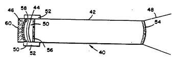
제1도는 본 발명에 따라 제조된 일체구조를 갖고 있는 평-쌍오목 형태의 Q-스위치식 레이저 공진기 어셈블리(10)을 도시한 것이다. 기본적으로, 어셈블리(10)은 레이저 봉(12), 다이 함침 아세테이트 쉬트(14)의 형태를 갖고 있는 Q-스위치 장치, 및 이를 통과하는 간접성 레이저 방사선의 펄스화 비임(18)을 조준하기 위한 출력 광학 결합기(16)으로 구성된다. 본 발명에 따르면, 쉬트(14)의 한면은 레이저 봉(12)의 단부면에 접착되어 있고, 대향면은 결합기(16)에 접착되어 있는데, 각 면은 거의 투명한 접착제(20)의 박층과 접착되어 있다. 알수 있는 바와 같이, 접착제(20)은 레이저 봉(12), 쉬트(14) 및 결합기(16)을 일체 강성 어셈블리(10)내에 함께 접착시킨다. 어셈블리(10)의 외부면 위에 놓여 있는 것, 더욱 상세하게 말하자면 접착제(20)을 포함하는 어셈블리(10)의 부분은 밀봉 물질(22)층이다. 밀봉 물질(22)는 주위 오염물로부터 하부 접착제(20)을 밀폐시키고, 부가적으로 더욱 양호한 구조적 강성을 어셈블리(10)에 제공한다.FIG. 1 shows a Q-switched
어셈블리(10)의 구성 부품을 더욱 상세하게 고찰하면, 레이저 봉(12)가 광학적으로 평평한 대향 단부면을 갖고 있는 거의 둥근 원통 형태를 갖는다는 것, 즉 레이저 봉(12)의 중심선이 각 단부면에 수직하다는 것을 알수 있다. 길이에 관련된 레이저 봉(12)의 반경은 본 분야에 종지된 바와 같이 다음 식, 즉 반경=길이/(1-g)(여기서, g는 곡선의 기하학적 형태의 관련된 상수이다)에 의해 주어진다. 알수 있는 바와 같이, 레이저 봉(12)의 길이는 소정 웅용의 특수 요구에 따라 한 실시예로부터 다른 실시예로 변할 수 있으므로, 반경이 비례적으로 변화되게 된다. 레이저 봉(12)는 전형적으로 네오디뮴-이트륨-알루미늄-가니트(Nd:YAG)와 같은 고 이득 레이징 물질로 구성되지만, 다른 유사한 레이징 물질이 양호하게 사용될 수도 있다. 레이저 방사선의 펄스화 비임(18)이 출력되는 단부면에 대향하는 레이저 봉(12)의 단부면은 전형적으로 95%보다 더 큰 반사 계수를 갖고 있는 고 반사 피막(24)으로 피막된다. 피막(24)에 대향하는 레이저 봉(12)의 단부면은 전형적으로 99.9%보다 더 많은 입사 방사선이 이를 통과하고 레이저 봉(12)으로부터 출력되게 하는 반사 방지 피막(26)으로 피막될 수 있다. 상술한 바와 같은 레이저 봉 단부면 피막의 사용 및 응용방법은 본 분야에 공지되어 있다.Considering the components of the
본 발명의 양호한 실시예에서, 다이 쉬트(14)는 이스트맨-코닥 코포레이션(Eastman-Kodak Corporation) 제품으로 Bis(4-dimethyl-aminodithiobenzil) 니켈(BDN)으로서 공지된 것과 같은 유기다이가 함침된 셀룰로스 아세테이트 막으로 구성되는데, 이 다이는 소정의 파장 범위의 경우에 소정 에너지 레벨 미만의 전자기(electromagnetic) 방사선을 거의 불투과시키고 소정의 에너지 레벨 이상의 방사선을 거의 투과시키는 특성을 갖고 있다. 그러므로, 다이 쉬트(14)는 댐프(damp)로서 작용하거나, 피막(24와 28)사이의 레이저 발진(oscillation)을 감소시키므로, 레이저 봉(12)내에서 고 반전 레벨이 달성될때까지 레이저 봉(12)가 레이징하는 것을 방지하는데, 전형적으로 이 달성된 반전 레벨은 통상적으로 다이 쉬트(14) 부재시에 레이저 봉(12)내에서의 레이징 작용을 야기시키는데 필요하게 되는 반전 레벨보다 더 크다. 레이저봉(12)내에서의 고 에너지 저장 레벨에 의해 특성화된 소정의 반전 임계값에서, 쉬트(14)는 신속히 투명 상태로 되거나, "표백(bleach)"되므로, Q 또는 저장된 에너지와 레이저 봉(12)내에서의 이 에너지의 소모율 사이의 관련성을 신속히 증가시키게 한다. 레이저 봉(12)의 Q의 이 신속한 증가는 레이저 봉(12)로부터 간섭성 레이저 방사선의 고전력 단-주기 펄스를 방출시키는데, 이 펄스는 현재 거의 투과성인 다이 쉬트(14)를 통과하게 된다. 이러한 펄스를 전형적으로 "거대 펄스(giant pulse)"라고 한다. 알수 있는 바와 같이, 다이 쉬트(14)는 스위치, 특히 Q-스위치로서 고려될 수 있다. 본 발명의 양호한 실시예의 Q-스위치가 다이 쉬트(14)의 형태로 되어 있는 것으로서 본 명세서내에 기술되어 있지만, 전기 광학 스위치, 음향 광학 스위치, 및 우라늄 도우프 유리와 같은 "유리(glass)"스위치와 같은 다양한 적합한 형태들이 사용될 수도 있다.In a preferred embodiment of the present invention, the
어셈블리(10)의 제3부품은, 본 발명의 이 실시예에서 레이저 봉(12)로부터 출력되어 쉬트(14)를 통하는 방사선 펄스에 대해 부분 반사성인 결합기(16)이다. 결합기(16)은 적합한 피막(28)을 결합기(16)의 내부 오목면에 인가함으로써 부분 반사성으로 되는데, 부분 반사성 면은 레이저 봉(12)의 레이징 작용을 유지시키는데 필요한 에너지 궤환량을 제공하게 된다. 또한, 내부 오목면은 다이 쉬트(14)용 구조적 지지부로서도 작용한다. 부수적으로, 이 내부면에서는 본 분야에 공지되어 있는 바와 같이 레이저 봉(12) 및 봉입 구조물(제1도에는 도시되어 있지 않음)로 구성되는 공진기 공동의 전체 안정도를 결정하는 오목 곡선부가 제공된다. 결합기(16)의 외부 볼록면은 이 면이 펄스화 비임(18)에 대해 거의 투과성을 갖도록 반사 방지 피막(30)으로 적합하게 피막된다. 부수적으로, 이 외부 볼록면은 펄스화 비임(18)의 발산의 구형(spherical) 성분을 보정하는 곡선부를 갖고 있으므로, 이 발산을 이상적 평-평면값으로 보정하게 된다. 결합기(16)은 적합한 광학 물질로 구성되는데, 이 특수 물질은 의도된 펄스 반복율 및 그외의 다른 응용 특수 파라메터에 따라 선택된다.The third part of the
본 발명의 목적에 따르면, 레이저 봉(12), 쉬트(14) 및 결합기(16)은 일체구조로 된 Q-스위치식 레이저공진기를 형성하기 위해서 상술한 거의 투명한 접착제(20)으로 서로 접착된다. 접착제(20)은 감쇠없이 레이저 방사선의 고 전력 펄스에 견딜 수 있는 것을 특징으로 하는 하텔 인더스트리이즈(Hartel Industries)에 의해 제조된 형태로 될수 있다. 부수적으로, 접착제(20)은 쉬트(14)의 광학 인덱스와의 피막(26)의 광학 인덱스(index)의 정합, 및 피막(28)의 광학 인덱스와의 쉬트(14)의 광학 인덱스의 정합을 제공하므로, 전형적으로 본래 빈약한 다이 쉬트(14)의 광학 표면 질을 보정하게 된다.According to the object of the present invention, the
상술한 바와 같이, 어셈블리(10)에 더욱 큰 구조적 강도를 제공하기 위해서, 밀봉 물질(22)층이 접착제(20)에 의해 형성된 접착성 접착제 밑에 놓여 있는 어셈블리(10)의 외부면의 일부분에 인가된다. 큰 강도를 제공하는 것 외에, 물질(22)는 또한 접착제(20) 및 다이 쉬트(14)용 밀폐물로서 작용하므로, 주위 오염물의 유입을 방지하게 된다. 물질(22)는 소정의 적합한 형태로 될수 있는데, 한가지 이러한 형태는 암스트롱 코포레이션(Armstrong Corporation)에 의해 제조되고, A-12로서 공지되어 있다.As noted above, in order to provide greater structural strength to the
제2도를 참조하면, 역시 본 발명에 따라 구성되는 제2형태의 일체 Q-스위치식 레이저 공진기 어셈블리(40)이 도시되어 있다. 어셈블리(40)은 평-볼록-오목형 형태로 되어 있고, 여기서 펄스화 비임(48)은 레이저 봉(42)의 단부면으로부터 출력되는데, 이 단부면은 어셈블리(40)의 안정도를 증가시키도록 계산되는 반경을 갖고 있다. 부수적으로, 어셈블리(40)은 형태 및 기능이 제1도의 다이 쉬트(14)와 유사한 다이 쉬트(44)로 구성된다. 반사성 결합기(46)은 쉬트(44)에 인정하여 배치된 표면을 갖고 있는데, 이 표면은 오목곡선부를 갖고 있다. 결합기(46)의 대향면(60)은 편평하고, 어셈블리(40)의 중심선에 수직이다.Referring to FIG. 2, there is shown an integrated Q-switched
레이저 봉(42), 쉬트(44), 및 결합기(46)은 본 발명에 따른 제1도의 실시예에 기술된 것과 같은 접착제(50) 박 층으로 서로 접착된다. 밀봉 물질(52)의 피막은 하부 쉬트(44) 및 접착제(50)을 밀폐시키고 더 큰 구조적 강도를 제공하기 위해 쉬트(44)에 인접한 어셈블리(40)의 외부면의 일부분상에 인가된다.The
펄스화 비임(48)이 출력되는 레이저 봉(42)의 단부면은 반사 방지 피막(54)층으로 피막되고, 접착제(50)의 인접한 평평한 단부는 접착제(50)층의 광학 인덱스를 정합시키기 위해서 광학 인덱스 정합 피막(56)으로 처리된다. 반사기(46)의 오목면은 고 반사 피막(58)층으로 피막되고, 피막(58)에 대향한 평면(60)은 처리되지 않은 채이거나, 프로스트(frost)되거나, 부분적으로 처리되지 않은 채로 있게 되므로, 어셈블리(40)내의 반사부의 일부가 이를 통해 샘플될 수 있다.The end face of the
어셈블리(40)의 동작은 제1도의 어셈블리의 동작과 유사하다. 즉, 다이 쉬트(44)는 정상 에너지 저장률보다 더 큰 저장률이 레이저 봉(42)내에서 달성될때까지 레이저 봉(4)의 레이징 작용을 방지하는데, 이때 쉬트(44)는 거의 투명하게 되므로, 간섭성 레이저 방사선의 펄스가 레이저 봉(42)로부터 출력되는 쉬트(44)를 통과하게 한다. 본 발명의 이 실시예에서, 레이저 방사선의 펄스는 방사선의 강한 펄스화 비임(48)로서 방출되도록 결합기(46)의 반사성 오목면으로부터 반사되므로, 쉬트(44) 및 레이저 봉(42)를 1회 이상 통과하게 된다.The operation of the
Q-스위치 및 결합기가(제2도에서와 같이) 방사선이 출력되는 단부에 대향한 레이저 봉의 단부에 배치되는 Q-스위치식 레이저 공진기는 전형적으로 펄스화 비임의 출력 전력이 Q-스위치 물질 또는 결합기의 구조적 일체성에 악 영향을 미치기에 충분한 응용시에 사용된다. 그러나, 실제로는, 제1도 및 제2도에 도시한 2가지 형태의 Q-스위치식 레이저 공진기들의 동작 이론은 동일하다. 부수적으로, 본 분야에 공지되어 있는 바와 같이, 매우 다양한 여러가지 형태의 Q-스위치식 레이저 공진기들이 존재할 수 있는데, 이들은 코너(corner) 반사형 또는 평-평면 형과 같은 사용된 출력 결합기 또는 반사성 결합기의 형태면에서 서로 다르다. 그러나, 각각의 다양한 형태의 Q-스위치식 레이저 공진기는 본 발명의 방법에 의한 일체 형태로 구성될 수 있으므로, 상술한 바와 같은 이로부터 유도된 다수의 장점들을 발생시키게 된다.Q-switched laser resonators in which the Q-switch and combiner are arranged at the end of the laser rod opposite the end where the radiation is output (as in FIG. 2) typically have an output power of the pulsed beam of Q-switch material or combiner. It is used in applications where it is sufficient to adversely affect its structural integrity. In practice, however, the operating theory of the two types of Q-switched laser resonators shown in FIGS. 1 and 2 is the same. Incidentally, as is known in the art, there can be a wide variety of different types of Q-switched laser resonators, which can be used for the output coupler or reflective coupler used, such as corner reflective or flat-plane type. Different in form. However, each of the various types of Q-switched laser resonators can be configured integrally by the method of the present invention, resulting in a number of advantages derived therefrom as described above.
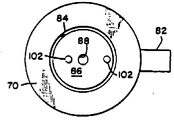
제3a도 및 제3b도 내에 도시한 바와 같이, 정렬 및 제조 고정부(70)은 전형적으로 알루미늄으로 구성되고, 구성중에 레이저 어셈블리(73)을 꼭 맞게 포함하기 위해 동근 원통 형태를 갖고 있는 중앙 배치 채널(72)를 갖추고 있다. 어셈블리(73)은 레이저 봉(74), 다이 쉬트(76)의 형태로 된 Q-스위치 장치, 및 광학결합기(78)로 구성된다. 고정부(70)의 외부면을 통해 형성된 다수의 측 채널(80)은 채널(72)와 수직으로 통하는데, 이 측 채널(80)은 레이저 봉 지지 구조물(82)가 이것을 자유롭게 통과할 수 있는 채널(72)내에 삽입될 수 있도록 거의 장방형 형태로된 외부 개구를 각각 갖고 있다. 실제로, 다수의 개구(80)들중 1개의 개구만이 소정시기에 지지부(82)를 포함하게 되는데, 지지부(82)를 포함하게 되는 개구(80)의 선택은 레이저봉(74)의 길이에 의해 결정된다. 그러므로, 길이가 변하는 다수의 레이저 봉들이 간단하고 저렴한 효과적인 방식으로 고정부(70)에 의해 수용될 수 있다. 지지부(82)는 전형적인 현미경 슬라이드와 같은 거의 장방형 표면 형태 및 얇은 장방형 단면 형태를 갖고 있다. 챔버(chamber,72)보다 직경이 더 큰 제2둥근 원통형 챔버(84)가 챔버(72)위에 배치되고 이 챔버(72)와 통하게 된다. 챔버(84)는 정렬 헤드(86)이 이 챔버(84)내에 끼워질 수 있게 하기 위해서 제공된다. 헤드(86)은 전형적으로 알루미늄으로 구성되고, 이를 통해 형성된 중앙 배치 애퍼츄어(88)을 갖고 있는 둥근 원통 형태로 되어 있다. 애퍼츄어(88)은 결합기(78)의 단부 부분을 싸기 위해 증가된 직경의 원통형 쉘프(89)내에서 종단된다. 제3A도내에서 알수 있는 바와 같이, 챔버(72)는 지지부(82)의 두께 및 어셈블리(73)의 전체 길이와 함께, 결합기(78)이 챔버(84)내로 상향 연장되고 쉘프(89)내에 셋트된 정도의 깊이를 갖는다. 그러므로, 헤드(86)은 안착되고, 하부 결합기(78), 다이 쉬트(76), 레이저 봉(74) 및 지지부(84)에 의해 지지된다.As shown in FIGS. 3A and 3B, the alignment and
어셈블리(73)의 적합한 구성방법은 다음과 같다. 단부면들이 적합하게 피막되어 있는 레이저 봉(74)는 먼저 고정부(70)의 챔버(72)내에 삽입된다. 고정부(70)은 레이저 봉(74)가 그위에 수직으로 배치되는 광학대와 같은 수평 강성 작업면(90)상에 지지되는데, 레이저 봉(74)의 중심선은 수평 작업면(90)에 수직하게 된다. 점성 컨시스턴스(viscous consistency)를 갖고 있는 제1접착제층(92)는 레이저 봉(74)의 상단부면에 제공되는데, 이 층(92)는 전형적으로 1/10000 내지 1/1000인치(2.54×10-4내지 2.54×10⁻³cm)의 두께를 갖고 있다. 그다음, 다이 쉬트(76)이 층(92)상에 배치되는데, 쉬트(76)의 하부면은 레이버 봉(74)의 상부면과 거의 평행하게 배치된다. 제2점성 접착제층(94)는 쉬트(76)의 상부면에 제공되는데, 이 제2층(94)는 제1층(92)의 두께와 필적할 만한 두께를 갖고 있다. 다음에, 출력 결합기(78)이 접착제층(94)상에 배치된다. 최종적으로, 헤드(86)은 결합기(78)의 상부면상에 배치되는데, 헤드(86)의 중량은 하부 결합기(78) 및 쉬트(76)이 레이저 봉(74)의 상단부면을 향해 밀어지게 작용한다.A suitable configuration of the
접착제층(92 및 94)가 약 2시간 이내에 셋트되므로 경화되어 구부러지지 않게 되기 때문에, 구성 완료 직후에 어셈블리(73)을 광학적으로 정렬시킬 필요가 있다. 이 광학 정렬은 평면 반사성 반사경(98)과 함께, 구조가 공지되어 있는 간섭계(96)으로 실행된다. 대부분의 공지된 간섭계들이 광학대와 같은 작업면에 관련하여 거의 수평인 평면내에 배치될때 사용되도록 설계되기 때문에 반사경(98)이 요구된다. 고정부(70)이 어셈블리(73)을 작업면(90)에 관련하여 수직인 평면내에 배향시키기 때문에, 반사경(98)은 수평으로 배치된 간섭계(96)으로부터 발생되는 정렬 상태의 비임(100)을 90°로 반사시키도록 배치된다. 그러므로, 비임(100)은 결합기(78)의 상부면으로 입력되게 되는데, 이 비임(100)은 헤드(86)내에 제공된 애퍼츄어를 통과한다. 이 비임(100)은 어셈블리(73)을 통과하여, 레이저 봉(74)가 이렇게 피막되는 경우에 레이저 봉(74)의 대향단부에서의 반사 피막으로부터, 또는 지지부(82)의 반사면으로부터 반사된다. 비임(100)은 반사후에 다시 어셈블리(73)을 통과하고, 반사경(98)에 의해 다시 한번 반사되며, 간섭계(96)으로 입력되도록 복귀된다.Since the
간섭계(96)의 작용은, 본 분야에 공지되어 있는 바와 같이, 출력 광선 비임의 파장의의 상(phase)을 복귀 광선 비임의 과장의 상과 비교함으로써 다수의 동심 간섭 링을 발생시키는 것이다. 본 발명의 방법으로, 링들은 어셈블리(73)의 구성 부품들의 정렬도(degree of alignment)를 나타낸다. 제3도에 도시된 바와 같은 정렬방법으로, 어셈블리(73)은 간섭계(96)에서 관찰된 동심 간섭링의 중심이 레이저 봉(74)의 중심으로부터의 레이저 봉(74)의 직경의 약 10%인 거리만큼 떨어져 있을때 양호하게 정렬되는 것으로 고려된다.The function of the
이 정렬도를 달성하기 위해, 다수의 작은 추(102)(이들중 2개의 추는 제3a도 및 제3b도내에 도시되어 있다)는 헤드(86)의 상부면상의 여러 지점에 배치될 수 있다. 각 추(102)의 목적은 헤드(86)상에 하향힘을 발생시키기 위한 것인데, 이 힘은 하부 결합기(78) 및 쉬트(76)으로 전달된다.To achieve this degree of alignment, a number of small weights 102 (two of which are shown in FIGS. 3A and 3B) may be placed at various points on the top surface of the
알수 있는 바와 같이, 접착제층(92 및 94)가 셋트되거나 경화되기 전에, 이 층들은 점성 상태로 유지된다. 그러므로, 쉬트(76) 및 결합기(78)은 이 점성 접착제층(92 및 94)상에 "부동 상태(floating)"인 것으로 생각될 수 있다. 이 부품들상에 1가지 또는 그 이상의 하향 힘을 발생시킴으로써, 이들이 평면 배향은 레이저 봉(74)의 단부면에 관련하여 변경될 수 있다. 그러므로, 간섭계의 조작자는 간섭 링 패턴을 관찰함으로써, 어셈블리(73)의 정렬이 달성될때까지 추(102)의 수 및 위치를 조정한다. 양호한 정렬도가 얻어지면, 접착제층(92 및 94)는 방해받지 않은 셋팅 공정을 완료하게 되는데, 이때 쉬트(76) 및 결합기(78)은 어셈블리(73)의 정렬을 보장하도록 레이저 봉(74)의 인접 단부면에 관련하에 양호한 위치내에 견고하게 유지된다. 접착제 셋팅 기간이 만료된 후 때때로, 어셈블리(73)은 고정부(70)으로부터 제거되고, 접착제층(92 및 94)를 완전 경화시키기 위해서 전형적으로 1주 동안 수직 위치로 저장되므로, 이들의 최대 경도를 달성하게 된다.As can be seen, before the
이 경화 기간후, 상술한 밀봉 물질층(제3A도 및 제3B도 내에는 도시되어 있지 않음)이 제공되므로, Q-스위치식 레이저 어셈블리(73)의 구성을 완료하게 된다.After this curing period, the above-described sealing material layer (not shown in FIGS. 3A and 3B) is provided, thereby completing the construction of the Q-switched
층(92 및 94)가 어셈블리(73)으로부터 발생되는 방사선이 광학로(optical Path)의 일부를 형성하기 때문에, 이 층(92 및 94)의 균질성(uniformity)은 어셈블리(73)의 구성중의 중요 목적이다. 알수 있는 바와 같이, 고정부(70)의 수직 배치는 이 균일성 목적을 달성하는데 관련된 어셈블리(73)의 구성시에 몇가지 장점들을 제공한다. 한가지 장점은 접착제층(92 및 94)가, 점성 상태에 있는 동안, 중력에 의해 균일하게 작용된다는 것이다. 그러므로, 각 층(92 및 94)의 두께는 각 접착제층상에 균일하게 작용하는 중력의 평준화 효과(leveling effect)와 함께 헤드(86)의 중량에 의해 발생된 하향 힘으로 인해 거의 균일하게 형성된다. 고정부(70)이 수직 배치에 의해 얻어질 다른 장점은 모세관 작용으로 인한 접착제층(92 및 94)의 균일한 확산이 촉진되므로, 레이저 봉(74), 쉬트(76) 및 결합기(78)의 인접면들과의 층(92 및 94)의 미세일치(microcon-formance) 를 보장하여 준다.Since the
제4도를 참조하면, 본 발명에 따라 구성된 Q-스위치식 레이저 공진기(112), 및 공진기(12)에 여기 방사선 소오스(source of excitation radiation)를 제공하기 위해 공진기(112)에 인접하여 배치된 플래쉬 램프(114)로 구성되는 레이저 시스템(110)이 도시되어 있다. 공진기(112) 및 플래쉬 램프(114)는 반사기 공동(116)내에 봉입되는데, 이 공동(116)은 거의 모든 방사선이 공진기(112)상에 충돌하게 되도록 플래쉬 램프(114)로부터 발생되는 방사선을 반사시키게 된다. 공동(116)은 지지부(118)에 의해 각 단부에 지지되는데, 이 지지부(118)은 레이저 방사선의 펄스화 비임(120)을 이를 통해 발생시키게 하기 위해 내부에 형성된 개구를 갖고 있다. 동작시에, 전극(122) 쌍들은 적합한 전압을 인가시킴으로써 활성화 되므로, 플래쉬 램프(114)내의 개스(도시하지 않음)를 이온하시키게 된다. 전극 활성화는 플래쉬 램프(114)에 의해 발생될 전자방사선이 고강도 버스트(burst) 또는 플래쉬를 발생시킨다. 방사선의 일부는 레이저 봉(132)상에 입사되고 내부에 흡수되며, 반사성 공동(116)의 벽 상에 충돌하는 방사선은 흡수되도록 레이저 봉(132)내로 다시 반사된다. 레이저 봉(132)의 물리적 특성으로 인해, 레이저 봉(132)는 형광하기 시작하게 되므로, 플래쉬 램프(114)로부터 흡수된 방사선을 재발생시키게 된다. 재발생된 방사선의 일부는 통계학적으로 공진된(112)의 광학축(124)와 일치하여 보내지게 되므로, 공지된 메카니즘에 의해 공진기(112)의 레이징 작용을 개시시키게 된다.4, a Q-switched
알수 있는 바와 같이, 본 발명의 단일화 Q-스위치식 레이저 공진기는 시스템(110)내에 사용될때 몇가지 장점들을 제공한다. 한가지 이러한 장점은 간편하고 비교적 간단한 구조를 갖고 있는 시스템이 달성될 수 있다는 것인데, 이때 시스템(110)내에 수용되기 위해 종래 기술의 지지 광학대가 필요하지 않게 된다. 부수적으로, 시스템(110)은 진동 및 기계적 충격의 영향을 덜 받으므로, 종래 기술의 공진기로 구성된 시스템에해롭게 되는 주의 환경내에 사용될 수 있다. 부수적인 다른 장점은 전체 시스템(110)의 구성 및 유지 비용이 감소된다는 것이다.As can be seen, the single Q-switched laser resonator of the present invention provides several advantages when used within the
지금까지, 본 발명의 장치 및 방법의 양호한 실시예에 대해서 기술하였지만, 본 분야에 숙련된 기술자들은 본 발명의 원리 및 범위를 벗어나지 않고서 본 발명을 여러가지 형태로 변경 및 변형시킬 수 있다.While the preferred embodiments of the apparatus and method of the present invention have been described so far, those skilled in the art can change and modify the present invention in various forms without departing from the principles and scope of the present invention.
Claims (18)
Applications Claiming Priority (3)
| Application Number | Priority Date | Filing Date | Title |
|---|---|---|---|
| US06/868,381 US4682336A (en) | 1986-05-29 | 1986-05-29 | Q-switched laser resonator of integral construction |
| US868381 | 1986-05-29 | ||
| PCT/US1987/000927 WO1987007446A2 (en) | 1986-05-29 | 1987-04-24 | Q-switched laser resonator of integral construction |
Publications (2)
| Publication Number | Publication Date |
|---|---|
| KR880701478A KR880701478A (en) | 1988-07-27 |
| KR910002240B1 true KR910002240B1 (en) | 1991-04-08 |
Family
ID=25351566
Family Applications (1)
| Application Number | Title | Priority Date | Filing Date |
|---|---|---|---|
| KR1019880700088A KR910002240B1 (en) | 1986-05-29 | 1987-04-24 | Q - switched laser resonator of integral construction |
Country Status (8)
| Country | Link |
|---|---|
| US (1) | US4682336A (en) |
| EP (1) | EP0267260A1 (en) |
| JP (1) | JPS63503424A (en) |
| KR (1) | KR910002240B1 (en) |
| ES (1) | ES2003815A6 (en) |
| IL (1) | IL82404A (en) |
| TR (1) | TR25371A (en) |
| WO (1) | WO1987007446A2 (en) |
Families Citing this family (10)
| Publication number | Priority date | Publication date | Assignee | Title |
|---|---|---|---|---|
| JP3066966B2 (en) * | 1988-02-29 | 2000-07-17 | ソニー株式会社 | Laser light source |
| US4877952A (en) * | 1988-10-11 | 1989-10-31 | American Telephone And Telegraph Company | Faser cavity optical memory with optical storage and readout |
| US5117433A (en) * | 1989-11-27 | 1992-05-26 | Hitachi, Ltd. | Second harmonic generator for obtaining an aberration free plane wave and information processing system using the same |
| DE4318616C2 (en) * | 1992-08-06 | 1997-07-03 | Zeiss Carl Fa | Compact unstable laser resonator |
| US5251221A (en) * | 1992-08-10 | 1993-10-05 | Hughes Aircraft Company | Self aligning intracavity Raman laser |
| US5652756A (en) * | 1995-01-20 | 1997-07-29 | Hughes Electronics | Glass fiber laser system using U-doped crystal Q-switch |
| US5557624A (en) * | 1995-01-20 | 1996-09-17 | Hughes Aircraft Company | Laser system using U-doped crystal Q-switch |
| US5724372A (en) * | 1995-01-20 | 1998-03-03 | Hughes Electronics | Diode-pumped laser system using uranium-doped Q-switch |
| US5654974A (en) * | 1995-10-11 | 1997-08-05 | Hughes Electronics | Passive Q-switch using multiple saturable absorber materials |
| CN112382920B (en) * | 2020-11-28 | 2021-07-23 | 河南工程学院 | Low-voltage laminated lithium niobate electro-optical Q switch |
Family Cites Families (5)
| Publication number | Priority date | Publication date | Assignee | Title |
|---|---|---|---|---|
| US3500234A (en) * | 1966-07-07 | 1970-03-10 | Rca Corp | Unitary q-switch laser device |
| US3566302A (en) * | 1966-09-23 | 1971-02-23 | Spectra Physics | Laser optical cavity and alignment method |
| US3764220A (en) * | 1971-07-30 | 1973-10-09 | Nasa | Alignment apparatus using a laser having a gravitationally sensitive cavity reflector |
| GB1566716A (en) * | 1977-03-15 | 1980-05-08 | Gen Electric Co Ltd | Laser resonators and their manufacture |
| US4359777A (en) * | 1981-01-22 | 1982-11-16 | The United States Of America As Represented By The Secretary Of The Army | High efficiency transversely excited electrodeless gas lasers |
-
1986
- 1986-05-29 US US06/868,381 patent/US4682336A/en not_active Expired - Lifetime
-
1987
- 1987-04-24 EP EP87903510A patent/EP0267260A1/en not_active Ceased
- 1987-04-24 WO PCT/US1987/000927 patent/WO1987007446A2/en not_active Application Discontinuation
- 1987-04-24 KR KR1019880700088A patent/KR910002240B1/en not_active IP Right Cessation
- 1987-04-24 JP JP62503328A patent/JPS63503424A/en active Granted
- 1987-05-01 IL IL82404A patent/IL82404A/en unknown
- 1987-05-21 TR TR87/0351A patent/TR25371A/en unknown
- 1987-05-28 ES ES8701562A patent/ES2003815A6/en not_active Expired
Also Published As
| Publication number | Publication date |
|---|---|
| IL82404A0 (en) | 1987-11-30 |
| TR25371A (en) | 1993-01-08 |
| EP0267260A1 (en) | 1988-05-18 |
| WO1987007446A2 (en) | 1987-12-03 |
| US4682336A (en) | 1987-07-21 |
| JPH0530314B2 (en) | 1993-05-07 |
| KR880701478A (en) | 1988-07-27 |
| IL82404A (en) | 1991-06-30 |
| WO1987007446A3 (en) | 1988-01-14 |
| JPS63503424A (en) | 1988-12-08 |
| ES2003815A6 (en) | 1988-11-16 |
Similar Documents
| Publication | Publication Date | Title |
|---|---|---|
| US4910746A (en) | Multiple crystal pumping cavity laser with thermal and mechanical isolation | |
| Kogelnik et al. | Stimulated emission in a periodic structure | |
| US4360925A (en) | Laser employing an unstable resonator having an output transmissive mirror | |
| US3725810A (en) | Optical stimulated emission devices employing split optical guides | |
| US3774121A (en) | Wavelength selective laser apparatus | |
| US3975693A (en) | Dual function laser for space laser communications | |
| US4156209A (en) | Lens free of back focal points for use with high power light beams | |
| KR910002240B1 (en) | Q - switched laser resonator of integral construction | |
| NO843903L (en) | FIBEROPTICAL AMPLIFIER | |
| US3924201A (en) | Laser apparatus employing mechanical stabilization means | |
| US3674340A (en) | Device for improving the optical qualities of a laser beam | |
| US5359622A (en) | Radial polarization laser resonator | |
| US4118675A (en) | Laser tuning with an acousto-optic lens | |
| US3675157A (en) | Tunable laser in a sensitized transparent material including an internal resonator and optical guide | |
| Digonnet et al. | 1.064-and 1.32-µm Nd: YAG single crystal fiber lasers | |
| US5432811A (en) | Laser rod with polyhedron shaped ends | |
| US3747021A (en) | Wide range continuously tunable thin film laser | |
| US3979696A (en) | Laser pumping cavity with polycrystalline powder coating | |
| US6160934A (en) | Hollow lensing duct | |
| US4860301A (en) | Multiple crystal pumping cavity laser with thermal and mechanical isolation | |
| US3500234A (en) | Unitary q-switch laser device | |
| NO309218B1 (en) | Self-aligning intracavity Raman lasers | |
| US3860888A (en) | Time-sharing two frequency laser | |
| US5513205A (en) | End-pumping laser configuration utilizing a retroreflector as an input coupler | |
| US5371758A (en) | Apparatus for efficient, more uniform high power excitation of a dye media optical amplifier |
Legal Events
| Date | Code | Title | Description |
|---|---|---|---|
| A201 | Request for examination | ||
| E902 | Notification of reason for refusal | ||
| G160 | Decision to publish patent application | ||
| E701 | Decision to grant or registration of patent right | ||
| GRNT | Written decision to grant | ||
| FPAY | Annual fee payment |
Payment date: 19990403 Year of fee payment: 9 |
|
| LAPS | Lapse due to unpaid annual fee |