KR900007800B1 - Efficient phase conjugate laser - Google Patents
Efficient phase conjugate laser Download PDFInfo
- Publication number
- KR900007800B1 KR900007800B1 KR1019870701042A KR870701042A KR900007800B1 KR 900007800 B1 KR900007800 B1 KR 900007800B1 KR 1019870701042 A KR1019870701042 A KR 1019870701042A KR 870701042 A KR870701042 A KR 870701042A KR 900007800 B1 KR900007800 B1 KR 900007800B1
- Authority
- KR
- South Korea
- Prior art keywords
- laser
- radiation
- gain element
- phase
- optical path
- Prior art date
Links
Images


Classifications
-
- H—ELECTRICITY
- H01—ELECTRIC ELEMENTS
- H01S—DEVICES USING THE PROCESS OF LIGHT AMPLIFICATION BY STIMULATED EMISSION OF RADIATION [LASER] TO AMPLIFY OR GENERATE LIGHT; DEVICES USING STIMULATED EMISSION OF ELECTROMAGNETIC RADIATION IN WAVE RANGES OTHER THAN OPTICAL
- H01S3/00—Lasers, i.e. devices using stimulated emission of electromagnetic radiation in the infrared, visible or ultraviolet wave range
- H01S3/23—Arrangements of two or more lasers not provided for in groups H01S3/02 - H01S3/22, e.g. tandem arrangements of separate active media
- H01S3/2308—Amplifier arrangements, e.g. MOPA
- H01S3/2325—Multi-pass amplifiers, e.g. regenerative amplifiers
- H01S3/2333—Double-pass amplifiers
-
- H—ELECTRICITY
- H01—ELECTRIC ELEMENTS
- H01S—DEVICES USING THE PROCESS OF LIGHT AMPLIFICATION BY STIMULATED EMISSION OF RADIATION [LASER] TO AMPLIFY OR GENERATE LIGHT; DEVICES USING STIMULATED EMISSION OF ELECTROMAGNETIC RADIATION IN WAVE RANGES OTHER THAN OPTICAL
- H01S3/00—Lasers, i.e. devices using stimulated emission of electromagnetic radiation in the infrared, visible or ultraviolet wave range
- H01S3/10—Controlling the intensity, frequency, phase, polarisation or direction of the emitted radiation, e.g. switching, gating, modulating or demodulating
- H01S3/10076—Controlling the intensity, frequency, phase, polarisation or direction of the emitted radiation, e.g. switching, gating, modulating or demodulating using optical phase conjugation, e.g. phase conjugate reflection
Abstract
내용 없음.No content.
Description
이하, 첨부 도면을 참조하여 본 발명에 대해서 상세하게 기술하겠다.Hereinafter, the present invention will be described in detail with reference to the accompanying drawings.
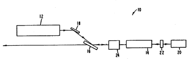
제1도는 본 발명의 원리에 따른 고 추출 효율 레이저 장치를 도시한 도면이다.1 illustrates a high extraction efficiency laser device in accordance with the principles of the present invention.
제2도는 다수의 이득 소자 및 중요한 영상 원래를 사용하는 본 발명에 따른 고 추출 효율 레이저를 도시한 도면이다.Figure 2 shows a high extraction efficiency laser in accordance with the present invention using multiple gain elements and significant image origins.
제3도는 위상 공액 반사기의 선택적인 실시예를 도시한 도면이다.3 shows an alternative embodiment of a phase conjugated reflector.
배경background
본 발명은 레이저에 관한 것으로, 더욱 상세하게 말하자면 파두왜곡(wavefront distortion)을 보상하기위해 위상 공액(phase conjugate) 반사기를 사용하는 레이저 발진기 증폭기에 관한 것이다.FIELD OF THE INVENTION The present invention relates to lasers and, more particularly, to laser oscillator amplifiers that use phase conjugate reflectors to compensate for wavefront distortion.
레이저 및 레이저 시스템은 몇가지 파두 왜곡 및 스팩트럼 폭 확대 소오스의 영향을 받는다. 열 응력 또는 변화도, 진동, 또는 수차(aderration)에 의해 야기된 영향들은 레이저를 횡단하는 (traversing) 방사선파두 내의 왜곡에 기여하는 문제점들이다. 부수적으로, 열 효과는 광학 소자들에 대한 정상 상태 동작의 열평형에 도달되기 전에, 시동(start-up)중의 동작에 대한 큰 과도(transient) 효과를 야기시킨다. 이것은 펄스화 레이저 및 CW레이저가 버스트(burst) 내에서 동작되는 경우에 심각한 문제점이 될 수 있는네, 그 이유는 과도 기간이 전체 레이저 동작 싸이클의 상당한 퍼센테이지를 포함하기 때문이다.Lasers and laser systems are affected by several wave distortion and spectral widening sources. The effects caused by thermal stress or gradients, vibrations, or aberrations are problems that contribute to distortion in radiation heading traversing the laser. Incidentally, the thermal effect causes a large transient effect on the operation during start-up before reaching thermal equilibrium of steady state operation for the optical elements. This can be a serious problem when pulsed lasers and CW lasers are operated in bursts, since the transient period involves a significant percentage of the entire laser operating cycle.
파두 왜곡은 레이저의 성능을 저하시키고, 자체는 빈약한 에너지 추출 효율 및 비임 발산(beam divergence)을 나타낸다. 요구된 출력 비임 질(quality) 및 전력 레벨에 따라, 레이저 내부의 부품들내의 파두 왜곡은 레이저를 소정의 응용용으로 부적합하게 만들 수 있다. 이것은 거의 회절이 제한된 레이저 출력이 요구되는 진보된 통신 또는 트랙킹 시스템의 경우에 사실이다. 더우기, 정상 상태 동작이 종래의 장치에 의해 만족될 수 있더라도, 고 전력 또는 고 에너지 밀도 레이저내의 열효과는 레이저 소자들이 열평형을 획득할 때 정상 상태 동작전의 초기 시동 기간 중에 불만족스러운 성능을 여전히 발생시킨다.The wave distortion degrades the laser's performance and itself shows poor energy extraction efficiency and beam divergence. Depending on the required output quality and power level, wave distortion in the components inside the laser may render the laser unsuitable for certain applications. This is true for advanced communication or tracking systems where near diffraction limited laser power is required. Moreover, even if steady state operation can be satisfied by conventional devices, thermal effects in high power or high energy density lasers still produce unsatisfactory performance during the initial startup period before steady state operation when the laser elements achieve thermal equilibrium. Let's do it.
특수화된 역-반사기(retro-reflector) 및 변형가능한 반사경을 포함하는 파두 왜곡을 제거하거나 방지하기 위한 몇가지 기술들이 제안되어 왔다. 전형적인 고상(solid state) 레이저 로드(rod)내에서, 펌핑(pumping) 에너지에 의해 발생된 열 변화도는 네가티브(negative)렌즈로 수정될 수 있는 포지티브렌징(positive lensing)으로서 공지된 효과를 발생시킨다. 그러나, 과도 상태의 경우에, 변화 렌징을 동적으로 보상하기 위해 기계적 드라이브(drive)들이 사용되어야 한다. 이것은 어느 정도 성공적으로 사용되어 왔지만, 몇가지 결점들이 있다. 첫째, 슬래브(slab) 기하학적 형태 레이저 이득(gain) 매질과 같은 방사상 대칭이 아닌 기하학적 형태의 경우에, 매질 렌징 효과는 간단한 렌즈의 효과가 아니고, 보상하기 위해 복잡한 렌즈 구조물을 필요로 한다. 둘째, 소정의 "동적"렌즈시스템은 고속 징밀 폐쇄-루우프 검출 및 조정을 필요로 한다. 이것은 대형 레이저 시스템내의 전자 제어식, 기계 구동식 변형가능하거나 가요성이 있는 반사경 및 궤환 루우프 또는 서보(servo) 시스템의 개발을 유도하였다. 명백한 바와같이, 이것은 레이저 또는 레이저 시스템이 요구된 것보다 더욱 복잡하고 가격이 비싸며 정렬 에러가 발생하기 쉽게 만든다. 또한, 이 해결 방법은 다수의 응용을 적합하게 보상하기 위해 과도 효과를 간단히 정합(match)시킬 수 없는 동작 응답(속도) 제한을 여전히 갖는다. 어떠한 기계적 시스템도 진보된 거의 회절이 제한된 레이저용으로 요구된 보상 레벨을 달성하지 못하였다.Several techniques have been proposed for eliminating or preventing wave distortion, including specialized retro-reflectors and deformable reflectors. In a typical solid state laser rod, the thermal gradient generated by the pumping energy produces an effect known as positive lensing that can be corrected with a negative lens. . However, in the case of transients, mechanical drives must be used to dynamically compensate for varying lensing. It has been used to some extent, but there are some drawbacks. First, in the case of non-radially symmetrical geometries such as slab geometry laser gain media, the medium lensing effect is not a simple lens effect, but requires a complex lens structure to compensate. Second, certain "dynamic" lens systems require fast dense closed-loop detection and adjustment. This has led to the development of electronically controlled, mechanically driven deformable or flexible reflectors and feedback loops or servo systems in large laser systems. As is apparent, this makes the laser or laser system more complex, expensive, and more prone to misalignment than required. In addition, this solution still has an operating response (speed) limit that simply cannot match the transient effects to adequately compensate for many applications. No mechanical system has achieved the level of compensation required for advanced nearly diffractive lasers.
부수적으로, 대부분의 응용들은 동작의 초기 워밍-업 또는 시동중에도 효율적인 동작을 필요로 하거나 요구한다. 이전에 제한된 정교한 기계적 열 렌징 보상 시스템은 과도 워밍-업 상태하에서 효율면에서 양호한 성능을 달성하지 못하였다. 회절 제한 성능은 정상 상태 조건하에서 실험용 레이저 내에서만 증명되었다.Incidentally, most applications require or require efficient operation even during initial warm-up or startup of the operation. Previously limited sophisticated mechanical thermal lens compensation systems have not achieved good performance in terms of efficiency under transient warm-up conditions. Diffraction limiting performance has only been demonstrated within experimental lasers under steady state conditions.
레이저 내의 수차 보상에 대한 선택적인 제안은 위상 공액 반사기를 사용하는 것이다. 이때, 이득 매질로부터의 레이저 에너지는 종래의 레이저 반사경 대신에 교체된 위상 공액 반사기에 의해 반사된 다음, 이중 통과 형태로 이득 매질을 다시 통과한다.An alternative proposal for aberration compensation in the laser is to use a phase conjugated reflector. At this time, the laser energy from the gain medium is reflected by the replaced phase conjugate reflector instead of the conventional laser reflector and then passes back through the gain medium in the form of a double pass.
위상 공액 반사기는 파두가 입사 파두의 시간 역전 변형(time reversed version)으로서 작용하는 반사 방사선을 발생시킨다. 이것은 방사선이 반대 의미로 소정의 수차를 포함하는 동일 광학 통로를 다시 횡단하게하므로, 비-왜곡 파두로 된다. 이것에 대해서는 SCIENTIFIC AMERICAN 253, #6.54(1985년 12월)내에 브이.브이.쉬크노프(V.V.Shknov) 및 비.와이.젤 도비크(B.Y.Zel'dovich)가 "Optical Phase Conjugation"이란 명칭으로 저술한 논문내에 상세하게 기술되어 있다. 이 해결 방법내에서, 정상 상태 광학 왜곡을 보상할 뿐만 아니라 단기간 및 장기간 과도 응답 또는 특성을 수동적으로 보상하기 위해 위상 공액이 사용되었다. 그러나, 문헌내에 기술된 제안된 위상 공액 기법 또는 실시예들은 증명되지 않았고, 비교적 많은양의 발진기 전력을 필요로 하며, 따라서 비교적 효율적이 아니거나 증폭 매질내의 증폭된 자발 방출에 의해 부여된 에너지 추출에 대한 제한을 제공하지 않는다.The phase conjugated reflector generates reflected radiation in which the wave acts as a time reversed version of the incident wave. This results in a non-distorted wave, as the radiation again crosses the same optical path including the aberration in the opposite sense. This has been written by VVShknov and BYZel'dovich under the name "Optical Phase Conjugation" in SCIENTIFIC AMERICAN 253, # 6.54 (December 1985). It is described in detail in one paper. Within this solution, phase conjugation was used not only to compensate for steady state optical distortion but also to passively compensate for short and long term transient response or characteristics. However, the proposed phase conjugation techniques or embodiments described in the literature have not been demonstrated and require a relatively large amount of oscillator power, and thus are relatively inefficient or impair the energy extraction imparted by amplified spontaneous emission in the amplification medium. It does not provide a limitation.
발진기/증폭기 배열의 기본 사항은 다음과 같다. 우수한 비임질 및 과도 성능을 갖고 있는 발진기들은 저전력에서 제조될 수 있다. 발진기들이 고전력 스케일(scale)될때, 레이징 매질내의 열 문제점은 점차적으로 더욱 심화되어, 양호한 발진기 질, 과도 성능 및 효율을 동시에 얻기가 점차적으로 더 어렵게 된다 동일한 문제점들이 증폭기에서도 발생하지만, 증폭기에 있어서 이 문제점들은 위상 공액 또는 그외의 다른 기술을사용함으로써 더욱 용이하게 극복될 수 있다. 그러므로, 발진기/증폭기 내에서, 발진기 내의 총 출력 및 입력 에너지의 분율을 최소화시키는 것이 바람직하다.The basics of an oscillator / amplifier arrangement are: Oscillators with good non-fertile and transient performance can be manufactured at low power. When the oscillators are scaled to a high power, the thermal problems in the lasing medium become progressively more severe, making it increasingly difficult to achieve good oscillation quality, transient performance and efficiency simultaneously. These problems can be more easily overcome by using phase conjugation or other techniques. Therefore, in an oscillator / amplifier, it is desirable to minimize the fraction of total power and input energy in the oscillator.
위상 공액을 사용하는 레이저 발진기/증폭기에 대해서는 ZhETF PIS. RED. 제16권, 제11호, 617-621페이지(1972.12.5)에 오.와이.노사크 (O.Y.Nosach)등이 저술한 "Cancellatlon of phase Distortions in an Amlifying Medium with a Brillouin Mirror"및 ZhETF PIS.RED. 제15권, 제3호 160-164폐이지 (1972.2.5)에 비.와이.젤도비크 등이 저술한 "Connection between the Wave Fronts of the Reflected and Exciting Light in Stimulated Mandel'Shtam-Brillouin Scattering"과 같은 소비에트 연방 논문내에 기술되어 있다. 고 에너지로 동작하는 펄스화 시스템이 기술되어 있지만, 고반복율로 동작하는 시스템의 이득 및 에너지는 낮았다.ZhETF PIS. For laser oscillators / amplifiers using phase conjugation. RED. Volume 16, 11, pages 617-621 (12.5 in 1972), "Cancellatlon of phase Distortions in an Amlifying Medium with a Brillouin Mirror" and ZhETF PIS. RED. Vol. 15, No. 3, No. 160-164 (2/1972), wrote "Connection between the Wave Fronts of the Reflected and Exciting Light in Stimulated Mandel'Shtam-Brillouin Scattering" by B.W.Zeldovik and others. It is described in the same Soviet federal paper. While pulsed systems that operate at high energies have been described, the gain and energy of systems operating at high repetition rates are low.
부수적으로 레이저 또는 레이저 시스템에 대해서는 에프도호프(Evtohov)의 미합중국 특허 제 4,321,550호 및 왕(WANG)등의 미합중국 특허 제4,233,571호 내에 기술되어 있다. 이 특허들은 레이저 방사선이 이득 매질을 1회 또는 수회 통과한 후 출력이 얻어지는 레이저를 커버(cover)한다. 레이저는 l회 왕복시에 이득 매질의 외부에서 추출된다. 이 레이저들은 수차 보상 및 향상된 파두출력을 제공하지만, 이 레이저들은 매질이 포화 상태로 효율적으로 구동되지 않기 때문에 구동하기 위해 비교적 많은 양의 발진기 에너지를 필요로 한다. 또한, 이 설계들은 레이징 매질내의 광범위한 광학 왜곡을 허용하지 않으므로, 과도 성능이 양호하지 못하고, 성능이 좁은 전력 범위로 제한된다.Incidentally, lasers or laser systems are described in US Patent No. 4,321,550 to Evtohov and US Patent No. 4,233,571 to WANG et al. These patents cover a laser whose output is obtained after laser radiation has passed once or several times through the gain medium. The laser is extracted outside of the gain medium in one round trip. These lasers provide aberration compensation and improved head output, but these lasers require a relatively large amount of oscillator energy to drive because the medium is not driven efficiently with saturation. In addition, these designs do not allow for extensive optical distortion in the lasing medium, resulting in poor transient performance and limited performance in a narrow power range.
이때, 요구되는 것은 레이저 이득 매질을 포학시키므로 발진기 성능 필요조건을 최소화시키면서 높은 추출 효율을 얻기 위한 방법이다. 이것은 증폭기가 높은 이득을 갖는 것을 필요로 한다. 그러나, 이득이 증폭된 자발 방출에 의해 제한되기 때문에, 방법들은 이 효과를 최소화시켜야 한다. 동시에, 위상 공액이 광범위한 광학 왜곡에 걸쳐 효율적으로 행해질 수 있도록 광학 배치(layout)를 개량시켜야 하므로, 과도 상태중 및 넓은 전력 범위에 걸쳐 동작을 하게 된다.What is required is a method to achieve high extraction efficiency while minimizing oscillator performance requirements as it involves laser gain media. This requires the amplifier to have a high gain. However, because the gain is limited by amplified spontaneous emission, the methods should minimize this effect. At the same time, the optical layout must be improved so that phase conjugation can be done efficiently over a wide range of optical distortions, thus operating during transients and over a wide power range.
요약summary
본 발명의 목적은 위상 공액을 사용하면서 이득 매질로부터의 에너지의 추출을 최대화시키기 위한 것이다.It is an object of the present invention to maximize the extraction of energy from the gain medium while using phase conjugation.
본 발명의 제2목적은 위상 공액 레이저에 대한 출력 전력 범위 및 과도 응답을 향상시키기 위한 것이다. 본 발명의 제3목적은 발전기 에너지에 대한 증폭기의 비율을 최대화시킴으로써 발진기/증폭기 구성의 전체 효율을 증가시키기 위한 것이다.A second object of the present invention is to improve the output power range and transient response for phase conjugated lasers. A third object of the present invention is to increase the overall efficiency of the oscillator / amplifier configuration by maximizing the ratio of amplifier to generator energy.
본 발명의 제4목적은 전럭 출력량을 증가시키기 위한 것이다.A fourth object of the present invention is to increase the electric power output.
본 발명의 제5목적은 광학 통로를 따르는 위상 정보의 손실을 최소화시키는 광학 설계에 의해 위상 공액의 충실도(fidelity)을 최대화시키기 위한 것이다.A fifth object of the present invention is to maximize fidelity of phase conjugation by an optical design that minimizes the loss of phase information along the optical path.
본 발명의 이 목적들 및 그외의 다른 목적들은 마스터(master)발진기가 요구된 고 전력 출력 레이저 방사선을 제공하기 위해 증폭되는 증폭 단(stage)내로 주입되는 방사선 소오스를 제공하는 마스터 발진기 전력 증폭기(MOPA) 구성을 사용하는 레이저 장치내에서 실현된다. 마스터 발진기는 레이저 방사선 펄스를 제공하는 저 에너지, 양호한 동위상 파면(Phase front) 질 및 고 스펙트럼 순도(purity) 레이저 발진기를포함한다. 이 펄스들은 사용된 발진기 매질의 형태 뿐만 아니라 요구된 레이저 응용에 의해 결정된 기간 및 파장을 갖는다.These and other objects of the present invention provide a master oscillator power amplifier (MOPA) that provides a radiation source injected into an amplifying stage that is amplified to provide the high power output laser radiation required by the master oscillator. Is realized in a laser device using a) configuration. Master oscillators include low energy, good phase front quality and high spectral purity laser oscillators that provide laser radiation pulses. These pulses have a duration and wavelength determined by the type of oscillator medium used as well as the required laser application.
증폭기 단은 한 단부상에 배치된 위상 공액 반사기 장치와 다른 단부상의 결합 장치 사이에서 연장되는 광학 통로를 따라 배치된 최소한 1개의 레이징 매질 이득 소자를 포함한다.The amplifier stage includes at least one lasing medium gain element disposed along an optical path extending between the phase conjugate reflector device disposed on one end and the coupling device on the other end.
마스터 발진기로부터의 에너지는 마스터 발진기로부터의 출력의 선정된 퍼센테이지를 광학 통로를 따라 이득 소자를 통해 선택적으로 결합시키기 위해 결합 장치를 사용하여 이득 소자 내에 결합된다. 또한, 결합장치는 모든, 허지만 증폭기 단으로부터 출력되는 방사선의 선정된 퍼센테이지가 마스터 발진기로 다시 들어가지 못하게 하도록 구성된다.The energy from the master oscillator is coupled into the gain element using a coupling device to selectively couple a predetermined percentage of the output from the master oscillator through the gain element along the optical path. In addition, the coupling device is configured to prevent a predetermined percentage of the radiation output from all but the amplifier stages back into the master oscillator.
또한, 레이저는 위상 공액 장치로부터의 소정의 반사된 방사선이 이득 소자로 다시 들어가지 전에 위상공액 장치를 향해 마스터 발진기 출력으로부터의 방사선 펄스들이 횡단하여 이득 소자로부터 상당히 출력되게 하도록 이득 소자와 위상 공액 장치 사이에 배치된 지연 장치를 사용한다. 이 지연 장치는 양호하게도 길이가 거리 D(이때, D=1/2τcn)이다 여기서, τ는 마스터 발진기에 의해 주입되는 펄스의 임시 기간이고, c는 광속이며, n은 횡단되는 매질의 굴절률이다) 이상인 이득 소자와 위상 공액 반사기 사이의 광학통로를 설정함으로써 달성된다.In addition, the laser can be configured such that the pulses of radiation and gain from the master oscillator output are traversed significantly toward the phase conjugate device and output substantially from the gain element before any reflected radiation from the phase conjugate device enters the gain element again. Use a delay device placed in between. This delay device is preferably a distance D (where D = 1 / 2τcn), where τ is the temporal period of the pulse injected by the master oscillator, c is the luminous flux and n is the refractive index of the media traversed) This is achieved by setting an optical path between the above-described gain element and the phase conjugate reflector.
본 발명의 다른 형태내에서, 결합 장치는 마스터 발진기로부터 이득 소자 광학 통로내 또는 이 광학 통로를 따르는 방사선의 편광의존 투과성을 갖고, 레이저는 위상 공액 반사기에 의해 반사된 방사선의 편광을 회전시키고 결합 장치를 향해 광학 통로를 따라 횡단 시키기 위한 편광 회전 장치를 포함한다. 양호하게도, 이것은 마스터 발진기 입력 방사선에 관련하여 브루스터각(Brewster's angle)으로 배치된 양질의 광학 플래트(flat)와 편광 회전기, 1/4파 플레이트, 또는 브류스터 플레이트에 인접한 주파수 이배기(frequency doubler)를 사용함으로써 달성된다. 이 배열은 발진기와 증폭기사이를 분리시킨다.Within another aspect of the invention, the coupling device has polarization dependent transmission of radiation from the master oscillator into or along the gain element optical path, and the laser rotates the polarization of the radiation reflected by the phase conjugate reflector and And a polarization rotating device for traversing along the optical path towards. Preferably, this is a high quality optical flat disposed at Brewster's angle with respect to the master oscillator input radiation and a frequency doubler adjacent to the polarization rotator, quarter wave plate, or Brewster plate. Is achieved by using This arrangement separates the oscillator from the amplifier.
본 발명의 또 다른 형태내에서, 레이저는 매질로부터 위상 공액 반사기로 및 뒤로의 위상 정보의 최대 전송을 제공하도록 이득 소자와 위상 공액 반사기 사이의 광학 통로를 따라 배치된 1개 이상의 영상(imaging) 소자를 사용한다. 이것은 공액의 충실도, 증폭 및 포화의 효율, 및 장치가 동작할 수 있는 전력의 범위를 증가시킨다.Within another form of the invention, the laser comprises one or more imaging elements disposed along the optical path between the gain element and the phase conjugate reflector to provide maximum transmission of phase information from the medium to the phase conjugate reflector and back. Use This increases the fidelity of the conjugate, the efficiency of amplification and saturation, and the range of power the device can operate.
본 발명의 다른 형태내에서, 마스터 발진기 및 증폭기 단은 양호하게 플라즈마 셔터(plasma shutter)인 분리 장치에 의해 서로 광학적으로 분리된다. 이것은 선정된 에너지 밀도 이상의 레이저 방사선이 증폭기단으로부터 마스터 발진기로 다시 둘어가지 못하게 한다.Within another form of the invention, the master oscillator and amplifier stages are optically separated from each other by a separation device, which is preferably a plasma shutter. This prevents laser radiation above the selected energy density from being trapped back from the amplifier stage to the master oscillator.
본 발명의 또 다른 형태 내에서, 부수적으로 레이저 이득 소자들은 제1이득 소자와 위상 공액 반사기 사이의 광학 통로를 따라 배치될 수 있다. 위상 공액 반사기는 요구된 파장에서 동작하는 유도 브릴루앙 산란매질(Stimulated Brillouin Scattering medium) 또는 도파관을 포함할 수 있다.Within another form of the present invention, the laser gain elements may additionally be disposed along the optical path between the first gain element and the phase conjugate reflector. The phase conjugated reflector may comprise a Stimulated Brillouin Scattering medium or waveguide that operates at the desired wavelength.
양호한 실시예의 설명Description of the preferred embodiment
본 발명은 이중 통과 반사를 위해 증폭기 단과 위상 공액 반사기 사이에 배치된 지연 장치 뿐만 아니라 마스터 발진기와 증폭기 단 사이의 결합 장치를 갖고 있는 기본 마스터 발진기 전력 증폭기(MOPA) 구성을 사용하는 레이저 장치를 포함한다. 이 구성은 레이저 이득 매질로부터의 추출 효율이 증가되고 젼력 출력이 높다는 장점을 갖는다.The invention includes a laser device using a basic master oscillator power amplifier (MOPA) configuration having a coupling device between the master oscillator and the amplifier stage as well as a delay device disposed between the amplifier stage and the phase conjugate reflector for double pass reflection. . This configuration has the advantage that the extraction efficiency from the laser gain medium is increased and the power output is high.
본 발명의 원리들은 레이저(10)이 단일 레이저 이득 소자(14)를 펌프하기 위해 펄스를 제공하는 마스터 발진기 소오스(12)를 갖고 있는 제1도에 도시되어 있다. 제1도의 실시예 내에서, 마스터 발진기는 양호하게 레이저 발진기이고, 설계면에서 비교적 종래적이다. 레이저 발진기는 몇가지 공지된 레이저 또는 레이저 형태들 중 1가지를 포함할 수 있고, 개스, 다이(dye) 또는 고상 레이저 매질을 사용할 수 있다. 통상적인 실시예내의 레이저 발진기는 매우 양질의 출력 비임, 즉 단일 방사 및 축방향 모우드 성능을 제공한다. 그러나, 발진기의 출력은 레이저(10)의 요구된 소정의 동위상 파면을 갖도록 설계될 수 있다. 레이저(10)의 출력은 이 발진기 동위상 파면을 복사(duplicate)하게 된다. MOPA 구성은 다음에 기술한 다른 소자들과 함께 이득 소자(14)로부터의 레이저(10)의 에너지 추출을 증가시키므로, 발진기(12)가 수 밀리주울 정도의 매우 낮은 에너지에서 동작하게 한다. 이것은 이전의 레이저 설계와 상이하고, 매우 양질의 출력의 갖고 있는 발진기(12)를 구성하기 쉽게 한다. 이것은 저 에너지 및 전력 모우드 질, 발산, 및 스펙트럼 폭 확대의 제어가 뎌욱 쉽다는 사실을 따른다.The principles of the present invention are shown in FIG. 1 in which the laser 10 has a master oscillator source 12 that provides a pulse to pump a single laser gain element 14. Within the embodiment of FIG. 1, the master oscillator is preferably a laser oscillator and is relatively conventional in design. The laser oscillator may comprise one of several known laser or laser forms and may use a gas, die or solid state laser medium. Laser oscillators in typical embodiments provide very good output beam, i.e. single radiation and axial mode performance. However, the output of the oscillator may be designed to have the desired predetermined in-phase wavefront of the laser 10. The output of the laser 10 will duplicate this oscillator in-phase wavefront. The MOPA configuration increases the energy extraction of the laser 10 from the gain element 14 in conjunction with the other elements described below, allowing the oscillator 12 to operate at very low energies, such as several milliseconds. This makes it easy to construct an oscillator 12 which differs from previous laser designs and has a very good output. This follows the fact that the control of low energy and power mode quality, divergence, and spectral widening is very easy.
전형적으로, 발진기(12)는 증폭기(14)의 에너지 레벨의 1내지 2%에서만 동작된다. 이 실계의 추가된 장점은 발진기(12) 동작이 전체 에너지 효율에 거의 영향을 미치지 않고서 과도 상태하에서 양호한 성능을 갖도록 더욱 용이하게 행해질 수 있다는 것이다.Typically, oscillator 12 operates only at 1 to 2% of the energy level of amplifier 14. An additional advantage of this real system is that oscillator 12 operation can be more easily done to have good performance under transient conditions with little impact on overall energy efficiency.
발진기(12)의 출력은 결합 장치(16)을 사용하여 이득 소자(14)내에 결합된다. 결합 장치(16)은 소자(24)와 함께 복귀를 허용하지 않고서 이득 소자(14)로 통하는 광학 통로에 발진기(12) 출력의 선정된 퍼센테이지를 전송할 수 있는 광학 소자를 포함한다. 제1도의 양호한 실시예는 브류스터 플레이트를 사용한다. 또한, 결합 장치(16)은 제한적인 것은 아니지만 편광기, 피막된 광학 플래트, 또는 감쇠기를 포함하는 본 분야내에 공지된 다른 소자를로 구성될 수 있다.The output of the oscillator 12 is coupled into the gain element 14 using the coupling device 16. Coupling device 16 includes an optical element capable of transmitting a predetermined percentage of the output of oscillator 12 to the optical path leading to gain element 14 without allowing return with element 24. The preferred embodiment of FIG. 1 uses a Brewster plate. In addition, the coupling device 16 may consist of other elements known in the art including, but not limited to, polarizers, coated optical plates, or attenuators.
브류스터 플레이트는 몇가지 목적을 제공한다. 이것은 파두 수차들이 위상 공액에 의해 수정되는 면을 정한다. 브류스터 플레이트 다음의 광학 트레일 내에 배치된 모든 광학 부품들은 수정된 수차를 갖는다. 더욱 중요하게, 이것은 발진기와 증폭기를 서로 분리시킨 것을 돕는다. 브류스터 플레이트는 광학 물리학의 기본원리에 따라, 사용된 유리 형태에 따라 발진기(12) 출력의 약 15%를 매질(14)내로 반사시키게 된다. 이것은 2가지 편광 모우드, 즉 P 및 S 편광으로 입사 발진기(12)출력이 자동 분리됨으로써 달성된다. 통상적으로, 모든 발진기 출력이 P편광이도록 배열되기 때문에, 단지 발진기 출력의 15%만이 증폭기 단으로 들어간다. 상반적으로, P편광을 갖고 있는 소정의 증폭된 자발 방출의 15%만이 이득 소자(14)로부터 발진기(12)로 들어가게 된다. 증폭된 자발 방출이 이득 매질 및 발진기를 다수회 통과함으로써 발생하는 것을 효율적으로 방지하는 이 약 16dB의 유도 손실은 분리를 제공한다. 이것이 충분하지 않으면, 부류스터 플레이트, 감쇠기 또는 그외의 다른 장치 내에 선택적인 유리를 사용함으로써 부수적인 손실이 유도될 수 있다.Brewster plates serve several purposes. This determines the facet aberrations that are corrected by phase conjugation. All optical components placed in the optical trail after the Brewster plate have a modified aberration. More importantly, this helps to isolate the oscillator and amplifier from each other. The Brewster plate reflects about 15% of the output of the oscillator 12 into the medium 14, depending on the principles of optical physics, depending on the type of glass used. This is accomplished by automatically separating the incident oscillator 12 output into two polarization modes, P and S polarization. Typically, since all oscillator outputs are arranged to be P-polarized, only 15% of the oscillator output enters the amplifier stage. In contrast, only 15% of the predetermined amplified spontaneous emission with P polarization enters oscillator 12 from gain element 14. This induced loss of about 16 dB, which effectively prevents amplified spontaneous emission from occurring through multiple passes of the gain medium and oscillator, provides isolation. If this is not sufficient, additional losses can be induced by using selective glass in the booster plate, attenuator or other device.
앞의 절은 발진기 펄스가 발생되기 전의 증폭기로부터의 발진기의 분리의 중요성을 기술한 것이지만, 증폭기 소자는 고 이득을 갖는다. 또한, 발진기 펄스가 발생된 후 증폭기로부터의 고 에너지가 발진기에 충돌되는 것을 방지 또는 차폐하는 것이 중요하다. 지점(22 또는 24)내에서의 편광 브류스터 플레이트와 편광변경 소자의 결합은 이것을 행한다. 소자(22 또는 24) 이것들은 동시에 사용되지 않는다)가 1/4파 플레이트 또는 45°파라데이(Faraday) 회전기이면, 결합은 본 분야에 공지된 방법이다. 이 경우에 부류스터 플레이트는 투과에 대한 "S"편광 반사의 매우 작은 비로 인해 부분적으로 효율적이다. 소자(24)가 90°위상 정합으로서 본 분야에 공지되는 방식으로 동작하는 고 효율 주파수 이배기이면, 발진기의 효율적인 차폐가 달성된다.The previous section describes the importance of separating the oscillator from the amplifier before the oscillator pulse is generated, but the amplifier device has a high gain. It is also important to prevent or shield the high energy from the amplifier from impacting the oscillator after the oscillator pulse is generated. The combination of the polarizing Brewster plate and the polarization changing element in point 22 or 24 does this. If elements 22 or 24, these are not used simultaneously, are quarter wave plates or 45 ° Faraday rotators, bonding is a method known in the art. In this case, the booster plate is partially efficient due to the very small ratio of "S" polarized reflections on transmission. If element 24 is a high efficiency frequency doubler operating in a manner known in the art as a 90 ° phase match, efficient shielding of the oscillator is achieved.
제1도의 양호한 실시예 내에서, 브류스터 플레이트(16)은 피막되지 않은 광학 플래트이므로, 이것의 손상 임계값은 높다. 제한적인 것은 아니지만 다층 유진 피막을 갖고 있는 비임 분할기와 같은 다른 광학 소자들이 결합기(16)용으로 사용될 수 있다. 그러나, 유전 피막은 낮은 손상 임계값을 갖는다. 이 경우에, 레이저(10)은 양호한 증폭기 에너지 추출에 유리한 높은 변량(fluence) 레벨이 손상없이 사용될 수 없기 때문에 본 명세서 내에 기술한 것과 같은 간단하고 효율적인 구성으로 동작될 수 없다. 피막되지 않는 브류스터 플레이트의 사용은 광학 소자인 이득 소자가 허용가능한 레이저 방사선 변량을 제한하게 한다.Within the preferred embodiment of FIG. 1, since the Brewster plate 16 is an uncoated optical plate, its damage threshold is high. Other optical elements, such as, but not limited to, beam splitters having a multilayered dielectric film, can be used for the combiner 16. However, dielectric coatings have a low damage threshold. In this case, the laser 10 cannot be operated with a simple and efficient configuration as described herein because the high fluctuation level which is advantageous for good amplifier energy extraction cannot be used without damage. The use of an uncoated Brewster plate allows the gain element, which is an optical element, to limit the allowable laser radiation variation.
이득 소자(14)는 방사선이 소자(14)를 횡단하고 광학 통로를 따라 반사기(20)으로 출력될 때 결합기(16)에 의해 주입된 방사선을 증폭시킨다. 반사기(20)은 몇가지 공지된 위상 공액 물질 또는 소자들을 포함할수 있는 의상 공액 반사기이다. 그러나, 양호한 실시예 및 최고 효율 출력의 경우에, 몇가지 위상 공액 기법들은 이 응용용으로 적합하지 않다. 전형적으로, 일례로서, 4-파 혼합소자는 복잡도가 증가할 뿐만 아니라 더 많은 전력을 요구하므로 입력에너지 비에 대한 낮은 출력을 요구하는 부수적인 펌핑 비임 또는 광학회로를 필요로 한다. 다른 곤란한 점은 4-파 혼합기가 소정의 입사 방사선 에너지에서 공액을 수행한다는 사실이다. 어느 정도 낮은 에너지 유도 방출이 항상 존재하기 때문에, 반사 및 증폭되는데, 이것은 바람직하지 못한 결과이다.The gain element 14 amplifies the radiation injected by the combiner 16 as the radiation traverses the element 14 and is output to the
그러므로, 양호한 위상 공액 반사기(20)은 유도 산란형 매질을 포함한다. 위도 브릴루앙 산란(SBS)는 반사기는 양호한 실시예내에 사용된 이득 소자의 선폭(linewidth)에 의해 용이하게 허용될 수 있는 작은 파장 전이를 유도한다.Therefore, the preferred phase
유도 산란 위상 공액 반사기의 다른 매우 중요한 장점은 임계효과의 존재이다. 이 임계 효과는 최소 세기(intensity)가 위상 공액 반사기(20)을 구성하는 매질내에 존재할 때 까지 위상 공액이 발생하기 시작하지 않는다는 것을 의미한다. 양호한 실시예내에서, 위상 공액기는 예상된 증폭 자발 방출 보다 높지만 효율적인 반사가 발생하는 증폭된 발진기 펄스보다 상당히 낮은 임계값을 갖도록 신중히 실계된다.Another very important advantage of the induced scattering phase conjugated reflector is the presence of a critical effect. This critical effect means that phase conjugation does not begin to occur until the minimum intensity is present in the medium constituting the
임계 효과는 이득 소자(14)로부터의 증폭된 자발 방출 방사선이 매우 낮은 세기를 가질때 반사되거나 위상 공액되지 않는다는 것을 의미한다. 이 분리는 수동적 및 간단한 방식으로 SBS 반사기에 의해 제공된다. 이러한 분리는 종래의 장치에 의해 달성하기가 매우 어렵게 된다. 통상적인 반사경으로 소정 형태의 정교한 분리 장치 없이는 레이저(10)의 동작은 불가능한데, 그 이유는 매우 높은 이득으로 펌프되는 이득 소자의 자체 발진이 확실히 발생하게 되기 때문이다. 이 발진은 SBS 반사경으로 발생할 수 없는데, 그 이유는 이득 소자의 저레벨 자발 방출의 경우에 0방사경율을 갖도록 설계되기 때문이다.The critical effect means that the amplified spontaneous emission radiation from the gain element 14 is not reflected or phase conjugated when it has a very low intensity. This separation is provided by the SBS reflector in a passive and simple manner. This separation is very difficult to achieve by conventional devices. With a conventional reflector, the operation of the laser 10 is impossible without some form of sophisticated separation device since self oscillation of the gain element pumped at a very high gain will certainly occur. This oscillation cannot occur with the SBS reflector because it is designed to have zero radiance in the case of low level spontaneous emission of the gain device.
또한, 위상 공액 반사기(20)의 배치는 본 발명의 기능을 제한한다. 위상 공액 반사기르 사용하는 이미 제안된 레이저는 이것의 중요성을 인식하지 못했다. 그러므로, 구성목적, 감소된 비임 발산 또는 그외의 다른 이유를 위해 매질에 가까운 위상 공액 반사기를 갖는 것이 바람직한 것으로 절대적으로 생각되었다. 그러나, 이것은 그렇지 않다. 반사기(18)로부터 반사된 방사선에 대한 주행 시간(transit time)은 레이저(10)의 효율에 기여하는 중요한 요인이다.In addition, the placement of the
발진기(12)는 방사선(CW가 아니라고 가정함)의 펄스를 광학 통로를 따라 이득 소자(14)를 통해 반사기(20)에 주입시킨다. 이 펄스는 어느 정도의 유한 기간, 즉 10내지 30피트(3,048 내지 9,144 ) 1ft(0,3048/nsec)의 길이에 대응하는 10내지 30 nsec 징도의 펄스를 갖는다. 동시에, 이득 소자의 길이는 통상적으로 수인치이다. 이득 소자의 길이가 수 피트인 경우에도, 발진기 펄스는 한번에 일부씩 증폭기를 통해 주행하게 된다는 것이 명백하다.Oscillator 12 injects a pulse of radiation (assuming not CW) through
반사기(20)이 이득 소자(14)에 너무 가까우면, 전체 펄스가 소자(14)를 클리어(clear)하기 전에 펄스 전방부는 반사기(20)으로 부터 반사되기 시작하게 된다. 그러므로, 위상 공액 및 다중 통과 증폭하기 위한 이전의 해결 방법으로 일어난 것은 전체 펄스가 제1통과를 클리어하기 전에 소정의 펄스가 이득 소자로 복귀하는 것이다. 이것은 소정의 초기에 주입된 펄스가 여전히 증폭되고 있는 동안에, 소정의 복귀 펄스가 이미 펌프된 이득 매질 외부의 에너지를 취하고 있다는 것을 의미한다.If the
상세한 레이저 증폭 프로세스에 의해, 증폭 매질을 횡단하는 펄스는 에너지학 적으로 펌프된 원자 또는 분자로부터 방출을 발생시킴으로써 증폭된다. 펄스내의 소량의 에너지의 경우에, 이득은 예를 들어 100 : 1정도로 높다. 반사된 펄스가 주요 차이를 갖고 있는 경우에 동일한 프로세서가 발생한다. 복귀 펄스 에너지는 이미 높으므로, 이득은 포화되므로, 비율은 10 : 1정도로 낮다.By a detailed laser amplification process, pulses across the amplification medium are amplified by generating emissions from energetically pumped atoms or molecules. In the case of a small amount of energy in the pulse, the gain is as high as, for example, 100: 1. The same processor occurs when the reflected pulses have a major difference. Since the return pulse energy is already high, the gain is saturated, so the ratio is as low as 10: 1.
일반적으로, 이득은 증폭기 이득 소자내에 저장된 에너지에 비례한다. 레이저(10)은 저장된 에너지의 최대 추출의 소자(14)를 통하는 방사선의 최종 또는 제2통과시에 발생하도록 설계된다. 레이저 설계 분야내에 공지된 기술을 사용하면, 이득 소자 특성 및 발진기 에너지는 제1통과 이득이 높고 이득 소자 매질이 이득 소자 매질로부터 매우 높은 에너지 및 효율적인 추출을 발생시키는 복귀 펄스에 의해 포화되도록 조정된다. 양호하게 분리되지 않는 한, 증폭기 소자 내의 고 이득을 가질 수 없다.In general, the gain is proportional to the energy stored in the amplifier gain element. The laser 10 is designed to occur on the last or second pass of radiation through the element 14 of the maximum extraction of stored energy. Using techniques known in the art of laser design, the gain element characteristics and oscillator energy are adjusted such that the first pass gain is high and the gain element medium is saturated by return pulses that produce very high energy and efficient extraction from the gain element medium. Unless well separated, it may not have a high gain in the amplifier element.
제1방사선 통과가 제2방사선 통과와 동시에 발생하면, 인입펄스의 후반부는 매우 적게 증폭되는데, 그이유는 저장된 에너지의 상당부, 즉 이득이 이미 제거되었기 때문이다. 이 경우에 모든 초기 펄스들이 증폭되는 것은 아니므로, 복귀 통과시의 포화를 보장하기에 충분한 에너지를 갖고 있지 않는 반사 펄스를 발생시키게 된다. 다른 방식을 취하기 위해, 소정의 초기 펄스가 에너지를 얻으려고 하는 동안, 고 에너지에서의 복귀 펄스는 이미 매질을 감손시킨다. 발진기(12)로부터의 인입 펄스의 최종부는 이 감손으로 인해 적합하게 증폭되지 않는다. 결과적으로, 참조번호(20)으로부터 반사된 때, 펄스의 최종부는 복귀시에 증폭기 매질을 포화시키지 않게 되므로 최적 이하의 출력을 발생시키게 된다. 과거에, 이 문제점에 대한 제안된 해결방법은 최종 통과시에 총 추출을 실행하기에 충분한 에너지를 갖고 있는 펄스를 초기에 제공하기 위해서 고에너지 발진기를 사용하는 것이었다. 이것은 다른 문제점을 발생시킨다. 첫째, 더 높은 에너지 및 전력, 즉 실현하기가 더욱 어렵고 비 효율적인 양질의 발진기가 요구된다. 둘째, 반사기(16 및 20)은 더 많은 양의에너지를 효율적으로 반사시킬 수 있어야 한다. 즉 손실은 레이저 효율에 대한 더 큰 효과를 갖는다 셋째, 펄스의 임시 구조의 더 큰 왜곡이 발생한다.If the first radiation pass coincides with the second radiation pass, the latter half of the incoming pulse is amplified very little because a significant part of the stored energy, i.e. the gain has already been removed. In this case not all initial pulses are amplified, resulting in reflected pulses that do not have enough energy to ensure saturation on the return pass. To take another approach, while a given initial pulse is about to gain energy, the return pulse at high energy already depletes the medium. The final portion of the incoming pulse from the oscillator 12 is not amplified properly due to this decay. As a result, when reflected from
레이저(10)은 모든 초기 펄스가 복귀전에 매질을 횡단하게 하도록 위상 공액 반사기(20)과 이득 소자(l4)사이의 광학 지연을 사용함으로써 이 문제점들을 해결한다. 지연통로의 사용은 지연없는 형태의 에너지 추출 어려움을 제거한다. 최대 가능한 이득이 제1방사선 통과 중에 달성되는데, 그 이유는 이득 소자(14)가 이 통과시에 높은 감손되지 않는 저장 에너지를 갖기 때문이다. 그다음, 제2통과시에 고 추출이 달성되는데, 그 이유는 이득이 매우 적게 감손되고 제1통과가 발진기 에너지를 증폭기에 대한 포화 변량 이상으로 증폭시키도록 발진기 에너지가 선택되었기 때문이다.The laser 10 solves these problems by using an optical delay between the
광학 지연은 제1도의 양호한 실시예 내에서 길이 D가 거리 1/2τc[여기서, C는 광속인데, 이 광선은 발진기(l2)의 펄스 기간τ동안 주행한다.] 이상이 되도록 선택되는 광학통로(26)으로서 실행된다. 그러므로, 펄스는 제2통과전에 증폭기의 제1횡단을 완료한다. 이 특징은 적은 발진기 에너지로 증폭기가 매우 효율적으로 동작하게 한다.The optical retardation is an optical path selected such that the length D is greater than or equal to the distance 1 / 2τc (where C is the light beam, the light travels during the pulse period tau of the oscillator l2) within the preferred embodiment of FIG. 26). Therefore, the pulse completes the first traverse of the amplifier before the second pass. This feature allows the amplifier to operate very efficiently with less oscillator energy.
이득 소자(14)로부터 출력되는 증폭 펄스는 다시 결합 장치(16)과 만난다. 펄스의 편광이 입력 편광으로부터 약 90°회전되면, 펄스는 레이저(10) 외부로 통과한다. 브류스터 플레이트로부터의 반사에 의한 에너지의 15%의 전송에 관련하여 전술한 설명을 상기하면, 비-편광 회전 펄스의 에너지의 15%만이 발진기(12)를 향해 복귀하게 된다.The amplified pulse output from the gain element 14 again encounters the coupling device 16. When the polarization of the pulse is rotated about 90 ° from the input polarization, the pulse passes out of the laser 10. Recalling the foregoing description with respect to the transfer of 15% of energy by reflection from the Brewster plate, only 15% of the energy of the non-polarized rotational pulse is returned towards the oscillator 12.
높은 퍼센테이지 출력 및 발진기(12)로의 낮은 퍼센테이지 반사를 달성하기 위해, 이득 소자(14)로부터의 출력은 발진기로부터의 입력에 수직으로 선형 편광된다. 이것은 주파수 이배기, 1/4파 플레이트, 또는 45°파라데이 회전기를 사용하는 수단을 포함하는 몇가지 수단들 중 1가지 수단을 사용함으로써 달성된다. 제1도에 도시한 실시예는 이득 소자(14)와 반사기(20)사이, 즉 참조번호(22) 또는 브류스터 플레이트(16)과 이득 소자(14)사이, 즉 참조번호(24)에 배치된 파라데이 회전기 또는 1/4파 플레이트, 또는 주파수 이배기(24)를 사용한다. 그러므로, 출력은 손실없이 브류스터 플레이트를 통과할 수 있다. 참조번호(22 및 24)는 상이한 실시예 내에서 상이한 광학 소자를 나타낼 수 있다.In order to achieve high percentage output and low percentage reflection to the oscillator 12, the output from the gain element 14 is linearly polarized perpendicular to the input from the oscillator. This is accomplished by using one of several means, including means using a frequency doubler, a quarter wave plate, or a 45 ° Faraday rotator. The embodiment shown in FIG. 1 is arranged between the gain element 14 and the
기술한 바와 같이, 비임의 편광을 변화시키는 부품이 증폭기 체인(chain) 내에서 요구된다. 편극 보상 위상 공액 반사경이 사용되면, 파라데이 회전기 또는 주파수 이배기와 같은 비상반 소자가 필요하게 된다.As described, components that change the polarization of the beam are required in the amplifier chain. If a polarization compensated phase conjugated reflector is used, a non-reflective element such as a Faraday rotator or a frequency doubler is required.
본 발명의 대부분의 기본 원리들은 제1도 내에 기술되어 있지만, 레이저(10)의 출력을 향상시키기 위해 다른 소자를이 사용될 수 있다. 이 추가부품들은 기본 MOPA 형태를 사용하는 레이저(100)이 도시되어 있는 제2도 내에 도시되어 있다. 제1도와 유사한 참조번호를 갖고 있는 소자들은 동일하므로, 소자(112,114,116등)은 기능면에서 제1도 내의 참조번호(12,14,16 등)과 등가이다.While most of the basic principles of the present invention are described in FIG. 1, other devices may be used to improve the output of the laser 10. These additional parts are shown in FIG. 2 where the
제2도내에서. 마스터 발진기(112)는 펌핑 레이저 이득 소자(114a 및 114b)용 펄스를 제공한다. 증가된 에너지 및 출력을 얻기 위해서 다수의 이득 소자들이 사용된다. 도시한 실시예내에서, 이들 사이의 증폭된 자발 방출(ASE)를 방지하도록 떨어져 배치된 2개의 르드 들이 사용된다. 그러나, ASE 고찰과 일치하는 소정의 횡단 기하학이 사용될 수 있다.Within second degree. The
다수의 이득 소자들을 사용할 때, 각각의 소자의 애퍼츄어 크기는 각각의 연속 소자가 이전의 것보다 작도록 제어된다. 위상 공액 반사경이 유한 반사율을 갖기 때문에, 효율 고찰은 이 반사경으로부터 소량의 에너지를 반사시키는 것이 바람직하게 만든다. 등급식 크기의 다수의 증폭들이 사용되면, 위상 공액 반사경으로 손실된 에너지는 적게 된다. 본 발명에 경우에, 약 20mJ이 이 방식으로 손실되었고, 출력은 850mJ이었다. 반사경에서의 에너지량은 l00mJ이었다.When using multiple gain elements, the aperture size of each element is controlled such that each continuous element is smaller than the previous one. Since the phase conjugate reflector has a finite reflectance, efficiency considerations make it desirable to reflect a small amount of energy from the reflector. If a number of graded amplifications are used, less energy is lost to the phase conjugate reflector. In the case of the present invention, about 20 mJ was lost in this way and the output was 850 mJ. The amount of energy in the reflector was l00 mJ.
레이저(100)의 발진기(112) 입력부는 발진기를 표유(stray) 증폭기 출력으로부터 보호하기 위한 부수적인소자를 갖는다. 주파수 이배기(124)가 이득 소자(114)에 인접한 레이저(100) 내에 포함되면, 브류스터 플레이트(116)에 의해 발진기를 향해 15%의 이배 되지 않는 잔류 에너지가 다시 반사된다. 이것은 발진기를 손상시킬 수 있었다. 또한, 이것은 출력의 많은 퍼센테이지가 입력과 동일한 편광을 갖게 하는 충분한 편극이 존재하는 경우에 주파수 이배기가 아닌 다른 것이 사용될 때 발생할 수 있다. 이 손상을 방지하기 위해, 플라즈마 셔터(p1sama shutter)로서 배열된 포지티브 렌즈 텔레스크프(positive lens telescope, 130)이 발진기 출력의 광학 통로내에 배치된다. 텔레스고프(130)은 방사선을 좁은 웨이스트(waist) 또는 스포트(spot)에 집속시키는 렌즈 소자들로 구성된다. 이 렌즈들은 에어 스파크(air spark)가 관련 부품의 손상 허영도를 고려하는 계수 만큼 발진기 출력의 에너지 레벨 이상인 에너지 레벨의 경우에 발생하게 된다.The input of the
브류스터 각 편광 비임 분할기(118)은 제1도에서와 같이 발진기(112) 출력의 편광을 제거하도록 작용하고, 브류스터 플레이트(116)과 함께 편리하고 이동에 둔감하며 접혀지도록 작용한다.The Brewster angular
부수적인 보호 또는 분리가 요구되면, 브류스터 각 또는 그외의 다른 수동 포화가능한 흡수기 다이 Q-스위치가 마스터 발진기와 증폭기 소자와 발진기 출력 결합용으로 사용된 다수의 에탈론(etalon)사이에 배치될 수 있다. 또한, 이것은 발진기를 표유 증폭기 출력으로부터 보호하고, 발진기 및 증폭기의 분리가 Q-스위치 개방 전에 예비-레이징 되는 것을 방지하는데 도움이 된다.If additional protection or separation is required, a Brewster angle or other passively saturable absorber die Q-switch can be placed between the master oscillator and multiple etalons used for coupling the amplifier element and oscillator output. have. This also helps to protect the oscillator from stray amplifier outputs and to prevent the separation of the oscillator and amplifier from being pre-aged before the Q-switch opening.
아포다이스(apodize) 될 수 있거나 될 수 없거나, 로드 단부로 구성될 수 있거나 구성될 수 없는 단일 애퍼츄어가 휠드 스포트 크기 근처의 증폭기 비임을 정하기 위해 사용된다. 애퍼츄어를 제한하는 1개의 비임만이 비임에 의해 만난다는 것이 중요하다.A single aperture, which may or may not be apodized, or may or may not be configured as a rod end, is used to determine the amplifier beam near the wheeled spot size. It is important that only one beam that limits the aperture is met by the beam.
또한, 제2도의 실시예는 본 발명을 사용함으로써 레이저 동작의 효율을 향상시키는 다른 수단을 도시한 것이다. 영상(imaging)소자(128a,b,c)로서 사용된 일련의 렌즈 및 비임 전달을 변경시키기 위해 사용된 렌즈(132)가 레이저(100)의 광학 통로를 따르는 몇개의 지점에 배치된다. 이 렌즈들은 거의 모든 위상 정보를 이득 소자로부터 서로 및 위상 공액 반사기(118)을 통하거나 이들로 전송함으로써 레이저(100)의 동작을 향상시킨다.Also, the embodiment of FIG. 2 shows another means for improving the efficiency of laser operation by using the present invention. A series of lenses used as imaging elements 128a, b, c and
양호한 위상 공액 충실도를 달성하기 위해, 비임내의 거의 모든 위상 정보는 위상 공액기에 의해 수집되어야 한다. 비임이 긴 광학통로를 횡단할 때, 회절이 일어나고, 전체 비임보다 적은 횡단 스케일을 갖고 있는 수차에 관련된 위상 정보는 수차의 횡 크기에 반비례하여 더 커지는 발산각으로 분산된다. 이 큰 각도에서의 에너지가 위상 공액기에 도달하기 전에 광학 통로내의 어느 지점에 있는 애퍼츄어에 의해 제거되면, 포함된 위상 정보는 손실되고, 충실도는 이에 비례하여 약해진다. 고의의 애퍼츄어가 아닌 광학 소자들은 고의적이 아니더라도 이 효과를 가질 수 있다. 예를 들어, 제2도내에서, 본 발명의 특징[렌즈(128)]들 중1개의 특징이 포함되지 않으면, 증폭기 소자(114b)의 외경은 증폭기 소자(l14a)에 의해 비임내로 유도된 위상 정보를 제거하게 된다. 소자(128a)는 본 분야에 공지된 소자(1l4a)의 애퍼츄어를 소자(114b)의 애퍼츄어내로 영상화시키는 방식으로 배치된 렌즈이다. 소자(128a)의 횡크기는 충분한 발산 위상 정보가 요구된 충실도를 제공하기 위해 수집되도록 설계에 의해 선택된다.In order to achieve good phase conjugate fidelity, almost all phase information in the beam must be collected by the phase conjugate. When the beam traverses a long optical path, diffraction occurs, and the phase information related to the aberration with less transverse scale than the entire beam is dispersed at a larger divergence angle inversely proportional to the lateral size of the aberration. If the energy at this large angle is removed by the aperture at some point in the optical path before reaching the phase conjugator, the included phase information is lost and the fidelity weakens in proportion. Intentional non-aperture optical elements can have this effect even if they are not intentional. For example, in FIG. 2, if one of the features (lenses 128) of the present invention is not included, the outer diameter of the amplifier element 114b is phase information induced into the beam by the amplifier element 1 14a. Will be removed. Element 128a is a lens disposed in such a manner as to image the aperture of element 114a known in the art into the aperture of element 114b. The lateral size of element 128a is selected by the design such that sufficient divergence phase information is collected to provide the required fidelity.
이 영상 기술은 이전에 위상 공액으로 또는 위상 공액 없이 레이저 발진기/증폭기용으로 사용되지 않았다. 이것의 한가지 이유는 영상이 물체와 영상면으로서 본 분야에 공지된 소정의 지점에 접속되는 비임을 발생시키기 때문이다. 이것은 고전력 레이저내의 문제점인데, 그 이유는 촛점이 배기실(evacuated chamber)내에 있지 않으면 촛점 근처의 에어 브레이크다운(air breakdown) 또는 물질손상이 발생하기 때문이다. 그러나, 본 발명내에서. 이 문제점은 2가지 방식으로 제어된다. 첫째, 영상면내의 부수적인 렌즈(132)는 광학 회로로부터 떨어져 촛점을 배치시키기 위해 사용된다. 둘째, 제어 방식내의 비임의 동위상 파면을 고의적으로 왜곡시키는 수차기(136)은 영상면들중 1개의 영상면내에 또는 근처에 배치된다. 이것은 에어 또는 개스 브레이크다운을 발생시키기에 충분히 강하지 않은 촛점을 발생시킨다. 두번쌔 기술은 반사기(120)이 위상 공액되는 경우에만 작동한다. 영상기술은 모든 광학 증폭기에 응용할 수 있다.This imaging technique has not previously been used for laser oscillators / amplifiers with or without phase conjugation. One reason for this is that the image generates beams that are connected to certain points known in the art as objects and image planes. This is a problem in high power lasers because air breakdown or material damage near the focus occurs if the focus is not in the evacuated chamber. However, within the present invention. This problem is controlled in two ways. First, an
증폭기(114a,114b)와 위상 공액 반사기(120)사이의 거리가 크기때문에, 부수적인 릴레이(relay) 영상 렌즈(128b 및 128c)가 제2도의 실시예내에 사용된다. 반사기(134)는 해당 세기, 에너지밀도, 및 파장에 적합한 프리즘 또는 종래의 반사기 소자를 포함할 수 있다. 소자(134)의 사용은 긴 광학 지연 통로(126)이 짧은 레이저 애퍼츄어내에 실정되게 한다.Because of the large distance between the amplifiers 114a and 114b and the phase conjugate reflector 120, additional
위상 공액 반사기(120)은 양호하게 유도 브릴루앙 산란(SBS)형 반사기이다. 예시적인 SBS반사기는 광학적으로 투명한 입력 윈도우를 갖고 있는 압축 개스 셀(cell)내의 메탄 또는 테트라플루오로메탄으로 된다. 그러나, 본 발명은 이 매질 또는 SBS프로세스에 제한되지 않는다. 다른 비선형 광학 프로세스 및 액체, 고상 결정체, 유리 및 플라즈마와 같은 다른 형태의 매질들이 위상 공액 분야내에 숙련된 기술자들이 이해하게 되는 바와 같이 사용될 수 있다.The phase conjugate reflector 120 is preferably an inductive Brillouin scattering (SBS) type reflector. Exemplary SBS reflectors are methane or tetrafluoromethane in a compressed gas cell with an optically transparent input window. However, the present invention is not limited to this medium or the SBS process. Other nonlinear optical processes and other forms of media such as liquids, solid crystals, glass and plasma may be used as will be appreciated by those skilled in the art of phase conjugation.
다른 기하학적형태의 위상 공액기가 유리하게 사용될 수 있는데, 이것의 한 실시예는 제3도내에 간단히 도시되어 있다. 여기서, 소자(222)는 수차기(122)와 동일한 방식으로 렌즈(128c)의 영상면내에 배치되는 수차기이다. 렌즈(232)는 위상 공액을 발생시키는 비선형 광학 매질을 구성하는 광선 유도부(220)의 입구면내로 면(222)의 축소 영상을 발생시키도록 배치된다. 광선 유도부는 고상 광섬유, 또는 암에서 주어진것과 유사한 기체 또는 액체 매질로 충전된 튜브로 될 수 있다. 이 기하학적형태의 장점은 거의 모든 위상 정보가 위상 공액기(220)에 의해 수집된다는 것인데, 이것은 거의 완전한 위상 공액을 유지한다는 것을 의미한다. 이것은 이득 소자내의 파두를 향상시키므로, 에너지 전송 및 레이저(100)의 효율을 향상시킨다.Other geometric phase conjugates may be advantageously used, one embodiment of which is shown briefly in FIG. Here, the
예Yes
기술한 실시예용 위상공액기 반사경은 비임이 100mm촛점 길이 렌즈를 사용하여 집속된 압축 메탄 또는 테트라플루오로메탄으로 충전된 6인치(15.24cm)길이 셀로 구성되었다. 즉 위상 공액은 후방 SBS에 의해 달성되었다. 기술한 장치에 대한 임계값은 약 100mJ에서 발생하였다.The phase conjugate reflector for the described example consisted of a 6 inch (15.24 cm) length cell in which the beam was filled with compressed methane or tetrafluoromethane focused using a 100 mm focal length lens. Ie phase conjugation was achieved by the back SBS. The threshold for the described device occurred at about 100 mJ.
증폭기 단 및 발진기가 12mJ출력을 갖고 있을 때 10개 펄스/초에서의 850mJ의 회절 제한 출력 에너지가 2개의 Nd : YAG로드 3인치(7.62cm) 길이「1개의 Nd :YAG 로드의 직경이 1/4인치(0.64cm이고 다른 Nd : YAG 로드의 직경이 5/16인치[0.79cm)이다]를 사용하여 증명된 장치의 광학적 구성이 제2도에 도시되어 있다.When the amplifier stage and the oscillator have 12mJ output, the diffraction limited output energy of 850mJ at 10 pulses / sec is 2 Nd: YAG rod 3 inches (7.62cm) long.The diameter of 1 Nd: YAG rod is 1 / The optical configuration of the device as demonstrated using 4 inches (0.64 cm and another Nd: YAG rod diameter of 5/16 inch [0.79 cm)) is shown in FIG.
Claims (16)
Applications Claiming Priority (3)
| Application Number | Priority Date | Filing Date | Title |
|---|---|---|---|
| US06/839,475 US4734911A (en) | 1986-03-14 | 1986-03-14 | Efficient phase conjugate laser |
| US839475 | 1986-03-14 | ||
| PCT/US1987/000202 WO1987005751A1 (en) | 1986-03-14 | 1987-02-02 | Efficient phase conjugate laser |
Publications (2)
| Publication Number | Publication Date |
|---|---|
| KR880701476A KR880701476A (en) | 1988-07-27 |
| KR900007800B1 true KR900007800B1 (en) | 1990-10-20 |
Family
ID=25279819
Family Applications (1)
| Application Number | Title | Priority Date | Filing Date |
|---|---|---|---|
| KR1019870701042A KR900007800B1 (en) | 1986-03-14 | 1987-02-02 | Efficient phase conjugate laser |
Country Status (11)
| Country | Link |
|---|---|
| US (1) | US4734911A (en) |
| EP (1) | EP0259439B1 (en) |
| JP (1) | JPS63502711A (en) |
| KR (1) | KR900007800B1 (en) |
| DE (1) | DE3765371D1 (en) |
| ES (1) | ES2002997A6 (en) |
| GR (1) | GR870248B (en) |
| IL (1) | IL81570A (en) |
| NO (1) | NO175177C (en) |
| TR (1) | TR25276A (en) |
| WO (1) | WO1987005751A1 (en) |
Families Citing this family (56)
| Publication number | Priority date | Publication date | Assignee | Title |
|---|---|---|---|---|
| US4842358A (en) * | 1987-02-20 | 1989-06-27 | Litton Systems, Inc. | Apparatus and method for optical signal source stabilization |
| EP0283248B1 (en) * | 1987-03-17 | 1993-09-29 | Kabushiki Kaisha Toshiba | Laser devices |
| US4902980A (en) * | 1987-03-26 | 1990-02-20 | Hughes Aircraft Company | Master-oscillator power-amplifier laser system |
| US4791633A (en) * | 1987-09-28 | 1988-12-13 | The United States Of America As Represented By The United States Department Of Energy | Polarization feedback laser stabilization |
| US5125417A (en) * | 1988-06-29 | 1992-06-30 | Isaiah Nebenzahl | Phase conjugate reflection from plasma |
| US4941738A (en) * | 1988-07-29 | 1990-07-17 | American Telephone And Telegraph Company | Polarization independent optical amplifier apparatus |
| US4914664A (en) * | 1988-10-21 | 1990-04-03 | Spectra Physics, Inc. | Tunable dye laser with suppressed frequency shift anomalies |
| US4875219A (en) * | 1988-11-28 | 1989-10-17 | The United States Of America As Represented By The Secretary Of The Army | Phase-conjugate resonator |
| US4837769A (en) * | 1989-02-01 | 1989-06-06 | The United States Of America As Represented By The Secretary Of The Army | Phase conjugated slab laser designator |
| US4958908A (en) * | 1989-03-15 | 1990-09-25 | Hughes Aircraft Company | Bandwidth-preserving brillouin phase conjugate mirror and method |
| FR2645355B1 (en) * | 1989-03-31 | 1991-05-31 | Thomson Csf | LASER POWER GENERATOR WITH OUTPUT BEAM TRANSMISSION DIRECTION CONTROL |
| FR2648282B1 (en) * | 1989-06-13 | 1991-08-30 | Thomson Csf | IMPULSE MOPA LASER OF POWER WITH MOPA STRUCTURE WITH NON-LINEAR TRANSFER MEDIUM |
| US4972156A (en) * | 1989-06-28 | 1990-11-20 | Hughes Aircraft Company | Phase conjugate laser with a temporal square pulse |
| IL96186A (en) * | 1989-11-20 | 1994-08-26 | Hughes Aircraft Co | Master oscillator power amplifier with interference isolated oscillator |
| US4998259A (en) * | 1990-03-29 | 1991-03-05 | The United States Of America As Represented By The Secretary Of The Army | Gatling gun laser pulse amplifier using rotating mirrors |
| US5245626A (en) * | 1991-04-01 | 1993-09-14 | Teledyne Industries, Inc. | Multi-stable cavity processor |
| US5150170A (en) * | 1991-08-26 | 1992-09-22 | The Boeing Company | Optical phase conjugate velocimeter and tracker |
| US5323409A (en) * | 1991-12-05 | 1994-06-21 | Honeywell Inc. | Wavelength stabilization |
| US5555254A (en) * | 1993-11-05 | 1996-09-10 | Trw Inc. | High brightness solid-state laser with zig-zag amplifier |
| US5467214A (en) * | 1993-11-12 | 1995-11-14 | Trw Inc. | Birefringence-compensated alignment-insensitive frequency doubler |
| DE69509638T2 (en) * | 1994-02-15 | 2000-03-02 | Coherent Inc | SYSTEM FOR MINIMIZING THE DEPOLARIZATION OF A LASER BEAM CONCERNED BY THERMALLY INDUCED DOUBLE BREAKING |
| US6212215B1 (en) | 1995-03-24 | 2001-04-03 | The Regents Of The University Of California | Hybrid solid state laser system using a neodymium-based master oscillator and an ytterbium-based power amplifier |
| KR0149771B1 (en) * | 1995-07-28 | 1998-12-01 | 윤덕용 | Solid state laser for highpower laser beam generation |
| US5825791A (en) * | 1995-08-28 | 1998-10-20 | Trw Inc. | Variable coherence length high brightness laser architecture |
| US5900967A (en) * | 1996-12-12 | 1999-05-04 | Trw Inc. | Laser diode mounting technique to evenly deposit energy |
| US6219360B1 (en) | 1998-04-24 | 2001-04-17 | Trw Inc. | High average power solid-state laser system with phase front control |
| US6198069B1 (en) * | 1998-08-13 | 2001-03-06 | The Regents Of The University Of California | Laser beam temporal and spatial tailoring for laser shock processing |
| US6069730A (en) * | 1998-08-14 | 2000-05-30 | Trw Inc. | Phase conjugated master oscillator-power amplifier breakdown control |
| US5991315A (en) * | 1998-09-03 | 1999-11-23 | Trw Inc. | Optically controllable cooled saturable absorber Q-switch slab |
| FR2786938B1 (en) * | 1998-12-04 | 2001-10-12 | Thomson Csf | DEVICE FOR GENERATING A HIGH QUALITY LASER POWER BEAM |
| US6137618A (en) * | 1999-02-08 | 2000-10-24 | J. A. Woollam Co. Inc. | Compact, high extinction coefficient combination brewster angle and other than brewster angle polarizing system, and method of use |
| US20030142710A1 (en) * | 2000-03-17 | 2003-07-31 | Jorg Meister | Device for producing laser light |
| US7039076B2 (en) * | 2001-08-10 | 2006-05-02 | Jds Uniphase Corporation | Fiber amplifier system for producing visible light |
| US6809307B2 (en) * | 2001-09-28 | 2004-10-26 | Raytheon Company | System and method for effecting high-power beam control with adaptive optics in low power beam path |
| US6849841B2 (en) * | 2001-09-28 | 2005-02-01 | Raytheon Company | System and method for effecting high-power beam control with outgoing wavefront correction utilizing holographic sampling at primary mirror, phase conjugation, and adaptive optics in low power beam path |
| US6961171B2 (en) * | 2002-10-17 | 2005-11-01 | Raytheon Company | Phase conjugate relay mirror apparatus for high energy laser system and method |
| US20040202220A1 (en) * | 2002-11-05 | 2004-10-14 | Gongxue Hua | Master oscillator-power amplifier excimer laser system |
| US6992818B2 (en) * | 2003-01-10 | 2006-01-31 | Raytheon Company | Self-adjusting interferometric outcoupler and method |
| US7116687B2 (en) * | 2003-09-12 | 2006-10-03 | Jds Uniphase Corporation | High repetition rate passively Q-switched laser for blue laser based on interactions in fiber |
| US7133427B2 (en) * | 2003-09-19 | 2006-11-07 | Raytheon Company | Phase conjugate laser and method with improved fidelity |
| US7209500B2 (en) * | 2003-10-30 | 2007-04-24 | Metal Improvement Company, Llc | Stimulated Brillouin scattering mirror system, high power laser and laser peening method and system using same |
| US7291805B2 (en) * | 2003-10-30 | 2007-11-06 | The Regents Of The University Of California | Target isolation system, high power laser and laser peening method and system using same |
| US7110171B2 (en) * | 2003-10-30 | 2006-09-19 | Metal Improvement Company, Llc | Relay telescope including baffle, and high power laser amplifier utilizing the same |
| US20050280887A1 (en) * | 2004-06-02 | 2005-12-22 | Betin Alexander A | Outcoupler with bragg grating and system and method using same |
| US7432517B2 (en) * | 2004-11-19 | 2008-10-07 | Asml Netherlands B.V. | Pulse modifier, lithographic apparatus, and device manufacturing method |
| US7391558B2 (en) * | 2005-10-19 | 2008-06-24 | Raytheon Company | Laser amplifier power extraction enhancement system and method |
| JP5162139B2 (en) * | 2007-02-07 | 2013-03-13 | 株式会社小松製作所 | Narrow band laser equipment for exposure equipment |
| FR2937470B1 (en) * | 2008-10-16 | 2010-12-10 | Fibercryst | OPTICAL AMPLIFIER SYSTEM FOR IMPULSIVE LASER BASED ON A GUIDING GAIN AND GAZING LASER MEDIUM COMPRISING IT |
| US8451450B2 (en) * | 2009-09-14 | 2013-05-28 | Bio-Rad Laboratories, Inc. | Near real time optical phase conjugation |
| KR20180079352A (en) * | 2010-03-26 | 2018-07-10 | 로렌스 리버모어 내쇼날 시큐리티, 엘엘시 | Multi-pass amplifier architecture for high power laser systems |
| KR101200943B1 (en) * | 2010-04-06 | 2012-11-13 | 한국과학기술원 | High-energy laser system intercepting a target and method thereof |
| KR101974799B1 (en) * | 2010-10-29 | 2019-05-02 | 로렌스 리버모어 내쇼날 시큐리티, 엘엘시 | Method and system for compact efficient laser architecture |
| US8810902B2 (en) * | 2010-12-29 | 2014-08-19 | Asml Netherlands B.V. | Multi-pass optical apparatus |
| CN105024273A (en) * | 2014-04-24 | 2015-11-04 | 中国科学院大连化学物理研究所 | Intra-cavity laser shaping realization method by means of stimulated Brillouin scattering and device thereof |
| CN106374331B (en) * | 2016-11-29 | 2024-03-08 | 中国工程物理研究院激光聚变研究中心 | Multi-pass laser amplifier |
| US10585215B2 (en) | 2017-06-29 | 2020-03-10 | Cymer, Llc | Reducing optical damage on an optical element |
Family Cites Families (8)
| Publication number | Priority date | Publication date | Assignee | Title |
|---|---|---|---|---|
| US4068190A (en) * | 1976-02-09 | 1978-01-10 | The United States Of America As Represented By The Secretary Of The Navy | Laser system having frequency doubling |
| FR2402956A1 (en) * | 1977-09-08 | 1979-04-06 | Comp Generale Electricite | LASER AMPLIFICATION CHAIN |
| US4220928A (en) * | 1978-05-23 | 1980-09-02 | Bell Telephone Laboratories, Incorporated | Adaptive correction of linear phase aberrations in laser amplifier systems |
| US4233571A (en) * | 1978-09-27 | 1980-11-11 | Hughes Aircraft Company | Laser having a nonlinear phase conjugating reflector |
| US4321550A (en) * | 1979-10-22 | 1982-03-23 | Hughes Aircraft Company | Phase conjugate correction for high gain amplifier systems |
| US4390991A (en) * | 1981-04-06 | 1983-06-28 | United Technologies Corporation | Adaptive laser output coupler |
| US4500855A (en) * | 1982-06-10 | 1985-02-19 | University Of Southern California | Phase conjugation using internal reflection |
| US4573157A (en) * | 1983-12-08 | 1986-02-25 | The United States Of America As Represented By The Secretary Of The Air Force | Phase-conjugate resonator with a double SBS mirror |
-
1986
- 1986-03-14 US US06/839,475 patent/US4734911A/en not_active Expired - Lifetime
-
1987
- 1987-02-02 DE DE8787901798T patent/DE3765371D1/en not_active Expired - Lifetime
- 1987-02-02 KR KR1019870701042A patent/KR900007800B1/en not_active IP Right Cessation
- 1987-02-02 JP JP62501419A patent/JPS63502711A/en active Granted
- 1987-02-02 EP EP87901798A patent/EP0259439B1/en not_active Expired - Lifetime
- 1987-02-02 WO PCT/US1987/000202 patent/WO1987005751A1/en active IP Right Grant
- 1987-02-13 GR GR870248A patent/GR870248B/en unknown
- 1987-02-13 IL IL81570A patent/IL81570A/en not_active IP Right Cessation
- 1987-03-11 TR TR87/0171A patent/TR25276A/en unknown
- 1987-03-13 ES ES8700694A patent/ES2002997A6/en not_active Expired
- 1987-11-06 NO NO874639A patent/NO175177C/en unknown
Also Published As
| Publication number | Publication date |
|---|---|
| NO175177B (en) | 1994-05-30 |
| IL81570A (en) | 1992-11-15 |
| NO874639D0 (en) | 1987-11-06 |
| US4734911A (en) | 1988-03-29 |
| KR880701476A (en) | 1988-07-27 |
| JPH0533837B2 (en) | 1993-05-20 |
| TR25276A (en) | 1992-12-09 |
| WO1987005751A1 (en) | 1987-09-24 |
| GR870248B (en) | 1987-05-21 |
| DE3765371D1 (en) | 1990-11-08 |
| NO175177C (en) | 1994-09-07 |
| JPS63502711A (en) | 1988-10-06 |
| EP0259439A1 (en) | 1988-03-16 |
| ES2002997A6 (en) | 1988-10-01 |
| EP0259439B1 (en) | 1990-10-03 |
| NO874639L (en) | 1987-11-06 |
Similar Documents
| Publication | Publication Date | Title |
|---|---|---|
| KR900007800B1 (en) | Efficient phase conjugate laser | |
| JP2746845B2 (en) | Solid state laser source, method of removing birefringence effects, and zigzag amplifier | |
| US8896915B2 (en) | Axial walk off multi-pass amplifiers | |
| US6038055A (en) | Method and device for generating phase-coherent light pulses | |
| EP3103166B1 (en) | High power ultrashort pulsed fiber laser | |
| US4360925A (en) | Laser employing an unstable resonator having an output transmissive mirror | |
| US8665516B2 (en) | Multi-pass optical system for a pump laser | |
| US8582612B2 (en) | Optical amplifier for microwave bursts | |
| US5956173A (en) | Capillary compressor | |
| US6373876B1 (en) | Single mode oscillator for a laser peening laser | |
| US20090174930A1 (en) | Regenerative laser amplifier | |
| US5671241A (en) | Tunable source of narrowband coherent radiation | |
| US6483859B1 (en) | System and method for high-speed laser detection of ultrasound | |
| US5050175A (en) | Pulsed power laser with mopa structure with nonlinear energy transfer medium | |
| CA1277018C (en) | High repetition rate laser source having high power | |
| US5568309A (en) | System and method for amplification and wavefront compensation of depolarized optical beams | |
| EP0528006B1 (en) | Dye laser amplifiers | |
| US5535049A (en) | Phase and birefringence aberration correction | |
| Yanovsky et al. | Compact, single-frequency, high-power Nd: glass laser | |
| Alekseev et al. | Precision of control of the angular distribution of radiation from a neodymium glass laser with phase conjugation and an intracavity space—time light modulator | |
| Rapaport et al. | High-brightness alexandrite laser | |
| Riesbeck et al. | Multi-kilohertz pulsed laser systems with high beam quality by phase conjugation in liquids and fibers | |
| Basov | Master Laser and System of Preliminary Amplifying Stages |
Legal Events
| Date | Code | Title | Description |
|---|---|---|---|
| A201 | Request for examination | ||
| G160 | Decision to publish patent application | ||
| E701 | Decision to grant or registration of patent right | ||
| GRNT | Written decision to grant | ||
| FPAY | Annual fee payment |
Payment date: 19941007 Year of fee payment: 5 |
|
| LAPS | Lapse due to unpaid annual fee |