KR900006437B1 - Water purifying apparatus - Google Patents
Water purifying apparatus Download PDFInfo
- Publication number
- KR900006437B1 KR900006437B1 KR1019870010141A KR870010141A KR900006437B1 KR 900006437 B1 KR900006437 B1 KR 900006437B1 KR 1019870010141 A KR1019870010141 A KR 1019870010141A KR 870010141 A KR870010141 A KR 870010141A KR 900006437 B1 KR900006437 B1 KR 900006437B1
- Authority
- KR
- South Korea
- Prior art keywords
- water
- pipe
- filtration tank
- tank
- filtration
- Prior art date
Links
- XLYOFNOQVPJJNP-UHFFFAOYSA-N water Substances O XLYOFNOQVPJJNP-UHFFFAOYSA-N 0.000 title claims abstract description 280
- 238000001914 filtration Methods 0.000 claims abstract description 125
- 239000008399 tap water Substances 0.000 claims abstract description 47
- 235000020679 tap water Nutrition 0.000 claims abstract description 47
- 238000009434 installation Methods 0.000 claims description 17
- 238000003780 insertion Methods 0.000 claims description 9
- 230000037431 insertion Effects 0.000 claims description 9
- 238000011001 backwashing Methods 0.000 claims description 6
- 238000004062 sedimentation Methods 0.000 claims description 5
- 238000000746 purification Methods 0.000 claims description 3
- 239000012780 transparent material Substances 0.000 claims 1
- 238000005406 washing Methods 0.000 abstract description 5
- ZAMOUSCENKQFHK-UHFFFAOYSA-N Chlorine atom Chemical compound [Cl] ZAMOUSCENKQFHK-UHFFFAOYSA-N 0.000 description 42
- 239000000460 chlorine Substances 0.000 description 42
- 229910052801 chlorine Inorganic materials 0.000 description 42
- 239000004576 sand Substances 0.000 description 25
- OKTJSMMVPCPJKN-UHFFFAOYSA-N Carbon Chemical compound [C] OKTJSMMVPCPJKN-UHFFFAOYSA-N 0.000 description 20
- 230000001580 bacterial effect Effects 0.000 description 20
- 241000894006 Bacteria Species 0.000 description 19
- 238000000034 method Methods 0.000 description 14
- 238000004659 sterilization and disinfection Methods 0.000 description 14
- 230000008929 regeneration Effects 0.000 description 10
- 238000011069 regeneration method Methods 0.000 description 10
- 239000000126 substance Substances 0.000 description 8
- 238000005273 aeration Methods 0.000 description 7
- 230000007423 decrease Effects 0.000 description 7
- 238000007796 conventional method Methods 0.000 description 6
- 239000000706 filtrate Substances 0.000 description 6
- 230000035622 drinking Effects 0.000 description 5
- 230000000694 effects Effects 0.000 description 5
- 239000011148 porous material Substances 0.000 description 5
- 241000588724 Escherichia coli Species 0.000 description 4
- XEEYBQQBJWHFJM-UHFFFAOYSA-N Iron Chemical compound [Fe] XEEYBQQBJWHFJM-UHFFFAOYSA-N 0.000 description 4
- 238000004891 communication Methods 0.000 description 4
- 238000004821 distillation Methods 0.000 description 4
- 230000014759 maintenance of location Effects 0.000 description 4
- 239000005416 organic matter Substances 0.000 description 4
- 230000035755 proliferation Effects 0.000 description 4
- 230000002829 reductive effect Effects 0.000 description 4
- 238000012360 testing method Methods 0.000 description 4
- 230000001590 oxidative effect Effects 0.000 description 3
- 238000001556 precipitation Methods 0.000 description 3
- 229910052709 silver Inorganic materials 0.000 description 3
- 239000004332 silver Substances 0.000 description 3
- 238000001179 sorption measurement Methods 0.000 description 3
- XKMRRTOUMJRJIA-UHFFFAOYSA-N ammonia nh3 Chemical compound N.N XKMRRTOUMJRJIA-UHFFFAOYSA-N 0.000 description 2
- QVGXLLKOCUKJST-UHFFFAOYSA-N atomic oxygen Chemical compound [O] QVGXLLKOCUKJST-UHFFFAOYSA-N 0.000 description 2
- 230000000721 bacterilogical effect Effects 0.000 description 2
- 238000004140 cleaning Methods 0.000 description 2
- 239000000645 desinfectant Substances 0.000 description 2
- 229910052742 iron Inorganic materials 0.000 description 2
- WPBNNNQJVZRUHP-UHFFFAOYSA-L manganese(2+);methyl n-[[2-(methoxycarbonylcarbamothioylamino)phenyl]carbamothioyl]carbamate;n-[2-(sulfidocarbothioylamino)ethyl]carbamodithioate Chemical compound [Mn+2].[S-]C(=S)NCCNC([S-])=S.COC(=O)NC(=S)NC1=CC=CC=C1NC(=S)NC(=O)OC WPBNNNQJVZRUHP-UHFFFAOYSA-L 0.000 description 2
- 125000001477 organic nitrogen group Chemical group 0.000 description 2
- 239000007800 oxidant agent Substances 0.000 description 2
- 239000001301 oxygen Substances 0.000 description 2
- 229910052760 oxygen Inorganic materials 0.000 description 2
- 238000012856 packing Methods 0.000 description 2
- 230000036961 partial effect Effects 0.000 description 2
- 230000000717 retained effect Effects 0.000 description 2
- 239000013049 sediment Substances 0.000 description 2
- 230000002459 sustained effect Effects 0.000 description 2
- ZKQDCIXGCQPQNV-UHFFFAOYSA-N Calcium hypochlorite Chemical compound [Ca+2].Cl[O-].Cl[O-] ZKQDCIXGCQPQNV-UHFFFAOYSA-N 0.000 description 1
- 229910002651 NO3 Inorganic materials 0.000 description 1
- NHNBFGGVMKEFGY-UHFFFAOYSA-N Nitrate Chemical compound [O-][N+]([O-])=O NHNBFGGVMKEFGY-UHFFFAOYSA-N 0.000 description 1
- 230000002159 abnormal effect Effects 0.000 description 1
- 230000000274 adsorptive effect Effects 0.000 description 1
- 230000000844 anti-bacterial effect Effects 0.000 description 1
- 230000001174 ascending effect Effects 0.000 description 1
- 239000007844 bleaching agent Substances 0.000 description 1
- 239000008280 blood Substances 0.000 description 1
- 210000004369 blood Anatomy 0.000 description 1
- 239000011248 coating agent Substances 0.000 description 1
- 238000000576 coating method Methods 0.000 description 1
- 238000001704 evaporation Methods 0.000 description 1
- 230000008020 evaporation Effects 0.000 description 1
- 238000002474 experimental method Methods 0.000 description 1
- 239000013505 freshwater Substances 0.000 description 1
- 230000002401 inhibitory effect Effects 0.000 description 1
- 238000002156 mixing Methods 0.000 description 1
- 239000011368 organic material Substances 0.000 description 1
- 230000003647 oxidation Effects 0.000 description 1
- 238000007254 oxidation reaction Methods 0.000 description 1
- 229920000642 polymer Polymers 0.000 description 1
- 238000012545 processing Methods 0.000 description 1
- 239000008213 purified water Substances 0.000 description 1
- 238000011268 retreatment Methods 0.000 description 1
- 230000002441 reversible effect Effects 0.000 description 1
- 238000010079 rubber tapping Methods 0.000 description 1
- 239000007787 solid Substances 0.000 description 1
- 230000001954 sterilising effect Effects 0.000 description 1
- 239000008400 supply water Substances 0.000 description 1
- 239000002352 surface water Substances 0.000 description 1
- 238000011144 upstream manufacturing Methods 0.000 description 1
- 238000009423 ventilation Methods 0.000 description 1
- 239000002351 wastewater Substances 0.000 description 1
- 230000003313 weakening effect Effects 0.000 description 1
Images


Classifications
-
- B—PERFORMING OPERATIONS; TRANSPORTING
- B01—PHYSICAL OR CHEMICAL PROCESSES OR APPARATUS IN GENERAL
- B01D—SEPARATION
- B01D35/00—Filtering devices having features not specifically covered by groups B01D24/00 - B01D33/00, or for applications not specifically covered by groups B01D24/00 - B01D33/00; Auxiliary devices for filtration; Filter housing constructions
- B01D35/02—Filters adapted for location in special places, e.g. pipe-lines, pumps, stop-cocks
- B01D35/04—Plug, tap, or cock filters filtering elements mounted in or on a faucet
-
- C—CHEMISTRY; METALLURGY
- C02—TREATMENT OF WATER, WASTE WATER, SEWAGE, OR SLUDGE
- C02F—TREATMENT OF WATER, WASTE WATER, SEWAGE, OR SLUDGE
- C02F1/00—Treatment of water, waste water, or sewage
- C02F1/001—Processes for the treatment of water whereby the filtration technique is of importance
- C02F1/004—Processes for the treatment of water whereby the filtration technique is of importance using large scale industrial sized filters
-
- B—PERFORMING OPERATIONS; TRANSPORTING
- B01—PHYSICAL OR CHEMICAL PROCESSES OR APPARATUS IN GENERAL
- B01D—SEPARATION
- B01D24/00—Filters comprising loose filtering material, i.e. filtering material without any binder between the individual particles or fibres thereof
- B01D24/02—Filters comprising loose filtering material, i.e. filtering material without any binder between the individual particles or fibres thereof with the filter bed stationary during the filtration
- B01D24/10—Filters comprising loose filtering material, i.e. filtering material without any binder between the individual particles or fibres thereof with the filter bed stationary during the filtration the filtering material being held in a closed container
- B01D24/16—Upward filtration
- B01D24/165—Upward filtration the filtering material being supported by pervious surfaces
-
- B—PERFORMING OPERATIONS; TRANSPORTING
- B01—PHYSICAL OR CHEMICAL PROCESSES OR APPARATUS IN GENERAL
- B01D—SEPARATION
- B01D24/00—Filters comprising loose filtering material, i.e. filtering material without any binder between the individual particles or fibres thereof
- B01D24/38—Feed or discharge devices
- B01D24/40—Feed or discharge devices for feeding
-
- B—PERFORMING OPERATIONS; TRANSPORTING
- B01—PHYSICAL OR CHEMICAL PROCESSES OR APPARATUS IN GENERAL
- B01D—SEPARATION
- B01D24/00—Filters comprising loose filtering material, i.e. filtering material without any binder between the individual particles or fibres thereof
- B01D24/46—Regenerating the filtering material in the filter
- B01D24/4631—Counter-current flushing, e.g. by air
-
- B—PERFORMING OPERATIONS; TRANSPORTING
- B01—PHYSICAL OR CHEMICAL PROCESSES OR APPARATUS IN GENERAL
- B01D—SEPARATION
- B01D24/00—Filters comprising loose filtering material, i.e. filtering material without any binder between the individual particles or fibres thereof
- B01D24/48—Filters comprising loose filtering material, i.e. filtering material without any binder between the individual particles or fibres thereof integrally combined with devices for controlling the filtration
-
- C—CHEMISTRY; METALLURGY
- C02—TREATMENT OF WATER, WASTE WATER, SEWAGE, OR SLUDGE
- C02F—TREATMENT OF WATER, WASTE WATER, SEWAGE, OR SLUDGE
- C02F2103/00—Nature of the water, waste water, sewage or sludge to be treated
- C02F2103/02—Non-contaminated water, e.g. for industrial water supply
-
- C—CHEMISTRY; METALLURGY
- C02—TREATMENT OF WATER, WASTE WATER, SEWAGE, OR SLUDGE
- C02F—TREATMENT OF WATER, WASTE WATER, SEWAGE, OR SLUDGE
- C02F2209/00—Controlling or monitoring parameters in water treatment
- C02F2209/40—Liquid flow rate
-
- C—CHEMISTRY; METALLURGY
- C02—TREATMENT OF WATER, WASTE WATER, SEWAGE, OR SLUDGE
- C02F—TREATMENT OF WATER, WASTE WATER, SEWAGE, OR SLUDGE
- C02F2209/00—Controlling or monitoring parameters in water treatment
- C02F2209/42—Liquid level
-
- C—CHEMISTRY; METALLURGY
- C02—TREATMENT OF WATER, WASTE WATER, SEWAGE, OR SLUDGE
- C02F—TREATMENT OF WATER, WASTE WATER, SEWAGE, OR SLUDGE
- C02F2303/00—Specific treatment goals
- C02F2303/18—Removal of treatment agents after treatment
- C02F2303/185—The treatment agent being halogen or a halogenated compound
-
- Y—GENERAL TAGGING OF NEW TECHNOLOGICAL DEVELOPMENTS; GENERAL TAGGING OF CROSS-SECTIONAL TECHNOLOGIES SPANNING OVER SEVERAL SECTIONS OF THE IPC; TECHNICAL SUBJECTS COVERED BY FORMER USPC CROSS-REFERENCE ART COLLECTIONS [XRACs] AND DIGESTS
- Y02—TECHNOLOGIES OR APPLICATIONS FOR MITIGATION OR ADAPTATION AGAINST CLIMATE CHANGE
- Y02A—TECHNOLOGIES FOR ADAPTATION TO CLIMATE CHANGE
- Y02A20/00—Water conservation; Efficient water supply; Efficient water use
- Y02A20/152—Water filtration
Landscapes
- Chemical & Material Sciences (AREA)
- Chemical Kinetics & Catalysis (AREA)
- Engineering & Computer Science (AREA)
- Water Supply & Treatment (AREA)
- Life Sciences & Earth Sciences (AREA)
- Hydrology & Water Resources (AREA)
- Environmental & Geological Engineering (AREA)
- Organic Chemistry (AREA)
- Filtration Of Liquid (AREA)
- Water Treatment By Sorption (AREA)
- Treatment Of Water By Oxidation Or Reduction (AREA)
Abstract
Description
도면은 본발명에 의한 장치의 일실시예를 도시하는 것으로The drawings show an embodiment of the device according to the present invention.
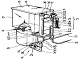
제1도는 전체 의관 사시도.1 is a perspective view of the entire crown.
제2도는 설치함을 제거한 상태 사시도.2 is a perspective view of the installation state removed.
제3도는 일부 절개 정면도.3 is a partial incision front view.
제4도는 일부 절개 측면도.4 is a partial incision side view.
제5도는 여과조와 저수조 및 유출밸브의 연결상태 확대 단면도.5 is an enlarged cross-sectional view of the connection state of the filtration tank, the reservoir and the outlet valve.
제6도는 여과재적치거의 사시도.6 is a perspective view of filter media removal.
제7도는 면적식 유량계의 측단면도.7 is a side cross-sectional view of an area flow meter.
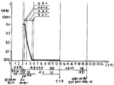
제8도는 24ℓ/일 여과시 잔류염소 농도와 시간선도.FIG. 8 shows the residual chlorine concentration and timeline for 24 l / day filtration.
* 도면의 주요부분에 대한 부호의 설명* Explanation of symbols for main parts of the drawings
1 : 설치함(設置函) 5 : 여과조(濾過槽)1: Installation box 5: Filtration tank
7 : 여과(濾過) 자갈 8 : 여과사(濾過砂)7
9 : 집수구(集水區) 10 : 침전구(沈澱區)9: catchment hole 10: settling hole
11 : 여과재적치거(濾過材積置渠) 15 : 저수조(貯水漕)11: filter stock removal 15: water tank
17 : 통기공(通氣孔) 18 : 유출밸브(流出밸브)17: ventilation hole 18: outflow valve
19 : 유입유출관부(流入流出管部) 20 : 여과수유입관부(濾過水流入管部)19: inflow outflow pipe part 20: filtrate inflow pipe part
21 : 도수배관(導水配管) 23 : 제1도수관(第l導水管)21: Drainage pipe 23: 1st water pipe
24 : 면적식유량계(面積式流量計) 27 : 제2도수관(第2導水管)24: area type flow meter 27: second tap water pipe
28 : 도수연결T관(導水連結T管) 30 : 낙적관(落滴管)28: Drainage connection T pipe 30: Droplet pipe
31 : 유입배관(流入配管)31: inlet pipe
32 : 유입 및 수위표시 투명관(流入 및 水位表示透明管)32: transparent tube for inflow and water level indication
33 : 유입도관(流入導管) 34 : 유입연결T란(流入連結T管)33: Inflow conduit 34: Inflow connection T column
37 : 여과조 유입관(激過槽流人管) 38 : 통기 및 소독공(通氣 및 消毒孔)37: filtration tank inlet pipe 38: Aeration and disinfection
41 : 저수조일류관(貯水槽溢流管) 43 : 일류연결T관(溢流連結T管)41: reservoir tank upstream pipe 43: first-class connection T pipe
44 : 배수본관(排水本管) 45 : 역세척(逆洗滌)밸브44: drainage main pipe 45: backwash valve
47 : 배수연결T관(排水連結T管) 48 : 역세척배수관(逆洗條排水管)47: drainage connection T pipe 48: backwash drainage pipe
49 : 도수일류연결관(導水溢流連結管) 50 : 취수(取水)밸브49: first-class connecting pipe 50: water intake valve
51 : 배관함(配管函) 52 : 수위(水位)눈금51: pipe box 52: water level scale
53 : 투명(透明)커버 59 : 여과조 유출관{濾過槽流出管)53: transparent cover 59: filtration tank outflow pipe
61 : 급수관(給水管)61: water supply pipe
본 발명은 일차로 정수처리되어 급수되는 공공상수도의 수도물을 음용에 적합하게 다시 정수처리하는 방법 및 그 장치에 관한 것이다.The present invention relates to a method and an apparatus for firstly purifying tap water of a public water supply, which is firstly purified and supplied with water, suitable for drinking.
일반적으로 공공상수도의 정수처리는 그 정수처리방법의 종류나 그 시설규모의 대소에 불구하고 최종처리는 반드시 염소로서 확실하게 소독하며, 급수전(수도꼭지)에서 수도물이 나올때는 반드시 유리잔류염소로서 0.2ppm 이상 또는 결합잔류염소로서는 1.5ppm 이상의 염소를 함유하도록 처리하고 있다.In general, the water treatment of public water supply is surely disinfected as chlorine regardless of the type of water treatment method or the size of the facility, and 0.2ppm as free residual chlorine when tap water comes out from hydrant (faucet). As an abnormal or combined residual chlorine, it is processed to contain 1.5 ppm or more of chlorine.
그런데 이러한 잔류염소는 위생상 안전을 유지할 수 있으나 음용시 불쾌한 냄새의 원인이 된다.By the way, such residual chlorine can maintain hygiene safety, but cause unpleasant odor when drinking.
따라서 음용하기 전까지는 수도물에 잔류하는 염소는 반드시 필요한 존재이지만 음용할 때에는 이를 제거하는 것이 이상적이다.Therefore, chlorine remaining in the tap water is necessary until drinking, but it is ideal to remove it when drinking.
또한 수도물에 함유되어 있는 유기물질은 세균의 증식조건을 만들어 주기 때문에 이들의 제거도 요구된다.In addition, organic substances contained in tap water create conditions for bacterial growth, so they need to be removed.
그리하여 종래에는 이러한 잔류염소와 미량의 유기물질을 제거하기 위한 많은 종류의 정수기가 개발되어 사용되고 있다.Thus, many kinds of water purifiers have been developed and used to remove such residual chlorine and trace organic substances.
종래의 정수기들은 형식은 다소 다르지만 정수기내에 흡착력이 강한 활성탄소를 넣어 수도물을 이활성탄소층에 급속으로 통과시킴으로써 잔류염소와 유기물질등을 흡착하여 제거하는 방법에 의한 것이었다.Conventional water purifiers have a slightly different form, but the active water is strongly absorbed into the water purifier, and the tap water is rapidly passed through the activated carbon layer to remove and remove residual chlorine and organic substances.
그러나 종래의 수도물을 다시 청수처리하는 방법에 있어서는 최초 사용시에는 비교적 우수한 효과가 있으나, 다음과 같이 많은 문제점이 있다.However, in the conventional method of fresh water treatment again, the first use has a relatively good effect, but there are many problems as follows.
첫째, 세균이 증식하는 문제점이 있다.First, there is a problem that bacteria grow.
세균의 증식은 종래의 수도물을 다시 정수처리하는 방법에 있어 가장 중대한 문제점으로 대두되고 있다. 원래 수도물에는 생활력이 있는 세균이 거의 없는 상태인데 종래의 재 정수처리 방법으로 수도물을 처리하면 그 여과수에서는 수도법상 수질기준이 정하는 일반세균이 허용치의 수 10배 내지 수 1,000배가 검출된다.Bacterial proliferation has emerged as one of the most significant problems in the conventional method of purifying tap water again. Originally, tap water has almost no viable bacteria, but when the tap water is treated by the conventional re-purification method, the general bacteria determined by the water quality standards in the filtered water are detected from 10 to 1,000 times the allowable value.
이처럼 여과수에서 많은 세균이 검출되는 원인은 수시 여과방법으로 구성되어 있기 때문이다.The reason why many bacteria are detected in the filtered water is because it is composed of filtration at any time.
즉, 기존 정수기는 유입밸브(급수전 직결된 경우에는 급수전)를 열면 수도물이 정수기내에 있는 활성탄소층을 급속으로 통과하면서 정수되고, 정수된 여과수를 용기에 받은 후에는 유입밸브를 잠구어 두며 다시 필요할때 같은 방법으로 여과하는 수시 여과방법이기 때문이다.In other words, the existing water purifier is purified by opening the inlet valve (in the case of a water supply, if it is directly connected to the water supply), and the tap water rapidly passes through the activated carbon layer in the water purifier. This is because the filtration method is performed at any time in the same way.
이러한 수시 여과방법에 있어서 유입밸브를 잠그어 두었을때에는 활성탄소층의 체류수(고여있는 물)는 잔류염소의 전부가 활성탄소에 의하여 흡착되어 살균력을 상실한 상태로 됨과 아울러 활성탄소의 표면에는 유기물질이 흡착되어 있는 상태에서 유출구를 통해 들어오는 공기 때문에 용존산소량이 증가하게 된다.In this occasional filtration method, when the inlet valve is locked, the remaining water (solid water) of the activated carbon layer is desorbed by all of the residual chlorine by the activated carbon and loses sterilizing power. In this adsorbed state, the amount of dissolved oxygen increases due to the air entering through the outlet.
결과적으로 정수기내에는 세균이 생존 및 증식할 수 있는 기본조건 즉, 수분, 유기물질 및 산소를 갖춘환경을 조성하게 되는 것이다.As a result, in the water purifier, the basic conditions for bacteria to survive and multiply, that is, create an environment with water, organic matter and oxygen.
따라서 세균이 정수기내에서 급속도로 증식하며, 유입밸브를 열어 다시 여과할때 중식한 세균이 여과수에 혼합되어 유출된다.Therefore, bacteria grow rapidly in the water purifier, and when the filter is opened again by opening the inlet valve, the bacteria are mixed in the filtered water and flow out.
결국 원래의 수도물에서 보다 수 10배 내지 수 l,000배의 세균이 증식된 물을 음용하게 되는 것이다.Eventually, water from 10 to several thousand times more bacteria than the original tap water will be consumed.
또한 이러한 문제점을 해결하기 위하여 살균력이 있는 은으로 활성탄소를 피복하여 활성탄소층의 체류수에 은을 용출시켜 세균증식을 억제하는 방법에 개발되었으나, 이 또한 세균의 중식을 어느정도 감소하는데 불과하였을 뿐 허용치를 크게 초과하는 것은 마찬가지이었다.In addition, in order to solve this problem, it was developed in a method of inhibiting bacterial growth by eluting silver in the retained water of the activated carbon layer by coating activated carbon with bactericidal silver, but this also only slightly reduced the bacterial growth. The same was true for exceeding the allowable value.
더우기 은이 인체에 미치는 영향을 고려하여 이에 대한 규제 여부가 논의 되고 있다.Moreover, considering the effect of silver on the human body, it is being discussed.
둘째, 정수처리 효능의 지속성이 없다.Second, there is no sustained efficacy of water treatment.
활성탄소는 초기에는 흡착성이 강하지만 수도물의 통과량이 증가하면 횹착력이 급감하여 효능이 크게 저하된다.Activated carbon has strong adsorption at first, but when the passage amount of tap water is increased, the adhesion decreases rapidly and the efficacy is greatly reduced.
그 이유는 수도물중의 미세한 물질과 유기물질이 활성 탄소표면에 부착 및 억류되어 이들물질 때문에 활성탄소표면이 물과 직접적으로 접촉할 수 있는 면적이 축소되어 흡착력이 약화되기 때문이다.The reason is that fine and organic substances in tap water adhere to and detain the activated carbon surface, which reduces the area where the activated carbon surface can directly contact water, thereby weakening the adsorption power.
따라서 잔류염소 및 유기물질의 제거효과는 초기에는 비교적 우수하나 약 1개월후부터는 급감하게 되며, 탁질의 제거는 초기부터 불완전하다.Therefore, the removal effect of residual chlorine and organic materials is relatively good at the beginning, but decreases rapidly after about one month, and the removal of turbidity is incomplete from the beginning.
셋째, 균등하게 여과되지 않는다.Third, it is not evenly filtered.
여과방식이 수시여과이며 더우기 여과속도가 초급속으로 되기 때문에 균등하게 여과되지 않는다.Filtration is on-demand and moreover, the filtration rate is super fast, so it is not evenly filtered.
넷째, 여과재의 세척 및 소독이 불가능하다.Fourth, cleaning and disinfection of the filter medium is impossible.
종래의 여과방법에 있어서는 여과재의 세척이나 소독에 대하여는 전혀 고려되지 않았다.In the conventional filtration method, no cleaning or disinfection of the filter medium has been considered.
따라서 세균등으로 오염된 여과수를 음용하게 되는 문제점이 있었다.Therefore, there was a problem of drinking the filtered water contaminated with bacteria.
다섯째, 여과재 또는 정수기 전체의 교체시한이 짧다.Fifth, the replacement time of the entire filter medium or water purifier is short.
즉, 상술한 바와같이 정수처리 효능의 지속성이 없고 세균이 중식되머 세척 및 소독이 불가능하므로 여과재 또는 정수기 전체의 사용수명이 짧아서 자주 교체하여야 한다.That is, as described above, since there is no sustainability of water treatment efficacy and bacteria are eaten, washing and disinfection are impossible, so the service life of the filter medium or the whole water purifier is short and should be replaced frequently.
따라서 본발명은 전기한 제 문제점을 해결함을 목적으로 하는 것이다.Accordingly, the present invention aims at solving the foregoing problems.
즉, 본발명의 목적은 세균의 부활 및 중식을 확실하게 방지하여 항상 청정한 여과수를 얻을수 있도록 하려는 것이다.That is, the purpose of the present invention is to reliably prevent the revival and lunch of the bacteria to always obtain a clean filtered water.
본발명의 다른 목적은 그 정수처리 효능을 지속적으로 유지할 수 있도록 하려는 것이다.Another object of the present invention is to be able to maintain its water treatment efficacy continuously.
본발명의 또 다른 목적은 항상 균등한 상태로 정수처리할수 있도록 하려는 것이다.Another object of the present invention is to ensure that the water treatment is always uniform.
본발명의 또 다른 목적은 여과재를 세척함으로서 늘 청결을 유지할수 있도록 하려는 것이다.Another object of the present invention is to clean the filter medium so that it can always be kept clean.
본발명의 다른 목적은 여과재를 거의 반영구적으로 사용할수 있도록 하려는 것이다.Another object of the present invention is to make the filter medium nearly semi-permanent.
본발명의 수단을 설명하기에 앞서 본발명과 종래방법의 기본적인 차이를 비교하여 약술한다.Before explaining the means of the present invention, the basic differences between the present invention and the conventional method will be outlined.
(가) 여과방식에 있어서 종래방식은 수시여과인데 비하여 본발명은 지속적인 균등한 여과이다.(A) In the filtration method, the conventional method is continuous filtration, whereas the present invention is continuous and uniform filtration.
(나) 여과속도에 있어서 종래에는 초급속 여과(즉 수초 내지 수분이내)인데 비하여 본발명에서는 완속여과이다.(B) In filtration rate, it is a slow filtration in the present invention, compared to conventional filtration (i.e. within a few seconds to a few minutes).
(다) 여과재에 있어서 종래에는 흡착력이 강한 활성탄소인데 비하여 본발명에서는 내구성이 강한 자갈과 모래이다.(C) In the present invention, activated carbon having strong adsorptive power is gravel and sand with high durability in the present invention.
(라) 여과원리에 있어서 종래에는 순간 흡착과 억류인데 비하여 본발명에서는 산화와 억류이다.(D) In the filtration principle, the adsorption and detention are conventionally performed, whereas in the present invention, oxidation and detention are carried out.
(마) 주요구성에 있어서 종래에는 취수, 도수 및 여과인데 비하여 본발명은 취소, 도수, 여과, 저수 및 부대장치로 구성된다.(E) In the main configuration, the present invention is composed of cancellation, distillation, filtration, water storage, and auxiliary devices, compared to conventional water intake, distillation and filtration.
(바) 여과재등의 세척수단에 대하여 종래에는 전연 고려하지 않았는데 비하여 본발명에서는 필요할때 세척할수 있도록 한다.(F) In the present invention, washing means such as filter media have not been considered in the past.
(사) 소독수단에 대하여 종래에는 전연 고려하고 있지 않는데 비하여 본발명에서는 필요에 따라 소독할 수있다.(G) While disinfection means have not been considered in the past, the present invention can disinfect as needed.
(아) 효능의 지속성에 대하여 종래 방법에서는 초기에는 비교적 우수하나 사용에 따라 급감하는데 비하여 본발명에서는 지속적으로 우수하다.(H) Sustainability of Efficacy The conventional method is relatively superior in the early stage, but it is continuously superior in the present invention as compared with the rapid decrease in use.
(자) 여과재 교체에 대하여 종래에는 수시로 교체하여야 하는데 비하여 본발명에서는 반영구적으로 사용한다.(I) Replacement of filter media has to be replaced frequently from time to time, but is used semi-permanently in the present invention.
(차) 효과에 있어서 종래 방법은 잔류염소, 탁질 및 유기물질의 제거가 초기에는 비교적 우수하나 사용함에 따라 효능이 급감하여 일반세균이 허용치의 수 10배 내지 수 1,000배가 검출되는데 비하여 본발명은 지속적으로 일반세균이 거의 없거나 허용치 이내로 되고 잔류염소와 탁질을 거의 완전하게 제거하며 유기물질등을 크게 감소시키고 대장균군이 전연 없다.(C) In the conventional method, the removal of residual chlorine, turbidity, and organic substances is relatively excellent in the early stage, but the efficacy decreases rapidly with the use of general bacteria. It has little or no general bacteria and is within acceptable levels. It completely removes residual chlorine and turbidity, greatly reduces organic matters, and has no E. coli group.
(카) 그외에 본발명에서는 수도물이 세균부활현상이 일어나기 시작하는 시간이내에서 취수, 도수, 유입, 여과 및 저수하여 사용할 수 있는 최소취수량 이상으로 취수하며 이를 위한 수단이 구비된다.(K) In addition, in the present invention, the tap water is withdrawn over the minimum water intake that can be used for intake, distillation, inflow, filtration and storage within the time when bacterial regeneration occurs.
본발명에 의한 수도물을 다시 정수처리하는 방법은 공공상수도의 급수관에 연결한 취수밸브로부터 급수관압에 의하여 수도물을 지속적으로 거의 균등하게 취수하여 수직으로 세워지고 상단 윗면에 통기 및 소독공이 있는 유입 및 수위표시 투명관을 보유하는 유입배관의 상부측면에 면적식 유량계를 보유하는 도수배관을 통하여 도수하여 전기 유입 및 수위표시 투명관내에서 수직낙하 유입하면서 자유수면을 이루게 하고, 밑으로부터 침전구, 여과자갈과 여과사 및 집수구로 구성되는 여과조의 침전구내로 전기 유입배관을 통해 유입되게 하여 상향류 완속여과하며, 그 여과수를 전기 여과조 상부에 설치한 저수조에 저수하면서 저수조의 유출밸브로 유출하여 사용하고, 전기 유입배관의 하부에 연결한 역세척밸브를 열어 저수조의 여과수를 여과조에 역류시켜 여과조를 역세척하며, 저수조일류관에서 일류되는 저수조의 만수위 이상의 여과수와 도수배관의 도수일류연결관에서 일류되는 일정수위 이상의 도수량 및 전기 역세척퇴수를 수직으로 세워진 하나의 배수본관을 통하여 배수구로 배수하고, 필요에 따라 전기 유입배관의 통기 및 소독공을 통해 소독액을 주입하여 유입배관 여과조 및 저수조를 소독하며, 취수밸브로 부터 취수한때부터 저수조의 만수위까지 도달하는 시간은 세균부활현상이 일어나기 시작하는 시간이내가 될수있는 취수량 또는 그 이상으로 취수하는 것을 특징으로 하는 것이다.Water treatment according to the present invention is a method of re-purifying tap water from the intake valve connected to the water supply pipe of the public water supply continuously by taking water supply pressure almost equally by the water supply pressure, standing vertically and the inflow and water level with aeration and sanitizer on the upper surface Water flows through the water pipe with an area-type flow meter on the upper side of the inflow pipe having the display transparent tube to form a free water surface with vertical inflow in the inflow and water level display transparent tube. It flows slowly through the electric inlet pipe into the sedimentation port of the filtration tank consisting of the filter sand and the catchment port, and slows up-flow filtering. Open the backwash valve connected to the lower part of the inlet pipe to filter the water in the reservoir Backwash the filtration tank by backflowing into the tank, and establish one drain main pipe vertically with the water flow rate above the water level above the water tank that is first-classed in the reservoir tank pipe, and above the water level above the water level first-class connection pipe of the water pipe and the electric backwash withdrawal. Disinfect the inlet pipe filtration tank and the reservoir by injecting disinfectant through the aeration and disinfection of the electric inlet pipe if necessary, and the time from the intake pipe to the full water level of the reservoir is bacterial regeneration. It is characterized in that the withdrawal to or above the amount of intake that can be within the time that this starts to occur.
또한 본발명의 방법에 있어서, 전기 취수량은 전기 면적식 유량계의 원하는 취수량의 유량눈금에 부자가 위치하도록 취수밸브로 조절하여 취수함을 특징으로 하는 것이다.In the method of the present invention, the water withdrawal is characterized in that the water intake is controlled by a water intake valve so that the rich is located at the flow rate of the desired water intake of the electric area type flow meter.
또한 본발명의 방법에 있어서, 전기 저수조와 유입배관중 유입 및 수위표시 투명관을 투명체로하여 손실수두에 의한 서로의 수위차를 볼수 있게 하며, 일정이상의 수위차가 되었을때를 전기 역세척 시점으로 하는것을 특징으로 하는 것이다.In addition, in the method of the present invention, it is possible to see the water level difference due to the loss head by using the transparent water inlet and the water level indicator transparent tube in the electric water tank and the inflow pipe, and when the water level difference exceeds a certain level, It is characterized by.
이러한 본발명의 방법을 구현하는데 적합한 수도물을 다시 정수처리하는 장치는 일측에는 전면이 개폐문(3)으로 개폐되는 여과조 설치공간(2)을, 타측에는 전면과 상면이 개방된 배관함 삽입공간(4)을 보유하는 설치항(1)의 여과조 설치공간(2)에는, 여과자갈(7)과 여과사(8)를 상하에 각각 집수구(9)와 침전구(10)가 형성되게 장입하고 여과조 뚜껑(6)을 닫은 여과조(5)를 설치하며, 여과조 설치공간(2)의 상부를 복재한 저수조안치대(l4) 위에 저수조 뚜껑(16)에 통기공(17)이 있는 저수조(15)를 안치하여 유출밸브(18)에 서로 연통되게 형성된 여과수유입관부(20)와 유입유출관부(19)로써 여과조(5)의 상부와 저수조(15)의 하부를 연통연결하고 여과조(5)의 하부에는 상단높이가 저수조(15)와 동일한 유입 및 수위표시 투명관(32)을 보유하는 유입배관(3l)을 연결하며, 공공상수도 급수관(61)에 설치된 취수밸브(50)에 연결되어 면적식 유량계(24)가 설치되고 최후단의 낙적관(30)을 유입 및 수위표시관(32)의 상부측면에 관통 고정한 도수배관(21)을 설치하고, 유입배관(31)과 도수배관(21) 중 유입 및 수위표시 투명관(32)과 면적식 유량계(24)외의 배관은 배관함삽입공간(4)에 삽입되는 배관함(51)내에 설치하고 면적식 유량계(24)는 배관함(51)의 측면에 부착하며, 유입 및 수위표시 투명관(32)은 상단윗면에 통기 및 소독공(38)을 천공하여 배관함(51)의 전면에 설치하고,저수조(15)의 상부측면에는 저수조일류관(41)을 관통설치하여 배수본관(44)에 연결하며, 도수배관(21)의 최상단과 배수본관(44)을 도수일류연결관(49)으로 연결하고, 유입배관(31)의 하부와 배수본관(44)의 하부를 역세척배수관(48)으로 연졀하여 이에 역세척밸브(45)를 설치하는 것을 특징으로 하는 겻이다.Apparatus for re-processing tap water suitable for implementing the method of the present invention is a filter tank installation space (2), the front and the front is opened and closed by the opening and closing door (3) on one side, the pipe box insertion space (4) is opened on the other side and the upper surface (4). In the filtration tank installation space (2) of the installation port (1) which holds (), the filter gravel (7) and the filtration yarn (8) are charged so that a water collecting port (9) and a precipitation hole (10) are formed above and below, respectively, (6) Install the filtration tank (5) closed, and the reservoir (15) with the vent hole (17) in the reservoir lid (16) is placed on the reservoir support base (4), which overlaps the upper part of the filtration tank installation space (2) The upper portion of the
또한 본발명의 장치에서는 전기 여과조(5)내의 여과자갈(7)과 여과사(8)를, 다수의 통수공(12)이 천공되고 저면에 지지각(13)이 설치된 여과재적치거(1l)상에 적치하여 그 하부에 전기 침전구(10)가 형성되게 함을 특징으로 하는 것이다.In addition, in the apparatus of the present invention, the
또 본발명의 장치에서는 전기 유출밸브(18)는 유입유출관부(19)를 저수조(15)의 전면하부에 관통시키고 내외에 패킹(54)(55)을 대고 유임유출관부(19)의 나사부(56)에 고정너트(57)를 조여서 고정하며, 여과수유입관부(20)는 저수조안치대(14)에 천공된 삽입공(58)을 통해 여과조 설치공간(2)내로 관통시켜 여과조 뚜껑(6)에 관통된 여과조 유출관(59)에 저수조 유입연결관(60)으로 연결함을 특징으로 하는 것이다.In addition, in the device of the present invention, the
또한 본발명의 장치에서는 전기 유입배관(31)은 여과조(5) 하부에 관통된 여과조 유입관(37)에 여과조 유입연결관(36)으로 연결된 유입곡관(35)을 유입 및 수위표시 투명관(32)의 하단의 유입도관(33)에 유입연결T관(34)으로 연결하며, 전기 도수배관(21)은, 취수밸브(50)에 도수호스(22)로 연결되는 제1도수관(23)을 면적식유량계(24)의 유입구(25)에 연결하고 면적식유량계(24)의 유출구(26)에 연결되는 제2도수관(27)을 전기 낙적관(30)에 도수연결관(29)과 도수연결T관(28)으로 연결하며, 전기 저수조일류관(41)을 배수본관(44)의 상부에 저수조 일류연결관(42)과 일류연결T관(43)으로 연결하고, 전기 유입연결T관(34)에 역세척밸브(45)의 유입구를 연결하며 배수본관(44) 하단에 배수호스(46)를 연결하는 배수연결T관(47)과 역세척밸브(45)의 유출구 역세척배수관(48)으로 연결하고 전기 도수연결T관(28)과 일류연결T관(43)을 도수일류연결관(49)으로 연결함을 특징으로 하는 것이다.In addition, in the apparatus of the present invention, the electric inlet pipe 31 is introduced into the inlet curved
또한 본발명의 장치에서는, 전기 배관함(51)의 전면에 유입 및 수의표시 투명판(32)의 수위눈금(52)을 표시하며, 유입 및 수위표시 투명관(32)을 투명커버(53)로 씌우는 것을 특징으로 하는 것이다.In addition, in the apparatus of the present invention, the water level scale 52 of the inflow and outward display
이하에 본발명의 방법 및 장치를 도면에 도시한 일실시예로서 설명한다.Hereinafter, the method and apparatus of the present invention will be described as an embodiment shown in the drawings.
도시한 바와같이 일측에는 전면이 개폐문(3)으로 개폐되는 여과조 설치공간(2)을, 타측에는 전면과 상면이 개방된 배관함 삽입공간(4)을 보유하는 설치함(1)의 여과조 설치공간(2)에는, 여과자갈(7)과 여과사(8)를 상하에 각각 집수구(9)와 침전구(10)가 형성되게 장입하고 여과조 뚜껑(6)을 닫은 여과조(5)를 설치하고, 여과조 설치공간(2)의 상부를 복개한 저수조 안치대(14) 위에 저수조뚜껑(16)에 통기공(17)이 있는 저수조(15)를 안치하며, 유출밸브(18)에 서로 연통되게 형성된 여과수유입관부(20)와 유입유출관부(19)로써 여과조(5)의 집수구(9)와 저수조(15)의 하부를 연통 연결한다.As shown, one side of the filtration tank installation space of the installation tank (1) holding the filtration tank installation space (2), which is opened and closed by the opening and closing door (3) on the other side, and the pipe box insertion space (4) with the front and the upper surface opened on the other side. In (2), the filter gravel (7) and the filter gravel (7) and the filter sand (8) are charged so that the water collecting port (9) and the settling port (10) are formed above and below, respectively, and the filter tank (5) with the filter tank lid (6) closed is provided. Filtrate formed in a
전기 여과조(5)내의 여과자갈(7)과 여과사(8)를, 다수의 통수공(12)이 천공되고 저면에 지지각(13)이 실치된 여과재적치거(11)상에 적치함으로써 그 하부에 전기 침전구(l0)가 형성되도륵 한다.The
전기 유출밸브(18)는, 유입유출관부(19)를 저수조(15)의 전면하부에 관통시키고 내의에 패킹(54)(55)을 대고 유입유출관부(19)의 나사부(56)에 고정너트(57)를 조여서 고정하고 여과수유입관부(20)를 저수조안치대(14)에 천공된 삽입공(58)을 통해 여과조 설치공간(1)내로 관통시켜 여과조 뚜껑(6)에 관통된 여과수 유출관(59)에 저수조 유입연결관(60)으로 연결한다.The
전기 여과조(5)의 침전구(10)에는, 공공상수도의 급수관(61)에 실치되어 유량조절 가능한 취수밸브(50)로부터 수도물을 도수배관(21)과 유입배관(31)을 통하여 지속척으로 균등하게 유입시켜 여과자갈(7)과 여과사(8)을 완속으로 통과하면서 여과토록 한다.In the settling
전기 도수배관(21)은 취수밸브(50)에 도수호스(22)로 연결되는 제1도수관(23)의 상단을 면적식 유량계(24)의 유입구(25)에 연결하고, 면적식 유량계(24)의 유출구(26)에 연결되는 제2도수관(27)의 상단을 도수연결T관(28)과 도수연결관(29)을 통해 선단이 하향절곡된 낙적관(30)에 연결하여서 되며, 전기 유입배관(31)은 여과조(5) 하단측면에 관통된 여과조 유입관(37)에 유입곡관(35)을 여과조 유입연결관(36)으로 연결하고, 전기 도수배관(21)의 낙척관(30)이 상부측면에 관통되는 유입 및 수위표시 투명관(32)의 하단의 유입도관(33)과 전기 유입곡관(35)을 유입연결T관(34)으로 연결하여서 된다.The
전기 유입 및 수위표시 투명관(32)의 상단에는 통기 및 소독공(38)을 천공하여 낙적관(30)에서 수직낙하 유입되는 수도물은 유입 및 수위표시 투명관(32)내에서 자유수면을 이루도록 한다.Aeration and
전기 유입배관(31)과 도수배관(21) 중 유입 및 수위표시 투명관(32)과 면적식 유량계(24)외의 배관은 배관함 삽입공간(4)에 삽입되는 배관함(51)내에 설치하고, 면적식 유량계(24)는 배관함(51)의 측면에 부착하며, 유입 및 수위표시 투명관(32)은 배관함(51)의 전방에 설치한다.Pipes other than the inflow and water level display
전기 저수조(15)의 상부측면에는 저수조일류관(41)을 관통설치하여 저수조일류연결관(42)과 일류연결T관(43)으로 배수본관(44)의 상부에 연결하고, 전기 유입연결T관(34)에 역세척밸브(45)의 유입구를 연결하며 배수본관(44)의 하단에 배수호스(46)를 연결하는 배수연결T관(47)과 역세척밸브(45)의 유출구를 역세척배수관(48)으로 연결하고, 전기 도수연결T관(28)과 일류연결T판(43)을 도수일류연결관(49)으로 연결한다.The upper side of the
전기 배관함(51)의 전면에 유입 및 수위표시 투명관(32)의 수위눈금(52)을 표시하며, 유입 및 수위표시투명관(32)은 투명커버(53)로 씌워서 보호한다.The water level scale 52 of the inflow and water level display
전기 면적식 유량계(24)는 제7도와 같이 유입구(25)와 유출구(26)를 내부에 부자(62)가 있는 유량표시관(63)으로 연결하며, 유입구(25)와 유량표시관(63) 사이의 관로(64)를 유량셋팅콘(65)으로 조절토록한 것을 사용한다.The electric area
도면중 미설명 부호 39는 유입 및 수위표시 투명관(32)의 상단을 배관함(51)에 고정하기 위한 고정고리이고, 40은 동투명관(32)의 하단을 지지하기 위한 지지 통체이며, 66은 면적식 유량계(24)의 유량눈금이고, 67은 투명커버(53)를 지지하기 위한 지지판이며, 68은 급수관(61)에 연결된 급수전이고 ,69는 개폐문(3)의 손잡이이다.In the figure, reference numeral 39 is a fixing ring for fixing the upper end of the inflow and water level display
급수관(61)에 설치된 취수밸브(50)를 개방하면 급수관(61)의 수압에 의하여 수도물이 지속적으로 거의 균등하게 도수호스(22)와 제1도수관(23)을 통해 면적식 유량게(24)의 유입구(25)로 유입된다.When the water intake valve 50 installed in the water supply pipe 61 is opened, the tap water flows through the
면적식 유량계(24)의 유입구(25)를 통해 관로(64)로 유입된 수도물로 인하여 유량표시판(63)내의 부자(62)가 부유하면서 소정위치에서 유량을 표시하게 되며, 이때 유량눈금(66)에 의해 판독한다.Due to the tap water flowing into the
여기서 면적식 유량계(24)의 유량눈금(66)을 관찰하면서 취수밸브(50)를 조정하여 원하는 유량눈금(66)에 부자(62)가 위치하도록 하여 두면 그때의 유량눈금(66)이 곧 원하는 취수량이며, 취수밸브(50)를 다시 조정하지 않는한 이 취수량이 지속적으로 취수된다.Here, while adjusting the water intake valve 50 while observing the
취수량을 적게하면 유속이 늦어지고 따라서 여과속도도 늣어지며, 또한 저수조(15)의 만수위까지 도달하는 것도 늦어지고, 취수량을 많게하면 이와 반대가 된다.The smaller the amount of water intake, the slower the flow rate, and thus the lower the filtration rate, and the slower it is to reach the full water level of the
다시 수도물은 면적식 유량계(24)의 유출구(26)에서 제2도수관(27), 도수연결T관(28) 밋 도수연결관(29)을 통해 낙적관(30)에 이르게 되어 도수배관(21)을 떠나 유입배관(31)의 시단부인 유입 및 수위표시 투명관(32)내로 수직낙하 유입된다.Again, the tap water reaches the
수직낙하 유입함에 있어 수도물 방울이 유입 및 수위표시 투명관(32)내의 수면을 반적(울이튕김)하면서 유입되므로 유입상황을 쉽게 볼 수 있다.In the case of vertical inflow, tap water is introduced while the water droplets are introduced while the water surface is inverted and the water level is reflected in the transparent tube (32).
수도물은 다시 유입 및 수위표시 투명관(32)의 하단에서 유입도관(33), 유입연결T관(34), 유입곡관(35), 여과조 유입연결관(36) 및 여과조 유입관(37)을 통해 여과조(5)의 바닥에 형성된 침전구(10)로 유입된다.Tap water is again in the inlet and water level display
여기서 유입 및 수위표시 투명관(32)의 상단면에 천공한 통기 및 소독공(38)으로부터 외부의 공기가 유입 및 수위표시 투명관(32)내로 유입하여 그 내부의 수면에는 항상 대기압이 작용하는 자유수면을 이루기때문에 여과조(5)내의 물과 유입 및 수위표시 투명관(32)의 물은 다같이 수위가 상승하며, 이에따라 여과조(5)에서 상향류가 가능하게 된다Here, the outside air flows into the inflow and water level display
여과조(5)의 바닥에 형성한 침전구(l0)에 유입한 수도물은 여과재적치거(11)의 통수공(12)을 통하여 여과자갈(7) 및 여과사(8)층을 상향류하면서 여과되고 여과사(8)의 상면과 여과조 뚜껑(6) 사이에 형성된 집수구(9)에 여과수가 집속된다.The tap water flowing into the settling
여기서 침전구(10)의 물의 잔류염소 농도는 취수밸브(50)에서 침전구(10)까지 수도물이 도착하는 시간(체류시간)은 비교적 빨라서 잔류염소가 산화소비되는 겻이 거의 없으므로 급수관(61)에서의 잔류염소 농도와 거의 같은 상태를 지속적으로 유지된다.Here, the residual chlorine concentration of the water in the
그런데 여과자갈(7)과 여과사(8)의 공극을 따라 매우 느린속도로 장시간 흐르는 수도물의 잔류염소는 서서히 수도물에 함유하고 있는 피산화물질인 유기물질, 철, 망간, 암모니아성 질소 및 유기성 질소에 의하여 산화소비되면서 그 농도는 점차적으로 감소하게 된다.However, residual chlorine of tap water flowing at a very slow speed for a long time along the pores of the
여과조(5)내의 수도물은 침전구(10)로부터 집수구(9)를 향하여 흐르며, 이에따라 잔류염소 농도는 침전구(10)로부터 집수구(9)까지 점차적으로 감소되는 분포상태가 지속적으로 유지된다.Tap water in the filtration tank (5) flows from the settling port (10) toward the catchment (9), thereby maintaining a distribution state where the residual chlorine concentration gradually decreases from the settling port (10) to the catchment (9).
여과조(5)에 유입된 수도물중의 잔류염소는 이와같은 방법으로 제거되고, 유기물질, 철, 망간, 암모니아성 질소 및 유기성 질소등은 잔류염소의 피산화물질이기 때문에 앞서 설명한 잔류염소에 의하여 산화제거되어 감소된다.Residual chlorine in the tap water flowing into the
수도물중의 탁질은 침전구(10)에서 침전도 되고 매우 느린 속도로 장시간 여과조(5)내의 여과사(8)의 공극사이를 흐르는 동안 부착 및 억류되어 거의 완전하게 제거된다.The turbidity in the tap water may be precipitated at the settling
잔류염소둥의 제거율은 여과조(5)의 용량과 여과속도에 따라 다르다.The removal rate of residual chlorine depends on the capacity of the
즉, 여과조(5)의 용량을 크게하고 여과속도를 느리게 할수록 제거율은 높아지고, 여과조(5)의 용량을 작게 하고 여과속도를 빠르게 할수록 제거율은 낮아진다.In other words, the larger the capacity of the
따라서 여과조(5)의 용량과 여과속도를 조정함으로써 여과조(5)에서 잔류염소를 100% 제거하지 아니하고 집수구(9)의 여과수중에는 매우 미량의 잔류염소를 유지할수 있다.Therefore, by adjusting the capacity and filtration rate of the
여과조(5)에서의 여과수는 집수구(9), 여과조 유출관(59) 저수조 유입연결관(60), 유출밸브(18)의 여과수유입관부(20) 및 유입유출관부(19)를 통해 저수조(l5)내로 지속적으로 유입되며, 유입 및 수위표시 투명관(32)의 수위와 저수조(15)의 수위는 여과자갈(7)과 여과사(8)둥을 통과할때의 손실 수두만큼의 수위차이를 이루며 상승되고, 저수된 여과수는 유출밸브(18)로 유출하여 사용한다.The filtered water in the filtration tank (5) is connected to the water tank (9), the filtration tank outlet pipe (59), the reservoir tank inlet connecting pipe (60), the filtration
저수조(15)에는 신선한 여과수가 지속적으로 유입되고, 유입되는 여과수에는 극히 미량의 잔류염소가 함유하고 있는 상태이며, 저수조(15)내의 여과수에는 이미 잔류염소에 의하여 용이하게 산화될수 있는 물질은 기히 여과조(5)에서 산화된 상태이기 때문에 극히 미량의 잔류염소만 함유되어 있음에도 장시간 저수조(15)에서 유지할수 있고, 만수위에 도달하였는데도 여과수를 사용하지 않은 때는 저수조일류관(41)을 통하여 일류하고 저수조일류연결관(42)와 일류연결T관(43)을 통해 배수본관(44)로 배수할수 있기 때문에 여과수를 신선하게 유지할수 있다.Fresh filtrate is continuously introduced into the
수도물은 공공상수도에서 염소소독후 20시간 이상 경과한후부터 세균부활현상이 일어나기 시작하는 것이 상수도 공학의 정설이다.Tap water is the orthodoxy of water supply engineering that bacterial regeneration occurs after more than 20 hours after chlorine disinfection in public water.
따라서 본발명은 염소소독을 하는 공공상수도의 정수지나 배수지로부터 수도물이 취수밸브(50)까지 도착하는 시간과 안전을 위한 여유시간을 20시간에서 제한 나머지 시간이내에서 수도물을 다시 정수처리하는 것이다.Therefore, the present invention is to purify the tap water again within the remaining time limit to 20 hours from the time the tap water arrives to the water intake valve 50 and the safety time from the water purification or drainage of the public water supply for chlorine disinfection.
즉 취수밸브(50)로 취수한때부터 저수조(15)의 만수위까지 도달하는 시간을 세균부활현상이 일어나기 시작하는 시간이내가 될수 있는 취수량 또는 그 이상의 취수량을 지속적으로 취수하고 이러한 취수량은 기히 앞에서 설명한 바와같이 취수밸브(50)와 면적식 유량계(24)로 조정이 가능하다.That is, withdrawal amount that can be within the time when bacterial revival phenomenon occurs within the time from the water intake valve 50 to the high water level of the
일반적으로 공공상수도에서 염소소독을 하는 정수지나 배수지로 부터 위치에 따라 다소의 차는 있지만 급수전(68)까지 모두 수시간이내에 도착할수 있도록 공공배수관망이 구성되어 있다.In general, although there are some differences depending on the location from the purified water or the drainage station for chlorine disinfection in the public water supply system, the public drainage pipe network is constructed so that the water supply 68 can be reached within a few hours.
또한 본발명은 여과용량에 관계없이 제8도에서 보는 바와같이 10시간이내에서 상기 취수, 도수, 여과 및 저수가 가능하기 때문에 세균부활현상이 일어나기 시작하는 시간이내에서 충분한 여유시간을 갖고 처리할 수 있다.In addition, the present invention can be treated with sufficient spare time within the time when bacterial regeneration occurs because the intake, distillation, filtration and water storage are possible within 10 hours as shown in FIG. have.
이에 관하여는 후술할 실험예에서 보충설명하는 것을 참고하기 바란다.For this, please refer to the supplementary description in the experimental example to be described later.
이리하여 여과조(5)와 저수조(15)는 세균부활현상이 일어나기 시작하는 시간이내의 물이 농도가 점차적으로 감수된 상태의 잔류염소가 지속적으로 유지하고 있기 때문에 세균의 부활이나 증식이 없는 겻이다.Thus, the
이것이 기존방법과 근본적인 차가 있는 점이다.This is a fundamental difference from the existing method.
또한 본발명의 방법으로 수도물을 다시 정수처리한 여과수를 저수조(15)가 만수일때 채수하여 상온에서 24시간 두었다가 세균학적 시험을 수 10번 하었더니 표5에서 보는 바와같이 일반세균의 증식이 별로 없을뿐 아니라, 대장균은 언제나 영이었다.In addition, the filtered water from which the tap water was purified again by the method of the present invention was taken when the
이것은 수도물중의 미량의 유기물질과 생활력이 없는 가사 상태의 세균이 여과조(5)에서 제거되었기 때문이라고 추리된다.It is inferred that this is because a small amount of organic matter in tap water and bacteria in a household state without vitality have been removed from the
즉, 본발명의 방법으로 수도물을 다시 정수처리한 여과수는 수도물보다 더 많은 시간이 경과하여야 세균부활현상이 일어난다는 것을 알수 있는 것이다.In other words, the filtered water after the tap water is purified again by the method of the present invention can be seen that the bacteria regeneration occurs only after more time passes.
따라서 본발명의 방법은 급수 구역내의 어떠한 위치에서도 충분한 여유시간을 갖고 세균부활현상이 일어나기 시작하는 시간이내에서 처리할수 있다.Therefore, the method of the present invention can be processed within a time at which the bacterial revival phenomenon starts to occur with sufficient time at any position in the water supply area.
공공상수도의 급수가 일시중단되었다가 다시 급수를 하기 시작할때나, 이사 및 기타 사정으로 취수밸브(50)를 잠그었다가 여과를 개재할때에는 세균에 대한 안전을 위하여 저수조(15)내의 잔류염소가 1ppm 이상이 될수 있는 농도의 표백분 소독액을 유입 및 수위표시 투명관(32) 상면의 통기 및 소독공(38)에 깔대기를 세우고 주입하면 낙적관(30)으로부터 낙하유입되는 수도물과 유입 및 수위표시 투명관(32) 안에서 혼합되면서 유입도관(33), 유입연결T관(34), 유입곡관(35), 여과조유임연결관(36), 여과조 유입관(37), 여과조(5)의 침전구(10), 여과재적치거(11), 여과자갈(7), 여과사(8), 여과조(5), 저수구(9), 여과조 유출관(59), 저수조유입연결관(60), 유출밸브(18)의 여과수유입관부(20), 유입유출관부(19) 및 저수조(15)내를 확실하게 소독할 수 있으며, 이때 만수된 물은 유출밸브(18)로 유출하여 버리고 다음부터 저수하는 여과수를 사용한다.When the water supply to the public water supply is suspended and the water supply starts again, or when the water intake valve 50 is shut off due to moving or other circumstances and the filtration is interposed, residual chlorine in the
이와같이 본발명에서는 어떠한 경우에도 세균에 대하여 안전하도록 배려되어 있다.In this way, the present invention is considered to be safe against bacteria in any case.
한편 여과를 장기간 계속하면 수도물중의 미세한 탁질등이 침전구(10)에 침전도 되고 여과자갈(7), 여과사(8)에 억류된다.On the other hand, if the filtration is continued for a long time, fine turbidity in tap water may be precipitated in the settling
이것이 점차 누적되면 손실수두도 증가한다.If this builds up gradually, the head of loss also increases.
이러한 현상은 유입 및 수의표시 투명관(32)의 수의와 저수조(15)의 수위차로 알수 있으며, 유입 및 수위표시 투명관(32)과 저수조(15)를 모두 투명체로 하였을때 육안으로 판독할 수 있다.This phenomenon can be seen by the difference between the veterinary inflow and veterinary display
이 수위차가 크게 벌어지면 저수조(15)의 여과수가 만수위에 도달하기 전에 유입 및 수위표시 투명관(32)의 수위가 높아져서 도수량의 일부는 도수일류연결관(49)를 통하여 일류되여 배수본관(44)을 통하여 배수됨으로 통기 및 소독공(38)에서 일류할 염려는 없다.If the water level difference widens, the inlet and the water level indicator
그러므로 이 수위차(손실수두)가 일정이상으로 벌어지면 여과조(5)에 억류되어 있는 탁질을 여과조(5) 밖으로 배출할 필요가 있다.Therefore, if this water level difference (loss head) spreads beyond a certain level, it is necessary to discharge the suspended matter held in the
저수조(15)의 수위가 만수위에 달하였을때 역세척밸브(45)를 개방하면 저수조(15)의 여과수가 유출밸브(18)의 유입유출관부(19) 및 여과수유입관부(20), 저수조유입연결관(60), 여과조 유출관(59), 집수구(9), 여과사(8), 여과자갈(7), 여과재적치거(11)의 통수공(12), 침전구(10), 여과조 유입관(37), 여과조유입연결관(36), 유입곡관(35), 유입연결T관(34), 역세척밸브(45), 역세척배수관(48), 배수연결T관(47) 및 배수호스(46)를 통하여 역세척퇴수가 배수되어 배수구로 배출된다.When the water level of the
이때 여과자갈(7)과 여과사(8)에 억류되어 있는 탁질과 침전구(10)의 침전물이 급속으로 역류하는 유속에 의하여 배출되는 겻이다.At this time, the sediment of the turbidity and
저수조(15)의 수위가 저수위(유출밸브(18)의 유입유출관부(19)의 위치의 수위)에 달하면 역세척을 마치기 위하여 역세척밸브(45)를 잠그어 여과조(5)내에는 외부의 공기가 직접적으로 유입할수 없게 한다.When the water level of the
이것은 공기로 인한 여과조(5)내의 세균증식을 방지하기 위함이다.This is to prevent bacterial growth in the
저수조(15)의 수위가 만수가 될때까지도 여과수를 사용하지 않을때는 저수조(15)내의 여과수는 저수조일류관(41), 저수조일류연결관(42), 일류연결T관(43), 배수본관(44) 및 배수연결T관(47)을 통하여 배수호스(46)로 배수된다.When the filtrate is not used even when the water level of the
취수밸브(50)를 처음 열때 잘못열어 초과 도수가 있을때는 초과도수량의 일부는 도수일류연결관(49), 배수본관(44) 및 배수호스(46)를 통해 배수구로 배수된다.When the water intake valve 50 is initially opened and there is excess water, a part of the excess water is drained to the drain through the first-
전기 유입배관(31)의 유입 및 수위표시 투명관(32)을 투명으로 하여 그 상부측에 관통되어 그 선단이 유입 및 수위표시 투명관(32)의 중심선상에서 하향절곡되어 개구된 낙척관(30)으로 부터 수도물이 수직하방으로 낙하하여 유입 및 수위표시 투명관(32)내로 유입되며, 유입 및 수위표시 투명관(32)내의 수면에서 항시 반적하기 매문에 육안으로 유입현황을 식별할수 있어 도수량(즉 여과수 생산량)을 변경하고 싶으면 면적식유량계(24)를 보면서 취수밸브(50)를 조정하면 된다.Falling
또 만일 저수조(15)를 불투명체로 하였을 경우에는 유입 및 수위표시 투명관(32)의 수위와 배관함(51)의 전면에 있는 수위눈금(52)으로써 저수조(15)의 저수량을 알수 있다.In addition, if the
유입 및 수위표시 투명관(32)과 저수조(16)를 모두 투명체로 하였을 경우에는 상호간의 수위차(손실수두)로써 여과조(5)의 세척시기를 알수 있다.When both the inflow and the water level display
본발명에서는 여과재가 모래(8)와 자갈(7)로서 내구성이 강하고 여과작용이 자갈, 모래 자체의 작용에 의한 것이 아니고 자갈(7), 모래(8)의 공극에서 수도물중의 잔류염소와 피산화물질간의 산화작용으로 여과가 이루어지며, 억류된 탁질은 수시로 전술한 바와같이 역세척하여 외부로 배출할수 있으므로 효능을 변화없이 지속된다.In the present invention, the filter medium is sand (8) and gravel (7), durable and filtration is not caused by the action of gravel, sand itself, but residual chlorine and blood in tap water in the pores of gravel (7), sand (8) Filtration is achieved by oxidizing the oxides, and the suspended solute can be backwashed and discharged to the outside as described above from time to time, thus maintaining its efficacy without change.
또 여과재인 자갈과 모래는 내구성이 강하여 반영구적이며, 따라서 여과재를 교체할 필요가 없다. 결국 본발명의 효능을 그대로 지속할수 있음을 이해할 수 있다.In addition, the filter media gravel and sand is durable and semi-permanent, so there is no need to replace the filter media. It can be understood that the efficacy of the present invention can be sustained as it is.
한편 본발명에 있어 여과조(5)와 저수조(15)의 연결 및 저수조(15)의 여과수 유출을 하나의 유출밸브(18)로써 겸용할 수 있도록 한 것도 하나의 특징이다.On the other hand, in the present invention, the connection between the
이에따라 저수조(15)에는 하나의 구멍으로써 유입 및 유출을 할 수 있어 간편하게 된다.Accordingly, the
다듬 본발명을 실험예로서 설명한다.The present invention will be described as an experimental example.
실험은 다음의 규격과 조건으로 행하였다.The experiment was conducted under the following specifications and conditions.
(가) 규격(A) Standard
여기서는 본발명의 효능에 직접 관계되는 부분만을 실정한 것이다.Here, only the part directly related to the efficacy of the present invention has been identified.
(1) 여과조(1) filtration tank
직경 0.19m0.19m in diameter
높이 0.17m0.17m in height
침전구의 높이 0.02mSettling height 0.02m
여과자갈 높이 0.03mFilter height 0.03m
여과사 높이 0.lmFilter sand height 0.lm
집수구 높이 0.02mCatchment height 0.02 m
여과 자갈의 크기 3-8mm, 공극율 40%Size of filtration gravel 3-8mm, porosity 40%
여과사는 표준완속 여과사로서 공극율 45%Filtration yarn is a standard slow filter yarn with 45% porosity
(2) 저수조(2) reservoir
가로 0.23m0.23m in width
세 로 0.17m0.17m in height
만수위까지의 높이0.18mHeight to the full water level 0.18m
(3) 여과조의 단면적(3) cross-sectional area of filtration tank
즉, 여과면적(a) =0.028㎡That is, the filtration area (a) = 0.028
(4) 용적(4) volume
도수 및 유입배관용적(b)=0.00022㎥Frequency and inflow piping volume (b) = 0.00022㎥
여과조 공극용적(c)=0.0026㎥Filtration tank pore volume (c) = 0.0026㎥
저수조의 만수위까지의 용적(d)=0.007㎥Volume up to full water level of reservoir (d) = 0.007㎥
전용적(b+c+d)=0.00982㎥(e)Dedicated (b + c + d) = 0.00982㎥ (e)
(나) 여과속도와 체류시간은 다음 표1과 같다.(B) Filtration speed and residence time are shown in Table 1 below.
[표 1]TABLE 1
여과속도 및 체류시간Filtration Speed and Retention Time

(다) 수질분석결과는 다음 표2, 표3, 표4, 및 표5와 같다.(C) The water quality analysis results are shown in the following Table 2, Table 3, Table 4, and Table 5.
(표2, 표3 삽입)(Table 2, Table 3 insertion)
[표 2]TABLE 2
수질분석Water quality analysis

[표 3]TABLE 3
수질분석(이호학적 시험 및 제거율)Water quality analysis (physiological tests and removal rates)

[표 4]TABLE 4
수질분석(세균학적 시험)Water quality analysis (bacterial test)

[표 5]TABLE 5
여과수를 채수하여 상온에서 24시간 두었다가 실시한 세균학적 시험Bacteriological test with filtered water and allowed to stand at room temperature for 24 hours

이상에서 실험예를 검토하면 1일 24ℓ여과할 때 표1에서 여과속도는 0.85m/일이고, 여과하는데 소요된 시간(여과조(5)의 체류시간)은 2.6시간이며, 저수조(15)는 7시간분(저수조(15)의 체류시간)의 여과생산량을 저수할 수 있는 용량이고, 취수밸브(50)로부터 저수조(15)의 만수위까지 도달하는데는 9.82시간(전체류시간)이 소요됨을 알수 있다.When the experimental example is reviewed above, the filtration rate is 0.85 m / day when filtering 24 L per day, the time required for filtration (retention time of the filtration tank 5) is 2.6 hours, and the
이렇게 여과할때 표2 및 표3에서 잔류염소는 90% 이상 탁질은 100% 유기물질(BOD)은 약 10% 질산성필소는 3% 이상 증발잔유물은 6% 이상이 제거되고, 이때 일반세균은 언제나 허용치 이내이며, 대장균군은 영임을 알수 있다.When filtration is performed, the residual chlorine in Table 2 and Table 3 is more than 90%, the turbidity is 100%, the organic matter (BOD) is about 10%, the nitrate is more than 3%, and the evaporation residue is more than 6%. It is always within tolerance and E. coli is zero.
여기에서 주목할 것은 0.85m/일의 매우 느린 여과속도로 2.6시간 여과한 여과수에는 저수조(15)가 만수일때까지도 미량의 잔류염소가 지속적으로 남아있다는 사실과 만수위에 도달하는 시간이 세균부활현상이 일어나기 시작하는 시간이내라는 사실이다.It should be noted that in the filtered water filtered for 2.6 hours at a very slow filtration rate of 0.85 m / day, a small amount of residual chlorine remains until the
즉, 이 사실은 세균부활현상이 일어나기 시작하는 시간이내의 물이 취수밸브(50)로부터 저수조(15)의 만수위까지 잔류염소의 농도가 점차적으로 감소된 상태를 지속적으로 유지하고 있어 세균의 부활이나 증식이 있을 수 없다는 것을 이해할 수 있다.In other words, this fact is that the water within the time when the bacterial revival starts to occur, the concentration of residual chlorine continues to gradually decrease from the intake valve 50 to the full water level of the
앞에서 기히 설명한 바와같이 공공상수도에서 염소 소독후 20시간 이상 경과하여야 세균부활현상이 일어나는데, 본 시험의 모형의 경우는 9.82시간(표 1. 전체류시간)이 소요되었으므로 나머지 10.18시간은 공공상수도의 정수지로부터 취수밸브(50)까지 도착하는 시간과 안젼을 고려한 여유시간을 합한 시간이 된다.As mentioned above, bacterial regeneration occurs only 20 hours after chlorine disinfection in the public water supply system. In this model, 9.82 hours (Table 1. Total flow time) was used. Time to arrive from the water intake valve 50 to the safety time in consideration of safety.
동일한 본 모형으로 1일 48ℓ를 여과할때는 표1에서 전체류시간은 4.91시간임을 알수 있다.When filtering 48 liters a day with the same model, the total flow time is 4.91 hours in Table 1.
따라서 본 모형의 용량으로는 1일 24ℓ이상을 여과하면 모두 세균부활현상이 일어나기 시작하는 시간 이내에서 충분한 여유시간을 갖으면서 여과할수 있다는 것을 이해할 수 있을 것이다.Therefore, as the capacity of this model, if you filter more than 24ℓ per day, it can be understood that all of them can be filtered with sufficient time within the time when bacterial regeneration occurs.
즉, 본 모헝 용량의 허용 1일 최소 여과량은 24ℓ/일로 할수 있다.In other words, the minimum allowable daily filtration amount of this polymer capacity can be 24 l / day.
1일 24ℓ를 여과하고자 할때 면적식 유량계(24)의 부자(62)의 위치를 유량눈금(66)의 24ℓ를 가르키는 눈금 위치에 있도록 취수밸브(50)를 조정하여 두면 24ℓ/일의 취수량이 지속적으로 거의 균등하게 취수된다.If you want to filter 24 liters per day, adjust the water intake valve 50 so that the position of the rich 62 of the
표2, 표3, 표4 및 표5에서 동일 모형으로 24ℓ/일을 여과할때나 48ℓ/일을 여과생산할때 여과수의 수질차가 별로 없다는 것도 알수 있다.Table 2, Table 3, Table 4 and Table 5 show that there is not much difference in the water quality when filtering 24ℓ / day or 48ℓ / day with the same model.
이것은 동일 용량의 장치로 수도물을 다시 정수처리하는 량의 범위가 넓다는 것을 이해할 수 있는 것이다.This can be understood that the range of the amount of water to be purified again with a device of the same capacity.
여과시 잔류염소의 농도 상태와 시간과의 관계를 도표로 나타내면 제8도와 같다.Figure 8 shows the relationship between the concentration state of residual chlorine and the time of filtration.
제8도에서 보듯이 표1의 전체류시간은 9.82시간이며, 공공상수도의 정화지에서 취수밸브(50)까지 도달하는 시간을 3시간으로 추정하면 안전을 고려한 여유시간은 7.18시간이 되므로 충분한 여유가 있음을 알수있다.As shown in FIG. 8, the total flow time shown in Table 1 is 9.82 hours, and when the time to reach the intake valve 50 from the clarified place of the public water supply is estimated to be 3 hours, the safety time is 7.18 hours. It can be seen that.
또한 제8도에서 급수관(61)에서의 잔류염소 농도가 0.4ppm일때를 고찰하여 보면 침전구(10)까지는 거의 동일농도로 유지되며, 여과자갈(7)과 여과사(8)를 통과하는 동안 거의 전부 제거되고 집수구(9)에서 저수조(15)의 만수위까지는 수온과 수질에 마라 다소의 차는 있지만 0.015ppm 정도의 잔류염소가 지속적으로 유지된다.In addition, in FIG. 8, when the residual chlorine concentration in the water supply pipe 61 is 0.4 ppm, the concentration is maintained at about the same concentration up to the settling
제8도에서 하루 24ℓ를 여과할때 공공상수도의 정수지나 배수지로부터 취수밸브(50)까지 도착하는데 3시간(추정), 저수조(15)의 만수위까지 도달하는데 9.82시간이 소요되고 이로부터 24시간이내에서는 여과수의 세균부활이나 증식이 별로 없다는 것을 표5에서 알수 있다.In FIG. 8, when filtering 24 liters per day, it takes 3 hours (estimation) to reach the intake valve 50 from the water supply or drainage of the public water supply, and 9.82 hours to reach the full water level of the
이것은 본발명의 방법은 급수구역내의 어떤 위치에서도 충분한 여유시간을 갖고 세균부활현상이 일어나기 시작하는 시간이내에서 가능하다는 것을 이해할 수 있다.It can be understood that the method of the present invention is possible within a time at which the bacterial revival phenomenon begins to occur with sufficient time at any location in the water supply area.
이상 설명한 명세내용을 요약 정리하면 본발명의 여과방식은 지속적인 균등완속여과이며 여과재는 자갈과 모래이고 여과원리는 자갈과 모래 공극에서 잔류염소는 피산화물질을 산화시켜 소비되여 제거되고 이에따라 피산화물질도 제거되며 탁질은 자갈 및 모래 공극에 억류되여 제거되고 처리시간은 취수부터 저수조(15) 만수위까지 도달하는데 수도물의 세균부활현상이 일어나기 시작하는 시간이내가 될수 있는 취수량 또는 그 이상으로 취수하며, 공공상수도의 급수가 일시중단 되였다가 다시 급수할때나 사정에 따라 여과를 일시 중지하였다가 재개할때는 소독을 하고 여과조(5)에 억류된 탁질을 필요에 따라 외부로 역세척 배출하는 방법으로 수도물을 다시 정수처리하면 그 효과는 수도물중의 잔류염소, 탁질, 냄새, 유기물질 및 기타 피산화물질을 감소 내지 제거하면서도 일반세균은 허용치 이내이며, 대장균군은 언제나 전무이고 효능은 변화없이 지속되며, 여과재는 반영구적으로 사용할수 있어 교체할 필요가 없는 효과가 있다.In summary, the filtration method of the present invention is continuous uniformly slow filtration, the filter medium is gravel and sand, and the filtration principle is that residual chlorine is consumed by oxidizing the oxidizing substance in the gravel and sand pores. Also, the turbidity is detained in the gravel and sand voids to be removed, and the treatment time reaches the water level from the intake to the
Claims (7)
Priority Applications (9)
| Application Number | Priority Date | Filing Date | Title |
|---|---|---|---|
| KR1019870010141A KR900006437B1 (en) | 1987-09-12 | 1987-09-12 | Water purifying apparatus |
| JP63119048A JPS6475011A (en) | 1987-09-12 | 1988-05-16 | Treatment method and apparatus for repurification of city water |
| US07/239,177 US4946600A (en) | 1987-09-12 | 1988-08-31 | Water repurification method of city water and its equipment |
| CA000576236A CA1321955C (en) | 1987-09-12 | 1988-08-31 | Water repurification method of city water and its equipment |
| AU22009/88A AU625172B2 (en) | 1987-09-12 | 1988-09-08 | Water repurification method of city water and its equipment |
| BR8804698A BR8804698A (en) | 1987-09-12 | 1988-09-12 | PROCESS AND EQUIPMENT FOR REPURIFICATION OF WATER, URBAN WATER OR TAP |
| AR311911A AR240304A1 (en) | 1987-09-12 | 1988-09-12 | WATER REPURIFICATION DEVICE FOR PUBLIC SERVICE AND METHOD FOR ITS REALIZATION WITH THE SAME. |
| GB8821366A GB2209686B (en) | 1987-09-12 | 1988-09-12 | Water repurification method and apparatus |
| US07/507,039 US5110482A (en) | 1987-09-12 | 1990-04-10 | Water repurification method of city water and its equipment |
Applications Claiming Priority (1)
| Application Number | Priority Date | Filing Date | Title |
|---|---|---|---|
| KR1019870010141A KR900006437B1 (en) | 1987-09-12 | 1987-09-12 | Water purifying apparatus |
Publications (2)
| Publication Number | Publication Date |
|---|---|
| KR890004757A KR890004757A (en) | 1989-05-09 |
| KR900006437B1 true KR900006437B1 (en) | 1990-08-31 |
Family
ID=19264447
Family Applications (1)
| Application Number | Title | Priority Date | Filing Date |
|---|---|---|---|
| KR1019870010141A KR900006437B1 (en) | 1987-09-12 | 1987-09-12 | Water purifying apparatus |
Country Status (8)
| Country | Link |
|---|---|
| US (2) | US4946600A (en) |
| JP (1) | JPS6475011A (en) |
| KR (1) | KR900006437B1 (en) |
| AR (1) | AR240304A1 (en) |
| AU (1) | AU625172B2 (en) |
| BR (1) | BR8804698A (en) |
| CA (1) | CA1321955C (en) |
| GB (1) | GB2209686B (en) |
Cited By (1)
| Publication number | Priority date | Publication date | Assignee | Title |
|---|---|---|---|---|
| CN106075990A (en) * | 2016-07-11 | 2016-11-09 | 盐城工学院 | A kind of middle Water Sproading groove for wheat washer |
Families Citing this family (34)
| Publication number | Priority date | Publication date | Assignee | Title |
|---|---|---|---|---|
| KR900006437B1 (en) * | 1987-09-12 | 1990-08-31 | 신경식 | Water purifying apparatus |
| KR950002543B1 (en) * | 1992-05-12 | 1995-03-21 | 정중석 | Water supply apparatus |
| CA2096875C (en) * | 1992-05-27 | 2004-03-16 | Steven M. Peddicord | Water softener salt platform |
| US5288399A (en) * | 1992-08-28 | 1994-02-22 | Schulz Christopher R | Gravity flow filter with backwash control chamber |
| JP2847053B2 (en) * | 1994-11-14 | 1999-01-13 | 三星電子株式会社 | Water purifier overflow prevention device |
| US5788933A (en) | 1995-05-26 | 1998-08-04 | Donald B. Peddicord | Salt platform |
| US5643541A (en) * | 1995-05-02 | 1997-07-01 | Peddicord; Steven M. | Salt platform |
| US5950732A (en) * | 1997-04-02 | 1999-09-14 | Syntroleum Corporation | System and method for hydrate recovery |
| US6183704B1 (en) | 1998-07-14 | 2001-02-06 | Donald B. Peddicord | Salt platform |
| JP4113638B2 (en) * | 1999-06-24 | 2008-07-09 | 芳聰 前田 | Water storage tank and water purifier |
| US6331255B1 (en) | 1999-07-09 | 2001-12-18 | Donald B. Peddicord | Accessible well for brine tank |
| US6391191B2 (en) * | 1999-10-14 | 2002-05-21 | Fantom Technologies Inc. | Domestic water treatment appliance |
| US6589491B1 (en) | 2000-02-18 | 2003-07-08 | Donald B. Peddicord | Salt platform |
| US6814946B1 (en) * | 2000-03-03 | 2004-11-09 | Donald B. Peddicord | Salt platform with hub having locking element |
| US7614508B2 (en) | 2001-08-23 | 2009-11-10 | Pur Water Purification Products Inc. | Water filter materials, water filters and kits containing silver coated particles and processes for using the same |
| US7615152B2 (en) | 2001-08-23 | 2009-11-10 | Pur Water Purification Products, Inc. | Water filter device |
| US7614507B2 (en) | 2001-08-23 | 2009-11-10 | Pur Water Purification Products Inc. | Water filter materials, water filters and kits containing particles coated with cationic polymer and processes for using the same |
| US20050279696A1 (en) | 2001-08-23 | 2005-12-22 | Bahm Jeannine R | Water filter materials and water filters containing a mixture of microporous and mesoporous carbon particles |
| KR100777951B1 (en) | 2001-08-23 | 2007-11-28 | 더 프록터 앤드 갬블 캄파니 | Water filter materials, corresponding water filters and processes for using the same |
| US7087162B2 (en) * | 2001-09-24 | 2006-08-08 | Peddicord Donald B | Accessible well for brine tank |
| KR20020026345A (en) * | 2002-03-22 | 2002-04-09 | 전영철 | Water-supply stand with a water purifier inside |
| GB2412115B (en) * | 2004-02-20 | 2009-08-19 | Leighton Harris James | The invention relates to a stand-alone water filtration, purification and storage unit |
| EP2070574A1 (en) * | 2007-12-14 | 2009-06-17 | Heinrich Sprick | Pressure filter and method for cleaning fluids |
| JP2009297647A (en) * | 2008-06-12 | 2009-12-24 | Yamaha Motor Co Ltd | Slow filtration device, and slow filtration system comprising the same |
| US20090321435A1 (en) * | 2008-06-30 | 2009-12-31 | Max Michael D | Water Handling System |
| US8128820B2 (en) * | 2009-02-25 | 2012-03-06 | Mr. Chiaphua Industries Limited | UV liquid storage and dispensing device |
| KR100989414B1 (en) * | 2010-03-15 | 2010-10-26 | 대송환경개발(주) | Equipment for the treatment of waste liquid using water-purifier tank |
| CN102837261B (en) * | 2012-08-17 | 2014-11-05 | 江苏嘉洋华联建筑装饰有限公司 | Recycling method for cast-in-situ terrazzo floor polishing waste slurry |
| CN102814078B (en) * | 2012-08-17 | 2014-06-11 | 江苏嘉洋华联建筑装饰有限公司 | Cast-in-situ terrazzo grade level polishing waste slurry recovery device |
| JP6276525B2 (en) * | 2013-07-03 | 2018-02-07 | 株式会社竹村製作所 | Water treatment equipment using filtration sand |
| CN104722135B (en) * | 2015-03-16 | 2016-02-24 | 大庆聚三元环保科技开发有限公司 | Tiny flocculation continuous sand filter |
| CN105944448B (en) * | 2016-06-10 | 2019-02-12 | 江苏蓝天水净化工程有限公司 | A kind of full-automatic back washing water purifier |
| US11161062B2 (en) | 2017-04-03 | 2021-11-02 | Wellspringpure, Llc | Filter systems and related methods |
| US10905976B2 (en) * | 2017-04-03 | 2021-02-02 | Wellspringpure, Llc | Filter systems and related methods |
Family Cites Families (20)
| Publication number | Priority date | Publication date | Assignee | Title |
|---|---|---|---|---|
| US537705A (en) * | 1895-04-16 | Filter | ||
| US459099A (en) * | 1891-09-08 | Oil-filter | ||
| US420428A (en) * | 1890-02-04 | Process of filtering oil | ||
| US231480A (en) * | 1880-08-24 | Filter | ||
| US224680A (en) * | 1880-02-17 | Filter | ||
| US524827A (en) * | 1894-08-21 | And clayton test | ||
| US331790A (en) * | 1885-12-08 | Filter | ||
| US826654A (en) * | 1906-04-18 | 1906-07-24 | Franklin E Firth | Self-cooling filter system. |
| US869294A (en) * | 1907-05-02 | 1907-10-29 | Lucius R Clark | Filter. |
| US989965A (en) * | 1910-05-14 | 1911-04-18 | Crystal Mfg And Patent Company | Faucet-filter. |
| US1329462A (en) * | 1918-07-30 | 1920-02-03 | Henry J Frey | Filter |
| US1433357A (en) * | 1920-12-17 | 1922-10-24 | James G Ellis | Filter |
| US3202286A (en) * | 1962-05-14 | 1965-08-24 | Octrooien Mij Activit Nv | Filtering apparatus |
| US3841485A (en) * | 1972-05-08 | 1974-10-15 | Permutit Co Inc | Automatically backwashed gravity filter |
| US4086165A (en) * | 1974-07-25 | 1978-04-25 | Augusto Formenti | Liquid-treatment system |
| US4028241A (en) * | 1975-08-25 | 1977-06-07 | Hungerford & Terry, Inc. | Apparatus for and method of recovering water used to backwash and rinse a filter |
| GB2022437B (en) * | 1978-05-04 | 1982-05-06 | Biwater Shellabear Ltd | Water treatment unit |
| FR2509283B1 (en) * | 1981-07-10 | 1986-09-05 | Foessel Eugene | REGENERATION UNIT FOR WASTEWATER FROM INDUSTRIAL FLUSHING PLANTS |
| US4692246A (en) * | 1986-04-17 | 1987-09-08 | Simon Abraham E | Cartridge filter with plural medias |
| KR900006437B1 (en) * | 1987-09-12 | 1990-08-31 | 신경식 | Water purifying apparatus |
-
1987
- 1987-09-12 KR KR1019870010141A patent/KR900006437B1/en not_active IP Right Cessation
-
1988
- 1988-05-16 JP JP63119048A patent/JPS6475011A/en active Granted
- 1988-08-31 US US07/239,177 patent/US4946600A/en not_active Expired - Lifetime
- 1988-08-31 CA CA000576236A patent/CA1321955C/en not_active Expired - Fee Related
- 1988-09-08 AU AU22009/88A patent/AU625172B2/en not_active Ceased
- 1988-09-12 BR BR8804698A patent/BR8804698A/en not_active IP Right Cessation
- 1988-09-12 AR AR311911A patent/AR240304A1/en active
- 1988-09-12 GB GB8821366A patent/GB2209686B/en not_active Expired - Lifetime
-
1990
- 1990-04-10 US US07/507,039 patent/US5110482A/en not_active Expired - Fee Related
Cited By (1)
| Publication number | Priority date | Publication date | Assignee | Title |
|---|---|---|---|---|
| CN106075990A (en) * | 2016-07-11 | 2016-11-09 | 盐城工学院 | A kind of middle Water Sproading groove for wheat washer |
Also Published As
| Publication number | Publication date |
|---|---|
| KR890004757A (en) | 1989-05-09 |
| GB2209686A (en) | 1989-05-24 |
| US4946600A (en) | 1990-08-07 |
| GB2209686B (en) | 1991-12-11 |
| US5110482A (en) | 1992-05-05 |
| BR8804698A (en) | 1989-04-18 |
| CA1321955C (en) | 1993-09-07 |
| JPS6475011A (en) | 1989-03-20 |
| GB8821366D0 (en) | 1988-10-12 |
| AR240304A1 (en) | 1990-03-30 |
| AU625172B2 (en) | 1992-07-02 |
| JPH0228364B2 (en) | 1990-06-22 |
| AU2200988A (en) | 1989-03-16 |
Similar Documents
| Publication | Publication Date | Title |
|---|---|---|
| KR900006437B1 (en) | Water purifying apparatus | |
| KR100757496B1 (en) | Water tank with clean water treatment apparatus | |
| CN103771644B (en) | Multifunctional water purifier | |
| KR20000013587A (en) | Water purifying system | |
| KR100619094B1 (en) | A waste water disposal plant | |
| IE20090511A1 (en) | An effluent treatment process | |
| JP3773360B2 (en) | Septic tank with membrane separation | |
| JPH10323683A (en) | Water purification treatment and device | |
| KR830007442A (en) | Wastewater Treatment Method and Apparatus | |
| KR20090013556A (en) | High-turbidity filter | |
| JP3714727B2 (en) | Filtration method in sewage treatment | |
| KR20020093663A (en) | Reverse osmosis water purifier | |
| JPS6197095A (en) | Body construction of city water cleaning up device | |
| KR20040023291A (en) | Purified system having electro dialysis | |
| KR101412852B1 (en) | Sediment filter | |
| JPH04284894A (en) | Controlling method of biological treatment of sewage and its apparatus | |
| JP3329664B2 (en) | Septic tank | |
| JPH09206793A (en) | Sewage treatment and sewage treating device | |
| KR200168452Y1 (en) | Reverse osmosis water purifier | |
| JP2003181483A (en) | Method for treating septic tank and the septic tank | |
| JP2003251363A (en) | Reclaimed water feed apparatus | |
| JPH0338289A (en) | Biologically activated carbon water-treatment apparatus | |
| KR0170609B1 (en) | Method for discharging solution preserving membrane filter of an waterpurifier | |
| KR100942132B1 (en) | High-turbidity filter | |
| KR100305361B1 (en) | Household sewage treatment device |
Legal Events
| Date | Code | Title | Description |
|---|---|---|---|
| A201 | Request for examination | ||
| E902 | Notification of reason for refusal | ||
| G160 | Decision to publish patent application | ||
| E701 | Decision to grant or registration of patent right | ||
| GRNT | Written decision to grant | ||
| FPAY | Annual fee payment |
Payment date: 19951226 Year of fee payment: 7 |
|
| LAPS | Lapse due to unpaid annual fee |