KR900005709B1 - Motor-driven power steering apparatus - Google Patents
Motor-driven power steering apparatus Download PDFInfo
- Publication number
- KR900005709B1 KR900005709B1 KR1019860004421A KR860004421A KR900005709B1 KR 900005709 B1 KR900005709 B1 KR 900005709B1 KR 1019860004421 A KR1019860004421 A KR 1019860004421A KR 860004421 A KR860004421 A KR 860004421A KR 900005709 B1 KR900005709 B1 KR 900005709B1
- Authority
- KR
- South Korea
- Prior art keywords
- current
- electric motor
- voltage
- battery
- motor
- Prior art date
Links
Images


Classifications
-
- B—PERFORMING OPERATIONS; TRANSPORTING
- B62—LAND VEHICLES FOR TRAVELLING OTHERWISE THAN ON RAILS
- B62D—MOTOR VEHICLES; TRAILERS
- B62D5/00—Power-assisted or power-driven steering
- B62D5/04—Power-assisted or power-driven steering electrical, e.g. using an electric servo-motor connected to, or forming part of, the steering gear
- B62D5/0457—Power-assisted or power-driven steering electrical, e.g. using an electric servo-motor connected to, or forming part of, the steering gear characterised by control features of the drive means as such
- B62D5/0475—Controlling other elements
- B62D5/0478—Clutches
-
- B—PERFORMING OPERATIONS; TRANSPORTING
- B62—LAND VEHICLES FOR TRAVELLING OTHERWISE THAN ON RAILS
- B62D—MOTOR VEHICLES; TRAILERS
- B62D5/00—Power-assisted or power-driven steering
- B62D5/04—Power-assisted or power-driven steering electrical, e.g. using an electric servo-motor connected to, or forming part of, the steering gear
- B62D5/0457—Power-assisted or power-driven steering electrical, e.g. using an electric servo-motor connected to, or forming part of, the steering gear characterised by control features of the drive means as such
- B62D5/046—Controlling the motor
- B62D5/0463—Controlling the motor calculating assisting torque from the motor based on driver input
-
- B—PERFORMING OPERATIONS; TRANSPORTING
- B62—LAND VEHICLES FOR TRAVELLING OTHERWISE THAN ON RAILS
- B62D—MOTOR VEHICLES; TRAILERS
- B62D5/00—Power-assisted or power-driven steering
- B62D5/04—Power-assisted or power-driven steering electrical, e.g. using an electric servo-motor connected to, or forming part of, the steering gear
- B62D5/0457—Power-assisted or power-driven steering electrical, e.g. using an electric servo-motor connected to, or forming part of, the steering gear characterised by control features of the drive means as such
- B62D5/0481—Power-assisted or power-driven steering electrical, e.g. using an electric servo-motor connected to, or forming part of, the steering gear characterised by control features of the drive means as such monitoring the steering system, e.g. failures
Abstract
Description
제1도는 본원 발명에 의한 전동식 파워스테어링장치의 전체 구성도.1 is an overall configuration diagram of an electric power steering apparatus according to the present invention.
제2도는 모우터와 콘트로울러의 블록선도.2 is a block diagram of a motor and a controller.
제3도는 급전라인의 설명도.3 is an explanatory diagram of a power supply line.
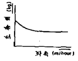
제4도는 얼터네이터 및 부하의 단자전압-충전전류 특성도.4 is a terminal voltage-charge current characteristic diagram of an alternator and a load.
제5도는 차속-조종력 특성도.5 is a vehicle speed-steering force characteristic diagram.
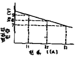
제6도는 배터리 수하 특성도.6 is a battery drop characteristic.
제7도는 배터리전압과 전류 제한치에 의한 패턴제어 특성도.7 is a pattern control characteristic diagram based on battery voltage and current limit values.
제8도는 본원 발명에 의한 전류 제한치 제어의 플로우차아트.8 is a flowchart of the current limit value control according to the present invention.
제9도는 파라미터가 아이들링 속도인 얼터네이터 및 부하의 단자전압-충전전류 특성을 나타낸 도면.9 shows terminal voltage-charge current characteristics of an alternator and a load whose parameters are idling speeds.
본원 발명은 자동차용 전동식 파워스테어링장치에 관한 것이며, 특히 배터리의 과방전을 방지하는데 적합한 전류제한방식에 의한 전동식 파워스테어링장치에 관한 것이다.BACKGROUND OF THE
종래, 자동차용의 파워스테어링자치로서 알려져 있는 것은 예를들면 1984년 12월 15일 일본국 특개소 59-223561호 공보에 개시되어 있는 "전동식 파워스테어링장치"와 같이, 모우터에 의해 오일펌프를 구동하고, 그 유압을 이용하여 핸들 조작력을 보조하는 이른바 전동 유압식 파워스테어링장치이다. 이러한 전동유압식 파워스테어링장치에 있어서는, 배터리의 과방전상태에 있어서는 모우터에의 전력공급을 차단하는 구성으로 되어 있기는 하지만, 자동차가 특히 고속으로 커어브를 주행하는 경우, 핸들이 중립위치에 되돌아오는 짧은 시간은 부적절하게 조작되는 위험을 지닌 구성으로 되어 있다. 파워스테어링기능을 충부히 유지한 다음에 배터리가 과방전상태로 되지 않도록 하는 점에 대해서는 아무런 배려도 되어 있지 않았었다.BACKGROUND ART Conventionally, known as power steering autonomous for automobiles, such as the "electric power steering apparatus" disclosed in Japanese Patent Laid-Open No. 59-223561 on December 15, 1984, for example, by a motor It is a so-called electro-hydraulic power steering device which drives a pump and assists a steering wheel operating force using the hydraulic pressure. In such an electro-hydraulic power steering device, although the battery is configured to cut off the power supply to the motor in an over-discharge state, the steering wheel is in a neutral position when the vehicle runs the curve at a particularly high speed. The short time to return is a configuration with the risk of improper manipulation. No consideration was given to ensuring that the battery would not be over discharged after the power steering function was fully maintained.
이것은 특히 핸들조작을 모우터동력에 의해 직접 보조하고자 하는 이른바 전동식 파워스테어링장치를 장비한 것에 있어서 현저하며, 과방전에 의해 헤드램프가 어두워진다는 따위의 결함이 생긴다.This is particularly remarkable when equipped with a so-called electric power steering device which directly supports steering wheel operation by motor power, and causes a defect such as darkening of the head lamp by over discharge.
본원 발명의 목적은 배터리전압저하에 의한 문제점을 해결하며, 배터리의 과방전을 방지하는 데 적합한 전동식 파워스테어링장치를 제공하는 데 있다.An object of the present invention is to solve the problem caused by the battery voltage drop, to provide an electric power steering device suitable for preventing the over-discharge of the battery.
본원 발명에 의하면, 상기 목적을 달성하기 위해, 전동식 파워스테어링장치의 모우터에 공급되는 전류를 배터리전압에 따라 제한함으로써 배터리전압을 소정치 이상으로 확보하는 것이다.According to the present invention, in order to achieve the above object, by limiting the current supplied to the motor of the electric power steering apparatus according to the battery voltage to ensure the battery voltage more than a predetermined value.
다음에, 본원 발명의 일실시예에 대해 설명한다. 제1도에 의하면 통상의 핸들조작시에 있어서는 핸들(1)에 의한 조작능력을 토오크센서(2)에 의해 조종토오크로서 거물하고, 이것을 콘트로울러(3)에 보낸다. 이 콘트로울러는 마이크로콤퓨터에 의해 구성된 것이다. 콘트로울러(3)는 토오크센서(2)의 검출시호에 따른 출력신호를 모우터(11)에 입력함으로써, 모우터(11)는 필요에 따른 토오크를 클러치(14)를 통해 감속기어(15)에 전달함으로써 핸들(1)의 조정력을 보조(어시스트)한다.Next, an embodiment of the present invention will be described. According to FIG. 1, in normal steering wheel operation, the operation capability by the
여기서, 모우터(11)는 직류 직권(直券)모우터이며, 우회전용 계자(界磁) 권선(7)과 좌회전용 계자권선(8)을 가지며 그 선택은 콘트로울러(3)로부터의 신호에 의해 제어되는 파워트랜지스터(9),(10)에 의해 행해진다. 또한, 모우터에 흐르는 전류를 검출하기 위한 전류검출기(4)가 설치되어 있다.Here, the
모우터구동용 전원은 차에 실린 배터리(12)이며, 엔진에 의해 회전구동되는 AC제네레이터의 얼터네이터(13)에 의해 충전된다. 배터리(12)에는 상기 모우터(11)의에, 헤드램프(80)나 다른 부하(60)가 각기 스위치(90),(70)를 통해 병렬로 접속되어 있다.The motor driving power source is a
이상의 구성에 의해, 핸들(1)에 있어서의 조종력이 스테어링기어(16)를 통해 전달된 힘과, 모우터(11)에서 감속기어(15)를 통해 전달된 힘과의 합성력에 의해, 타이어(17)에 조타각이 주어진다. 따라서, 토오크센서(2)가 토오크를 검출하는 한, 모우터(11)는 필요한 토오크를 발생하여 조종력을 보조하게 된다.By the above structure, by the combined force of the force transmitted to the
제1도의 핸들(1)에 가해진 조종토오크(T)에 의해, 토오크센서(2)에는 신호(Vc)가 출력된다. 이 토오크 센서신호(Vc)에 비례한 출력을 발생하는 비례출력 발생회로(19)로부터의 출력과 신호(Vc)의 미분치를 발생하는 미분출력 발생회로(18)로부터의 출력과의 합성치(Vcc)가 전류지령 발생회로(20)에 가해지며, 즉 조종토오크(T)에 의한 전류지령(Imc)이 결정된다.The signal V c is output to the torque sensor 2 by the control torque T applied to the
이것에 대해, 차속(S)에 의하여, 전류 제한치(ISL)가 차속-전류패턴제어회로(30)에 의해 결정되며, 다시 신호(Imc)와 (ISL)에 의해 전류지령(Ic)이 회로(21)에 의해 결정된다. 이 전류지령(Ic)은 전압지령회로(22)에 의해 지령전압(Vmc)으로 변환된다.On the other hand, the current limit value I SL is determined by the vehicle speed-current pattern control circuit 30 by the vehicle speed S, and the current command Ic by the signals I mc and I SL again. This is determined by the
다음에 지령전압(Vmc)에 대해, 실제로 모우터(11)에 흐르는 전류를 피이드백하여, 그 차가 쵸퍼회로(23)에 가해져 쵸퍼통류율(通流率) α가 결정된다. 이 통류율 α와 배터리전압(VB)과의 적(積)이 모우터(11)에 대한 입력전압(VM)으로 된다. 입력전압(VM)은 모우터저항(RM) 및 모우터시정시(τM)에 의한
![]()
![]()
또, 파워스테어링의 특징으로서 제5도에 나타낸 조종력과 차속의 관계가 있다. 정지시 핸들을 회전시킬 때와 같은 차속 0의 경우에 특히 커다란 조종력이 요구되는 것을 도면에서 알 수 있다. 이와같은 일로부터 정지시 핸들을 회전시킬 때에는 모우터(11)에는 대전류가 필요해진다. 또 정지상태에서 핸들을 좌우 어느쪽이거나 최대한으로 돌려 조종토오크를 계속 가할 경우나, 또는 최대토오크 상태에서 핸들을 유지했을 경우(예를들면 일부가 도랑에 빠진 차체를 꺼낼 때 등)에, 전류제한치(예를들면 50A)에 달하는 대전류가 필요해져서 많은 전력을 소비한다 더구나, 이와같은 정지시에 핸들을 회전시키는 동안의 엔진회전은 통상 아이들링상태이며, 얼터네이터(13)의 충전능력도 낮아져 있다. 얼터네이터(13)의 단자전압과 충전전류의 관계는 제4도의 곡선(A)에 나타낸 바와같이 되어 있으며, 이것에 전동식 파워스테어링장치 등의 전기부하가 걸리면 충전전류, 단자전압이 제4도의 곡선(B)에 나타낸 바와같이 모두 저하하게 된다. 이와같은 상황에서 종래의 전동식 파워스테어링장치에는 배터리의 과방전이 진행되어 엔진의 시동에 지장을 초래하거나, 헤드라이트가 어두워지나 기타의 보조기류(補助機類)가 정상적으로 동작하지 않거나, 콘트로울러의 오동작을 일으킨다는 등의 실용상 및 안전상의 문제가 있었다. 여기서, 종래의 전기부하는 헤드라이트에서도 15[A]정도이며, 그것에 대해 전동식 파워스테어링장치는 최대전류 50[A]라고 하는 대전류를 필요로 하는 것이다. 따라서, 전동식 파워스테어링장치 장착차에 있어서는 배터리(12)의 전압확보가 특히 필요한 해결되어야 할 중요한 과제로 되어 있다.In addition, as a characteristic of the power steering, there is a relationship between the steering force shown in FIG. 5 and the vehicle speed. It can be seen from the figure that particularly large steering forces are required in the case of vehicle speed 0, such as when turning the steering wheel at rest. In such a case, when rotating the handle at the stop, a large current is required for the
본원 발명에 있어서는 전압확보를 위해, 급전라인의 어느 한쪽의 전압을 검출하고, 이 값에 따라 모우터(11)의 전류제한을 한다. 여기서, 급전라인이란 제3도의 실선으로 나타낸 부분이다. 따라서, 플러스측도 급전라인이며, 마이너스측도 급전라인이다. 한 예로서, 전압검출을 급전라인중의 배터리단자에서 했을 경우를 설명한다.In the present invention, to secure the voltage, one of the voltages of the power supply line is detected, and the current limit of the
제6도에 본 실시예에 의한 전동식 파워스테어링장치의 배터리의 전압수하(垂下) 특성을 나타낸다. 이 도면에도 나타낸 바와 같이, 배터리의 과방전이 진행되면, 배터리 단자전압이 7[V]이하로 저하하는 경우가 있다. 제6도에 의하면, 전류(I3)[A]에서 전압이 VB=7A[V]일지라도, 전류를 (I1)[A]까지 낮추면 VB=9[V]까지 회복한다. 본원 발명에서는 이와 같은 배터리 특유의 현상에 의거하여, 전류를 제한하는 것, 더욱 구체적으로는 제어회로에 있어서의 전류제한치를 낮춤으로써 배터리전압을 확보하려고 하는 것이며, 그것을 위한 적절한 전동식 파워스테어링장치를 제공하려고 하는 것이다.6 shows the voltage drop characteristic of the battery of the electric power steering apparatus according to the present embodiment. As also shown in this figure, when the overdischarge of the battery proceeds, the battery terminal voltage may drop below 7 [V]. According to FIG. 6, even if the voltage in the current I 3 [A] is V B = 7 A [V], when the current is lowered to (I 1 ) [A], V B = 9 [V] is recovered. In the present invention, on the basis of such battery-specific phenomena, it is intended to ensure battery voltage by limiting the current, more specifically by lowering the current limit in the control circuit. Is to provide.
이를 위한 방식으로서, 예를들면 제7도에 나타낸 바와같이, 배터리전압에 대응하는 전류 제한치에 의한 이른바 패턴제어를 채용한다. 구체적으로는 배터리전압을 검출하고, 그 검출치에 대응해서 전류제한치를 설정하는 방법이며, 예를들면 배터리전압 VB=10[V]이면 전류제한치는 25[A]로 되어, 이 경우 28[A]이하의 범위에서 모우터에 공급되는 전류를 제어한다. 또한, 배터리전압이 VB=7.5[V]이하로 저하했을 경우에는 배터리의 과방전을 방지하기위해, 모우터전류를 차단하게 된다. 이와 같은 패턴제어는 콘트로울러(3)를 구성하는 마이크로콤퓨터의 ROM(리이드온리메모리)에 제7도에 나타낸 특성을 기억해 두고, 이것을 독출함으로써 행해진다.As a scheme for this purpose, for example, as shown in Fig. 7, a so-called pattern control by current limit value corresponding to the battery voltage is adopted. Specifically, the battery voltage is detected and a current limit value is set corresponding to the detected value. For example, if the battery voltage V B = 10 [V], the current limit value is 25 [A], in which case 28 [ A] Control the current supplied to the motor within the following range. In addition, when the battery voltage drops below V B = 7.5 [V], the motor current is cut off to prevent over discharge of the battery. Such pattern control is performed by storing the characteristic shown in FIG. 7 in the ROM (lead only memory) of the microcomputer constituting the controller 3 and reading it out.
이와 같은 패턴제어에 의해 모우터전류를 배터리전압에 따라 제어하는 것과, 또한 얼터네이터(13)에 의한 배터리(12)의 충전에 의해, 배터리(12)가 다시 12[V]이상으로 회복하면, 정상대로 50[A]의 전류제한치로 모우터(11)를 제어한다.By controlling the motor current according to the battery voltage by such a pattern control and charging the
그러나, 단지 이와 같은 패턴제어만으로는 헌팅을 일으키는 경우가 생기며, 본 실시예에서는 다시 피이드백 제어에 의해 설정전압으로 되도록 모우터전류를 제어하는 방법을 채용하고 있다.However, only such pattern control may cause hunting. In this embodiment, a method of controlling the motor current so as to be a set voltage by feedback control is employed.
이 피이드백제어를 제8도의 플로우차아트에 의해 구체적으로 나타낸다. 제8도에 나타낸 플로우차아트는 제2도에 나타낸 전류 제한회로(29)에 의하여 행해진다.This feedback control is concretely shown by the flowchart art of FIG. The flowchart art shown in FIG. 8 is performed by the current limiting circuit 29 shown in FIG.
제8도에 나타낸 단계(33)에 의하여 제어가 시작된 후, 단계(34)에서 배터리(12)의 단자전압이 검출된다. 단계(35)에서 모우터의 조작이 모우드 1-3의 어느것에 상응 하는가를 판정한다.After the control is started by step 33 shown in FIG. 8, in step 34, the terminal voltage of the
절대로 확보해야 할 배터리전압(VB)을 7.5[V]로서 설정하면, VB<7.5[V]의 경우는 모우터전류를 차단하지 않을 수 없다. 그러나 모우터전류를 차단하면 파워스테어링의 기능이 상실되는 것이 문제이다. 그래서, 배터리전압이 VB<7.5[V]가 되지 않도록, 다시 VB=8[V]와 VB=8.5[V]와 VB=9[V]를 설정하고, 단계(36)에 나타낸 모우드(1)의 7.5[V]<VB<8[V]의 범위에서는 0.2[S]마다 1.7[A]씩 전류제한치를 낮추어 간다. 여기서, 시간과 전류치를 작게 나누는 것은 전류제한치의 변화에 의해 생기는 운전자에게 주는 쇼크를 줄이기 위해서이며, 전류제한치를 낮춘 결과, 단계(37)에 나타낸 모우드(2)의 8.5[V]<VB<9[V]까지 배터리전압이 회복하면, 그 시점에서의 전류제한치(IBL)[A]에 의해 모우터를 제어한다. 또한 배터리전압(VB)이 얼터네이터의 충전과의 관계로 단계(38)에 나타낸 모우드(3)의 VB>9[V]로 되면 반대로 0.2[S]마다 전류제한치를 1.7[A]씩 올려 간다. 그리고 배터리전압 VB>12[V]의 경우는 무조건 50[A]의 전류제한치에 의해 파워스테어링의 기능을 발휘한다.If the battery voltage (V B ) that must be secured is set to 7.5 [V], the motor current must be shut off when V B <7.5 [V]. However, if the motor current is blocked, the function of power steering is lost. Thus, V B = 8 [V] and V B = 8.5 [V] and V B = 9 [V] are set again so that the battery voltage does not become V B <7.5 [V], and is shown in step 36. In the range of 7.5 [V] <V B <8 [V] of the
한편, 배터리(12)에 의하여 구동되는 모우터(11)를통하여 흐르는 전류(IM)에 따라, 배터리전압(VB)은 제6도에 나타낸 수하특성에 의거 저하된다.On the other hand, with the current I M flowing through the
이상 기술한 바와같이, 본원 발명에 의하면, 제2도에 있어서의 전류제한회로(29)를 추가함으로써 파워스테어링장치로서의 최저한의 기능을 확보한 다음에, 다시 배터리의 과방전을 방지할 수 있다.As described above, according to the present invention, by adding the current limiting circuit 29 in FIG. 2, the minimum function as the power steering apparatus can be ensured, and then the overdischarge of the battery can be prevented again.
또한 본원 발명에 의하면, 배터리(12)의 전압확보를 위해, 모우터전류가 설정된 전류제한치(예를들면 50A)에 달한 경우를 검출하여, 이 검출신호를 얼터네이터(13)의 발전을 가세하는 제어신호로서 이용하는 것이다. 즉, 제1도에 있어서, 모우터전류가 전류제한치에 달하면, 이것을 전류검출기(4)로 검출하고, 이 검출신호에 의해 콘트로울러(3)를 통해 아이들링 회전수제어장치(50)를 동작시켜 엔진의 아이들링 회전수를 올림으로써 얼터네이터(13)의 충전능력을 높이는 것이다. 제9도에는 얼터네이터(13) 및 부하의 단자전압과 충전전류와의 관계가 나타나 있으며, 곡선(A) 및 (B)는 각각 얼터네이터 및 부하에 대응한다. 아이들링 회전수가 증가함에 따라 얼터네이터의 단자전압 대 충전전류의 특성은 화살표 방향으로 이동한다.Further, according to the present invention, in order to secure the voltage of the
이때 엔진회전수가 단시간에 변동하면 운전자에 대해 불쾌감을 주기 때문에, 본 실시예에 있어서는 타이머(40)를 이용하여 아이들링 회전수를 증가시키는 시간을 3분간으로 설정하고 있다. 본원 발명에서는 아이들링 회전수 제어장치(50)를 전동식 파워스테어링장치에 사용하고 있으며, 그 상세한 것은 나타내지 않지만, 모우터(11)의 전류가 상기 전류제한치에 달했을 경우에 동작시켜, 배터리의 과방전을 방지하는 것이다. 즉, 이 아이들링 회전수 제어장치(50)는 얼터네이터(13)의 회전속도(N)가 설정회전속도(No)보다도 낮고, 또한 충전발전기의 계자전류(If)가 설정전류(Ifo)보다 클 때, 스로틀밸브의 개도를 증가시켜, 아이들링 회전속도가 증가하여 충전발전기의 회전속도가 상승하는 것이다.At this time, if the engine speed changes in a short time, the driver is offended. Therefore, in this embodiment, the time for increasing the idling speed using the
이상과 같이, 전류제한치를 바꾸어 배터리전압을 보호하는 데다가 다시 모우터전류제한치에 달했을 경우에는 엔진의 아이들링 회전수를 올려 얼터네이터(13)에 의한 충전을 가세함으로써 배터리(12)의 과방전을 방지할 수 잇다. 본원 발명의 실시예에 의하면 모우터 전류제한과 동시에 엔진의 회전수를 증가시켜 얼터네이터의 충전능력을 높일 수 있다.As described above, when the current limit value is changed to protect the battery voltage and the motor current limit value is reached again, the engine idling speed is increased to add charge by the alternator 13 to prevent over discharge of the
Claims (7)
Applications Claiming Priority (3)
| Application Number | Priority Date | Filing Date | Title |
|---|---|---|---|
| JP126100 | 1985-06-12 | ||
| JP12610085A JPH0615331B2 (en) | 1985-06-12 | 1985-06-12 | Electric power steering device |
| JP?60-126100 | 1985-06-12 |
Publications (2)
| Publication Number | Publication Date |
|---|---|
| KR870000205A KR870000205A (en) | 1987-02-17 |
| KR900005709B1 true KR900005709B1 (en) | 1990-08-06 |
Family
ID=14926611
Family Applications (1)
| Application Number | Title | Priority Date | Filing Date |
|---|---|---|---|
| KR1019860004421A KR900005709B1 (en) | 1985-06-12 | 1986-06-04 | Motor-driven power steering apparatus |
Country Status (5)
| Country | Link |
|---|---|
| US (1) | US4756375A (en) |
| JP (1) | JPH0615331B2 (en) |
| KR (1) | KR900005709B1 (en) |
| DE (1) | DE3619703A1 (en) |
| GB (1) | GB2177358B (en) |
Cited By (2)
| Publication number | Priority date | Publication date | Assignee | Title |
|---|---|---|---|---|
| KR100563727B1 (en) * | 2004-06-02 | 2006-03-28 | 미츠비시덴키 가부시키가이샤 | Motor driven power steering apparatus |
| KR102139498B1 (en) * | 2019-05-28 | 2020-07-30 | 한국생산기술연구원 | Four-wheel steering system with fault coping function of rear wheel steering system and its operation method |
Families Citing this family (56)
| Publication number | Priority date | Publication date | Assignee | Title |
|---|---|---|---|---|
| JPH0615331B2 (en) * | 1985-06-12 | 1994-03-02 | 株式会社日立製作所 | Electric power steering device |
| JPH06506B2 (en) * | 1987-03-04 | 1994-01-05 | 三菱電機株式会社 | Motor drive type power steering control method |
| US4751978A (en) * | 1987-03-16 | 1988-06-21 | Trw Inc. | Electric assist steering system with alternator power source |
| GB2204287B (en) * | 1987-03-31 | 1991-04-17 | Hitachi Ltd | Electric power steering control system |
| JP2532105B2 (en) * | 1987-09-17 | 1996-09-11 | 本田技研工業株式会社 | Steering control device for front and rear wheel steering vehicles |
| JPH01233165A (en) * | 1988-03-15 | 1989-09-18 | Fuji Heavy Ind Ltd | Control method for motor-operated power steering device for vehicle |
| US5150021A (en) * | 1989-09-18 | 1992-09-22 | Jidosha Kiki Co., Ltd. | Method of controlling electric power steering apparatus |
| JP2948887B2 (en) * | 1990-09-07 | 1999-09-13 | 株式会社日立製作所 | Motor speed control device |
| JPH04145886A (en) * | 1990-10-02 | 1992-05-19 | Toshiba Corp | Speed control method and apparatus for motor |
| FR2676982B1 (en) * | 1991-05-29 | 1998-01-02 | Valeo Electronique | ELECTRIC POWER STEERING DEVICE FOR VEHICLE. |
| DE69217280T2 (en) * | 1991-07-10 | 1997-05-28 | Koyo Seiko Co | Steering with an electric assistant |
| US5227703A (en) * | 1992-04-21 | 1993-07-13 | General Electric Company | Protection system for alternating current, battery powered electric traction motor vehicle |
| JP2949183B2 (en) * | 1992-11-25 | 1999-09-13 | 光洋精工株式会社 | Electric power steering device |
| US5406778A (en) * | 1994-02-03 | 1995-04-18 | Ransomes America Corporation | Electric drive riding greens mower |
| US5473231A (en) * | 1994-05-11 | 1995-12-05 | Trw Inc. | Method and apparatus for controlling an electric assist steering system using an adaptive torque filter |
| DE4418118C1 (en) * | 1994-05-24 | 1995-07-06 | Daimler Benz Ag | Servo steering control for automobile |
| JP3479730B2 (en) * | 1994-10-20 | 2003-12-15 | 光洋精工株式会社 | Electric power steering device |
| US6035960A (en) * | 1995-01-26 | 2000-03-14 | Kayaba Industry Co., Ltd. | Motorized power steering control device |
| JP3460885B2 (en) * | 1995-03-09 | 2003-10-27 | 三菱電機株式会社 | Electric power steering control device |
| US6094011A (en) * | 1995-06-26 | 2000-07-25 | Kokusan Denki Co., Ltd | Discharge lamp lighting device driven by internal combustion engine |
| US6082084A (en) | 1995-11-13 | 2000-07-04 | Ransomes America Corporation | Electric riding mower with electric steering system |
| US5794422A (en) * | 1995-11-13 | 1998-08-18 | Ransomes America Corporation | Electric drive mower with motor generator set |
| US5934051A (en) * | 1997-02-06 | 1999-08-10 | Textron, Inc. | Solid state mow system for electrically powered mower |
| JP3951337B2 (en) * | 1997-02-25 | 2007-08-01 | 日本精工株式会社 | Control device for electric power steering device |
| JPH11147479A (en) * | 1997-11-18 | 1999-06-02 | Mitsubishi Electric Corp | Electric power steering unit |
| US6109009A (en) | 1998-01-16 | 2000-08-29 | Textron Inc. | Constant speed control for electric greens mower |
| US6068078A (en) * | 1998-06-16 | 2000-05-30 | Trw Inc. | Electric steering system |
| KR20020043069A (en) * | 2000-12-01 | 2002-06-08 | 밍 루 | Apparatus for controlling a motor in electronic power steering system |
| JP4060051B2 (en) * | 2001-07-27 | 2008-03-12 | 株式会社ジェイテクト | Power steering device |
| US6647330B1 (en) * | 2002-04-30 | 2003-11-11 | Visteon Global Technologies, Inc. | Electronic power assisted steering system and method |
| JP4294380B2 (en) * | 2003-06-04 | 2009-07-08 | 株式会社ジェイテクト | Vehicle steering system |
| DE10325848A1 (en) * | 2003-06-06 | 2005-01-05 | Trw Fahrwerksysteme Gmbh & Co. Kg | Method for controlling an electric pump drive motor of a power steering device |
| US7168227B2 (en) * | 2004-05-21 | 2007-01-30 | Textron Inc. | Internal combustion engine traction drive with electric cutting unit drive for walking greens mower |
| JP4517734B2 (en) | 2004-06-03 | 2010-08-04 | 日本精工株式会社 | Electric power steering device |
| JP4352268B2 (en) * | 2005-10-21 | 2009-10-28 | トヨタ自動車株式会社 | Electric power steering device |
| US7392869B2 (en) * | 2005-11-01 | 2008-07-01 | Textron Inc. | Modular power source for riding mower |
| JP4666623B2 (en) * | 2005-11-24 | 2011-04-06 | 株式会社デンソー | Electric power steering device |
| JP2007161157A (en) * | 2005-12-15 | 2007-06-28 | Nsk Ltd | Electric power steering device |
| JP2007210365A (en) * | 2006-02-07 | 2007-08-23 | Toyota Motor Corp | Power steering control device |
| JP5034375B2 (en) * | 2006-08-25 | 2012-09-26 | 日本精工株式会社 | Electric power steering device |
| JP4333743B2 (en) * | 2007-01-10 | 2009-09-16 | トヨタ自動車株式会社 | Steering device |
| US7854293B2 (en) | 2007-02-20 | 2010-12-21 | Textron Innovations Inc. | Steering operated by linear electric device |
| FR2917034B1 (en) * | 2007-06-06 | 2009-10-30 | Renault Sas | METHOD FOR CONTROLLING THE POWER SUPPLY OF ORGANS OF A VEHICLE AND CONTROL SYSTEM FOR ITS IMPLEMENTATION |
| US8521384B2 (en) * | 2008-01-28 | 2013-08-27 | Textron Innovations Inc. | Turf maintenance vehicle all-wheel drive system |
| JP5343599B2 (en) | 2009-02-10 | 2013-11-13 | 株式会社ジェイテクト | Motor control device and electric power steering device |
| DE102009013246B4 (en) * | 2009-03-14 | 2014-02-13 | Audi Ag | Method for providing information about the operating state of a steering system |
| DE102009057064B4 (en) * | 2009-12-04 | 2019-07-18 | Audi Ag | Vehicle with a power steering and method of operating such |
| GB201006395D0 (en) * | 2010-04-16 | 2010-06-02 | Dyson Technology Ltd | Control of a brushless motor |
| GB201006388D0 (en) | 2010-04-16 | 2010-06-02 | Dyson Technology Ltd | Control of brushless motor |
| GB201006397D0 (en) | 2010-04-16 | 2010-06-02 | Dyson Technology Ltd | Control of a brushless motor |
| JP2012166746A (en) * | 2011-02-16 | 2012-09-06 | Jtekt Corp | Electric power steering system |
| US8727067B2 (en) * | 2011-06-30 | 2014-05-20 | Ford Global Technologies, Llc | Method for supplying power to an electrically assisted steering system |
| GB201218674D0 (en) * | 2012-10-17 | 2012-11-28 | Trw Ltd | Control strategy for a motor of an electric assisted steering system |
| GB201308249D0 (en) * | 2013-05-08 | 2013-06-12 | Trw Ltd | Method of controlling a motor of an electric power assisted steering system |
| DE102014200528A1 (en) * | 2014-01-14 | 2015-07-16 | Ford Global Technologies, Llc | A method of operating an electric steering assistance for a motor vehicle and electric steering assistance and correspondingly equipped motor vehicle |
| KR101588781B1 (en) * | 2014-10-21 | 2016-01-26 | 현대자동차 주식회사 | Electricity generation mode control method of vehicle |
Family Cites Families (21)
| Publication number | Priority date | Publication date | Assignee | Title |
|---|---|---|---|---|
| JPS5249135B2 (en) * | 1973-11-07 | 1977-12-15 | ||
| FR2492759A1 (en) * | 1980-10-27 | 1982-04-30 | Citroen Sa | IMPROVEMENTS RELATING TO ROTARY ASSISTANCE MECHANISMS, IN PARTICULAR FOR VEHICLE STEERING |
| JPS5843102A (en) * | 1981-09-03 | 1983-03-12 | Mitsubishi Electric Corp | Power source for cooling vehicle |
| JPS5869403A (en) * | 1981-10-20 | 1983-04-25 | Daihatsu Motor Co Ltd | Controller for hybrid vehicle |
| JPS58104339A (en) * | 1981-12-15 | 1983-06-21 | Nissan Motor Co Ltd | Stabilizer of idling of vehicle |
| JPS5911965A (en) * | 1982-07-13 | 1984-01-21 | Nippon Seiko Kk | Electric power steering device |
| JPS5938168A (en) * | 1982-08-26 | 1984-03-01 | Mazda Motor Corp | Power steering device |
| JPS5956348U (en) * | 1982-10-07 | 1984-04-12 | 株式会社ボッシュオートモーティブ システム | Idle operation control device |
| JPS5970257A (en) * | 1982-10-14 | 1984-04-20 | Aisin Seiki Co Ltd | Motor-driven power steering device |
| JPS5994977U (en) * | 1982-12-20 | 1984-06-27 | マツダ株式会社 | Electric power steering vehicle power control device |
| JPS59130780A (en) * | 1983-01-17 | 1984-07-27 | Aisin Seiki Co Ltd | Motor-driven power steering device |
| US4532567A (en) * | 1983-02-18 | 1985-07-30 | General Motors Corporation | Electric power steering stall protection circuit |
| JPH0624939B2 (en) * | 1983-06-01 | 1994-04-06 | 東海ティーアールダブリュー株式会社 | Electric power steering device |
| JPS6080969A (en) * | 1983-10-13 | 1985-05-08 | Nissan Motor Co Ltd | Power steering gear |
| JPH0777870B2 (en) * | 1984-01-09 | 1995-08-23 | 防衛庁技術研究本部長 | Turning control method for hydromechanical transmission / steering unit |
| JPS60197464A (en) * | 1984-03-22 | 1985-10-05 | Nippon Seiko Kk | Electrically driven type power steering apparatus |
| US4624334A (en) * | 1984-08-30 | 1986-11-25 | Eaton Corporation | Electric power assisted steering system |
| JPS61105272A (en) * | 1984-10-26 | 1986-05-23 | Honda Motor Co Ltd | Magnetic booster |
| JPS61155056A (en) * | 1984-12-27 | 1986-07-14 | Toyoda Mach Works Ltd | Electric type power steering device |
| JPS61172866U (en) * | 1985-04-16 | 1986-10-27 | ||
| JPH0615331B2 (en) * | 1985-06-12 | 1994-03-02 | 株式会社日立製作所 | Electric power steering device |
-
1985
- 1985-06-12 JP JP12610085A patent/JPH0615331B2/en not_active Expired - Lifetime
-
1986
- 1986-06-04 KR KR1019860004421A patent/KR900005709B1/en not_active IP Right Cessation
- 1986-06-04 US US06/870,751 patent/US4756375A/en not_active Expired - Fee Related
- 1986-06-10 GB GB08614067A patent/GB2177358B/en not_active Expired
- 1986-06-12 DE DE19863619703 patent/DE3619703A1/en active Granted
Cited By (2)
| Publication number | Priority date | Publication date | Assignee | Title |
|---|---|---|---|---|
| KR100563727B1 (en) * | 2004-06-02 | 2006-03-28 | 미츠비시덴키 가부시키가이샤 | Motor driven power steering apparatus |
| KR102139498B1 (en) * | 2019-05-28 | 2020-07-30 | 한국생산기술연구원 | Four-wheel steering system with fault coping function of rear wheel steering system and its operation method |
Also Published As
| Publication number | Publication date |
|---|---|
| KR870000205A (en) | 1987-02-17 |
| DE3619703A1 (en) | 1987-01-02 |
| GB2177358A (en) | 1987-01-21 |
| DE3619703C2 (en) | 1990-04-26 |
| GB8614067D0 (en) | 1986-07-16 |
| JPS61285171A (en) | 1986-12-15 |
| US4756375A (en) | 1988-07-12 |
| JPH0615331B2 (en) | 1994-03-02 |
| GB2177358B (en) | 1988-08-03 |
Similar Documents
| Publication | Publication Date | Title |
|---|---|---|
| KR900005709B1 (en) | Motor-driven power steering apparatus | |
| EP1151892B1 (en) | Vehicle with a high voltage power source system and method of controlling the start of such vehicle | |
| US6335574B1 (en) | Control apparatus for hybrid vehicle | |
| CN101279602B (en) | Vehicular system capable of suitably controlling engine speed and gear ratio according to battery charge state | |
| US5086859A (en) | Method and system for controlling electric power steering | |
| JP2000030753A (en) | Control device of battery for hybrid vehicle | |
| EP0361726A2 (en) | Motorized power steering apparatus | |
| US4508999A (en) | Short circuit protection apparatus | |
| US4869333A (en) | Motor-driven type power steering control device | |
| CA2160941A1 (en) | Electrically propelled vehicule | |
| CN102248900A (en) | Methods and system for motor torque control for vehicles when current sensor is not operating properly | |
| EP3971056A2 (en) | Electric power source device | |
| EP0399405B1 (en) | Motor-driven type front and rear wheel steering apparatus | |
| JPS59149870A (en) | Power steering gear | |
| JP3949047B2 (en) | Vehicle control device | |
| JP3178139B2 (en) | Control device for electric vehicle | |
| JP3532438B2 (en) | Hybrid vehicle | |
| JPH0624939B2 (en) | Electric power steering device | |
| KR100559316B1 (en) | A driving system of vehicle and controlling method thereof | |
| JPH08336237A (en) | Electric load controller for working machine | |
| JP4519428B2 (en) | Vehicle power supply system | |
| JPH0664550A (en) | Power steering control device | |
| JPH06261419A (en) | Controller for engine driven generator in electric automobile | |
| JP3028715B2 (en) | Electric car | |
| JP4797714B2 (en) | Motor over-rotation prevention device for electric motor type four-wheel drive vehicle |
Legal Events
| Date | Code | Title | Description |
|---|---|---|---|
| A201 | Request for examination | ||
| E902 | Notification of reason for refusal | ||
| G160 | Decision to publish patent application | ||
| E701 | Decision to grant or registration of patent right | ||
| GRNT | Written decision to grant | ||
| LAPS | Lapse due to unpaid annual fee |