KR900001032B1 - Remote supersisory and controlling system - Google Patents
Remote supersisory and controlling system Download PDFInfo
- Publication number
- KR900001032B1 KR900001032B1 KR1019860009960A KR860009960A KR900001032B1 KR 900001032 B1 KR900001032 B1 KR 900001032B1 KR 1019860009960 A KR1019860009960 A KR 1019860009960A KR 860009960 A KR860009960 A KR 860009960A KR 900001032 B1 KR900001032 B1 KR 900001032B1
- Authority
- KR
- South Korea
- Prior art keywords
- signal
- terminal device
- input
- data
- control
- Prior art date
Links
Images


Classifications
-
- G—PHYSICS
- G05—CONTROLLING; REGULATING
- G05G—CONTROL DEVICES OR SYSTEMS INSOFAR AS CHARACTERISED BY MECHANICAL FEATURES ONLY
- G05G7/00—Manually-actuated control mechanisms provided with one single controlling member co-operating with one single controlled member; Details thereof
- G05G7/02—Manually-actuated control mechanisms provided with one single controlling member co-operating with one single controlled member; Details thereof characterised by special provisions for conveying or converting motion, or for acting at a distance
- G05G7/10—Manually-actuated control mechanisms provided with one single controlling member co-operating with one single controlled member; Details thereof characterised by special provisions for conveying or converting motion, or for acting at a distance specially adapted for remote control
-
- H—ELECTRICITY
- H04—ELECTRIC COMMUNICATION TECHNIQUE
- H04Q—SELECTING
- H04Q9/00—Arrangements in telecontrol or telemetry systems for selectively calling a substation from a main station, in which substation desired apparatus is selected for applying a control signal thereto or for obtaining measured values therefrom
- H04Q9/14—Calling by using pulses
-
- G—PHYSICS
- G05—CONTROLLING; REGULATING
- G05B—CONTROL OR REGULATING SYSTEMS IN GENERAL; FUNCTIONAL ELEMENTS OF SUCH SYSTEMS; MONITORING OR TESTING ARRANGEMENTS FOR SUCH SYSTEMS OR ELEMENTS
- G05B11/00—Automatic controllers
- G05B11/01—Automatic controllers electric
Landscapes
- Engineering & Computer Science (AREA)
- Computer Networks & Wireless Communication (AREA)
- Physics & Mathematics (AREA)
- General Physics & Mathematics (AREA)
- Automation & Control Theory (AREA)
- Selective Calling Equipment (AREA)
- Small-Scale Networks (AREA)
Abstract
Description
제1도는 본 발명에 다른 원격감시 및 에어시스템의 일반적인 배치를 개략적으로 나타내는 부분 블록도.1 is a partial block diagram schematically illustrating a general arrangement of a remote monitoring and air system according to the present invention.
제2도는 제1도의 시스템에서 중앙제어장치 및 각 동작, 감시 및 제어장치의 실제 배선예.2 is an example of the actual wiring of the central control unit and each operation, monitoring and control unit in the system of FIG.
제3도는 제1도의 시스템이 다층빌딩에 적용된 실제예의 개략단면도.3 is a schematic sectional view of a practical example in which the system of FIG. 1 is applied to a multi-story building.
제4도는 판넬에 연결된 동작터미날장치와 함께 제1도의 시스템에서 중앙제어장치 및 제어터미날장치를 포함하는 상세한 제어판낼을 나타내는 회로도.4 is a circuit diagram showing a detailed control panel including a central control unit and a control terminal unit in the system of FIG. 1 with an operating terminal device connected to a panel.
제5도는 제4도의 그것에 대체로 대응하는 제어판낼의 확대투시도.5 is an enlarged perspective view of the control panel generally corresponding to that of FIG.
제6도는 제1도의 시스템에서 중앙제어장치의 회로도를 나타낸 예.6 shows an example of a circuit diagram of a central controller in the system of FIG.
제7a도는 제1도에 있는 중앙제어장치 수단에 의해 끊임없이 제공되는 더미 전송신호의 파형도.FIG. 7A is a waveform diagram of a dummy transmission signal constantly provided by the central control means in FIG.
제7b도는 제1도의 시스템에 있는 동작터미날장치로부터의 개입 중단신호의 예를 나타내는 파형도.7B is a waveform diagram showing an example of an interruption stop signal from an operation terminal device in the system of FIG.
제8도는 제1도의 시스템에 있는 제어터미날장치의 예를 나타내는 회로도.8 is a circuit diagram showing an example of a control terminal device in the system of FIG.
제9도는 제1도의 시스템에 있는 동작터미날장치의 블록도.9 is a block diagram of an operating terminal device in the system of FIG.
제10도는 제1도의 시스템에 있는 원격제어스위치의 예를 나타내는 회로도.10 is a circuit diagram illustrating an example of a remote control switch in the system of FIG.
제11도는 제1도의 시스템에 있는 동작터미날장치의 실제예를 나타내는 사시도.11 is a perspective view showing a practical example of an operation terminal device in the system of FIG.
제12도는 제1도의 시스템에 있는 중앙제어장치, 동작 및 감시터미날장치 사이의 동작관계를 나타내는 흐름도.FIG. 12 is a flow chart showing the operational relationship between a central control unit, an operation and a monitoring terminal device in the system of FIG.
제13도는 제1도의 시스템에 있는 동작 및 감시터미날장치에 대한 중앙제어장치의 동작을 나타내는 흐름도.13 is a flow chart showing the operation of the central control unit with respect to the operation and supervisory terminal device in the system of FIG.
제14도는 제1도의 시스템에 있는 동작터미날장치에 대한 중앙제어장치의 동작을 나타내는 흐름도.FIG. 14 is a flow chart showing operation of the central control unit with respect to the operating terminal device in the system of FIG.
* 도면의 주요부분에 대한 부호의 설명* Explanation of symbols for main parts of the drawings
10 : 중앙제어장치 12, 13, 14 : 터미널장치10:
15 : 부하15: load
본 발명은 원격감시 및 제어시스템에 관한 것이다. 특히 입력과 제어데이타 사이에 시분할 다중 전송용 중앙제어장치에 2전선 신호선을 통해 연결된 다수의 동작, 감시 및 제어터미날장치를 각각 원격으로 감시 및 제어하는 시스템에 관한 것이다.The present invention relates to a remote monitoring and control system. In particular, the present invention relates to a system for remotely monitoring and controlling a plurality of operation, monitoring and control terminal devices respectively connected via a two-wire signal line to a central control unit for time division multiple transmission between input and control data.
원격감시 및 제어시스템은 다수의 제어터미날장치는 물론 다수의 동작 및 감시 터미널장치("입력터미날장치"라고도 부름)를 중앙 집중화하여 제어함으로써, 원격제어방으로부터 다층 빌딩내의 여러 장소에 위치한 다수의 입력터미날장치에 연결된 예를들어 조명기구, 검출기등과 같은 많은 부하를 제어하는데 효과적으로 유용하다.The remote monitoring and control system centralizes and controls a large number of control terminal devices as well as a number of operating and monitoring terminal devices (also called input terminal devices), allowing multiple inputs located in multiple locations within a multi-story building from a remote control room. It is effectively useful for controlling many loads such as luminaires, detectors, etc. connected to terminal devices.
일반적으로 원격감시 및 제어를 수행하는데 있어, 예를들어 와이, 고지마(Y. Kojima) 등의 미국 특허번호 4,608,561에 개시된 시분할 다중전송을 채용한 부하 제어시스템을 이용하는 것이 가능하다. 간단히 요약하면 상기 특허는 다수의 터미널장치가 양 자동 및 수동식방식에 있어서 2웨이 자유제어를 위해 중앙제어장치에 연결된 배치를 나타내며, 그러한 배치는 터미널장치의 제어의 자유를 확장할 수 있는 장점이 있을 수 있다.In general, in performing remote monitoring and control, it is possible to use a load control system employing time division multiplexing disclosed in, for example, US Patent No. 4,608,561 to Y. Kojima et al. In short, the patent shows an arrangement in which a plurality of terminal devices are connected to a central control unit for two-way free control in both automatic and manual manners, which arrangement may have the advantage of extending the freedom of control of the terminal device. Can be.
본 특허에서 중앙제어장치를 주기적으로 터미널장치에 억세스하여 입력 및 제어신호 데이터의 시분할 다중전송을 수행하는 중앙제어장치에 의한 자동제어가 실행된다. 그러나 중앙제어장치가 수적으로 증가함에 의해 터미널장치가 제어될 때 시스템의 응답이 데이터 입력이 타이밍에 따라서 불리하게 지연되는 문제가 발생된다.In this patent, the automatic control by the central controller which performs time division multiplexing of input and control signal data by periodically accessing the central controller to the terminal apparatus is executed. However, the increase in the number of central controllers causes a problem that the response of the system is adversely delayed depending on the timing when the terminal apparatus is controlled.
즉 중앙제어장치에 의해 제어되도록 128 터미널장치가 제공되며, 128 채널 어드레스가 세트되면 1번째부터 128번째까지의 순서적 억세스가 이루어지며, 만약 중앙제어장치가 억세스동안 제1채널에 대응하는 입력터미날장치의 하나로부터 제2채널에 데이터 입력을 수신할 경우, 제1채널이 다음 사이클에 종속될때까지 필요한 시간(T)은 T=127To로 표현되며 이때 To는 각 터미널장치의 억세스 시간이며, 그리고 중앙제어장치에 의해 수신된 입력데이타는 현저히 지연될 것이다.That is, 128 terminal devices are provided to be controlled by the central control unit, and when the 128 channel address is set, the first to 128th ordered accesses are made, and if the central control unit accesses the input terminal corresponding to the first channel during the access. When receiving data input from one of the devices to the second channel, the time T required until the first channel is dependent on the next cycle is represented by T = 127To, where To is the access time of each terminal device, and center The input data received by the controller will be significantly delayed.
특히 원격감시 및 제어시스템이 센서로부터의 비정상신호에 응하여 하나 이상의 광장치를 켜기 위한 감시 터미널장치로서 합체된 침입(intruder)센서와 관련되어 다층 빌딩내에서 많은 광장치의 제어를 중앙집중화 하는데 적용될 경우, 최후의 광을 위해 필요한 시간이 너무 길어 시스템이 충분히 효과적이지 못하게 하는 위험이 수반된다.In particular, when a remote monitoring and control system is applied to centralize the control of many optical devices in a multi-storey building in conjunction with an intruder sensor integrated as a monitoring terminal device for turning on one or more squares in response to abnormal signals from the sensors, The time required for light exposure is too long, which entails the risk of making the system ineffective.
그러므로 본 발명의 첫째 목적은 소정의 하나 이상의 터미널장치를 제어하기 위해 중앙제어장치에 연결된 동작 및 감시터미날로부터 오는 데이터신호 입력에 타이밍에 관계없이 즉시 응답할 수 있는 원격감시 및 제어시스템을 제공하는 것이다.Therefore, a first object of the present invention is to provide a remote monitoring and control system capable of immediately responding to a data signal input from an operation and monitoring terminal connected to a central control device to control one or more terminal devices irrespective of timing. .
본 발명에 따르면 상기 목적은 각각 특정 어드레스 세트를 갖는 다수의 입력 및 제어터미날장치가 중앙제어장치에 2전선 신호선을 통해 연격되며, 터미널장치를 호출하기 위한 어드레스 데이터신호, 부하 제어를 위한 제어데이타신호, 터미널장치로부터 입력 데이터신호 및 터미널장치로부터 귀환신호의 기간을 설정하기 위한 귀환대기 신호로서 여러 가지 신호의 시분할 다중전송은 2전선 신호선을 통해 수행되며, 각 터미널장치는 각 터미널장치용 특정 어드레스 데이터세트와 함께 신호의 어드레스 데이터와 일치하는 전송된 신호를 취하여 그 입력데이타신호를 귀환대기신호와 동기로 중앙제어장치에 귀환하며 ; 중앙제어장치는 더미 전송신호를 계속 공급하는 수단 귀환된 입력데이타신호를 갖도록 발생된 개입중단신호를 갖는 상기 터미널장치에 억세스를 가함에 의해 개입중단을 처리하기 위해 임의의 입력터미날장치로부터 개입 중단신호에 응하는 수단으로 구성되며 ; 입력터미날장치는 더미 전송신호의 시작 펄스신호와 동기로 개입중단 신호를 발생하며 중앙제어장치로부터 어드레스 확정 모드신호의 귀환대기 신호와 동기로 특정 어드레스 데이터신호를 귀환시키는 입력데이타에 응하는 수단, 및 입력데이타에 대응하는 입력데이타신호를 중앙제어장치에 귀환하는 개입중단신호에 응하는 중앙제어장치로부터 제공된 억세스 모드 전송신호에 응답하는 수단으로 각각 구성되며 ; 제어터미날 장치에 전송되는 제어데이타신호는 입력터미날장치로부터 중앙제어장치에 귀환된 입력데이타신호에 기초하여 준비되는 것을 특징으로하여 배치되는 원격감시 및 제어시스템을 제공함으로써 실현된다.According to the present invention, a plurality of input and control terminal devices each having a specific address set are connected to the central control device via two-wire signal lines, and address data signals for calling terminal devices and control data signals for load control. In addition, time division multiplexing of various signals is performed through two-wire signal lines as a feedback standby signal for setting the period of the input data signal from the terminal device and the return signal from the terminal device, and each terminal device has a specific address data for each terminal device. Takes a transmitted signal that matches the address data of the signal with the set and returns the input data signal to the central control unit in synchronization with the return standby signal; The central control unit stops the intervention interrupt signal from any input terminal device to handle the interruption by accessing the terminal device with the interruption signal generated to have the input data signal fed back. Consists of means for responding to; The input terminal device generates means for interruption in synchronization with the start pulse signal of the dummy transmission signal and means for responding to input data for returning a specific address data signal from the central controller in synchronization with a feedback wait signal of the address determination mode signal; Means for responding to the access mode transmission signal provided from the central control unit in response to the interruption interruption signal returning the input data signal corresponding to the input data to the central control unit, respectively; The control data signal transmitted to the control terminal device is realized based on the input data signal fed back from the input terminal device to the central control device, and is realized by providing a remote monitoring and control system arranged therein.
본 발명의 다른 목적 및 장점은 첨부된 도면에 도시한 바람직한 실시예를 참조로 한 다음의 상세한 발명의 명세서에서 명백해질 것이다.Other objects and advantages of the present invention will become apparent from the following detailed description of the invention with reference to the preferred embodiments shown in the accompanying drawings.
제1도에서, 본 발명에 따른 원격감시 및 제어 시스템은 일반적으로 중앙제어장치(10), 각각 다수의 동작 및 감시(즉, 입력) 터미널장치(12 및 13), 및 다수의 제어터미날장치(14)로 구성되며, 모든 터미널장치(12 내지 14)는 2전선 신호선(11)을 통해 연결되며 각각 특정 어드레스 세트를 가진다.In FIG. 1, a remote monitoring and control system in accordance with the present invention generally comprises a
중앙제어장치(10)는 제7a도에 도시한 것처럼 더미 전송신호(Vs)를 신호선(11)에 공급하며, 전송신호의 시작을 표시하는 시작펄스신호(ST), 신호모드를 표시하는 모드데이타신호(MD), 터미널장치(12, 13 및 14)중 임의의 하나 이상을 호출하는 어드레스 데이터신호(AD), 시스템에 연결된 부하(15)를 제어하는 제어데이타신호(CD), 터미널장치(12, 13 및 14)로부터 귀환신호의 기간을 설정하는 검사합계 데이터신호(CS) 및 귀환대기신호(WT)를 포함하는 2극(±24V) 시분할 다중 전송신호가 장치(10)로부터 선(11)에 끊임없이 제공되어 데이터전송이 펄스폭 변조와 함께 수행되는 수단을 포함한다.The
또한, 중앙제어장치(10)는 개입중단 신호를 발생한 입력터미날장치(12 및 13)중 하나를 검출하여 개입 중단을 처리하며 제어장치에 귀환력 입력데이타를 갖기 위하여 검출된 터미널장치에 억세스를 만들도록 제7b도에 도시한 것처럼 장치에 귀환된 개입중단 신호(Vi)에 응하는 수단을 더 포함한다.In addition, the
터미널장치에 의해 신호선(11)을 통해 수신된 더미 전송신호의 어드레스 데이터신호(AD)가 특정 어드레스데이타와 일치할 때, 터미널장치는 전송신호(Vs)의 제어데이타신호(CD)를 취해 귀환대기신호(WT)와 동기로 전류모드신호(적당한 로우 임피던스의 삽입으로 신호선(1)의 2전선을 단락회로로 만듬에 의해 제공된 신호)로서 입력(데이타신호를 내보내도록 각 터미널장치(12, 13 및 14)는 배치된다.When the address data signal AD of the dummy transmission signal received by the terminal device via the
특히 입력터미날장치(12 및 13)는 더미 신호전송신호(Vs)의 시작펄스신호(ST)와 동기로 개입중단신호(Vi)를 발생하며, 귀한 대기신호(WT)와 동기로장치(10)로부터 어드레스용 어드레스 확정모드로서 중앙제어장치(10)에 특정 어드레스 데이터를 귀한시키는 입력데이타의 발생에 응하는 개입중단신호 발생수단 및 입력데이타에 대응하는 데이터신호를 귀환시키기 위해 중앙제어장치(10)로부터 개입중단-억세스 모드 전송신호에 응하는 수단을 각각 포함하며, 중앙제어장치(10)는 입력터미날장치(12 및 13)로부터 제어장치(10)에 귀환된 입력데이타에 기초하여 제어터미날장치(14)에 전송되도록 제어데이타신호(CD)를 준비할 수 있다.In particular, the
부하(15)가 다수의 광장치일 때, 동작 터미널장치(12)는 개별적인 부하(15)를 제어하기 위한 개별적인 동작스위치(16a), 하나 이상의 부하(15)를 부분 선택적으로 제어하기 위한 선택기 스위치(16b), 소정패턴에서 총괄적으로 부하(15)를 제어하기 위한 패턴스위치(16c), 부하(15)의 광밀도를 조정하기 위한 조광기 스위치(16d), 부하(15)를 일시적으로 에를들어 30 내지 300초의 기간동안 켜기 위한 임시 광스위치, 및 소정기간 예를들어 30 내지 300초의 기간동안 부하(15)의 오프를 지연시키기 위한 지연스위치(16f)로써 동작 입력수단을 포함한다.When the
개별적인 입력수단으로서, 세트 입력장치(17)는 신호선(11)에 연결될 수 있으며, 입력장치(17)는 타이머 설정장치(18a), 카렌다형 시간스위치(18b), 방 EE 스위치등과 함께 제공되어 순서제어 입력데이타가 소정패턴에서 중앙제어장치(10)에 선택적으로 제공될 수 있다. 세트 입력장치(17)는 광대한 센스에서 감시터미날장치(13)중의 하나로써 간주될 수 있다.As a separate input means, the
게다가, 감시 감시터미날장치(13)는 햇빛을 검출하는 센서(19a), 화재방지를 위한 화재센서(19b), 범죄방지용 도난센서등과 같은 감지 입력수단에 연결된다.In addition, the surveillance
더미 전송신호(Vs)에서 감쇠보상용 승압기(20)는 신호선(11)에 연결되며, 연속스위치(21)는 다른 터미널장치로서 신호선(11)의 말단에 연결되어 본 발명과 동일한 특성의 제2원격 감시 및 제어시스템(도시안됨)은 스위치장치(21)를 통해 본 발명에 동작적으로 결합될 수 있으며 제2시스템을 위한 부가적인 2전선 신호선(11a)의 선(11)에 장치를 통한 적절한 연결은 광대한 감시 및 원격제어를 실현하기 위해 거대한 스케일로 시스템을 크게 하는 것을 가능하게 한다.In the dummy transmission signal Vs, the
본 발명의 시스템은 상술한 터미널 스위치와 같이 사용하기 위해 원격제어 스위치(22)는 조작자의 손 가까이에 제공되며, 이 원격제어 스위치(22)는 동작터미날장치(12)의 그것과 동일한 제어출력을 공급하도록 한다. 제어터미날장치(14) 및 원격제어 스위치(22)의 제어 출력은 부하(15)를 직접 제어하는 원격제어 릴레이(23a, 23b, …23n)에 제공되며, 릴레이는 필요한 각 부하(15)의 최후 병렬제어를 위해 또 다른 하나와 병렬로 제어된다.The system of the present invention provides a
실시예에서 제어터미날장치(14) 및 릴레이(23a, 23b, …23n)는 변압기(24)를 통해 전원에 제공된다. 중앙제어장치(10), 제어터미날장치(14), 원격제어 릴레이(23a, 23b, …23n) 및 변압기(24)는 제어판낼(25)에 위치한다.In the embodiment, the
제1도에서 전원 신호전송선은 1선에 의해 각각 표시되었었지만, 각 구성부재는 제2도에 도시한 것처럼 실제로 2전선으로 다른 것과 연결된다. 게다가 또 다른 제어터미날장치(14a)가 제2도에 도시한 것처럼 원격제어 릴레이와 합체될 수 있다. 상술한 것과 다른 입력수단이 동작 또는 감시터미날장치(12 또는 13)로써 채용될 수 있으며, 바람직하게 입력수단은 각 터미널장치에 합체된다.In FIG. 1, the power signal transmission lines are respectively indicated by one line, but each component member is actually connected to the other by two wires as shown in FIG. In addition, another control terminal device 14a can be incorporated with the remote control relay as shown in FIG. Input means other than those described above may be employed as the operation or monitoring
제1도는 각 동작 및 감시터미날장치(12 및 13) 또는 세트입력장치(17)에 관련된 스위치, 센서등이 장치에 대해 개별적으로 제공되는 것을 나타내지만, 완전한 케이싱내에 그것들을 수용하거나, 또는 다수의 터미널장치의 적절한 조합 및 그것과 관련된 스위치 또는 센서는 제1도에 도시한 것처럼 쇠선 프레임에 포함되어 단일 케이싱에 위치되는 것이 실제에 있어 바람직하다.FIG. 1 shows that switches, sensors, etc., associated with each operation and monitoring
보다 명확히 하면 예를들어 제11도에 도시한 것처럼 동작터미날장치(12)가 제공되며 그 케이싱(80)은 일반적인 배선장비를 고정하기 위해 3유닛형 금속 피팅(fitting)(81)에 고정가능하며, 이들 장비와 유사한 방식으로 플러시 상자에 위치되는 것처럼 고정되기 위한 보통 플러시형 배선장비처럼 동일한 치수를 갖게 된다.More specifically, an operating
상술한 경우에 제10도의 스위치(SW20)를 구성하여 제1도의 패턴 스위치(16c)와 같은 기능을 수행하는 3패턴 스위치(82a, 82b 및 82c)는 케이싱(80)의 전면에 있는 하부에 배치되며, 터미널장치용 어드레스 데이터의 아래 4비트를 설정하기 위한 딥(dip) 스위치를 포함하는 어드레스 설정스위치(83)는 스위치(82a 내지 82c)위에 배치된다.In the above-described case, the three
게다가 어드레스 설정스위치(83)위에는, 패턴 설정모드 및 보통 동작모드용 모드 선택기 스위치(84), 감시데이타 입력 및 전체 패턴설정 또는 부분 패턴설정을 선택하기 위한 세트모드 스위치(85)가 제공되며, 스위치(84 및 85)위에는 빛 반사 표시기(86a, 86b 및 86c)가 패턴 스위치(82a, 82b 및 82c)에 각각 대응하고, 세트 상태 표시기(86)뿐만 아니라 패턴 스위치(82a, 82b 및 82c)의 온 상태를 표시하기 위한 빛반사 다이오드가 같이 배치된다.Furthermore, on the address setting switch 83, a
이러한 구조로 소망하는 하나 이상의 부하가 소망패턴에서 제어될 수 있다는 것이 이해될 것이다. 입력터미날장치가 빌딩의 각 층에 제공되는 경우에 제1도의 시스템이 제3도에 도시한 것처럼 다층빌딩에 대해 효과적으로 사용될 수 있다.It will be appreciated that with this structure one or more desired loads can be controlled in a desired pattern. If an input terminal device is provided for each floor of a building, the system of FIG. 1 can be effectively used for a multi-story building as shown in FIG.
감시터미날장치(13)에 연결된 햇빛센서(19a), 화재센서(19b) 및 도난센서(19c)뿐만 아니라 동작터미날장치(12)에 연결된 동작스위치(16a) 및 선택기 스위치(16b)가 제어판낼(25)로부터 확장된 2전선 선(11)에 연결되어 각 빌딩층용으로 제공될 수 있다.In addition to the
제4도 및 5도에는 제2도에 도시한 것보다 상세하고 실제적인 방식으로 본 발명에 있는 구성부재의 제어판낼(25)위에 고정되는 어래이의 예를 나타낸다. 어레이어서 중앙제어장치(10), 원격제어 릴레이(23) 및 출력제어터미날장치(14b)의 한 그룹이 제어판낼(25)의 한쌍의 DIN 레일(26 및 26a)중 하나에 고정되며, 변압기(24), 타이머회로(27)의 무전압 접점으로부터 감시입력을 수신하기 위한 다른 그룹의 릴레이(23) 및 감시터미날장치(13a)가 반대편 레일에 고정되어 2열로 배치된다.4 and 5 show an example of an array fixed on the
제어터미날장치(14)가 직접 제어를 위해 원격제어 릴레이(23a, 23b, …23n)의 양 그룹사이 공간에 열로 배치된다. 제어 및 감시터미날장치(14b 및 13a)의 상부측에 부착된 것은 특정 어드레스 설정용 스위치(28 및 29)이다. 상술한 어래이와 함께 사용될 경우 전자계(electromagnetic)릴레이, 회로 차단기 등과 같은 다른 배선장비의 경우와 유사한 구성부재는 모듈의 형태로 고정가능하도록 만들어져 상기 다른 배선장비와 함께 제어판낼(25)에 쉽게 설치된다.The
필요하다면 다른 형의 동작터미날장치가 제어터미날장치에 연결될 수 있다. 예를들어 통합된 선택기 및 패턴스위치(16b 및 16c)의 혼합 입력수단을 합체시킨 터미널장치(12a) 또는 통합된 패턴 및 패턴설정 스위치(16c 및 16g)의 입력수단을 합채한 터미널장치(12b)를 채용 가능하다. 이러한 터미널장치(12a 및 12b)에서 광반사 다이오드 수단의 온/오프 표시기(30), 동작패턴 명찰(31) 및 동작버튼(32)이 제공된다.If desired, other types of operating terminal devices may be connected to the control terminal device. For example, a
제6도에서 중앙제어장치(10)는 실지로 신호처리회로(40), 신호처리회로(40)에 연결된 전송신호발생 및 수신신호 식별회로(41 및 42), 신호 수신회로(43) 및 신호 수신회로(44)를 포함하는 신호 송/수신회로(45), 및 전원회로(46)로 구성된다.In FIG. 6, the
전술한 더미신호 전송수단 및 개입중단 처리수단은 전에 부분적으로 서술한 신호처리회로(40), 전송신호 발생회로(41) 및 수신신호 식별회로(42)에 의해 실현되며 제7a도에 도시한 것처럼 더미 전송신호는 끊임없이 발생된다.The above-described dummy signal transmission means and interruption interruption processing means are realized by the
신호송신회로(43)는 회로분리용 광연결기(PC1), 트랜지스터(Q1 내지 Q4), 연산증폭기(OP1 및 OP2) 및 3터미날 레귤레이터(VR1 및 VR2)로 구성되어 전송신호 발생부(41)로부터 방출된 펄스폭 변조 데이터신호의 "H"도는 "L"레벨에 따라 온되는 트랜지스터(Q1 및 Q4 또는 Q2 및 Q3)는 신호가 3터미날 레귤레이터(VR1 및 VR2)에 의해 안정되는 ±25전압의 2극 전송신호를 발생하며 더미 전송신호는 신호선(11)에 제공된다.The
반면에 신호 수신회로(44)는 역시 회로분리용 광연결기(PC2), 연산증폭기(OP3 및 OP4), 다이오드(D1 내지 D3), 제너 다이오드(ZD), 빛반사 다이오드(LD), 트랜지스터(Q5), 최소한의 저항(R1 내지 R4) 및 콘덴서(C)로 구성되며, 전류모드 신호로써 신호선(11)을 통해 각 터미널장치(12, 13 및 14)로부터 송신된 귀환신호는 전류검출 저항(R1), 제너다이오드(ZD) 및 연산증폭기(OP3)로 구성되는 귀환신호 검출수단에 의해 검출된다.On the other hand, the
즉 신호전류가 흐름을 통해 전류검출 저항(R1)을 교차하는 전압이 제너 다이오드(ZD)에 의해 기준전압 세트에 더해진 저항(R1)의 터미널 전압치 합을 초과할 때 연산증폭기(OP3)는 "L"레벨의 출력을 가지며, 동작표시용 광반사 다이오드(LD) 및 광연결기(PC2)의 광반사 다이오드는 온되며, 귀환신호의 수신은 광반사 다이오드(LD)에 의해 표시되며 귀환신호는 광연결기(PC2)의 광트랜지스터 및 트랜지스터(Q5)를 통해 수신신호 식별회로(42)에 송신된다.That is, when the signal current crosses the current detection resistor R1 through the flow exceeds the sum of the terminal voltage values of the resistor R1 added to the reference voltage set by the zener diode ZD, the operational amplifier OP3 is ". It has an output of L "level, the light reflection diode LD of the operation display and the light reflection diode of the optical connector PC2 are turned on, the reception of the feedback signal is indicated by the light reflection diode LD, and the feedback signal is optical. It is transmitted to the received
신호선(11)에서 임의의 단락회로를 검출하는 회로는 다이오드(D2) 및 연산증폭기(OP4)로 구성되어 전류검출 저항(R1)을 교차하는 전압이 저항(R2 및 R3)에 의해 분할되는 것처럼 제너 다이오드(ZD)에 의해 기준전압 세트의 분할전압을 비교하며 신호전류는 저항(R4) 및 콘덴서(C)의 잡음제거회로로부터의 송신된다.The circuit for detecting any short circuit in the
따라서, 신호선(11)에서 단락회로에 기인한 큰 단락회로 전류가 전류검출 저항(R1)을 교차하는 전압이 분할전압을 초과하게 할 때 연산증폭기(OP4)의 출력 레벨은 "L"이 되며 동작표시용 광반사 다이오드(LD) 및 광연결기(PC2)의 광반사 다이오드는 온되며 광반사 다이오드(LD)는 계속 켜져 있으며 단락회로 검출회로는 신호선(11)에서 단락회로를 표시한다.Therefore, when the large short-circuit current due to the short circuit in the
전원회로(46)는 다이오드 브릿지회로(DB1 및 DB2)와 3터미날 레귤레이터(VR3)를 포함하며 신호송신 및 수신회로(45)에 송신하는 신호전원(AC1)의 출력을 원활하게 정류하는 기능이 있으며, 또한 신호처리회로(40), 전송신호 발생회로(41) 및 수신신호 식별회로(42)에 송신하기 위해 정전압으로 제어전원(AC2)의 출력을 원활하게 정류한다.The
제8도는 신호선(11)을 통해 전송된 더미 전송신호(Vs)를 수신하는 회로, 각 터미널장치용 특정 어드레스를 설정하는 회로(51), 신호(Vs)의 어드레스 데이터 신호 및 특정 어드레스 사이의 일치를 검출하고 그 일치에 따라 제어출력(Vc)을 발생하는 신호(Vs)로부터 제어데이타신호를 취하는 신호처리회로(52), 제어출력(Vc)의 레벨 "H"또는 "L"에 응해 원격제어 릴레이(23a, 23b,…23n)를 위한 세트펄스신호(Vcs) 및 리세트 펄스신호(VCR)를 구성하는 펄스 변환회로(53), 릴레이(23a, 23b, …23n) 구동신호 발생용 트랜지스터(Q11 및 Q12) 및 광 다이리스터(PS11 및 PS12)를 포함하는 릴레이 구동회로(54), 릴레이(23a, 23b,…23n)의 동작상태를 표시하는 감시 데이타를 수신하는 광연결기(PC10)를 포함하는 감시입력회로(55), 및 귀환신호 기간 세트 동안 귀환대기신호(WT)에 의해 전류모드 신호로써 중앙제어장치(10)에 감시데이타신호를 귀환시키는 귀환회로(56)로 구성된 제어터미날장치(14)의 실제예를 나타낸다.8 shows a circuit for receiving a dummy transmission signal Vs transmitted through the
이 구조에서 제어터미날장치(14)는 전송된 제어데이타신호를 중앙제어장치(10)의 이 장치에 억세스되도록하여 부하(15)를 온 및 오프하는 원격WP어 릴레이(23a, 23b,…23n)용 구동신호를 발생하고 또한 릴레이(23a, 23b,…23n)의 동작상태를 표시하는 감시데이타신호를 중앙제어장치(10)에 귀환한다.In this structure, the
감시터미날장치(13)는 제어터미날장치(14)에 대체로 같은 방식으로 배치되며, 단 제어터미날장치(14)에 있는 펄스 변환회로(53) 및 릴레이 구동회로(54)는 감시터미날장치(13)에서 생략되며, 그리고 감시터미날장치(13)에 있는 신호처리회로는 감시입력의 발생에 따라 개입중단신호(Vi)를 송신하고 감시데이타신호를 귀환시키기 위한 개입중단 신호발생 및 데이터 귀환수단을 포함한다.The monitoring
제8도와 제9도의 비교에서 분명하듯이 동작터미날장치(12)는 제어터미날장치(14)와 역시 대체로 동일한 구조이다.As is apparent from the comparison of FIG. 8 and FIG. 9, the
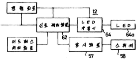
단, 제어터미날장치(14)에 있는 펄스변환회로(53)는 생략되며, 릴레이 구동회로(54)는 광반사 다이오드(64a)용 LED구동회로(64)로 대치되며, 그리고 감시회로(57)는 조광기 스위치(16d) 및 제1도에 도시한 다른 것으로서 여러 가지 스위치(58)로부터 입력에 응하여 입력 데이터신호를 제공하며, 입력 데이터신호는 신호처리회로(62)에 송신되며 감시터미날장치(13)에 있는 개입중단신호(Vi)와 비슷한 데이터신호를 차례로 발생하며, 데이터신호는 중앙제어장치(10)에 송신된다.However, the
각 터미널장치(12, 13 및 14)용 특정 어드레스 설정에 있어서 소망스럽게 8비트 어드레스가 채용되며, 하위 6비트는 사용자에 의해 사용되며, 상위 2비트는 제조자용으로 사용된다.In the specific address setting for each
그러므로 동작, 감시 및 제어터미날장치(12, 13 및 14)용 각 어드레스에서 사용자 사용 비트는 장치 전체를 통해 같은 치를 갖도록 세트되며, 그것에 의해 각 제어터미날장치(14)에 각 동작 및 감시터미날장치(12 및 13)가 대응하도록 설정되며, 반면에 제어터미날장치(14)중 하나에 대응하는 원격제어 릴레이는 같은 비트치의 동작 및 감시터미날장치(12 및 13)중 하나로부터 귀환된 감시데이타에 응하여 구동되며 따라서 소망하는 하나의 부하(15)제어가 실행된다.Therefore, the user use bits at each address for operation, monitoring and control
예를 들어 각 동작 및 감시터미날장치(12 및 13) 및 각 제어터미날장치(14)용 어드레스 데이터의 제1 및 제2비트가 제조자에 의해 "0, 0" 및 "0, 1"로 각각 세트되며, 어드레스 데이터의 제3 내지 제8비트가 사용자에 의해 세트되도록 남겨질 때, 채널(1 내지 63)은 동작 및 감시터미날장치(12 및 13)에 할당되고 채널(128 내지 191)은 제어터미날장치에 할당된다.For example, the first and second bits of the address data for each operation and monitoring
어드레스의 제3 내지 제8 비트 할당에 있어 동작 및 감시터미날장치(12, 13) 및 제어터미날장치(14)사이의 대응은 1:1로 간주된다. 즉 채널에서 0→128, 1→129, …63→191이다.The correspondence between the operation and monitoring
다시 제8도에서, 원격제어 릴레이(23a)는 서로 동작적으로 내부고정된 주 및 보조접점(CON11 및 CON12)을 갖는 래칭 릴레이(PR10), 및 래칭 릴레이(PR10)의 여자코일(L10)과 직렬로 연결된 전류 스위칭 다이오드(D11 및 D12)로 구성되어 제어터미날장치(14)중 하나에 여자가능하도록 연결된다.Again in FIG. 8, the
소정레벨의 세트전류가 변압기(24)(제1도) 및 다이오드(D11)를 통해 전원으로부터 소정기간동안 코일(L10)을 통과할 때, 주접점(CON11)은 상용전원(AC12)으로부터 부하(15)에 전원을 공급하도록 온된다.When the set current of the predetermined level passes through the coil L10 for a predetermined period from the power supply through the transformer 24 (FIG. 1) and the diode D11, the main contact CON11 is loaded from the commercial power supply AC12. 15) to power on.
반면에 보조접점(CON12)은 역으로 동작하여 다이오드(D12)를 코일(L10)에 스위치되도록 연결하며 리세트 전류는 AC전원(AC11)으로부터 다이오드(D12)를 통하여 코일(L10)에 제공된다.On the other hand, the auxiliary contact CON12 operates in reverse to connect the diode D12 to the coil L10 so that the reset current is supplied from the AC power source AC11 to the coil L10 through the diode D12.
주접점(CON11)은 부하에 전류공급을 중단하도록 차단되며 보조접점(CON12)은 다이오드(D11)에 연결된 위치에 역으로 스위치된다.The main contact CON11 is cut off to stop supplying current to the load, and the auxiliary contact CON12 is switched back to the position connected to the diode D11.
제어터미날장치(14)의 릴레이 구동회로(54)에 포함된 광-다이리스터(PS11)가 온될 때 원격제어 릴레이(23a)에 있는 래칭 릴레이(PR10)의 주접점(CON11)은 부하(15)에 전원을 공급하며, 광-다이리스터(PS12)가 온될 때 릴레이(23a)에 있는 래칭 릴레이의 주접점(CON11)은 부하(15)에 전원공급을 중단하도록 차단된다.The main contact CON11 of the latching relay PR10 in the
부분적으로 상술한 것처럼 원격제어 릴레이는 원격제어 스위치(22)에 의해 다른 것과 병렬관계로 제어되도록 제공되며 이 스위치(22)는 제어터미날장치(14)와 대체로 같은 기능을 갖도록 제공된다.As partly described above, the remote control relay is provided to be controlled in parallel with the other by the
제10도에서 원격제어 스위치(22)는 하나 이상의 스위치(SW20) 및 다이오드(D21 및 D22)를 포함하는 세트/리세트 회로(70), 및 광반사 다이오드(LD21 및 LD22)및 각 다이오드(LD21 및 LD22)에 직렬로 각각 연결된 다이오드(D23 및 D24)를 포함하는 온/오프 표시기회로(71)로 구성된다. 따라서 다이오드(D21 또는 D22)와 함께 회로를 구성하여 스위치(SW20)가 디프레스될 때, 세트 또는 리세트 전류가 릴레이(PR10)의 코일(L10)을 여자하도록 공급될 수 있으며 동작은 광반사 다이오드(LD21 또는 LD22)에 의해 표시된다.In FIG. 10, the
다음에 본 발명에 따른 시스템의 동작은 제12도 내지 14도를 참조하여 요약하여 설명된다. 예를들어 제1도의 시스템이 전원에 연결되고 감시 및 제어동작이 시작될 때, 중앙제어장치(10)는 제어터미날장치(14)에 억세스를 초기화하여 장치에 연결된 부하의 제어상태를 확인한다.Next, the operation of the system according to the present invention will be described in summary with reference to FIGS. For example, when the system of FIG. 1 is connected to a power source and monitoring and control operations begin, the
그 다음 입력터미날장치(12)에 순서 억세스가 부하(15)에 대응하는 동작상태에 따른 동작상태를 나타내기 위해 장치(12)에 연결된 각 광반사 다이오드를 온 또는 오프한다. 즉, 만약 임의의 부하상태가 제어패턴 스위치(16c)의 세트패턴에 일치할 경우 각 부하에 대응하는 광반사 다이오드는 켜져 있다.An ordered access to the
중앙제어장치(10)에 있는 신호처리회로(40) 및 다른 것들로 구성되는 더미신호 송신수단은 신호선(11)에 더미 전송신호를 공급하여 각 동작, 감시 및 제어터미날장치(12, 13 및 14)용 특정 어드레스 세트가 아닌 임의의 유휴 어드레스를 억세스한다.The dummy signal transmitting means composed of the
더미 전송신호(Vs)가 끊임없이 제공되는 정상 동작동안 임의의 터미널장치에서 어드레스 일치가 일어나지 않으므로 중앙제어장치(10) 및 각 터미널장치(12, 13 및 14)사이에 데이터 전송이 수행되지 않으며 시스템은 준비상태에 있다.Since no address matching occurs at any terminal device during normal operation in which the dummy transmission signal Vs is constantly provided, no data transmission is performed between the
동작, 감시터미날장치(12 또는 13)의 입력수단에 입력이 일어날 때 또는, 예를들어 독립된 동작 스위치(16a)가 가동되고 대응 터미널장치(12)가 입력을 수신할 때, 동작터미날장치(12)에 신호 처리회로(62)를 포함하는 개입중단신호 발생수단은 개입중단 신호(Vi)를 발생하여 더미 전송신호(Vs)의 시작 펄스신호(ST)와 동기로 신호선(11)에 공급한다.Operation, when an input is made to the input means of the monitoring
중앙제어장치(10)에 있는 개입중단 처리수단이 동작터미날장치(12)로부터 개입중단 신호(Vi)를 수신할 때 중앙제어장치(10)는 개입중단신호를 제공한 것 중의 하나를 검출하도록 터미널장치(12)에 억세스를 수행하며 특정 터미널장치(12)로부터 귀환된 어드레스 데이터신호를 갖기 위해 어드레스 확정 모드신호를 검출된 특정터미날장치(12)에 송신한다.When the interruption interruption processing means in the
어드레스 확정 모드신호를 수신함에 의해 특정 터미널장치(12)에 있는 개입중단신호 발생수단은 더미 전송신호(Vs)의 귀환대기신호(WT)와 동기로 특정 어드레스 데이터를 중앙제어장치(10)에 귀환시킨다. 터미널장치로부터 어드레스 데이터는 중앙제어장치(10)에 있는 개입중단 처리수단에서 수신되며, 개입중단 억세스 모드에 있는 전송신호는 장치(10)로부터 입력이 발생한 입력수단에 있는 특정 터미널장치(12)에 송신된다.By receiving the address determination mode signal, the interruption interruption signal generating means in the specific
특정 터미널장치(12)에 있는 데이터 귀환수단은 수신된 억세스 모드 전송신호에 응답하여 더미 전송신호(Vs)의 귀환대기신호(WT)와 동기로 입력에 대응하는 데이터를 중앙제어장치(10)에 구환한다. 그래서 특정터미날(12)로부터 중앙제어장치(10)에 귀환된 입력데이타는 신호처리회로(40)에 의해 처리되며 따라서 특정터미날장치(12)에 대응하는 부하(15)중의 하나를 제어하기 위한 데이터 및 특정 터미널장치(12)에 대응하는 제어터미날장치(14)중의 하나에 억세스하기 위한 전송신호를 준비한다.The data return means in the specific
수신된 전송신호를 갖는 제어터미날장치(14)는 중앙제어장치(10)에 제어데이타에 기초하여 부하(15)에 대응한 온 또는 오프 제어를 위해 원격제어 릴레이(23a 내지 23n)중의 하나를 제어하며, 부하의 제어상태를 표시하는 데이터를 제어장치(10)에 귀환한다. 제어장치(10)의 순서적 억세스는 대응부하(15)의 동작상태에 따라 그 표시를 갱신하기 위해 부하-동작-표시 광반사 다이오드의 온 및 오프동작을 제어하도록 제어터미날장치(14)로부터 귀환된 데이터에 기초한 터미널장치에 관해 수행되며, 일련의 감시 및 제어동작이 완료된다. 그 이후에 중앙제어장치(10)는 더미 전송신호(Vs)를 계속 전송하는 준비상태로 복귀된다.The
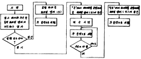
만약 개입중단 신호를 제공한 터미널장치가 임시동작을 실행할 수 있는 것을 경우 중앙제어장치(10)는 터미널장치로부터 입력데이타가 정상모드인지 또는 임시모드인지를 판단한다. 만약 입력데이타가 정상모드일 경우 중앙제어장치(10)는 관련된 제어터미날장치에 온 또는 오프 제어데이타를 송신하며, 만약 임시모드일 경우 장치(10)는 대응 제어터미날장치(14)에 온 제어 데이터를 송신하여 제14도의 흐름도에 도시한 것처럼 시간계수를 시작하며, 소정시간 경과후에 소정시간동안 대응 부하(15)를 여자시키도록 오프 제어 데이터를 장치(14)를 송신하게 한다.If the terminal device providing the interruption stop signal can execute a temporary operation, the
게다가, 중앙제어장치(10)가 양 동작 및 감시터미날장치(12 및 13)로부터 입력을 대체로 동시에 수신할 때, 장치(10)는 감시터미날장치(13)로부터 입력데이타를 우선적으로 먼저 처리하며 이 우선 데이터 처리는 또한 동작터미날장치(12)로부터 입력데이타의 처리동안 감시터미날장치(12)로부터 입력데이타의 처리동안 감시터미날장치(13)로부터 입력데이타의 수신에 따라 처리된다. 동작 및 감시터미날장치로부터 개입중단신호(Vi), 즉 입력터미날장치는 임의의 다른 신호처리에 항상 우선하여 처리되며, 게다가 중앙제어장치(10)는 개입중단신호를 발생하는 임의의 입력터미날장치로부터 입력데이타신호를 신속히 취할 수 있으며, 입력터미날장치의 수가 현저히 증가하는 경우 시스템의 응답을 실질적으로 악화시키지는 않는다. 게다가, 터미널장치에 연결된 광반사 다이오드 수단에 의해 신호 수신상태의 표시, 즉 온 및 오프 표시 또는 신호선용 단락회로 표시가 간단한 표시장치로 만드는 것이 가능하다. 상이한 색을 내는 광반사 다이오드의 부가적인 사용, 즉 온 또는 오프표시를 위한 적 및 녹 광은 시스템의 표시기능을 더욱 향상시킬 수 있다.In addition, when the
부가하여, 본 발명의 원격감시 및 제어시스템은 여러방법으로 수정될 수 있다. 예를들어 중앙제어장치(10)에 있는 신호처리회로(40)는 업계의 숙련가에게 쉽게 식별될 수 있도록, 처리회로의 시스템 프로그램, 입력터미날장치(12, 13) 및 제어터미날(14)사이의 대응 어드레스 관계, 임시 기억데이타 등을 기억하는 메모리 수단과 함께 제공될 수 있다.In addition, the remote monitoring and control system of the present invention can be modified in many ways. For example, the
중앙제어장치(10)에 신호식별을 위해, 클록발생기가 특별히 유리하게 채용되어 시간계수가 제어터미날장치용 제어데이타에 의해 계수된 시간에 따라 효과적으로 제어한다. 또한 동작터미날장치(12)의 신호처리회로(62)가 입력모드 실정회로의 출력을 수신하도록 제공되어 임시 광스위치(16e)의 입력으로부터 개별적인 동작스위치의 입력데이타를 식별하기 위해 입력모드 스위치에 입력이 제공될 때 시스템은 확실하게 개선될 수 있다.For signal identification in the
감시터미날장치(13)는 유선 연결수단이 아닌 무선전송 및 수신수단에 의해 대응 감시입력수단에 동작적으로 연결될 수 있다.The monitoring
게다가 제1도에 도시한 것처럼 부하(15)가 광장비이고 다수의 조광기 스위치(16d)가 동작터미날장치(12)에 있는 감시회로(57)의 입력수단으로써 제공될 때, 시스템은 광장비의 온 및 오프 동작뿐만 아니라 여러 가지 광밀도 제어동작을 실현할 수 있다.In addition, as shown in FIG. 1, when the
이 경우에 상술한 동작터미날장치(12)에 대응하는 제어터미날장치(14)가 3극 진공관 AC 스위치(트라이액) 및 그 트리거링 회로와 함께 제공되며 신호처리회로(62)가 이 트리거링 회로의 시정수 및 트라이액의 위상 제어각을 변화하기 위해 제공될 때 광장비의 광밀도 제어는 위상제어각을 변화함에 의해 소망하는데로 자유롭게 될 수 있으며 여러 가지 조명효과가 실현될 수 있다는 것이 쉽게 이해될 것이다.In this case, a
Claims (4)
Applications Claiming Priority (3)
| Application Number | Priority Date | Filing Date | Title |
|---|---|---|---|
| JP60264206A JPS62123895A (en) | 1985-11-25 | 1985-11-25 | Remote supervisory and controlling equipment |
| JP264206 | 1985-11-25 | ||
| JP60-264206 | 1985-11-25 |
Publications (2)
| Publication Number | Publication Date |
|---|---|
| KR870005285A KR870005285A (en) | 1987-06-05 |
| KR900001032B1 true KR900001032B1 (en) | 1990-02-24 |
Family
ID=17399958
Family Applications (1)
| Application Number | Title | Priority Date | Filing Date |
|---|---|---|---|
| KR1019860009960A KR900001032B1 (en) | 1985-11-25 | 1986-11-25 | Remote supersisory and controlling system |
Country Status (9)
| Country | Link |
|---|---|
| US (1) | US4780872A (en) |
| EP (1) | EP0224300B1 (en) |
| JP (1) | JPS62123895A (en) |
| KR (1) | KR900001032B1 (en) |
| AU (1) | AU585088B2 (en) |
| CA (1) | CA1264187A (en) |
| DE (1) | DE3684884D1 (en) |
| MY (1) | MY100254A (en) |
| PH (1) | PH23680A (en) |
Families Citing this family (19)
| Publication number | Priority date | Publication date | Assignee | Title |
|---|---|---|---|---|
| GB2202076A (en) * | 1987-03-06 | 1988-09-14 | Ibm | Disc file having at least two filters |
| AU593170B2 (en) * | 1987-10-27 | 1990-02-01 | Matsushita Electric Works Ltd. | Remote supervisory and controlling system |
| US5307058A (en) * | 1987-10-27 | 1994-04-26 | Matsushita Electric Works Ltd. | Remote supervisory and controlling system |
| JP2793814B2 (en) * | 1988-09-27 | 1998-09-03 | 松下電工株式会社 | Remote monitoring and control system |
| JP2731585B2 (en) * | 1989-04-25 | 1998-03-25 | 松下電工株式会社 | Remote monitoring and control system |
| MY107353A (en) * | 1989-12-25 | 1995-11-30 | Matsushita Electric Works Ltd | Remote supervisory and controlling system performing dimming control of light loads |
| US5821876A (en) * | 1991-10-08 | 1998-10-13 | Square D Company | Communication interface for bus connected circuit breakers |
| US5340277A (en) * | 1993-05-03 | 1994-08-23 | The Genie Company | Controller for remote control ceiling fan |
| US5635896A (en) * | 1993-12-27 | 1997-06-03 | Honeywell Inc. | Locally powered control system having a remote sensing unit with a two wire connection |
| US6546435B1 (en) * | 1999-06-15 | 2003-04-08 | Matsushita Electric Works, Ltd. | Portable programming device for supervisory remote control system |
| KR100374154B1 (en) * | 2000-06-24 | 2003-02-26 | 장학선 | System for receiving and transmitting power signal and data signal |
| US6664894B2 (en) * | 2001-02-16 | 2003-12-16 | General Phosphorix Llc | Perimeter system for detecting intruders |
| US6832135B2 (en) | 2001-07-10 | 2004-12-14 | Yingco Electronic Inc. | System for remotely controlling energy distribution at local sites |
| US6861956B2 (en) | 2001-07-10 | 2005-03-01 | Yingco Electronic Inc. | Remotely controllable wireless energy control unit |
| US7265652B2 (en) * | 2001-07-10 | 2007-09-04 | Yingco Electronic Inc. | Controllable electronic switch |
| US7324876B2 (en) | 2001-07-10 | 2008-01-29 | Yingco Electronic Inc. | System for remotely controlling energy distribution at local sites |
| US6636141B2 (en) | 2001-07-10 | 2003-10-21 | Yingco Electronic Inc. | Controllable electronic switch |
| US6581846B1 (en) * | 2002-03-06 | 2003-06-24 | Howard B. Rosen | Thermostat including a vacation mode in which electrical devices within and proximate the conditioned space are operated by the thermostat to provide an occupied appearance |
| US9831664B1 (en) * | 2014-05-06 | 2017-11-28 | Google Inc. | Integrated circuit breaker panels |
Family Cites Families (12)
| Publication number | Priority date | Publication date | Assignee | Title |
|---|---|---|---|---|
| AU524953B2 (en) * | 1978-06-21 | 1982-10-14 | Calaby, David Leonard | Parallel tyed cable surveillance system |
| US4429299A (en) * | 1979-01-05 | 1984-01-31 | Robertshaw Controls Company | Two-way AC power line communications system |
| CA1151261A (en) * | 1979-01-05 | 1983-08-02 | Jules M. Kabat | Two-way ac power line communication system |
| AU532683B2 (en) * | 1979-10-30 | 1983-10-06 | General Electric Company | Method and apparatus for controlling distributed electical loads |
| JPS58198994A (en) * | 1982-05-15 | 1983-11-19 | Matsushita Electric Works Ltd | Interruption processing system of time-division multiple remote control system |
| JPS5952992A (en) * | 1982-09-20 | 1984-03-27 | Matsushita Electric Works Ltd | Multiplex transmission control system |
| JPS5980095A (en) * | 1982-10-30 | 1984-05-09 | Matsushita Electric Works Ltd | Remote light dimmer control system |
| SE435010B (en) * | 1982-12-30 | 1984-08-27 | Ellemtel Utvecklings Ab | SET UP AND DEVICE IN A TELECOMMUNICATION SYSTEM FOR ACTIVATION OF BODIES FROM VOLUNTARY TO ACTIVE DOCTOR |
| DE3415008A1 (en) * | 1983-04-27 | 1984-10-31 | Siemens AG, 1000 Berlin und 8000 München | System arrangement for electric signal transmission and signal processing |
| US4628315A (en) * | 1983-08-16 | 1986-12-09 | Sparton Corporation | Addressable transducer with improved address signal processing |
| JPS6072399A (en) * | 1983-09-29 | 1985-04-24 | Toshiba Electric Equip Corp | Remote control device |
| US4644547A (en) * | 1984-06-28 | 1987-02-17 | Westinghouse Electric Corp. | Digital message format for two-way communication and control network |
-
1985
- 1985-11-25 JP JP60264206A patent/JPS62123895A/en active Granted
-
1986
- 1986-11-12 AU AU65053/86A patent/AU585088B2/en not_active Expired
- 1986-11-12 US US06/929,379 patent/US4780872A/en not_active Expired - Lifetime
- 1986-11-14 EP EP86202009A patent/EP0224300B1/en not_active Expired - Lifetime
- 1986-11-14 DE DE8686202009T patent/DE3684884D1/en not_active Expired - Lifetime
- 1986-11-17 MY MYPI86000095A patent/MY100254A/en unknown
- 1986-11-18 CA CA000523267A patent/CA1264187A/en not_active Expired - Lifetime
- 1986-11-21 PH PH34506A patent/PH23680A/en unknown
- 1986-11-25 KR KR1019860009960A patent/KR900001032B1/en not_active IP Right Cessation
Also Published As
| Publication number | Publication date |
|---|---|
| EP0224300A2 (en) | 1987-06-03 |
| EP0224300B1 (en) | 1992-04-15 |
| AU585088B2 (en) | 1989-06-08 |
| DE3684884D1 (en) | 1992-05-21 |
| US4780872A (en) | 1988-10-25 |
| EP0224300A3 (en) | 1989-04-19 |
| JPS62123895A (en) | 1987-06-05 |
| MY100254A (en) | 1990-07-28 |
| PH23680A (en) | 1989-09-27 |
| KR870005285A (en) | 1987-06-05 |
| JPH0361400B2 (en) | 1991-09-19 |
| CA1264187A (en) | 1990-01-02 |
| AU6505386A (en) | 1987-05-28 |
Similar Documents
| Publication | Publication Date | Title |
|---|---|---|
| KR900001032B1 (en) | Remote supersisory and controlling system | |
| AU615405B2 (en) | Power management and automation system | |
| JPH0353840B2 (en) | ||
| US5381078A (en) | Control and communication processor potentiometer system for controlling fluorescent lamps | |
| JPH0434358B2 (en) | ||
| JPH0361399B2 (en) | ||
| JPH0353839B2 (en) | ||
| JPH0428199B2 (en) | ||
| JPH0365079B2 (en) | ||
| JPH04269095A (en) | Multiplex transmission system | |
| JP3488484B2 (en) | Electric shutter system | |
| JP3477220B2 (en) | Operating device for electric shutter system | |
| JPH0695790B2 (en) | Remote monitoring and control device terminals | |
| JP2967877B2 (en) | Lighting control system | |
| JPH0695787B2 (en) | Remote monitoring controller sensor input terminal structure | |
| JPH06299770A (en) | Electric shutter system | |
| JP3449029B2 (en) | Operating device for electric switchgear | |
| JPH0583776A (en) | Wireless receiver for remote control system | |
| JPH0530580A (en) | Terminal equipment for remote control | |
| JPH0695786B2 (en) | Remote monitoring controller | |
| JPH04368728A (en) | Card switch apparatus for remote control system | |
| JPH0431636B2 (en) | ||
| JPH06299771A (en) | Operating device of electric shutter system | |
| JPH08251678A (en) | Remote monitor and control system | |
| JPH0695788B2 (en) | Remote monitoring controller |
Legal Events
| Date | Code | Title | Description |
|---|---|---|---|
| A201 | Request for examination | ||
| G160 | Decision to publish patent application | ||
| E701 | Decision to grant or registration of patent right | ||
| GRNT | Written decision to grant | ||
| FPAY | Annual fee payment |
Payment date: 20060210 Year of fee payment: 17 |
|
| EXPY | Expiration of term |