KR890002171B1 - Cart type conveying apparatus - Google Patents
Cart type conveying apparatus Download PDFInfo
- Publication number
- KR890002171B1 KR890002171B1 KR1019860002838A KR860002838A KR890002171B1 KR 890002171 B1 KR890002171 B1 KR 890002171B1 KR 1019860002838 A KR1019860002838 A KR 1019860002838A KR 860002838 A KR860002838 A KR 860002838A KR 890002171 B1 KR890002171 B1 KR 890002171B1
- Authority
- KR
- South Korea
- Prior art keywords
- vibration
- trolley
- roller
- horizontal extension
- wheel
- Prior art date
Links
Images


Classifications
-
- B—PERFORMING OPERATIONS; TRANSPORTING
- B65—CONVEYING; PACKING; STORING; HANDLING THIN OR FILAMENTARY MATERIAL
- B65G—TRANSPORT OR STORAGE DEVICES, e.g. CONVEYORS FOR LOADING OR TIPPING, SHOP CONVEYOR SYSTEMS OR PNEUMATIC TUBE CONVEYORS
- B65G35/00—Mechanical conveyors not otherwise provided for
-
- B—PERFORMING OPERATIONS; TRANSPORTING
- B61—RAILWAYS
- B61B—RAILWAY SYSTEMS; EQUIPMENT THEREFOR NOT OTHERWISE PROVIDED FOR
- B61B13/00—Other railway systems
- B61B13/04—Monorail systems
-
- B—PERFORMING OPERATIONS; TRANSPORTING
- B61—RAILWAYS
- B61C—LOCOMOTIVES; MOTOR RAILCARS
- B61C13/00—Locomotives or motor railcars characterised by their application to special systems or purposes
- B61C13/04—Locomotives or motor railcars characterised by their application to special systems or purposes for elevated railways with rigid rails
-
- E—FIXED CONSTRUCTIONS
- E01—CONSTRUCTION OF ROADS, RAILWAYS, OR BRIDGES
- E01B—PERMANENT WAY; PERMANENT-WAY TOOLS; MACHINES FOR MAKING RAILWAYS OF ALL KINDS
- E01B25/00—Tracks for special kinds of railways
- E01B25/08—Tracks for mono-rails with centre of gravity of vehicle above the load-bearing rail
-
- E—FIXED CONSTRUCTIONS
- E01—CONSTRUCTION OF ROADS, RAILWAYS, OR BRIDGES
- E01B—PERMANENT WAY; PERMANENT-WAY TOOLS; MACHINES FOR MAKING RAILWAYS OF ALL KINDS
- E01B25/00—Tracks for special kinds of railways
- E01B25/22—Tracks for railways with the vehicle suspended from rigid supporting rails
- E01B25/24—Supporting rails; Auxiliary balancing rails; Supports or connections for rails
-
- Y—GENERAL TAGGING OF NEW TECHNOLOGICAL DEVELOPMENTS; GENERAL TAGGING OF CROSS-SECTIONAL TECHNOLOGIES SPANNING OVER SEVERAL SECTIONS OF THE IPC; TECHNICAL SUBJECTS COVERED BY FORMER USPC CROSS-REFERENCE ART COLLECTIONS [XRACs] AND DIGESTS
- Y02—TECHNOLOGIES OR APPLICATIONS FOR MITIGATION OR ADAPTATION AGAINST CLIMATE CHANGE
- Y02T—CLIMATE CHANGE MITIGATION TECHNOLOGIES RELATED TO TRANSPORTATION
- Y02T30/00—Transportation of goods or passengers via railways, e.g. energy recovery or reducing air resistance
Landscapes
- Engineering & Computer Science (AREA)
- Mechanical Engineering (AREA)
- Transportation (AREA)
- Architecture (AREA)
- Civil Engineering (AREA)
- Structural Engineering (AREA)
- Platform Screen Doors And Railroad Systems (AREA)
- Carriers, Traveling Bodies, And Overhead Traveling Cranes (AREA)
- Framework For Endless Conveyors (AREA)
- Non-Mechanical Conveyors (AREA)
Abstract
Description
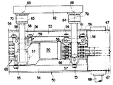
제1도는 종단 정면도.1 is a longitudinal front view.
제2도는 제1도의 주요부의 확대상세도.2 is an enlarged detail view of the main part of FIG.
제2a도는 제2도에서 하부지지용 휘일(A)을 제거한 상태를 도시하고 있는 도면.FIG. 2A is a view showing a state in which the lower support wheel A is removed from FIG.
제2b도는 제2도에서 하부진동방지용 휘일(D)을 제거한 상태를 도시하고 있는 도면.Figure 2b is a view showing a state in which the lower vibration preventing wheel (D) in Figure 2 removed.
제3도는 종단측면도.3 is a longitudinal side view.
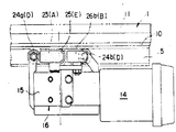
제4도는 구동 트롤리의 일부 절결평면도.4 is a partially cutaway plan view of the drive trolley.
제5도는 종동 트롤리의 일부 절결평면도.5 is a partially cutaway plan view of the driven trolley.
제6도는 다른 실시예를 표시한 종단정면도.6 is a longitudinal sectional front view of another embodiment;
제7도는 종래예의 종단정면도.7 is a longitudinal sectional front view of a conventional example.
제8도는 종래예의 절결측면도.8 is a cutaway side view of a conventional example.
* 도면의 주요부분에 대한 부호의 설명* Explanation of symbols for main parts of the drawings
1 : 가이드레일 2 : 상부 수평연장부1: guide rail 2: upper horizontal extension part
3 : 하부 수평연장부 4, 5 : 안내홈3: lower
13 : 반송대차 4, 5 : 안내홈13:
13 : 반송대차 16, 18 : 트롤리(trolley)13:
A : 하부 지지용휘일 B : 상부 전도방지용 휘일A: Lower support wheel B: Upper fall prevention wheel
D : 하부 진동방지용 로울러 E : 상부 진동방지용 로울러D: Lower anti-vibration roller E: Upper anti-vibration roller
본 발명은 각종 산업분야에 있어서 각종의 피반송물을 미리 정해진 반송경로를 따라서 반송하기 위하여 사용되는 대차식 반송(臺車式搬送)장치에 관한 것이다.BACKGROUND OF THE
대차식 반송장치는 상부 수평연장부와 하부 수평연장부를 갖춘 단면 U자형 비슷한 가이드레일과 그 가이드 레일에 의해 안내되는 트롤리를 갖춘 반송대차가 설치되고 상기 트롤리의 하부위치와 상부위치에 있어서 수평축선상에서 회전할 수 있도록 지지되는 하부 지지용휘일과 상부 전도방지용휘일이 설치되며 또 트롤리의 하부위치와 상부위치에 있어서 수직축선상에서 회전될 수 있도록 지지되는 하부 진동방지용 로울러와 상부 진동방지용 로울러가 설치되게 된다. 또한 상기 반송대차에는 일반적으로 구동트롤리와 종동트롤리가 갖추어져 이들 양 트롤리에 의하여 하대(荷臺)가 지지되던가 또는 매어달리게 되며 또한 각 트롤리의 각각에 상술한 휘일 및 로울러가 설치되게 된다.The trolley conveying device is provided with a conveying bogie with a trolley guided by a U-shaped similar guide rail with a cross-section U-shaped with an upper horizontal extension and a lower horizontal extension, and on a horizontal axis in the lower and upper positions of the trolley. A lower support wheel and an upper fall prevention wheel are installed to be rotatable, and a lower anti-vibration roller and an upper anti-vibration roller are supported to be rotated on the vertical axis at the lower and upper positions of the trolley. . In addition, the transport trolley is generally equipped with a drive trolley and a driven trolley, the lower base is supported or suspended by both of these trolleys, and the wheels and rollers described above are installed on each of the trolleys.
종래 이런 종류의 반송제어장치에서는 제7도 및 제8도에 표시한 바와같이 가이드레일(50)에 있어서의 상부 수평연장부(51)의 하부위치와 하부 수평연장부(52)의 상부위치에 안내용의 돌출부(53, 54)가 형성되고 하부 진동방지용로울러(55) 및 상부진동방지용로울러(56)의 각각이 상기 돌출부(53, 54)를 좌우 양측에서 에워싸는 것과같이 배설되고 지지용휘일(57)이 하부수평연장부(52)의 돌출부(54)의 상면에 놓여지도록 배치되며 전도방지용휘일(58)이 상부 수평연장부(51)의 돌출부(53)의 하면에 접촉하도록 배치되어 있다.In the conventional conveyance control apparatus of this type, as shown in FIGS. 7 and 8, the lower position of the upper horizontal extension portion 51 and the upper position of the lower
다만 도면속에 있어서 59는 전도모우터(60)를 갖춘 구동트롤리, 61은 종동크롤리, 62는 하대, 63, 64는 상기 각 트롤리(59, 61)로부터 뻗어나온 하대지지아암, 65는 전력공급 및 신호송수신용의 레일유니트, 66은 콜렉터유니트, 67은 상하 1쌍의 레일커버, 68은 가이드레일 지지용 스탠드이다.However, in the drawings, 59 is a drive trolley having a
또한 상기 하대(62)와 상기 양 지지아암(63, 64)들은 수직축선(69)상에서의 회전운동 및 수평축선(70)상에서의 회전운동을 할 수 있도록 피봇식으로 상호 연결되어서 가로곡선이나 세로곡선에서의 주행을 원활하게 할 수 있도록 되어있다.In addition, the
이때문에 각 트롤리(59, 61) 각각에는 하부 지지용휘일(57)이 1개 설치되는데 대하여 상부 전도방지용 휘일(58)이 전후 1쌍 설치되며, 또 하부 진동방지용로울러(55)가 전후방향 한위치 설치되는데 대하여 상부 진동방지용 로울러(56)가 전후방향 두위치에 설치되어 있다.For this reason, each of the
즉, 하대(62)와 각 지지아암(63, 64)이 강체(剛體) 연결되는 경우에는 상부 전도방지용 로울러(58)가 1개로 족하며 또 상부 진동방지용로울러(56)도 전후방향 한위치로 족하게 되나 구동트롤리(59) 및 종동트롤리(61) 각각의 자세를 그 자체로서 규제할 수 있게 하는데는 상술한 바와같이 상부 전도방지용휘일(58)이 전후 1쌍 설치되고 상부 진동방지용 로울러(56)가 전후방향 두위치에 설치되게 된다.That is, when the
이와 관련하여 하부 지지용휘일(57)이 전후 1쌍 설치되고 상부 전도방지용휘일(58)이 1개 설치되며 또 하부 진동방지용로울러(55)가 전후방향 한위치에 설치되도록 하여도 구동트롤리(59) 및 종동틀로리(61)의 각각의 자세를 그 자체로써 규제할 수도 있다고는 하여도 큰 하중이 작용하는 지지용휘일(57)을 큰 직경으로 하는 것이 요망되기 때문에 일반적으로 1개의 하부지지용휘일(57)이 설치될때가 많다. 다만, 진동방지용로울러(55, 56)는 하부 및 상부의 어느쪽도 전후방향 두위치에 설치하도록 하여도 좋다.In this connection, the
상기와 같은 종래의 대차식 반송장치에 의하면 하부 진동방지용로울러(55) 및 상부 진동방지용로울러(56)의 각각이 상기 돌출부(53, 54)의 양쪽에 배설되는 것이기 때문에 하부 지지용 휘일(57)이 구름운동하는 돌출부(54)의 양측면이나 상부 전동방지용휘일(58)이 구름운동하는 돌출부(53)의 양측면에 진동방지용로울러(55, 56)의 구름운동공간이 필요하게 된다. 그리고 가이드레일(50)의 바깥쪽에 위치시키는 진동방지용로울러(55, 56)의 구름운동공간을 확보하는 것은 큰 불리없이 할 수 있는 것이나 가이드레일(50)의 안쪽에 위치시키는 진동방지용로울러(55, 56)의 구름운동공간을 확보하기 위하여는 하부 수평연장부(52)와 상부 수평연장부(51)의 길이를 크게 하지 않으면 안되며, 그 결과 가이드레일(50)을 형성하기 위한 재료가 많아져서 제작원가가 비싸게 되는 불리한 점이나, 가이드레일(50)의 중량이 무거워져 설치작업이 곤란하게 되는 불리한 점이 있다.According to the conventional trolley conveying apparatus as described above, since each of the lower
또 하부 진동방지용로울러(55) 및 상부 진동방지용로울러(56)의 각각은 돌출부(53, 54)의 양측면에 설치되므로써 진동방지작용을 발휘하는 것이기 때문에, 진동방지용로울러(55, 56)의 설치수가 많아져서, 그 결과 부품수효의 증대에 따른 조립작업이 번잡하게 되는 결점이 있을 뿐만 아니라, 제작원가의 상승이나 트롤리(59, 61)의 중량증대를 생기게 하는 결점이 있다.In addition, since each of the lower
또한 상술한 바와같이 각 트로리(59, 61)의 각각의 자세를 그 자체로써 규제할 경우에 있어서는 돌출부(53, 54)의 양측면에 진동방지용로울러(55, 56)를 위치시키므로써 각 트롤리(59, 61)의 각각에 진동방지용로울러(55, 56)를 6개나 설치하지 않으면 안되게 한다.In addition, as described above, in the case of regulating the posture of each of the
본 발명의 목적은 가이드레일을 형성하기 위한 재료의 절감 및 가이드레일의 경량화를 도모하며 또한 진동 방지용로울러의 설치수효를 감소시키는 점에 있다.An object of the present invention is to reduce the material for forming the guide rail and to reduce the weight of the guide rail and to reduce the number of installation of the anti-vibration roller.
본 발명의 다른 목적은 상기 목적에 더하여 트롤리의 자세를 그 자체로써 규제할 수 있도록 하면서도 트롤리의 전후길이를 갖게하는 점에 있다.Another object of the present invention is to provide a front and rear length of the trolley while allowing the trolley posture to be regulated by itself in addition to the above object.
이러한 목적달성을 위하여, 본 발명에 따른 대차식 반송장치는, 상부 수평연장부의 하부위치와 하부 수평 연장부의 상부위치에 안내홈이 형성되어 있고, 상부 전도방지용휘일이 상부 수평연장부의 안내홈안의 수평부와 구름접촉상태로 설치되어 있고 상부진동방지용로울러가 상기 안내홈에 수직벽부와의 구름접촉상태로 삽입 설치되어 있으며, 하부 지지용휘일이 하부 수평연장부의 안내홈안의 수평부의 위에 구름접촉상태로 설치되어 있고, 하부 진동방지용로울러가 상기 안내홈에 수직벽부와의 구름접촉상태로 삽입 설치되어 있는 것을 특징으로 하고 있으며, 그것에 의한 작용·효과는 다음과 같다.In order to achieve this object, the trolley conveying apparatus according to the present invention, the guide groove is formed in the lower position of the upper horizontal extension and the upper position of the lower horizontal extension, the upper fall prevention wheel is horizontal in the guide groove of the upper horizontal extension The upper vibration prevention roller is inserted into the guide groove in the rolling contact state with the vertical wall part, and the lower support wheel is in the cloud contact state on the horizontal part in the guide groove of the lower horizontal extension part. And a lower vibration preventing roller is inserted into the guide groove in a rolling contact with the vertical wall portion, and the action and effect thereof are as follows.
먼저 작용에 대하여 설명한다.First, the operation will be described.
즉 하부 진동방지용로울러 및 상부 진동방지용로울러의 각각은 안내홈의 좌우의 수직벽부와의 구름접촉에 의하여 진동방지작용을 발휘하게 되며, 지지용휘일은 하부 수평연장부의 안내홈의 수평부의 위에 구름접촉상태로 놓이며 또 전도방지용휘일은 상부 수평연장부의 안내홈의 수평부와 구름접촉하게 된다.That is, each of the lower anti-vibration rollers and the upper anti-vibration rollers exerts anti-vibration action by rolling contact with the vertical wall portions on the left and right of the guide groove, and the support wheel is a cloud on the horizontal part of the guide groove of the lower horizontal extension. It is placed in contact and the fall prevention wheel is brought into contact with the horizontal part of the guide groove of the upper horizontal extension part.
본 발명의 효과는 다음과 같다.The effects of the present invention are as follows.
따라서, 가이드레일의 길이방향에 있어서, 지지용휘일이나 전도방지용휘일의 배설공간을 진동방지용로울러의 배설공간으로 겸용할 수 있으므로 가이드레일의 하부 수평연장부와 상부 수평연장부의 길이를 작게 할 수가 있으며, 그 결과 가이드레일을 형성하기 위한 재료가 적게들어서 제작원가가 절감되는 이점과 가이드레일의 중량이 가벼워져서 설치작업을 하기 쉽게되는 이점이 있다.Therefore, in the longitudinal direction of the guide rail, the excrement space of the support or fall prevention wheel can be used as the excretion space of the anti-vibration roller, so the length of the lower horizontal extension portion and the upper horizontal extension portion of the guide rail can be reduced. As a result, there is an advantage that the production cost is reduced by using less material for forming the guide rail and the weight of the guide rail is lighter, so that the installation work is easier.
또 하부 진동방지용로울러 및 상부 진동방지용로울러의 각각은 그것만으로서 진동방지작용을 발휘하는 것이기 때문에 진동방지용로울러의 설치수효를 적게 할 수가 있어서, 그 결과 부품수효의 감소에 따른 조립작업의 용이화를 도모할 수 있는 이점이 있을 뿐만 아니라, 제작원가의 절감 및 트롤리의 중량감소를 도모할 수 있는 이점이 있다.In addition, since each of the lower anti-vibration rollers and the upper anti-vibration rollers exerts an anti-vibration effect by itself, the number of installation of the anti-vibration rollers can be reduced, thereby consequently facilitating the assembly work by reducing the number of parts. Not only can there be advantages, but also there is an advantage that can reduce the manufacturing cost and weight of the trolley.
본 발명에 관한 대차식 반송장치의 바람직한 실시의 모양은 다음과 같다.The form of the preferable implementation of the trolley | bogie conveyance apparatus which concerns on this invention is as follows.
상기 지지용휘일이 1개 설치되어 있고, 상기 전도방지용휘일이 전후 1쌍 설치되어 있으며, 상기 하부 진동 방지용로울러가 상기 지지용휘일의 전방위치와 후방위치에 배치되어 있고, 상기 상부 진동방지용로울러가 상기 전후 1쌍의 전도방지용 휘일의 사이에 배치되어 있다.The support wheel is provided, the fall prevention wheel is provided in front and rear pairs, the lower vibration prevention rollers are disposed at the front position and the rear position of the support wheel, and the upper vibration prevention roller It is arrange | positioned between the said front and back pair of fall prevention wheels.
이 실시의 모양에 의하면, 트롤리의 하부위치에 1개의 지지용휘일과 2개의 진동방지용로울러를 전후방향으로 늘어놓고 트롤리의 상부위치에 2개의 전도방지용휘일과 1개의 진동방지용로울러를 전후방향으로 늘어놓고 트롤리의 자세를 그 자체로써 규제할 수 있도록 하는 것이기 때문에, 예컨대 트롤리의 하부위치에 1개의 지지용 휘일과 1개의 진동방정용로울러를 늘어놓고 트롤리의 상부위치에 2개의 전도방지용로울러와 2개의 진동방지용로울러를 전후방향으로 늘어놓도록 하는데 비하여 트롤리의 전후길이를 작게할 수 있다.According to this embodiment, one supporting wheel and two anti-vibration rollers are arranged in the front and rear directions at the lower position of the trolley, and the two anti-vibration wheels and one anti-vibration roller are arranged in the front and rear direction at the upper position of the trolley. The position of the trolley itself can be adjusted by itself, so for example, one supporting wheel and one vibration measuring roller are arranged in the lower position of the trolley and two anti-rolling rollers and two The front and rear length of the trolley can be made smaller than the vibration preventing rollers are arranged in the front and rear directions.
본 발명의 기타의 이점은 이하의 설명에서 분명하게 될 것이다.Other advantages of the present invention will become apparent from the following description.
제1도 내지 제5도는 대차식반송장치의 실시예를 표시한 것이다.1 to 5 show an embodiment of the balance type conveying apparatus.
1은 상부 및 하부 수평연장부(2, 3)를 갖춘 단면 U자형 비슷한 가이드레일로서 제2도에 단면형상이 상세하게 표시되어 있는 바와같이 상부 수평연장부(2)의 하부위치와 하부 수평연장부(3)의 상부위치에 안내홈(4, 5)이 형성되어 있고 상기 상부 수평연장부(2)의 상부 양옆끝위치 및 상기 하부수평연장부(3)의 하부 양옆끝위치에 볼트너트 고착용의 레이스(6a, 6b, 7a, 7b)가 형성되어 있으며 다시 상기 상부 및 하부수평연장부(2, 3)의 기초부에는 서로 대향하는 돌출부(8a, 8b)가 돌출설치되어 있다. 9는 상하 복수단의 통전레일(10)로부터 이루어진 전력공급 및 신호송수신용 레일유니트이며, 상기 가이드레일(1)의 수직벽부(11)에 인접하는 위치에 길이방향의 적당한 간격으로 배치된 통전레일지지구(12)에 지지되어 있다.1 is a U-shaped similar guide rail having a U-shaped cross section with upper and lower
상기 통전레일지지구(12)는 그 상하 양끝부분이 상기 돌출부(8a, 8b)에 끼워맞춤 고정되어 있다.The upper and lower ends of the energizing
13은 반송대차로서 모우터(14)를 직결한 감속기(15)로 트롤리본체를 겸용시킨 구동틀로리(16), 전후양쪽에 콜렉터유니트(17a, 17b)를 부착한 종동트롤리(18) 및 하대(19)로 구성되어 있다.13 is a
상기 하대(19)는 가이드레일(1)의 바로위에 배치되는 것으로서 구동트롤리(16) 및 종동틀로리(18)의 바깥쪽 면(가이드레일)(1)에 인접하는 쪽과는 반대쪽)에 하단을 붙이고 떼기가 자유롭게 부착된 전후 1쌍의 하대 지지아암(20, 21)의 상단에 상기 가이드레일(1)의 안내홈(4, 5)의 바로위에 위치하는 수직축(22)(제1도참조)의 주위에서 회전이 자유롭게 결합되어 있다.The
상기 트롤리(16, 18)는 그 하부위치와 상부위치에 있어서 수평축선상에서 회전할 수 있도록 지지된 하부 지지용휘일(A)과 상부 전도방지용휘일(B)을 갖춤과 동시에 그 하부위치와 상부위치에 있어서 수직축선상에서 회전할 수 있도록 지지된 하부 진동방지용로울러(D)와 상부 진동방지용로울러(E)를 갖추고 있는 것이며 다음에 각 트롤리(16, 18)에 대하여 구체적으로 설명한다. 다만 각 트롤리(16, 18)의 각각의 구성을 이해하기 쉽게 하기 위하여 이하의 설명에 있어서는 상기 휘일(A, B)이나 상기 로울러(D, E)를 설명할 때에 다른 부호를 부기한다.The
상기 구동트롤리(16)는 상기 감속기(15)의 수평횡방향 출력축에 부착되어서 구동됨과 동시에 상기 가이드레일(1)의 하부안내홈(5)안의 수평부(5b)의 위에 구름접촉상태로 놓여있는 1개의 지지용휘일(23), 휘일(23)의 전후에 있어서 상기 하부안내홈(5)에 수직벽부(5a)와의 구름접촉상태로 삽입되어 있는 전후 1쌍의 진동방지용로울러(24a, 24b), 상기 휘일(23)의 바로위에 배치됨과 동시에 상기 가이드레일(1)의 상부 안내홈(4)에 수직벽부(4a)와의 구름접촉상태로 삽입되어 있는 1개의 진동방지용로울러(25) 및 이 로울러(25)의 전후에 있어서 상기 상부안내홈(4)안의 수평부(4b)와 구름접촉하는 전후 1쌍의 전도방지용휘일(26a, 26b)을 갖추고 있다.The
구동트롤리(16)는 이들 휘일(23, 26a, 26b) 및 로울러(24a, 24b, 25)에 의해서 가이드레일(1)의 바로 옆의 바깥쪽으로 돌출하는 상태로 지지되어 있다.The
상기 종동트롤리(18)는 상기 가이드레일(1)의 하부안내홈(5)안의 수평부(5b)의 위에 구름접촉상태로 놓여 있는 1개의 지지용휘일(27), 이 휘일(27)의 전후에 있어서 상기 하부안내홈(5)에 수직벽부(5a)와의 구름접촉 상태로 삽입되어 있는 로울러(28a, 28b), 상기 휘일(27)의 바로위에 배치됨과 동시에 상기 가이드레일(1)의 상부 안내홈(4)에 수직벽부(4a)와의 구름접촉 상태로 삽입되어 있는 1개의 진동방지용 로울러(29) 및 이 로울러(29)의 전후에 있어서 상기 상부 안내홈(4)안의 수평부(4b)와 구름접촉하는 전후 1쌍의 전도방지용휘일(30a, 30b)을 갖추고 있다.The driven
종동트롤리(18)는 구동트롤리(16)와 마찬가지로 이들 휘일(27, 30a, 30b) 및 로울러(28a, 28b, 29)에 의해서 가이드레일(1)의 바로평의 바깥쪽으로 돌출하는 상태로 지지되어 있다.The driven
상기 콜렉터유니트(17a, 17b)는 제3도 및 제5도에 표시된 바와같이, 각단의 통전레일(10)과 미끄럼 접촉하는 상하 복수단의 집전자(集電子)(31a, 31b)를 갖추고 동일한 통전레일(10)과 미끄럼 접촉하는 1쌍의 집전자(31a, 31b)는 대응하는 전기적으로 서로 접속되어 있고 또한 각 집전자(31a, 31b)는 통전레일(10)의 위치가 상하로 약간 어긋나 있어도 이 통전레일(10)에 대하여 압점(壓接)하면서 원활하게 미끄럼접촉 이동하도록 탄성적으로 지지되어 있으며, 종래 주지의 것과 기본구성에 있어서는 동일하나 본 실시예에서의 특징은 양 콜렉터유니트(17a, 17b)를 종동트롤리(18)의 전후에 분할 배치하여 양 콜렉터유니트(17a, 17b)의 중간에 종동트롤리(18)에 설치되는 휘일(27, 30a, 30b)및 로울러(28a, 28b, 29)를 배치하고 가이드레일(1)과 반송대차(13)를 포함한 반송장치 전체의 가로폭과 반송대차(13)의 전체길이를 최소한으로 억제할 수 있도록 한 점에 있다.The
32a, 32b는 상하 1쌍의 레일커버로서 가이드레일(1)의 상부레이스(6b)와 하부레이스(7b)에 볼트너트(33)를 개재시켜 부착된다. 또, 34는 가이드레일 지주로서 가이드레일(1)의 하부레이스(7a, 7b)를 이용하여 길이방향 임의의 위치에 볼트너트(35)에 의하여 부착할 수가 있다.32a and 32b are a pair of upper and lower rail covers which are attached to the
상기와 같이 구성된 대차식 반송장치에 의하면 전력공급 및 신호송수신용 레일유니트(9)의 통전레일(10)로 부터 콜렉터유니트(17a, 17b)의 집전자(31a, 31b)를 경유하여 반송대차(13)에 공급되는 전력과 제어신호에 의해서 모우터(14)를 가동시켜 구동트롤리(16)의 지지용휘일(23)을 회전시켜서 구동트롤리(16)를 추진시킴으로써 반송대차(13)를 가이드레일(1)을 따라 전진 또는 후진이동시킬 수가 있다.According to the bogie conveying apparatus configured as described above, the conveyance bogie (via the current collectors 31a, 31b of the
이 반송대차(13)의 이동에 있어서, 측면에서 볼 때 구동트롤리(16) 및 종동트롤리(18)가 전후로 기울어지는 것은 수평축선상에서 회전가능한 각각 전후 1쌍의 전후 전도방지용휘일(26a, 26b, 30a, 30b)에 의해서 방지되며, 또한 수직축선상에서 회전가능한 각각 3개의 진동방지용로울러(24a, 24b, 25, 28a, 28b, 29)에 의해서 평면으로 볼때 가이드레일(1)과 평행한 자세로 유지된다. 또한 가이드레일(1)이 수직방향으로도 만곡하는 부분을 가진 경우에는 하대 지지아암(20, 21)과 하대(19)와의 결합부에 수평횡축주위의 상대회전부를 개재시킴과 동시에 콜렉터유니트(17a, 17b)를 종동트롤리(18)에 대하여 각각 따로 상하방향으로 요동가능하게 구성하면 된다.In the movement of the
다음에 다른 실시예를 설명한다.Next, another embodiment will be described.
제6도에 표시한 바와같이 구동트롤리(16)과 종동트롤리(18)의 하부면에 붙이고 떼기가 자유롭게 부착된 하대현수용아암(36)을 이용하여 하대를 매어달 수도 있다.As shown in FIG. 6, the lower platform may be suspended by using the
이 경우 상부레이스(6a, 6b)를 이용하여 가이드레일(1)의 길이방향 임의의 위치에 볼트너트로 부착한 현수간(38)에 의하여 이 가이드레일(1)을 매어달아서 가설할 수가 있다.In this case, the
가이드레일(1)의 상하 양쪽에 설치된 볼트너트 고착용레이스(6a, 6b, 7a, 7b)는 일정한 길이의 가이드레일(1)을 접속할 경우, 접속판의 양단을 양쪽의 가이드레일(1)의 상하 양쪽에 고정할때에도 활용할 수 있다.The bolt
Claims (3)
Applications Claiming Priority (9)
| Application Number | Priority Date | Filing Date | Title |
|---|---|---|---|
| JP81771 | 1985-04-17 | ||
| JP60-57262 | 1985-04-17 | ||
| JP60081771A JPS61241257A (en) | 1985-04-17 | 1985-04-17 | Truck type conveyor |
| JP57262 | 1985-04-17 | ||
| JP57263 | 1985-04-17 | ||
| JP60-57263 | 1985-04-17 | ||
| JP1985057263U JPH0415767Y2 (en) | 1985-04-17 | 1985-04-17 | |
| JP60-81771 | 1985-04-17 | ||
| JP5726285U JPH0423732Y2 (en) | 1985-04-17 | 1985-04-17 |
Publications (2)
| Publication Number | Publication Date |
|---|---|
| KR860008078A KR860008078A (en) | 1986-11-12 |
| KR890002171B1 true KR890002171B1 (en) | 1989-06-22 |
Family
ID=27296193
Family Applications (1)
| Application Number | Title | Priority Date | Filing Date |
|---|---|---|---|
| KR1019860002838A KR890002171B1 (en) | 1985-04-17 | 1986-04-14 | Cart type conveying apparatus |
Country Status (6)
| Country | Link |
|---|---|
| US (1) | US4671183A (en) |
| KR (1) | KR890002171B1 (en) |
| CA (1) | CA1231664A (en) |
| DE (1) | DE3612500A1 (en) |
| FR (1) | FR2580571B1 (en) |
| GB (1) | GB2175555B (en) |
Families Citing this family (26)
| Publication number | Priority date | Publication date | Assignee | Title |
|---|---|---|---|---|
| CH673666A5 (en) * | 1987-01-20 | 1990-03-30 | Von Roll Transportsysteme | |
| US4776282A (en) * | 1987-03-10 | 1988-10-11 | Tsubakimoto Chain Company | Self-running device for a transporting carrier |
| GB2214146B (en) * | 1987-12-26 | 1991-11-20 | Daifuku Kk | "conveyor trolley" |
| DE3800162A1 (en) * | 1988-01-07 | 1989-07-20 | Systemtechnik Gmbh | Monorail |
| DE4008196A1 (en) * | 1988-10-11 | 1991-09-19 | Rixen Wolfgang | Rail type conveyor for workpieces - has inward facing current rails on each drive rail, coacting with pick=ups |
| DE3903949A1 (en) * | 1989-02-10 | 1990-08-16 | Wampfler Gmbh | TRANSPORT DEVICE |
| JP2509486Y2 (en) * | 1989-07-31 | 1996-09-04 | 中西金属工業株式会社 | Carrier self-propelled conveyor |
| US5074220A (en) * | 1989-08-07 | 1991-12-24 | Stanley Petersen | Overhead monorail transit system employing carriage with upper guide wheel and guideway with concave upper surface |
| ES2048067B1 (en) * | 1990-10-15 | 1997-07-01 | Daifuku Kk | MONO-RAIL WAGON TYPE CONVEYOR. |
| DE4033373C2 (en) * | 1990-10-18 | 1996-04-25 | Mannesmann Ag | Trolley |
| DE9200854U1 (en) * | 1992-01-25 | 1993-05-27 | Rixen, Wolfgang, Dipl.-Ing. | |
| DE9206405U1 (en) * | 1992-05-12 | 1992-07-23 | Nadella-Waelzlager Gmbh, 7000 Stuttgart, De | |
| US5456183A (en) * | 1992-12-09 | 1995-10-10 | Geldbaugh; G. Richard | Integrated infrastructure transit system |
| US5492066A (en) * | 1993-07-30 | 1996-02-20 | Shinko Electric Co., Ltd. | Transport system |
| US5664503A (en) * | 1994-07-27 | 1997-09-09 | Shinko Electric Co., Ltd. | Container for linear motor driven transport system |
| US5662045A (en) * | 1995-09-06 | 1997-09-02 | Symorex, Ltd. | Locomotive for material handling train |
| US7559282B2 (en) * | 2002-10-16 | 2009-07-14 | Robert Austin | Monorail sortation system |
| US8776694B2 (en) | 2002-10-16 | 2014-07-15 | Cross Belt Ip, Llc | Monorail sortation system |
| US9102336B2 (en) | 2002-10-16 | 2015-08-11 | Cross Belt Ip, L.L.C. | Portable bin for sortation system |
| EP1413541A1 (en) * | 2002-10-22 | 2004-04-28 | BC Lift A/S | Guide rail for a stairlift |
| US7684034B2 (en) * | 2007-05-24 | 2010-03-23 | Applied Vision Company, Llc | Apparatus and methods for container inspection |
| CN102673963B (en) * | 2012-05-08 | 2015-01-07 | 杭州恒农科技股份有限公司 | Mobile seedling bed conveying automatic correcting device and method |
| CN106429280B (en) * | 2016-11-03 | 2019-01-04 | 湖北三丰智能输送装备股份有限公司 | A kind of automobile Workpiece coating production line |
| US10569764B2 (en) * | 2018-06-14 | 2020-02-25 | Zdenek Stan Emil Skokan | Apparatus and method for energy and space efficient transportation system |
| JP7147735B2 (en) * | 2019-12-02 | 2022-10-05 | 株式会社ダイフク | Running rails and goods transport equipment |
| CN111663379B (en) * | 2020-06-08 | 2021-07-23 | 中国五冶集团有限公司 | Track beam mounting device and mounting method thereof |
Family Cites Families (9)
| Publication number | Priority date | Publication date | Assignee | Title |
|---|---|---|---|---|
| US3086482A (en) * | 1960-11-25 | 1963-04-23 | Walker Mfg Co | Trolley |
| US3194179A (en) * | 1963-08-09 | 1965-07-13 | Lester G Scherer | Monorail system |
| US3604434A (en) * | 1969-03-21 | 1971-09-14 | Malsbary Mfg Co | Automatic carwash apparatus |
| US3845723A (en) * | 1971-12-28 | 1974-11-05 | J Jacobs | Highly improved transportation system |
| DE2303515A1 (en) * | 1972-01-18 | 1974-08-01 | Krauss Maffei Ag | ROAD ELEMENT FOR A MAGNETICALLY GUIDED HOVER VEHICLE |
| NL7309737A (en) * | 1972-07-25 | 1974-01-29 | ||
| US3942450A (en) * | 1974-04-05 | 1976-03-09 | Carlos Bordons Elorza | Overhead transportation system |
| CH597426A5 (en) * | 1974-10-17 | 1978-04-14 | Blaser Hebe Foerderanlagen | |
| US4531460A (en) * | 1982-03-10 | 1985-07-30 | Litton Systems, Inc. | Material handling system |
-
1986
- 1986-04-03 GB GB08608153A patent/GB2175555B/en not_active Expired
- 1986-04-10 US US06/850,153 patent/US4671183A/en not_active Expired - Lifetime
- 1986-04-14 KR KR1019860002838A patent/KR890002171B1/en not_active IP Right Cessation
- 1986-04-14 DE DE19863612500 patent/DE3612500A1/en active Granted
- 1986-04-16 CA CA000506828A patent/CA1231664A/en not_active Expired
- 1986-04-17 FR FR8605513A patent/FR2580571B1/en not_active Expired - Lifetime
Also Published As
| Publication number | Publication date |
|---|---|
| FR2580571A1 (en) | 1986-10-24 |
| FR2580571B1 (en) | 1994-05-27 |
| GB8608153D0 (en) | 1986-05-08 |
| DE3612500A1 (en) | 1986-10-30 |
| KR860008078A (en) | 1986-11-12 |
| GB2175555B (en) | 1989-02-01 |
| DE3612500C2 (en) | 1988-09-29 |
| GB2175555A (en) | 1986-12-03 |
| CA1231664A (en) | 1988-01-19 |
| US4671183A (en) | 1987-06-09 |
Similar Documents
| Publication | Publication Date | Title |
|---|---|---|
| KR890002171B1 (en) | Cart type conveying apparatus | |
| SU1616511A3 (en) | Installation for sorting parts | |
| US2593699A (en) | Booster conveyer for gravity conveyer systems | |
| JP2909552B2 (en) | Self-propelled trolley and support track structure | |
| KR950002937B1 (en) | Monorail tramcar type conveyor | |
| ES2097563T3 (en) | TRANSPORT UNIT OF A CONVEYOR FACILITY AT THE HEIGHT OF THE GROUND. | |
| CN213010364U (en) | Power supply communication device for sorting machine and sorting machine | |
| JP2772928B2 (en) | Transport equipment using carts | |
| JP2741200B2 (en) | Load transfer device | |
| CN113171989A (en) | High-speed linear crossed belt sorting equipment and working method thereof | |
| GB1105608A (en) | Improvements in or relating to conveyors for conveying goods | |
| JPH0415767Y2 (en) | ||
| EP0520475A1 (en) | Geared motor for self-traveling carrier | |
| JP2689775B2 (en) | Load transfer device | |
| JP2748730B2 (en) | Rail support device for load transfer device | |
| JPH0872709A (en) | Traveling wheel supporting device for transportation device | |
| JPH0423732Y2 (en) | ||
| CN220315164U (en) | Ground trolley | |
| JP2751674B2 (en) | Load transfer device | |
| JPH0323390B2 (en) | ||
| JPH0532317A (en) | Load transporting device | |
| JPS616063A (en) | Conveyor utilizing electric travelling truck | |
| JPH02291381A (en) | Transfer device | |
| JPH0721452Y2 (en) | Sorting device | |
| JP2004277017A (en) | Mechanical type transportation device |
Legal Events
| Date | Code | Title | Description |
|---|---|---|---|
| A201 | Request for examination | ||
| E902 | Notification of reason for refusal | ||
| G160 | Decision to publish patent application | ||
| E701 | Decision to grant or registration of patent right | ||
| GRNT | Written decision to grant | ||
| FPAY | Annual fee payment |
Payment date: 20050614 Year of fee payment: 17 |
|
| EXPY | Expiration of term |