KR880000615B1 - Supplying apparatus of materials to press - Google Patents
Supplying apparatus of materials to press Download PDFInfo
- Publication number
- KR880000615B1 KR880000615B1 KR1019840001185A KR840001185A KR880000615B1 KR 880000615 B1 KR880000615 B1 KR 880000615B1 KR 1019840001185 A KR1019840001185 A KR 1019840001185A KR 840001185 A KR840001185 A KR 840001185A KR 880000615 B1 KR880000615 B1 KR 880000615B1
- Authority
- KR
- South Korea
- Prior art keywords
- arm
- processing material
- press
- lever
- carrying arm
- Prior art date
Links
Images


Classifications
-
- B—PERFORMING OPERATIONS; TRANSPORTING
- B21—MECHANICAL METAL-WORKING WITHOUT ESSENTIALLY REMOVING MATERIAL; PUNCHING METAL
- B21D—WORKING OR PROCESSING OF SHEET METAL OR METAL TUBES, RODS OR PROFILES WITHOUT ESSENTIALLY REMOVING MATERIAL; PUNCHING METAL
- B21D43/00—Feeding, positioning or storing devices combined with, or arranged in, or specially adapted for use in connection with, apparatus for working or processing sheet metal, metal tubes or metal profiles; Associations therewith of cutting devices
- B21D43/02—Advancing work in relation to the stroke of the die or tool
- B21D43/04—Advancing work in relation to the stroke of the die or tool by means in mechanical engagement with the work
- B21D43/05—Advancing work in relation to the stroke of the die or tool by means in mechanical engagement with the work specially adapted for multi-stage presses
-
- B—PERFORMING OPERATIONS; TRANSPORTING
- B30—PRESSES
- B30B—PRESSES IN GENERAL
- B30B15/00—Details of, or accessories for, presses; Auxiliary measures in connection with pressing
- B30B15/30—Feeding material to presses
Abstract
Description
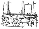
제1도는 본 발명의 1실시예를 나타낸 프레스기와 송급 장치의 정면도.1 is a front view of the press and the feeding device showing an embodiment of the present invention.
제2도는 제1도에 나타낸 프레스기와 송급 장치의 평면도.2 is a plan view of the press and the feeding device shown in FIG.
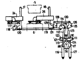
제3도는 제1도에 나타낸 송급 장치의 동력 전달 기구의 정면에서 본 단면도.3 is a sectional view seen from the front of the power transmission mechanism of the power supply device shown in FIG.
제4도는 제3도에 나타낸 송급 장치의 동력 전달 기구의 측면에서 본 단면도.4 is a sectional view seen from the side of the power transmission mechanism of the power supply device shown in FIG.
제5도는 제3도에 나타낸 송급장츠의 동력 전달 기구의 상방에서 본 단면도.5 is a cross-sectional view seen from above of the power transmission mechanism of the power supply device shown in FIG.
제6도는 제1도, 제2도에 나타낸 반입 아암과 반출 아암의 요동을 구동 계통을 나타낸 평면도.FIG. 6 is a plan view showing the drive system of rocking of the import arm and the export arm shown in FIGS. 1 and 2; FIG.
제7도는 제6도에 나타낸 반입 아암과 반출 아암의 상하 이동용 구동 계통을 나타낸 정면도.FIG. 7 is a front view showing a drive system for vertical movement of the import arm and the export arm shown in FIG.
제8(a)도, 제8(b)도~제11(a)도, 제11(b)도는 본 발명에 의한 파지수단의 1예와 송급 동작의 순서를 나타낸 평면도와 정면도.8 (a), 8 (b) to 11 (a), and 11 (b) are a plan view and a front view showing an example of a holding means according to the present invention and a procedure of feeding operation.
* 도면의 주요부분에 대한 부호의 설명* Explanation of symbols for main parts of the drawings
1, 2 : 프레스기 3, 4 : 송급장치1, 2 press machine 3, 4 feeding device
5 : 상금형 6 : 하금형5: upper mold 6: lower mold
7, 8 : 상방 베어링 9, 10 : 하방 베어링7, 8: upward bearing 9, 10: downward bearing
13~16 : 회전축 17~19 : 지점축13 ~ 16: rotation axis 17 ~ 19: point axis
20~23 : 레버 24, 25 : 반입 아암20-23: lever 24, 25: carrying arm
26 : 반출아암 27 : 볼스터26: export arm 27: bolster
34~36 : 핑거홀더 37~45 : 흡착컵34 ~ 36:
46~54 : 핑거 55~58 : 가공 재료46-54: finger 55-58: processing material
82, 83 : 요동용 캠 86, 87 : 상하 이동용 캠82, 83:
본 발명은 2차 가공 재료를 프레스기에 공급하고 또는 프레스기로 부터 반출하는 송급장치에 관한 것으로 툭히 운전 속도가 빠른 프레스기에의 프레스 가공 재료의 송급장치에 관한 것이다.BACKGROUND OF THE INVENTION 1. Field of the Invention [0001] The present invention relates to a feeder for supplying secondary processing material to a press machine or to carry out from a press machine.
종래, 고속송급이 요구되는 프레스가공 재료의 송급장치에 있어서는 프레스기에 형성된 금형상의 가공후의 가공 재료가 반출 아암에 의하여 반출된 후에 가공 전의 가공 재료가 반입 아암에 의하여 프래스기의 금형상으로 반입되어 프래스 가공 후에 반출되는 순서로 가공 재료가 송급되어 프레스 공정이 진행되었다. 그리하여, 금형상의 가공후의 가공 재료가 가공전의 가공 재료가 가공 재료의 대략 중앙부를 파지하는 파지 수단을 각각 갖는 반입 아암과 반출 아암에 의하여 교대할 때 반입 아암의 파지 수단과 반출 아암의 파지 수단과 상하로 행정 이동하는 상금형과의 3자의 동작이 하금 형상에서 서로 방해되지 않도록 하지 않으면 안되며 그러므로 상금형이 충분히 상승한 다음에, 가공 재료의 교대를 행하며, 또 전기 교대 종료 후, 반입 아암의 파지 수단이 상금형의 하강 행정의 영역밖으로 이동된 후에 상금형을 하강시키지 않으면 안되었다.Conventionally, in a feeder for a press working material requiring high speed feeding, after the processing material on the mold formed on the press machine is taken out by the export arm, the processing material before the processing is carried into the mold of the machine by the import arm. The processing materials were fed in the order to be taken out after the glass processing, and the pressing process was performed. Thus, when the processing material after processing on the mold is alternated by an import arm and an export arm, respectively, the processing material before processing processes the gripping means for gripping the substantially center portion of the processing material, the gripping means of the import arm and the gripping means of the export arm are moved up and down The three-way operation with the upper die moving in the stroke must be prevented from interfering with each other in the lower die. Therefore, after the upper die is sufficiently raised, the work materials are alternated, and after the end of the electric shift, the holding means of the loading arm The upper mold had to be lowered after it was moved out of the area of the lower stroke.
따라서, 가공 재료의 교대와, 파지 수단의 상금형 행정 영역밖에의 이동에 있어서, 시간이 걸리는 종래 장치에 있어서는 프레스기의 운전 속도를 빠르게하여 생산성을 더 높일 수가 없는 문제점이 있었다. 또, 필요에 따라서 프레스기의 금형을 교환할 때 볼스터 전면에 설치도는 반입과 반출 수단에 방해가 되어 번잡한 교환 작업을 하지 않으면 안되며 생산라인의 개체준비에 대하여, 신속하게 대응할 수 없는 문제점이 있었다.Therefore, in the conventional apparatus which takes time in the rotation of the processing material and the movement out of the upper mold stroke region of the holding means, there is a problem in that the operating speed of the press is increased and the productivity cannot be further increased. In addition, when changing the mold of the press machine, the installation diagram on the front side of the bolster interferes with the import and export means, and it is necessary to perform complicated exchange work, and there is a problem in that it is not possible to respond quickly to the preparation of the production line. .
본 발명의 목적은, 상술한 문제점을 해결하여 가공 재료의 송급 시간을 가급적으로 단축하고, 고속, 연속운전의 프레스기에 추종할 수가 있으며 그리고 프레스기의 개체준비를 용이하에 행할 수가 있는 프레스 가공 재료의 송급 장치를 제공함에 있다.SUMMARY OF THE INVENTION An object of the present invention is to solve the above-mentioned problems and to shorten the feeding time of the processing material as much as possible, to follow the press machine of high speed and continuous operation, and to prepare the press machine for the individual preparation of the press machine. In providing a supply device.
이 목적을 달성하기 위하여 본 발명은 반입 아암과, 반출 아암의 적어도 일방의 요동 지점을 프레스기의 볼스터의 안쪽에 설정하여, 반입 아암의 파지 수단에 의한 가공 재료의 파지 위치를 반입 아암의 반입 종료측 요동 사점 근방에서만 상금형의 행정 영역재에 들어오는 가공 재료의 외주부에 정하고, 반출 아암의 파지 수단에 의한 가공 재료의 파지위치를 반출 아암의 반출 개시측 요동 사점 근방에서만 상금형의 행정 영역내에 들어오는 가공 재료의 외주부에 정함으로써 볼스터 전면에 금형 교환 작업에 적합한 공간을 형성함과 동시에 반입 아암의 파지 수단과 반출 아암의 파지 수단이 각각 최단거리를 가지고, 상금형의 행정 영역밖으로 이동 하도록 함을 특징으로 한다.In order to achieve this object, the present invention sets the carrying arm and at least one swinging point of the carrying arm to the inside of the bolster of the press machine and sets the holding position of the processing material by the holding means of the carrying arm to the carrying in end side of the carrying arm. Machining which enters into the stroke region of the upper mold only at the periphery of the workpiece which enters the stroke zone member of the upper mold only in the swing dead center, and determines the grip position of the workpiece by the gripping means of the transfer arm. By defining the outer periphery of the material, a space suitable for the mold change operation is formed on the front side of the bolster, and the holding means of the loading arm and the holding arm of the discharging arm have the shortest distance and move out of the stroke region of the upper mold. do.
다음에, 본 발명을 도시한 실시예에 의하여 상세히 설명한다.Next, the present invention will be described in detail by way of examples.
제1도는 본 발명의 1실시예를 나타낸 가공 재료의 송급 장치의 정면도이며, 제2도는 그 평면도이다.1 is a front view of a feeding device for processing materials showing an embodiment of the present invention, and FIG. 2 is a plan view thereof.
제1도, 제2도에 있어서, 프레스기(1, 2)와 송급장치(3, 4)는 교대로 인접하여 배치되며, 도면 정면에서 좌측으로 부터 우측으로 일련의 프레스 공정이 진행된다. 프레스기(1, 2)에는 상금형(5)과, 하금형(6)(프레스기(2)에 대하여는 도시하지 않음)이 각각 세트되며, 송급 장치(3, 4)의 전면에는 상방 베어링(7, 8) 하방 베어링(9, 10)과 벨트 컨베이어(11, 12)가 각각 배설된다.In FIG. 1 and FIG. 2, the press machines 1 and 2 and the supply apparatuses 3 and 4 are alternately arranged adjacently, and a series of press processes progress from the left side to the right side in front of drawing. The
송급 장치(3, 4)의 상방 베어링(7, 8)과, 하방 베어링(9, 10)의 사이에는 설정된 각도에서 좌우 교대로 회전되는 회전축(13, 14, 15, 16)과, 설정된 거리내를 상하로 이동되는 지축(17, 18, 19)이 각각 지지된다.Between the upper bearings 7 and 8 of the supply apparatuses 3 and 4, and the lower bearings 9 and 10, the rotating shafts 13, 14, 15, and 16 rotated alternately at the set angle, and within the set distance. The support shafts 17, 18, and 19 are moved up and down, respectively.
각 회전축(13, 14, 15, 16)에는 레버(20, 21, 22, 23)가 각각의 회전축(13, 14, 15, 16)과, 일체로 형성된다. 그리하여, 지점축(17, 19)에는 반입 아암(24, 25)이 또 지점축(18)에는 반출 아암(26)이 각각의 지점축(17, 18, 19)을 중심으로 수평 방향으로 요동되며, 그리고 지점축(17, 18, 19)과 함께 상하 방향으로도 이동 되도록 장착되어 있다. 따라서 반입 아암(24, 25)과 반출 아암(26)은 볼스터(27)의 안쪽에 배설되는 요동 지점에 상당하는 지점축(17, 18, 19)에 의하여 요동 또는 이동된다. 그리고, 반입 아암(24)과 반출 아암(26)을 요동 또는 이동시키는 구동 계통에 대하여는 제6, 7도에 의하여 뒤에 설명한다.The levers 20, 21, 22, and 23 are integrally formed with the respective rotation shafts 13, 14, 15, and 16 on each of the rotary shafts 13, 14, 15, and 16. Thus, the
반입 아암(24, 25), 반출 아암(26)의 각 요동단(28, 29, 30)에는 각각 지지 부재(31, 32, 33)를 통하여 핑거홀더(34, 35, 36)가 장착되며, 각 핑거홀더(34, 35, 36)에는 파지 수단으로서 사용되는 흡착컵(37, 38, 39, 40, 41, 42, 43, 44, 45)을 갖는 핑거(46, 47, 48, 49, 50, 51, 52, 53, 54)가 각각 고정된다. 2점 쇄선으로 나타낸 55, 56, 57, 58은 가공 재료이다.
가공 재료(58)는 상기의 흡착컵(43, 44, 45)에 의하여 파지되며 반입 아암(25)에 의하여 벨트 켄베이어(12)로 부터 프레스기(2)의 하금형(도시하지 않음)에 공급되며, 가공 재료 (57)는 벨트 켄베이어(12)에 의하여 가공 재료(58)의 위치에 보내진다.The
가공 재료(56)는 흡착컵(40, 41, 42)에 의하여 파지되며, 반출 아암(26)에 의하여 프레스기(1)의 하금형(6)으로 부터 반출되며, 벨트 켄베이러(12)의 가공 재료(57)의 위치에 반출된다. 그리하여 가공 재료(55)는, 흡착컵(37, 38, 39)에 의하여, 파지되며 반입 아암(24)에 의하여 벨트 컨베이어(11)로 부터 프레스기(1)의 하금형(6)의 위에 공급된다. 본 실시예에 있어서, 반입 아암(24, 25)과, 반출 아암(26)의 어느 한쪽을 볼스터(27)의 안쪽에 설정하였지만, 반압 아암(24, 25)과, 반출 아암(26)의 어느 한쪽을 볼스터(27)의 전면에 설정하도록 하여도 상하금형(5, 6)을 교환하는 작업등에 필요한 공간을 파손함이 없이 프레스기(1, 2)와 송급장치(3, 4)를 배설할 수가 있다.The
제3도는, 제1도, 제2도에 나타낸 송급장치(4)의 동력 전달 기구의 정면으로 부터는 단면도이고 제4도는 측면으로부터 본 단면도. 제5도는 상방으로부터 본 단면도이다. 제1, 2도와 같은 부분은 같은 부호로 나타냈다.3 is a cross-sectional view from the front of the power transmission mechanism of the power supply device 4 shown in FIG. 1 and FIG. 2, and FIG. 5 is a cross-sectional view seen from above. The same parts as those in the first and second degrees are indicated by the same reference numerals.
제3도, 제4도, 제5도에 있어서, 프레스기(1)의 상부 프레임 (59)의 전면에는 프레스기(1)의 동력원에 의하여 프레스기(1)와 연동되는 출력축(60)이 돌출하여, 기어 풀리(61)와, 일체로 회전된다.In FIG. 3, FIG. 4, and FIG. 5, the
프레스기(1)와 일체로 형성되는 사이드 프레임(62)에는 수평방향으로 뻗어 베어링(63, 64)에 의하여 회전 가능하게 지지되는 중간 샤프트(65)와 하방향으로 뻗으며 베어링(66)에 의하여, 회전 가능하게 지지되는 다른 중간 샤프트(67)가 수용된다.In the
중간 샤프트(65)의 양단에는 기어 풀리(68)와, 베벨 기어(69)가 고착되며 기어 풀리(68)와 출력축(60)의 기어 풀리(61)와는 타이밍 벨트(70)에 의하여 연결되며, 베벨 기어(69)는 중간 샤프트(67)의 상방단에 고착되는 베벨 기어(71)와 연결된다. 72는 타이밍 벨트(70)의 타이트너이다.The gear pulley 68 and the
송급장치(4)에는 베어링(73, 74)에 의하여 회전 가능하게 지지되는 종캠축(75)와 베어링(76, 77)에 의하여 회전 가능하게 지지되는 횡캠축(78)이 형성된다. 종캠축(75)의 상방단은 커플링(79)을 통하여, 중간 샤프트(67)와 접속되며, 하방단에는 횡캠축(78)의 내방단에 고착되는 베벨 기어(80)와 연결되는 베벨 기어(81)가 고착된다. 종캠축(75)에는 2개의 요동용 캠(82, 83)이 형성되며, 각각의 외주곡면은 2점 쇄선으로 나타낸 캠 로울러(84, 85)와 접촉한다. 캠 로울러(84)는 반입 아암(24)을 요동시키는 구동 계통에 소속하며, 캠 로울러(85)는 반출 아암(26)을 상하 이동 시키는 구동 계통에 속한다.The feeding device 4 is provided with a longitudinal camshaft 75 rotatably supported by the
또, 횡캠축(78)에는 2개의 상하 이동용 캠(86, 87)이 형성되며, 각각의 외주 곡면은 2점 쇄선으로 나타낸 캠로울러(88, 89)와 접촉한다. 캠 로울러(88)는 반입 아암(24)을 요동시키는 구동 계통에 소속하며, 캠 로울러(89)는 반출 아암(26)을 상하 이동시키는 구동 계통에 속한다.Moreover, two
제6도는 제1도, 제2도에 나타낸 반입 아암(24)과, 반출 아암(2)을 각각 요동시키는 구동 계통을 나타낸 도면이다. 제1도~제5도와 같은 부분은 같은 부호로 나타냈다.FIG. 6 is a diagram showing a drive system for swinging the
먼저, 반입 아암(24)을 요동시키는 구동 계통에 대하여 설명한다.First, the drive system which swings the
핀(90)을 지점으로 하여, 송급장치(4)에 회전 가능하게 설치되는 레버(91)의 일방에는 요동용 캠(82)과 접촉하는 캠 로울러(84)가 장착되며, 타방에는 링크(92, 93)의 일단이 각각 연결된다. 링크(92)의 타단은 송급장치(4)의 상방 베어링(8)과, 하방 베어링(10)에 의하여, 회전 가능하게 지지되며, 그리고 회전축(15)과, 일체로 형성되는 레버(22)의 일단과 연결되며, 링크(93)의 타단은 에어 실린더(94)와 연결된다. 에어 실린더(94)는 그 일단을 송급 장치(4)에 고정되며, 요동요 캠(82)에 의하여 구동되는 레버(91)를 복귀시키는 방향으로 부세한다.On one side of the
레버(22)의 타단과 송급장치(3)의 상방 베어링(7)과 하방 베어링(9)에의하여 회전 가능하게 지지되며, 그리고 회전축(13)과 일체로 형성되는 레버(20)의 일단과는 링크(95)에 의하여 연결되며, 레버(20)의 타단은 링크(96)에 의하여, 반입 아암(24)과 연결된다.The other end of the lever 22 and the upper bearing 7 and the lower bearing 9 of the feeding device 3 is rotatably supported, and one end of the lever 20 formed integrally with the rotary shaft 13 The other end of the lever 20 is connected to the carry-on
이상 설명한 각부의 연결에 의하여 반입 아암(24)의 요동용의 구동 계통이 구성되며, 요동용 캠(82)이 회전에 의하여 구동되며 그리고 에어 실린더(94)에 의하여 복귀되는 레버(91)의 연속 동작은 반입 아암(24)에 전달되며, 반입 아암(24)을 지점축(17)을 중심으로 하여 점선(4')의 위치까지의 각도를 화살표(97)에 의하여 나타낸 바와 같이 좌우로 요동된다.The drive system for rocking of the
다음에, 반출 아암(26)을 요동시키는 구동 계통에 대하여 설명한다.Next, the drive system for rocking the carrying
핀(98)을 지점으로서 송급 장치(4)에 회전 가능하게 설치되는 레버(99)의 일방에는 요동용 캠(83)과 접촉하는 캠 로울러(85)가 장착되며, 타방에는 링크(100, 101)의 일단이 각각 연결된다. 링크(100)의 타단은 송급장치(4)의 상방 베어링(8)과 하방 베어링(10)에 의하여, 회전 가능하게 지지되고, 그리고 회전축(14)과 일체로 형성된 레버(21)의 일단과 연결되며, 링크(101)의 타단은 에어 실린더(102)와 연결된다. 에어 실린더(102)는 그 일단을 송급장치(4)에 고정되며, 요동용 캠(83)에 의하여 구동되는 레버(99)를 복귀시키는 방향으로 부세한다. 레버(21)의 타단과, 반출 아암(26)은 링크(103)에 의하여 연결된다.On one side of the
상기의 각 연결에 의하여, 반출 아암(26)의 요동용의 구동 계통이 구성되며, 요동용 캠(83)의 회전에 의하여 구동되며, 그리고 에어 실린더(102)에 의하여 복귀되는 레버(99)의 연속 동작은 반출 아암(26)에 전달되며, 반출 아암(26)은 지점축(18)을 중심으로 하여 점선(26')의 위치까지의 각도를 화살표(104)로 나타낸 바와같이 좌우로 요동된다.By each of the above connections, the drive system for swinging of the carrying
그리고 일단은 하방 베어링(9)에 회전 가능하게 지지되며 타단을 지지 부재(31)의 내단부(105)와 연결되는 평행 링크(106)가 반입 아암(24)에 평행하여 조합되며, 반입 아암(24)의 지점축(17)과 지지 부재(31)를 반입 아암(24)의 요동단(28)에 연결하는 핀(107)의 중심을 연결하는 선을 1변으로 하는 1점 쇄선으로 나타낸 평행4변형(108)이 형성되므로 핑거 홀더(34)는 반입 아암(24)의 요동 중 회전됨이 없이 가공 재료(55)를 평행으로 송급할 수가 있다. 109는 반출 아암(26)에 조립되며, 전기와 같은 작용을 행하는 평행 링크이다.One end is rotatably supported by the lower bearing 9, and a parallel link 106 connecting the other end to the inner end 105 of the support member 31 is combined in parallel with the carrying
제7도는 제6도에 나타낸, 반입 아암(24)과 반출 아암(26)을 각각 상하 이동시키는 구동 계통을 나타낸 도면이다. 제1도~제6도와 같은 부분은 같은 부호로 나타냈다.FIG. 7 is a diagram showing a drive system for vertically moving the
먼저, 반입 아암(24)를 상하 이동 시키는 구동 계통에 대하여 설명한다.First, the drive system which moves the
레버(110)의 일단은 지점핀(111)에 의하여, 송급장치(4)에 회전 가능하게 장착되며, 타단에는 링크(112, 113)의 일단이 각각 연결된다. 레버(110)의 대략 중앙에는 상하 이동용 캠(86)과 접촉하는 캠 로울러(88)가 장착된다.One end of the lever 110 is rotatably mounted to the supply device 4 by the point pin 111, and one end of the
링크(112)의 타단은 지점핀(114)에 의하여 송급장치(4)의 하방 베어링(10)에 회전 가능하게 지지되는 레버(115)의 일단과 연결되며, 링트(113)의 타단은 에어 실린더(116)와 연결된다. 에어 실린더(116)은 그 일단을 송급장치(4)에 고정되며, 상하 이동용 캠(86)에 의하여, 구동되는 레버(110)를 복귀시키는 방향으로 부세한다.The other end of the
레버(115)의 타단은 핀(117)에 의하여 송급장치(4)의 하방 베어링(9)에 회전 가능하게 지지되는 레버(118)의 일단고는 링크(119)에 의하여 연결된다. 레버(118)의 타단은 송급 장치(3)의 상방 베어링(7)과 하방 베어링(9)에 의하여 지지되며, 그리고 반입 아암(24)와 일체로 상히로 이동되는 지점축(17)의 하단에 형성되는 연결부(120)와 연결된다.The other end of the lever 115 is connected by a
이상 설명한 각부의 연결에 의하여, 반입 아암(24)의 상하 이동용의 구동 계통이 구성되며, 상하 이동용 캠(86)의 회전에 의하여 구동되며, 에어 실린더(116)에 의하여 복귀되는 레버(110)의 연속동작은 반입 아암(24)에 전달되며, 반입 아암(24)이 상하 방향으로 이동된다.By the connection of each part described above, the drive system for vertical movement of the
다음에 반출 아암(26)을 상하 이동 시키는 구동 계통에 대하여 설명한다.Next, a drive system for moving the carrying
레버(121)의 일단은 지점핀(122)에 의하여 송급장치(4)에 회전 가능하게 장착되며 타단에는 링크(123, 124)의 일단이 각각 연결된다. 레버(121)의 대략 중앙에는 상하 이동용 캠(87)과 접촉하는 캠 로울러(89)가 장착된다. 캠 로울러(89)는 캠 로울러(88)와 동축상에 위치하므로 도시되지 않는다.One end of the lever 121 is rotatably mounted to the feeder 4 by the
링크(123)의 타단은 지점핀(125)에 의하여 송급장치(4)의 상하 베어링(10)에 회전 가능하게 지지되는 레버(126)의 일단과 연결되며, 링크(124)의 타단은 에어 실린더(127)와 연결된다. 에어 실린더(127)는 그 일단을 송급 장치(4)에 고정되며, 상하 이동용 캠(87)에 의하여 구동되는 레버(121)를 복귀시키는 방향으로 부세한다.The other end of the
레버(126)의 타단은 핀(128)에 의하여 송급장치(4)의 하방 베어링(10)에 회전 가능하게 지지되는 레버(129)의 일단과는 링크(130)에 의하여 연결된다. 레버(129)의 타단은 송급장치(4)의 상방 베어링(8)과 하방 베어링(10)에 의하여 반출 아암(26)과 일체로 상하 이동하도록 지지되는 지점축(18)의 하단에 형성되는 연결부(131)와 연결된다.The other end of the
상기의 각 연결에 의하여 반출 아암(26)의 상하 이동용의 구동 계통이 구성되며, 상하 이동용 캠(87)의 회전에 의하여 구동되며, 그리고 에어 실린더(127)에 의하여 복귀되는 레버(121)의 연속 동작은 반출 아암(26)에 전달되며, 반출 아암(26)이 상하 방향으로 이동된다.Each of the above connections constitutes a drive system for vertical movement of the discharging
프레스기(1)가 운전되면 이상에서 설명한 각 구동 계통을 통하여 요동용 캠(82, 83)에 의하여 결정되는 타이밍과 상하 이동용 캠(86, 87)에 의하여 결정되는 타이밍에 의하여, 반출 아암(24)과, 반입 아암(26)이 각각 수평 방향으로 상하 방향으로 요동 또는 이동되며, 흡착컵(37, 38, 39)에 파지되는 가공 재료(55)가 하금형(6)에 공급되며, 흡착컵(40, 41, 42)에 의하여 파지되는 가공 재료(56)가 하금형(6)으로 부터 반출된다. 그리고 가공 재료(57)는 벨트 컨베이어(12)에 의하여 우측으로 보내지며 흡착컵(43, 44, 45)에 의하여 파지되는 가공 재료(58)는 프레스기(2)의 송급 장치(도시하지 않음)가 갖는 구동 계통에 의하여 구동되는 반입 아암(25)에 의하여 벨트 컨베이어(12)에 의하여 프레스기(2)에 공급된다.When the press 1 is operated, the carrying
제8도, 제9도, 제10도, 제11도는 본 발명에 의한 파지 수단의 일예와 송급 동작의 순서를 평면도(A)와, 정면도(B)로 나타낸 것이다.8, 9, 10, and 11 show an example of the gripping means and the procedure of the feeding operation according to the present invention in a plan view (A) and a front view (B).
제1도~제7도를 참조하여 다음에 설명한다.The following description will be made with reference to FIGS. 1 to 7.
제8도에 있어서, 프레스기(1)에 의하여 가공 재료(56)의 프레스 가공이 종료하면 상금형(5)은 화살표(132)의 방향으로 상승 행정을개시한다. 벨트 컨베이어(11) 상의 가공 재료(55)는 반입 아암(24)의 반입 개시측의 요동 사점(제6도 실선위치)에 있어서, 반입 아암(24)의 흡착컵(37, 38, 39)에 의하여 파지된다. 가공 재료(55)의 파지되는 위치는 핑거 홀더(34)에 가장 가까운 전측 외주부의 2개소와 좌후방 외주부의 1개소이다. 그러므로, 흡착컵(37)을 갖는 핑거(46)는 긴것이 사용된다. 반출 아암(26)의 흡착컵(40, 41, 42)은 하금형(6)의 가공 재료(56)에 가까운 낮은 위치로 부터 반출 개시측의 요동 사점(제6도 실선위치)으로 향하여, 화살표(133)의 방향으로 요동된다.In FIG. 8, when the press work of the
제9도에 있어서, 프레스기(1)의 상금형(5)이 상사점으로 행정하고 가공 재료(56)가 반출 아암(26)의 흡착컵(40, 41, 42)에 의하여 파지되며, 화살표(134)로 나타낸 바와 같이 상방으로 이동되면, 반입 아암(24)의 흡착컵(37, 38, 39)에 의하여 파지되는 가공 재료(55)는 즉시 가공 재료(56) 보다 낮은 보내기 위치로 부터, 화살표(135)의 방향으로 요동되며 하금형(6)의 위에 송급된다. 반출 아암(26)에 의하여, 반출되는 가공 재료(56)의 파지되는 위치는 핑거 홀더(35)에 가장 가까운 전측 외주부의 2개소와, 우후방 외주부의 1개소이다. 그러므로 흡착컵(42)를 갖는 핑거(51)는 반입 아암(24)의 핑거(46)와 같이 긴것이 사용된다.In FIG. 9, the
제8도에 나타낸 반입 아암(24)의 흡착컵(37, 38, 39)의 위치 설정에 의하여, 흡착컵(37, 38, 39)과 핑거(46, 47, 48)는 상금형(5)의 행정 영역내를 횡단함이 없이 그리고 전기 행정 영역내에의 최단거리를 갖고 가공 재료(55)를 하금형(6)의 위에 공급하며 또, 제9도에 나타낸 반출 아암(26)의 흡착컵(40, 41, 42)의 위치 설정에 의하여 흡착컵(40, 41, 42)과 핑거(49, 50, 51)는 상금형(5)의 행정 영역을 횡단함이 없이 그리고 상금형(5)의 행정 영역내에서의 최단거리를 갖고 하금형(6) 상의 가고 재료(56)를 파지할 수가 있다.By positioning the
제10도에 있어서, 상금형(5)이 다음 행정을 위하여, 화살표(136)로 나타낸 하강 행정을 개시하면 흡착컵(40, 41, 42)에 의하여 파지되는 가공 재료(56)는 상방으로 이동된 높은 보내기 위치로 부터 화살표(137)로 나타낸 우방향으로 요동되며, 상금형(5)의 하강 행정의 영역밖으로 반출된다. 반입 아암(24)이 반입 종료측 요동사점(제6도 점선위치)까지 요동함으로써, 하금형(6)의 위에 반입된 가공 재료(55) 반입 이암(24)의 하방에는 약간의 이동에 의하여, 화살표(138)로 나타낸 방향으로 하강되며, 하금형(6) 상의 프레스 위치에 장전된다.In FIG. 10, the
제11도에 있어서, 반출 종료측의 요동 사점(제6도 점선위치)까지 요동된 반출 아암(26)은 반출 동작을 완료하며, 흡착컵(40, 41, 42)에 의하여 파지된 가공 재료(56)는 벨트 컨베이어(12)에 운반되며, 다음 공정으로 보내진다. 하금형(6) 상에 가공 재료(55)의 장전을 완료한 흡착컵(37, 38, 39)을 반입 아암(24)에 의하여 낮은 되돌아온 위치로 부터 화살표(139)로 나타낸 방향으로 요동되며, 상금형(5)의 하강 행정의 영역밖으로 반출된다. 흡착컵(37, 38, 39)과 핑거(46, 47, 48)는 제8도에서 설명한 설정위치에 의하여 즉석에서 상금형(5)의 행정 영역밖으로 반출할 수가 있다. 상금형(5)은 화살표(140)으로 나타낸 하강 행정을 게속하며, 가공재료(5)에 프레스 가공이 행해진다.In Fig. 11, the discharging
제8도~제11도에 의하여 상술한 동작을 1사이클로 하여 순차적으로 프레스 공정이 진행된다. 그리하여, 가공 재료(56)가 하금형(6)의 위로 부터 약간 상방으로 이동된 직후에, 가공재료(55)가 하금형(6)상에 공급되므로, 가공 재료(55)와, 가공 재료(56)가 상금형(5)의 행정 영역내에서 겹침에도 불구하고 서로 방해되지 않고 교대가 가능하다. 후의 가공 재료(56)를 최단시간에 파지하여 반출함과 동시에 가공전의 가공 재료(55)를 반입하는 반입 아암(24)의 핑거 홀더(34)와, 흡착컵(37, 38, 39)울 최단시간에 상금형(5)의 행정 영역밖으로 반출할 수가 있다.8 to 11, the press process proceeds sequentially with the above-described operation as one cycle. Thus, immediately after the
제1도~제7도에 나타낸 실시예에 있어서는, 반입 아암(24, 25)과, 반출 아암(26)이 각각 기계적으로 연결되는 구동 계통에 의하여 요동 또는 상하 이동되도록 하였지만 유압식 구동 계통에 의한 것, 또는 서어보모우터 등이 사용되는 전기식의 구동 계통에 의하여 동작되도록 할 수도 있다. 또 파지 수단으로서 진공식의 흡착컵(37, 38, 39, 40, 41, 42, 43, 44, 45)을 사용하였지만 전자식의 흡착기 또는 가공 재료를 기계적으로 협지하는 것을 사용할 수도 있다.In the embodiment shown in FIGS. 1-7, although the
이상 설명한 바와 같이 본 발명에 의하면, 반입 아암과, 반출 아암의 적어도 일방의 요동지점을 프레스기의 볼스터의 안쪽에 설정하고, 반입 아암의 파지수단에 의한 가공 재료의 파지 위치를 반입 아암의 반입 종료측 요동 사점 근방에서만 상금형의 행정 영역내에 들어가는 가공 재료의 외주부에 정하고, 반출 아암의 파지 수단에 의한 가공 재료의 파지 위치를 반출 아암의 반출 개시 요동 사점 근방에서만 상금형의 행정 영역내에 들어가는 가공 재료의 외주부에 정하도록 하였으므로 가공 재료의 송급 시간을 가급적으로 단축함과 동시에 프레스기에 대하여 개체 준비등의 필요가 있을 때에도 신속히 그리고 용이하게 작업을 행할 수가 있으므로 프레스 가공의 생산성을 향상 시킬 수가 있다.As described above, according to the present invention, the carrying arm and at least one swinging point of the carrying arm are set inside the bolster of the press machine, and the gripping position of the processing material by the gripping means of the carrying arm is set to the carrying in end side of the carrying arm. Of the processing material that enters into the stroke region of the upper mold only in the vicinity of the swing dead center, and determines the gripping position of the processing material by the gripping means of the export arm, and determines the gripping position of the processing material by the gripping means of the export arm. Since it is decided to the outer circumferential part, the supply time of the processing material can be shortened as much as possible, and the work of the press can be performed quickly and easily even when it is necessary to prepare an individual, thereby improving the productivity of the press working.
Claims (1)
Applications Claiming Priority (3)
| Application Number | Priority Date | Filing Date | Title |
|---|---|---|---|
| JP58-43131 | 1983-03-09 | ||
| JP58043131A JPS59169634A (en) | 1983-03-17 | 1983-03-17 | Feeding device of material for pressing |
| JP43131 | 1983-03-17 |
Publications (2)
| Publication Number | Publication Date |
|---|---|
| KR840007988A KR840007988A (en) | 1984-12-12 |
| KR880000615B1 true KR880000615B1 (en) | 1988-04-18 |
Family
ID=12655288
Family Applications (1)
| Application Number | Title | Priority Date | Filing Date |
|---|---|---|---|
| KR1019840001185A KR880000615B1 (en) | 1983-03-09 | 1984-03-09 | Supplying apparatus of materials to press |
Country Status (2)
| Country | Link |
|---|---|
| JP (1) | JPS59169634A (en) |
| KR (1) | KR880000615B1 (en) |
Families Citing this family (2)
| Publication number | Priority date | Publication date | Assignee | Title |
|---|---|---|---|---|
| KR100331620B1 (en) * | 2000-04-14 | 2002-04-09 | 이계안 | Panel-conveying and feeding apparatus |
| KR100731636B1 (en) | 2006-04-03 | 2007-06-25 | (주)대봉기연 | A transfer feeder |
-
1983
- 1983-03-17 JP JP58043131A patent/JPS59169634A/en active Granted
-
1984
- 1984-03-09 KR KR1019840001185A patent/KR880000615B1/en not_active IP Right Cessation
Also Published As
| Publication number | Publication date |
|---|---|
| JPS59169634A (en) | 1984-09-25 |
| JPS649093B2 (en) | 1989-02-16 |
| KR840007988A (en) | 1984-12-12 |
Similar Documents
| Publication | Publication Date | Title |
|---|---|---|
| CN113714651B (en) | Automatic welding equipment for battery cover plate explosion-proof valve | |
| US4361413A (en) | Work feed apparatus in a press | |
| JP5329809B2 (en) | Workpiece transfer and position change device | |
| US5104033A (en) | System and apparatus for and method of assembling workpieces | |
| KR880000615B1 (en) | Supplying apparatus of materials to press | |
| JPH0116217B2 (en) | ||
| KR870000177B1 (en) | Devices for removing of advancing work | |
| CN114309235A (en) | Automatic intelligent integrated device of blank blanking displacement balance | |
| US3776342A (en) | Apparatus for transferring articles between moving conveyors | |
| GB2048197A (en) | Machine for wrapping and batching products | |
| KR880000614B1 (en) | Supplying method of materials to press | |
| US5257442A (en) | Apparatus for assembling workpieces | |
| US4566306A (en) | Method and apparatus for feeding materials to be pressed | |
| JP4198033B2 (en) | Work transfer device in tandem press line | |
| JP3765824B2 (en) | Work transfer device in tandem press line | |
| CN106333788A (en) | Continuous conveying type sheet material speed changing mechanism and continuous conveying type sheet material speed changing method used for ultrasonic sealing and pressing equipment | |
| US4407630A (en) | Work feed method in a press | |
| JPH0666982U (en) | Plate material gripping device | |
| CN212370507U (en) | Material conveying device and online glue dispensing robot with same | |
| JPS60141345A (en) | Conveyor for wheel rim blank | |
| KR100331620B1 (en) | Panel-conveying and feeding apparatus | |
| JPH09388U (en) | Plate material gripping device | |
| CN213864307U (en) | Material distribution mechanism for rapidly distributing products on conveyor belt | |
| JPH0446661B2 (en) | ||
| CN212220659U (en) | Rotary type support separating device |
Legal Events
| Date | Code | Title | Description |
|---|---|---|---|
| N231 | Notification of change of applicant | ||
| A201 | Request for examination | ||
| G160 | Decision to publish patent application | ||
| E701 | Decision to grant or registration of patent right | ||
| GRNT | Written decision to grant | ||
| FPAY | Annual fee payment |
Payment date: 19930327 Year of fee payment: 6 |
|
| LAPS | Lapse due to unpaid annual fee |