KR880000101B1 - Pallette for manufacturing of colour-braun tube - Google Patents
Pallette for manufacturing of colour-braun tube Download PDFInfo
- Publication number
- KR880000101B1 KR880000101B1 KR1019830005580A KR830005580A KR880000101B1 KR 880000101 B1 KR880000101 B1 KR 880000101B1 KR 1019830005580 A KR1019830005580 A KR 1019830005580A KR 830005580 A KR830005580 A KR 830005580A KR 880000101 B1 KR880000101 B1 KR 880000101B1
- Authority
- KR
- South Korea
- Prior art keywords
- pallet
- panel
- shadow mask
- conveyor
- exposure
- Prior art date
Links
Images


Classifications
-
- H—ELECTRICITY
- H01—ELECTRIC ELEMENTS
- H01J—ELECTRIC DISCHARGE TUBES OR DISCHARGE LAMPS
- H01J9/00—Apparatus or processes specially adapted for the manufacture, installation, removal, maintenance of electric discharge tubes, discharge lamps, or parts thereof; Recovery of material from discharge tubes or lamps
- H01J9/20—Manufacture of screens on or from which an image or pattern is formed, picked up, converted or stored; Applying coatings to the vessel
- H01J9/22—Applying luminescent coatings
- H01J9/227—Applying luminescent coatings with luminescent material discontinuously arranged, e.g. in dots or lines
- H01J9/2271—Applying luminescent coatings with luminescent material discontinuously arranged, e.g. in dots or lines by photographic processes
- H01J9/2272—Devices for carrying out the processes, e.g. light houses
-
- H—ELECTRICITY
- H01—ELECTRIC ELEMENTS
- H01J—ELECTRIC DISCHARGE TUBES OR DISCHARGE LAMPS
- H01J9/00—Apparatus or processes specially adapted for the manufacture, installation, removal, maintenance of electric discharge tubes, discharge lamps, or parts thereof; Recovery of material from discharge tubes or lamps
- H01J9/46—Machines having sequentially arranged operating stations
- H01J9/48—Machines having sequentially arranged operating stations with automatic transfer of workpieces between operating stations
Abstract
Description
제1도는 종래의 노광장치의 일례를 표시한 요부종단면도.1 is a longitudinal sectional view of a main portion showing an example of a conventional exposure apparatus.
제2도는 본 발명에 의한 팰리트를 사용한 노광장치의 일례를 표시한 종단면도.2 is a longitudinal sectional view showing an example of an exposure apparatus using a pallet according to the present invention;
제3도는 제2도의 평면도.3 is a plan view of FIG.
제4도는 본 발명에 의한 팰리트를 사용한 새도우마스크 부착기의 요부단면구성도.4 is a sectional view showing the main parts of a shadow mask attaching machine using a pallet according to the present invention;
제5도는 본 발명에 의한 팰리트를 사용한 콘베이어라인장치의 배치도.5 is a layout view of a conveyor line apparatus using a pallet according to the present invention.
제6도는 본 발명에 의한 팰리트의 일례를 표시한 요부단면구성도.6 is a sectional view of a main portion showing an example of a pallet according to the present invention.
제7도는 본 발명에 팰리트의 콘베이어상에서의 사시도.7 is a perspective view on a pallet of a pallet according to the present invention.
제8도는 본 발명에 의한 팰리트를 재치한 직각이재콘베이어의 정면도.8 is a front view of a right angle transfer material conveyor mounted pallet according to the present invention.
* 도면의 주요부분에 대한 부호의 설명* Explanation of symbols for main parts of the drawings
4 : 패널 8 : 새도우 마스크4: panel 8: shadow mask
8a : 프레임부 8b : 스프링8a: frame portion 8b: spring
9 : 팰리트 10a,10b,10c : 패널받침9:
11 : 기준 나일론보올 12 : 측면기준판11: reference nylon ball 12: side reference plate
13 : 하면기준판 14 : 더미핀13: base plate 14: dummy pin
15 : 마스크를 16 : 기준구멍15: mask 16: reference hole
17 : 주행로울러17: driving roller
본 발명은 컬러브라운관의 패널도포공정가운데, 특히 노광공정의 자동화에 호적한 팰리트의 개량에 관한 것이다.BACKGROUND OF THE INVENTION 1. Field of the Invention The present invention relates to the improvement of a pallet suitable for the automation of an exposure process in the panel application process of a color brown tube.
일반적으로 컬러브라운관의 제조공정에 있어서는, 패널내면에 광흡수성물질이나, 적, 녹, 청의 3색의 발광색을 가진 형광체도트혹은 스트라이프를 형성하기 위해서 패널과 새도우마스크를 복수회 조합해서 노광을 행하는 노광공정이 필요하다.In general, in the manufacturing process of a color CRT, exposure is performed by combining a panel and a shadow mask a plurality of times in order to form a phosphor absorbing dot or stripe having a light-absorbing material or three colors of red, green, and blue light on the inner surface of the panel. The process is necessary.
현재에서는, 이 새도우마스크의 착탈이 기계화되어, 제조공정은 자동화라인으로 진전되고 있다. 그러나, 노광장치에 워크를 공급하는 방식으로서는, 오우버헤드형의 진공흡착법에 의한 워크이재기를 사용하고 있다.At present, the removal and removal of the shadow mask is mechanized, and the manufacturing process is advanced to an automated line. However, as a method of supplying a workpiece to the exposure apparatus, the workpiece transfer by the over head vacuum suction method is used.
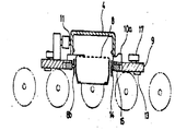
제1도는 종래부터 가장 많이 채용되고 있는 노광장치의 일례를 표시한 것으로서, 동 도면에 있어서, 장치 케이스(1)내에는 초고압 수은등으로 된 노광광원(2) 및 램프하우스(3)와, 케이스(1)상부에는 패널(4)을 위치 결정 재치하는 톱플레이트(5)를 가지고 있으며, 노광광원(2)과 패널(4)과의 사이에는 보정렌즈(6) 및 필터(7)가 배설되어 있다. 또한, (8)은 패널(4)의 안쪽에 장착되는 새도우마스크이다.FIG. 1 shows an example of an exposure apparatus which has been adopted the most in the related art. In the drawing, in the apparatus case 1, an exposure light source 2 made of an ultra-high pressure mercury lamp, a lamp house 3, and a case ( 1) The
종래의 노광공정 자동화의 경우에는, 패널(4)과 새도우마스크(8)를 결합한 한조의 워크를, 진공흡착법에 의해서 이재하는 패널이재기를 사용해서 상기의 톱플레이트(5)상에 공급하고, 노광완료후는 다시 패널이재기로 다음 공정에 이재하고 있었다.In the case of the conventional exposure process automation, a set of workpieces in which the panel 4 and the
그러나, 5형, 6형 등의 소형컬러브라운관을 대상으로 한 경우, 오우버헤드형의 이재기를 적용하는 것은, 장치를 설비하는데 공간적으로나 생산비면에서도 불이익이 된다는 문제가 있었다.However, in the case of small color CRTs such as 5 type and 6 type, the application of the overhead type transfer machine has a problem in that it is disadvantageous in terms of space and production cost for installing the apparatus.
따라서 본 발명은 상기한 종래의 문제를 감안하여 이루어진 것으로서, 그 목적으로 하는 바는, 콘베이어라인과 노광장치간의 이재를 직결하고, 자동화시스템을 보다간략화시킨 팰리트를 제공하는데 있다.Accordingly, the present invention has been made in view of the above-described conventional problems, and an object thereof is to provide a pallet in which a transfer system between the conveyor line and the exposure apparatus is directly connected and the automation system is further simplified.
이와 같은 목적을 달성하기 위하여 본 발명은, 톱플레이트와 워크반송용의 팰리트를 조합해서 팰리트를 구성한 것이다.In order to achieve the above object, this invention combines the top plate and the pallet for workpiece conveyance, and comprises the pallet.
다음에 도면을 사용해서 본 발명의 실시예를 상세히 설명한다.EMBODIMENT OF THE INVENTION Next, the Example of this invention is described in detail using drawing.
제2도, 제3도는 본 발명에 의한 팰리트의 일례를 표시하며, 제2도는 요부단면도, 제3도는 그 평면도이다. 이들 도면에 있어서, 팰리트(9)에는, 패널(4)을 재치하기 위한 패널받침(10a)(10b)(10c)과 노광작업에서 수평방향의 기준이 되는 3개의 기준나일론보올(11)과, 팰리트(9)의 위치결정기준이 되는 3매의 측면기준판(12)과, 높이방향의 기준이 되는 3매의 하면기준판(13)과, 새도우마스크(8)를 수용하기 위한 더미핀(14)을 착설한 마스크를(15)과, 새도우마스크 착탈작업용의 3개의 기준구멍(16)과, 콘베이어상에서 원활하게 반송시키는 로울러베어링을 사용한 주행로울러(17)를 구비하고 있다. 한편, 노광장치쪽에는, 팰리트(9)를 반입, 반출하기 위한 로울러베어링을 사용한 주행로울러(17)를 구비하고 있다. 한편, 노광장치쪽에는, 팰리트(9)를 반입, 반출하기 위한 반송로울러 유니트(18)가 케이스(1)에 부착되어 있어서 도시되지 않는 에어실린더에 의한 리프트기구(19)로 승강가능하도록 되어있다. 그리고, 팰리트(9)의 위치결정은 측면기준판(12)에 상대하는 위치에 고정기준점(20)이 있으며, 마찬가지로 팰리트(9)의 하면에는 팰리트받침(21)이 착설되어 있다. 또, 팰리트위치결정용 고정기준점(20)과 팰리트(9)를 협지하는 반대측에는 푸셔장치가 있으며, 이 푸셔장치의 제1브래킷(22)에 부착한 선단에 패드(23)를 구비한 에어실린더(24)는 팰리트(9)의 위치결정용이고, 선단에 나일론로울러(25)를 부착한 에어실린더(24)는 패널(4)의 푸셔이다. 또, 상기 제1브래킷(22)과 직각방향이 되는 다른면쪽에도 마찬가지로 제2브래킷(27)을 구비하고, 팰리트(9) 및 패널(4)용의 푸셔가 착설되어 있다. 또한, (28)은 팰리트스토퍼이다.2 and 3 show an example of a pallet according to the present invention. FIG. 2 is a sectional view of a main portion, and FIG. 3 is a plan view thereof. In these figures, the pallet 9 includes panel supports 10a, 10b and 10c for mounting the panel 4, three
다음에, 본 발명에 의한 팰리트를 사용한 새도우마스크부착기를 제4도를 사용해서 설명한다. 여기서 팰리트(9)는 상기 노광장치용과 똑같은 것으로서, 새도우마스크(8)가 수용가능하게 되어있다. 동 도면에 있어서, (30)은 팰리트(9)를 쳐올려서 선단의 테이퍼핀(31)에 의해서 팰리트(9)의 위치결정을 행하는 기축이다. 그리고 이 기축(30)에 안내통(32)을 일체가 되게 한 승강기판(33)이 에어실린더등에 의해서 승강할 수 있는 구조로 되어있다. 또, 이 승강기판(33)상에는 중앙에 새도우마스크(8)의 프레임부(8a)를 지지하기 위한 지지대(34)가 기대(35)를 개재해서 배설되어 있다. 또, 이 지지대(34)에는 링크기구에 의해서 새도우마스크(8)의 프레임(8a)을 클램프하는 클램프기구가 결합되어 있다. 이 클램프기구는 지지대(34)의 원통부(36)가 승강기판(33)의 하방에 돌출되어 있어서 브래킷(37)을 부착하고 있다. 그리고, 이 브래킷(37)에는 클램프동작을 행하는 에어실린더(38)가 부착되어 있어서, 에어실린더(38)의 진퇴동작에 의해서 연결로드(39)를 승강시킨다. 또, 클램프클릭(40)은 연결로드(39)의 상승에 따라서 상대방향으로 클램프핀(41)을 지지점으로 하여 회동하여, 새도우마스크(8)의 프레임(8a)의 하면을 압압해서 고정하는 기구이다. 또한 기대(35)에는 슬라이드축(42)이 착설되어 있어서, 슬라이드블록(43)이 도시되지 않는 에어실린더의 진퇴동작에 의해서 슬라이드할 수 있는 구조로되어있어 슬라이드블록(43)상에는 새도우마스크(8)의 스프링(8b)을 신축자재하게 동작시키기 위한 연결클릭(44)이 부착되어 있다.Next, the shadow mask attaching machine using the pallet which concerns on this invention is demonstrated using FIG. Here, the pallet 9 is the same as that for the said exposure apparatus, and the
다음에 이상 설명한 장치로 본 발명의 팰리트를 사용한 실시예에 대하여 설명한다.Next, the Example using the pallet of this invention with the apparatus demonstrated above is demonstrated.
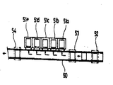
제5도는 일실시예의 장치배치도이다. 동 도면에 있어서. (50)은 콘베어어라인, (51a)(51b)(51c)(51d)(51e)는 노광장치이다. (52)는 제1스테이션이며 상기 제4도에 표시한 새도우마스크 부착기가 배설되어 있다. 또, 제2스테이션(53)에는 패널(5)에 새도우마스크(8)를 장착하는 마스크장착기가 부착되어 있으며, 제3스테이션(54)에는 노광완료후 패널(4)로부터 새도우마스크(8)를 떼어내는 마스크탈기가 배설되어 있다.5 is a device arrangement diagram of one embodiment. In the figure. Reference numeral 50 denotes a conveyor line, and 51a, 51b, 51c, 51d and 51e are exposure apparatuses. Reference numeral 52 is a first station, and the shadow mask attaching device shown in Fig. 4 is disposed. In addition, a mask mounting device for mounting the
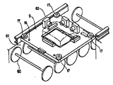
제6도, 제7도는 콘베어어상의 팰리트의 주행상태를 표시하고, 제8도는 노광장치(51a)∼(51e)에 팰리트(9)를 들여보내는 직각이재 콘베이어이다.6 and 7 show the running state of the pallet on the conveyor, and FIG. 8 is a right angle transfer conveyor which feeds the pallet 9 into the exposure apparatus 51a to 51e.
먼저, 제5도에 있어서, 제1스테이션에서 팰리트(9)에 새도우 마스크(8)와 패널(4)을 공급한다. 제4도로 설명하면, 빈 팰리트를 콘베이어(50)의 제1스테이션(52)에서 정지시킨 다음, 기축(30)을 쳐올려서 테어퍼핀(31)으로 팰리트(9)를 위치결정시킨다. 동시에 승강기판(33)이 정위치까지 상승한다. 이때 클램프클릭(40) 및 연결클릭(44)은 개방상태로 해두고, 새도우마스크(8)는 스프링(8b)을 휘게한 상태로 지지대(34)상에서 재치한다. 그후, 에어실린더(38)를 돌출시켜, 연결로드(39)를 상승시키므로서, 클램프클릭(40)을 동작시켜, 플레임(8a)의 저면을 지지대(34)상에 고정한다. 이어서 슬라이드블록(43)을 지지대측에 밀어붙여서 새도우마스크(8)의 스프링(8b)을 연결클릭(44)으로 프레임(8a)쪽에 닫는다. 이 상태로 스프링(8b)의 구멍위치와 팰리트(9)내의 더미핀(14)이 일치하는 높이까지 승강기판(33)을 하강시켜, 일치된 위치에서 정지시키고, 닫혀져있는 연결클릭(44)을 개방해서 스프링(8b)을 더미판(14)에 감합시킨다. 그뒤 에어실린더(38)를 들어오게 하여 클램프클릭(40)을 개방하고, 승강기판(33)과 기축(30)을 하강시킨다. 이 경우, 팰리트(9)는 새도우마스크(8)를 수용한상태로 콘베이어(50)의 반송면에 놓이게 된다. 그리고, 새도우마스크(8)를 수용한 팰리트(9)에는 짝이되는 패널(4)을 패널받침(10a)(10b)(10c)상에 재치해서 작업을 완료한다. 그 상태가 제6도이다. 다음에 제5도에 표시한 제2스테이션(53)에서는 상기 제1스테이션(52)과 마찬가지인 제4도에서 설명한 구조에 의한 새도우마스크 부착기를 사용하여, 패널(4)에 새도우 마스크(8)를 장착한다. 그리고, 팰리트(9)는 새도우마스크(8)를 더미핀(14)에 지지한 상태 혹은 새도우마스크(8)를 패널(4)내에 장착한 상태에 있어서도 제7도에 표시한 바와 같이 똑같이 콘베이어(50)상을 반송할 수있다. 또한, 이 실시예에서는 어쿰로울러방식의 플로어콘베어어를 사용하여, 수지제의 회전로울러(60)상을 팰리트(9)가 반송한다. 또, 콘베이어프레인(61)의 양단상면에는 반송을 원활하게 하기 위한 가이드레일(62)을 구비하고 있다. 다음에 제2스테이션(53)에서 패널(4)과 새도우 마스크(8)를 일체가 되게 한뒤, 팰리트(P)는 노광장치(51a)∼(51e)상에 반입하고, 반출한다. 이 실시예에서는 제8도에 표시한 직각이재 콘베이어를 사용했다. 다음에 해당하는 노광장치의 직각이재 콘베이어상에서 팰리트(9)를 정지시킨 뒤, 에어실린더(64)를 쳐올려서 이재 유니트(65)에 의해서 콘베이어(50)의 라인과 직각방향에 팰리트(9)를 이재한다. 그때에 노광장치와의 이재를 원활하게 행하기 위하여 보조로울러유니트(66)를 부착했다. 또한 (67)은 팰리트스토퍼이다.First, in FIG. 5, the
다음에, 제2도, 제3도로 되돌아가서 설명한다. 콘베이어(50)로부터 이재된 팰리트(9)는, 리프트기구(19)에 의해서 상승되어 있는 반송로울러유니트(18)상에 반입하고, 스토퍼(28)에 부딪치게 하여 정지시킨다. 다음에 반송로울러유니트(18)를 하강시켜서 팰리트(9)를 팰리트받침(21)상에 재치한다. 그후 에어실린더(24)(25)및 다른쪽도 마찬가지로 동작시켜서, 팰리트(9)와 패널(4)의 위치결정을 행한다. 그리고, 위치결정완료후, 노광작업을 행하고, 노광완료후는 재차 반송로울러유니트(18)를 상승시켜서 콘베이어(50)상에 반출한다. 그리고, 콘베이어(50)상에 되돌린 팰리트(9)는 제3의 스테이션(54)에서 마스크 탈기에 의해서 패널(4)내의 새도우마스크(8)가 재차 팰리트(9)내의 더미핀(14)에 지지되어서 제6도에 표시한 상태에서 다음의 공정으로 반송할 수 있다.Next, a description will be given with reference to FIG. 2 and FIG. The pallet 9 transferred from the conveyor 50 is carried in on the
또한, 상기한 실시예에 있어서는, 5대의 노광장치를 콘베이어와 병렬로 배설한 경우에 대해서 설명하였으나, 필요에 따라서 대수를 정할 수 있는 것은 당연하며, 또, 다품종 노광장치를 사용하면, 해당하는 품종의 팰리트를 준비하므로서 용이하게 다품종생산라인이 되는 등 자동화라인을 구성하는데에 효과는 극히 큰 것이다.In addition, in the above-described embodiment, the case in which five exposure apparatuses are arranged in parallel with the conveyor has been described. However, it is natural that the number can be determined as needed. It is extremely effective in constructing an automation line, such as easily preparing multiple pallets by preparing a pallet of metal.
이상 설명한 바와 같이 본 발명에 의한 팰리트에 의하면, 새도우마스크의 착탈작업에서부터 노광작업 및 그간의 워크의 반송을 일관해서 행할 수 있으므로, 반송시스템의 간략화를 용이하게 실현할 수 있는 등의 극히 뛰어난 효과를 얻을 수 있다.As described above, according to the pallet according to the present invention, since the shadow mask can be detached from the exposure operation and the conveyance of the workpieces can be carried out consistently, extremely excellent effects such as simplifying the conveying system can be easily realized. You can get it.
Claims (1)
Applications Claiming Priority (2)
| Application Number | Priority Date | Filing Date | Title |
|---|---|---|---|
| JP57206184A JPS5996629A (en) | 1982-11-26 | 1982-11-26 | Pallet for manufacturing color cathode-ray tube |
| JP206184 | 1982-11-26 |
Publications (2)
| Publication Number | Publication Date |
|---|---|
| KR840006870A KR840006870A (en) | 1984-12-03 |
| KR880000101B1 true KR880000101B1 (en) | 1988-02-23 |
Family
ID=16519199
Family Applications (1)
| Application Number | Title | Priority Date | Filing Date |
|---|---|---|---|
| KR1019830005580A KR880000101B1 (en) | 1982-11-26 | 1983-11-25 | Pallette for manufacturing of colour-braun tube |
Country Status (5)
| Country | Link |
|---|---|
| US (1) | US4648346A (en) |
| JP (1) | JPS5996629A (en) |
| KR (1) | KR880000101B1 (en) |
| FR (1) | FR2536907B1 (en) |
| GB (1) | GB2132010B (en) |
Families Citing this family (7)
| Publication number | Priority date | Publication date | Assignee | Title |
|---|---|---|---|---|
| JPS6168828A (en) * | 1984-09-12 | 1986-04-09 | Sony Corp | Color phosphor screen making device |
| JPS62157633A (en) * | 1985-12-28 | 1987-07-13 | Tsubakimoto Chain Co | Panel and shadow mask mounting device for color cathode-ray tube manufacturing equipment |
| FR2623328B1 (en) * | 1987-11-13 | 1990-02-16 | Videocolor | DEVICE FOR HOLDING A POSITION OF A SUBSTANTIALLY PARALLELEPIPEDIC SHAPE |
| DE4326275C2 (en) * | 1993-08-05 | 1997-10-09 | Erowa Ag | Method for positioning a workpiece carrier in a processing machine and workpiece carrier for performing the method |
| KR100268332B1 (en) * | 1997-12-30 | 2000-10-16 | 윤종용 | Method and apparatus for extracting start signal of automatic equipment |
| US6620252B2 (en) * | 2001-10-29 | 2003-09-16 | Thomson Licensing S.A. | Metallization module for cathode-ray tube (CRT) applications |
| JP5637698B2 (en) | 2010-02-09 | 2014-12-10 | 株式会社島精機製作所 | Knitting yarn holding device for flat knitting machine |
Family Cites Families (7)
| Publication number | Priority date | Publication date | Assignee | Title |
|---|---|---|---|---|
| US3949226A (en) * | 1972-05-26 | 1976-04-06 | Zenith Radio Corporation | Automatic light intensity controller for CRT lighthouse |
| US4138774A (en) * | 1976-07-28 | 1979-02-13 | Hitachi, Ltd. | Panel positioning apparatus |
| JPS5918819B2 (en) * | 1976-08-11 | 1984-05-01 | 株式会社日立製作所 | Shadow mask removal device |
| JPS5937955Y2 (en) * | 1977-04-04 | 1984-10-22 | 株式会社日立製作所 | Color picture tube panel coating equipment |
| US4331228A (en) * | 1980-05-05 | 1982-05-25 | Visi-Trol Engineering Company | Roller conveyor system |
| JPS5786446U (en) * | 1980-11-14 | 1982-05-28 | ||
| JPS6044776B2 (en) * | 1981-06-05 | 1985-10-05 | 株式会社日立製作所 | Shadow mask removal device |
-
1982
- 1982-11-26 JP JP57206184A patent/JPS5996629A/en active Granted
-
1983
- 1983-11-24 GB GB08331357A patent/GB2132010B/en not_active Expired
- 1983-11-25 KR KR1019830005580A patent/KR880000101B1/en not_active IP Right Cessation
- 1983-11-25 FR FR8318883A patent/FR2536907B1/en not_active Expired
-
1986
- 1986-03-28 US US06/845,617 patent/US4648346A/en not_active Expired - Fee Related
Also Published As
| Publication number | Publication date |
|---|---|
| JPS5996629A (en) | 1984-06-04 |
| KR840006870A (en) | 1984-12-03 |
| JPH0415973B2 (en) | 1992-03-19 |
| FR2536907A1 (en) | 1984-06-01 |
| FR2536907B1 (en) | 1986-12-12 |
| GB2132010B (en) | 1986-08-06 |
| GB2132010A (en) | 1984-06-27 |
| GB8331357D0 (en) | 1984-01-04 |
| US4648346A (en) | 1987-03-10 |
Similar Documents
| Publication | Publication Date | Title |
|---|---|---|
| KR890000577B1 (en) | Automatic assembly machine | |
| CA1188488A (en) | Method and apparatus for supplying parts to an automatic assembling machine | |
| JPWO2016199207A1 (en) | Printing apparatus and substrate working apparatus | |
| KR880000101B1 (en) | Pallette for manufacturing of colour-braun tube | |
| CN115172206B (en) | Wafer production equipment and method | |
| US4130919A (en) | Apparatus for removing a shadow mask assembly from a panel and inserting same into a dummy panel | |
| CN217018970U (en) | Platform is refuted to arm between chip mounter | |
| KR860001674B1 (en) | Method of conveying panel and shadow mask and pallet for holding pannel and shadow mask and apparatus for removing shadow mask from pannel | |
| WO2015076489A1 (en) | Film transfer system | |
| JP3034320B2 (en) | Automatic piston assembly device | |
| CN220784902U (en) | Automatic assembly line for auxiliary materials of notebook shell | |
| CN219468958U (en) | X-ray paster point material machine | |
| CN218909052U (en) | Transition conveying device of plane screen printer | |
| CN220822865U (en) | Accurate alignment assembling machine for stator and rotor of motor | |
| CN218930075U (en) | Automatic labeling and blanking equipment | |
| CN218707166U (en) | Curing device and process equipment | |
| JP3075982B2 (en) | Shadow mask mounting device | |
| JPH0555798A (en) | Board conveyor and correcting method for board position thereof | |
| JPH09131623A (en) | Transport device using pallet | |
| JPH1116493A (en) | Manufacturing equipment and manufacture of explosion proof cathode ray tube | |
| KR200142324Y1 (en) | Funnel moving apparatus for crt | |
| JPH09244257A (en) | Exposure device | |
| KR100189810B1 (en) | Getter auto-welding system of cathode ray tube | |
| KR200147277Y1 (en) | Automatic explosion-proof band supplying apparatus for crt | |
| KR100398321B1 (en) | Method for loading/unloading single array module printed circuit board |
Legal Events
| Date | Code | Title | Description |
|---|---|---|---|
| A201 | Request for examination | ||
| G160 | Decision to publish patent application | ||
| E701 | Decision to grant or registration of patent right | ||
| GRNT | Written decision to grant | ||
| FPAY | Annual fee payment |
Payment date: 20020225 Year of fee payment: 15 |
|
| LAPS | Lapse due to unpaid annual fee |