KR870000320B1 - Color cathode ray tube apparatus - Google Patents
Color cathode ray tube apparatus Download PDFInfo
- Publication number
- KR870000320B1 KR870000320B1 KR8203534A KR820003534A KR870000320B1 KR 870000320 B1 KR870000320 B1 KR 870000320B1 KR 8203534 A KR8203534 A KR 8203534A KR 820003534 A KR820003534 A KR 820003534A KR 870000320 B1 KR870000320 B1 KR 870000320B1
- Authority
- KR
- South Korea
- Prior art keywords
- correction
- magnetic field
- cathode ray
- dynamic
- ray tube
- Prior art date
Links
Images


Classifications
-
- H—ELECTRICITY
- H04—ELECTRIC COMMUNICATION TECHNIQUE
- H04N—PICTORIAL COMMUNICATION, e.g. TELEVISION
- H04N9/00—Details of colour television systems
- H04N9/12—Picture reproducers
- H04N9/16—Picture reproducers using cathode ray tubes
- H04N9/28—Arrangements for convergence or focusing
-
- H—ELECTRICITY
- H01—ELECTRIC ELEMENTS
- H01J—ELECTRIC DISCHARGE TUBES OR DISCHARGE LAMPS
- H01J29/00—Details of cathode-ray tubes or of electron-beam tubes of the types covered by group H01J31/00
- H01J29/46—Arrangements of electrodes and associated parts for generating or controlling the ray or beam, e.g. electron-optical arrangement
- H01J29/70—Arrangements for deflecting ray or beam
- H01J29/701—Systems for correcting deviation or convergence of a plurality of beams by means of magnetic fields at least
- H01J29/702—Convergence correction arrangements therefor
- H01J29/705—Dynamic convergence systems
-
- H—ELECTRICITY
- H01—ELECTRIC ELEMENTS
- H01J—ELECTRIC DISCHARGE TUBES OR DISCHARGE LAMPS
- H01J2229/00—Details of cathode ray tubes or electron beam tubes
- H01J2229/56—Correction of beam optics
- H01J2229/563—Aberrations by type
- H01J2229/5637—Colour purity
Abstract
Description
제1도는 종래의 칼라음극선관장치의 네크(neck)부 개요도.1 is a schematic view of a neck portion of a conventional color cathode ray tube device.
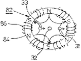
제2도는 (a)(b)는 다이나믹콘버젠스(Dynamic Convergence)보정자계 발생 소자의 구성도.2 is a block diagram of a dynamic convergence correction field generating element.
제3도는 다이나믹 콘버젠스 보정자계발생소자의 설정위치와 보정전력과의 관계도.3 is a relationship between the setting position and the correction power of the dynamic convergence correction field generating element.
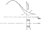
제4도는 편향요크(yoke)자계분포중에 다이나믹 콘버젠스 보정자계발생소자를 배치하였을때의 자계분포의 설명도.4 is an explanatory diagram of a magnetic field distribution when a dynamic converence correction magnetic field generating element is disposed in a deflection yoke magnetic field distribution.
제5도는 본 발명의 한 실시예에 관한 칼라 음극선관 장치의 네크부 개요도.5 is a schematic view of a neck portion of a color cathode ray tube device according to an embodiment of the present invention.
* 도면의 주요부분의 대한 부호의 설명* Explanation of symbols for the main parts of the drawings
3 : 전자총 5 : 편향요크3: electron gun 5: deflection yoke
6 : 스타틱(static)보정자계발생소자 7 : 코마(coma)보정용자계발생소자6: static correction field generator 7: coma correction field generator
11 : 간격 36, 37 : 전극11:
81 : 4극자계발생소자 82 : 6극자계발생소자81: 4-pole field generator 82: 6-pole field generator
83, 84 : 코아 85, 86 : 코일83, 84: core 85, 86: coil
87 : 축방향 중심선87 axial center line
본 발명은 다이나믹 콘버젠스 보정자계발생소자의 전자총에 대한 배치구성을 개선한 인라인(In line)방식의 칼라음극선관 장치에 관한 것이다.The present invention relates to an in-line color cathode ray tube device having an improved arrangement of an electromagnetic gun of a dynamic convergence correction field generator.
종래, 인라인방식의 칼라음극선관장치에 있어서는, 편향요크의 자계분포를 균일하지 않은 적당한 자계분포로하여, 전자총의 선단부에 자계제어소자를 삽입하고, 그 양자의 조합으로서 인라인 배열의 3전자비임을 화면에서 집중시켰던 것이다. 그런데, 편향요크자계의 제조상오차, 자계분포의 정밀도, 전자 총에서 방출되는 전자비임의 정열(整列)의 정밀도, 전자비임과 편향요크의 조합의 정밀도등에 양산상(量産上)의조립오차가 생겨 회무상의 전영역에서 3전자비임을 높은 정밀도로서 집중시킬수가 없었다.Conventionally, in the inline type color cathode ray tube apparatus, the magnetic field distribution of the deflection yoke is made into a uniform non-uniform magnetic field distribution, a magnetic field control element is inserted at the front end of the electron gun, and the combination of both is used to display three electron beams in an inline array. I focused on. However, there is a production error in the production phase of the deflection yoke magnetic field, the accuracy of the magnetic field distribution, the accuracy of the alignment of the electron beam emitted from the electron gun, and the precision of the combination of the electron beam and the deflection yoke. It was not possible to concentrate three electron beams with high precision in all areas of the business.
이경우 콘버젠스의 잔존부분은 양산정밀도에서 0.5-1.0mm였다.특히,인라인방식의 칼라음극선관을 계산기단말용 디스플레이(Display)소자로서 사용하게 되면, 화면주변에서의 색채의 엇갈림, 즉 음극선관화면에 표현되는 문자의 엇갈림현상이 나타나서, 디스플레이소자로서의 품질을 저하시킨다. 이에대하여,칼라음극선관의 네크부외주에 다이나믹 콘버젠스 보정자계발생소자를 장착시켜, 종래방식의 콘버젠스의 잔존부분 0.5-1.0mm를 보정함으로서, 화면주변에서의 색채의 엇갈림을 해결하는 방안이 제안되었다.In this case, the remaining part of the converence was 0.5-1.0mm in mass production accuracy. Especially, when the in-line color cathode ray tube is used as the display device for the calculator terminal, the color shift around the screen, that is, the cathode ray tube screen Staggering of the characters expressed on the screen appears, which degrades the quality of the display element. On the other hand, a dynamic convergence correction field generating element is mounted on the outer periphery of the neck portion of the color cathode ray tube to correct 0.5-1.0 mm of the remaining portion of the conventional converence, thereby solving the color shift around the screen. Proposed.
이러한 방법은 종래부터 여려형태로서 제안되어 왔었다.This method has conventionally been proposed in various forms.
제1도는 위의 제안을 기초로한 인라인방식의 칼라음극선관장치(1)에 있어서의 네크부개요도이다. 이 도면에 있어서, 네크부(2)의 가운데에는 인라인배열의 3전자비임(31)(32)(33)을 발생시키는 전자총(3)이 삽입되어 있다. 이 전자총(3)에는 베이스부(4)에서 각전압이 인가되므로, 3전자비임(31)(32)(33)이 발생하게 된다.3전자비임(31)(32)(33)은 비균일의 특수한 자계분포를 발생시키는 펀향요크(5)에서 수평, 수직방향으로 화면전체에 걸쳐 편향시킨다. 전자총(3)의 외주부에는, 예컨데 2극, 4극, 6극, 마그네트로된 스타틱 보정자계발생소자(6)가 설치되어 있고, 이소자(6)에 의해 화면중앙부에서 3전자비임(31)(32)(33)의 집중잔존부분을 보정시켜 한점에 집중시킴과 동시에 화면의 색순도 보정도하게된다. 전자는 4극마그네트및 6극마그네트로, 후자는 2극마그네트로 각각 자계의 세기를 가변시켜 보정하게되는 것이다.1 is a schematic view of a neck portion of an inline type color cathode
화면중앙에서 한점에 집중시킨 3전자비임(31)(32)(33)은 편향요크에서 발생하는 자계분포의 가운데를 통과함으로서 수평, 수직으로 편향시키지만, 화면상의 전영역에서 3전자비임(31)(32)(33)을 집중시킬 필요가 있다. 이때문에 편향요크(5)에서 발생하는 자계를 수평, 수직모두 균일하지 않은 특수한 자계분포로함과 동시에 코마(coma)보정을 하기위해서 전자총(3)의 선단에 코마보정용 자계제어소자(7)을 설치하여 중앙비임(32)과 양사이드비임(31)(33)의 편향감도보정(偏向感度補正)을 하고 있다.The three
위에서와 같이 보정된 3전자비임(31)(32)(33)을 다시양면주변에서의 집중정밀도를 향상시키기 위해 편향요크(5)와 스타딕 보정자계발생소자(6)과의 사이에 설치된 다이나믹 콘버젠스 보정자계발생소자(8)에서 발생하는 자계에 의해 양사이드 비임(31)(32)이 보정되어 중앙비임(32)에 집중되는 것이다. 따라서, 콘버젠스 잔존부분을 0.5mm이하로 할수있다· 이 다이나믹 콘버젠소 보정자계발생소자(8)은 제2도(a)(b)에표시한 바와같이 4극자계 발생소자(81)과 6극자계발생소자(82)로 구성된 것으로서, 링상 페라이트(Ferrite)코아(83)(84)에 감겨진코일(85)(86)의 전류를 가변함으로 인하여 각자계강도를 가변할수있다.Dynamics provided between the deflection yoke 5 and the stadical correction field generating element 6 in order to improve the concentration accuracy at both sides of the three
그런데, 다이나믹 콘버젠스 보정자계 발생소자(8)중에서 6극자계발생소자(82)의 보정감도가 매우 나쁘고, 그 보정때문에 코일(86)이 흐르는 전류가 많아져 보정전력이 불필요하게 크게되고, 보정회로의 크스트를 비싸게함과 동시에 코일(86)의 발열을 유기하게되어 다이나믹보정의 드리프트(drift)를 일으키는 등의 불합리성이 있었다. 따라서, 본 발명은 다이나믹 콘버젠스 보정자계 발생소자의 전자총에 대한 배치를 가장적당하게하여 다이나믹 콘버젠스 보정자계 발생소자의 보정감도를 향상시키고 보정전력을 경감할 수 있는 인라인방식의 칼라음극선관을 제공하는데 그 목적이 있는 것이다.However, the sensitivity of the six-pole magnetic
이하, 본 발명의 한 실시예를 도면에 의하여 설명한다.Hereinafter, an embodiment of the present invention will be described with reference to the drawings.
제3도는 다이나믹 콘버젠스보정자계 발생소자(8)의 보정전력이 큰 6극자계 발생소자(82)의 전자총(3)에 대한 설정위치와, 이때의 보정전력과의 관계를 그라프로서 표시한 것이다.3 is a graph showing the relationship between the setting position of the six-pole magnetic
제3도에 표시한 일반적인 바이포텐샬(bipo tential)형의 전자총(3)은 인라인으로 배열된 3개의 캐소드 (39),제1그리드(34),제2그리드(35),제3그리드(36)(이하제3전극이라고한다) 제4그리드(37)(이하 제4전극이라고 한다) 및 실드컵(shield cup) 전극(38)등으로 되어있다.The general bipotential type electron gun 3 shown in FIG. 3 includes three
최근에는 다단집속형 전자총이 사용되고 있으나, 이는 기본적으로 제3도에 표시한 전자총 구성과 유사하다. 즉 제3전극(36)과 제4전극(37)과의 사이에서 구성되는 주전자렌즈가 있고, 이전단에 여러종류의 프리포커스(prefocase)렌즈를 여러개 배실한다. 바이포텐샬형 전자총은 1개의 프리포커스렌즈를 배설한 것이다.Recently, a multi-stage focused electron gun has been used, but this is basically similar to the configuration of the electron gun shown in FIG. That is, there is a teapot lens formed between the
제3도이 있어서, Z는 관축(管軸)이다.In FIG. 3, Z is a tube axis.
일반적으로 코마보정용 자계제어소자(제1도)(7)는 제4전극(37)과 실드컵전극(38)과의 경계부(9)이 설치되어 있다.Generally, the comma correction magnetic field control element (FIG. 1) 7 is provided with the boundary 9 between the 4th electrode 37 and the
제3도에 있어서, 그라프(a)는 코마보정용자계제어소자(7)이 없을경우 ㅡ라프(6)는 코마보정용자계제어소자(17)를 배치하였을 경우의 보정전력의 변화를 표시한 것이다.In Fig. 3, the graph (a) shows a change in correction power when the comma correction magnetic field control element 17 is disposed when the coma correction magnetic
제3도에 표시한 것과같이 다이나믹 콘버젠스 보정자계발생소자(8)의 보정전력은 코마보정용 자계제어소자(7)의 유무에 관계없이 전자총(3)의 주렌즈부근방에서 최소로 된다는 것이 판명되었다. 또 코마보정용계자제어소자(7)을 설치하면, 보정전력의 최소위치는 거의 변하지 않는다. 그 최소치의 값이 크게된다는 것이 판명되었다. 이 보정전력의 최소치는 코마보정용 자계제어소자(7)과의 상대거리에도 관계가 있다.As shown in FIG. 3, it is found that the correction power of the dynamic convergence correction field generating element 8 is minimized near the main lens of the electron gun 3 regardless of the presence or absence of the comma correction
제4도와 같이, 편향분포의 가운데에 다이나믹 콘버젠스 보정자계 발생소자(8)를 배치하고, 이때의 수직자계분포를 측정하였더니 점선 b와 같이 다이나믹 콘버젠스 보정자계발생소자(8)이 없을 때는 실선 a와 같이되고, 소자(8)를 설치하였을 경우에는 수직자계분포의 총측(銃側)의 자계가 어느정도 감소된다는 것을 알수있다.또 수평자계분포의 변화는 대단히 적다는 것을 알수 있으며, 이것은 일반적으로 다이나믹콘버젠스 보정자계발생소자(8)로서 링상 페라이트코아를 사용하고, 이링코아에 동선을 권착시켜 4극자계, 6극자계를 구성하였기 때문이며, 수직자계분포의 총측성분이 링코아로 션트(shunt)시켰기 때문이다.As shown in FIG. 4, when the dynamic converence correction magnetic field generating element 8 is disposed in the center of the deflection distribution, and the vertical magnetic field distribution is measured, when there is no dynamic converence correction magnetic field generating element 8 as shown by the dotted line b. When the element 8 is provided and the element 8 is provided, it can be seen that the magnetic field on the total side of the vertical magnetic field distribution is somewhat reduced. Also, the change in the horizontal magnetic field distribution is very small. This is because a ring-shaped ferrite core is used as the dynamic converence correction magnetic field generating element 8, and four-pole and six-pole magnetic fields are formed by winding copper wires on the ring core, and the total component of the vertical magnetic distribution is a ring core shunt ( shunt).
이때문에 코마보정용 자계제어소자(7)는 다이나믹 콘버젠스 보정자계 발생소자(8)가 없을경우(그라프a)에 비교하여 다이나믹 콘버젠스 보정자계발성소자(8)를 설치하면 그 형상, 크기를 크게하여 자계를 제어할 필요가 있다. 그렇기 때문에 다이나믹 콘버젠스 보정자계 발생소자(8)의 보정전력이 불필요하게 증대하게 되어 바람직하지 못하다. 따라서, 코마보정용자계제어소자(7)는 다이나믹콘버젠스 보정 자계제어소자 (8)에서 떨어지게할 필요가 있다.For this reason, the comma correction magnetic
즉 제4도에 표시한 것과같이 다이나믹 콘버젠스 보정자계발생소자(8)의 내부에 들어가지 못하도록 배치할 필요가 있다.That is, it is necessary to arrange | position so that it may not enter inside the dynamic convergence correction field generating element 8 as shown in FIG.
제5도는 본 발명의 다이나믹 콘버젠스 보정자계 발생소자(8)의 설치구성의 한실시예인데 네크부(2)의 외주에서 편향요크(5)와 스타틱 보정자계 발생소자(6)과의 사이에 설치된 4극,6극으로된 다이나믹 콘버젠스 보정자계발생소자(8)는 보정전력의 최소치를 표시한 주렌즈부, 결국 제3전극(36)과 제4전극(37)로 구성된 전자렌즈부에 배치되고 코마 보정용 자계제어소자(7)은 다이나믹 콘버젠스 보정자계발생소자(8)의Z축(과축)상 영역외(領域外), 즉 이소자(8)의 폭방향의 치수영역(10)와의 편향요크(5)측에 설치되어 있다. 따라서, 코마보정용 자계제어소자(7)의 크기를 불필요하게 크게하지 않고 다이나믹 콘버젠스 보정자계발생소자(8)의 보정감도를 향상시켜 보정전력을 감소시킬수 있다.5 is an embodiment of the installation configuration of the dynamic converence correction magnetic field generating element 8 of the present invention, which is provided between the deflection yoke 5 and the static correction magnetic field generating element 6 at the outer circumference of the
또 위의 실시예의 경우, 정확하게는 다이나믹 콘버젠스 보정자계 발생소자(8)는 보정전력의 최소치를 나타내는 점(點)에 설정하기 위해 그 축방향중심선(제5도)(87)를 화면측의 제일높은 고압전극인 제4전극(37)과 제3전극(36)(37)의 간격(11)의 크기를)예컨데 1mm)로 하였을경우, 다이나믹 콘버젠스 보정자계발생소자(8)의 축방향중심선(87)은 간격(11)의 중심을 포함하고 있으며 이중심에서 편향요크(5)측 혹은 스타틱 보정자계발생소자 (b)측으로의 3d의 범위에 있어서는 보정감도가 적게 열하되므로 그 설정오차내에서 이루어질수 있다. 또 위의 실시예에서, 전자총(3)은 바이토텐셜형 전자총에 관하여 설명하였으나,다른 다단 집속형 전자총에 관하여서도 성립할수 있는 것이다.In addition, in the case of the above embodiment, the dynamic convergence correction magnetic field generating element 8 accurately sets its axial center line (figure 5) 87 on the screen side in order to set at the point representing the minimum value of the correction power. When the size of the interval 11 between the fourth electrode 37 and the
즉 다단집속형 전자총의 주렌즈의 정의(定義)로서, 캐소드(39)에서 방출되는 전자비임은 각전자렌즈에서 집속되지만, 최후에 집속시키는 전자렌즈를 주전자렌즈라 한다.That is, as the definition of the main lens of the multi-stage focused electron gun, the electron beam emitted from the
이상 설명한 바와같이 본 발명에 의하면 다이나믹 콘버젠스 보정자계 발생소자의 전자총에 대한 배치를 가장적당하게하고, 다이나믹 콘버젠스 보정자계발생소자의 보정감도를 향상시켜 보정전력을 경감할 수 있는 인라인방식의 칼라음극선과 장치를 제공할수 있는 효과가 있다.As described above, according to the present invention, the in-line color which makes the arrangement of the electron gun of the dynamic convergence correction magnetic field generating element most suitable, and improves the correction sensitivity of the dynamic convergence correction magnetic field generating element, can reduce the correction power. It is effective to provide cathode ray and device.
Claims (3)
Applications Claiming Priority (3)
| Application Number | Priority Date | Filing Date | Title |
|---|---|---|---|
| JP129707 | 1981-08-18 | ||
| JP56129707A JPS5830294A (en) | 1981-08-18 | 1981-08-18 | Color cathode-ray tube device |
| JP56-129707 | 1981-08-18 |
Publications (2)
| Publication Number | Publication Date |
|---|---|
| KR840001383A KR840001383A (en) | 1984-04-30 |
| KR870000320B1 true KR870000320B1 (en) | 1987-02-26 |
Family
ID=15016209
Family Applications (1)
| Application Number | Title | Priority Date | Filing Date |
|---|---|---|---|
| KR8203534A KR870000320B1 (en) | 1981-08-18 | 1982-08-06 | Color cathode ray tube apparatus |
Country Status (5)
| Country | Link |
|---|---|
| US (1) | US4455541A (en) |
| EP (1) | EP0073005B1 (en) |
| JP (1) | JPS5830294A (en) |
| KR (1) | KR870000320B1 (en) |
| DE (1) | DE3272013D1 (en) |
Families Citing this family (8)
| Publication number | Priority date | Publication date | Assignee | Title |
|---|---|---|---|---|
| GB2111744B (en) * | 1981-09-25 | 1985-05-30 | Denki Onkyo Co Ltd | Convergence apparatus for colour cathode-ray tube |
| JPS60100342A (en) * | 1983-11-04 | 1985-06-04 | Mitsubishi Electric Corp | Deflection device for cathode-ray tube |
| NL8601511A (en) * | 1986-06-11 | 1988-01-04 | Philips Nv | CATHODE BEAM WITH MAGNETIC FOCUSING LENS. |
| JPH0736319B2 (en) * | 1987-05-28 | 1995-04-19 | 株式会社東芝 | Color picture tube device |
| US5828167A (en) * | 1995-07-24 | 1998-10-27 | Hitachi, Ltd. | Color cathode ray tube with a dynamic convergence device and color display system employing same |
| US6376981B1 (en) * | 1997-12-29 | 2002-04-23 | U.S. Philips Corporation | Color display device having quadrupole convergence coils |
| CN1315052A (en) * | 1999-06-22 | 2001-09-26 | 皇家菲利浦电子有限公司 | Color display device having quadrapole convergence coils |
| CN1315053A (en) * | 1999-06-22 | 2001-09-26 | 皇家菲利浦电子有限公司 | Color display device having quadrupole convergence coils |
Family Cites Families (7)
| Publication number | Priority date | Publication date | Assignee | Title |
|---|---|---|---|---|
| US3440468A (en) * | 1965-12-02 | 1969-04-22 | Nippon Columbia | Three electron gun color picture tube |
| JPS536489B1 (en) * | 1970-09-09 | 1978-03-08 | ||
| JPS5813577Y2 (en) * | 1974-06-10 | 1983-03-16 | ソニー株式会社 | color ink color ink |
| JPS50155926U (en) * | 1974-06-10 | 1975-12-24 | ||
| US3906418A (en) * | 1974-08-14 | 1975-09-16 | Gte Sylvania Inc | Means for effecting dynamic vertical convergence in an in-line plural beam cathode ray tube |
| JPS5324726A (en) * | 1976-08-20 | 1978-03-07 | Hitachi Ltd | Color receiving tube |
| US4138628A (en) * | 1977-07-26 | 1979-02-06 | Rca Corporation | Magnetizing method for use with a cathode ray tube |
-
1981
- 1981-08-18 JP JP56129707A patent/JPS5830294A/en active Granted
-
1982
- 1982-08-06 KR KR8203534A patent/KR870000320B1/en active
- 1982-08-17 US US06/408,999 patent/US4455541A/en not_active Expired - Fee Related
- 1982-08-17 EP EP82107485A patent/EP0073005B1/en not_active Expired
- 1982-08-17 DE DE8282107485T patent/DE3272013D1/en not_active Expired
Also Published As
| Publication number | Publication date |
|---|---|
| EP0073005A3 (en) | 1984-05-30 |
| EP0073005A2 (en) | 1983-03-02 |
| JPS6242430B2 (en) | 1987-09-08 |
| US4455541A (en) | 1984-06-19 |
| KR840001383A (en) | 1984-04-30 |
| JPS5830294A (en) | 1983-02-22 |
| DE3272013D1 (en) | 1986-08-21 |
| EP0073005B1 (en) | 1986-07-16 |
Similar Documents
| Publication | Publication Date | Title |
|---|---|---|
| KR900007906B1 (en) | Deflection yoke apparatus | |
| US4143345A (en) | Deflection yoke with permanent magnet raster correction | |
| KR870000320B1 (en) | Color cathode ray tube apparatus | |
| KR0141589B1 (en) | Color cathode ray tube system with reduced spot growth | |
| KR930002657B1 (en) | Cathode-ray tube apparatus | |
| JP2571225B2 (en) | Method of correcting deviation of convergence of electronic beam in color display tube and color display tube system | |
| JPS6240919B2 (en) | ||
| US5225736A (en) | Color cathode ray tube apparatus | |
| US4972519A (en) | Vertical coma correction arrangement | |
| EP0197573B1 (en) | Display tube | |
| US6498443B2 (en) | Color TV tube apparatus and color display tube apparatus | |
| FI106893B (en) | Color display system containing a self-converging with grid distortion correction equipped deflection unit | |
| EP0456224A2 (en) | Color cathode ray tube apparatus | |
| JP2557854B2 (en) | Deflection device for color cathode ray tube | |
| JPS6353664B2 (en) | ||
| JP3039944B2 (en) | Convergence device | |
| KR200179594Y1 (en) | A compensation device for coma aberration of cathode ray tube | |
| KR100208176B1 (en) | Convergence yoke of deflection yoke for cathode ray tube | |
| US4368445A (en) | Television deflection yoke | |
| KR940004792Y1 (en) | Deflection yoke | |
| JPH11176351A (en) | Color cathode-ray tube | |
| JPH0364839A (en) | Deflecting device for in-line color picture tube | |
| JP2000182536A (en) | Cathode-ray tube | |
| JPH01286237A (en) | Electron gun body structure | |
| KR19980021650A (en) | Deflection yoke for CRT |