KR830000937B1 - Stereo sound synthesizer - Google Patents
Stereo sound synthesizer Download PDFInfo
- Publication number
- KR830000937B1 KR830000937B1 KR1019800000965A KR800000965A KR830000937B1 KR 830000937 B1 KR830000937 B1 KR 830000937B1 KR 1019800000965 A KR1019800000965 A KR 1019800000965A KR 800000965 A KR800000965 A KR 800000965A KR 830000937 B1 KR830000937 B1 KR 830000937B1
- Authority
- KR
- South Korea
- Prior art keywords
- signal
- frequency
- sound
- stereo
- phase
- Prior art date
Links
Images


Classifications
-
- H—ELECTRICITY
- H04—ELECTRIC COMMUNICATION TECHNIQUE
- H04S—STEREOPHONIC SYSTEMS
- H04S5/00—Pseudo-stereo systems, e.g. in which additional channel signals are derived from monophonic signals by means of phase shifting, time delay or reverberation
Landscapes
- Physics & Mathematics (AREA)
- Engineering & Computer Science (AREA)
- Acoustics & Sound (AREA)
- Signal Processing (AREA)
- Stereophonic System (AREA)
Abstract
내용 없음.No content.
Description
제1도는 본 발명의 원리에 의해 구성된 스테레오 음향 합성기의 계통도.1 is a schematic diagram of a stereo sound synthesizer constructed in accordance with the principles of the present invention.
제2도는 본 발명의 원리에 의해 구성된 스테레오 음향 합성기의 상세한 개요도.2 is a detailed schematic diagram of a stereo sound synthesizer constructed in accordance with the principles of the present invention.
제3도는 제2도의 스테레오 음향 합성기를 사용한 텔레비젼 수상기의 전면도.3 is a front view of a television receiver using the stereo sound synthesizer of FIG.
제4도 및 제5도는 제2도의 스테레오 음향합성기의 응답곡선도.4 and 5 are response curves of the stereo sound synthesizer of FIG.
제6도 및 제7도는 본 발명의 스테레오 음향합성기와 인간음성의 응답곡선도.6 and 7 are response curves of the stereo sound synthesizer and the human voice of the present invention.
본 발명은 일반적으로 단일 모노음향원으로부터 분리된 두 음향채널을 형성하는 것에 의한 스테레오 음향을 합성시키는 장치에 관한 것이고, 특히 텔레비젼 수상기와 같은 가시표시와 결합되어 사용되는 이러한 합성스테레오 음향장치에 관한 것이다.The present invention relates generally to a device for synthesizing stereo sound by forming two acoustic channels separate from a single mono sound source, and more particularly to such a synthesized stereo sound device used in combination with a visible display such as a television receiver. .
오케스트라와 같은 음향원이 모노로 녹음 및 재생될 때, 녹음의 강도 및 칼라는 재생시에 많이 없어진다. 예를들면, 오케스트라가 단일 마이크로폰으로 단일 음향채널에 녹음될 때, 중앙에 위치된 청취자에게는 일정한 간격을 가지고 공간적으로 분리 배치된 라우드 스피커를 통해서 재생된 오케스트라 음향이 그 중간에 있는 라우드 스피커로 부터 발생한 음향으로 들리게 된다. 이러한 모노재생은 청취자에게는 입체감을 느끼지 못하게 하는데 이는 오케스트라의 음향을 그중심점의 마이크로폰에 동시에 녹음하고 동일한 방식으로 재생하기 때문이다. 녹음실의 음향특성을 갖게 하는 반사에 의해 발생된 음향이 직접 음향에 의해서 차단되거나 압도되어 없어질 것이기 때문이다.When a sound source such as an orchestra is recorded and played back in monaural, the intensity and color of the recording are largely lost in playback. For example, when an orchestra is recorded on a single sound channel with a single microphone, the orchestra sound reproduced through the spatially spaced loudspeakers spaced at regular intervals from the center-listened listener is generated from the middle loudspeaker. You will hear the sound. This mono playback does not allow the listener to feel three-dimensional, because the sound of the orchestra is simultaneously recorded to the microphone at its center and played in the same way. This is because the sound generated by the reflection that gives the acoustic characteristics of the recording room will be blocked or overwhelmed by the direct sound.
그러나 오케스트라가 두 개의 분리된 마이크로폰에 의해 두 개의 다른 음향채널로 녹음될때, 녹음실 음향을 갖게 되는 반사음은 없어지지 않는다. 이것은 두 개의 마이크로폰이 다른 음향통로에 의해 도달되는 각각의 직접 음향을 녹음하기 때문이다. 따라서, 한 마이크로폰의 직접 음향은 다른 마이크로폰에 의해 녹음된 반사음을 가질 것이다. 후자의 마이크로폰에서의 직접음향은 앞의 것과 다르기 때문에, 최소의 차단만이 발생할 것이다. 재생시에, 이러한 오케스트라 음향은 반사음을 가진 입체음향으로 들리나 그대신 두 개의 라우드 스피커의 어느 한곳으로 치우치는 수평면상의 위치와 그 뒤의 위치에 있는 청취자에게는 반사음을 가진 입체음향으로 들리지 않는다. 두 채널 녹음은 녹음실 또는 콘서트홀의 음향특성을 감지하고 그리고 각각의 기구위치 모두를 청취자가 알 수 있는 음향재생을 할 것이다. 1956년 덴마아크 국립방송시스템의 에이취, 라우리즌의 보고로서 시작되는, 여러 결과들은 두 채널 스테레오 합성의 감각을 일으키도록 유도되어졌다. 이러한 합성 또는 유사 스테레오 시스템은 단일 모노신호를 일정한 공간으로 분리시켜 스피커에 의한 음향파를 발생시키도록 기도되었다. 라우리즌은 신호 B를 개발하도록 50내지 150밀리세컨드로 모노신호 A를 지연시켜 이러한 효과를 얻었다. 분리이어폰을 사용하는 청취자는 한 이어폰으로 A+B 신호를 그리고 다른 것으로 A-B 신호를 듣는다. 청취자는 음향의 깨끗하고 명료한 공간적인 효과를 느낀다.However, when the orchestra is recorded on two different sound channels by two separate microphones, the reflections that have the sound of the recording studio are not lost. This is because two microphones record each direct sound reached by different sound paths. Thus, the direct sound of one microphone will have reflections recorded by the other microphone. Since the direct sound in the latter microphone is different from the previous one, only minimal interruption will occur. At the time of reproduction, these orchestra sounds are reflected in stereophonic sound, but instead of a horizontal plane that is biased to either of the two loudspeakers, but not to the listener at the position behind it. The two channel recordings will detect the acoustic characteristics of the recording studio or concert hall and will reproduce the sound so that the listener knows both the location of each instrument. Beginning in 1956 as the report of H. Lauriezen of the Denmaarch National Broadcasting System, several results have been induced to generate a sense of two-channel stereo synthesis. Such a synthetic or analogous stereo system is intended to generate a sound wave by a speaker by separating a single mono signal into a constant space. Laurizen achieves this by delaying mono signal A by 50 to 150 milliseconds to develop signal B. Listeners using separate earphones listen to the A + B signal with one earphone and the A-B signal with the other. The listener feels the clean and clear spatial effects of the sound.
합성스테레오 효과는 두 귀에서 느끼는 간접신호 패턴의 강도 대 시간차와 마찬가지로 강도 대 주파수에 따라 효과적일 수 있다. 이는 실내반사에 의한 반향에 따라 상이한 주파수 성분이 서로 다른 방향으로 부터 돌리게 되므로 재생음향을 더욱 원음에 가까운 확산 음질로 만들도록 하는 효과를 갖게 한다.Synthetic stereo effect can be as effective as intensity vs. frequency as the intensity versus time difference of the indirect signal pattern felt by both ears. This is because different frequency components are turned from different directions according to the reflection by indoor reflection, thereby making the reproduction sound more diffuse sound quality.
실제 스테레오 음은 단일채널재생과는 별개인 독특한 두 개의 음질에 의해 특징된다. 이것의 하나는 음향원의 방향성에 의한 분리이고 두 번째는 재생시키고자하는 "강도" 및 "존재"의 감도이다. 분리감각은 오케스트라의 기구위치와 같은 여러 음향원의 선택적인 위치를 판정할 능력을 청취자에게 주는 바와 같이 설명되어져 왔다. 다른 방법으로 존재감각은 음향이 라우드스피커자체의 재생으로 부터 생기는 것이 아니라 라우드스피커의 약간 뒷쪽이나 사이의 위치로 부터 나타나는 것같이 보이는 느낌이다. 후자의 감각은 청취자에게 녹음위치의 강도, 음향특성 들을 준다. 존재와 방향성 분리를 구별하기 위하여, 존재에 기인하는 "분위기"는 방향성분리가 제외될 때 설명되는 존재로 사용되어져 왔다. 로쉬너와 키트에 의한 실험은 분위기감각이 방향성 분리보다 스테레오 효과가 더 큰 것을 증명한다. 두 채널 스테레오 음향재생은 방향성 분리와 분위기의 특질을 가지고 있다. 그러나, 합성된 스테레오 음향재생은 스테레오 방향성을 재발생시키도록 시도되지는 않았고, 강도 및 존재와 감각 즉, 실제 두 채널 스테레오의 특성만 시도된다. 그러나, 어떤 주파수들의 음향은 한 채널내에서 완전히 재생될 것이고 두 채널의 신호의 진폭변조 또는 위상변조의 결과로서 다른 채널내에서 예리하게 감쇄되기 때문에, 어떤 방향성은 필수적으로 유도된다.Real stereo sound is characterized by two distinct sound qualities that are distinct from single channel playback. One of these is the separation by the directionality of the sound source and the second is the sensitivity of the "strength" and "being" to be reproduced. Separation has been described as giving the listener the ability to determine the selective position of various sound sources, such as the orchestra's instrument position. On the other hand, presence is a feeling that sounds do not come from the loudspeaker's own reproduction, but rather from a little behind or between the loudspeakers. The latter sense gives the listener the intensity and acoustic characteristics of the recording location. To distinguish between existence and directional separation, the "ambience" attributable to the existence has been used as the being described when directional separation is excluded. Experiments with Roschner and Kit demonstrate that the ambience is greater in stereo effect than in directional separation. Two-channel stereo sound reproduction has the characteristics of directional separation and atmosphere. However, synthesized stereo sound reproduction was not attempted to regenerate stereo directionality, but only intensity and presence and sensation, i.e., the characteristics of the actual two channel stereo. However, some directionality is necessarily induced because the sound of certain frequencies will be reproduced completely in one channel and sharply attenuated in the other channel as a result of amplitude or phase modulation of the signals of the two channels.
두 채널 스테레오 음향재생시스템이 텔레비젼 또는 동작화면과 같은 가시매체와 연합되어 사용될 때, 방향성분리 및 분위기의 두 특질은 시청자가 화면의 부분과 같은 인상을 가지게 만든다. 분위기감각은 녹음스튜디오 또는 위치의 음향특성을 재생시킬 것이며 방향성 감각은 가시영상의 각각의 위치로부터 여러음향이 나오는 것같이 될 것이다. 부가하여, 존재감각은 라우드스피커의 뒷편위치로 부터 소리가 나는 것처럼 느끼게 하므로 3가지 효과가 발생된다.When a two-channel stereo sound reproduction system is used in conjunction with a visible medium, such as a television or motion picture, the two characteristics of directional separation and atmosphere make the viewer feel like a part of the picture. Atmospheric sensations will reproduce the acoustic characteristics of the recording studio or location, and directional sensations will be like multiple sounds coming from each location of the visible image. In addition, three senses occur because the sense of presence makes you feel as if it sounds from the rear of the loudspeaker.
가시매체와 결합되어 사용된 합성 스테레오 음향 재생시스템은 두 채널 스테레오로서 실현되는 것과 약간 유사한 효과를 발생시킬 것이다. 주파수기능으로 재생라우드스피커에 인가되는 음향신호의 각각의 진폭 및/또는 위상을 제어하는데 의하여, 분위기감각이 시청자에게 나타날 것이다. 한 경우에서, 합성된 스테레오에 의해 발생된 분위기감각은 두 채널 스테레오에 의해 발생된 그것보다 가시매체에 더욱 적합하다. 왜내하면, 로 쉬너와 키트 발명에서와 같이, 두 채널 스테레오에 의해 발생된 음향폭이 합성스테레오에 의해 발생된 그것보다 일반적으로 명백히 크기 때문이다. 두 채널 스테레오 음향은 사실상 제한된 영상을 지나는 어떤 음향으로서 관찰되는 가시영상보다 더 넓게 발생될 수 있다 텔레비젼 시청자를 비롯한 검사는 이들 뚜렷한 "오프스테이지" 음향이 들리는 음향과 보여지는 화면과 관련이 없기 때문에 시청자를 괴롭히고 결과적으로 혼란을 야기시키는 것을 증명하였다. 이 시청자 혼동은 합성스테레오에서는 좀처럼 발생되지 않는다. 왜냐하면 이것의 재발생된 음향영역이 일반적으로 두 채널 스테레오 시스템의 것보다 좁기 때문이다.Synthetic stereo sound reproduction systems used in combination with visible media will produce effects that are slightly similar to those realized as two-channel stereo. By controlling the amplitude and / or phase of each of the acoustic signals applied to the reproduction loudspeakers in the frequency function, the ambience will be presented to the viewer. In one case, the ambience generated by the synthesized stereo is better suited to the visible medium than that generated by the two channel stereo. This is because, as in the Schönner and Kit invention, the loudness generated by two-channel stereo is generally clearly greater than that produced by synthetic stereo. Two-channel stereo sounds can be generated more broadly than visible images, as virtually any sound passing through a limited picture. Inspections, including television viewers, are not related to the sound seen and the picture being seen by these distinct “offstage” sounds. To harass and consequently cause confusion. This viewer confusion rarely occurs in synthetic stereos. This is because its regenerated acoustic range is usually narrower than that of a two-channel stereo system.
주파수스펙트럼이 두 라우드스피커에 의해 부적당하게 분할될 경우, 합성스테레오 시스템이 시청자의 마음을 교란시키는 분리감각을 발생시키는 것이 가능하다. 상기에 설명된 바와 같이, 합성스테레오 시스템은 재생 라우드스피커에서, 청취가능한 주파스 스팩트럼의 기능으로 음향신호의 각각의 진폭 및 또는 위상을 제어하는데 의해 제안된 효과를 달성한다. 텔레비젼 시청자가 시청지역의 좌측면상에 저음을 가지며 우측면상에 고음을 가진 스피커를 포함하는 화면을 보고 듣는다고 가정한다. 두 재생 라우드 스피커는 영상의 증간에서 떨어진 곳에서도 영상의 좌우측에 위치된다. 저음의 대부분의 음압은 350헤르쯔 이하로 집증될 것이고 고음 스피커의 대부분의 음압은 이 주파수 이상에서 발생될 것이다. 주파수 스팩트럼이, 350헤르쯔 이하의 주파수가 우측라우드 스피커에 의해 강세되고 좌측라우드 스피커로 감쇄되고, 350헤르쯔 이상의 주파수는 좌측라우드 스피커에 의해 강세되고 우측 라우드스피커로 감쇄하도록 분할될 경우, 저음은 화면의 우측으로부터 나타날 것이고 고음은 스피커의 영상과 반대인 화면의 좌측으로 부터 나타날 것이다. 이 억제효과는 시청자 및 청취자에게 매우 성가실 것이다.If the frequency spectrum is improperly divided by two loudspeakers, it is possible for a synthetic stereo system to generate a sense of separation that disturbs the viewer's mind. As described above, the synthetic stereo system achieves the proposed effect by controlling each amplitude and / or phase of the acoustic signal in the function of an audible frequency spectrum in the reproducing loudspeaker. Assume that a television viewer sees and hears a screen that has a bass on the left side of the viewing area and includes speakers that have a high tone on the right side. The two playback loudspeakers are located on the left and right sides of the image, even away from the center of the image. Most of the sound pressure in the bass will be concentrated below 350 hertz, and most of the sound in the high-pitched speakers will be generated above this frequency. If the frequency spectrum is divided so that frequencies below 350 Hz are stressed by the right loudspeaker and attenuated by the left loudspeaker, and frequencies above 350 Hz are stressed by the left loudspeaker and attenuated by the right loudspeaker, bass The high pitched sound will appear from the right side and the high pitched sound will appear from the left side of the screen as opposed to the speaker's image. This inhibitory effect will be very cumbersome for viewers and listeners.
본 발명의 원리에 의하여, 단일모노 신호로부터 두 개의 보조스펙트럼강도변조신호를 발생시키는 스테레오 음향합성기가 제공된다. 모노신호는 주파수함수로서 모노신호의 강도를 변조시키는 H(S)형의 전달함수회로에 대한 입력신호로서 인가된다. 강도 변조된 H(S) 신호는 재생라우드스피커에 인가되고, 합성 스테레오 시스템의 한 채널을 구성한다.According to the principles of the present invention, a stereo sound synthesizer is provided which generates two subspectral intensity modulated signals from a single mono signal. The mono signal is applied as an input signal to an H (S) type transfer function circuit which modulates the strength of the mono signal as a frequency function. The intensity modulated H (S) signal is applied to the playback loudspeakers and constitutes one channel of the synthesized stereo system.
H(S) 신호는 또한 차동증폭기의 한 입력에 인가된다. 모노신호는 H(S) 신호의 보충인 차동신호를 발생시키도록 차동증폭기의 다른 입력에 인가된다. 차동신호는 합성 스테레오 시스템의 제2채널을 구성하는 제2재생 라우드 스피커에 인가된다.The H (S) signal is also applied to one input of the differential amplifier. Mono signal is H (S) It is applied to the other input of the differential amplifier to generate a differential signal that is a supplement to the signal. The differential signal is applied to a second reproduction loudspeaker constituting a second channel of the synthesized stereo system.
본 발명의 양호한 실시예에 의하여, 스테레오 음향합성기는 키네스코프의 어떤 측면상에 위치된 재생라우드 스피커와 같이 텔레비전수상기의 음향재생시스템으로 사용된다. 전달함수회로 H(S)는 150헤르쯔 및 4600헤르쯔에서 감소된 신호레벨의 노치(notch)를 형성하는 두 개의 이중 톱니노치필터로 구성된다. 차동증폭기에 의해 발생된 출력신호는 700헤르쯔의 H(S)신흐피크에서 보조노치를 가지며 이 노치주파수에서 신호레벨피크를 가진다. 노치주파수 사이에서, 두 라우드 스피커 사이의 공간을 넘어서는 분포되지 않고 그 사이에서 분포되는 음향계를 제공하는 채널신흐와 차동채널신호는 사실상 90°의 일정한 위상관계로 된다. 두 출력채널의 진폭대 주파수 응답곡선은 두 응답곡선의 진폭이 동일한 곳에서 라우드 스피커 사이의 주파수에서 유효하게 음향을 집증시키는 교차점을 가진다. 노치주파수는, 더욱 임의로 분포된 다른 음향신흐의 분위기효과를 보전하는 동안, 키네스코프상에 음성을 유효하게 집증시키기 위하여, 인간음성의 제2(분절음) 주파수의 증심주파수에서 그리고 인간음성의 피크강도의 주파수에서 각각 두 개의 교차점이 생기도록, 선택된다. 집중하는 제2 주파수는 또한 언어음의 재생상 증가된 음질을 제공한다.According to a preferred embodiment of the present invention, a stereo sound synthesizer is used as a sound reproduction system of a television receiver, such as a reproduction loudspeaker located on any side of a kinescope. The transfer function circuit H (S) consists of two double toothed notch filters forming notches of reduced signal levels at 150 Hz and 4600 Hz. The output signal generated by the differential amplifier has an auxiliary notch at 700 Hz H (S) shinch peak and a signal level peak at this notch frequency. Between the notch frequencies, the channel channel and the differential channel signal, which provide an acoustic system that is not distributed over the space between the two loudspeakers but are distributed between them, are in fact in a constant phase relationship of 90 °. The amplitude versus frequency response curves of the two output channels have intersection points that effectively accumulate sound at frequencies between the loudspeakers where the amplitudes of the two response curves are equal. The notch frequency is the peak intensity of the human voice and at the amplification frequency of the second (segmented) frequency of the human voice, in order to effectively accumulate the voice on the kinescope, while preserving the ambience effect of the more randomly distributed acoustics. Are selected so that two intersections occur at the frequencies of. The focusing second frequency also provides increased sound quality on reproduction of speech.
제1도를 참조하면, 본 발명의 원리에 의해 구성된 스테레오음향합성기의 회로도가 도시된다. 도면의 A에 도시된 전형적인 응답곡선을 가지는 신흐원으로 부터 발생하는 모노음향신호 M은 입력단자(10)로 부터 전달함수회로(20)와 차동증폭기(40)의 정극성 입력에 인가된다. 전달함수는 H(S)로 표현되고 여기에서 (S)는 라플라스(Laplace) 변환의 가변복소수를 나타낸다. 전달함수회로(20)의 출력은 차동증폭기(40)의 부극성입력에 인가된다.Referring to FIG. 1, a circuit diagram of a stereoacoustic synthesizer constructed in accordance with the principles of the present invention is shown. The mono acoustic signal M, which originates from the source signal having a typical response curve shown in A of the drawing, is applied from the
전달함수 H(S)는 주파수와 같이 변화하는 진폭응답 특성을 가진다. 이것에 의하여 신호의 강도가 그 주파수 스펙트럼 전체에 걸쳐 변조된다. 전달함수회로(20)의 주파수응답은 어느주파수에는 예민하게 감쇄하지만 기타의 주파수에서는 상대적으로 감쇄되지 않는다(또는 증강된다). 따라서 이 스펙트럼강도 변조에 의해서 모노음향신호 M의 입력 스펙트럼의 어떤 부분이 H(S) 출력신호로써 충분히 발생되지 않으므로 이 출력신호 H(S)는 스테레오 합성기의 한 채널로 공급되고 H(S) 채널의 전형적인 응답곡선은 제1도의 B에 도시된다.The transfer function H (S) has an amplitude response characteristic that varies with frequency. This modulates the strength of the signal throughout its frequency spectrum. The frequency response of the
스테레오 음향합성기의 제2채널은 차동증폭기(40)의 원래의 모노신호 M에서 전달함수회로(20)의 출력신흐를 감산시켜 얻는다. 차동증폭기(40)의 출력에서 발생된 신흐 M-H(S)는 이것이 H(S) 신호가 결여한 모노신호 M의 성분을 함유하기 때문에, H(S) 채널의 보조신호이다. M-H(S) 채널의 전형적인 응답곡선이 제1도의 C에 도시된다.The second channel of the stereo sound synthesizer is obtained by subtracting the output signal of the
두 채널 H(S)와 M-H(S)는 원래의 모노신호 M의 전체음향스펙트럼을 함께 구성함을 알 수 있다. 이것은 두 채널로 부터 신호를 부가하여 결정될 수 있다.It can be seen that the two channels H (S) and M-H (S) together form the overall sound spectrum of the original mono signal M. This can be determined by adding signals from both channels.
H(S)+[M-H(S)]=M+H(S)-H(S)=MH (S) + [M-H (S)] = M + H (S) -H (S) = M
따라서, 원래의 모노신호 M의 전체음향 스펙트럼은 두 채널내에 보존된다. 그러나, 음향계는 두 채널간의 음향계의 변화분포에 기인하여 증가된 분위기를 가진다. 다른 주파수 음향 신호의 강도는 전달함수 H(S)의 스펙트럼강도 변조에 기인하여 두 채널내에 변화비로 재생된다.Thus, the entire sound spectrum of the original mono signal M is preserved in both channels. However, the acoustic system has an increased atmosphere due to the change distribution of the acoustic system between the two channels. The intensities of the different frequency acoustic signals are reproduced at varying ratios in the two channels due to the spectral intensity modulation of the transfer function H (S).
더우기, 이것은 감지분위기효과를 발생시키는 스펙트럼강도변조이기 때문에, 두 채널에 의해 발생된 신호의 차동크기만이 스테레오합성에 대해 중요하다. 따라서 차동증폭기(40)의 두 입력극성이 반대일 경우 분위기효과가 얻어질 수 있는 것이다. 이들 입력극성이 반전될 때, 모노신호 M은 전달함수 신호 H(S)로 부터 감산되고 차동증폭기(40)에 의해 생성된 신호는 [H(S)-M]이다.Furthermore, since this is a spectral intensity modulation that produces a sensing atmosphere effect, only the differential magnitude of the signal generated by the two channels is important for stereo synthesis. Therefore, when the two input polarities of the differential amplifier 40 are opposite, an atmospheric effect can be obtained. When these input polarities are reversed, the mono signal M is subtracted from the transfer function signal H (S) and the signal generated by the differential amplifier 40 is [H (S) -M].
1|[H(S)-M]|=|-[H(S)-M]|[-H(S)+M]|[M-H(S)]|1 | [H (S) -M] | = |-[H (S) -M] | [-H (S) + M] | [M-H (S)] |
로 알 수 있고 그 크기는 앞서 얻어진 결과와 동일하다.It can be seen that the size is the same as the result obtained earlier.
본 발명의 원리에 의해 구성된 스테레오 음향합성기가 제2도에 상세한 개요도로 도시된다. 모노음항신호는 입력단자(100)에 인가된다. 모노신흐는 저항(102)에 의해 H(S) 전달함수회로(20)의 입력에 인가된다. 전달함수회로(20)는 두 개의 직렬로 짝을 이룬 노치필터(200 및 220)들로 구성된다. H(S) 함수를 제공하는 회로는 본 출원서에 충분히 묘사되지 않은 여러방법으로 보충될 수 있음을 주지해야 한다. 예를들면 전달함수 H(S)를 제공하는 회로는 트랜지스터화된 병렬 대역 통과 필터와 트랜지스터화된 직렬 대역정지 필터를 사용하여 구성되었다. 그러나, 제2도에 도시된 쌍 T형 노치필터의 사용은, 회로를 임피던스 계수화에 의하여 트랜지스터 또는 다른 능동회로 성분에 대한 필요성이 전달 함수회로에서 제거되는 점이 유리한다.A stereoacoustic synthesizer constructed in accordance with the principles of the present invention is shown in detail in FIG. The mono negative signal is applied to the
직렬쌍의 제1쌍 T형 노치필터(200)는 본 실시예에서 150헤르쯔인 예정된 주파수에서 날카로운 감쇄 또는 노치를 가진 응답특성을 나타낸다. 필터(200)는 이것의 입출력간에 진렬 결합된 두 캐패시터(202 및 206)들을 포함하는 제1 통로로 구성된다. 저항(204)은 캐패시터들(202 및 206)의 접합으로 부터 기준 전위원(접지)에 결합된다. 필터(200)는 또한 직렬 결합된 두 저항들(208 및 212)을 구성하는 제1통로와 병렬인 제2신흐 통로를 포함한다. 캐패시터(210)는 저항들(208 및 212)의 접합으로 부터 접지에 결합된다. 캐패시터(202) 및 저항(204)는 저항(102)에 의해 인가된 입력신흐에 빠른 위상을 제공하는 미분기로서 작용한다.The first pair T-
저항(208) 및 캐패시터(210)는 그 신호 통로내의 입력신흐에 지연된 위상을 제공하는 적분기로서 작용한다. 어떤 주파수에서, 본 경우의 150헤르쯔에서 캐패시터(206)에 의해 인가된 신호는 저항(212)에 의해 인가된 신호보다 180° 앞서고, 신호의 입력 진폭 및 위상은 동일하였으므로, 두 150헤르쯔신호는 캐패시터(206) 및 저항(212)의 접합에서 제거될 것이다.
이 제거는 쌍 T형 필터의 응답곡선의 노치 특성을 발생시킨다.This removal results in notch characteristics of the response curve of the paired T-type filter.
제2T쌍형 노치 필터(220)는 필터(200)와 유사한 방법으로 구성된다. 제1신호 통로는 필터(200)의 출력으로부터 직렬 결합된 두 캐패시터들(222 및 226)을 구성하는 H(S) 전달함수회로(20)의 출력에 결합된다. 저항(224)은 캐패시터들(222 및 226)의 접합으로 부터 접지에 결합된다. 직렬 결합된 저항(228 및 232)들로 구성된 제2통로는 제1통로와 병렬로 결합된다. 캐패시터(230)는 저항들(228 및 232)의 접합으로부터 접지에 결합된다. 이 제2노치 필터(220)는 노치필터(200)와 유사한 형태로 작동하고 본 실시예의 4600헤르쯔에서 노치특성을 발생시킨다.The second T-
제2노치필터(220)의 성분치는 제1필터(200)가 부하되는 것을 피하도록 제1노치 필터(200)에 사용된 것보다 크다. 제2노치 필터(220)가 제1노치필터보다 높은 임피던스를 가지도록 두 노치필터를 계수시키는데 의해 버퍼트랜지스터 또는 다른 능동 회로소자에 대한 필요성은 앞서 언급된 바와같이, 전달 함수회로(20)에서 제거된다.The component value of the
전달 함수회로(20)에 의해 발생된 신호는 결합캐패시터(112)에 의하여 두 차동증폭기들 (40 및 42의) 정극성 입력에 인가된다. 필터캐패시터(114)는 전력증폭기의 두 정극성 입력으로부터 접지에 결합된다. 차동 전력증폭기(40)는 H(S) 전달 함수신호와 모노신호로부터 차동 신호를 발생시키도록 사용된다. 차동증폭기(42)는 H(S)-M 채널의 그것에 H(S)신호 채널의 임피던스를 정합시키도록 사용된다.The signal generated by the
차동증폭기(42)는 캐패시터(120) 및 저항(122)의 직렬 접속에 의해 접지에 결합된 부극성입력을 가진다.The differential amplifier 42 has a negative input coupled to ground by a series connection of a
궤환 저항(124)은 차동증폭기(42)의 출력으로부터 부극성 입력에 결합된다. 부극성 입력저항(122)에 대한 궤환저항(124)의 비율은 차동증폭기(42)의 이득을 결정한다. 제2도에 도시된 실시예에서, 두 차동증폭기들(40 및 42)의 이득은 대략동일하다. 차동증폭기(42)는 차동증폭기의 출력으로부터 접지에 캐패시터(128) 및 저항(126)으 직렬접속을 구성하는 부하를 구동시킨다. 차동증폭기H(S) 신호는 캐패시터(130)에 의해 스위치단자(152)에 인가된다.
입력단자(100)에서 모노 음향신호는 저항(102)에 의한 분압기(106) 및 저항(104)의 병렬결합체에 인가된다. 이 병렬 결합체의 반대단부는 접지된다. 분압기(106)의 와이퍼암(wiper arm)은 캐패시터(108) 및 저항(110)의 직렬 접속에 의해 차동증폭기(40)의 부극성 입력에 결합된다. 궤환 저항(132)은 차동증폭기(40)의 출력으로부터 부극성 입력단자에 결합된다. 차동증폭기(40)는 차동증폭기(40)의 출력으로부터 접지에 결합된 저항(134) 및 캐패시터(136)의 직렬 접속으로 구성된 부하를 구동시킨다. 차동증폭기(40)의 출력에서 개발된 차동신호 H(S)-M은 캐패시터(140)에 의해 스위치단자에 인가된다.The mono acoustic signal at the
스위치(150)는 모노 재생이나 또는 합성 스테레오 재생중의 한개를 선택하도록 사용된 쌍극 쌍투 스위치이다. 입력단자(100)에서 모노 음향 신호는 스위치 단자들(156 및 162)에 인가된다. 스위치(154)는 제1라우드 스피커(170)에 결합되고, 스위치(160)는 제2라우드스피커(170)에 결합되고, 스위치(160)는 제 2라우드스피커(172)에 결합된다. 스위치들이 상부위치일 때, 스위치 단자(152)에서의 H(S) 신호는 스위치(154)에 의해 라우드스피커(170)에 인가되고, 스위치 단자(158)에서의 H(S)-M 신호는 스위치(160)에 의해 라우드 스피커(172)에 인가된다. 라우드 스피커는 스위치(150)가 이 위치일 때 합성 스테레오 음향계를 재생시킬 것이다. 스위치들이 하부 위치로 이동될 때, 스위치단자들(156 및 162)에서의 모노 신호는 모노 음향계의 발생을 위해 라우드 스피커에 인가된다.The
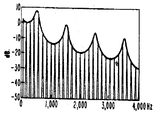
분압기(106)는 차동 증폭기(40)에 의해 개발된 H(S) M 신호의 노치 깊이를 조정하기 위한 장치를 제공한다. 차동증폭기(40)에 인가된 모노신호는 분압기에 의해 분압기의 와이퍼암 설정으로 결정된 양만큼 감쇄된다. 이 방법으로, 차동증폭기(40)에 의해 H(S) 신호로 부터 감산된 차 신호의 진폭이 제어된다. 분압기는 일반적으로 H(S)-M 신호의 노치주파수 700헤르쯔에서 H(S)신호의 그것에 동일한 진폭을 가진 M 신호를 제공하도록 셋트된다. H(S)-M 신호 노치의 깊이 및 그것이 위치되는 주파수는 또한 H(S)신호의 위상에 의해 결정된다. 이것을 제4도에 도시된 제2도 회로의 응답 곡선으로 도시된다. 직렬 쌍 T형 노치 필터들(200 및 220)에 의해 발생된 H(S) 신호 채널의 강도 또는 진폭은 응답곡선(300)에 의해 주파수 함수로서 도시된다. 이 응답곡선(300)은 150 헤르쯔 및 4600 헤르쯔에서 위치된 노치 특성을 가지는 것을 알 수 있다. H(S)-M 신호 채널의 보조 응답곡선(400)은 H(S) 응답곡선(300)의 진폭이 최대인주파수, 대략 700헤르쯔에서 노치되는 것을 알 수 있다.The
오디오주파수 스펙트럼내의 노치위치는 스테레오 음향 합성기가 텔레비젼 수상기와 같은 가시영상과 관련되어 사용될 때 특히 중요하다. 이것은 노치주파수에서의 음향이 별개의 방향 특성을 가지기 때문이며 이 주파수에서 음향은 한 라우드 스피커에서 완전히 재생되고 다른 곳에서 완전히 감쇄된다. 더우기, 진폭의 교차점 대 주파수 응답곡선들(300 및 400)에서의 음향은 두 라우드 스피커의 중감점에 이 음향을 위치시키도록, 양 채널내에 동일한 강도로서 재생될 것이다. 따라서, 노치의 위치는 오디오 주파수 스펙트럼내의 교차점을 형성시킴으로 노치위치는 두 라우드 스피커에 관해 집중되어 음향이 발생될 주파수결정내에 한정된다.Notch position in the audio frequency spectrum is particularly important when a stereo sound synthesizer is used in conjunction with a visible image such as a television receiver. This is because the sound at the notch frequency has distinct directional characteristics, where the sound is completely reproduced in one loudspeaker and completely attenuated in the other. Furthermore, the sound at the intersection point of amplitude versus frequency response curves 300 and 400 will be reproduced with equal intensity in both channels to position this sound at the midpoint of the two loudspeakers. Thus, the position of the notch forms an intersection point in the audio frequency spectrum so that the notch position is confined in the frequency determination where the sound is to be concentrated about the two loudspeakers.
H(S) 신호의 응답곡선(300)이 최대노치깊이의 실제보조 H(S)-M 응답을 발생 시키기 위하여 최대일 때, M신호로서 위상되어지는 H(S)신호가 바람직하다.When the
신호의 위상은 제4도의 기준위상이고 모노 신호 M의 주파수 스펙트럼을 통하는 동안 0°이다. H(S)신호의 위상 응답은 곡선(310)에 의해 표시되고 H(S) 응답곡선(300)의 진폭이 700헤르쯔에서 최대일 때 대략 0°으로 됨을 알 수 있다. 따라서 M 신호는 H(S)신호의 최대 진폭에 동일한 고정 진폭을 가진 제4도의 기준폭으로 사용되므로, 차동증폭기(40)에 의한 H(S) 및 M신호의 감산은 사실상 최대강도의 노치인 700 헤르쯔에서 H(S)-M 신호의 완전한 제거를 초래한다. 차동증폭기(40)에 의한 두 신호의 상호 제거정도는 상기에 검토된 바와 같이 분압기(106)에 의한 M신호 진폭 조정으로 제어된다.The phase of the signal is the reference phase of FIG. 4 and is 0 ° throughout the frequency spectrum of the mono signal M. FIG. It can be seen that the phase response of the H (S) signal is indicated by the curve 310 and becomes approximately 0 ° when the amplitude of the H (S)
H(S) 신호 채널의 위상 응답곡선(310)는 H(S) 신호 채널이 150 헤르쯔 및 4600 헤르쯔의 노치 주파수사이에서 M 신호에 관해 선형으로 감소하는 위상각을 가지는 것을 보여준다. 이 노치 주파수들 부근에서, H(S) 신호는 180° 위상 반전된다. H(S)-M 신호 채널은 유사한 형태로 작용하는 단일 위상응답곡선(410)을 유사하게 가지는 것을 알 수 있다. 더우기, 두 채널의 위상 응답곡선들(310 및 410)은 두 신호가 노치 주파수들간에 대략 90°의 일정한 위상 관계이고 노치주파수에서 순간적으로 위상 내에 있게되거나 또는 위상 밖에 있음을 보여준다.The phase response curve 310 of the H (S) signal channel shows that the H (S) signal channel has a linearly decreasing phase angle with respect to the M signal between the notch frequencies of 150 hertz and 4600 hertz. Near these notch frequencies, the H (S) signal is 180 ° phase inverted. It can be seen that the H (S) -M signal channel similarly has a single
제4도의 위상 및 진폭 응답곡선은 두 라우드스피커들(170 및 172)에 의해 발생된 음향이 스테레오 음향 합성기의 감지분위기를 개발시키는 방법을 도시한다. 라우드스피커 음향신호는 노치 주파수들간에 대체로 일정한 90°로 위상 관계되므로, 이것은 청취자의 귀에 부가적으로 결합(즉 위상내에 있을 경우)되지도 않을 것이며 서로 제거(즉 180° 위상밖에 있을 경우)되지도 않을 것이다. 대신에 라우드 스피커의 응답은 어떤 주파수에서 음향신호를 보강시키거나 또는 제거시키는 경향이 있는 위상의 감쇄없이, 진폭응답곡선들(300 및 400)에 의하여 도시된 바와 사실상 같아질 것이다. 따라서, 감지분위기 효과는 음향주파수 스펙트럼을 지난 라우드 스피커에 의해 발생된 음향 신호진폭의 변화율에 의해 개발됨을 알 수 있다. 두 출력신호의 위상관계는 두 라우드 스피커가 넓게 분리되지 않을 때 즉 텔레비젼 키네스코프의 양 측면상에 위치될 때, 그리 중요하지 않다.The phase and amplitude response curves of FIG. 4 illustrate how the sound generated by the two
더우기, 두 출력신호간의 90° 위상차는 두 라우드 스피커간의 공간을 커버하도록 조정되는 분포음향계를 발생시키는 것으로 알려져왔다. 90°보다 작은 위상차에서, 분포는 협소하고, 90°를 초과한 위상각에서 음향계는 두 라우드 스피커의 전체 180°면을 커버할 때까지의 규격으로 증가된다.Moreover, the 90 ° phase difference between the two output signals has been known to produce distributed acoustics that are adjusted to cover the space between the two loudspeakers. At phase differences smaller than 90 °, the distribution is narrow, and at phase angles above 90 °, the acoustic system is increased to the specification until it covers the entire 180 ° face of both loudspeakers.
이 현상은 이것의 물리적인 한계를 넘지 않는 가시영상을 통하여 방사되는 음향계로서 무비스크린 또는 텔레비젼 키네스코프 같은 스피커간의 전체공간을 차지하는 가시매체와 협동되어 사용 될 때 유리하다.This phenomenon is advantageous when used in conjunction with visible media that occupy the entire space between speakers, such as movie screens or television kinescopes, as an acoustic system that radiates through visible images that do not exceed its physical limits.
물론, 두 채널의 음향 신호는 노치 주파수에 정확하게 위상되고 위상 이탈되며, 따라서 이들 주파수에서 서로 강세되거나 또국 제거되는 경향이 있다. 그러나, 한 음향 신호는 노치 주파수에서 항상 완전히 감쇄되므로, 노치주파수에서 실제상으로는 신호 강세 또는 제거는 없다.Of course, the acoustic signals of the two channels are accurately phased and out of phase at the notch frequencies, and therefore tend to be stressed or de-canalized from each other at these frequencies. However, since one acoustic signal is always completely attenuated at the notch frequency, there is practically no signal stress or cancellation at the notch frequency.
M-H(s) 신호의 위상 응답곡선(420)은 앞서의 수학적으로 논증된 점을 도해적으로 설명한다. 즉H(s)-M신호 대신 H(s)-M신호를 발생시키는 차동증폭기(40)의 입력극성반전은 결과적으로 동일한 합성스테레오효과를 초래할 것이다. 예기된 바와 같이, 진폭응답곡선(400)은 양 차동채널신호에 대해 동일하나, 두 신호의 위상은 180°이상된다.The
M-H(s) 위상응답곡선(420)은 M-H(s)신호 및 H(s) 신호가 노치주파수들 간에 대략 90°로 관련되고 노치 주파수에서 순간적으로 동상(同相)되거나 또는 이상되는 것을 보여준다. 두 차동채널위상응답곡선간의 차이는 M-H(s) 신호가 동일한 양으로 H(s) 신호의 위상을 지연시키는 주파수에서, 대략 90°로 H(s)-M신호가 H(s) 신호를 앞서가는 것이다. 역도 또한 사실이다.The M-H (s)
두 라우드스피커들(170 및 172)은 제3도의 진폭응답선곡들(300 및 400)에 상응하는 음향신호를 발생시키므로, 다른 주파수음향은 두개 사이의 어떤 점이나 또는 다른 라우드스피커에서 발생됨을 알 수 있다. 예를들면, H(s)신호 라우드스피커(170)가 청취자의 좌측에 위치하고 H(s)-M 라우드스피커(172)가 우측에 위치될 경우, 50헤르쯔톤의 음은 우측 라우드스피커에서 우선적으로 재생될 것이고, 700 헤르쯔톤의 음은 좌측라우드스피커로 부터 재생된다. 이들 두 노치 주파수간의 톤은 좌측 및 우측 라우드 스피터 증간위치로 부터 발생되고, 이러한 톤은 두 라우드스피커와 동일한 강도로 재생될 것이므로 320헤르쯔의 음은 두 라운드 스피커간의 증간점에서 발생된다. 합성 스테레오 시스템이 교향악단의 음악이나 군중의 목소리와 같은 다수의 다른 주파수 성분은 가지는 음향 신호를 재생시킬 때, 각 주파수 성분이 다른 방향으로부터 동시에 오는 것 같이 보여서 청취자에세 콘 서트홀 또는 군중의 실제적 분위기를 가진 일층 현실적인 감각이 부여된다.Since the two
앞서 언급한 바와 같이, 본 발명의 스테레오 음향 합성기는 시청자를 위해 가시효과와 더욱 실질적인 원음을 발생시키도록 텔레비젼 수상기와 같은 가시매체와 연합하여 사용된다. 제2도의 스테레오 음향합성기를 사용한 텔레비젼수상기(180)가 제3도에 도시된다. 텔레비젼 키네스코프(182)는 제3도에 도시된 바와 같이, 화면보다 훨씬 커지는 음향계를 방지하도록 키네스코프 측면들에 밀접하게 위치되는 두 라우드 스피커들(170 및 172)사이에 증심이 되어야 한다. 더욱 더 중요한 것은 두 음향채널의 다른 주파수신호의 각각의 강도는 앞거 검토된 기본에 대한 음향 및 영상의 방향 전도혼동을 피하도록 응답곡선들(300 및 400)의 교차주파수와 노치의 적절한 선택을 통해 조심스럽게 제어 되어야만 한다.As mentioned above, the stereo sound synthesizer of the present invention is used in conjunction with a visible medium such as a television receiver to produce a visual effect and more substantial original sound for the viewer. A
전달 함수 필터 노치가 음향 스펙트럼의 동일한 강도의 교차점을 어떻게 적절히 위치시키는가를 이해하기위해, 텔레비젼 프로그래밍 취재 내용을 살피는 것이 필요하다. 텔레비젼 프로그래밍의 대부분은 말하거나 또는 노래하는 각자의 영상을 내포한다. 합성스테레오 시스템은 개개인의 영상의 상대위치결정에 대한방법이 없으므로, 장치는 각자의 영상에 관한 음성위치의 반전 가능성을 배제하도록 방향 등급을 가진 사람음성을 재생시키기 위하여 작동되어서는 안된다.In order to understand how the transfer function filter notch properly positions the intersection of the same intensity in the acoustic spectrum, it is necessary to look at television programming coverage. Most of the TV programming involves video of each one speaking or singing. Since a synthetic stereo system has no method for relative positioning of individual images, the device should not be operated to reproduce human voices with a direction grade to exclude the possibility of inversion of the audio position with respect to each image.
그러므로, 합성 스테레오 장치는 두 라우드 스피커내의 동일한 강도로서 인간 음성을 재생해야만 하고 따라서, 음성은 화면의 중심에서 나와야 할 것이다. 다른 방법으로, 가시방향성을 내장하지 않았거나 또는 조금만 가진음향은 텔레비젼 영상의 여러위치로부터 나오도록 재생될 수 있다. 예를들어, 사무실에서 서로 이야기하는 두 개인을 묘사한 장면을 시청자가 보고있다고 가정하면, 만족할만한 합성스테레오 감각은 두 개인의 음성이 스크린의 중앙에서 발산되고 방송된 영상을 통하여 타자기. 전화기등의 여러배경 잡음이 생길 때 발생될 것이다. 이러한 상태에서, 시청자는 화면의 두 개인이 상대적 위치에 대한 가청 정보를 혼동하여 수신하지 않고 사무실의 감막을 충분히 느낄것이다(모노 재생에 비교할 때).Therefore, the synthesized stereo device must reproduce the human voice at the same intensity in both loudspeakers and therefore the voice will have to come out of the center of the screen. Alternatively, sound that has no built-in visibility or only a few can be reproduced to come from various locations in the television image. For example, assuming a viewer is watching a scene depicting two individuals talking to each other in an office, a satisfactory synthetic stereo sensation is a typewriter through a broadcast image of two individuals' voices radiating from the center of the screen. It will be generated when various background noises such as a telephone are generated. In this state, the viewer will feel enough of the office ambience (compared to mono playback) without the two individuals on the screen confusing and receiving audible information about the relative position.
인간 음성을 화면내에 집중시키기 위해, 가청 주파수 스펙트럼에 관한 언음의 분석을 이해하는 것이 도움이 된다. 제5도는 스테레오 음향합성기의 진폭응답곡선들(300 및 400)의 비교도이고 평균강도대 인간음성의 주파수응답곡선(500)을 도시한다. 곡선(500)으로 도시된 바와 같이, 인간음성은 350 헤르쯔 부근이 피크인 평균강도를 가진다. 이 주파수 이상에서는 음성력은 급격히 떨어진다. 응답곡선 아래에 저음, 중고임 및 고음 노래소리의 주파수 영역이 도시된다. 이 주파수 영역들은, 집중된 음향 감각을 발생시키기 위하여, 두 음향 채널에 의해 발생된 신호의 진폭이 동일해지는 곳에서 320 헤르쯔인 스테레오 합성기의 교차주파수에 대해 대략 집중됨을 아 수 있다. 더우기, 이 320 헤르쯔교 차주파수는 음성 강도 응답곡선(500)의 피크에 매우 가깝다. 그러므로 여기에 도시된 스테레오 합성기는 대부분이 음성력을 평균하여 인간 음성이 발생되는 주파수 부근에서 집중효과를 발생시킬 것이다. 이것은 320 헤르쯔에서 소정의 교차주파수를 발생시키도록 각각 150 및 700 헤르쯔에서 제1 및 제2 노치를 위치시켜 달성된다.In order to focus human speech on the screen, it is helpful to understand speech analysis on the audible frequency spectrum. 5 is a comparison of amplitude response curves 300 and 400 of a stereo sound synthesizer and shows a
인간 음성 형성의 또 다른 이해가 제3노치의 주파수 위치를 분석하는데 필요하다. 언어음은 후두를 통하여 폐로부터 공기를 내어뿜는 데 의해 발생된다. 후두는 성문이라 불리는 개구에 의해 분리되는 성대 또는 두겹의 피부를 포함한다. 상대는 음성의 피치를 정하는 고조파 또는 높은 배음을 가지는 기본 주파수에서 진동한다. 성대 고조파의 진폭은 제6(a)도에 도시된 바와 같이, 옥타브당 약 12데시벨의 비율의 주파수로서 감소한다. 성대진동의 피치는 성대를 조절하는 후두의 근육은 이완시키거나 수축시키는 데 의해 노래하거나 말하는동안 변화된다.Another understanding of human speech formation is needed to analyze the frequency position of the third notch. Speech sounds are produced by blowing air from the lungs through the larynx. The larynx includes vocal cords or two layers of skin separated by an opening called the gate. The opponent vibrates at a fundamental frequency with harmonics or high harmonics that determine the pitch of the voice. The amplitude of the vocal cord harmonics decreases as a frequency at a rate of about 12 decibels per octave, as shown in FIG. 6 (a). The pitch of the vocal cord oscillations changes during singing or speaking by relaxing or contracting the muscles of the larynx that control the vocal cords.
성대에 의해 발생된 음성은 음성관을 구성하는 후두와 함께 인두 및 입을 통해 통과한다. 입술에 대한 후두로 부터의 음성관은 어떤 주파수를 다른 것 보다 적은 정도로 감쇄시키는 공진성 공독으로 작용한다.Voice generated by the vocal cords passes through the pharynx and mouth, along with the larynx, which constitutes the voice tube. The voice tube from the larynx to the lip acts as a resonant reading that attenuates some frequencies to less than others.
음성관은 포르만트(formant)주파수 또는 단순히 포르만트라 불리는 4개 또는 5개의 중요한 공진 주파수를 가진다. 성대 배음(倍音)이 있는 포르만트에 가까울수록 이것은 음성관을 통해 통과함으로 감쇄되고 입술 사이로부터 나올때 이것의 진폭은 더 크다. 포르만트 주파수는 말하는 동안 입술, 턱, 혀 및 후두와 같은 음성 교정기의 위치를 변경시키는 것에 의해서 이동된다. 가수 또는 노련한 연설자는 폐의 기압증가의 필요성 없이 보다 큰 진폭 또는 라우드 니스의 음향을 발생시키도록 그의 피치 주파수와 포르만트주파수를 매우 밀접하게 동시에 이동시키기 위하여 그의 교정기를 변경시켜 이 포르만트 주파수를 이용할 것이다.The speech tube has four or five important resonant frequencies, called formant frequencies or simply formants. The closer to the formant with the vocal cord overtones, the more it is attenuated by passing through the voice tube and its amplitude is greater when coming out between the lips. The formant frequency is shifted by changing the position of the voice braces such as lips, jaw, tongue and larynx while speaking. The singer or seasoned speaker alters his corrector to move his pitch frequency and formant frequency very closely and simultaneously to produce a louder amplitude or loudness sound without the need for increased pressure in the lungs. Will be used.
포르만트 F1, F2, F3등의 주파수 범위로 레벨된다. 개개의 포르만트의 상대적 중요성은 이상의 증가로서 감소된다.It is leveled in the frequency range of the formant F 1 , F 2 , F 3, and the like. The relative importance of the individual formants is reduced by an increase in anomalies.
왜냐하면 고등급의 포르만트 강도는 지수적으로 감쇠되기 때문이다. 제1포르만트 F1은 평균 1000헤르쯔 주파수 범위상의 포르만트 사이의 거리와 250내지 700에르쯔의 영역을 넘는 남성 연설자에 대해 변화한다. 통상적인 남성용 포르만트 패턴이 제6(b)도에 도시된다.) 포르만트 주파수는 음성관 크기의 기능이기 때문에, 여성은 남성보다 큰 평균 포르만트 공간과 높은 포르만트 주파수를 가진다. 성인에 비교된 아이들도 유가한 관계를 가진다.This is because the high formant strength is attenuated exponentially. The first Formant F 1 varies for male speakers over the range of 250 to 700 Hertz and the distance between formants on the average 1000 Hertz frequency range. A typical male formant pattern is shown in Figure 6 (b).) Since the formant frequency is a function of the voice tube size, women have a larger average formant space and higher formant frequency than men. . Children compared to adults also have a similar relationship.
동일한 음향을 발음하는 두 스피커는 일반적으로 그것의 특정한 음성관 크기에 따라 약간 다른 포르만트 주파수를 가진다. 그러나, 특정한 상황에서, 자체의 말의 기본 원리에 집착하는 어떤 스피커는 포르만트 패턴의 철저한 구별에 의해 다른 음향을 발생시키는 것이 항상 기대된다. 따라서, 각각의 이 포르만트 변화가 한번 동일해지고 고려되면, 어떤 스피커의 말과 음향은 주파수 범위상의 상대적 포르만트 위치에의해 동일해질 수 있다. 예를들면, 각각 270 및 2290헤르쯔에 위치된 "히드(heed)"의 제1및 제2포르만트는 제6(c)도에 도시된 음향 스펙트럼내에서 쉽게 동일해질수 있다.Two speakers that pronounce the same sound generally have slightly different formant frequencies, depending on their specific speech tube size. In certain situations, however, some speakers that are obsessed with their basic principles of speech are always expected to produce different sounds by thorough distinction of formant patterns. Thus, once each of these formant changes are equalized and considered, the speaker's words and sounds can be made identical by the relative formant position in the frequency range. For example, the "heed" first and second formants located at 270 and 2290 hertz, respectively, can be easily identified within the acoustic spectrum shown in FIG. 6 (c).
제1세개의 포르만트만이 어떤 특정한 음향을 동일하게 하는데 필요하다는 것은 알려져있고 높은 등급의 포르만트는 개인의 음성특성에 따른 어떤 정보만을 제공한다. F1및 F3는 모음특질의 주요결정체이나 언어의 명료도의 척도를 결정하는 F1및 F3에 대한 F2의 위치이고, 측정은 일반적으로 음의 명료도로서 참조된다. 이것은 그들이 음성화 되기때문에 즉, 그들이 그 형성을 위해 성대진동에 의존되기 때문에 공통언어의 우세한 모음 음향이 자음보다 높은 에너지 함유량을 가지는 사실에 기인된다. 조정에 의하여, 일반적으로 모음 음향(즉, /t/및/p/)의 파열로 특징되는 자음 음향은 그들의 형성(모음형 자음/r/, /m/, /n/, /ng/ 및 /l/을 제외한)에 대한 성대 진동이 요구되지 않고, 그래서 모음에 비해 감소된 큰소리로서 발생된다. 평균하여, 비음성화된 자음은 모음 음향보다 20데시벨 약하다. 약한 자음음향을 판별하기 위한 청취자의 능력이 언어의 명료도측정의 중요한 결정요소임은 알려져 있다.It is known that only the first three formants are needed to equalize a particular sound and the higher grade formants only provide certain information according to the individual's voice characteristics. F 1 and F 3 are the positions of F 2 relative to F 1 and F 3 , which determine a measure of the clarity of the vowel features or language clarity, and measurements are generally referred to as negative intelligibility. This is due to the fact that the prevailing vowel sound of the common language has a higher energy content than the consonants because they are vocalized, that is, they are dependent on the vocal cord oscillations for their formation. By adjustment, consonant sounds generally characterized by the rupture of vowel sounds (ie / t / and / p /) are characterized by their formation (vowel consonants / r /, / m /, / n /, / ng / and / vocal cord vibration is not required (except l /), so it is generated as a reduced loudness compared to vowels. On average, unvoiced consonants are 20 decibels less than vowel sounds. It is known that the listener's ability to discriminate weak consonants is an important determinant of language intelligibility.
모음 과같게 자음이 그 자체의 특정한 포르만트 주파수를 가지는 동안, 자음의 포르만트는 독립적으로 명료도를 좌우하지는 않는다. 자음의 특질은 언어음향의 "허브(hub)"라 불리는 모음의 제2포르만트상의 이것의 효과에 의해 특징되는 것으로서 이것이 연합되는 모음 또는 모음들상의 이것의 효과에 의해 결정된다.While consonants, like vowels, have their own specific formant frequency, the formants of consonants do not independently influence clarity. The quality of the consonant is characterized by its effect on the second formant of the vowel, called the "hub" of verbal sound, which is determined by its effect on the vowel or vowels to which it is associated.
일반적으로, 모음 전후의 자음은 연속적인 자음의 허브를 향하거나 또는 선행된 자음의 "궤적" F2또는 허브로부터 떨어져 모음의 제2포르만트가 발생하도록 한다. 이것은 그 자음의 동일성에 대한 핵심적인 단서를 주는 자음 전후의 모음의 제2포르만트의 변화동작이다.Generally, the consonants before and after the vowels cause the second formant of the vowels to be directed towards the hub of the continuous consonant or away from the "trajectory" F 2 or hub of the preceding consonant. This is the changing behavior of the second formant of the vowels before and after the consonants, giving a key clue to the identity of the consonants.
그러므로, 본 발명의 스테레오 음향합성기가 집중되고 명확하게 명료한 언어 음향을 제공할 경우, 언어음의 포르만트주파수는 두 라우드 스피커 채널내의 동일한 강도로 제공되는 것이 바람직하다는 것을 알 수 있다. 제7도는 700헤르쯔에서의 중간 노치위치 및 4600헤르쯔에서의 상부노치주파수의 위치가 대략 1680헤르쯔에서 동일한 라우드 스피커신호 진폭의 교차를 제공하는 것을 도시한다.Therefore, it can be seen that when the stereophonic synthesizer of the present invention provides a concentrated and clearly clear language sound, the formant frequency of the language sound is preferably provided at the same intensity in both loudspeaker channels. 7 shows that the intermediate notch position at 700 Hz and the upper notch frequency at 4600 Hz provide the intersection of the same loudspeaker signal amplitude at approximately 1680 Hz.
이들 라우드 스피커 채널 응답곡선 아래에 열개의 대부분 공통 모음 음향에 대한 제1세 르만트의 위치가 구획된다. 도시된 포르만트 주파수들은 남성, 여성 및 아이들에 대한 평균 값이다, 560헤르쯔의 중간 값으로 270헤르쯔내지 1050헤르쯔의 제1포르만트 값 영역을 화살표에 의해 설계된다. 두 라우드 스피커 채널의 응답곡선이 이 중간 값에서 대략 12데시벨의 강도 차이를 가질지라도, 320헤르쯔에서의 낮은 교차주파수는 인간음성의 피치주파수와 인간 음성의 강도 분포 및 제1포르만트주파수의 영역들 사이에 구성됨을 기억해야만 한다.Below these loudspeaker channel response curves, the location of the first Sermant for the ten most common vowel sounds is partitioned. The formant frequencies shown are average values for males, females, and children, designed by arrows in the first formant value region of 270 Hz to 1050 Hz with a median of 560 Hz. Although the response curves of the two loudspeaker channels have an intensity difference of approximately 12 decibels at this intermediate value, the low crossover frequency at 320 Hz results in a pitch range of human speech, an intensity distribution of human speech, and a region of the first formant frequency. Remember to be configured between them.
피치 주파수는 일반적으로 저음을 위해 90헤르쯔로 상하하는 제1포르만트 주파수보다 낮기 때문에 음성 강도 곡선(500)이 중간 주파수에서 평균 피치 및 제1포르만트 주파수를 피크로 해야되는 것은 놀라운 일이 아니다. 320헤르쯔의 낮은 교차 주파수는 인간음성의 피치주파수와 인간 음성의 강도 분포 및 제1포르만트주파수의 영역들 사이에 구성됨을 기억해야만 한다.Since the pitch frequency is generally lower than the first formant frequency up and down to 90 hertz for bass, it is surprising that the
피치 주파수는 일반적으로 저음을 위해 90헤르쯔르 강하하는 제1포르만트 주파수보다 낮기 때문에 음성 강도 곡선(500)이 중간 주파수에서 평균 피치 및 제1포르만트 주파수를 피크로 해야되는 것은 놀라운 일이 아니다. 320헤르쯔의 낮은 교차 주파수는 음성 강도 응답곡선(500)의 피크에 밀접하게 관련되기 때문에 만족스럽다.Since the pitch frequency is generally lower than the first formant frequency dropping 90 Hz for bass, it is surprising that the
제7도는 850헤르쯔에서 3200헤르쯔로 분포되는 제2포르만트 주파수와 1680헤르쯔에서 3500헤르쯔변하는 제3포르만트 주파수를 도시한다. 제2포르만트 진폭은 제1포르만트의 평균 이하인 평균 12데시벨이고, 제3포르만트는 제1포르만트의 그것이하이고 26데시벨 이상의 평균진폭을 가진다. 제2 및 제3포르만트에 대한 중간 주파수는 각각 화살표 F2및 F3로 표시된다. 두 라우드 스피커의 강도 레벨은 제3포르만트 F3의 중간값에서 대략 5데시벨 떨어지고 중요한 허브포르만트 F3의 중간값은 두 라우드 스피커채널의 동일한 강도 교차점에서 거의 정확함을 알 수 있다. 따라서, 제5포르만트는 평균하여 양 스피커에 의해 동일한 강도로 발생될 것이다. 그렇게 재생된 음성 음향은 텔레비젼 영상에 관해 집중될 것이고 명료성이 나아질 것이다.7 shows a second formant frequency ranging from 850 hertz to 3200 hertz and a third formant frequency varying from 1680 hertz to 3500 hertz. The second formant amplitude is an average of 12 decibels below the average of the first formant, and the third formant is below that of the first formant and has an average amplitude of 26 decibels or more. The intermediate frequencies for the second and third formants are indicated by arrows F 2 and F 3 , respectively. It can be seen that the intensity level of the two loudspeakers is approximately 5 decibels away from the median of the third formant F 3, and the median of the important hub formant F 3 is nearly accurate at the same intensity intersection of the two loudspeaker channels. Thus, the fifth formant will be generated with the same intensity by both speakers on average. The audio sound so reproduced will be focused on the television image and the clarity will be better.
앞서의 사무실에서 두 스피커의 실시예를 다시보면, 상술된 점에서 본 발명의 스테레오 음향합성기는 스피커의 음성이 텔레비젼 영상의 중앙에서 나오는 효과를 발생시키는 것을 알수 있다. 사무실 환경에서 일어나는 배경 잡음은 대략 30헤르쯔에서 16000헤르쯔로 분포되는 음향 스펙트럼상에 명료하게 임의로 분포된다. 이 배경음향은 방송된 영상을 통하는 동안 사무실 음향이 발생되는 것으로서 별개의 분위기 효과를 만들도록 제4도의 응답속선들(300 및 400)에 의한 변화 비율로 라우드 스피커에 의해 재생될 것이다. 유쾌한 시청은 단지 외부 관측자 대신에, 사무실 부분의 증가된 화면 감각을 텔레비젼 시청자가 획득하므로, 증가된다.Looking back at the embodiment of the two speakers in the office above, it can be seen from the above that the stereoacoustic synthesizer of the present invention produces the effect of the speaker's voice coming out of the center of the television image. Background noise in an office environment is clearly randomly distributed over an acoustic spectrum ranging from approximately 30 hertz to 16000 hertz. This background sound will be reproduced by the loudspeaker at the rate of change by the
Claims (1)
Applications Claiming Priority (2)
| Application Number | Priority Date | Filing Date | Title |
|---|---|---|---|
| US06/018,905 US4239939A (en) | 1979-03-09 | 1979-03-09 | Stereophonic sound synthesizer |
| US18,905 | 1979-03-09 |
Publications (1)
| Publication Number | Publication Date |
|---|---|
| KR830000937B1 true KR830000937B1 (en) | 1983-05-11 |
Family
ID=21790357
Family Applications (1)
| Application Number | Title | Priority Date | Filing Date |
|---|---|---|---|
| KR1019800000965A KR830000937B1 (en) | 1979-03-09 | 1980-03-08 | Stereo sound synthesizer |
Country Status (6)
| Country | Link |
|---|---|
| US (1) | US4239939A (en) |
| EP (1) | EP0015770A1 (en) |
| JP (1) | JPS55123300A (en) |
| KR (1) | KR830000937B1 (en) |
| CA (1) | CA1135839A (en) |
| DK (1) | DK156361C (en) |
Families Citing this family (28)
| Publication number | Priority date | Publication date | Assignee | Title |
|---|---|---|---|---|
| US4449229A (en) * | 1980-10-24 | 1984-05-15 | Pioneer Electronic Corporation | Signal processing circuit |
| US4394535A (en) * | 1981-03-09 | 1983-07-19 | Rca Corporation | Split phase stereophonic sound synthesizer |
| IT1209458B (en) * | 1981-05-08 | 1989-08-30 | Rca Corp | SWITCHING COMPLEX FOR A STEREOFONIC AUDIO SYNTHESIZER. |
| US4479235A (en) * | 1981-05-08 | 1984-10-23 | Rca Corporation | Switching arrangement for a stereophonic sound synthesizer |
| GB2134358A (en) * | 1982-07-22 | 1984-08-08 | Tvi Systems Ltd | Monaural to binaural audio processor |
| US4555795A (en) * | 1982-07-22 | 1985-11-26 | Tvi Systems, Ltd. | Monaural to binaural audio processor |
| US4517602A (en) * | 1982-10-18 | 1985-05-14 | Rca Corporation | Dynamic noise filter for an audio signal in a television |
| US4653096A (en) * | 1984-03-16 | 1987-03-24 | Nippon Gakki Seizo Kabushiki Kaisha | Device for forming a simulated stereophonic sound field |
| US4748669A (en) * | 1986-03-27 | 1988-05-31 | Hughes Aircraft Company | Stereo enhancement system |
| US4783814A (en) * | 1986-10-09 | 1988-11-08 | Comprehensive Health Care Corp. Of America | Stethoscope having pseudostereophonic binaural enhancement |
| US4739514A (en) * | 1986-12-22 | 1988-04-19 | Bose Corporation | Automatic dynamic equalizing |
| JP2610139B2 (en) * | 1987-09-05 | 1997-05-14 | ヤマハ株式会社 | Tone generator |
| US4841572A (en) * | 1988-03-14 | 1989-06-20 | Hughes Aircraft Company | Stereo synthesizer |
| US5274708A (en) * | 1992-06-01 | 1993-12-28 | Fusan Labs, Inc. | Digital stereo sound enhancement unit and method |
| JP2886402B2 (en) * | 1992-12-22 | 1999-04-26 | 株式会社河合楽器製作所 | Stereo signal generator |
| KR0120086Y1 (en) * | 1993-08-31 | 1998-07-15 | 김광호 | Sound converting circuits |
| US5661808A (en) | 1995-04-27 | 1997-08-26 | Srs Labs, Inc. | Stereo enhancement system |
| US5692050A (en) * | 1995-06-15 | 1997-11-25 | Binaura Corporation | Method and apparatus for spatially enhancing stereo and monophonic signals |
| US6590983B1 (en) * | 1998-10-13 | 2003-07-08 | Srs Labs, Inc. | Apparatus and method for synthesizing pseudo-stereophonic outputs from a monophonic input |
| US7260231B1 (en) * | 1999-05-26 | 2007-08-21 | Donald Scott Wedge | Multi-channel audio panel |
| US7031474B1 (en) | 1999-10-04 | 2006-04-18 | Srs Labs, Inc. | Acoustic correction apparatus |
| US7277767B2 (en) | 1999-12-10 | 2007-10-02 | Srs Labs, Inc. | System and method for enhanced streaming audio |
| US7016509B1 (en) | 2000-09-08 | 2006-03-21 | Harman International Industries, Inc. | System and method for varying low audio frequencies inversely with audio signal level |
| US7522733B2 (en) * | 2003-12-12 | 2009-04-21 | Srs Labs, Inc. | Systems and methods of spatial image enhancement of a sound source |
| JP5063528B2 (en) * | 2008-08-21 | 2012-10-31 | 株式会社オーディオテクニカ | Noise cancellation system |
| JP2014168228A (en) * | 2013-01-30 | 2014-09-11 | Yamaha Corp | Sound emission device |
| WO2014190140A1 (en) | 2013-05-23 | 2014-11-27 | Alan Kraemer | Headphone audio enhancement system |
| FI20195726A1 (en) * | 2019-09-02 | 2021-03-03 | Genelec Oy | System and method for complementary audio output |
Family Cites Families (5)
| Publication number | Priority date | Publication date | Assignee | Title |
|---|---|---|---|---|
| US2616970A (en) * | 1948-02-11 | 1952-11-04 | Hartford Nat Bank & Trust Co | Device for the transmission by electrical means of oscillations of acoustic frequency |
| DE944799C (en) * | 1954-10-23 | 1956-06-21 | Nordwestdeutscher Rundfunk | Arrangement for single-channel stereophony |
| US3056854A (en) * | 1957-11-27 | 1962-10-02 | Unitronics Corp | Binaural sound system for television receivers |
| US3670106A (en) * | 1970-04-06 | 1972-06-13 | Parasound Inc | Stereo synthesizer |
| US4137510A (en) * | 1976-01-22 | 1979-01-30 | Victor Company Of Japan, Ltd. | Frequency band dividing filter |
-
1979
- 1979-03-09 US US06/018,905 patent/US4239939A/en not_active Expired - Lifetime
-
1980
- 1980-02-28 CA CA000346611A patent/CA1135839A/en not_active Expired
- 1980-03-05 JP JP2857180A patent/JPS55123300A/en active Granted
- 1980-03-07 DK DK100380A patent/DK156361C/en not_active IP Right Cessation
- 1980-03-07 EP EP80300723A patent/EP0015770A1/en not_active Ceased
- 1980-03-08 KR KR1019800000965A patent/KR830000937B1/en active
Also Published As
| Publication number | Publication date |
|---|---|
| DK156361B (en) | 1989-08-07 |
| DK100380A (en) | 1980-09-10 |
| US4239939A (en) | 1980-12-16 |
| DK156361C (en) | 1989-12-27 |
| JPH0136320B2 (en) | 1989-07-31 |
| EP0015770A1 (en) | 1980-09-17 |
| JPS55123300A (en) | 1980-09-22 |
| CA1135839A (en) | 1982-11-16 |
Similar Documents
| Publication | Publication Date | Title |
|---|---|---|
| KR830000937B1 (en) | Stereo sound synthesizer | |
| US6590983B1 (en) | Apparatus and method for synthesizing pseudo-stereophonic outputs from a monophonic input | |
| US5043970A (en) | Sound system with source material and surround timbre response correction, specified front and surround loudspeaker directionality, and multi-loudspeaker surround | |
| KR100433642B1 (en) | Stereo enhancement system | |
| US4748669A (en) | Stereo enhancement system | |
| Snow | Basic principles of stereophonic sound | |
| US4356349A (en) | Acoustic image enhancing method and apparatus | |
| US5222059A (en) | Surround-sound system with motion picture soundtrack timbre correction, surround sound channel timbre correction, defined loudspeaker directionality, and reduced comb-filter effects | |
| JPS63183495A (en) | Sound field controller | |
| US5119422A (en) | Optimal sonic separator and multi-channel forward imaging system | |
| US6850622B2 (en) | Sound field correction circuit | |
| Snow | Basic principles of stereophonic sound | |
| JP2001509976A (en) | Recording and playback two-channel system for providing holophonic reproduction of sound | |
| Jecklin | A different way to record classical music | |
| JPH06269096A (en) | Sound image controller | |
| US4394535A (en) | Split phase stereophonic sound synthesizer | |
| JP2000059897A (en) | Sound reproduction device and sound reproduction method | |
| US20010037194A1 (en) | Audio signal processing device | |
| US3940560A (en) | Quadriphonic sound pick-up and reproduction devices | |
| JPH0724440B2 (en) | Audio signal transmission system | |
| US5539833A (en) | Audio signal amplifier device | |
| EP0323830B1 (en) | Surround-sound system | |
| Olson et al. | On the realistic reproduction of sound with particular reference to sound motion pictures | |
| Gerzon | Surround-sound from 2-channel stereo | |
| Hietala | Perceived differences in recordings produced with four 5.0 surround microphone techniques |