KR20230077721A - Composite Light Guide Optical Elements - Google Patents
Composite Light Guide Optical Elements Download PDFInfo
- Publication number
- KR20230077721A KR20230077721A KR1020237007989A KR20237007989A KR20230077721A KR 20230077721 A KR20230077721 A KR 20230077721A KR 1020237007989 A KR1020237007989 A KR 1020237007989A KR 20237007989 A KR20237007989 A KR 20237007989A KR 20230077721 A KR20230077721 A KR 20230077721A
- Authority
- KR
- South Korea
- Prior art keywords
- image
- loe
- coupling
- major outer
- optical system
- Prior art date
Links
- 230000003287 optical effect Effects 0.000 title claims abstract description 50
- 239000002131 composite material Substances 0.000 title 1
- 230000008878 coupling Effects 0.000 claims abstract description 25
- 238000010168 coupling process Methods 0.000 claims abstract description 25
- 238000005859 coupling reaction Methods 0.000 claims abstract description 25
- 230000021615 conjugation Effects 0.000 claims abstract description 7
- 238000000576 coating method Methods 0.000 claims description 8
- 239000000853 adhesive Substances 0.000 claims description 6
- 230000001070 adhesive effect Effects 0.000 claims description 6
- 239000012780 transparent material Substances 0.000 claims description 3
- 238000000034 method Methods 0.000 claims 1
- 238000005286 illumination Methods 0.000 description 15
- 239000000758 substrate Substances 0.000 description 6
- 238000010586 diagram Methods 0.000 description 4
- 239000011248 coating agent Substances 0.000 description 3
- 238000002347 injection Methods 0.000 description 3
- 239000007924 injection Substances 0.000 description 3
- 238000004519 manufacturing process Methods 0.000 description 3
- 230000001902 propagating effect Effects 0.000 description 3
- 230000000712 assembly Effects 0.000 description 1
- 238000000429 assembly Methods 0.000 description 1
- 230000003190 augmentative effect Effects 0.000 description 1
- 230000000295 complement effect Effects 0.000 description 1
- 238000010276 construction Methods 0.000 description 1
- 210000005069 ears Anatomy 0.000 description 1
- 210000003128 head Anatomy 0.000 description 1
- 238000000265 homogenisation Methods 0.000 description 1
- 230000003116 impacting effect Effects 0.000 description 1
- 230000010354 integration Effects 0.000 description 1
- 239000000463 material Substances 0.000 description 1
- 230000007246 mechanism Effects 0.000 description 1
- 230000000644 propagated effect Effects 0.000 description 1
- 238000002310 reflectometry Methods 0.000 description 1
- 238000000926 separation method Methods 0.000 description 1
- 239000000243 solution Substances 0.000 description 1
Images


Classifications
-
- G—PHYSICS
- G02—OPTICS
- G02B—OPTICAL ELEMENTS, SYSTEMS OR APPARATUS
- G02B27/00—Optical systems or apparatus not provided for by any of the groups G02B1/00 - G02B26/00, G02B30/00
- G02B27/01—Head-up displays
- G02B27/017—Head mounted
- G02B27/0172—Head mounted characterised by optical features
-
- G—PHYSICS
- G02—OPTICS
- G02B—OPTICAL ELEMENTS, SYSTEMS OR APPARATUS
- G02B27/00—Optical systems or apparatus not provided for by any of the groups G02B1/00 - G02B26/00, G02B30/00
- G02B27/10—Beam splitting or combining systems
- G02B27/12—Beam splitting or combining systems operating by refraction only
- G02B27/126—The splitting element being a prism or prismatic array, including systems based on total internal reflection
-
- G—PHYSICS
- G02—OPTICS
- G02B—OPTICAL ELEMENTS, SYSTEMS OR APPARATUS
- G02B27/00—Optical systems or apparatus not provided for by any of the groups G02B1/00 - G02B26/00, G02B30/00
- G02B27/28—Optical systems or apparatus not provided for by any of the groups G02B1/00 - G02B26/00, G02B30/00 for polarising
- G02B27/283—Optical systems or apparatus not provided for by any of the groups G02B1/00 - G02B26/00, G02B30/00 for polarising used for beam splitting or combining
-
- G—PHYSICS
- G02—OPTICS
- G02B—OPTICAL ELEMENTS, SYSTEMS OR APPARATUS
- G02B6/00—Light guides; Structural details of arrangements comprising light guides and other optical elements, e.g. couplings
- G02B6/0001—Light guides; Structural details of arrangements comprising light guides and other optical elements, e.g. couplings specially adapted for lighting devices or systems
- G02B6/0011—Light guides; Structural details of arrangements comprising light guides and other optical elements, e.g. couplings specially adapted for lighting devices or systems the light guides being planar or of plate-like form
- G02B6/0013—Means for improving the coupling-in of light from the light source into the light guide
-
- G—PHYSICS
- G02—OPTICS
- G02B—OPTICAL ELEMENTS, SYSTEMS OR APPARATUS
- G02B6/00—Light guides; Structural details of arrangements comprising light guides and other optical elements, e.g. couplings
- G02B6/0001—Light guides; Structural details of arrangements comprising light guides and other optical elements, e.g. couplings specially adapted for lighting devices or systems
- G02B6/0011—Light guides; Structural details of arrangements comprising light guides and other optical elements, e.g. couplings specially adapted for lighting devices or systems the light guides being planar or of plate-like form
- G02B6/0033—Means for improving the coupling-out of light from the light guide
-
- G—PHYSICS
- G02—OPTICS
- G02B—OPTICAL ELEMENTS, SYSTEMS OR APPARATUS
- G02B27/00—Optical systems or apparatus not provided for by any of the groups G02B1/00 - G02B26/00, G02B30/00
- G02B27/01—Head-up displays
- G02B27/017—Head mounted
- G02B2027/0178—Eyeglass type
Landscapes
- Physics & Mathematics (AREA)
- General Physics & Mathematics (AREA)
- Optics & Photonics (AREA)
- Optical Couplings Of Light Guides (AREA)
Abstract
시청을 위해 이미지를 사용자를 향해 지향시키기 위한 광학 시스템(100)은, 내부 반사에 의한 이미지의 전파를 지원하기 위한 평행한 주 외부 표면들(11a, 11b)을 갖는 광 가이드 광학 요소(light-guide optical element, LOE)(10), 사용자의 눈을 향해 이미지를 커플링 아웃하기 위한 커플링 아웃 배열체, 및 커플링 인 애퍼처를 포함한다. 이미지 투영기(114)는 이미지를 생성하기 위한 이미지 생성기(32), 이미지를 시준하기 위한 시준 광학계(31), 및 이미지 공액 생성기(20, 33, 34)를 포함한다. 이미지 투영기는 시준된 이미지와 그 공액 이미지가 주 외부 표면들 중 어느 하나에 충돌하기 전에 이미지들 둘 모두를 LOE 내로 도입하기 위해 커플링 인 애퍼처에 커플링된다. 이미지 공액 생성기는 제2 이미지 생성기(33)일 수 있거나, LOE의 주 외부 표면들과 연접하지 않은 하나 이상의 반사 표면(22, 23, 24, 34)을 채용할 수 있다.An optical system (100) for directing an image towards a user for viewing includes a light-guide optical element (light-guide) having parallel major outer surfaces (11a, 11b) for assisting propagation of the image by internal reflection. optical element (LOE) 10, a coupling out arrangement for coupling out the image towards the user's eye, and a coupling in aperture. The image projector 114 includes an image generator 32 for generating an image, collimation optics 31 for collimating the image, and image conjugate generators 20, 33 and 34. An image projector is coupled to the coupling-in aperture to introduce both the images into the LOE before the collimated image and its conjugate image impinge on either of the major outer surfaces. The image conjugation generator may be the second image generator 33 or may employ one or more reflective surfaces 22, 23, 24, 34 that do not abut the major exterior surfaces of the LOE.

Description
본 발명은 광학 시스템에 관한 것으로, 특히 사용자에게 이미지를 디스플레이하기 위한 광학 시스템에 관련된다.The present invention relates to optical systems, and more particularly to optical systems for displaying images to a user.
다양한 유형의 디스플레이, 특히 근안 디스플레이(near-eye display, NED)는 전형적으로 이미지가 이미지 투영기로부터 주입되어 내부 전반사(total internal reflection, TIR)에 의해 도파관 내에서 전파되고, 후속하여 하나 이상의 커플링 아웃 요소(coupling-out element)(예를 들어, 부분적으로 반사하는 내부 표면("패싯(facet)"), 회절 격자 등)를 통해 관찰자의 눈을 향해 커플링 아웃되는 하나 이상의 도파관을 채용한다. 그러한 도파관은 도파관의 길이를 따라 연장되는 한 쌍의 평행한 주 외부 표면을 갖는 투명 기판으로 제조되며, 이들 사이에서 이미지 및 그 공액이 반사된다. 이미지는 바람직하게는 시준 이미지이고, 도파관은 바람직하게는 평면이다. 최상의 성능을 위해, 이미지 및 그 공액 둘 모두가 도파관을 완전히 채워야 하며, 이에 따라 이미지의 각 픽셀 및 공액 이미지의 각 픽셀에 대응하는 조명이(사용자의 눈에 도달할 수 있는 출력 이미지에 기여하는 도파관의 영역들에 대해) 도파관의 두께 내의 모든 지점에 존재한다.Various types of displays, particularly near-eye displays (NEDs), typically have an image injected from an image projector and propagated within a waveguide by total internal reflection (TIR), followed by one or more coupling outs. It employs one or more waveguides that are coupled out through a coupling-out element (eg, a partially reflective inner surface ("facet"), a diffraction grating, etc.) towards the eye of the observer. Such a waveguide is made of a transparent substrate having a pair of parallel major outer surfaces extending along the length of the waveguide between which the image and its conjugate are reflected. The image is preferably a collimated image and the waveguide is preferably planar. For best performance, both the image and its conjugate should completely fill the waveguide, so that each pixel in the image and the light corresponding to each pixel in the conjugate image (the waveguide contributing to the output image that can reach the user's eyes) for regions of) at every point within the thickness of the waveguide.
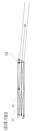
도파관의 충전은 주입된 이미지의 주 광선에 대략 수직으로 배향되는 커플링 인 표면을 갖는 커플링 인 프리즘을 제공함으로써 달성될 수 있으며, 공액 이미지를 생성하기 위해 이미지가 도파관의 일 표면의 연장된 영역 상에 있게 한다. 그러나, 특히 주 외부 표면들에 대해 비교적 얕은 각도로(즉, 표면의 법선에 대해 90도에 가깝게) 주입된 이미지들을 갖는 구현예들에 대해, 공액 이미지로 도파관을 채우는데 요구되는 커플링 인 영역의 길이는 도파관의 치수들에 상당히 부가된다. 이는 도파관(10)에 대한 전형적인 커플링을 도시하는 도 2a에 도시된다. 도파관 기판으로부터 절단되거나 도파관 기판에 부착된 커플링 인 프리즘(14)은 광선(40, 41)을 도파관 내로 얕은 각도로 지향시키기 위해 사용된다. 광선(40, 41)이 도파관 내에서 전파됨에 따라, 광선(41)은 도파관의 상부 표면에서 반사되어 광선(40)의 공액이 된다. 도 1로부터 명백한 바와 같이, 커플링 인 프리즘으로도, 도파관 내에 얕은 광선의 공액을 생성하기 위해 비교적 큰 입력 애퍼처(및 결과적으로 더 큰 투영기)가 요구된다.Filling of the waveguide may be accomplished by providing a coupling-in prism having a coupling-in surface oriented approximately perpendicular to the chief ray of the injected image, wherein the image is formed over an extended area of one surface of the waveguide to create a conjugated image. put on top However, especially for implementations with images implanted at relatively shallow angles to the major outer surfaces (i.e. close to 90 degrees relative to the surface's normal), the coupling-in region required to fill the waveguide with the conjugate image The length of λ adds significantly to the dimensions of the waveguide. This is shown in FIG. 2A which shows a typical coupling for
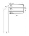
도 2b에 예시된 도파관을 충전하기 위한 대안적인 접근법은 주 외부 표면들 사이의 도파관의 두께를 세분하고 외부 표면들에 평행한 도파관의 길이를 따른 경로의 적어도 일부로 연장되는 대략 중간점에서 도파관(10) 내에 내부적으로 50% 빔 스플리터(또는 "혼합기")(13)를 이용한다. 빔 스플리터는 도 2a에 도시된 바와 같이, 광선을 부분적으로 반사하여 도파관 내에서 광선의 공액(예를 들어, 광선(41))을 생성하는 데 효과적이고, 더 작은 입력 애퍼처 및 웨지 프리즘(14)을 허용한다.An alternative approach to filling the waveguide illustrated in FIG. 2B is to subdivide the thickness of the waveguide between its major outer surfaces and to extend the waveguide (10 ) using a 50% beam splitter (or “mixer”) 13 internally in A beam splitter is effective to partially reflect light rays to create a conjugation of light rays (e.g., light ray 41) within a waveguide, as shown in FIG. 2A, with a smaller input aperture and wedge prism 14. ) is allowed.
혼합기(13)의 존재는 더 작은 투영기 애퍼처 및 커플링 프리즘의 사용을 허용하지만, 혼합기 자체는 도파관의 치수에 상당히 부가된다. 혼합기(13)에 요구되는 최소 길이는 식 ![]()
![]()
본 발명은 시청을 위해 이미지를 사용자를 향해 지향시키기 위한 광학 시스템이다.The present invention is an optical system for directing an image towards a user for viewing.
본 발명의 실시예의 교시에 따르면, 시청을 위해 이미지를 사용자를 향해 지향시키기 위한 광학 시스템이 제공되며, 광학 시스템은: (a) 투명한 물질로 형성되고, 상호 평행한 제1 주 외부 표면과 제2 주 외부 표면에서의 내부 반사에 의한 이미지의 전파를 지원하기 위한 제1 주 외부 표면 및 제2 주 외부 표면을 갖는 광 가이드 광학 요소(light-guide optical element, LOE) ― LOE는 이미지를 사용자의 눈을 향해 커플링 아웃(coupling out)하기 위한 커플링 아웃 배열체를 가지며, LOE는 커플링 인 애퍼처를 가짐 ―; (b) 이미지를 생성하기 위한 이미지 생성기, 이미지를 시준하기 위한 시준 광학계, 및 이미지 공액 생성기를 포함하는 이미지 투영기 ― 이미지 투영기는 시준 이미지와 그 공액 이미지가 제1 주 외부 표면 또는 제2 주 외부 표면 중 어느 하나에 충돌하기 전에, 커플링 인 애퍼처 내로 시준 이미지와 공액 이미지를 도입하기 위해 커플링 인 애퍼처에 커플링됨 ― 를 포함한다.According to the teachings of embodiments of the present invention, there is provided an optical system for directing an image towards a user for viewing, the optical system comprising: (a) a first major outer surface and a second mutually parallel first major outer surface formed of a transparent material; A light-guide optical element (LOE) having a first major outer surface and a second major outer surface for supporting propagation of an image by internal reflection at the major outer surface - the LOE is capable of directing an image to a user's eye has a coupling out arrangement for coupling out toward the LOE, and the LOE has a coupling in aperture; (b) an image projector comprising an image generator for generating an image, collimating optics for collimating the image, and an image conjugate generator, the image projector wherein the collimated image and the conjugate image are projected onto a first major outer surface or a second major outer surface coupled to the coupling-in aperture to introduce the collimated image and the conjugate image into the coupling-in aperture before impinging on either one.
본 발명의 실시예의 추가 특징에 따르면, 이미지 공액 생성기는 제2 이미지 생성기를 포함한다.According to a further feature of an embodiment of the invention, the image conjugate generator includes a second image generator.
본 발명의 실시예의 추가 특징에 따르면, 이미지 공액 생성기는 제1 주 외부 표면 및 상 제2 주 외부 표면과 연접하지 않은 적어도 하나의 반사면을 포함한다.According to a further feature of an embodiment of the present invention, the image conjugate generator includes at least one reflective surface not contiguous with the first major outer surface and the second major outer surface.
본 발명의 실시예의 추가 특징에 따르면, 이미지 공액 생성기는 제1 주 외부 표면 및 상 제2 주 외부 표면과 평행하지 않은 적어도 하나의 반사면을 포함한다.According to a further feature of an embodiment of the present invention, the image conjugate generator includes at least one reflective surface non-parallel to the first major outer surface and the second major outer surface.
본 발명의 실시예의 추가 특징에 따르면, 이미지 공액 생성기는 두 개의 반사 표면들 사이에, 그리고 두 개의 반사 표면들에 평행하게, 배치된 적어도 하나의 빔 스플리터를 포함하는 빔 증배기를 포함한다.According to a further feature of an embodiment of the invention, the image conjugate generator includes a beam multiplier comprising at least one beam splitter disposed between and parallel to the two reflective surfaces.
본 발명의 실시예의 추가 특징에 따르면, 빔 증배기는 반사 표면들 중 적어도 세 개 사이에 개재된 빔 스플리터들 중 적어도 두 개를 포함한다.According to a further feature of an embodiment of the present invention, the beam multiplier includes at least two of the beam splitters sandwiched between at least three of the reflective surfaces.
본 발명의 실시예의 추가 특징에 따르면, 빔 증배기는 LOE의 두께와 상이한 외부 두께를 갖는다.According to a further feature of an embodiment of the present invention, the beam multiplier has an external thickness different from the thickness of the LOE.
본 발명의 실시예의 추가 특징에 따르면, 빔 증배기의 반사 표면들은 층상 구조의 층들 사이의 계면에서의 반사 표면들이고, 층상 구조의 외부 표면들은 광 증배기의 광학적 비기능 표면들이다.According to a further feature of an embodiment of the present invention, the reflective surfaces of the beam multiplier are reflective surfaces at interfaces between the layers of the layered structure, and the outer surfaces of the layered structure are optically non-functional surfaces of the light multiplier.
본 발명의 실시예의 추가 특징에 따르면, LOE는 제1 주 외부 표면 및 제2 주 외부 표면에 대해 경사지게 배치된 커플링 인 반사기를 더 포함하며, 커플링 인 반사기는 시준된 이미지를 제1 주 외부 표면에 충돌하고 공액 이미지를 제2 주 외부 표면에 충돌하게 재지향시키도록 배치된다.According to a further feature of an embodiment of the present invention, the LOE further comprises a coupling-in reflector disposed at an angle with respect to the first major outer surface and the second major outer surface, the coupling-in reflector transmitting the collimated image to the first major outer surface. It is arranged to impinge on the surface and redirect the conjugate image to impinge on the second major outer surface.
본 발명의 실시예의 추가 특징에 따르면, 커플링 인 반사기는 제1 주 외부 표면 및 제2 주 외부 표면에 45도로 배치된다.According to a further feature of an embodiment of the present invention, the coupling-in reflector is disposed at 45 degrees to the first major outer surface and the second major outer surface.
본 발명의 실시예의 추가 특징에 따르면, 이미지 공액 생성기는 커플링 인 반사기에 인접한 LOE를 가로지르는 반사 표면을 포함하고, LOE를 가로지르는 반사 표면의 일부는 각도 선택적 반사 표면이다.According to a further feature of an embodiment of the present invention, the image conjugation generator includes a reflective surface across the LOE adjacent to the coupling in reflector, wherein a portion of the reflective surface across the LOE is an angle-selective reflective surface.
본 발명의 실시예의 추가 특징에 따르면, 각도 선택적 반사 표면은 커플링 인 반사기에 인접한 LOE의 굴절률보다 낮은 굴절률을 갖는 광학 접착제를 사용하여 구현된다.According to a further feature of an embodiment of the present invention, the angle selective reflective surface is implemented using an optical adhesive having a refractive index lower than that of the LOE adjacent to the coupling in reflector.
또한, 본 발명의 양태에 따르면, 복수의 평행한 계면 평면들을 규정하는 투명판들의 스택을 포함하는 광학 빔 증배기가 제공되며, 복수의 평행한 계면 평면들에는: (a) N개의 반사기들의 세트 ― N은 적어도 3임 ―; (b) 적어도 N-1개의 부분 반사 빔 스플리터들의 세트 ― 빔 스플리터들 각각은 반사기들의 세트의 두 개의 인접한 반사기들 사이에 개재됨 ― 를 규정하는 코팅들이 제공된다.Further according to an aspect of the present invention there is provided an optical beam multiplier comprising a stack of transparent plates defining a plurality of parallel interfacial planes comprising: (a) a set of N reflectors - N is at least 3; (b) coatings are provided defining a set of at least N-1 partially reflecting beam splitters, each of which is sandwiched between two adjacent reflectors of the set of reflectors.
본 발명은 본 명세서에서 단지 예로서, 첨부 도면들을 참조하여 설명되며, 여기서:
도 1a 및 도 1b는 각각, 하향식 및 측방 주입 구성을 도시하는, 광 가이드 광학 요소(light-guide optical element, LOE)를 사용하여 구현된, 본 발명의 교시에 따라 구성되고 동작하는 광학 시스템의 개략적인 등축도이다;
도 2a는 커플링 프리즘을 통한 LOE로의 이미지의 종래의 커플링 인을 도시한 개략적인 측면도이다;
도 2b는 통합 빔 증배기를 갖는 LOE로의 이미지의 종래의 커플링 인을 도시한 개략적인 측면도이다;
도 3은 이미지-공액 이미지 쌍의 LOE로의 커플링 인을 도시하는 도 1a 및 도 1b의 광학 시스템의 일부의 개략적인 측면도이다;
도 4a는 빔 증배기를 채용하는 본 발명의 대안적인 구현예를 도시하는 도 1a 및 도 1b의 광학 시스템의 일부의 개략적인 측면도이다;
도 4b는 도 4a의 빔 증배기의 확대된 개략도이다;
도 5는 빔 증배기 및 비스듬히 기울어진 커플링 인 반사기를 채용하는 본 발명의 대안적인 구현예를 도시하는 도 1a 및 도 1b의 광학 시스템의 일부의 개략적인 측면도이다;
도 6은 사용자의 눈을 향해 지향되는 이미지의 상이한 부분들에 대한 광선 경로들을 예시하는 도 5에 따른 본 발명의 구현예에 대한 광선 추적 도해이다;
도 7a 및 도 7b는 단일 이미지 픽셀에 대한 대응하는 이미지 조명으로 LOE를 채우는데 기여하는, 그 픽셀에 대한 광선 경로들의 절반만을 각각 도시하는 도 6으로부터의 LOE의 커플링 인 영역의 확대된 부분도들이다; 그리고
도 8은 각도 선택적 반사기로서 LOE의 두께를 가로지르는 반사기 표면을 채용하는 본 발명의 대안적인 구현예를 도시하는 도 1a 및 도 1b의 광학 시스템의 일부의 개략 측면도이다.The present invention is described herein by way of example only, with reference to the accompanying drawings, wherein:
1A and 1B are schematic diagrams of an optical system constructed and operating in accordance with the teachings of the present invention, implemented using a light-guide optical element (LOE), showing top-down and side-injection configurations, respectively. is isometric;
Fig. 2a is a schematic side view illustrating conventional coupling-in of an image to an LOE through a coupling prism;
Figure 2b is a schematic side view showing conventional coupling-in of image to LOE with an integrated beam multiplier;
Figure 3 is a schematic side view of a portion of the optical system of Figures 1A and 1B showing coupling in of an image-conjugated image pair to the LOE;
Fig. 4A is a schematic side view of a portion of the optical system of Figs. 1A and 1B illustrating an alternative implementation of the present invention employing a beam multiplier;
Fig. 4b is an enlarged schematic diagram of the beam multiplier of Fig. 4a;
Figure 5 is a schematic side view of a portion of the optical system of Figures 1A and 1B illustrating an alternative implementation of the present invention employing a beam multiplier and an angled coupling-in reflector;
Fig. 6 is a ray tracing diagram of an implementation of the invention according to Fig. 5 illustrating ray paths for different parts of the image directed towards the eye of the user;
7a and 7b are enlarged partial views of the coupling-in region of the LOE from FIG. 6, each showing only half of the ray paths for a single image pixel, each contributing to filling the LOE with the corresponding image illumination for that pixel. admit; and
8 is a schematic side view of a portion of the optical system of FIGS. 1A and 1B illustrating an alternative implementation of the present invention employing a reflector surface across the thickness of the LOE as an angle selective reflector.
본 발명은 이미지를 시청을 위해 사용자를 향해 지향시키기 위한 광학 시스템이다.The present invention is an optical system for directing an image towards a user for viewing.
본 발명의 특정 실시예들은 헤드업 디스플레이, 가장 바람직하게는 가상 현실 디스플레이, 또는 더 바람직하게는 증강 현실 디스플레이일 수 있는 근안 디스플레이의 목적을 위해 광학 애퍼처 확장을 달성하기 위한 광 가이드 광학 요소(LOE)를 포함하는 광학 시스템을 제공한다.Certain embodiments of the present invention are a light guide optical element (LOE) to achieve optical aperture expansion for the purpose of a near eye display, which may be a heads-up display, most preferably a virtual reality display, or more preferably an augmented reality display. ) Provides an optical system comprising a.
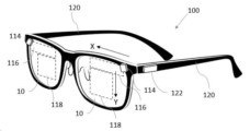
LOE(10)를 이용하는 일반적으로 100으로 지정된, 본 발명의 실시예의 교시들에 따른 근안 디스플레이 형태의 디바이스의 예시적인 구현이 도 1a 및 도 1b에 개략적으로 도시된다. 근안 디스플레이(100)는 이미지 광이 서로 평행한 외부 평면 세트에서의 내부 반사에 의해 1차원으로 포획되는 LOE(교대하여 "도파관(waveguide)", "기판(substrate)" 또는 "슬래브(slab)"라고 지칭됨)(10)로 이미지를 투입하기 위해 광학적으로 커플링되는 컴팩트 이미지 투영기(compact image projector, 또는 "POD")(114)를 채용한다.An exemplary implementation of a device in the form of a near eye display in accordance with the teachings of an embodiment of the present invention, generally designated 100, utilizing
광학 애퍼처 확장은 전형적으로 서로 평행하고 이미지 광의 전파 방향에 대해 경사지게 경사지는 한 세트의 부분 반사 표면(상호변경가능하게는 "패싯(facet)"으로 지칭됨)을 이용하는 이미지 조명을 점진적으로 재지향시키기 위한 하나 이상의 배열에 의해 LOE(10) 내에서 달성되며, 각 연속적인 패싯은 이미지 광의 일부를 편향된 방향으로 편향시킨다. 1차원 애퍼처 확장을 위해, 패싯들은 또한 사용자의 눈을 향해 이미지 광을 커플링 아웃한다. 일부 경우에, 본원에서 예시된 바와 같이, 2차원 애퍼처 확장은 또한 내부 반사에 의해 포획/가이드된, LOE 내의 이미지 조명을 점진적으로 재지향시키기 위해 영역(116) 내의 패싯들의 제1 세트를 채용함으로써 달성된다. 이어서 편향된 이미지 조명은 인접한 별개의 기판으로서 또는 단일 기판의 연속으로서 구현될 수 있는 제2 기판 영역(118)으로 통과하며, 여기서 커플링 아웃 배열체(예를 들어, 부분 반사 패싯들의 추가 세트)는 눈 움직임 박스(eye-motion box, EMB)로서 정의된 영역 내에 위치한 관찰자의 눈을 향해 이미지 조명의 일부분을 점진적으로 커플링 아웃함으로써, 제2 차원의 광학 애퍼처 확대를 달성한다. 당업계에 공지된 바와 같이, 영역들(116 및 118) 중 하나 또는 둘 모두 내에서 이미지 조명의 방향전환 및/또는 아웃커플링을 위한 회절 광학 요소(DOE)들을 사용하여 유사한 기능이 획득될 수 있다.Optical aperture expansion is typically used to progressively redirect image illumination using a set of partially reflective surfaces (interchangeably referred to as “facets”) that are parallel to each other and inclined at an angle to the direction of propagation of image light. This is achieved within the
전체 디바이스는 각 눈에 대해 별도로 구현될 수 있고, 바람직하게는 각 LOE(10)가 사용자의 대응하는 눈을 향하도록 사용자의 머리에 대해 지지된다. 여기에 도시된 바와 같은 특히 바람직한 한 가지 옵션으로, 지지 배열체는 디바이스를 사용자의 귀에 대해 지지하기 위한 측부들(120)을 갖는 안경테로서 구현된다. 머리띠, 바이저 또는 헬멧에 달리는 디바이스들을 포함하지만 이에 제한되지 않는 다른 형태들의 지지 배열체도 사용될 수 있다.The entire device may be implemented separately for each eye, and is preferably supported against the user's head with each
도면들 및 청구항들에서는 LOE의 제1 영역의 일반적인 연장 방향에서, 수평으로(도 1a) 또는 수직으로(도 1b) 연장되는 X축, 및 이에 수직으로, 즉, 도 1a에서는 수직으로 그리고 도 1b에서는 수평으로 연장되는 Y축을 기준으로 한다. 매우 대략적인 용어들로, 제1 LOE, 또는 LOE(10)의 제1 영역(116)은 X 방향으로 애퍼처 확대를 달성하는 것으로 고려될 수 있는 한편, 제2 LOE 또는 LOE(10)의 제2 영역(118)은 Y 방향으로 애퍼처 확대를 달성한다. 시야의 상이한 부분들이 전파하는 각도 방향들의 확산의 세부사항들은 아래에서 더 정확하게 다루어질 것이다. 도 1a에 도시된 바와 같은 배향은 LOE의 메인(제2 영역)에 진입하는 이미지 조명이 상부 에지로부터 진입하는 "하향식(top-down)" 구현으로서 여겨질 수 있는 반면, 도 1b에 도시된 배향은 여기서 Y축이라고 지칭되는 축이 수평으로 전개되는 "측방 투입(side-injection)" 구현으로 여겨질 수 있다는 점에 유념해야 한다. 나머지 도면들에서, 본 발명의 특정 실시예들의 다양한 특징들은 도 1a와 유사한 "하향식" 배향의 맥락에서 도시될 것이다. 그러나, 이들 특징들 모두는 본 발명의 범위 내에 또한 속하는 측방 투입 구현들에 균등하게 적용 가능한 것으로 이해해야 한다. 특정 경우들에서, 다른 중간 배향들이 또한 적용 가능하고, 명시적으로 배제되는 경우를 제외하고는 본 발명의 범위 내에 포함된다. 여기에 도시된 2차원 확장 실시예들은 단지 예시적이지만, 본 발명은 애퍼처 확장의 단일 치수만이 LOE에 의해 수행되는 실시예에도 적용가능하다.In the drawings and claims, the X axis extends horizontally (Fig. 1a) or vertically (Fig. 1b) in the general direction of extension of the first region of the LOE, and perpendicularly thereto, ie vertically in Fig. 1a and Fig. 1b In , it is based on the Y-axis extending horizontally. In very coarse terms, a first LOE, or
근안 디스플레이(100)는 소형 온보드 배터리(도시되지 않음)로부터의 전력 또는 몇몇 다른 적절한 전원을 통상적으로 채용하여, 이미지 투영기(114)를 작동시키기 위한 제어기(122)를 통상적으로 포함하여, 다양한 추가 구성요소들을 포함하는 것으로 이해될 것이다. 제어기(122)는 모두 당업계에 알려져 있는 바와 같이, 이미지 투영기를 구동하기 위한 적어도 하나의 프로세서 또는 프로세싱 회로부와 같은 모든 필요한 전자 구성요소들을 포함하는 것으로 이해될 것이다.Near
본 발명의 일 양태는 이미지 투영기가 시준된 이미지와 그 공액 이미지 둘 모두를 LOE(10)에 주입하도록 배열된 이미지 공액 생성기를 포함하는 이미지 투영기(114)의 구현예에 관한 것이다. 이미지 공액 생성기의 다양한 비제한적인 예들이 도 3 내지 도 8을 참조하여 이하에서 예시될 것이다.One aspect of the invention relates to an implementation of an image projector (114) that includes an image conjugate generator arranged so that the image projector injects both a collimated image and its conjugate image into the LOE (10). Various non-limiting examples of image conjugate generators will be illustrated below with reference to FIGS. 3-8 .
이에 따라, 도 3을 참조하면, 시청을 위해 이미지를 사용자를 향해 지향시키기 위한 도 1의 광학 시스템의 확대된 개략적인 부분도가 도시되어 있다. 광학 시스템은 투명 물질로 형성되고 제1 및 제2 상호 평행 주 외부 표면들(11a, 11b)에서의 내부 반사에 의한 이미지의 전파를 지원하기 위한 이들 표면들을 갖는 LOE(10)를 포함한다. LOE(10)는 또한 사용자의 눈을 향해 이미지를 커플링 아웃하기 위한 커플링 아웃 배열체(도 1의 영역(118)에서, 상술된 바와 같고 여기서는 도시되지 않음), 및 이 경우에 LOE(10)의 측방 에지로서 도시되는 커플링 인 애퍼처(15)를 갖는다.Accordingly, referring to FIG. 3 there is shown an enlarged schematic partial view of the optical system of FIG. 1 for directing an image towards a user for viewing. The optical system includes an
이미지-공액 쌍을 생성하기 위해 LOE(10)와 통합된 구조체들에 의존하는 대신에, 본 발명의 이러한 양태에 따른 이미지 투영기(114)는 시준된 이미지 또는 공액 이미지가 LOE(10)의 주 외부 표면들(11a, 11b) 중 어느 하나에 충돌하기 전에 이미지-공액 쌍을 생성하기 위한 이미지 공액 생성기를 포함한다.Instead of relying on structures integrated with
이에 따라, 도 3의 예에서, 이미지 투영기(114)는 이미지를 생성하기 위한 이미지 생성기(32), 이미지를 시준하기 위한 시준 광학계(31), 및 여기서 공액 이미지를 생성하는 제2 이미지 생성기(33)로서 구현되는 이미지 공액 생성기를 포함한다. 여기서 예시된 예에서, 이미지 생성기들(32 및 33)은 공통 시준 광학계(31)를 공유한다. 이미지 투영기(114)는 LOE(10)의 주 외부 표면들(11a 및 11b) 중 어느 하나에 시준 이미지 또는 그 공액 이미지가 충돌하기 전에, 시준 이미지 및 그 공액 이미지를 LOF(10) 내로 직접 도입하도록 커플링 인 애퍼처(15)에 커플링된다.Accordingly, in the example of FIG. 3 , the
이러한 솔루션은 도 2a 및 도 2b의 커플링 인 배열체들과 명백히 대조되며, 여기서 공액 이미지는 주 외부 표면들(또는 이러한 표면들의 연속이고 본원에서 이러한 목적을 위해 LOE의 주 외부 표면의 일부인 것으로 규정되는 커플링 프리즘의 표면들)로부터의 반사에 의해 LOE 자체 내에서 생성된다는 것이 이해될 것이다.This solution is in stark contrast to the coupling-in arrangements of FIGS. 2A and 2B , where the conjugated image is the major outer surfaces (or a continuation of such surfaces, defined herein for this purpose as being part of the major outer surface of the LOE). It will be appreciated that the LOE is created within the LOE itself by reflections from the surfaces of the coupling prism).
두 개의 이미지 생성기들(32, 33)은 하나의 반전된 동일한 이미지를 생성하도록 구동되고, 각 필드는 양 필드로부터 동일하게 도시된다. 디바이스의 조립 동안, 두 개의 이미지들이 LOE 내에서 상보적인 공액 이미지로서 정렬되도록 이미지 발생기 상의 두 개의 이미지들을 이동시키기 위해, 능동 정렬이 바람직하게는 기계적 조정에 의해 또는 더 바람직하게는 이미지 디스플레이 위치의 디지털 보정에 의해 사용된다. 이에 따라, LOE는 이러한 충진을 달성하기 위해 LOE의 어떠한 확장도 요구하지 않으면서, 1차 이미지 및 LOE 전체에 걸쳐 계속 커플링 인 애퍼처로부터의 그 공액 둘 모두로 "충진"된다.The two
본 발명의 이러한 그리고 모든 다른 구현들에서, 이미지 생성기(들)는 당업계에 공지된 임의의 유형의 마이크로-디스플레이 이미지 생성기일 수 있다. 적합한 예는 LCD 디스플레이와 같은 투과성 SLM 및 LCOS 디스플레이와 같은 반사성 SLM을 포함하는 공간 광 변조기(SLM), 및 oLED 디스플레이와 같은 능동 광 생성 디스플레이를 포함하지만, 이들로 제한되지는 않는다. 고속 스캐닝 레이저 빔이 그 스캐닝 모션과 동기적으로 변조되는 스캐닝 이미지 발생기가 또한 본 발명에 따른 이미지 발생기로서 사용될 수 있다.In these and all other implementations of the invention, the image generator(s) may be any type of micro-display image generator known in the art. Suitable examples include, but are not limited to, spatial light modulators (SLMs), including transmissive SLMs such as LCD displays and reflective SLMs such as LCOS displays, and active light generating displays such as oLED displays. A scanning image generator in which a high-speed scanning laser beam is modulated synchronously with its scanning motion can also be used as an image generator according to the present invention.
제2 이미지 생성기(33)에 대한 대안으로서, 본 발명의 다른 구현예들은 공액 이미지를 생성하기 위해 주 외부 표면들과 인접하지 않은 적어도 하나의 반사 표면으로서 이미지 공액인 생성기를 구현한다. 이러한 구현예들의 다양한 예들이 도 4a 내지 도 8을 참조하여 제시된다.As an alternative to the second image generator 33, other implementations of the present invention implement the image conjugate generator as at least one reflective surface not adjacent to the major exterior surfaces to create the conjugate image. Various examples of such implementations are presented with reference to FIGS. 4A-8 .
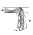
도 4a는 이미지 공액 생성기가 도파관(10) 외부에 있는 빔 증배기 또는 "혼합기" 구성(20)인 구현예를 예시한다. 그 자체로 특허 가능한 것으로 간주되는 혼합기(20)의 하나의 특히 바람직한 구현예가 도 4b에 더 상세히 도시된다.4A illustrates an implementation in which the image conjugate generator is a beam multiplier or “mixer”
개념적으로, 혼합기(20)는 도 2b의 혼합기(13)의 기능과 유사한 기능을 수행하지만, 이 경우, 그것은 도파관(10)의 일부가 아니라, LOE(10)와 이미지 생성기 및 시준 광학계를 포함하는 투영기 유닛(30) 사이에 위치된 이미지 투영기 어셈블리(114)의 어셈블리의 일부이다. 이 경우, 투영기 유닛(30)은 하나의 이미지를 생성하는 단일 이미지 생성기(32)를 갖는 반면, 혼합기(20)는 광선(40)을 부분적으로 반사하여 공액(광선(41))을 생성함으로써 이미지-공액 쌍을 생성한다. 그 후, 이미지 쌍은 도파관으로 주입된다. 혼합기(20)가 도파관 외부에 있기 때문에, 혼합기는 도파관에 제조 제약을 부과하지 않고 조립 중에 도파관과 능동적으로 정렬될 수 있다. 혼합기(20)는 광학 품질을 가질 필요가 없고 LOE 외부 표면과 동일 평면일 필요가 없는 외부 표면(21)뿐만 아니라 미러(22, 24) 및 빔 스플리터(23)의 다수의 층들을 포함할 수 있다. 이는 구조에 대한 제조 제약을 크게 단순화한다.Conceptually,
빔 증배기(20)의 구조와 관련하여, 본 발명의 빔 증배기는 적어도 하나의 중간 고반사 층의 존재에 의해 종래 공보들에 설명된 것들과 구별되며, 혼합기를 서로의 위에 적층된 두 개의 독립적인 혼합기들로 효과적으로 세분한다. 이에 따라, 광 빔 증배기(20)는 바람직하게는 복수의 평행한 계면 평면들을 규정하는 투명판들의 스택으로 형성되며, 복수의 평행한 계면 평면들에는:Regarding the structure of the
(a) N개의 반사기들의 세트 ― N은 적어도 3임 ―;(a) a set of N reflectors, where N is at least 3;
(b) 적어도 N-1개의 부분 반사 빔 스플리터들의 세트 ― 빔 스플리터들 각각은 반사기들의 세트의 두 개의 인접한 반사기들 사이에 개재됨 ― 를 규정하는 코팅들이 제공된다.(b) coatings are provided defining a set of at least N-1 partially reflecting beam splitters, each of which is sandwiched between two adjacent reflectors of the set of reflectors.
이 경우에 "반사기"는 바람직하게는 고반사성이며, 이는 적어도 LOE를 따른 전파에 관련된 각도 범위에서, 입사광의, 적어도 85%, 더 바람직하게는 적어도 90%, 그리고 통상적으로 적어도 95%를 반사한다는 것을 의미한다. 부분 반사 빔 스플리터들은 바람직하게는 대략 50%(50% ±10%) 반사기들이다. 빔 증배기가 사용자의 시야 밖에 있는 응용들에서, 반사기들 및 빔 스플리터들 둘 모두는 금속 코팅들을 사용하여 유리하게 구현될 수 있다. 투명도가 빔 증배기를 통해 장면을 보기 위해 요구되는 경우, 다층 유전체 코팅이 사용되어, 당업계에 공지된 바와 같이, 작은(근직교) 각도에서 비교적 높은 투명도를 제공하면서 높은 각도에서 요구되는 수준의 반사율을 제공한다.The "reflector" in this case is preferably highly reflective, meaning that it reflects at least 85%, more preferably at least 90%, and typically at least 95% of the incident light, at least in the angular range relevant to propagation along the LOE. means that Partial reflection beam splitters are preferably approximately 50% (50% ± 10%) reflectors. In applications where the beam multiplier is out of the user's field of view, both reflectors and beam splitters can advantageously be implemented using metallic coatings. When transparency is required to view a scene through a beam multiplier, a multilayer dielectric coating can be used, as is known in the art, to provide relatively high transparency at small (near orthogonal) angles while providing the required level of reflectivity at high angles. provides
중간 반사기는 혼합기를 두 개(또는 그 이상)의 서브 혼합기로 효과적으로 세분한다. 이는 이미지 및 그 공액으로 도파관의 충전을 달성하기 위해 혼합기에 필요한 길이의 2배만큼 감소한다. 일례에 따른 혼합기(20)의 입력 및 출력 애퍼처들은 도 4b에서 어두운 라인들로서 도시된다. 이들 애퍼처들은 혼합기의 전체 폭을 채울 필요가 없다. 사실상, 모든 반사기 및 빔 스플리터가 투명판들 사이의 내부 계면 평면에서 구현되는 것이 바람직할 수 있는 한편, 층상 구조물의 외부 표면은 광학적으로 비기능적인 표면이다. 여기서 "광학적으로 비기능적"은 이미지 광에 의해 도달되지 않는 표면, 또는 이들에 도달하는 임의의 이미지 광이 후속하여 LOE에 진입하지 않는 표면을 지칭한다. 이러한 경우에, 외부 표면은 폴리싱된 표면일 필요가 없고, 다른 요소와 평행할 필요가 없다. 이에 따라, 도 4a에 예시된 바와 같이, 혼합기(20)의 외부 두께는 LOE(10)의 두께(즉, 제1 및 제2 주 외부 표면들(11a 및 11b) 사이의 거리)와 상이할 수 있고, 통상적으로 더 클 수 있다. 최외측 반사기들(22) 사이의 거리는 LOE를 채우기 위해 LOE 두께와 일치하거나 그보다 약간 커야 한다.The intermediate reflector effectively subdivides the mixer into two (or more) submixers. This reduces by twice the length required for the mixer to achieve filling of the waveguide with the image and its conjugate. The input and output apertures of
이제 도 5 내지 도 8을 참조하면, 일부 구현예들에서, 외부 이미지 공액 생성기의 사용은 폴딩된 광 경로의 사용을 용이하게 하여, 어셈블리의 측면들로부터 벌크를 제거한다. 이에 따르면, 본 발명의 특정 실시예들에 따르면, LOE(20)는 기 시준된 이미지를 제1 주 외부 표면(11a)에 충돌하고 공액 이미지를 제2 주 외부 표면(11b)에 충돌하게 재지향시키기 위해 제1 및 제2 주 외부 표면들에 대해 경사지게 배치된 커플링 인 반사기(12)를 더 포함한다. 커플링 인 반사기(12)는 일정 범위의 각도로 구현될 수 있지만, 가장 바람직하게는 제1 및 제2 주 외부 표면에 대해 45도로 배치되어, 이미지 투영기의 광축을 90도로 효과적으로 절첩한다. 특정한 종래의 커플링 인 구성들과는 달리, 반사기(12)는 특히 LOE(20)의 두께 내에 위치되어, 일차 이미지 및 그 공액 이미지 둘 모두를 그들 각 상향/하향 전파 방향들을 향해 편향시킬 수 있다.Referring now to FIGS. 5-8 , in some implementations, the use of an external image conjugate generator facilitates the use of a folded light path, removing bulk from the sides of the assembly. Accordingly, according to certain embodiments of the present invention, the
도 5는 외부 혼합기(20)가 도파관에 수직으로 위치되는 하나의 이러한 구성을 도시한다. 이 경우, 45도 반사 커플링 인 표면(12)은 혼합기를 빠져나가는 이미지를 도파관으로 절첩한다. 웨지 프리즘(25)이 프리즘 표면에 수직인 각도로 혼합기 내로 중심 FOV 광을 커플링 인시키는 데 사용되는 것이 바람직하다. 접힘으로 인해, 혼합기의 애퍼처 폭은 도파관의 애퍼처 폭보다 커야 한다. 애퍼처의 정확한 사이즈는 디스플레이된 광의 각도 FOV 및 표면(12)의 절첩 각도에 의존한다. 이 예에서, 폭은 66% 증가한다.Figure 5 shows one such configuration in which the
또한, 이 경우, 혼합기(20)는 세 개의 서브 혼합기로 분할되어 있다. 그 결과, 혼합기의 길이는 (언급된 바와 같이 그리고 절첩 후에 폭(w)이 60%만큼 증가되므로) 증가될 필요가 없다. 이로 인해, 혼합기는 외부 미러 패싯들(22) 사이의 두 개의 내부 미러 패싯들(24)에 의해 세 개의 서브 혼합기들로 분할된다. 빔 스플리터(23)는 각 서브 혼합기의 중심 평면에 제공된다.Also, in this case, the
도 6은 도 5의 혼합기를 포함하는 전체 광학 시스템의 광 경로 도해를 도시한다. 이미지 발생기(32) 상의 세 개의 예시적인 지점들(픽셀들)은 렌즈(31)에 의해 시준되어 투영기 유닛(30)을 커플링 웨지 프리즘(25) 내로 그리고 혼합기(20) 내로 빠져나간다. 혼합기는 공액 필드를 생성하여, 전체 이미지 및 그 공액이 반사기(12)에 커플링 인함으로써 도파관(10)으로 커플링 인된다. 이 예에서, 광은 평행한 부분 반사 패싯들(11)의 세트에 의해 도파관으로부터 아이 모션 박스(EMB)(200)에 커플링 아웃된다. 패싯들(11)의 예는 단지 하나의 비제한적인 예이고, 커플링 아웃의 다른 메커니즘들, 예를 들어, 홀로그래픽 또는 이색성 격자들이 또한 가능하고 본원의 범위 내에 포함된다는 것이 주의되어야 한다. 마지막으로, 상이한 필드의 전파 각도가 매우 얕을 수 있지만, 혼합기(25)와 투영기 유닛(30) 사이의 입력 애퍼처는 비교적 작게 유지된다는 것을 알 수 있다.FIG. 6 shows an optical path diagram of the entire optical system including the mixer of FIG. 5 . Three exemplary points (pixels) on
도 7a 및 도 7b는 도파관 내에서 전파하는 이미지(도 7a) 및 그 공액(도 7b)의 두 개의 단면도들을 도시한다. 도 7a 및 도 7b를 오버레이하는 것은 도파관이 이미지 및 그 공액으로 완전히 채워지는 방법을 나타낸다. 이와 같이, 도파관 내에서 광 균질화가 달성된다. 이 예시는 LOE를 따라 도중의 임의의 위치에 따라 조명을 "이미지" 및 "공액"으로 세분하지만, 광은 LOE의 제1 및 제2 주 외부 표면으로부터 전파될 때 반사되기 때문에 이미지와 공액 사이에서 일정하게 교환된다는 점에 유의해야 한다. 본 발명의 하나의 특히 바람직한 양태의 특정한 한정 특징은 LOE의 커플링 인 애퍼처에 들어가고 커플링 인 반사기(12)에 도달하는 조명이 이미 이미지 및 공액 이미지 둘 모두로 반사기를 충전하는 것을 포함한다는 것이며, 이들 중 하나는 제1 주 외부 표면(11a) 상에 먼저 충돌하도록 도시된 바와 같이 상향으로 지향되고, 다른 하나는 제2 주 외부 표면에 우선 충돌하도록 도시되어 있는 바와 같이 하향으로 지향된다. 이미지가 "일차 이미지"이고 "공액 이미지"일 뿐만 아니라 표면이 "제1" 또는 "제2" 주 외부 표면이라고 불리는 것의 정의는 임의적이고, 일반적으로 이미지 생성기에 의해 생성된 "일차 이미지"가 단지 다양한 설계 고려사항에 따라 사용자가 볼 이미지인지 또는 그 이미지의 반전된 버전인지는 중요하지 않다.7a and 7b show two cross-sections of an image propagating in a waveguide ( FIG. 7a ) and its conjugate ( FIG. 7b ). Overlaying Figures 7a and 7b shows how the waveguide is completely filled with the image and its conjugate. In this way, light homogenization is achieved within the waveguide. This example subdivides illumination into "images" and "conjugates" along any location along the LOE, but since light is reflected as it propagates from the first and second major outer surfaces of the LOE, there is a separation between the image and the conjugate. It should be noted that they are constantly exchanged. A particular defining feature of one particularly preferred aspect of the present invention is that the illumination entering the coupling-in aperture of the LOE and reaching the coupling-in
도 7b에 도시된 바와 같이 커플링 인 반사기(12)로부터 반사된 하향 지향 광선들 중 일부가 빔 증배기(20)에 의해 중첩되는 영역에서 제2 주 외부 표면(11b) 상에 충돌한다는 것이 주목될 것이다. 중첩 영역에서 TIR을 유지하기 위해, 디바이스는 바람직하게는 요소들 사이에 작은 공극을 갖도록 조립되거나, 보다 바람직하게는 구성요소들 사이에 저굴절률 접착제를 사용하여 조립된다. 특히 얕은 각도의 광선 전파의 경우, LOE의 물질과 접착제 사이의 굴절률의 비교적 작은 차이는 TIR에 의해 전파하는 이미지 조명을 유지할 임계 각도를 규정하기에 충분하다. 대안적으로, 각도 선택적 다층 유전체 코팅이 LOE와의 중첩 영역에 적용되어 적합한 내부 반사 특성을 제공할 수 있다.Note that some of the downwardly directed rays reflected from the coupling-in
혼합기(20)를 채용하는 실시예들 모두에서, 혼합기는 LOE(10)로의 이미지들의 주입 전에 광학 시스템의 일부를 형성하고 LOE의 임의의 표면의 연장부를 포함하지 않기 때문에, 본원에서 기능적으로 투영기(114)의 일부인 것으로 임의로 규정된다. 제품의 실제 구성에서, 혼합기는 이미지 생성기 및 시준 광학계를 조합하는 투영기 유닛(30)과 반드시 통합될 필요는 없으며, 일부 경우에 투영기 유닛의 위치설정 전에 LOE에 대한 부착에 의해 더 편리하게 조립될 수 있다.In all of the embodiments employing the
도 8은 본 발명의 특정한 특히 바람직한 구현예들의 추가 특징을 도시한다. 이러한 특징에 따르면, 이미지 공액 생성기는 커플링 인 반사기(12)에 인접한 LOE(10)의 두께를 가로지르는 반사 표면(34)을 포함한다. LOE를 횡단하는 반사 표면(34)의 부분(121)은 반사기(12)에서의 반사 전에 투영기(114)로부터 LOE에 진입하는 광선들을 반사시키는 한편, 반사기(12)에 의해 이미 반사된 광선들을, 즉 LOE(20)를 따른 이미지 전파에 관련된 각도들로 투과시키도록 각도 선택적 반사 표면으로서 구현된다. 여기서도, 각도 선택적 반사 표면은 커플링 인 반사기에 인접한 LOE의 굴절률보다 낮은 굴절률을 갖는 광학 접착제를 사용하여 가장 편리하게 구현될 수 있으며, 그에 의해 반사기(12)에서의 반사 전과 후의 광선의 입사각들 사이에 놓이는 임계각을 제공한다. 각도 선택적 다층 유전체 코팅의 사용 또는 공극의 포함과 같은 전술한 다른 옵션이 또한 사용될 수 있다.Figure 8 shows further features of certain particularly preferred embodiments of the present invention. According to this feature, the image conjugate generator includes a
도 8에 도시된 비제한적인 예에서, 투영기(114)는 외부 혼합기를 통하기보다는 LOE의 주 외부 표면들에 수직인 단일의 연장된 반사 표면(34)의 사용에 의해 공액 이미지를 생성한다. 투영된 시준 이미지의 일부는 제1 주 외부 표면(11a)을 향해 상향으로 편향되는 일차 이미지에 대응하는 커플링 인 반사기(12) 상에 직접 입사한다. 이미지의 다른 부분은 표면(34)으로부터 반사되어, 커플링 인 반사기(12)에 의해 제2 주 외부 표면(11b)을 향해 하향으로 편향되는 공액 이미지를 생성한다. 반사 표면 영역(121)은 커플링 인 반사기(12)를 공액 이미지로 채우는데 기여하는 한편, 중첩 영역(122)은(위에서 설명된 바와 같이) 중첩 영역에서 하향 반사된 공액 이미지 광의 누설을 피하기 위해 각도 선택적 반사를 제공하도록 유사하게 처리된다.In the non-limiting example shown in FIG. 8 , the
도 8의 투영기(114)의 구조의 다른 양태는 편광 빔 스플리터 프리즘에 기초한 종래의 반사-SLM 이미지 투영기에서 채용된 원리에 기초한다. 구체적으로, 조명원(40)은 광이 LCOS, DLP 등과 같은 반사성 SLM(32)을 향해 반사되는 PBS 프리즘(35)에 조명을 도입한다. 반사된 이미지 조명은 1/4 파장판(도시되지 않음)과 연관된 반사 시준 렌즈(310)로 PBS를 통과하여, 반사된 시준 이미지가 PBS로부터 LOE 커플링 인 애퍼처를 향해 반사된다. 이미지 및 그 공액 모두를 제공하기 위한 이미지의 배가는 다른 이미지 조명이 먼저 표면(34)으로부터 반사되는 동안 이미지의 일부가 반사기(12) 상에 직접 입사함으로써 전술한 바와 같이 달성된다. 반사 렌즈(310) 아래에 있는 표면(34)의 영역에는 또한 유리하게는 PBS로부터의 반사 후에 관련 각도에서 TIR을 달성하기 위해 저굴절률 접착제와 같은 각도 선택적 반사 코팅이 제공될 수 있다. 필드 렌즈(313)와 같은 다른 렌즈가 광학 성능을 개선하기 위해 추가될 수 있다.Another aspect of the structure of the
이 구현에서, 프리즘 면(34)이 도파관(10)의 주 표면들에 직교하고, 반사 렌즈(310)를 떠나는 여기에 예시된 두 개의 평행 광선들이 도파관에 진입하기 전에 공액될 것이 특히 유리하다. 또한, 소스(40)로부터의 조명의 요구되는 입력 방향은 도파관의 주 표면에 대해 약 110도이고, 안경 프레임 폼 팩터에 매우 적합한 바와 같이, 디바이스의 양측에 통합될 구성요소들 사이에 약간의 발산을 갖는 매우 인체공학적인 설계에 적합하다는 것을 알 수 있다.In this implementation, it is particularly advantageous if the
각도 선택적 반사 특성들을 갖는 영역(121)에서 LOE의 두께를 가로지르는 반사 표면(34)의 사용은 전술한 본 발명의 다른 구현예들에도 적용가능하다. 예를 들어, 도 5 내지 도 7b의 빔 증배기(20)의 반사기들 중 하나가 LOE(20)의 두께를 가로지르는 표면으로서 구현되는 경우, 빔 증배기(20)의 요구되는 광학 입력 및 출력 애퍼처들이 상당히 감소될 수 있어서, 더 콤팩트한 설계를 초래한다.The use of a
상기한 설명은 단지 예들로서의 역할을 하는 것으로 의도된다는 것과, 많은 다른 실시예들이 본 발명의 범위 내에서 첨부된 청구항들에 정의된 바와 같이 가능하다는 것이 이해될 것이다.It will be understood that the foregoing description is intended to serve as examples only, and that many other embodiments are possible within the scope of the present invention as defined in the appended claims.
Claims (13)
(a) 투명한 물질로 형성되고, 상호 평행한 제1 주 외부 표면과 제2 주 외부 표면에서의 내부 반사에 의한 이미지의 전파를 지원하기 위한 상기 제1 주 외부 표면 및 상기 제2 주 외부 표면을 갖는 광 가이드 광학 요소(light-guide optical element, LOE) ― 상기 LOE는 상기 이미지를 상기 사용자의 눈을 향해 커플링 아웃(coupling out)하기 위한 커플링 아웃 배열체를 가지며, 상기 LOE는 커플링 인 애퍼처를 가짐 ―;
(b) 이미지를 생성하기 위한 이미지 생성기, 상기 이미지를 시준하기 위한 시준 광학계, 및 이미지 공액 생성기를 포함하는 이미지 투영기 ― 상기 이미지 투영기는 상기 시준 이미지와 그 공액 이미지가 상기 제1 주 외부 표면 또는 상기 제2 주 외부 표면 중 어느 하나에 충돌하기 전에, 상기 커플링 인 애퍼처 내로 상기 시준 이미지와 상기 공액 이미지를 도입하기 위해 상기 커플링 인 애퍼처에 커플링됨 ― 를 포함하는, 광학 시스템.An optical system for directing an image towards a user for viewing, comprising:
(a) a first major outer surface and a second major outer surface for supporting propagation of an image by internal reflection at the first and second major outer surfaces that are formed of a transparent material and are parallel to each other; a light-guide optical element (LOE) having a coupling-out arrangement for coupling out the image towards the eye of the user, the LOE coupling-in has an aperture;
(b) an image projector comprising an image generator for generating an image, collimating optics for collimating the image, and an image conjugate generator, the image projector having the collimated image and the conjugate image projected onto the first major outer surface or the image projector. coupled to the coupling-in aperture to introduce the collimated image and the conjugate image into the coupling-in aperture before impinging on either of the second major outer surfaces.
(a) N개의 반사기들의 세트 ― N은 적어도 3임 ―;
(b) 적어도 N-1개의 부분 반사 빔 스플리터들의 세트 ― 상기 빔 스플리터들 각각은 상기 반사기들의 세트의 두 개의 인접한 반사기들 사이에 개재됨 ― 를 규정하는 코팅들이 제공되는 것인, 광학 빔 증배기.An optical beam multiplier comprising a stack of transparent plates defining a plurality of parallel interfacial planes, wherein the plurality of parallel interfacial planes include:
(a) a set of N reflectors, where N is at least 3;
(b) provided with coatings defining a set of at least N−1 partially reflecting beam splitters, each of said beam splitters being sandwiched between two adjacent reflectors of said set of reflectors. .
Applications Claiming Priority (5)
| Application Number | Priority Date | Filing Date | Title |
|---|---|---|---|
| US202063086136P | 2020-10-01 | 2020-10-01 | |
| US63/086,136 | 2020-10-01 | ||
| US202063114110P | 2020-11-16 | 2020-11-16 | |
| US63/114,110 | 2020-11-16 | ||
| PCT/IL2021/051185 WO2022070197A1 (en) | 2020-10-01 | 2021-10-01 | Compound light-guide optical elements |
Publications (1)
| Publication Number | Publication Date |
|---|---|
| KR20230077721A true KR20230077721A (en) | 2023-06-01 |
Family
ID=80949868
Family Applications (1)
| Application Number | Title | Priority Date | Filing Date |
|---|---|---|---|
| KR1020237007989A KR20230077721A (en) | 2020-10-01 | 2021-10-01 | Composite Light Guide Optical Elements |
Country Status (7)
| Country | Link |
|---|---|
| US (1) | US20230359034A1 (en) |
| EP (1) | EP4222416A4 (en) |
| JP (1) | JP2023544093A (en) |
| KR (1) | KR20230077721A (en) |
| CN (1) | CN116368413A (en) |
| IL (1) | IL301401A (en) |
| WO (1) | WO2022070197A1 (en) |
Families Citing this family (1)
| Publication number | Priority date | Publication date | Assignee | Title |
|---|---|---|---|---|
| CN116635773A (en) | 2021-03-01 | 2023-08-22 | 鲁姆斯有限公司 | Optical system with compact coupling from projector into waveguide |
Family Cites Families (14)
| Publication number | Priority date | Publication date | Assignee | Title |
|---|---|---|---|---|
| EP2142953B1 (en) * | 2007-04-22 | 2019-06-05 | Lumus Ltd | A collimating optical device and system |
| IL232197B (en) * | 2014-04-23 | 2018-04-30 | Lumus Ltd | Compact head-mounted display system |
| CN109073821B (en) * | 2016-02-26 | 2021-11-02 | 奇跃公司 | Display system having multiple light pipes for multiple light emitters |
| CA2992213C (en) * | 2016-10-09 | 2023-08-29 | Yochay Danziger | Aperture multiplier using a rectangular waveguide |
| EP3397998A4 (en) * | 2017-02-22 | 2019-04-17 | Lumus Ltd. | Light guide optical assembly |
| KR20230025946A (en) * | 2017-03-22 | 2023-02-23 | 루머스 리미티드 | Overlapping facets |
| IL251645B (en) * | 2017-04-06 | 2018-08-30 | Lumus Ltd | Light-guide optical element and method of its manufacture |
| US10551544B2 (en) * | 2018-01-21 | 2020-02-04 | Lumus Ltd. | Light-guide optical element with multiple-axis internal aperture expansion |
| TWI813691B (en) * | 2018-05-23 | 2023-09-01 | 以色列商魯姆斯有限公司 | Optical system including light-guide optical element with partially-reflective internal surfaces |
| CA3109796C (en) * | 2018-08-26 | 2024-02-20 | Lumus Ltd. | Reflection suppression in near eye displays |
| US10983264B2 (en) * | 2019-01-24 | 2021-04-20 | Lumus Ltd. | Optical systems including light-guide optical elements with two-dimensional expansion |
| IL289182B1 (en) * | 2019-07-04 | 2024-02-01 | Lumus Ltd | Image waveguide with symmetric beam multiplication |
| WO2021137228A1 (en) * | 2019-12-30 | 2021-07-08 | Lumus Ltd. | Optical systems including light-guide optical elements with two-dimensional expansion |
| EP4022218A4 (en) * | 2020-02-02 | 2022-11-23 | Lumus Ltd. | Method for producing light-guide optical elements |
-
2021
- 2021-10-01 US US18/026,138 patent/US20230359034A1/en active Pending
- 2021-10-01 KR KR1020237007989A patent/KR20230077721A/en unknown
- 2021-10-01 CN CN202180067344.2A patent/CN116368413A/en active Pending
- 2021-10-01 JP JP2023516468A patent/JP2023544093A/en active Pending
- 2021-10-01 EP EP21874741.8A patent/EP4222416A4/en active Pending
- 2021-10-01 IL IL301401A patent/IL301401A/en unknown
- 2021-10-01 WO PCT/IL2021/051185 patent/WO2022070197A1/en unknown
Also Published As
| Publication number | Publication date |
|---|---|
| US20230359034A1 (en) | 2023-11-09 |
| EP4222416A1 (en) | 2023-08-09 |
| IL301401A (en) | 2023-05-01 |
| WO2022070197A1 (en) | 2022-04-07 |
| TW202221382A (en) | 2022-06-01 |
| EP4222416A4 (en) | 2024-03-27 |
| CN116368413A (en) | 2023-06-30 |
| JP2023544093A (en) | 2023-10-20 |
Similar Documents
| Publication | Publication Date | Title |
|---|---|---|
| US11714224B2 (en) | Optical systems including light-guide optical elements with two-dimensional expansion | |
| EP4022382B1 (en) | Optical system for two-dimensional expansion of an image reducing glints and ghosts from the waveduide | |
| KR20230077721A (en) | Composite Light Guide Optical Elements | |
| TWI839642B (en) | Optical beam multiplier and optical system for directing an image towards a user for viewing | |
| US20220390748A1 (en) | Optical Systems including Light-Guide Optical Elements with Two-Dimensional Expansion | |
| KR20230144000A (en) | Optical system comprising light guide optical elements for two-dimensional expansion with retarder elements | |
| TW202346963A (en) | Optical system for directing an image for viewing | |
| CN118103755A (en) | Optical system for near-eye display | |
| CN117897646A (en) | Independent conjugate image generation |