KR20220080489A - Lapping tool for glass gorming mold - Google Patents
Lapping tool for glass gorming mold Download PDFInfo
- Publication number
- KR20220080489A KR20220080489A KR1020200169652A KR20200169652A KR20220080489A KR 20220080489 A KR20220080489 A KR 20220080489A KR 1020200169652 A KR1020200169652 A KR 1020200169652A KR 20200169652 A KR20200169652 A KR 20200169652A KR 20220080489 A KR20220080489 A KR 20220080489A
- Authority
- KR
- South Korea
- Prior art keywords
- lapping
- thermoforming mold
- mold
- shape
- glass
- Prior art date
Links
Images


Classifications
-
- B—PERFORMING OPERATIONS; TRANSPORTING
- B24—GRINDING; POLISHING
- B24B—MACHINES, DEVICES, OR PROCESSES FOR GRINDING OR POLISHING; DRESSING OR CONDITIONING OF ABRADING SURFACES; FEEDING OF GRINDING, POLISHING, OR LAPPING AGENTS
- B24B37/00—Lapping machines or devices; Accessories
- B24B37/11—Lapping tools
-
- B—PERFORMING OPERATIONS; TRANSPORTING
- B24—GRINDING; POLISHING
- B24B—MACHINES, DEVICES, OR PROCESSES FOR GRINDING OR POLISHING; DRESSING OR CONDITIONING OF ABRADING SURFACES; FEEDING OF GRINDING, POLISHING, OR LAPPING AGENTS
- B24B19/00—Single-purpose machines or devices for particular grinding operations not covered by any other main group
- B24B19/20—Single-purpose machines or devices for particular grinding operations not covered by any other main group for grinding dies
-
- B—PERFORMING OPERATIONS; TRANSPORTING
- B24—GRINDING; POLISHING
- B24B—MACHINES, DEVICES, OR PROCESSES FOR GRINDING OR POLISHING; DRESSING OR CONDITIONING OF ABRADING SURFACES; FEEDING OF GRINDING, POLISHING, OR LAPPING AGENTS
- B24B37/00—Lapping machines or devices; Accessories
- B24B37/11—Lapping tools
- B24B37/20—Lapping pads for working plane surfaces
- B24B37/24—Lapping pads for working plane surfaces characterised by the composition or properties of the pad materials
- B24B37/245—Pads with fixed abrasives
-
- B—PERFORMING OPERATIONS; TRANSPORTING
- B24—GRINDING; POLISHING
- B24B—MACHINES, DEVICES, OR PROCESSES FOR GRINDING OR POLISHING; DRESSING OR CONDITIONING OF ABRADING SURFACES; FEEDING OF GRINDING, POLISHING, OR LAPPING AGENTS
- B24B37/00—Lapping machines or devices; Accessories
- B24B37/11—Lapping tools
- B24B37/20—Lapping pads for working plane surfaces
- B24B37/26—Lapping pads for working plane surfaces characterised by the shape of the lapping pad surface, e.g. grooved
-
- C—CHEMISTRY; METALLURGY
- C03—GLASS; MINERAL OR SLAG WOOL
- C03B—MANUFACTURE, SHAPING, OR SUPPLEMENTARY PROCESSES
- C03B11/00—Pressing molten glass or performed glass reheated to equivalent low viscosity without blowing
- C03B11/06—Construction of plunger or mould
Landscapes
- Engineering & Computer Science (AREA)
- Mechanical Engineering (AREA)
- Chemical & Material Sciences (AREA)
- Manufacturing & Machinery (AREA)
- Materials Engineering (AREA)
- Organic Chemistry (AREA)
- Polishing Bodies And Polishing Tools (AREA)
Abstract
본 발명은 열성형금형의 외표면을 형상과 모양에 관계 없이 긴밀하게 밀착되면석 균일한 압력으로 마찰하여 목적하는 조도를 얻을 수 있는 것은 물론 기계적으로 랩핑을 수행하기 때문에 작업시간을 대폭 줄일 수 있는 것은 물론, 우수하고 균일한 상태를 지속적을 유지하여 열성형금형의 품질을 높이는 것은 물론 이를 통하여 성형되는 3D 글라스의 품질 또한 우수하게 할 수 있도록 한 것으로서;
랩핑기에 구비되는 회전축에 장착할 수 있도록 상부 중앙에 장착팁을 돌출시킨 툴바디와;
상기 툴바디의 저면에 돌출시키는 랩퍼부착면과;
상기 랩퍼부착면에 부착되어 랩핑기의 베드에 안착되는 열성형금형의 표면을 랩핑하기 위한 랩퍼를 포함하는 것이 특징이다.According to the present invention, when the outer surface of the thermoforming mold is closely adhered regardless of shape and shape, the desired roughness can be obtained by friction with uniform pressure, and the working time can be significantly reduced because lapping is performed mechanically. Of course, it is possible to improve the quality of the thermoforming mold by continuously maintaining an excellent and uniform state, as well as to improve the quality of the 3D glass to be molded through this;
a tool body with a mounting tip protruding from the center of the upper portion so as to be mounted on a rotating shaft provided in the lapping machine;
a wrapper attachment surface protruding from the bottom surface of the tool body;
It is characterized in that it includes a wrapper for wrapping the surface of the thermoforming mold which is attached to the wrapper attachment surface and is seated on the bed of the wrapping machine.
Description
본 발명은 글라스열성형금형용 랩핑툴에 관한 것으로서 더욱 상세하게는 휴대단말기 등과 같은 전자제품에 장착되는 3D 글라스를 성형하기 위한 금형의 표면을 굴곡과 같은 3D 형상에 관계 없이 높은 조도로 고르게 연마할 수 있도록 한 랩핑툴의 제공에 관한 것이다.The present invention relates to a lapping tool for a glass thermoforming mold, and more particularly, the surface of a mold for molding 3D glass mounted on electronic products such as portable terminals can be polished evenly with high roughness regardless of 3D shape such as curvature It is related to the provision of a wrapping tool designed to make
휴대단말기와 같은 전자제품의 디스플레이를 구성하기 위한 글라스의 경우 종래 평면 타입에서 필요에 따라 라운드 또는 굴곡을 가지는 3D 타입으로 변경되면서 이러한 글라스를 열성형하기 위한 금형의 형상 또한 3D 타입으로 변경되면서 완성도를 높이기 위하여 열성형금형의 표면 조도에 많은 신경을 쓰게 되는 것이 사실이다.In the case of glass for constituting the display of electronic products such as mobile terminals, the shape of the mold for thermoforming the glass is also changed to the 3D type while changing from the conventional flat type to the 3D type having a round or curved shape as needed. It is true that much attention is paid to the surface roughness of the thermoforming mold in order to increase it.
상기와 같이 열성형금형의 표면을 연마하기 위하여 다양한 랩핑툴을 이용하고 있으며, 종래의 대표적인 랩핑툴의 기술적인 구성을 특허문헌을 통하여 살펴보면 다음과 같다.Various lapping tools are used to polish the surface of the thermoforming mold as described above, and the technical configuration of a conventional typical lapping tool is as follows through the patent literature.
특허문헌 1은, 금형 성형부 표면을 사상 작업하는 것에 있어서,Patent Document 1, in the finishing operation of the surface of the mold forming part,
내부에 공간부(11)와 하단에 작동공(12)을 형성하는 공구생크(10)와,A tool shank (10) forming a space (11) therein and an operation hole (12) at the lower end thereof;
상기 공구생크(10)내부에 삽입되고 하단에 단차진 형태로 작동공(12)을 통해 하부로 돌출된 연결부(25)를 형성하는 작동몸체(20)와,an operating body 20 inserted into the tool shank 10 and forming a connecting portion 25 protruding downward through the operating hole 12 in a stepped shape at the bottom thereof;
상기 작동몸체(20)의 하부 연결부(25)에 결합되는 반구형의 연삭휠(30)과,a hemispherical grinding wheel 30 coupled to the lower connection part 25 of the working body 20;
상기 작동몸체(20)의 내부에 삽입되어 연삭휠(30)이 탄발 작동하면서 금형 성형부 표면에 대해 일정 압력을 유지하도록 하는 탄발스프링(40) 및 상기 공구생크(20)의 상단을 마감하도록 결합되는 마감캡(45)으로 구성되어 이루어진 것을 특징으로 하고 있다.A resilient spring 40 inserted into the working body 20 to maintain a constant pressure on the surface of the mold forming part while the grinding wheel 30 is elastically operated and coupled to close the upper end of the tool shank 20 It is characterized in that it is composed of a closing cap (45).
특허문헌 2는, 연마장치의 연마툴(101)과 결합할 수 있도록 결합수단(102)을 가지는 베이스(105)와;Patent Document 2 discloses a
상기 베이스(105)의 저면에 브러쉬(110)를 장착할 수 있도록 형성하는 브러쉬홈(111)과;a brush groove 111 formed on the bottom surface of the
상기 브러쉬홈(111)에 많은 수의 모(毛, 112)를 집합시켜 접착수단(113)으로 고정하는 브러쉬(110)와;a
상기 브러쉬(110)의 중앙에는 연마제가 투입될 수 있도록 연마제홀(114)을 형성한 도넛형태로 구성하고;It is configured in the shape of a donut in which an abrasive hole 114 is formed in the center of the
상기 모(112)에는 에칭(Etching) 처리하여 모(112)의 끝단에 형성하는 첨예부(115)와, 상기 첨예부(115)에서 모(112)의 몸체(116) 방향 외면에는 연마제(118)가 연마과정에서 모(112)로부터 이탈되지 않고 붙어있을 수 있도록 표면에 형성하는 연마제부착홈(117)을 포함하는 것을 특징으로 하고 있다.The hair 112 has a sharpened
상기와 같은 선행기술 중 특허문헌 1의 경우에는 반구형상의 연삭휠을 구비하여 직선 또는 평면은 물론 굴곡이 있는 표면의 연마도 가능하도록 하고 있으나, 연마과정에서 발생하는 미세한 충격과 진동이 금형으로 지속적을 전달되어 흑연재질의 금형에 균영을 발생시키는 것은 물론 심할 경우에는 파손에 이르게 하는 원인디 된다.Among the prior art as described above, Patent Document 1 has a hemispherical grinding wheel to enable grinding of straight or flat as well as curved surfaces, but the fine impact and vibration generated during the grinding process is continuously applied to the mold. It is transmitted to the mold of graphite material and causes micro-growth in the mold, and in severe cases, it is the cause of damage.
특히 반구형상의 특성에 의하여 수 mm에 지나지 않은 곡률과 변형으로 이루어진 3D 형상의 표면 전체를 고르고 균일하게 랩핑하는 것이 현실적으로 어려운 것은 물론, 열성형금형의 굴곡진 부분으로 연삭휠이 진입하거나 마찰되지 못하여 랩핑이 불가능한 실정이다.In particular, due to the characteristic of the hemispherical shape, it is not only realistically difficult to evenly and uniformly wrap the entire surface of a 3D shape consisting of a curvature and deformation of only a few millimeters, but also because the grinding wheel does not enter or rub into the curved part of the thermoforming mold, so the lapping This is an impossible situation.
특허문헌 2의 경우에는 브러쉬 휠을 모(毛) 재질을 사용함으로서 평탄한 연마대상체는 물론, 곡률이나 굴곡을 가지는 연마대상체의 표면과 절곡된 내,외부의 연마를 용이하게 할 수 있고, 평평한 하나의 면이 아닌 여러 면을 가지는 연마대상체의 표면 또한 용이하게 연마할 수 있도록 하는 것이다.In the case of Patent Document 2, by using the brush wheel as a hair material, it is possible to facilitate the polishing of a flat object, as well as the surface of the object having curvature or curvature, and the bent inner and outer surfaces, and a flat one The surface of the object to be polished having several surfaces other than the surface can also be easily polished.
특허문헌 2의 경우에는 모재질로 구성되어 열성형금형의 형상에 구애받지 않고 랩핑하는 것은 가능할 것이나, 특히 모의 내구성이 높은 경우에는 오히려 금형의 표면을 긁게 되는 손상을 입힐 우려가 높고, 이러한 현상을 방지하기 위하여 모의 내구성을 낮출 경우에는 목적하는 조도를 얻는 것이 힘들게 되는 문제점에 봉착하게 된다.In the case of Patent Document 2, it is composed of a base material and it is possible to wrap regardless of the shape of the thermoforming mold, but in particular, if the durability of the simulation is high, there is a high risk of damaging the surface of the mold rather than scratching, and this phenomenon In the case of lowering the simulation durability in order to prevent it, it is difficult to obtain the desired illuminance.
이러한 문제를 해결하기 위하여 금형의 표면을 기계를 이용하여 1차 랩핑을 수행한 후 마지막으로는 작업자가 부드러운 종이사포를 이용하여 수사상(수작업을 통한 연마)으로 표면을 마무리하고 있는 실정이다.In order to solve this problem, after performing the first lapping of the surface of the mold using a machine, the operator is finally finishing the surface with soft paper sandpaper (polishing by hand).
상기와 같은 수사상 작업을 수행할 경우에는 금형 표면의 랩핑을 원하는 조도로 유지할 수 있으나 작업을 완료하기 위하여 여러 번의 작업을 반복하여야 하기 때문에 많은 인력이 투입되어 시간과 노력을 들여 세밀하게 작업을 수행하여야 한다.When performing the above-mentioned investigative work, the lapping of the mold surface can be maintained at the desired roughness, but since the work must be repeated several times to complete the work, a lot of manpower is put in, and time and effort are spent to perform the work in detail shall.
인력에 의존할 경우에는 랩핑과정에서 미세분진이 발생하게 되고 이러한 미세분진을 안전장구를 착용한 상태라 하더라도 의도치 않게 작업자의 호흡기를 통하여 유입될 경우에는 건강을 해치게 되는 좋지 않은 원인으로 작용하게 되고, 쾌적한 작업환경을 유지하는 것이 어렵게 되는 문제를 야기한다.In the case of dependence on manpower, fine dust is generated during the lapping process, and if such fine dust is unintentionally introduced through the respiratory tract of the worker even when wearing safety gear, it acts as a bad cause that harms health. , it causes a problem that it is difficult to maintain a comfortable working environment.
특히 작업자의 숙련도에 따라 랩핑 시간은 물론 완성된 금형의 표면 조도가 다르기 때문에 우수하고 균일한 상태의 표면조도를 지속적을 유지하는 것이 현실적을 힘들고, 이러한 금형을 통하여 성형된 3D 글라스의 품질에까지 영향을 미치게 되는 등 여러 문제점들이 발생하고 있는 실정이다.In particular, since lapping time and the surface roughness of the finished mold are different depending on the skill of the operator, it is difficult to maintain an excellent and uniform surface roughness, and this affects the quality of 3D glass molded through such a mold. There are several problems, such as being crazy.
이에 본 발명에서는 상기와 같은 문제점들을 해결하기 위하여 발명한 것으로서, 랩핑기(101)에 구비되는 장착축(102)에 장착할 수 있도록 상부 중앙에 장착팁(105)을 돌출시킨 툴바디(106)와;Therefore, in the present invention, as invented to solve the above problems, the
상기 툴바디(106)의 저면에 돌출시키는 랩퍼부착면(116)과;a
상기 랩퍼부착면(116)에 부착되어 랩핑기(101)의 베드(109)에 안착되는 열성형금형(110)의 표면을 랩핑하기 위한 랩퍼(115)를 포함하여;a
열성형금형의 외표면을 형상과 모양에 관계 없이 긴밀하게 밀착되면석 균일한 압력으로 마찰하여 목적하는 조도를 얻을 수 있고 기계적으로 랩핑을 수행하기 때문에 작업시간을 대폭 줄일 수 있는 것은 물론, 우수하고 균일한 상태를 지속적으로 유지하여 열성형금형의 품질을 높이는 것은 물론 이를 통하여 성형되는 3D 글라스의 품질 또한 우수하게 할 수 있는 목적 달성이 가능하다.If the outer surface of the thermoforming mold is closely adhered regardless of shape and shape, the desired roughness can be obtained by friction with uniform pressure. It is possible to achieve the purpose of improving the quality of the thermoforming mold by continuously maintaining a uniform state, as well as improving the quality of the 3D glass to be molded through this.
본 발명은 랩핑기에 장착되는 랩핑툴을 개선하여 기계적인 랩핑을 통하여 랩핑에 소요되는 시간을 대폭 줄이면서 랩핑과정에서의 압력과 속도를 일정하게 유지하여 금형 표면의 조도를 균일하면서도 우수하게 유지할 수 있도록 하면서 랩핑시간을 대폭 단축할 수 있는 효과를 가진다.The present invention improves the lapping tool mounted on the lapping machine so that the time required for lapping is greatly reduced through mechanical lapping, and the pressure and speed in the lapping process are kept constant so that the roughness of the mold surface can be maintained uniformly and excellently. It has the effect of significantly shortening the lapping time.
본 발명은 열성형금형의 표면 랩핑을 기계적으로 수행함으로서 안전하고 쾌적한 작업환경을 유지할 수 있는 것은 물론, 랩핑과정에서 발생하는 미세분진에 의하여 발생할 수 있는 작업자의 건강우려를 배제할 수 있는 효과를 가진다.The present invention has the effect of being able to maintain a safe and comfortable working environment by mechanically performing the surface lapping of the thermoforming mold, as well as eliminating the health concerns of the workers that may be caused by the fine dust generated during the lapping process. .
본 발명은 랩핑툴의 구조를 개선하여 평평한 면은 물론 굴곡을 가지는 3D면까지 균일하면서도 우수한 표면조도를 유지할 수 있도록 함으로서 금형의 제조 용이성은 물론, 이 금형을 이용한 글라스의 성형 용이성 및 우수하고 균일한 품질의 제품을 얻을 수 있는 등 다양한 효과를 가진다.The present invention improves the structure of a lapping tool so that it can maintain uniform and excellent surface roughness not only on the flat surface but also on the curved 3D surface, so that not only the manufacturing ease of the mold, but also the molding of the glass using the mold and the excellent and uniform surface roughness can be achieved. It has various effects such as obtaining quality products.
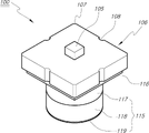
도 1은 본 발명의 기술이 적용된 글라스열성형금형용 랩핑툴을 도시한 분해사시도.
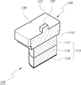
도 2는 본 발명의 기술이 적용된 글라스열성형금형용 랩핑툴의 정면상태 사시도.
도 3은 본 발명의 기술이 적용된 글라스열성형금형용 랩핑툴의 배면상태 사시도.
도 4는 본 발명의 기술이 적용된 글라스열성형금형용 랩핑툴을 도시한 파절 사시도.
도 5는 본 발명의 기술이 적용된 글라스열성형금형용 랩핑툴의 단면 상태의 구성도.
도 6은 본 발명의 기술이 적용된 글라스열성형금형용 랩핑툴의 사용 상태를 도시한 구성도.1 is an exploded perspective view showing a lapping tool for a glass thermoforming mold to which the technology of the present invention is applied.
2 is a perspective view of a front state of a lapping tool for a glass thermoforming mold to which the technology of the present invention is applied.
3 is a rear perspective view of a lapping tool for a glass thermoforming mold to which the technology of the present invention is applied.
Figure 4 is a fractured perspective view showing a lapping tool for a glass thermoforming mold to which the technology of the present invention is applied.
5 is a configuration diagram of a cross-sectional state of a lapping tool for a glass thermoforming mold to which the technology of the present invention is applied.
6 is a configuration diagram showing a state of use of a lapping tool for a glass thermoforming mold to which the technology of the present invention is applied.
이하 첨부되는 도면과 관련하여 상기 목적을 달성하기 위한 본 발명의 바람직한 구성과 작용에 대하여 설명하면 다음과 같다.Hereinafter, the preferred configuration and operation of the present invention for achieving the above object will be described with reference to the accompanying drawings.
도 1은 본 발명의 기술이 적용된 글라스열성형금형용 랩핑툴을 도시한 분해사시도, 도 2는 본 발명의 기술이 적용된 글라스열성형금형용 랩핑툴의 정면상태 사시도, 도 3은 본 발명의 기술이 적용된 글라스열성형금형용 랩핑툴의 배면상태 사시도, 도 4는 본 발명의 기술이 적용된 글라스열성형금형용 랩핑툴을 도시한 파절 사시도, 도 5는 본 발명의 기술이 적용된 글라스열성형금형용 랩핑툴의 단면 상태의 구성도, 도 6은 본 발명의 기술이 적용된 글라스열성형금형용 랩핑툴의 사용 상태를 도시한 구성도로서 함께 설명한다.1 is an exploded perspective view showing a lapping tool for a glass thermoforming mold to which the technology of the present invention is applied, FIG. 2 is a front perspective perspective view of the lapping tool for a glass thermoforming mold to which the technique of the present invention is applied, and FIG. A perspective view of the rear side of the lapping tool for a thermoforming mold for glass, FIG. 4 is a broken perspective view showing the lapping tool for a thermoforming mold for glass to which the technology of the present invention is applied, and FIG. 5 is a cross-sectional state of the lapping tool for a thermoforming mold for glass to which the technique of the present invention is applied 6 is a configuration diagram showing the state of use of the lapping tool for glass thermoforming mold to which the technology of the present invention is applied.
본 발명의 기술이 적용되는 글라스열성형금형용 랩핑툴(100)은, 랩핑기(101)에 구비되는 장착축(102)에 장착할 수 있도록 상부 중앙에 장착팁(105)을 돌출시킨 개략 사각형상의 툴바디(106)를 구비한다.The
상기 툴바디(106)의 측면 모서리 또는 측면에는 탈부착 시 취급의 용이성을제공할 수 있도록 모따기(107) 또는 요입홈(108)을 형성하도록 하고, 상기 툴바디(106)의 저면에는 랩핑기(101)의 베드(109) 상에 안착되는 열성형금형(110)의 표면을 실질적으로 랩핑하기 위한 랩퍼(115)를 부착하기 위한 랩퍼부착면(116)을 돌출시킨다.A
상기 툴바디(106)는 장착의 용이성을 제공하면서 빈번한 교체작업에도 견고한 장착성을 유지할 수 있도록 금속재질로 구성하는 것이 바람직할 것이며, 사각형 외에 다양한 형상으로도 구성할 수 있을 것이다.It is preferable that the
상기 랩퍼부착면(116)에 부착되는 랩퍼(115)는, 최 상단에 위치하여 랩퍼부착면(116)과 접착제 또는 양면테이프와 같은 접착수단으로 견고하게 부착되어 제 형상을 유지하기 위한 형상유지부(117)를 구비한다.The
상기 형상유지부(117)의 하측에는 랩핑과정에서 열성형금형(110)과 연접되어 랩핑하는 과정에서 열성형금형(110)의 형상과 모양을 따라 자유롭게 변형될 수 있도록 변형부(118)를 형성하고, 상기 변형부(118)의 하단에는 실제 열성형금형(110)와 밀착되어 랩핑을 수행하는 랩핑부(119)를 형성하여 구성한다.A
상기 형상유지부(117)는 랩핑 과정에서 랩퍼(115) 전체가 급격하게 변형되는 것을 방지할 수 있도록 고밀도에서 중밀도 정도의 우레탄 폼으로 구성하여 랩핑 과정에서 적당한 압력을 가하더라도 변형의 우려가 없도록 한다.The
상기 변형부(118)는 랩핑과정에서 열성형금형(110)의 표면 형상에 맞게 가변될 수 있도록 저밀도 스펀지로 구성하여 열성형금형(110)의 전체 표면을 고르게 랩핑하는 데 지장이 없도록 하는 것이 좋다It is preferable that the
상기 랩핑부(119)는 0.5mm 이하의 두께를 가지는 박판의 종이사포를 부착하여 구성하며, 열성형금형(110)이 요구하는 조도에 따라 종이사포의 거칠기는 달라질 수 있을 것이므로 어느 하나로 특정하지는 않는다.The
본 발명에서는 랩퍼(115)의 직경은 25mm이고 형상유지부(117)와 변형부(118)의 높이를 각각 9mm로 하고 있으나 랩핑 대상인 열성형금형(110)의 종류, 크기, 조도 등에 따라 가변될 수 있을 것이어서 치수를 한정하지는 않는다.In the present invention, the diameter of the
상기와 같은 본 발명의 기술이 적용된 글라스열성형금형용 랩핑툴의 사용상태를 살펴보면 다음과 같다.The state of use of the lapping tool for glass thermoforming mold to which the technology of the present invention is applied as described above is as follows.
랩핑기(101)의 베드(109)에는 랩핑하고자 하는 열성형금형(110)을 안착시키고 장착축(102)에 랩퍼(115)를 부착한 툴바디(106)를 결합시킨 후 베드(109)와 장착축(102)을 작동시켜 X, Y방향으로 지속적으로 움직여 랩퍼(115)의 최 하단에 부착된 랩핑부(119)가 열성형금형(110)의 표면과 마찰하여 열성형금형(110) 표면의 조도를 목적하는 바와 같이 달성할 수 있도록 한다.The
이와 같이 랩핑을 수행하는 과정에서는 입체적으로 움직이는 과정에서 발생하는 큰 충격과 진동에 대하여 랩퍼(115)가 변형되지 않도록 형상유지부(117)가 안정되게 잡아주면서 제 형상을 안정적으로 유지하게 되며, 상기 형상유지부(117)의 아래측에 부착된 변형부(118)가 열성형금형(110)의 표면 형상에 맞게 변형 되면서 열성형금형과 균일한 압력으로 밀착상태를 이루게 된다.In the process of performing the lapping as described above, the
상기 변형부(118)가 열성형금형(110)의 표면 형상에 맞게 변형 되는 것은 저밀도의 스펀지 재질로 구성하여 열성형금형(110)과 연접되고 가압 시 열성형금형(110)의 형상에 맞게 형상이 변형될 수 있는 것이다.The
그러면 변형부(118)의 하단에 부착된 박형의 랩핑부(119)가 열성형금형(110)과 마찰하여 표면을 목적하는 조도로 유지할 수 있게 되는 것이며, 랩핑 과정에서 랩핑부(119)의 마모 또는 손상이 있을 경우에는 새로운 것으로 교환하여 작업을 수행하면 되는 것이다.Then, the
상기와 같이 열성형금형(110)의 외표면을 형상과 모양에 관계 없이 긴밀하게 밀착되면석 균일한 압력으로 마찰하여 목적하는 조도를 얻을 수 있는 것은 물론 기계적으로 랩핑을 수행하기 때문에 작업시간을 대폭 줄일 수 있는 것은 물론, 우수하고 균일한 상태를 지속적을 유지하여 열성형금형의 품질을 높이는 것은 물론 이를 통하여 성형되는 3D 글라스의 품질 또한 우수하게 할 수 있는 장점을 가지게 된다.As described above, when the outer surface of the
100; 글라스열성형금형용 랩핑툴
105; 툴바디
110; 열성형금형
115; 랩퍼
117; 형상유지부
118; 변형부
119; 랩핑부100; Lapping tool for glass thermoforming mold
105; toolbar
110; thermoforming mold
115; rapper
117; shape maintaining part
118; deformation part
119; lapping department
Claims (3)
상기 툴바디(106)의 저면에 돌출시키는 랩퍼부착면(116)과;
상기 랩퍼부착면(116)에 부착되어 랩핑기(101)의 베드(109)에 안착되는 열성형금형(110)의 표면을 랩핑하기 위한 랩퍼(115)를 포함하는 것을 특징으로 하는 글라스열성형금형용 랩핑툴.a tool body 106 in which a mounting tip 105 is protruded from the upper center so as to be mounted on a mounting shaft 102 provided in the lapping machine 101;
a wrapper attachment surface 116 protruding from the bottom surface of the tool body 106;
Lapping for glass thermoforming mold, characterized in that it includes a wrapper 115 for wrapping the surface of the thermoforming mold 110 attached to the wrapper attachment surface 116 and seated on the bed 109 of the wrapping machine 101 tool.
상기 랩퍼(115)는, 최 상단에 위치하여 랩퍼부착면(116)과 접착수단으로 부착되어 제 형상을 유지하는 형상유지부(117)와;
상기 형상유지부(117)의 하측에 위치하여 랩핑과정에서 열성형금형(110)과 연접되어 랩핑하는 과정에서 열성형금형(110)의 형상과 모양을 따라 자유롭게 변형될 수 있게 하는 변형부(118)와;
상기 변형부(118)의 하단에 부착되어 열성형금형(110)와 밀착되어 랩핑을 수행하는 랩핑부(119)를 포함하는 것을 특징으로 하는 글라스열성형금형용 랩핑툴.as in claim 1;
The wrapper 115 includes: a shape maintaining part 117 positioned at the top and attached to the wrapper attachment surface 116 and an adhesive means to maintain its shape;
A deformable part 118 that is located below the shape maintaining part 117 and is connected to the thermoforming mold 110 during the lapping process and allows it to be freely deformed according to the shape and shape of the thermoforming mold 110 during the lapping process. )Wow;
A lapping tool for glass thermoforming mold, characterized in that it includes a lapping part (119) attached to the lower end of the deformable part (118) to be in close contact with the thermoforming mold (110) to perform lapping.
상기 형상유지부(117)는 우레탄 폼으로 구성하고;
상기 변형부(118)는 스펀지로 구성하며;
상기 랩핑부(119)는 박판의 종이사포인 것을 특징으로 하는 글라스열성형금형용 랩핑툴.3. The method of claim 2;
The shape maintaining part 117 is composed of urethane foam;
the deformable part 118 is made of a sponge;
The lapping part 119 is a lapping tool for a glass thermoforming mold, characterized in that it is a paper sandpaper of a thin plate.
Priority Applications (1)
| Application Number | Priority Date | Filing Date | Title |
|---|---|---|---|
| KR1020200169652A KR20220080489A (en) | 2020-12-07 | 2020-12-07 | Lapping tool for glass gorming mold |
Applications Claiming Priority (1)
| Application Number | Priority Date | Filing Date | Title |
|---|---|---|---|
| KR1020200169652A KR20220080489A (en) | 2020-12-07 | 2020-12-07 | Lapping tool for glass gorming mold |
Publications (1)
| Publication Number | Publication Date |
|---|---|
| KR20220080489A true KR20220080489A (en) | 2022-06-14 |
Family
ID=81980053
Family Applications (1)
| Application Number | Title | Priority Date | Filing Date |
|---|---|---|---|
| KR1020200169652A KR20220080489A (en) | 2020-12-07 | 2020-12-07 | Lapping tool for glass gorming mold |
Country Status (1)
| Country | Link |
|---|---|
| KR (1) | KR20220080489A (en) |
Citations (2)
| Publication number | Priority date | Publication date | Assignee | Title |
|---|---|---|---|---|
| KR200406327Y1 (en) | 2005-11-07 | 2006-01-20 | 한국오에스지 주식회사 | Mold polishing tool |
| KR20170102384A (en) | 2012-09-28 | 2017-09-08 | 노키아 테크놀로지스 오와이 | An apparatus, a method and a computer program for video coding and decoding |
-
2020
- 2020-12-07 KR KR1020200169652A patent/KR20220080489A/en not_active Application Discontinuation
Patent Citations (2)
| Publication number | Priority date | Publication date | Assignee | Title |
|---|---|---|---|---|
| KR200406327Y1 (en) | 2005-11-07 | 2006-01-20 | 한국오에스지 주식회사 | Mold polishing tool |
| KR20170102384A (en) | 2012-09-28 | 2017-09-08 | 노키아 테크놀로지스 오와이 | An apparatus, a method and a computer program for video coding and decoding |
Similar Documents
| Publication | Publication Date | Title |
|---|---|---|
| KR20220080489A (en) | Lapping tool for glass gorming mold | |
| CN106695520A (en) | Aluminum alloy mirror polishing equipment and polishing method | |
| CN213136220U (en) | Abrasive tool and assembly including the same | |
| US20190344396A1 (en) | Optical-grade surfacing tool | |
| CN112041114B (en) | Conformable abrasive article | |
| KR200494069Y1 (en) | Electric nail polisher | |
| JP4914163B2 (en) | Abrasive | |
| KR20170132411A (en) | Curved glass surface polishing pad | |
| CN207464987U (en) | A kind of curved surface cover board inner concave polishing clamp | |
| TWM589609U (en) | Improved structure of handheld abrasive belt grinder | |
| JP6602629B2 (en) | Polishing brush | |
| KR200208018Y1 (en) | Abradant for grinding machine | |
| JP3202427U (en) | Polishing tool | |
| JPH0338073B2 (en) | ||
| CN218282980U (en) | Pad pasting device with dust removal function | |
| CN209364313U (en) | A kind of ice painting ornameutal handiwork frosted processing equipment | |
| JP7039760B1 (en) | Metal sheet file | |
| JPS6062469A (en) | Polishing device | |
| CN213380960U (en) | Lens grinds and uses tool | |
| JPH0985605A (en) | Polishing tool | |
| TWI656941B (en) | Adjustable constant-force spring tool holder | |
| JP2006055964A (en) | Smoothing tool | |
| JPS6212536Y2 (en) | ||
| KR100481308B1 (en) | Grinding device for scissors | |
| KR20220024404A (en) | Abrasive rotary tool with expandable collet |
Legal Events
| Date | Code | Title | Description |
|---|---|---|---|
| E902 | Notification of reason for refusal | ||
| E90F | Notification of reason for final refusal | ||
| E601 | Decision to refuse application |