KR20220073771A - Filter media comprising a layer of fine fibers - Google Patents
Filter media comprising a layer of fine fibers Download PDFInfo
- Publication number
- KR20220073771A KR20220073771A KR1020227013289A KR20227013289A KR20220073771A KR 20220073771 A KR20220073771 A KR 20220073771A KR 1020227013289 A KR1020227013289 A KR 1020227013289A KR 20227013289 A KR20227013289 A KR 20227013289A KR 20220073771 A KR20220073771 A KR 20220073771A
- Authority
- KR
- South Korea
- Prior art keywords
- layer
- fibers
- efficiency
- fine fiber
- filter
- Prior art date
Links
Images


Classifications
-
- B—PERFORMING OPERATIONS; TRANSPORTING
- B01—PHYSICAL OR CHEMICAL PROCESSES OR APPARATUS IN GENERAL
- B01D—SEPARATION
- B01D39/00—Filtering material for liquid or gaseous fluids
- B01D39/14—Other self-supporting filtering material ; Other filtering material
- B01D39/16—Other self-supporting filtering material ; Other filtering material of organic material, e.g. synthetic fibres
- B01D39/18—Other self-supporting filtering material ; Other filtering material of organic material, e.g. synthetic fibres the material being cellulose or derivatives thereof
-
- B—PERFORMING OPERATIONS; TRANSPORTING
- B01—PHYSICAL OR CHEMICAL PROCESSES OR APPARATUS IN GENERAL
- B01D—SEPARATION
- B01D39/00—Filtering material for liquid or gaseous fluids
- B01D39/10—Filter screens essentially made of metal
-
- B—PERFORMING OPERATIONS; TRANSPORTING
- B01—PHYSICAL OR CHEMICAL PROCESSES OR APPARATUS IN GENERAL
- B01D—SEPARATION
- B01D39/00—Filtering material for liquid or gaseous fluids
- B01D39/14—Other self-supporting filtering material ; Other filtering material
- B01D39/16—Other self-supporting filtering material ; Other filtering material of organic material, e.g. synthetic fibres
- B01D39/1607—Other self-supporting filtering material ; Other filtering material of organic material, e.g. synthetic fibres the material being fibrous
- B01D39/1623—Other self-supporting filtering material ; Other filtering material of organic material, e.g. synthetic fibres the material being fibrous of synthetic origin
- B01D39/163—Other self-supporting filtering material ; Other filtering material of organic material, e.g. synthetic fibres the material being fibrous of synthetic origin sintered or bonded
-
- B—PERFORMING OPERATIONS; TRANSPORTING
- B01—PHYSICAL OR CHEMICAL PROCESSES OR APPARATUS IN GENERAL
- B01D—SEPARATION
- B01D39/00—Filtering material for liquid or gaseous fluids
- B01D39/14—Other self-supporting filtering material ; Other filtering material
- B01D39/20—Other self-supporting filtering material ; Other filtering material of inorganic material, e.g. asbestos paper, metallic filtering material of non-woven wires
- B01D39/2003—Glass or glassy material
- B01D39/2017—Glass or glassy material the material being filamentary or fibrous
-
- B—PERFORMING OPERATIONS; TRANSPORTING
- B01—PHYSICAL OR CHEMICAL PROCESSES OR APPARATUS IN GENERAL
- B01D—SEPARATION
- B01D2239/00—Aspects relating to filtering material for liquid or gaseous fluids
- B01D2239/02—Types of fibres, filaments or particles, self-supporting or supported materials
- B01D2239/0216—Bicomponent or multicomponent fibres
-
- B—PERFORMING OPERATIONS; TRANSPORTING
- B01—PHYSICAL OR CHEMICAL PROCESSES OR APPARATUS IN GENERAL
- B01D—SEPARATION
- B01D2239/00—Aspects relating to filtering material for liquid or gaseous fluids
- B01D2239/02—Types of fibres, filaments or particles, self-supporting or supported materials
- B01D2239/025—Types of fibres, filaments or particles, self-supporting or supported materials comprising nanofibres
-
- B—PERFORMING OPERATIONS; TRANSPORTING
- B01—PHYSICAL OR CHEMICAL PROCESSES OR APPARATUS IN GENERAL
- B01D—SEPARATION
- B01D2239/00—Aspects relating to filtering material for liquid or gaseous fluids
- B01D2239/06—Filter cloth, e.g. knitted, woven non-woven; self-supported material
- B01D2239/0604—Arrangement of the fibres in the filtering material
- B01D2239/0627—Spun-bonded
-
- B—PERFORMING OPERATIONS; TRANSPORTING
- B01—PHYSICAL OR CHEMICAL PROCESSES OR APPARATUS IN GENERAL
- B01D—SEPARATION
- B01D2239/00—Aspects relating to filtering material for liquid or gaseous fluids
- B01D2239/06—Filter cloth, e.g. knitted, woven non-woven; self-supported material
- B01D2239/0604—Arrangement of the fibres in the filtering material
- B01D2239/0631—Electro-spun
-
- B—PERFORMING OPERATIONS; TRANSPORTING
- B01—PHYSICAL OR CHEMICAL PROCESSES OR APPARATUS IN GENERAL
- B01D—SEPARATION
- B01D2239/00—Aspects relating to filtering material for liquid or gaseous fluids
- B01D2239/06—Filter cloth, e.g. knitted, woven non-woven; self-supported material
- B01D2239/0604—Arrangement of the fibres in the filtering material
- B01D2239/0636—Two or more types of fibres present in the filter material
-
- B—PERFORMING OPERATIONS; TRANSPORTING
- B01—PHYSICAL OR CHEMICAL PROCESSES OR APPARATUS IN GENERAL
- B01D—SEPARATION
- B01D2239/00—Aspects relating to filtering material for liquid or gaseous fluids
- B01D2239/06—Filter cloth, e.g. knitted, woven non-woven; self-supported material
- B01D2239/0604—Arrangement of the fibres in the filtering material
- B01D2239/064—The fibres being mixed
-
- B—PERFORMING OPERATIONS; TRANSPORTING
- B01—PHYSICAL OR CHEMICAL PROCESSES OR APPARATUS IN GENERAL
- B01D—SEPARATION
- B01D2239/00—Aspects relating to filtering material for liquid or gaseous fluids
- B01D2239/06—Filter cloth, e.g. knitted, woven non-woven; self-supported material
- B01D2239/065—More than one layer present in the filtering material
- B01D2239/0654—Support layers
-
- B—PERFORMING OPERATIONS; TRANSPORTING
- B01—PHYSICAL OR CHEMICAL PROCESSES OR APPARATUS IN GENERAL
- B01D—SEPARATION
- B01D2239/00—Aspects relating to filtering material for liquid or gaseous fluids
- B01D2239/12—Special parameters characterising the filtering material
- B01D2239/1216—Pore size
-
- B—PERFORMING OPERATIONS; TRANSPORTING
- B01—PHYSICAL OR CHEMICAL PROCESSES OR APPARATUS IN GENERAL
- B01D—SEPARATION
- B01D2239/00—Aspects relating to filtering material for liquid or gaseous fluids
- B01D2239/12—Special parameters characterising the filtering material
- B01D2239/1233—Fibre diameter
-
- B—PERFORMING OPERATIONS; TRANSPORTING
- B01—PHYSICAL OR CHEMICAL PROCESSES OR APPARATUS IN GENERAL
- B01D—SEPARATION
- B01D2239/00—Aspects relating to filtering material for liquid or gaseous fluids
- B01D2239/12—Special parameters characterising the filtering material
- B01D2239/1266—Solidity
-
- B—PERFORMING OPERATIONS; TRANSPORTING
- B01—PHYSICAL OR CHEMICAL PROCESSES OR APPARATUS IN GENERAL
- B01D—SEPARATION
- B01D2239/00—Aspects relating to filtering material for liquid or gaseous fluids
- B01D2239/12—Special parameters characterising the filtering material
- B01D2239/1291—Other parameters
Landscapes
- Chemical & Material Sciences (AREA)
- Chemical Kinetics & Catalysis (AREA)
- Life Sciences & Earth Sciences (AREA)
- Geology (AREA)
- Filtering Materials (AREA)
- Nonwoven Fabrics (AREA)
Abstract
본 개시내용은 압력 강하의 상응하는 증가 없이 필터 매체 효율에 대한 유량 변화의 역효과를 최소화하는 필터 매체를 기술한다. 필터 매체는 지지층, 연속 미세 섬유층, 및 효율층을 포함한다. 연속 미세 섬유층은 최대 10 마이크로미터의 직경을 갖는 연속 미세 섬유를 포함하고, 효율층의 다운스트림에 위치되어 있다.This disclosure describes filter media that minimize the adverse effect of flow rate changes on filter media efficiency without a corresponding increase in pressure drop. The filter medium includes a support layer, a continuous fine fiber layer, and an efficiency layer. The continuous fine fiber layer contains continuous fine fibers having a diameter of up to 10 micrometers and is located downstream of the efficiency layer.
Description
관련 출원에 대한 상호 참조문헌CROSS-REFERENCE TO RELATED APPLICATIONS
본 출원은 2019년 10월 8일에 출원된 미국가출원 제62/912,456호; 2019년 12월 13일에 출원된 미국가출원 제62/947,998호; 2019년 12월 23일에 출원된 미국가출원 제62/952,979호; 2020년 3월 19일에 출원된 미국가출원 제62/992,003호; 및 2020년 4월 3일에 출원된 미국가출원 제63/004,602호의 혜택을 주장하며, 이러한 문헌의 개시내용은 전문이 본원에 참고로 포함된다.This application is filed on October 8, 2019 in U.S. Provisional Application Nos. 62/912,456; U.S. Provisional Application No. 62/947,998, filed December 13, 2019; U.S. Provisional Application No. 62/952,979, filed December 23, 2019; US Provisional Application No. 62/992,003, filed March 19, 2020; and U.S. Provisional Application No. 63/004,602, filed on April 3, 2020, the disclosures of which are incorporated herein by reference in their entirety.
유압 응용(hydraulic application)에서 사용하기 위한 필터 매체는 통상적으로, 정상 유량(steady flow rate)에서 시험된다. 그러나, 여러 유압 응용에서, 사용하는 동안 유량은 변한다. 예를 들어, 순환 흐름 조건 또는 다른 동적 흐름 조건 하를 포함하는 유량 변화는 유량 변화가 매체 개구를 통과할 수 있는 여러 기회를 갖는 입자를 초래하기 때문에, 필터 매체 성능 및 특히, 필터 매체 효율에 대한 역효과를 갖는다.Filter media for use in hydraulic applications are typically tested at a steady flow rate. However, in many hydraulic applications, the flow rate varies during use. Flow rate changes, including, for example, under circulating flow conditions or other dynamic flow conditions, have an impact on filter media performance and, in particular, filter media efficiency, because flow rate changes result in particles having multiple opportunities to pass through the media opening. have the opposite effect.
본 개시내용은 압력 강하의 상응하는 증가, 즉, 필터 매체를 통해 유체를 강제로 통과시키는 데 필요한 압력 증가없이 필터 매체 효율에 대한 유량 변화의 역효과를 최소화하는 필터 매체를 기술한다. 발명 당시에, 필터 매체 성능에 대한 유량 변화 효과가 필터 매체의 효율을 증가시킴으로써 최소화될 수 있다는 것이 알려져 있었지만, 필터 매체의 효율을 증가시키기 위해 사용되는 수단은 또한 압력 강하의 상응하는 증가를 초래하였다. 이러한 압력 강하의 증가는 필터가 바이패스될 기회(예를 들어, 바이패스 밸브를 통해), 에너지 소비 증가, 및 필터 수명 단축에 대한 더 큰 기회를 초래한다. 대조적으로, 본원에 기술된 필터 매체는 압력 강하를 손상시키지 않으면서 증가된 효율을 달성한다.This disclosure describes filter media that minimize the adverse effect of flow rate changes on filter media efficiency without a corresponding increase in pressure drop, ie, the pressure increase required to force fluid through the filter media. At the time of the invention, it was known that the effect of changing the flow rate on filter media performance could be minimized by increasing the efficiency of the filter media, but the means used to increase the efficiency of the filter media also resulted in a corresponding increase in the pressure drop. This increase in pressure drop results in a greater chance for the filter to be bypassed (eg, via a bypass valve), increased energy consumption, and reduced filter life. In contrast, the filter media described herein achieve increased efficiency without compromising pressure drop.
일 양태에서, 본 개시내용은 지지층; 최대 50 ㎛의 두께를 갖는 연속 미세 섬유층; 및 효율층을 포함하는 필터 매체를 기술한다. 지지층 및 연속 미세 섬유층을 포함하는 복합체는 최대 1.8, 최대 1.9, 또는 최대 2의 P95/P50 비율을 갖는다. 효율층은 적어도 1.8, 적어도 1.9, 또는 적어도 2의 P95/P50 비율을 갖는다. 추가적으로, 복합체의 P95의 값은 효율층의 P5 및 P50의 값에 의해 제공된 범위 내에 속한다.In one aspect, the present disclosure provides a support layer; continuous fine fiber layer with a thickness of up to 50 μm; and an efficiency layer. A composite comprising a support layer and a continuous fine fiber layer has a P95/P50 ratio of at most 1.8, at most 1.9, or at most 2. The efficiency layer has a P95/P50 ratio of at least 1.8, at least 1.9, or at least 2. Additionally, the value of P95 of the composite falls within the range given by the values of P5 and P50 of the efficiency layer.
일부 구현예에서, 복합체는 1보다 큰 P95/P50 비율을 갖는다.In some embodiments, the complex has a P95/P50 ratio greater than one.
일부 구현예에서, 연속 미세 섬유층은 적어도 2 ㎛의 두께를 갖는다. 일부 구현예에서, 연속 미세 섬유층은 효율층과 지지층 사이에 위치된다. 일부 구현예에서, 연속 미세 섬유층은 최대 10 마이크로미터(㎛)의 직경을 갖는 섬유를 포함한다. 일부 구현예에서, 연속 미세 섬유층은 타원형 형상을 갖는 섬유를 포함한다. 일부 구현예에서, 연속 미세층은 적어도 1 마이크로미터(㎛)의 직경을 갖는 섬유를 포함한다.In some embodiments, the continuous fine fiber layer has a thickness of at least 2 μm. In some embodiments, a continuous fine fiber layer is positioned between the efficiency layer and the support layer. In some embodiments, the continuous fine fiber layer comprises fibers having a diameter of up to 10 micrometers (μm). In some embodiments, the continuous fine fiber layer comprises fibers having an elliptical shape. In some embodiments, the continuous microlayer comprises fibers having a diameter of at least 1 micrometer (μm).
일부 구현예에서, 연속 미세 섬유층은 상이한 직경의 섬유들의 혼합물을 포함한다. 상이한 직경의 섬유들은 연속 미세 섬유층의 단일 계층 내에서 혼합방사(commingled)될 수 있다. 추가적으로 또는 대안적으로, 상이한 직경의 섬유들은 연속 미세 섬유층에서 상이한 계층을 형성할 수 있다.In some embodiments, the continuous fine fiber layer comprises a mixture of fibers of different diameters. Fibers of different diameters can be commingled within a single layer of a continuous fine fiber layer. Additionally or alternatively, fibers of different diameters may form different layers in a continuous fine fiber layer.
일부 구현예에서, 효율층은 최대 10, 최대 15, 또는 최대 20의 P95/P50 비율을 갖는다. 일부 구현예에서, 효율층은 필터 매체의 업스트림 측면 상에 위치된다.In some embodiments, the efficiency layer has a P95/P50 ratio of at most 10, at most 15, or at most 20. In some embodiments, the efficiency layer is located on the upstream side of the filter medium.
일부 구현예에서, 필터 매체는 제2 효율층을 추가로 포함한다. 제2 효율층은 효율층에 인접하게 및 효율층의 업스트림에 위치될 수 있다.In some embodiments, the filter medium further comprises a second efficiency layer. A second efficiency layer may be located adjacent to and upstream of the efficiency layer.
일부 구현예에서, 효율층은 2-성분 섬유 및 효율 섬유를 포함하며, 효율 섬유는 2-성분 섬유보다 더 작은 직경을 갖는다. 효율 섬유는 유리 섬유를 포함할 수 있다. 일부 구현예에서, 효율층은 마이크로피브릴화된 셀룰로스 섬유를 포함한다.In some embodiments, the efficiency layer comprises two-component fibers and efficiency fibers, the efficiency fibers having a smaller diameter than the two-component fibers. Efficiency fibers may include glass fibers. In some embodiments, the efficiency layer comprises microfibrillated cellulosic fibers.
일부 구현예에서, 지지층은 스펀본드층을 포함할 수 있다.In some embodiments, the support layer may include a spunbond layer.
다른 양태에서, 본 개시내용은 본원에 기술된 필터 매체를 포함하는 필터 요소를 기술한다. 일부 구현예에서, 와이어 지지체는 지지층의 다운스트림에 위치될 수 있다.In another aspect, the present disclosure describes a filter element comprising the filter media described herein. In some embodiments, the wire support may be located downstream of the support layer.
본원에서 사용되는 "섬유"는 최대 100 마이크로미터의 평균 섬유 직경을 갖는다.As used herein, “fiber” has an average fiber diameter of up to 100 micrometers.
본원에서 사용되는 "평균" 직경을 갖는 섬유는 복수의 섬유의 샘플에서, 그러한 샘플에서의 섬유의 집단의 평균 섬유 직경이 명시된 평균 섬유 직경을 가짐을 나타낸다. 섬유의 집단은 평균 섬유 직경의 25% 이내의 직경을 갖는 섬유를 포함한다. 예를 들어, 1000 nm의 평균 직경을 갖는 섬유의 집단은 적어도 750 nm 및 최대 1250 nm의 직경을 갖는 섬유를 포함한다. 다른 예에서, 250 nm의 평균 직경을 갖는 섬유의 집단은 적어도 188 nm 및 최대 313 nm의 직경을 갖는 섬유를 포함한다. 추가 예에서, 500 nm의 평균 직경을 갖는 섬유의 집단은 적어도 375 nm 및 최대 625 nm의 직경을 갖는 섬유를 포함한다. 또 다른 예에서, 1400 nm의 평균 직경을 갖는 섬유의 집단은 적어도 1050 nm 및 최대 1750 nm의 직경을 갖는 섬유를 포함한다.As used herein, a fiber having an “average” diameter refers to, in a sample of a plurality of fibers, the average fiber diameter of a population of fibers in that sample having a specified average fiber diameter. The population of fibers includes fibers having a diameter within 25% of the average fiber diameter. For example, a population of fibers having an average diameter of 1000 nm includes fibers having a diameter of at least 750 nm and at most 1250 nm. In another example, the population of fibers having an average diameter of 250 nm includes fibers having a diameter of at least 188 nm and at most 313 nm. In a further example, the population of fibers having an average diameter of 500 nm includes fibers having a diameter of at least 375 nm and at most 625 nm. In another example, the population of fibers having an average diameter of 1400 nm includes fibers having a diameter of at least 1050 nm and at most 1750 nm.
섬유 직경은 하향식 SEM 이미지를 이용하여 측정될 수 있다. 샘플은 스퍼터-코팅될 수 있다. 유용한 스퍼터-코팅기는 예를 들어, Au:Pd 60:40 혼합물을 포함하는 금 및 팔라듐 혼합물일 수 있다. 더욱 정확한 섬유 직경 측정은 샘플에서 적어도 30개 위치에서 섬유의 직경을 측정함으로써 얻어질 수 있다. 소프트웨어, 예를 들어, Trainable Weka Segmentation(ImageJ plug-in)은 섬유 직경을 분석하는 데 유용할 수 있다.Fiber diameter can be measured using top-down SEM images. The sample may be sputter-coated. A useful sputter-coater may be a gold and palladium mixture including, for example, an Au:Pd 60:40 mixture. A more accurate fiber diameter measurement can be obtained by measuring the diameter of the fiber at at least 30 locations in the sample. Software such as Trainable Weka Segmentation (ImageJ plug-in) may be useful for analyzing fiber diameter.
본원에서 사용되는 "미세 섬유"는 최대 10 마이크로미터(㎛)의 직경을 갖는 섬유를 지칭한다. 일부 구현예에서, 미세 섬유는 적어도 50 nm 또는 적어도 100 nm의 직경을 갖는다.As used herein, “fine fibers” refers to fibers having a diameter of up to 10 micrometers (μm). In some embodiments, the fine fibers have a diameter of at least 50 nm or at least 100 nm.
용어 "직경"은 섬유의 원형 단면의 직경, 또는 섬유의 비-원형 단면의 가장 큰 단면 치수를 지칭한다.The term “diameter” refers to the diameter of a circular cross-section of a fiber, or the largest cross-sectional dimension of a non-circular cross-section of a fiber.
본원에서 사용되는 용어 "입자 크기"는 ISO 11171:2016에 기술된 바와 같이 결정된, 입자의 직경을 지칭한다.As used herein, the term “particle size” refers to the diameter of a particle, as determined as described in ISO 11171:2016.
본원에서 사용되는 "연속 미세 섬유"는 적어도 5,000, 또는, 더욱 바람직하게는, 적어도 10,000의 종횡비(즉, 길이 대 측면 치수)를 갖는 미세 섬유를 지칭한다. 본원에서 연속 미세 섬유층에 대한 언급은 (짧은 절단 미세 섬유와 달리) 연속 미세 섬유를 포함하는 층을 지칭한다. 연속 미세 섬유층이 바람직하게는, 연속 미세 섬유를 생산하는 섬유-형성 공정에 의해 형성되지만, 얻어진 층은 단 하나의 연속 미세 섬유를 포함할 수 있거나, 포함하지 않을 수 있다. 즉, 연속 미세 섬유층은 적어도 5,000, 또는, 더욱 바람직하게는, 적어도 10,000의 종횡비를 갖는 하나 이상의 미세 섬유 조각(shaving)을 포함할 수 있다.As used herein, “continuous fine fibers” refers to fine fibers having an aspect ratio (ie, length to lateral dimension) of at least 5,000, or, more preferably, at least 10,000. Reference to a continuous fine fiber layer herein refers to a layer comprising continuous fine fibers (as opposed to short cut fine fibers). The continuous fine fiber layer is preferably formed by a fiber-forming process that produces continuous fine fibers, but the resulting layer may or may not contain only one continuous fine fiber. That is, the continuous fine fiber layer may include one or more fine fiber shavings having an aspect ratio of at least 5,000, or, more preferably, at least 10,000.
본원에서 사용되는 "짧은 절단 미세 섬유"는 5,000 미만, 2,500 미만, 또는 1,000 미만의 종횡비(즉, 길이 대 측면 치수)를 갖는 미세 섬유를 지칭한다. 통상적으로, 짧은 절단 미세 섬유는 적어도 10 및 최대 5,000의 종횡비를 갖는다.As used herein, “short cut microfibers” refer to fine fibers having an aspect ratio (ie, length to side dimension) of less than 5,000, less than 2,500, or less than 1,000. Typically, the short cut fine fibers have aspect ratios of at least 10 and at most 5,000.
본원에서 사용되는 "혼합방사" 섬유 또는 "혼합방사 섬유 구조"는 적어도 2개의 상이한 직경을 갖는 섬유를 지칭하며, 여기서, 평균 제1 직경을 갖는 섬유 및 평균 제2 직경을 갖는 섬유는 혼합방사되며, 즉, 섬유는 동시에 또는 매우 짧은(예를 들어, 최대 10초, 최대 20초, 또는 최대 30초) 펄스의 각 폴리머 용액을 사용함으로써 형성 또는 증착된 섬유의 결과로서 매체 구조의 동일한 층(또는 계층) 내에서 혼합된다. 하향식 SEM 이미지를 사용하여 시각화할 때, 평균 제1 직경을 갖는 섬유는 평균 제2 직경을 갖는 섬유 아래 및 위 둘 모두에 위치된 것으로 관찰될 수 있다.As used herein, "blended" fiber or "blended fiber structure" refers to fibers having at least two different diameters, wherein a fiber having an average first diameter and a fiber having an average second diameter are blended and , that is, fibers are simultaneously or very short (e.g., up to 10 seconds, up to 20 seconds, or up to 30 seconds) pulses of each polymer solution formed or deposited as a result of the fibers being formed or deposited in the same layer (or layer) are mixed. When visualized using a top-down SEM image, it can be observed that fibers having an average first diameter are located both below and above fibers having an average second diameter.
본원에서 사용되는 "층상(layered)" 섬유 또는 "층상 섬유 구조"는 적어도 2개의 상이한 직경을 갖는 섬유를 지칭하며, 여기서, 평균 제1 직경을 갖는 섬유는 기판에 교대로 적용된 상이한 직경의 섬유의 결과로서 평균 제2 직경을 갖는 섬유와 실질적으로 얽히지 않는다.As used herein, “layered” fibers or “layered fiber structure” refers to fibers having at least two different diameters, wherein the fibers having an average first diameter are those of fibers of different diameters alternately applied to a substrate. As a result, there is substantially no entanglement with fibers having an average second diameter.
달리 명시하지 않는 한, 본원에서 사용되는 기공 크기(예를 들어, P5, P50, 및 P95) 및 기공 크기의 비율(예를 들어, P95/P50)은 모세관 흐름 기공측정법을 이용하여 결정된다. 모세관 흐름 기공측정법은 연속 압력 스캔 모드를 이용하여 수행될 수 있다. 습윤 액체로서, 20.1 다인(dyne)/cm의 표면 장력 및 0의 습윤 접촉각을 갖는 실리콘 오일을 사용하는 것이 유용할 수 있다. 샘플은 초기에, 저압에서 고압으로 변화시키면서 건식으로 시험될 수 있고, 이후에, 다시 저압에서 고압으로 변화시키면서 습식으로 시험될 수 있다. 시험은 통상적으로, 주변 온도 조건(예를 들어, 20℃ 내지 25℃)에서 수행된다. 256개의 데이터점은 건식 곡선 및 습식 곡선 둘 모두에 대한 압력의 스캔 범위에 걸쳐 수집될 수 있다. 통상적으로, 비틀림 계수 및/또는 형상 계수는 사용되지 않을 것이다(즉, 조정 계수를 사용하는 다른 시험 방법과 비교하기 위해, 1과 동일한 계수가 사용될 수 있음).Unless otherwise specified, as used herein, pore sizes (eg, P5, P50, and P95) and ratios of pore sizes (eg, P95/P50) are determined using capillary flow porosimetry. Capillary flow porosimetry can be performed using a continuous pressure scan mode. As the wetting liquid, it may be useful to use a silicone oil having a surface tension of 20.1 dynes/cm and a wetting contact angle of zero. The sample may be initially tested dry with a low pressure to high pressure change, and then wet tested again with a low pressure to high pressure change. The test is typically performed at ambient temperature conditions (eg, 20° C. to 25° C.). 256 data points can be collected over a scan range of pressure for both dry and wet curves. Typically, torsional modulus and/or shape modulus will not be used (ie, a factor equal to 1 may be used for comparison with other test methods that use an adjustment factor).
본원에서 사용되는 값 P(x%)는 본원에 기술된 방법을 이용하여 결정된 바와 같이, 습식 곡선이 건식 곡선의 (100-x)%와 같을 때 계산된 기공 크기이다. 계산된 값이지만, 이는 층을 통한 전체 흐름의 x%가 그러한 크기 이하의 기공을 통과하는 지점을 나타내는 것으로 이해될 수 있다. 예를 들어, P50(평균 흐름 기공 크기)은 습식 곡선이 건식 곡선의 절반과 같은 지점을 나타내고, 층을 통한 전체 흐름의 50%가 그러한 크기 이하의 기공을 통과하게 하는 기공 크기로서 볼 수 있다.As used herein, the value P(x%) is the calculated pore size when the wet curve equals (100-x)% of the dry curve, as determined using the methods described herein. Although a calculated value, it can be understood that this represents the point at which x% of the total flow through the bed passes through pores of that size or less. For example, P50 (average flow pore size) can be viewed as the pore size at which the wet curve equals half the dry curve, and 50% of the total flow through the bed passes through pores of that size or less.
평균 기공 크기(예를 들어, 평균 최대 기공 크기)는 적어도 3개의 상이한 샘플 위치로부터 얻어진 적어도 3개의 측정치의 평균으로부터 계산될 수 있다. 최대 기공 크기의 개개 측정치(이는 P100으로도 지칭될 수 있음)는 포점에서 검출될 수 있으며, 여기서, 포점은 유체가 샘플을 통과하기 시작한 후에 발견되며, 3회 연속 측정은 적어도 1%만큼 증가하며, 여기서, 256개의 데이터점은 분당 대략 17개 데이터점의 속도의 스캔에 걸쳐 수집된다.The average pore size (eg, average maximum pore size) may be calculated from an average of at least three measurements obtained from at least three different sample locations. An individual measure of maximum pore size (which may also be referred to as P100) can be detected at a bubble point, wherein the bubble point is found after the fluid begins to pass through the sample, three consecutive measurements increase by at least 1% and , where 256 data points are collected over a scan at a rate of approximately 17 data points per minute.
본원에서 사용되는 "β 비율"(본원에서 "β" 또는 "베타 비율"로도 지칭됨)은 다운스트림 입자에 대한 업스트림 입자의 비율이다. 필터가 효율적일수록, β 비율이 더 높다. β 비율은 하기와 같이 규정된다:As used herein, a “β ratio” (also referred to herein as “β” or “beta ratio”) is the ratio of upstream particles to downstream particles. The more efficient the filter, the higher the β ratio. The β ratio is defined as:
[식][ceremony]

(상기 식에서, N d,U는 직경 d 이상의 입자에 대한 단위 유체 체적 당 업스트림 입자 카운트이며, N d,D는 직경 d 이상의 입자에 대한 단위 유체 체적 당 다운스트림 입자 카운트임). 존재하는 경우에, β에 부착된 아래첨자는 비율이 보고되는 입자의 크기를 나타낸다.(wherein N d,U is the upstream particle count per unit fluid volume for particles of diameter d or larger, and N d,D is the downstream particle count per unit fluid volume for particles of diameter d or larger). When present, the subscript attached to β indicates the size of the particle for which the ratio is reported.
본원에서 사용되는 "전체 β 비율" 또는 "전체 β"는 검정 과정 동안 모든 업스트림 입자의 합 대 시험 과정 동안 모든 다운스트림 입자의 합(시험이 25 psi(172 kPa)의 압력에서 실행되는 경우)의 비율이다:As used herein, “total β ratio” or “total β” is the sum of all upstream particles during the assay process versus the sum of all downstream particles during the test process (if the test is run at a pressure of 25 psi (172 kPa)). is the ratio:
[식][ceremony]

(상기 식에서, N d,U는 직경 d 이상의 입자에 대한 단위 유체 체적 당 업스트림 입자 카운트이며, N d,D는 직경 d 이상의 입자에 대한 단위 유체 체적 당 다운스트림 입자 카운트임). 존재하는 경우, β에 부착된 아래첨자는 비율이 보고된 입자 크기를 나타낸다.(wherein N d,U is the upstream particle count per unit fluid volume for particles of diameter d or larger, and N d,D is the downstream particle count per unit fluid volume for particles of diameter d or larger). When present, the subscript attached to β indicates the particle size for which the ratio is reported.
본원에서 사용되는 "β100"은 전체 β가 100인 입자의 크기이다.As used herein, “β100” is the size of a particle with an overall β of 100.
본원에서 사용되는 "여과 효율" 또는 "효율"은 하기 식으로 계산된, 필터에 의해 제거된 오염물의 백분율을 지칭한다:As used herein, “filtration efficiency” or “efficiency” refers to the percentage of contaminants removed by a filter, calculated by the formula:
[식][ceremony]

(상기 식에서, e는 여과 효율이며, β는 상기에 명시된 바와 같이 규정됨). 이에 따라, 본원에서 지칭되는 효율은 누적 효율이다. 존재하는 경우, e에 부착된 아래첨자는 비율이 보고된 입자 크기를 나타낸다.(where e is the filtration efficiency and β is defined as specified above). Accordingly, the efficiency referred to herein is the cumulative efficiency. When present, the subscript appended to e indicates the particle size for which the ratio is reported.
본원에서 사용되는 "압력 강하"(본원에서 "dP" 또는 "ΔP"로도 지칭됨)는 특정 유체 속도에 대해 (오염물의 첨가 전에) 필터 또는 필터 매체를 통해 유체를 강제로 통과시키기 데 필요한 (펌프에 의해 가해진) 압력에 관한 것이다. 달리 명시하지 않는 한, 압력 강하는 ISO 3968:2017에 기술된 바와 같이 측정된다.As used herein, “pressure drop” (also referred to herein as “dP” or “ΔP”) is the required (pump) to force a fluid through a filter or filter medium (prior to the addition of contaminants) for a particular fluid velocity. pressure exerted by Unless otherwise specified, the pressure drop is measured as described in ISO 3968:2017.
용어 "포함하다" 및 이의 파생어는 이러한 용어가 설명 및 청구항에 나타나는 경우 제한적인 의미를 갖지 않는다. 이러한 용어는 기술된 단계 또는 요소 또는 단계들 또는 요소들의 그룹의 포함을 시사하지만, 임의의 다른 단계 또는 요소 또는 단계들 또는 요소들의 그룹의 배제를 시사하지 않는 것으로 이해될 것이다. "~로 구성되는(consisting of)"은 구 "~로 구성되는" 앞에 오는 모든 것을 포함하고 이로 제한됨을 의미한다. 이에 따라, 구 "~로 구성되는"은 나열된 요소가 필수적이거나 의무적이고 다른 요소가 존재하지 않을 수 있음을 나타낸다. "필수적으로 구성되는"은 구 앞에 나열된 임의의 요소를 포함하는 것을 의미하지만 나열된 요소에 대한 개시내용에 기술된 활동 또는 작용을 방해하거나 기여하지 않는 다른 요소로 제한됨을 의미한다. 이에 따라, 구 "필수적으로 구성되는"은 나열된 요소가 필수적이거나 의무적이지만, 다른 요소는 선택적이고, 나열된 요소의 활동이나 작용에 실질적으로 영향을 미치는 지의 여부에 따라 존재할 수 있거나 존재하지 않을 수 있음을 나타낸다.The term "comprises" and its derivatives does not have a limiting meaning when such term appears in the description and claims. It will be understood that such terms imply the inclusion of the described step or element or group of steps or elements, but not the exclusion of any other step or element or group of steps or elements. "Consisting of" means including and limited to everything preceding the phrase "consisting of." Accordingly, the phrase “consisting of” indicates that the listed elements are essential or mandatory and that the other elements may not be present. "Consisting essentially of" means including any element listed before the phrase, but limited to other elements that do not interfere with or contribute to the activity or action described in the disclosure for that element. Accordingly, the phrase "consisting essentially of" indicates that the listed elements are essential or mandatory, while other elements are optional, and may or may not be present, depending on whether or not they materially affect the activity or functioning of the listed elements. indicates.
단어 "바람직한" 및 "바람직하게는"은 특정 환경 하에서 특정 혜택을 제공할 수 있는 본 발명의 구현예를 지칭한다. 그러나, 다른 구현예는 또한, 동일한 또는 다른 환경 하에서 바람직할 수 있다. 또한, 하나 이상의 바람직한 구현예의 인용은 다른 구현예가 유용하지 않음을 시사하지 않고, 본 발명의 범위로부터 다른 구현예를 배제하도록 의도되지 않는다.The words “preferred” and “preferably” refer to embodiments of the invention that may provide certain benefits under certain circumstances. However, other embodiments may also be preferred under the same or other circumstances. Furthermore, recitation of one or more preferred embodiments is not intended to suggest that other embodiments are not useful, nor is it intended to exclude other embodiments from the scope of the present invention.
달리 기술하지 않는 한, 단수 용어 및 "적어도 하나"는 상호 교환 가능하게 사용되고, 하나 이상을 의미한다. 목록 이후의 구 "~중 적어도 하나" 및 "~중 적어도 하나를 포함한다"는 목록에 있는 항목 중 임의의 하나 및 목록에서 둘 이상의 항목들의 임의의 조합을 지칭한다.Unless stated otherwise, the terms singular and “at least one” are used interchangeably and mean one or more. The phrases "at least one of" and "comprising at least one of" after a list refer to any one of the items in the list and any combination of two or more items in the list.
본원에서 사용되는 용어 "또는"는 일반적으로 내용이 명확하게 달리 지시하지 않는 한, "및/또는"을 포함하는 통상적인 의미로 사용된다. 용어 "및/또는"은 나열된 요소 중 하나 또는 모두 또는 나열된 요소 중 임의의 둘 이상의 조합을 의미한다.As used herein, the term "or" is generally used in its ordinary sense including "and/or" unless the context clearly dictates otherwise. The term “and/or” means one or all of the listed elements or a combination of any two or more of the listed elements.
또한, 본원에서, 종점에 의한 수치 범위의 인용은 그러한 범위 내에 포함되는 모든 숫자를 포함한다(예를 들어, 1 내지 5는 1, 1.5, 2, 2.75, 3, 3.80, 4, 5, 등을 포함함). 본원에서, "최대" 숫자(예를 들어, 최대 50)는 그러한 숫자(예를 들어, 50)를 포함한다.Also herein, recitation of numerical ranges by endpoints includes all numbers subsumed within that range (eg, 1 to 5 is 1, 1.5, 2, 2.75, 3, 3.80, 4, 5, etc.) included). As used herein, a “maximum” number (eg, at most 50) includes such number (eg, 50).
별도의 단계를 포함하는 본원에 개시된 임의의 방법의 경우, 단계는 임의의 실행 가능한 순서로 수행될 수 있다. 그리고, 적절한 경우에, 둘 이상의 단계의 임의의 조합은 동시에 수행될 수 있다.For any method disclosed herein comprising separate steps, the steps may be performed in any practicable order. And, where appropriate, any combination of two or more steps may be performed simultaneously.
본 명세서 전반에 걸쳐 "일 구현예", "구현예", "특정 구현예" 또는 "일부 구현예" 등에 대한 언급은 구현예와 관련하여 기술된 특정한 특징, 구성, 조성, 또는 특성이 본 개시내용의 적어도 하나의 구현예에 포함됨을 의미한다. 이에 따라, 본 명세서 전반에 걸쳐 다양한 위치에서 이러한 구의 출현은 반드시 본 개시내용의 동일한 구현예를 지칭하는 것은 아니다. 또한, 특정한 특징, 구성, 조성, 또는 특성은 하나 이상의 구현예에서 임의의 적합한 방식으로 조합될 수 있다.References throughout this specification to “one embodiment,” “an embodiment,” “a particular embodiment,” or “some embodiments,” or the like, refer to a particular feature, configuration, composition, or characteristic described in connection with the embodiment in this disclosure. included in at least one embodiment of the content. Accordingly, the appearances of such phrases in various places throughout this specification are not necessarily referring to the same embodiment of the present disclosure. Moreover, the particular features, configurations, compositions, or properties may be combined in any suitable manner in one or more embodiments.
표준 방법(예를 들어, ASTM, TAPPI, AATCC 등)에 대한 모든 언급은 달리 명시하지 않는 한, 본 개시내용의 출원 시점에 방법의 이용가능한 가장 최신 버전을 지칭한다.All references to standard methods (eg, ASTM, TAPPI, AATCC, etc.) refer to the most current version of the method available at the time of filing of this disclosure, unless otherwise specified.
달리 명시하지 않는 한, 본 명세서 및 청구범위에 사용된 성분의 양, 분자량 등을 표현하는 모든 숫자는 모든 경우에 용어 "약"에 의해 수식되는 것으로 이해되어야 한다. 측정된 양과 관련하여 본원에서 사용되는 용어 "약"은 측정을 수행하고 측정의 목적 및 사용되는 측정 장비의 정밀도에 상응하는 주의 수준을 실행하는 숙련된 기술자에 의해 예상되는 측정된 양의 변동을 지칭한다. 이에 따라, 달리 반대로 명시하지 않는 한, 본 명세서 및 청구범위에 기술된 수치 파라미터는 본 발명에 의해 얻고자 하는 원하는 특성에 따라 달라질 수 있는 근사치이다. 최소한 그리고 청구범위로 등가의 교리를 제한하려는 시도가 아니라, 각 수치 파라미터는 적어도, 보고된 유효 자릿수의 관점에서 그리고 일반적인 반올림 기술을 적용하여 해석되어야 한다.Unless otherwise specified, all numbers expressing quantities of ingredients, molecular weights, etc. used in the specification and claims are to be understood as being modified in all instances by the term "about." The term “about” as used herein with respect to a measured quantity refers to the variation in the measured quantity expected by the skilled artisan making the measurement and practicing a level of care commensurate with the purpose of the measurement and the precision of the measuring equipment used. do. Accordingly, unless otherwise indicated to the contrary, the numerical parameters set forth herein and in the claims are approximations which may vary depending upon the desired properties to be obtained by the present invention. At the very least, and not as an attempt to limit the doctrine of equivalents to the scope of the claims, each numerical parameter should at least be construed in light of the number of reported significant digits and by applying ordinary rounding techniques.
본 발명의 넓은 범위를 설명하는 수치 범위 및 파라미터가 근사치임에도 불구하고, 특정 예에 기술된 수치 값은 가능한 한 정확하게 보고된다. 그러나, 모든 숫자 값은 본질적으로, 이의 개개 시험 측정에서 발견된 표준 편차로부터 필연적으로 얻어진 범위를 포함한다.Notwithstanding that the numerical ranges and parameters setting forth the broad scope of the invention are approximations, the numerical values set forth in the specific examples are reported as precisely as possible. All numerical values, however, inherently include ranges necessarily obtained from the standard deviation found in their individual testing measurements.
모든 제목은 독자의 편의를 위한 것이고, 이에 따라 기술하지 않는 한, 제목에 이어지는 텍스트의 의미를 제한하기 위해 사용되지 않아야 한다.All headings are for the convenience of the reader and, unless stated accordingly, should not be used to limit the meaning of the text following the heading.
본 발명의 상기 요약은 각각의 개시된 구현예 또는 본 발명의 모든 구현을 기술하도록 의도되는 것은 아니다. 하기 설명은 예시적인 구현예를 보다 구체적으로 예시한다. 명세서 전반에 걸쳐 여러 위치에서, 다양한 조합으로 사용될 수 있는 예의 목록을 통해 지침이 제공된다. 각 경우에, 인용된 목록은 단지 대표적인 그룹으로서 역할을 하고, 배타적인 목록으로서 해석되어서는 안된다.The above summary of the invention is not intended to describe each disclosed embodiment or every implementation of the invention. The following description more particularly exemplifies exemplary embodiments. In various places throughout the specification, guidance is provided through lists of examples that may be used in various combinations. In each case, the recited list serves only as a representative group and should not be construed as an exclusive list.
도 1a 및 도 1b는 본원에서 추가로 기술된 바와 같은, 예시적인 필터 매체 및 필터 요소 구조를 도시한 것이다.
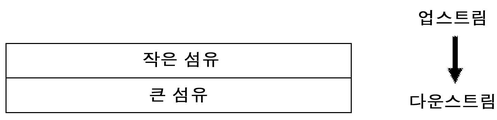
도 2a는 연속 미세 섬유층의 상이한 계층에서의 상이한 직경의 섬유들의 혼합물을 포함한 본원에 기술된 필터 매체의 연속 미세 섬유층의 예시적인 구현예의 개략도를 도시한 것이다. 도 2b는 500x 배율(상단 패널) 및 2000x 배율(하단 패널)의 나일론 스크림 상에 증착된 미세 섬유층을 포함하는 연속 미세 섬유층의 예시적인 이미지를 도시한 것이다. 도 2c는 실시예 3에 기술된 바와 같이 제조된 샘플(스크림 상에 직접 가로놓여 있는 작은 미세 섬유를 포함하는 연속 미세 섬유층)의 예시적인 SEM 이미지(1000x 배율)를 도시한 것이다. 도 2d는 실시예 3에 기술된 바와 같이 제조된 샘플(큰 미세 섬유 상에 오버레이된 작은 미세 섬유를 포함하는 연속 미세 섬유층)의 예시적인 SEM 이미지(1000x 배율)를 도시한 것이다. 도 2e는 작은 미세 섬유를 달성하기 위해 용액 1(좌측 패널), 혼합된(작은 및 큰) 직경의 혼합방사 미세 섬유를 달성하기 위해 용액 1 및 용액 2(중앙 패널), 및 큰 미세 섬유를 달성하기 위해 용액 2(우측 패널)를 사용하여 실시예 4에 기술된 바와 같이 제조된 연속 미세 섬유층 샘플의 예시적인 SEM 이미지(1000x 배율)를 도시한 것이다. 도 2f는 실시예 3에 기술된 바와 같이 제조된 샘플(스크림 상에 직접 가로놓인 작은 미세 섬유)에 대한 개략도를 도시한 것이다. 도 2g는 실시예 3에 기술된 바와 같이 제조된 연속 미세 섬유층 샘플(큰 미세 섬유 상에 오버레이드된 작은 미세섬유, 스크림 상에 직접 가로놓인 큰 미세 섬유)에 대한 개략도를 도시한 것이다. 도 2h 내지 도 2m은 예시적인 매체 구조의 개략도를 도시한 것이다. 각 구조에서, 지지층은 도시되어 있지 않지만, 통상적으로, 매체의 다운스트림 측면 상에 위치될 것이다. 각 구조에서, 효율층은 도시되어 있지 않지만, 통상적으로, 매체의 업스트림 측면 상에 위치될 것이다.
도 3a는 순환 흐름 조건(청색) 또는 정상 흐름 조건(적색) 하에서 3개의 상이한 매체에 대한 β 비율 대 입자 크기를 도시한 것이다. 좌측 패널: 10 마이크론(㎛) 효율 등급을 갖는 Donaldson Synteq XP™ 합성 액체 매체. 중간 패널: 5 마이크론 효율 등급을 갖는 Donaldson Synteq XP™ 합성 액체 매체. 우측 패널: 실시예 1에 기술된 필터 매체(XP/미세 섬유/스크림)(효율층(10 마이크론 효율 등급을 갖는 Donaldson Synteq XP™ 합성 액체 매체), 연속 미세 섬유층, 및 지지층(스크림)). 도 3b는 도 3a에서 시험된 동일한 매체에 대한 압력 강하를 도시한 것이다.
도 4는 10 마이크론 효율 등급을 갖는 Donaldson Synteq XP™ 합성 액체 매체(상단) 또는 실시예 2에 기술된 바와 같은 필터 매체(효율층(10 마이크론 효율 등급을 갖는 Donaldson Synteq XP™ 합성 액체 매체), 연속 미세 섬유층, 및 지지층)를 포함하는 필터 요소에 대한 정상 흐름 조건 하에서의 β 비율 대 입자 크기를 도시한 것이다. 베타 비율은 실시예에서 정상 흐름 조건 시험에 기술된 바와 같이 측정되었다. 슬래시로 구분된 3개의 숫자는 ISO 4406:2017에 기술된 바와 같이 측정 및 규정된, ISO(International Organization for Standardization) 청정도 코드를 나타낸다.
도 5는 10 마이크론 효율 등급을 갖는 Donaldson Synteq XP™ 합성 액체 매체(상단) 또는 실시예 2에 기술된 필터 매체(효율층(10 마이크론 효율 등급을 갖는 Donaldson Synteq XP™ 합성 액체 매체), 연속 미세 섬유층, 및 지지층)를 포함하는 필터 요소에 대한 순환 흐름 조건 하에서의 β 비율 대 입자 크기를 도시한 것이다. 베타 비율은 실시예에서 순환 흐름 조건에 기술된 바와 같이 측정되었다. 슬래시로 구분된 3개의 숫자는 ISO 4406:2017에 기술된 바와 같이 측정 및 규정된, ISO(International Organization for Standardization) 청정도 코드를 나타낸다.
도 6a 및 도 6b는 실시예 5에 추가로 기술된 바와 같이, 하나 이상의 연속 미세 섬유층 및 지지층을 포함하는 복합체에 대한 복합체 최대 기공 크기(도 6a) 또는 복합체 평균 흐름 기공 크기(도 6b)에 대해 플롯팅된 초기 압력 강하를 도시한 것이다. 삼각형은 시험 전반에 걸쳐 미세 섬유 구조적 무결성을 유지한 샘플을 나타내며, 사각형은 시험 동안 미세 섬유의 블로우-아웃을 겪은 샘플을 나타낸다.
도 7은 실시예 6에 기술된 샘플에 대한 누적 흐름 기공 크기 분포를 도시한 것이다.
도 8a는 지지층 상에 연속 미세 섬유층의 예시적인 단면 이미지를 도시한 것이다. 도 8b 내지 도 8d는 실시예에 추가로 기술된 바와 같이, 연속 미세 섬유층 두께를 측정하는 방법의 예시적인 이미지를 도시한 것이다.1A and 1B illustrate exemplary filter media and filter element structures, as further described herein.
2A shows a schematic diagram of an exemplary embodiment of a continuous fine fiber layer of a filter media described herein comprising a mixture of fibers of different diameters in different layers of the continuous fine fiber layer. 2B shows exemplary images of a continuous fine fiber layer comprising a layer of fine fibers deposited on a nylon scrim at 500x magnification (top panel) and 2000x magnification (bottom panel). 2C shows an exemplary SEM image (1000x magnification) of a sample prepared as described in Example 3 (a continuous microfiber layer comprising small microfibers directly overlaid on a scrim). 2D shows an exemplary SEM image (1000x magnification) of a sample prepared as described in Example 3 (a continuous microfiber layer comprising small microfibers overlaid on large microfibers). Figure 2e shows solution 1 (left panel) to achieve small microfibers,
Figure 3a shows the β ratio versus particle size for three different media under circulating flow conditions (blue) or normal flow conditions (red). Left panel: Donaldson Synteq XP™ synthetic liquid medium with 10 micron (μm) efficiency rating. Middle panel: Donaldson Synteq XP™ synthetic liquid medium with 5 micron efficiency rating. Right panel: filter media (XP/fine fibers/scrim) described in Example 1 (efficiency layer (Donaldson Synteq XP™ synthetic liquid media with 10 micron efficiency rating), continuous fine fiber layer, and backing layer (scrim)). Figure 3b shows the pressure drop for the same medium tested in Figure 3a.
4 shows Donaldson Synteq XP™ synthetic liquid media with 10 micron efficiency rating (top) or filter media as described in Example 2 (efficiency layer (Donalson Synteq XP™ synthetic liquid media with 10 micron efficiency rating), continuous The β ratio versus particle size under normal flow conditions for a filter element comprising a fine fiber layer, and a support layer) is shown. The beta ratio was determined as described in the Normal Flow Condition Test in the Examples. Three numbers separated by a slash represent the International Organization for Standardization (ISO) cleanliness code, measured and defined as described in ISO 4406:2017.
5 shows Donaldson Synteq XP™ synthetic liquid media with 10 micron efficiency rating (top) or filter media described in Example 2 (efficiency layer (Donalson Synteq XP™ synthetic liquid media with 10 micron efficiency rating), continuous fine fiber layer; , and a support layer) versus particle size versus β ratio under circulating flow conditions for a filter element. The beta ratio was determined as described in Circulating Flow Conditions in the Examples. Three numbers separated by a slash represent the International Organization for Standardization (ISO) cleanliness code, measured and defined as described in ISO 4406:2017.
6A and 6B are plots for composite maximum pore size (FIG. 6A) or composite average flow pore size (FIG. 6B) for a composite comprising one or more continuous microfiber layers and a support layer, as further described in Example 5; Plotted initial pressure drop is shown. Triangles represent samples that maintained microfiber structural integrity throughout the test, and squares represent samples that underwent blow-out of microfibers during testing.
7 shows the cumulative flow pore size distribution for the samples described in Example 6.
8A shows an exemplary cross-sectional image of a continuous microfiber layer on a support layer. 8B-8D show exemplary images of a method for measuring a continuous fine fiber layer thickness, as further described in the Examples.
본 개시내용은 압력 강하의 상응하는 증가, 즉, 필터 매체를 통해 유체를 강제로 통과시키는 데 필요한 압력의 증가 없이 필터 매체 효율에 대한 유량 변화(예를 들어, 동적 흐름 조건 동안 일어남)의 역효과를 최소화하는 필터 매체를 기술한다. 본 개시내용은 또한 필터 매체를 제조하는 방법을 기술한다.The present disclosure addresses the adverse effect of a change in flow rate (e.g., that occurs during dynamic flow conditions) on filter media efficiency without a corresponding increase in pressure drop, i.e., an increase in the pressure required to force the fluid through the filter media. Describe the filter media that minimizes it. The present disclosure also describes a method of making a filter media.
동적 흐름 조건에 대한 필터 매체의 설계의 과제Challenges in the design of filter media for dynamic flow conditions
본 개시내용은 압력 강하의 상응하는 증가 없이 필터 매체 효율에 대한 유량 변화의 역효과를 최소화하는 필터 매체를 기술한다. 이러한 유량 변화는 예를 들어, 동적 흐름 조건 동안에 일어날 수 있다. 동적 흐름 조건은 예를 들어, 순환 흐름 조건을 포함한다. 그러나, 본원에서 추가로 논의되는 바와 같이, 필터 매체 설계는 또한, 다른 액체 적용에서 성능을 개선시키기 위해 사용될 수 있다.This disclosure describes filter media that minimize the adverse effect of flow rate changes on filter media efficiency without a corresponding increase in pressure drop. Such flow rate changes may occur, for example, during dynamic flow conditions. Dynamic flow conditions include, for example, cyclic flow conditions. However, as discussed further herein, the filter media design can also be used to improve performance in other liquid applications.
효율을 유일한 성능 기준으로 하여 필터가 설계된 경우에, 모든 여과 요구를 쉽게 해결할 수 있을 것이다. 그러나, 대부분의 적용의 경우, 압력 및 필터 수명이 또한 고려되어야 하고, 원하는 효율에 대해 균형을 이루어야 한다.If a filter was designed with efficiency as the sole performance criterion, it would be easy to address all filtration needs. However, for most applications, pressure and filter life must also be considered and balanced against the desired efficiency.
예를 들어, 0.5 ㎛보다 큰 모든 입자 100%를 제거할 수 있는 필터를 설계하는 것은 쉽지만, 이러한 필터 설계는, 필터를 통해 유체를 밀어내는 데 필요한 압력이 비합리적으로 높은 수준이거나 필터가 실용적이지 않게 짧은 간격으로 교체되어야 한다면 실용적이지 않을 것이다. 더욱 특정의 예에서, 자동차의 오일 필터가 엔진을 완벽하게 깨끗하게 유지하더라도, 필터를 통해 유체를 밀어 내기 위해 필터가 엔진 동력의 대부분을 필요로 하고 차량에 연료를 재공급할 때마다 교체해야 하는 경우, 이는 상업적으로 그리고 실제적으로 실현 불가능할 것이다.For example, it is easy to design a filter that can remove 100% of all particles larger than 0.5 μm, but such a filter design would either require an unreasonably high level of pressure to force the fluid through the filter or make the filter impractical. It would be impractical if they had to be replaced at short intervals. In a more specific example, even if a car's oil filter keeps the engine perfectly clean, the filter requires most of the engine's power to force fluid through the filter and must be replaced each time the vehicle is refueled; This would be commercially and practically impractical.
본원에 기술된 필터 매체가 효율 성능을 어떻게 개선시키는지의 예시를 제공하기 위해, 먼저 필터 매체가 오염물을 수집하는 방법 및 수집이 필터 매체를 통해 유체가 흐를 때 필터 매체에 대해 압력에 미치는 영향을 기술하는 것이 도움이 된다.To provide an example of how the filter media described herein improve efficiency performance, first describe how the filter media collects contaminants and how collection affects the pressure on the filter media as a fluid flows through the filter media. it helps to
필터 매체는 필터 매체의 성분들 사이에 공간을 포함하며, 이는 또한, 필터 매체의 최상부 표면 상에 오염물을 수집할 수 있다. 오염물이 상단 필터 매체에 또는 상단 필터 매체 상의 공간에 수집됨에 따라, 필터 매체를 가로질러 유체를 밀어 내는 데 필요한 압력은 유체가 통과하는 공간이 작아지고 그 수가 적어지기 때문에 증가한다. 작업 액체 필터 매체(특히, 유압식에서)의 수명 종료는 대개 특정 액체 흐름이 필터 매체를 통과하는 동안 생성되는 최대 압력에 의해 규정된다. 이에 따라, 오염물이 수집될수록, 압력 강하는 증가하며, 필터 매체의 다공도, 즉 전체 체적에 대한 다공성 매체에서의 공간의 체적의 비율은 감소한다.The filter medium includes spaces between the components of the filter medium, which can also collect contaminants on the top surface of the filter medium. As contaminants collect in or into the space on the upper filter media, the pressure required to force the fluid across the filter media increases as the space through which the fluid passes becomes smaller and smaller in number. The end of life of a working liquid filter medium (especially in hydraulics) is usually dictated by the maximum pressure produced while a particular liquid stream passes through the filter medium. Accordingly, as contaminants are collected, the pressure drop increases and the porosity of the filter medium, ie the ratio of the volume of space in the porous medium to the total volume, decreases.
다공도가 감소할수록, 이는 압력 강하에 대한 지배적인 기여자가 되며, 이에 따라, 액체 필터에 대한 수명 종료를 규정하는 주요 파라미터가 된다. 이에 따라, 유압 필터 매체에서 더 긴 수명을 달성하기 위해, 필터 매체에 의해 오염물이 수집되는 방법을 관리하는 것이 바람직하다. 오염물을 단일 위치(예를 들어, 매체의 표면 상)에 수집되는 것과는 반대로, 오염물이 수집되는 위치를 분산시킴(예를 들어, 매체의 깊이를 통해 이용 가능한 더 많은 공간을 확보함에 의한 것을 포함함)은 필터 매체의 다공성을 더 오래 유지시키고, 매체를 통해 액체를 통과시키는 데 필요한 압력을 감소시키고, 필터 매체의 수명을 연장시킨다. 매체 깊이에 걸쳐 오염물이 수집되는 위치를 분산시키는 필터 매체 설계는 깊이 로딩 필터 매체로 불리워진다.As the porosity decreases, it becomes the dominant contributor to the pressure drop and, thus, a key parameter defining the end-of-life for liquid filters. Accordingly, in order to achieve a longer life in hydraulic filter media, it is desirable to control how contaminants are collected by the filter media. Dispersing the locations where contaminants are collected (including, for example, by making more space available through the depth of the medium) as opposed to collecting contaminants in a single location (e.g., on the surface of the medium) ) maintains the porosity of the filter media longer, reduces the pressure required to pass liquid through the media, and extends the life of the filter media. Filter media designs that distribute the locations where contaminants are collected across the media depth are called depth loading filter media.
필터 매체의 깊이 전반에 걸쳐 더 높은 다공성은 필터 매체를 사용하는 동안 오염물을 수집할 수 있는 더 많은 공간을 허용한다. 가상적으로 가장 오래 지속되는 필터 매체는 100% 다공성인 매체이다. 그러나, 이러한 장점은 단지 가설인데, 왜냐하면, 체적의 일부분이 오염물을 포착하고 유지하기 위해 무엇인가에 의해 채워져야 하기 때문이다. 이에 따라, 원하는 효율 및 강도를 달성하는 데 필요한 특성을 갖는 필터 물질을 제공하면서 가능한 한 높은 다공성을 갖는 것이 바람직하다.Higher porosity throughout the depth of the filter media allows more space to collect contaminants during use of the filter media. Virtually the longest lasting filter media are those that are 100% porous. However, this advantage is only hypothetical, since a portion of the volume must be filled by something to trap and retain contaminants. Accordingly, it is desirable to have as high a porosity as possible while providing a filter material with the necessary properties to achieve the desired efficiency and strength.
액체 유압 여과에서, 주요 여과 메커니즘은 크기 배제이다. 크기 배제 동안, 오염물은, 오염물의 치수보다 더 작은 치수를 갖는 기공에 트랩핑될 때 필터 매체에 의해 포집된다. 필터 매체의 깊이 전반에 걸쳐 분포된, 기공 크기의 넓은 분포는 필터 매체의 두께 내에서 오염물의 분포를 허용한다. 기공들은 무작위로 이격될 수 있거나, 이러한 것들은 구배 또는 다른 패턴 구조를 형성할 수 있다. 패턴(또는 이의 결여)에 관계없이, 원하는 효과는 필터 매체의 깊이를 통해 가능한 한 많은 오염물을 분산시키는 것이다.In liquid hydraulic filtration, the main filtration mechanism is size exclusion. During size exclusion, contaminants are entrapped by the filter media as they become trapped in pores having dimensions smaller than the dimensions of the contaminants. A broad distribution of pore sizes, distributed throughout the depth of the filter medium, allows for the distribution of contaminants within the thickness of the filter medium. The pores may be randomly spaced, or they may form a gradient or other patterned structure. Regardless of the pattern (or lack thereof), the desired effect is to disperse as much contaminant as possible through the depth of the filter medium.
크기 배제에 의한 수집을 위해 설계된 필터 매체는 실험실 시험에서 정상 흐름 조건 하에서 잘 작동하는 것으로 나타났다. 그러나, 대부분의 유압 흐름 적용에서, 필터 매체를 통한 유량은 가변적이고, 순환 흐름 패턴을 가질 수 있다. 이러한 가변 흐름 조건 동안, 가장 통상적으로 동적 힘으로 불리워지는 변화하는 힘은 필터 매체 구조 및 필터 매체에 의해 포집된 오염물 둘 모두에 적용된다. 이러한 동적 힘은 필터 매체가 오염물을 포집하는 방식을 변경하여 전체 효율을 감소시킨다.Filter media designed for collection by size exclusion have been shown to work well under normal flow conditions in laboratory tests. However, in most hydraulic flow applications, the flow rate through the filter medium is variable and can have a circulating flow pattern. During these variable flow conditions, a varying force, most commonly referred to as a dynamic force, is applied to both the filter media structure and the contaminants captured by the filter media. These dynamic forces alter the way the filter media captures contaminants, reducing overall efficiency.
이론에 의해 얽매이고자 하는 것은 아니지만, 상이한 힘이 필터 매체에 적용될 때 재방출되는 오염물의 치수보다 더 작은 치수를 갖는 기공에서 이전에 트랩핑된 오염물로 인해 가변 흐름 조건 동안 관찰된 전체 효율의 감소가 발생하는 것으로 여겨진다.While not wishing to be bound by theory, the decrease in overall efficiency observed during variable flow conditions due to previously trapped contaminants in pores having dimensions smaller than those of re-emitted contaminants when different forces are applied to the filter media may be is believed to occur
결과적으로, 정상 흐름 조건 하에서 특정 효율 성능에 대해 등급화된 필터는 종종 가변(예를 들어, 순환) 흐름 조건 동안에 성능 저하되며, 이러한 필터는 더 많은 오염물이 필터를 통해 다운스트림 출력으로 통과되도록 한다. 필터의 다운스트림에서 오염물의 증가는 유압 시스템의 마모 증가 및/또는 중요한 유압 부품의 수명 단축을 야기시킬 수 있다.As a result, filters rated for a particular efficiency performance under normal flow conditions often degrade during variable (e.g., circulating) flow conditions, such filters allow more contaminants to pass through the filter to the downstream output. . An increase in contaminants downstream of the filter can cause increased wear of the hydraulic system and/or shortened life of critical hydraulic components.
이에 따라, 이러한 유압 시스템의 사용자는 가변 흐름 조건 하에서 신뢰성 있게 수행되도록 설계된 유압유 여과 매체를 갖는 것이 바람직하다.Accordingly, it is desirable for users of such hydraulic systems to have hydraulic oil filtration media designed to perform reliably under variable flow conditions.
가변 흐름 조건 하에서 매체의 효율을 증가시키는 하나의 수단은 필터 매체의 두께를 증가시키는 것이다. 증가된 두께(또는 깊이)를 제공함으로써, 특정 오염물을 포착할 수 있는 더 많은 기회가 제공된다. 그러나, 필터 매체가 너무 두꺼워지면, 이는 전통적인 주름진 구성과 같이, 한정된 공간에 이를 패킹하기 어렵게 된다. 또한, 특정 오염물을 포획할 확률이 두께를 증가시킴으로써 개선되더라도, 오염물은 여전히 매체를 통과할 수 있다.One means of increasing the efficiency of the media under variable flow conditions is to increase the thickness of the filter media. By providing increased thickness (or depth), more opportunities are provided to capture certain contaminants. However, if the filter media becomes too thick, it becomes difficult to pack it in confined spaces, such as in traditional pleated constructions. Also, although the probability of capturing certain contaminants is improved by increasing the thickness, contaminants can still pass through the medium.
가변 흐름 조건 하에서 매체의 효율을 증가시키는 다른 수단은 필터 매체의 기공 크기를 감소시키는 것이다. 그러나, 상기에 주지된 바와 같이, 기공 크기를 줄이면 필터 매체가 용량 한도에 더 빨리 도달하게 한다. 또한, 더 작은 기공 크기는 오염물이 포집되기 전에 액체를 매체를 통해 통과시키는 데 더 큰 압력이 필요하게 할 수 있고, 특정 체적의 오염물이 포집된 후 액체를 매체를 통해 통과시키는 데 확실히 더 큰 압력을 야기할 것이다.Another means of increasing the efficiency of the media under variable flow conditions is to reduce the pore size of the filter media. However, as noted above, reducing the pore size allows the filter media to reach its capacity limit more quickly. Also, a smaller pore size may require a greater pressure to pass the liquid through the medium before contaminants are captured, and a significantly greater pressure to pass the liquid through the medium after a certain volume of contaminants has been captured. will cause
본원에 기술된 필터 매체는 다층 구조를 제공함으로써 이러한 한계를 극복하고자 한다. 개별적으로 각 층이 불량한 성능을 가질 수 있지만, 층의 오염은 가변 흐름 조건(예를 들어, 순환 흐름 조건을 포함함) 하에서 개선된 성능을 제공한다.The filter media described herein seek to overcome this limitation by providing a multi-layer structure. Although each layer individually may have poor performance, contamination of the bed provides improved performance under variable flow conditions (eg, including circulating flow conditions).
필터 매체filter medium
일 양태에서, 본 개시내용은 지지층, 연속 미세 섬유층, 및 효율층을 포함하는 필터 매체를 기술한다. 일부 구현예에서, 연속 미세 섬유층은 효율층과 지지층 사이에 위치되며, 효율층은 필터 매체의 업스트림 측면 상에 위치된다. 일부 구현예에서, 연속 미세 섬유층은 표면 로딩층으로서 작용한다. 일부 구현예에서, 효율층은 깊이-로딩층으로서 작용한다.In one aspect, the present disclosure describes a filter media comprising a support layer, a continuous fine fiber layer, and an efficiency layer. In some embodiments, a continuous fine fiber layer is positioned between the efficiency layer and the support layer, and the efficiency layer is positioned on the upstream side of the filter medium. In some embodiments, the continuous fine fiber layer acts as a surface loading layer. In some embodiments, the efficiency layer acts as a depth-loading layer.
상기에 주지된 바와 같이, 깊이-로딩층 단독은 이의 낮은 강도 및 넓은 기공 크기 분포로 인해 가변 흐름 조건 하에서 불량한 효율을 갖는다. 연속 미세 섬유층 단독은, 필터 매체를 통해 액체를 통과시키는 데 필요한 압력이 오염물이 수집되는 거의 즉시 증가하기 시작하기 때문에 표면 로딩층으로서 작용하는 경우 가변 흐름 조건 하에서 매우 짧은 수명을 가질 것이다. 그리고, 지지층 단독은 이의 효율이 실제적으로 존재하지 않기 때문에 가변 흐름 조건 하에서 필터 매체로서 사용하기에 적절하지 않을 것이다.As noted above, the depth-loading layer alone has poor efficiency under variable flow conditions due to its low strength and broad pore size distribution. A continuous fine fiber layer alone will have a very short lifetime under variable flow conditions when acting as a surface loading layer because the pressure required to pass liquid through the filter medium begins to increase almost immediately as contaminants are collected. And, the support layer alone would not be suitable for use as a filter medium under variable flow conditions because its efficiency would not be practically present.
그러나, 본원에 추가로 기술된 바와 같이 선택된 특징과 조합하여, 지지층, 연속 미세 섬유층, 및 효율층은 필터 매체 효율에 대한 가변 흐름 조건의 역효과를 최소화하고, 상업적으로 또는 실제적으로 실행 불가능한 압력 강하 증가를 나타내지 않는 필터 매체를 제공한다.However, in combination with selected features as further described herein, the support layer, continuous fine fiber layer, and efficiency layer minimize the adverse effect of variable flow conditions on filter media efficiency and increase pressure drop that is commercially or practically impractical. A filter medium that does not exhibit
예를 들어, 본원에 추가로 기술되는 바와 같이, 표면 로딩층으로서 작용하는 연속 미세 섬유층은 입자가 필터 매체를 통과하는 것을 방지한다. 추가적으로, 연속 미세 섬유층이 매우 얇기 때문에, 이는 두꺼운 매체만큼 압력 강하를 증가시키지 않는다. 또한, 연속 미세 섬유층을 적절한 저강도 층(즉, 깊이 로딩층으로서 작용하는 효율층)과 조합함으로써, 필터 매체의 수명이 연장될 수 있다.For example, as further described herein, a continuous fine fiber layer acting as a surface loading layer prevents particles from passing through the filter media. Additionally, because the continuous microfiber layer is very thin, it does not increase the pressure drop as much as the thick media. Also, by combining the continuous fine fiber layer with a suitable low strength layer (ie, an efficiency layer acting as a depth loading layer), the life of the filter media can be extended.
필터 매체의 추가적인 선택적 구성Additional optional configuration of filter media
상기에 주지된 바와 같이, 필터 매체는 연속 미세 섬유층 및 효율층을 포함한다. 그러나, 일부 구현예에서, 필터 매체는 다수의 연속 미세 섬유층 및 다수의 효율층을 포함할 수 있다. 예를 들어, 일 구현예에서, 필터 매체는 필터 매체의 업스트림 측면 상에 위치된 제1 효율층, 제1 효율층의 다운스트림 측면 상에 위치된 제1 연속 미세 섬유층, 제1 연속 미세 섬유층의 다운스트림 측면 상에 위치된 제2 효율층, 및 제2 효율층의 다운스트림 측면 상에 위치된 제2 미세 섬유층을 포함할 수 있다. 지지층은 통상적으로, 가장 다운스트림에 있는 연속 미세 섬유층의 다운스트림 측면 상에 위치될 것이다(도 1b, 좌측 패널 참조).As noted above, the filter media comprises a continuous fine fiber layer and an efficiency layer. However, in some embodiments, the filter media may include multiple layers of continuous fine fibers and multiple layers of efficiency. For example, in one embodiment, the filter medium comprises a first efficiency layer located on an upstream side of the filter medium, a first continuous fine fiber layer located on a downstream side of the first efficiency layer, a first continuous fine fiber layer a second efficiency layer positioned on the downstream side, and a second fine fiber layer positioned on the downstream side of the second efficiency layer. The backing layer will typically be located on the downstream side of the most downstream continuous fine fiber layer (see FIG. 1B , left panel).
예를 들어, 다른 구현예에서, 필터 매체는 필터 매체의 업스트림 측면 상에 위치된 제1 효율층, 제1 효율층의 다운스트림 측면 상에 위치된 제1 연속 미세 섬유층, 제1 연속 미세 섬유층의 다운스트림 측면 상에 위치된 제2 효율층, 제2 효율층의 다운스트림 측면 상에 위치된 제2 미세 섬유층, 제1 연속 미세 섬유층의 다운스트림 측면 상에 위치된 제3 효율층, 및 제3 효율층의 다운스트림 측면 상에 위치된 제3 연속 미세 섬유층을 갖는다. 지지층은 통상적으로, 가장 다운스트림 연속 미세 섬유층의 다운스트림 측면 상에 위치될 것이다(도 1b, 중간 패널 참조).For example, in another embodiment, the filter medium comprises a first efficiency layer located on an upstream side of the filter medium, a first continuous fine fiber layer located on a downstream side of the first efficiency layer, a first continuous fine fiber layer a second efficiency layer located on the downstream side, a second fine fiber layer located on the downstream side of the second efficiency layer, a third efficiency layer located on the downstream side of the first continuous fine fiber layer, and a third and a third continuous fine fiber layer located on the downstream side of the efficiency layer. The backing layer will typically be located on the downstream side of the most downstream continuous fine fiber layer (see FIG. 1B , middle panel).
일부 구현예에서, 필터 매체는 필터 매체의 업스트림 측면 상에 위치된 하나 초과의 효율층, 및 효율층의 다운스트림 측면 상에 위치된 연속 미세 섬유층을 포함할 수 있다(도 1b, 우측 패널 참조). 추가적인 효율층은 예를 들어, 필터 매체의 용량(및 이에 따라, 수명)을 증가시키거나 압력 강하를 개선시키기 위해 사용될 수 있다. 이러한 추가적인 효율층은 또한, 로딩층으로서 지칭될 수 있다. 지지층, 연속 미세 섬유층, 효율층, 및 제2 효율층(또는 로딩층)을 포함하는 필터 매체의 예시적인 구현예는 실시예 6에 기술되고 특성규명한다.In some embodiments, the filter media may include more than one efficiency layer positioned on an upstream side of the filter media, and a continuous fine fiber layer positioned on a downstream side of the efficiency layer (see FIG. 1B , right panel). . The additional efficiency layer can be used, for example, to increase the capacity (and thus lifespan) of the filter medium or to improve the pressure drop. This additional efficiency layer may also be referred to as a loading layer. An exemplary embodiment of a filter media comprising a support layer, a continuous fine fiber layer, an efficiency layer, and a second efficiency layer (or loading layer) is described and characterized in Example 6.
필터 매체의 특징Characteristics of filter media
일부 구현예에서, 본원에 기술된 필터 매체는 압력 강하를 손상시키지 않으면서 연속 미세 섬유층 또는 층들이 없는 매체와 비교하여 효율 증가를 달성하며, 즉, 본원에 기술된 필터 매체의 압력 강하는 연속 미세 섬유층 또는 층들이 없는 필터 매체의 압력 강하의 150% 이내, 100% 이내, 50% 이내, 20% 이내, 15% 이내, 또는 10% 이내이다.In some embodiments, the filter media described herein achieve an increase in efficiency compared to media without a continuous fine fiber layer or layers without compromising pressure drop, i.e., the pressure drop of the filter media described herein is within 150%, within 100%, within 50%, within 20%, within 15%, or within 10% of the pressure drop of the filter media without the fibrous layer or layers.
일부 구현예에서, 본원에 기술된 필터 매체는 연속 미세 섬유층 또는 층들이 없고 압력 강하를 손상시키지 않는 지지층이 없는 매체와 비교하여 효율 증가를 달성하며, 즉, 본원에 기술된 필터 매체의 압력 강하는 연속 미세 섬유층 또는 층들이 없고 지지층이 없는 필터 매체의 압력 강하의 150% 이내, 100% 이내, 50% 이내, 20% 이내, 15% 이내, 또는 10% 이내이다.In some embodiments, the filter media described herein achieve an increase in efficiency compared to media without a continuous fine fiber layer or layers and without a support layer that does not impair the pressure drop, i.e., the pressure drop of the filter media described herein is Within 150%, within 100%, within 50%, within 20%, within 15%, or within 10% of the pressure drop of the filter medium without a continuous fine fiber layer or layers and without a support layer.
예를 들어, 예시적인 구현예에서, 필터 매체의 압력 강하는 효율층 또는 층들 단독에 의해 관찰된 압력 강하(즉, 연속 미세 섬유층 또는 층들이 없고 지지층이 없는 필터 매체의 압력 강하)의 50% 내지 150%의 범위 이내이다.For example, in an exemplary embodiment, the pressure drop of the filter medium is from 50% to 50% of the pressure drop observed with the efficiency layer or layers alone (ie, the pressure drop of a filter medium without a continuous fine fiber layer or layers and no support layer). It is within the range of 150%.
일부 구현예에서, 본원에 기술된 필터 매체는 정상 흐름 조건 하에서 연속 미세 섬유층이 없는 매체와 비교하여 순환 흐름 조건 하에서 동등한 효율을 달성한다. 바람직하게는, 이러한 효율은 상당한 압력 강하 페널티 없이 달성된다. 예를 들어, 압력 강하는 연속 미세 섬유층 또는 층들이 없는 및 지지층이 없는 필터 매체의 압력 강하의 150% 이내, 100% 이내, 50% 이내, 20% 이내, 15% 이내, 또는 10% 이내에 속한다.In some embodiments, the filter media described herein achieve equivalent efficiencies under circulating flow conditions as compared to media without a continuous fine fiber layer under normal flow conditions. Preferably, this efficiency is achieved without significant pressure drop penalties. For example, the pressure drop falls within 150%, within 100%, within 50%, within 20%, within 15%, or within 10% of the pressure drop of the filter media without a continuous fine fiber layer or layers and without a support layer.
일부 구현예에서, 본원에 기술된 필터 매체는 순환 흐름 조건 하에서 적어도 5, 적어도 7, 또는 적어도 10의 전체 β10 ㎛를 나타낸다. 필터 매체는 최대 50, 최대 100, 최대 200, 최대 300, 최대 500, 최대 1000, 최대 1500, 또는 최대 2000의 전체 β10 ㎛를 추가로 나타낼 수 있다. 예를 들어, 전체 β10 ㎛는 5 내지 2000 범위, 5 내지 200 범위, 또는 5 내지 100 범위일 수 있다.In some embodiments, the filter media described herein exhibit an overall β 10 μm of at least 5, at least 7, or at least 10 under circulating flow conditions. The filter medium may further exhibit an overall β 10 μm of at most 50, at most 100, at most 200, at most 300, at most 500, at most 1000, at most 1500, or at most 2000. For example, the total β 10 μm can range from 5 to 2000, from 5 to 200, or from 5 to 100.
순환 흐름 조건은 플랫 시트 성능을 시험할 때를 제외하고 ISO/CD 23369 Edition 1을 이용하여 평가될 수 있으며, 시험은 단일패스 모드에서 실행되며, 시험은 25℃에서 실행되어야 한다. 매체를 통한 유속은 10초 사이클에서 5 mm/초 내지 1.25 mm/초 사이에서 사이클링될 수 있다. ISO 12103-1, Medium Test Dust는 입자로서 유용할 수 있다. 10 mg/L의 업스트림 입자 농도가 사용될 수 있다. 연속 입자 농도 측정은 6초마다 수집될 수 있다. 이는 1000 피코지멘스(picosiemens)/미터(pS/m) 내지 1500 pS/m 범위까지 유체 전도도를 제어하는 데 유용할 수 있다.Cyclic flow conditions can be evaluated using ISO/CD 23369
일부 구현예에서, 필터 매체의 섬유 중 하나 이상은 필터 매체의 정전기 전하를 변경하기 위해 선택 또는 처리될 수 있다. 전하는 통상적으로, 폴리머의 표면에 또는 부근에 트랩핑된 양전하 또는 음전하의 층, 또는 폴리머의 벌크에 저장된 전하 클라우드를 포함한다. 전하는 또한, 분자의 쌍극자의 정렬로 동결된 분극 전하를 포함할 수 있다. 물질을 전기 전하로 처리하는 방법은 당업자에 의해 널리 공지되어 있다. 이러한 방법은 예를 들어, 열적, 액체-접촉, 전자빔, 플라즈마, 및 코로나 방전 방법을 포함한다.In some embodiments, one or more of the fibers of the filter media may be selected or treated to alter the electrostatic charge of the filter media. The charge typically comprises a layer of positive or negative charges trapped at or near the surface of the polymer, or a cloud of charges stored in the bulk of the polymer. Charges can also include polarized charges frozen in the alignment of the dipoles of the molecule. Methods of treating materials with an electrical charge are well known to those skilled in the art. Such methods include, for example, thermal, liquid-contact, electron beam, plasma, and corona discharge methods.
지지층 및 연속 미세 섬유층 복합체의 평균 최대 기공 크기 및 평균 중간 흐름 기공 크기Average Maximum Pore Size and Average Median Flow Pore Size of Backing Layer and Continuous Fine Fiber Layer Composites
상기에 기술된 바와 같이, 필터 매체는 지지층 및 연속 미세 섬유층을 포함한다. 일부 구현예에서, 연속 미세 섬유층은 다수의 연속 미세 섬유층을 포함할 수 있다. 이러한 지지층 및 연속 미세 섬유층 또는 층들은 복합체를 형성할 수 있다. 복합체는 적어도 하나의 연속 미세 섬유층을 포함한다.As described above, the filter media includes a support layer and a continuous fine fiber layer. In some embodiments, the continuous fine fiber layer may include multiple continuous fine fiber layers. Such a support layer and a continuous fine fiber layer or layers may form a composite. The composite comprises at least one continuous layer of fine fibers.
일부 구현예에서, 필터 매체는 최대 20 ㎛, 바람직하게는, 최대 15 ㎛, 및 더욱 바람직하게는, 최대 14 ㎛의 복합체 평균 최대 기공 크기를 갖는다. 일부 구현예에서, 필터 매체의 복합체 최대 기공 크기는 적어도 0.1 ㎛이다. 본원에서 사용되는 "복합체 평균 최대 기공 크기"는 지지층에 인접한 층에 존재하는 지지층 및 임의의 연속 미세 섬유층을 포함하는 복합체의 평균 최대 기공 크기를 지칭한다.In some embodiments, the filter media has a composite mean maximum pore size of at most 20 μm, preferably at most 15 μm, and more preferably at most 14 μm. In some embodiments, the composite maximum pore size of the filter media is at least 0.1 μm. As used herein, “composite average maximum pore size” refers to the average maximum pore size of a composite comprising a support layer present in a layer adjacent to the support layer and an optional continuous fine fiber layer.
일부 구현예에서, 필터 매체는 최대 11 ㎛, 바람직하게는, 최대 9 ㎛, 및 더욱 바람직하게는, 최대 6 ㎛의 복합체 평균 중간 흐름 기공 크기 또는 P50을 갖는다. 일부 구현예에서, 필터 매체의 복합체 평균 중간 흐름 기공 크기 또는 P50는 적어도 0.1 ㎛이다. 본원에서 사용되는 "복합체 평균 중간 흐름 기공 크기"는 지지층 및 지지층에 인접한 층에 존재하는 임의의 연속 미세 섬유층을 포함하는 복합체의 평균 중간 흐름 기공 크기를 지칭한다.In some embodiments, the filter media has a composite average median flow pore size or P50 of at most 11 μm, preferably at most 9 μm, and more preferably at most 6 μm. In some embodiments, the composite average median flow pore size or P50 of the filter media is at least 0.1 μm. As used herein, “composite average median flow pore size” refers to the average median flow pore size of a composite comprising a support layer and any continuous fine fibrous layer present in a layer adjacent to the support layer.
일부 구현예에서, 복합체 평균 최대 기공 크기 및/또는 복합체 평균 중간 흐름 기공 크기는 바람직하게는, 모세관 흐름 기공측정법을 이용하여 결정된다.In some embodiments, the composite average maximum pore size and/or the composite average median flow pore size is preferably determined using capillary flow porosimetry.
이론에 의해 얽매이고자 하는 것은 아니지만, 다른 인자들 중에서, 복합체 평균 최대 기공 크기 및 복합체 평균 중간 흐름 기공 크기가 미세 섬유 직경, 작은 및 큰 미세 섬유의 상대적 양, 및 복합체 모폴로지(예를 들어, 층상 또는 혼합방사)에 따라 달라지는 것으로 여겨진다.While not wishing to be bound by theory, among other factors, the composite average maximum pore size and composite average median flow pore size depend on the microfiber diameter, the relative amounts of small and large microfibers, and the composite morphology (e.g., lamellar or mixed spinning).
일부 구현예에서, 복합체는 효율층의 평균 흐름 기공 크기와 유사한 평균 흐름 기공 크기를 가질 수 있다. 예를 들어, 일부 구현예에서, 복합체의 평균 흐름 기공 크기(P50)는 인접한 효율층의 평균 흐름 기공 크기(P50)의 1%, 2%, 3%, 5%, 10%, 20%, 30%, 50%, 100%, 또는 200% 이내일 수 있다.In some embodiments, the composite may have an average flow pore size similar to the average flow pore size of the efficiency layer. For example, in some embodiments, the average flow pore size (P50) of the composite is 1%, 2%, 3%, 5%, 10%, 20%, 30% of the average flow pore size (P50) of an adjacent efficiency layer. %, 50%, 100%, or 200%.
실시예 5에 기술된 바와 같이, 필터 매체의 복합체 평균 최대 기공 크기는 액체 여과 동안 필터 매체가 적어도 20 psi 압력 강하를 견디는 능력과 상관관계가 있을 수 있는데, 이는 동일한 조건을 견딜 수 없는 필터 매체보다 더 양호한 필터 성능을 나타낸다.As described in Example 5, the composite average maximum pore size of a filter media can correlate with the filter media's ability to withstand at least a 20 psi pressure drop during liquid filtration, which is greater than a filter media that cannot withstand the same conditions. It shows better filter performance.
필터 매체의 복합체 평균 최대 기공 크기가 액체 여과 동안 필터 매체가 적어도 20 psi 압력 강하를 견디는 능력과 상관관계가 있을 수 있지만, 복합체 평균 최대 기공 크기는 때때로, 매체가 결함 또는 일반적이지 않은 큰 최대 기공을 포함하는 경우 부합되지 않는 값을 제공한다. 이에 따라, 복합체의 기공 크기 범위 및 기공 크기 분포를 더 잘 이해하기 위해, 하기에 기술되는 바와 같이 추가적인 값이 또한 시험되었다.Although the composite average maximum pore size of a filter media can correlate with the filter media's ability to withstand at least a 20 psi pressure drop during liquid filtration, the composite average maximum pore size sometimes If included, it provides an inconsistent value. Accordingly, to better understand the pore size range and pore size distribution of the composite, additional values were also tested as described below.
지지층 및 연속 미세 섬유층을 포함하는 복합체의 P95/P50 비율P95/P50 Ratio of Composite with Backing Layer and Continuous Fine Fiber Layer
일부 구현예에서, 지지층 및 연속 미세 섬유층으로부터 형성된 복합체는 최대 1.8, 최대 1.9, 또는 최대 2의 P95/P50 비율을 갖는다.In some embodiments, the composite formed from the support layer and the continuous fine fiber layer has a P95/P50 ratio of at most 1.8, at most 1.9, or at most 2.
미세 섬유층의 기공 크기가 복합체의 P95/P50 비율의 대부분의 값을 제어하지만, 지지층과 연속 미세 섬유층 간의 상호작용은 또한 성능에 영향을 미친다. 이론에 의해 얽매이고자 하는 것은 아니지만, 이러한 상호작용은 복합체 기공 크기 측정을 미세 섬유층 단독의 기공 크기 측정보다 더욱 유용하게 만들 것으로 여겨진다.Although the pore size of the fine fiber layer controls most values of the P95/P50 ratio of the composite, the interaction between the support layer and the continuous fine fiber layer also affects performance. While not wishing to be bound by theory, it is believed that these interactions will make composite pore sizing measurements more useful than pore sizing measurements of microfiber layers alone.
P50의 값은 유체의 50%가 그러한 직경 이하의 기공을 통해 흐르는 기공의 직경을 반영한다. P95의 값은 유체의 95%가 그러한 직경 이하의 기공을 통해 흐르는 기공의 직경을 반영하며, 더 큰 P95/P50의 비율은 일반적으로, 비교적 더 큰 기공이 존재하고 기공 크기의 범위가 더 큼을 반영한다.The value of P50 reflects the diameter of the pores through which 50% of the fluid flows through pores of that diameter or less. A value of P95 reflects the diameter of the pores through which 95% of the fluid flows through pores below that diameter, and a larger P95/P50 ratio generally reflects the presence of relatively larger pores and a greater range of pore sizes. do.
이론에 의해 얽매이고자 하는 것은 아니지만, 2보다 큰 P95/P50 비율을 갖는 복합체가 순환 흐름 하에서 충분한 효율을 제공하지 않을 것으로 여겨진다. 2 미만의 P95/P50 비율이 (강도 증가로 인해) 압력 강하의 증가를 제공하지만, 연속 미세 섬유층이 매우 얇기 때문에(예를 들어, 50 ㎛ 미만), 상응하는 압력 강하는 허용 가능한 한계 내에서 유지될 수 있다.Without wishing to be bound by theory, it is believed that composites with a P95/P50 ratio greater than 2 will not provide sufficient efficiency under circulating flow. A P95/P50 ratio of less than 2 provides an increase in pressure drop (due to increased strength), but since the continuous fine fiber layer is very thin (eg less than 50 μm), the corresponding pressure drop remains within acceptable limits. can be
일부 구현예에서, 복합체는 적어도 1의 P95/P50 비율을 갖는다.In some embodiments, the complex has a P95/P50 ratio of at least 1.
미세 섬유층에 인접한 효율층의 P95/P50 비율P95/P50 ratio of the efficiency layer adjacent to the fine fiber layer
일부 구현예에서, 효율층은 적어도 1.8, 적어도 1.9, 또는 적어도 2의 P95/P50 비율을 갖는다.In some embodiments, the efficiency layer has a P95/P50 ratio of at least 1.8, at least 1.9, or at least 2.
이론에 의해 얽매이고자 하는 것은 아니지만, 1.8 미만의 P95/P50 비율을 갖는 복합체가 원하지 않게 높은 압력 강하를 초래할 것으로 예상되는 범위에서 강도를 나타낼 것으로 여겨진다. 또한, P95/P50가 감소함에 따라 강도가 증가하기 때문에, 복합체에 의해 포집될 수 있는 입자의 수가 또한 감소된다.Without wishing to be bound by theory, it is believed that composites with a P95/P50 ratio of less than 1.8 will exhibit strength in the range expected to result in undesirably high pressure drops. In addition, as the strength increases as P95/P50 decreases, the number of particles that can be captured by the composite also decreases.
일부 구현예에서, 효율층은 최대 2.5, 최대 3, 최대 4, 최대 5, 최대 10, 최대 15, 또는 최대 20의 P95/P50 비율을 갖는다.In some embodiments, the efficiency layer has a P95/P50 ratio of at most 2.5, at most 3, at most 4, at most 5, at most 10, at most 15, or at most 20.
이론에 의해 얽매이고자 하는 것은 아니지만, 20보다 큰 P95/P50 비율은 더 큰 기공 크기를 갖는 매체 층을 초래하고, 이에 따라, 원하는 입자 크기(예를 들어, 1 ㎛ 내지 100 ㎛ 범위의 입자 크기)를 포집하는 데 필요한 크기의 너무 적은 기공을 초래할 것으로 예상된다.Without wishing to be bound by theory, a P95/P50 ratio greater than 20 results in a media layer having a larger pore size, and thus a desired particle size (e.g., a particle size in the range of 1 μm to 100 μm). is expected to result in too few pores of the size required to trap the
예를 들어, 효율층은 1.8 내지 20의 범위, 2 내지 10의 범위, 또는 2 내지 5 범위의 P95/P50 비율을 갖는다.For example, the efficiency layer has a P95/P50 ratio in the range of 1.8 to 20, in the range of 2 to 10, or in the range of 2 to 5.
일부 구현예에서, 복합체의 P95/P50 비율의 범위의 최대치가 효율층의 P95/P50 비율을 포함하는 범위의 최소치 이하인 것이 바람직하다. 일부 구현예에서, 복합체의 P95/P50 비율은 효율층의 P95/P50 비율 이하인 것이 바람직하다.In some embodiments, it is preferred that the maximum of the range of P95/P50 ratios of the composite is less than or equal to the minimum of the range that includes the P95/P50 ratio of the efficiency layer. In some embodiments, it is preferred that the P95/P50 ratio of the composite is less than or equal to the P95/P50 ratio of the efficiency layer.
예를 들어, 예시적인 구현예에서, 복합체의 P95/P50 비율은 최대 1.8이며, 효율층의 P95/P50 비율은 적어도 1.8이다. 다른 예시적인 구현예에서, 복합체의 P95/P50 비율은 최대 1.9이며, 효율층의 P95/P50 비율은 적어도 1.9이다. 또 다른 예시적인 구체예에서, 복합체의 P95/P50 비율은 최대 2이며, 효율층의 P95/P50 비율은 적어도 2이다.For example, in an exemplary embodiment, the P95/P50 ratio of the composite is at most 1.8, and the P95/P50 ratio of the efficiency layer is at least 1.8. In another exemplary embodiment, the P95/P50 ratio of the composite is at most 1.9 and the P95/P50 ratio of the efficiency layer is at least 1.9. In another exemplary embodiment, the P95/P50 ratio of the composite is at most 2 and the P95/P50 ratio of the efficiency layer is at least 2.
일부 구현예에서, 복합체의 P95/P50 비율의 최대치가 효율층의 P95/P50 비율의 최소치 미만인 것이 바람직하다. 예를 들어, 예시적인 구현예에서, 복합체의 P95/P50 비율은 최대 1.8이며, 효율층의 P95/P50 비율은 적어도 2이다. 다른 예시적인 구현예에서, 복합체의 P95/P50 비율은 최대 1.9이며, 효율층의 P95/P50 비율은 적어도 2이다.In some embodiments, it is preferred that the maximum of the P95/P50 ratio of the composite is less than the minimum of the P95/P50 ratio of the efficiency layer. For example, in an exemplary embodiment, the P95/P50 ratio of the composite is at most 1.8, and the P95/P50 ratio of the efficiency layer is at least 2. In another exemplary embodiment, the P95/P50 ratio of the composite is at most 1.9 and the P95/P50 ratio of the efficiency layer is at least 2.
예를 들어, 일부 구현예에서, 미세 섬유층에 인접한 효율층은 복합체의 P95/P50 비율보다 최대 1.5배, 최대 2배, 최대 3배, 최대 4배, 최대 5배, 최대 6배, 최대 7배, 최대 8배, 최대 9배, 또는 최대 10배 더 큰 P95/P50 비율을 가질 수 있다.For example, in some embodiments, the efficiency layer adjacent to the fine fiber layer is at most 1.5 times, at most 2 times, at most 3 times, up to 4 times, up to 5 times, up to 6 times, up to 7 times the P95/P50 ratio of the composite. , up to 8 times, up to 9 times, or up to 10 times greater P95/P50 ratio.
기공 크기 분포의 중첩Superposition of pore size distributions
일부 구현예에서, 효율층 및 복합체(지지층 및 미세 섬유층을 포함함)의 기공 크기 분포는 중첩한다. 필터 매체가 하나 초과의 효율층을 포함하는 경우에, 미세 섬유층에 인접한 효율층 및 복합층(지지층 및 미세 섬유층을 포함함)의 기공 크기 분포는 중첩한다. 이론에 의해 얽매이고자 하는 것은 아니지만, 기공 크기 분포의 이러한 중첩은 필터의 수명을 증가시킬 것으로 여겨진다.In some embodiments, the pore size distributions of the efficiency layer and the composite (including the support layer and the fine fiber layer) overlap. When the filter media comprises more than one efficiency layer, the pore size distributions of the efficiency layer and the composite layer (including the support layer and the fine fiber layer) adjacent the fine fiber layer overlap. Without wishing to be bound by theory, it is believed that this overlap of pore size distributions will increase the lifetime of the filter.
복합체의 기공 크기가 효율층의 기공 크기보다 더 작기 때문에 효율층 및 복합체의 기공 크기 분포가 중첩하지 않을 때, 미세 섬유층은 효율층에 의해 포집되지 않은 크기의 입자를 포집한다. 이러한 포집은 또한, 압력 강하의 증가, 및 결과적으로, 더 짧은 매체 수명을 초래한다.Since the pore size of the composite is smaller than that of the efficiency layer, when the pore size distributions of the efficiency layer and the composite do not overlap, the fine fiber layer traps particles of sizes not captured by the efficiency layer. This entrapment also results in increased pressure drop and, consequently, shorter media life.
복합체의 기공 크기가 효율층의 기공 크기보다 더 크기 때문에 효율층 및 복합체의 기공 크기가 중첩하지 않는 경우, 미세 섬유층은 효율의 원하는 증가를 제공하지 못할 것이다.If the pore sizes of the efficiency layer and the composite do not overlap because the pore size of the composite is larger than the pore size of the efficiency layer, the fine fiber layer will not provide the desired increase in efficiency.
유사하게는, 효율층 및 복합체의 기공 크기가 이의 전체 범위에 걸쳐 중첩한 경우에, 미세 섬유층은 효율의 원하는 증가를 제공하지 못할 수 있다.Similarly, if the efficiency layer and the pore size of the composite overlap over their entire range, the fine fiber layer may not provide the desired increase in efficiency.
이에 따라, 일부 구현예에서, 복합체의 P95는 바람직하게는, 효율층의 P5 및 P50의 값에 의해 제공된 범위 내에 속한다.Accordingly, in some embodiments, the P95 of the composite preferably falls within the range provided by the values of P5 and P50 of the efficiency layer.
실시예 6에 나타낸 바와 같이, 복합체의 P95가 미세 섬유층에 인접한 효율층의 P5 및 P50의 값에 의해 제공된 범위 미만에 속할 때, 필터 매체의 얻어진 압력 강하는 높은데(23.2 kPa), 이는 미세 섬유층 및 지지층을 포함하지 않는 필터 매체의 압력 강하의 150%를 초과한다.As shown in Example 6, when the P95 of the composite falls below the range provided by the values of P5 and P50 of the efficiency layer adjacent to the fine fiber layer, the resulting pressure drop of the filter medium is high (23.2 kPa), which More than 150% of the pressure drop of the filter media without the support layer.
이론에 의해 얽매이고자 하는 것은 아니지만, 인접한 효율층의 P5 및 P50의 값에 의해 제공된 범위 내에 속하는 P95를 갖는 복합체를 사용하면 얻어진 필터 매체가 효율층의 깊이 로딩 특징 및 복합체의 연속 미세 섬유층의 표면 로딩 특징 둘 모두를 활용할 수 있을 것으로 여겨진다. 효율층만을 사용할 때 관찰된 동적 흐름 조건 동안 효율의 손실은 연속 미세 섬유층의 더 높은 강도 및 낮은 기공 크기로 인해 청구된 매체에서 관찰되지 않는다. 그러나, 연속 미세 섬유층 단독이 원하는 효율을 달성하기 위해 사용된 경우 나타나는 높은 압력 강하가 또한 방지된다.While not wishing to be bound by theory, using a composite with a P95 that falls within the range provided by the values of P5 and P50 of the adjacent efficiency layer, the resulting filter media may be affected by the depth loading characteristics of the efficiency layer and the surface loading of the continuous fine fiber layer of the composite. It is believed that both features can be utilized. No loss of efficiency during dynamic flow conditions observed when using only the efficiency bed is observed in the claimed media due to the higher strength and lower pore size of the continuous fine fiber layer. However, the high pressure drop seen when a continuous fine fiber layer alone is used to achieve the desired efficiency is also avoided.
필터 요소filter element
일부 구현예에서, 본원에 개시된 필터 매체는 와이어 지지체를 포함하는 필터 요소에 포함될 수 있다. 와이어 지지체는 지지층의 다운스트림에 위치될 수 있다.In some embodiments, the filter media disclosed herein can be incorporated into a filter element comprising a wire support. The wire support may be located downstream of the support layer.
일부 구현예에서, 예를 들어, 필터 요소에 포함된 필터 매체를 포함하는 필터 매체는 주름이 있다.In some embodiments, for example, a filter media comprising filter media included in a filter element is pleated.
예시적인 필터 요소는 평판 필터, 카트리지 필터, 또는 다른 여과 부품을 포함한다. 이러한 필터 요소의 예는 미국특허 제6,746,517호; 제6,673,136호; 제6,800,117호; 제6,875,256호; 제6,716,274호; 및 제7,316,723호에 기술된다.Exemplary filter elements include plate filters, cartridge filters, or other filtration components. Examples of such filter elements are described in US Pat. Nos. 6,746,517; 6,673,136; 6,800,117; 6,875,256; 6,716,274; and 7,316,723.
사용 방법How to use
일부 구현예에서, 본 개시내용의 필터 매체는 예를 들어, 유체 스트림을 포함하는 유체를 여과하기 위해 사용될 수 있다. 유체는 공기, 가스, 및 액체를 포함한다. 일부 구현예에서, 본 개시내용의 필터 매체는 유체 스트림으로부터 미립자를 제거하기 위해 사용될 수 있다.In some embodiments, the filter media of the present disclosure can be used, for example, to filter a fluid comprising a fluid stream. Fluids include air, gases, and liquids. In some embodiments, the filter media of the present disclosure can be used to remove particulates from a fluid stream.
일부 구현예에서, 본 개시내용의 필터 매체는 공기를 여과하기 위해 사용될 수 있다. 본 개시내용의 필터 매체가 공기를 여과하기 위해 사용될 때를 포함하는 일부 구현예에서, 필터 매체는 필터 요소에서 다른 층의 업스트림에 위치될 수 있다.In some embodiments, the filter media of the present disclosure can be used to filter air. In some embodiments, including when the filter media of the present disclosure are used to filter air, the filter media can be located upstream of another layer in the filter element.
일부 구현예에서, 본 개시내용의 필터 매체는 가스를 여과하기 위해 사용될 수 있다. 가스상 스트림은 예를 들어, 공기 및/또는 산업용 폐가스를 포함할 수 있다. 예시적인 구현예에서, 본 개시내용의 필터 매체는 에어로졸로서, 그 안에 실질적인 양의 혼입 오일을 지니는 디젤 엔진의 크랭크케이스로부터 블로우바이 가스(blow-by gas)를 여과하기 위해 사용될 수 있다. 추가 예시적인 구현예에서, 본 개시내용의 필터 매체는 가스 터빈에서 사용될 수 있다.In some embodiments, the filter media of the present disclosure can be used to filter gases. The gaseous stream may include, for example, air and/or industrial waste gas. In an exemplary embodiment, the filter media of the present disclosure can be used as an aerosol to filter blow-by gas from the crankcase of a diesel engine having a substantial amount of entrained oil therein. In a further exemplary embodiment, the filter media of the present disclosure may be used in a gas turbine.
일부 구현예에서, 본 개시내용의 필터 매체는 액체를 여과하기 위해 사용될 수 있다. 본 개시내용의 필터 매체가 액체를 여과하기 위해 사용될 때를 포함하는 일부 구현예에서, 필터 매체는 필터 요소에서 다른 층의 다운스트림에 위치될 수 있다. 예시적인 액체는 예를 들어, 수성 액체, 유압유, 오일, 연료, 윤활제 등을 포함할 수 있다. 수성 액체는 천연 및 인공 스트림, 예를 들어, 유출물, 냉각수, 공정수 등을 포함할 수 있다.In some embodiments, the filter media of the present disclosure can be used to filter liquids. In some embodiments, including when the filter media of the present disclosure are used to filter liquids, the filter media may be located downstream of another layer in the filter element. Exemplary liquids may include, for example, aqueous liquids, hydraulic oils, oils, fuels, lubricants, and the like. Aqueous liquids may include natural and artificial streams, such as effluents, cooling water, process water, and the like.
일부 구현예에서, 본 개시내용의 필터 매체는 예를 들어, 유압 응용을 포함하는 유량이 변하는 적용에서 사용하기에 특히 매우 적합할 수 있다. 예를 들어, 순환 흐름 조건을 포함하는 유량 변화는, 유량 변화가 입자가 매체 개구를 통해 통과할 여러 기회를 갖게 하기 때문에 필터 매체 성능 및 특히, 필터 매체 효율에 대한 역효과를 갖는다.In some embodiments, the filter media of the present disclosure may be particularly well suited for use in varying flow rates including, for example, hydraulic applications. Flow rate changes, including, for example, circulating flow conditions, have adverse effects on filter media performance and in particular filter media efficiency, because flow rate changes give particles multiple opportunities to pass through the media openings.
본 발명 당시에, 필터 매체 성능에 대한 다양한 유량의 효과는 통상적으로, 필터 매체의 효율을 증가시킴으로써 최소화되었지만, 필터 매체의 효율 증가는 또한, 압력 강하의 상응하는 증가, 즉, 필터 매체를 통해 유체를 강제로 통과시키는 데 필요한 압력의 증가를 초래하였다. 이러한 압력 강하 증가는 필터가 (예를 들어, 바이패스 밸브를 통해) 바이패싱되게 하고, 에너지 소비를 증가시키고, 필터 수명을 단축시키는 더 많은 기회를 초래한다. 대조적으로, 본 개시내용의 필터 매체는 압력 강하를 손상시키지 않으면서 순환 흐름 조건 하에서 효율 증가를 달성할 수 있다.At the time of the present invention, the effect of varying flow rates on filter media performance has typically been minimized by increasing the efficiency of the filter media, however, increasing the efficiency of the filter media also results in a corresponding increase in pressure drop, i.e., moving the fluid through the filter media. This resulted in an increase in the pressure required to force it through. This increased pressure drop results in more opportunities for the filter to be bypassed (eg, via a bypass valve), increasing energy consumption, and shortening filter life. In contrast, the filter media of the present disclosure can achieve increased efficiency under circulating flow conditions without compromising pressure drop.
연속 미세 섬유층continuous fine fiber layer
연속 미세 섬유층은 최대 10 마이크로미터(㎛)의 직경을 갖는 연속 미세 섬유를 포함한다. 일부 구현예에서, 연속 미세 섬유층은 단일층을 포함한다. 일부 구현예에서, 연속 미세 섬유층은 다수의 연속 미세 섬유층을 포함한다. 일부 구현예에서, 연속 미세 섬유층이 다수의 층을 포함할 때, 다수의 층은 상이한 직경의 미세 섬유를 포함할 수 있다. 일부 구현예에서, 연속 미세 섬유층이 다수의 층을 포함할 때, 하나 이상의 층은 층 내에 상이한 직경을 갖는 연속 미세 섬유를 포함할 수 있다. 일부 구현예에서, 연속 미세 섬유층이 다수의 층을 포함할 때, 각 층은 상이한 직경의 연속 미세 섬유들의 상이한 조합을 포함할 수 있다.The continuous fine fiber layer comprises continuous fine fibers having a diameter of up to 10 micrometers (μm). In some embodiments, the continuous fine fiber layer comprises a monolayer. In some embodiments, the continuous fine fiber layer comprises a plurality of continuous fine fiber layers. In some embodiments, when the continuous microfiber layer comprises multiple layers, the multiple layers may comprise microfibers of different diameters. In some embodiments, when the continuous microfiber layer comprises multiple layers, one or more layers may comprise continuous microfibers having different diameters within the layer. In some embodiments, when the continuous microfiber layer comprises multiple layers, each layer may comprise a different combination of continuous microfibers of different diameters.
일부 구현예에서, 연속 미세 섬유층은 표면 로딩층으로서 작용한다.In some embodiments, the continuous fine fiber layer acts as a surface loading layer.
일부 구현예에서, 연속 미세 섬유층은 적어도 0.05 ㎛, 적어도 0.1 ㎛, 적어도 0.2 ㎛, 적어도 0.5 ㎛, 또는 적어도 1 ㎛의 직경을 갖는 섬유를 포함할 수 있다.In some embodiments, the continuous fine fiber layer can include fibers having a diameter of at least 0.05 μm, at least 0.1 μm, at least 0.2 μm, at least 0.5 μm, or at least 1 μm.
일부 구현예에서, 연속 미세 섬유층은 최대 1.5 ㎛, 최대 2 ㎛, 최대 3 ㎛, 최대 4 ㎛, 최대 5 ㎛, 최대 6 ㎛, 최대 7 ㎛, 최대 8 ㎛, 최대 9 ㎛, 또는 최대 10 ㎛의 직경을 갖는 섬유를 포함할 수 있다. 예를 들어, 예시적인 구현예에서, 연속 미세 섬유층은 0.1 ㎛ 내지 5 ㎛의 범위, 0.5 ㎛ 내지 5 ㎛의 범위, 1 ㎛ 내지 5 ㎛의 범위, 또는 1 ㎛ 내지 2 ㎛의 범위의 직경을 갖는 섬유를 포함한다. 예를 들어, 연속 미세 섬유가 타원형 형상을 가질 때를 포함하는 일부 구현예에서, 연속 미세 섬유는 바람직하게는, 1 ㎛ 내지 5 ㎛ 범위의 직경을 갖는 섬유를 포함할 수 있다. 예를 들어, 연속 미세 섬유가 상이한 직경의 섬유들의 혼합물을 포함하지 않을 때를 포함하는 일부 구현예에서, 연속 미세 섬유는 0.2 ㎛ 내지 1.5 ㎛ 범위의 직경을 갖는 섬유를 포함할 수 있다.In some embodiments, the continuous fine fiber layer has a thickness of at most 1.5 μm, at most 2 μm, at most 3 μm, at most 4 μm, at most 5 μm, at most 6 μm, at most 7 μm, at most 8 μm, at most 9 μm, or at most 10 μm. fibers having a diameter. For example, in an exemplary embodiment, the continuous microfibrous layer has a diameter in the range of 0.1 μm to 5 μm, in the range of 0.5 μm to 5 μm, in the range of 1 μm to 5 μm, or in the range of 1 μm to 2 μm. contains fibers. For example, in some embodiments, including when the continuous microfibers have an elliptical shape, the continuous microfibers may preferably include fibers having a diameter in the range of 1 μm to 5 μm. For example, in some embodiments, including when the continuous fine fibers do not include a mixture of fibers of different diameters, the continuous fine fibers may include fibers having a diameter in the range of 0.2 μm to 1.5 μm.
일부 구현예에서, 연속 미세 섬유층은 타원형(원형을 포함함) 형상을 갖는 섬유를 포함할 수 있다. 예를 들어, 섬유는 적어도 2:1(예를 들어, 페투치니(fettucine)와 같음) 및 최대 1:1(예를 들어, 스파게티(spaghetti)와 같음)의 단면 주축(폭):단면 부축(높이)을 가질 수 있다.In some embodiments, the continuous fine fiber layer may comprise fibers having an elliptical (including circular) shape. For example, the fibers may have a cross-sectional major axis (width):cross-sectional minor axis (height) of at least 2:1 (such as fettucine) and at most 1:1 (such as spaghetti). ) can have
일부 구현예에서, 연속 미세 섬유층은 바람직하게는, 1 ㎛ 내지 5 ㎛ 범위의 직경, 및 적어도 1.5:1 및 최대 1:1의 단면 주축(폭):단면 부축(높이)을 갖는 섬유를 포함할 수 있다.In some embodiments, the continuous fine fiber layer will preferably comprise fibers having a diameter in the range of 1 μm to 5 μm, and a cross-sectional major axis (width):cross-sectional minor axis (height) of at least 1.5:1 and at most 1:1. can
일부 구현예에서, 연속 미세 섬유층은 적어도 10%, 적어도 11%, 적어도 12%, 적어도 13%, 적어도 14%, 적어도 15%, 적어도 20%, 또는 적어도 25%의 강도를 갖는다. 일부 구현예에서, 연속 미세 섬유층은 최대 15%, 최대 20%, 최대 25%, 최대 30%, 최대 35%, 또는 최대 40%의 강도를 갖는다. 예시적인 구현예에서, 연속 미세 섬유층은 15% 내지 30% 범위의 강도를 갖는다.In some embodiments, the continuous fine fiber layer has a strength of at least 10%, at least 11%, at least 12%, at least 13%, at least 14%, at least 15%, at least 20%, or at least 25%. In some embodiments, the continuous fine fiber layer has a strength of at most 15%, at most 20%, at most 25%, at most 30%, at most 35%, or at most 40%. In an exemplary embodiment, the continuous fine fiber layer has a strength in the range of 15% to 30%.
연속 미세 섬유층의 강도(c)는 하기 방정식을 이용하여 무차원 섬유 항력 파라미터, F* 1.0으로부터 계산될 수 있다: F* 1.0 = 4.3548e8.8822c. F* 1.0은 실시예에 추가로 기술된, 변형된 Kirsch-Fuchs 방정식으로부터 계산될 수 있다.The strength (c) of the continuous fine fiber layer can be calculated from the dimensionless fiber drag parameter, F * 1.0 , using the following equation: F * 1.0 = 4.3548e 8.8822c . F * 1.0 can be calculated from the modified Kirsch-Fuchs equation, further described in the Examples.
혼합된 직경 미세 섬유mixed diameter fine fibers
일부 구현예에서, 연속 미세 섬유층은 상이한 직경의 섬유들의 혼합물을 포함할 수 있다.In some embodiments, the continuous fine fiber layer may comprise a mixture of fibers of different diameters.
일부 구현예에서, 연속 미세 섬유층은 2개의 상이한 직경의 섬유들을 포함할 수 있다. 연속 미세 섬유층이 2개의 상이한 직경의 섬유들을 포함할 때, "작은" 섬유 직경 미세 섬유의 평균 직경 대 "큰" 섬유 직경 미세 섬유의 평균 직경의 비(작은 미세 섬유 직경:큰 미세 섬유 직경)는 적어도 1:3일 수 있다(즉, 큰 미세 섬유의 평균 섬유 직경은 작은 미세 섬유의 평균 섬유 직경의 3배임).In some embodiments, the continuous fine fiber layer may include fibers of two different diameters. When the continuous fine fiber layer comprises two different diameter fibers, the ratio of the average diameter of the "small" fiber diameter fine fibers to the average diameter of the "large" fiber diameter fine fibers (small fine fiber diameter:large fine fiber diameter) is It may be at least 1:3 (ie, the average fiber diameter of the large fine fibers is three times the average fiber diameter of the small fine fibers).
일부 구현예에서, "작은" 섬유 직경 섬유의 평균 직경 대 "큰" 섬유 직경 섬유의 평균 직경의 비(작은 섬유 직경:큰 섬유 직경)는 1:3 내지 1:6의 범위일 수 있다. 예를 들어, 예시적인 구현예에서, 연속 미세 섬유는 0.2 ㎛ 내지 0.3 ㎛ 범위의 평균 직경을 갖는 제1 미세 섬유, 및 0.9 ㎛ 내지 1.1 ㎛ 범위의 평균 직경을 갖는 제2 미세 섬유를 포함할 수 있다. 다른 예에서, 제1 미세 섬유의 평균 직경은 0.25 ㎛일 수 있으며, 제2 미세 섬유의 평균 직경은 1 ㎛일 수 있다. 또 다른 예에서, 제1 미세 섬유의 평균 직경은 0.25 ㎛일 수 있으며, 제2 미세 섬유의 평균 직경은 1.4 ㎛일 수 있다.In some embodiments, the ratio of the average diameter of “small” fiber diameter fibers to the average diameter of “large” fiber diameter fibers (small fiber diameter:large fiber diameter) can range from 1:3 to 1:6. For example, in an exemplary embodiment, the continuous fine fibers can include first fine fibers having an average diameter ranging from 0.2 μm to 0.3 μm, and second fine fibers having an average diameter ranging from 0.9 μm to 1.1 μm. have. In another example, the average diameter of the first fine fibers may be 0.25 μm, and the average diameter of the second fine fibers may be 1 μm. In another example, the average diameter of the first fine fibers may be 0.25 μm, and the average diameter of the second fine fibers may be 1.4 μm.
연속 미세 섬유층이 상이한 직경의 섬유들의 혼합물을 포함하는 구현예에서, 상이한 직경의 섬유들은 연속 미세 섬유층의 단일 계층 내에서 함께 혼합 또는 혼합방사될 수 있다.In embodiments where the continuous fine fiber layer comprises a mixture of fibers of different diameters, the fibers of the different diameters may be mixed or mixed spun together within a single layer of the continuous fine fiber layer.
연속 미세 섬유층이 상이한 직경의 섬유들의 혼합물을 포함하는 구현예에서, 상이한 직경의 섬유들은 연속 미세 섬유층에 상이한 계층을 형성할 수 있다. 상이한 직경의 섬유가 연속 미세 섬유층에서 상이한 계층을 형성할 때, 더 큰 섬유는 더 작은 섬유의 증착 전에 지지체 상에 증착되어, 연속 미세 섬유층 내에 구배(gradient)(예를 들어, 기공 크기 및 강도의 구배를 포함함)를 생성할 수 있다. 추가적으로 또는 대안적으로, 상이한 직경의 섬유가 연속 미세 섬유층에서 상이한 계층을 형성할 때, 더 큰 및 더 작은 섬유는 상이한 특징을 갖는 다수의 층을 형성하기 위해 증착될 수 있다. 이러한 구조의 예시적인 구현예는 도 2a 및 도 2h 내지 도 2m에 도시되어 있다. 상이한 직경의 섬유들의 혼합물을 포함하는 연속 미세 섬유층의 추가 예시적인 구현예는 이와 함께 동일한 날짜에 출원된 발명의 명칭이 FILTER MEDIA LAYERS INCLUDING MIXED DIAMTER FINE FIBERS인 공동 계류 출원(Attorney Docket No. 0444.000110WO01)에 제공되었다.In embodiments where the continuous fine fiber layer comprises a mixture of fibers of different diameters, the fibers of different diameters may form different layers in the continuous fine fiber layer. When fibers of different diameters form different layers in the continuous fine fiber layer, the larger fibers are deposited on the support prior to deposition of the smaller fibers, resulting in a gradient within the continuous fine fiber layer (e.g., of pore size and strength). gradient) can be created. Additionally or alternatively, when fibers of different diameters form different layers in a continuous fine fiber layer, larger and smaller fibers can be deposited to form multiple layers with different characteristics. Exemplary implementations of such structures are shown in FIGS. 2A and 2H-2M. A further exemplary embodiment of a continuous fine fibrous layer comprising a mixture of fibers of different diameters is a co-pending application entitled FILTER MEDIA LAYERS INCLUDING MIXED DIAMTER FINE FIBERS, filed on the same date with Attorney Docket No. 0444.000110WO01 was provided on
일부 구현예에서, "큰" 미세 섬유는 적어도 0.6 ㎛, 더욱 바람직하게는, 0.6 ㎛ 초과의 평균 직경을 갖는다. 일부 구현예에서, "큰" 미세 섬유는 적어도 0.7 ㎛, 적어도 0.8 ㎛, 또는 적어도 0.9 ㎛의 평균 직경을 갖는다. 일부 구현예에서, "큰" 미세 섬유는 바람직하게는, 적어도 1 ㎛ 또는 1 ㎛ 초과의 평균 직경을 갖는다. "큰" 미세 섬유는 최대 1.1 ㎛, 최대 1.2 ㎛, 최대 1.3 ㎛, 최대 1.4 ㎛, 최대 1.5 ㎛, 최대 2 ㎛, 최대 3 ㎛, 최대 4 ㎛, 최대 5 ㎛, 또는 최대 10 ㎛의 평균 직경을 가질 수 있다. 지지층 상에 증착된 큰 미세 섬유를 포함하는 연속 미세 섬유층의 예시적인 이미지는 도 2b에 도시되어 있다.In some embodiments, “large” fine fibers have an average diameter of at least 0.6 μm, more preferably greater than 0.6 μm. In some embodiments, “large” fine fibers have an average diameter of at least 0.7 μm, at least 0.8 μm, or at least 0.9 μm. In some embodiments, “large” fine fibers preferably have an average diameter of at least 1 μm or greater than 1 μm. "Large" fine fibers have an average diameter of at most 1.1 μm, at most 1.2 μm, at most 1.3 μm, at most 1.4 μm, at most 1.5 μm, at most 2 μm, at most 3 μm, at most 4 μm, at most 5 μm, or at most 10 μm. can have An exemplary image of a continuous fine fiber layer comprising large fine fibers deposited on a support layer is shown in FIG. 2B .
연속 미세 섬유층이 "큰" 미세 섬유 및 "작은" 미세 섬유를 포함하는 구현예에서, 큰 미세 섬유는 작은 미세 섬유의 평균 섬유 직경의 적어도 3배의 평균 직경을 가질 수 있다. 이러한 구현예에서, 작은 미세 섬유는 최대 0.3 ㎛, 최대 0.4 ㎛, 최대 0.5 ㎛, 또는 최대 0.6 ㎛의 평균 직경을 가질 수 있다. 일부 구현예에서, 연속 미세 섬유층의 작은 미세 섬유의 평균 섬유 직경은 적어도 0.2 ㎛일 수 있다.In embodiments where the continuous microfiber layer comprises “large” microfibers and “small” microfibers, the large microfibers may have an average diameter of at least three times the average fiber diameter of the small microfibers. In such embodiments, the small fine fibers can have an average diameter of at most 0.3 μm, at most 0.4 μm, at most 0.5 μm, or at most 0.6 μm. In some embodiments, the average fiber diameter of the small fine fibers of the continuous fine fiber layer may be at least 0.2 μm.
일부 구현예에서, 큰 미세 섬유는 작은 미세 섬유의 직경보다 적어도 0.2 ㎛, 적어도 0.3 ㎛, 또는 적어도 0.4 ㎛보다 더 큰 직경을 가질 수 있다. 상기에 주지된 바와 같이, 큰 미세 섬유의 평균 섬유 직경이 작은 미세 섬유의 평균 섬유 직경의 3배일 때에도, 큰 미세 섬유 및 작은 미세 섬유 중 어느 하나 또는 둘 모두는 평균 직경을 제공하는 다양한 크기의 섬유를 포함할 수 있다. 큰 미세 섬유 및 작은 미세 섬유가 예를 들어, 크기 분포를 포함할 때, 가장 작은 직경의 큰 미세 섬유의 직경은 가장 큰 직경의 작은 미세 섬유의 직경보다 적어도 적어도 0.2 ㎛, 적어도 0.3 ㎛, 또는 적어도 0.4 ㎛ 더 클 수 있다. 일부 이러한 구현예에서, 큰 미세 섬유 및 작은 미세 섬유는 바이모달 분포를 형성할 수 있다. 일부 구현예에서, 큰 미세 섬유는 작은 미세 섬유의 직경보다 최대 1 ㎛, 최대 2 ㎛, 또는 최대 3 ㎛ 더 큰 직경을 가질 수 있다.In some embodiments, the large microfibers can have a diameter greater than that of the small microfibers at least 0.2 μm, at least 0.3 μm, or at least 0.4 μm. As noted above, even when the average fiber diameter of the large microfibers is three times the average fiber diameter of the small microfibers, either or both of the large and small fine fibers provide an average diameter of fibers of various sizes. may include When large microfibers and small microfibers include, for example, a size distribution, the diameter of the largest microfiber of the smallest diameter is at least 0.2 μm, at least 0.3 μm, or at least greater than the diameter of the small microfiber of the largest diameter. It may be larger than 0.4 μm. In some such embodiments, the large and small fine fibers can form a bimodal distribution. In some embodiments, the large microfibers can have a diameter up to 1 μm, up to 2 μm, or up to 3 μm larger than the diameter of the small microfibers.
연속 미세 섬유층이 "큰" 미세 섬유 및 "작은" 미세 섬유를 포함하는 일부 구현예에서, 연속 미세 섬유층은 적어도 0.5% 및 최대 20% 큰 미세 섬유, 더욱 바람직하게는, 적어도 1% 및 최대 10% 큰 미세 섬유, 또는 더욱 더 바람직하게는, 적어도 5% 및 최대 7% 큰 미세 섬유를 포함할 수 있다. 예를 들어, 적어도 3% 및 최대 9% 큰 미세 섬유, 또는 적어도 4% 및 최대 8% 큰 미세 섬유를 포함하는 추가적인 범위가 또한 유용할 수 있다. 이론에 의해 얽매이고자 하는 것은 아니지만, 미세 섬유의 제2 층에서 큰 미세 섬유의 비율의 최적화가 작은 미세 섬유 구조를 방해하고 효율의 상응하는 손실을 초래하지 않으면서 작은 미세 섬유에 대한 지지체를 제공할 것으로 여겨진다.In some embodiments wherein the continuous fine fiber layer comprises “large” fine fibers and “small” fine fibers, the continuous fine fiber layer comprises at least 0.5% and at most 20% fine fibers, more preferably at least 1% and at most 10% large fine fibers, or even more preferably at least 5% and at most 7% large fine fibers. Additional ranges including, for example, at least 3% and up to 9% larger microfibers, or at least 4% and up to 8% larger microfibers may also be useful. While not wishing to be bound by theory, optimization of the proportion of large microfibers in the second layer of microfibers may provide support for small microfibers without disturbing the small microfiber structure and incurring a corresponding loss of efficiency. It is believed to be
일부 구현예에서, 연속 미세 섬유층은 "큰" 미세 섬유 및 "작은" 미세 섬유를 포함할 수 있으며, 연속 미세 섬유층은 다수의 층을 포함할 수 있다. 예시적인 구현예에서, 연속 미세 섬유층은 큰 미세 섬유를 포함하는 미세 섬유의 제1 층, 및 작은 미세 섬유를 포함하는 미세 섬유의 제2 층을 포함한다. 다른 예시적인 구현예에서, 연속 미세 섬유층은 큰 미세 섬유를 포함하는 미세 섬유의 제1 층, 및 큰 미세 섬유 및 작은 미세 섬유를 포함하는 미세 섬유의 제2 층을 포함한다. 일부 구현예에서, 미세 섬유의 제1 층은 지지층 상에 증착될 수 있으며, 미세 섬유의 제2 층은 미세 섬유의 제1 층 상에 증착된다.In some embodiments, the continuous fine fiber layer may include “large” and “small” fine fibers, and the continuous fine fiber layer may include multiple layers. In an exemplary embodiment, the continuous fine fiber layer comprises a first layer of fine fibers comprising large fine fibers, and a second layer of fine fibers comprising small fine fibers. In another exemplary embodiment, the continuous fine fiber layer comprises a first layer of fine fibers comprising large fine fibers and a second layer of fine fibers comprising large fine fibers and small fine fibers. In some embodiments, a first layer of microfibers can be deposited on the support layer and a second layer of microfibers is deposited on the first layer of microfibers.
연속 미세 섬유층의 특성Characteristics of continuous fine fiber layer
일부 구현예에서, 연속 미세 섬유층은 바람직하게는, 좁은 분포의 기공 크기를 갖는다.In some embodiments, the continuous fine fiber layer preferably has a narrow distribution of pore sizes.
일부 구현예에서, 연속 미세 섬유층은 적어도 0.005 g/㎡, 적어도 0.01 g/㎡, 적어도 0.05 g/㎡, 적어도 0.1 g/㎡, 적어도 0.5 g/㎡, 적어도 1 g/㎡, 적어도 1.5 g/㎡, 적어도 2 g/㎡, 또는 적어도 2.5 g/㎡의 평량을 갖는다. 일부 구현예에서, 연속 미세 섬유층은 최대 1.5 g/㎡, 최대 2 g/㎡, 최대 2.5 g/㎡, 최대 3 g/㎡, 최대 3.5 g/㎡, 최대 4 g/㎡, 최대 4.5 g/㎡, 최대 5 g/㎡, 최대 10 g/㎡, 최대 15 g/㎡, 최대 20 g/㎡, 최대 25 g/㎡, 최대 50 g/㎡의 평량을 갖는다. 예시적인 구현예에서, 연속 미세 섬유층은 적어도 0.1 g/㎡ 및 최대 20 g/㎡의 평량을 갖는다. 다른 예시적인 구현예에서, 연속 미세 섬유층은 적어도 0.1 g/㎡ 및 최대 1 g/㎡의 평량을 갖는다. 추가 예시적인 구현예에서, 연속 미세 섬유층은 평량 0.43 g/㎡을 갖는다. 상이한 직경의 섬유가 층상화될 때, 연속 미세 섬유층의 평량은 가산적일 것이다.In some embodiments, the continuous fine fiber layer is at least 0.005 g/m, at least 0.01 g/m, at least 0.05 g/m, at least 0.1 g/m, at least 0.5 g/m, at least 1 g/m, at least 1.5 g/m , at least 2 g/
미세 섬유의 평량은 하기 방정식에 따라, 미세 섬유의 질량 및 스크림의 면적으로부터 계산될 수 있다: 미세 섬유층의 총 평량 = (미세 섬유의 질량)/(스크림의 면적). 미세 섬유의 질량은 하기 방정식에 따라 섬유를 제조하기 위해 사용되는 방사 조건 및 폴리머로부터 계산될 수 있다: 미세 섬유의 질량 = (용액 중 %w/v 폴리머) x (펌프 속도) x (방사 시간).The basis weight of the fine fibers can be calculated from the mass of the fine fibers and the area of the scrim, according to the following equation: Total basis weight of the layer of fine fibers = (mass of the fine fibers)/(area of the scrim). The mass of the microfiber can be calculated from the spinning conditions and polymer used to make the fiber according to the following equation: Mass of the microfiber = (%w/v polymer in solution) x (pump speed) x (spinning time) .
일부 구현예에서, 연속 미세 섬유층은 연속 미세 섬유층의 가장 큰 미세 섬유의 적어도 평균 직경의 두께이다. 일부 구현예에서, 연속 미세 섬유층은 적어도 0.2 ㎛, 적어도 0.3 ㎛, 적어도 0.4 ㎛, 적어도 0.5 ㎛, 적어도 0.6 ㎛, 적어도 0.7 ㎛, 적어도 0.8 ㎛, 적어도 0.9 ㎛, 또는 적어도 1 ㎛의 두께를 갖는다.In some embodiments, the continuous fine fiber layer is a thickness of at least the average diameter of the largest fine fibers of the continuous fine fiber layer. In some embodiments, the continuous fine fiber layer has a thickness of at least 0.2 μm, at least 0.3 μm, at least 0.4 μm, at least 0.5 μm, at least 0.6 μm, at least 0.7 μm, at least 0.8 μm, at least 0.9 μm, or at least 1 μm.
일부 구현예에서, 연속 미세 섬유층은 연속 미세 섬유층의 가장 큰 미세 섬유의 평균 직경을 갖는 수 개의 섬유의 두께인 두께를 갖는다. 예를 들어, 연속 미세 섬유층은 적어도 2 ㎛, 적어도 3 ㎛, 적어도 4 ㎛, 또는 적어도 5 ㎛의 두께를 가질 수 있다.In some embodiments, the continuous fine fiber layer has a thickness that is a thickness of several fibers having an average diameter of the largest fine fibers of the continuous fine fiber layer. For example, the continuous fine fiber layer can have a thickness of at least 2 μm, at least 3 μm, at least 4 μm, or at least 5 μm.
일부 구현예에서, 연속 미세 섬유층은 최대 5 ㎛, 최대 10 ㎛, 최대 30 ㎛, 또는 최대 50 ㎛의 두께를 갖는다.In some embodiments, the continuous fine fiber layer has a thickness of at most 5 μm, at most 10 μm, at most 30 μm, or at most 50 μm.
일부 구현예에서, 연속 미세 섬유층의 총 두께는 주사 전자 현미경(SEM)을 이용하여 측정될 수 있다. 예를 들어, 적어도 연속 미세 섬유층 및 지지층을 포함하는 샘플은 (예를 들어, 액체 질소 중에서) 냉동되어 있는 동안 샘플을 단면화시킴으로써 SEM에 대해 제조될 수 있다. 미세 섬유층 전에 지지층이 절단되면서 샘플이 배향되는 동안 샘플을 단면화하는 것이 유용할 수 있다. 또한, 샘플이 액체 질소 중에 침지되어 있는 동안 샘플을 단면화하는 것이 유용할 수 있다. 사용될 수 있는 예시적인 배율은 1000x이다. SEM 이미지에서 미세 섬유 섹션의 윤곽을 잡고 다시 음영처리함으로써 샘플 두께의 결정을 돕기 위해 소프트웨어를 사용하는 것이 유용할 수 있다. 다시 음영화된 이미지는 이후에, 이미지에서 미세 섬유 섹션의 최대 두께를 결정하기 위해 사용될 수 있다. 일부 구현예에서, 미세 섬유층의 총 두께는 동일한 샘플의 5개의 별도의 이미지로부터 적어도 5개의 최대 두께를 평균처리함으로써 결정될 수 있다.In some embodiments, the total thickness of the continuous microfiber layer can be measured using scanning electron microscopy (SEM). For example, a sample comprising at least a continuous fine fiber layer and a support layer can be prepared for SEM by sectioning the sample while it is frozen (eg, in liquid nitrogen). It may be useful to section the sample while the sample is oriented as the support layer is cut before the microfiber layer. It may also be useful to section the sample while the sample is immersed in liquid nitrogen. An exemplary magnification that may be used is 1000x. It may be useful to use the software to aid in the determination of sample thickness by contouring and reshading microfiber sections in the SEM image. The reshaded image can then be used to determine the maximum thickness of the microfiber section in the image. In some embodiments, the total thickness of the fine fiber layer can be determined by averaging at least five maximum thicknesses from five separate images of the same sample.
연속 미세 섬유층의 섬유의 특성Characteristics of fibers in a continuous fine fiber layer
연속 미세 섬유층은 미세 섬유를 포함한다. 이러한 미세 섬유는 섬유-형성 폴리머 물질을 포함한다. 일부 구현예에서, 미세 섬유는 섬유-형성 폴리머 물질만을 방사함으로써 제조될 수 있다. 일부 구현예에서, 미세 섬유는 다른 물질과 조합하여 섬유-형성 폴리머 물질을 방사함으로써 제조될 수 있다.The continuous fine fiber layer contains fine fibers. These microfibers comprise a fiber-forming polymeric material. In some embodiments, fine fibers can be made by spinning only the fiber-forming polymer material. In some embodiments, fine fibers can be made by spinning a fiber-forming polymer material in combination with other materials.
다양한 다른 물질과 혼합 또는 블렌딩된 폴리머 물질을 고려하는 미세 섬유 기술은 미국특허 제6,743,273호(Chung et al.); 미국특허 제6,924,028호(Chung et al.); 미국특허 제6,955,775호(Chung et al.); 미국특허 제7,070,640호(Chung et al.); 미국특허 제7,090,715호(Chung et al.); 미국특허공개 제2003/0106294호(Chung et al.); 미국특허 제6,800,117호(Barris et al.); 및 미국특허 제6,673,136호(Gillingham et al.)에 개시된다. 추가적으로, 미국특허 제7,641,055호(Ferrer et al.)에서, 수불용성 고강도 폴리머 물질은 폴리설폰 폴리머를 폴리비닐 피롤리돈 폴리머와 혼합 또는 블렌딩하여 미세 섬유 물질을 전기방사하는 데 사용되는 단일상 폴리머 알로이(alloy)를 형성함으로써 제조된다.Microfiber techniques that contemplate polymeric materials blended or blended with a variety of other materials are described in US Pat. Nos. 6,743,273 (Chung et al. ); US Pat. No. 6,924,028 (Chung et al. ); US Pat. No. 6,955,775 (Chung et al. ); US Pat. No. 7,070,640 to Chung et al .; US Pat. No. 7,090,715 (Chung et al. ); US Patent Publication No. 2003/0106294 (Chung et al. ); US Patent No. 6,800, 117 (Barris et al. ); and US Pat. No. 6,673,136 (Gillingham et al. ). Additionally, in U.S. Pat. No. 7,641,055 (Ferrer et al. ), the water-insoluble high-strength polymeric material is a single-phase polymer alloy used to electrospun microfiber materials by mixing or blending polysulfone polymers with polyvinyl pyrrolidone polymers. (alloy) is prepared by forming.
연속 미세 섬유는 임의의 적합한 폴리머로 제조된 섬유를 포함할 수 있다. 일부 구현예에서, 폴리아미드는 연속 미세 섬유의 폴리머 물질로서 유용할 수 있다. 폴리아미드 축합 폴리머의 하나의 유용한 부류는 나일론 물질이다. 용어 "나일론"은 모든 장쇄 합성 폴리아미드에 대한 일반 용어이다. 통상적으로, 나일론 명칭은 나일론-6,6에서와 같이 일련의 숫자를 포함하는데, 이는 출발 물질이 C6 디아민 및 C6 이산임을 나타낸다(제1 자리수는 C6 디아민을 나타내며, 제2 자리수는 C6 디카복실산 화합물을 나타냄). 다른 나일론은 소량의 물의 존재 하에서 ε-카프로락탐의 중축합에 의해 제조될 수 있다. 이러한 반응은 선형 폴리아미드인 나일론-6(ε-아미노카프로산으로도 알려진, 환형 락탐으로부터 제조됨)을 형성한다. 또한, 나일론 코폴리머가 또한 고려된다. 예시적인 나일론 물질은 나일론-6, 나일론-6,6, 나일론-6,10, 이들의 혼합물 또는 코폴리머를 포함한다.The continuous fine fibers may include fibers made of any suitable polymer. In some embodiments, polyamides may be useful as polymeric materials of continuous fine fibers. One useful class of polyamide condensation polymers are nylon materials. The term “nylon” is a generic term for all long chain synthetic polyamides. Typically, nylon names contain a series of numbers, as in nylon-6,6, indicating that the starting materials are C6 diamines and C6 diacids (first digit for C6 diamine, second digit for C6 dicarboxylic acid compound) represents ). Other nylons can be prepared by polycondensation of ε-caprolactam in the presence of a small amount of water. This reaction forms a linear polyamide, nylon-6 (prepared from cyclic lactam, also known as ε-aminocaproic acid). In addition, nylon copolymers are also contemplated. Exemplary nylon materials include nylon-6, nylon-6,6, nylon-6,10, mixtures or copolymers thereof.
코폴리머는 반응 혼합물에서 다양한 디아민 화합물, 다양한 이산 화합물 및 다양한 환형 락탐 구조물을 조합하고, 이후에 폴리아미드 구조에 무작위로 정위된 모노머 물질을 갖는 나일론을 형성함으로써 제조될 수 있다. 예를 들어, 나일론-6, 6-6, 10 물질은 헥사메틸렌 디아민 및 C6 및 C10 이산 블렌드로부터 제조된 나일론이다. 나일론-6-6,6-6,10은 ε-아미노카프로산, 헥사메틸렌 디아민, 및 C6 및 C10 이산 물질의 블렌드의 공중합에 의해 제조된 나일론이다. 본원에서, 용어 "코폴리머"는 2개 이상의 상이한 모노머로부터 제조된 폴리머이고, 테르폴리머 등을 포함한다.Copolymers can be prepared by combining various diamine compounds, various diacid compounds, and various cyclic lactam structures in a reaction mixture, followed by forming nylon with monomeric materials randomly positioned in the polyamide structure. For example, the nylon-6, 6-6, 10 material is nylon made from hexamethylene diamine and a C 6 and C 10 diacid blend. Nylon-6-6,6-6,10 is nylon made by copolymerization of a blend of ε-aminocaproic acid, hexamethylene diamine, and C 6 and C 10 diacid materials. As used herein, the term “copolymer” is a polymer prepared from two or more different monomers and includes terpolymers and the like.
일부 구현예에서, 폴리설폰은 연속 미세 섬유의 폴리머 물질로서 유용할 수 있다. 예시적인 폴리설폰은 폴리설폰(PS), 폴리에테르설폰(PES), 및 폴리페닐설폰(PPSF), 및 이들의 혼합물을 포함한다.In some embodiments, polysulfone may be useful as a polymeric material of continuous fine fibers. Exemplary polysulfones include polysulfone (PS), polyethersulfone (PES), and polyphenylsulfone (PPSF), and mixtures thereof.
일부 구현예에서, 셀룰로스 유도체를 포함하는 폴리머 물질은 연속 미세 섬유의 폴리머 물질로서 유용할 수 있다. 이러한 폴리머의 예는 에틸 셀룰로스, 하이드록실 에틸 셀룰로스, 셀룰로스 아세테이트(셀룰로스 디아세테이트(DAC) 및 셀룰로스 트리아세테이트(TAC)를 포함함), 셀룰로스 아세테이트 부티레이트, 셀룰로스 아세테이트 프로피오네이트, 셀룰로스 아세테이트 프탈레이트, 및 이들의 혼합물을 포함한다.In some embodiments, polymeric materials comprising cellulose derivatives may be useful as polymeric materials of continuous fine fibers. Examples of such polymers are ethyl cellulose, hydroxyl ethyl cellulose, cellulose acetate (including cellulose diacetate (DAC) and cellulose triacetate (TAC)), cellulose acetate butyrate, cellulose acetate propionate, cellulose acetate phthalate, and these contains a mixture of
일부 구현예에서, 연속 미세 섬유의 폴리머 물질은 추가적으로 또는 대안적으로, 폴리프로필렌(PP), 폴리비닐피롤리돈(PVP), 폴리(4-비닐 피리딘)(P4VP), 폴리비닐리덴 플루오라이드(PVDF), 또는 폴리테트라플루오로에탄(PTFE, 테플론으로도 알려짐), 또는 이들의 혼합물을 포함할 수 있다.In some embodiments, the polymeric material of continuous fine fibers may additionally or alternatively be polypropylene (PP), polyvinylpyrrolidone (PVP), poly(4-vinyl pyridine) (P4VP), polyvinylidene fluoride ( PVDF), or polytetrafluoroethane (PTFE, also known as Teflon), or mixtures thereof.
일부 구현예에서, 수지성 알데하이드로 가교된 폴리머는 예를 들어, 국제공개 WO 2013/043987 A1호에 기술된, 연속 미세 섬유의 폴리머 물질로서 유용할 수 있다.In some embodiments, polymers crosslinked with resinous aldehydes may be useful as polymeric materials of continuous fine fibers, for example as described in WO 2013/043987 A1.
일부 구현예에서, 연속 미세 섬유층은 필터 매체(예를 들어, 지지층 또는 효율층 둘 모두를 포함함)에서 다른 층 중 하나 이상의 강도보다 더 높은 강도를 갖는다. 높은 강도를 갖는 층이 통상적으로 압력 강하 증가를 야기시키지만, 이론에 의해 얽매이고자 하는 것은 아니지만, 매우 얇은 연속 미세 섬유층을 제공하면, 통상적으로 관찰되는 상응하는 압력 강하 없이 효율 증가를 제공하는 데 도움이 되는 것으로 사료된다.In some embodiments, the continuous fine fiber layer has a higher strength than one or more of the other layers in the filter medium (eg, including both a support layer or an efficiency layer). Although layers with high strength usually cause an increase in pressure drop, although not wishing to be bound by theory, providing a very thin continuous microfiber layer helps to provide an increase in efficiency without the corresponding pressure drop normally observed. is presumed to be
일부 구현예에서, 연속 미세 섬유층은 효율층의 평균 흐름 기공 크기와 유사한 평균 흐름 기공 크기를 갖는다. 일부 구현예에서, 연속 미세 섬유층은 효율층의 기공 크기 분포보다 더 좁은 기공 크기 분포를 갖는다.In some embodiments, the continuous fine fiber layer has an average flow pore size similar to the average flow pore size of the efficiency layer. In some embodiments, the continuous fine fiber layer has a pore size distribution that is narrower than the pore size distribution of the efficiency layer.
일부 구현예에서, 미세 섬유는 국제특허공개 WO 2014/164130호에 추가로 기술된, 예를 들어, 섬유-형성 공정에서 또는 후처리 공정에서, 서로 반응할 수 있는 적어도 2개의 반응성 첨가제 및 섬유-형성 폴리머 물질을 조합함으로써 제조될 수 있다. 적어도 2개의 반응성 첨가제는 섬유-형성 폴리머와 선택적으로 반응성이다.In some embodiments, the fine fibers are fiber- and at least two reactive additives capable of reacting with each other, for example in a fiber-forming process or in a post-treatment process, further described in WO 2014/164130 WO 2014/164130. It can be prepared by combining the forming polymer materials. The at least two reactive additives are optionally reactive with the fiber-forming polymer.
일부 구현예에서, 미세 섬유는 섬유-형성 폴리머 물질 및 수지성 알데하이드 조성물, 예를 들어, 멜라민-포름알데하이드 수지를 조합함으로써 제조될 수 있다.In some embodiments, fine fibers can be made by combining a fiber-forming polymer material and a resinous aldehyde composition, such as a melamine-formaldehyde resin.
일부 구현예에서, 수지성 알데하이드 조성물은 "폴리머-반응성 수지성 알데하이드 조성물"을 포함한다. "폴리머-반응성 수지성 알데하이드 조성물"은 미국특허 제9,587,328호에 추가로 기술된, 알콕시 기를 포함한다. 최종 섬유에서, 폴리머-반응성 수지성 알데하이드 조성물의 적어도 일부분은 폴리머를 가교하는 데 관련될 것이고, 선택적으로 자가-가교에 관련될 수 있다. 섬유-형성 폴리머 물질은 또한, 반응성 기를 포함한다. 이러한 맥락에서, "반응성"은 폴리머가 미세 섬유를 제조하는 데 사용되는 폴리머-반응성 수지성 알데하이드 조성물의 알콕시 기에 의해 가교될 수 있는 하나 이상의 작용기(예를 들어, 활성 수소 기)를 포함함을 의미한다.In some embodiments, the resinous aldehyde composition comprises a “polymer-reactive resinous aldehyde composition”. “Polymer-reactive resinous aldehyde compositions” include alkoxy groups, further described in US Pat. No. 9,587,328. In the final fiber, at least a portion of the polymer-reactive resinous aldehyde composition will be involved in crosslinking the polymer, and may optionally be involved in self-crosslinking. The fiber-forming polymeric material also contains reactive groups. In this context, "reactive" means that the polymer comprises one or more functional groups (eg, active hydrogen groups) that can be crosslinked by the alkoxy groups of the polymer-reactive resinous aldehyde composition used to make the microfibers. do.
일부 구현예에서, 수지성 알데하이드 조성물은 "폴리머-비-반응성 수지성 알데하이드 조성물"을 포함한다. 폴리머-비-반응성 수지성 알데하이드 조성물은 미국특허 제9,435,056호에 추가로 기술된 자가-가교를 위한 반응성 기를 포함한다. 최종 섬유에서, 폴리머-비-반응성 수지성 알데하이드 조성물의 적어도 일부분은 자가-가교에 관여될 것이다.In some embodiments, the resinous aldehyde composition comprises a "polymer-non-reactive resinous aldehyde composition." The polymer-non-reactive resinous aldehyde composition comprises reactive groups for self-crosslinking as further described in US Pat. No. 9,435,056. In the final fiber, at least a portion of the polymer-non-reactive resinous aldehyde composition will be involved in self-crosslinking.
본원에서 사용되는 "수지" 또는 "수지성(resinous)"은 특히, 섬유 형성 동안 미세 섬유의 표면으로 이동할 수 있는 특성의 모노머, 올리고머, 및/또는 폴리머를 지칭한다. 본원에서, 용어 "수지성 알데하이드 조성물"은 출발 물질뿐만 아니라 최종 섬유에서의 물질을 지칭한다.As used herein, “resin” or “resinous” refers to monomers, oligomers, and/or polymers of the property to migrate to the surface of microfibers, inter alia, during fiber formation. As used herein, the term "resinic aldehyde composition" refers to the starting material as well as the material in the final fiber.
연속 미세 섬유층을 형성하는 방법How to form a continuous fine fiber layer
다른 양태에서, 본 개시내용은 연속 미세 섬유층을 제조하는 방법을 기술한다.In another aspect, the present disclosure describes a method of making a continuous fine fiber layer.
연속 미세 섬유층은 임의의 적합한 방법에 의해 형성될 수 있다. 예를 들어, 본 개시내용의 미세 섬유는 정전기 방사, 강제 방사, 습식 방사, 건식 방사, 용융 방사, 압출 방사, 직접 방사, 겔 방사, 해도법(islands-in-the-sea method)의 사용 등을 포함하는 다양한 기술을 이용하여 제조될 수 있다.The continuous fine fiber layer may be formed by any suitable method. For example, the fine fibers of the present disclosure may be prepared by electrostatic spinning, forced spinning, wet spinning, dry spinning, melt spinning, extrusion spinning, direct spinning, gel spinning, the use of an islands-in-the-sea method, etc. It can be prepared using a variety of techniques, including
일부 구현예에서, 연속 미세 섬유층의 성분은 용액 또는 용융 형태로 조합될 수 있다. 특정 구현예에서, 미세 섬유는 용액 또는 분산물로부터 전기방사된다. 예를 들어, 폴리머 물질 및 수지성 알데하이드 조성물은 전기방사를 위해 적합한 적어도 하나의 일반 용매 또는 용매 블렌드에서 분산 가능하거나 용해 가능하다.In some embodiments, the components of the continuous fine fiber layer may be combined in solution or melt form. In certain embodiments, the fine fibers are electrospun from a solution or dispersion. For example, the polymeric material and resinous aldehyde composition are dispersible or soluble in at least one common solvent or solvent blend suitable for electrospinning.
일부 구현예에서, 연속 미세 섬유층은 지지층 상에 형성될 수 있다. 일부 구현예에서, 연속 미세 섬유층은 효율층 상에 형성될 수 있다.In some embodiments, a continuous fine fiber layer may be formed on the support layer. In some embodiments, a continuous fine fiber layer can be formed on the efficiency layer.
상이한 직경의 섬유가 연속 미세 섬유층에서 상이한 계층을 형성할 수 있는 일부 구현예에서, 더 큰 섬유는 더 작은 섬유의 증착 전에 지지체 상에 증착될 수 있다. 층의 수에 따라, 추가적으로 또는 대안적으로, 더 작은 섬유는 더 큰 섬유의 증착 전에 지지체 상에 증착될 수 있다.In some embodiments where fibers of different diameters may form different layers in a continuous fine fiber layer, larger fibers may be deposited on the support prior to deposition of smaller fibers. Depending on the number of layers, additionally or alternatively, smaller fibers may be deposited on the support prior to deposition of larger fibers.
상이한 직경의 섬유가 연속 미세 섬유층에서 동일한 계층을 형성할 수 있는 일부 구현예에서, 섬유는 동시에 형성될 수 있다.In some embodiments where fibers of different diameters may form the same layer in a continuous fine fiber layer, the fibers may be formed simultaneously.
미세 섬유는 예를 들어, 정전기 또는 용융 방사 형성 동안 지지층 상에 수집되고, 종종 섬유 제조 후에 열처리된다. 바람직하게는, 연속 미세 섬유층은 섬유층으로서 투과성 굵은 섬유상 매체 층의 제1 표면 상에 섬유층으로서 배치된다.The fine fibers are collected on the support layer during, for example, electrostatic or melt spinning formation, and are often heat treated after fiber manufacture. Preferably, the continuous fine fibrous layer is disposed as a fibrous layer on the first surface of the permeable coarse fibrous media layer as the fibrous layer.
적합한 폴리머 및 폴리머 농도는 연속 미세 섬유층에 대해 원하는 크기 및 다른 특성을 기반으로 당업자에 의해 선택될 수 있다. 예를 들어, 일부 구현예에서, 섬유는 바람직하게는, 필터에 사용되는 유체(예를 들어, 유압유, 연료, 윤활제)와 같이 사용될 수 있을 것이다. 섬유는 유체 또는 그 안의 임의의 다른 성분 및 첨가제와 반응하지 않고 (미세 섬유 구조가 유체와 단순한 접촉 시에 화학적으로 또는 물리적으로 손상되지 않도록) 유체 중에서 불용성인 경우 유체와 같이 사용 가능한 것으로 고려된다. 예시적인 구현예에서, 폴리머 용액은 실시예에 기술된 바와 같이, 용액 1을 포함한다. 예시적인 구현예에서, 폴리머 용액은 실시예에 기술된 바와 같이, 용액 2를 포함한다.Suitable polymers and polymer concentrations can be selected by one of ordinary skill in the art based on the size and other properties desired for the continuous fine fiber layer. For example, in some embodiments, the fibers may preferably be used with fluids used in filters (eg, hydraulic oils, fuels, lubricants). A fiber is considered usable as a fluid if it does not react with the fluid or any other components and additives therein and is insoluble in the fluid (so that the microfiber structure is not damaged chemically or physically upon simple contact with the fluid). In an exemplary embodiment, the polymer solution comprises
일부 구현예에서, 상이한 직경의 미세 섬유가 혼합방사될 때, 섬유는 동시에 형성될 수 있다. 예를 들어, 2개(또는 그 이상)의 섬유가 전기방사에 의해 형성될 때, 섬유는 예를 들어, 2개(또는 그 이상)의 시린지의 사용에 의한 것을 포함하여, 동시에 공동-방사에 의해 형성될 수 있으며, 여기서, 각 시린지는 상이한 폴리머 용액을 포함한다. 추가적으로 또는 대안적으로, 각 시린지는 상이한 시린지 펌프 공급 속도를 사용할 수 있다. 일부 구현예에서, 상이한 직경의 미세 섬유가 혼합방사될 때, 섬유는 각 폴리머 용액의 매우 짧은(예를 들어, 최대 10초, 최대 20초, 또는 최대 30초) 펄스를 사용하여 섬유의 형성을 교번함으로써 형성될 수 있다.In some embodiments, when fine fibers of different diameters are mixed spun, fibers may be formed simultaneously. For example, when two (or more) fibers are formed by electrospinning, the fibers can be co-spun simultaneously, including, for example, by use of two (or more) syringes. and wherein each syringe contains a different polymer solution. Additionally or alternatively, each syringe may use a different syringe pump feed rate. In some embodiments, when fine fibers of different diameters are mixed spun, the fibers use very short (e.g., up to 10 seconds, up to 20 seconds, or up to 30 seconds) pulses of each polymer solution to achieve fiber formation. It can be formed by alternating
일부 구현예에서, 상이한 직경의 섬유들이 층상일 때, 섬유는 섬유의 형성을 교번화함으로써 형성될 수 있다. 예를 들어, 2개(또는 그 이상)의 섬유가 전기방사에 의해 형성될 때, 섬유는 예를 들어, 2개(또는 그 이상)의 시린지를 사용하는 것을 포함하여 각 섬유를 교대로 방사시킴으로써 형성될 수 있으며, 여기서, 각 시린지는 상이한 폴리머 용액을 포함한다. 추가적으로 또는 대안적으로, 각 시린지는 상이한 시린지 펌프 공급 속도를 사용할 수 있다. 일부 구현예에서, 상이한 직경의 섬유들이 층상일 때, 섬유는 적어도 30초의 각 폴리머 용액의 펄스를 이용하여 섬유의 교번 형성으로 형성될 수 있다.In some embodiments, when fibers of different diameters are layered, the fibers may be formed by alternating the formation of fibers. For example, when two (or more) fibers are formed by electrospinning, the fibers may be formed by alternately spinning each fiber, including, for example, using two (or more) syringes. may be formed, wherein each syringe contains a different polymer solution. Additionally or alternatively, each syringe may use a different syringe pump feed rate. In some embodiments, when fibers of different diameters are layered, the fibers may be formed by alternating formation of fibers using pulses of each polymer solution of at least 30 seconds.
임의의 적합한 방법은 작은 미세 섬유 및 큰 미세 섬유의 층들의 조합을 형성하기 위해 사용될 수 있다. 층상 섬유 구조를 형성하기 위해 사용될 수 있는 예시적인 방법은 표 1의 세트 A5, 세트 B, 세트 D5, 세트 E, 세트 I5, 또는 세트 J의 방법들 중 하나 이상을 포함한다. 혼합방사 섬유 구조를 형성하기 위해 사용될 수 있는 예시적인 방법은 표 1의 세트 A6, 세트 D, 세트 D6, 세트 I, 또는 세트 L의 방법 중 하나 이상을 포함한다. 일부 구현예에서, 층상 섬유 구조 및 혼합방사 섬유 구조 모두를 포함하는 층들의 조합이 형성될 수 있다. 이러한 구조를 형성하기 위한 예시적인 방법은 실시예에 기술된다.Any suitable method may be used to form the combination of layers of small and large fine fibers. Exemplary methods that may be used to form the layered fiber structure include one or more of the methods of Set A5, Set B, Set D5, Set E, Set I5, or Set J of Table 1. Exemplary methods that may be used to form the blended fiber structure include one or more of the methods of Set A6, Set D, Set D6, Set I, or Set L of Table 1. In some embodiments, a combination of layers comprising both a layered fiber structure and a blended fiber structure may be formed. Exemplary methods for forming such structures are described in the Examples.
효율층efficiency layer
효율층은 부직포 필터 매체이다.The efficiency layer is a non-woven filter medium.
일부 구현예에서, 효율층은 바람직하게는, 깊이-로딩층으로서 작용한다.In some embodiments, the efficiency layer preferably acts as a depth-loading layer.
예시적인 부직포 필터 매체는 웨트-레이드 수지-부재 매체, 웨트-레이트 수지-결합 유리 매체, 멜트블로운 매체, 웨트-레이트 셀룰로스 매체, 및 에어-레이드 유리 매체를 포함한다.Exemplary nonwoven filter media include wet-laid resin-free media, wet-rate resin-bonded glass media, meltblown media, wet-late cellulosic media, and air-laid glass media.
예시적인 웨트-레이드 수지-부재 매체는 10 마이크론 효율 등급을 갖는 Synteq XP™ 합성 액체 매체(Duramax P164378, Donaldson Company, Inc., Minneapolis, MN) 및 5 마이크론 효율 등급을 갖는 Synteq XP™ 합성 액체 매체(Duramax P165332, Donaldson Company, Inc., Minneapolis, MN)를 포함한다.Exemplary wet-laid resin-free media include Synteq XP™ synthetic liquid media with a 10 micron efficiency rating (Duramax P164378, Donaldson Company, Inc., Minneapolis, Minn.) and Synteq XP™ synthetic liquid media with a 5 micron efficiency rating ( Duramax P165332, Donaldson Company, Inc., Minneapolis, Minn.).
예시적인 웨트-레이드 수지-결합 유리 매체는 Lydall LyPore 패밀리, 예를 들어, LyPore XL Fluid Power 9104(Lydall, Inc., Manchester, CT)에서의 매체; Ahlstrom 마이크로유리 패밀리, 예를 들어, MFPS1301(Ahlstrom-Munksjo, Helsinki, Finland)에서의 매체; 및 H&V 수압 매체, 예를 들어, 등급 1313(Hollingsworth & Vose, East Walpole, MA)을 포함한다.Exemplary wet-laid resin-bonded glass media include media from the Lydall LyPore family, eg, LyPore XL Fluid Power 9104 (Lydall, Inc., Manchester, CT); media from the Ahlstrom microglass family, for example MFPS1301 (Ahlstrom-Munksjo, Helsinki, Finland); and H&V hydraulic media, such as Grade 1313 (Hollingsworth & Vose, East Walpole, MA).
예시적인 멜트블로운 매체는 Lydall LyPore MB 패밀리, 예를 들어, LyPore MB9031(Lydall, Inc., Manchester, CT)에서의 매체; 및 H&V Meltblown 패밀리, 등급 PF23040(Hollingsworth & Vose, East Walpole, MA)에서의 매체를 포함한다.Exemplary meltblown media include the Lydall LyPore MB family, eg, media from LyPore MB9031 (Lydall, Inc., Manchester, CT); and media from the H&V Meltblown family, grade PF23040 (Hollingsworth & Vose, East Walpole, MA).
예시적인 웨트레이드 셀룰로스 매체는 Ahlstrom 연료 매체 패밀리, 예를 들어, 등급 100P-68(Ahlstrom-Munksjo, Helsinki, Finland)에서의 매체; 및 H&V 연료 매체 패밀리, 예를 들어, 등급 FS6314(Hollingsworth & Vose, East Walpole, MA)에서의 매체를 포함한다.Exemplary wetlaid cellulosic media include media in the Ahlstrom fuel media family, eg, grade 100P-68 (Ahlstrom-Munksjo, Helsinki, Finland); and media from the H&V fuel media family, such as grade FS6314 (Hollingsworth & Vose, East Walpole, MA).
예시적인 에어 레이드 매체는 Johns Manville로부터의 공기 여과 매체, 예를 들어, Evalith XLG-85(Johns Manville, Denver, CO)에서의 매체를 포함한다.Exemplary air laid media include air filtration media from Johns Manville, such as media from Evalith XLG-85 (Johns Manville, Denver, CO).
일부 구현예에서, 효율층은 바람직하게는, 습식-레이드 매체이다.In some embodiments, the efficiency layer is preferably a wet-laid medium.
일부 구현예에서, 효율층은 2-성분 섬유 및 효율 섬유를 포함하며, 여기서, 효율 섬유는 2-성분 섬유보다 더 작은 직경을 갖는다. 일부 구현예에서, 효율층은 마이크로피브릴화된 셀룰로스를 추가로 포함할 수 있다.In some embodiments, the efficiency layer comprises two-component fibers and efficiency fibers, wherein the efficiency fibers have a smaller diameter than the two-component fibers. In some embodiments, the efficiency layer may further comprise microfibrillated cellulose.
일부 구현예에서, 효율층은 연속 미세 섬유층의 강도 미만의 강도를 갖는다.In some embodiments, the efficiency layer has a strength less than that of a continuous fine fiber layer.
일부 구현예에서, 효율층은 적어도 3%, 적어도 4%, 적어도 5%, 적어도 6%, 적어도 7%, 적어도 8%, 적어도 9%, 또는 적어도 10%의 강도를 갖는다. 일부 구현예에서, 효율층은 최대 8%, 최대 9%, 최대 10%, 최대 11%, 최대 12%, 최대 13%, 최대 14% 또는 최대 15%의 강도를 갖는다. 예시적인 구현예에서, 효율층은 7% 내지 12% 범위의 강도를 갖는다. 일부 구현예에서, 효율층의 강도는 하기 방정식을 이용하여 계산된다: c = BW/ρZ, 여기서, BW는 평량이며, ρ는 섬유의 밀도이며, Z는 매체의 두께이다. 효율층이 상이한 섬유를 포함하는 경웨, 섬유의 질량 비율은 밀도(ρ)를 결정하기 위해 사용될 수 있다. 평량은 TAPPI T410 om-08에 따라 측정될 수 있다. 두께는 TAPPI T411 om-15에 따라 측정될 수 있다.In some embodiments, the efficiency layer has a strength of at least 3%, at least 4%, at least 5%, at least 6%, at least 7%, at least 8%, at least 9%, or at least 10%. In some embodiments, the efficiency layer has a strength of at most 8%, at most 9%, at most 10%, at most 11%, at most 12%, at most 13%, at most 14%, or at most 15%. In an exemplary embodiment, the efficiency layer has a strength in the range of 7% to 12%. In some embodiments, the strength of the efficiency layer is calculated using the equation: c = BW/ρZ, where BW is the basis weight, ρ is the density of the fibers, and Z is the thickness of the media. Where the efficiency layer contains fibers with different masses, the mass ratio of the fibers can be used to determine the density (ρ). The basis weight can be measured according to TAPPI T410 om-08. The thickness can be measured according to TAPPI T411 om-15.
일부 구현예에서, 효율층은 적어도 0.05 mm, 적어도 0.1 mm, 적어도 0.2 mm, 또는 적어도 0.3 mm의 두께를 갖는다. 일부 구현예에서, 효율층은 최대 0.5 mm, 최대 1 mm, 최대 5 mm, 최대 10 mm, 최대 25 mm, 또는 최대 50 mm의 두께를 갖는다. 일부 구현예에서, 효율층은 0.2 mm 내지 50 mm 범위의 두께를 갖는다. 일부 구현예에서, 효율층은 0.2 mm 내지 1 mm 범위의 두께를 갖는다. 일부 구현예에서, 효율층은 0.2 mm 내지 0.5 mm 범위의 두께를 갖는다. 두께는 TAPPI T411 om-15에 따라 측정될 수 있다.In some embodiments, the efficiency layer has a thickness of at least 0.05 mm, at least 0.1 mm, at least 0.2 mm, or at least 0.3 mm. In some embodiments, the efficiency layer has a thickness of at most 0.5 mm, at most 1 mm, at most 5 mm, at most 10 mm, at most 25 mm, or at most 50 mm. In some embodiments, the efficiency layer has a thickness in the range of 0.2 mm to 50 mm. In some embodiments, the efficiency layer has a thickness in the range of 0.2 mm to 1 mm. In some embodiments, the efficiency layer has a thickness in the range of 0.2 mm to 0.5 mm. The thickness can be measured according to TAPPI T411 om-15.
상기에 주지된 바와 같이, 일부 구현예에서, 연속 미세 섬유층은 효율층의 평균 흐름 기공 크기와 유사한 평균 흐름 기공 크기를 갖는다. 이론에 의해 얽매이고자 하는 것은 아니지만, 연속 미세 섬유층의 평균 흐름 기공 크기가 효율층의 평균 흐름 기공 크기보다 훨씬 더 작은 경우, 더 큰 비율의 입자는 연속 미세 섬유층에 의해 캡쳐되어 필터 수명을 감소시킬 것으로 여겨진다. 다른 한편, 연속 미세 섬유층의 평균 흐름 기공 크기가 효율층의 평균 흐름 기공 크기보다 훨씬 더 큰 경우에, 효율층은 높은 강도를 가져야 하며, 필터는 다시 낮은 용량으로 인해 감소된 수명을 가질 것이다.As noted above, in some embodiments, the continuous fine fiber layer has an average flow pore size similar to the average flow pore size of the efficiency layer. Without wishing to be bound by theory, it is believed that if the average flow pore size of the continuous fine fiber layer is much smaller than the average flow pore size of the efficiency layer, a larger proportion of particles will be captured by the continuous fine fiber layer, reducing filter life. It is considered On the other hand, if the average flow pore size of the continuous fine fiber layer is much larger than the average flow pore size of the efficiency layer, the efficiency layer should have high strength, and the filter will again have a reduced lifetime due to the low capacity.
평균 흐름 기공 크기가 필터 매체의 원하는 효율 및 여과되는 입자의 크기를 기초로 하여 선택될 수 있다는 것이 인식될 것이다.It will be appreciated that the average flow pore size may be selected based on the desired efficiency of the filter media and the size of the particles being filtered.
예시적인 구현예에서, 효율층은 적어도 1 ㎛, 적어도 5 ㎛, 적어도 10 ㎛, 적어도 15 ㎛, 또는 적어도 20 ㎛의 평균 흐름 기공 크기를 갖는다. 예시적인 구현예에서, 효율층은 최대 5 ㎛, 최대 10 ㎛, 최대 15 ㎛, 최대 20 ㎛, 최대 25 ㎛, 최대 30 ㎛, 또는 최대 35 ㎛의 평균 흐름 기공 크기를 갖는다. 특정의 예시적인 구현예에서, 효율층 섬유는 10 ㎛ 내지 25 ㎛의 평균 흐름 기공 크기 범위를 갖는다. 일부 구현예에서, 평균 흐름 기공 크기는 바람직하게는, 실시예에 기술된 바와 같이, 모세관 흐름 기공측정법을 이용하여 결정된 평균 중간 흐름 기공 크기이다.In an exemplary embodiment, the efficiency layer has an average flow pore size of at least 1 μm, at least 5 μm, at least 10 μm, at least 15 μm, or at least 20 μm. In an exemplary embodiment, the efficiency layer has an average flow pore size of at most 5 μm, at most 10 μm, at most 15 μm, at most 20 μm, at most 25 μm, at most 30 μm, or at most 35 μm. In certain exemplary embodiments, the efficiency layer fibers have an average flow pore size range of 10 μm to 25 μm. In some embodiments, the average flow pore size is preferably an average medium flow pore size determined using capillary flow porosimetry, as described in the Examples.
일부 구현예에서, 효율층은 인접한 연속 미세 섬유층의 기공 크기의 분포보다 더 넓은 기공 크기의 분포를 갖는다.In some embodiments, the efficiency layer has a wider distribution of pore sizes than the distribution of pore sizes of adjacent continuous fine fiber layers.
상기에 주지된 바와 같이, 일부 구현예에서, 연속 미세 섬유층은 인접한 효율층의 기공 크기 분포보다 더 좁은 기공 크기 분포를 갖는다.As noted above, in some embodiments, the continuous fine fiber layer has a narrower pore size distribution than the pore size distribution of an adjacent efficiency layer.
일부 구현예에서, 수지성 바인더 성분은 효율층을 위해 적절한 강도를 얻는 데 필수적인 것은 아니다. 일부 구현예에서, 수지성 바인더 성분은 효율층에 포함되지 않는다.In some embodiments, the resinous binder component is not essential to obtain adequate strength for the efficiency layer. In some embodiments, the resinous binder component is not included in the efficiency layer.
2-성분 섬유2-component fiber
2-성분 섬유는 임의의 적합한 2-성분 섬유 및 2-성분 섬유들의 조합을 포함할 수 있다. 용어 "2-성분 섬유"는 융점을 갖는 적어도 하나의 열가소성 바인더 폴리머 부분 및 바인더 폴리머 부분과 상이한 및 더 높은 융점을 갖는 제2 열가소성 구조 폴리머 부분을 갖는 섬유를 의미한다. 이러한 섬유의 물리적 구성은 통상적으로 "사이드-바이-사이드(side-by-side)" 또는 "피복-코어" 구조이다. 사이드-바이-사이드 구조에서, 2개의 열가소성 폴리머 수지는 통상적으로 사이드-바이-사이드 구조의 연결 형태로 압출된다. 더 낮은 용융 폴리머는 바인더로서 작용하며, 더 높은 용융 폴리머는 구조 물질로서 작용한다. 피복-코어 구조에서, 코어는 더 높은 구조적 섬유 융점을 함유하며, 피복은 더 낮은 결합층 융점을 함유한다. 일부 구현예에서, 2-성분 섬유는 바람직하게는, 피복-코어 구조를 갖는다.Bi-component fibers may include any suitable bi-component fibers and combinations of bi-component fibers. The term "two-component fiber" means a fiber having at least one thermoplastic binder polymer portion having a melting point and a second thermoplastic structural polymer portion having a different and higher melting point than the binder polymer portion. The physical makeup of these fibers is typically a “side-by-side” or “cladding-core” structure. In the side-by-side structure, two thermoplastic polymer resins are typically extruded in a connected form of a side-by-side structure. The lower melt polymer acts as a binder and the higher melt polymer acts as a structural material. In a sheath-core structure, the core contains a higher structural fiber melting point and the sheath contains a lower bonding layer melting point. In some embodiments, the bicomponent fibers preferably have a sheath-core structure.
2-성분 섬유의 낮은 융점 폴리머는 열 성형 공정 동안, 섬유가 낮은 융점 폴리머가 융합되고 섬유를 온전한 웹에 결합시킬 수 있는 온도까지 가열되는 융점을 가질 수 있다. 통상적으로, 2-성분 섬유의 높은 융점 폴리머는 웹에 구조적 보존성을 제공하고 열적 결합 온도에서 또는 사용 온도에서 용융되지 않는 물질이다.The low melting point polymer of the two-component fiber can have a melting point where, during the thermoforming process, the fiber is heated to a temperature at which the low melting point polymer fuses and bonds the fibers to the intact web. Typically, the high melting point polymer of the bicomponent fiber is a material that provides structural integrity to the web and does not melt at the thermal bonding temperature or at the service temperature.
예를 들어, 일 구현예에서, 2-성분 섬유는 적어도 100℃, 적어도 120℃, 또는 적어도 140℃의 융점을 갖는 낮은 융점 폴리머를 포함할 수 있다. 일부 구현예에서, 낮은 융점 폴리머는 140℃ 내지 160℃ 범위의 융점을 갖는다. 2-성분 섬유는 적어도 235℃ 또는 적어도 240℃의 융점을 갖는 높은 융점 폴리머를 추가로 포함할 수 있다. 일부 구현예에서, 낮은 융점 폴리머는 240℃ 내지 260℃ 범위의 융점을 갖는다.For example, in one embodiment, the bi-component fiber can include a low melting point polymer having a melting point of at least 100°C, at least 120°C, or at least 140°C. In some embodiments, the low melting point polymer has a melting point in the range of 140°C to 160°C. The two-component fiber may further comprise a high melting point polymer having a melting point of at least 235°C or at least 240°C. In some embodiments, the low melting point polymer has a melting point in the range of 240°C to 260°C.
다른 구현예에서, 2-성분 섬유는 적어도 50℃, 적어도 60℃, 또는 적어도 70℃의 융점을 갖는 낮은 융점 폴리머를 포함할 수 있다. 일부 구현예에서, 낮은 융점 폴리머는 70℃ 내지 115℃ 범위의 융점을 갖는다. 2-성분 섬유는 적어도 200℃, 적어도 220℃ 또는 적어도 240℃의 융점을 갖는 높은 융점 폴리머를 추가로 포함할 수 있다. 일부 구현예에서, 높은 융점 폴리머는 240℃ 내지 260℃ 범위의 융점을 갖는다.In other embodiments, the bi-component fibers can include a low melting point polymer having a melting point of at least 50°C, at least 60°C, or at least 70°C. In some embodiments, the low melting point polymer has a melting point in the range of 70°C to 115°C. The two-component fiber may further comprise a high melting point polymer having a melting point of at least 200°C, at least 220°C, or at least 240°C. In some embodiments, the high melting point polymer has a melting point in the range of 240°C to 260°C.
이론에 의해 얽매이고자 하는 것은 아니지만, 2-성분 섬유의 비교적 저융점 중량 폴리머가 시트, 매체, 또는 필터 성형 조건 하에서 용융하여 2-성분 섬유, 및 시트, 매체, 또는 필터 제조 물질에 존재하는 다른 섬유가 기계적으로 안정한 시트, 매체, 또는 필터에 결합하는 반면에, 2-성분 섬유의 비교적 높은 용융 폴리머는 용융되지 않고, 결과적으로 웹 내의 다른 섬유들을 떨어뜨려 유지하기 때문에, 비교적 높은 용융 폴리머는 열 성형 공정 동안 효율층의 저강도 구조를 유지하는 데 도움이 되는 것으로 여겨진다.While not wishing to be bound by theory, the relatively low-melt weight polymer of the bi-component fibers melts under sheet, media, or filter molding conditions to form the bi-component fibers and other fibers present in the sheet, media, or filter making material. The relatively high melt polymer is thermoformed because the relatively high melt polymer of the bi-component fibers does not melt and consequently keeps the other fibers in the web apart, while bonding to a mechanically stable sheet, media, or filter. It is believed to help maintain the low-strength structure of the efficiency layer during processing.
일부 구현예에서, 효율층은 제1의 2-성분 섬유 및 선택적 제2의 2-성분 섬유를 포함할 수 있다. 제1의 2-성분 섬유와 상이한 특징을 갖는 제2의 2-성분 섬유는 섬유를 시트, 층 및/또는 필터 매체로 용이하게 성형하는 것을 개선시킬 수 있다.In some embodiments, the efficiency layer may include a first bi-component fiber and an optional second bi-component fiber. A second bicomponent fiber having different characteristics than the first bicomponent fiber may improve the ease of forming the fiber into a sheet, layer and/or filter media.
예를 들어, 제1의 2-성분 섬유는 적어도 100℃, 적어도 120℃, 또는 적어도 140℃의 융점을 갖는 낮은 융점 폴리머를 포함할 수 있다. 일부 구현예에서, 낮은 융점 폴리머는 140℃ 내지 160℃ 범위의 융점을 갖는다. 제1의 2-성분 섬유는 적어도 235℃ 또는 적어도 240℃의 융점을 갖는 높은 융점 폴리머를 추가로 포함할 수 있다. 일부 구현예에서, 낮은 융점 폴리머는 240℃ 내지 260℃ 범위의 융점을 갖는다. 제2의 2-성분 섬유는 적어도 50℃, 적어도 60℃, 또는 적어도 70℃의 융점을 갖는 낮은 융점 폴리머를 포함할 수 있다. 일부 구현예에서, 낮은 융점 폴리머는 70℃ 내지 115℃ 범위의 융점을 갖는다. 제2의 2-성분 섬유는 적어도 200℃, 적어도 220℃ 또는 적어도 240℃의 융점을 갖는 높은 융점 폴리머를 추가로 포함할 수 있다. 일부 구현예에서, 높은 융점 폴리머는 240℃ 내지 260℃ 범위의 융점을 갖는다.For example, the first two-component fiber may comprise a low melting point polymer having a melting point of at least 100°C, at least 120°C, or at least 140°C. In some embodiments, the low melting point polymer has a melting point in the range of 140°C to 160°C. The first two-component fiber may further comprise a high melting point polymer having a melting point of at least 235°C or at least 240°C. In some embodiments, the low melting point polymer has a melting point in the range of 240°C to 260°C. The second bi-component fiber may comprise a low melting point polymer having a melting point of at least 50°C, at least 60°C, or at least 70°C. In some embodiments, the low melting point polymer has a melting point in the range of 70°C to 115°C. The second bi-component fiber may further comprise a high melting point polymer having a melting point of at least 200°C, at least 220°C, or at least 240°C. In some embodiments, the high melting point polymer has a melting point in the range of 240°C to 260°C.
2-성분 섬유는 통상적으로, 5 ㎛ 내지 50 ㎛ 범위, 종종 10 ㎛ 내지 20 ㎛ 범위의 섬유 직경을 갖는다. 2-성분 섬유는 통상적으로, 0.1 밀리미터(mm) 내지 20 mm 범위의 길이를 가지고, 종종, 약 0.2 mm 내지 약 15 mm의 길이를 갖는다.Bi-component fibers typically have a fiber diameter in the range of 5 μm to 50 μm, often in the range of 10 μm to 20 μm. Bicomponent fibers typically have a length in the range of 0.1 millimeters (mm) to 20 mm, and often have a length in the range of about 0.2 mm to about 15 mm.
2-성분 섬유는 예를 들어, 폴리올레핀(예를 들어, 폴리에틸렌, 폴리프로필렌 등); 폴리에스테르(예를 들어, 폴리에틸렌 테레프탈레이트, PET, 폴리-부틸렌 테레프탈레이트, PBT 등); 나일론(예를 들어, 나일론 6, 나일론 6,6, 나일론 6,12 등)을 다양한 열가소성 물질을 포함하는 임의의 적합한 물질로부터 제조될 수 있다. 적절한 융점을 가질 수 있는 임의의 열가소성 수지는 2-성분 섬유에서 사용될 수 있는 반면, 더 높은 용융 폴리머는 섬유의 더 높은 용융 부분에서 사용될 수 있다. 2-성분 섬유는 예를 들어, PET/PET 또는 나일론 6/PET를 갖는 나일론 6,6 구조/상이한 융점의 성분 또는 나일론을 가질 수 있다.Bi-component fibers include, for example, polyolefins (eg, polyethylene, polypropylene, etc.); polyesters (eg, polyethylene terephthalate, PET, poly-butylene terephthalate, PBT, etc.); Nylon (eg,
예시적인 2-성분 섬유는 폴리올레핀/폴리에스테르(피복/코어) 2-성분 섬유를 포함할 수 있으며, 이에 의해, 폴리올레핀, 예를 들어, 폴리에틸렌 피복은 코어, 예를 들어, 폴리에스테르 또는 폴리에스테르/폴리에스테르 또는 나일론/나일론 물질보다 낮은 온도에서 용융한다. 통상적인 열가소성 폴리머는 폴리올레핀, 예를 들어, 폴리에틸렌, 폴리프로필렌, 폴리부틸렌, 및 이들의 코폴리머; 폴리테트라플루오로에틸렌; 폴리에스테르, 예를 들어, 폴리에틸렌 테레프탈레이트; 비닐 아세테이트, 예를 들어, 폴리비닐 아세테이트, 폴리비닐 클로라이드 아세테이트; 폴리비닐 부티랄; 아크릴 수지, 예를 들어, 폴리아크릴레이트, 및 폴리 메틸 아크릴레이트, 폴리 메틸 메타크릴레이트; 폴리아미드, 예를 들어, 나일론; 폴리비닐 클로라이드, 폴리비닐리덴 클로라이드; 폴리스티렌; 폴리비닐 알코올; 폴리우레탄; 셀룰로스 수지, 예를 들어, 셀룰로스 니트레이트, 셀룰로스 아세테이트, 셀룰로스 아세테이트 부티레이트, 에틸 셀룰로스 등; 임의의 상기 물질의 코폴리머, 예를 들어, 에틸렌-비닐 아세테이트 코폴리머, 에틸렌-아크릴산 코폴리머, 스티렌-부타디엔 블록 코폴리머, Kraton 고무 등을 포함한다.Exemplary bi-component fibers may include polyolefin/polyester (cladding/core) bi-component fibers, whereby the polyolefin, e.g., polyethylene sheath, is coated with a core, e.g., polyester or polyester/ Melts at a lower temperature than polyester or nylon/nylon materials. Typical thermoplastic polymers include polyolefins such as polyethylene, polypropylene, polybutylene, and copolymers thereof; polytetrafluoroethylene; polyesters such as polyethylene terephthalate; vinyl acetates such as polyvinyl acetate, polyvinyl chloride acetate; polyvinyl butyral; acrylic resins such as polyacrylate, and polymethyl acrylate, polymethyl methacrylate; polyamides such as nylon; polyvinyl chloride, polyvinylidene chloride; polystyrene; polyvinyl alcohol; Polyurethane; cellulosic resins such as cellulose nitrate, cellulose acetate, cellulose acetate butyrate, ethyl cellulose, and the like; copolymers of any of the foregoing, such as ethylene-vinyl acetate copolymers, ethylene-acrylic acid copolymers, styrene-butadiene block copolymers, Kraton rubber, and the like.
효율 섬유efficiency fiber
효율 섬유는 임의의 적합한 물질로 제조될 수 있다. 예를 들어, 효율 섬유는 유리, 금속, 실리카, 폴리머 섬유, 또는 다른 관련된 섬유, 또는 이들의 혼합물을 포함할 수 있다. 효율 섬유는 통상적으로, 일성분 섬유이다(즉, 개개 섬유는 통상적으로, 단일 조성물로 제조됨). 효율 섬유는 0.1 ㎛ 내지 50 ㎛ 범위, 또는 더욱 바람직하게는 0.1 ㎛ 내지 10 ㎛ 범위의 직경을 가질 수 있다.Efficiency fibers may be made of any suitable material. For example, efficiency fibers may include glass, metal, silica, polymer fibers, or other related fibers, or mixtures thereof. Efficiency fibers are typically one-component fibers (ie, the individual fibers are typically made from a single composition). The efficiency fibers may have a diameter in the range of 0.1 μm to 50 μm, or more preferably in the range of 0.1 μm to 10 μm.
일부 구현예에서, 효율 섬유는 유리 섬유를 포함한다.In some embodiments, the efficiency fiber comprises glass fiber.
일부 구현예에서, 효율 섬유는 유리 이외의 물질의 짧은 절단 미세 섬유를 포함한다. 일부 구현예에서, 효율 섬유는 바람직하게는, 유리 섬유를 포함하지 않는다.In some embodiments, efficiency fibers comprise short cut fine fibers of a material other than glass. In some embodiments, the efficiency fibers preferably do not include glass fibers.
짧은 절단 미세 섬유는 예를 들어, 친수성, 소수성, 친유성, 또는 소유성 섬유를 포함할 수 있다.Short cut fine fibers can include, for example, hydrophilic, hydrophobic, lipophilic, or oleophobic fibers.
짧은 절단 미세 섬유는 천연 발생 면, 리넨, 울, 다양한 셀룰로스 및 단백질 함유 천연 섬유, 또는 예를 들어, 레이온, 아크릴, 아라미드, 나일론, 폴리올레핀, 폴리에스테르 섬유를 포함하는 합성 섬유를 포함하는 다양한 물질 중 하나 이상을 포함할 수 있다.Short cut microfibers are from a variety of materials, including naturally occurring cotton, linen, wool, various cellulose and protein-containing natural fibers, or synthetic fibers including, for example, rayon, acrylic, aramid, nylon, polyolefin, polyester fibers. It may include more than one.
마이크로피브릴화된 셀룰로스Microfibrillated Cellulose
일부 구현예에서, 효율층은 마이크로피브릴화된 셀룰로스를 포함할 수 있다. 예를 들어, 효율 섬유가 짧은 절단 미세 섬유일 때, 효율층은 마이크로피브릴화된 셀룰로스를 포함할 수 있다. 짧은 절단 미세 섬유가 합성 샘플 섬유를 포함할 때를 포함하는 일부 구현예에서, 효율층은 마이크로피브릴화된 셀룰로스를 포함할 수 있다.In some embodiments, the efficiency layer may comprise microfibrillated cellulose. For example, when the efficiency fibers are short chopped fine fibers, the efficiency layer may include microfibrillated cellulose. In some embodiments, including when the short cut fine fibers comprise synthetic sample fibers, the efficiency layer can comprise microfibrillated cellulose.
본원에서 마이크로피브릴화된 셀룰로스(MFC)는 문헌[G. Chinga-Carrasco in Nanoscale Research Letters, 2011, 6:417: "MFC 물질은 (1) 나노피브릴, (2) 피브릴 미세물(fibrillar fine), (3) 섬유 단편, 및 (4) 섬유를 포함할 수 있다. 이는 MFC가 반드시 마이크로피브릴, 나노피브릴 또는 임의의 다른 셀룰로스 나노-구조와 동의어가 아님을 시사한다. 그러나, 적절히 생성된 MFC 물질은 주요 성분으로서, 나노-그조, 즉, 나노피브릴을 함유한다"]에서 규정된 그러한 물질을 지칭한다. 이러한 성분의 직경(또는 마이크로피브릴화된 셀룰로스 섬유의 경우, "측면 치수")은 그러한 동일한 문헌의 표 1에서 재현되고, 하기와 같다: (1) 나노피브릴(0.1 ㎛ 미만); (2) 피브릴 미세물(1 ㎛ 미만); (3) 섬유 또는 섬유 단편(10 ㎛ 내지 50 ㎛).Microfibrillated cellulose (MFC) herein is described in G. Chinga-Carrasco in Nanoscale Research Letters, 2011, 6:417: "MFC materials include (1) nanofibrils, (2) fibrillar fines, (3) fiber fragments, and (4) fibers. This suggests that MFC is not necessarily synonymous with microfibrils, nanofibrils or any other cellulosic nano-structure.However, properly produced MFC material is a major component, nano-grained, i.e., nano contains fibrils"]. The diameters (or "lateral dimensions", in the case of microfibrillated cellulose fibers) of these components are reproduced in Table 1 of that same document and are as follows: (1) nanofibrils (less than 0.1 μm); (2) fibrillar fines (less than 1 μm); (3) Fibers or fiber fragments (10 μm to 50 μm).
또한, 본원에서 사용되는 용어 "마이크로피브릴화된 셀룰로스"는 건식 미분된 셀룰로스(미분화된 셀룰로스 또는 초미세 셀룰로스로도 지칭됨)를 포함하지 않고, 미국특허 제5,554,287호에 기술된 바와 같이, 산 가수분해에 의해 비정질 부분을 제거함으로써 얻어진 미정질 셀룰로스를 포함하지 않는다.Also, as used herein, the term "microfibrillated cellulose" does not include dry micronized cellulose (also referred to as micronized cellulose or ultrafine cellulose), and as described in US Pat. No. 5,554,287, acid It does not contain microcrystalline cellulose obtained by removing the amorphous portion by hydrolysis.
특정 구현예에서, 사용되는 마이크로피브릴화된 셀룰로스 섬유는 "트리 구조(tree structure)"(미국특허공개 제2012/0043038호에 기술됨)를 가지지 않으며, 여기서, 기술된 피브릴화 공정은 섬유 표면의 외부 및 내부 세그먼트가 주요 섬유 구조로부터 부분적으로 탈착되게 하고, 주요 섬유 구조에 하나의 세그먼트에 의해 부착된 피브릴이 된다. 이러한 피브릴은 예를 들어, 페이퍼 구조에서 다른 섬유에 부착하기 위해 섬유 상에 더 많은 구조를 제공한다. 특정 구현예에 대하여, 이는 바람직하지 않다.In certain embodiments, the microfibrillated cellulosic fibers used do not have a “tree structure” (as described in US Patent Publication No. 2012/0043038), wherein the described fibrillation process results in fibers The outer and inner segments of the surface are partially detached from the main fiber structure, resulting in fibrils attached by one segment to the main fiber structure. These fibrils provide more structure on the fibers for attachment to other fibers, for example in a paper structure. For certain embodiments, this is not preferred.
통상적으로, 본 개시내용의 여과 매체를 위한 유용한 마이크로피브릴화된 셀룰로스 섬유는 최대 4 ㎛의 측면 치수(예를 들어, 2차원에서 폭)를 갖는다. 통상적으로, 유용한 마이크로피브릴화된 셀룰로스 섬유는 적어도 700 나노미터(nm)의 측면 치수를 갖는다.Typically, useful microfibrillated cellulosic fibers for the filtration media of the present disclosure have lateral dimensions (eg, width in two dimensions) of up to 4 μm. Typically, useful microfibrillated cellulose fibers have lateral dimensions of at least 700 nanometers (nm).
특정 구현예에서, 대부분(즉, 50% 초과)의 마이크로피브릴화된 셀룰로스 섬유는 최대 4 마이크론의 측면 치수를 갖는다. 특정 구현예에서, 대부분(즉, 50 퍼센트 초과)의 마이크로피브릴화된 셀룰로스 섬유는 700 nm 내지 4 마이크론의 측면 치수를 갖는다.In certain embodiments, a majority (ie, greater than 50%) of microfibrillated cellulosic fibers have a lateral dimension of up to 4 microns. In certain embodiments, a majority (ie, greater than 50 percent) of microfibrillated cellulosic fibers have a lateral dimension between 700 nm and 4 microns.
지지층support layer
필터 매체의 지지층(본원에서 기판으로도 지칭됨)은 연속 미세 섬유층의 제조 동안 또는 연속 미세 섬유층의 사용 동안, 또는 둘 모두에서 연속 미세 섬유층을 위한 지지체를 제공하기에 적합한 임의의 물질을 포함할 수 있다. 지지층은 임의의 적합한 다공성 물질을 포함하거나 이로 제조될 수 있다.The support layer of the filter media (also referred to herein as the substrate) may comprise any material suitable for providing a support for the continuous microfibrous layer during manufacture or during use of the continuous microfibrous layer, or in both. have. The support layer may comprise or be made of any suitable porous material.
통상적으로, 섬유성 물질은 지지층을 위해 사용될 것이다. 지지층의 섬유는 천연 섬유 및/또는 합성 섬유로 제조될 수 있다. 적합한 섬유는 셀룰로스 섬유, 유리 섬유, 금속 섬유, 또는 합성 폴리머 섬유, 또는 이들의 조합 또는 혼합물을 포함할 수 있다.Typically, a fibrous material will be used for the support layer. The fibers of the support layer may be made of natural fibers and/or synthetic fibers. Suitable fibers may include cellulosic fibers, glass fibers, metal fibers, or synthetic polymer fibers, or combinations or mixtures thereof.
특정 구현예에서, 지지층은 적어도 5 마이크론, 또는 적어도 10 마이크론의 평균 직경을 갖는 섬유를 포함한다. 일부 구현예에서, 지지층은 최대 250 마이크론의 평균 직경을 갖는 섬유를 포함할 수 있다.In certain embodiments, the support layer comprises fibers having an average diameter of at least 5 microns, or at least 10 microns. In some embodiments, the support layer can include fibers having an average diameter of up to 250 microns.
일부 구현예에서, 지지층은 적어도 0.005 인치(125 마이크론) 두께, 및 종종 적어도 0.01 인치(250 마이크론) 두께이다. 일부 구현예에서, 지지층은 최대 0.03 인치(750 마이크론) 두께이다.In some embodiments, the support layer is at least 0.005 inches (125 microns) thick, and often at least 0.01 inches (250 microns) thick. In some embodiments, the support layer is at most 0.03 inches (750 microns) thick.
일부 구현예에서, 지지층은 적어도 8 g/㎡, 적어도 10 g/㎡, 적어도 15 g/㎡, 또는 적어도 20 g/㎡의 평량을 갖는다. 일부 구현예에서, 지지층은 최대 70 g/㎡, 최대 100 g/㎡, 또는 최대 150 g/㎡의 평량을 갖는다. 예시적인 구현예에서, 지지층은 8 g/㎡ 내지 150 g/㎡ 범위의 평량을 갖는다. 다른 예시적인 구현예에서, 지지층은 15 g/㎡ 내지 100 g/㎡ 범위의 평량을 갖는다. 평량은 TAPPI T410 om-08에 따라 측정될 수 있다.In some embodiments, the support layer has a basis weight of at least 8 g/m, at least 10 g/m, at least 15 g/m, or at least 20 g/m. In some embodiments, the support layer has a basis weight of at most 70 g/m, at most 100 g/m, or at most 150 g/m. In an exemplary embodiment, the support layer has a basis weight in the range of 8 g/
일부 구현예에서, 지지층은 적어도 5%, 적어도 10%, 적어도 20%, 적어도 25%, 적어도 30%, 또는 적어도 40%의 강도를 갖는다. 일부 구현예에서, 지지층은 최대 10%, 최대 20%, 최대 25%, 최대 30%, 최대 40%, 또는 최대 50%의 강도를 갖는다. 예시적인 구현예에서, 지지층은 10% 내지 40% 범위의 강도를 갖는다. 다른 예시적인 구현예에서, 지지층은 20% 내지 30% 범위의 강도를 갖는다. 일부 구현예에서, 지지층의 강도는 하기 방정식을 이용하여 계산된다: c = BW/ρZ, 여기서, BW는 평량이며, ρ는 섬유의 밀도이며, Z는 매체의 두께이다. 효율층이 상이한 섬유를 포함하는 경우에, 섬유의 질량 비율은 밀도(ρ)를 결정하기 위해 사용될 수 있다. 평량은 TAPPI T410 om-08에 따라 측정될 수 있다. 두께는 TAPPI T411 om-15에 따라 측정될 수 있다.In some embodiments, the support layer has a strength of at least 5%, at least 10%, at least 20%, at least 25%, at least 30%, or at least 40%. In some embodiments, the support layer has a strength of at most 10%, at most 20%, at most 25%, at most 30%, at most 40%, or at most 50%. In an exemplary embodiment, the support layer has a strength in the range of 10% to 40%. In another exemplary embodiment, the support layer has a strength in the range of 20% to 30%. In some embodiments, the strength of the support layer is calculated using the equation: c = BW/ρZ, where BW is the basis weight, ρ is the density of the fibers, and Z is the thickness of the media. In case the efficiency layer contains different fibers, the mass ratio of the fibers can be used to determine the density (ρ). The basis weight can be measured according to TAPPI T410 om-08. The thickness can be measured according to TAPPI T411 om-15.
일부 구현예에서, 지지층은 적어도 5 ㎛, 적어도 10 ㎛, 적어도 15 ㎛, 적어도 20 ㎛, 또는 적어도 25 ㎛의 평균 흐름 기공 크기를 갖는다. 일부 구현예에서, 지지층은 최대 10 ㎛, 최대 15 ㎛, 최대 20 ㎛, 최대 25 ㎛, 최대 30 ㎛, 최대 35 ㎛, 최대 40 ㎛, 최대 50 ㎛, 최대 60 ㎛, 최대 70 ㎛, 최대 80 ㎛, 또는 최대 90 ㎛의 평균 흐름 기공 크기를 갖는다. 예시적인 구현예에서, 지지층은 10 ㎛ 내지 25 ㎛ 범위의 평균 흐름 기공 크기를 갖는다. 일부 구현예에서, 평균 흐름 기공 크기는 바람직하게는, 모세관 흐름 기공측정법을 이용하여 결정된 평균 흐름 기공 크기이다.In some embodiments, the support layer has an average flow pore size of at least 5 μm, at least 10 μm, at least 15 μm, at least 20 μm, or at least 25 μm. In some embodiments, the support layer is at most 10 μm, at most 15 μm, at most 20 μm, at most 25 μm, at most 30 μm, at most 35 μm, at most 40 μm, at most 50 μm, at most 60 μm, at most 70 μm, at most 80 μm. , or an average flow pore size of up to 90 μm. In an exemplary embodiment, the support layer has an average flow pore size in the range of 10 μm to 25 μm. In some embodiments, the average flow pore size is preferably an average flow pore size determined using capillary flow porosimetry.
일부 구현예에서, 지지층은 최대 10 ㎛, 최대 15 ㎛, 최대 20 ㎛, 최대 25 ㎛, 최대 30 ㎛, 최대 35 ㎛, 최대 40 ㎛, 최대 50 ㎛, 최대 60 ㎛, 최대 70 ㎛, 최대 80 ㎛, 최대 90 ㎛, 최대 100 ㎛, 또는 최대 150 ㎛의 최대 기공 크기를 갖는다. 예시적인 구현예에서, 지지층은 최대 90 ㎛의 최대 기공 크기를 갖는다.In some embodiments, the support layer is at most 10 μm, at most 15 μm, at most 20 μm, at most 25 μm, at most 30 μm, at most 35 μm, at most 40 μm, at most 50 μm, at most 60 μm, at most 70 μm, at most 80 μm. , having a maximum pore size of at most 90 μm, at most 100 μm, or at most 150 μm. In an exemplary embodiment, the support layer has a maximum pore size of at most 90 μm.
일부 구현예에서, 지지층(예를 들어, 나일론 스크림)의 최대 기공 크기는 모세관 흐름 기공측정법에 따라 결정될 수 있다.In some embodiments, the maximum pore size of a support layer (eg, a nylon scrim) can be determined according to capillary flow porosimetry.
일부 구현예에서, 지지층은 바람직하게는, 일관된 매체 구조를 포함하며, 즉, 매체의 특징(예를 들어, 기공 크기, 강도, 평량, 또는 두께, 또는 그러한 특징들의 조합, 또는 매체의 이러한 특징들 각각을 포함함)은 매체의 길이 및 폭을 가로질러 일관성이 있다. 예를 들어, 예시적인 구현예에서, 평균 흐름 기공 크기의 편차는 매체의 길이 및 폭에 걸쳐 30%, 더욱 바람직하게는, 25%, 및 더욱 더 바람직하게는, 15%를 넘지 않을 수 있다.In some embodiments, the support layer preferably comprises a consistent media structure, i.e., a characteristic of the medium (eg, pore size, strength, basis weight, or thickness, or a combination of such characteristics, or such characteristics of the medium). each) is consistent across the length and width of the medium. For example, in an exemplary embodiment, the deviation of the average flow pore size may not exceed 30%, more preferably, 25%, and even more preferably, 15% over the length and width of the medium.
이론에 의해 얽매이고자 하는 것은 아니지만, 연속 미세 섬유층의 미세 섬유의 섬유 직경, 연속 미세 섬유층 또는 층들의 두께, 및 지지층의 최대 기공 크기 간의 상호작용이 구조적으로 건조하고 효율적인 매체를 달성하는 데 중요한 것으로 여겨진다. 예를 들어, 지지층의 최대 기공 크기가 특정 크기(예를 들어, 90 ㎛)를 초과하는 경우, 미세 섬유 직경이 특정 크기 미만인 경우, 및/또는 미세 섬유 두께가 작은 경우 연속 미세 섬유층이 충분히 높은 압력 강하에서 여과 동안 구조적으로 손상되지 않기 때문에, 높은 평량(예를 들어, 60 g/㎡ 초과)의 지지층의 사용만으로는 구조적으로 건전한 매체를 초래하지 못한다. 예를 들어, 88 ㎛의 최대 기공 크기를 갖는 지지층 상의 연속 미세 섬유층을 위해 더 작은 미세 섬유(예를 들어, 최대 500 nm의 평균 직경을 가짐)가 사용되었을 때, 연속 미세 섬유층의 평량의 증가는 매체를 통해 유체를 이동시키기 위해 지속 불가능한 높은 압력을 필요로 하는 것으로 밝혀졌으며, 반대로, 연속 미세 섬유층의 평량의 감소는 여과 동안 층이 구조적으로 손상되게 한다. 88 ㎛의 최대 기공 크기를 갖는 지지층 상에 증착된 연속 미세 섬유층에서 섬유의 적어도 하나의 섬유 크기를 (예를 들어, 적어도 600 nm, 더욱 바람직하게는, 적어도 900 nm의 평균 직경까지) 증가시켜 매체의 효율을 감소시켰지만, 섬유 크기의 증가는 또한, 압력 강하를 감소시켰고, 사용 동안 구조적으로 손상되지 않은 구조적으로 건전한 매체를 초래하였다.While not wishing to be bound by theory, it is believed that the interaction between the fiber diameter of the fine fibers of the continuous fine fiber layer, the thickness of the continuous fine fiber layer or layers, and the maximum pore size of the support layer is important to achieve a structurally dry and efficient medium. . For example, when the maximum pore size of the support layer exceeds a certain size (eg 90 μm), when the microfiber diameter is below a certain size, and/or when the microfiber thickness is small, the continuous microfiber layer has a sufficiently high pressure The use of a support layer of high basis weight (eg, greater than 60 g/m 2 ) alone does not result in a structurally sound medium, as it is not structurally damaged during filtration in the drop. For example, when smaller microfibers (e.g., having an average diameter of up to 500 nm) are used for a continuous microfiber layer on a support layer with a maximum pore size of 88 μm, the increase in the basis weight of the continuous microfiber layer is It has been found that unsustainable high pressures are required to move fluids through the media, and conversely, a decrease in the basis weight of a continuous fine fiber layer causes the layer to be structurally damaged during filtration. increasing at least one fiber size (e.g., to an average diameter of at least 600 nm, more preferably, at least 900 nm) of fibers in a continuous fine fiber layer deposited on a support layer having a maximum pore size of 88 μm; Although reduced the efficiency of
지지층은 임의의 적합한 물질로 형성될 수 있다. 지지층을 위한 적합한 물질의 예는 스펀본드, 웨트레이드, 카디드, 또는 멜트-블로운 부직포 물질, 또는 예를 들어, 스펀본드-멜트블로운-스펀본드를 포함하는 이의 조합을 포함한다. 섬유는 직조물 또는 부직포의 형태일 수 있다. 합성 부직포의 예는 폴리에스테르 부직포, 나일론 부직포, 폴리올레핀(예를 들어, 폴리프로필렌) 부직포, 폴리카보네이트 부직포, 또는 이의 블렌딩된 또는 다성분 부직포를 포함한다. 시트-유사 지지층(예를 들어, 셀룰로스, 합성, 및/또는 유리 또는 조합 웹)은 필터 지지층의 통상적인 예이다. 적합한 지지층의 다른 예는 스펀본드에서 폴리에스테르 또는 2성분 폴리에스테르 섬유 또는 폴리프로필렌/폴리에틸렌 테레프탈레이트, 또는 폴리에틸렌/폴리에틸렌 테레프탈레이트 2성분 섬유를 포함한다.The support layer may be formed of any suitable material. Examples of suitable materials for the support layer include spunbond, wetlaid, carded, or melt-blown nonwoven materials, or combinations thereof including, for example, spunbond-meltblown-spunbond. The fibers may be in the form of woven or nonwoven fabrics. Examples of synthetic nonwovens include polyester nonwovens, nylon nonwovens, polyolefin (eg, polypropylene) nonwovens, polycarbonate nonwovens, or blended or multicomponent nonwovens thereof. Sheet-like support layers (eg, cellulosic, synthetic, and/or glass or combination webs) are typical examples of filter support layers. Other examples of suitable support layers include polyester or bicomponent polyester fibers or polypropylene/polyethylene terephthalate, or polyethylene/polyethylene terephthalate bicomponent fibers in spunbond.
일부 구현예에서, 지지층은 바람직하게는, 폴리머 섬유를 포함할 수 있다. 폴리머 섬유의 폴리머 또는 폴리머들은 연속 미세 섬유층의 폴리머에 대한 이의 접착을 위해 선택될 수 있다. 일부 구현예에서, 폴리머 섬유는 나일론 섬유 또는 폴리에스테르 섬유를 포함할 수 있다. 예를 들어, 연속 미세 섬유층이 나일론 미세 섬유를 포함하는 경우, 지지층은 바람직하게는, 나일론을 포함할 수 있다.In some embodiments, the support layer may preferably comprise polymer fibers. The polymer or polymers of the polymer fiber may be selected for its adhesion to the polymer of the continuous fine fiber layer. In some embodiments, the polymeric fibers may include nylon fibers or polyester fibers. For example, when the continuous microfiber layer comprises nylon microfibers, the support layer may preferably comprise nylon.
일부 구현예에서, 지지층은 바람직하게는, 스펀본드 섬유를 포함할 수 있다. 스펀본드 지지층은 기공 크기의 큰 변화를 나타내지만, 반면에 저가이고 견고한 층이며, 이는 이를 필터 매체에서 지지층으로서 사용하기에 특히 적합하게 할 수 있다.In some embodiments, the support layer may preferably comprise spunbond fibers. Although the spunbond support layer exhibits large variations in pore size, it is, on the other hand, an inexpensive and robust layer, which may make it particularly suitable for use as a support layer in filter media.
일부 구현예에서, 지지층은 높은 투과성, 높은 인장 강도, 및 작은 균일한 기공 크기를 나타내는 얇은 매체(예를 들어, 0.5 mm 미만)이다.In some embodiments, the support layer is a thin medium (eg, less than 0.5 mm) that exhibits high permeability, high tensile strength, and small uniform pore size.
예시적인 구현예에서, 지지층은 CEREX 23200(Cerex Advanced Fabrics, Inc., Cantoment, FL)을 포함한다. CEREX 23200은 나일론 6,6을 포함하고, 8.4 mil(0.21 mm)의 두께, 67.8 g/㎡의 평량, 28%의 강도, 및 615.1의 강도 당 투과성을 갖는다.In an exemplary embodiment, the support layer comprises CEREX 23200 (Cerex Advanced Fabrics, Inc., Cantoment, FL). CEREX 23200 comprises
실시예에 기술된 바와 같이, 모세관 흐름 기공측정법을 이용하여, CEREX 23200은 66.4 ㎛ ± 21.9 ㎛의 평균 최대 기공 크기, 51.4 ㎛ ± 12.1 ㎛의 평균 흐름 기공 크기, 및 29.1 ㎛ ± 9.7 ㎛의 평균 최소 기공 크기를 갖는 것으로 확인되었다.As described in the Examples, using capillary flow porosimetry, CEREX 23200 had an average maximum pore size of 66.4 μm ± 21.9 μm, an average flow pore size of 51.4 μm ± 12.1 μm, and an average minimum of 29.1 μm ± 9.7 μm. was found to have a pore size.
본 발명은 청구항에서 규정된다. 그러나, 하기에는 비제한적인 예시적인 양태의 비-배타적인 목록이 제공된다. 이러한 양태의 특징들 중 임의의 하나 이상은 본원에 기술된 다른 예, 구현예, 또는 양태의 임의의 하나 이상의 특징과 조합될 수 있다.The invention is defined in the claims. However, the following is provided a non-exclusive list of non-limiting exemplary embodiments. Any one or more of the features of this aspect may be combined with any one or more features of any other example, embodiment, or aspect described herein.
예시적인 양태Exemplary aspect
양태 1은 지지층; 최대 50 ㎛의 두께를 갖는 연속 미세 섬유층; 및 효율층을 포함하는 필터 매체이며, 여기서, 지지층 및 연속 미세 섬유층을 포함하는 복합체는 최대 1.8, 최대 1.9, 또는 최대 2의 P95/P50 비율을 가지며, 효율층은 적어도 1.8, 적어도 1.9, 또는 적어도 2의 P95/P50 비율을 가지며; 복합체의 P95의 값은 효율층의 P5 및 P50의 값에 의해 제공된 범위 내에 속한다.
양태 2는 복합체가 1보다 큰 P95/P50 비율을 갖는, 양태 1의 필터 매체이다.
양태 3은 효율층이 최대 10, 최대 15, 또는 최대 20의 P95/P50 비율을 갖는, 양태 1 또는 2의 필터 매체이다.
양태 4는 연속 미세 섬유층이 적어도 2 ㎛의 두께를 갖는, 이전 양태들 중 어느 하나의 필터 매체이다.
양태 5는 연속 미세 섬유층의 두께가 주사 전자 현미경(SEM)에 의해 측정되는, 이전 양태들 중 어느 하나의 필터 매체이다.
양태 6은 연속 미세 섬유층이 효율층과 지지층 사이에 위치되어 있는, 이전 양태들 중 어느 하나의 필터 매체이다.
양태 7은 효율층이 필터 매체의 업스트림 측면 상에 위치되어 있는, 이전 양태들 중 어느 하나의 필터 매체이다.Aspect 7 is the filter medium of any one of the preceding aspects, wherein the efficiency layer is located on the upstream side of the filter medium.
양태 8은 필터 매체가 제2 효율층을 추가로 포함하는, 이전 양태들 중 어느 하나의 필터 매체이다.
양태 9는 제2 효율층이 효율층에 인접하여 및 이의 업스트림에 위치되어 있는, 양태 8의 필터 매체이다.Aspect 9 is the filter medium of
양태 10은 효율층이 웨트-레이드 수지-부재 매체, 웨트-레이드 수지-결합 유리 매체, 멜트블로운 매체, 웨트-레이드 셀룰로스 매체, 또는 에어-레이드 유리 매체를 포함하는, 이전 양태들 중 어느 하나의 필터 매체이다.
양태 11은 효율층이 웨트-레이트 매체를 포함하는, 이전 양태들 중 어느 하나의 필터 매체이다.Aspect 11 is the filter medium of any one of the preceding aspects, wherein the efficiency layer comprises a wet-rate medium.
양태 12는 효율층이 2-성분 섬유 및 효율 섬유를 포함하며, 효율 섬유는 2-성분 섬유보다 더 작은 직경을 갖는, 이전 양태들 중 어느 하나의 필터 매체이다.
양태 13은 효율 섬유가 유리 섬유를 포함하는, 양태 12의 필터 매체이다.Aspect 13 is the filter medium of
양태 14는 효율 섬유가 짧은 절단 미세 섬유를 포함하는, 양태 12 또는 13의 필터 매체이다.
양태 15는 효율층이 마이크로피브릴화된 셀룰로스 섬유를 포함하는, 이전 양태들 중 어느 하나의 필터 매체이다.
양태 16은 연속 미세 섬유층이 최대 10 마이크로미터(㎛)의 직경을 갖는 섬유를 포함하는, 이전 양태들 중 어느 하나의 필터 매체이다.
양태 17은 연속 미세 섬유층이 적어도 1 마이크로미터(㎛)의 직경을 갖는 섬유를 포함하는, 이전 양태들 중 어느 하나의 필터 매체이다.Aspect 17 is the filter medium of any one of the preceding aspects, wherein the continuous fine fiber layer comprises fibers having a diameter of at least 1 micrometer (μm).
양태 18은 연속 미세 섬유층이 타원형 형상을 갖는 섬유를 포함하는, 이전 양태들 중 어느 하나의 필터 매체이다.
양태 19는 연속 미세 섬유층이 상이한 직경의 섬유들의 혼합물을 포함하는, 이전 양태들 중 어느 하나의 필터 매체이다.Aspect 19 is the filter medium of any one of the preceding aspects, wherein the continuous fine fiber layer comprises a mixture of fibers of different diameters.
양태 20은 상이한 직경의 섬유들이 연속 미세 섬유층의 단일 계층 내에서 혼합된, 양태 19의 필터 매체이다.
양태 21은 상이한 직경의 섬유들이 연속 미세 섬유층에서 상이한 계층을 형성하는, 양태 19 또는 20의 필터 매체이다.Aspect 21 is the filter medium of
양태 22는 상이한 직경의 섬유가 큰 미세 섬유 및 작은 미세 섬유를 포함하며, 큰 미세 섬유는 작은 미세 섬유의 평균 섬유 직경의 적어도 3배의 평균 직경을 갖는, 양태 19 내지 21 중 어느 하나의 필터 매체이다.Aspect 22 is the filter medium of any one of aspects 19-21, wherein the fibers of different diameters comprise large fine fibers and small fine fibers, wherein the large fine fibers have an average diameter at least three times the average fiber diameter of the small fine fibers. to be.
양태 23은 연속 미세 섬유층이 큰 미세 섬유를 포함하는 미세 섬유의 제1 층, 및 작은 미세 섬유를 포함하는 미세 섬유의 제2 층을 포함하는, 양태 22의 필터 매체이다.Aspect 23 is the filter medium of aspect 22, wherein the continuous fine fiber layer comprises a first layer of fine fibers comprising large fine fibers, and a second layer of fine fibers comprising small fine fibers.
양태 24는 큰 미세 섬유가 적어도 1 ㎛의 평균 직경을 갖는, 양태 22 또는 23의 필터 매체이다.Aspect 24 is the filter medium of aspect 22 or 23, wherein the large fine fibers have an average diameter of at least 1 μm.
양태 25는 큰 미세 섬유가 작은 미세 섬유의 직경보다 적어도 0.2 ㎛, 적어도 0.3 ㎛, 또는 적어도 0.4 ㎛ 더 큰 직경을 갖는, 양태 22 내지 24 중 어느 하나의 필터 매체이다.
양태 26은 연속 미세 섬유가 폴리아미드를 포함하는, 이전 양태들 중 어느 하나의 필터 매체이다.Aspect 26 is the filter medium of any one of the preceding aspects, wherein the continuous fine fibers comprise polyamide.
양태 27은 지지층이 스펀본드층을 포함하는 이전 양태들 중 어느 하나의 필터 매체이다.Aspect 27 is the filter medium of any one of the preceding aspects, wherein the support layer comprises a spunbond layer.
양태 28은 총합 β10 ㎛가 순환 흐름 조건 하에서 적어도 5, 적어도 7, 또는 적어도 10인 이전 양태들 중 어느 하나의 필터 매체이다.Aspect 28 is the filter medium of any one of the preceding aspects, wherein the sum β 10 μm is at least 5, at least 7, or at least 10 under circulating flow conditions.
양태 29는 순환 흐름 조건이 플랫 시트 성능을 시험할 때를 제외하고 ISO/CD 23369 Edition 1을 이용하여 평가되며, 시험이 단일패스 모드에서 실행되며, 시험은 25℃에서 실행되며; 매체를 통한 유속은 10초 사이클에서 5 mm/초 내지 1.25 mm/초 사이에서 사이클링되며; ISO 12103-1, Medium Test Dust는 10 mg/L의 업스트림 입자 농도를 제공하며; 연속 입자 농도 측정은 6초마다 수집되며; 유체 전도도는 1000 피코지멘스/미터(pS/m) 내지 1500 pS/m 범위까지 제어되는, 양태 28의 필터 매체이다.Aspect 29 is evaluated using ISO/CD 23369
양태 30은 이전 양태들 중 어느 하나의 필터 매체를 포함하는 필터 요소이다.
양태 31은 와이어 지지체가 지지층의 다운스트림에 위치되어 있는, 양태 30의 필터 요소이다.Aspect 31 is the filter element of
양태 32는 유체를 여과하기 위해 양태 1 내지 29의 필터 요소 또는 양태 30 또는 31의 필터 요소를 사용하는 방법이다.Aspect 32 is a method of using the filter element of aspects 1-29 or the filter element of
양태 33은 유체가 공기, 가스, 및 액체를 포함하는, 양태 32의 방법이다.Aspect 33 is the method of aspect 32, wherein the fluid comprises air, a gas, and a liquid.
양태 34는 유체가 유압유, 오일, 연료, 또는 윤활제를 포함하는, 양태 32 또는 33의 방법이다.Aspect 34 is the method of aspect 32 or 33, wherein the fluid comprises hydraulic oil, oil, fuel, or lubricant.
본 발명은 하기 실시예에 의해 예시된다. 특정 예, 물질, 양, 및 절차가 본원에 기재된 바와 같은 본 발명의 범위 및 사상에 따라 광범위하게 해석되어야 하는 것으로 이해되어야 한다.The invention is illustrated by the following examples. It is to be understood that the specific examples, materials, amounts, and procedures are to be interpreted broadly in accordance with the scope and spirit of the invention as set forth herein.
실시예Example
폴리머 용액의 제조Preparation of polymer solutions
용액 1을 제조하기 위해, 나일론 코폴리머 수지(SVP 651(Shakespeare Co., Columbia, SC), 45% 나일론-6, 20% 나일론-6,6 및 25% 나일론-6,10을 포함한 21,500 내지 24,800의 수평균 분자량을 갖는 테르폴리머(또한 표 3 참조))를 알코올(에탄올, 190 proof)에 용해하고, 60℃까지 가열하여 9% 나일론 고형물 용액을 제조하였다. 냉각 후에, 멜라민-포름알데하이드 수지(CYMEL 1133, Cytec Industries, West Paterson, NJ)를 용액에 첨가하여, 20:100 중량부의 멜라민-포름알데하이드 수지 대 나일론의 중량비를 달성하였다. 멜라민-포름알데하이드 수지는 가교제로서 작용한다. 추가적으로, 파라-톨루엔 설폰산(7%, 폴리머 고형물을 기준으로 함)을 용액에 첨가하였다. 용액을 균일해질 때가지 교반하였다. 용액 1을 사용하여 0.25 ㎛ 섬유를 제조하였다.To prepare
용액 2를, 17% 나일론 고형물 용액을 사용하는 것을 제외하고, 용액 1에 대해 기술된 바와 같이 제조하였다(그리고 또한, 20:100 중량부의 멜라민-포름알데하이드 수지 대 나일론의 중량비를 초래하였다). 용액 2을 사용하여 1 ㎛ 섬유를 제조하였다.
용액 1 및 용액 2 각각에 대한 30 ±5 cP 및 300 ±5 cP의 점도 값을 Fisher Scientific Model 8005 온도-제어 수조와 함께 Brookfield LV DV-I Prime 점도계로 25℃에서 측정하였다.Viscosity values of 30±5 cP and 300±5 cP for
용액 3을 제조하기 위해, 코폴리아미드(Griltex D 1523A, EMS-Griltech, Switzerland)를 에탄올, 벤질 알코올 및 물의 용매 혼합물(중량 기준 에탄올:벤질 알코올:물 16:1:1) 중에 용해하고, 60℃까지 가열하여 21%(w/w) 용액을 제조하였다. 용액 3은 Fisher Scientific Model 8005 온도-제어 수조와 함께 Brookfield LV DV-I Prime 점도계로 25℃에서 측정된 473 ±10 cP의 점도를 가졌다. 용액 3을 사용하여 1.4 ㎛ 섬유를 제조하였다.To prepare
펜던트 낙하(Pendant Drop)에 의한 샘플의 제조 Preparation of Samples by Pendant Drop
샘플을 펜던트 드롭 장치, 즉, 폴리머 용액이 채워진 시린지를 이용하여 제조하였다. 고전압을 시린지에 부착된 니들에 가하고, 폴리머 용액을 명시된 펌프 속도로 펌핑하였다. 니들로부터 폴리머 용액의 방울이 나올 때, 이는 정전기장의 영향 하에서 테일러 콘을 형성한다. 충분히 높은 전압에서, 확장되는 테일러 콘으로부터 제트를 방출하였고, 미세 섬유를 수집기로서 작용하는 회전 만드렐에 부착된 매체에 형성 및 증착하였다.Samples were prepared using a pendant drop device, i.e., a syringe filled with polymer solution. A high voltage was applied to the needle attached to the syringe, and the polymer solution was pumped at the specified pump speed. When a drop of polymer solution emerges from the needle, it forms a Taylor cone under the influence of an electrostatic field. At a sufficiently high voltage, jets were emitted from the expanding Taylor cone, and microfibers formed and deposited on the media attached to the rotating mandrel acting as a collector.
0.075 mL/분의 펌프 속도로 폴리머 용액 또는 용액들을 전달하는 시린지 또는 시린지들로부터 4 인치 거리 및 24 kV의 전압으로 전기방사함으로써 (직경 4 인치를 가지고 300 rpm으로 회전하는) 실린더 둘레에 랩핑된 지지층 상에 섬유를 형성하였다. 전기방사 후, 형성된 미세 섬유를 140℃에서 10분 동안 열처리하였다.A support layer wrapped around a cylinder (having a diameter of 4 inches and rotating at 300 rpm) by electrospinning with a voltage of 24 kV and a distance of 4 inches from a syringe or syringes that deliver the polymer solution or solutions at a pump rate of 0.075 mL/min. A fiber was formed on it. After electrospinning, the formed microfibers were heat-treated at 140° C. for 10 minutes.
방법 1:Method 1:
동일한 펌프 속도(0.075 mL/분)에서 동일한 기간(5분) 동안 전달된, 2개의 상이한 시린지로부터 2개의 상이한 전기방사 전구체 용액(용액 1 및 용액 2)을 공동-방사함으로써 70 g/㎡v의 평량 및 28%의 강도를 갖는 0.2 mm 두께의 스펀본드 나일론 스크림(Media Grade 23200, Cerex Advanced Fibers, Cantonment, FL) 상에 혼합된 섬유층을 증착하였다. 단일 시린지로부터 용액 1 또는 용액 2를 방사하여 단지 작은 미세 섬유 또는 큰 미세 섬유만을 포함하는 층을 각각 생성함으로써 동일한 펌프 속도 및 기간을 이용하여 2개의 대조군 샘플을 별도로 제조하였다.70 g/mv of 70 g/m2v by co-spinning two different electrospinning precursor solutions (
모든 샘플을 합성 후 처리하여 가교를 통해 견고성을 개선하였다. 전기방사 후, 형성된 섬유를 140℃에서 10분 동안 열처리하였다.All samples were treated post-synthesis to improve robustness through cross-linking. After electrospinning, the formed fibers were heat treated at 140° C. for 10 minutes.
방법 2:Method 2:
동일한 펌프 속도(0.075 mL/분)에서 동일한 기간 동안 전달된, 2개의 상이한 시린지로부터 용액 1 및 용액 2를 공동-방사함으로써 70 g/㎡의 평량 및 28%의 강도를 갖는 0.2 mm 두께의 스펀본드 나일론 스크림(Media Grade 23200, Cerex Advanced Fibers, Cantonment, FL) 상에 일련의 혼합된 섬유층을 증착하였다. 2개의 시린지로부터 용액 1 또는 용액 2를 공동-방사하여 단지 작은 미세 섬유 또는 큰 미세 섬유만을 포함하는 층 각각을 제조함으로써 동일한 펌프 속도 및 기간을 사용하여 2개의 대조군 샘플을 별도로 제조하였다. 방법 1과는 대조적으로, (하나의 시린지 대신에) 2개의 시린지로부터의 용액 1 또는 용액 2의 공동-방사는 대조군 샘플과 혼합된 섬유층을 포함하는 샘플 간에 더욱 유사한 평량을 야기시켰다.0.2 mm thick spunbond having a basis weight of 70 g/m2 and a strength of 28% by
모든 샘플을 합성 후 처리하여 가교를 통해 견고성을 개선하였다. 전기방사 후, 형성된 섬유를 140℃에서 10분 동안 열처리하였다.All samples were treated post-synthesis to improve robustness through cross-linking. After electrospinning, the formed fibers were heat treated at 140° C. for 10 minutes.
방법 3:Method 3:
동일한 펌프 속도(0.075 mL/분)에서 그리고 교대로 표 1의 타이밍 시퀀스에 따라 전달된, 용액 1 또는 용액 2를 함유한 2개의 시린지 중 하나로부터 교대로("펄싱된") 방사시킴으로써 70 g/㎡의 평량 및 28%의 강도를 갖는 0.2 mm 두께의 스펀본드 나일론 스크림(Media Grade 23200, Cerex Advanced Fibers, Cantonment, FL) 상에 상이한 직경의 섬유를 갖는 일련의 섬유층을 증착하였다.70 g/min by dispensing alternately (“pulsed”) from one of two syringes containing either
모든 샘플을 합성 후 처리하여 가교를 통해 견고성을 개선하였다. 전기방사 후, 형성된 섬유를 140℃에서 10분 동안 열처리하였다.All samples were treated post-synthesis to improve robustness through cross-linking. After electrospinning, the formed fibers were heat treated at 140° C. for 10 minutes.
방법 4:Method 4:
2-단계 절차를 이용하여 70 g/㎡의 평량 및 28%의 강도를 갖는 0.2 mm 두께의 스펀본드 나일론 스크림(Media Grade 23200, Cerex Advanced Fibers, Cantonment, FL) 상에서 일련의 혼합된 섬유 구조물을 증착하였다.A series of mixed fiber structures were deposited on a 0.2 mm thick spunbond nylon scrim (Media Grade 23200, Cerex Advanced Fibers, Cantonment, FL) having a basis weight of 70 g/m2 and a strength of 28% using a two-step procedure. did
제1 단계에서, (0.075 mL/분)의 펌프 속도에서 2분 동안 용액 2를 전달함으로써 후속 섬유를 위한 하부 지지층으로서 작용하기 위해 큰 미세 섬유(0.43 g/㎡ 적용 범위에 해당함)를 스크림 상에 증착하였다.In the first step, large fine fibers (corresponding to 0.43 g/m2 coverage) were placed on the scrim to act as a lower support layer for subsequent fibers by delivering
제2 단계에서, 동일한 펌프 속도(0.075 mL/분)에서 그리고 교대로 표 1의 타이밍 시퀀스에 따라 전달된, 용액 1 또는 용액 2(각각 작은 미세 섬유 및 큰 미세 섬유에 대해)을 함유한 2개의 시린지 중 하나로부터 교대로 ("펄싱된") 방사시킴으로써 혼합 직경의 미세 섬유 층을 증착하였다. In a second step, two cells containing either
0.65 내지 0.86 g/㎡ 범위의 근사치 총 평량을 갖는 모든 샘플을 합성 후 처리하여 가교를 통해 견고성을 개선하였다. 전기방사 후, 형성된 섬유를 140℃에서 10분 동안 열처리하였다.All samples with an approximate total basis weight ranging from 0.65 to 0.86 g/
방법 5
2-단계 절차를 이용하여 70 g/㎡의 평량 및 28%의 강도를 갖는 0.2 mm 두께의 스펀본드 나일론 스크림(Media Grade 23200, Cerex Advanced Fibers, Cantonment, FL) 상에 작은 미세 섬유 성분으로부터의 다양한 평량 기여를 갖는 일련의 구조물을 증착하였다.A variety of microfiber components from small microfiber components were placed on a 0.2 mm thick spunbond nylon scrim (Media Grade 23200, Cerex Advanced Fibers, Cantonment, FL) having a basis weight of 70 g/m2 and a strength of 28% using a two-step procedure. A series of structures with basis weight contributions were deposited.
제1 단계에서, (0.075 mL/분)의 펌프 속도에서 2분 동안 용액 2를 전달함으로써 후속 섬유를 위한 하부 지지층으로서 작용하기 위해 큰 미세 섬유(0.43 g/㎡ 적용 범위에 해당함)를 스크림 상에 증착하였다.In the first step, large fine fibers (corresponding to 0.43 g/m2 coverage) were placed on the scrim to act as a lower support layer for subsequent fibers by delivering
제2 단계에서, 0.075 mL/분의 펌프 속도로 용액 1을 전달함으로써 작은 미세 섬유층을 증착하였다. 작은 미세 섬유층의 평량은 0.09 g/㎡, 0.10 g/㎡, 0.22 g/㎡, 0.31 g/㎡, 0.45 g/㎡, 또는 0.56 g/㎡이었고, 48초, 60초, 120초, 168초, 240초, 또는 300초의 전기방사 기간을 각각 이용함으로써 달성되었다. 전기방사 후, 형성된 섬유를 140℃에서 10분 동안 열처리하였다.In the second step, a small microfiber layer was deposited by delivering
[표 1][Table 1]
펄싱된 전기방사 시퀀스Pulsed Electrospinning Sequence

방법 6
다양한 크기의 미세 섬유를 갖는 다수의 층을 포함하는 일련의 매체 샘플을 제조하였다. 샘플은 큰 미세 섬유의 베이스층을 포함하고, 이어서, 작은 미세 섬유층을 포함하고, 상단에 큰 미세 섬유층을 포함하였다(큰/작은/큰, 또는 L/S/L). 대안적으로, 샘플은 큰 미세 섬유의 베이스층을 포함하고, 이어서, 작은 미세 섬유층, 이후에, 혼합방사 작은 미세 섬유 및 큰 미세 섬유의 층을 포함하고, 상단에 큰 미세 섬유층을 포함하였다(큰/작은/혼합방사/큰, 또는 L/S/혼합방사/L). A series of media samples comprising multiple layers with microfibers of various sizes were prepared. The sample included a base layer of large microfibers, followed by a layer of small microfibers, and a layer of large microfibers on top (large/small/large, or L/S/L). Alternatively, the sample included a base layer of large fine fibers followed by a layer of small fine fibers followed by a layer of mixed spun small fine fibers and large fine fibers, and a layer of large fine fibers on top (larger fine fibers). /small/blended/large, or L/S/blended/L).
용액 2를 2분 동안 방사함으로써 스크림 상에 큰 미세 섬유(0.43 g/㎡ 적용 범위에 해당함)를 증착시켰다. 이론에 의해 얽매이고자 하는 것은 아니지만, 큰 미세 섬유가 후속 섬유층을 위한 하부 지지층으로서 작용할 것으로 여겨진다. 다음으로, 용액 1을 2분 동안 방사함으로써 작은 미세 섬유의 제2 층(0.22 g/㎡ 적용 범위에 해당함)을 증착시켰다. 포함하는 경우에, 표 1의 타이밍 시퀀스에 따라, 작은 미세 섬유 및 큰 미세 섬유 각각에 대해 용액 1 또는 용액 2를 함유한 시린지로부터 교대로("펄싱된") 방사함으로써 작은 미세 섬유 및 큰 미세 섬유 둘 모두를 포함한 중간(혼합방사)층을 첨가하였다. 마지막으로, 용액 2를 2분 동안 방사함으로써 큰 미세 섬유의 상단층(0.43 g/㎡ 적용 범위에 해당함)을 증착하였다. 모든 용액을 0.075 mL/분의 펌프 속도로 전달하였다.Large fine fibers (corresponding to 0.43 g/
1.31 내지 1.52 g/㎡ 범위의 대략적 총 평량을 갖는 모든 샘플을 합성 후 처리하여 가교를 통해 견고성을 개선하였다. 전기방사 후, 형성된 섬유를 140℃에서 10분 동안 열처리하였다.All samples having an approximate total basis weight ranging from 1.31 to 1.52 g/
방법 7Method 7
큰 미세 섬유의 베이스층 및 작은 미세 섬유 및 큰 미세 섬유의 혼합방사 층을 포함하는 일련의 매체 샘플을 또한 제조하였다.A series of media samples were also prepared comprising a base layer of large fine fibers and a mixed spin layer of small and large fine fibers.
먼저, 용액 2를 2분간 0.075 mL/분의 펌프 속도로 방사함으로써 큰 미세 섬유를 포함하는 제1 미세 섬유층(0.43 g/㎡ 적용 범위에 해당함)을 70 g/㎡의 평량 및 28%의 강도를 갖는 0.2 mm 두께의 스펀본드 나일론 스크림(Media Grade 23200, Cerex Advanced Fibers, Cantonment, FL) 상에 증착하였다. 다음으로, 동일한 펌프 속도(0.075 mL/분)에서 동일한 기간(2.5분 또는 4.5분) 동안 전달된, 2개의 상이한 시린지로부터 2개의 상이한 전기방사 전구체 용액(용액 1 및 용액 2)을 공동-방사함으로써 혼합방사 작은 미세 섬유 및 큰 미세 섬유를 포함하는 제2 미세 섬유층을 증착하였다.First, by spinning
모든 샘플을 합성 후 처리하여 가교를 통해 견고성을 개선하였다. 전기방사 후, 형성된 섬유를 140℃에서 10분 동안 열처리하였다.All samples were treated post-synthesis to improve robustness through cross-linking. After electrospinning, the formed fibers were heat treated at 140° C. for 10 minutes.
방법 8AMethod 8A
단일 크기 섬유 구조물(공칭 섬유 직경 1.4 ㎛, 평량 0.67 g/㎡ 적용 범위)을 4인치의 니들-대-수집기 거리에서 24 kV 바이어스에서 2.5분 동안 방사를 통해 70 g/㎡의 평량 및 28%의 강도를 갖는 0.2 mm 두께의 스펀본드 나일론 스크림(Media Grade 23200, Cerex Advanced Fibers, Cantonment, FL) 상에 0.075 mL/분의 펌프 속도로 전달된 폴리머 용액(중량 기준으로 에탄올:벤질 알코올:물 16:1:1의 용매 혼합물 중 21% w/w Griltex D 1523A(EMS-Griltech AG, Switzerland))(용액 3)으로부터 증착하였다.Single size fiber structures (nominal fiber diameter 1.4 μm, basis weight 0.67 g/m2 coverage) were spun at a needle-to-collector distance of 4 inches for 2.5 minutes at 24 kV bias to a basis weight of 70 g/m2 and 28% of Polymer solution (ethanol:benzyl alcohol:
방법 8BMethod 8B
단일 크기 섬유 구조물(공칭 섬유 직경 1 ㎛, 평량 2.59 g/㎡ 적용 범위)을 4인치의 니들-대-수집기 거리에서 24 kV 바이어스에서 12분 동안 방사를 통해 70 g/㎡의 평량 및 28%의 강도를 갖는 0.2 mm 두께의 스펀본드 나일론 스크림(Media Grade 23200, Cerex Advanced Fibers, Cantonment, FL) 상에 0.075 mL/분의 펌프 속도로 전달된 폴리머 용액(에탄올 중 17% w/w SVP 651(표 3 참조))(용액 2)으로부터 증착하였다.A single size fiber structure (
방법 8CMethod 8C
단일 크기 섬유 구조물(공칭 섬유 직경 1.4 ㎛, 평량 4.02 g/㎡ 적용 범위)을 4인치의 니들-대-수집기 거리에서 24 kV 바이어스에서 15분 동안 방사를 통해 나일론 스크림(Cerex, 70 g/㎡) 상에 0.075 mL/분의 펌프 속도로 전달된 폴리머 용액(중량 기준으로 에탄올:벤질 알코올:물 16:1:1의 용매 혼합물 중 21% w/w Griltex D 1523A(EMS-Griltech, Switzerland))(용액 3)으로부터 증착하였다.A single size fiber structure (nominal fiber diameter 1.4 μm, basis weight 4.02 g/m2 coverage) was spun through a nylon scrim (Cerex, 70 g/m2) at a needle-to-collector distance of 4 inches at 24 kV bias for 15 minutes. Polymer solution (21% w/w Griltex D 1523A (EMS-Griltech, Switzerland) in a solvent mixture of ethanol:benzyl alcohol:water 16:1:1 by weight) delivered at a pump rate of 0.075 mL/min onto a It was deposited from solution 3).
방법 9:Method 9:
4인치의 니들-대-수집기 거리에서 24 kV 바이어스에서 2분 동안 용액 3을 방사함으로써 큰 미세 섬유(0.54 g/㎡ 적용 범위에 해당함)를 스크림 상에 증착하였다.Large fine fibers (corresponding to 0.54 g/
다음으로, 4인치의 니들-대-수집기 거리에서 24 kV 바이어스에서 2분 동안 용액 1을 방사함으로써 작은 미세 섬유의 제2 층(0.22 g/㎡ 적용 범위에 해당함)을 증착하였다.Next, a second layer of small microfibers (corresponding to 0.22 g/
4인치의 니들-대-수집기 거리에서 24 kV 바이어스에서 2분 동안 용액 3을 방사함으로써 큰 미세 섬유의 제3 층(0.54 g/㎡ 적용 범위에 해당함)을 증착하였다.A third layer of large microfibers (corresponding to 0.54 g/
마지막으로, 4인치의 니들-대-수집기 거리에서 24 kV 바이어스에서 2분 동안 용액 3을 방사함으로써 큰 미세 섬유의 상단층(0.54 g/㎡ 적용 범위에 해당함)을 증착하였다.Finally, a top layer of large microfibers (corresponding to 0.54 g/
매체 핸드시트의 제조Preparation of media handsheets
30 cm × 30 cm 시트에 형성되었을 때 필요한 평량을 표적화하기 위해 성분 섬유를 계량함으로써 핸드시트를 제조하였다. FORMAX 12" × 12" 스테인리스 스틸 시트 몰드(Catalog No. G-100, Adirondack Machine Corporation, Hudson Falls, NY)를 핸드시트 형성자로서 사용하였고, 형성자의 하단에서 균일한 부직포 스크림층에 100 ㎛보다 작은 기공을 배치함으로써 제조하였다(제거 가능한 형성 와이어를 사용하지 않았다). 형성자를 이후에 차가운 수돗물로 거의 완전히 채웠지만, 추가 1.5 L의 물을 첨가할 수 있는 공간을 허용하였다. 1 mL의 Tide HE 세탁 비누(Procter & Gamble, Cincinnati, OH)를 핸드시트 형성자에서 물에 첨가하였다. 섬유를 제조하기 위해, 1 L의 차가운 수돗물을 200 mL의 수 중 5% 아세트산과 함께 Vitamix 블렌더에 첨가하였다. 계량된 섬유를 블렌더에 첨가하고, 180초 동안 중저 속도로 혼합하였다. 이후에, 블렌더의 함유물을 핸드시트 형성자에 첨가하고, 핸드시트 형성자의 함유물을 혼합하여 섬유가 균일하게 분포하도록 하였다. 핸드시트 형성자의 하단으로부터 물을 배수시켜, 섬유가 부직포 스크림 상에 수집될 때 시트를 형성할 수 있게 하였다. 물을 와이어 측면 상에서 진공 흡입을 이용하여 시트로부터 제거하고, 핸드시트(여전히 스크림 상에 있음)를 120℃에서 10분 동안 일측 핫 플레이트 고속 건조기(Model 135 Speed Dryer, Emerson Apparatus, Gorham, ME) 상에서 건조시켰다. 시트를 (스크림으로부터) 제거하고, 사용 전에 주변 조건까지 냉각시켰다.Handsheets were prepared by weighing the component fibers to target the required basis weight when formed into a 30 cm x 30 cm sheet. A
매체 특성규명Media Characterization
정상 흐름 조건 시험Normal flow condition test
평평한 시트 성능을 시험할 때, 시험 표준에서 요구되는 다중통과 모드 대신에 단일통과 모드에서 시험을 수행한 것을 제외하고, β 비율을 ISO 16889:2008을 사용하여 정상 흐름 조건 하에서 평가하였다(필터 요소의 여과 성능을 평가하기 위한 유압유 출력-필터-다중-통과 방법). 시험 표준에서 요구하는 40℃ 대신에 25℃에서 시험을 실행하였다. 매체를 통한 흐름 속도는 5 mm/초이었다. ISO 12103-1, Medium Test Dust(Powder Technology, Inc., Arden Hills, MN)를 사용하여 업스트림 입자 농도가 10 mg/L임을 제공하였다. 연속 입자 농도 측정을 6초 마다 수집하였다.When testing flat sheet performance, the β ratio was evaluated under normal flow conditions using ISO 16889:2008, except that the tests were performed in single-pass mode instead of the multi-pass mode required by the test standard (of filter elements). Hydraulic oil output-filter-multi-pass method to evaluate filtration performance). The tests were run at 25°C instead of the 40°C required by the test standards. The flow rate through the media was 5 mm/sec. ISO 12103-1, Medium Test Dust (Powder Technology, Inc., Arden Hills, MN) was used to provide an upstream particle concentration of 10 mg/L. Continuous particle concentration measurements were collected every 6 seconds.
순환 흐름 조건 시험Cyclic flow condition test
평평한 시트 성능을 시험할 때, 시험 표준에서 요구되는 다중통과 모드 대신에 단일통과 모드에서 시험을 수행한 것을 제외하고, β 비율을 ISO/CD 23369 Edition 1을 사용하여 순환 흐름 조건 하에서 평가하였다(순환 흐름 조건 하에서 필터 요소의 여과 성능을 평가하기 위한 유압유 출력-다중-통과 방법). 시험 표준에서 요구하는 40℃ 대신에 25℃에서 시험을 실행하였다. 매체를 통한 흐름 속도를 10초 사이클로 5 mm/초 내지 1.25 mm/초로 사이클링하였다(각 속도에서 대략 5초). ISO 12103-1, Medium Test Dust(Powder Technology, Inc., Arden Hills, MN)를 사용하여 업스트림 입자 농도가 10 mg/L임을 제공하였다. 연속 입자 농도 측정을 6초마다 수집하였다. 유체 전도도를 1000 내지 1500 피코지멘스/미터(pS/m)의 범위로 조절하였다.When testing flat sheet performance, the β ratio was evaluated under circulating flow conditions using ISO/CD 23369
입자 카운터의 교정Calibration of particle counters
ISO 11171:2016(유압유 출력 - 액체를 위한 자동 입자 카운터의 교정)에 따른 ISO 시험 절차에서 사용하기 위해 입자 카운터를 교정하였다.The particle counter was calibrated for use in the ISO test procedure according to ISO 11171:2016 (Hydraulic oil output - Calibration of automatic particle counters for liquids).
압력 강하pressure drop
압력 강하를 표 2에 나타낸 시험 조건을 이용하여 ISO 3968:2017에 기술된 바와 같이 측정하였다.The pressure drop was measured as described in ISO 3968:2017 using the test conditions shown in Table 2.
[표 2][Table 2]
압력 강하 시험 조건Pressure drop test conditions

주사 전자 현미경(SEM)Scanning Electron Microscopy (SEM)
표면을 Au:Pd 60:40 혼합물을 포함한 금 및 팔라듐 혼합물로 스퍼터-코팅함으로써 하향식 SEM 영상화를 위해 샘플을 제조하였다. 통상적으로, 5 kV 또는 10 kV 가속 전압을 사용하였고, 이미지를 2차 전자 검출기 또는 후방산란 전자 검출기로 x500, x1000 및 x2500 배율로 수집하였다.Samples were prepared for top-down SEM imaging by sputter-coating the surface with a gold and palladium mixture including an Au:Pd 60:40 mixture. Typically, 5 kV or 10 kV accelerating voltages were used, and images were collected with a secondary electron detector or backscattered electron detector at x500, x1000 and x2500 magnifications.
지지층 상에 미세 섬유를 포함한 3 mm × 20 mm 샘플을 제조하고, 경질 표면 상에 계량 통(weighing tin)에서 샘플 미세 섬유를 아래로 배치하고, 통을 액체 질소로 채워서 샘플을 액침시킴으로써 단면 SEM 영상화를 위한 샘플을 제조하였다. 적어도 30초 후에, 단면을 노출시키기 위해 면도날을 사용하여 (액체 질소 중에 아직 액침된 상태로) 샘플을 절단하였다. 절단이 이루어지고 추가로 10 내지 20초가 경과한 후에, 샘플을 액체 질소로부터 꺼내고, SEM 영상화에 장착하였다. 이후에, 샘플을 60:40 Au:Pd로 스퍼터-코팅하였다. 통상적으로, 5 kV 가속 전압을 사용하고, 이미지를 2차 전자 검출기로 x1000 배율로 수집하였다.Cross-sectional SEM imaging by preparing a 3 mm × 20 mm sample with microfibers on a support layer, placing the sample microfibers down in a weighing tin on a hard surface, and immersing the sample by filling the tub with liquid nitrogen. A sample was prepared for After at least 30 seconds, the sample was cut (while still submerged in liquid nitrogen) using a razor blade to expose the cross section. After an additional 10-20 seconds had elapsed since the cut was made, the samples were removed from liquid nitrogen and mounted for SEM imaging. The samples were then sputter-coated with 60:40 Au:Pd. Typically, a 5 kV accelerating voltage was used and images were acquired at x1000 magnification with a secondary electron detector.
섬유 직경fiber diameter
하향식 SEM을 통해 섬유를 영상화하고 얻어진 현미경 사진에서 섬유 직경(또는 다른 관심 치수)을 측정함으로써 주사 전자 현미경(SEM)에 의한 섬유 직경 사이징을 수행하였다. 이미지 가공 소프트웨어, 예를 들어, ImageJ, (FIJI Is Just ImageJ (FIJI), 업데이트된 버젼의 ImageJ), 및/또는 Trainable Weka Segmentation(ImageJ plug-in)를 섬유 사이징을 위해 사용하였다. 섬유의 직경을 샘플에서 적어도 30개의 위치에서 측정하였다.Fiber diameter sizing by scanning electron microscopy (SEM) was performed by imaging the fiber via top-down SEM and measuring the fiber diameter (or other dimension of interest) in the resulting micrographs. Image processing software such as ImageJ, (FIJI Is Just ImageJ (FIJI), updated version of ImageJ), and/or Trainable Weka Segmentation (ImageJ plug-in) was used for fiber sizing. The diameter of the fiber was measured at at least 30 locations on the sample.
미세 섬유층 두께fine fiber layer thickness
미세 섬유 샘플의 두께를 상기에 기술된 바와 같이 준비된, 주사 전자 현미경(SEM)에 의해 SEM의 단면 분석을 통해 측정하였다. 샘플의 상이한 부분으로부터 적어도 5개의 이미지에서의 미세 섬유층의 두께를 FIJI를 이용하여 결정하였다. 상세하게는, 다각형 툴(polygon tool)을 이용하여 미세 섬유층의 상단 및 하단을 그리고, 선택된 미세 섬유 단면 외측의 면적을 제거하고, 선택된 미세 섬유 단면의 면적을 역치 수준 툴을 이용하여 백색으로 다시 컬러화하여 선택된 섹션의 경계선에서 섬유를 보완하고, 이미지에서 최대 두께를 측정 및 기록하였다. 이러한 최대값 중 5개를 10분의 1 마이크론으로 반올림하고, 이후에, 미세 섬유 샘플의 두께를 제공하기 위해 평균처리하였다.The thickness of the microfiber samples was measured via cross-sectional analysis of SEM by scanning electron microscopy (SEM), prepared as described above. The thickness of the fine fiber layer in at least five images from different parts of the sample was determined using FIJI. In detail, the top and bottom of the microfiber layer are drawn using a polygon tool, the area outside the selected microfiber cross-section is removed, and the area of the selected microfiber cross-section is recolored to white using the threshold level tool. to supplement the fibers at the border of the selected section, and measure and record the maximum thickness in the image. Five of these maximums were rounded to tenths of a micron and then averaged to give the thickness of the fine fiber sample.
회전 시간을 기반으로 한 섬유 비율 계산Fiber ratio calculation based on rotation time
(총 섬유 카운트 기준으로) 작은 및 큰 미세 섬유의 상대적인 양을 하기 식을 이용하여 결정하였다:The relative amounts of small and large fine fibers (based on total fiber count) were determined using the formula:
[식][ceremony]

(상기 식에서, DL 및 DS는 각각 큰 미세 섬유 및 작은 미세 섬유의 직경이며; VL 및 VS는 각각 큰 미세 섬유 및 작은 미세 섬유를 포함하는 폴리머의 부피임). 부피(V)는 하기 식에 따라 작은 또는 큰 미세 섬유에 대해 계산된다:(Where D L and D S are the diameters of large and small microfibers, respectively; V L and V S are the volumes of polymer containing large and small microfibers, respectively). The volume (V) is calculated for small or large fine fibers according to the formula:
[식][ceremony]

(상기 식에서, ρ는 작은 미세 섬유 또는 큰 미세 섬유를 포함하는 폴리머의 밀도이며, % w/v는 폴리머 용액의 부피 기준 당 질량 단위의 고형물 함량을 지칭함).(Where ρ is the density of the polymer comprising small or large fine fibers, % w/v refers to the solids content in mass units per volume basis of the polymer solution).
현미경 관찰을 기반으로 한 섬유 비율 계산Fiber ratio calculation based on microscopic observation
샘플 이미지를 SEM을 통해 적절한 배율(예를 들어, 500x, 1000x, 또는 2500x)로 획득하였다. 이미지 내에서 모든 섬유를 카운팅하고, 이후에, 25% 변동 내에서 그룹핑 직경을 기초로 하여 작은 미세 섬유 및 큰 미세 섬유로 분류함으로써 하나 이상의 섬유 집단의 존재를 결정하였다. 섬유 크기를 이미지 가공 소프트웨어, 예를 들어, ImageJ를 이용하여 측정하였다. 이미지 내에서 총 섬유(작은 및 큰 둘 모두) 카운트에 대한 작은 미세 섬유의 비율을 획득함으로써 작은 미세 섬유의 비율을 계산하였다.Sample images were acquired via SEM at the appropriate magnification (eg, 500x, 1000x, or 2500x). The presence of one or more populations of fibers was determined by counting all fibers within the image and then classifying them into small and large fine fibers based on the grouping diameter within 25% variation. Fiber size was measured using image processing software such as ImageJ. The proportion of small fine fibers was calculated by obtaining the ratio of small fine fibers to total fiber (both small and large) counts within the image.
강도burglar
부직포층(예를 들어, 비-미세 섬유층, 또는 미세 섬유 및 비-미세 섬유층을 포함한 복합체를 포함함)의 강도(c)를 하기 식을 이용하여 계산하였다:The strength (c) of a nonwoven layer (including, for example, a non-fine fiber layer, or a composite comprising fine fibers and a non-fine fiber layer) was calculated using the formula:
[식][ceremony]
![]()
![]()
(상기 식에서, BW는 평량이며, ρ는 섬유의 밀도이며, Z는 매체의 두께임). 부직포층이 상이한 섬유를 포함하는 경우, 섬유의 질량비를 사용하여 밀도(ρ)를 결정할 수 있다.(Where, BW is the basis weight, ρ is the density of the fiber, and Z is the thickness of the medium). When the nonwoven layer includes different fibers, the density (ρ) can be determined using the mass ratio of the fibers.
두께를 TAPPI T411 om-15(명칭: "Thickness (caliper) of paper, paperboard, and combined board")에 따라 측정하고, 1.5 psi의 풋 압력(foot pressure)을 사용하였다. 평량을 TAPPI T410 om-08을 이용하여 측정하였다.The thickness was measured according to TAPPI T411 om-15 (name: "Thickness (caliper) of paper, paperboard, and combined board"), and a foot pressure of 1.5 psi was used. The basis weight was measured using TAPPI T410 om-08.
미세 섬유층의 두께의 측정의 어려움으로 인해, 미세 섬유층의 강도를 실험적으로 측정된 압력 강하 값을 이용한 Kirsch-Fuchs 방정식의 변형된 버젼(adapted version)을 이용하여 계산하였다(Kirsch et al., "Studies on Fibrous Aerosol Filters - III Diffusional Deposition of Aerosol in Fibrous Filter," Ann. Occup. Hyg. 1968; 11:299-304 참조). 압력 강하(ΔP 또는 dP)를 하기 액체 여과 성능 시험 섹션에 기술된 바와 같이, FHAST 벤치를 이용하여 결정하였다.Due to the difficulty in measuring the thickness of the microfiber layer, the strength of the microfiber layer was calculated using an adapted version of the Kirsch-Fuchs equation using experimentally measured pressure drop values (Kirsch et al. , "Studies). on Fibrous Aerosol Filters - III Diffusional Deposition of Aerosol in Fibrous Filter," see Ann. Occup. Hyg. 1968; 11:299-304). The pressure drop (ΔP or dP) was determined using the FHAST bench, as described in the Liquid Filtration Performance Testing section below.
먼저, 무차원 섬유 항력 파라미터 F*1.0을 하기 변형된 Kirsch-Fuchs 방정식으로부터 계산하였다:First, the dimensionless fiber drag parameter F* 1.0 was calculated from the modified Kirsch-Fuchs equation:
[식][ceremony]

(상기 식에서, BW는 평량이며, ρ는 섬유의 밀도이며, μ는 (압력 강하 시험을 위해 사용되는) 액체의 점도이며, U∞는 압력 강하 시험 동안 매체를 통한 액체의 속도이며, Df는 유효 섬유 직경임). ΔP는 하기 액체 여과 성능 시험 섹션에 기술된 바와 같이 FHAST 벤치로부터 결정된다.(where BW is the basis weight, ρ is the density of the fiber, μ is the viscosity of the liquid (used for the pressure drop test), U ∞ is the velocity of the liquid through the medium during the pressure drop test, and D f is effective fiber diameter). ΔP is determined from the FHAST bench as described in the Liquid Filtration Performance Testing section below.
둘째로, 강도(c)는 하기 식을 이용하여 F*1.0으로부터 계산된다:Second, the strength (c) is calculated from F* 1.0 using the formula:
[식][ceremony]
![]()
![]()
혼합 섬유 매체에 대하여, 유효 섬유 직경은 작은 및 큰 섬유의 상대적인 양을 설명하고, 하기 식으로부터 계산된다:For mixed fiber media, the effective fiber diameter accounts for the relative amounts of small and large fibers and is calculated from the formula:
[식][ceremony]

(상기 식에서, reff는 유효 섬유 반경이며, ri는 섬유 i의 반경이며, li는 섬유 i의 분율 또는 상대적인 양임). 유효 섬유 직경 = 2reff. (wherein r eff is the effective fiber radius, ri is the radius of fiber i , and l i is the fraction or relative amount of fiber i). Effective fiber diameter = 2r eff .
미세 섬유층 또는 층들의 평량은 하기와 같이 계산된다:The basis weight of the fine fiber layer or layers is calculated as follows:
[식][ceremony]
미세 섬유층의 총 평량 = (미세 섬유의 질량)/(스크림의 면적)Total basis weight of microfiber layer = (mass of microfibers)/(area of scrim)
미세 섬유의 질량은 하기와 같이 계산되었다:The mass of the fine fibers was calculated as follows:
[식][ceremony]
미세 섬유의 질량 = (용액 중 %w/v 폴리머) × (펌프 속도) × (방사 시간)Mass of microfiber = (%w/v polymer in solution) × (pump speed) × (spinning time)
미세 섬유를 제조하는 방법이 알려지지 않았을 때, 미세 섬유의 질량은, 스크림 또는 지지체로부터 미세 섬유를 (예를 들어, 필링 또는 탈라미네이션에 의해) 분리한 후에, 하기와 같이 계산될 수 있다:When the method of making the microfibers is not known, the mass of the microfibers can be calculated as follows, after separating the microfibers from the scrim or support (eg, by peeling or delamination):
[식][ceremony]
미세 섬유의 질량 = (매체 샘플의 총 질량) - (베어 스크림 또는 지지체의 질량)Mass of microfiber = (total mass of medium sample) - (mass of bare scrim or support)
모세관 흐름 기공측정법(기공 크기 측정)Capillary flow porosimetry (pore size measurement)
기공 크기 측정을 Porometer 3G(Quanachrome Instruments, Boynton Beach, CA) 상에서 연속 압력 스캔을 이용하여 모세관 흐름 기공측정법 방법에 의해 수행하였다.Pore size measurements were performed by capillary flow porosimetry using continuous pressure scans on a Porometer 3G (Quanachrome Instruments, Boynton Beach, CA).
흐름 기공측정 방법 AFlow porosimetry method A
이러한 방법은 습윤 유체로서 Porofil 습윤 용액(Quantachrome Instruments, Anton Paar, Boynton Beach, FL)을 사용하였으며, 샘플을 습윤 및 건조 상태(먼저 습윤, 이후 건조) 둘 모두에서 시험하였다. 직경이 25 mm인 샘플을 0.0256 bar 내지 1.275 bar의 연속 압력 스캔으로 처리하여 1 ㎛ 내지 100 ㎛ 범위의 직경을 갖는 기공 크기를 결정하였다.This method used Porofil wetting solution (Quantachrome Instruments, Anton Paar, Boynton Beach, FL) as the wetting fluid, and samples were tested in both wet and dry states (wet first, then dry). Samples with a diameter of 25 mm were subjected to continuous pressure scans from 0.0256 bar to 1.275 bar to determine pore sizes with diameters ranging from 1 μm to 100 μm.
흐름 기공측정 방법 BFlow porosimetry method B
이러한 방법은 20.1 다인/cm의 표면 장력 및 0의 습윤 접촉각을 갖는 실리콘 오일을 사용하였으며, 샘플을 습윤 및 건조 상태(먼저 건조, 이후 습윤) 둘 모두에서 시험하였다. 직경이 6 mm인 샘플을 선택된 연속 압력 스캔으로 처리하여 2% 내지 98% 범위의 대부분의 누적 기공 크기 분포를 측정하였다.This method used a silicone oil with a surface tension of 20.1 dynes/cm and a wetting contact angle of zero, and the samples were tested in both wet and dry states (dry first, then wet). Samples with a diameter of 6 mm were subjected to selected continuous pressure scans to determine the most cumulative pore size distribution ranging from 2% to 98%.
두 방법 모두에 대하여, 샘플을 습윤 및 건조 동안, 저압에서 고압까지 시험하였다. 시험의 포화된 부분으로부터의 공기 흐름 및 샘플 압력은 통상적으로 습윤 곡선으로 불리워졌다. 256개의 데이터점을 건조 곡선 및 습윤 곡선 둘 모두에 대하여 압력의 스캔 범위에 걸쳐 수집하였다. 데이터점을 분당 대략 17개의 데이터점의 속도로 스캔에 걸쳐 수집하였다. 시험을 주변 조건(예를 들어, 20℃ 내지 25℃)에서 수행하였다. 기공 크기 직경 정의를 조정하기 위해 비틀림 계수(tortuosity factor) 및/또는 형상 계수를 적용하지 않았다.For both methods, samples were tested from low to high pressure during wetting and drying. The air flow and sample pressure from the saturated portion of the test are commonly referred to as the wetting curve. 256 data points were collected over a scan range of pressure for both dry and wet curves. Data points were collected over the scan at a rate of approximately 17 data points per minute. The tests were performed at ambient conditions (eg, 20° C. to 25° C.). No tortuosity factor and/or shape factor were applied to adjust the pore size diameter definition.
흐름 기공측정 시험 절차는 건조 샘플에 대해 압력(통상적으로, x-축 상에 플롯팅함) 및 공기 흐름(통상적으로, y-축 상에 플롯팅함) 데이터 세트, 및 포화된(습윤) 샘플에 대해 압력 및 공기 흐름 데이터 세트를 수집한다. 이러한 2개의 데이터 세트는 일반적으로 건조 곡선 및 습윤 곡선으로 불리워진다. 즉:The flow porosimetry test procedure was performed on pressure (typically plotted on the x-axis) and airflow (typically plotted on the y-axis) data sets for dry samples, and saturated (wet) samples for Collect pressure and airflow data sets. These two data sets are commonly referred to as the drying curve and the wetting curve. In other words:
건조 곡선 = V건조 = 압력에 따른 건조 샘플을 통한 공기 흐름Drying curve = V Drying = Airflow through dry sample as a function of pressure
습윤 곡선 = V습윤 = 압력에 따른 포화된 샘플을 통한 공기 흐름Wetting curve = V Wetting = Airflow through saturated sample as a function of pressure
모세관 이론을 기초로 하여, 샘플을 가로지르는 압력(ΔP)은 Young-Laplace 식을 이용하여 기공 직경(d)으로 변환될 수 있다: Based on capillary theory, the pressure across the sample (ΔP) can be converted to the pore diameter (d) using the Young-Laplace equation:
[식][ceremony]

(상기 식에서,(In the above formula,
r = 유체 표면 장력,r = fluid surface tension,
θ = 유체 접촉각,θ = fluid contact angle,
d = 기공 직경,d = pore diameter,
△P = 샘플을 가로지르는 압력).ΔP = pressure across the sample).
이러한 변환은 기공 직경에 따라 건조 및 습윤 곡선을 규정할 수 있게 한다. 즉,This transformation makes it possible to define drying and wetting curves according to the pore diameter. in other words,
건조 곡선 = V'건조 = 직경에 따른 건조 샘플을 통한 공기 흐름Drying curve = V' Drying = Airflow through dry sample as a function of diameter
습윤 곡선 = V'습윤 = 직경에 따른 포화된 샘플을 통한 공기 흐름Wetting curve = V' Wetting = Airflow through saturated sample as a function of diameter
누적 흐름 기공 크기 분포(Q)는 기공 직경에 따른 건조 곡선에 대한 습윤 곡선의 비율로서 정의된다. 여기서,The cumulative flow pore size distribution (Q) is defined as the ratio of the wetting curve to the drying curve along the pore diameter. here,
[식][ceremony]

누적 분포는 0에서 100%까지의 증가 누적 분포로서, 또는 100%에서 0%까지 감소 누적 분포로서 나타낼 수 있다. 이러한 문헌에서 기공 크기는 증가 누적 흐름 기공 크기 분포로부터 규정된다. 여기서,The cumulative distribution can be expressed as an increasing cumulative distribution from 0 to 100%, or as a decreasing cumulative distribution from 100% to 0%. The pore size in this literature is defined from an increasing cumulative flow pore size distribution. here,
[식][ceremony]
![]()
![]()
이러한 곡선을 따라 포인트를 더 잘 식별하기 위해, 이러한 문헌은 상응하는 기공 직경(d)과 일치하는 다양한 P(x%) 값을 규정한다: In order to better identify the points along this curve, this document prescribes various values of P(x%) corresponding to the corresponding pore diameters (d):
[식][ceremony]
P(x%) = dP(x%) = d
(상기 식에서, x% = 1-Q(d)임).(wherein x% = 1-Q(d)).
예는 하기를 포함하지만, 이로 제한되지 않는다:Examples include, but are not limited to:
P5는 5%의 증가 누적 흐름 기공 분포를 갖는 기공 직경이다.P5 is the pore diameter with an increasing cumulative flow pore distribution of 5%.
P10은 10%의 증가 누적 흐름 기공 분포를 갖는 기공 직경이다.P10 is the pore diameter with an increasing cumulative flow pore distribution of 10%.
P50은 50%의 증가 누적 흐름 기공 분포를 갖는 기공 직경이다.P50 is the pore diameter with an increasing cumulative flow pore distribution of 50%.
P90은 90%의 증가 누적 흐름 기공 분포를 갖는 기공 직경이다.P90 is the pore diameter with an increasing cumulative flow pore distribution of 90%.
P95는 95%의 증가 누적 흐름 기공 분포를 갖는 기공 직경이다.P95 is the pore diameter with an increasing cumulative flow pore distribution of 95%.
최대 기공 크기가 보고된 경우에, 최대 기공 크기는 Auto Bubble Point(BP Auto Tolerance) 방법을 이용하여 Porometer 3G(Quanachrome Instruments, Boynton Beach, CA)를 이용한 포점을 검출함으로써 결정되었다. 이러한 방법에 따르면, 포점은 유체가 샘플을 통과하기 시작한 후에 발견되었으며, 3개의 연속 측정은 적어도 1%씩 증가하였다. 포점은 3개의 포인트의 이러한 시퀀스의 시작에서의 값이다.When the maximum pore size was reported, the maximum pore size was determined by detecting the bubble point using a Porometer 3G (Quanachrome Instruments, Boynton Beach, CA) using the Auto Bubble Point (BP Auto Tolerance) method. According to this method, a bubble point was found after the fluid started passing through the sample, and three consecutive measurements increased by at least 1%. A bubble point is the value at the beginning of this sequence of three points.
공기 여과 성능air filtration performance
4 인치 직경의 매체 샘플을 시험하도록 분당 14.7 리터(L/분)의 유량으로 0.3 ㎛ 오일(비스(2-에틸헥실)세바케이트, Sigma-Aldrich) 방울(에어로졸)을 이용하여 입자 포집 효율을 측정하기 위해 고효율 평면 시트(HEFS) TSI Automated Filter Tester, Model 8127, 시험 벤치(TSI Incorporated, Shoreview, MN)로 공기 여과 성능을 평가하였다. TSI의 CertiTest Model 8127 Automated Filter Tester는 시험 필터, 호흡기 카트리지, 및 최신 미국 정부 및 산업 전체 사양에 따른 필터 매체에 대해 설계되었고, 42 CFR § 84의 표준(June 8, 1995)을 충족한다.Particle capture efficiency was measured using 0.3 μm oil (bis(2-ethylhexyl) sebacate, Sigma-Aldrich) droplets (aerosol) at a flow rate of 14.7 liters per minute (L/min) to
액체 여과 성능 시험Liquid filtration performance test
액체 여과 성능을 하기 특징을 갖는 Flatsheet, High-Accuracy, Singlepass Two-fluid (FHAST) 벤치로 평가하였다: 유량 제어: ±2% 오차에서 57 mL/분 내지 580 mL/분; 온도 제어: ± 0.25℃ 오차에서 25℃ 내지 40℃; dP 측정: ±0.065% 오차에서 0 psi 내지 25 psi; 입자 크기: 1.7 ㎛ 내지 20 ㎛; 최대 입자 농도: 1,000,000/mL; 희석 용량: 5:1 내지 100:1. 2인치 직경의 매체 샘플을 시험하기 위해 FHAST 벤치를 유압유 중 리터 당 10 밀리그램(mg/L)의 농도 및 0.347 L/분의 유량으로 ISO 11171:2016에 따른 ISO Medium Test Dust를 이용하여 정적 모드에서 사용하였다. 특정 오염 입자 크기에 대한 매체 dP 및 효율에 대한 값(상업적으로 입수 가능한 입자 카운터, 상세하게는, PAMAS 4132 Particle Counting System for Liquids를 사용하여 측정함, ISO 11171:2016(유압유 출력 - 액체를 위한 자동 입자 카운터의 교정)에 따라, ISO Medium Test Dust로 교정됨)을 시험 기간 전반에 걸쳐 규칙적인 시간 기간(대략 7초마다)에 수집하였고, 이는 20 psi의 사전-설정된 최대 매체 dP에 도달시에 종결되었다(2개의 시험 매체 dP 센서로 측정됨: (A) 0 psi 내지 5 psi, ±0.025% 정확도 시차 압력 변환기; 높은 정확도, 낮은 범위 dP 센서 및 (B) 0 psi 내지 25 psi, ±0.065% 정확도 시차 압력 변환기; 낮은 정확도, 높은 범위 dP 센서).Liquid filtration performance was evaluated on a Flatsheet, High-Accuracy, Singlepass Two-fluid (FHAST) bench with the following characteristics: Flow control: 57 mL/min to 580 mL/min at ±2% error; Temperature control: 25°C to 40°C at ±0.25°C tolerance; dP measurement: 0 psi to 25 psi at ±0.065% error; particle size: 1.7 μm to 20 μm; Maximum particle concentration: 1,000,000/mL; Dilution capacity: 5:1 to 100:1. To test 2-inch diameter media samples, the FHAST bench was run in static mode with ISO Medium Test Dust per ISO 11171:2016 in hydraulic oil at a concentration of 10 milligrams per liter (mg/L) and a flow rate of 0.347 L/min. was used. Values for media dP and efficiency for specific contaminant particle sizes (commercially available particle counters, specifically, measured using a PAMAS 4132 Particle Counting System for Liquids, ISO 11171:2016 (Hydraulic oil output - automatic for liquids) (calibration of the particle counter), calibrated with ISO Medium Test Dust) was collected at regular time periods (approximately every 7 seconds) throughout the test period, upon reaching a pre-set maximum media dP of 20 psi (measured with two test media dP sensors: (A) 0 psi to 5 psi, ±0.025% accuracy differential pressure transducer; high accuracy, low range dP sensor and (B) 0 psi to 25 psi, ±0.065% accuracy. Accuracy differential pressure transducer; low accuracy, high range dP sensor).
평평한 시트 성능을 시험할 때, 시험 표준에서 요구되는 다중통과 모드 대신에 단일통과 모드에서 시험을 수행한 것을 제외하고, 베타 비율을 ISO 16889:2008을 사용하여 정상 흐름 조건 하에서 평가하였다(필터 요소의 여과 성능을 평가하기 위한 유압유 출력-필터-다중-통과 방법). 유압유(Mobil Aero HF, MIL-PRF-5606)를 10 mg/L의 농도로 ISO 12103-1 A3 Medium Test Dust(Powder Technology, Inc., Arden Hills, MN)에 부었다. 시험 기간 전반에 걸쳐 7초 마다 순간 베타 값을 기록하였다. 20 psi의 말단 dP에 도달할 때 시험이 종료되었다.When testing flat sheet performance, beta ratios were evaluated under normal flow conditions using ISO 16889:2008, with the exception that the tests were performed in single-pass mode instead of the multi-pass mode required by the test standards. Hydraulic oil output-filter-multi-pass method to evaluate filtration performance). Hydraulic oil (Mobil Aero HF, MIL-PRF-5606) was poured into ISO 12103-1 A3 Medium Test Dust (Powder Technology, Inc., Arden Hills, MN) at a concentration of 10 mg/L. Instantaneous beta values were recorded every 7 seconds throughout the test period. The test was terminated when a terminal dP of 20 psi was reached.
성능 지수figure of merit
성능 지수는 사용되는 최소 에너지로 스트림의 특정 정화 수준을 제공하는 필터 매체의 성능 및 필터 매체 능력의 척도이다. 큰 성능 지수 값은 일반적으로, 더 작은 값보다 더 양호하다.The figure of merit is a measure of the filter media's ability and ability to provide a specified level of purification of a stream with the minimum energy used. Large figure-of-merit values are generally better than smaller values.
성능 지수(FOM) 값을 분율 침투(fractional penetration)(P, 업스트림 카운트 및 다운스트림 카운트의 비율), 압력 강하(dP, 인치 H2O) 및 면 속도(u, fpm)로부터 계산하였다:Figure of merit (FOM) values were calculated from fractional penetration (P, ratio of upstream and downstream counts), pressure drop (dP, inches H 2 O) and face velocity (u, fpm):
[식][ceremony]
FOM = (-log10 P)/(dP/u)FOM = (-log 10 P)/(dP/u)
분율 침투(P), 압력 강하(dP) 및 면 속도(u)를 상기에 기술된, HEFS TSI Automated Filter Tester, Model 8127, 시험 벤치를 이용하여 측정하였다.Fractional penetration (P), pressure drop (dP) and face velocity (u) were measured using a HEFS TSI Automated Filter Tester, Model 8127, test bench, described above.
주사 전자 현미경(SEM)Scanning Electron Microscopy (SEM)
금으로 스퍼터-코팅함으로써 SEM 이미징을 위해 샘플을 제조하였다. 통상적으로, 5 kV 또는 10 kV 가속 전압을 사용하였고, 이미지를 2차 전자 검출기 또는 후방산란 전자 검출기로 x500, x1000 및 x2500 배율로 수집하였다.Samples were prepared for SEM imaging by sputter-coating with gold. Typically, 5 kV or 10 kV accelerating voltages were used, and images were collected with a secondary electron detector or backscattered electron detector at x500, x1000 and x2500 magnifications.
실시예 1Example 1
전기방사를 이용하여 효율층으로서 10 마이크론 효율 등급을 갖는 Synteq XP™ 합성 액체 매체("10XP," Donaldson Company, Inc., Minneapolis, MN), 지지층(CEREX 23200, Cerex Advanced Fabrics, Inc., Cantoment, FL), 및 지지층 상에 증착된 연속 미세 섬유층을 조합함으로써 XP/미세 섬유/스크림 매체를 구성하였다. 연속 미세 섬유층(0.9 ㎛ 직경을 가짐)을 SVP 651로부터 형성하였다(표 3 참조). 효율층은 최고 업스트림 층이었으며; 연속 미세 섬유층은 효율층의 다운스트림에 배치되었으며; 지지층(스크림)은 연속 미세 섬유층의 다운스트림에 배치되었다.Synteq XP™ synthetic liquid media (“10XP,” Donaldson Company, Inc., Minneapolis, Minn.) with a 10 micron efficiency rating as an efficiency layer using electrospinning, a backing layer (CEREX 23200, Cerex Advanced Fabrics, Inc., Cantoment, FL), and a continuous fine fiber layer deposited on the support layer to construct the XP/fine fiber/scrim media. A continuous fine fiber layer (with a diameter of 0.9 μm) was formed from SVP 651 (see Table 3). The efficiency layer was the highest upstream layer; A continuous fine fiber layer was disposed downstream of the efficiency layer; A backing layer (scrim) was placed downstream of the continuous fine fiber layer.
층들을 서로의 위에 배치시키고, 필터 하우징에 배치하였다.The layers were placed on top of each other and placed in the filter housing.
베타 비율 대 입자 크기를 10 마이크론 효율 등급을 갖는 Synteq XP™ 합성 액체 매체("10XP," Duramax P164378, Donaldson Company, Inc., Minneapolis, MN), 5 마이크론 효율 등급을 갖는 Synteq XP™ 합성 액체 매체("5XP," Duramax P165332, Donaldson Company, Inc., Minneapolis, MN), 및 XP/미세 섬유/스크림 매체에 대해 정상 흐름 조건(정상 흐름 조건 시험에 기술된 바와 같음) 또는 순환 흐름 조건(순환 흐름 조건 시험에 기술된 바와 같음) 하에서 측정하였다. 결과는 도 3에 도시되어 있다.Synteq XP™ synthetic liquid media with a beta ratio to particle size rating of 10 microns ("10XP," Duramax P164378, Donaldson Company, Inc., Minneapolis, Minn.), Synteq XP™ synthetic liquid media with a 5 micron efficiency rating ( "5XP," Duramax P165332, Donaldson Company, Inc., Minneapolis, Minn.), and either normal flow conditions (as described in the Normal Flow Conditions test) or circulating flow conditions (circulating flow conditions) for XP/fine fiber/scrim media. as described in the test). The results are shown in FIG. 3 .
5 마이크론 효율 등급을 갖는 Synteq XP™ 합성 액체 매체 및 XP/미세 섬유/스크림 매체에 대해 유사한 효율이 관찰되었지만, XP/미세 섬유/스크림 매체, XP/미세 섬유/스크림 매체는 도 3b에 도시된 바와 같이, 개선된 압력 강하를 나타내었다.Similar efficiencies were observed for Synteq XP™ synthetic liquid media and XP/fine fibers/scrim media with a 5 micron efficiency rating, but XP/fine fibers/scrim media, XP/fine fibers/scrim media were Likewise, an improved pressure drop was exhibited.
[표 3][Table 3]

실시예 2Example 2
XP/미세 섬유/스크림 매체를 실시예 1에 기술된 바와 같이 구성하였다. XP/미세 섬유/스크림 매체 및 10 마이크론 효율 등급을 갖는 Synteq XP™ 합성 액체 매체(Donaldson Company, Inc., Minneapolis, MN)를 와이어 지지체 상에 배치시키고, 주름을 형성하여 필터 요소를 형성하였다. 이후에, 필터 요소를 정상 흐름 조건(정상 흐름 조건 시험에 기술된 바와 같음) 또는 순환 흐름 조건(순환 흐름 조건 시험에 기술된 바와 같음) 하에서 시험하였다. 결과는 도 4(정상 흐름 조건) 및 도 5(순환 흐름 조건)에 도시되어 있다.XP/fine fiber/scrim media was constructed as described in Example 1. XP/fine fiber/scrim media and Synteq XP™ synthetic liquid media with a 10 micron efficiency rating (Donaldson Company, Inc., Minneapolis, Minn.) were placed on a wire support and pleated to form a filter element. The filter elements were then tested under normal flow conditions (as described in the Normal Flow Condition Test) or circulating flow conditions (as described in the Cyclic Flow Condition Test). The results are shown in Figure 4 (normal flow condition) and Figure 5 (circulating flow condition).
정상 흐름 조건 하에서, 미세 섬유층이 없는 Synteq XP™ 합성 액체 매체는 ISO(International Organization for Standardization) 청정도 코드(ISO 4406:2017에 기술된 바와 같이 측정 및 정의함)의 감소(22/21/17에서 18/14/4로)를 달성하였으며, 미세 섬유층의 첨가는 유사한 압력 강하에서 청정도 코드의 추가 감소(14/8/3으로)를 달성하였으며, 즉, XP/미세 섬유/스크림 매체를 포함한 필터 요소의 압력 강하는 미세 섬유가 없는 Synteq XP™ 합성 액체 매체를 포함한 필터 요소의 압력 강하의 20% 이내, 및 대개 10% 이내였다.Under normal flow conditions, Synteq XP™ synthetic liquid media without a fine fiber layer has a reduction in the International Organization for Standardization (ISO) cleanliness code (measured and defined as described in ISO 4406:2017) (at 22/21/17). 18/14/4), and the addition of a fine fiber layer achieved a further reduction in cleanliness code (with 14/8/3) at a similar pressure drop, i.e. filter with XP/fine fiber/scrim media The pressure drop of the element was within 20%, and usually within 10% of the pressure drop of the filter element with the Synteq XP™ synthetic liquid medium without fine fibers.
동적 흐름 조건 하에서, 미세 섬유층이 없는 Synteq XP™ 합성 액체 매체는 청정도 코드의 더 적은 감소(22/21/17에서 22/18/8로)를 달성하였지만, 미세 섬유층의 첨가는 청정도 코드의 훨씬 더 큰 감소(22/21/17에서 18/14/4로)를 달성하였으며, 이는 다시, 유사한 압력 강하에서 정상 흐름 조건 하에서 미세 섬유층 없이 달성된 동일한 수준을 달성하였다.Under dynamic flow conditions, Synteq XP™ synthetic liquid media without a fine fiber layer achieved a smaller reduction in cleanliness code (from 22/21/17 to 22/18/8), whereas the addition of a fine fiber layer reduced the cleanliness code. A much larger reduction (22/21/17 to 18/14/4) was achieved, which again achieved the same level achieved without the fine fiber layer under normal flow conditions at similar pressure drop.
실시예 3Example 3
펜던트 낙하 샘플 제조 방법 3, 표 1 세트 A(스크림 상에 직접적으로 증착된 작은 미세 섬유) 및 펜던트 낙하 샘플 제조 방법 4, 표 1, 세트 A(스크림 상에 증착된 큰 미세 섬유층 상에 증착된 작은 미세 섬유)에 따라 매체를 제조하였다.Pendant Drop
스크림 상에 증착된 큰 미세 섬유층의 예시적인 이미지는 도 2b에 도시되어 있다.An exemplary image of a large fine fiber layer deposited on a scrim is shown in FIG. 2B .
스크림 상에 직접적으로 증착된 작은 미세 섬유의 예시적인 이미지는 도 2c에 도시되어 있으며, 스크림 상에 증착된 큰 미세 섬유층 상에 증착된 작은 미세 섬유의 예시적인 이미지는 도 2d에 도시되어 있다(스크림 상에 증착된 큰 미세 섬유층 상에 증착된 작은 미세 섬유).An exemplary image of small microfibers deposited directly on a scrim is shown in Figure 2c, and an exemplary image of small microfibers deposited on a layer of large microfibers deposited on a scrim is shown in Figure 2d (scrim). small fine fibers deposited on a layer of large fine fibers deposited on
실시예 4Example 4
펜던트 낙하 샘플 제조 방법 1에 따라 매체를 제조하였다. 얻어진 부직포는 1.64 g/㎡의 이론적 평량을 갖는다.The media was prepared according to Pendant Drop
2개의 상이한 시린지로부터 각 단일 전기방사 전구체 용액을 공동-방사시킴으로써 제조된, 대조군 부직포 매체는 용액 1 및 용액 2 각각에 대해 0.56 g/㎡ 또는 1.08 g/㎡의 이론적 평량을 갖는다.Control nonwoven media, prepared by co-spinning each single electrospinning precursor solution from two different syringes, had a theoretical basis weight of 0.56 g/m or 1.08 g/m for
얻어진 매체의 SEM 이미지는 도 2e에 도시되어 있다.The SEM image of the obtained medium is shown in Fig. 2e.
실시예 5Example 5
FHAST 벤치 시험 동안 최대 20 psi의 복합체 샘플의 샘플 무결성(액체 여과 성능 시험 방법에 추가로 기술된 바와 같이, 0.56 피트/분 면 속도에서)을 평가하고, 각 복합체의 초기 압력 강하를 복합체 최대 기공 크기에 대해 플롯팅하였다. 이러한 실시예에서 사용되는 "복합체"는 임의의 미세 섬유층(예를 들어, 미세 섬유의 제1층, 제2층 등을 포함함) 및 지지층을 지칭한다. 복합체는 적어도 하나의 미세 섬유층을 포함한다.Sample integrity of composite samples up to 20 psi during FHAST bench testing (at 0.56 feet/minute velocity, as further described in Liquid Filtration Performance Test Methods) was evaluated, and the initial pressure drop of each composite was calculated as the composite maximum pore size. was plotted against As used in these examples, "composite" refers to any layer of microfibers (including, for example, a first layer, a second layer, etc. of microfibers) and a support layer. The composite comprises at least one layer of fine fibers.
각 샘플에 대한 복합체 평균 최대 기공 크기(P100) 및 복합체 평균 중간 흐름 기공 크기(P50)를 흐름 기공측정 방법 A에 따라 흐름 기공측정에 의해 측정하였다.The composite mean maximum pore size (P100) and composite mean median flow pore size (P50) for each sample were determined by flow porosimetry according to flow porosimetry method A.
각 샘플은 혼합된 직경 미세 섬유 및 기질을 포함하였다. 일부 샘플은 방법 1, 2 또는 3에 기술된 바와 같이 제조된, "큰" 미세 섬유 및 "작은" 미세 섬유를 포함한 미세 섬유층을 포함하였다. 일부 샘플은 연속 미세 섬유의 제1 층 및 연속 미세 섬유의 제2 층을 포함하였으며, 연속 미세 섬유의 제1 층은 방법 4, 5, 6, 또는 7에 기술된 바와 같이 제조된, 제2 연속 미세 섬유층의 가장 작은 섬유의 평균 섬유 직경의 적어도 3배의 평균 직경을 갖는 미세 섬유를 포함하였다.Each sample contained mixed diameter microfibers and substrates. Some samples contained layers of fine fibers comprising “large” fine fibers and “small” fine fibers, prepared as described in
결과는 도 6에 도시되어 있다. 삼각형은 FHAST 벤치 시험 전반에 걸쳐 미세 섬유 구조적 무결성을 유지한 샘플을 나타내며, 사각형은 FHAST 벤치 시험(베타 붕괴로 나타냄) 동안 미세 섬유 블로우-아웃(blow-out)을 나타내는 샘플을 나타낸다. 2개의 미세 섬유층, 즉, 제2 미세 섬유층의 가장 작은 섬유의 평균 섬유 직경의 적어도 3배의 평균 직경을 갖는 미세 섬유를 포함하는 제1 층을 포함한 샘플은 채워진 형상으로 나타낸다. 혼합된 직경 섬유를 포함한 하나의 미세 섬유층을 포함한 샘플은 채워지지 않은 형상으로 나타난다.The results are shown in FIG. 6 . Triangles represent samples that maintained microfiber structural integrity throughout the FHAST bench test, and squares represent samples that exhibited microfiber blow-out during the FHAST bench test (represented by beta decay). A sample comprising two layers of fine fibers, a first layer comprising fine fibers having an average diameter of at least three times the average fiber diameter of the smallest fibers of the second layer of fine fibers, is presented in a filled configuration. Samples containing one layer of fine fibers containing mixed diameter fibers appear unfilled.
단 하나의 미세 섬유층(즉, 방법 1, 2 또는 3을 이용하여 제조됨)을 갖는 대부분의 매체 샘플은 미세 섬유 손상을 나타내었다(오픈 사각형으로 나타냄).Most media samples with only one microfiber layer (i.e., prepared using
단 하나의 미세 섬유층을 갖는 수 개의 매체 샘플은 FHAST 벤치 시험 층 동안 최대 20 psi를 존속하였다(오픈 삼각형으로 나타냄). 이론에 의해 얽매이고자 하는 것은 아니지만, 적용 범위(평량)가 매우 높았지만, 이러한 높은 평량이 더 높은 초기 압력 강하의 대가이기 때문에 미세 섬유층이 시험에서 생존한 것으로 여겨진다.Several media samples with only one fine fiber layer survived up to 20 psi during the FHAST bench test bed (represented by open triangles). While not wishing to be bound by theory, it is believed that, although the coverage (grammage weight) was very high, the fine fiber layer survived the test because this high basis weight was at the cost of a higher initial pressure drop.
대조적으로, 방법 4, 5, 6 또는 7을 사용하여 제조되고 2개의 미세 섬유층을 포함한 모든 매체 샘플은 미세 섬유 구조적 무결성을 유지하였다(채워진 삼각형으로 나타냄).In contrast, all media samples prepared using
결과는, 복합체 평균 최대 기공 크기(도 6a) 및 복합체 평균 중간 흐름 기공 크기(도 6b) 둘 모두가 FHAST 벤치 시험을 견디는 복합체의 능력과 상관관계가 있으며, 즉, 실험실 시험은 액체 여과 동안 적어도 20 psi 압력 강하를 견디는 복합체의 능력과 매우 상관관계가 있음을 예시하며, 이는 동일한 조건을 견딜 수 없는 필터 매체보다 더 양호한 필터 성능을 나타낸다.The results showed that both the composite mean maximum pore size ( FIG. 6A ) and the composite mean median flow pore size ( FIG. 6B ) correlated with the ability of the composite to withstand the FHAST bench test, i.e., the laboratory test showed that at least 20 It demonstrates a strong correlation with the ability of the composite to withstand psi pressure drop, indicating better filter performance than filter media that cannot withstand the same conditions.
20 ㎛에 달하는 복합체 평균 최대 기공 크기(P100)를 갖는 일부 매체 샘플이 FHAST 벤치 시험을 견뎠지만, 일부 매체 샘플이 시험에 실패하기 시작하는 전이 구역은 14 ㎛ 내지 20 ㎛의 복합체 평균 최대 기공 크기를 갖는 매체 샘플에 대해 관찰되었다.While some media samples with composite mean maximum pore sizes (P100) reaching 20 μm survived the FHAST bench test, the transition zone where some media samples begin to fail the test exhibited composite mean maximum pore sizes of 14 μm to 20 μm. was observed for media samples with
유사하게, 11 ㎛에 달하는 복합체 평균 중간 흐름 기공 크기(P50)를 갖는 일부 매체가 FHAST 벤치 시험을 견뎠지만, 일부 매체 샘플이 시험에 실패하기 시작하는 전이 구역은 6 ㎛ 내지 11 ㎛의 복합체 평균 최대 기공 크기를 갖는 매체 샘플에 대해 관찰되었다.Similarly, while some media with a composite mean median flow pore size (P50) reaching 11 μm survived the FHAST bench test, the transition zone where some media samples begin to fail the test is the composite average maximum of 6 μm to 11 μm. was observed for media samples with pore sizes.
예를 들어, 11 ㎛의 복합체 평균 최대 기공 크기를 갖는 큰 미세 섬유 지지체가 없는 샘플은 FHAST 벤치 시험에서 생존하지 못하였지만, 11 ㎛의 복합체 평균 최대 기공 크기를 갖는 큰 미세 섬유 지지체는 FHAST 벤치 시험에서 생존할 수 있다. 더 큰 기공 크기를 갖는 미세 섬유 샘플을 사용할 수 있다는 것은 얻어진 복합체의 해로운 압력 강하 없이 효율의 미세 조정을 가능하게 한다.For example, a sample without a large microfiber scaffold with a composite mean maximum pore size of 11 μm did not survive the FHAST bench test, whereas a large microfiber scaffold with a composite mean maximum pore size of 11 μm did not survive the FHAST bench test. can survive Being able to use fine fiber samples with larger pore sizes allows fine tuning of the efficiency without detrimental pressure drop of the resulting composites.
실시예 6Example 6
미세 섬유 샘플 A, 미세 섬유 샘플 B, 및 미세 섬유 샘플 C(이들 각각은 또한, 상기에 기술된 바와 같이, 지지층을 포함함)를 형성하기 위해 펜던트 낙하 샘플 제조 방법 8A 내지 8C에 따라 미세 섬유층 및 지지층을 포함하는 복합체를 제조하였다.A fine fiber layer and a fine fiber layer according to Pendant Drop Sample Preparation Methods 8A-8C to form fine fiber sample A, fine fiber sample B, and fine fiber sample C, each of which also includes a support layer, as described above. A composite including a support layer was prepared.
효율층 A를 형성하기 위해 매체 핸드시트의 제조 섹션에 기술된 바와 같이, 40 중량% 유리 섬유(Lauscha B-10-F, 공칭 섬유 직경 1 ㎛, Lauscha Fiber International (Lauscha, Germany)) 및 60 중량% 2성분 섬유(Teijin TJ04CN, Teijin Limited (Tokyo, Japan))를 포함한 효율층을 제조하였다.40 wt. % glass fiber (Lauscha B-10-F,
모세관 흐름 기공측정법 측정을 흐름 기공측정 방법 B에 따라, 미세 섬유 샘플 A, 미세 섬유 샘플 B, 미세 섬유 샘플 C, 및 효율층 A 상에서 수행하였다. 결과는 표 4 및 도 7에 도시되어 있다.Capillary flow porosimetry measurements were performed according to flow porosimetry method B on fine fiber sample A, fine fiber sample B, fine fiber sample C, and efficiency layer A. The results are shown in Table 4 and Figure 7.
[표 4][Table 4]

로딩층 A를 형성하기 위해 매체 핸드시트 제조 섹션에 기술된 바와 같이, 40 중량% 유리 섬유(Lauscha B-26-R, 공칭 섬유 직경 2.4 ㎛, Lauscha Fiber International (Lauscha, Germany)) 및 60 중량% 2성분 섬유(Teijin TJ04CN, Teijin Limited (Tokyo, Japan))을 포함한 매체를 제조하였다.40 wt % glass fiber (Lauscha B-26-R, nominal fiber diameter 2.4 μm, Lauscha Fiber International (Lauscha, Germany)) and 60 wt % as described in the media handsheet preparation section to form the loading layer A A media containing bicomponent fibers (Teijin TJ04CN, Teijin Limited (Tokyo, Japan)) was prepared.
로딩층 A 및 효율층 A 둘 모두를 포함한 필터 매체의 성능을 정상 흐름 및 순환 흐름 조건 둘 모두 하에서 평가하였다. 결과는 표 5A에 나타나 있다. 표 5A의 결과로부터 알 수 있는 바와 같이, 미세 섬유층 없이 로딩층 및 효율층이 순환 흐름 조건 하에서 낮은 압력 강하(ΔP) 및 높은 효율에 의해 나타난 바와 같이 정상 흐름 조건 하에서 양호한 성능을 갖지만, 순환 흐름 조건 하에서, 효율은 급격하게 떨어졌다. 정상 흐름 조건 하에서, 매체는 고효율로 10 ㎛-직경 입자를 여과할 수 있었으며, 정상 흐름 조건 하에서, 동일한 직경 입자에 대한 효율은 50배 넘게 더 낮았다. 유사하게, 정상 흐름 조건 하에서, 매체는 9.3 ㎛-직경을 갖는 입자의 99%를 여과할 수 있었으며, 순환 흐름 조건 하에서, 동일한 99% 여과는 입자가 27 ㎛ 직경을 갖지 않는 경우 달성될 수 없다.The performance of the filter media, including both loading layer A and efficiency layer A, was evaluated under both normal flow and circulating flow conditions. The results are shown in Table 5A. As can be seen from the results in Table 5A, the loading layer and the efficiency layer without the fine fiber layer had good performance under the normal flow condition as indicated by the low pressure drop (ΔP) and high efficiency under the circulation flow condition, but under the circulation flow condition. , the efficiency dropped sharply. Under normal flow conditions, the media was able to filter 10 μm-diameter particles with high efficiency, and under normal flow conditions, the efficiency for the same diameter particles was more than 50 times lower. Similarly, under normal flow conditions, the media was able to filter 99% of the particles with a 9.3 μm-diameter, and under circulating flow conditions, the same 99% filtration cannot be achieved if the particles do not have a 27 μm diameter.
표 5b에 도시된 바와 같이, 특정 미세 섬유층(미세 섬유 샘플 A, 미세 섬유 샘플 B)의 첨가는 허용 가능한 압력 강하를 유지하면서 이러한 효율 손실을 "구조"할 수 있다. 대조적으로, 미세 섬유 샘플 C의 첨가는 원하지 않게 높은 압력 강하를 초래한다(로딩층 A 및 효율층 A 단독에 의해 나타낸 압력 강하의 3배 초과). 미세 섬유 샘플 C는 미세 섬유 샘플 C(4.39 ㎛)의 P95가 효율층 A의 P5 내지 P50 범위(4.70 ㎛ 내지 8.82 ㎛) 내에 속하지 않도록 더 작은 기공 효율층 A를 갖는다. 대조적으로, 미세 섬유 샘플 A 및 미세 섬유 샘플 B 둘 모두는 효율층 A의 P5 내지 P50 범위(4.70 ㎛ 내지 8.82 ㎛) 내에 속하는 P95를 갖는다.As shown in Table 5b, the addition of specific fine fiber layers (fine fiber sample A, fine fiber sample B) can “rescue” this loss of efficiency while maintaining an acceptable pressure drop. In contrast, the addition of fine fiber sample C results in an undesirably high pressure drop (>3 times the pressure drop exhibited by loading layer A and efficiency layer A alone). Fine fiber sample C has a smaller pore efficiency layer A such that P95 of fine fiber sample C (4.39 μm) does not fall within the range P5 to P50 of efficiency layer A (4.70 μm to 8.82 μm). In contrast, both fine fiber sample A and fine fiber sample B have a P95 that falls within the P5 to P50 range of efficiency layer A (4.70 μm to 8.82 μm).
미세 섬유가 필터 매체를 통한 공기 흐름을 차단하기 때문에, 미세 섬유층(예를 들어, 미세 섬유 샘플 C에서와 같음)에서 매우 작은 기공 크기를 갖는 경우 압력 강하 증가를 야기시킨다. 또한, 이론에 의해 얽매이고자 하는 것은 아니지만, 효율층보다 훨씬 더 작은 미세 섬유층의 기공 크기를 갖는 경우 또한, 미세 섬유층이 효율층에 포착될 수 없는 크기의 입자를 포착하기 때문에 덜 효율적인 것으로 여겨진다. 대조적으로, 미세 섬유층 및 효율층의 기공 크기가 중첩할 때, 미세 섬유층은 또한, 효율층에 의해 포착될 수 있는 크기의 입자를 포착한다.Because the fine fibers block air flow through the filter medium, having a very small pore size in the fine fiber layer (eg, as in fine fiber sample C) causes an increased pressure drop. Further, while not wishing to be bound by theory, it is believed that having the pore size of the microfiber layer much smaller than the efficiency layer is also less effective because the microfiber layer traps particles of a size that cannot be trapped in the efficiency layer. In contrast, when the pore sizes of the fine fiber layer and the efficiency layer overlap, the fine fiber layer also traps particles of a size that can be captured by the efficiency layer.
[표 5A][Table 5A]

[표 5B][Table 5B]

실시예 7Example 7
방법 9에 따라 제조된 샘플을 "미세 섬유층 두께" 방법에 따라 분석하였다. 예시적인 이미지는 도 8a에 도시되어 있으며, 여기서, 미세 섬유층의 전체 깊이는 단면에서 볼 수 있으며, 지지층의 섬유는 이미지의 하단에서 일부 볼 수 있다.Samples prepared according to method 9 were analyzed according to the "fine fiber layer thickness" method. An exemplary image is shown in FIG. 8A , where the full depth of the microfiber layer is visible in cross-section and the fibers of the backing layer are partially visible at the bottom of the image.
도 8b는 다각형 툴을 이용하여 미세 섬유 단면의 묘사를 도시한 것이다. 도 8c는 선택된 미세 섬유 단면 외측의 구역이 제거된 후 이미지를 도시한 것이다. 도 8d는 (선택된 섹션의 경계 상에서 섬유를 보상하기 위해) 역치 수준 툴을 사용하여 백색으로 다시 착색한 후 선택된 미세 섬유 단면적을 도시한 것이며, 점선은 측정되고 기록된 이미지에서 최대 두께(5.97 ㎛)를 나타낸다. 이러한 최대 값 중 5개는 마이크론의 1/10으로 반올림한 후에, 이러한 반올림된 값은 평균처리되었다. 결과는 표 6에 나타나 있다.8B shows a depiction of a microfiber cross-section using a polygonal tool. Figure 8c shows the image after the area outside the selected microfiber cross-section has been removed. Figure 8d shows the selected microfiber cross-sectional area after recoloring to white using the threshold level tool (to compensate the fibers on the boundary of the selected section), the dotted line is the maximum thickness (5.97 μm) in the measured and recorded image. indicates Five of these maximums were rounded to tenths of a micron, and then these rounded values were averaged. The results are shown in Table 6.
[표 6][Table 6]

본원에서 인용된 모든 특허, 특허출원, 및 간행물, 및 전자적으로 입수 가능한 자료의 완전한 개시내용은 참조로 포함된다. 본 출원의 개시내용과 본원에 참조로 포함된 임의의 문헌의 개시내용(들) 사이에 임의의 불일치가 존재하는 경우에, 본 출원의 개시내용이 우선해야 한다. 하기 상세한 설명 및 실시예는 단지 이해의 명확성을 위해 제공되었다. 이로부터 불필요한 제한이 이해되어서는 안된다. 당업자에게 명백한 변형이 청구범위에 의해 규정된 본 발명 내에 포함될 것이므로, 본 발명은 도시되고 기술된 정확한 세부사항으로 제한되지 않는다.The complete disclosures of all patents, patent applications, and publications, and electronically available materials, cited herein are incorporated by reference. In the event of any inconsistency between the disclosure of this application and the disclosure(s) of any document incorporated herein by reference, the disclosure of this application shall control. The following detailed description and examples are provided for clarity of understanding only. No unnecessary restrictions should be understood from this. The invention is not limited to the precise details shown and described, as modifications apparent to those skilled in the art will fall within the invention as defined by the claims.
Claims (20)
최대 50 ㎛의 두께를 갖는, 연속 미세 섬유층; 및
효율층을 포함하는 필터 매체로서,
지지층 및 연속 미세 섬유층을 포함하는 복합체는 최대 1.8, 최대 1.9, 또는 최대 2의 P95/P50 비율을 가지며;
효율층은 적어도 1.8, 적어도 1.9, 또는 적어도 2의 P95/P50 비율을 가지며;
복합체의 P95의 값은 효율층의 P5 및 P50의 값에 의해 제공된 범위 내에 속하는, 필터 매체.support layer;
a continuous fine fiber layer having a thickness of up to 50 μm; and
A filter medium comprising an efficiency layer, comprising:
a composite comprising a support layer and a continuous fine fiber layer having a P95/P50 ratio of at most 1.8, at most 1.9, or at most 2;
the efficiency layer has a P95/P50 ratio of at least 1.8, at least 1.9, or at least 2;
The value of P95 of the composite falls within the range given by the values of P5 and P50 of the efficiency layer.
Applications Claiming Priority (11)
| Application Number | Priority Date | Filing Date | Title |
|---|---|---|---|
| US201962912456P | 2019-10-08 | 2019-10-08 | |
| US62/912,456 | 2019-10-08 | ||
| US201962947998P | 2019-12-13 | 2019-12-13 | |
| US62/947,998 | 2019-12-13 | ||
| US201962952979P | 2019-12-23 | 2019-12-23 | |
| US62/952,979 | 2019-12-23 | ||
| US202062992003P | 2020-03-19 | 2020-03-19 | |
| US62/992,003 | 2020-03-19 | ||
| US202063004602P | 2020-04-03 | 2020-04-03 | |
| US63/004,602 | 2020-04-03 | ||
| PCT/US2020/054844 WO2021072122A1 (en) | 2019-10-08 | 2020-10-08 | Filter medium comprising a fine fiber layer |
Publications (1)
| Publication Number | Publication Date |
|---|---|
| KR20220073771A true KR20220073771A (en) | 2022-06-03 |
Family
ID=73038431
Family Applications (2)
| Application Number | Title | Priority Date | Filing Date |
|---|---|---|---|
| KR1020227015020A KR20220116146A (en) | 2019-10-08 | 2020-10-08 | Filter media layer comprising mixed diameter fine fibers |
| KR1020227013289A KR20220073771A (en) | 2019-10-08 | 2020-10-08 | Filter media comprising a layer of fine fibers |
Family Applications Before (1)
| Application Number | Title | Priority Date | Filing Date |
|---|---|---|---|
| KR1020227015020A KR20220116146A (en) | 2019-10-08 | 2020-10-08 | Filter media layer comprising mixed diameter fine fibers |
Country Status (11)
| Country | Link |
|---|---|
| US (2) | US20220387915A1 (en) |
| EP (2) | EP4041432A1 (en) |
| JP (2) | JP2022551565A (en) |
| KR (2) | KR20220116146A (en) |
| CN (2) | CN114828979A (en) |
| AU (1) | AU2020363891A1 (en) |
| BR (2) | BR112022006761A2 (en) |
| CA (1) | CA3151645A1 (en) |
| MX (1) | MX2022004105A (en) |
| WO (2) | WO2021072117A1 (en) |
| ZA (1) | ZA202204889B (en) |
Families Citing this family (3)
| Publication number | Priority date | Publication date | Assignee | Title |
|---|---|---|---|---|
| US20230191293A1 (en) * | 2021-12-22 | 2023-06-22 | Donaldson Company, Inc. | Multilayer fiber composite filter media |
| WO2024073619A1 (en) * | 2022-09-28 | 2024-04-04 | Delstar Technologies, Inc. | Filters with electrostatic filtering capabilities |
| CN116942881B (en) * | 2023-06-25 | 2024-01-30 | 广东美登新材料科技有限公司 | Absorbent body of disposable urine isolation pad and preparation method thereof |
Family Cites Families (44)
| Publication number | Priority date | Publication date | Assignee | Title |
|---|---|---|---|---|
| DE4309845C2 (en) | 1993-03-26 | 1996-10-31 | Seitz Filter Werke | Filter material and process for its manufacture |
| US6800117B2 (en) | 2000-09-05 | 2004-10-05 | Donaldson Company, Inc. | Filtration arrangement utilizing pleated construction and method |
| US6746517B2 (en) | 2000-09-05 | 2004-06-08 | Donaldson Company, Inc. | Filter structure with two or more layers of fine fiber having extended useful service life |
| US6743273B2 (en) | 2000-09-05 | 2004-06-01 | Donaldson Company, Inc. | Polymer, polymer microfiber, polymer nanofiber and applications including filter structures |
| US20020092423A1 (en) | 2000-09-05 | 2002-07-18 | Gillingham Gary R. | Methods for filtering air for a gas turbine system |
| US6673136B2 (en) | 2000-09-05 | 2004-01-06 | Donaldson Company, Inc. | Air filtration arrangements having fluted media constructions and methods |
| US6716274B2 (en) | 2000-09-05 | 2004-04-06 | Donaldson Company, Inc. | Air filter assembly for filtering an air stream to remove particulate matter entrained in the stream |
| RU2300543C2 (en) | 2001-05-31 | 2007-06-10 | Дональдсон Компани, Инк. | Fine fiber compositions, methods for preparation thereof, and a method of manufacturing fine-fiber material |
| DE10221694B4 (en) * | 2002-05-16 | 2018-07-12 | Branofilter Gmbh | Multi-layer filter construction, use of such a multi-layer filter assembly, dust filter bag, bag filter bag, pleated filter, surface exhaust filter and air filter for motor vehicles |
| US20050026526A1 (en) * | 2003-07-30 | 2005-02-03 | Verdegan Barry M. | High performance filter media with internal nanofiber structure and manufacturing methodology |
| WO2005087344A2 (en) | 2004-03-05 | 2005-09-22 | Donaldson Company, Inc. | Liquid filter assembly for use with treatment agent; and, methods |
| US7390760B1 (en) * | 2004-11-02 | 2008-06-24 | Kimberly-Clark Worldwide, Inc. | Composite nanofiber materials and methods for making same |
| US8057567B2 (en) * | 2004-11-05 | 2011-11-15 | Donaldson Company, Inc. | Filter medium and breather filter structure |
| US7717975B2 (en) * | 2005-02-16 | 2010-05-18 | Donaldson Company, Inc. | Reduced solidity web comprising fiber and fiber spacer or separation means |
| US7641055B2 (en) | 2005-11-10 | 2010-01-05 | Donaldson Company, Inc. | Polysulfone and poly(N-vinyl lactam) polymer alloy and fiber and filter materials made of the alloy |
| US7988860B2 (en) * | 2007-03-15 | 2011-08-02 | Donaldson Company Inc. | Superabsorbent-containing web that can act as a filter, absorbent, reactive layer or fuel fuse |
| US8404029B2 (en) | 2007-06-14 | 2013-03-26 | Donaldson Company, Inc. | Crankcase ventilation filter arrangments; components; and, methods |
| US8512569B2 (en) * | 2007-12-31 | 2013-08-20 | 3M Innovative Properties Company | Fluid filtration articles and methods of making and using the same |
| EP2268386B8 (en) * | 2008-02-22 | 2016-01-06 | Lydall Solutech B.V. | Polyethylene membrane and method of its production |
| US20090266759A1 (en) * | 2008-04-24 | 2009-10-29 | Clarcor Inc. | Integrated nanofiber filter media |
| US20110174158A1 (en) * | 2008-05-13 | 2011-07-21 | Research Triangle Institute | Particle filter system incorporating electret nanofibers |
| US8673040B2 (en) | 2008-06-13 | 2014-03-18 | Donaldson Company, Inc. | Filter construction for use with air in-take for gas turbine and methods |
| US8523971B2 (en) * | 2009-05-07 | 2013-09-03 | The Hong Kong Polytechnic University | Multilayer nanofiber filter |
| US9222222B2 (en) | 2010-08-20 | 2015-12-29 | Weyerhaeuser Nr Company | Dried highly fibrillated cellulose fiber |
| CN103874793A (en) * | 2011-09-21 | 2014-06-18 | 唐纳森公司 | Fine fibers made from polymer crosslinked with resinous aldehyde composition |
| WO2013044014A1 (en) | 2011-09-21 | 2013-03-28 | Donaldson Company, Inc. | Fibers made from soluble polymers |
| US9211491B2 (en) * | 2012-11-06 | 2015-12-15 | Lydall, Inc. | Air filtration media and processes for manufacturing the same |
| JP6375313B2 (en) | 2013-03-09 | 2018-08-15 | ドナルドソン カンパニー,インコーポレイティド | Fine fiber made from reactive additives |
| US20160074790A1 (en) * | 2013-04-11 | 2016-03-17 | Toray Industries, Inc. | Mixed fiber nonwoven fabric and a production method therefor (as amended) |
| EP2821119B1 (en) * | 2013-07-02 | 2016-06-29 | Ahlstrom Corporation | Filter medium |
| CN105392544B (en) * | 2013-08-02 | 2017-12-15 | 康明斯过滤Ip公司 | Gradient nano fiber filter media |
| CN104689641B (en) * | 2013-12-09 | 2017-04-12 | 纳米及先进材料研发院有限公司 | Interlaced filtration barrier |
| US10653979B2 (en) | 2014-04-10 | 2020-05-19 | Donaldson Company, Inc. | Pleated fluid filter element and methods |
| WO2016022758A1 (en) * | 2014-08-06 | 2016-02-11 | Clarcor Engine Mobile Solutions, Llc | Composite high efficiency filter media with improved capacity |
| WO2016081850A1 (en) * | 2014-11-21 | 2016-05-26 | E. I. Du Pont De Nemours And Company | Melt spun filtration media for respiratory devices and face masks |
| EP3313548B1 (en) | 2015-06-26 | 2020-08-05 | Donaldson Company, Inc. | Composite media for fuel streams |
| JP2017031530A (en) * | 2015-07-31 | 2017-02-09 | パナソニックIpマネジメント株式会社 | Laminate nonwoven fabric and air cleaning machine |
| US10449474B2 (en) * | 2015-09-18 | 2019-10-22 | Hollingsworth & Vose Company | Filter media including a waved filtration layer |
| WO2017196653A1 (en) * | 2016-05-13 | 2017-11-16 | Donaldson Company, Inc. | Filter media, elements, and methods |
| CN109310936A (en) * | 2016-06-09 | 2019-02-05 | 霍林斯沃思和沃斯有限公司 | Filter medium comprising thin staple fiber |
| WO2018011347A1 (en) * | 2016-07-14 | 2018-01-18 | Ahlstrom-Munksjö Oyj | Particle removal filter medium for removing particles from fuel having improved efficiency |
| US10543441B2 (en) * | 2016-12-15 | 2020-01-28 | Hollingsworth & Vose Company | Filter media including adhesives and/or oleophobic properties |
| US20180236385A1 (en) * | 2017-02-21 | 2018-08-23 | Hollingsworth & Vose Company | Electret-containing filter media |
| WO2018208819A1 (en) | 2017-05-08 | 2018-11-15 | Donaldson Company, Inc. | Oil coalescing vent assembly |
-
2020
- 2020-10-08 CN CN202080070293.4A patent/CN114828979A/en active Pending
- 2020-10-08 EP EP20807925.1A patent/EP4041432A1/en active Pending
- 2020-10-08 WO PCT/US2020/054837 patent/WO2021072117A1/en unknown
- 2020-10-08 KR KR1020227015020A patent/KR20220116146A/en unknown
- 2020-10-08 BR BR112022006761A patent/BR112022006761A2/en unknown
- 2020-10-08 JP JP2022516764A patent/JP2022551565A/en active Pending
- 2020-10-08 US US17/767,258 patent/US20220387915A1/en active Pending
- 2020-10-08 WO PCT/US2020/054844 patent/WO2021072122A1/en unknown
- 2020-10-08 BR BR112022006764A patent/BR112022006764A2/en unknown
- 2020-10-08 CN CN202080070339.2A patent/CN114938636A/en active Pending
- 2020-10-08 MX MX2022004105A patent/MX2022004105A/en unknown
- 2020-10-08 EP EP20799919.4A patent/EP4041431A1/en active Pending
- 2020-10-08 AU AU2020363891A patent/AU2020363891A1/en active Pending
- 2020-10-08 JP JP2022521347A patent/JP2022552297A/en active Pending
- 2020-10-08 KR KR1020227013289A patent/KR20220073771A/en active Search and Examination
- 2020-10-08 US US17/767,220 patent/US20220379249A1/en active Pending
- 2020-10-08 CA CA3151645A patent/CA3151645A1/en active Pending
-
2022
- 2022-05-04 ZA ZA2022/04889A patent/ZA202204889B/en unknown
Also Published As
| Publication number | Publication date |
|---|---|
| KR20220116146A (en) | 2022-08-22 |
| MX2022004105A (en) | 2022-04-26 |
| WO2021072117A1 (en) | 2021-04-15 |
| US20220387915A1 (en) | 2022-12-08 |
| JP2022551565A (en) | 2022-12-12 |
| AU2020363891A1 (en) | 2022-03-10 |
| CN114828979A (en) | 2022-07-29 |
| ZA202204889B (en) | 2023-07-26 |
| EP4041432A1 (en) | 2022-08-17 |
| WO2021072122A1 (en) | 2021-04-15 |
| EP4041431A1 (en) | 2022-08-17 |
| US20220379249A1 (en) | 2022-12-01 |
| BR112022006761A2 (en) | 2022-06-28 |
| BR112022006764A2 (en) | 2022-06-28 |
| CA3151645A1 (en) | 2021-04-15 |
| JP2022552297A (en) | 2022-12-15 |
| CN114938636A (en) | 2022-08-23 |
Similar Documents
| Publication | Publication Date | Title |
|---|---|---|
| KR20220073771A (en) | Filter media comprising a layer of fine fibers | |
| JP5727488B2 (en) | Air filtration media with improved dust accumulation capacity and improved resistance to high humidity environments | |
| CN107106953B (en) | Filter media including a pre-filter layer | |
| JP5468548B2 (en) | Filtration media, fine fibers less than 100 nanometers and methods | |
| CN108778452B (en) | Filter media including a filtration layer comprising synthetic fibers | |
| JP7340037B2 (en) | Filtration media containing a polyamide nanofiber layer | |
| US20160166953A1 (en) | Filter media including fine staple fibers | |
| JP7250845B2 (en) | Composite media for fuel diversion | |
| CN103717297A (en) | Nanofiber containing composite structures | |
| WO2006071979A1 (en) | Filtration media for filtering particulate material from gas streams | |
| US20230330451A1 (en) | Filter media, composites, and face mask systems using same | |
| JP5281719B1 (en) | Filter material | |
| JP6553646B2 (en) | Filter fiber, filter and water treatment method | |
| US20230133534A1 (en) | Coalescing media | |
| JP2022094613A (en) | Nonwoven fabric, short-cut thermally bondable fiber, and filter | |
| JP3861511B2 (en) | Cylindrical filter | |
| JPH11165009A (en) | Filter material for liquid and filter element for electric discharge machine |
Legal Events
| Date | Code | Title | Description |
|---|---|---|---|
| A201 | Request for examination |