KR20210057576A - Method afor signal transmission and reception for multi-modal appratus of millimeter-wave spectrum - Google Patents
Method afor signal transmission and reception for multi-modal appratus of millimeter-wave spectrum Download PDFInfo
- Publication number
- KR20210057576A KR20210057576A KR1020190144503A KR20190144503A KR20210057576A KR 20210057576 A KR20210057576 A KR 20210057576A KR 1020190144503 A KR1020190144503 A KR 1020190144503A KR 20190144503 A KR20190144503 A KR 20190144503A KR 20210057576 A KR20210057576 A KR 20210057576A
- Authority
- KR
- South Korea
- Prior art keywords
- terminal
- information
- base station
- signal
- channel
- Prior art date
Links
Images


Classifications
-
- H—ELECTRICITY
- H04—ELECTRIC COMMUNICATION TECHNIQUE
- H04B—TRANSMISSION
- H04B7/00—Radio transmission systems, i.e. using radiation field
- H04B7/02—Diversity systems; Multi-antenna system, i.e. transmission or reception using multiple antennas
- H04B7/04—Diversity systems; Multi-antenna system, i.e. transmission or reception using multiple antennas using two or more spaced independent antennas
- H04B7/0413—MIMO systems
- H04B7/0417—Feedback systems
-
- H—ELECTRICITY
- H04—ELECTRIC COMMUNICATION TECHNIQUE
- H04L—TRANSMISSION OF DIGITAL INFORMATION, e.g. TELEGRAPHIC COMMUNICATION
- H04L1/00—Arrangements for detecting or preventing errors in the information received
- H04L1/0001—Systems modifying transmission characteristics according to link quality, e.g. power backoff
- H04L1/0023—Systems modifying transmission characteristics according to link quality, e.g. power backoff characterised by the signalling
-
- H—ELECTRICITY
- H04—ELECTRIC COMMUNICATION TECHNIQUE
- H04B—TRANSMISSION
- H04B7/00—Radio transmission systems, i.e. using radiation field
- H04B7/02—Diversity systems; Multi-antenna system, i.e. transmission or reception using multiple antennas
- H04B7/04—Diversity systems; Multi-antenna system, i.e. transmission or reception using multiple antennas using two or more spaced independent antennas
- H04B7/0413—MIMO systems
- H04B7/0456—Selection of precoding matrices or codebooks, e.g. using matrices antenna weighting
- H04B7/0486—Selection of precoding matrices or codebooks, e.g. using matrices antenna weighting taking channel rank into account
-
- H—ELECTRICITY
- H04—ELECTRIC COMMUNICATION TECHNIQUE
- H04B—TRANSMISSION
- H04B17/00—Monitoring; Testing
- H04B17/30—Monitoring; Testing of propagation channels
- H04B17/309—Measuring or estimating channel quality parameters
- H04B17/318—Received signal strength
-
- H—ELECTRICITY
- H04—ELECTRIC COMMUNICATION TECHNIQUE
- H04B—TRANSMISSION
- H04B17/00—Monitoring; Testing
- H04B17/30—Monitoring; Testing of propagation channels
- H04B17/309—Measuring or estimating channel quality parameters
- H04B17/318—Received signal strength
- H04B17/327—Received signal code power [RSCP]
-
- H—ELECTRICITY
- H04—ELECTRIC COMMUNICATION TECHNIQUE
- H04B—TRANSMISSION
- H04B7/00—Radio transmission systems, i.e. using radiation field
- H04B7/02—Diversity systems; Multi-antenna system, i.e. transmission or reception using multiple antennas
- H04B7/04—Diversity systems; Multi-antenna system, i.e. transmission or reception using multiple antennas using two or more spaced independent antennas
- H04B7/0404—Diversity systems; Multi-antenna system, i.e. transmission or reception using multiple antennas using two or more spaced independent antennas the mobile station comprising multiple antennas, e.g. to provide uplink diversity
-
- H—ELECTRICITY
- H04—ELECTRIC COMMUNICATION TECHNIQUE
- H04B—TRANSMISSION
- H04B7/00—Radio transmission systems, i.e. using radiation field
- H04B7/02—Diversity systems; Multi-antenna system, i.e. transmission or reception using multiple antennas
- H04B7/04—Diversity systems; Multi-antenna system, i.e. transmission or reception using multiple antennas using two or more spaced independent antennas
- H04B7/0408—Diversity systems; Multi-antenna system, i.e. transmission or reception using multiple antennas using two or more spaced independent antennas using two or more beams, i.e. beam diversity
-
- H—ELECTRICITY
- H04—ELECTRIC COMMUNICATION TECHNIQUE
- H04B—TRANSMISSION
- H04B7/00—Radio transmission systems, i.e. using radiation field
- H04B7/02—Diversity systems; Multi-antenna system, i.e. transmission or reception using multiple antennas
- H04B7/04—Diversity systems; Multi-antenna system, i.e. transmission or reception using multiple antennas using two or more spaced independent antennas
- H04B7/0413—MIMO systems
- H04B7/0426—Power distribution
-
- H—ELECTRICITY
- H04—ELECTRIC COMMUNICATION TECHNIQUE
- H04B—TRANSMISSION
- H04B7/00—Radio transmission systems, i.e. using radiation field
- H04B7/02—Diversity systems; Multi-antenna system, i.e. transmission or reception using multiple antennas
- H04B7/04—Diversity systems; Multi-antenna system, i.e. transmission or reception using multiple antennas using two or more spaced independent antennas
- H04B7/06—Diversity systems; Multi-antenna system, i.e. transmission or reception using multiple antennas using two or more spaced independent antennas at the transmitting station
- H04B7/0613—Diversity systems; Multi-antenna system, i.e. transmission or reception using multiple antennas using two or more spaced independent antennas at the transmitting station using simultaneous transmission
- H04B7/0615—Diversity systems; Multi-antenna system, i.e. transmission or reception using multiple antennas using two or more spaced independent antennas at the transmitting station using simultaneous transmission of weighted versions of same signal
- H04B7/0619—Diversity systems; Multi-antenna system, i.e. transmission or reception using multiple antennas using two or more spaced independent antennas at the transmitting station using simultaneous transmission of weighted versions of same signal using feedback from receiving side
- H04B7/0621—Feedback content
- H04B7/0626—Channel coefficients, e.g. channel state information [CSI]
-
- H—ELECTRICITY
- H04—ELECTRIC COMMUNICATION TECHNIQUE
- H04B—TRANSMISSION
- H04B7/00—Radio transmission systems, i.e. using radiation field
- H04B7/02—Diversity systems; Multi-antenna system, i.e. transmission or reception using multiple antennas
- H04B7/04—Diversity systems; Multi-antenna system, i.e. transmission or reception using multiple antennas using two or more spaced independent antennas
- H04B7/06—Diversity systems; Multi-antenna system, i.e. transmission or reception using multiple antennas using two or more spaced independent antennas at the transmitting station
- H04B7/0613—Diversity systems; Multi-antenna system, i.e. transmission or reception using multiple antennas using two or more spaced independent antennas at the transmitting station using simultaneous transmission
- H04B7/0615—Diversity systems; Multi-antenna system, i.e. transmission or reception using multiple antennas using two or more spaced independent antennas at the transmitting station using simultaneous transmission of weighted versions of same signal
- H04B7/0619—Diversity systems; Multi-antenna system, i.e. transmission or reception using multiple antennas using two or more spaced independent antennas at the transmitting station using simultaneous transmission of weighted versions of same signal using feedback from receiving side
- H04B7/0621—Feedback content
- H04B7/063—Parameters other than those covered in groups H04B7/0623 - H04B7/0634, e.g. channel matrix rank or transmit mode selection
-
- H—ELECTRICITY
- H04—ELECTRIC COMMUNICATION TECHNIQUE
- H04B—TRANSMISSION
- H04B7/00—Radio transmission systems, i.e. using radiation field
- H04B7/02—Diversity systems; Multi-antenna system, i.e. transmission or reception using multiple antennas
- H04B7/04—Diversity systems; Multi-antenna system, i.e. transmission or reception using multiple antennas using two or more spaced independent antennas
- H04B7/06—Diversity systems; Multi-antenna system, i.e. transmission or reception using multiple antennas using two or more spaced independent antennas at the transmitting station
- H04B7/0613—Diversity systems; Multi-antenna system, i.e. transmission or reception using multiple antennas using two or more spaced independent antennas at the transmitting station using simultaneous transmission
- H04B7/0615—Diversity systems; Multi-antenna system, i.e. transmission or reception using multiple antennas using two or more spaced independent antennas at the transmitting station using simultaneous transmission of weighted versions of same signal
- H04B7/0619—Diversity systems; Multi-antenna system, i.e. transmission or reception using multiple antennas using two or more spaced independent antennas at the transmitting station using simultaneous transmission of weighted versions of same signal using feedback from receiving side
- H04B7/0621—Feedback content
- H04B7/0632—Channel quality parameters, e.g. channel quality indicator [CQI]
-
- H—ELECTRICITY
- H04—ELECTRIC COMMUNICATION TECHNIQUE
- H04B—TRANSMISSION
- H04B7/00—Radio transmission systems, i.e. using radiation field
- H04B7/02—Diversity systems; Multi-antenna system, i.e. transmission or reception using multiple antennas
- H04B7/04—Diversity systems; Multi-antenna system, i.e. transmission or reception using multiple antennas using two or more spaced independent antennas
- H04B7/06—Diversity systems; Multi-antenna system, i.e. transmission or reception using multiple antennas using two or more spaced independent antennas at the transmitting station
- H04B7/0686—Hybrid systems, i.e. switching and simultaneous transmission
- H04B7/0691—Hybrid systems, i.e. switching and simultaneous transmission using subgroups of transmit antennas
-
- H—ELECTRICITY
- H04—ELECTRIC COMMUNICATION TECHNIQUE
- H04B—TRANSMISSION
- H04B7/00—Radio transmission systems, i.e. using radiation field
- H04B7/02—Diversity systems; Multi-antenna system, i.e. transmission or reception using multiple antennas
- H04B7/04—Diversity systems; Multi-antenna system, i.e. transmission or reception using multiple antennas using two or more spaced independent antennas
- H04B7/06—Diversity systems; Multi-antenna system, i.e. transmission or reception using multiple antennas using two or more spaced independent antennas at the transmitting station
- H04B7/0686—Hybrid systems, i.e. switching and simultaneous transmission
- H04B7/0695—Hybrid systems, i.e. switching and simultaneous transmission using beam selection
-
- H—ELECTRICITY
- H04—ELECTRIC COMMUNICATION TECHNIQUE
- H04L—TRANSMISSION OF DIGITAL INFORMATION, e.g. TELEGRAPHIC COMMUNICATION
- H04L1/00—Arrangements for detecting or preventing errors in the information received
- H04L1/004—Arrangements for detecting or preventing errors in the information received by using forward error control
- H04L1/0072—Error control for data other than payload data, e.g. control data
- H04L1/0073—Special arrangements for feedback channel
-
- H—ELECTRICITY
- H04—ELECTRIC COMMUNICATION TECHNIQUE
- H04L—TRANSMISSION OF DIGITAL INFORMATION, e.g. TELEGRAPHIC COMMUNICATION
- H04L5/00—Arrangements affording multiple use of the transmission path
- H04L5/003—Arrangements for allocating sub-channels of the transmission path
- H04L5/0053—Allocation of signaling, i.e. of overhead other than pilot signals
- H04L5/0057—Physical resource allocation for CQI
-
- H—ELECTRICITY
- H04—ELECTRIC COMMUNICATION TECHNIQUE
- H04W—WIRELESS COMMUNICATION NETWORKS
- H04W72/00—Local resource management
- H04W72/04—Wireless resource allocation
- H04W72/044—Wireless resource allocation based on the type of the allocated resource
- H04W72/046—Wireless resource allocation based on the type of the allocated resource the resource being in the space domain, e.g. beams
-
- H—ELECTRICITY
- H04—ELECTRIC COMMUNICATION TECHNIQUE
- H04L—TRANSMISSION OF DIGITAL INFORMATION, e.g. TELEGRAPHIC COMMUNICATION
- H04L27/00—Modulated-carrier systems
- H04L27/0006—Assessment of spectral gaps suitable for allocating digitally modulated signals, e.g. for carrier allocation in cognitive radio
-
- H—ELECTRICITY
- H04—ELECTRIC COMMUNICATION TECHNIQUE
- H04L—TRANSMISSION OF DIGITAL INFORMATION, e.g. TELEGRAPHIC COMMUNICATION
- H04L5/00—Arrangements affording multiple use of the transmission path
- H04L5/0001—Arrangements for dividing the transmission path
- H04L5/0003—Two-dimensional division
- H04L5/0005—Time-frequency
- H04L5/0007—Time-frequency the frequencies being orthogonal, e.g. OFDM(A), DMT
- H04L5/001—Time-frequency the frequencies being orthogonal, e.g. OFDM(A), DMT the frequencies being arranged in component carriers
-
- H—ELECTRICITY
- H04—ELECTRIC COMMUNICATION TECHNIQUE
- H04L—TRANSMISSION OF DIGITAL INFORMATION, e.g. TELEGRAPHIC COMMUNICATION
- H04L5/00—Arrangements affording multiple use of the transmission path
- H04L5/0001—Arrangements for dividing the transmission path
- H04L5/0014—Three-dimensional division
- H04L5/0023—Time-frequency-space
-
- H—ELECTRICITY
- H04—ELECTRIC COMMUNICATION TECHNIQUE
- H04L—TRANSMISSION OF DIGITAL INFORMATION, e.g. TELEGRAPHIC COMMUNICATION
- H04L5/00—Arrangements affording multiple use of the transmission path
- H04L5/003—Arrangements for allocating sub-channels of the transmission path
- H04L5/0048—Allocation of pilot signals, i.e. of signals known to the receiver
Landscapes
- Engineering & Computer Science (AREA)
- Signal Processing (AREA)
- Computer Networks & Wireless Communication (AREA)
- Physics & Mathematics (AREA)
- Quality & Reliability (AREA)
- Electromagnetism (AREA)
- Mathematical Physics (AREA)
- Power Engineering (AREA)
- Mobile Radio Communication Systems (AREA)
Abstract
Description
본 발명은 하나의 전자파 송수신 장치를 사용하여 하나 이상의 기능으로 다양한 정보를 획득하고 이를 이용하여 단말의 데이터를 스케줄링하기 위한 정보를 획득하는 통신 시스템 및 단말 기능에 대한 것이다.The present invention relates to a communication system and a terminal function for acquiring various information through one or more functions using a single electromagnetic wave transmitting/receiving device, and acquiring information for scheduling data of a terminal by using the same.
4G 통신 시스템 상용화 이후 증가 추세에 있는 무선 데이터 트래픽 수요를 충족시키기 위해, 개선된 5G 통신 시스템 또는 pre-5G 통신 시스템을 개발하기 위한 노력이 이루어지고 있다. 이러한 이유로, 5G 통신 시스템 또는 pre-5G 통신 시스템은 4G 네트워크 이후 (Beyond 4G Network) 통신 시스템 또는 LTE 시스템 이후 (Post LTE) 시스템이라 불리어지고 있다. 높은 데이터 전송률을 달성하기 위해, 5G 통신 시스템은 초고주파(mmWave) 대역 (예를 들어, 60기가(60GHz) 대역과 같은)에서의 구현이 고려되고 있다. 초고주파 대역에서의 전파의 경로손실 완화 및 전파의 전달 거리를 증가시키기 위해, 5G 통신 시스템에서는 빔포밍(beamforming), 거대 배열 다중 입출력(massive MIMO), 전차원 다중입출력(Full Dimensional MIMO: FD-MIMO), 어레이 안테나(array antenna), 아날로그 빔형성(analog beam-forming), 및 대규모 안테나 (large scale antenna) 기술들이 논의되고 있다. 또한 시스템의 네트워크 개선을 위해, 5G 통신 시스템에서는 진화된 소형 셀, 개선된 소형 셀 (advanced small cell), 클라우드 무선 액세스 네트워크 (cloud radio access network: cloud RAN), 초고밀도 네트워크 (ultra-dense network), 기기 간 통신 (Device to Device communication: D2D), 무선 백홀 (wireless backhaul), 이동 네트워크 (moving network), 협력 통신 (cooperative communication), CoMP (Coordinated Multi-Points), 및 수신 간섭제거 (interference cancellation) 등의 기술 개발이 이루어지고 있다. 이 밖에도, 5G 시스템에서는 진보된 코딩 변조(Advanced Coding Modulation: ACM) 방식인 FQAM (Hybrid FSK and QAM Modulation) 및 SWSC (Sliding Window Superposition Coding)과, 진보된 접속 기술인 FBMC(Filter Bank Multi Carrier), NOMA(non orthogonal multiple access), 및 SCMA(sparse code multiple access) 등이 개발되고 있다.Efforts are being made to develop an improved 5G communication system or a pre-5G communication system in order to meet the increasing demand for wireless data traffic after the commercialization of 4G communication systems. For this reason, a 5G communication system or a pre-5G communication system is called a Beyond 4G Network communication system or an LTE system and a Post LTE system. In order to achieve a high data rate, the 5G communication system is being considered for implementation in the ultra-high frequency (mmWave) band (eg, such as the 60 Giga (60 GHz) band). In order to mitigate the path loss of radio waves in the ultra-high frequency band and increase the transmission distance of radio waves, 5G communication systems include beamforming, massive MIMO, and Full Dimensional MIMO (FD-MIMO). ), array antenna, analog beam-forming, and large scale antenna technologies are being discussed. In addition, in order to improve the network of the system, in 5G communication system, evolved small cell, advanced small cell, cloud radio access network (cloud RAN), ultra-dense network , Device to Device communication (D2D), wireless backhaul, moving network, cooperative communication, CoMP (Coordinated Multi-Points), and interference cancellation And other technologies are being developed. In addition, in 5G systems, advanced coding modulation (ACM) methods such as Hybrid FSK and QAM Modulation (FQAM) and SWSC (Sliding Window Superposition Coding), advanced access technologies such as Filter Bank Multi Carrier (FBMC), NOMA (non orthogonal multiple access), and sparse code multiple access (SCMA) have been developed.
한편, 인터넷은 인간이 정보를 생성하고 소비하는 인간 중심의 연결 망에서, 사물 등 분산된 구성 요소들 간에 정보를 주고 받아 처리하는 IoT(Internet of Things, 사물인터넷) 망으로 진화하고 있다. 클라우드 서버 등과의 연결을 통한 빅데이터(Big data) 처리 기술 등이 IoT 기술에 결합된 IoE (Internet of Everything) 기술도 대두되고 있다. IoT를 구현하기 위해서, 센싱 기술, 유무선 통신 및 네트워크 인프라, 서비스 인터페이스 기술, 및 보안 기술과 같은 기술 요소 들이 요구되어, 최근에는 사물간의 연결을 위한 센서 네트워크(sensor network), 사물 통신(Machine to Machine, M2M), MTC(Machine Type Communication)등의 기술이 연구되고 있다. IoT 환경에서는 연결된 사물들에서 생성된 데이터를 수집, 분석하여 인간의 삶에 새로운 가치를 창출하는 지능형 IT(Internet Technology) 서비스가 제공될 수 있다. IoT는 기존의 IT(information technology)기술과 다양한 산업 간의 융합 및 복합을 통하여 스마트홈, 스마트 빌딩, 스마트 시티, 스마트 카 또는또는 커넥티드 카, 스마트 그리드, 헬스 케어, 스마트 가전, 첨단의료서비스 등의 분야에 응용될 수 있다.Meanwhile, the Internet is evolving from a human-centered connection network in which humans create and consume information, to an Internet of Things (IoT) network that exchanges and processes information between distributed components such as objects. IoE (Internet of Everything) technology, which combines IoT technology with big data processing technology through connection with cloud servers, etc., is also emerging. In order to implement IoT, technological elements such as sensing technology, wired/wireless communication and network infrastructure, service interface technology, and security technology are required. , M2M), and MTC (Machine Type Communication) technologies are being studied. In the IoT environment, intelligent IT (Internet Technology) services that create new value in human life by collecting and analyzing data generated from connected objects can be provided. IoT is a smart home, smart building, smart city, smart car or connected car, smart grid, healthcare, smart home appliance, advanced medical service, etc. through the convergence and combination of existing IT (information technology) technology and various industries. It can be applied to the field.
이에, 5G 통신 시스템을 IoT 망에 적용하기 위한 다양한 시도들이 이루어지고 있다. 예를 들어, 센서 네트워크(sensor network), 사물 통신(Machine to Machine, M2M), MTC(Machine Type Communication)등의 기술이 5G 통신 기술이 빔 포밍, MIMO, 및 어레이 안테나 등의 기법에 의해 구현되고 있는 것이다. 앞서 설명한 빅데이터 처리 기술로써 클라우드 무선 액세스 네트워크(cloud RAN)가 적용되는 것도 5G 기술과 IoT 기술 융합의 일 예라고 할 수 있을 것이다.Accordingly, various attempts have been made to apply a 5G communication system to an IoT network. For example, technologies such as sensor network, machine to machine (M2M), and machine type communication (MTC) are implemented by techniques such as beamforming, MIMO, and array antenna. There is. The application of a cloud radio access network (cloud RAN) as the big data processing technology described above can be said as an example of the convergence of 5G technology and IoT technology.
또한 mmWave 대역에서는 장치가 신호 측정을 수행할 경우 무선 채널 상태 이외의 추가적인 정보를 획득할 수 있다.In addition, in the mmWave band, when the device performs signal measurement, additional information other than the radio channel state can be obtained.
본 개시의 발명은 장치가 상대방 장치의 채널 상태 피드백 뿐만 아니라 직접 획득한 정보를 이용해 단말과 데이터를 송수신하는 방법 및 장치를 제안한다.The present invention proposes a method and apparatus for a device to transmit and receive data to and from a terminal using information obtained directly as well as channel state feedback of a counterpart device.
상기 기술한 과제를 해결하기 위한 본 발명은 무선 통신 시스템의 기지국의 방법에 있어서, 단말로 채널 피드백 설정 정보를 전송하는 단계; 상기 단말로부터 채널 피드백 정보를 수신하는 단계; 및 상기 채널 피드백 정보를 기반으로 데이터 송수신을 수행하는 단계를 포함하고, 상기 채널 피드백 정보는 상기 단말의 안테나 패널의 상태를 나타내는 정보를 포함하는 것을 특징으로 한다.The present invention for solving the above-described problem is a method of a base station of a wireless communication system, the method comprising: transmitting channel feedback setting information to a terminal; Receiving channel feedback information from the terminal; And performing data transmission/reception based on the channel feedback information, wherein the channel feedback information includes information indicating a state of an antenna panel of the terminal.
또한, 무선 통신 시스템의 단말의 방법에 있어서, 기지국으로부터 채널 피드백 설정 정보를 수신하는 단계; 상기 채널 피드백 설정 정보를 기반으로 채널 피드백 정보를 생성하는 단계; 및 상기 기지국으로 상기 채널 피드백 정보를 전송하는 단계를 포함하고, 상기 채널 피드백 정보는 상기 단말의 안테나 패널의 상태를 나타내는 정보를 포함하는 것을 특징으로 한다.In addition, a method of a terminal in a wireless communication system, the method comprising: receiving channel feedback setting information from a base station; Generating channel feedback information based on the channel feedback setting information; And transmitting the channel feedback information to the base station, wherein the channel feedback information includes information indicating a state of an antenna panel of the terminal.
또한, 무선 통신 시스템의 기지국에 있어서, 송수신부; 및 단말로 채널 피드백 설정 정보를 전송하고, 상기 단말로부터 채널 피드백 정보를 수신하고, 상기 채널 피드백 정보를 기반으로 데이터 송수신을 수행하도록 제어하는 상기 송수신부와 연결된 제어부를 포함하고, 상기 채널 피드백 정보는 상기 단말의 안테나 패널의 상태를 나타내는 정보를 포함하는 것을 특징으로 한다.In addition, a base station of a wireless communication system, comprising: a transceiver; And a control unit connected to the transmission/reception unit for transmitting channel feedback setting information to a terminal, receiving channel feedback information from the terminal, and performing data transmission/reception based on the channel feedback information, wherein the channel feedback information is It characterized in that it includes information indicating the state of the antenna panel of the terminal.
또한, 무선 통신 시스템의 단말에 있어서, 송수신부; 및 기지국으로부터 채널 피드백 설정 정보를 수신하고, 상기 채널 피드백 설정 정보를 기반으로 채널 피드백 정보를 생성하고, 상기 기지국으로 상기 채널 피드백 정보를 전송하도록 제어하는 상기 송수신부와 연결된 제어부를 포함하고, 상기 채널 피드백 정보는 상기 단말의 안테나 패널의 상태를 나타내는 정보를 포함하는 것을 특징으로 한다.In addition, in the terminal of a wireless communication system, Transmitting and receiving unit; And a control unit connected to the transceiver for receiving channel feedback setting information from a base station, generating channel feedback information based on the channel feedback setting information, and controlling to transmit the channel feedback information to the base station, the channel The feedback information is characterized in that it includes information indicating the state of the antenna panel of the terminal.
본 개시의 발명에 따르면, 단말의 채널 상태 피드백 자원 양이 감소될 수 있으며, 적절한 스케줄링을 통한 기지국의 신호 전송 전력이 감소될 수 있으며, 기지국에게 다수의 센서가 구성되어 있지 않더라도 단말에 대한 적절한 스케줄링이 가능하다.According to the invention of the present disclosure, the amount of channel state feedback resources of the terminal can be reduced, the signal transmission power of the base station can be reduced through appropriate scheduling, and proper scheduling for the terminal even if the base station is not configured with a plurality of sensors. This is possible.
도 1은 3가지 센싱 모드를 지원하는 기지국 장치를 도시한 블록도이다.
도 2는 폴딩 단말의 폴딩 여부에 따른 안테나 패널의 변화의 일례를 도시한 도면이다.
도 3은 상기 기술한 다중 모드 시스템의 송신기의 채널 피드백 방법을 도시한 도면이다.
도 4는 상기 기술한 다중 모드 시스템의 수신기의 채널 피드백 방법을 도시한 도면이다.
도 5는 본 발명의 다중 모드 송수신기가 포함하는 모듈의 구조를 도시한 블록도이다.
도 6은 센싱 기능을 수행할 수 있는 기지국이 단말에 새로운 피드백 모드를 구성하는 일례를 도시한 도면이다.
도 7은 기지국이 센싱 모듈을 사용하여 시스템 운영에 필요한 신호의 오버헤드를 감소시키고 전송 전력을 절약하는 방법의 일례를 도시한 도면이다.
도 8은 하나의 기지국이 단독으로 센싱 모듈을 사용하여 주변 단말의 공간 상의 위치를 확인하는 방법의 일례를 도시한 도면이다.
도 9는 단말의 폴딩 상태를 고려해 채널을 피드백하고 데이터를 스케줄링하는 방법의 일례를 도시한 도면이다.
도 10은 단말이 센싱을 통해 동적으로 사용자의 신체 또는 주위의 물체를 검출해 상황에 맞는 채널 피드백 정보를 전송하는 방법의 일례를 도시한 도면이다.
도 11은 단말의 사용자의 근접성(proximity)를 검출해 보안 알림 화면(security notification screen)을 스크린에 표시하는 방법의 일례를 도시한 도면이다.
도 12는 기지국이 단말의 스케줄링 요청(scheduling request, SR) 전에 센싱 정보를 통해 자발적으로 특정 어플리케이션에 따른 서비스를 제공하는 방법의 일례를 도시한 도면이다.
도 13은 반사된 시그니쳐 기반으로 메시지를 전달하는 방법의 일례를 도시한 도면이다.
도 14는 센싱 정보를 기반으로 외부 환경의 변화를 인지하고 이를 기지국 주변의 차량에 전달하는 방법의 일례를 도시한 도면이다.
도 15는 본 발명을 수행할 수 있는 단말과 기지국 장치를 도시한 블록도이다.1 is a block diagram illustrating a base station apparatus supporting three sensing modes.
2 is a diagram illustrating an example of a change in an antenna panel according to whether a folding terminal is folded.
3 is a diagram illustrating a channel feedback method of a transmitter in the multi-mode system described above.
4 is a diagram illustrating a channel feedback method of a receiver in the multi-mode system described above.
5 is a block diagram showing the structure of a module included in the multi-mode transceiver of the present invention.
6 is a diagram illustrating an example in which a base station capable of performing a sensing function configures a new feedback mode in a terminal.
7 is a diagram illustrating an example of a method for a base station to reduce the overhead of a signal required for system operation and save transmission power by using a sensing module.
FIG. 8 is a diagram illustrating an example of a method in which one base station independently uses a sensing module to check a location of a neighboring terminal in space.
9 is a diagram illustrating an example of a method of feeding back a channel and scheduling data in consideration of a folding state of a terminal.
10 is a diagram illustrating an example of a method for transmitting channel feedback information according to a situation by a terminal dynamically detecting a user's body or surrounding objects through sensing.
FIG. 11 is a diagram illustrating an example of a method of detecting a proximity of a user of a terminal and displaying a security notification screen on the screen.
12 is a diagram illustrating an example of a method in which a base station voluntarily provides a service according to a specific application through sensing information before a scheduling request (SR) of a terminal.
13 is a diagram illustrating an example of a method of delivering a message based on a reflected signature.
14 is a diagram illustrating an example of a method of recognizing a change in an external environment based on sensing information and transmitting it to a vehicle around a base station.
15 is a block diagram showing a terminal and a base station apparatus capable of performing the present invention.
이하, 본 발명의 실시예를 첨부된 도면을 참조하여 상세하게 설명한다.Hereinafter, embodiments of the present invention will be described in detail with reference to the accompanying drawings.
실시예를 설명함에 있어서 본 개시가 속하는 기술 분야에 익히 알려져 있고 본 개시와 직접적으로 관련이 없는 기술 내용에 대해서는 설명을 생략한다. 이는 불필요한 설명을 생략함으로써 본 개시의 요지를 흐리지 않고 더욱 명확히 전달하기 위함이다.In describing the embodiments, descriptions of technical contents that are well known in the technical field to which the present disclosure pertains and are not directly related to the present disclosure will be omitted. This is to more clearly convey the gist of the present disclosure by omitting unnecessary description.
마찬가지 이유로 첨부 도면에 있어서 일부 구성요소는 과장되거나 생략되거나 개략적으로 도시되었다. 또한, 각 구성요소의 크기는 실제 크기를 전적으로 반영하는 것이 아니다. 각 도면에서 동일한 또는 대응하는 구성요소에는 동일한 참조 번호를 부여하였다.For the same reason, some elements in the accompanying drawings are exaggerated, omitted, or schematically illustrated. In addition, the size of each component does not fully reflect the actual size. The same reference numerals are assigned to the same or corresponding components in each drawing.
본 개시의 이점 및 특징, 그리고 그것들을 달성하는 방법은 첨부되는 도면과 함께 상세하게 후술되어 있는 실시예들을 참조하면 명확해질 것이다. 그러나 본 개시는 이하에서 개시되는 실시예들에 한정되는 것이 아니라 서로 다른 다양한 형태로 구현될 수 있으며, 단지 본 실시예들은 본 개시가 완전하도록 하고, 본 개시가 속하는 기술분야에서 통상의 지식을 가진 자에게 발명의 범주를 완전하게 알려주기 위해 제공되는 것이며, 본 개시는 청구항의 범주에 의해 정의될 뿐이다. 명세서 전체에 걸쳐 동일 참조 부호는 동일 구성 요소를 지칭한다.Advantages and features of the present disclosure, and a method of achieving them will be apparent with reference to the embodiments described below in detail together with the accompanying drawings. However, the present disclosure is not limited to the embodiments disclosed below, but may be implemented in a variety of different forms, and only these embodiments make the present disclosure complete, and those skilled in the art to which the present disclosure pertains. It is provided to fully inform the scope of the invention to the person, and the present disclosure is only defined by the scope of the claims. The same reference numerals refer to the same elements throughout the specification.
이 때, 처리 흐름도 도면들의 각 블록과 흐름도 도면들의 조합들은 컴퓨터 프로그램 인스트럭션들에 의해 수행될 수 있음을 이해할 수 있을 것이다. 이들 컴퓨터 프로그램 인스트럭션들은 범용 컴퓨터, 특수용 컴퓨터 또는 기타 프로그램 가능한 데이터 프로세싱 장비의 프로세서에 탑재될 수 있으므로, 컴퓨터 또는 기타 프로그램 가능한 데이터 프로세싱 장비의 프로세서를 통해 수행되는 그 인스트럭션들이 흐름도 블록(들)에서 설명된 기능들을 수행하는 수단을 생성하게 된다. 이들 컴퓨터 프로그램 인스트럭션들은 특정 방식으로 기능을 구현하기 위해 컴퓨터 또는 기타 프로그램 가능한 데이터 프로세싱 장비를 지향할 수 있는 컴퓨터 이용 가능 또는 컴퓨터 판독 가능 메모리에 저장되는 것도 가능하므로, 그 컴퓨터 이용가능 또는 컴퓨터 판독 가능 메모리에 저장된 인스트럭션들은 흐름도 블록(들)에서 설명된 기능을 수행하는 인스트럭션 수단을 내포하는 제조 품목을 생산하는 것도 가능하다. 컴퓨터 프로그램 인스트럭션들은 컴퓨터 또는 기타 프로그램 가능한 데이터 프로세싱 장비 상에 탑재되는 것도 가능하므로, 컴퓨터 또는 기타 프로그램 가능한 데이터 프로세싱 장비 상에서 일련의 동작 단계들이 수행되어 컴퓨터로 실행되는 프로세스를 생성해서 컴퓨터 또는 기타 프로그램 가능한 데이터 프로세싱 장비를 수행하는 인스트럭션들은 흐름도 블록(들)에서 설명된 기능들을 실행하기 위한 단계들을 제공하는 것도 가능하다.At this time, it will be appreciated that each block of the flowchart diagrams and combinations of the flowchart diagrams may be executed by computer program instructions. Since these computer program instructions can be mounted on the processor of a general purpose computer, special purpose computer or other programmable data processing equipment, the instructions executed by the processor of the computer or other programmable data processing equipment are described in the flowchart block(s). It creates a means to perform functions. These computer program instructions can also be stored in computer-usable or computer-readable memory that can be directed to a computer or other programmable data processing equipment to implement a function in a particular way, so that the computer-usable or computer-readable memory It is also possible for the instructions stored in the flow chart to produce an article of manufacture containing instruction means for performing the functions described in the flowchart block(s). Since computer program instructions can also be mounted on a computer or other programmable data processing equipment, a series of operating steps are performed on a computer or other programmable data processing equipment to create a computer-executable process to create a computer or other programmable data processing equipment. It is also possible for instructions to perform processing equipment to provide steps for executing the functions described in the flowchart block(s).
또한, 각 블록은 특정된 논리적 기능(들)을 실행하기 위한 하나 이상의 실행 가능한 인스트럭션들을 포함하는 모듈, 세그먼트 또는 코드의 일부를 나타낼 수 있다. 또, 몇 가지 대체 실행 예들에서는 블록들에서 언급된 기능들이 순서를 벗어나서 발생하는 것도 가능함을 주목해야 한다. 예컨대, 잇달아 도시되어 있는 두 개의 블록들은 사실 실질적으로 동시에 수행되는 것도 가능하고 또는 그 블록들이 때때로 해당하는 기능에 따라 역순으로 수행되는 것도 가능하다.In addition, each block may represent a module, segment, or part of code that contains one or more executable instructions for executing the specified logical function(s). In addition, it should be noted that in some alternative execution examples, the functions mentioned in the blocks may occur out of order. For example, two blocks shown in succession may in fact be executed substantially simultaneously, or the blocks may sometimes be executed in the reverse order depending on the corresponding function.
이 때, 본 실시예에서 사용되는 '~부'라는 용어는 소프트웨어 또는 FPGA 또는 ASIC과 같은 하드웨어 구성요소를 의미하며, '~부'는 어떤 역할들을 수행한다. 그렇지만 '~부'는 소프트웨어 또는 하드웨어에 한정되는 의미는 아니다. '~부'는 어드레싱할 수 있는 저장 매체에 있도록 구성될 수도 있고 하나 또는 그 이상의 프로세서들을 재생시키도록 구성될 수도 있다. 따라서, 일 예로서 '~부'는 소프트웨어 구성요소들, 객체지향 소프트웨어 구성요소들, 클래스 구성요소들 및 태스크 구성요소들과 같은 구성요소들과, 프로세스들, 함수들, 속성들, 프로시저들, 서브루틴들, 프로그램 코드의 세그먼트들, 드라이버들, 펌웨어, 마이크로코드, 회로, 데이터, 데이터베이스, 데이터 구조들, 테이블들, 어레이들, 및 변수들을 포함한다. 구성요소들과 '~부'들 안에서 제공되는 기능은 더 작은 수의 구성요소들 및 '~부'들로 결합되거나 추가적인 구성요소들과 '~부'들로 더 분리될 수 있다. 뿐만 아니라, 구성요소들 및 '~부'들은 디바이스 또는 보안 멀티미디어카드 내의 하나 또는 그 이상의 CPU들을 재생시키도록 구현될 수도 있다. 또한 실시예에서 '~부'는 하나 이상의 프로세서를 포함할 수 있다.In this case, the term'~ unit' used in this embodiment refers to software or hardware components such as FPGA or ASIC, and'~ unit' performs certain roles. However,'~ part' is not limited to software or hardware. The'~ unit' may be configured to be in an addressable storage medium, or may be configured to reproduce one or more processors. Thus, as an example,'~ unit' refers to components such as software components, object-oriented software components, class components, and task components, processes, functions, properties, and procedures. , Subroutines, segments of program code, drivers, firmware, microcode, circuitry, data, database, data structures, tables, arrays, and variables. Components and functions provided in the'~ units' may be combined into a smaller number of elements and'~ units', or may be further separated into additional elements and'~ units'. In addition, components and'~ units' may be implemented to play one or more CPUs in a device or a security multimedia card. In addition, in an embodiment, the'~ unit' may include one or more processors.
이하 설명에서 사용되는 접속 노드(node)를 식별하기 위한 용어, 망 객체(network entity)들을 지칭하는 용어, 메시지들을 지칭하는 용어, 망 객체들 간 인터페이스를 지칭하는 용어, 다양한 식별 정보들을 지칭하는 용어 등은 설명의 편의를 위해 예시된 것이다. 따라서, 본 개시에서 사용하는 용어들에 한정되는 것은 아니며, 동등한 기술적 의미를 가지는 대상을 지칭하는 다른 용어가 사용될 수 있다.A term for identifying an access node used in the following description, a term for network entities, a term for messages, a term for an interface between network objects, a term for various identification information And the like are illustrated for convenience of description. Therefore, it is not limited to the terms used in the present disclosure, and other terms that refer to objects having an equivalent technical meaning may be used.
이하 설명의 편의를 위하여, 본 개시에서는 5G 또는 NR, LTE 시스템에 대한 규격에서 정의하는 용어와 명칭들을 사용한다. 하지만, 본 개시가 이러한 용어 및 명칭들에 의해 한정되는 것은 아니며, 다른 규격에 따르는 시스템에도 동일하게 적용될 수 있다. For convenience of description below, terms and names defined in standards for 5G, NR, and LTE systems are used in the present disclosure. However, the present disclosure is not limited by these terms and names, and may be equally applied to systems conforming to other standards.
즉, 본 개시의 실시예들을 구체적으로 설명함에 있어서, 3GPP가 규격을 정한 통신 규격을 주된 대상으로 할 것이지만, 본 개시의 주요한 요지는 유사한 기술적 배경을 가지는 여타의 통신 시스템에도 본 발명의 범위를 크게 벗어나지 아니하는 범위에서 약간의 변형으로 적용 가능하며, 이는 본 개시의 기술 분야에서 숙련된 기술적 지식을 가진 자의 판단으로 가능할 것이다.That is, in describing the embodiments of the present disclosure in detail, the communication standard defined by the 3GPP will be the main target, but the main subject of the present disclosure is to broaden the scope of the present invention to other communication systems having a similar technical background. It may be applied with slight modifications within the range not departing from, and this will be possible at the judgment of a person having skillful technical knowledge in the technical field of the present disclosure.
무선 통신 시스템은 초기의 음성 위주의 서비스를 제공하던 것에서 벗어나 예를 들어, 3GPP의 HSPA(High Speed Packet Access), LTE(Long Term Evolution 또는 E-UTRA (Evolved Universal Terrestrial Radio Access)), LTE-Advanced(LTE-A), LTE-Pro, 3GPP2의 HRPD(High Rate Packet Data), UMB(Ultra Mobile Broadband), 및 IEEE의 802.16e 등의 통신 표준과 같이 고속, 고품질의 패킷 데이터 서비스를 제공하는 광대역 무선 통신 시스템으로 발전하고 있다. The wireless communication system deviated from the initial voice-oriented service, for example, 3GPP HSPA (High Speed Packet Access), LTE (Long Term Evolution or E-UTRA (Evolved Universal Terrestrial Radio Access)), LTE-Advanced. (LTE-A), LTE-Pro, 3GPP2's High Rate Packet Data (HRPD), UMB (Ultra Mobile Broadband), and IEEE's 802.16e. It is evolving into a communication system.
상기 광대역 무선 통신 시스템의 대표적인 예인 LTE 및 NR 시스템에서는 하향링크(DL; DownLink)에서는 OFDM(orthogonal frequency division multiplexing) 방식(또는 CP-OFDM(cyclic prefix based orthogonal frequency division multiplex) 방식)을 채용하고 있고, 상향링크(UL; UpLink)에서는 SC-FDMA(single carrier frequency division multiple access) 방식(또는 DFT-s-OFDM(discrete Fourier transform spread OFDM) 방식) 또는 CP-OFDM 방식을 채용하고 있다. 상향링크는 단말(UE; user equipment 또는 MS; mobile station)이 기지국(gNB; generation Node B 또는 eNB; eNode B 또는 BS; base station 으로 다수의 단말에게 무선 자원을 할당할 수 있는 노드로 기지국이 지원하는 무선 접속 기술은 제한되지 않는다)으로 데이터 또는 제어 신호를 전송하는 무선링크를 뜻하고, 하향링크는 기지국이 단말로 데이터 또는 제어 신호를 전송하는 무선링크를 뜻한다. 상기와 같은 다중 접속 방식은, 통상 각 사용자 별로 데이터 또는 제어정보를 실어 보낼 시간-주파수 자원이 서로 겹치지 않도록, 즉 직교성(Orthogonality)이 성립하도록, 할당 및 운용함으로써 각 사용자의 데이터 또는 제어 정보가 구분되도록 한다.In the LTE and NR systems, which are representative examples of the broadband wireless communication system, an orthogonal frequency division multiplexing (OFDM) scheme (or a cyclic prefix based orthogonal frequency division multiplex (CP-OFDM) scheme) is employed in a downlink (DL), In UL (UpLink), a single carrier frequency division multiple access (SC-FDMA) scheme (or a discrete Fourier transform spread OFDM (DFT-s-OFDM) scheme) or a CP-OFDM scheme is employed. Uplink is a node that allows a UE (user equipment or MS; mobile station) to allocate radio resources to multiple terminals as a base station (gNB; generation Node B or eNB; eNode B or BS; base station). The radio access technology is not limited), and the downlink refers to a radio link through which the base station transmits data or control signals to the terminal. In the multiple access method as described above, data or control information of each user is classified by allocation and operation so that the time-frequency resources to carry data or control information for each user do not overlap with each other, that is, orthogonality is established. Make it possible.
LTE 이후의 향후 통신 시스템인 5G 통신시스템은 사용자 및 서비스 제공자 등의 다양한 요구 사항을 자유롭게 반영할 수 있어야 하기 때문에 다양한 요구사항을 동시에 만족하는 서비스가 지원되어야 한다. 5G 통신시스템을 위해 고려되는 서비스로는 향상된 모바일 광대역 통신(eMBB; enhanced Mobile BroadBand), 대규모 기계형 통신(mMTC; massive Machine Type Communication), 초신뢰 저지연 통신(URLLC; Ultra Reliability Low Latency Communication) 등이 있다. Since the 5G communication system, which is a future communication system after LTE, must be able to freely reflect various requirements of users and service providers, services that simultaneously satisfy various requirements must be supported. Services considered for 5G communication systems include enhanced Mobile BroadBand (eMBB), massive Machine Type Communication (mMTC), and Ultra Reliability Low Latency Communication (URLLC). There is this.
본 개시의 발명은 기지국이 단말의 채널 상태 피드백과 함께 기지국이 직접 획득한 피드백 정보를 사용하여 단말을 스케줄링하고 서비스를 제공하는 방법 및 장치를 제공한다. 본 개시에서 제안하는 방법 및 장치에 따르면 단말의 채널 상태 피드백 자원 양이 감소될 수 있고, 적절한 스케줄링을 통한 기지국의 신호 전송 전력 감소 및 기지국이 다수의 센서 없이도 동일한 기능을 제공할 수 있다. 또한, 기지국 스스로 판단하기 위한 정보를 획득하여 서비스를 제공할 수 있다.The present invention provides a method and apparatus for a base station to schedule a terminal and provide a service by using feedback information directly acquired by the base station together with channel state feedback of the terminal. According to the method and apparatus proposed in the present disclosure, the amount of the channel state feedback resource of the terminal can be reduced, the signal transmission power of the base station can be reduced through appropriate scheduling, and the base station can provide the same function without a plurality of sensors. In addition, the base station can provide a service by acquiring information for self-determination.
기존의 통신 시스템의 기지국과 단말 사이에서는, 단말의 채널 상태 피드백과 기지국의 단말의 채널 상태 피드백을 고려한 스케줄링이 수행되었으며, 즉 적응적 무선 링크를 통한 데이터 송수신이 가능하였다. 또한 단말 및 기지국은 단말 또는 기지국에 포함된 하나 이상의 센서 내지는 추가적인 장치를 통해 어플리케이션 상에서 추가의 정보를 획득할 수 있으나 상기 획득된 정보는는 무선 링크의 적응에 사용되지 않는다. Between the base station and the terminal of the existing communication system, scheduling was performed in consideration of the channel state feedback of the terminal and the channel state feedback of the terminal of the base station, that is, data transmission and reception through an adaptive radio link was possible. In addition, the terminal and the base station may acquire additional information on the application through one or more sensors or additional devices included in the terminal or the base station, but the obtained information is not used for adaptation of the radio link.
아래에서는 무선 링크 적응의 방법을 기술한다.Hereinafter, a method of radio link adaptation will be described.
기지국은 미리 정해지거나 설정된 시간 및 주파수 자원에서 단말에게 기준 신호(reference signal, RS)를 전송하며, RS는 미리 정해진 시그니처(signature)를 가진다. 단말은 수신한 RS를 기반으로 채널(channel, 이는 채널 상태(channel state)와 혼용될 수 있다)을 추정하고 추정된 채널, 간섭(interference) 및/또는 잡음(noise)를 기반으로 해당 채널 상태를 기반으로 얻을 수 있는 채널 용량을 양자화하여 기지국에 전송한다. 이러한 과정을 채널 트레이닝(channel training) 또는 채널 피드백 루프(channel feedback loop)라고 칭한다. The base station transmits a reference signal (RS) to the terminal at predetermined or set time and frequency resources, and the RS has a predetermined signature. The terminal estimates a channel (which can be mixed with a channel state) based on the received RS, and determines the corresponding channel state based on the estimated channel, interference and/or noise. The channel capacity that can be obtained is quantized and transmitted to the base station. This process is called channel training or channel feedback loop.
이 때 채널의 피드백은 채널 행렬(channel matrix) H를 간접적으로 표현하는 간접적 피드백(implicit feedback)과 또는/및 H의 정보 중에서 중요한 정보를 전달하는 직접적 피드백(explicit feedback)으로 이루어질 수 있다. 그 중에서 대표적으로 가장 보편적으로 사용되는 간접적 채널 피드백은 다음의 몇 가지 컴포넌트(component, 또는 구성 요소)를 포함할 수 있다. 이하 채널 피드백은 채널 상태 정보(channel state information, CSI)와 혼용될 수 있다. 상기 컴포넌트는 다음과 같다.In this case, the feedback of the channel may consist of implicit feedback that indirectly expresses the channel matrix H and/and direct feedback that transfers important information among the information of H. Among them, the most commonly used indirect channel feedback may include the following components. Hereinafter, the channel feedback may be mixed with channel state information (CSI). The above components are as follows.
- RI: rank indicator-RI: rank indicator
- PMI: precoder matrix indicator-PMI: precoder matrix indicator
- CQI: channel quality indicator-CQI: channel quality indicator
- LI: layer indicator-LI: layer indicator
여기서 RI는 채널의 랭크(rank)를 의미하고 랭크란 레이어(layer)의 수 또는 기지국과 단말 사이에 전송 가능한 독립적인 정보 스트림(information stream)의 수를 의미한다. 수학적으로는 채널 행렬에서 도미너트 고유벡터(dominant Eigenvector)의 개수를 의미하며 물리적으로는 분해 가능한 다중 경로(path)의 개수를 의미한다. 따라서, 랭크가 1인 경우에는 채널 행렬에서 분리 가능한 경로가 1개라는 것을 의미하고 랭크가 2인 경우에는 채널 행렬에서 분리 가능한 경로가 2라는 것을 의미하므로, 따라서 랭크 2의 경우 랭크 1에 비교할 때, 독립적이고 직교한 두 개의 경로를 통해 데이터 전송 용량을 이론적으로 2배로 늘릴 수 있다.Here, RI means the rank of a channel, and the rank means the number of layers or the number of independent information streams that can be transmitted between the base station and the terminal. Mathematically, it means the number of dominant eigenvectors in the channel matrix, and it means the number of physically decomposable multipaths. Therefore, when the rank is 1, it means that there is 1 separable path in the channel matrix, and when the rank is 2, it means that the separable path in the channel matrix is 2. Therefore, in the case of rank 2, when compared to rank 1 In addition, the data transmission capacity can be theoretically doubled through two independent and orthogonal paths.
또한, PMI는 분리 가능한 직교적 또는 비직교적인 채널의 공간 특성을 의미한다. 공간 특성은 송수신기간의 전파의 방향성을 의미하고 직접 경로(direct path) 및 간접 경로(indirect path 내지는 반사 경로(reflected path))를 의미할 수 있다. 공간 특성은 송수신기 간에 미리 정해진 규칙을 이용하여 미리 양자화될 수 있으며, 수신기(일례로 단말, 이하 단말과 혼용될 수 있다)는 상기 양자화된 컴포넌트 중에서 가장 최적의 채널 용량을 제공하는 컴포넌트의 인덱스(index)를 PMI로 송신기(일례로 기지국, 이하 기지국과 혼용될 수 있다)에 피드백한다. 상기 양자화된 공간 특성을 지시하는 컴포넌트의 집합을 코드북(codebook)이라고 칭할 수 있다. PMI의 경우 양자화 방법이 RI에 연결되어 있다. 가령 수신기는 RI가 1이면 공간 특성은 하나의 각도를 표현하는 인덱스를 피드백 하고 RI가 2이면 공간 특성은 두 개의 각도를 표현하는 인덱스를 피드백할 수 있다. 상기 PMI는 제1 PMI i1, 제2 PMI i2로 구성될 수 있으며, 일반적으로 제1 PMI는 장기간(long term) 및/또는 광대역(wideband)에 적용되는 방향성을 지시하고 제2 PMI는 단기간(short term) 및/또는 서브밴드(sub-band)에 적용되는 방향성을 지시할 수 있다.In addition, PMI refers to a spatial characteristic of a separable orthogonal or non-orthogonal channel. The spatial characteristic means the direction of radio waves in the transmission/reception period and may mean a direct path and an indirect path or a reflected path. Spatial characteristics may be quantized in advance using a predetermined rule between transceivers, and a receiver (for example, a terminal and hereinafter may be mixed with a terminal) is an index of a component that provides the most optimal channel capacity among the quantized components. ) Is fed back to a transmitter (eg, a base station, hereinafter, which can be mixed with a base station) as a PMI. A set of components indicating the quantized spatial characteristics may be referred to as a codebook. In the case of PMI, the quantization method is linked to RI. For example, if RI is 1, the spatial characteristic may feed back an index representing one angle, and when RI is 2, the spatial characteristic may feed back an index representing two angles. The PMI may be composed of a first PMI i1 and a second PMI i2. In general, the first PMI indicates a direction applied to a long term and/or a wideband, and the second PMI indicates a short term. term) and/or a direction applied to a sub-band.
또한, CQI는 단말이 결정한 RI 및 PMI를 사용하여 기지국이 단말에 데이터를 전송하는 경우에 획득 가능한 채널 용량을 양자화한 것이다. 마지막으로 LI는 레이어 중에 어떠한 레이어가 채널 용량이 가장 높은지를 지시하는 지시자이다. LI는 송신기와 수신기 사이에 기준(reference)이 될 정보를 전달할 때 사용하며, 가령, 위상(phase) 변화를 트래킹(tracking)하기 위한 신호(일례로 PT-RS(phase tracking reference signal))는 가장 높은 채널 용량을 가진 레이어에 포함될 수 있다. In addition, the CQI is a quantized channel capacity that can be obtained when the base station transmits data to the terminal by using the RI and PMI determined by the terminal. Finally, LI is an indicator indicating which of the layers has the highest channel capacity. LI is used to transmit information to be a reference between a transmitter and a receiver. For example, a signal for tracking a phase change (for example, a phase tracking reference signal (PT-RS)) is the most It can be included in a layer with a high channel capacity.
또한 이 외에도 CRI(CSI-RS resource indicator)가 존재할 수 있으며, 이는 단말이 선택한 CSI-RS 자원(CSI-RS resource)를 지시한다. 단말이 CRI를 피드백할 경우, 다른 컴포넌트는 상기 CRI가 지시한 CSI-RS 자원에 대한 채널 정보로 이해될 수 있다.In addition, in addition to this, there may be a CSI-RS resource indicator (CRI), which indicates a CSI-RS resource selected by the UE. When the UE feeds back the CRI, the other component may be understood as channel information for the CSI-RS resource indicated by the CRI.
결국, 송신기가 수신기를 통해 얻는 채널 정보는, 채널이 몇 개의 경로로 분리되는가, 각 경로의 공간 특성은 무엇인가, 분리된 경로를 사용하여 수신기로 데이터를 전송할 때 수신기에 전달할 수 있는 데이터 양은 얼마인가를 알려주는 정보이다. In the end, the channel information obtained by the transmitter through the receiver is how many paths the channel is divided into, what are the spatial characteristics of each path, and how much data can be transferred to the receiver when transmitting data to the receiver using the separated path. This is information that informs the authorization.
이러한 채널 특성을 얻기 위해 송신기는 채널 상태 정보 기준 신호(channel state information RS, CSI-RS)를 전송하며 상기 CSI-RS는 다양한 목적으로 사용될 수 있다.In order to obtain such a channel characteristic, the transmitter transmits a channel state information RS (CSI-RS), and the CSI-RS can be used for various purposes.
1. 채널 측정 및 피드백One. Channel measurement and feedback
2. RS 세기 측정 및 피드백2. RS strength measurement and feedback
3. 베스트 빔 선택(Best beam selection)3. Best beam selection
4. 이동성 지원(Mobility)4. Mobility
5. 시간-주파수 오프셋 트래킹(Time-frequency offset tracking)5. Time-frequency offset tracking
채널 측정은 앞서 기술한 채널을 양자화하여 수신기가 송신기로 피드백하는 것을 의미하고, RS 세기 측정은 RS 수신 전력을 양자화하여 수신기가 송신기로 피드백하는 것으로 일례로 RS 세기는 RSRP(reference signal received power)이며, 베스트 빔 선택은 각 CSI-RS에 서로 다른 가중치(weight)를 기반으로 서로 다른 모양의 빔(beam)을 사용하여 전송할 경우 수신기가 가장 좋은 빔을 선택하는 것을 의미한다. 또한 수신기가 선택한 빔은 송신기로 피드백될 수 있다. Channel measurement means that the receiver quantizes the aforementioned channel and feeds it back to the transmitter, and the RS strength measurement quantizes the RS received power and feeds it back to the transmitter.For example, the RS strength is RSRP (reference signal received power). , Best beam selection means that the receiver selects the best beam when transmitting using beams of different shapes based on different weights for each CSI-RS. In addition, the beam selected by the receiver may be fed back to the transmitter.
이동성 지원의 경우에는 하나 이상의 기지국이 사용하는 CSI-RS의 세기의 변화량을 측정하여 하나의 기지국에서 다른 기지국으로 단말의 이동 여부를 판별하는데 CSI-RS를 사용하는 것을 의미하며 단말이 측정한 CSI-RS의 세기 정보는 기지국으로 피드백될 수 있다. 시간-주파수 오프셋 트래킹은 CSI-RS를 기반으로 기지국이 사용하는 모뎀과 단말이 사용하는 모뎀이 서로 시간-주파수 동기를 위해 시간-주파수 상에서의 오차를 제거하고 이러한 동작을 위해 상기 CSI-RS를 지속적으로 트래킹하는 용도로 사용하는 것을 의미한다. In the case of mobility support, it means that the CSI-RS is used to determine whether the terminal moves from one base station to another by measuring the amount of change in the intensity of the CSI-RS used by one or more base stations. The strength information of the RS may be fed back to the base station. Time-frequency offset tracking is based on CSI-RS, and the modem used by the base station and the modem used by the terminal remove an error in time-frequency for time-frequency synchronization with each other, and the CSI-RS is continuously maintained for this operation. It means to use it for tracking purposes.
기지국은 각각의 기능을 위한 CSI-RS를 별도로 단말에게 알려줄 수 있으며 또는 동일한 CSI-RS가 상기 기술한 다수의 목적으로 사용될 수 있다. 단 여기서 시간-주파수 오프셋 트래킹을 제외하고는 각각의 기능은 모두 단말의 피드백에 기반할 수 있다.The base station may separately inform the UE of the CSI-RS for each function, or the same CSI-RS may be used for the multiple purposes described above. However, except for time-frequency offset tracking, each function may be based on feedback from the terminal.
채널 피드백의 경우, 어떤 컴포넌트가 피드백될지 설정될 수 있으며, 단말은 다음의 몇 가지 포맷(컴포넌트의 집합)을 사용하여 기지국으로 채널을 피드백한다.In the case of channel feedback, which component is to be fed back can be set, and the terminal feeds back the channel to the base station using the following several formats (set of components).
1: cri-RI-PMI-CQI1: cri-RI-PMI-CQI
2: cri-RI-LI-PMI-CQI2: cri-RI-LI-PMI-CQI
3: cri-RI-i13: cri-RI-i1
4: cri-RI-i1-CQI4: cri-RI-i1-CQI
5: cri-RI-CQI5: cri-RI-CQI
6: cri-RI-CQI6: cri-RI-CQI
7: cri-RSRP7: cri-RSRP
8: none8: none
여기서, cri-RI-PMI-CQI는 폐루프(close-loop) 전송을 위한 피드백이며, 와이드밴드(wideband, 또는 광대역) 및 서브밴드(subband, 또는 부대역) PMI(이는 제1 PMI와 제2 PMI로 이해될 수 있다)와 CQI가 여기에 포함된다. 와이드밴드 PMI의 경우 일반적으로 와이드밴드 PMI는 양자화의 bit 수가 작으며 서브밴드 PMI의 경우 와이드밴드 PMI에서 선택된 방향(direct)을 중심으로 추가의 양자화를 통해 더 세밀한 각도(또는 방향)를 지시할 수 있도록 하는 것이다. Cri-RI-LI-PMI-CQI는 앞서 설명한 포맷에 LI를 추가한 것으로 위상 트래킹이 추가로 수행될 수 있도록 하는 포맷이다. Here, cri-RI-PMI-CQI is feedback for closed-loop transmission, and wideband (wideband, or wideband) and subband (subband, or subband) PMIs (this is the first PMI and the second PMI) and CQI are included here. In the case of wideband PMI, in general, the number of quantization bits in the wideband PMI is small, and in the case of subband PMI, a more detailed angle (or direction) can be indicated through additional quantization centering on the direction selected from the wideband PMI. It is to be. Cri-RI-LI-PMI-CQI is a format in which LI is added to the above-described format, and phase tracking can be additionally performed.
Cri-RI-i1은 CRI를 통해 지시된 어떤 CSI-RS가 어떤 각도(또는 방향성)로 전송되는지를 알려주기 위한 포맷이고, Cri-RI-i1-CQI는 기지국이 어떤 광대역 PMI를 사용하여 데이터를 전송할 때 가장 유리한지 알려주기 위한 포맷으로 여기서 서브밴드 PMI는 단말이 선택 및 피드백하지 않고 선택된 와이드밴드 PMI 에 상응하는 서브밴드 PMI가 랜덤 또는 순차적(cyclic)으로 사용된 경우를 가정하여 CQI가 피드백된다. 따라서 이는 준-개루프(semi-open loop) 전송 용도로 사용될 수 있다. Cri-RI-i1 is a format for indicating which CSI-RS indicated through CRI is transmitted at which angle (or directionality), and Cri-RI-i1-CQI is a format for which the base station transmits data using a wideband PMI. A format for indicating whether the transmission is most advantageous. Here, the subband PMI is fed back assuming that the subband PMI corresponding to the selected wideband PMI is randomly or cyclically used without being selected and fed back by the UE. . Therefore, it can be used for semi-open loop transmission.
Cri-RI-CQI의 경우는 단말은 PMI는 피드백하지 않는데 이는 기지국이 미리 특정 각도로 CSI-RS를 전송하기 때문이다. CRI-RSRP는 CSI-RS의 수신 전력의 크기를 피드백하기 위한 포맷이다. None의 경우에는 단말이 아무것도 피드백하지 것을 의미하며, 이는 앞서 설명한 것과 같이 CSI-RS를 트래킹의 용도로 사용하거나 단말이 수신 신호의 크기를 다양한 가정을 기반으로 확인하기 위함이다. 가령, 단말이 하나 이상의 수신 빔을 사용하는 경우 none으로 설정하고 단말은 다양한 수신 빔에 따라 수신 신호의 크기를 측정할 수 있다.In the case of Cri-RI-CQI, the UE does not feed back the PMI because the base station transmits the CSI-RS at a specific angle in advance. CRI-RSRP is a format for feeding back the amount of received power of CSI-RS. In the case of None, it means that the terminal does not feed back anything, and this is to use the CSI-RS for tracking purposes as described above, or for the terminal to check the size of the received signal based on various assumptions. For example, when the terminal uses one or more reception beams, it is set to none, and the terminal can measure the size of a reception signal according to various reception beams.
아래에서는 mmWave (밀리미터 웨이브) 대역(일례로 60GHz 내지 100GHz)에서 장치가 신호 측정을 수행할 경우 추가적으로 얻을 수 있는 정보에 대해 기술한다. 밀리미터 웨이브 대역에서 신호 전송 및 측정을 수행할 경우, 마이크로 도플러(micro Doppler), 반사율(reflectivity), 투과율(transmittance) 및 라디오메트릭 온도(radiometric temperature) 등의 측정이 가능하다. 마이크로 도플러는 측정을 수행하는 장치에 대한 측정 대상의 상대 속도로 인해 전송 신호의 주파수가 변조되어 반사되는 도플러 효과를 이용하는 것으로, 상기 반사 신호를 이용해 측정 대상의 각 부분의 속도 변화를 시간-주파수의 이미지로 나타낼 경우 시간에 따라 규칙적으로 나타나는 도플러 시프트의 형상을 의미할 수 있다. 특히 밀리미터 웨이브 대역에서는 신호의 주파수가 높아짐에 따라 마이크로 도플러의 해상도가 좋아지므로 마이크로 도플러를 분석할 경우, 측정 대상의 세부적인 움직임을 파악할 수 있다. Below, information that can be additionally obtained when the device performs signal measurement in the mmWave (millimeter wave) band (for example, 60 GHz to 100 GHz) is described. When signal transmission and measurement are performed in the millimeter wave band, it is possible to measure micro Doppler, reflectivity, transmittance, and radiometric temperature. Micro Doppler uses the Doppler effect in which the frequency of the transmission signal is modulated and reflected due to the relative speed of the measurement object with respect to the device performing the measurement. When expressed as an image, it may mean a shape of a Doppler shift that appears regularly over time. In particular, in the millimeter wave band, as the frequency of the signal increases, the resolution of the micro Doppler improves. Therefore, when analyzing the micro Doppler, it is possible to grasp the detailed motion of the measurement object.
또한 전송 신호의 경로에 물질이 존재할 경우 물질의 종류에 따라 서로 다른 반사율, 흡수율 및 투과율에 따라 전송 신호가 반사되거나 흡수되거나 투과될 수 있다. 또한 각 물질은 각 종류에 따라 서로 다른 라디오메트릭 온도를 가질 수 있다. 이는 각 물질의 방사율(emissivity)에 따라 결정되며, 측정을 통해 물질의 종류가 파악될 수 있다. 이와 같이 반사율 및/또는 흡수율 및/또는 투과율, 방사율 등의 측정을 통해 물질의 종류를 구분할 수 있다.In addition, when a material is present in the path of the transmission signal, the transmission signal may be reflected, absorbed, or transmitted according to different reflectance, absorption, and transmittance depending on the type of the material. In addition, each material may have a different radiometric temperature for each type. This is determined according to the emissivity of each material, and the type of material can be identified through measurement. In this way, the type of material can be classified through measurement of reflectance and/or absorption and/or transmittance, emissivity, and the like.
아래에서는 다중 모드 장치가 상기 기술한 채널 정보 이외의 정보를 획득하는 방법 및 장치를 기술한다.Hereinafter, a method and apparatus for acquiring information other than the above-described channel information by a multi-mode device will be described.
본 발명에 따르면 송신기는 세 가지 센싱(sensing) 방법을 사용할 수 있다.According to the present invention, the transmitter can use three sensing methods.
방법 1: 투과 센싱(transmissive sensing) (이하 센싱 모드 1): 투과 센싱이란 송신기와 수신기가 쌍(pair)을 이루고, 송신기가 임의의 신호를 전송하고 전송한 신호를 수신기가 수신해 송신기와 수신기 사이의 채널 정보를 직접 획득하는 센싱 방법이며, 수신기가 송신기가 보낸 신호의 시그니쳐(signature)를 알고 수신하기 때문에 채널 h를 추정할 수 있다. 만약 안테나가 하나 이상인 경우에는 수신기는 각 안테나에 도착하는 신호 사이의 위상 차이(phase difference)를 이용하여 신호의 공간 정보(수신 각도)를 측정할 수 있다. 또한 투과 센싱을 통해 수신기는 투과율, 흡수율 및/또는 반사율을 추정하여 신호의 경로에 존재하는 물질의 종류를 파악하는 것도 가능할 수 있다.Method 1: Transmissive sensing (hereinafter, sensing mode 1): What is transmissive sensing? A sensing method in which a transmitter and a receiver form a pair, the transmitter transmits an arbitrary signal, and the receiver receives the transmitted signal to directly acquire channel information between the transmitter and the receiver, and the signature of the signal sent by the receiver by the receiver Because (signature) is known and received, channel h can be estimated. If there are more than one antenna, the receiver may measure spatial information (reception angle) of a signal using a phase difference between signals arriving at each antenna. In addition, through transmission sensing, the receiver may estimate the transmittance, the absorption rate, and/or the reflectance to determine the type of material present in the signal path.
일반적으로 LTE나 NR 시스템의 통신 시스템에서 단말은 사운딩 기준 신호(sounding reference signal, SRS)를 기지국으로 전송하므로 기지국은 SRS를 통해 채널 정보를 획득할 수 있다. SRS는 면허 대역(licensed band) 또는 비면허 대역(unlicensed band)에서 기지국이 단말에게 전송을 설정하면 전송될 수 있으며, 면허 대역 또는 비면허 대역에 인접한 레이더 전용 대역(일례로 76-80, 86-90, 94-94.1 GHz)에서도 SRS가 전송될 수 있다. 이 경우 기지국은 단말이 레이더 전용 대역에서 SRS를 전송하기 위한 설정 정보를 전송할 수 있으며, 상기 설정 정보에는 SRS 전송 주기, SRS가 전송되는 주파수 자원, SRS 시퀀스 설정 정보 중 적어도 하나가 포함될 수 있다. 또한 기지국은 단말에게 일부 면허 대역 또는 비면허 대역의 일부 심볼을 블랭크 심볼(blank symbol, 아무 신호도 전송하지 않는 심볼)로 설정하고 상기 블랭크 심볼에서 측정을 수행할 수 있다. 또는 SRS를 면허 대역 및/또는 비면허 대역 및/또는 레이더 전용 대역을 모두 활용하여 해당 일부 심볼에 전송하도록 설정할 수 있다. 이러한 경우 단말은 다른 신호와 중복되지 않은 SRS를 전송할 수 있다. 또한 상기 SRS 이외에도 상향링크 복조 기준 신호(demodulation reference signal) 등의 신호가 센싱 모드 1에 사용될 수 있다.In general, in a communication system of an LTE or NR system, since a terminal transmits a sounding reference signal (SRS) to a base station, the base station can obtain channel information through the SRS. SRS can be transmitted when the base station establishes transmission to the terminal in a licensed band or an unlicensed band, and a radar dedicated band adjacent to a licensed or unlicensed band (for example, 76-80, 86-90, 94-94.1 GHz) can also transmit SRS. In this case, the base station may transmit configuration information for the UE to transmit the SRS in the radar-only band, and the configuration information may include at least one of an SRS transmission period, a frequency resource through which the SRS is transmitted, and SRS sequence configuration information. In addition, the base station may set some symbols of a licensed band or an unlicensed band to the terminal as a blank symbol (a symbol that transmits no signal) and perform measurement on the blank symbol. Alternatively, the SRS may be set to transmit a licensed band and/or an unlicensed band and/or a radar-only band to transmit the corresponding partial symbols. In this case, the terminal may transmit an SRS that does not overlap with other signals. In addition, in addition to the SRS, a signal such as an uplink demodulation reference signal may be used in
방법 2: 액티브 센싱(active sensing) (이하 센싱 모드 2): 액티브 센싱이란 송신기가 특정 신호를 전송하고 반사된 신호를 기반으로 정보를 획득하는 센싱 방법이며, 송신기는 자신이 보낸 신호를 알고 있기 때문에 반사된 채널 ![]()
![]()
송신기의 하나의 OFDM 심볼의 전력을 ![]()
![]()
![]()
![]()
![]()
![]()
![]()
![]()
![]()
![]()
![]()
![]()
![]()
![]()
![]()
![]()
[식 1][Equation 1]
![]()
![]()
식 1은 아래 식 2와 같이 표현될 수 있다. 식 2에서 ![]()
![]()
![]()
![]()
[식 2] [Equation 2]
![]()
![]()
식 2에서 직접 경로에 해당하는 수신 신호를 제거하면 아래 식 3과 같다. 단말은 전송 신호를 알고 있기 때문에 이와 같은 제거가 가능하다.If the received signal corresponding to the direct path is removed from Equation 2, it is as shown in Equation 3 below. Since the terminal knows the transmission signal, such removal is possible.
[식 3][Equation 3]
![]()
![]()
상기 식 3의 반사에 의한 수신 신호와 전송 신호를 탭(tap) 단위로 코릴레이션(correlation)을 취하면 아래 식 4와 같다. 여기서 ![]()
![]()
![]()
![]()
[식 4][Equation 4]

식 4는 식 5와 같이 표현될 수 있다. 여기서 ![]()
![]()
[식 5][Equation 5]
![]()
![]()
여기서 식 5는 아래 식 6과 같이 표현될 수 있다.Here, Equation 5 can be expressed as Equation 6 below.
[식 6][Equation 6]
![]()
![]()
만약 단말이 추정한 채널(![]()
![]()
![]()
![]()
![]()
![]()
[식 7][Equation 7]
![]()
![]()
식 7은 아래와 같이 표현될 수 있다.Equation 7 can be expressed as follows.
[식 8][Equation 8]
![]()
![]()
상기 정보(![]()
![]()
[식 9][Equation 9]
![]()
![]()

단말이 측정한 RSRP를 이용하여 기지국이 수신 정보를 환산하면, 가령 오차가 최대 20% 수준인 경우에는 반사 계수의 오차는 아래 식 10과 같다.When the base station converts the reception information using the RSRP measured by the terminal, for example, when the error is at the maximum level of 20%, the error of the reflection coefficient is as shown in Equation 10 below.
[식 10][Equation 10]
![]()
![]()
이 때, 상기 식 10을 기반으로 기지국은 하나 이상의 측정 정보를 기반으로 평균을 내는 방법으로 반사 계수 ![]()
![]()
[식 11][Equation 11]
![]()
![]()
반사 계수를 도출하면 기지국은 이 후에는 반사를 통한 수신 신호 ![]()
![]()
![]()
![]()
[식 12] [Equation 12]
![]()
![]()
따라서, 기지국은 아래 식 13과 같은 함수를 활용하여 단말과 기지국 간의 채널 용량 C를 예측할 수 있다.Accordingly, the base station can predict the channel capacity C between the terminal and the base station by using a function as shown in Equation 13 below.
[식 13][Equation 13]

즉, 기지국은 단말의 피드백 없이 채널 용량 예측에 따른 데이터 스케줄링을 수행할 수 있다. 또한 단말의 경우 상기 액티브 센싱을 통해 안테나 패널의 상태(일례로 사용자의 신체나 물체에 의해 신호 송수신이 힘든 상태 등)을 파악하는 동작 역시 가능하다.That is, the base station can perform data scheduling according to channel capacity prediction without feedback from the terminal. In addition, in the case of the terminal, it is also possible to determine the state of the antenna panel (for example, a state in which signal transmission/reception is difficult by a user's body or object) through the active sensing.
방법 3: 패시브 센싱(passive sensing) (센싱 모드 3): 패시브 센싱은 송신기가 아무런 신호가 없어도 신호를 검출하는 방식이다. 이를 위해서는 측정될 공간을 미리 분리해야 하며 이는 빔포밍(beamforming) 기술을 사용해서 수행될 수 있다. 가령 기지국은 t1 시간에 b1이 지시하는 빔포밍 가중치(beamforming weight, 이는 수신 빔으로 이해될 수 있으며, 특정 방향에 대한 신호 수신을 위해 적용된다)를 이용하여 특정 공간에서 수신을 수행한다. 하지만 아무런 신호가 존재하지 않으므로 t1 시간에 b1을 이용해 수신한 신호는 잡음 신호 (![]()
![]()
![]()
![]()
여기서 기지국은 일정 시간 동안 잡음 ![]()
![]()
![]()
![]()
모든 빔(이는 서로 다른 빔포밍 가중치로 구분될 수 있다)에 대해서 해당 누적이 진행되면 각 누적 값은 다음과 같이 표현될 수 있다.When the corresponding accumulation is performed for all beams (which may be classified by different beamforming weights), each accumulation value may be expressed as follows.
![]()
![]()
즉, n1과 n2는 빔에 무관하고 n3만 빔에 따라 달라질 수 있다. 따라서 누적되는 시간이 길어지면 ![]()
![]()
![]()
![]()
만약 기지국의 커버리지 안에 전력을 포함하는 장치 내지는 금속, 내지는 생명이 있는 존재가 존재하는 경우, 누적되는 시간이 길어질수록 ![]()
![]()
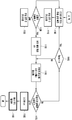
본 발명은 상기 기술한 세 가지 센싱 모드를 지원하는 장치를 가지는 기지국을 제안한다. 도 1은 3가지 센싱 모드를 지원하는 기지국 장치를 도시한 블록도이다. 도 1에 따르면, 기지국(100)은 모드 2 센싱을 제어하는 모드 2 제어부(110), 모드 1, 2 센싱을 제어하는 모드 1/2 제어부(120), 모드 3 센싱을 제어하는 모드 3 제어부(130), 모드 2 제어부(110)과 연결되어 모드 2 센싱을 위한 신호 전송을 제어하는 전송 모듈(140), 모드 1/2 제어부(120)과 모드 3 제어부(130)과 연결되어 모드 1, 2 및 3 센싱을 위한 신호 수신을 제어하는 수신 모듈(150), 모드 3 센싱을 위해 수신된 잡음 내지는 잡음 전력량 등의 정보를 수집하는 캐패시터(160), 송수신빔을 제어하는 빔 제어부(170), 신호를 생성하고 전송하고, 신호를 수신하는 안테나 모듈(180)을 포함할 수 있다. 도 1과 같이 기지국은 각 센싱 모드를 제어하기 위한 기능을 별도의 장치로 구현하거나 또는 하나의 장치를 소프트웨어를 통하여 세 가지 센싱 모드를 수행하도록 운영할 수 있다. The present invention proposes a base station having an apparatus supporting the three sensing modes described above. 1 is a block diagram illustrating a base station apparatus supporting three sensing modes. Referring to FIG. 1, the
다음으로 본 발명이 제안하는 다중 모드 시스템을 위한 피드백 모드를 기술한다Next, a feedback mode for a multi-mode system proposed by the present invention will be described.
본 발명에서 빔은 여러 단계로 구분될 수 있으며, 제안하는 방법은 총 3개의 단계로 빔을 구분하는 방법을 제안한다. 상기 3개의 단계는 일례로 아래 표 1과 같을 수 있다. 각 레벨은 빔의 크기나 형상을 의미하지 않으며 임의의 빔의 집합을 의미한다.In the present invention, the beam may be divided into several stages, and the proposed method proposes a method of dividing the beam into a total of three stages. The three steps may be as shown in Table 1 below as an example. Each level does not mean the size or shape of the beam, but means an arbitrary set of beams.
상기 표 1은 빔 집합(beam set)의 각 레벨을 기술하였으며, 이를 지시하는 방법은 다음과 같다Table 1 above describes each level of a beam set, and a method of indicating this is as follows.
- 빔 서브집합(Beam subset) 지시: CRI (CSI-RS resource index), 즉 CSI-RS 자원 인덱스를 지시하며, 빔 서브집합은 CSI-RS 자원의 집합으로 이해될 수 있다.-Beam subset indication: indicates a CSI-RS resource index (CRI), that is, a CSI-RS resource index, and the beam subset may be understood as a set of CSI-RS resources.
- 빔 그룹(Beam group) 지시: CGI (CSI-RS group index within CRI), 즉 CSI-RS 자원에 속한 CSI-RS 그룹의 그룹 인덱스를 지시하며, 빔 그룹은 CSI-RS 그룹의 집합으로 이해될 수 있다.-Beam group indication: CGI (CSI-RS group index within CRI), that is, indicates a group index of a CSI-RS group belonging to a CSI-RS resource, and a beam group is to be understood as a set of CSI-RS groups. I can.
- 빔 지시: CPI (CSI-RS antenna port index within in CGI or CRI), 즉 CSI-RS 자원 또는 CSI-RS 그룹에 속한 CSI-RS 안테나 포트의 인덱스를 지시하며, 빔은 CSI-RS 안테나 포트로 이해될 수 있다.-Beam indication: CPI (CSI-RS antenna port index within in CGI or CRI), that is, indicates the index of a CSI-RS resource or a CSI-RS antenna port belonging to a CSI-RS group, and the beam is a CSI-RS antenna port. Can be understood.
상기 CRI, CGI 및 CPI 중 적어도 하나가 상기 기술했던 채널 피드백 정보와 함께 단말로부터 기지국으로 전송될 수 있으며, 이 경우 상기 기술했던 채널 피드백 정보는 상기 CRI, CGI 및 CPI에 의해 지시된 CSI-RS 포트 또는 CSI-RS 그룹 또는 CSI-RS 자원에 해당하는 빔이 적용된 경우의 채널을 지시하는 정보로 이해될 수 있다.At least one of the CRI, CGI, and CPI may be transmitted from the terminal to the base station together with the described channel feedback information. In this case, the described channel feedback information is a CSI-RS port indicated by the CRI, CGI, and CPI. Alternatively, it may be understood as information indicating a channel when a beam corresponding to a CSI-RS group or a CSI-RS resource is applied.
기지국은 하나 이상의 빔을 하나의 빔 그룹으로 구성하여 상위 시그널링으로 단말이 지시할 수 있으며 또한, 기지국은 하나 이상의 빔 그룹을 하나의 빔 서브집합으로 구성하여 상위 시그널링으로 단말에 지시할 수 있다. 또한 기지국은 하나 이상의 빔 서브집합을 구성하여 전체 빔을 지시할 수 있다.The base station may configure one or more beams into one beam group and indicate to the terminal through higher-level signaling, and the base station may configure one or more beam groups into one beam sub-set and instruct the terminal through higher-level signaling. In addition, the base station may configure one or more beam subsets to indicate all beams.
또한, 기지국은 하나 이상의 빔을 하나의 빔 서브집합으로 구성하여 단말에 상위 시그널링으로 지시할 수 있으며, 하나 이상의 빔 서브집합을 구성하여 전체 빔을 지시할 수 있다. 여기서 빔 집합의 크기는 빔 서브집합의 크기와 같을 수 있다. In addition, the base station may configure one or more beams as one beam sub-set to instruct the UE as higher-level signaling, and may configure one or more beam sub-sets to indicate the entire beam. Here, the size of the beam set may be the same as the size of the beam subset.
또한, 기지국은 하나 이상의 빔 그룹을 하나의 빔 서브집합으로 구성하여 단말에 상위 시그널링으로 지시할 수 있으며, 여기서 빔 그룹의 크기는 1일 수 있다.In addition, the base station may configure one or more beam groups as one beam subset and indicate to the terminal as higher-level signaling, where the size of the beam group may be 1.
이러한 빔 레벨이 적용될 경우, 아래와 같은 구체적인 채널 피드백이 가능하다. When such a beam level is applied, specific channel feedback as follows is possible.
첫 번째 채널 피드백 방법은 빔의 인덱스와 RSRP 값을 피드백하는 방법이다. Cri-cpi-RSRP: 단말은 베스트 빔 내지는 보고하는 빔이 속한 빔 서브집합 인덱스(beam subset index, 이하 이는 CSI-RS 자원 인덱스로 이해 가능하다)와 해당 빔 서브집합에서의 안테나 포트 인덱스(antenna port index)를 지시하고 해당 안테나 포트에 해당하는 수신 전력(RSRP)를 피드백할 수 있다. 이 경우 피드백 정보는, CSI-RS 자원의 설정 개수를 N개라고 하고 CSI-RS 자원의 안테나 포트 수는 P, RSRP의 해상도(resolution)을 K bit이라고 하면 ![]()
![]()
Cri-RSRP: 단말은 베스트 빔 서브집합 인덱스(best beam subset index)와 해당 빔 서브집합에서의 평균적인 RSRP를 피드백할 수 있다. 이 경우 피드백 정보는, CSI-RS 자원의 설정 개수를 N개라고 하고 RSRP의 해상도를 K bit이라고 하면 ![]()
![]()
Cri-cgi-cpi-RSRP: 단말은 보고하는 빔이 속한 빔 서브집합 인덱스(beam subset index)와 해당 빔 서브집합에 해당하는 빔 그룹 인덱스(beam group index, 이는 CSI-RS 그룹 인덱스로 이해 가능하다)와 해당 빔 그룹 내의 안테나 포트 인덱스를 지시하고 해당 안테나 포트에 해당하는 수신 전력(RSRP)를 피드백할 수 있다. 이 경우 피드백 정보는, CSI-RS 자원의 설정 개수를 N개라고 하고, 각 CSI-RS 자원이 G개의 그룹으로 구성되며, 각 그룹의 CSI-RS의 안테나 포트 수는 P, RSRP의 해상도를 K bit이라고 하면 ![]()
![]()
Cri-cgi-RSRP: 단말은 베스트 빔 그룹(best beam group) 내지는 보고하는 빔이 속한 빔 서브집합 인덱스와 해당 빔 서브집합에서 빔 그룹 인덱스를 지시하고 해당 안테나 포트에서 수신된 수신 전력(RSRP)을 피드백할 수 있다. 이 경우 피드백 정보는, CSI-RS자원의 설정 개수를 N개라고 하고 CSI-RS의 그룹 수는 G, RSRP의 해상도를 K bit이라고 하면 ![]()
![]()
Cri-cgi-Ri-RSRP: 단말은 베스트 빔 그룹 내지는 보고하는 빔이 속한 빔 서브집합 인덱스와 해당 빔 서브집합에서 빔 그룹 인덱스를 지시하고 각 빔 그룹의 안테나 포트 수를 P라고 할 때, 최대 랭크가 P인 채널을 가정하고 채널 용량을 최대로 하는 랭크를 지시하고 해당 그룹에 해당하는 수신 전력(RSRP)를 피드백할 수 있다. 이 경우 피드백 정보는, CSI-RS 자원의 설정 개수를 N개라고 하고 CSI-RS의 그룹 수는 G, 그룹에 포함되는 안테나 포트의 수는 N/G 이며(즉 최대 랭크는 N/G), RSRP의 해상도를 K bit이라고 하면 ![]()
![]()
두 번째 채널 피드백 방법은 빔의 인덱스와 CQI를 피드백하는 방법이다. RSRP는 일반적으로 아래와 같은 식 14로 계산된다.The second channel feedback method is a method of feeding back the index and CQI of the beam. RSRP is generally calculated by Equation 14 below.
[식 14][Equation 14]
RSRP = PTX-PL=PRX RSRP = P TX -PL=P RX
여기서, PL은 경로 손실(pathloss)을 의미한다. RSRP는 CQI로 대체할 수 있는데 그 차이는 다음 식 15와 같다.Here, PL means pathloss. RSRP can be replaced by CQI, and the difference is shown in Equation 15 below.
[식 15][Equation 15]
CQI = f(RSRP/NP)CQI = f(RSRP/NP)
여기서 NP는 잡음 전력(noise power)인데 RSRP 대비 CQI의 장점은 NP의 값을 정확하게 기지국이 알 수 있다는 것이다. 기존의 4G 단말의 경우에는 기지국의 잡음 전력의 예측이 가능하나, 5G 시스템에서 밀리미터 웨이브를 사용하는 경우에는 단말의 구현 내지는 단말이 사용하는 대역폭에 따라 잡음 전력의 정도의 편차가 큰 편이다. 단말이 CQI를 피드백할 경우 잡음 전력의 예측을 기지국이 수행하지 않고 데이터 채널의 전송이 가능하다. 그러므로 단말은 상기 기술된 피드백 방법에서 RSRP를 CQI로 대체하여 채널 피드백을 수행할 수 있다.Here, NP is noise power, and the advantage of CQI compared to RSRP is that the base station can accurately know the value of NP. In the case of a conventional 4G terminal, it is possible to predict the noise power of a base station, but in the case of using a millimeter wave in a 5G system, the degree of noise power varies depending on the implementation of the terminal or the bandwidth used by the terminal. When the terminal feeds back the CQI, the base station can transmit the data channel without performing the prediction of the noise power. Therefore, the UE can perform channel feedback by replacing RSRP with CQI in the above-described feedback method.
이 경우 단말은 Cri-cpi-CQI, Cri-CQI, Cri-cgi-cpi-CQI, Cri-cgi-CQI, Cri-cgi-Ri-CQI 의 피드백이 가능하다.In this case, the UE can provide feedback of Cri-cpi-CQI, Cri-CQI, Cri-cgi-cpi-CQI, Cri-cgi-CQI, and Cri-cgi-Ri-CQI.
세 번째 피드백 방법은 빔 인덱스만을 피드백하는 것이다. 앞서 기술한 바와 같이 기지국이 센싱 모드 2로 채널 정보 내지는 반사 계수를 추정하면 이 후에는 단말의 RSRP에 대한 피드백이 필요하지 않으며, 따라서 빔이 변경되지 않는 고정형 단말의 경우 피드백 없이 기지국의 스케줄링이 가능할 수 있다. 만약 기지국이 단말의 이동성을 고려하여 지속적인 단말의 트래킹 이 필요한 경우에는 RSRP나 CQI 없이 빔 인덱스 내지는 빔 그룹 인덱스 또는 빔 서브집합 인덱스를 피드백한다.The third feedback method is to feed back only the beam index. As described above, if the base station estimates the channel information or the reflection coefficient in sensing mode 2, there is no need for feedback on the RSRP of the terminal after that, so in the case of a fixed terminal in which the beam is not changed, scheduling of the base station is possible without feedback. I can. If the base station needs continuous tracking of the terminal in consideration of the mobility of the terminal, it feeds back a beam index, a beam group index, or a beam subset index without RSRP or CQI.
이 경우 단말은 Cri-cpi, Cri-cgi-cpi, Cri-cgi 의 피드백이 가능하다.In this case, the UE can provide feedback of Cri-cpi, Cri-cgi-cpi, and Cri-cgi.
다음으로 본 발명이 제안하는 다중 모드 장치를 위한 새로운 피드백 구성 요소를 기술한다. Next, a new feedback component for a multi-mode device proposed by the present invention will be described.
TPS (transmit panel selection)는 다음과 같다. 수신기는 센싱을 통해 사용 가능한 패널(panel, 또는 안테나 패널(antenna panel), 이는 안테나로 이해될 수 있다)의 개수 내지는 구성에 대해서 송신기로 피드백할 수 있다. 이동형 수신기(일례로 단말)의 경우에는 주변 사물의 위치 내지는 사용자의 손이나 몸에 의해서 일부 패널에 의한 신호 수신이 불가능한 경우가 발생한다. 이러한 사건을 송신기와 수신기 사이의 피드백에 의지하여 기지국이 파악할 경우 사건 발생과 기지국의 파악 사이의 시간 지연이 발생하게 된다. 하지만 단말은 센싱을 통해서 자신의 일부 패널이 순시적으로 통신 불능의 상태에 있다는 사실을 파악할 수 있다. TPS (transmit panel selection) is as follows. The receiver may feedback the number or configuration of the available panels (or antenna panels, which can be understood as antennas) to the transmitter through sensing. In the case of a mobile receiver (for example, a terminal), it may be impossible to receive signals by some panels due to the location of nearby objects or the user's hand or body. When the base station recognizes such an event based on the feedback between the transmitter and the receiver, there is a time delay between the occurrence of the event and the detection of the base station. However, the terminal can grasp the fact that some of its panels are in a state of instantaneous communication failure through sensing.
일례로 단말은 센싱 모드 2 센싱을 통해서 자신이 전송한 신호의 반사파를 수신하여 주변 반사체와의 거리가 매우 가까운 경우에 상기 신호를 전송했던 패널을 통신 불능 상태로 판단할 수 있다. 가령 단말이 4개의 패널을 가지고 있는 경우 상기 4개의 패널을 통해서 mode 2 센싱을 수행하고 그 중에 2개의 패널이 사용 불가한 경우, 단말은 기지국과 공유하는 미리 구성된 랭크 4 코드북 중에서 랭크 1 내지는 2에 따른 코드북 중 적절한 인덱스를 PMI로 선택하며, 사용될 RS의 안테나 포트 인덱스 2개를 선택하는 피드백을 기지국으로 전송할 수 있다.For example, when the terminal receives the reflected wave of the signal transmitted by itself through sensing mode 2 sensing and the distance to the surrounding reflector is very close, the terminal may determine that the panel that transmitted the signal is in a communication disabled state. For example, if the terminal has four panels, mode 2 sensing is performed through the four panels, and if two panels are not available, the terminal is assigned to
TPF (transmit panel format)은 폴딩(folding) 단말로 인해서 단말의 안테나 구조가 변경되는 것을 지시하기 위한 피드백 구성 요소이다. 상기 폴딩 단말(또는 폴더블(fordable) 단말)은 일례로 부착되어있는 디스플레이를 곡절 가능한 단말 장치로, 두 부분(이하 폴드면)으로 나뉘어 한 번 폴딩되며 디스플레이는 폴딩 내측에 부착될 수 있다. 이 경우 상기 두 부분에 각각 안테나 패널이 배치될 수 있다. 도 2는 폴딩 단말의 폴딩 여부에 따른 안테나 패널의 변화의 일례를 도시한 도면이다. 폴딩 상태(A, 200)에서는 단말의 각 폴드면에 배치된 안테나 패널이 서로 겹쳐지게 되므로 이는 코-로케이티드(co-located)된 X-pol 안테나로 보이게 되고, 언폴딩(un-folding) 상태에서는 단말의 각 폴드면에 배치된 안테나 패널이 서로 분리되므로 각 안테나 패널이 상당한 거리를 가지고 있는 것으로 보이게 된다. 이와 같이 폴딩 및 언폴딩 여부에 따라 안테나 구조가 변경되게 되고, 각 안테나 간의 채널을 합친 채널 행렬 H에서 안테나 간의 채널간 코릴레이션(correlation)이 떨어지기 때문에 채널 간의 정보 단절을 해결하기 위해 폴딩 단말의 폴딩 여부에 대한 지시자가 필요하다. 일례로, TPF를 1bit으로 지시하는 것은 아래 표 2, TPF를 2 bit으로 지시하는 경우 표 3를 참고할 수 있다.TPF (transmit panel format) is a feedback component for indicating that the antenna structure of the terminal is changed due to the folding terminal. The folding terminal (or foldable terminal) is, for example, a terminal device that can bend an attached display, and is divided into two parts (hereinafter, a fold surface) and folded once, and the display may be attached to the inside of the folding. In this case, an antenna panel may be disposed at each of the two portions. 2 is a diagram illustrating an example of a change in an antenna panel according to whether a folding terminal is folded. In the folded state (A, 200), since the antenna panels disposed on each fold surface of the terminal overlap each other, it appears as a co-located X-pol antenna, and is in an unfolding state. In, since the antenna panels disposed on each fold surface of the terminal are separated from each other, it appears that each antenna panel has a considerable distance. In this way, the antenna structure is changed depending on whether or not the channels are folded or unfolded, and the correlation between the channels between the antennas in the channel matrix H that is the sum of the channels between the antennas decreases. An indicator of whether or not to be folded is required. For example, for indicating TPF as 1 bit, see Table 2 below, and for indicating TPF as 2 bits, see Table 3.
표 2는 폴딩 단말을 위한 것으로 각 폴드면에 하나의 안테나 패널이 각각 존재하며 각 안테나 패널이 폴딩 상태에서 서로 다른 편파(polarization)를 지원하도록 구성하는 장치를 위한 것이다. 따라서, TPF 0으로 지시되는 폴딩 상태에서는 기지국은 단말의 안테나를 코-로케이티드된 X-pol 안테나 형상으로 파악하고, TPF 1의 언폴딩 상태에서는 상당한 거리를 가지고 있는 서로 다른 두 개의 안테나의 형상으로 파악할 수 있다. 따라서, 기지국은 단말의 TPF에 따라서 가장 적합한 빔을 선택적으로 사용할 수 있다. 일반적으로 바람직하게는 TPF가 0인 경우에는 하나의 기지국에서 랭크 2를 이용해 동일한 빔 방향을 사용해 X-pol 안테나로 신호를 전송하는 방법이 사용될 수 있고, TRF가 1인 경우에는 하나 이상의 기지국에서 각 기지국은 랭크 1의 빔을 사용하여 동시에 신호를 송수신하거나, 둘 중에 하나의 안테나만 신호 송수신에 사용하는 안테나 선택(antenna selection)이 사용될 수 있다.Table 2 is for a folding terminal, and is for a device in which one antenna panel exists on each fold surface, and each antenna panel supports different polarizations in a folded state. Therefore, in the folding state indicated by TPF 0, the base station recognizes the antenna of the terminal as a co-located X-pol antenna shape, and in the unfolding state of
표 3은 폴딩 단말을 위한 것으로 각 폴드면에 하나의 안테나 패널이 각각 존재하며, 각 안테나 패널이 폴딩 상태에서 안테나 재설정(antenna reconfiguration,, 즉 패널 간의 간격 변화 및 활성화된 안테나 패널의 수가 변하는 것을 의미한다)과 편파(polarization)의 변화를 지원하도록 구성하는 장치를 위한 것이다. TPF가 00인 것은 단말이 폴딩된 상태에서 하나의 안테나 패널은 +45도 내지는 +90도의 편파인 상태를 의미하며 이 경우 하나의 기지국과의 최대 랭크가 2인 단일 빔(즉 동일한 빔 방향)이 신호 송수신에 사용될 수 있다. TPF가 01인 것은 언폴딩 상태의 단말이 서로 같은 편파로 각 안테나 패널이 적어도 10λ 이상의 거리를 가지게 된 상태를 의미한다(λ는 파장의 거리에 해당한다). 이 경우 2개의 기지국과 랭크 1의 빔을 사용해 동시에 신호를 송수신하거나 또는 둘 중 하나의 안테나만 신호 송수신에 사용될 수 있다. TPF가 10인 것은 폴딩된 단말이 서로 같은 편파로 두 개의 안테나 패널이 중첩되어 있는 상태를 의미한다. 이 경우 랭크 1의 단일 빔을 이용한 신호 송수신이 가능하다. TPF가 11인 것은 단말이 언폴딩된 상태로 수 개의 안테나 패널의 거리가 2λ이하의 거리를 가지고 있는 경우를 의미한다. 이 경우 랭크 2의 단일 빔을 이용한 신호 송수신이 가능하다. Table 3 is for a folding terminal, meaning that one antenna panel exists on each fold surface, and antenna reconfiguration (i.e., a change in the spacing between panels and the number of activated antenna panels) in each antenna panel is in a folding state. It is intended for a device that is configured to support changes in polarization and polarization. When the TPF is 00, one antenna panel has a polarization of +45 degrees to +90 degrees in a state in which the terminal is folded, and in this case, a single beam with a maximum rank of 2 with one base station (that is, the same beam direction) is It can be used for signal transmission and reception. A TPF of 01 means a state in which the UEs in the unfolded state have the same polarization and each antenna panel has a distance of at least 10λ (λ corresponds to the distance of the wavelength). In this case, two base stations and a
또한 상기 TPS 또는/및 TPF가 채널 피드백 정보에 포함되어 단말에 의해 기지국으로 피드백되는 경우, 기지국은 채널 피드백 정보의 컴포넌트를 상기 TPS 또는 TPF에 기반해 확인할 수 있다. 일례로 TPF가 2비트인 경우 TPF의 값이 10이라면 랭크 1의 단일 빔을 생성하도록 하는 하나 이상의 프리코더(precoder, 이는 프리코딩 행렬(precoding matrix)로 이해될 수 있다)를 포함하는 코드북이 단말과 기지국 사이에 가정될 수 있고, 채널 피드백 정보에 포함된 PMI는 상기 코드북의 프리코더의 인덱스를 지시하는 것으로 이해될 수 있고, 채널 피드백 정보에 포함된 CQI는 상기 지시된 채널 행렬이 적용된 전송의 경우의 채널 용량을 지시하는 것으로 이해될 수 있다. 또한 기지국과 단말은 상기 TPS 또는/및 TPF에 의해 파악된 가능한 랭크와 빔의 수를 기반으로 데이터 송수신을 수행할 수 있다. 일례로 기지국은 상기 TPS 또는/및 TPF에 의해 파악된 코드북의 프리코더를 적용해 데이터를 전송할 수 있으나, 본 발명은 이러한 일례에 제한되지 않는다.In addition, when the TPS or/and TPF is included in the channel feedback information and is fed back to the base station by the terminal, the base station may check a component of the channel feedback information based on the TPS or TPF. For example, if the TPF is 2 bits and the TPF value is 10, a codebook including at least one precoder (which can be understood as a precoding matrix) to generate a single beam of
아래에서는 랭크 모드(rank mode)를 지시하는 방법에 대해 기술한다. 랭크 모드는 플레인 모드(plane mode) 또는 스파이럴 모드(spiral mode)의 적용을 지시하는 지시자이다. 본 발명에서 제안하는 방법은 송신기와 수신기 간의 랭크 모드를 지시하기 위한 방법으로, 수신기가 송신기에 접속하면서 자신의 랭크 모드를 선택하거나 변경하기 위한 피드백이다. 여기서 랭크 모드라는 것은 랭크를 구성하는 채널 모드를 의미하고 플레인 모드와 스파이럴 모드가 있다. 플레인 모드는 송신기와 수신기가 평면파(plane wave)를 전송하여 발생하는 랭크를 이용하는 모드를 의미한다. 평면파는 일반적으로 등간격 배열 안테나(uniform array antenna)를 통해서 발생이 가능하며, 어레이들(arrays)로 구성된 안테나 요소(antenna element)가 임의의 방향성을 가지는 위상 차이를 가지는 신호를 3차원 직교 좌표의 특정 방향으로 전송하는 방법을 의미한다. 이론적으로는 안테나에 있는 RF(radio frequency)의 개수만큼 최대 랭크을 얻을 수 있으며 안테나 요소가 많더라도 RF 경로(RF path)가 1개인 경우에는 랭크가 1인 것이 특징이다. 반면, 스파이럴 모드는 송신기와 수신기가 나선형 파(spiral wave)를 전송하여 발생하는 랭크를 이용하는 모드를 의미한다. 나선형 파는 일반적으로 순환 배열 안테나(circular array antenna) 를 통해서 발생이 가능하다. 원형으로 배치된 어레이들이 특정 시간 차이를 가지고 위상이 로테이션(rotation)하는 형상으로 신호가 전송되며, 3차원의 각 좌표의 위상 차이를 통해서 랭크가 얻어질 수 있으며 안테나 요소와 무관하게 RF 경로와 분해 가능한 위상 차이를 통해서 랭크가 발생하는 것이 특징이다. Hereinafter, a method of indicating a rank mode will be described. The rank mode is an indicator indicating application of a plane mode or a spiral mode. The method proposed in the present invention is a method for indicating a rank mode between a transmitter and a receiver, and is feedback for selecting or changing its own rank mode while the receiver accesses the transmitter. Here, the rank mode means a channel mode constituting a rank, and there are a plane mode and a spiral mode. The plane mode refers to a mode using a rank generated by transmitting a plane wave between a transmitter and a receiver. The plane wave can be generated through a uniform array antenna in general, and a signal having a phase difference in which an antenna element composed of arrays has an arbitrary directionality is transmitted in 3D orthogonal coordinates. It refers to a method of transmitting in a specific direction. Theoretically, the maximum rank can be obtained as much as the number of radio frequencies (RF) in the antenna, and even if there are many antenna elements, the rank is 1 when there is only one RF path. On the other hand, the spiral mode refers to a mode using a rank generated by transmitting a spiral wave between a transmitter and a receiver. Spiral waves can generally be generated through a circular array antenna. Signals are transmitted in a shape in which the phase of the arrays arranged in a circle rotate with a specific time difference, and the rank can be obtained through the phase difference of each coordinate in three dimensions, and the RF path and decomposition are independent of the antenna element. It is characterized by the occurrence of rank through possible phase difference.
플레인 모드는 일반적으로 반사파가 많은 환경에 적합하고 스파이럴 모드는 일반적으로 LOS(line-of-sight) 환경에 적합하다. LOS 환경의 경우에는 플레인 모드로 운영하면 RF 경로에 무관하게 랭크가 증가하지 못하게 되는 경향이 있다. 따라서 채널 용량을 늘리기 위해 LOS 환경에서는 랭크 모드를 스파이럴 모드로 변경하는 것이 좋다. 또한, 스파이럴 모드의 경우에는 송신기와 수신기의 거리가 멀어질수록 수신기의 위상 차이를 해석하는 능력이 떨어지기 때문에 플레인 모드 대비 전송 거리가 줄어드는데, LOS 채널의 경우에는 신호의 수신 전력의 크기가 세기 때문에 스파이럴 모드가 유리할 수 있다. The plane mode is generally suitable for environments with a lot of reflected waves, and the spiral mode is generally suitable for a line-of-sight (LOS) environment. In the case of the LOS environment, when operating in the plane mode, there is a tendency that the rank cannot be increased regardless of the RF path. Therefore, in order to increase the channel capacity, it is recommended to change the rank mode to the spiral mode in the LOS environment. In addition, in the case of the spiral mode, as the distance between the transmitter and the receiver increases, the ability to interpret the phase difference of the receiver decreases, so the transmission distance decreases compared to the plane mode.In the case of the LOS channel, the amount of received power of the signal increases. Therefore, the spiral mode can be advantageous.
따라서 본 발명에서 제안하는 방법은 단말이 채널 상태에 따라 플레인 모드와 스파이럴 모드를 변경하는 1 bit 피드백 내지는 수신기가 플레인 모드와 스파이럴 모드로 운영이 가능한지에 대한 단말 능력(UE capability) 시그널링을 송신기에 전달하는 방법을 포함한다. 또한 본 발명에서는 송신기는 수신기가 피드백한 랭크 모드에 따라서 서로 다른 코드북을 구성할 수 있으며 또는 송신기는 수신기의 능력에 따라서 플레인 모드를 위한 코드북 내지는 스파이럴 모드를 위한 코드북 내지는 두 개의 랭크 모드를 혼합하여 운영하기 위한 코드북을 구성하고 수신기에 이를 지시하는 시그널링을 전송할 수 있다. Therefore, the method proposed in the present invention delivers 1-bit feedback in which the terminal changes the plane mode and the spiral mode according to the channel state, or the UE capability signaling on whether the receiver can operate in the plane mode and the spiral mode to the transmitter. Includes how to do it. In addition, in the present invention, the transmitter may configure different codebooks according to the rank mode fed back by the receiver, or the transmitter operates a codebook for a plane mode or a codebook for a spiral mode or a combination of two rank modes according to the capabilities of the receiver. It is possible to configure a codebook for the purpose and transmit signaling indicating this to the receiver.
다음으로 본 발명이 제안하는 다중 모드 시스템을 위한 송신기의 모드를 기술한다. 제안하는 방법의 송신기와 수신기는 기존의 활성화 모드(Active mode 또는 연결 모드(connected mode)), 유휴 모드(Idle mode)와 별도로 다음 기술되는 모드로 천이할 수 있다. 기존의 활성화 모드는 송신기와 수신기 간의 통신이 가능한 모드를 의미하며 유휴 모드는 송신기가 더 이상 전송할 데이터가 없는 경우 수신기의 전원이 꺼진 것은 아니지만 더 이상 통신을 지원하지 않는 상태를 의미한다. 유휴 모드에서는 수신기는 특정 시간에 잠시 활성 모드로 전환하여 자신이 수신할 데이터가 있는지를 확인하고, 수신할 데이터가 없는 경우 다시 유휴 모드로 모드를 전환한다. Next, the mode of the transmitter for the multi-mode system proposed by the present invention will be described. The transmitter and receiver of the proposed method may transition to a mode described below separately from the existing active mode (active mode or connected mode) and idle mode. The existing activation mode refers to a mode in which communication between the transmitter and the receiver is possible, and the idle mode refers to a state in which the power of the receiver is not turned off when there is no more data to be transmitted by the transmitter, but communication is no longer supported. In the idle mode, the receiver temporarily switches to the active mode at a specific time to check whether there is data to be received, and when there is no data to be received, the receiver switches the mode back to the idle mode.
반면, 본 발명에서 제안하는 방법에 따르면 송신기 및/또는 수신기는 아래와 같은 네 가지 모드를 가질 수 있다. 다음은 각 모드를 설명한 것이다.On the other hand, according to the method proposed in the present invention, the transmitter and/or the receiver may have the following four modes. The following describes each mode.
1. 활성화 모드(Active mode) (모든 모드를 운영 가능한 모드): 활성화 모드는 송신기 내지는 수신기가 통신 모드와 센싱 모드를 모두 운영하는 경우를 의미한다. 송신기와 수신기는 센싱 모드를 운영하는 경우 센싱 모드에 유입되는 통신 신호에 의한 간섭을 방지하거나 통신 신호와 간섭이 발생하는 경우에 신호 제거 회로를 동작시키기 위해 서로 활성화 모드임을 인지해야 할 필요성이 있다. 센싱 모드가 운영되는 상태에서 통신 모드가 함께 운영될 경우 통신 신호의 전력이 너무 높기 때문에 센싱을 위한 신호가 검출되기 어렵기 때문이다. 1. Active mode (mode capable of operating all modes): The active mode refers to a case in which the transmitter or the receiver operates both a communication mode and a sensing mode. When operating the sensing mode, the transmitter and the receiver need to recognize that they are mutually active modes to prevent interference by a communication signal flowing into the sensing mode or to operate a signal canceling circuit when interference with the communication signal occurs. This is because, when the communication mode is operated together while the sensing mode is operated, the power of the communication signal is too high, so that it is difficult to detect a signal for sensing.
2. 준 활성화 모드(Semi-active mode) (액티브 센싱만 가능한 모드): 준 활성화 모드는 송신기 또는 수신기가 통신 모드는 수행하지 않고 액티브 센싱 모드만 수행하는 상태를 의미한다. 이 때, 송신기와 수신기는 데이터 송수신 없이 액티브 센싱 내지는 패시브 센싱이 가능하고, 이러한 준 활성화 모드로 상위 시그널링으로 미리 설정된 시간과 주기에 따라 수행되거나 수신기 또는 송신기가 임의로 지시하거나 명령하여 진입할 수 있다.2. Semi-active mode (mode in which only active sensing is possible): Semi-active mode means a state in which the transmitter or receiver performs only the active sensing mode without performing the communication mode. In this case, the transmitter and the receiver can perform active sensing or passive sensing without transmitting and receiving data, and in this quasi-activation mode, higher-level signaling is performed according to a preset time and period, or may be arbitrarily indicated or commanded by the receiver or transmitter to enter.
3. 유휴 모드(Idle mode)(아무것도 수행되지 않음): 유휴 모드는 기존과 동일하게 통신과 센싱을 모두 진행하지 않는 상태를 의미한다.3. Idle mode (nothing is done): Idle mode means a state in which both communication and sensing are not performed as before.
4. 패시브 모드(Passive mode) (또는 이는 부분적 유휴 모드로 칭해질 수 있으며, 신호의 수신만 가능한 상태이다): 패시브 모드는 수신 회로만 동작하는 상태를 의미한다. 본 발명은 수신기 내지는 송신기가 자신이 패시브 모드인 상태인지 인지하도록 상대방에게 시그널링을 전송하는 방법을 포함한다. 4. Passive mode (or this may be referred to as a partial idle mode, and only signal reception is possible): Passive mode refers to a state in which only the receiving circuit is operated. The present invention includes a method of transmitting signaling to a counterpart so that a receiver or a transmitter recognizes whether it is in a passive mode.
다음으로 본 발명이 제안하는 다중 모드 시스템을 위한 수신기의 모드를 기술한 것이다. 그러나 이러한 모드가 송신기에 적용되는 것을 배제하지 않는다.Next, the mode of the receiver for the multi-mode system proposed by the present invention is described. However, it does not preclude that this mode is applied to the transmitter.
1. 통신 모드(Communication mode): 통신 모드는 모든 안테나 패널이 통신을 위해 사용되는 경우를 의미한다. 1. Communication mode: Communication mode refers to a case where all antenna panels are used for communication.
2. 듀얼 모드(Dual mode): 듀얼 모드는 일부의 안테나 패널은 통신을 위해 사용되고, 남은 안테나 패널이 다른 용도로 사용되는 모드이다. 수신기는 재구성 내지는 변경 가능한(re-configurable) 안테나를 포함하는지 여부 및 다중 모드의 프리코더를 설정할 수 있는지 여부를 단말 능력 시그널링으로 송신기로 보고할 수 있으며, 수신기는 재설정된 설정을 송신기로 전송할 수 있다.2. Dual mode: In the dual mode, some antenna panels are used for communication and the remaining antenna panels are used for other purposes. The receiver can report to the transmitter whether it includes a reconfigurable or re-configurable antenna and whether a multimode precoder can be set, through terminal capability signaling, and the receiver can transmit the reset configuration to the transmitter. .
3. 유휴 모드(Idle mode): 유휴 모드는 모든 안테나 패널이 통신 이외의 용도를 위해 사용되는 모드로, 송신기가 설정한 블랭크 심볼에서 센싱된 채널 또는 측정 결과를 송신기로 보고하거나 또는 채널 파악을 위해 사용할 수 있다. 또한 수신기는 유휴 모드 및 블랭크 심볼에서의 센싱이 가능한지 여부에 대한 정보를 포함하는 단말 능력 시그널링을 송신기로 보고할 수 있다. 3. Idle mode: Idle mode is a mode in which all antenna panels are used for purposes other than communication, and to report the channel or measurement result sensed from the blank symbol set by the transmitter to the transmitter or to identify the channel. Can be used. In addition, the receiver may report terminal capability signaling including information on whether sensing in the idle mode and blank symbol is possible to the transmitter.
도 3은 상기 기술한 다중 모드 시스템의 송신기의 채널 피드백 방법을 도시한 도면이다. 3 is a diagram illustrating a channel feedback method of a transmitter in the multi-mode system described above.
도 3에 따르면, 도시되지 않았으나 선택적으로 송신기(이는 기지국으로 이해될 수 있다)는 수신기(이는 단말로 이해될 수 있다)로 단말 능력 시그널링을 수신할 수 있다. 상기 단말 능력 시그널링에는 본 발명에서 제안하는 새로운 피드백 구성 요소의 지원 여부, 새로운 모드의 지원 여부 등 본 발명에서 제안하는 기능 중 적어도 하나를 수신기가 지원할 수 있는지 여부를 지시하는 정보가 포함될 수 있다.According to FIG. 3, although not shown, optionally, a transmitter (which may be understood as a base station) may receive terminal capability signaling through a receiver (which may be understood as a terminal). The terminal capability signaling may include information indicating whether the receiver can support at least one of the functions proposed in the present invention, such as whether a new feedback component proposed in the present invention is supported or whether a new mode is supported.
송신기는 채널 피드백 설정 정보 및/또는 CSI-RS 설정 정보를 수신기로 전송한다(300). 상기 채널 피드백 설정 정보는 수신기가 피드백해야 하는 채널 피드백 정보의 종류, 채널 피드백의 시간 설정 정보(이는 주기적 채널 피드백 또는 비주기적 채널 피드백 등을 포함할 수 있고, 주기적 채널 피드백의 경우 피드백의 주기 및 오프셋이 포함될 수 있다), 채널 피드백을 위한 자원(일례로 복수의 CSI-RS 자원이 설정된 경우 채널 피드백의 대상이 되는 CSI-RS 자원), 채널 피드백에 적용되어야 하는 코드북 정보 등 중 적어도 하나가 포함될 수 있다. 또한 CSI-RS 설정 정보에는 CSI-RS 자원 및/또는 CSI-RS 그룹 및/또는 CSI-RS 안테나 포트를 설정하는 정보가 포함될 수 있으며, 각 CSI-RS 안테나 포트에 해당하는 시간 및 주파수 자원 정보, CSI-RS 시퀀스 정보 등 중 적어도 하나가 포함될 수 있다. 또한 상기 설정 정보와 별개로 송신기는 수신기에게 SRS 설정 정보 및 블랭크 심볼 설정 정보를 전송할 수 있다.The transmitter transmits channel feedback configuration information and/or CSI-RS configuration information to the receiver (300). The channel feedback setting information may include the type of channel feedback information to be fed back by the receiver, and time setting information of the channel feedback (this may include periodic channel feedback or aperiodic channel feedback, and in the case of periodic channel feedback, the period and offset of the feedback. May be included), a resource for channel feedback (for example, a CSI-RS resource that is a target of channel feedback when a plurality of CSI-RS resources are configured), at least one of codebook information to be applied to the channel feedback, etc. may be included. have. In addition, the CSI-RS configuration information may include information for configuring a CSI-RS resource and/or a CSI-RS group and/or a CSI-RS antenna port, and time and frequency resource information corresponding to each CSI-RS antenna port, At least one of CSI-RS sequence information and the like may be included. In addition, separately from the configuration information, the transmitter may transmit SRS configuration information and blank symbol configuration information to the receiver.
이후 송신기는 수신기로 설정된 CSI-RS를 전송하고(310), 수신기가 전송하는 채널 피드백 정보를 수신한다(300), 상기 채널 피드백 정보는 상기 기술했던 RI, PMI, CQI 및 CRI 뿐만 아니라 빔을 지시하기 위한 CGI, CPI 중 적어도 하나와 RSRP가 포함될 수 있으며, TPS 또는/및 TPF 또는/및 랭크 모드를 지시하는 지시자가 포함될 수도 있다. TPS 또는/및 TPF 또는/및 랭크 모드를 지시하는 지시자가 채널 피드백 정보에 포함될 경우, 송신기는 수신기가 사용하는 코드북을 TPS 또는/및 TPF 또는/및 랭크 모드를 지시하는 지시자에 기반해 파악할 수 있다. 일례로 TPF가 1비트인 경우 TPF의 값이 0일 경우 송신기는 수신기가 최대 랭크 2의 동일한 빔 방향을 사용하는 코드북을 가정하고 채널 피드백 정보를 생성했을 것으로 파악하고 상기 코드북을 기반으로 수신기가 피드백한 채널을 확인한 후 확인된 채널을 기반으로 데이터 송수신을 위한 스케줄링을 수행할 수 있다. 또한 상기 본 발명에서 새롭게 제안한 채널 피드백 구성 요소는 종래의 채널 피드백 정보와 함께 피드백되는 것도 가능하나, 수신기에 의해 별개로 피드백되는 것도 가능하다.Thereafter, the transmitter transmits the CSI-RS set to the receiver (310), and receives the channel feedback information transmitted by the receiver (300), and the channel feedback information indicates the beam as well as the RI, PMI, CQI and CRI described above. At least one of CGI and CPI and RSRP for CGI and CPI may be included, and an indicator indicating TPS or/and TPF or/and rank mode may be included. When an indicator indicating TPS or/and TPF or/and rank mode is included in the channel feedback information, the transmitter may determine the codebook used by the receiver based on the TPS or/and TPF or/and an indicator indicating the rank mode. . For example, if the TPF is 1 bit and the TPF value is 0, the transmitter assumes that the receiver has generated the channel feedback information assuming a codebook using the same beam direction of the maximum rank 2, and the receiver provides feedback based on the codebook. After checking one channel, scheduling for data transmission and reception can be performed based on the confirmed channel. In addition, the channel feedback component newly proposed in the present invention may be fed back together with conventional channel feedback information, but may be fed back separately by a receiver.
도 4는 상기 기술한 다중 모드 시스템의 수신기의 채널 피드백 방법을 도시한 도면이다.4 is a diagram illustrating a channel feedback method of a receiver in the multi-mode system described above.
도 4에 따르면, 도시되지 않았으나 선택적으로 수신기(이는 단말로 이해될 수 있다)는 송신기(이는 기지국으로 이해될 수 있다)로 단말 능력 시그널링을 전송할 수 있다. 상기 단말 능력 시그널링에는 본 발명에서 제안하는 새로운 피드백 구성 요소의 지원 여부, 새로운 모드의 지원 여부 등 본 발명에서 제안하는 기능 중 적어도 하나를 수신기가 지원할 수 있는지 여부를 지시하는 정보가 포함될 수 있다.According to FIG. 4, although not shown, optionally, a receiver (which may be understood as a terminal) may transmit terminal capability signaling to a transmitter (which may be understood as a base station). The terminal capability signaling may include information indicating whether the receiver can support at least one of the functions proposed in the present invention, such as whether a new feedback component proposed in the present invention is supported or whether a new mode is supported.
수신기는 송신기로부터 채널 피드백 설정 정보 및/또는 CSI-RS 설정 정보를 수신한다(400). 상기 채널 피드백 설정 정보는 수신기가 피드백해야 하는 채널 피드백 정보의 종류, 채널 피드백의 시간 설정 정보(이는 주기적 채널 피드백 또는 비주기적 채널 피드백 등을 포함할 수 있고, 주기적 채널 피드백의 경우 피드백의 주기 및 오프셋이 포함될 수 있다), 채널 피드백을 위한 자원(일례로 복수의 CSI-RS 자원이 설정된 경우 채널 피드백의 대상이 되는(즉 수신기가 측정하여야 할) CSI-RS 자원), 채널 피드백에 적용되어야 하는 코드북 정보 등 중 적어도 하나가 포함될 수 있다. 또한 CSI-RS 설정 정보에는 CSI-RS 자원 및/또는 CSI-RS 그룹 및/또는 CSI-RS 안테나 포트를 설정하는 정보가 포함될 수 있으며, 각 CSI-RS 안테나 포트에 해당하는 시간 및 주파수 자원 정보, CSI-RS 시퀀스 정보 등 중 적어도 하나가 포함될 수 있다. 또한 상기 설정 정보와 별개로 수신기는 송신기로부터 SRS 설정 정보 및 블랭크 심볼 설정 정보를 수신할 수 있다.The receiver receives channel feedback configuration information and/or CSI-RS configuration information from the transmitter (400). The channel feedback setting information may include the type of channel feedback information to be fed back by the receiver, and time setting information of the channel feedback (this may include periodic channel feedback or aperiodic channel feedback, and in the case of periodic channel feedback, the period and offset of the feedback. May be included), a resource for channel feedback (for example, a CSI-RS resource that is a target of channel feedback (that is, a receiver should measure) when a plurality of CSI-RS resources are configured), a codebook to be applied to the channel feedback At least one of information and the like may be included. In addition, the CSI-RS configuration information may include information for configuring a CSI-RS resource and/or a CSI-RS group and/or a CSI-RS antenna port, and time and frequency resource information corresponding to each CSI-RS antenna port, At least one of CSI-RS sequence information and the like may be included. In addition, apart from the configuration information, the receiver may receive SRS configuration information and blank symbol configuration information from the transmitter.
이후 수신기는 송신기로부터 CSI-RS 설정 정보를 기반으로 CSI-RS를 수신하고(410), 수신기는 채널 피드백 설정 정보 및 상기 CSI-RS 수신 결과 및 수신기의 센싱 결과를 기반으로 채널 피드백 정보를 생성한다(420). 상기 채널 피드백 정보는 상기 기술했던 RI, PMI, CQI 및 CRI 뿐만 아니라 빔을 지시하기 위한 CGI, CPI 중 적어도 하나와 RSRP가 포함될 수 있으며, TPS 또는/및 TPF 또는/및 랭크 모드를 지시하는 지시자가 포함될 수도 있다. 수신기는 본 발명에서 기술된 센싱 모드에 따른 방법을 통해 또는/및 폴딩 여부/또는 안테나 형상의 변경 여부의 센싱을 통해 TPS 또는/및 TPF를 생성할 수 있다. 또한 측정된 채널을 통해 랭크 모드를 결정할 수 있다. Thereafter, the receiver receives the CSI-RS from the transmitter based on the CSI-RS configuration information (410), and the receiver generates channel feedback information based on the channel feedback configuration information and the CSI-RS reception result and the sensing result of the receiver. (420). The channel feedback information may include at least one of CGI, CPI and RSRP for indicating a beam, as well as RI, PMI, CQI and CRI described above, and an indicator indicating TPS or/and TPF or/and rank mode is It may be included. The receiver may generate the TPS or/and TPF through the method according to the sensing mode described in the present invention or/and sensing whether to fold or change the shape of the antenna. In addition, the rank mode can be determined through the measured channel.
상기와 같이 TPS 또는/및 TRP 또는/및 랭크 모드를 지시하는 지시자가 채널 피드백 정보에 포함된 경우, 수신기는 채널 피드백을 생성하기 위해 사용하는 코드북을 상기 센싱 결과 및 TPS 또는/및 TPF 또는/및 랭크 모드를 지시하는 지시자에 기반해 결정할 수 있다. 일례로 TPF가 1비트인 경우 TPF의 값이 0일 경우 수신기는 최대 랭크 2의 동일한 빔 방향을 사용하는 코드북을 가정하고 채널 피드백 정보를 생성한다. 이후 수신기는 생성한 채널 피드백 정보를 채널 피드백 설정 정보를 기반으로 송신기로 전송한다(430). 이후 송신기는 채널 피드백 정보를 기반으로 파악된 채널을 기반으로 데이터 송수신을 위한 스케줄링을 수행할 수 있다. 또한 상기 본 발명에서 새롭게 제안한 채널 피드백 구성 요소는 종래의 채널 피드백 정보와 함께 피드백되는 것도 가능하나, 수신기에 의해 별개로 피드백되는 것도 가능하다.When the indicator indicating the TPS or/and TRP or/and rank mode as described above is included in the channel feedback information, the receiver determines the sensing result and the TPS or/and TPF or/and the codebook used to generate the channel feedback. It can be determined based on an indicator indicating the rank mode. For example, when the TPF is 1 bit and the TPF value is 0, the receiver assumes a codebook using the same beam direction of the maximum rank 2 and generates channel feedback information. Thereafter, the receiver transmits the generated channel feedback information to the transmitter based on the channel feedback configuration information (430). Thereafter, the transmitter may perform scheduling for data transmission/reception based on a channel determined based on the channel feedback information. In addition, the channel feedback component newly proposed in the present invention may be fed back together with conventional channel feedback information, but may be fed back separately by a receiver.
도 5는 본 발명의 다중 모드 송수신기가 포함하는 모듈의 구조를 도시한 블록도이다.5 is a block diagram showing the structure of a module included in the multi-mode transceiver of the present invention.
도 5에 따르면, 다중 모드의 송수신기는 통신 신호 발생기(512), 센싱 신호 발생기(514)를 포함하는 신호 발생기(510), 선택기(520), 통신 모듈(530), 안테나 모듈(540) 및 제어부(500)을 포함할 수 있다. 안테나 모듈(540)은 하나 이상의 안테나 요소를 특정 패턴 내지는 형상으로 구성하는 안테나 집합과 RF 모듈을 통칭하는 것일 수 있다. 안테나 모듈은 하나 이상의 RF 모듈과 연결되는데, 하나의 안테나 집합이 하나의 RF 모듈과 연결될 수 있으며 또는 하나 이상의 안테나 집합이 하나의 RF 모듈과 연결될 수 있다. 또한 하나의 안테나 집합에 하나 이상의 RF 모듈이 연결될 수 있는데 이 때 RF 모듈은 통신을 위한 모듈과 센싱을 위한 모듈로 나눌 수 있으며 각각의 모듈은 하드웨어적으로 서로 분리되거나 소프트웨어로 같은 모듈이 가상의 두 개의 서로 다른 모듈로 구성될 수 있다. 따라서 통신 모듈과 센싱 모듈은 서로 독립적인 RF 모듈 내지는 안테나 모듈과 서로 비독립적인 RF 모듈 내지는 안테나 모듈을 가질 수 있다. 일반적으로 하나의 안테나 집합은 각 안테나 요소들에 적용되는 위상 시프트(phase shift) 내지는 경로 지연(path delay)의 양이 동일한 안테나 요소들의 집합으로 이해할 수 있으며 각 안테나 집합 간에는 서로 다른 위상 시프트 내지는 경로 지연을 적용할 수 있다는 것을 의미한다.5, the multi-mode transceiver is a
통신 모듈(530)은 신호 발생기에서 생성된 신호를 변조하여 파형을 생성하고 정해진 주파수 대역에 전송하는 장치를 의미한다. 여기서 통신 모듈은 밀리미터 웨이브 대역의 비면허 대역, 면허 대역, 레이더 전용 대역을 모두 사용할 수 있는 장치이며, 무선 이동 단말을 위해서는 비면허 대역과 면허 대역을 사용할 수 있으며 센싱을 위해서는 비면허, 면허 및 레이더 전용 대역을 모두 사용할 수 있다. 통신 모듈은 전송하는 신호를 하나 이상의 파형으로 변조할 수 있으며 여기서 파형은 OFDM, SC-FDMA, DFT-s-OFDM, SC(single carrier), CW (continuous wave) 파형을 모두 포함할 수 있다. 또한 통신을 위한 신호와 센싱을 위한 파형은 동일한 파형이거나 또는 서로 다른 파형일 수 있다.The
선택기(520)는 통신 신호와 센싱 신호를 선별적으로 통신 모듈(530)에 전달하는 장치로 동시에 통신 신호와 센싱 신호의 전달도 가능하다. 신호 발생기(510)은 통신을 위한 데이터 신호를 발생시키거나 센싱을 위한 신호를 발생시키는 장치로 상기 두 신호는 하나의 신호를 두 가지 용도로 사용할 수 있으며 또는 별도의 신호로 구성될 수 있다. 신호 발생기(510)은 통신 신호 발생기(512)와 센싱 신호 발생기(514)를 각각 포함하거나 또는 하나의 발생기로 통신 신호와 센싱 신호를 발생시킬 수도 있다. 제어부(500)는 원하는 신호를 발생시키기 위해 각 모듈을 제어하는 디지털 신호 처리부이다.The
다음으로 본 발명이 제안하는 다중 모드 시스템을 이용한 응용 방법을 기술한다. 본 발명에서 제안하는 장치와 피드백 방법을 통해 다음과 같은 방법의 수행이 가능하다.Next, an application method using a multi-mode system proposed by the present invention will be described. The following method can be performed through the device and the feedback method proposed in the present invention.
도 6은 센싱 기능을 수행할 수 있는 기지국이 단말에 새로운 피드백 모드를 구성하는 일례를 도시한 도면이다. 기지국은 상기 기술한 세 가지 센싱 기능을 위한 장치를 가지고 있는 경우 단말의 채널 피드백의 양이 매우 적은 라이트 피드백 모드(light feedback mode)를 구성할 수 있다. 여기서 라이트 피드백 모드란 상기 기술했던 빔 인덱스 및 RSRP 내지는 CQI 피드백으로만 기존과 동일한 채널 추정의 성능을 제공할 수 있는 모드에 해당한다. 또한 기지국은 CSI-RS를 운영하지 않고 UL 복조 기준 신호(demodulation reference signal, DMRS) 내지는 SRS만으로 채널 피드백 시스템을 운영하는 울트라 라이트 피드백 모드(ultra-light feedback mode)를 구성할 수 있다. 6 is a diagram illustrating an example in which a base station capable of performing a sensing function configures a new feedback mode in a terminal. When the base station has a device for the three sensing functions described above, the base station may configure a light feedback mode in which the amount of channel feedback of the terminal is very small. Here, the light feedback mode corresponds to a mode capable of providing the same channel estimation performance as conventional only with the beam index and RSRP or CQI feedback described above. In addition, the base station may configure an ultra-light feedback mode in which a channel feedback system is operated only with a UL demodulation reference signal (DMRS) or SRS without operating a CSI-RS.
도 6에 따르면, 기지국은 자신의 센싱 모듈의 구성 여부를 판단한다 (600). 기지국이 센싱 모듈(또는 센싱 모듈을 위한 장치)을 갖추고 있지 않은 경우, 기지국은 단말에게 종래와 같은 MIMO 피드백 모드를 설정한다(650). 이후 기지국은 종래와 같은 채널 피드백 정보를 단말로부터 수신할 수 있다(660). 기지국이 센싱 모듈을 갖추고 있는 경우, 기지국은 라이트 피드백 모드를 단말에게 설정한다(610). 이러한 라이트 모드 피드백은 상기 기술한 바와 같은 빔 인덱스와 RSRP 또는 CQI를 피드백하는 것이거나 또는 빔 인덱스만을 피드백하도록 설정하는 것일 수 있다. 기지국은 센싱 모듈을 활성화하고(620), 센싱을 수행한다(630). 상기 센싱 수행은 센싱 모듈을 이용해 센싱 모드 1, 2 또는/및 3을 이용해 센싱을 수행해 단말 관련 정보를 획득하는 것으로 이해될 수 있다. Referring to FIG. 6, the base station determines whether to configure its own sensing module (600). If the base station does not have a sensing module (or a device for a sensing module), the base station sets a conventional MIMO feedback mode to the terminal (650). Thereafter, the base station may receive conventional channel feedback information from the terminal (660). When the base station is equipped with a sensing module, the base station sets a write feedback mode to the terminal (610). The light mode feedback may be to feed back the beam index and RSRP or CQI as described above, or may be set to feed back only the beam index. The base station activates the sensing module (620) and performs sensing (630). The sensing may be understood as acquiring terminal-related information by performing sensing using
이후 기지국은 센싱한 정보를 기반으로 통신 모듈을 활성화하여 신호를 송수신할 수 있도록 한다(640). 기지국은 통신 모듈을 통해 단말에 설정한 라이트 피드백 모드에 따른 채널 피드백 정보를 수신하고(670), 센싱 모듈을 통해 획득한 정보와 통신 모듈에서 획득한 정보를 기반으로 데이터 스케줄링을 수행해 데이터를 송수신한다(680). 울트라 라이트 피드백 모드는 채널 피드백 정보의 수신(670) 과정 없이 기지국이 단말이 전송한 UL DMRS 또는/및 SRS의 측정 및 센싱만으로 채널을 파악해 데이터 스케줄링을 수행하는 것이다.Thereafter, the base station activates the communication module based on the sensed information so as to transmit and receive signals (640). The base station receives channel feedback information according to the write feedback mode set in the terminal through the communication module (670), and performs data scheduling based on the information acquired through the sensing module and the information acquired from the communication module to transmit and receive data. (680). In the ultra light feedback mode, without receiving channel feedback information (670), the base station performs data scheduling by identifying a channel only by measuring and sensing UL DMRS or/and SRS transmitted by the terminal.
도 7은 기지국이 센싱 모듈을 사용하여 시스템 운영에 필요한 신호의 오버헤드를 감소시키고 전송 전력을 절약하는 방법의 일례를 도시한 도면이다. 기지국은 센싱 정보를 사용하여 기지국 주변의 공간에 존재하는 사물을 파악하고 이를 이용하여 사물이나 통신 기능이 없는 지역으로는 신호를 전송하지 않을 수 있다. 또한, 센싱해야 할 사물이 존재하지 않거나, 통신이 수행되지 않는 시간에서는 통신 모듈을 비활성화(disable)함으로써 대기에 소모되는 전력의 낭비를 막을 수 있다.7 is a diagram illustrating an example of a method for a base station to reduce the overhead of a signal required for system operation and save transmission power by using a sensing module. The base station may not transmit a signal to an object or an area without a communication function by using the sensing information to identify an object existing in a space around the base station. In addition, by disabling the communication module at a time when there is no object to be sensed or communication is not performed, waste of power consumed in standby may be prevented.
도 7에 따르면, 기지국은 최초로 전력 절감 모드(power saving mode)로 센싱을 위한 장치를 활성화한다(700). 기지국은 센싱 모드 2로 주변의 공간의 센싱을 수행한다(705). 기지국은 검출(detect)되는 물체가 있는지 판단하고(710), 만약 검출되는 물체가 있는 경우 기지국은 상기 방향을 스캐닝하고(730) 상기 물체의 방향에 상응하는 기준 신호 등을 이용한 가용 빔 집합을 추가하거나 상기 물체의 방향에 상응하는 빔을 적용하는 SSB(synchronization signal block) 집합을 전송하도록 설정한다(735). 상기 스캐닝은 센싱 모듈을 통한 상기 기술된 센싱 모드를 이용해 상기 방향에 물체가 존재하는지 확인하는 과정일 수 있다.Referring to FIG. 7, the base station first activates an apparatus for sensing in a power saving mode (700). The base station senses the surrounding space in sensing mode 2 (705). The base station determines whether there is an object to be detected (710), and if there is an object to be detected, the base station scans the direction (730) and adds an available beam set using a reference signal corresponding to the direction of the object. Alternatively, a synchronization signal block (SSB) set to which a beam corresponding to the direction of the object is applied is transmitted (735). The scanning may be a process of checking whether an object exists in the direction using the above-described sensing mode through a sensing module.
이후 기지국은 통신 모듈(및 센싱 모드, 또는 센싱 모듈)을 활성화하고(740) 주변 기지국에 검출 관련 정보를 전달한다(745).Thereafter, the base station activates the communication module (and the sensing mode, or the sensing module) (740) and transmits detection-related information to the neighboring base stations (745).
이후 기지국은 물체가 검출된 방향으로 SSB 또는/및 기준 신호를 전송하면서 단말에게 센싱 모드 1 센싱을 위한 신호 전송을 지시한다(750, 755). Thereafter, the base station instructs the terminal to transmit a signal for sensing
기지국은 센싱 모드 1 및 2의 센싱을 통해 정보를 획득하고(760), 센싱 모드 1 및 2를 통해 획득된 정보를 기반으로 단말의 빔을 더 정확하게 측정하고 좁은 빔(narrow beam)을 선택해(770), 효율적으로 데이터를 전송할 수 있다(775).The base station acquires information through sensing in
만약 710 단계에서 검출되는 물체가 없는 경우에는 기지국은 일정 시간의 타이머를 동작시킨다. 타이머의 시간이 기준값보다 작은지 판단한다(715). 타이머의 시간이 기준 시간보다 작으면 기지국은 전력 절감 모드를 유지하고(700), 타이머의 시간이 기준값보다 커지면 기지국은 초 전력 절감 모드(ultra power saving mode)로 전환하여 레이더 기능을 수행하지 않고 센싱 모드 3의 센싱을 수행한다(725).If there is no object detected in
760 단계의 센싱 모드 1 및 2의 센싱을 통해 기지국은 새로운 단말이 발견되었는지 판단한다(765). 새로운 단말이 발견된 경우 기지국은 상기 단말의 방향에 상응하는 가용 빔 집합를 추가하거나 상기 단말의 방향에 상응하는 빔을 적용하는 SSB(synchronization signal block) 집합을 전송하도록 설정한다(735). Through the sensing of the
도 8은 하나의 기지국이 단독으로 센싱 모듈을 사용하여 주변 단말의 공간 상의 위치를 확인하는 방법의 일례를 도시한 도면이다. 기지국은 센싱된 정보를 통해 확인된 기지국과의 거리와 가로축의 각도, 세로축의 각도를 이용하여 단말의 위치를 확인할 수 있으며, 이를 통해 시스템 운영에 필요한 신호의 오버헤드를 감소시키고 단말의 위치 파악을 통해 신호를 전송하는데 사용되는 전력을 절약할 수 있다.FIG. 8 is a diagram illustrating an example of a method in which one base station independently uses a sensing module to check a location of a neighboring terminal in space. The base station can check the location of the terminal by using the distance to the base station, the angle of the horizontal axis, and the angle of the vertical axis, which are identified through the sensed information, thereby reducing the overhead of signals required for system operation and ensuring the location of the terminal. The power used to transmit the signal can be saved.
도 8에 따르면, 기지국은 센싱을 위한 DL 및 UL의 시간, 주파수 자원을 구성한다(800). 이후 기지국은 구성된 DL 자원 상에서 빔 스위핑(beam sweeping, 이는 서로 다른 빔을 서로 다른 시간 및/또는 주파수 자원 상에서 번갈아 전송하는 것으로 이해될 수 있다)을 수행하도록 자원을 구성한다(805). 이 때의 빔 스위핑은 좁은 대역폭에서 구성될 수 있다. 기지국은 805 단계 수행과 동시에 기지국 송수신 장치를 풀 듀플렉스 모드(full duplex mode)로 전환한다(810). Referring to FIG. 8, the base station configures time and frequency resources of DL and UL for sensing (800). Thereafter, the base station configures the resource to perform beam sweeping on the configured DL resource, which may be understood as alternately transmitting different beams on different time and/or frequency resources (805). Beam sweeping at this time can be configured in a narrow bandwidth. At the same time as performing
기지국은 DL 기준 신호를 정해진 빔을 적용해 전송하고 동시에 신호를 수신한다(815). 기지국은 기준 신호 신호 전송 후에 하프 듀플렉스 모드(half duplex mode)로 전환하고(820) 815 단계에서 수신된 신호를 기반으로 채널 임펄스 응답(channel impulse response, CIR)를 추정하고 수신된 빔을 기반으로 사물들의 거리 및 방향을 추정한다(825). 이러한 추정은 일정 오차가 있을 수 있는 러프(rough)한 추정일 수 있다.The base station transmits the DL reference signal by applying a predetermined beam and simultaneously receives the signal (815). The base station converts to half duplex mode after transmitting the reference signal signal (820), estimates a channel impulse response (CIR) based on the signal received in
기지국은 단말에 DL 기준신호 전송시에 사용한 주파수 대역보다 더 넓은 주파수 대역을 사용하여 검출된 빔 방향으로 채널 상태 검출을 위한 신호(사운딩(sounding) 신호, 이는 일례로 SRS 또는 상향링크 기준 신호일 수 있다)를 전송하도록 지시한다(830).The base station uses a wider frequency band than the frequency band used when transmitting the DL reference signal to the terminal, and a signal for channel state detection in the direction of the detected beam (sounding signal, which may be, for example, an SRS or an uplink reference signal. Yes) is instructed to transmit (830).
기지국은 단말로부터 SRS를 수신하고(835) 수신한 사운딩 신호를기반으로 단말의 거리와 각도를 추정한다(840). 이러한 추정은 일례로 825 단계에서 추정된 단말의 거리와 각도를 보정(calibration)하는 것일 수 있다.The base station receives the SRS from the terminal (835) and estimates the distance and angle of the terminal based on the received sounding signal (840). This estimation may be, for example, calibrating the distance and angle of the terminal estimated in
기지국은 수신된 DL 및 UL 채널 정보, 추정된 단말의 거리와 각도 중 적어도 하나를 기반으로 채널 추정을 위한 빔을 더 정확하게 보정한다(845). 이후 선택적으로 기지국은 채널 측정을 위한 기준 신호 또는/및 SSB 등을 전송할 경우 상기 보정된 빔을 적용할 수 있다. 단말은 기지국이 전송하는 CSI-RS를 통해 채널을 추정하고 기지국에 채널 피드백 정보를 보고하고 기지국은 단말이 전송하는 채널 피드백 정보를 수신한다(855). 이후 기지국은 파악된 단말의 위치 및 채널을 고려해 데이터를 스케줄링하고 송수신한다(855).The base station more accurately corrects the beam for channel estimation based on at least one of the received DL and UL channel information and the estimated distance and angle of the terminal (845). Thereafter, the base station may selectively apply the corrected beam when transmitting a reference signal for channel measurement or/and an SSB. The terminal estimates a channel through the CSI-RS transmitted by the base station, reports channel feedback information to the base station, and the base station receives channel feedback information transmitted by the terminal (855). Thereafter, the base station schedules and transmits/receives data in consideration of the determined location and channel of the terminal (855).
도 9는 단말의 폴딩 상태를 고려해 채널을 피드백하고 데이터를 스케줄링하는 방법의 일례를 도시한 도면이다. 도 9에 따르면, 단말은 안테나 모듈을 이용하여 센싱을 위한 신호를 전송한다(900). 이러한 신호는 센싱 모드 1 또는 2를 위한 신호일 수 있다. 단말은 수신된 신호를 기반으로 폴딩 단말의 안테나 모듈 간 거리를 고려하여 폴딩(또는 closed) 또는 언폴딩(open) 상태를 판단한다(910). 만약 단말이 open 상태인 경우, 단말은 잠긴(lock) 상태인지 판단한다(920). 잠긴 상태라면 단말은 센싱 모드 2에 따른 사용자에 대한 센싱을 수행하며(980), 이는 일례로 사용자의 안면에 대한 센싱일 수 있다. 단말은 미리 저장된 센싱 정보를 기반으로 수신된 신호와의 일치도를 판단하여 정당한 또는 미리 등록된 사용자인지 판단한다(990). 만약 수신된 신호가 저장된 신호와 일치하는 경우 단말은 기지국과 데이터 송수신을 수행한다(970).9 is a diagram illustrating an example of a method of feeding back a channel and scheduling data in consideration of a folding state of a terminal. According to FIG. 9, the terminal transmits a signal for sensing using an antenna module (900). This signal may be a signal for sensing
910 단계에서 단말이 open 상태로 판단되는 경우 단말은 자신의 상태가 closed에서 open으로 변환된 것을 인지하고 기지국에 안테나 재설정이 필요함을 피드백한다(930). 여기서 안테나 재설정 피드백 방법은 안테나 패널의 개수를 지시하는 방법, 편파(polarization)이 co-pol에서 X-pol로 변환되었음을 지시하는 방법, 및/또는 가용한 빔의 개수가 증가함을 지시하는 방법을 포함할 수 있다. When the terminal is determined to be in the open state in
단말의 피드백을 통해 단말의 상태에 변경이 생겼음을 알게 된 경우 단말에 적용되는 코드북이 변경될 수 있다(940). 코드북이 변경되는 방법은 미리 해당 구성을 예측하고 단말이 코드북을 다운받아 저장하는 방법, 미리 co-pol 및 X-pol을 위한 두 가지 종류의 코드북을 설정하고 단말의 상태에 따라 선택하는 방법, 미리 설정된 코드북을 co-pol과 X-pol에 해당하는 코드북을 섞어 구성하는 방법, 랭크가 1인 경우에는 하나의 안테나 패널을 위한 코드북을 사용하고 랭크가 2인 경우에는 두 개의 안테나 패널을 위한 코드북을 사용하는 방법 등 중 적어도 하나가 포함될 수 있다. 이러한 변경은 기지국에도 동일하게 적용된다.When it is known that a change in the state of the terminal has occurred through the feedback of the terminal, the codebook applied to the terminal may be changed (940). The method of changing the codebook is a method of predicting the configuration in advance and the method of downloading and storing the codebook by the terminal, a method of setting two types of codebooks for co-pol and X-pol in advance, and selecting according to the state of the terminal, in advance. A method of configuring the set codebook by mixing codebooks corresponding to co-pol and X-pol. When the rank is 1, a codebook for one antenna panel is used, and when the rank is 2, a codebook for two antenna panels is used. At least one of a method of using and the like may be included. This change applies equally to the base station.
이후 단말은 채널을 측정하고(950), 상기 결정된 코드북에 따라 채널 피드백 정보를 생성해 기지국으로 피드백한다(960). 이후 기지국은 수신한 채널 피드백 정보를 기반으로 데이터를 스케줄링하고 전송하며, 단말은 이를 수신한다(970).Thereafter, the terminal measures a channel (950), generates channel feedback information according to the determined codebook, and feeds it back to the base station (960). Thereafter, the base station schedules and transmits data based on the received channel feedback information, and the terminal receives it (970).
도 10은 단말이 센싱을 통해 동적으로 사용자의 신체 또는 주위의 물체를 검출해 상황에 맞는 채널 피드백 정보를 전송하는 방법의 일례를 도시한 도면이다. 단말은 안테나 모듈을 이용하여 센싱을 위한 모드를 구성하고 신호를 전송한다(1000). 이러한 센싱은 센싱 모드 2에 따른 센싱일 수 있다. 센싱 결과 단말은 각 안테나 모듈(또는 각 안테나 패널)에서 수신한 CIR의 차이가 큰 경우에 해당하는지 판단한다(1005). 여기서, CIR의 차이를 인지하기 위해서는 단말은 각 안테나 모듈 또는 패널에서의 평균적인 CIR을 저장하고 이를 비교하여 판단한다. 가령, 단말은 주변에 아무 것도 없는 상태에서의 CIR을 저장하고 이를 기반으로 측정되는 CIR의 차이를 인지할 수 있다. 10 is a diagram illustrating an example of a method for transmitting channel feedback information according to a situation by a terminal dynamically detecting a user's body or surrounding objects through sensing. The terminal configures a mode for sensing and transmits a signal using an antenna module (1000). Such sensing may be sensing according to sensing mode 2. As a result of the sensing, the terminal determines whether the difference between the CIRs received by each antenna module (or each antenna panel) is large (1005). Here, in order to recognize the difference in CIR, the terminal stores the average CIR in each antenna module or panel and compares it to determine. For example, the terminal may store the CIR in a state where there is nothing in the vicinity and recognize a difference in the measured CIR based on this.
단말은 각 안테나 모듈의 상태를 판단하기 위해 CIR의 탭 지연(tap delay)이 매우 작은 경우에는 저송신 모드(low TX mode, 이는 센싱을 위해 낮은 전력으로 신호를 전송하는 모드로 이해될 수 있다)로 전환하고(1010) CIR의 탭 지연이 상대적으로 큰 경우에는 통신 모드로 전환하여 통신 모듈을 활성화한다(1035). 상기 탭 지연이 크다는 것은 주변에 존재하는 사물이 멀리 있다는 것을 의미하고, 탭 지연이 작다는 것은 주변에 존재하는 사물이 가까이 있다는 것을 의미한다. 상기 탭 지연은 수신 신호의 샘플의 시간을 기반으로 판단될 수 있다. In order to determine the state of each antenna module, the UE is in a low transmission mode (low TX mode, which can be understood as a mode in which a signal is transmitted with low power for sensing) when the tap delay of the CIR is very small. When the tap delay of the CIR is relatively large, the communication mode is switched to (1010) and the communication module is activated (1035). A large tap delay means that an object existing around is far away, and a small tap delay means that an object existing around it is near. The tap delay may be determined based on the time of a sample of the received signal.
1035 단계에서 통신 모드로 전환한 패널은 센싱 모드 1의 센싱을 수행한다(1040). 센싱 결과를 기반으로 단말은 기지국에 현재 가용한 패널의 수를 피드백하고 상향링크 전송을 위한 안테나 패널을 재설정한다(1045).The panel switched to the communication mode in step 1035 performs sensing in sensing mode 1 (1040). Based on the sensing result, the terminal feeds back the number of panels currently available to the base station and resets the antenna panel for uplink transmission (1045).
저송신 모드로 구성된 안테나 패널은 수신된 CIR를 사용하여 기존의 저장된 정보를 기반으로 수신된 CIR를 분류(classification)한다. 일례로 단말은 수신된 CIR을 기반으로 사용자의 손바닥이 검출된 것인지(1020), 단말이 주머니에 들어 있는 것인지(1030), 또는 일례로 단말이 책상 위에 놓여 있어 책상에 의해서 등 물체에 의해 안테나 패널에서 검출된 탭 지연이 작은 것인지(1025) 판단할 수 있다. 결정된 분류 정보를 기반으로 단말은 기지국에 현재 가용한 안테나 패널의 개수를 피드백한다(1045). 이후 도 9에 기술한 바와 같이 단말과 기지국은 상기 안테나 패널 개수 피드백 정보를 기반으로 적용할 상향링크 및 하향링크 코드북을 결정하고(1050), 단말은 기지국으로부터 채널 측정 설정을 수신하고 채널을 측정하여(1055) 채널 피드백 정보를 생성해 피드백한다(1060). 이후 기지국과 단말은 채널 피드백 정보를 기반으로 데이터를 송수신한다(1065).The antenna panel configured in the low transmission mode uses the received CIR to classify the received CIR based on existing stored information. For example, the terminal is based on the received CIR, whether the user's palm is detected (1020), whether the terminal is in a pocket (1030), or, for example, the terminal is placed on a desk and the antenna panel is used by an object such as by a desk. It may be determined whether the tap delay detected at is small (1025). Based on the determined classification information, the terminal feeds back the number of antenna panels currently available to the base station (1045). Thereafter, as described in FIG. 9, the terminal and the base station determine an uplink and downlink codebook to be applied based on the feedback information on the number of antenna panels (1050), and the terminal receives a channel measurement configuration from the base station and measures the channel. (1055) Channel feedback information is generated and fed back (1060). Thereafter, the base station and the terminal transmit and receive data based on the channel feedback information (1065).
도 11은 단말의 사용자의 근접성(proximity)를 검출해 보안 알림 화면(security notification screen)을 스크린에 표시하는 방법의 일례를 도시한 도면이다.FIG. 11 is a diagram illustrating an example of a method of detecting a proximity of a user of a terminal and displaying a security notification screen on the screen.
도 11에 따르면, 단말은 스크린(또는 디스플레이)이 OFF되어있거나 또는 유휴 상태임을 확인한다(1100). 단말은 이 경우 센싱 모드 2에 따른 센싱을 수행하고(1100), 근접한 물체가 존재하는지 판단한다(1120). 근접한 물체가 존재하지 않을 경우 단말은 계속하여 센싱 모드 2의 센싱을 수행한다(1130). 근접한 물체가 존재할 경우 단말은 보안 알림 화면을 스크린에 표시하고(1150), 카메라 또는/및 지문 스캐너를 활성화한다(1160). 1160 단계에서 카메라 또는/및 지문 스캐너는 일례에 불과하며, 이는 사용자를 확인하기 위한 센서를 활성화하는 단계로 이해될 수 있다. 단말은 상기 카메라 또는/및 지문 스캐너 또는/및 사용자를 확인하기 위한 센서를 통해 획득된 정보를 기반으로 인식된 사용자가 등록된 내지는 보안상 문제가 없는 사용자인지 판단하고(1170), 인식된 사용자가 등록된 또는 보안상 문제가 없는 사용자일 경우 스크린을 ON한다(1180). 또는 단말은 보안 알림 화면을 스크린에 표시한 후 바로 스크린을 ON할 수도 있다. 이후 단말은 통신 모드를 활성화해 통신을 수행한다(1190). Referring to FIG. 11, the terminal confirms that the screen (or display) is turned off or is in an idle state (1100). In this case, the terminal performs sensing according to the sensing mode 2 (1100), and determines whether there is a nearby object (1120). If there is no nearby object, the terminal continuously performs sensing in sensing mode 2 (1130). If there is a nearby object, the terminal displays a security notification screen on the screen (1150), and activates a camera or/and a fingerprint scanner (1160). In
인식된 사용자가 등록된 또는 보안상 문제가 있는 사용자가 아닐 경우 단말은 타이머를 작동시켜, 타이머의 값이 미리 정해진 기준값보다 큰지 판단한다(1140). 타이머의 값이 미리 정해진 기준 값보다 작을 경우 단말은 카메라 또는/및 지문 스캐너를 활성화하며(1160), 타이머의 값이 미리 정해진 기준값보다 더 클 경우 단말은 스크린을 OFF하고 데이터 송수신이 없을 경우 유휴 상태로 천이한다(1100).If the recognized user is not a registered user or a user having a security problem, the terminal operates a timer and determines whether the value of the timer is greater than a predetermined reference value (1140). When the value of the timer is less than the predetermined reference value, the terminal activates the camera or/and the fingerprint scanner (1160), and when the value of the timer is greater than the predetermined reference value, the terminal turns off the screen and is idle when there is no data transmission/reception. Transition to (1100).
도 12는 기지국이 단말의 스케줄링 요청(scheduling request, SR) 전에 센싱 정보를 통해 자발적으로 특정 어플리케이션에 따른 서비스를 제공하는 방법의 일례를 도시한 도면이다. 기존의 통신 시스템은 단말이 SR을 기지국에 전송하면 기지국이 통신을 위한 자원을 단말에게 할당하게 되나, 제안하는 본 발명의 방법에 따르면 기지국이 단말의 SR 이전에 센싱 정보를 통해서 자발적으로 SR의 발생 가능성을 예측하고 단말의 요청 없이 특정 어플리케이션의 서비스를 제공할 수 있다는 장점이 있다. 아래에서는 일례로 기지국이 수면 중의 추락을 검출해 긴급 알람을 서비스 제공자에게 제공하는 방법을 기술한다.12 is a diagram illustrating an example of a method in which a base station voluntarily provides a service according to a specific application through sensing information before a scheduling request (SR) of a terminal. In the existing communication system, when the UE transmits an SR to the base station, the base station allocates resources for communication to the UE, but according to the proposed method of the present invention, the base station voluntarily generates SR through sensing information before the SR of the UE. There is an advantage in that the possibility can be predicted and a service of a specific application can be provided without a request from the terminal. Below, as an example, a method of providing an emergency alarm to a service provider by a base station detecting a fall while sleeping is described.
기지국은 추락 검출(fall detection)을 위한 트레이닝(training)을 시작한다(1200). 구체적으로 기지국은 빔 트래킹을 통해 사용자의 수면 자세를 학습한다(1210). 즉 기지국은 각 방향에 대한 빔을 측정해 사용자의 수면 자세를 검출할 수 있다. 기지국은 마이크로 도플러를 트래킹하고 수면 상태에서의 마이크로 도플러를 저장하고 사용자에 해당하는 방향의 빔을 선택할 수 있다(1220). 이후 기지국은 학습이 완료되었는지 판단하고(1230), 학습이 완료되지 않은 경우 1200 단계로 돌아가 트레이닝을 계속 수행하고 학습이 완료된 경우 추락 모니터링을 시작한다(1240). 기지국은 마이크로 도플러 트래킹을 수행하고(1260), 측정된 마이크로 도플러를 기반으로 사용자의 추락이 검출되었는지 판단한다(1260). 기지국은 구체적으로 트레이닝시 저장한 안정 상태의 마이크로 도플러와 측정된 마이크로 도플러의 변화량이 매우 큰 경우 추락 검출이라고 판단할 수 있다. 추락이 검출되었다고 판단된 경우 기지국은 통신 모드를 사용해 응급 호출을 서비스 제공자에게 수행한다(1270, 1280).The base station starts training for fall detection (1200). Specifically, the base station learns the user's sleeping posture through beam tracking (1210). That is, the base station can detect the user's sleeping posture by measuring the beam in each direction. The base station may track the micro Doppler, store the micro Doppler in a sleeping state, and select a beam in a direction corresponding to the user (1220). Thereafter, the base station determines whether the learning is completed (1230), returns to step 1200 when the learning is not completed, and continues training, and when the learning is completed, it starts fall monitoring (1240). The base station performs micro Doppler tracking (1260), and determines whether a user's fall is detected based on the measured micro Doppler (1260). Specifically, the base station may determine that it is a fall detection when the amount of change between the micro Doppler in the stable state stored during training and the measured micro Doppler is very large. When it is determined that a fall is detected, the base station performs an emergency call to the service provider using a communication mode (1270, 1280).
도 13은 반사된 시그니쳐 기반으로 메시지를 전달하는 방법의 일례를 도시한 도면이다. 기지국 또는 센싱 허브는 미리 정해진 패시브 단말 (패시브 단말은 송신 기능이 없는 반사체로만 구성된 단말을 의미한다)로부터 수신된 마이크로 도플러의 시그니쳐를 특정 메시지 내지는 액션과 1:1 맵핑하여 저장할 수 있다. 13 is a diagram illustrating an example of a method of delivering a message based on a reflected signature. The base station or the sensing hub may store a micro Doppler signature received from a predetermined passive terminal (a passive terminal means a terminal composed of only a reflector without a transmission function) by mapping 1:1 with a specific message or action.
시그니쳐를 구성하는 방법은 다음과 같다. 우선 기지국 또는 센싱 허브에 시그니쳐 설정 모드에 진입한다. 이 때 기지국은 센싱 신호를 패시브 단말에 전송하고 센싱된 정보를 저장한다. 이 때 기지국은 센싱 모드 2에 따른 센싱을 수행할 수 있다. 이 때 저장한 시그니쳐는 기본(default) 신호가 된다. 다른 시그니쳐를 등록하기 위해서는 기본 신호를 등록하고 기지국과 패시브 단말 사이에 손 내지는 다른 물체를 투과하면서 동시에 반복적인 동작을 지속할 수 있다. 가령, 손을 흔드는 동작, 손을 뒤집는 동작 등이 반복될 수 있다. 이 때, 기지국 또는 센싱 허브는 이 경우 변화된 센싱 결과를 기본 신호로 등록한 신호와 비교하여 새로운 시그니쳐로 등록한다. 시그니쳐가 등록되면 각 시그니쳐는 액션 명령(또는 액션 트리거)으로 매핑된다. 가량 사용자가 집의 전등을 ON하는 액션으로 패시브 단말 근방에서 손을 흔드는 동작을 시그니쳐 1으로 등록한 경우, 기지국은 지속적인 센싱을 통해 시그니쳐의 변화를 파악하고 변화가 시그니쳐 1에 해당하는 경우 기지국은 통신 모듈을 활성화하여 전등의 스위치에 ON 메시지를 전달한다.The method of configuring the signature is as follows. First, the base station or sensing hub enters the signature setting mode. At this time, the base station transmits the sensing signal to the passive terminal and stores the sensed information. In this case, the base station may perform sensing according to sensing mode 2. At this time, the saved signature becomes the default signal. In order to register another signature, a basic signal can be registered, and a hand or other object can be transmitted between the base station and the passive terminal while repetitive operation can be continued at the same time. For example, an action of waving a hand, an action of flipping a hand, and the like may be repeated. In this case, the base station or the sensing hub compares the changed sensing result with the signal registered as the basic signal and registers it as a new signature. When a signature is registered, each signature is mapped to an action command (or action trigger). When a user registers a gesture of waving his hand near a passive terminal as
도 13에 따르면, 기지국 또는 센싱 허브(이하 기지국)은 센싱 모드 2에 따른 센싱을 수행한다(1300). 이후 기지국은 미리 정해진 위치 또는 빔에 대해 변화된 센싱 결과가 검출되었는지 판단한다(1310, 1320). 변화된 센싱 결과가 검출되지 않을 경우 기지국은 센싱을 계속한다(1300). 변화된 센싱 결과가 검출될 경우 기지국은 움직이는 물체에 대해 검출된 센싱 결과(즉 시그니쳐)를 분류(categorization)한다(1330). 기지국은 검출된 시그니쳐가 상기 기술된 방법으로 미리 저장된 시그니쳐 1 내지 N 중 어느 것에 해당하는지 판단하고 판단된 시그니쳐에 매핑되는 액션을 확인한다(1340, 1350). 검출된 시그니쳐가 특정 시그니쳐에 해당할 경우 통신 모듈을 활성화해 가정용 전자기기(home appliance)에 특정 시그니쳐에 매핑된 액션 또는 메시지를 전송한다(1360, 1370). 이후 기지국은 상기 가정용 전자기기로부터 피드백을 수신한다(1380). Referring to FIG. 13, a base station or a sensing hub (hereinafter referred to as a base station) performs sensing according to sensing mode 2 (1300). Thereafter, the base station determines whether a changed sensing result for a predetermined position or beam is detected (1310, 1320). If the changed sensing result is not detected, the base station continues sensing (1300). When the changed sensing result is detected, the base station categorizes the sensing result (ie, a signature) detected for the moving object (1330). The base station determines which of the
도 14는 센싱 정보를 기반으로 외부 환경의 변화를 인지하고 이를 기지국 주변의 차량에 전달하는 방법의 일례를 도시한 도면이다. 일례로, 송신기(일례로 기지국, RSU(road side unit), 단말 등)는 센싱 정보를 기반으로 추정한 마이크로 도플러 내지는 CIR 정보를 사전에 분류한 데이터베이스를 기반으로 분류(classified)하여 해당하는 액션(즉 검출되는 사건, 일례로 도로의 혼잡, 보행자의 군집 등의 사건이 이에 해당될 수 있다)을 확인할 수 있다. 송신기는 검출된 액션이 관련 정보를 필요로 하는 액션의 경우 통신 모듈을 사용하여 상기 액션이 검출되었음을 방송(broadcast)할 수 있다. 일례로 송신기는 해당 정보를 기지국 주변을 지나가는 단말 내지는 단말 기능을 가지고 있는 차량 내지는 교통 정보를 요구하는 수신기에 전달할 수 있으며, 이를 전달받은 수신기는 이를 주변의 다른 수신기로 방송 신호를 통해 재전송할 수 있다.14 is a diagram illustrating an example of a method of recognizing a change in an external environment based on sensing information and transmitting it to a vehicle around a base station. For example, a transmitter (e.g., a base station, a road side unit (RSU), a terminal, etc.) is classified based on a database that has previously classified micro Doppler or CIR information estimated based on sensing information, and the corresponding action ( That is, an event to be detected, for example, an event such as congestion of a road or a crowd of pedestrians may correspond to this) can be checked. When the detected action is an action that requires related information, the transmitter may broadcast that the action is detected using a communication module. For example, the transmitter may transmit the information to a terminal passing around the base station, a vehicle having a terminal function, or a receiver that requests traffic information, and the receiver receiving this may retransmit it to another nearby receiver through a broadcast signal. .
이를 위해 송신기는 우선 센싱 모듈을 기반으로 정보를 획득하고 획득한 정보를 기반으로 정보를 분류한다. 송신기는 분류한 정보를 기반으로 통신 모듈을 사용하여 액션(action)을 정의한다. 이러한 분류한 정보는 데이터베이스에 저장되어 있다. 다음은 해당 응용을 이용한 순서도를 도시한 것이다. To this end, the transmitter first acquires information based on the sensing module and classifies the information based on the acquired information. The transmitter defines an action using a communication module based on the classified information. This classified information is stored in a database. The following shows a flow chart using the application.
도 14에 따르면, 기지국은 안테나 모듈을 이용하여 센싱을 위한 신호를 전송하고, 센싱 신호를 이용하여 CIR 또는 마이크로 도플러 시그니쳐를 획득한다(1400). 이러한 획득은 미리 설정된 지역 또는 방향에 대해 수행될 수 있다.기지국은 획득한 CIR 또는 시그니쳐를 기반으로 데이터베이스(1410)를 이용하여 상기 기술한 바와 같이 미리 정의한 액션 중 하나를 확인한다 (1420).Referring to FIG. 14, a base station transmits a signal for sensing using an antenna module, and acquires a CIR or micro Doppler signature using the sensing signal (1400). Such acquisition may be performed for a preset region or direction. The base station identifies one of the predefined actions as described above using the
기지국은 확인된 액션을 수행하기 위해 통신 모드가 필요한 경우 기지국은 통신 모듈을 활성화 상태로 전환한다(1430). 기지국은 상기 확인된 액션을 기반으로 액션 관련 정보를 주변에 브로드캐스트(broadcast), 멀티캐스터(multicast) 또는 유니캐스트(unicast)의 방법으로 단말 및 수신기로 전달한다(1440). 단말은 센싱 모듈을 활성화 상태로, 통신 모듈은 유휴 상태인 준 활성화 모드로 천이해 기지국을 센싱한다. 단말은 기지국이 센싱되면 통신 모듈을 활성화 상태로 전환하고 액션 관련 정보를 수신한다(1450).When the base station needs a communication mode to perform the identified action, the base station switches the communication module to the active state (1430). The base station transmits action-related information to the terminal and the receiver in a manner of broadcast, multicast, or unicast, based on the identified action (1440). The terminal senses the base station by shifting the sensing module to the active state and the communication module to the idle quasi-activation mode. When the base station is sensed, the terminal switches the communication module to an active state and receives action-related information (1450).
단말은 수신된 액션 관련 정보를 주변의 다른 단말에 전달한다(1460). 이는 브로드캐스트를 통해 이루어질 수 있다. 이후 선택적으로 단말은 계속하여 기지국을 트래킹한다(1470).The terminal transmits the received action-related information to other nearby terminals (1460). This can be done via broadcast. Thereafter, the terminal selectively tracks the base station (1470).
도 15는 본 발명을 수행할 수 있는 단말과 기지국 장치를 도시한 블록도이다. 15 is a block diagram showing a terminal and a base station apparatus capable of performing the present invention.
도 15에 따르면, 단말(1500)는 송수신부(1510), 제어부(1520), 및 저장부(1530)를 포함한다. 다만, 단말(1500)의 구성 요소가 전술한 예에 한정되는 것은 아니며 예를 들어, 단말(1500)은 도시한 구성 요소보다 더 많은 구성 요소를 포함하거나 더 적은 구성 요소를 포함할 수도 있다. 뿐만 아니라 송수신부(1510), 저장부(1530), 및 제어부(1520) 등이 하나의 칩(chip) 형태로 구현될 수도 있다.Referring to FIG. 15, the terminal 1500 includes a transmission/
송수신부(1510)는 기지국(1540)과 신호를 송수신할 수 있다. 여기에서, 신호는 제어 정보 및 데이터를 포함할 수 있다. 이를 위해, 송수신부(1510)는 전송되는 신호의 주파수를 상승 변환 및 증폭하는 RF 송신기와, 수신되는 신호를 저 잡음 증폭하고 주파수를 하강 변환하는 RF 수신기 등으로 구성될 수 있다. 다만, 이는 송수신부(1510)의 일 실시예일뿐이며, 송수신부(1510)의 구성 요소가 RF 송신기 및 RF 수신기에 한정되는 것은 아니다. 또한, 송수신부(1510)는 무선 채널을 통해 신호를 수신하여 제어부(1520)로 출력하고, 제어부(1520)로부터 출력된 신호를 무선 채널을 통해 전송할 수 있다. 또한 송수신부(1510)는 제1 무선 통신 기술을 위한 RF 송수신기와 제2 무선 통신 기술을 위한 RF 송수신기를 개별로 구비하거나, 또는 하나의 송수신기로 제1 무선 통신 기술 및 제2 무선 통신 기술에 따른 물리 계층 프로세싱을 수행할 수 있다. 또한 송수신부(1510)은 통신과 함께 본원발명에 기술된 센싱을 수행할 수 있다.The
저장부(1530)는 단말(1500)의 동작에 필요한 프로그램 및 데이터를 저장할 수 있다. 또한, 저장부(1530)는 단말(1500)이 송수신하는 신호에 포함된 제어 정보 또는 데이터를 저장할 수 있다. 저장부(1530)는 롬(ROM), 램(RAM), 하드디스크, CD-ROM 및 DVD 등과 같은 저장 매체 또는 저장 매체들의 조합으로 구성될 수 있다. 또한, 저장부(1530)는 복수 개일 수 있다.The
제어부(1520)는 전술한 본 개시의 실시예에 따라 단말(1500)이 동작할 수 있도록 일련의 과정을 제어할 수 있다. 예를 들어, 제어부(1520)는 기지국(1540)로부터 송수신부(1510)을 통해 수신한 센싱 설정 정보를 기반으로 본 발명에 기술된 센싱을 수행하도록 제어할 수 있다. 제어부(1520)는 복수 개일 수 있으며, 제어부(1520)는 저장부(1530)에 저장된 프로그램을 실행함으로써 단말(1500)의 구성 요소 제어 동작을 수행할 수 있다.The
또한, 도시되지 않았으나 단말(1500)은 센싱을 위한 다양한 센서를 포함할 수 있다. In addition, although not shown, the terminal 1500 may include various sensors for sensing.
기지국(1540)는 송수신부(1550), 제어부(1560), 연결부(1570) 및 저장부(1580)를 포함한다. 다만, 기지국(1540)의 구성 요소가 전술한 예에 한정되는 것은 아니며 예를 들어, 기지국(1540)은 도시한 구성 요소보다 더 많은 구성 요소를 포함하거나 더 적은 구성 요소를 포함할 수도 있다. 뿐만 아니라 송수신부(1550), 저장부(1580), 및 제어부(1560) 등이 하나의 칩(chip) 형태로 구현될 수도 있다. 또한 상기 기지국(1540)은 상기 기술한 바와 같은 센싱 모드 1 내지 3을 구현하기 위한 센서 모듈을 포함할 수 있다.The
송수신부(1550)는 단말(1500)과 신호를 송수신할 수 있다. 여기에서, 신호는 제어 정보 및 데이터를 포함할 수 있다. 이를 위해, 송수신부(1550)는 전송되는 신호의 주파수를 상승 변환 및 증폭하는 RF 송신기와, 수신되는 신호를 저 잡음 증폭하고 주파수를 하강 변환하는 RF 수신기 등으로 구성될 수 있다. 다만, 이는 송수신부(1550)의 일 실시예일뿐이며, 송수신부(1550)의 구성 요소가 RF 송신기 및 RF 수신기에 한정되는 것은 아니다. 또한, 송수신부(1550)는 무선 채널을 통해 신호를 수신하여 제어부(1560)로 출력하고, 제어부(1560)로부터 출력된 신호를 무선 채널을 통해 전송할 수 있다. 또한 송수신부(1550)은 본 발명의 센싱을 수행하기 위한 신호를 전송하고, 수신할 수 있다. 또한 상기 송수신부(1550)은 도 1에 도시된 안테나 모듈을 포함할 수 있으며 도 5에 도시된 신호 발생기, 선택기, 통신 모듈 및 안테나 모듈을 포함할 수 있다.The
제어부(1560)는 전술한 본 개시의 실시예에 따라 기지국(1540)이 동작할 수 있도록 일련의 과정을 제어할 수 있다. 예를 들어, 제어부(1560)는 채널 피드백 설정 정보를 생성하고 연결부(1570)을 통해 단말로 전송하고, 채널 피드백 정보를 수신할 수 있다. 제어부(1560)는 복수개일 수 있으며, 제어부(1560)는 저장부(1580)에 저장된 프로그램을 실행함으로써 기지국(1540)의 구성 요소 제어 동작을 수행할 수 있다. 또한 상기 제어부(1560)은 도 1에 도시된 모드 1/2 제어부, 모드 2 제어부, 모드 3 제어부, 수신 모듈, 전송 모듈 및 빔 제어부, 도 5에 도시된 제어부를 포함하거나 상기 블록의 기능을 수행할 수 있다.The
저장부(1580)는 기지국의 동작에 필요한 프로그램 및 데이터를 저장할 수 있다. 또한, 저장부(1580)는 기지국이 송수신하는 신호에 포함된 제어 정보 또는 데이터를 저장할 수 있다. 저장부(1580)는 롬(ROM), 램(RAM), 하드디스크, CD-ROM 및 DVD 등과 같은 저장 매체 또는 저장 매체들의 조합으로 구성될 수 있다. 또한, 저장부(1540)는 복수 개일 수 있다. 일례로 저장부는 본 발명에 기술된 센싱 결과를 저장할 수 있다.The
연결부(1570)은 기지국(1540)과 코어망 및 다른 기지국을 연결하는 장치로, 메시지 송수신을 위한 물리 계층 프로세싱 및 다른 기지국으로 메시지를 전송하고, 다른 기지국으로부터 메시지를 수신하는 동작을 수행할 수 있다.The
한편, 본 명세서와 도면에 개시된 본 발명의 실시예들은 본 발명의 기술 내용을 쉽게 설명하고 본 발명의 이해를 돕기 위해 특정 예를 제시한 것일 뿐이며, 본 발명의 범위를 한정하고자 하는 것은 아니다. 즉 본 발명의 기술적 사상에 바탕을 둔 다른 변형예들이 실시 가능하다는 것은 본 발명의 속하는 기술 분야에서 통상의 지식을 가진 자에게 자명한 것이다. 또한 상기 각각의 실시예는 필요에 따라 서로 조합되어 운용할 수 있다. On the other hand, the embodiments of the present invention disclosed in the specification and drawings are only provided specific examples to easily explain the technical content of the present invention and to aid understanding of the present invention, and are not intended to limit the scope of the present invention. That is, it is obvious to those of ordinary skill in the art that other modifications based on the technical idea of the present invention can be implemented. In addition, each of the above embodiments can be operated in combination with each other as needed.
Claims (24)
단말로 채널 피드백 설정 정보를 전송하는 단계;
상기 단말로부터 채널 피드백 정보를 수신하는 단계; 및
상기 채널 피드백 정보를 기반으로 데이터 송수신을 수행하는 단계를 포함하고,
상기 채널 피드백 정보는 상기 단말의 안테나 패널의 상태를 나타내는 정보를 포함하는 것을 특징으로 하는 방법.In the method of a base station in a wireless communication system,
Transmitting channel feedback configuration information to a terminal;
Receiving channel feedback information from the terminal; And
Including the step of performing data transmission and reception based on the channel feedback information,
Wherein the channel feedback information includes information indicating a state of an antenna panel of the terminal.
상기 단말의 안테나 패널의 상태를 나타내는 정보는 사용 가능한 안테나 패널의 개수를 지시하는 정보 또는 상기 단말이 폴딩 단말인 경우 상기 단말의 폴딩 여부를 지시하는 정보 또는 단말의 랭크 모드(rank mode)를 지시하는 정보 중 적어도 하나를 지시하는 것을 특징으로 하는 방법.The method of claim 1,
The information indicating the state of the antenna panel of the terminal is information indicating the number of available antenna panels, or information indicating whether the terminal is folded when the terminal is a folding terminal, or indicating a rank mode of the terminal. A method, characterized in that indicating at least one of the information.
상기 단말의 안테나 패널의 상태를 나타내는 정보를 기반으로 데이터 송수신에 사용할 수 있는 랭크(rank) 또는 빔(beam)의 개수 중 적어도 하나를 확인하는 단계를 더 포함하는 것을 특징으로 하는 방법.The method of claim 1,
The method further comprising the step of checking at least one of a rank or a number of beams that can be used for data transmission and reception based on information indicating a state of an antenna panel of the terminal.
서로 다른 방향에 관련된 복수의 신호를 전송 및 수신하는 단계를 더 포함하고,
상기 채널 피드백 정보는 상기 복수의 신호 중 적어도 하나의 신호를 지시하는 정보 및 상기 적어도 하나의 신호에 관련된 RSRP(reference signal received power) 또는 CQI(channel quality indicator)를 포함하고,
상기 수신된 신호 및 상기 RSRP 또는 CQI를 기반으로 채널 상태를 확인하는 단계를 더 포함하고,
데이터 송수신은 상기 채널 상태를 기반으로 수행되는 것을 특징으로 하는 방법.The method of claim 1,
Further comprising the step of transmitting and receiving a plurality of signals related to different directions,
The channel feedback information includes information indicating at least one signal among the plurality of signals and a reference signal received power (RSRP) or a channel quality indicator (CQI) related to the at least one signal,
Further comprising the step of checking a channel state based on the received signal and the RSRP or CQI,
The method of claim 1, wherein data transmission/reception is performed based on the channel state.
상기 복수의 신호는 채널 상태 정보 기준 신호(channel state information reference signal, CSI-RS)이고,
상기 적어도 하나의 신호를 지시하는 정보는 하나 이상의 CSI-RS 자원 또는 하나 이상의 CSI-RS 안테나 포트 중 하나를 지시하는 정보임을 특징으로 하는 방법.The method of claim 4,
The plurality of signals is a channel state information reference signal (CSI-RS),
The information indicating the at least one signal is information indicating one of one or more CSI-RS resources or one or more CSI-RS antenna ports.
특정 방향에 대해 일정 시간 동안 신호를 수신하는 단계; 및
상기 특정 방향에 대해 측정된 잡음을 기반으로 상기 특정 방향에 물체의 존재 여부를 판단하는 단계를 더 포함하는 것을 특징으로 하는 방법.The method of claim 1,
Receiving a signal for a predetermined time in a specific direction; And
And determining whether an object exists in the specific direction based on the noise measured in the specific direction.
기지국으로부터 채널 피드백 설정 정보를 수신하는 단계;
상기 채널 피드백 설정 정보를 기반으로 채널 피드백 정보를 생성하는 단계; 및
상기 기지국으로 상기 채널 피드백 정보를 전송하는 단계를 포함하고,
상기 채널 피드백 정보는 상기 단말의 안테나 패널의 상태를 나타내는 정보를 포함하는 것을 특징으로 하는 방법.In the method of a terminal of a wireless communication system,
Receiving channel feedback configuration information from a base station;
Generating channel feedback information based on the channel feedback setting information; And
Including the step of transmitting the channel feedback information to the base station,
Wherein the channel feedback information includes information indicating a state of an antenna panel of the terminal.
상기 단말의 안테나 패널의 상태를 나타내는 정보는 사용 가능한 안테나 패널의 개수를 지시하는 정보 또는 상기 단말이 폴딩 단말인 경우 상기 단말의 폴딩 여부를 지시하는 정보 또는 단말의 랭크 모드(rank mode)를 지시하는 정보 중 적어도 하나를 지시하는 것을 특징으로 하는 방법.The method of claim 7,
The information indicating the state of the antenna panel of the terminal is information indicating the number of available antenna panels, or information indicating whether the terminal is folded when the terminal is a folding terminal, or indicating a rank mode of the terminal. A method, characterized in that indicating at least one of the information.
상기 안테나 패널을 통해 신호를 전송 및 수신하는 단계; 및
상기 수신된 신호를 통해 안테나 패널의 사용 가능 여부 또는 상기 단말의 폴딩 여부를 결정하는 단계를 더 포함하는 것을 특징으로 하는 방법.The method of claim 8,
Transmitting and receiving signals through the antenna panel; And
And determining whether to use the antenna panel or whether to fold the terminal through the received signal.
상기 단말의 안테나 패널의 상태를 나타내는 정보는 데이터 송수신에 사용될 수 있는 랭크(rank) 또는 빔(beam)의 개수 중 적어도 하나에 관련된 것을 특징으로 하는 방법.The method of claim 7,
The information indicating the state of the antenna panel of the terminal is related to at least one of a rank or a number of beams that can be used for data transmission and reception.
서로 다른 방향에 관련된 복수의 신호를 수신하는 단계; 및
상기 복수의 신호 중 적어도 하나의 신호를 지시하는 정보 및 상기 적어도 하나의 신호에 관련된 RSRP(reference signal received power) 또는 CQI(channel quality indicator)를 생성하는 단계를 포함하고,
상기 채널 피드백 정보는 상기 복수의 신호 중 적어도 하나의 신호를 지시하는 정보 및 상기 적어도 하나의 신호에 관련된 RSRP 또는 CQI를 포함하는 것을 특징으로 하는 방법.The method of claim 7,
Receiving a plurality of signals related to different directions; And
Generating information indicating at least one signal among the plurality of signals and a reference signal received power (RSRP) or a channel quality indicator (CQI) related to the at least one signal,
Wherein the channel feedback information includes information indicating at least one signal among the plurality of signals and RSRP or CQI related to the at least one signal.
상기 복수의 신호는 채널 상태 정보 기준 신호(channel state information reference signal, CSI-RS)이고,
상기 적어도 하나의 신호를 지시하는 정보는 하나 이상의 CSI-RS 자원 또는 하나 이상의 CSI-RS 안테나 포트 중 하나를 지시하는 정보임을 특징으로 하는 방법.The method of claim 11,
The plurality of signals is a channel state information reference signal (CSI-RS),
The information indicating the at least one signal is information indicating one of one or more CSI-RS resources or one or more CSI-RS antenna ports.
송수신부; 및
단말로 채널 피드백 설정 정보를 전송하고, 상기 단말로부터 채널 피드백 정보를 수신하고, 상기 채널 피드백 정보를 기반으로 데이터 송수신을 수행하도록 제어하는 상기 송수신부와 연결된 제어부를 포함하고,
상기 채널 피드백 정보는 상기 단말의 안테나 패널의 상태를 나타내는 정보를 포함하는 것을 특징으로 하는 기지국.In the base station of a wireless communication system,
A transmission/reception unit; And
And a control unit connected to the transceiver for transmitting channel feedback setting information to a terminal, receiving channel feedback information from the terminal, and controlling to perform data transmission/reception based on the channel feedback information,
The channel feedback information includes information indicating a state of an antenna panel of the terminal.
상기 단말의 안테나 패널의 상태를 나타내는 정보는 사용 가능한 안테나 패널의 개수를 지시하는 정보 또는 상기 단말이 폴딩 단말인 경우 상기 단말의 폴딩 여부를 지시하는 정보 또는 단말의 랭크 모드(rank mode)를 지시하는 정보 중 적어도 하나를 지시하는 것을 특징으로 하는 기지국.The method of claim 13,
The information indicating the state of the antenna panel of the terminal is information indicating the number of available antenna panels, or information indicating whether the terminal is folded when the terminal is a folding terminal, or indicating a rank mode of the terminal. Base station, characterized in that indicating at least one of the information.
상기 제어부는 상기 단말의 안테나 패널의 상태를 나타내는 정보를 기반으로 데이터 송수신에 사용할 수 있는 랭크(rank) 또는 빔(beam)의 개수 중 적어도 하나를 확인하도록 더 제어하는 것을 특징으로 하는 기지국.The method of claim 13,
The base station, wherein the control unit further controls to check at least one of a rank or a number of beams that can be used for data transmission and reception based on information indicating a state of an antenna panel of the terminal.
상기 제어부는 서로 다른 방향에 관련된 복수의 신호를 전송 및 수신하도록 더 제어하고,
상기 채널 피드백 정보는 상기 복수의 신호 중 적어도 하나의 신호를 지시하는 정보 및 상기 적어도 하나의 신호에 관련된 RSRP(reference signal received power) 또는 CQI(channel quality indicator)를 포함하고,
상기 수신된 신호 및 상기 RSRP 또는 CQI를 기반으로 채널 상태를 확인하는 단계를 더 포함하고,
데이터 송수신은 상기 채널 상태를 기반으로 수행되는 것을 특징으로 하는 기지국.The method of claim 13,
The control unit further controls to transmit and receive a plurality of signals related to different directions,
The channel feedback information includes information indicating at least one signal among the plurality of signals and a reference signal received power (RSRP) or a channel quality indicator (CQI) related to the at least one signal,
Further comprising the step of checking a channel state based on the received signal and the RSRP or CQI,
The base station, characterized in that the data transmission and reception is performed based on the channel state.
상기 복수의 신호는 채널 상태 정보 기준 신호(channel state information reference signal, CSI-RS)이고,
상기 적어도 하나의 신호를 지시하는 정보는 하나 이상의 CSI-RS 자원 또는 하나 이상의 CSI-RS 안테나 포트 중 하나를 지시하는 정보임을 특징으로 하는 기지국.The method of claim 16,
The plurality of signals is a channel state information reference signal (CSI-RS),
The information indicating the at least one signal is information indicating one of one or more CSI-RS resources or one or more CSI-RS antenna ports.
상기 제어부는 특정 방향에 대해 일정 시간 동안 신호를 수신하고, 상기 특정 방향에 대해 측정된 잡음을 기반으로 상기 특정 방향에 물체의 존재 여부를 판단하도록 더 제어하는 것을 특징으로 하는 기지국.The method of claim 13,
And the control unit further controls to receive a signal for a specific direction for a predetermined time and determine whether an object exists in the specific direction based on the noise measured in the specific direction.
송수신부; 및
기지국으로부터 채널 피드백 설정 정보를 수신하고, 상기 채널 피드백 설정 정보를 기반으로 채널 피드백 정보를 생성하고, 상기 기지국으로 상기 채널 피드백 정보를 전송하도록 제어하는 상기 송수신부와 연결된 제어부를 포함하고,
상기 채널 피드백 정보는 상기 단말의 안테나 패널의 상태를 나타내는 정보를 포함하는 것을 특징으로 하는 단말.In the terminal of the wireless communication system,
A transmission/reception unit; And
A control unit connected to the transceiver for receiving channel feedback setting information from a base station, generating channel feedback information based on the channel feedback setting information, and controlling to transmit the channel feedback information to the base station,
Wherein the channel feedback information includes information indicating a state of an antenna panel of the terminal.
상기 단말의 안테나 패널의 상태를 나타내는 정보는 사용 가능한 안테나 패널의 개수를 지시하는 정보 또는 상기 단말이 폴딩 단말인 경우 상기 단말의 폴딩 여부를 지시하는 정보 또는 단말의 랭크 모드(rank mode)를 지시하는 정보 중 적어도 하나를 지시하는 것을 특징으로 하는 단말.The method of claim 19,
The information indicating the state of the antenna panel of the terminal is information indicating the number of available antenna panels, or information indicating whether the terminal is folded when the terminal is a folding terminal, or indicating a rank mode of the terminal. Terminal, characterized in that indicating at least one of the information.
상기 제어부는 상기 안테나 패널을 통해 신호를 전송 및 수신하고, 상기 수신된 신호를 통해 안테나 패널의 사용 가능 여부 또는 상기 단말의 폴딩 여부를 결정하도록 더 제어하는 것을 특징으로 하는 단말.The method of claim 20,
And the control unit further controls to transmit and receive signals through the antenna panel, and determine whether to use the antenna panel or whether to fold the terminal through the received signal.
상기 단말의 안테나 패널의 상태를 나타내는 정보는 데이터 송수신에 사용될 수 있는 랭크(rank) 또는 빔(beam)의 개수 중 적어도 하나에 관련된 것을 특징으로 하는 단말.The method of claim 19,
The terminal, characterized in that the information indicating the state of the antenna panel of the terminal is related to at least one of a rank or the number of beams that can be used for data transmission and reception.
상기 제어부는 서로 다른 방향에 관련된 복수의 신호를 수신하고, 상기 복수의 신호 중 적어도 하나의 신호를 지시하는 정보 및 상기 적어도 하나의 신호에 관련된 RSRP(reference signal received power) 또는 CQI(channel quality indicator)를 생성하도록 더 제어하고,
상기 채널 피드백 정보는 상기 복수의 신호 중 적어도 하나의 신호를 지시하는 정보 및 상기 적어도 하나의 신호에 관련된 RSRP 또는 CQI를 포함하는 것을 특징으로 하는 단말.The method of claim 19,
The control unit receives a plurality of signals related to different directions, information indicating at least one signal among the plurality of signals, and a reference signal received power (RSRP) or a channel quality indicator (CQI) related to the at least one signal More control to create
Wherein the channel feedback information includes information indicating at least one signal among the plurality of signals and RSRP or CQI related to the at least one signal.
상기 복수의 신호는 채널 상태 정보 기준 신호(channel state information reference signal, CSI-RS)이고,
상기 적어도 하나의 신호를 지시하는 정보는 하나 이상의 CSI-RS 자원 또는 하나 이상의 CSI-RS 안테나 포트 중 하나를 지시하는 정보임을 특징으로 하는 단말.The method of claim 23,
The plurality of signals is a channel state information reference signal (CSI-RS),
The terminal, characterized in that the information indicating the at least one signal is information indicating one of one or more CSI-RS resources or one or more CSI-RS antenna ports.
Priority Applications (5)
| Application Number | Priority Date | Filing Date | Title |
|---|---|---|---|
| KR1020190144503A KR20210057576A (en) | 2019-11-12 | 2019-11-12 | Method afor signal transmission and reception for multi-modal appratus of millimeter-wave spectrum |
| PCT/KR2020/015882 WO2021096246A1 (en) | 2019-11-12 | 2020-11-12 | Transmission and reception method for multi-modal apparatus in millimeter band |
| US17/096,304 US11509369B2 (en) | 2019-11-12 | 2020-11-12 | Transmission and reception method for multi-modal apparatus in millimeter band |
| EP20886936.2A EP4022785A4 (en) | 2019-11-12 | 2020-11-12 | Transmission and reception method for multi-modal apparatus in millimeter band |
| CN202080077732.4A CN114641940B (en) | 2019-11-12 | 2020-11-12 | Method for transmitting and receiving multimode device in millimeter wave frequency band |
Applications Claiming Priority (1)
| Application Number | Priority Date | Filing Date | Title |
|---|---|---|---|
| KR1020190144503A KR20210057576A (en) | 2019-11-12 | 2019-11-12 | Method afor signal transmission and reception for multi-modal appratus of millimeter-wave spectrum |
Publications (1)
| Publication Number | Publication Date |
|---|---|
| KR20210057576A true KR20210057576A (en) | 2021-05-21 |
Family
ID=75847172
Family Applications (1)
| Application Number | Title | Priority Date | Filing Date |
|---|---|---|---|
| KR1020190144503A KR20210057576A (en) | 2019-11-12 | 2019-11-12 | Method afor signal transmission and reception for multi-modal appratus of millimeter-wave spectrum |
Country Status (5)
| Country | Link |
|---|---|
| US (1) | US11509369B2 (en) |
| EP (1) | EP4022785A4 (en) |
| KR (1) | KR20210057576A (en) |
| CN (1) | CN114641940B (en) |
| WO (1) | WO2021096246A1 (en) |
Families Citing this family (5)
| Publication number | Priority date | Publication date | Assignee | Title |
|---|---|---|---|---|
| KR20210057576A (en) * | 2019-11-12 | 2021-05-21 | 삼성전자주식회사 | Method afor signal transmission and reception for multi-modal appratus of millimeter-wave spectrum |
| US11448722B2 (en) * | 2020-03-26 | 2022-09-20 | Intel Corporation | Apparatus, system and method of communicating radar signals |
| US11778545B2 (en) * | 2020-08-28 | 2023-10-03 | Qualcomm Incorporated | Coverage enhancement for initial access with feedback via PRACH sequence |
| US11916844B2 (en) * | 2021-09-22 | 2024-02-27 | Qualcomm Incorporated | Channel state information reporting for multiple panel user equipment |
| US20230397029A1 (en) * | 2022-06-03 | 2023-12-07 | Qualcomm Incorporated | Beam report enhancements for beam prediction |
Family Cites Families (42)
| Publication number | Priority date | Publication date | Assignee | Title |
|---|---|---|---|---|
| JPS517804B2 (en) | 1971-11-19 | 1976-03-11 | ||
| KR100955818B1 (en) | 2007-07-31 | 2010-05-06 | 삼성전자주식회사 | Apparatus and method for supportting of multi antenna service in wireless communication system |
| JP5107804B2 (en) | 2008-06-19 | 2012-12-26 | シャープ株式会社 | Wireless communication terminal |
| KR101650955B1 (en) * | 2010-03-25 | 2016-09-06 | 엘지전자 주식회사 | Method and apparatus for transmitting feedback information of user equipment in distributed antenna system |
| CA2818888C (en) * | 2010-11-26 | 2017-08-15 | Research In Motion Limited | Radiation pattern recognition system and method for a mobile communications device |
| US10123228B2 (en) * | 2013-08-15 | 2018-11-06 | Nokia Technologies Oy | Signaling support for devices with multiple and/or flexible form factors |
| US10216905B2 (en) * | 2015-01-28 | 2019-02-26 | Google Llc | Health state trends for a consistent patient situation |
| CN106160804B (en) * | 2015-03-31 | 2021-08-27 | 索尼公司 | Electronic device and wireless communication method in wireless communication system |
| EP3343823B1 (en) * | 2015-10-23 | 2020-12-23 | Samsung Electronics Co., Ltd. | Method and device for transmitting and receiving channel state information in mobile communication system |
| WO2017196019A2 (en) * | 2016-05-10 | 2017-11-16 | 엘지전자 주식회사 | Method for transmitting/receiving data signal between base station and terminal in wireless communication system and apparatus supporting same |
| US10917153B2 (en) * | 2016-07-29 | 2021-02-09 | Lg Electronics Inc. | Method for reporting channel state information by terminal in wireless communication system and device for supporting same |
| US20180054744A1 (en) * | 2016-08-16 | 2018-02-22 | Futurewei Technologies, Inc. | Apparatus, computer program, and method for timing-based restriction of a data signaling direction |
| US10171214B2 (en) * | 2016-09-29 | 2019-01-01 | At&T Intellectual Property I, L.P. | Channel state information framework design for 5G multiple input multiple output transmissions |
| US10218490B1 (en) * | 2016-10-26 | 2019-02-26 | Northrop Grumman Systems Corporation | Wideband simultaneous transmit and receive (STAR) subsystem |
| CN106535227A (en) * | 2016-10-28 | 2017-03-22 | 努比亚技术有限公司 | Mobile terminal channel switching method and switching device |
| US10200103B2 (en) * | 2016-11-23 | 2019-02-05 | Samsung Electronics Co., Ltd. | Method and apparatus to enable multi-resolution CSI reporting in advanced wireless communication systems |
| MX2019008035A (en) * | 2017-01-05 | 2019-10-07 | Fg innovation co ltd | Method and apparatus for determining beam direction. |
| US10560851B2 (en) * | 2017-01-13 | 2020-02-11 | Samsung Electronics Co., Ltd. | Method and apparatus for uplink beam management in next generation wireless systems |
| US20180212719A1 (en) * | 2017-01-24 | 2018-07-26 | Mediatek Inc. | Tcp enhancements in reduced radio link quality conditions |
| US10148337B2 (en) * | 2017-02-01 | 2018-12-04 | Samsung Electronics Co., Ltd. | Beam management of downlink data channel and downlink control channel for 5G next radio systems |
| US10735157B2 (en) * | 2017-02-03 | 2020-08-04 | Futurewei Technologies, Inc. | UE-assisted SRS resource allocation |
| US11595905B2 (en) * | 2017-03-22 | 2023-02-28 | Idac Holdings, Inc. | Methods for performing power control in new radio (NR) systems |
| US10536205B2 (en) * | 2017-04-26 | 2020-01-14 | Samsung Electronics Co., Ltd. | Method and apparatus to CSI reporting using multiple antenna panels in advanced wireless communication systems |
| US10568050B2 (en) * | 2017-05-04 | 2020-02-18 | Ofinno, Llc | RACH power adjustment |
| US11368962B2 (en) | 2017-06-16 | 2022-06-21 | Intel Corporation | Beam management with multi-transmission reception point multi-panel operation |
| KR102506475B1 (en) * | 2017-08-31 | 2023-03-06 | 삼성전자 주식회사 | Method and apparatus for csi-rs resource repetition in wireless communication system |
| KR102488581B1 (en) * | 2017-09-12 | 2023-01-13 | 삼성전자 주식회사 | Method and apparatus for uplink control information mapping for channel state information feedback |
| US10499398B2 (en) * | 2017-09-29 | 2019-12-03 | At&T Intellectual Property I, L.P. | Facilitating mobile device-assisted mobility enhancement to improve user plane interruption time |
| US11476901B2 (en) * | 2018-04-27 | 2022-10-18 | Samsung Electronics Co., Ltd. | Method and apparatus to enable CSI reporting based on non-uniform space-frequency compression |
| US10880895B2 (en) * | 2018-05-27 | 2020-12-29 | Brian Gordaychik | Variable length downlink control information formats for next generation radio technologies |
| US10972972B2 (en) * | 2018-07-17 | 2021-04-06 | FG Innovation Company Limited | Methods and apparatuses for operating multiple antenna panels |
| US11438821B2 (en) * | 2018-10-26 | 2022-09-06 | Samsung Electronics Co., Ltd | Method and system for handling beam blockage in wireless communication system |
| US11296769B2 (en) * | 2018-12-21 | 2022-04-05 | Qualcomm Incorporated | User equipment (UE) antenna grouping |
| US11356166B2 (en) * | 2019-03-01 | 2022-06-07 | Qualcomm Incorporated | Apparatus and methods for early termination of beam failure detection for a multi-panel UE |
| US11330467B2 (en) * | 2020-02-28 | 2022-05-10 | Qualcomm Incorporated | Apparatus and methods for a multi-panel UE to convey a blackout period |
| KR20200114758A (en) * | 2019-03-29 | 2020-10-07 | 삼성전자주식회사 | Method and apparatus for maximum transmission power adjustment of uplink transmission in wireless communication systems |
| DE102020107921A1 (en) * | 2019-04-12 | 2020-10-15 | Samsung Electronics Co., Ltd. | ELECTRONIC DEVICE WITH MULTIPLE PLATE ANTENNAS AND OPERATING PROCEDURES FOR IT |
| EP3900427A4 (en) * | 2019-04-26 | 2022-06-22 | Samsung Electronics Co., Ltd. | Method and system for mobility measurements in new radio (nr) based mobile communication-network |
| US11425650B2 (en) * | 2019-04-26 | 2022-08-23 | Qualcomm Incorporated | Signaling for multi-panel UE activation |
| US11251919B2 (en) * | 2019-05-17 | 2022-02-15 | Qualcomm Incorporated | Panel selection for user equipment with multiple panels |
| KR20190103099A (en) * | 2019-08-16 | 2019-09-04 | 엘지전자 주식회사 | Xr device and method for controlling the same |
| KR20210057576A (en) * | 2019-11-12 | 2021-05-21 | 삼성전자주식회사 | Method afor signal transmission and reception for multi-modal appratus of millimeter-wave spectrum |
-
2019
- 2019-11-12 KR KR1020190144503A patent/KR20210057576A/en active Search and Examination
-
2020
- 2020-11-12 EP EP20886936.2A patent/EP4022785A4/en active Pending
- 2020-11-12 US US17/096,304 patent/US11509369B2/en active Active
- 2020-11-12 CN CN202080077732.4A patent/CN114641940B/en active Active
- 2020-11-12 WO PCT/KR2020/015882 patent/WO2021096246A1/en unknown
Also Published As
| Publication number | Publication date |
|---|---|
| EP4022785A4 (en) | 2022-10-26 |
| CN114641940B (en) | 2024-01-12 |
| WO2021096246A1 (en) | 2021-05-20 |
| EP4022785A1 (en) | 2022-07-06 |
| US11509369B2 (en) | 2022-11-22 |
| CN114641940A (en) | 2022-06-17 |
| US20210143879A1 (en) | 2021-05-13 |
Similar Documents
| Publication | Publication Date | Title |
|---|---|---|
| US11336319B2 (en) | Radiation exposure control for beamforming technologies | |
| CN112956145B (en) | Method and apparatus for channel and interference measurement and reporting | |
| KR20210057576A (en) | Method afor signal transmission and reception for multi-modal appratus of millimeter-wave spectrum | |
| US10986644B2 (en) | Beam management schemes | |
| JP6577057B2 (en) | Method for operating a communication controller and communication controller | |
| US9414371B2 (en) | Hierarchical channel sounding and channel state information feedback in massive MIMO systems | |
| US20220006496A1 (en) | Method for reporting channel state information in wireless communication system, and device for same | |
| CN111344958B (en) | Method for a UE to request a channel state information reference signal (CSI-RS) or a Sounding Reference Signal (SRS) | |
| EP3652870B1 (en) | Frequency-selective beam management | |
| KR102363564B1 (en) | Method and apparatus for random access and handover | |
| US20220329295A1 (en) | Method for reporting channel state information in wireless communication system, and device therefor | |
| CN115462112A (en) | Environmental sensing using radio frequency | |
| KR20220119360A (en) | Beam management and antenna calibration in MIMO systems | |
| CN116235416A (en) | Method and apparatus for beam measurement and reporting | |
| KR20230059787A (en) | Techniques for Improving Beam Reporting for Non-Communication Signals | |
| CN116636280A (en) | Method and apparatus for predictive beam management | |
| US11985085B2 (en) | Method and apparatus for communications in a distributed antenna system | |
| CN116806439A (en) | Adaptive frame selection for sensing and joint sensing and communication applications | |
| US11855722B2 (en) | Mapping between beams and antenna panels | |
| US11765669B2 (en) | Network assisted environmental sensing | |
| US11626913B2 (en) | Method and apparatus for beam management after channel setup | |
| US20230254837A1 (en) | Proactive communication of hybrid beamforming parameters between devices | |
| US20220381876A1 (en) | Utilization of wireless communication reference signal measurement resources for co-channel radar operation | |
| US20230370131A1 (en) | Perception-assisted beam management procedures | |
| WO2023249794A1 (en) | Intelligent surface enabled techniques for interference management |
Legal Events
| Date | Code | Title | Description |
|---|---|---|---|
| A201 | Request for examination |