KR20210031851A - Electric surgical instruments - Google Patents
Electric surgical instruments Download PDFInfo
- Publication number
- KR20210031851A KR20210031851A KR1020207025734A KR20207025734A KR20210031851A KR 20210031851 A KR20210031851 A KR 20210031851A KR 1020207025734 A KR1020207025734 A KR 1020207025734A KR 20207025734 A KR20207025734 A KR 20207025734A KR 20210031851 A KR20210031851 A KR 20210031851A
- Authority
- KR
- South Korea
- Prior art keywords
- dielectric body
- dielectric
- conductor
- tip
- distal
- Prior art date
Links
- 239000003989 dielectric material Substances 0.000 claims abstract description 79
- 230000033001 locomotion Effects 0.000 claims abstract description 19
- 239000004020 conductor Substances 0.000 claims description 185
- 125000006850 spacer group Chemical group 0.000 claims description 121
- 210000001519 tissue Anatomy 0.000 claims description 70
- 230000005855 radiation Effects 0.000 claims description 40
- 229920001343 polytetrafluoroethylene Polymers 0.000 claims description 13
- 239000004810 polytetrafluoroethylene Substances 0.000 claims description 13
- 239000004812 Fluorinated ethylene propylene Substances 0.000 claims description 11
- 229920009441 perflouroethylene propylene Polymers 0.000 claims description 11
- 238000002844 melting Methods 0.000 claims description 10
- 230000008018 melting Effects 0.000 claims description 10
- 210000000988 bone and bone Anatomy 0.000 claims description 7
- 238000003780 insertion Methods 0.000 claims description 7
- 230000037431 insertion Effects 0.000 claims description 7
- 238000000034 method Methods 0.000 claims description 6
- HQQADJVZYDDRJT-UHFFFAOYSA-N ethene;prop-1-ene Chemical group C=C.CC=C HQQADJVZYDDRJT-UHFFFAOYSA-N 0.000 claims description 2
- -1 polytetrafluoroethylene Polymers 0.000 claims description 2
- 238000009987 spinning Methods 0.000 abstract description 107
- 238000005452 bending Methods 0.000 abstract description 45
- 238000000465 moulding Methods 0.000 abstract description 3
- 230000001681 protective effect Effects 0.000 description 15
- 239000000463 material Substances 0.000 description 11
- 239000012530 fluid Substances 0.000 description 8
- 210000004072 lung Anatomy 0.000 description 8
- 239000000853 adhesive Substances 0.000 description 6
- 230000001070 adhesive effect Effects 0.000 description 6
- 230000007246 mechanism Effects 0.000 description 6
- 210000004027 cell Anatomy 0.000 description 5
- 238000002679 ablation Methods 0.000 description 4
- 230000008859 change Effects 0.000 description 4
- 230000015271 coagulation Effects 0.000 description 4
- 238000005345 coagulation Methods 0.000 description 4
- 238000004519 manufacturing process Methods 0.000 description 4
- 229910052751 metal Inorganic materials 0.000 description 4
- 239000002184 metal Substances 0.000 description 4
- 238000001356 surgical procedure Methods 0.000 description 4
- 239000004593 Epoxy Substances 0.000 description 3
- 230000005684 electric field Effects 0.000 description 3
- 238000010438 heat treatment Methods 0.000 description 3
- 239000011810 insulating material Substances 0.000 description 3
- 210000000056 organ Anatomy 0.000 description 3
- XLYOFNOQVPJJNP-UHFFFAOYSA-N water Substances O XLYOFNOQVPJJNP-UHFFFAOYSA-N 0.000 description 3
- 102000008186 Collagen Human genes 0.000 description 2
- 108010035532 Collagen Proteins 0.000 description 2
- 230000005540 biological transmission Effects 0.000 description 2
- 230000015572 biosynthetic process Effects 0.000 description 2
- 210000004204 blood vessel Anatomy 0.000 description 2
- 210000002421 cell wall Anatomy 0.000 description 2
- 229920001436 collagen Polymers 0.000 description 2
- 230000008878 coupling Effects 0.000 description 2
- 238000010168 coupling process Methods 0.000 description 2
- 238000005859 coupling reaction Methods 0.000 description 2
- 238000010586 diagram Methods 0.000 description 2
- 238000007373 indentation Methods 0.000 description 2
- 239000011159 matrix material Substances 0.000 description 2
- 102000004169 proteins and genes Human genes 0.000 description 2
- 108090000623 proteins and genes Proteins 0.000 description 2
- 239000000523 sample Substances 0.000 description 2
- 238000005476 soldering Methods 0.000 description 2
- 239000011800 void material Substances 0.000 description 2
- 238000003466 welding Methods 0.000 description 2
- 238000004804 winding Methods 0.000 description 2
- 206010053567 Coagulopathies Diseases 0.000 description 1
- DGAQECJNVWCQMB-PUAWFVPOSA-M Ilexoside XXIX Chemical compound C[C@@H]1CC[C@@]2(CC[C@@]3(C(=CC[C@H]4[C@]3(CC[C@@H]5[C@@]4(CC[C@@H](C5(C)C)OS(=O)(=O)[O-])C)C)[C@@H]2[C@]1(C)O)C)C(=O)O[C@H]6[C@@H]([C@H]([C@@H]([C@H](O6)CO)O)O)O.[Na+] DGAQECJNVWCQMB-PUAWFVPOSA-M 0.000 description 1
- 206010028980 Neoplasm Diseases 0.000 description 1
- 206010033546 Pallor Diseases 0.000 description 1
- 239000004813 Perfluoroalkoxy alkane Substances 0.000 description 1
- ZLMJMSJWJFRBEC-UHFFFAOYSA-N Potassium Chemical compound [K] ZLMJMSJWJFRBEC-UHFFFAOYSA-N 0.000 description 1
- 208000007536 Thrombosis Diseases 0.000 description 1
- 238000010317 ablation therapy Methods 0.000 description 1
- WYTGDNHDOZPMIW-RCBQFDQVSA-N alstonine Natural products C1=CC2=C3C=CC=CC3=NC2=C2N1C[C@H]1[C@H](C)OC=C(C(=O)OC)[C@H]1C2 WYTGDNHDOZPMIW-RCBQFDQVSA-N 0.000 description 1
- 208000006673 asthma Diseases 0.000 description 1
- 210000003123 bronchiole Anatomy 0.000 description 1
- 230000030833 cell death Effects 0.000 description 1
- 210000000170 cell membrane Anatomy 0.000 description 1
- 230000035602 clotting Effects 0.000 description 1
- 210000001072 colon Anatomy 0.000 description 1
- 238000010276 construction Methods 0.000 description 1
- 239000012809 cooling fluid Substances 0.000 description 1
- 238000005520 cutting process Methods 0.000 description 1
- 238000000151 deposition Methods 0.000 description 1
- 238000009792 diffusion process Methods 0.000 description 1
- 238000002224 dissection Methods 0.000 description 1
- 238000005553 drilling Methods 0.000 description 1
- 238000001035 drying Methods 0.000 description 1
- 230000005672 electromagnetic field Effects 0.000 description 1
- 210000003238 esophagus Anatomy 0.000 description 1
- 210000001035 gastrointestinal tract Anatomy 0.000 description 1
- 239000002654 heat shrinkable material Substances 0.000 description 1
- 238000011065 in-situ storage Methods 0.000 description 1
- 230000003902 lesion Effects 0.000 description 1
- 238000003754 machining Methods 0.000 description 1
- 239000000155 melt Substances 0.000 description 1
- 230000005404 monopole Effects 0.000 description 1
- 230000007383 nerve stimulation Effects 0.000 description 1
- 229920011301 perfluoro alkoxyl alkane Polymers 0.000 description 1
- 229910052700 potassium Inorganic materials 0.000 description 1
- 239000011591 potassium Substances 0.000 description 1
- 230000029058 respiratory gaseous exchange Effects 0.000 description 1
- 230000004044 response Effects 0.000 description 1
- 229910052708 sodium Inorganic materials 0.000 description 1
- 239000011734 sodium Substances 0.000 description 1
- 210000002784 stomach Anatomy 0.000 description 1
- 210000004291 uterus Anatomy 0.000 description 1
- 230000008016 vaporization Effects 0.000 description 1
Images


Classifications
-
- A—HUMAN NECESSITIES
- A61—MEDICAL OR VETERINARY SCIENCE; HYGIENE
- A61B—DIAGNOSIS; SURGERY; IDENTIFICATION
- A61B18/00—Surgical instruments, devices or methods for transferring non-mechanical forms of energy to or from the body
- A61B18/04—Surgical instruments, devices or methods for transferring non-mechanical forms of energy to or from the body by heating
- A61B18/12—Surgical instruments, devices or methods for transferring non-mechanical forms of energy to or from the body by heating by passing a current through the tissue to be heated, e.g. high-frequency current
- A61B18/1206—Generators therefor
-
- A—HUMAN NECESSITIES
- A61—MEDICAL OR VETERINARY SCIENCE; HYGIENE
- A61B—DIAGNOSIS; SURGERY; IDENTIFICATION
- A61B18/00—Surgical instruments, devices or methods for transferring non-mechanical forms of energy to or from the body
- A61B18/18—Surgical instruments, devices or methods for transferring non-mechanical forms of energy to or from the body by applying electromagnetic radiation, e.g. microwaves
- A61B18/1815—Surgical instruments, devices or methods for transferring non-mechanical forms of energy to or from the body by applying electromagnetic radiation, e.g. microwaves using microwaves
-
- A—HUMAN NECESSITIES
- A61—MEDICAL OR VETERINARY SCIENCE; HYGIENE
- A61B—DIAGNOSIS; SURGERY; IDENTIFICATION
- A61B18/00—Surgical instruments, devices or methods for transferring non-mechanical forms of energy to or from the body
- A61B18/04—Surgical instruments, devices or methods for transferring non-mechanical forms of energy to or from the body by heating
- A61B18/12—Surgical instruments, devices or methods for transferring non-mechanical forms of energy to or from the body by heating by passing a current through the tissue to be heated, e.g. high-frequency current
- A61B18/14—Probes or electrodes therefor
- A61B18/1492—Probes or electrodes therefor having a flexible, catheter-like structure, e.g. for heart ablation
-
- A—HUMAN NECESSITIES
- A61—MEDICAL OR VETERINARY SCIENCE; HYGIENE
- A61B—DIAGNOSIS; SURGERY; IDENTIFICATION
- A61B18/00—Surgical instruments, devices or methods for transferring non-mechanical forms of energy to or from the body
- A61B18/18—Surgical instruments, devices or methods for transferring non-mechanical forms of energy to or from the body by applying electromagnetic radiation, e.g. microwaves
-
- A—HUMAN NECESSITIES
- A61—MEDICAL OR VETERINARY SCIENCE; HYGIENE
- A61B—DIAGNOSIS; SURGERY; IDENTIFICATION
- A61B17/00—Surgical instruments, devices or methods, e.g. tourniquets
- A61B17/00234—Surgical instruments, devices or methods, e.g. tourniquets for minimally invasive surgery
- A61B2017/00292—Surgical instruments, devices or methods, e.g. tourniquets for minimally invasive surgery mounted on or guided by flexible, e.g. catheter-like, means
- A61B2017/003—Steerable
- A61B2017/00305—Constructional details of the flexible means
-
- A—HUMAN NECESSITIES
- A61—MEDICAL OR VETERINARY SCIENCE; HYGIENE
- A61B—DIAGNOSIS; SURGERY; IDENTIFICATION
- A61B18/00—Surgical instruments, devices or methods for transferring non-mechanical forms of energy to or from the body
- A61B2018/00053—Mechanical features of the instrument of device
- A61B2018/00059—Material properties
- A61B2018/00071—Electrical conductivity
- A61B2018/00077—Electrical conductivity high, i.e. electrically conducting
-
- A—HUMAN NECESSITIES
- A61—MEDICAL OR VETERINARY SCIENCE; HYGIENE
- A61B—DIAGNOSIS; SURGERY; IDENTIFICATION
- A61B18/00—Surgical instruments, devices or methods for transferring non-mechanical forms of energy to or from the body
- A61B2018/00053—Mechanical features of the instrument of device
- A61B2018/00059—Material properties
- A61B2018/00071—Electrical conductivity
- A61B2018/00083—Electrical conductivity low, i.e. electrically insulating
-
- A—HUMAN NECESSITIES
- A61—MEDICAL OR VETERINARY SCIENCE; HYGIENE
- A61B—DIAGNOSIS; SURGERY; IDENTIFICATION
- A61B18/00—Surgical instruments, devices or methods for transferring non-mechanical forms of energy to or from the body
- A61B2018/00053—Mechanical features of the instrument of device
- A61B2018/00184—Moving parts
-
- A—HUMAN NECESSITIES
- A61—MEDICAL OR VETERINARY SCIENCE; HYGIENE
- A61B—DIAGNOSIS; SURGERY; IDENTIFICATION
- A61B18/00—Surgical instruments, devices or methods for transferring non-mechanical forms of energy to or from the body
- A61B2018/00315—Surgical instruments, devices or methods for transferring non-mechanical forms of energy to or from the body for treatment of particular body parts
- A61B2018/00345—Vascular system
-
- A—HUMAN NECESSITIES
- A61—MEDICAL OR VETERINARY SCIENCE; HYGIENE
- A61B—DIAGNOSIS; SURGERY; IDENTIFICATION
- A61B18/00—Surgical instruments, devices or methods for transferring non-mechanical forms of energy to or from the body
- A61B2018/00315—Surgical instruments, devices or methods for transferring non-mechanical forms of energy to or from the body for treatment of particular body parts
- A61B2018/00541—Lung or bronchi
-
- A—HUMAN NECESSITIES
- A61—MEDICAL OR VETERINARY SCIENCE; HYGIENE
- A61B—DIAGNOSIS; SURGERY; IDENTIFICATION
- A61B18/00—Surgical instruments, devices or methods for transferring non-mechanical forms of energy to or from the body
- A61B2018/00571—Surgical instruments, devices or methods for transferring non-mechanical forms of energy to or from the body for achieving a particular surgical effect
- A61B2018/00577—Ablation
-
- A—HUMAN NECESSITIES
- A61—MEDICAL OR VETERINARY SCIENCE; HYGIENE
- A61B—DIAGNOSIS; SURGERY; IDENTIFICATION
- A61B18/00—Surgical instruments, devices or methods for transferring non-mechanical forms of energy to or from the body
- A61B2018/00571—Surgical instruments, devices or methods for transferring non-mechanical forms of energy to or from the body for achieving a particular surgical effect
- A61B2018/00601—Cutting
-
- A—HUMAN NECESSITIES
- A61—MEDICAL OR VETERINARY SCIENCE; HYGIENE
- A61B—DIAGNOSIS; SURGERY; IDENTIFICATION
- A61B18/00—Surgical instruments, devices or methods for transferring non-mechanical forms of energy to or from the body
- A61B18/18—Surgical instruments, devices or methods for transferring non-mechanical forms of energy to or from the body by applying electromagnetic radiation, e.g. microwaves
- A61B18/1815—Surgical instruments, devices or methods for transferring non-mechanical forms of energy to or from the body by applying electromagnetic radiation, e.g. microwaves using microwaves
- A61B2018/1823—Generators therefor
-
- A—HUMAN NECESSITIES
- A61—MEDICAL OR VETERINARY SCIENCE; HYGIENE
- A61B—DIAGNOSIS; SURGERY; IDENTIFICATION
- A61B18/00—Surgical instruments, devices or methods for transferring non-mechanical forms of energy to or from the body
- A61B18/18—Surgical instruments, devices or methods for transferring non-mechanical forms of energy to or from the body by applying electromagnetic radiation, e.g. microwaves
- A61B18/1815—Surgical instruments, devices or methods for transferring non-mechanical forms of energy to or from the body by applying electromagnetic radiation, e.g. microwaves using microwaves
- A61B2018/183—Surgical instruments, devices or methods for transferring non-mechanical forms of energy to or from the body by applying electromagnetic radiation, e.g. microwaves using microwaves characterised by the type of antenna
- A61B2018/1838—Dipole antennas
-
- A—HUMAN NECESSITIES
- A61—MEDICAL OR VETERINARY SCIENCE; HYGIENE
- A61B—DIAGNOSIS; SURGERY; IDENTIFICATION
- A61B18/00—Surgical instruments, devices or methods for transferring non-mechanical forms of energy to or from the body
- A61B18/18—Surgical instruments, devices or methods for transferring non-mechanical forms of energy to or from the body by applying electromagnetic radiation, e.g. microwaves
- A61B18/1815—Surgical instruments, devices or methods for transferring non-mechanical forms of energy to or from the body by applying electromagnetic radiation, e.g. microwaves using microwaves
- A61B2018/1861—Surgical instruments, devices or methods for transferring non-mechanical forms of energy to or from the body by applying electromagnetic radiation, e.g. microwaves using microwaves with an instrument inserted into a body lumen or cavity, e.g. a catheter
-
- A—HUMAN NECESSITIES
- A61—MEDICAL OR VETERINARY SCIENCE; HYGIENE
- A61B—DIAGNOSIS; SURGERY; IDENTIFICATION
- A61B18/00—Surgical instruments, devices or methods for transferring non-mechanical forms of energy to or from the body
- A61B18/18—Surgical instruments, devices or methods for transferring non-mechanical forms of energy to or from the body by applying electromagnetic radiation, e.g. microwaves
- A61B18/1815—Surgical instruments, devices or methods for transferring non-mechanical forms of energy to or from the body by applying electromagnetic radiation, e.g. microwaves using microwaves
- A61B2018/1892—Details of electrical isolations of the antenna
-
- A—HUMAN NECESSITIES
- A61—MEDICAL OR VETERINARY SCIENCE; HYGIENE
- A61B—DIAGNOSIS; SURGERY; IDENTIFICATION
- A61B34/00—Computer-aided surgery; Manipulators or robots specially adapted for use in surgery
- A61B34/30—Surgical robots
- A61B2034/302—Surgical robots specifically adapted for manipulations within body cavities, e.g. within abdominal or thoracic cavities
Landscapes
- Health & Medical Sciences (AREA)
- Surgery (AREA)
- Life Sciences & Earth Sciences (AREA)
- Engineering & Computer Science (AREA)
- Biomedical Technology (AREA)
- Molecular Biology (AREA)
- Nuclear Medicine, Radiotherapy & Molecular Imaging (AREA)
- Veterinary Medicine (AREA)
- Physics & Mathematics (AREA)
- Heart & Thoracic Surgery (AREA)
- Medical Informatics (AREA)
- Otolaryngology (AREA)
- Animal Behavior & Ethology (AREA)
- General Health & Medical Sciences (AREA)
- Public Health (AREA)
- Electromagnetism (AREA)
- Plasma & Fusion (AREA)
- Cardiology (AREA)
- Surgical Instruments (AREA)
Abstract
가요성이 강화된 방사 팁을 갖는 전기 외과 기구. 제1 양태에서, 이는 방사 팁의 절곡을 가능하게 하기 위해 방사 팁에 유전체 물질을 성형함으로써 달성된다. 제2 양태에서, 이는 부품들 사이의 움직임 및 굴곡을 가능하게 하기 위해, 방사 팁의 유전체 바디 및 외측 시스를 별도의 부품들로서 형성함으로써 달성된다. 방사 팁의 가요성을 개선함으로써, 전기 외과 기구의 조작성이 개선될 수 있다.Electrosurgical instrument with a radiating tip with enhanced flexibility. In a first aspect, this is achieved by molding a dielectric material in the spinning tip to enable bending of the spinning tip. In a second aspect, this is achieved by forming the dielectric body and the outer sheath of the spinning tip as separate parts to enable movement and bending between the parts. By improving the flexibility of the spinning tip, the operability of the electrosurgical instrument can be improved.
Description
본 발명은 타겟 조직을 절제하기 위해 타겟 조직으로 마이크로파 에너지 및/또는 라디오 주파수 에너지를 전달하하기 위한 전기 외과 기구에 관한 것이다. 프로브는 내시경 또는 카테터의 채널을 통해 삽입될 수 있거나, 또는 복강경 수술 또는 개복 수술에 사용될 수 있다. 이 기구는 폐 또는 위장에 사용할 수 있지만, 그에 제한되지는 않는다.The present invention relates to an electrical surgical instrument for delivering microwave energy and/or radio frequency energy to a target tissue to ablate the target tissue. The probe may be inserted through the channel of an endoscope or catheter, or may be used in laparoscopic or open surgery. This device can be used on the lungs or stomach, but is not limited thereto.
전자기(EM) 에너지, 특히 마이크로파 및 라디오 주파수(RF) 에너지는 신체 조직을 절개, 응고 및 절제하는 능력으로 전기 외과 수술들에 유용한 것으로 밝혀졌다. 통상적으로, EM 에너지를 신체 조직에 전달하기 위한 장치는 EM 에너지원을 포함하는 생성기 및 에너지를 조직에 전달하기 위해 생성기에 연결된 전기 외과 기구를 포함한다. 통상적인 전기 외과 기구들은 보통 환자의 신체에 경피적으로 삽입되도록 설계된다. 그러나, 예를 들어, 타겟 부위가 움직이는 폐 또는 위장(GI) 관의 얇은 벽 섹션에 있는 경우, 신체에 경피적으로 기구를 위치시키는 것이 어려울 수 있다. 다른 전기 외과 기구들은 기도 또는 식도 또는 결장의 내강과 같은 신체의 채널들을 통해 이어질 수 있는 외과 관찰 디바이스(예를 들어, 내시경)에 의해 타겟 부위로 전달될 수 있다. 이를 통해 최소 침습적 처치가 가능하여, 환자의 사망률을 줄이고 수술 중 및 수술 후 합병증을 줄일 수 있다.Electromagnetic (EM) energy, in particular microwave and radio frequency (RF) energy, has been found to be useful in electrosurgical operations for its ability to incise, coagulate and ablate body tissue. Typically, a device for delivering EM energy to body tissue includes a generator comprising an EM energy source and an electrical surgical instrument connected to the generator to deliver the energy to the tissue. Conventional electrosurgical instruments are usually designed to be inserted percutaneously into the patient's body. However, for example, if the target site is in a thin walled section of a moving lung or gastrointestinal (GI) tract, it can be difficult to position the instrument percutaneously in the body. Other electrosurgical instruments may be delivered to the target site by means of a surgical observation device (eg, an endoscope) that may run through channels in the body such as the airways or the lumen of the esophagus or colon. This enables minimally invasive treatment, reducing patient mortality and reducing complications during and after surgery.
마이크로파 EM 에너지를 사용한 조직 제거는 생체 조직이 주로 물로 구성되어 있다는 사실에 근거한다. 인간의 연한 장기 조직은 통상적으로 수분 함량이 70%와 80% 사이이다. 물 분자는 영구적인 전기 쌍극자 모멘트를 가지며, 이는 분자에 걸쳐 전하 불균형이 존재한다는 것을 의미한다. 이러한 전하 불균형은 분자들이 그것들의 전기 쌍극자 모멘트를 인가된 전기장의 극성과 정렬하기 위해 회전함에 따라 시간에 따라 변하는 전기장의 인가에 의해 생성되는 힘에 반응하여 분자들을 이동시킨다. 마이크로파 주파수들에서, 빠른 분자 진동은 마찰 가열을 일으키고 결과적으로 열의 형태로 전기장 에너지를 소멸시킨다. 이를 유전 가열이라고 한다.Tissue removal using microwave EM energy is based on the fact that living tissue is mainly composed of water. Human soft organ tissues typically have a moisture content of between 70% and 80%. Water molecules have a permanent electric dipole moment, which means that there is a charge imbalance across the molecule. This charge imbalance moves molecules in response to the force created by the application of a time-varying electric field as the molecules rotate to align their electric dipole moment with the polarity of the applied electric field. At microwave frequencies, rapid molecular vibrations cause frictional heating and consequently dissipate electric field energy in the form of heat. This is called dielectric heating.
이러한 원리는 마이크로파 절제 요법에서 활용되며, 타겟 조직의 물 분자들은 마이크로파 주파수들의 국소 전자기장을 인가하여 빠르게 가열되어 조직 응고 및 세포 사멸을 초래한다. 폐 및 기타 장기들의 다양한 병태를 치료하기 위해 마이크로파 방출 프로브들을 사용하는 것이 알려져 있다. 예를 들어, 폐에서, 마이크로파 방사는 천식을 치료하고 종양 또는 병변을 제거하는데 사용할 수 있다.This principle is utilized in microwave ablation therapy, and water molecules in the target tissue are rapidly heated by applying a local electromagnetic field of microwave frequencies, resulting in tissue coagulation and cell death. It is known to use microwave emission probes to treat a variety of conditions in the lungs and other organs. For example, in the lungs, microwave radiation can be used to treat asthma and remove tumors or lesions.
RF EM 에너지는 생체 조직의 절개 및/또는 응고에 사용될 수 있다. RF 에너지를 사용하여 절개하는 방법은 전류가 조직 기질은 통과 할 때(세포들의 이온 함량, 즉 나트륨 및 칼륨에 의해 보조됨), 조직에 걸쳐 전자들의 흐름에 대한 임피던스가 열을 생성한다는 원리에 기초하여 작동한다. 순수 사인파가 조직 기질에 인가될 때, 조직의 수분 함량을 증발시키기에 충분한 열이 세포들 내에서 생성된다. 그에 따라 세포막에 의해 제어될 수 없는 세포의 내부 압력이 크게 상승하여, 세포가 파열된다. 이것이 넓은 영역에서 발생할 때 조직이 절단된 것을 볼 수 있다.RF EM energy can be used for dissection and/or coagulation of living tissue. The method of incision using RF energy is based on the principle that when an electric current passes through the tissue matrix (assisted by the ionic content of cells, i.e. sodium and potassium), the impedance to the flow of electrons across the tissue creates heat. And it works. When a pure sine wave is applied to the tissue matrix, enough heat is generated in the cells to evaporate the tissue's moisture content. Accordingly, the internal pressure of the cells, which cannot be controlled by the cell membrane, rises significantly, causing the cells to rupture. When this occurs over a large area, it can be seen that the tissue is cut.
RF 응고는 조직에 기화되는 대신, 세포 함량이 약 65℃로 가열되는 덜 효율적인 파형을 인가하여 작동한다. 이는 건조로 조직을 건조시키고 또한 혈관벽의 단백질과 세포벽을 구성하는 콜라겐을 변성시킨다. 단백질을 변성시키는 것은 응고 캐스케이드에 대한 자극으로 작용하므로, 응혈이 강화된다. 동시에, 세포벽의 콜라겐은 막대와 같은 분자에서 코일로 변성되어, 혈관이 수축하고 크기가 줄어들어, 혈전에 고정점을 제공하고, 전에 더 작은 영역을 제공한다.RF coagulation works by applying a less efficient waveform where the cell content is heated to about 65° C. instead of vaporizing to the tissue. It dries the tissue by drying, and also denatures the protein of the blood vessel wall and the collagen constituting the cell wall. Denaturing the protein acts as a stimulus to the coagulation cascade, so clotting is enhanced. At the same time, the collagen in the cell wall is denatured from rod-like molecules into coils, causing blood vessels to constrict and shrink in size, providing anchorage points for blood clots, and smaller areas before.
가장 개괄적으로, 본 발명은 가요성이 강화된 방사 팁을 갖는 전기 외과 기구를 제공한다. 본 발명의 제1 양태에서, 이는 방사 팁의 절곡을 가능하게 하기 위해 방사 팁에 유전체 물질을 성형함으로써 달성된다. 본 발명의 제2 양태에서, 이는 부품들 사이의 움직임 및 굴곡을 가능하게 하기 위해, 방사 팁의 유전체 바디 및 외측 시스를 별도의 부품들로서 형성함으로써 달성된다. 방사 팁의 가요성을 개선함으로써, 전기 외과 기구의 조작성이 개선될 수 있다.Most generally, the present invention provides an electrosurgical instrument having a spinning tip with enhanced flexibility. In a first aspect of the invention, this is achieved by molding a dielectric material in the spinning tip to enable bending of the spinning tip. In a second aspect of the invention, this is achieved by forming the dielectric body and the outer sheath of the spinning tip as separate parts in order to enable movement and bending between the parts. By improving the flexibility of the spinning tip, the operability of the electrosurgical instrument can be improved.
본 발명의 전기 외과 기구는 신체의 타겟 조직을 절제하는데 사용될 수 있다. 타겟 조직을 효율적으로 절제하려면, 방사 팁을 가능한 한 타겟 조직에 가깝게(많은 경우 내부에) 위치시켜야 한다. 타겟 조직(예를 들어, 폐)에 도달하려면, 디바이스를 신체에서 통로들(예를 들어, 기도들)을 통해 장애물들 주위로 가이딩해야 할 수 있다. 그에 따라, 방사 팁을 보다 유연하게 만드는 것이 방사 팁을 타겟 조직으로 가이딩하는 것을 가능하게 할 수 있다. 예를 들어, 타겟 조직이 폐에 있는 경우, 이는 좁고 구불구불할 수 있는 세기관지들과 같은 통로들을 따라 기구를 조종하는 것을 가능하게 할 수 있다. 방사 팁을 타겟 조직에 가능한 한 가깝게 위치시키면, 주변의 건강한 조직의 조사를 방지하거나 줄일 수 있다.The electrosurgical instrument of the present invention can be used to ablate a target tissue of the body. To effectively ablate the target tissue, the spinning tip should be positioned as close to (in many cases inside) the target tissue as possible. To reach the target tissue (eg, lungs), the device may need to be guided around obstacles through passages (eg, airways) in the body. Accordingly, making the spinning tip more flexible may make it possible to guide the spinning tip to the target tissue. For example, if the target tissue is in the lungs, this may make it possible to steer the instrument along passageways such as narrow and serpentine bronchioles. Placing the spinning tip as close as possible to the target tissue can prevent or reduce irradiation of surrounding healthy tissue.
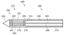
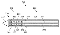
본 발명의 제1 양태에 따르면, 전기 외과 기구로서: 마이크로파 에너지 및/또는 라디오 주파수 에너지를 전달하기 위한 동축 피드 케이블로서, 내측 도전체, 외측 도전체 및 상기 내측 도전체 및 상기 외측 도전체를 분리하는 유전체 물질을 갖는, 상기 동축 피드 케이블; 및 상기 동축 피드 케이블의 원단에 배치되어 상기 마이크로파 에너지 및/또는 상기 라디오 주파수 에너지를 수용하기 위한 방사 팁으로서: 상기 방사 팁의 외면으로부터 상기 동축 피드 케이블로부터 수용된 상기 마이크로파 에너지 및/또는 상기 라디오 주파수 에너지를 전달하도록 구성된 에너지 전달 구조체로서, 상기 내측 도전체에 전기적으로 연결되고 상기 동축 피드 케이블의 상기 원단을 너머 길이 방향으로 연장되는 세장형 도전체를 포함하는, 상기 에너지 전달 구조체; 및 상기 세장형 도전체 주위에 배치되는 유전체 바디를 포함하는, 상기 방사 팁을 포함하며, 상기 유전체 바디는 그 안에 공동을 포함하며, 상기 공동은 상기 세장형 도전체에 인접하게 배치되어 상기 방사 팁이 굴곡될 수 있게 하는, 전기 외과 기구가 제공된다.According to a first aspect of the invention, there is provided an electrical surgical instrument comprising: a coaxial feed cable for transmitting microwave energy and/or radio frequency energy, wherein the inner conductor, the outer conductor and the inner conductor and the outer conductor are separated. The coaxial feed cable having a dielectric material; And a radiation tip disposed on a distal end of the coaxial feed cable to receive the microwave energy and/or the radio frequency energy: the microwave energy and/or the radio frequency energy received from the coaxial feed cable from an outer surface of the radiation tip. An energy transfer structure configured to transmit a signal, the energy transfer structure comprising an elongate conductor electrically connected to the inner conductor and extending in a longitudinal direction beyond the distal end of the coaxial feed cable; And a dielectric body disposed around the elongate conductor, wherein the dielectric body includes a cavity therein, and the cavity is disposed adjacent to the elongate conductor so that the radiating tip An electrical surgical instrument is provided that allows it to be bent.
에너지 전달 구조는 마이크로파 에너지만 또는 무선 주파수 에너지만 전달하도록 구성될 수 있다. 그리고 실시 예들에서, 에너지 전달 구조는 마이크로파 및 무선 주파수 에너지를 별개로 또는 동시에 전달할 수 있도록 구성될 수 있다. 세장형 도전체는 마이크로파 에너지를 방사하기 위한 안테나로 구성될 수 있거나, 라디오 주파수 에너지를 전달하기 위해 능동 전극에 전기적 연결을 제공하는(예를 들어, 외측 도전체에 연결된 리턴 전극과 조합하여) 수단으로 구성될 수 있다.The energy transfer structure may be configured to transfer only microwave energy or radio frequency energy. And in embodiments, the energy transfer structure may be configured to transfer microwave and radio frequency energy separately or simultaneously. The elongate conductor may consist of an antenna for radiating microwave energy, or a means of providing an electrical connection to the active electrode (e.g. in combination with a return electrode connected to the outer conductor) to transmit radio frequency energy. It can be composed of.
전기 외과 기구는 특히 폐 또는 자궁과 같이 인체의 제한되거나 접근하기 어려운 위치들의 조직을 절제하는데 적합할 수 있다. 그러나, 기구는 다른 장기들의 조직을 절제하는데 사용될 수도 있음을 이해할 수 있다.The electrosurgical instrument may be particularly suitable for ablation of tissue in restricted or inaccessible locations of the human body, such as the lung or uterus. However, it will be appreciated that the instrument may also be used to ablate the tissues of other organs.
동축 피드 케이블은 일단에서 전기 외과 발생기에 연결 가능한 통상적인 저손실 동축 케이블일 수 있다. 특히, 내측 도전체는 동축 피드 케이블의 길이 방향 축을 따라 연장되는 세장형 도전체일 수 있다. 유전체 물질은 내측 도전체 주위에 배치될 수 있다, 예를 들어, 제1 유전체 물질은 내측 도전체가 관통 연장되는 채널을 가질 수 있다. 외측 도전체는 유전체 물질의 표면 상에 배치되는 도전성 물질로 만들어진 슬리브일 수 있다. 동축 피드 케이블은 케이블을 절연하고 보호하기 위한 외측 보호 시스를 더 포함할 수 있다. 일부 예에서, 보호 시스는 조직이 케이블에 점착되는 것을 방지하기 위해 비점착성 물질로 만들어지거나 코팅될 수 있다. 방사 팁은 동축 피드 케이블의 원단에 위치되고, 동축 피드 케이블을 따라 전달되는 EM 에너지를 타겟 조직으로 전달하는 역할을 한다. 방사 팁은 동축 피드 케이블에 영구적으로 부착될 수 있거나, 또는 그것은 동축 피드 케이블에 착탈 가능하게 부착될 수 있다. 예를 들어, 방사 팁을 수용하고 필요한 전기 연결부들을 형성하도록 배열되는 커넥터가 동축 피드 케이블의 원단에 제공될 수 있다.The coaxial feed cable may be a conventional low loss coaxial cable connectable at one end to an electric surgical generator. In particular, the inner conductor may be an elongated conductor extending along the longitudinal axis of the coaxial feed cable. The dielectric material may be disposed around the inner conductor, for example, the first dielectric material may have a channel through which the inner conductor extends. The outer conductor may be a sleeve made of a conductive material disposed on the surface of the dielectric material. The coaxial feed cable may further include an outer protective sheath to insulate and protect the cable. In some examples, the protective sheath may be made of or coated with a non-stick material to prevent the tissue from sticking to the cable. The spinning tip is located at the far end of the coaxial feed cable and serves to transfer EM energy transmitted along the coaxial feed cable to the target tissue. The spinning tip may be permanently attached to the coaxial feed cable, or it may be detachably attached to the coaxial feed cable. For example, a connector arranged to receive the spinning tip and to form the necessary electrical connections may be provided on the far end of the coaxial feed cable.
유전체 바디는 세장형 도전체를 전달하기 위한 채널을 포함할 수 있다. 기구는 세장형 도전체를 채널을 통해 넣거나 세장형 도전체 상에 유전체를 증착하여 조립될 수 있다.The dielectric body may include a channel for transmitting the elongated conductor. The appliance can be assembled by inserting an elongate conductor through a channel or by depositing a dielectric over the elongate conductor.
유전체 바디는 일반적으로 원통형일 수 있지만, 다른 형상들도 가능하다. 유전체 바디는 동축 피드 케이블의 원단에 부착될 수 있다. 일부 예에서, 유전체 바디는 동축 피드 케이블의 원단을 너머 연장되는 동축 피드 케이블의 유전체 물질의 돌출 부분을 포함할 수 있다. 이는 방사 팁의 구성을 단순화하고, 방사 팁과 동축 피드 케이블 사이의 경계에서 EM 에너지의 반사를 방지할 수 있다. 다른 예들에서는, 동축 피드 케이블의 유전체 물질와 분리되는 제2 유전체 물질이 유전체 바디를 형성하는데 사용될 수 있다. 제2 유전체 물질은 동축 피드 케이블의 유전체 물질과 동일하거나, 또는 상이할 수 있다. 제2 유전체 물질은 마이크로파 에너지가 타겟 조직으로 전달되는 효율을 개선하기 위해 타겟 조직과의 임피던스 정합을 개선하도록 선택될 수 있다. 유전체 바디는 또한 원하는 방식으로 방사 프로파일을 형성하도록 선택 및 배열되는 유전체 물질의 다수의 상이한 조각들을 포함할 수 있다. 유전체 바디는 조직이 그것에 점착되는 것을 방지하기 위해 비점착성 물질(예를 들어, PTFE)로 만들어지거나 코팅될 수 있다.The dielectric body can generally be cylindrical, but other shapes are possible. The dielectric body may be attached to the distal end of the coaxial feed cable. In some examples, the dielectric body may include a protruding portion of the dielectric material of the coaxial feed cable extending beyond the distal end of the coaxial feed cable. This simplifies the construction of the radiating tip and can prevent the reflection of EM energy at the boundary between the radiating tip and the coaxial feed cable. In other examples, a second dielectric material that is separate from the dielectric material of the coaxial feed cable may be used to form the dielectric body. The second dielectric material may be the same as or different from the dielectric material of the coaxial feed cable. The second dielectric material may be selected to improve impedance matching with the target tissue to improve the efficiency at which microwave energy is delivered to the target tissue. The dielectric body may also include a number of different pieces of dielectric material selected and arranged to form the radiation profile in a desired manner. The dielectric body may be made of or coated with a non-stick material (eg, PTFE) to prevent the tissue from sticking to it.
유전체 바디는 길이 방향, 즉, 동축 피드 케이블의 길이 방향 축에 평행 한 방향으로 연장된다. 세장형 도전체는 유전체 바디의 채널 내에서 연장된다. 채널은 유전체 바디의 일 부분을 통해 연장되는 통로일 수 있다. 세장형 도전체는 세장형 형상을 갖는 임의의 적합한 도전체일 수 있다. 예를 들어, 세장형 도전체는 유전체 바디 내에서 연장되는 도전성 물질의 와이어, 로드 또는 스트립일 수 있다. 일부 실시 예에서, 세장형 도전체는 동축 피드 케이블의 원단을 너머 연장되는 내측 도전체의 원위부일 수 있다. 다시 말해, 내측 도전체는 동축 피드 케이블의 원단을 너머 유전체로 연장되어 세장형 도전체를 형성할 수 있다. 이는 내측 도전체의 원단에 별도의 도전체를 연결할 필요가 없기 때문에, 동축 피드 케이블의 원단에 방사 팁을 형성하는 것을 가능하게 할 수 있다.The dielectric body extends in the longitudinal direction, ie in a direction parallel to the longitudinal axis of the coaxial feed cable. The elongate conductor extends within the channel of the dielectric body. The channel may be a passage extending through a portion of the dielectric body. The elongate conductor can be any suitable conductor having an elongate shape. For example, the elongate conductor may be a wire, rod or strip of conductive material extending within the dielectric body. In some embodiments, the elongated conductor may be the distal portion of the inner conductor extending beyond the distal end of the coaxial feed cable. In other words, the inner conductor may extend beyond the distal end of the coaxial feed cable to the dielectric to form an elongate conductor. This makes it possible to form a spinning tip on the distal end of the coaxial feed cable, since it is not necessary to connect a separate conductor to the distal end of the inner conductor.
방사 팁은 마이크로파 방사기로 작용하도록 구성될 수 있다, 즉, 그것은 동축 피드 케이블에 의해 전달되는 마이크로파 에너지를 방사하도록 구성될 수 있다. 특히, 동축 피드 케이블로부터 방사 팁으로 전달되는 마이크로파 에너지는 세장형 도전체의 길이를 따라 방사될 수 있다. 외측 도전체는 세장형 도전체가 외측 도전체의 원단을 너머 연장되도록, 동축 피드 케이블의 원단에서 끝날 수 있다. 이러한 방식으로, 방사 팁은 마이크로파 모노폴 안테나 역할을 할 수 있다. 그에 따라, 방사 팁으로 전달되는 마이크로파 에너지가 세장형 도전체로부터 주변 타겟 조직으로 방사될 수 있다.The radiating tip may be configured to act as a microwave emitter, ie it may be configured to radiate microwave energy delivered by a coaxial feed cable. In particular, microwave energy transferred from the coaxial feed cable to the radiating tip can be radiated along the length of the elongated conductor. The outer conductor may end at the far end of the coaxial feed cable so that the elongated conductor extends beyond the far end of the outer conductor. In this way, the radiating tip can act as a microwave monopole antenna. Accordingly, microwave energy delivered to the radiation tip can be radiated from the elongated conductor to the surrounding target tissue.
추가적으로 또는 대안적으로, 방사 팁은 RF 에너지를 사용하여 타겟 조직을 절개 또는 절제하도록 구성될 수 있다. 예를 들어, 방사 팁은 타겟 조직을 절개 또는 절제하도록 배열된 노출된 전극(예를 들어, 양극성 RF 전극) 쌍을 포함할 수 있다. 전극들 중 하나는 내측 도전체에 전기적으로 연결될 수 있고(예를 들어, 세장형 도전체를 통해), 전극들 중 다른 하나는 외측 도전체에 전기적으로 연결될 수 있다. 이러한 방식으로, 라디오 주파수 에너지를 근위 및 원위 전극들로 전달함으로써, 전극들 사이 또는 그 주위에 위치되는 생체 조직이 절개 및/또는 절제될 수 있다. 일부 경우에, 방사 팁은 마이크로파 및 RF 에너지 양자를 별개로 또는 동시에 전달하도록 구성될 수 있다. 이는 RF 및 마이크로파 에너지의 인가를 전환하거나 변경함으로써, 전기 외과 기구의 기능을 빠르게 변경할 수 있다.Additionally or alternatively, the radiating tip can be configured to cut or ablate the target tissue using RF energy. For example, the radiation tip may include a pair of exposed electrodes (eg, bipolar RF electrodes) arranged to cut or ablate the target tissue. One of the electrodes can be electrically connected to the inner conductor (eg, via an elongated conductor) and the other of the electrodes can be electrically connected to the outer conductor. In this way, by transferring radio frequency energy to the proximal and distal electrodes, biological tissue located between or around the electrodes can be excised and/or ablated. In some cases, the radiating tip may be configured to deliver both microwave and RF energy separately or simultaneously. It can quickly change the function of the electrosurgical instrument by switching or changing the application of RF and microwave energy.
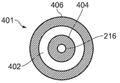
공동은 세장형 도전체 주위에 배치되는 유전체 바디의 부분에 형성될 수 있다, 즉, 공동은 세장형 도전체가 관통 연장되는 채널을 갖는 유전체 바디의 부분에 위치될 수 있다. 공동은 길이 방향에 수직인 측면(예를 들어, 방사) 방향으로 채널로부터 이격될 수 있다. 예를 들어, 유전체 바디가 원통형인 경우, 채널의 중심이 실질적으로 원통형 바디의 중심 축 상에 놓일 수 있고, 공동은 채널로부터 방사상으로 이격될 수 있다. 공동은 예를 들어, 유전체 바디 내에, 또는 그것의 표면 상에 형성되는 공극, 예를 들어, 유전체 바디의 유전체 물질이 없는 영역일 수 있다,. 예를 들어, 공동은 유전체 바디의 표면 상의 만입부 또는 오목부일 수 있다. 공동은 유전체 바디의 외면에 형성될 수 있다. 대안적으로, 공동은 유전체 바디의 내면에, 예를 들어, 채널의 벽에 형성될 수 있다. 공동이 유전체 바디 내에 형성되는 경우, 공동은 유전체 바디 내에 둘러싸인 공극 또는 포켓일 수 있다.The cavity may be formed in a portion of the dielectric body disposed around the elongate conductor, ie the cavity may be located in a portion of the dielectric body having a channel through which the elongate conductor extends. The cavity may be spaced from the channel in a lateral (eg radial) direction perpendicular to the longitudinal direction. For example, if the dielectric body is cylindrical, the center of the channel can lie substantially on the central axis of the cylindrical body, and the cavity can be radially spaced from the channel. The cavities can be, for example, voids formed within the dielectric body, or on a surface thereof, eg, a region free of dielectric material of the dielectric body. For example, the cavity may be an indentation or a recess on the surface of the dielectric body. The cavity may be formed on the outer surface of the dielectric body. Alternatively, the cavity may be formed on the inner surface of the dielectric body, for example in the wall of the channel. When the cavity is formed within the dielectric body, the cavity may be a void or pocket enclosed within the dielectric body.
공동은 세장형 도전체를 둘러싸는 유전체 바디의 부분의 물질의 양을 감소시킬 수 있다. 예를 들어, 공동은 세장형 도전체를 둘러싸는 유전체 바디의 부분에서 유전체 바디를 형성하는 물질의 측면 방향의 총 두께를 감소시킬 수 있다. 이는 세장형 도전체 주위 유전체 바디의 강성을 감소시킬 수 있다. 공동은 또한 유전체 바디의 절곡을 가능하게 하는 절곡 지점 또는 굴곡 역할을 할 수 있다. 따라서 공동은 유전체 바디의 가요성을 증가시키는 역할을 할 수 있다. 이는 방사 팁의 절곡을 가능하게 할 수 있으며, 이는 다시 신체의 좁고 구불구불한 통로들을 통해 전기 외과 기구를 가이딩하는 것을 가능하게 할 수 있다. 이는 타겟 조직에 에너지의 효율적인 전달을 보장하기 위해, 방사 팁이 타겟 조직에 가능한 한 가깝게 위치될 수 있게 할 수 있다. 공동의 체적은 유전체 물질의 전체 체적에 비해 상대적으로 작을 수 있다. 이러한 방식으로, 공동은 유전체 바디의 임피던스 매칭 속성들에 큰 영향을 미치지 않으면서 유전체 바디의 가요성을 개선할 수 있다. 그에 따라, 방사 팁의 방사 프로파일은 공동의 존재에 의해 크게 영향을 받지 않을 수 있다.The cavity can reduce the amount of material in the portion of the dielectric body surrounding the elongate conductor. For example, the cavity may reduce the total thickness in the lateral direction of the material forming the dielectric body in the portion of the dielectric body surrounding the elongate conductor. This can reduce the stiffness of the dielectric body around the elongate conductor. The cavity may also serve as a bend point or bend to allow for bending of the dielectric body. Thus, the cavity can serve to increase the flexibility of the dielectric body. This may enable bending of the spinning tip, which in turn may make it possible to guide the electrosurgical instrument through the narrow, serpentine passages of the body. This may allow the radiation tip to be positioned as close as possible to the target tissue to ensure efficient delivery of energy to the target tissue. The volume of the cavity can be relatively small compared to the total volume of the dielectric material. In this way, the cavity can improve the flexibility of the dielectric body without significantly affecting the impedance matching properties of the dielectric body. Accordingly, the spinning profile of the spinning tip may not be significantly affected by the presence of the cavity.
공동은 비어 있을 수 있다(예를 들어, 그것은 공기로 채워질 수 있다). 일부 경우에, 공동은 유전체 바디의 가요성을 개선하기 위해 변형 가능한 물질로 채워질 수 있다.The cavity may be empty (eg it may be filled with air). In some cases, the cavity may be filled with a deformable material to improve the flexibility of the dielectric body.
일부 경우에, 유전체 바디에 다수의 공동이 형성될 수 있다. 공동들은 유전체의 길이를 따라 배열될 수 있다, 예를 들어, 그것들은 길이 방향으로 이격될 수 있다. 이는 유전체 바디의 길이를 따라 복수의 절곡 지점을 제공하여, 유전체 바디의 길이를 따라 그것의 절곡을 가능하게 할 수 있다. 공동들은 또한 유전체 바디의 길이 방향 축 주위에 배열될 수도 있다. 이는 길이 방향에 비해 상이한 방향들로 유전체 바디의 절곡을 가능하게 할 수 있다. 그에 따라, 다수의 공동을 갖는 것은 유전체 바디의 가요성을 더욱 개선할 수 있다. 다수의 공동은 균일하게 이격될 수 있거나, 또는 그것들은 임의의 방식으로 배열될 수 있다. 공동들은 특정 방향으로 유전체 바디의 절곡을 가능하게 하도록 유전체 바디 상에 배치될 수 있다. 예를 들어, 유전체 바디의 측면 상에 공동을 배치하면 예를 들어, 공동을 갖는 측면 상의 유전체의 강성을 감소시킴으로써, 유전체 바디를 그러한 측면을 향한 절곡을 가능하게 할 수 있다. 유전체 바디의 다수의 방향으로의 절곡을 가능하게 하기 위해서는, 유전체 바디의 길이 방향 축 주위에 다수의 공동이 배열될 수 있다.In some cases, multiple cavities may be formed in the dielectric body. The cavities can be arranged along the length of the dielectric, for example they can be spaced longitudinally. This can provide a plurality of bending points along the length of the dielectric body, allowing its bending along the length of the dielectric body. The cavities may also be arranged around the longitudinal axis of the dielectric body. This can enable bending of the dielectric body in different directions compared to the longitudinal direction. Accordingly, having multiple cavities can further improve the flexibility of the dielectric body. The multiple cavities can be evenly spaced, or they can be arranged in any way. The cavities may be disposed on the dielectric body to allow bending of the dielectric body in a specific direction. For example, placing a cavity on the side of the dielectric body may enable bending of the dielectric body towards that side, for example by reducing the stiffness of the dielectric on the side with the cavity. In order to enable bending of the dielectric body in multiple directions, multiple cavities may be arranged around the longitudinal axis of the dielectric body.
공동(또는 공동들)은 유전체 바디의 제조 동안 형성될 수 있다. 예를 들어, 유전체 바디는 하나 이상의 공동을 포함하도록 몰딩될 수 있다. 대안적으로, 공동들은 유전체 바디에 홀들을 뚫고 및/또는 유전체 바디의 부분들을 기계 가공함으로써 형성될 수 있다.The cavities (or cavities) may be formed during manufacture of the dielectric body. For example, the dielectric body can be molded to include one or more cavities. Alternatively, the cavities may be formed by drilling holes in the dielectric body and/or machining portions of the dielectric body.
일부 실시 예에서, 공동은 유전체 바디에 길이 방향으로 연장되는 루멘에 의해 형성될 수 있다. 유전체 바디는 세장형 도전체를 둘러싸는 내측 슬리브를 포함(즉, 세장형 도전체가 연장되는 채널을 제공)할 수 있다. 루멘은 내측 슬리브의 방사상 두께만큼 세장형 도전체로부터 이격될 수 있다. 루멘은 유전체 바디의 가요성을 개선하기 위해, 유전체 바디의 전부 또는 일 부분을 따라 연장될 수 있다. 루멘은 유전체 바디의 일 부분을 통해 연장되는 통로 또는 채널일 수 있다. 루멘은 폐쇄된 루멘일 수 있다, 즉, 그것은 유전체 바디 내부에 형성될 수 있다. 대안적으로, 루멘은 개방 루멘일 수 있다, 즉, 그것은 유전체 바디의 표면에 형성될 수 있다. 일부 예에서, 루멘은 유전체 바디에서 채널에 평행할 수 있다. 다른 예들에서, 루멘은 그것이 유전체 바디의 채널 주위를 감도록 나선형 형상을 가질 수 있다. 루멘은 원형 단면을 가질 수 있거나, 또는 그것은 다른 형상의 단면을 가질 수 있다. 바람직하게는, 루멘은 방사 팁을 통해 배선 또는 다른 입력들을 전달하는데 사용될 수 있다. 유전체 바디의 루멘은 입력이 전기 외과 기구의 근단으로부터 방사 팁으로 공급될 수 있도록, 동축 피드 케이블의 루멘과 연속적일 수 있다. 예를 들어, 루멘은 유체(예를 들어, 팁을 냉각하기 위한 냉각 유체)를 전달하는데 사용될 수 있다. 루멘은 제어 와이어를 전달하는데 사용될 수 있다(예를 들어, 방사 팁의 원단에 위치되는 블레이드 또는 다른 메커니즘을 제어하기 위해).In some embodiments, the cavity may be formed by a lumen extending longitudinally in the dielectric body. The dielectric body may include an inner sleeve surrounding the elongate conductor (ie, providing a channel through which the elongate conductor extends). The lumen can be spaced from the elongate conductor by the radial thickness of the inner sleeve. The lumen may extend along all or a portion of the dielectric body to improve the flexibility of the dielectric body. The lumen may be a passage or channel extending through a portion of the dielectric body. The lumen can be a closed lumen, ie it can be formed inside the dielectric body. Alternatively, the lumen can be an open lumen, ie it can be formed on the surface of the dielectric body. In some examples, the lumen can be parallel to the channels in the dielectric body. In other examples, the lumen can have a helical shape such that it wraps around a channel of the dielectric body. The lumen may have a circular cross section, or it may have a cross section of another shape. Advantageously, the lumen can be used to convey wiring or other inputs through the radiating tip. The lumen of the dielectric body can be continuous with the lumen of the coaxial feed cable so that input can be supplied from the proximal end of the electrosurgical instrument to the radiating tip. For example, the lumen can be used to deliver a fluid (eg, a cooling fluid to cool the tip). The lumen can be used to deliver a control wire (eg, to control a blade or other mechanism positioned at the distal end of the spinning tip).
유전체 바디에 길이 방향으로 연장되는 다수의 루멘이 있을 수 있다(예를 들어, 다중 공동이 있는 경우). 루멘들은 그것들이 유전체 바디의 채널 주위로 이격되도록 배열될 수 있다, 예를 들어, 그것들은 채널 주위에 균등하게 이격될 수 있다. 이는 다수의 방향에서 길이 방향 축에 대한 방사 팁의 절곡을 가능하게 할 수 있다.There may be multiple lumens extending longitudinally in the dielectric body (eg, if there are multiple cavities). The lumens can be arranged such that they are spaced around the channel of the dielectric body, for example they can be evenly spaced around the channel. This may enable bending of the spinning tip about the longitudinal axis in a number of directions.
일부 실시 예에서, 루멘은 채널이 형성되는 유전체 바디의 일 부분을 둘러싸는 환형 단면을 가질 수 있다. 다시 말해, 유전체는 세장형 도전체를 포함하는 채널이 형성되는 내측 부분, 및 내측 부분 주위에 슬리브를 형성하는 외측 부분을 포함할 수 있다. 외측 부분은 내측 부분으로부터 이격되어, 내측 부분과 외측 부분 사이에 루멘을 형성할 수 있다. 예를 들어, 외측 부분이 스페이서를 사용하여 내측 부분으로부터 이격될 수 있다. 유전체 바디의 내측 부분을 둘러싸는 환형 단면을 갖는 루멘을 제공함으로써, 유전체 바디의 길이 방향 축 주위에 공동이 효과적으로 형성될 수 있다. 이는 유전체 바디의 강성이 길이 방향 축에 대해 실질적으로 대칭이 되게 할 수 있으며, 이는 예를 들어, 길이 방향 축에 대한 유전체 바디의 절곡을 가능하게 할 수 있다, 예를 들어, 우선적인 절곡 방향이 없을 수 있다. 루멘은 그 환형 단면의 중심이 실질적으로 유전체 바디의 길이 방향 축에 놓여, 루멘이 길이 방향 축에 대해 축 대칭이 되도록 배열될 수 있다. 이는 길이 방향 축에 대한 유전체 바디의 강성의 등방성을 더욱 개선할 수 있다.In some embodiments, the lumen may have an annular cross section surrounding a portion of the dielectric body in which the channel is formed. In other words, the dielectric may include an inner portion where a channel including an elongate conductor is formed, and an outer portion that forms a sleeve around the inner portion. The outer portion may be spaced apart from the inner portion to form a lumen between the inner portion and the outer portion. For example, the outer portion can be spaced apart from the inner portion using a spacer. By providing a lumen having an annular cross section surrounding an inner portion of the dielectric body, a cavity can be effectively formed around the longitudinal axis of the dielectric body. This can cause the stiffness of the dielectric body to be substantially symmetrical about the longitudinal axis, which can, for example, enable bending of the dielectric body about the longitudinal axis, e.g. the preferential bending direction is It may not be. The lumens may be arranged such that the center of the annular cross section lies substantially on the longitudinal axis of the dielectric body, so that the lumen is axially symmetric about the longitudinal axis. This can further improve the isotropy of the stiffness of the dielectric body with respect to the longitudinal axis.
일부 실시 예에서, 루멘은 유전체 바디의 외면에 배치될 수 있다. 예를 들어, 그것은 유전체 바디의 외면 상에 길이 방향으로 연장되는 홈을 형성할 수 있다. 그에 따라 루멘은 유전체 바디의 외면 상의 개방 루멘이 될 수 있다. 유전체 바디가 다수의 공동을 포함하는 경우, 다수의 홈이 외면 상에 형성될 수 있다. 방사 팁의 절곡을 가능하게 하는 것 외에도, 홈들은 맞물림 피처들의 역할을 할 수 있다. 예를 들어, 전기 외과 기구의 외측 보호 시스는 방사 팁에 대해 외측 보호 시스를 고정하기 위해, 홈들에 맞물리는 하나 이상의 돌출부를 가질 수 있다. 다른 예에서, 홈들은 외과 관찰 디바이스의 기구 채널을 따라 방사 팁을 가이딩하고/거나 방사 팁의 원하는 배향을 유지하는데 사용될 수 있다. 유전체 바디의 표면 상의 홈들은 예를 들어, 방사 팁을 회전시키기 위해, 방사 팁을 파지하는데 사용될 수도 있다.In some embodiments, the lumen may be disposed on the outer surface of the dielectric body. For example, it can form a groove extending longitudinally on the outer surface of the dielectric body. Accordingly, the lumen can be an open lumen on the outer surface of the dielectric body. When the dielectric body includes a plurality of cavities, a plurality of grooves may be formed on the outer surface. In addition to enabling bending of the spinning tip, the grooves can serve as engagement features. For example, the outer protective sheath of an electrosurgical instrument may have one or more protrusions that engage the grooves to secure the outer protective sheath to the spinning tip. In another example, the grooves may be used to guide the spinning tip along the instrument channel of the surgical observation device and/or to maintain a desired orientation of the spinning tip. The grooves on the surface of the dielectric body may be used to grip the spinning tip, for example to rotate the spinning tip.
일부 실시 예에서, 공동은 유전체 바디에 오목부에 의해 형성될 수 있다. 오목부는 유전체 바디의 표면에 형성될 수 있다. 오목부는 유전체 바디의 표면에 형성되는 만입부 또는 노치일 수 있다. 오목부는 유전체 바디의 절곡 지점 또는 굴곡 역할을 할 수 있다, 예를 들어, 그거은 유전체 바디의 다른 영역들에 비해 절곡에 대한 저항이 감소된 영역을 구성할 수 있다(예를 들어, 오목부에서 유전체 바디의 두께 감소로 인해). 오목부의 길이는 길이 방향에 대한 유전체 바디의 절곡을 가능하게 하기 위해, 길이 방향에 수직일 수 있다. 다수의 절곡 지점 또는 굴곡을 제공하기 위해 다수의 오목부가 유전체 바디에 형성될 수 있다. 제1 양태에서, 이는 방사 팁의 절곡을 가능하게 하기 위해 방사 팁에 유전체 물질을 성형함으로써 달성된다.In some embodiments, the cavity may be formed by a recess in the dielectric body. The recess may be formed on the surface of the dielectric body. The concave portion may be an indentation portion or a notch formed on the surface of the dielectric body. The concave portion may serve as a bending point or bend of the dielectric body. For example, the concave portion may constitute a region in which resistance to bending is reduced compared to other regions of the dielectric body (e.g., dielectric Due to the reduced thickness of the body). The length of the recess may be perpendicular to the length direction, to enable bending of the dielectric body with respect to the length direction. A number of recesses may be formed in the dielectric body to provide a number of bending points or bends. In a first aspect, this is achieved by molding a dielectric material in the spinning tip to enable bending of the spinning tip.
일부 실시 예에서, 오목부는 유전체 바디의 외면에 형성될 수 있다. 다른 실시 예들에서, 오목부는 유전체 바디의 내면에, 예를 들어, 유전체 바디의 채널의 벽에 형성될 수 있다. 다수의 오목부가 있는 경우, 일부 오목부는 외면에 형성될 수 있는 한편, 일부 오목부는 내면에 형성될 수 있다.In some embodiments, the concave portion may be formed on the outer surface of the dielectric body. In other embodiments, the recess may be formed on the inner surface of the dielectric body, for example in the wall of the channel of the dielectric body. When there are multiple concave portions, some concave portions may be formed on the outer surface, while some concave portions may be formed on the inner surface.
일부 실시 예에서, 오목부는 유전체 바디의 원주 주위로 연장되는 홈을 형성할 수 있다. 홈은 유전체 바디의 외면에 형성될 수 있다. 홈은 유전체 바디의 원주 주위에 루프 또는 링을 형성할 수 있다. 이 경우, 홈은 길이 방향에 수직한 방향으로 배향될 수 있다. 다른 경우들에, 홈은 그것이 유전체 바디의 길이를 따라 유전체 바디 주위를 감도록 나선형 형상을 가질 수 있다. 유전체 바디의 원주 주위에 홈을 형성함으로써, 유전체 바디의 강성은 길이 방향 축에 대해 실질적으로 대칭일 수 있다. 이는 길이 방향 축에 대해 유전체 바디의 절곡을 가능하게 할 수 있다.In some embodiments, the concave portion may form a groove extending around the circumference of the dielectric body. The groove may be formed on the outer surface of the dielectric body. The groove can form a loop or ring around the circumference of the dielectric body. In this case, the grooves may be oriented in a direction perpendicular to the length direction. In other cases, the groove may have a helical shape such that it wraps around the dielectric body along the length of the dielectric body. By forming a groove around the circumference of the dielectric body, the stiffness of the dielectric body can be substantially symmetrical about the longitudinal axis. This may enable bending of the dielectric body about the longitudinal axis.
일부 실시 예에서, 유전체 바디는 골형 표면을 포함할 수 있고, 오목부는 골형 표면의 골들에 의해 형성될 수 있다. 유전체 바디의 외면이 골형일 수 있고/있거나, 내면(채널의 벽)이 골형일 수 있다. 일부 경우에, 유전체 바디의 외면과 내면이 모두 골형일 수 있다. 예를 들어, 유전체 바디의 일 부분은 골형 관 또는 파이프의 길이에 의해 형성될 수 있다. 적합한 골형 관 또는 파이프들은 PTFE, FEP 또는 PFA로 만들어질 수 있다. 골형 표면은 일련의 정점 및 저점을 형성하도록 배열되는 일련의 골 및 이랑을 포함할 수 있다. 오목부는 인접한 골들/이랑들 사이에 형성되는 저점에 대응할 수 있다. 골형 표면은 다수의 골을 포함할 수 있으므로, 골형 표면에 다수의 오목부가 형성될 수 있다. 오목부들은 상술된 바와 같이, 유전체 바디에 대한 절곡 지점 또는 굴곡 역할을 할 수 있다. 골형 관은 상업적으로 폭넓게 이용 가능하다. 이는 저렴한 비용으로 유연한 방사 팁의 생산을 가능하게 할 수 있다.In some embodiments, the dielectric body may include a bone-like surface, and the concave portion may be formed by the bones of the bone-like surface. The outer surface of the dielectric body may be bone-like, and/or the inner surface (wall of the channel) may be bone-like. In some cases, both the outer and inner surfaces of the dielectric body may be bone-like. For example, a portion of the dielectric body may be formed by the length of a bone-shaped tube or pipe. Suitable corrugated tubes or pipes may be made of PTFE, FEP or PFA. The bone-like surface may comprise a series of bones and gyrus arranged to form a series of vertices and troughs. The concave portion may correspond to a low point formed between adjacent valleys/gyruses. Since the bone-like surface may include a plurality of bones, a plurality of recesses may be formed in the bone-like surface. As described above, the concave portions may serve as a bending point or a bend for the dielectric body. Bone tube is widely available commercially. This can enable the production of flexible spinning tips at low cost.
일부 실시 예에서, 상기 방사 팁은 상기 유전체 바디의 외면 주위에 배치되는 외측 시스를 더 포함할 수 있으며, 상기 외측 시스와 상기 유전체 바디 사이의 상대적인 움직임을 가능하게 하도록 상기 유전체 바디로부터 떨어져 있다. 외측 시스는 방사 팁을 환경으로부터 보호하고 절연하는 역할을 할 수 있다. 외측 시스는 조직이 그것에 점착되는 것을 방지하기 위해 비점착성 물질(예를 들어, PTFE)로 만들어지거나 코팅될 수 있다. 외측 시스는 유전체 바디의 외면을 커버하는 절연 물질의 슬리브일 수 있다. 예를 들어, 외측 시스는 유전체 바디 주위에 수축된 열 수축 관의 길이에 의해 형성될 수 있다. 외측 시스는 유전체 바디와 분리되며, 이는 그것이 유전체 바디 별도로 형성된다는 것을 의미한다. 즉, 그것들은 별개의 구성요소들로 형성된다. 뿐만 아니라, 외측 시스를 유전체 바디에 고정하는 접착제 또는 다른 연결 수단이 없을 수 있다. 외측 시스는 외측 시스와 유전체 바디 사이의 마찰력을 통해 유전체 바디 상에 홀딩될 수 있다. 그 결과, 유전체 바디의 외면과 외측 시스 사이의 소량의 상대적인 움직임이 가능할 수 있다. 이러한 방식으로, 유전체가 절곡될 때, 외측 시스는 유전체의 표면에 대해 이동할 수 있어, 외측 시스에 응력이 축적되는 것을 방지할 수 있다. 예를 들어, 외측 시스는 유전체 바디의 절곡의 내부 주위에서 "번치 업(bunch up)"할 수 있다. 그에 따라, 외측 시스는 방사 팁의 절곡에 대해 어떠한 상당한 저항도 제공하지 않을 수 있다, 즉, 외측 시스는 방사 팁의 강성을 크게 증가시키지 않을 수 있다. 따라서 유전체 바디와 별도로 외측 시스를 형성하면 방사 팁의 절곡이 가능해질 수 있다. 추가로, 이는 유전체 바디의 파손 및/또는 외측 시스의 인열을 유발할 수 있는, 유전체 바디와 외측 시스 사이의 인터페이스에의 응력 집중을 방지할 수 있다.In some embodiments, the radiating tip may further include an outer sheath disposed around an outer surface of the dielectric body, and away from the dielectric body to enable relative movement between the outer sheath and the dielectric body. The outer sheath can serve to protect and insulate the spinning tip from the environment. The outer sheath can be made or coated with a non-tacky material (eg PTFE) to prevent the tissue from sticking to it. The outer sheath may be a sleeve made of an insulating material covering the outer surface of the dielectric body. For example, the outer sheath can be formed by the length of a shrinked heat shrink tube around the dielectric body. The outer sheath is separated from the dielectric body, meaning that it is formed separately from the dielectric body. That is, they are formed of separate components. In addition, there may be no adhesive or other connecting means securing the outer sheath to the dielectric body. The outer sheath may be held on the dielectric body through frictional force between the outer sheath and the dielectric body. As a result, a small amount of relative movement between the outer surface and the outer sheath of the dielectric body may be possible. In this way, when the dielectric is bent, the outer sheath can move relative to the surface of the dielectric, thereby preventing stress from accumulating in the outer sheath. For example, the outer sheath can "bunch up" around the inside of the bend of the dielectric body. Accordingly, the outer sheath may not provide any significant resistance to bending of the spinning tip, ie the outer sheath may not significantly increase the stiffness of the spinning tip. Therefore, if the outer sheath is formed separately from the dielectric body, the radiation tip may be bent. Additionally, this can prevent stress concentration at the interface between the dielectric body and the outer sheath, which can cause breakage of the dielectric body and/or tearing of the outer sheath.
외측 시스는 동축 피드 케이블에 대한 위치를 고정하기 위해, 동축 피드 케이블의 원단에 일단이 부착될 수 있다. 예를 들어, 외측 시스는 동축 피드 케이블의 보호 시스에 부착될 수 있다. 일부 경우에, 외측 시스는 동축 피드 케이블의 보호 시스의 연속일 수 있다, 예를 들어, 외측 시스는 동축 피드 케이블의 원단을 너머 연장되는 동축 피드 케이블의 보호 시스의 원위부일 수 있다. 공동이 유전체 바디의 외면 상에 형성되는 경우, 외측 시스는 공동을 커버하는 역할을 할 수 있다. 이러한 방식으로, 방사 팁은 유전체 바디에 공동들이 있음에도 불구하고, 매끄러운 외면을 가질 수 있다.The outer sheath may have one end attached to the distal end of the coaxial feed cable to fix the position with respect to the coaxial feed cable. For example, the outer sheath can be attached to the protective sheath of a coaxial feed cable. In some cases, the outer sheath may be a continuation of the protective sheath of the coaxial feed cable, for example, the outer sheath may be the distal portion of the protective sheath of the coaxial feed cable extending beyond the distal end of the coaxial feed cable. When the cavity is formed on the outer surface of the dielectric body, the outer sheath may serve to cover the cavity. In this way, the spinning tip can have a smooth outer surface despite the cavities in the dielectric body.
외측 시스의 구성은 본 발명의 독립적인 양태를 제공할 수 있다. 이러한 양태에 따르면, 전기 외과 기구로서: 마이크로파 에너지 및/또는 라디오 주파수 에너지를 전달하기 위한 동축 피드 케이블로서, 내측 도전체, 외측 도전체 및 상기 내측 도전체 및 상기 외측 도전체를 분리하는 유전체 물질을 갖는, 상기 동축 피드 케이블; 및 상기 동축 피드 케이블의 원단에 배치되어 상기 마이크로파 에너지 및/또는 상기 라디오 주파수 에너지를 수용하기 위한 방사 팁으로서: 상기 방사 팁의 외면으로부터 상기 동축 피드 케이블로부터 수용된 상기 마이크로파 에너지 및/또는 상기 라디오 주파수 에너지를 전달하도록 구성된 에너지 전달 구조체로서, 상기 내측 도전체에 전기적으로 연결되고 상기 동축 피드 케이블의 상기 원단을 너머 길이 방향으로 연장되는 세장형 도전체를 포함하는, 상기 에너지 전달 구조체; 및 상기 세장형 도전체 주위에 배치되는 유전체 바디; 및 상기 유전체 바디의 외면 주위에 배치되는 외측 시스로서, 상기 외측 시스와 상기 유전체 바디 사이의 상대적인 움직임을 가능하게 하도록 상기 유전체 바디로부터 떨어져 있는, 상기 외측 시스를 포함하는, 상기 방사 팁을 포함하는, 전기 외과 기구가 제공된다.The configuration of the outer sheath can provide an independent aspect of the present invention. According to this aspect, as an electrosurgical instrument: a coaxial feed cable for transmitting microwave energy and/or radio frequency energy, comprising an inner conductor, an outer conductor and a dielectric material separating the inner conductor and the outer conductor. Having, the coaxial feed cable; And a radiation tip disposed on a distal end of the coaxial feed cable to receive the microwave energy and/or the radio frequency energy: the microwave energy and/or the radio frequency energy received from the coaxial feed cable from an outer surface of the radiation tip. An energy transfer structure configured to transmit a signal, the energy transfer structure comprising an elongate conductor electrically connected to the inner conductor and extending in a longitudinal direction beyond the distal end of the coaxial feed cable; And a dielectric body disposed around the elongate conductor. And an outer sheath disposed around an outer surface of the dielectric body, the radiating tip comprising the outer sheath, spaced apart from the dielectric body to enable relative movement between the outer sheath and the dielectric body. An electrical surgical instrument is provided.
본 발명의 제1 양태의 특징들은 본 발명의 제2 양태와 공유될 수 있고, 다시 논의되지 않는다. 특히, 본 발명의 제2 양태의 전기 외과 기구의 유전체 바디는 본 발명의 제1 양태과 관련하여 상술된 바와 같이, 공동(또는 다수의 공동)을 포함할 수 있다.Features of the first aspect of the invention can be shared with the second aspect of the invention and are not discussed again. In particular, the dielectric body of the electrosurgical instrument of the second aspect of the present invention may comprise a cavity (or multiple cavities), as described above with respect to the first aspect of the present invention.
상술된 본 발명의 제1 또는 제2 양태들 중 어느 하나의 실시 예들은 이하의 특징들을 포함할 수 있다.Embodiments of any one of the first or second aspects of the present invention described above may include the following features.
일부 실시 예에서, 상기 유전체 바디는 제1 유전체 물질로 형성되고, 상기 외측 시스는 상기 제1 유전체 물질과 상이한 제2 유전체 물질로 형성될 수 있다. 상기 제1 및 제2 유전체 물질들은 타겟 조직과 상기 방사 팁의 임피던스 정합을 개선하도록 선택될 수 있다. 상기 제1 및 제2 유전체 물질들은 또한 상기 방사 팁의 절곡을 가능하게 하도록 선택될 수도 있다. 예를 들어, 제2 유전체 물질이 제1 유전체 물질보다 더 낮은 강성을 가질 수 있다. 이는 외측 시스가 방사 팁의 전체 강성을 크게 증가시키지 않음을 보장할 수 있다.In some embodiments, the dielectric body may be formed of a first dielectric material, and the outer sheath may be formed of a second dielectric material different from the first dielectric material. The first and second dielectric materials may be selected to improve impedance matching between the target tissue and the radiation tip. The first and second dielectric materials may also be selected to enable bending of the radiating tip. For example, the second dielectric material may have a lower stiffness than the first dielectric material. This can ensure that the outer sheath does not significantly increase the overall stiffness of the spinning tip.
일부 실시 예에서, 상기 제1 유전체 물질은 상기 제2 유전체 물질보다 더 높은 용융 온도를 가질 수 있다. 이는 외측 시스가 유전체 바디 위에 제2 유전체 물질을 용융 또는 수축시킴으로써 형성될 수 있게 할 수 있다. 예를 들어, 외측 시스는 제2 유전체 물질로 만들어진 열 수축 물질의 관에 의해 형성될 수 있다. 열 수축 관은 유전체 바디 위에 배치된 다음 열을 가하여 유전체 위에 수축될 수 있다. 제1 유전체 물질의 용융 온도가 제2 유전체 물질의 용융 온도보다 높기 때문에, 유전체 바디는 그 위에 외측 시스가 형성될 때 용융되지 않는다. 이는 유전체 바디 위에 외측 시스가 잘 맞도록 보장하는 동시에, 그것들을 그것들 사이의 상대적인 움직임을 가능하게 하는 별도의 구성요소들로 유지할 수 있다. 이는 방사 팁의 제조를 가능하게 할 수 있다.In some embodiments, the first dielectric material may have a higher melting temperature than the second dielectric material. This may allow the outer sheath to be formed by melting or shrinking the second dielectric material over the dielectric body. For example, the outer sheath can be formed by a tube of heat shrinkable material made of a second dielectric material. A heat shrink tube can be placed over the dielectric body and then contracted over the dielectric by applying heat. Since the melting temperature of the first dielectric material is higher than the melting temperature of the second dielectric material, the dielectric body does not melt when an outer sheath is formed thereon. This ensures that the outer sheath fits over the dielectric body while keeping them as separate components that allow relative movement between them. This can make it possible to manufacture a spinning tip.
일부 실시 예에서, 제1 유전체 물질은 폴리테트라플루오로에틸렌(PTFE)일 수 있고 제2 유전체 물질은 플루오르화 에틸렌 프로필렌(FEP)일 수 있다. PTFE는 FEP보다 용융 온도가 높다. FEP는 일반적으로 PTFE보다 부드럽기 때문에, 쉽게 절곡 가능할 수 있다. 이러한 물질들의 조합을 사용하여, 외측 시스는 유전체 바디 위에 FEP를 용융시켜(예를 들어, 몰드를 사용하여), 유전체 상에 직접 외측 시스를 형성함으로써 형성될 수 있다. 대안적으로는, FEP로 만들어진 열 수축 관의 길이를 사용하여 유전체 위에 외측 시스를 형성할 수 있다.In some embodiments, the first dielectric material may be polytetrafluoroethylene (PTFE) and the second dielectric material may be fluorinated ethylene propylene (FEP). PTFE has a higher melting temperature than FEP. Since FEP is generally softer than PTFE, it can be easily bent. Using a combination of these materials, the outer sheath can be formed by melting the FEP over the dielectric body (eg, using a mold), thereby forming the outer sheath directly on the dielectric. Alternatively, a length of heat shrink tube made of FEP can be used to form an outer sheath over the dielectric.
일부 실시 예에서, 상기 외측 시스는 상기 유전체 바디의 원단을 커버하도록 배열된 원단 팁을 포함할 수 있다. 그에 따라, 외측 시스는 유전체 바디의 외면(예를 들어, 측면들) 및 원단 모두를 커버할 수 있다. 이러한 방식으로, 외측 시스는 유전체 바디 위에 캡을 형성할 수 있다. 말단 팁은 나머지 외측 시스(예를 들어, 제2 유전체 물질)와 동일한 유전체 물질로 만들어 질 수 있다. 원위 팁은 방사 팁의 타겟 조직 안으로 삽입할 수 있게 하기 위해 뾰족할 수 있다. 대안적으로, 원위 팁은 둥글거나 평평할 수도 있다. 원위 팁은 타겟 조직과의 임피던스 정합을 개선하는 역할을 할 수 있다. 원위 팁은 또한 방사 팁 주위 환경에 위치되는 유체가 외측 시스와 유전체 바디 사이의 공간(예를 들어, 공동)으로 들어가는 것을 방지하는 역할을 할 수도 있다.In some embodiments, the outer sheath may include a distal tip arranged to cover the distal end of the dielectric body. Accordingly, the outer sheath can cover both the outer surface (eg, side surfaces) and the distal end of the dielectric body. In this way, the outer sheath can form a cap over the dielectric body. The distal tip can be made of the same dielectric material as the remaining outer sheath (eg, the second dielectric material). The distal tip may be pointed to allow insertion into the target tissue of the spinning tip. Alternatively, the distal tip may be round or flat. The distal tip can serve to improve impedance matching with the target tissue. The distal tip may also serve to prevent fluid located in the environment around the radiating tip from entering the space (eg, cavity) between the outer sheath and the dielectric body.
일부 실시 예에서, 상기 외측 시스는 상기 유전체 바디의 상기 외면 주위에 시일을 형성하도록 구성될 수 있다. 그에 따라 외측 시스는 유전체 바디의 외면을 봉지할 수 있다. 외측 시스는 방사 팁 주위 환경에 위치되는 유체가 외측 시스와 유전체 바디 사이의 공간으로 들어가는 것을 방지하도록 작용할 수 있다. 예를 들어, 유전체 바디의 근단 및 유전체 바디의 원단에서 외측 시스와 유전체 바디 사이에 시일이 형성될 수 있다. 외측 시스가 원위 팁을 포함하는 경우, 시일은 유전체 바디의 근단에만 필요할 수 있다. 일부 경우에, 동축 피드 케이블과 방사 팁 사이의 인터페이스에서 누출을 방지하기 위해 동축 피드 케이블의 원단과 외측 시스 사이에 시일이 형성될 수 있다.In some embodiments, the outer sheath may be configured to form a seal around the outer surface of the dielectric body. Accordingly, the outer sheath can seal the outer surface of the dielectric body. The outer sheath may act to prevent fluid located in the environment around the radiating tip from entering the space between the outer sheath and the dielectric body. For example, a seal may be formed between the outer sheath and the dielectric body at the proximal end of the dielectric body and the distal end of the dielectric body. If the outer sheath includes the distal tip, the seal may only be needed at the proximal end of the dielectric body. In some cases, a seal may be formed between the outer sheath and the far end of the coaxial feed cable to prevent leakage at the interface between the coaxial feed cable and the spinning tip.
공동이 유전체 바디의 외면 상에 있는 경우, 외측 시스는 공동에 공기(또는 몇몇 다른 유체)를 가두는 역할을 하고, 주변 환경의 유체가 공동으로 들어가는 것을 방지할 수 있다.When the cavity is on the outer surface of the dielectric body, the outer sheath serves to trap air (or some other fluid) in the cavity and may prevent fluid from the surrounding environment from entering the cavity.
일부 실시 예에서, 방사 팁은 유전체 초크를 더 포함할 수 있다. 유전체 초크는 방사 팁에서 반사된 EM 에너지의 전파를 동축 피드 케이블 아래로 다시 감소시키기 위해 외측 도전체에 대해(예를 들어, 외측 도전체와 근위 전극 사이에) 장착된 전기 절연 물질 조각일 수 있다. 이는 방사 팁의 방사 프로파일이 동축 피드 케이블을 따라 연장하는 양을 감소시키고, 향상된 방사 프로파일을 제공할 수 있다.In some embodiments, the radiating tip may further include a dielectric choke. The dielectric choke may be a piece of electrical insulating material mounted against the outer conductor (e.g., between the outer conductor and the proximal electrode) to reduce the propagation of EM energy reflected from the radiating tip back down the coaxial feed cable. . This reduces the amount by which the spinning profile of the spinning tip extends along the coaxial feed cable, and can provide an improved spinning profile.
상기 유전체 바디는 상기 세장형 도전체가 연장되는 나선형 바디를 포함할 수 있다. 다시 말해, 유전체 바디의 일 부분은 나선형으로 형성될 수 있으며, 나선형은 세장형 도전체의 길이 주위에 감겨진다. 그에 따라 세장형 도전체가 관통 연장되는 채널이 나선의 코일들에 의해 형성될 수 있다. 유전체 바디의 나선형 형상은 유전체 바디의 절곡을 가능하게 할 수 있고, 유전체 바디의 길이 방향 축에 대해 유전체 바디의 실질적으로 대칭인 강성을 제공할 수 있다. 나선형 바디는 나선형 스프링으로 작용하여, 방사 팁의 높은 가요성을 제공할 수 있다. 더욱이, 유전체 바디의 나선형 형상은 유전체 바디가 절곡된 후 그것의 원래의 형상으로 복귀하는 것을 가능하게 할 수 있다. 예를 들어, 권선 통로를 통과하기 위해 절곡된 후, 유전체 바디의 탄력성으로 인해 방사 팁이 다시 곧게 펴질 수 있다.The dielectric body may include a spiral body from which the elongate conductor extends. In other words, a portion of the dielectric body may be formed in a spiral shape, and the spiral is wound around the length of the elongate conductor. Accordingly, a channel through which the elongate conductor extends may be formed by spiral coils. The helical shape of the dielectric body may enable bending of the dielectric body and provide a substantially symmetrical rigidity of the dielectric body with respect to the longitudinal axis of the dielectric body. The helical body can act as a helical spring, providing high flexibility of the spinning tip. Moreover, the helical shape of the dielectric body may enable the dielectric body to return to its original shape after being bent. For example, after bending to pass through the winding passage, the spinning tip can be straightened again due to the elasticity of the dielectric body.
나선형 유전체 바디는 본 발명의 제3 독립적인 양태를 포함할 수 있다. 이러한 양태에 따르면, 전기 외과 기구로서: 마이크로파 에너지 및/또는 라디오 주파수 에너지를 전달하기 위한 동축 피드 케이블로서, 내측 도전체, 외측 도전체 및 상기 내측 도전체 및 상기 외측 도전체를 분리하는 유전체 물질을 갖는, 상기 동축 피드 케이블; 및 상기 동축 피드 케이블의 원단에 배치되어 상기 마이크로파 에너지 및/또는 상기 라디오 주파수 에너지를 수용하기 위한 방사 팁으로서: 상기 방사 팁의 외면으로부터 상기 동축 피드 케이블로부터 수용된 상기 마이크로파 에너지 및/또는 상기 라디오 주파수 에너지를 전달하도록 구성된 에너지 전달 구조체로서, 상기 내측 도전체에 전기적으로 연결되고 상기 동축 피드 케이블의 상기 원단을 너머 길이 방향으로 연장되는 세장형 도전체를 포함하는, 상기 에너지 전달 구조체; 및 상기 세장형 도전체 주위에 배치되는 유전체 바디를 포함하는, 상기 방사 팁을 포함하며; 상기 유전체 바디는 상기 세장형 도전체가 연장되는 나선형 바디를 포함하는, 전기 외과 기구가 제공된다.The helical dielectric body may incorporate a third independent aspect of the invention. According to this aspect, as an electrosurgical instrument: a coaxial feed cable for transmitting microwave energy and/or radio frequency energy, comprising an inner conductor, an outer conductor and a dielectric material separating the inner conductor and the outer conductor. Having, the coaxial feed cable; And a radiation tip disposed on a distal end of the coaxial feed cable to receive the microwave energy and/or the radio frequency energy: the microwave energy and/or the radio frequency energy received from the coaxial feed cable from an outer surface of the radiation tip. An energy transfer structure configured to transmit a signal, the energy transfer structure comprising an elongate conductor electrically connected to the inner conductor and extending in a longitudinal direction beyond the distal end of the coaxial feed cable; And a radiation tip including a dielectric body disposed around the elongate conductor; The dielectric body is provided with an electrosurgical instrument comprising a helical body from which the elongate conductor extends.
본 발명의 제1 양태 및 본 발명의 제2 양태의 특징들은 본 발명의 제3 양태와 공유될 수 있고, 다시 논의되지 않는다.Features of the first aspect of the invention and of the second aspect of the invention can be shared with the third aspect of the invention and are not discussed again.
상술된 본 발명의 양태들 중 어느 하나의 전기 외과 기구의 일부 실시 예에서, 상기 에너지 전달 구조체는 각각 상기 세장형 도전체에 전기적으로 연결되는 근위 튜닝 요소 및 원위 튜닝 요소를 포함할 수 있으며, 상기 근위 튜닝 요소 및 상기 원위 튜닝 요소는 상기 세장형 도전체의 길이만큼 길이 방향으로 떨어져 이격된다. 상기 유전체 바디는 상기 근위 튜닝 요소와 상기 원위 튜닝 요소는 사이에 배치되는 제1 유전체 스페이서를 포함할 수 있다.In some embodiments of the electrosurgical instrument of any of the aspects of the present invention described above, the energy transfer structure may each include a proximal tuning element and a distal tuning element electrically connected to the elongated conductor, wherein the The proximal tuning element and the distal tuning element are spaced apart longitudinally by the length of the elongate conductor. The dielectric body may include a first dielectric spacer disposed between the proximal tuning element and the distal tuning element.
근위 튜닝 요소는 방사 팁의 근단 부근에 위치되는 도전성 물질(예를 들어, 금속) 조각일 수 있다. 원위 튜닝 요소는 방사 팁의 원단 부근에 위치되는 도전성 물질(예를 들어, 금속) 조각일 수 있다. 그에 따라, 원위 튜닝 요소는 근위 튜닝 요소보다 동축 피드 케이블의 원단으로부터 더 멀리 떨어져 있을 수 있다. 근위 및 원위 튜닝 요소들은 모두 세장형 도전체에 전기적으로 연결된다. 예를 들어, 근위 및 원위 튜닝 요소들은 각각 세장형 도전체 상에 또는 그 주위에 배치될 수 있다. 근위 및 원위 튜닝 요소들은 임의의 적합한 수단으로 세장형 도전체에 전기적으로 연결될 수 있다. 예를 들어, 근위 및 원위 튜닝 요소들은 세장형 도전체에 용접 또는 납땜될 수 있다. 다른 예에서, 근위 및 원위 튜닝 요소들은 도전성 접착제(예를 들어, 도전성 에폭시)를 사용하여 세장형 도전체에 연결될 수 있다. 근위 및 원위 튜닝 요소들은 세장형 도전체의 길이만큼 길이 방향으로 떨어져 이격된다. 다시 말해, 근위와 원위 전극들 사이에 세장형 도전체의 섹션이 배치된다. 근위 및 원위 튜닝 요소들은 그것들이 환경으로부터 절연/보호되도록, 유전체 바디의 일 부분에 의해 커버될 수 있다.The proximal tuning element may be a piece of conductive material (eg, metal) positioned near the proximal end of the spinning tip. The distal tuning element may be a piece of conductive material (eg, metal) positioned near the distal end of the spinning tip. Accordingly, the distal tuning element may be further away from the distal end of the coaxial feed cable than the proximal tuning element. Both the proximal and distal tuning elements are electrically connected to the elongated conductor. For example, the proximal and distal tuning elements may each be disposed on or around the elongated conductor. The proximal and distal tuning elements may be electrically connected to the elongate conductor by any suitable means. For example, the proximal and distal tuning elements can be welded or soldered to the elongated conductor. In another example, the proximal and distal tuning elements can be connected to the elongate conductor using a conductive adhesive (eg, conductive epoxy). The proximal and distal tuning elements are separated longitudinally by the length of the elongate conductor. In other words, a section of elongate conductor is disposed between the proximal and distal electrodes. The proximal and distal tuning elements can be covered by a portion of the dielectric body so that they are insulated/protected from the environment.
근위 및 원위 튜닝 요소들은 방사 팁에 의해 방출되는 마이크로파 에너지의 프로파일을 형성하는 역할을 할 수 있다. 특히, 본 발명자들은 세장형 도전체 상에 길이 방향으로 이격된 튜닝 요소들을 배치하는 것이 방사 팁 주위에 집중되는 방사 프로파일을 생성하는 역할을 할 수 있다는 것을 발견했다. 방사 프로파일은 대략 구형 형상일 수 있다. 튜닝 요소들은 또한 동축 피드 케이블을 따라 뒤로 연장되는 방사 프로파일의 꼬리를 줄이는 역할을 할 수도 있다. 이러한 방식으로, 방사 팁으로 전달되는 마이크로파 에너지가 방사 팁으로부터 방출될 수 있고 방사 팁 주위의 명확한 체적에서 주변 타겟 조직을 절제할 수 있다. 튜닝 요소들의 형상, 크기 및 위치는 원하는 마이크로파 방사 프로파일을 얻도록 선택될 수 있다.The proximal and distal tuning elements can serve to profile the microwave energy emitted by the radiating tip. In particular, the inventors have found that placing longitudinally spaced tuning elements on an elongated conductor can serve to create a radiation profile that is concentrated around the radiation tip. The radiation profile may be approximately spherical in shape. Tuning elements may also serve to reduce the tail of the radiation profile extending back along the coaxial feed cable. In this way, microwave energy delivered to the radiating tip can be released from the radiating tip and ablate the surrounding target tissue in a clear volume around the radiating tip. The shape, size and location of the tuning elements can be selected to obtain the desired microwave radiation profile.
제1 유전체 스페이서는 근위 튜닝 요소와 원위 튜닝 요소 사이에 위치되는 유전체 바디의 일 부분일 수 있다. 유전체 바디의 채널은 제1 유전체 스페이서에 부분적으로 또는 전체적으로 형성될 수 있다. 일부 경우에, 근위 튜닝 요소는 동축 피드 케이블의 원단로부터 떨어져 이격될 수 있다. 그러한 경우, 유전체 바디는 근위 튜닝 요소와 동축 피드 케이블의 원단 사이에 배치되는 제2 유전체 스페이서를 포함할 수 있다.The first dielectric spacer may be a portion of the dielectric body positioned between the proximal tuning element and the distal tuning element. The channel of the dielectric body may be partially or wholly formed in the first dielectric spacer. In some cases, the proximal tuning element may be spaced apart from the distal end of the coaxial feed cable. In such case, the dielectric body may comprise a second dielectric spacer disposed between the proximal tuning element and the distal end of the coaxial feed cable.
유전체 바디에 공동이 형성되는 경우, 공동은 제1 유전체 스페이서에 형성될 수 있다. 일부 경우에, 공동은 제2 유전체 스페이서에 형성될 수 있다. 대안적으로, 공동들은 제1 및 제2 유전체 스페이서들 모두에 형성될 수 있다. 이는 방사 팁의 가요성을 더욱 개선시킬 수 있다.When a cavity is formed in the dielectric body, the cavity may be formed in the first dielectric spacer. In some cases, a cavity may be formed in the second dielectric spacer. Alternatively, cavities may be formed in both the first and second dielectric spacers. This can further improve the flexibility of the spinning tip.
방사 팁이 외측 시스를 포함하는 경우, 외측 시스는 제1 유전체 스페이서의 외면을 커버할 수 있다. 외측 시스는 외측 시스와 제1 유전체 스페이서 사이의 상대적임 움직임을 가능하게 하기 위해, 제1 유전체 스페이서와 분리될 수 있다. 유전체가 또한 제2 유전체 스페이서를 포함하는 경우, 외측 시스는 또한 제2 유전체 스페이서의 외면을 커버할 수 있다. 외측 시스는 또한 근위 및 원위 튜닝 요소들의 외면들을 커버할 수 있어, 그것들을 환경으로부터 보호하고 절연시킬 수 있다.When the radiating tip includes an outer sheath, the outer sheath may cover an outer surface of the first dielectric spacer. The outer sheath can be separated from the first dielectric spacer to enable relative movement between the outer sheath and the first dielectric spacer. If the dielectric also includes a second dielectric spacer, the outer sheath may also cover the outer surface of the second dielectric spacer. The outer sheath can also cover the outer surfaces of the proximal and distal tuning elements, protecting and insulating them from the environment.
상술된 본 발명의 양태들 중 어느 하나의 전기 외과 기구의 일부 실시 예에서, 상기 에너지 전달 구조체는 상기 유전체 바디의 표면 상에 배치되는 원위 전극 및 근위 전극을 포함할 수 있으며, 상기 원위 전극 및 상기 근위 전극은 상기 유전체 바디의 중간 부분에 의해 서로 물리적으로 떨어져 있다. 상기 근위 전극은 상기 외측 도전체에 전기적으로 연결될 수 있다. 상기 원위 전극은 상기 세장형 도전체를 통해 상기 내측 도전체에 전기적으로 연결될 수 있다.In some embodiments of the electrosurgical instrument of any one of the aspects of the present invention described above, the energy transfer structure may include a distal electrode and a proximal electrode disposed on a surface of the dielectric body, wherein the distal electrode and the The proximal electrodes are physically separated from each other by an intermediate portion of the dielectric body. The proximal electrode may be electrically connected to the outer conductor. The distal electrode may be electrically connected to the inner conductor through the elongate conductor.
근위 및 원위 전극들이 각각 외측 및 내측 도전체들에 전기적으로 연결되기 때문에, 근위 및 원위 전극들은 바이폴라 RF 전극들의 역할을 하도록 동축 피드 케이블을 따라 전달되는 RF 에너지를 수용할 수 있다. 이러한 방식으로, 라디오 주파수 에너지를 근위 및 원위 전극들로 전달함으로써, 전극들 사이 또는 그 주위에 위치되는 생체 조직이 절제 및/또는 응고될 수 있다. 더욱이, 근위 전극과 원위 전극 사이의 길이 방향 간격은 마이크로파 에너지가 동축 피드 케이블을 따라 전달 될 때 근위 및 원위 전극들이 쌍극 안테나의 극들처럼 거동할 수 있게 한다. 그에 따라, 방사 은 동축 피드 케이블을 따라 마이크로파 에너지가 전달될 때 마이크로파 쌍극 안테나로 거동할 수 있다. 근위 전극과 원위 전극의 간격은 사용되는 마이크로파 주파수와, 타겟 조직으로 인한 부하에 따라 달라질 수 있다. 따라서 방사 팁의 이러한 구성을 통해 RF 및 마이크로파 에너지를 모두 사용하여 조직을 처리할 수 있다. 본 발명자들은 또한 RF 에너지와 마이크로파 에너지 사이를 전환함으로써, 기구의 방사 프로파일("절제 프로파일"이라고도 함)을 변경할 수 있음을 발견했다. 다시 말해, 전기 외과 기구에 의해 절제된 조직의 체적의 크기 및 형상은 RF 에너지와 마이크로파 에너지 사이를 전환하여 조정될 수 있다. 이는 수술 절차 동안 기구들을 교체하지 않고도, 절제 프로파일을 현장에서 변경할 수 있게 한다.Because the proximal and distal electrodes are electrically connected to the outer and inner conductors, respectively, the proximal and distal electrodes can receive RF energy delivered along the coaxial feed cable to act as bipolar RF electrodes. In this way, by transferring radio frequency energy to the proximal and distal electrodes, biological tissue located between or around the electrodes can be excised and/or coagulated. Moreover, the longitudinal spacing between the proximal and distal electrodes allows the proximal and distal electrodes to behave like the poles of a dipole antenna when microwave energy is transferred along the coaxial feed cable. Accordingly, the radiation can behave as a microwave dipole antenna when microwave energy is transferred along the coaxial feed cable. The distance between the proximal electrode and the distal electrode may vary depending on the microwave frequency used and the load caused by the target tissue. Thus, this configuration of the radiating tip allows the tissue to be processed using both RF and microwave energy. The inventors have also discovered that by switching between RF energy and microwave energy, it is possible to change the radiation profile (also referred to as “ablation profile”) of the instrument. In other words, the size and shape of the volume of tissue ablated by the electrosurgical instrument can be adjusted by switching between RF energy and microwave energy. This makes it possible to change the ablation profile in situ without having to change instruments during the surgical procedure.
유전체 바디의 중간 부분은 근위 전극과 원위 전극 사이에 위치되는 유전체 스페이서일 수 있다. 유전체 바디의 채널은 유전체 바디의 중간 부분에 부분적으로 또는 전체적으로 형성될 수 있다.The intermediate portion of the dielectric body may be a dielectric spacer positioned between the proximal electrode and the distal electrode. The channels of the dielectric body may be formed partially or wholly in the middle portion of the dielectric body.
유전체 바디에 공동이 형성되는 경우, 공동은 유전체 바디의 중간 부분에 형성될 수 있다. 방사 팁이 외측 시스를 포함하는 경우, 외측 시스는 유전체 바디의 중간 부분의 외면을 커버할 수 있다. 외측 시스는 외측 시스와 유전체 바디 사이의 상대적임 움직임을 가능하게 하기 위해, 중간 부분과 분리될 수 있다. 외측 시스는 근위 및 원위 전극들을 커버하지 않도록 배열될 수 있다, 즉, 근위 및 원위 전극들이 방사 팁의 표면에 노출된다. 외측 시스는 방사 팁이 매끄러운 외면을 갖도록, 근위 및 원위 전극들의 표면들과 동일 평면상에 놓이도록 배열될 수 있다.When a cavity is formed in the dielectric body, the cavity may be formed in an intermediate portion of the dielectric body. When the spinning tip includes an outer sheath, the outer sheath may cover the outer surface of the middle portion of the dielectric body. The outer sheath can be separated from the middle portion to enable relative movement between the outer sheath and the dielectric body. The outer sheath can be arranged so as not to cover the proximal and distal electrodes, ie the proximal and distal electrodes are exposed to the surface of the spinning tip. The outer sheath can be arranged such that the spinning tip has a smooth outer surface, and is flush with the surfaces of the proximal and distal electrodes.
일부 실시 예에서, 상기 방사 팁은 상기 유전체 바디의 상기 중간 부분에 장착되는 튜닝 요소를 더 포함할 수 있다. 튜닝 요소는 방사 프로파일을 형성하고, 방사 팁과 타겟 조직 사이의 임피던스 정합을 개선하는 역할을 할 수 있다. 튜닝 요소는 유전체 바디의 중간 부분 내에 장착된 전기 도전성 바디를 포함할 수 있으며, 전기 도전성 바디는 세장형 도전체에 전기적으로 연결된다. 튜닝 요소는 방사 팁의 커플링 효율을 개선하기 위해 커패시턴스를 도입하도록 선택된 치수들을 가질 수 있다. 예를 들어, 전기 도전성 바디는 근위 전극과 원위 전극 사이에 위치되는 세장형 도전체의 일 부분 주위에 장착된 슬리브일 수 있다.In some embodiments, the radiation tip may further include a tuning element mounted on the intermediate portion of the dielectric body. The tuning element can serve to form the radiation profile and improve impedance matching between the radiation tip and the target tissue. The tuning element may comprise an electrically conductive body mounted within an intermediate portion of the dielectric body, the electrically conductive body being electrically connected to the elongate conductor. The tuning element can have dimensions selected to introduce capacitance to improve the coupling efficiency of the spinning tip. For example, the electrically conductive body may be a sleeve mounted around a portion of an elongate conductor positioned between the proximal electrode and the distal electrode.
상술된 본 발명의 임의의 양태들의 전기 외과 기구는 완비 전기 수술 시스템의 일부를 형성할 수 있다. 예를 들어, 상기 전기 외과 시스템은 마이크로파 에너지 및/또는 라디오 주파수 에너지를 공급하도록 배열되는 전기 외과 발생기; 및 상기 전기 외과 발생기로부터 상기 마이크로파 에너지 및/또는 라디오 주파수 에너지를 수용하기 위해 연결되는 본 발명의 전기 외과 기구를 포함할 수 있다. 전기 외과 기구는 환자의 신체에 삽입하기 위한 가요성 삽입 코드를 갖는 외과 관찰 디바이스(예를 들어, 내시경)를 더 포함할 수 있으며,가요성 삽입 코드는 그것의 길이를 따라 이어지는기구 채널을 갖고, 전기 외과 기구는 기구 채널 내에 맞도록 치수가 설정된다.The electrosurgical instrument of any of the aspects of the invention described above may form part of a complete electrosurgical system. For example, the electrosurgical system may comprise an electrosurgical generator arranged to supply microwave energy and/or radio frequency energy; And an electrosurgical instrument of the present invention connected to receive the microwave energy and/or radio frequency energy from the electrosurgical generator. The electrical surgical instrument may further comprise a surgical observation device (e.g., an endoscope) having a flexible insertion cord for insertion into the patient's body, the flexible insertion cord having an instrument channel running along its length, The electrosurgical instrument is dimensioned to fit within the instrument channel.
본 명세서에서, "마이크로파"는 400 MHz 내지 100 GHz의 주파수 범위, 그러나 바람직하게는 1 GHz 내지 60 GHz의 범위를 나타내기 위해 광범위하게 사용될 수 있다. 마이크로파 EM 에너지에 대해 바람직한 스폿 주파수들은: 915 MHz, 2.45 GHz, 3.3 GHz, 5.8 GHz, 10 GHz, 14.5 GHz 및 24 GHz를 포함한다. 5.8 GHz가 바람직할 수 있다. 그에 반해, 본 명세서는 적어도 3 자릿수 더 적은 주파수 범위, 예를 들어, 300 MHz 이하를 나타내기 위해 "라디오 주파수(radiofrequency)" 또는 "RF"를 사용한다. 바람직하게는, RF 에너지는 신경 자극을 방지하기에 충분히 높고(예를 들어, 10kHz 이상), 조직 블랜칭 또는 열 확산을 방지할만큼 충분히 낮은(예를 들어, 10 MHz 미만) 주파수를 갖는다. RF 에너지에 대한 바람직한 주파수 범위는 100 kHz와 1 MHz 사이일 수 있다.In this specification, “microwave” can be used extensively to denote a frequency range of 400 MHz to 100 GHz, but preferably a range of 1 GHz to 60 GHz. Preferred spot frequencies for microwave EM energy include: 915 MHz, 2.45 GHz, 3.3 GHz, 5.8 GHz, 10 GHz, 14.5 GHz and 24 GHz. 5.8 GHz may be desirable. In contrast, this specification uses “radiofrequency” or “RF” to indicate a frequency range of at least three orders of magnitude less, eg, 300 MHz or less. Preferably, the RF energy is high enough to prevent nerve stimulation (eg, 10 kHz or more) and has a frequency low enough (eg, less than 10 MHz) to prevent tissue blanching or heat diffusion. The preferred frequency range for RF energy may be between 100 kHz and 1 MHz.
여기서, 용어들 "근위" 및 "원위"는 각각 처치 부위에서 더 멀고 더 가까운 전기 외과 기구의 단부들을 지칭한다. 따라서, 사용시, 전기 외과 기구의 근단은 RF 및/또는 마이크로파 에너지를 제공하기 위한 생성기에 더 가깝고, 원단은 처치 부위, 즉, 환자의 타겟 조직에 더 가깝다.Here, the terms “proximal” and “distal” refer to the ends of the electrical surgical instrument further and closer to the treatment site, respectively. Thus, in use, the proximal end of the electrosurgical instrument is closer to the generator to provide RF and/or microwave energy, and the distal end is closer to the treatment site, ie the target tissue of the patient.
용어 "도전성"은 문맥상 달리 서술하지 않는 한, 전기 도전성을 의미하기 위해 여기서 사용된다.The term “conductive” is used herein to mean electrical conductivity, unless the context dictates otherwise.
여기서 사용되는 용어 "길이 방향"은 동축 전송선의 축에 평행한 전기 외과 기구의 길이에 따른 방향을 지칭한다. 여기서 사용되는 용어 "측면 방향"은 길이 방향에 수직인 방향, 예를 들어, 동축 전송선의 길이 방향 축으로부터 방사상 바깥쪽 방향을 지칭한다. 용어 "내측"은 기구의 중심(예를 들어, 축)에 방사상으로 더 가까운 것을 의미한다. 용어 "외측"은 기구의 중심(예를 들어, 축)에 방사상으로 더 먼 것을 의미한다.The term "longitudinal direction" as used herein refers to a direction along the length of an electrosurgical instrument parallel to the axis of a coaxial transmission line. The term "lateral direction" as used herein refers to a direction perpendicular to the longitudinal direction, for example radially outward from the longitudinal axis of a coaxial transmission line. The term "inside" means radially closer to the center (eg, axis) of the instrument. The term "outside" means radially further to the center (eg, axis) of the instrument.
용어 "전기 외과"는 수술 동안 사용되고 마이크로파 및/또는 라디오 주파수 전자기(EM) 에너지를 이용하는 기구, 장치 또는 도구와 관련하여 사용된다.The term “electrosurgery” is used during surgery and is used in connection with an instrument, device, or instrument that utilizes microwave and/or radio frequency electromagnetic (EM) energy.
본 발명의 예들은 첨부한 도면들을 참조하여 아래에서 논의되며, 여기서:
도 1은 본 발명의 일 실시 예인 조직 절제를 위한 전기 외과 시스템의 개략도이다;
도 2는 본 발명의 일 실시예인 전기 외과 기구의 개략적인 측단면도이다;
도 3은 본 발명의 다른 실시예인 전기 외과 기구의 개략적인 측단면도이다;
도 4a는 본 발명의 일 실시예인 전기 외과 기구의 개략적인 측단면도이다;
도 4b는 도 4a에 전기 외과 기구의 유전체 스페이서의 측면도이다;
도 5a 내지 도 5c는 본 발명의 일 실시 예에 따른 전기 외과 기구에 사용될 수 있는 유전체 스페이서들의 단면도들이다;
도 6은 본 발명의 다른 실시예인 전기 외과 기구의 개략적인 측단면도이다;
도 7a 및 도 7b는 도 6의 전기 외과 기구의 유전체 스페이서의 사시도이다;
도 8은 도 2의 전기 외과 기구에 대한 시뮬레이트된 방사 프로파일을 도시한 도해이다;
도 9는 도 6의 전기 외과 기구에 대한 시뮬레이트된 방사 프로파일을 도시한 도해이다;
도 10은 본 발명의 다른 실시예인 전기 외과 기구의 개략적인 측단면도이다; 그리고
도 11a 및 도 11b는 본 발명의 일 실시 예에 따른 전기 외과 기구에 사용될 수 있는 유전체 스페이서의 사시도들이다.Examples of the invention are discussed below with reference to the accompanying drawings, wherein:
1 is a schematic diagram of an electrosurgical system for tissue ablation, which is an embodiment of the present invention;
2 is a schematic cross-sectional side view of an electrosurgical instrument according to an embodiment of the present invention;
3 is a schematic cross-sectional side view of an electrosurgical instrument according to another embodiment of the present invention;
4A is a schematic cross-sectional side view of an electrosurgical instrument, which is an embodiment of the present invention;
4B is a side view of the dielectric spacer of the electrosurgical instrument in FIG. 4A;
5A to 5C are cross-sectional views of dielectric spacers that can be used in an electrosurgical instrument according to an embodiment of the present invention;
6 is a schematic cross-sectional side view of an electrosurgical instrument according to another embodiment of the present invention;
7A and 7B are perspective views of dielectric spacers of the electrosurgical instrument of FIG. 6;
Figure 8 is a schematic showing a simulated radiation profile for the electrosurgical instrument of Figure 2;
9 is a schematic showing a simulated radiation profile for the electrosurgical instrument of FIG. 6;
10 is a schematic cross-sectional side view of an electrosurgical instrument according to another embodiment of the present invention; And
11A and 11B are perspective views of dielectric spacers that can be used in an electrosurgical instrument according to an embodiment of the present invention.
도 1은 침습 전기 외과 기구의 원단에 마이크로파 에너지 및 라디오 주파수 에너지를 공급할 수 있는 완비 전기 외과 시스템(100)의 개략도이다. 시스템(100)은 마이크로파 및/또는 라디오 주파수 에너지를 제어 가능하게 공급하기 위한 발생기(102)를 포함한다. 이러한 목적에 적합한 발생기는 여기에 참고로 통합되는 WO 2012/076844에 설명되어 있다. 발생기는 전달에 적절한 전력 레벨을 결정하기 위해 기구로부터 되받는 반사 신호들을 모니터링하도록 배열될 수 있다. 예를 들어, 발생기는 최적의 전달 전력 레벨을 결정하기 위해 기구의 원단에서 보이는 임피던스를 계산하도록 배열될 수 있다. 발생기는 환자의 호흡 사이클과 정합하도록 변조된 일련의 펄스로 전력을 전달하도록 배열될 수 있다. 이는 폐에서 공기가 빠질 때 전력 전달이 일어날 수 있게 할 것이다.1 is a schematic diagram of a
발생기(102)는 인터페이스 케이블(104)에 의해 인터페이스 조인트(106)에 연결된다. 필요한 경우, 인터페이스 조인트(106)는 예를 들어, 하나 이상의 제어 와이어 또는 푸시 로드(도시되지 않음)의 길이 방향(앞뒤) 움직임을 제어하기 위해, 트리거(110)를 슬라이딩함으로써 동작 가능한 기구 제어 메커니즘을 하우징할 수 있다. 복수의 제어 와이어가 존재하는 경우, 전면 제어를 제공하기 위해 인터페이스 조인트 상에 다수의 슬라이딩 트리거가 존재할 수 있다. 인터페이스 조인트(106)의 기능은 발생기(102) 및 기구 제어 메커니즘으로부터의 입력들을 인터페이스 조인트(106)의 원단으로부터 연장되는 단일 가요성 샤프트(112)로 조합시키는 것이다. 다른 실시 예들에서, 인터페이스 조인트(106)에 다른 유형들의 입력이 또한 연결될 수 있다. 예를 들어, 일부 실시 예에서, 유체가 기구로 전달될 수 있도록, 유체 공급 장치가 인터페이스 조인트(106)에 연결될 수 있다.The
가요성 샤프트(112)는 내시경(114)의 기구 (작업) 채널의 전체 길이를 통해 삽입 가능하다.The
가요성 샤프트(112)는 내시경(114)의 기구 채널을 통과하고 내시경의 관의 원단에서 (예를 들어, 환자 내부로) 돌출하는 형상을 갖는 원위 어셈블리(118)(도 1에서는 축척대로 도시되어 있지 않음)를 갖는다. 원단 어셈블리는 마이크로파 에너지 및 라디오 주파수 에너지를 생체 조직으로 전달하기 위한 능동 팁을 포함한다. 팁 구성에 대해서는 보다 상세히 후술된다.The
원위 어셈블리(118)의 구조는 작업 채널을 통과하기에 적합한 최대 외경을 갖도록 배열될 수 있다. 통상적으로, 내시경과 같은 외과 관찰 디바이스에서의 작업 채널의 직경은 4.0 mm 미만, 예를 들어 2.8 mm, 3.2 mm, 3.7 mm, 3.8 mm 중 어느 하나이다. 가요성 샤프트(112)의 길이는 0.3 m 이상, 예를 들어 2 m 이상일 수 있다. 다른 예들에서, 원위 어셈블리(118)는 가요성 샤프트(112)가 작업 채널을 통해 삽입된 후(그리고 기구 코드가 환자 안으로 도입되기 전) 샤프트의 원단에 장착될 수 있다. 대안적으로, 가요성 샤프트(112)는 그것의 근위를 연결하기 전에 원단으로부터 작업 채널 안으로 삽입될 수 있다. 이러한 배열들에서, 원단 어셈블리(118)는 외과 관찰 디바이스(114)의 작업 채널보다 큰 치수들을 가질 수 있게 될 수 있다.The structure of the
상술한 시스템은 기구를 환자의 신체 안으로 도입하는 하나의 방법이다. 다른 기술들도 가능하다. 예를 들어, 기구는 카테터를 사용하여 삽입될 수도 있다.The system described above is one way to introduce an instrument into the patient's body. Other techniques are possible. For example, the device may be inserted using a catheter.
도 2는 본 발명의 일 실시예인 전기 외과 기구(200)의 측단면도이다. 전기 외과 기구(200)는 마이크로파 에너지를 생체 조직으로 방사함으로써 조직을 절제하도록 구성된다. 전기 외과 기구의 원단은 예를 들어, 상술된 원위 어셈블리(118)에 대응할 수 있다. 전기 외과 기구(200)는 마이크로파 에너지를 전달하기 위해 그것의 근단에서 발생기(이를테면 발생기(102))에 연결 가능한 동축 피드 케이블(204)을 포함한다. 동축 피드 케이블은 상술한 인터페이스 케이블(104)에 대응할 수 있다. 동축 피드 케이블(202)은 유전체 물질(208)에 의해 분리되는 내측 도전체(204) 및 외측 도전체(206)를 포함한다. 동축 피드 케이블(202)은 마이크로파 에너지에 대해 저손실인 것이 바람직하다. 동축 피드 케이블(204) 상에는 원단으로부터 반사되는 마이크로파 에너지의 역전파를 저해하고 그에 따라 디바이스를 따라 후향 가열을 제한하기 위해 초크(choke)(도시되지 않음)가 제공될 수 있다. 동축 피드 케이블(202)은 동축 피드 케이블을 보호하기 위해 외측 전도체(206) 주위에 배치되는 가요성 보호 시스(210)를 더 포함한다. 보호 시스(210)는 외측 도체(206)를 그것의 주변으로부터 전기적으로 절연시키기 위해 절연 물질로 만들어질 수 있다. 보호 시스(210)는 조직이 기구에 점착되는 것을 방지하기 위해 PTFE와 같은 비점착성 물질로 만들어지거나 코팅될 수 있다.2 is a side cross-sectional view of an
동축 피드 케이블(202)의 원단(214)에는 방사 팁(212)이 형성된다. 도 2의 점선(215)은 동축 피드 케이블(202)과 방사 팁(212) 사이의 인터페이스를 도시한다. 방사 팁(212)은 동축 피드 케이블(202)에 의해 전달되는 마이크로파 에너지를 수용하고, 에너지를 생체 조직으로 전달하도록 배열된다. 동축 피드 케이블(202)의 외측 도체(206)는 동축 피드 케이블(202)의 원단(214)에서 끝난다, 즉, 외측 도체(206)가 방사 팁(212) 안으로 연장되지 않는다. 방사 팁(212)은 동축 피드 케이블(202)의 원단을 너머 연장되는 내측 도체(204)의 원위부(216)를 포함한다. 특히, 내측 도체(204)의 원위부(216)는 외측 도체(206)의 원단을 너머 연장된다.A
방사 팁(212)의 근단 부근 내측 도체(204)의 원위부(216)에는 도전성 물질(예를 들어, 금속)로 만들어진 근위 튜닝 요소(218)가 전기적으로 연결된다. 근위 튜닝 요소(218)는 원통형 형상을 갖고, 내측 도체(204)의 원위부(216)가 통과하는 채널(220)을 포함한다. 근위 튜닝 요소(218)는 예를 들어, 도전성 접착제(예를 들어, 도전성 에폭시)를 사용하거나 납땜 또는 용접에 의해, 내측 도전체(204)에 고정될 수 있다. 근위 튜닝 요소(218)는 그것이 내측 도전체(204)의 길이 방향 축에 대해 대칭으로 배치되도록, 그것의 중심이 내측 도전체(204) 상에 놓이도록 장착된다.A
방사 팁(212)의 원단 부근 내측 도체(204)의 원위부(216)에는 도전성 물질(예를 들어, 금속)로 만들어진 원위 튜닝 요소(222)가 전기적으로 연결된다. 그에 따라, 원위 튜닝 요소(222)는 내측 도전체(204)를 따라 근위 튜닝 요소(218)보다 더 멀리 위치된다. 원위 튜닝 요소(222)는 내측 도전체(204)의 원위부(216)의 길이만큼 근위 튜닝 요소로부터 떨어져 이격되어 있다. 근위 튜닝 요소(218)와 같이, 원위 튜닝 요소는 원통형 형상을 갖고 채널(224)을 포함한다. 도 2에서 볼 수 있는 바와 같이, 내측 도전체(204)의 원위부(216)는 채널(224) 안으로 연장된다. 내측 도체(204)의 원위부(216)는 채널(224)의 원단에서 끝난다, 즉, 그것은 원위 튜닝 요소(222)를 너머 돌출되지 않는다. 원위 튜닝 요소(222)는 예를 들어, 도전성 접착제(예를 들어, 도전성 에폭시)를 사용하거나 납땜 또는 용접에 의해, 내측 도전체(204)에 고정될 수 있다. 근위 튜닝 요소(218)와 같이, 원위 튜닝 요소(222)는 그것의 중심이 내측 도전체(204) 상에 놓이도록 장착된다.A
근위 튜닝 요소(218) 및 원위 튜닝 요소(222) 양자는 동일한 외경을 갖는다. 근위 튜닝 요소(218) 및 원위 튜닝 요소(222)의 외경은 전기 외과 기구(200)의 외경보다 약간 작을 수 있다. 도시된 예에서, 원위 튜닝 요소(222)는 기구의 길이 방향으로 근위 튜닝 요소(218)보다 더 길다. 예를 들어, 원위 튜닝 요소(222)는 근위 튜닝 요소(218)의 길이의 대략 2배일 수 있다. 원위 튜닝 요소(222)를 근위 튜닝 요소(218)보다 더 길게 만들면, 방사 팁(212)의 원단 주위에 마이크로파 방출을 집중시킬 수 있다.Both the
유전체 물질(208)의 원위부(226)는 동축 피드 케이블(202)의 원단(214)을 너머 방사 팁(212)으로 연장된다. 유전체 물질(208)의 원위부(226)는 근위 튜닝 요소(218)와 동축 피드 케이블(202)의 원단(214) 사이의 스페이서로서 작용한다. 일부 실시 예(도시되지 않음)에서, 유전체 물질(208)은 동축 피드 케이블(202)의 원단(214)에서 끝날 수 있고, 동축 피드 케이블(202)의 원단(214)과 근위 튜닝 요소(218) 사이에 별도의 스페이서가 제공될 수 있다. 근위 튜닝 요소(218)와 원위 튜닝 요소(222) 사이의 방사 팁(212)에는 유전체 스페이서(228)가 제공된다. 유전체 스페이서(228)는 관통 연장되는 중앙 채널을 갖는 원통형 유전체 물질 조각이다. 그에 따라, 유전체 스페이서(228)는 유전체 물질의 관일 수 있다. 내측 도전체(204)의 원위부(214)는 유전체 스페이서(228)에서의 채널을 통해 연장된다. 유전체 스페이서(228)의 근위면은 근위 튜닝 요소(218)와 접촉하고, 유전체 스페이서(228)의 원위면은 원위 튜닝 요소(222)와 접촉한다. 유전체 스페이서(228)는 근위 및 원위 튜닝 요소들(218, 222)과 대략 동일한 외경을 갖는다.The
동축 피드 케이블(202)을 따라 전달되는 마이크로파 에너지는 내측 도전체(204)의 원위부(216)의 길이를 따라 방사되어, 타겟 조직을 절제할 수 있다. 전기 외과 수술 기구(200)의 방사 프로파일은 도 8과 관련하여 후술된다.The microwave energy delivered along the
방사 팁(212)은 방사 팁(212)의 외부 상에 제공되는 외측 시스(230)를 더 포함한다. 외측 시스(230)는 유전체 스페이서(228) 및 근위 및 원위 튜닝 요소들(218, 222)을 커버하여 방사 팁(212)의 외면을 형성한다. 외측 시스(230)는 방사 팁(212)을 절연하고 그것을 환경으로부터 보호하는 역할을할 수 있다. 보호 시스(230)의 외경은 기구가 매끄러운 외면을 갖도록, 동축 피드 케이블(202)의 외경과 실질적으로 동일하다. 특히, 시스(230)의 외면은 인터페이스(215)에서 동축 피드 케이블(202)의 외면과 동일 평면상에 있을 수 있다. 외측 시스(230)는 그 근단에서 보호 시스(210)의 원단에 고정된다. 동축 피드 케이블(202)과 방사 팁(212) 사이의 인터페이스에서 유체가 기기에 새어 들어가는 것을 방지하기 위해 외측 시스(230)와 보호 시스(210) 사이에 시일이 형성될 수 있다. 일부 실시 예(도시되지 않음)에서, 외측 시스(230)는 동축 피드 케이블(202)의 보호 시스(210)의 연속일 수 있다.The
외측 시스(230)는 방사 팁(212)의 원단을 커버하는 뾰족한 원위 팁(232)을 포함한다. 원위 팁(232)은 유전체 스페이서(228)의 외면을 커버하는 외측 시스(230)의 슬리브 부분(231)에 연결된다. 그에 따라, 외측 시스(230)는 방사 팁(212)의 외부 주위에 캡을 형성한다. 원위 팁(232)은 방사 팁(212)의 타겟 조직 안으로 삽입할 수 있게 하기 위해 뾰족할 수 있다. 그러나, 다른 실시 예들(도시되지 않음)에서, 원위 팁은 둥글거나 평평할 수도 있다.The
유전체 스페이서(228) 및 유전체 물질(208)의 원위부(226)는 함께, 방사 팁(212)의 유전체 바디를 형성할 수 있다. 외측 시스(230)(원위 팁(232) 포함)는 방사 팁의 유전체 바디와 별도로 형성된다. 특히, 외측 시스(230)는 (예를 들어, 접착제를 통해 또는 다른 방법으로) 방사 팁의 유전체 바디에 부착되지 않는다. 외측 시스는 또한 근위 또는 원위 튜닝 요소들(218, 222)에도 고정되지 않을 수 있다. 그에 따라, 외측 시스(230)는 보호 시스(210)와의 연결을 통해, 그리고 방사 팁(212)의 유전체 바디와 외측 시스(230) 사이의 마찰력을 통해 방사 팁(212) 상에 홀딩된다. 그 결과, 방사 팁(212)의 유전체 바디와 외측 시스(230)의 사이의 소량의 상대적인 움직임 및 굴곡이 가능할 수 있다. 외측 시스(230)와 유전체 바디 사이의 상대적인 움직임의 범위는 외측 시스와 유전체 바디의 상대적인 강성(가요성)에 의존적일 수 있다.The
유전체 바디에 관한 외측 시스(230)의 움직임은 외측 시스(230)에의 응력(예를 들어, 방사 팁(212)이 절곡될 때 발생할 수 있는)이 완화될 수 있게 할 수 있기 때문에, 유전체 바디의 가요성은 방사 팁(212)의 절곡을 가능하게 할 수 있다. 예를 들어, 외측 시스(230)는 방사 팁(212)에서 절곡의 내부 주위에서 "번치 업"할 수 있고/거나, 방사 팁(212)에서 절곡의 내부 주위에서 유전체 바디로부터 떨어져 이격되게 된다. 추가로, 방사 팁(212)의 유전체 바디와 외측 시스(230) 사이의 상대적인 움직임을 가능하게 함으로써, 유전체 바디와 외측 시스(230) 사이의 인터페이스에 응력을 방지될 수 있다.Since movement of the
외측 시스(230)는 방사 팁(212)의 유전체 바디보다 낮은 용융 온도를 갖는 유전체 물질로 만들어진다. 예를 들어, 외측 시스(230)는 FEP로 만들어질 수 있는 한편, 유전체 스페이서(228)는 PTFE로 만들어질 수 있다. 외측 시스는 유전체 바디 위에 외측 시스(230)의 유전체 물질을 용융 또는 수축시킴으로써 형성될 수 있다. 예를 들어, 외측 시스(230)는 열 수축 관의 길이에 의해 형성될 수 있다. 이러한 방식으로, 외측 시스(230)는 제조 동안 외측 시스(230)가 유전체 바디와 합쳐지지 않도록, 방사 팁(212)의 유전체 바디 상에 직접 형성될 수 있다. 외측 시스(230)는 하나로 일체로 형성될 수 있다, 즉, 슬리브 부분(231)과 말단 팁(232)은 단일 부품으로 형성될 수 있다. 대안적으로, 슬리브 부분(231) 및 원위 팁(232)은 별개로 형성되고, 그 후 함께 조립될 수 있다.The
도 3은 본 발명의 다른 실시예인 전기 외과 기구(300)의 측단면도를 도시한다. 전기 외과 기구(300)는 마이크로파 및 RF 에너지를 별개로 또는 동시에 타겟 조직으로 전달하도록 구성된다. 전기 외과 기구의 원단은 예를 들어, 상술된 원위 어셈블리(118)에 대응할 수 있다.3 shows a cross-sectional side view of an
전기 외과 기구(300)는 마이크로파 에너지 및 RF 에너지를 전달하기 위해 그것의 근단에서 발생기(이를테면 발생기(102))에 연결 가능한 동축 피드 케이블(302)을 포함한다. 동축 피드 케이블(302)은 유전체 물질(308)에 의해 분리되는 내측 도전체(304) 및 외측 도전체(306)를 포함한다. 동축 피드 케이블은 동축 피드 케이블(302)을 보호하기 위해 외측 전도체(306) 주위에 배치되는 가요성 보호 시스(310)를 더 포함한다. 동축 피드 케이블(302)은 상술된 동축 피드 케이블(202)과 유사할 수 있다.The electrical
동축 피드 케이블(302)의 원단에는 방사 팁(312)이 형성된다. 방사 팁(312)은 동축 피드 케이블(302)에 의해 전달되는 마이크로파 에너지 및 RF 에너지를 수용하고, 에너지를 생체 조직으로 전달하도록 배열된다. 방사 팁(312)은 방사 팁(312)의 근단 부근에 위치되는 근위 전극(314), 및 방사 팁(312)의 원단 부근에 위치되는 원위 전극(316)을 포함한다. 근위 전극(314)은 방사 팁(312)의 외면 주위에 노출된 링을 형성하는 중공 원통형 도전체이다. 근위 전극(214)은 동축 피드 케이블(302)의 외측 도전체(306)에 전기적으로 연결된다. 예를 들어, 근위 전극(314)은 외측 도전체(306)에 용접 또는 납땜될 수 있다. 근위 전극(314)은 연결의 축 대칭을 보장하기 위해, 외측 도전체(306)의 전체 원주 주위로 연장되는 물리적 접촉 영역에 의해 외측 도전체(306)에 전기적으로 연결될 수 있다. 외측 도전체(206)는 근위 전극(314)에서 끝난다, 즉, 그것은 근위 전극(314)을 너머 원위 방향으로 연장되지 않는다. 일부 실시 예(도시되지 않음)에서, 근위 전극은 외측 도전체(306)의 노출된 원위부일 수 있다.A
원위 전극(316)은 또한 방사 팁(312)의 외면 주위에 노출된 링을 형성하는 중공 원통형 도전체이다. 근위 전극(314)과 같이, 원위 전극(316)은 동축 피드 케이블(302)과 동축으로 배열된다. 근위 및 원위 전극들(314, 316)은 실질적으로 동일한 형상 및 크기를 가질 수 있다. 원위 전극(316)은 근위 전극(314)으로부터 전기 외과 기구(300)의 길이 방향으로 떨어져 이격되어 있다. 근위 및 원위 전극들(314, 316)은 전기 외과 수술 기구(300)가 매끄러운 외면을 갖도록, 동축 피드 케이블(302)의 외경과 동일한 외경을 갖는다. 이는 조직이 근위 및 원위 전극들(314, 316)에 걸리는 것을 방지할 수 있다.The
근위 전극(314)은 내측 도전체(304)의 원위로 돌출된 부분이 통과하는 통로를 획정한다. 이러한 방식으로, 내측 도전체(304)는 방사 팁(312) 안으로 연장되며, 원위 전극(316)에 전기적으로 연결된다. 내측 도전체(304)는 내측 도전체(306)로부터 방사상으로(즉, 바깥쪽으로) 연장되는 도전체(318)를 통해 원위 전극(316)에 전기적으로 연결된다. 도전체(318)는 내측 도전체(304)의 축 주위에 대칭으로 배열되는 하나 이상의 브랜치(예를 들어, 와이어 또는 다른 가요성 도전성 요소)를 포함할 수 있다. 대안적으로, 도전체(318)는 내측 도전체(304) 주위에 장착되고 내측 도전체(304)와 원위 전극(316) 사이에 연결되는 도전성 디스크 또는 링을 포함할 수 있다. 내측 도전체(304)와 원위 전극(316) 사이의 연결은 내측 도전체(204)에 의해 획정되는 축 주위로 대칭인 것이 바람직하다. 이는 방사 팁(312) 주위에 대칭적인 필드 형상의 형성을 가능하게 할 수 있다.The
동축 피드 케이블(302)의 유전체 물질(308)의 원위부는 또한 외측 도전체(306)의 원단을 너머 근위 전극(314)에 의해 획정되는 통로를 통해 방사 팁(312)으로 연장된다. 그에 따라 내측 도전체(304) 및 근위 전극(314)이 유전체 물질(308)에 의해 절연된다. 유전체 물질(308)의 원위부는 방사 팁(312)의 유전체 바디를 형성한다. 튜닝 요소(320)는 근위 전극(314)과 원위 전극(316) 사이에 위치되는, 방사 팁(312)의 유전체 바디의 중간 부분(322)에 위치된다. 튜닝 요소(320)는 용량성 리액턴스를 도입하기 위해 근위 전극(314)과 원위 전극(316) 사이의 내측 도전체(304)에 전기적으로 연결되는 전기 도전성 요소이다. 이러한 예에서, 도전성 튜닝 요소(320)는 원통형 형상이고, 내측 도전체(304)와 동축으로 배열된다. 튜닝 요소(320)는 기구가 마이크로파 주파수들에서 작동될 때 커플링 효율을 개선(즉, 반사 신호를 감소)하는 역할을 할 수 있다.The distal portion of the
근위 전극(314) 및 원위 전극(316)은 각각 외측 도전체(306) 및 내측 도전체(304)에 전기적으로 연결되므로, 바이폴라 RF 절개 전극들로서 사용될 수 있다. 예를 들어, 원위 전극(316)은 능동 전극으로서 작용할 수 있고 근위 전극(314)은 동축 피드 케이블(302)을 따라 전달되는 RF 에너지에 대한 리턴 전극으로서 작용할 수 있다. 이러한 방식으로, 상술된 메커니즘들을 통해, 방사 팁(312) 주위에 배치된 타겟 조직이 절개되고/거나 RF 에너지를 사용하여 응고될 수 있다.Since the
추가로, 방사 팁(312)은 동축 피드 케이블(302)을 따라 마이크로파 에너지가 전달될 때 마이크로파 쌍극 안테나로 거동할 수 있다. 특히, 근위 전극(314) 및 원위 전극(316)은 마이크로파 주파수들에서 쌍극 안테나의 방사 요소들로서 작용할 수 있다. 그에 따라, 방사 팁 구조는 라디오 주파수 에너지 및 마이크로파 에너지 양자가 타겟 조직으로 전달될 수 있게 한다. 이는 방사 팁으로 전달되는 EM 에너지의 유형에 따라, 라디오 주파수 및 마이크로파 에너지를 사용하여 타겟 조직이 절제 및/또는 응고될 수 있게 한다. 근위 및 원위 전극들(314, 316)의 원통형 형상들은 기구(300)의 길이 방향 축에 대해 대칭인 방사 프로파일을 생성하는 역할을 할 수 있다.Additionally, the radiating
방사 팁(312)은 외측 시스(324)를 포함한다. 외측 시스(324)는 근위 전극(314)과 원위 전극(316) 사이의 유전체 물질(308)의 중간 부분(322)의 외면을 커버한다. 외측 시스(324)는 방사 팁(312)이 매끄러운 외면을 갖도록, 근위 및 원위 전극들(314, 316)의 노출된 표면들과 동일 평면상에 놓인다. 외측 시스(324)는 근위 및 원위 전극들(314, 316) 사이 방사 팁(312)의 부분을 보호하고 절연시키는 역할을 할 수 있다. 외측 시스(324)는 유전체 물질(308)과 별도로 형성된다. 특히, 외측 시스(324)는 (예를 들어, 접착제를 통해 또는 다른 방법으로) 유전체 물질(308)에 부착되지 않는다. 외측 시스(324)는 길이 방향으로의 외측 시스(324)의 움직임을 차단할 수 있는 근위 및 원위 전극들(314, 316)에 의해 방사 팁(312) 상에 홀딩될 수 있다(근위 전극(314), 원위 전극(316) 및 외측 시스(324) 모두가 동일한 외경 갖기 때문에). 외측 시스(324)는 또한 외측 시스(324)와 유전체 물질(308) 사이의 마찰력에 의해 제자리에 홀딩될 수도 있다. 그 결과, 외측 시스(324)와 유전체 물질(308)의 중간 부분(322) 사이에서 소량의 움직임 및 굴곡이 가능할 수 있다. 외측 시스(324)와 중간 부분(322) 사이의 상대적인 움직임의 범위는 외측 시스(324)와 중간 부분(322)의 상대적인 강성(가요성)에 의존적일 수 있다. 방사 팁(312)은 그것의 원단에 원위 팁(326)을 더 포함한다. 원위 팁은 방사 팁(312)의 타겟 조직으로의 삽입을 가능하게 하도록 뾰족하다.The
기구(200)와 유사하게, 외측 시스(324)의 이러한 구성은 방사 팁(312)의 절곡을 가능하게 할 수 있다. 특히, 외측 시스(324)와 유전체 물질(308)의 중간 부분(322) 사이의 어느 정도의 움직임 허용함으로써, 방사 팁이 절곡될 때 발생할 수 있는 외측 시스(324)에의 응력이 완화될 수 있다. 중간 부분(322)과 외측 시스(324) 사이의 인터페이스에서의 응력 또한 방지될 수 있다.Similar to the
외측 시스(324)는 상술된 외측 시스(230)와 유사한 방식으로 형성될 수 있다. 예를 들어, 외측 시스(324)는 유전체 물질(208)의 중간 부분(322) 주위에 용융 또는 수축되는 FEP로 만들어질 수 있다. 유전체 물질(208)의 중간 부분(322)은 FEP보다 더 높은 용융 온도를 갖는 물질(예를 들어, PTFE)로 만들어질 수 있어서, 외측 시스(324)의 형성 동안 용융되지 않게 된다.The
전기 외과 기구의 방사 팁의 가요성은 또한 방사 팁에서의 유전체 물질의 형상을 변경함으로써 증가될 수도 있다. 특히, 절곡을 가능하게 하기 위해 방사 팁의 유전체 물질에 하나 이상의 공동이 형성될 수 있다.The flexibility of the spinning tip of the electrosurgical instrument may also be increased by changing the shape of the dielectric material at the spinning tip. In particular, one or more cavities may be formed in the dielectric material of the spinning tip to enable bending.
도 4a는 본 발명의 일 실시예인 전기 외과 기구(400)의 측단면도를 도시한다. 전기 외과 기구(400)는 그것의 유전체 스페이서가 관통하여 연장되는 환형 루멘을 포함한다는 점을 제외하고는, 상술된 전기 외과 기구(200)와 유사하다. 도 2에 사용된 것들에 대응하는 참조 부호들은 도 4a에서 도 2와 관련하여 상술된 특징들에 대응하는 전기 외과 수술 기구(400)의 특징들을 나타내는데 사용된다.4A shows a cross-sectional side view of an
전기 외과 기구(400)는 근위 튜닝 요소(218)와 원위 튜닝 요소(222) 사이에, 그것의 방사 팁(212)에 유전체 스페이서(401)를 포함한다. 유전체 스페이서(401)는 그것이 관통 연장되는 환형 루멘(402)을 포함한다는 점을 제외하고는, 전기 외과 기구(200)의 유전체 스페이서(228)와 유사하다. 환형 루멘(402)은 유전체 스페이서(401)의 길이를 따라 길이 방향으로 연장된다. 도 4b는 전기 외과 기구(400)의 길이 방향에 수직인 평면에서, 전기 외과 기구(400)의 유전체 스페이서(401)의 단면도를 도시한다. 볼 수 있는 바와 같이, 환형 루멘(402)은 내측 도전체(204)의 원위부(216)를 둘러싸는 환형(예를 들어 원형) 단면을 갖는다. 환형 루멘(402)은 내측 도전체의 원위부(216)가 관통 연장되는 유전체 스페이서(401)의 내측 부분(404)과, 내측 부분(404) 주위에 슬리브를 형성하는 유전체 스페이서(401)의 외측 부분(406) 사이에 형성된다. 환형 루멘(402)은 내측 도전체(204)의 원위부(216) 주위에 동축으로 배열된다. 다시 말해, 환형 루멘(402)은 내측 도전체(204)의 길이 방향 축에 대해 실질적으로 대칭이다.The
환형 루멘(402)은 유전체 스페이서(401) 내에 공동(또는 공극)을 형성한다, 즉, 유전체 스페이서(401) 내에 유전체 스페이서(401)의 유전체 물질이 없는 관형 영역을 형성한다. 환형 루멘(402)은 예를 들어, 공기로 채워질 수 있다. 그 결과, 유전체 스페이서(401) 내 물질의 양이 (예를 들어, 전기 외과 기구(200)의 유전체 스페이서(228)와 비교하여) 감소된다. 특히, 도 4b에 도시된 바와 같이, 유전체 물질을 포함하는 유전체 스페이서(401)의 단면적은 환형 루멘(402)의 단면적에 대응하는 양만큼 감소된다. 일반적으로 말하면, 바디의 강성은 그러한 바디를 형성하는 물질의 단면적에 비례한다. 그에 따라, 유전체 스페이서(228)에 환형 루멘(402)을 형성함으로써, 유전체 스페이서(401)의 강성이 감소될 수 있으며, 이는 그것의 길이를 따라 유전체 스페이서(401)의 절곡을 가능하게 할 수 있다. 환형 루멘(402)이 기구의 길이 방향 축에 대해 대칭으로 배치됨에 따라, 유전체 스페이서(401)의 강성은 길이 방향 축에 대해 실질적으로 대칭일 수 있다. 그 결과, 유전체 스페이서(401)의 절곡이 길이 방향 축에 수직인 평면에 놓인 모든 방향으로 가능하게 될 수 있다.The
도 4a 및 도 4b에 도시된 환형 루멘(402) 이외의 상이한 유형들의 루멘 또는 공동이 방사 팁의 가요성을 개선시키기 위해 사용될 수 있다. 도 5a 내지 도 5c는 관통 연장되는 상이한 형상들의 루멘을 갖는 유전체 스페이서들의 (길이 방향 축에 수직인 평면에서의) 단면도들을 도시한다. 도 5a 내지 도 5c에 도시된 유전체 스페이서들은 예를 들어, 전기 외과 기구(400)에서 유전체 스페이서(401)를 대체할 수 있다.Other types of lumens or cavities other than the
도 5a는 유전체 스페이서(500)의 단면도를 도시한다. 유전체 스페이서(500)는 중앙 채널(502)을 포함하며, 이를 통해 내측 도전체(204)의 원위부(216)가 연장될 수 있다. 유전체 스페이서(500)는 또한 중앙 채널(502) 주위에 배치되는 세 개의 루멘(504, 506, 508)을 포함한다. 루멘들(504, 506, 508)은 길이 방향 축에 대해 실질적으로 회전 대칭이 되도록 배열된다. 루멘들(504, 506, 508)은 유전체 스페이서(500)의 길이를 따라 길이 방향으로 연장될 수 있다. 루멘들(504, 506, 508)은 공기로 채워질 수 있다. 환형 루멘(402)과 유사하게, 루멘들(504, 506, 508)은 유전체 스페이서(500)의 강성을 감소시켜, 방사 팁의 가요성을 개선하는 역할을 한다.5A shows a cross-sectional view of the
도 5b는 다른 유전체 스페이서(510)의 단면도를 도시한다. 유전체 스페이서(510)는 중앙 채널(512)을 포함하며, 이를 통해 내측 도전체(204)의 원위부(216)가 연장될 수 있다. 중앙 채널(512)은 내측 도전체(204)의 원위부(216)보다 더 큰 단면을 가질 수 있어서, 중앙 채널(512)의 벽과 원위부(216) 사이에 공간이 형성된다. 그에 따라, 중앙 채널(512)은 유전체 스페이서(500) 내의 공동으로서 작용하여, 그것의 강성을 감소시킬 수 있다. 유전체 스페이서(510)는 또한 그것의 외면 상에 형성된 일련의 개방 루멘(514-524)(또는 홈)을 포함한다. 개방 루멘들(514-524)은 길이 방향 축에 대해 실질적으로 회전 대칭이 되도록 배열된다. 개방 루멘들(514-524)은 유전체 스페이서(510)의 강성을 감소시킬 수 있다. 유전체 스페이서의 외면 위에 형성되는 외측 시스(예를 들어, 외측 시스(230))에 의해 개방 루멘들에 공기가 가둬질 수 있다.5B shows a cross-sectional view of another
도 5c는 다른 유전체 스페이서(526)의 단면도를 도시한다. 유전체 스페이서(526)는 그것이 중앙 채널(528)을 포함하며, 이를 통해 내측 도전체(204)의 원위부(216)가 연장될 수 있고, 그것의 외면 상에 배열되는 일련의 개방 루멘(530-536)을 포함하므로, 유전체 스페이서(510)와 유사하다. 개방 루멘들(530-536)은 길이 방향 축에 대해 실질적으로 회전 대칭이 되도록 배열된다.5C shows a cross-sectional view of another
공동들 또는 루멘들은 유전체 스페이서의 전체 길이를 따라 연장될 필요는 없다. 예를 들어, 루멘 또는 공동은 유전체 스페이서의 일 부분을 따라서만 연장될 수 있거나, 또는 이를 통해 걸쳐 이어지는 하나 이상의 방사상 지지 아암을 가질 수 있다. 일부 경우에, 유전체 스페이서의 상이한 부분들을 따라 연장되는 다수의 루멘 또는 공동이 제공될 수 있다. 유전체 스페이서 내에 상이한 유형들의 공동 또는 루멘이 조합될 수 있다. 방사 팁이 특정 방향으로 우선적으로 절곡 가능한 것이 바람직한 경우, 공동들 또는 루멘들은 유전체 스페이서의 대응 측면 상에 배치되어, 그 측면 상에서 스페이서의 강성을 감소시킬 수 있다. 일부 실시 예(도시되지 않음)에서, 동축 피드 케이블(202)과의 인터페이스 부근에서 방사 팁(212)의 가요성을 개선하기 위해, 유전체 물질(208)의 원위부(226)에 루멘들이 형성될 수 있다. 상술된 공동들 또는 루멘들은 방사 팁의 가요성을 개선하기 위해 다른 전기 외과 기구들에 통합될 수 있다. 예를 들어, 상술된 전기 외과 기구(300)는 유전체 물질(308)의 중간 부분(322)이 관통 연장되는 하나 이상의 루멘을 포함하도록 변형될 수 있다.The cavities or lumens need not extend along the entire length of the dielectric spacer. For example, the lumen or cavity may extend only along a portion of the dielectric spacer, or may have one or more radial support arms running therethrough. In some cases, multiple lumens or cavities may be provided extending along different portions of the dielectric spacer. Different types of cavities or lumens can be combined within the dielectric spacer. If it is desired that the spinning tip is preferentially bendable in a particular direction, the cavities or lumens may be disposed on the corresponding side of the dielectric spacer, thereby reducing the stiffness of the spacer on that side. In some embodiments (not shown), lumens may be formed in the
도 6은 본 발명의 다른 실시예인 전기 외과 기구(600)의 측단면도를 도시한다. 전기 외과 기구(600)는 그것의 유전체 스페이서가 그것의 가요성을 개선하는 형상을 갖는다는 점을 제외하고는, 상술된 전기 외과 기구(200)와 유사하다. 도 2에 사용된 것들에 대응하는 참조 부호들은 도 6에서 도 2와 관련하여 상술된 특징들에 대응하는 전기 외과 수술 기구(600)의 특징들을 나타내는데 사용된다.6 shows a cross-sectional side view of an
전기 외과 기구(600)는 근위 튜닝 요소(218)와 원위 튜닝 요소(222) 사이에, 그것의 방사 팁(212)에 유전체 스페이서(602)를 포함한다. 유전체 스페이서(602)는 일반적으로 원통형 형상이다. 유전체 스페이서(602)는 중그것의 중심을 통하는 앙 채널(603)을 포함하며, 여기에 내측 도전체(204)의 원위부(216)가 연장된다. 유전체 스페이서(602)의 외면에는 제1 환형 홈(604) 및 제2 환형 홈(606)이 형성된다. 제1 홈(604) 및 제2 홈(606)은 각각 유전체 스페이서(602)의 외면 주위에 루프를 형성한다. 도 7a는 유전체 스페이서(602)의 사시도를 도시하고, 도 7b는 유전체 스페이서(602)의 측면도를 도시한다. 제1 홈(604) 및 제2 홈(606)은 유전체 스페이서(602)에 유전체 스페이서(602)의 단면적이 감소되는(예를 들어, 홈들로부터 떨어져 있는 유전체 스페이서(602)의 영역들에 비해) 영역을 형성한다. 따라서 유전체 스페이서(602)는 유전체 스페이서(602)의 절곡이 홈들(604, 606)에서 가능하게 되도록 홈들의 외부보다 홈들(604, 606)에서 더 낮은 강성을 가질 수 있다. 따라서 제1 및 제2 홈들(604, 606)은 유전체 스페이서에 대한 절곡 지점 또는 굴곡으로서 작용할 수 있다. 그에 따라 제1 및 제2 홈들(604, 606)은 방사 팁(212)의 가요성을 개선하는 역할을 할 수 있다.The
외측 시스(230)의 슬리브 부분(231)은 유전체 스페이서(602)의 외면을 커버한다. 이러한 방식으로, 제1 및 제2 홈들(604, 606)은 방사 팁(212)이 매끄러운 외면을 갖도록, 외측 시스(230)에 의해 커버된다. 외측 시스에 의해 공기가 제1 및 제2 홈들(604, 606)에 가둬질 수 있다.The
다른 실시 예들(도시되지 않음)에서, 유전체 스페이서에 대한 추가 절곡 지점들을 제공하기 위해 유전체 스페이서의 외면에 더 많은 수의 홈이 제공될 수 있다. 유전체 스페이서의 가요성을 더욱 개선시키기 위해, 유전체 스페이서의 내면, 예를 들어, 내측 도전체(204)의 원위부(216)가 연장되는 채널(603)의 벽 상에 홈들이 형성될 수도 있다. 도시된 예에서, 제1 및 제2 홈들(604, 606)은 직사각형 프로파일을 갖는다, 즉, 그것들은 서로 평행한 측벽들(608, 610), 및 측벽들(608, 610)에 수직한 내벽(612)을 갖는다(도 7b 참조). 그러나, 다른 형상들의 홈들도 사용될 수 있다. 예를 들어, 측벽들(608, 610)은 서로에 대해 경사각일 수 있다. 일부 경우에, 홈들은 삼각형 프로파일,. 또는 둥근 프로파일을 가질 수 있다. 상이한 프로파일들을 갖는 홈들의 조합들이 동일한 유전체 스페이서 상에 사용될 수 있다. 일부 실시 예(도시되지 않음)에서, 동축 피드 케이블(202)과의 인터페이스 부근에서 방사 팁(212)의 가요성을 개선하기 위해, 유전체 물질(208)의 원위부(226)에 홈들이 형성될 수 있다. 유전체 스페이서의 표면에 홈들 또는 오목부들을 형성하는 개념은 방사 팁의 가요성을 개선하기 위해 다른 전기 외과 기구들에 통합될 수 있다. 예를 들어, 전기 외과 기구(300)는 유전체 물질(308)의 중간 부분(322)에 홈들이 형성되어, 방사 팁(312)에 절곡 지점들을 제공하도록 변형될 수 있다.In other embodiments (not shown), a greater number of grooves may be provided in the outer surface of the dielectric spacer to provide additional bending points for the dielectric spacer. To further improve the flexibility of the dielectric spacer, grooves may be formed on the inner surface of the dielectric spacer, for example, on the wall of the
도 8은 전기 외과기구(200)에 대한 타겟 조직에서 시뮬레이션된 방사 프로파일을 도시한다. 유한 요소 분석 소프트웨어를 사용하여 5.8 GHz의 마이크로파 주파수에 대해 방사 프로파일을 시뮬레이션했다. 방사 프로파일은 마이크로파 에너지에 의해 절제된 조직의 결과 체적을 나타낸다. 도 8에서 볼 수 있는 바와 같이, 방사 프로파일은 방사 팁 주위에 집중되어 있고, 대략 구형 영역을 획정한다.8 shows a simulated radiation profile in the target tissue for the
도 9는 전기 외과기구(600)에 대한 타겟 조직에서 시뮬레이션된 방사 프로파일을 도시한다. 유한 요소 분석 소프트웨어를 사용하여 5.8 GHz의 마이크로파 주파수에 대해 방사 프로파일을 시뮬레이션했다. 도 8에 도시된 방사 프로파일과 같이, 전기 외과 기구(600)에 대한 방사 프로파일은 방사 팁 주위에 집중되어 있고, 대략 구형 영역을 획정한다. 전기 외과 기구(600)의 방사 프로파일의 형상은 유전체 스페이서(602) 내 제1 및 제2 홈들(604, 606)의 존재에 의해 현저하게 영향을 받지 않는다. 그에 따라, 제1 및 제2 홈들(604, 606)은 방사 팁의 방사 프로파일에 크게 영향을 미치지 않으면서, 방사 팁의 가요성을 개선시킬 수 있다.9 shows a simulated radiation profile in the target tissue for the
도 10은 본 발명의 다른 실시예인 전기 외과 기구(700)의 측단면도를 도시한다. 전기 외과 기구(700)는 그것의 유전체 스페이서가 그것의 가요성을 개선하기 위해 골형이라는 점을 제외하고는, 상술된 전기 외과 기구(200)와 유사하다. 도 2에 사용된 것들에 대응하는 참조 부호들은 도 10에서 도 2와 관련하여 상술된 특징들에 대응하는 전기 외과 수술 기구(700)의 특징들을 나타내는데 사용된다.10 shows a cross-sectional side view of an
전기 외과 기구(700)는 근위 튜닝 요소(218)와 원위 튜닝 요소(222) 사이에, 그것의 방사 팁(212)에 유전체 스페이서(702)를 포함한다. 유전체 스페이서(702)는 골형(또는 포선형) 관의 길이로 형성된다. 골형 관의 길이는 예를 들어, PTFE 또는 PFA로 만들어질 수 있다. 유전체 스페이서(702)는 내측 도전체(204)의 원위부가 관통 연장되는 채널(또는 통로)을 획정한다. 유전체 스페이서(702)의 외면 상의 골들은 일련의 규칙적으로 이격된 정점들(예를 들어, 정점들(704, 706)) 및 정점들 사이에 위치되는 저점들(예를 들어, 골(708))을 획정한다. 골형 외면의 저점들은 유전체 스페이서(702)의 외면 상의 홈들 또는 오목부들, 즉, 유전체 스페이서가 더 작은 외경을 갖는 영역들(예를 들어, 정점들이 위치되는 영역들에 비해)에 대응한다. 이와 같이, 저점들(홈들)은 유전체 바디(702)에 대한 절곡 저점 또는 굴곡으로서 거동할 수 있다. 그에 따라, 유전체 스페이서(702)의 골형 외면은 일련의 규칙적으로 이격된 절곡 지점을 제공하며, 이는 그것의 길이를 따라 유전체 스페이서(702)의 절곡을 가능하게 할 수 있다. 이는 방사 팁(212)을 매우 유연하게 할 수 있다.The
외측 시스(230)는 방사 팁(212)은 매끄러운 외면을 갖도록, 유전체 스페이서(702)의 골형 외면을 커버한다. 외측 시스(230)에 의해 골들에 공기가 가둬질 수 있다. 일부 실시 예(도시되지 않음)에서, 유전체 스페이서의 외면은 매끄러울 수 있고, 대신에 유전체 스페이서의 내면(예를 들어, 내측 도전체(204)의 원위부(216)가 관통 연장되는 채널의 벽) 상에 골들이 형성될 수 있다. 방사 팁의 가요성을 증가시키기 위해 방사 팁에 골형 유전체 물질을 사용하는 개념은 다른 전기 외과 기구들에 통합될 수 있다. 예를 들어, 전기 외과 기구(300)는 유전체 물질(308)의 중간 부분(322)이 골형 표면을 가져, 방사 팁(312)에 대한 일련의 절곡 지점을 제공하도록 변형될 수 있다.The
도 11a 및 도 11b는 본 발명의 일 실시 예인 전기 외과 기구에 사용될 수 있는 유전체 스페이서(800)의 사시도들을 도시한다. 예를 들어, 유전체 스페이서(800)는 전기 외과기구(200)에서 유전체 스페이서(228)를 대체할 수 있다. 유전체 스페이서(800)는 코일로 형성되는 가요성 유전체 물질(예를 들어, PTFE)로 만들어진 나선형 바디(802)를 갖는다. 나선형 바디(802)는 그것의 축을 따라 연장되고, 세장형 도전체(예를 들어, 내측 도전체(208)의 원위부(216))가 연장될 수 있는 통로(804)를 획정한다. 그것의 나선형 형상으로 인해, 유전체 스페이서(800)는 나선형 스프링처럼 거동할 수 있다. 특히, 유전체 스페이서(800)의 나선형 형상은 그것의 길이 방향 축에 대한 유전체 스페이서(800)의 절곡을 가능하게 할 수 있다. 그에 따라 유전체 스페이서(800)를 전기 외과기구의 방사 팁에 통합함으로써, 방사 팁의 절곡이 가능하게 될 수 있다. 유전체 스페이서의 나선형 형상은 또한 유전체 스페이서(800)의 탄성을 향상시킬 수 있다. 유전체 스페이서(800)는 방사 팁이 절곡된 후에 방사 팁을 곧게 펴는 역할을 할 수 있다.. 예를 들어, 권선 통로를 통과하기 위해 방사 팁을 절곡시킨 후, 유전체 스페이서(800)의 탄성은 방사 팁을 곧게 펴도록 작용할 수 있다. 이러한 방식으로, 방사 팁은 절곡된 후에 그것의 원래의(예를 들어, 직선) 구성으로 자동 복귀할 수 있다.11A and 11B are perspective views of a
일부 실시 예(도시되지 않음)에서, 유전체 스페이서의 일 부분만이 나선형 형상을 가질 수 있다. 방사 팁의 절곡을 가능하게 하기 위해 방사 팁에 나성형 형상 유전체 물질을 사용하는 개념은 다른 전기 외과 기구들에 통합될 수 있다. 예를 들어, 전기 외과 기구(300)는 유전체 물질(308)의 중간 부분(322)이 나선형 부분을 포함하여, 방사 팁(312)의 절곡을 가능하게 하도록 변형될 수 있다.In some embodiments (not shown), only a portion of the dielectric spacer may have a spiral shape. The concept of using a helix shaped dielectric material in the spinning tip to enable bending of the spinning tip can be incorporated into other electrosurgical instruments. For example, the
Claims (23)
마이크로파 에너지 및/또는 라디오 주파수 에너지를 전달하기 위한 동축 피드 케이블로서, 내측 도전체, 외측 도전체 및 상기 내측 도전체 및 상기 외측 도전체를 분리하는 유전체 물질을 갖는, 상기 동축 피드 케이블; 및
상기 동축 피드 케이블의 원단에 배치되어 상기 마이크로파 에너지 및/또는 상기 라디오 주파수 에너지를 수용하기 위한 방사 팁으로서,
상기 방사 팁의 외면으로부터 상기 동축 피드 케이블로부터 수용된 상기 마이크로파 에너지 및/또는 상기 라디오 주파수 에너지를 전달하도록 구성된 에너지 전달 구조체로서, 상기 내측 도전체에 전기적으로 연결되고 상기 동축 피드 케이블의 상기 원단을 너머 길이 방향으로 연장되는 세장형 도전체를 포함하는, 상기 에너지 전달 구조체; 및
상기 세장형 도전체 주위에 배치되는 유전체 바디를 포함하는, 상기 방사 팁을 포함하며,
상기 유전체 바디는 그 안에 공동을 포함하며, 상기 공동은 상기 세장형 도전체에 인접하게 배치되어 상기 방사 팁이 굴곡될 수 있게 하는, 전기 외과 기구.As an electric surgical instrument,
A coaxial feed cable for transferring microwave energy and/or radio frequency energy, the coaxial feed cable having an inner conductor, an outer conductor and a dielectric material separating the inner conductor and the outer conductor; And
As a radiation tip disposed on the distal end of the coaxial feed cable to receive the microwave energy and/or the radio frequency energy,
An energy transfer structure configured to transfer the microwave energy and/or the radio frequency energy received from the coaxial feed cable from the outer surface of the radiating tip, wherein the length is electrically connected to the inner conductor and extends beyond the far end of the coaxial feed cable The energy transfer structure including an elongate conductor extending in the direction; And
And the radiating tip comprising a dielectric body disposed around the elongated conductor,
Wherein the dielectric body includes a cavity therein, the cavity being disposed adjacent the elongate conductor to allow the radiating tip to be bent.
마이크로파 에너지 및/또는 라디오 주파수 에너지를 전달하기 위한 동축 피드 케이블로서, 내측 도전체, 외측 도전체 및 상기 내측 도전체 및 상기 외측 도전체를 분리하는 유전체 물질을 갖는, 상기 동축 피드 케이블; 및
상기 동축 피드 케이블의 원단에 배치되어 상기 마이크로파 에너지 및/또는 상기 라디오 주파수 에너지를 수용하기 위한 방사 팁으로서,
상기 방사 팁의 외면으로부터 상기 동축 피드 케이블로부터 수용된 상기 마이크로파 에너지 및/또는 상기 라디오 주파수 에너지를 전달하도록 구성된 에너지 전달 구조체로서, 상기 내측 도전체에 전기적으로 연결되고 상기 동축 피드 케이블의 상기 원단을 너머 길이 방향으로 연장되는 세장형 도전체를 포함하는, 상기 에너지 전달 구조체; 및
상기 세장형 도전체 주위에 배치되는 유전체 바디; 및
상기 유전체 바디의 외면 주위에 배치되는 외측 시스로서, 상기 외측 시스와 상기 유전체 바디 사이의 상대적인 움직임을 가능하게 하도록 상기 유전체 바디로부터 떨어져 있는, 상기 외측 시스를 포함하는, 상기 방사 팁을 포함하는, 전기 외과 기구.As an electric surgical instrument,
A coaxial feed cable for transferring microwave energy and/or radio frequency energy, the coaxial feed cable having an inner conductor, an outer conductor and a dielectric material separating the inner conductor and the outer conductor; And
As a radiation tip disposed on the distal end of the coaxial feed cable to receive the microwave energy and/or the radio frequency energy,
An energy transfer structure configured to transfer the microwave energy and/or the radio frequency energy received from the coaxial feed cable from the outer surface of the radiating tip, wherein the length is electrically connected to the inner conductor and extends beyond the far end of the coaxial feed cable The energy transfer structure including an elongate conductor extending in the direction; And
A dielectric body disposed around the elongate conductor; And
An outer sheath disposed around the outer surface of the dielectric body, comprising the radiating tip, comprising the outer sheath, spaced from the dielectric body to enable relative movement between the outer sheath and the dielectric body. Surgical instruments.
시스는 상기 유전체 바디의 상기 외측 표면 주위에 시일을 형성하도록 구성되는, 전기 외과 기구.The method of any one of claims 10 to 15, wherein the outer
The sheath is configured to form a seal around the outer surface of the dielectric body.
마이크로파 에너지 및/또는 라디오 주파수 에너지를 전달하기 위한 동축 피드 케이블로서, 내측 도전체, 외측 도전체 및 상기 내측 도전체 및 상기 외측 도전체를 분리하는 유전체 물질을 갖는, 상기 동축 피드 케이블; 및
상기 동축 피드 케이블의 원단에 배치되어 상기 마이크로파 에너지 및/또는 상기 라디오 주파수 에너지를 수용하기 위한 방사 팁으로서,
상기 방사 팁의 외측 표면으로부터 상기 동축 피드 케이블로부터 수용된 상기 마이크로파 에너지 및/또는 상기 라디오 주파수 에너지를 전달하도록 구성된 에너지 전달 구조체로서, 상기 내측 도전체에 전기적으로 연결되고 상기 동축 피드 케이블의 상기 원단을 너머 길이 방향으로 연장되는 세장형 도전체를 포함하는, 상기 에너지 전달 구조체; 및
상기 세장형 도전체 주위에 배치되는 유전체 바디를 포함하는, 상기 방사 팁을 포함하며;
상기 유전체 바디는 상기 세장형 도전체가 연장되는 나선형 바디를 포함하는, 전기 외과 기구.As an electric surgical instrument,
A coaxial feed cable for transferring microwave energy and/or radio frequency energy, the coaxial feed cable having an inner conductor, an outer conductor and a dielectric material separating the inner conductor and the outer conductor; And
As a radiation tip disposed on the distal end of the coaxial feed cable to receive the microwave energy and/or the radio frequency energy,
An energy transfer structure configured to transfer the microwave energy and/or the radio frequency energy received from the coaxial feed cable from the outer surface of the radiating tip, the energy transfer structure being electrically connected to the inner conductor and beyond the far end of the coaxial feed cable. The energy transfer structure including an elongate conductor extending in the longitudinal direction; And
And the radiating tip comprising a dielectric body disposed around the elongated conductor;
The dielectric body comprises a helical body from which the elongate conductor extends.
상기 에너지 전달 구조체는 각각 상기 세장형 도전체에 전기적으로 연결되는 근위 튜닝 요소 및 원위 튜닝 요소를 포함하며, 상기 근위 튜닝 요소 및 상기 원위 튜닝 요소는 상기 세장형 도전체의 길이만큼 길이 방향으로 떨어져 이격되고;
상기 유전체 바디는 상기 근위 튜닝 요소와 상기 원위 튜닝 요소는 사이에 배치되는 제1 유전체 스페이서를 포함하는, 전기 외과 기구.The method according to any one of claims 1 to 18,
Each of the energy transfer structures includes a proximal tuning element and a distal tuning element electrically connected to the elongated conductor, wherein the proximal tuning element and the distal tuning element are separated in a length direction by a length of the elongated conductor. Become;
Wherein the dielectric body includes a first dielectric spacer disposed between the proximal tuning element and the distal tuning element.
상기 에너지 전달 구조체는 상기 유전체 바디의 표면 상에 배치되는 원위 전극 및 근위 전극을 포함하며, 상기 원위 전극 및 상기 근위 전극은 상기 유전체 바디의 중간 부분에 의해 서로 물리적으로 떨어져 있고;
상기 근위 전극은 상기 외측 도전체에 전기적으로 연결되며;
상기 원위 전극은 상기 세장형 도전체를 통해 상기 내측 도전체에 전기적으로 연결되는, 전기 외과 기구.The method according to any one of claims 1 to 18,
The energy transfer structure includes a distal electrode and a proximal electrode disposed on a surface of the dielectric body, the distal electrode and the proximal electrode being physically separated from each other by an intermediate portion of the dielectric body;
The proximal electrode is electrically connected to the outer conductor;
The distal electrode is electrically connected to the inner conductor through the elongate conductor.
마이크로파 에너지 및/또는 라디오 주파수 에너지를 공급하도록 배열되는 전기 외과 발생기; 및
상기 전기 외과 발생기로부터 상기 마이크로파 에너지 및/또는 상기 라디오 주파수 에너지를 수용하기 위해 연결되는 청구항 1 내지 21 중 어느 한 항에 따른 전기 외과 기구를 포함하는, 전기 외과 장치.As an electrosurgical device for treating raw crab tissue,
An electric surgical generator arranged to supply microwave energy and/or radio frequency energy; And
An electrosurgical device comprising an electrosurgical instrument according to any one of claims 1 to 21 connected to receive the microwave energy and/or the radio frequency energy from the electrosurgical generator.
Applications Claiming Priority (3)
| Application Number | Priority Date | Filing Date | Title |
|---|---|---|---|
| GB1811434.8 | 2018-07-12 | ||
| GB1811434.8A GB2575485A (en) | 2018-07-12 | 2018-07-12 | Electrosurgical instrument |
| PCT/EP2019/067166 WO2020011546A1 (en) | 2018-07-12 | 2019-06-27 | Electrosurgical instrument |
Publications (1)
| Publication Number | Publication Date |
|---|---|
| KR20210031851A true KR20210031851A (en) | 2021-03-23 |
Family
ID=63273262
Family Applications (1)
| Application Number | Title | Priority Date | Filing Date |
|---|---|---|---|
| KR1020207025734A KR20210031851A (en) | 2018-07-12 | 2019-06-27 | Electric surgical instruments |
Country Status (15)
| Country | Link |
|---|---|
| US (1) | US20210052317A1 (en) |
| EP (1) | EP3820392B1 (en) |
| JP (1) | JP2021531837A (en) |
| KR (1) | KR20210031851A (en) |
| AU (1) | AU2019299918A1 (en) |
| BR (1) | BR112020018468A2 (en) |
| CA (1) | CA3093033A1 (en) |
| ES (1) | ES2927662T3 (en) |
| GB (1) | GB2575485A (en) |
| IL (1) | IL277300A (en) |
| PT (1) | PT3820392T (en) |
| RU (1) | RU2770276C1 (en) |
| SG (1) | SG11202008903PA (en) |
| WO (1) | WO2020011546A1 (en) |
| ZA (1) | ZA202005691B (en) |
Families Citing this family (4)
| Publication number | Priority date | Publication date | Assignee | Title |
|---|---|---|---|---|
| JP7439550B2 (en) * | 2020-02-05 | 2024-02-28 | 住友ベークライト株式会社 | Needle scalpel for endoscope |
| RU199430U1 (en) * | 2020-02-06 | 2020-09-01 | Общество с ограниченной ответственностью фирма "ТЕХНОСВЕТ" | Universal installation for complex destruction of biological tissue |
| IT202100005798A1 (en) * | 2021-03-11 | 2022-09-11 | Biomedical S R L | APPLICATOR NEEDLE FOR MICROWAVE THERMAL LABEL |
| US11786303B2 (en) * | 2021-03-19 | 2023-10-17 | Quicker-Instrument Inc. | Microwave ablation probe |
Family Cites Families (21)
| Publication number | Priority date | Publication date | Assignee | Title |
|---|---|---|---|---|
| US5295955A (en) * | 1992-02-14 | 1994-03-22 | Amt, Inc. | Method and apparatus for microwave aided liposuction |
| FR2743498B1 (en) * | 1996-01-12 | 1998-03-06 | Sadis Bruker Spectrospin | PROBE, IN PARTICULAR URETHRAL PROBE, FOR THE HEATING OF TISSUES BY MICROWAVES AND FOR THE MEASUREMENT OF TEMPERATURE BY RADIOMETRY |
| US7033352B1 (en) * | 2000-01-18 | 2006-04-25 | Afx, Inc. | Flexible ablation instrument |
| RU32678U1 (en) * | 2002-05-16 | 2003-09-27 | Наседкин Геннадий Конрадович | Radio wave adapter for endoscopic surgery |
| GB2403148C2 (en) * | 2003-06-23 | 2013-02-13 | Microsulis Ltd | Radiation applicator |
| WO2005034783A1 (en) * | 2003-10-03 | 2005-04-21 | Microsulis Limited | Device and method for the treatment of hollow anatomical structures |
| ITMO20050034A1 (en) * | 2005-02-11 | 2006-08-12 | Hs Hospital Service Spa | MICROWAVE DEVICE FOR FABRIC APPLICATION. |
| GB2434314B (en) * | 2006-01-03 | 2011-06-15 | Microsulis Ltd | Microwave applicator with dipole antenna |
| AU2015264779B2 (en) * | 2009-06-02 | 2017-09-07 | Covidien Lp | Electrosurgical devices with directional radiation pattern |
| WO2011066445A2 (en) * | 2009-11-30 | 2011-06-03 | Medwaves, Inc. | Radio frequency ablation system with tracking sensor |
| US8409188B2 (en) * | 2010-03-26 | 2013-04-02 | Covidien Lp | Ablation devices with adjustable radiating section lengths, electrosurgical systems including same, and methods of adjusting ablation fields using same |
| ES2856026T3 (en) * | 2010-05-03 | 2021-09-27 | Neuwave Medical Inc | Power supply systems |
| US9561076B2 (en) * | 2010-05-11 | 2017-02-07 | Covidien Lp | Electrosurgical devices with balun structure for air exposure of antenna radiating section and method of directing energy to tissue using same |
| GB201021032D0 (en) | 2010-12-10 | 2011-01-26 | Creo Medical Ltd | Electrosurgical apparatus |
| US8974450B2 (en) * | 2011-02-03 | 2015-03-10 | Covidien Lp | System and method for ablation procedure monitoring using electrodes |
| US20130281851A1 (en) * | 2012-04-19 | 2013-10-24 | Kenneth L. Carr | Heating/sensing catheter apparatus for minimally invasive applications |
| US11419677B2 (en) * | 2014-12-02 | 2022-08-23 | Kansas State University Research Foundation | High-efficiency, directional microwave ablation antenna |
| CA3003192C (en) * | 2015-10-26 | 2024-05-14 | Neuwave Medical, Inc. | A device for delivering microwave energy and uses thereof |
| GB2545465A (en) * | 2015-12-17 | 2017-06-21 | Creo Medical Ltd | Electrosurgical probe for delivering microwave energy |
| GB2551339B (en) * | 2016-06-13 | 2021-12-08 | Creo Medical Ltd | Electrosurgical device with integrated microwave source |
| CN106420048A (en) * | 2016-08-31 | 2017-02-22 | 赛诺微医疗科技(北京)有限公司 | Flexible microwave ablation antenna and microwave ablation needle using same |
-
2018
- 2018-07-12 GB GB1811434.8A patent/GB2575485A/en not_active Withdrawn
-
2019
- 2019-06-27 RU RU2020130609A patent/RU2770276C1/en active
- 2019-06-27 JP JP2020549816A patent/JP2021531837A/en active Pending
- 2019-06-27 PT PT197347594T patent/PT3820392T/en unknown
- 2019-06-27 WO PCT/EP2019/067166 patent/WO2020011546A1/en active Search and Examination
- 2019-06-27 BR BR112020018468-3A patent/BR112020018468A2/en unknown
- 2019-06-27 AU AU2019299918A patent/AU2019299918A1/en not_active Abandoned
- 2019-06-27 KR KR1020207025734A patent/KR20210031851A/en not_active Application Discontinuation
- 2019-06-27 US US16/982,396 patent/US20210052317A1/en active Pending
- 2019-06-27 ES ES19734759T patent/ES2927662T3/en active Active
- 2019-06-27 EP EP19734759.4A patent/EP3820392B1/en active Active
- 2019-06-27 SG SG11202008903PA patent/SG11202008903PA/en unknown
- 2019-06-27 CA CA3093033A patent/CA3093033A1/en active Pending
-
2020
- 2020-09-13 IL IL277300A patent/IL277300A/en unknown
- 2020-09-14 ZA ZA2020/05691A patent/ZA202005691B/en unknown
Also Published As
| Publication number | Publication date |
|---|---|
| RU2770276C1 (en) | 2022-04-15 |
| SG11202008903PA (en) | 2020-10-29 |
| PT3820392T (en) | 2022-10-03 |
| BR112020018468A2 (en) | 2021-01-26 |
| GB2575485A (en) | 2020-01-15 |
| CN111867509A (en) | 2020-10-30 |
| IL277300A (en) | 2020-10-29 |
| GB201811434D0 (en) | 2018-08-29 |
| US20210052317A1 (en) | 2021-02-25 |
| WO2020011546A1 (en) | 2020-01-16 |
| ES2927662T3 (en) | 2022-11-10 |
| EP3820392B1 (en) | 2022-08-31 |
| JP2021531837A (en) | 2021-11-25 |
| EP3820392A1 (en) | 2021-05-19 |
| CA3093033A1 (en) | 2020-01-16 |
| ZA202005691B (en) | 2022-05-25 |
| AU2019299918A1 (en) | 2020-10-01 |
Similar Documents
| Publication | Publication Date | Title |
|---|---|---|
| JP5027439B2 (en) | Reinforced high-intensity microwave antenna | |
| EP3820392B1 (en) | Electrosurgical instrument | |
| JP7465549B2 (en) | Electrosurgical Instruments | |
| JP7394482B2 (en) | Surgical instruments for cauterization and excision | |
| JP2024059799A (en) | Electrosurgical Instruments | |
| JP7406811B2 (en) | electrosurgical instruments | |
| CN111867509B (en) | Electrosurgical instrument | |
| RU2778071C2 (en) | Electrosurgical instrument | |
| JP7492771B2 (en) | Electrosurgical Instruments |
Legal Events
| Date | Code | Title | Description |
|---|---|---|---|
| A201 | Request for examination | ||
| E902 | Notification of reason for refusal |