KR20210000355A - Apparatus and Method for treating substrate - Google Patents
Apparatus and Method for treating substrate Download PDFInfo
- Publication number
- KR20210000355A KR20210000355A KR1020190075034A KR20190075034A KR20210000355A KR 20210000355 A KR20210000355 A KR 20210000355A KR 1020190075034 A KR1020190075034 A KR 1020190075034A KR 20190075034 A KR20190075034 A KR 20190075034A KR 20210000355 A KR20210000355 A KR 20210000355A
- Authority
- KR
- South Korea
- Prior art keywords
- substrate
- liquid
- back nozzle
- processing
- nozzle
- Prior art date
Links
Images


Classifications
-
- H—ELECTRICITY
- H01—ELECTRIC ELEMENTS
- H01L—SEMICONDUCTOR DEVICES NOT COVERED BY CLASS H10
- H01L21/00—Processes or apparatus adapted for the manufacture or treatment of semiconductor or solid state devices or of parts thereof
- H01L21/67—Apparatus specially adapted for handling semiconductor or electric solid state devices during manufacture or treatment thereof; Apparatus specially adapted for handling wafers during manufacture or treatment of semiconductor or electric solid state devices or components ; Apparatus not specifically provided for elsewhere
- H01L21/67005—Apparatus not specifically provided for elsewhere
- H01L21/67011—Apparatus for manufacture or treatment
- H01L21/67017—Apparatus for fluid treatment
- H01L21/67028—Apparatus for fluid treatment for cleaning followed by drying, rinsing, stripping, blasting or the like
- H01L21/6704—Apparatus for fluid treatment for cleaning followed by drying, rinsing, stripping, blasting or the like for wet cleaning or washing
- H01L21/67051—Apparatus for fluid treatment for cleaning followed by drying, rinsing, stripping, blasting or the like for wet cleaning or washing using mainly spraying means, e.g. nozzles
-
- H—ELECTRICITY
- H01—ELECTRIC ELEMENTS
- H01L—SEMICONDUCTOR DEVICES NOT COVERED BY CLASS H10
- H01L21/00—Processes or apparatus adapted for the manufacture or treatment of semiconductor or solid state devices or of parts thereof
- H01L21/02—Manufacture or treatment of semiconductor devices or of parts thereof
- H01L21/02041—Cleaning
- H01L21/02043—Cleaning before device manufacture, i.e. Begin-Of-Line process
- H01L21/02052—Wet cleaning only
-
- H—ELECTRICITY
- H01—ELECTRIC ELEMENTS
- H01L—SEMICONDUCTOR DEVICES NOT COVERED BY CLASS H10
- H01L21/00—Processes or apparatus adapted for the manufacture or treatment of semiconductor or solid state devices or of parts thereof
- H01L21/02—Manufacture or treatment of semiconductor devices or of parts thereof
- H01L21/02041—Cleaning
- H01L21/02057—Cleaning during device manufacture
-
- H—ELECTRICITY
- H01—ELECTRIC ELEMENTS
- H01L—SEMICONDUCTOR DEVICES NOT COVERED BY CLASS H10
- H01L21/00—Processes or apparatus adapted for the manufacture or treatment of semiconductor or solid state devices or of parts thereof
- H01L21/02—Manufacture or treatment of semiconductor devices or of parts thereof
- H01L21/027—Making masks on semiconductor bodies for further photolithographic processing not provided for in group H01L21/18 or H01L21/34
-
- H—ELECTRICITY
- H01—ELECTRIC ELEMENTS
- H01L—SEMICONDUCTOR DEVICES NOT COVERED BY CLASS H10
- H01L21/00—Processes or apparatus adapted for the manufacture or treatment of semiconductor or solid state devices or of parts thereof
- H01L21/67—Apparatus specially adapted for handling semiconductor or electric solid state devices during manufacture or treatment thereof; Apparatus specially adapted for handling wafers during manufacture or treatment of semiconductor or electric solid state devices or components ; Apparatus not specifically provided for elsewhere
- H01L21/67005—Apparatus not specifically provided for elsewhere
- H01L21/67011—Apparatus for manufacture or treatment
- H01L21/6715—Apparatus for applying a liquid, a resin, an ink or the like
-
- H—ELECTRICITY
- H01—ELECTRIC ELEMENTS
- H01L—SEMICONDUCTOR DEVICES NOT COVERED BY CLASS H10
- H01L21/00—Processes or apparatus adapted for the manufacture or treatment of semiconductor or solid state devices or of parts thereof
- H01L21/67—Apparatus specially adapted for handling semiconductor or electric solid state devices during manufacture or treatment thereof; Apparatus specially adapted for handling wafers during manufacture or treatment of semiconductor or electric solid state devices or components ; Apparatus not specifically provided for elsewhere
- H01L21/67005—Apparatus not specifically provided for elsewhere
- H01L21/67242—Apparatus for monitoring, sorting or marking
- H01L21/67259—Position monitoring, e.g. misposition detection or presence detection
-
- H—ELECTRICITY
- H01—ELECTRIC ELEMENTS
- H01L—SEMICONDUCTOR DEVICES NOT COVERED BY CLASS H10
- H01L21/00—Processes or apparatus adapted for the manufacture or treatment of semiconductor or solid state devices or of parts thereof
- H01L21/67—Apparatus specially adapted for handling semiconductor or electric solid state devices during manufacture or treatment thereof; Apparatus specially adapted for handling wafers during manufacture or treatment of semiconductor or electric solid state devices or components ; Apparatus not specifically provided for elsewhere
- H01L21/683—Apparatus specially adapted for handling semiconductor or electric solid state devices during manufacture or treatment thereof; Apparatus specially adapted for handling wafers during manufacture or treatment of semiconductor or electric solid state devices or components ; Apparatus not specifically provided for elsewhere for supporting or gripping
- H01L21/687—Apparatus specially adapted for handling semiconductor or electric solid state devices during manufacture or treatment thereof; Apparatus specially adapted for handling wafers during manufacture or treatment of semiconductor or electric solid state devices or components ; Apparatus not specifically provided for elsewhere for supporting or gripping using mechanical means, e.g. chucks, clamps or pinches
- H01L21/68714—Apparatus specially adapted for handling semiconductor or electric solid state devices during manufacture or treatment thereof; Apparatus specially adapted for handling wafers during manufacture or treatment of semiconductor or electric solid state devices or components ; Apparatus not specifically provided for elsewhere for supporting or gripping using mechanical means, e.g. chucks, clamps or pinches the wafers being placed on a susceptor, stage or support
- H01L21/68764—Apparatus specially adapted for handling semiconductor or electric solid state devices during manufacture or treatment thereof; Apparatus specially adapted for handling wafers during manufacture or treatment of semiconductor or electric solid state devices or components ; Apparatus not specifically provided for elsewhere for supporting or gripping using mechanical means, e.g. chucks, clamps or pinches the wafers being placed on a susceptor, stage or support characterised by a movable susceptor, stage or support, others than those only rotating on their own vertical axis, e.g. susceptors on a rotating caroussel
Landscapes
- Engineering & Computer Science (AREA)
- Physics & Mathematics (AREA)
- Condensed Matter Physics & Semiconductors (AREA)
- General Physics & Mathematics (AREA)
- Manufacturing & Machinery (AREA)
- Computer Hardware Design (AREA)
- Microelectronics & Electronic Packaging (AREA)
- Power Engineering (AREA)
- Cleaning Or Drying Semiconductors (AREA)
Abstract
Description
본 발명은 기판을 액 처리하는 장치 및 방법에 관한 것이다.The present invention relates to an apparatus and method for liquid processing a substrate.
반도체 소자를 제조하기 위해서는 세정, 증착, 사진, 식각, 그리고 이온주입 등과 같은 다양한 공정이 수행된다. 이러한 공정들 중 사진 공정은 도포, 노광, 그리고 현상 단계를 순차적으로 수행한다. 도포 공정은 기판의 표면에 레지스트와 같은 감광액을 도포하는 공정이다. 노광 공정은 감광막이 형성된 기판 상에 회로 패턴을 노광하는 공정이다. 현상 공정에는 기판의 노광 처리된 영역을 선택적으로 현상하는 공정이다. In order to manufacture a semiconductor device, various processes such as cleaning, deposition, photography, etching, and ion implantation are performed. Among these processes, the photographic process sequentially performs coating, exposure, and development steps. The coating process is a process of applying a photosensitive liquid such as a resist to the surface of the substrate. The exposure process is a process of exposing a circuit pattern on a substrate on which a photosensitive film is formed. In the developing process, the exposed area of the substrate is selectively developed.
일반적으로 도포 공정은 기판 상에 감광액을 도포하고, 도포된 감광액막 중 일부를 제거한 후에, 노출된 기판 영역을 세정한다. 감광액막은 기판의 상면 전체에 도포되고, 도포된 감광액막 중 기판의 베벨부 영역은 제거되며, 기판의 저면에는 세정액이 공급된다.In general, in the coating process, a photoresist is applied on a substrate, a part of the applied photoresist film is removed, and then the exposed substrate area is cleaned. The photoresist film is applied to the entire upper surface of the substrate, the bevel portion of the substrate is removed from the applied photoresist film, and the cleaning liquid is supplied to the lower surface of the substrate.
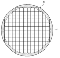
그러나 기판의 베벨부의 막 제거 및 저면 세정은 동시 또는 순차적으로 진행되며, 서로 다른 노즐에 의해 액(L) 처리된다. 도 1은 일반적인 제1노즐 및 제2노즐을 보여주는 단면도이다. 도 1을 참조하면, 제1노즐은 기판의 저면 세정을 위한 노즐이고, 제2노즐은 기판의 베벨부의 막 제거를 위한 노즐이다. 제2노즐은 제1노즐에 비해 기판의 중심축으로부터 멀리 떨어지게 위치되며, 제1노즐 및 제2노즐 각각은 그 위치가 고정된다. 따라서 베벨부의 막 제거 영역을 실시간 조절하는 것이 불가능하며, 도 2와 같이 베벨부와 인접하게 위치되는 영역의 칩은 손상된다.However, the film removal and bottom cleaning of the bevel portion of the substrate are performed simultaneously or sequentially, and liquid (L) is treated by different nozzles. 1 is a cross-sectional view showing a general first nozzle and a second nozzle. Referring to FIG. 1, a first nozzle is a nozzle for cleaning a bottom surface of a substrate, and a second nozzle is a nozzle for removing a film from a bevel portion of a substrate. The second nozzle is positioned farther away from the central axis of the substrate than the first nozzle, and the first nozzle and the second nozzle each have their positions fixed. Accordingly, it is impossible to adjust the film removal region of the bevel portion in real time, and chips in the region adjacent to the bevel portion as shown in FIG. 2 are damaged.
또한 막 제거 및 저면 세정을 위해서는 2 이상의 노즐들이 필요하며, 제1노즐과 제2노즐은 기판의 아래에서 많은 공간을 필요하는 동시에 기판에 사용된 액을 회수하는 컵과 간섭이 발생될 수 있다.In addition, two or more nozzles are required for film removal and bottom cleaning, and the first nozzle and the second nozzle require a lot of space under the substrate, and at the same time, interference with a cup for recovering liquid used for the substrate may occur.
본 발명은 기판의 베벨부와 저면 각각에 액을 공급함에 있어서, 노즐이 놓여지는 공간을 확보할 수 있는 장치 및 방법을 제공하는 것을 일 목적으로 한다.An object of the present invention is to provide an apparatus and method capable of securing a space in which a nozzle is placed in supplying a liquid to each of a bevel portion and a bottom surface of a substrate.
또한 본 발명은 기판을 액 처리하는 장치에 있어서, 장치들 간 간섭을 최소화할 수 있는 장치 및 방법을 제공하는 것을 일 목적으로 한다.Another object of the present invention is to provide an apparatus and method capable of minimizing interference between devices in an apparatus for liquid processing a substrate.
또한 본 발명은 기판의 베벨부에 인접하게 위치되는 칩이 손상되는 것을 방지할 수 있는 장치 및 방법을 제공하는 것을 일 목적으로 한다.Another object of the present invention is to provide an apparatus and method capable of preventing damage to a chip positioned adjacent to a bevel portion of a substrate.
본 발명의 실시예는 기판을 액 처리하는 장치 및 방법을 제공한다.An embodiment of the present invention provides an apparatus and method for liquid processing a substrate.
기판을 액 처리하는 장치는 내부에 처리 공간을 제공하는 처리 용기, 상기 처리 공간에서 기판을 지지하는 기판 지지 유닛, 그리고 상기 기판 지지 유닛에 지지된 기판으로 액을 공급하는 액 공급 유닛을 포함하되, 상기 기판 지지 유닛은 기판의 중심 영역이 놓이며, 기판의 가장자리 영역이 외부에 노출되도록 기판을 지지하고, 회전 가능한 지지판을 포함하며, 상기 액 공급 유닛은 상기 지지판의 아래에서 기판의 저면으로 액을 공급하는 백노즐 및 상기 백노즐로부터 토출되는 액의 토출 위치가 제1위치와 상기 제1위치보다 기판의 중심에서 멀리 떨어진 제2위치로 변경되도록 상기 백노즐을 구동시키는 구동기를 포함한다. The apparatus for liquid processing a substrate includes a processing container providing a processing space therein, a substrate support unit supporting a substrate in the processing space, and a liquid supply unit supplying a liquid to a substrate supported by the substrate support unit, The substrate support unit supports a substrate such that a central region of the substrate is placed and an edge region of the substrate is exposed to the outside, and includes a rotatable support plate, and the liquid supply unit transfers liquid from under the support plate to the bottom surface of the substrate. And a driver for driving the back nozzle so that a supply back nozzle and a discharge position of the liquid discharged from the back nozzle are changed to a first position and a second position farther from the center of the substrate than the first position.
상기 구동기를 제어하는 제어기를 더 포함하되, 상기 제어기는 상기 제2위치로 액을 토출하는 중에, 상기 구동기에 의해 상기 제2위치를 중심으로 일정 범위 내에서 토출 위치가 계속적으로 변경되도록 상기 구동기를 제어할 수 있다. Further comprising a controller for controlling the actuator, wherein the controller, while discharging the liquid to the second position, the actuator to continuously change the discharge position within a predetermined range around the second position by the actuator. Can be controlled.
상기 기판 지지 유닛은 상기 지지판을 지지하며, 회전되는 회전축과 상기 회전축을 감싸며, 상기 지지판보다 큰 직경을 가지는 지지 바디를 포함하되, 상기 백노즐은 상기 지지 바디에 설치될 수 있다. The substrate support unit supports the support plate and includes a rotating shaft that is rotated and a support body that surrounds the rotation shaft and has a larger diameter than the support plate, and the back nozzle may be installed on the support body.
상기 백노즐의 위치 변경은 상기 백노즐을 회전에 의해 이루어지도록 제공될 수 있다 상기 백노즐은 상기 구동기에 의해 회전 가능한 몸통부와 상기 몸통부에 지지되며, 액이 토출되는 토출구가 형성되는 토출부를 포함하되, 상기 토출구 및 상기 토출구에 액을 공급하는 토출 라인은 상기 몸통부의 중심축으로부터 이격되게 위치될 수 있다. 상기 토출구는 위로 갈수록 상기 중심축으로부터 멀어지거나 가까워지는 방향을 향할 수 있다. The position of the back nozzle may be changed by rotating the back nozzle. The back nozzle is supported by a rotatable body part and the body part by the actuator, and a discharge part in which a discharge port through which liquid is discharged is formed. Including, but the discharge port and the discharge line for supplying the liquid to the discharge port may be positioned to be spaced apart from the central axis of the body. The discharge port may be directed toward a direction closer to or away from the central axis as it goes upward.
상기 백노즐의 위치 변경은 상기 백노즐을 직선 이동에 의해 이루어지도록 제공될 수 있다. 상기 구동기는 길이 방향이 상부에서 바라볼 때 기판의 중심축으로부터 멀어지는 방향으로 연장되는 가이드, 상기 가이드의 길이 방향을 따라 이동 가능한 브라켓, 그리고 상기 브라켓이 이동되도록 구동력을 제공하는 모터를 포함하고, 상기 백노즐은 상기 브라켓에 설치될 수 있다. 상기 백노즐의 토출구는 기판의 중심축으로부터 멀어질수록 상향 경사진 방향을 향하도록 형성될 수 있다. The change of the position of the back nozzle may be provided so as to be made by linearly moving the back nozzle. The driver includes a guide extending in a direction away from the central axis of the substrate when the longitudinal direction is viewed from the top, a bracket movable along the longitudinal direction of the guide, and a motor providing a driving force to move the bracket, the The back nozzle may be installed on the bracket. The discharge port of the back nozzle may be formed to be inclined upward as it moves away from the central axis of the substrate.
또한 기판을 액 처리하는 장치는 내부에 처리 공간을 제공하는 처리 용기, 상기 처리 공간에서 기판을 지지하는 기판 지지 유닛, 그리고 상기 기판 지지 유닛에 지지된 기판으로 액을 공급하는 액 공급 유닛을 포함하되, 상기 기판 지지 유닛은 기판의 중심 영역이 놓이며, 기판의 가장자리 영역이 외부에 노출되도록 기판을 지지하고, 회전 가능한 지지판을 포함하며, 상기 액 공급 유닛은 상기 지지판의 아래에서 기판의 저면으로 액을 공급하는 백노즐을 포함하되, 상기 백 노즐에는 기판의 저면인 제1위치로 액을 토출하는 제1토출구와 상기 제1위치보다 기판의 중심에서 멀리 떨어진 기판의 저면인 제2위치로 액을 토출하는 제2토출구가 형성된다. In addition, the apparatus for liquid processing a substrate includes a processing container providing a processing space therein, a substrate support unit supporting the substrate in the processing space, and a liquid supply unit supplying a liquid to a substrate supported by the substrate support unit. , The substrate support unit supports the substrate so that the central region of the substrate is placed and the edge region of the substrate is exposed to the outside, and includes a rotatable support plate, and the liquid supply unit includes a liquid from below the support plate to the bottom of the substrate. It includes a back nozzle for supplying, wherein the back nozzle has a first discharge port for discharging the liquid to a first position that is a bottom surface of the substrate and a second position that is a bottom surface of the substrate further away from the center of the substrate than the first position. A second discharge port for discharging is formed.
상기 액 공급 유닛은 상기 백노즐을 회전시키는 구동기를 더 포함하되, 상기 백노즐은 상기 구동기에 의해 회전 가능한 몸통부, 상기 몸통부의 상단으로부터 수직한 방향으로 연장되며 상기 제1토출구가 형성되는 제1토출부, 상기 몸통부의 상단으로부터 상기 제1토출부와 반대되는 방향으로 연장되며 상기 제2토출구가 형성되는 제2토출부를 포함할 수 있다. The liquid supply unit further includes a driver for rotating the back nozzle, wherein the back nozzle extends in a vertical direction from an upper end of the body portion and a body rotatable by the driver, and the first discharge port is formed. It may include a discharge part, a second discharge part extending in a direction opposite to the first discharge part from an upper end of the body part and forming the second discharge port.
상기 제1토출구 및 상기 제2토출구 각각은 기판의 중심축으로부터 멀어질수록 상향 경사진 방향을 향하도록 제공될 수 있다. Each of the first discharge port and the second discharge port may be provided to face an upwardly inclined direction as the distance from the central axis of the substrate increases.
또한 기판을 액 처리하는 방법은 회전되는 상기 기판의 저면에 액을 공급하여 상기 기판을 액 처리하되, 상기 기판의 아래에 위치되는 백 노즐은 상기 액을 상기 기판의 저면인 제1위치로 토출하여 상기 기판의 저면을 액 처리하고, 상기 액을 상기 제1위치보다 상기 기판의 중심에서 멀리 떨어지며 상기 기판의 저면인 제2위치로 토출하여 상기 기판의 베벨부를 액 처리한다. In addition, the method of liquid treatment of the substrate is to liquid-process the substrate by supplying liquid to the bottom surface of the rotating substrate, and a back nozzle positioned under the substrate discharges the liquid to a first position, which is the bottom surface of the substrate. The bottom surface of the substrate is subjected to a liquid treatment, and the liquid is discharged to a second position, which is a lower surface of the substrate, farther from the center of the substrate than the first position, thereby processing the bevel portion of the substrate.
상기 액은 상기 제1위치로 토출된 후에 상기 제2위치로 토출될 수 있다. 상기 제1위치로 상기 액을 토출하는 것과 상기 제2위치로 상기 액을 토출하는 것 간의 변경은 상기 백 노즐을 회전 이동시킴으로써 이루어질 수 있다. The liquid may be discharged to the first position and then discharged to the second position. A change between discharging the liquid to the first position and discharging the liquid to the second position can be made by rotating the bag nozzle.
상기 제1위치에서 상기 기판을 액 처리하는 것은 상기 기판의 저면을 세정하는 세정 처리이고, 상기 제2위치에서 상기 기판을 액 처리하는 것은 상기 기판의 상면의 베벨부 영역에서 막질을 제거하는 제거 처리일 수 있다. 상기 제2위치로 상기 액을 토출하는 중에는 상기 제2위치를 중심으로 일정 범위 내에서 토출 위치가 계속적으로 변경될 수 있다. Liquid-treating the substrate at the first position is a cleaning treatment for cleaning the bottom of the substrate, and liquid-treating the substrate at the second position is a removal treatment for removing film quality from the bevel portion of the upper surface of the substrate Can be While discharging the liquid to the second position, the discharging position may be continuously changed within a predetermined range around the second position.
상기 기판의 상면에는 복수의 칩에 제공되며, 상기 제2위치를 중심으로 일정 범위 내에서 계속적으로 변경되는 토출되는 상기 칩에 액이 제공되지 않도록 하는 토출 위치일 수 있다. The upper surface of the substrate may be a discharge position that is provided to a plurality of chips and prevents liquid from being provided to the discharged chip that is continuously changed within a predetermined range around the second position.
상기 세정 처리 및 상기 제거 처리는 상기 기판에 포토레지스트를 공급하는 처리 이후에 이루어지고, 상기 제거 처리에서 제거되는 막질은 포토레지스트 막일 수 있다. The cleaning treatment and the removal treatment are performed after a treatment of supplying a photoresist to the substrate, and a film quality removed in the removal treatment may be a photoresist film.
본 발명의 실시예에 의하면, 기판의 베벨부 및 저면 각각은 단일의 노즐에 의해 세정된다. 이로 인해 노즐이 배치되는 공간 확보가 용이하다.According to an embodiment of the present invention, each of the bevel portion and the bottom surface of the substrate is cleaned by a single nozzle. This makes it easy to secure a space in which the nozzles are arranged.
또한 본 발명의 실시예에 의하면, 노즐은 구동기에 의해 토출 위치가 변경된다. 이에 따라 기판의 베벨부에 공급되는 영역을 조절 가능하며, 베벨부에 인접하게 배치된 칩 손상을 방지할 수 있다.In addition, according to the embodiment of the present invention, the ejection position of the nozzle is changed by the actuator. Accordingly, an area supplied to the bevel portion of the substrate can be adjusted, and damage to chips disposed adjacent to the bevel portion can be prevented.
도 1은 일반적인 제1노즐 및 제2노즐을 보여주는 단면도이다.
도 2는 도 1의 제2노즐에 의해 기판의 상면에 액이 공급되는 영역을 보여주는 평면도이다.
도 3은 본 발명의 일 실시 예에 따른 기판 처리 장치를 개략적으로 보여주는 사시도이다.
도 4는 도 3의 도포 블럭 또는 현상 블럭을 보여주는 기판 처리 장치의 단면도이다.
도 5는 도 3의 기판 처리 장치의 평면도이다.
도 6은 도 5의 반송 로봇의 핸드의 일 예를 보여주는 도면이다.
도 7은 도 5의 열처리 챔버의 일 예를 개략적으로 보여주는 평면도이다.
도 8은 도 7의 열처리 챔버의 정면도이다.
도 9는 도 5의 액 처리 챔버의 일 예를 개략적으로 보여주는 도면이다.
도 10은 도 9의 백노즐의 제1실시예를 보여주는 사시도이다.
도 11 내지 도 13은 도 8의 백노즐을 구동되는 과정을 보여주는 단면도들이다.
도 14는 도 12 및 도 13의 백노즐에서 공급되는 액의 토출 위치 보여주는 평면도이다.
도 15는 도 10의 제2실시예의 백 노즐의 구동 과정을 보여주는 단면도이다.
도 16은 도 10의 제3실시예의 백 노즐의 구동 과정을 보여주는 단면도이다.1 is a cross-sectional view showing a general first nozzle and a second nozzle.
FIG. 2 is a plan view illustrating a region where a liquid is supplied to an upper surface of a substrate by the second nozzle of FIG. 1.
3 is a schematic perspective view of a substrate processing apparatus according to an embodiment of the present invention.
4 is a cross-sectional view of a substrate processing apparatus showing the coating block or the developing block of FIG. 3.
5 is a plan view of the substrate processing apparatus of FIG. 3.
6 is a diagram illustrating an example of a hand of the transfer robot of FIG. 5.
7 is a plan view schematically showing an example of the heat treatment chamber of FIG. 5.
8 is a front view of the heat treatment chamber of FIG. 7.
9 is a diagram schematically showing an example of the liquid processing chamber of FIG. 5.
10 is a perspective view showing a first embodiment of the back nozzle of FIG. 9.
11 to 13 are cross-sectional views illustrating a process of driving the back nozzle of FIG. 8.
14 is a plan view showing a discharge position of a liquid supplied from the back nozzle of FIGS. 12 and 13;
15 is a cross-sectional view showing a driving process of the bag nozzle of the second embodiment of FIG. 10.
16 is a cross-sectional view showing a driving process of the bag nozzle of the third embodiment of FIG. 10.
이하, 본 발명의 실시 예를 첨부된 도면들을 참조하여 더욱 상세하게 설명한다. 본 발명의 실시 예는 여러 가지 형태로 변형할 수 있으며, 본 발명의 범위가 아래의 실시 예들로 한정되는 것으로 해석되어서는 안 된다. 본 실시 예는 당 업계에서 평균적인 지식을 가진 자에게 본 발명을 더욱 완전하게 설명하기 위해 제공되는 것이다. 따라서 도면에서의 요소의 형상은 보다 명확한 설명을 강조하기 위해 과장된 것이다.Hereinafter, embodiments of the present invention will be described in more detail with reference to the accompanying drawings. The embodiments of the present invention may be modified in various forms, and the scope of the present invention should not be construed as being limited to the following embodiments. This embodiment is provided to more completely explain the present invention to those with average knowledge in the industry. Therefore, the shape of the element in the drawings is exaggerated to emphasize a more clear description.
도 3은 본 발명의 일 실시 예에 따른 기판 처리 장치를 개략적으로 보여주는 사시도이고, 도 4는 도 3의 도포 블럭 또는 현상 블럭을 보여주는 기판 처리 장치의 단면도이며, 도 5는 도 3의 기판 처리 장치의 평면도이다.3 is a perspective view schematically showing a substrate processing apparatus according to an embodiment of the present invention, FIG. 4 is a cross-sectional view of the substrate processing apparatus showing a coating block or a developing block of FIG. 3, and FIG. 5 is a substrate processing apparatus of FIG. It is a top view.
도 3 내지 도 5를 참조하면, 기판 처리 장치(1)는 인덱스 모듈(20,index module), 처리 모듈(30, treating module), 그리고 인터페이스 모듈(40, interface module)을 포함한다. 일 실시예에 의하며, 인덱스 모듈(20), 처리 모듈(30), 그리고 인터페이스 모듈(40)은 순차적으로 일렬로 배치된다. 이하, 인덱스 모듈(20), 처리 모듈(30), 그리고 인터페이스 모듈(40)이 배열된 방향을 제1 방향(12)이라 하고, 상부에서 바라볼 때 제1 방향(12)과 수직한 방향을 제2 방향(14)이라 하고, 제1 방향(12) 및 제2 방향(14)에 모두 수직한 방향을 제3 방향(16)이라 한다.3 to 5, the
인덱스 모듈(20)은 기판(W)이 수납된 용기(10)로부터 기판(W)을 처리 모듈(30)로 반송하고, 처리가 완료된 기판(W)을 용기(10)로 수납한다. 인덱스 모듈(20)의 길이 방향은 제2 방향(14)으로 제공된다. 인덱스 모듈(20)은 로드포트(22)와 인덱스 프레임(24)을 가진다. 인덱스 프레임(24)을 기준으로 로드포트(22)는 처리 모듈(30)의 반대 측에 위치된다. 기판(W)들이 수납된 용기(10)는 로드포트(22)에 놓인다. 로드포트(22)는 복수 개가 제공될 수 있으며, 복수의 로드포트(22)는 제2 방향(14)을 따라 배치될 수 있다. The
용기(10)로는 전면 개방 일체 식 포드(Front Open Unified Pod:FOUP)와 같은 밀폐용 용기(10)가 사용될 수 있다. 용기(10)는 오버헤드 트랜스퍼(Overhead Transfer), 오버헤드 컨베이어(Overhead Conveyor), 또는 자동 안내 차량(Automatic Guided Vehicle)과 같은 이송 수단(도시되지 않음)이나 작업자에 의해 로드포트(22)에 놓일 수 있다. As the
인덱스 프레임(24)의 내부에는 인덱스 로봇(2200)이 제공된다. 인덱스 프레임(24) 내에는 길이 방향이 제2 방향(14)으로 제공된 가이드 레일(2300)이 제공되고, 인덱스 로봇(2200)은 가이드 레일(2300) 상에서 이동 가능하게 제공될 수 있다. 인덱스 로봇(2200)은 기판(W)이 놓이는 핸드(2220)를 포함하며, 핸드(2220)는 전진 및 후진 이동, 제3 방향(16)을 축으로 한 회전, 그리고 제3 방향(16)을 따라 이동 가능하게 제공될 수 있다. An
처리 모듈(30)은 기판(W)에 대해 도포 공정 및 현상 공정을 수행한다. 처리 모듈(30)은 도포 블럭(30a) 및 현상 블럭(30b)을 가진다. 도포 블럭(30a)은 기판(W)에 대해 도포 공정을 수행하고, 현상 블럭(30b)은 기판(W)에 대해 현상 공정을 수행한다. 도포 블럭(30a)은 복수 개가 제공되며, 이들은 서로 적층되게 제공된다. 현상 블럭(30b)은 복수 개가 제공되며, 현상 블럭들(30b)은 서로 적층되게 제공된다. 도 3의 실시예에 의하면, 도포 블럭(30a)은 2개가 제공되고, 현상 블럭(30b)은 2개가 제공된다. 도포 블럭들(30a)은 현상 블럭들(30b)의 아래에 배치될 수 있다. 일 예에 의하면, 2개의 도포 블럭들(30a)은 서로 동일한 공정을 수행하며, 서로 동일한 구조로 제공될 수 있다. 또한, 2개의 현상 블럭들(30b)은 서로 동일한 공정을 수행하며, 서로 동일한 구조로 제공될 수 있다.The
도 5를 참조하면, 도포 블럭(30a)은 열처리 챔버(3200), 반송 챔버(3400), 액 처리 챔버(3600), 그리고 버퍼 챔버(3800)를 가진다. 열처리 챔버(3200)는 기판(W)에 대해 열처리 공정을 수행한다. 열처리 공정은 냉각 공정 및 가열 공정을 포함할 수 있다. 액처리 챔버(3600)는 기판(W) 상에 액을 공급하여 액막을 형성한다. 액막은 포토레지스트막 또는 반사방지막일 수 있다. 반송 챔버(3400)는 도포 블럭(30a) 내에서 열처리 챔버(3200)와 액처리 챔버(3600) 간에 기판(W)을 반송한다. Referring to FIG. 5, the
반송 챔버(3400)는 그 길이 방향이 제1 방향(12)과 평행하게 제공된다. 반송 챔버(3400)에는 반송 로봇(3422)이 제공된다. 반송 로봇(3422)은 열처리 챔버(3200), 액처리 챔버(3600), 그리고 버퍼 챔버(3800) 간에 기판을 반송한다. 일 예에 의하면, 반송 로봇(3422)은 기판(W)이 놓이는 핸드(3420)를 가지며, 핸드(3420)는 전진 및 후진 이동, 제3 방향(16)을 축으로 한 회전, 그리고 제3 방향(16)을 따라 이동 가능하게 제공될 수 있다. 반송 챔버(3400) 내에는 그 길이 방향이 제1 방향(12)과 평행하게 제공되는 가이드 레일(3300)이 제공되고, 반송 로봇(3422)은 가이드 레일(3300) 상에서 이동 가능하게 제공될 수 있다. The conveying
도 6은 도 5의 반송 로봇의 핸드의 일 예를 보여주는 도면이다. 도 6을 참조하면, 핸드(3420)는 베이스(3428) 및 지지 돌기(3429)를 가진다. 베이스(3428)는 원주의 일부가 절곡된 환형의 링 형상을 가질 수 있다. 베이스(3428)는 기판(W)의 직경보다 큰 내경을 가진다. 지지 돌기(3429)는 베이스(3428)로부터 그 내측으로 연장된다. 지지 돌기(3429)는 복수 개가 제공되며, 기판(W)의 가장자리 영역을 지지한다. 일 예에 의하며, 지지 돌기(3429)는 등 간격으로 4개가 제공될 수 있다. 6 is a diagram illustrating an example of a hand of the transfer robot of FIG. 5. 6, the
열처리 챔버(3200)는 복수 개로 제공된다. 도 4와 도 5를 참조하면, 열처리 챔버들(3200)은 제1방향(12)을 따라 나열되게 배치된다. 열처리 챔버들(3200)은 반송 챔버(3400)의 일측에 위치된다.The heat treatment chamber 3200 is provided in plural. 4 and 5, the heat treatment chambers 3200 are arranged to be arranged along the
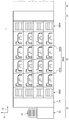
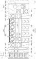
도 7은 도 5의 열처리 챔버의 일 예를 개략적으로 보여주는 평면도이고, 도 8은 도 7의 열처리 챔버의 정면도이다. 열처리 챔버(3200)는 하우징(3210), 냉각 유닛(3220), 가열 유닛(3230), 그리고 반송 플레이트(3240)를 가진다. 7 is a plan view schematically showing an example of the heat treatment chamber of FIG. 5, and FIG. 8 is a front view of the heat treatment chamber of FIG. 7. The heat treatment chamber 3200 has a
하우징(3210)은 대체로 직육면체의 형상으로 제공된다. 하우징(3210)의 측벽에는 기판(W)이 출입되는 반입구(도시되지 않음)가 형성된다. 반입구는 개방된 상태로 유지될 수 있다. 선택적으로 반입구를 개폐하도록 도어(도시되지 않음)가 제공될 수 있다. 냉각 유닛(3220), 가열 유닛(3230), 그리고 반송 플레이트(3240)는 하우징(3210) 내에 제공된다. 냉각 유닛(3220) 및 가열 유닛(3230)은 제2 방향(14)을 따라 나란히 제공된다. 일 예에 의하면, 냉각 유닛(3220)은 가열 유닛(3230)에 비해 반송 챔버(3400)에 더 가깝게 위치될 수 있다.The
냉각 유닛(3220)은 냉각판(3222)을 가진다. 냉각판(3222)은 상부에서 바라볼 때 대체로 원형의 형상을 가질 수 있다. 냉각판(3222)에는 냉각부재(3224)가 제공된다. 일 예에 의하면, 냉각부재(3224)는 냉각판(3222)의 내부에 형성되며, 냉각 유체가 흐르는 유로로 제공될 수 있다. The
가열 유닛(3230)은 가열판(3232), 커버(3234), 그리고 히터(3233)를 가진다. 가열판(3232)은 상부에서 바라볼 때 대체로 원형의 형상을 가진다. 가열판(3232)은 기판(W)보다 큰 직경을 가진다. 가열판(3232)에는 히터(3233)가 설치된다. 히터(3233)는 전류가 인가되는 발열저항체로 제공될 수 있다. 가열판(3232)에는 제3 방향(16)을 따라 상하 방향으로 구동 가능한 리프트 핀(3238)들이 제공된다. 리프트 핀(3238)은 가열 유닛(3230) 외부의 반송 수단으로부터 기판(W)을 인수받아 가열판(3232) 상에 내려놓거나 가열판(3232)으로부터 기판(W)을 들어올려 가열 유닛(3230) 외부의 반송 수단으로 인계한다. 일 예에 의하면, 리프트 핀(3238)은 3개가 제공될 수 있다. 커버(3234)는 내부에 하부가 개방된 공간을 가진다.7 커버(3234)는 가열판(3232)의 상부에 위치되며 구동기(3236)에 의해 상하 방향으로 이동된다. 커버(3234)가 가열판(3232)에 접촉되면, 커버(3234)와 가열판(3232)에 의해 둘러싸인 공간은 기판(W)을 가열하는 가열 공간으로 제공된다. The
반송 플레이트(3240)는 대체로 원판 형상을 제공되고, 기판(W)과 대응되는 직경을 가진다. 반송 플레이트(3240)의 가장자리에는 노치(3244)가 형성된다. 노치(3244)는 상술한 반송 로봇(3422, 3424)의 핸드(3420)에 형성된 돌기(3429)와 대응되는 형상을 가질 수 있다. 또한, 노치(3244)는 핸드(3420)에 형성된 돌기(3429)와 대응되는 수로 제공되고, 돌기(3429)와 대응되는 위치에 형성된다. 핸드(3420)와 반송 플레이트(3240)가 상하 방향으로 정렬된 위치에서 핸드(3420)와 반송 플레이트(3240)의 상하 위치가 변경하면 핸드(3420)와 반송 플레이트(3240) 간에 기판(W)의 전달이 이루어진다. 반송 플레이트(3240)는 가이드 레일(3249) 상에 장착되고, 구동기(3246)에 의해 가이드 레일(3249)을 따라 제1영역(3212)과 제2영역(3214) 간에 이동될 수 있다. 반송 플레이트(3240)에는 슬릿 형상의 가이드 홈(3242)이 복수 개 제공된다. 가이드 홈(3242)은 반송 플레이트(3240)의 끝단에서 반송 플레이트(3240)의 내부까지 연장된다. 가이드 홈(3242)은 그 길이 방향이 제2 방향(14)을 따라 제공되고, 가이드 홈(3242)들은 제1 방향(12)을 따라 서로 이격되게 위치된다. 가이드 홈(3242)은 반송 플레이트(3240)와 가열 유닛(3230) 간에 기판(W)의 인수인계가 이루어질 때 반송 플레이트(3240)와 리프트 핀(1340)이 서로 간섭되는 것을 방지한다. The
기판(W)의 가열은 기판(W)이 지지 플레이트(1320) 상에 직접 놓인 상태에서 이루어지고, 기판(W)의 냉각은 기판(W)이 놓인 반송 플레이트(3240)가 냉각판(3222)에 접촉된 상태에서 이루어진다. 냉각판(3222)과 기판(W) 간에 열전달이 잘 이루어지도록 반송 플레이트(3240)은 열전달율이 높은 재질로 제공된다. 일 예에 의하면, 반송 플레이트(3240)은 금속 재질로 제공될 수 있다. The substrate W is heated while the substrate W is directly placed on the support plate 1320, and the substrate W is cooled by the
열처리 챔버들(3200) 중 일부의 열처리 챔버에 제공된 가열 유닛(3230)은 기판(W) 가열 중에 가스를 공급하여 포토레지스트의 기판(W) 부착률을 향상시킬 수 있다. 일 예에 의하면, 가스는 헥사메틸디실란(hexamethyldisilane) 가스일 수 있다. The
액처리 챔버(3600)는 복수 개로 제공된다. 액처리 챔버들(3600) 중 일부는 서로 적층되도록 제공될 수 있다. 도 4 및 도 5를 참조하면, 액 처리 챔버들(3600)은 반송 챔버(3402)의 일측에 배치된다. 액 처리 챔버들(3600)은 제1방향(12)을 따라 나란히 배열된다. 액 처리 챔버들(3600) 중 일부는 인덱스 모듈(20)과 인접한 위치에 제공된다. 이하, 이들 액처리 챔버를 전단 액처리 챔버(3602)(front liquid treating chamber)라 칭한다. 액 처리 챔버들(3600)은 중 다른 일부는 인터페이스 모듈(40)과 인접한 위치에 제공된다. 이하, 이들 액처리 챔버를 후단 액처리 챔버(3604)(rear heat treating chamber)라 칭한다. The
전단 액처리 챔버(3602)는 기판(W)상에 제1액을 도포하고, 후단 액처리 챔버(3604)는 기판(W) 상에 제2액을 도포한다. 제1액과 제2액은 서로 상이한 종류의 액일 수 있다. 일 실시예에 의하면, 제1액은 반사 방지막이고, 제2액은 포토레지스트이다. 포토레지스트는 반사 방지막이 도포된 기판(W) 상에 도포될 수 있다. 선택적으로 제1액은 포토레지스트이고, 제2액은 반사방지막일 수 있다. 이 경우, 반사방지막은 포토레지스트가 도포된 기판(W) 상에 도포될 수 있다. 선택적으로 제1액과 제2액은 동일한 종류의 액이고, 이들은 모두 포토레지스트일 수 있다.The front-end
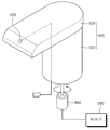
액 처리 챔버(3602, 3604)은 모두 동일한 구조를 가지며, 전단 액처리 챔버(3602)를 일 예로 설명한다. 도 9는 도 5의 액 처리 챔버의 일 예를 보여주는 단면도이다. 도 9를 참조하면, 전단 액처리 챔버(3602)는 기판 상에 액막을 형성하는 장치(800)로 제공된다. 전단 액처리 챔버(3602,800)는 하우징(810), 기류 제공 유닛(820), 기판 지지 유닛(830), 처리 용기(850), 승강 유닛(890), 액 공급 유닛(840), 그리고 제어기를 포함한다. Both the
하우징(810)은 내부에 공간(812)을 가지는 직사각의 통 형상으로 제공된다. 하우징(810)의 일측에는 개구(미도시)가 형성된다. 개구는 기판(W)이 반출입되는 입구로 기능한다. 개구에는 도어가 설치되며, 도어는 개구를 개폐한다. 도어는 기판 처리 공정이 진행되면, 개구를 차단하여 하우징(810)의 내부 공간(812)을 밀폐한다. 하우징(810)의 하부면에는 내측 배기구(814) 및 외측 배기구(816)가 형성된다. 하우징(810) 내에 형성된 기류는 내측 배기구(814) 및 외측 배기구(816)를 통해 외부로 배기된다. 일 예에 의하면, 처리 용기(850) 내에 제공된 기류는 내측 배기구(814)를 통해 배기되고, 처리 용기(850)의 외측에 제공된 기류는 외측 배기구(816)를 통해 배기될 수 있다.The
기류 제공 유닛(820)은 하우징(810)의 내부 공간에 하강 기류를 형성한다. 기류 제공 유닛(820)은 기류 공급 라인(822), 팬(824), 그리고 필터(826)를 포함한다. 기류 공급 라인(822)은 하우징(810)에 연결된다. 기류 공급 라인(822)은 외부의 에어를 하우징(810)에 공급한다. 필터(826)는 기류 공급 라인(822)으로부터 제공되는 에어를 필터(826)링 한다. 필터(826)는 에어에 포함된 불순물을 제거한다. 팬(824)은 하우징(810)의 상부면에 설치된다. 팬(824)은 하우징(810)의 상부면에서 중앙 영역에 위치된다. 팬(824)은 하우징(810)의 내부 공간에 하강 기류를 형성한다. 기류 공급 라인(822)으로부터 팬(824)에 에어가 공급되면, 팬(824)은 아래 방향으로 에어를 공급한다.The
기판 지지 유닛(830)은 하우징(810)의 내부 공간에서 기판(W)을 지지한다. 기판 지지 유닛(830)은 기판(W)을 회전시킨다. 기판 지지 유닛(830)은 지지판(832), 회전축(834), 지지 바디(836), 그리고 구동기(836)를 포함한다. 지지판(832)은 기판을 지지하며, 회전 가능한 스핀척(832)으로 제공된다. 스핀척(832)은 원형의 판 형상을 가지도록 제공된다. 스핀척(832)의 상면에는 기판(W)이 접촉한다. 스핀척(832)은 기판(W)보다 작은 직경을 가지도록 제공된다. 일 예에 의하면, 스핀척(832)은 기판(W)을 진공 흡입하여 기판(W)을 척킹할 수 있다. 선택적으로, 스핀척(832)은 정전기를 이용하여 기판(W)을 척킹하는 정전척으로 제공될 수 있다. 또한 스핀척(832)은 기판(W)을 물리적 힘으로 척킹할 수 있다. The
회전축(834) 및 구동기(미도시)는 스핀척(832)을 회전시키는 회전 구동 부재로 제공된다. 회전축(834)은 스핀척(832)의 아래에서 스핀척(832)을 지지한다. 회전축(834)은 그 길이방향이 상하방향을 향하도록 제공된다. 회전축(834)은 그 중심축을 중심으로 회전 가능하도록 제공된다. 구동기(미도시)는 회전축(834)이 회전되도록 구동력을 제공한다. 예컨대, 구동기(미도시)는 회전축(834)의 회전 속도를 가변 가능한 모터일 수 있다.The
지지 바디(836)는 회전축(834)을 감싸는 원통 형상으로 제공된다. 지지 바디(836)는 회전축(834)에 액이 침투되어 오염되는 것을 방지한다. 이와 동시에 지지 바디(836)는 백노즐(920)을 지지한다. 지지 바디(836)는 스핀척(832)에 비해 큰 직경을 가진다. 지지 바디(836)는 스핀척(832)에 놓인 기판의 가장자리 영역과 마주하게 위치될 수 있다.The
처리 용기(850)는 하우징(810)의 내부 공간(812)에 위치된다. 처리 용기(850)는 내부에 처리 공간을 제공한다. 처리 용기(850)는 상부가 개방된 컵 형상을 가지도록 제공된다. 처리 용기(850)는 내측 컵(852) 및 외측 컵(862)을 포함한다. The
내측 컵(852)은 회전축(834)을 감싸는 원형의 판 형상으로 제공된다. 상부에서 바라볼 때 내측 컵(852)은 내측 배기구(814)와 중첩되도록 위치된다. 상부에서 바라볼 때 내측 컵(852)의 상면은 그 외측 영역과 내측 영역 각각이 서로 상이한 각도로 경사지도록 제공된다. 일 예에 의하면, 내측 컵(852)의 외측 영역은 기판 지지 유닛(830)으로부터 멀어질수록 하향 경사진 방향을 향하며, 내측 영역은 기판 지지 유닛(830)에 가까워질수록 하향 경사진 방향을 향하도록 제공되고, 이후에 수평 방향으로 연장되게 제공된다. 내측 컵(852)의 외측 영역과 내측 영역이 서로 만나는 지점은 기판(W)의 측단부와 상하 방향으로 대응되게 제공된다. 내측 컵(852)의 상면 외측 영역은 처리액이 흐르는 영역으로 제공될 수 있다. 내측 컵(852)의 상면 내측 영역에서 수평 방향으로 연장되는 영역은 세정 노즐이 설치되는 위치로 제공될 수 있다.The
외측 컵(862)은 기판 지지 유닛(830) 및 내측 컵(852)을 감싸는 컵 형상을 가지도록 제공된다. 외측 컵(862)은 바닥벽(864), 측벽(866), 상벽(870), 그리고 경사벽(870)을 가진다. 바닥벽(864)은 중공을 가지는 원형의 판 형상을 가지도록 제공된다. 바닥벽(864)에는 회수 라인(865)이 형성된다. 회수 라인(865)은 기판(W) 상에 공급된 처리액을 회수한다. 회수 라인(865)에 의해 회수된 처리액은 외부의 액 재생 시스템에 의해 재사용될 수 있다. 측벽(866)은 기판 지지 유닛(830)을 감싸는 원형의 통 형상을 가지도록 제공된다. 측벽(866)은 바닥벽(864)의 측단으로부터 수직한 방향으로 연장된다. 측벽(866)은 바닥벽(864)으로부터 위로 연장된다. The
경사벽(870)은 측벽(866)의 상단으로부터 외측 컵(862)의 내측 방향으로 연장된다. 경사벽(870)은 위로 갈수록 기판 지지 유닛(830)에 가까워지도록 제공된다. 경사벽(870)은 링 형상을 가지도록 제공된다. 경사벽(870)의 상단은 기판 지지 유닛(830)에 지지된 기판(W)보다 높게 위치된다. The
승강 유닛(890)은 내측 컵(852) 및 외측 컵(862)을 각각 승강 이동시킨다. 승강 유닛(890)은 내측 이동 부재(892) 및 외측 이동 부재(894)를 포함한다. 내측 이동 부재(892)는 내측 컵(852)을 승강 이동 시키고, 외측 이동 부재(894)는 외측 컵(862)을 승강 이동시킨다. The lifting unit 890 lifts and moves the
액 공급 유닛(840)은 기판(W) 상에 처리액, 프리 웨트액, 제거액, 그리고 세정액을 공급한다. 액 공급 유닛(840)은 프리 웨트 노즐(842), 감광액 노즐(844), 백노즐(920), 그리고 구동기(940)를 포함한다. The liquid supply unit 840 supplies a processing liquid, a pre-wet liquid, a removal liquid, and a cleaning liquid onto the substrate W. The liquid supply unit 840 includes a free
프리 웨트 노즐(842) 및 감광액 노즐(844)은 아암(848)에 의해 함께 지지되어 함께 이동된다. 아암(848)은 수평 방향으로 이동되어 프리 웨트 노즐(842) 및 감광액 노즐(844)을 공정 위치와 대기 위치로 이동시킬 수 있다. 여기서 공정 위치는 프리 웨트 노즐(842) 및 감광액 노즐(844)이 기판(W)과 마주하는 위치이고, 대기 위치는 공정 위치를 벗어난 위치일 수 있다. 예컨대, 프리 웨트 노즐(842) 및 감광액 노즐(844)은 제1방향(12)과 평행한 방향으로 이동될 수 있다.The free
프리 웨트 노즐(842)은 기판(W) 상에 프리 웨트액을 공급하고, 감광액 노즐(844)은 기판(W) 상에 처리액을 공급한다. 예컨대, 프리 웨트액은 기판(W)의 표면을 처리액과 유사 또는 동일한 성질을 변화시킬 수 있는 액일 수 있다. 프리 웨트액은 기판(W)의 표면을 젖음 상태로 변화시킬 수 있다. 처리액은 포토 레지스트와 같은 감광액일 수 있다. 감광액 노즐(844)은 복수 개로 제공된다. 감광액 노즐(844)은 프리 웨트 노즐(842)을 사이에 두고 양측에 일렬로 배열되게 위치된다. 각각의 감광액 노즐(844)은 서로 다른 종류의 처리액을 토출할 수 있다. 각각의 처리 노즐들(844)은 서로 독립된 라인으로부터 처리액을 공급받는다. The
프리 웨트 노즐(842) 및 감광액 노즐(844) 각각은 기판(W)의 중앙 위치에 프리 웨트액 및 처리액을 공급한다. 프리 웨트 노즐(842) 및 감광액 노즐(844) 각각은 그 토출구(926)가 수직한 아래방향을 향하도록 제공된다. Each of the
백노즐(920)은 기판(W)의 저면 및 베벨부를 액 처리한다. 여기서 백노즐(920)에 의해 액 처리되는 저면은 기판(W)의 저면에서 스핀척(832)이 놓여지지 않는 영역을 포함한다. 또한 백노즐(920)에 의해 액 처리되는 베벨부는 기판(W)의 상면 끝단 및 저면 끝단 각각을 가지는 측부를 포함한다. 따라서 백노즐(920)은 기판(W)의 베벨부에 형성된 감광액막을 제거한다. 백노즐(920)은 복수 개로 제공되며, 서로 간에 일정 간격을 두고 이격되게 위치된다. 본 실시예에는 백노즐(920)이 2 개로 제공되며, 회전축을 사이에 두고 서로 마주하게 위치되는 것으로 설명한다. 백노즐(920)은 지지 바디(836)에 설치되며, 스핀척(832)에 놓여진 기판(W)과 상하로 마주하게 위치된다. 백노즐(920)은 구동기(940)에 의해 회전 이동하며 액의 토출 위치가 변경된다. 여기서 회전 이동은 백노즐(920)의 중심축을 중심으로 회전되는 이동과 상하 방향의 임의축을 중심으로 회전되는 스윙 이동을 포함한다. 구동기(940)는 모터일 수 있다. 본 실시예에는 백노즐(920)이 중심축을 중심으로 회전 이동되는 것으로 설명한다. The
백노즐(920)은 몸통부(922) 및 토출부(924)를 포함한다. 도 10은 도 9의 백노즐의 제1실시예를 보여주는 사시도이다. 도 10을 참조하면, 몸통부(922)는 지지 바디(836)의 상면에 설치된다. 상부에서 바라볼 때 몸통부(922)는 스핀척(832)에 놓인 기판(W)의 측단보다 내측에 위치된다. 몸통부(922)는 길이 방향이 상하로 제공되는 통 형상을 가진다. 토출부(924)는 몸통부(922)에 의해 지지된다. 토출부(924)는 몸통부(922)의 상단으로부터 몸통부(922)의 길이 방향과 상이한 방향으로 연장되게 제공된다. 일 예에 의하면, 토출부(924)는 몸통부(922)로부터 수직한 방향으로 연장되게 제공될 수 있다. 토출부(924)에는 상면 또는 측면에 기판(W)을 향하도록 제공되는 토출구(926)가 형성된다. 예컨대, 토출구(926) 및 토출구(926)에 액을 공급하며, 토출부(924)의 내부에 형성된 토출 라인은 몸통부(922)의 중심축으로부터 이격되게 위치될 수 있다. 토출구(926)는 위로 갈수록 기판(W)의 중심축에서 멀어지거나 가까워지는 방향을 향하도록 제공된다. 토출구(926)가 향하는 방향은 몸통부(922)의 회전에 의해 이루어진다. 백노즐(920)은 제1위치와 제2위치에 액을 토출하며, 이는 몸통부(922)의 회전에 의해 이루어진다. 제1위치는 기판(W)의 저면을 포함하고, 제2위치는 기판(W)의 저면에서 제1위치보다 기판(W)의 중심축으로부터 멀리 떨어진 위치이다. 백노즐(920)은 토출구(926)가 위로 갈수록 기판(W)의 중심축에 가까워지는 상향 경사진 방향으로 액을 토출하여 제1위치에 액을 공급한다. 백노즐(920)은 토출구(926)가 위로 갈수록 기판(W)의 중심축에 멀어지는 상향 경사진 방향으로 액을 토출하여 제2위치에 액을 공급한다. 제2위치에 공급된 액은 일부가 기판(W)의 표면을 타고 기판(W)의 상면까지 공급된다. 이에 따라 제2위치에 액을 공급하여 기판(W)의 베벨부를 액 처리할 수 있다. 예컨대, 백노즐(920)로부터 토출되는 액은 감광액을 희석시키는 액일 수 있다. 희석액은 신나(Thinner)일 수 있다.The
제어기(990)는 액의 토출 위치를 계속적으로 변경되도록 구동기(940)를 제어한다. 제어기(990)는 제2위치에 액을 공급되는 중에 토출 위치가 계속적으로 변경되도록 구동기(940)를 제어할 수 있다. 제어기(990)는 기판(W)의 상면에 형성된 칩에 액이 공급되지 않도록 토출 위치를 계속적으로 변경할 수 있다. The
다음은 상술한 기판 처리 장치를 이용하여 기판(W) 상에 액막을 형성 및 제거하는 방법을 설명한다.Next, a method of forming and removing a liquid film on the substrate W using the substrate processing apparatus described above will be described.
기판(W)이 지지판(832)에 놓여지면, 지지판(832)은 회전되어 기판(W)을 회전시킨다. 감광액 노즐은 기판(W)의 상면 중심으로 감광액을 공급하여 기판(W)의 상면 전체 영역에 감광액막을 형성한다. 감광액막이 형성되면, 기판(W) 세정 및 막 제거 공정이 진행된다. 여기서 기판(W)의 세정 처리 및 막 제거 처리 공정은 순차적으로 진행된다. When the substrate W is placed on the
도 11 내지 도 13은 도 8의 백노즐이 기판에 액을 공급하는 과정을 보여주는 단면도들이고, 도 14는 도 12 및 도 13의 백노즐에서 공급되는 액의 토출 위치 보여주는 평면도이다. 도 11 내지 도 14를 참조하면, 백노즐(920)은 제1위치에 액을 공급한다. 제1위치에 공급된 액(L)은 기판(W)의 저면 잔류물을 제거한다. 제1위치에 공급된 액(L)은 기판(W) 상에 감광액막이 형성되는 중에 비산되어 부착된 감광액을 세정한다. 제1위치의 액(L) 토출에 의해 기판(W) 세정 처리가 완료되면, 기판(W)의 막 제거 공정이 수행된다. 막 제거 공정이 진행되면, 토출구(926)가 제2위치를 향하도록 백노즐(920)이 회전된다. 백노즐(920)은 액(L)을 토출하는 중에 회전될 수 있다. 백노즐(920)은 제2위치에 액(L)을 공급하는 중에 계속적으로 토출 위치를 변경할 수 있다. 여기서 토출 위치의 변경은 기판(W)의 상면에 액(L)이 공급되는 영역을 조절하기 위함이다. 백노즐(920)은 기판(W)의 상면에 액(L) 공급영역을 조절하여 기판(W) 상에 제공된 칩에 액(L)이 접촉되는 것을 방지한다. 따라서 칩 및 칩 상에 형성된 감광액막에는 액(L)이 미접촉되는 반면, 칩이 제공되는 않은 영역에는 감광액이 제거된다. 11 to 13 are cross-sectional views showing a process in which the back nozzle of FIG. 8 supplies liquid to the substrate, and FIG. 14 is a plan view showing a discharge position of the liquid supplied from the back nozzle of FIGS. 12 and 13. 11 to 14, the
상술한 실시예에는 백노즐(920)의 토출 위치 변경이 백노즐(920)의 회전에 의해 이루어지는 것으로 설명하였다. 그러나 백노즐(920)의 제2실시예에 따르면 도 15와 같이, 백노즐(920)의 토출 위치 변경은 직선 이동에 의해 이루어질 수 있다. 백노즐(920)의 토출구(926)는 위로 갈수록 기판(W)의 중심축에 멀어지는 방향을 향하도록 고정되고, 구동기(940)는 백노즐(920)을 기판(W)의 중심으로부터 멀어지거나 가까워지는 방향으로 직선이동시킬 수 있다. 구동기(960)는 가이드(962), 브라켓(964), 그리고 모터(미도시)를 포함할 수 있다. 가이드(962)는 상부에서 바라볼 때 길이 방향이 기판(W)의 중심축으로부터 멀어지는 방향을 향하도록 제공된다. 예컨대 가이드(962)는 기판(W)의 반경 방향과 평행하게 제공될 수 있다. 가이드(962) 상에는 브라켓(964)이 설치되며, 브라켓(964)은 가이드(962)의 길이 방향을 따라 직선 이동될 수 있다. 모터(미도시)는 브라켓(964)이 직선 이동되는 구동력을 제공하며, 백노즐(920)은 브라켓에 설치되어 브라켓과 함께 이동될 수 있다. 백노즐(920)이 제2위치에 액을 공급하는 중에는 일정 범위 내에 토출 위치가 계속적 변경되도록, 백노즐(920)이 기판(W)의 중심축과 가까워지거나 멀어지는 방향으로 직선 이동될 수 있다. In the above-described embodiment, it has been described that the discharge position of the
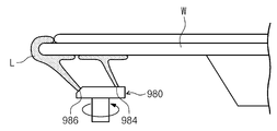
또한 본 실시예에는 백노즐(920)이 제1위치로 액을 공급하고, 이후에 제2위치로 액을 공급하는 것으로 설명하였다. 그러나 백노즐(920)의 제3실시예에 의하면, 도 16과 같이 백노즐(980)은 제1위치와 제2위치에 액을 동시 토출할 수 있다. 도 16을 참조하면, 백노즐(980)은 몸통부(982), 제1토출부(984), 그리고 제2토출부(986)를 가질 수 있다. 몸통부(982)는 지지 바디(836)에 설치되며, 구동기에 의해 회전 가능하도록 제공될 수 있다. 제1토출부(984)는 몸통부(982)의 상단으로부터 몸통부(982)의 길이 방향과 수직한 방향으로 연장되게 제공될 수 있다. 제1토출부(984)에는 제1토출구가 형성될 수 있다. 제2토출부(986)는 몸통부(982)의 상단으로부터 몸통부(982)의 길이 방향과 수직하게 연장되되, 제1토출부(984)와 반대되는 방향으로 연장될 수 있다. 제2토출부(986)에는 제2토출구가 형성될 수 있다. 제1토출구 및 제2토출구 각각에는 동일한 종류의 액이 토출될 수 있다. 제1토출부(984)는 제2토출부(986)에 비해 기판(W)의 중심축에 가깝게 위치될 수 있다. 상부에서 바라볼 때 제1토출부(984)와 제2토출부(986) 각각은 길이 방향이 기판(W)의 반경 방향과 평행하게 제공될 수 있다. 제1토출구로부터 토출되는 액은 제1위치로 공급되고, 제2토출구로부터 토출되는 액은 제2위치로 공급될 수 있다. 제1토출구 및 제2토출구 각각은 기판(W)의 중심축으로부터 멀어질수록 상향 경사진 방향을 향하도록 제공될 수 있다. 이에 따라 기판(W)으로부터 비산되는 액이 회전축에 부착되는 것을 방지할 수 있다. In addition, in this embodiment, it has been described that the
다시 도 3 및 도 4를 참조하면, 버퍼 챔버(3800)는 복수 개로 제공된다. 버퍼 챔버들(3800) 중 일부는 인덱스 모듈(20)과 반송 챔버(3400) 사이에 배치된다. 이하, 이들 버퍼 챔버를 전단 버퍼(3802)(front buffer)라 칭한다. 전단 버퍼들(3802)은 복수 개로 제공되며, 상하 방향을 따라 서로 적층되게 위치된다. 버퍼 챔버들(3802, 3804) 중 다른 일부는 반송 챔버(3400)와 인터페이스 모듈(40) 사이에 배치된다 이하. 이들 버퍼 챔버를 후단 버퍼(3804)(rear buffer)라 칭한다. 후단 버퍼들(3804)은 복수 개로 제공되며, 상하 방향을 따라 서로 적층되게 위치된다. 전단 버퍼들(3802) 및 후단 버퍼들(3804) 각각은 복수의 기판들(W)을 일시적으로 보관한다. 전단 버퍼(3802)에 보관된 기판(W)은 인덱스 로봇(2200) 및 반송 로봇(3422)에 의해 반입 또는 반출된다. 후단 버퍼(3804)에 보관된 기판(W)은 반송 로봇(3422) 및 제1로봇(4602)에 의해 반입 또는 반출된다. Referring back to FIGS. 3 and 4, a plurality of buffer chambers 3800 are provided. Some of the buffer chambers 3800 are disposed between the
현상 블럭(30b)은 열처리 챔버(3200), 반송 챔버(3400), 그리고 액처리 챔버(3600)를 가진다. 현상 블럭(30b)의 열처리 챔버(3200), 반송 챔버(3400), 그리고 액처리 챔버(3600)는 도포 블럭(30a)의 열처리 챔버(3200), 반송 챔버(3400), 그리고 액처리 챔버(3600)와 대체로 유사한 구조 및 배치로 제공되므로, 이에 대한된다. 다만, 현상 블록(30b)에서 액처리 챔버들(3600)은 모두 동일하게 현상액을 공급하여 기판을 현상 처리하는 현상 챔버(3600)로 제공된다.The developing
인터페이스 모듈(40)은 처리 모듈(30)을 외부의 노광 장치(50)와 연결한다. 인터페이스 모듈(40)은 인터페이스 프레임(4100), 부가 공정 챔버(4200), 인터페이스 버퍼(4400), 그리고 반송 부재(4600)를 가진다. The
인터페이스 프레임(4100)의 상단에는 내부에 하강기류를 형성하는 팬필터유닛이 제공될 수 있다. 부가 공정 챔버(4200), 인터페이스 버퍼(4400), 그리고 반송 부재(4600)는 인터페이스 프레임(4100)의 내부에 배치된다. 부가 공정 챔버(4200)는 도포 블럭(30a)에서 공정이 완료된 기판(W)이 노광 장치(50)로 반입되기 전에 소정의 부가 공정을 수행할 수 있다. 선택적으로 부가 공정 챔버(4200)는 노광 장치(50)에서 공정이 완료된 기판(W)이 현상 블럭(30b)으로 반입되기 전에 소정의 부가 공정을 수행할 수 있다. 일 예에 의하면, 부가 공정은 기판(W)의 에지 영역을 노광하는 에지 노광 공정, 또는 기판(W)의 상면을 세정하는 상면 세정 공정, 또는 기판(W)의 하면을 세정하는 하면 세정공정일 수 있다. 부가 공정 챔버(4200)는 복수 개가 제공되고, 이들은 서로 적층되도록 제공될 수 있다. 부가 공정 챔버(4200)는 모두 동일한 공정을 수행하도록 제공될 수 있다. 선택적으로 부가 공정 챔버(4200)들 중 일부는 서로 다른 공정을 수행하도록 제공될 수 있다.A fan filter unit may be provided at an upper end of the
인터페이스 버퍼(4400)는 도포 블럭(30a), 부가 공정챔버(4200), 노광 장치(50), 그리고 현상 블럭(30b) 간에 반송되는 기판(W)이 반송도중에 일시적으로 머무르는 공간을 제공한다. 인터페이스 버퍼(4400)는 복수 개가 제공되고, 복수의 인터페이스 버퍼들(4400)은 서로 적층되게 제공될 수 있다.The
일 예에 의하면, 반송 챔버(3400)의 길이 방향의 연장선을 기준으로 일 측면에는 부가 공정 챔버(4200)가 배치되고, 다른 측면에는 인터페이스 버퍼(4400)가 배치될 수 있다.According to an example, an
반송 부재(4600)는 도포 블럭(30a), 부가 공정챔버(4200), 노광 장치(50), 그리고 현상 블럭(30b) 간에 기판(W)을 반송한다. 반송 부재(4600)는 1개 또는 복수 개의 로봇으로 제공될 수 있다. 일 예에 의하면, 반송 부재(4600)는 제1로봇(4602) 및 제2로봇(4606)을 가진다. 제1로봇(4602)은 도포 블럭(30a), 부가 공정챔버(4200), 그리고 인터페이스 버퍼(4400) 간에 기판(W)을 반송하고, 인터페이스 로봇(4606)은 인터페이스 버퍼(4400)와 노광 장치(50) 간에 기판(W)을 반송하고, 제2로봇(4604)은 인터페이스 버퍼(4400)와 현상 블럭(30b) 간에 기판(W)을 반송하도록 제공될 수 있다.The conveying
제1로봇(4602) 및 제2로봇(4606)은 각각 기판(W)이 놓이는 핸드를 포함하며, 핸드는 전진 및 후진 이동, 제3 방향(16)에 평행한 축을 기준으로 한 회전, 그리고 제3 방향(16)을 따라 이동 가능하게 제공될 수 있다. Each of the
인덱스 로봇(2200), 제1로봇(4602), 그리고 제2 로봇(4606)의 핸드는 모두 반송 로봇(3422, 3424)의 핸드(3420)와 동일한 형상으로 제공될 수 있다. 선택적으로 열처리 챔버의 반송 플레이트(3240)와 직접 기판(W)을 주고받는 로봇의 핸드는 반송 로봇(3422, 3424)의 핸드(3420)와 동일한 형상으로 제공되고, 나머지 로봇의 핸드는 이와 상이한 형상으로 제공될 수 있다.The hand of the
일 실시예에 의하면, 인덱스 로봇(2200)은 도포 블럭(30a)에 제공된 전단 열처리 챔버(3200)의 가열 유닛(3230)과 직접 기판(W)을 주고받을 수 있도록 제공된다. According to an embodiment, the
또한, 도포 블럭(30a) 및 현상 블럭(30b)에 제공된 반송 로봇(3422)은 열처리 챔버(3200)에 위치된 반송 플레이트(3240)와 직접 기판(W)을 주고받을 수 있도록 제공될 수 있다. In addition, the
다음에는 상술한 기판 처리 장치(1)를 이용하여 기판을 처리하는 방법의 일 실시예에 대해 설명한다. Next, an embodiment of a method of processing a substrate using the
기판(W)에 대해 도포 처리 공정(S20), 에지 노광 공정(S40), 노광 공정(S60), 그리고 현상 처리 공정(S80)이 순차적으로 수행된다. A coating process (S20), an edge exposure process (S40), an exposure process (S60), and a developing process (S80) are sequentially performed on the substrate W.
도포 처리 공정(S20)은 열처리 챔버(3200)에서 열처리 공정(S21), 전단 액처리 챔버(3602)에서 반사방지막 도포 공정(S22), 열처리 챔버(3200)에서 열처리 공정(S23), 후단 액처리 챔버(3604)에서 포토레지스트막 도포 공정(S24), 그리고 열처리 챔버(3200)에서 열처리 공정(S25)이 순차적으로 이루어짐으로써 수행된다. The coating treatment process (S20) is a heat treatment process (S21) in the heat treatment chamber 3200, an antireflective coating process (S22) in the front
이하, 용기(10)에서 노광 장치(50)까지 기판(W)의 반송 경로의 일 예를 설명한다. Hereinafter, an example of a conveyance path of the substrate W from the
인덱스 로봇(2200)은 기판(W)을 용기(10)에서 꺼내서 전단 버퍼(3802)로 반송한다. 반송 로봇(3422)은 전단 버퍼(3802)에 보관된 기판(W)을 전단 열처리 챔버(3200)로 반송한다. 기판(W)은 반송 플레이트(3240)에 의해 가열 유닛(3230)에 기판(W)을 반송한다. 가열 유닛(3230)에서 기판의 가열 공정이 완료되면, 반송 플레이트(3240)는 기판을 냉각 유닛(3220)으로 반송한다. 반송 플레이트(3240)는 기판(W)을 지지한 상태에서, 냉각 유닛(3220)에 접촉되어 기판(W)의 냉각 공정을 수행한다. 냉각 공정이 완료되면, 반송 플레이트(3240)가 냉각 유닛(3220)의 상부로 이동되고, 반송 로봇(3422)은 열처리 챔버(3200)에서 기판(W)을 반출하여 전단 액처리 챔버(3602)로 반송한다. The
전단 액처리 챔버(3602)에서 기판(W) 상에 반사 방지막을 도포한다. An anti-reflection film is applied on the substrate W in the shear
반송 로봇(3422)이 전단 액처리 챔버(3602)에서 기판(W)을 반출하여 열처리 챔버(3200)로 기판(W)을 반입한다. 열처리 챔버(3200)에는 상술한 가열 공정 및 냉각 공정 순차적으로 진행되고, 각 열처리 공정이 완료되면, 반송 로봇(3422)은 기판(W)을 반출하여 후단 액처리 챔버(3604)로 반송한다. The
이후, 후단 액처리 챔버(3604)에서 기판(W) 상에 포토레지스트막을 도포한다. Thereafter, a photoresist film is applied on the substrate W in a
반송 로봇(3422)이 후단 액처리 챔버(3604)에서 기판(W)을 반출하여 열처리 챔버(3200)으로 기판(W)을 반입한다. 열처리 챔버(3200)에는 상술한 가열 공정 및 냉각 공정이 순차적으로 진행되고, 각 열처리 공정이 완료되면, 반송 로봇(3422)은 기판(W)을 후단 버퍼(3804)로 반송한다. 인터페이스 모듈(40)의 제1로봇(4602)이 후단 버퍼(3804)에서 기판(W)을 반출하여 보조 공정챔버(4200)로 반송한다. The
보조 공정챔버(4200)에서 기판(W)에 대해 에지 노광 공정이 수행된다.An edge exposure process is performed on the substrate W in the
이후, 제1로봇(4602)이 보조 공정챔버(4200)에서 기판(W)을 반출하여 인터페이스 버퍼(4400)로 기판(W)을 반송한다.Thereafter, the
이후, 제2로봇(4606)은 인터페이스 버퍼(4400)에서 기판(W)을 반출하여 노광 장치(50)로 반송한다.Thereafter, the
현상 처리 공정(S80)은 열처리 챔버(3200)에서 열처리 공정(S81), 액처리 챔버(3600)에서 현상 공정(S82), 그리고 열처리 챔버(3200)에서 열처리 공정(S83)이 순차적으로 이루어짐으로써 수행된다. The development treatment process (S80) is performed by sequentially performing a heat treatment process (S81) in the heat treatment chamber 3200, a development process (S82) in the
이하, 노광 장치(50)에서 용기(10)까지 기판(W)의 반송 경로의 일 예를 설명한다, Hereinafter, an example of a conveyance path of the substrate W from the
제2로봇(4606)이 노광 장치(50)에서 기판(W)을 반출하여 인터페이스 버퍼(4400)로 기판(W)을 반송한다.The
이후, 제1로봇(4602)이 인터페이스 버퍼(4400)에서 기판(W)을 반출하여 후단 버퍼(3804)로 기판(W)을 반송한다. 반송 로봇(3422)은 후단 버퍼(3804)에서 기판(W)을 반출하여 열처리 챔버(3200)로 기판(W)을 반송한다. 열처리 챔버(3200)에는 기판(W)의 가열 공정 및 냉각 공정이 순차적으로 수행한다. 냉각 공정이 완료되면, 기판(W)은 반송 로봇(3422)에 의해 현상 챔버(3600)로 반송한다. Thereafter, the
현상 챔버(3600)에는 기판(W) 상에 현상액을 공급하여 현상 공정을 수행한다. A developing process is performed by supplying a developer onto the substrate W to the developing
기판(W)은 반송 로봇(3422)에 의해 현상 챔버(3600)에서 반출되어 열처리 챔버(3200)로 반입된다. 기판(W)은 열처리 챔버(3200)에서 가열 공정 및 냉각 공정이 순차적으로 수행된다. 냉각 공정이 완료되면, 기판(W)은 반송 로봇(3422)에 의해 열처리 챔버(3200)에서 기판(W)을 반출되어 전단 버퍼(3802)로 반송한다. The substrate W is carried out from the developing
이후, 인덱스 로봇(2200)이 전단 버퍼(3802)에서 기판(W)을 꺼내어 용기(10)로 반송한다. Thereafter, the
상술한 기판 처리 장치(1)의 처리 블럭은 도포 처리 공정과 현상 처리 공정을 수행하는 것으로 설명하였다. 그러나 이와 달리 기판 처리 장치(1)는 인터페이스 모듈 없이 인덱스 모듈(20)과 처리 블럭(37)만을 구비할 수 있다. 이 경우, 처리 블럭(37)은 도포 처리 공정만을 수행하고, 기판(W) 상에 도포되는 막은 스핀 온 하드마스크막(SOH)일 수 있다.The processing block of the above-described
이상의 상세한 설명은 본 발명을 예시하는 것이다. 또한 상술한 내용은 본 발명의 바람직한 실시 형태를 나타내어 설명하는 것이며, 본 발명은 다양한 다른 조합, 변경 및 환경에서 사용할 수 있다. 즉 본 명세서에 개시된 발명의 개념의 범위, 저술한 개시 내용과 균등한 범위 및/또는 당업계의 기술 또는 지식의 범위내에서 변경 또는 수정이 가능하다. 저술한 실시예는 본 발명의 기술적 사상을 구현하기 위한 최선의 상태를 설명하는 것이며, 본 발명의 구체적인 적용 분야 및 용도에서 요구되는 다양한 변경도 가능하다. 따라서 이상의 발명의 상세한 설명은 개시된 실시 상태로 본 발명을 제한하려는 의도가 아니다. 또한 첨부된 청구범위는 다른 실시 상태도 포함하는 것으로 해석되어야 한다.The detailed description above is illustrative of the present invention. In addition, the above description shows and describes preferred embodiments of the present invention, and the present invention can be used in various other combinations, modifications and environments. That is, changes or modifications may be made within the scope of the concept of the invention disclosed in the present specification, the scope equivalent to the disclosed contents, and/or the skill or knowledge of the art. The above-described embodiments describe the best state for implementing the technical idea of the present invention, and various changes required in the specific application fields and uses of the present invention are possible. Therefore, the detailed description of the invention is not intended to limit the invention to the disclosed embodiment. In addition, the appended claims should be construed as including other embodiments.
830: 기판 지지 유닛
832; 지지판
834: 회전축
836: 지지 바디
920: 백노즐
922: 몸통부
924; 토출부830:
834: rotation shaft 836: support body
920: back nozzle 922: body
924; Discharge
Claims (19)
내부에 처리 공간을 제공하는 처리 용기와;
상기 처리 공간에서 기판을 지지하는 기판 지지 유닛과;
상기 기판 지지 유닛에 지지된 기판으로 액을 공급하는 액 공급 유닛을 포함하되,
상기 기판 지지 유닛은,
기판의 중심 영역이 놓이며, 기판의 가장자리 영역이 외부에 노출되도록 기판을 지지하고, 회전 가능한 지지판을 포함하며,
상기 액 공급 유닛은,
상기 지지판의 아래에서 기판의 저면으로 액을 공급하는 백노즐과;
상기 백노즐로부터 토출되는 액의 토출 위치가 제1위치와 상기 제1위치보다 기판의 중심에서 멀리 떨어진 제2위치로 변경되도록 상기 백노즐을 구동시키는 구동기를 포함하는 기판 처리 장치.In the apparatus for liquid processing a substrate,
A processing container providing a processing space therein;
A substrate support unit supporting a substrate in the processing space;
Including a liquid supply unit for supplying a liquid to the substrate supported by the substrate support unit,
The substrate support unit,
The center region of the substrate is placed, and the substrate supports the substrate so that the edge region of the substrate is exposed to the outside, and includes a rotatable support plate,
The liquid supply unit,
A back nozzle for supplying a liquid to a bottom surface of the substrate under the support plate;
A substrate processing apparatus comprising a driver for driving the back nozzle such that a discharge position of the liquid discharged from the back nozzle is changed to a first position and a second position farther from the center of the substrate than the first position.
상기 구동기를 제어하는 제어기를 더 포함하되,
상기 제어기는 상기 제2위치로 액을 토출하는 중에, 상기 구동기에 의해 상기 제2위치를 중심으로 일정 범위 내에서 토출 위치가 계속적으로 변경되도록 상기 구동기를 제어하는 기판 처리 장치.The method of claim 1,
Further comprising a controller for controlling the driver,
The controller controls the driver so that the discharge position is continuously changed within a predetermined range around the second position by the driver while the liquid is discharged to the second position.
상기 기판 지지 유닛은
상기 지지판을 지지하며, 회전되는 회전축과;
상기 회전축을 감싸며, 상기 지지판보다 큰 직경을 가지는 지지 바디를 포함하되,
상기 백노즐은 상기 지지 바디에 설치되는 기판 처리 장치.The method of claim 2,
The substrate support unit
A rotating shaft supporting the support plate and rotating;
Comprising a support body surrounding the rotating shaft and having a larger diameter than the support plate,
The back nozzle is a substrate processing apparatus installed on the support body.
상기 백노즐의 위치 변경은 상기 백노즐을 회전에 의해 이루어지도록 제공되는 기판 처리 장치.The method according to any one of claims 1 to 3,
The substrate processing apparatus is provided to change the position of the back nozzle by rotating the back nozzle.
상기 백노즐은,
상기 구동기에 의해 회전 가능한 몸통부와;
상기 몸통부에 지지되며, 액이 토출되는 토출구가 형성되는 토출부를 포함하되,
상기 토출구 및 상기 토출구에 액을 공급하는 토출 라인은 상기 몸통부의 중심축으로부터 이격되게 위치되는 기판 처리 장치.The method of claim 4,
The back nozzle,
A body rotatable by the driver;
It is supported on the body and includes a discharge portion formed with a discharge port through which the liquid is discharged,
The discharge port and the discharge line for supplying the liquid to the discharge port are positioned to be spaced apart from a central axis of the body.
상기 토출구는 위로 갈수록 상기 중심축으로부터 멀어지거나 가까워지는 방향을 향하는 기판 처리 장치.The method of claim 5,
The substrate processing apparatus of the discharge port toward a direction closer to or away from the central axis as it goes upward.
상기 백노즐의 위치 변경은 상기 백노즐을 직선 이동에 의해 이루어지도록 제공되는 기판 처리 장치.The method according to any one of claims 1 to 3,
The substrate processing apparatus is provided to change the position of the back nozzle by linearly moving the back nozzle.
상기 구동기는,
길이 방향이 상부에서 바라볼 때 기판의 중심축으로부터 멀어지는 방향으로 연장되는 가이드와;
상기 가이드의 길이 방향을 따라 이동 가능한 브라켓과;
상기 브라켓이 이동되도록 구동력을 제공하는 모터를 포함하고,
상기 백노즐은 상기 브라켓에 설치되는 기판 처리 장치.The method of claim 7,
The driver,
A guide extending in a direction away from the central axis of the substrate when the longitudinal direction is viewed from above;
A bracket movable along the length direction of the guide;
It includes a motor that provides a driving force to move the bracket,
The back nozzle is a substrate processing apparatus installed on the bracket.
상기 백노즐의 토출구는 기판의 중심축으로부터 멀어질수록 상향 경사진 방향을 향하도록 형성되는 기판 처리 장치.The method of claim 8,
A substrate processing apparatus wherein the discharge port of the back nozzle is formed to be inclined upward as it moves away from the central axis of the substrate.
내부에 처리 공간을 제공하는 처리 용기와;
상기 처리 공간에서 기판을 지지하는 기판 지지 유닛과;
상기 기판 지지 유닛에 지지된 기판으로 액을 공급하는 액 공급 유닛을 포함하되,
상기 기판 지지 유닛은,
기판의 중심 영역이 놓이며, 기판의 가장자리 영역이 외부에 노출되도록 기판을 지지하고, 회전 가능한 지지판을 포함하며,
상기 액 공급 유닛은,
상기 지지판의 아래에서 기판의 저면으로 액을 공급하는 백노즐을 포함하되,
상기 백 노즐에는 기판의 저면인 제1위치로 액을 토출하는 제1토출구와 상기 제1위치보다 기판의 중심에서 멀리 떨어진 기판의 저면인 제2위치로 액을 토출하는 제2토출구가 형성되는 기판 처리 장치.In the apparatus for liquid processing a substrate,
A processing container providing a processing space therein;
A substrate support unit supporting a substrate in the processing space;
Including a liquid supply unit for supplying a liquid to the substrate supported by the substrate support unit,
The substrate support unit,
The center region of the substrate is placed, and the substrate supports the substrate so that the edge region of the substrate is exposed to the outside, and includes a rotatable support plate,
The liquid supply unit,
Including a back nozzle for supplying a liquid to the bottom of the substrate under the support plate,
The back nozzle has a first discharge port for discharging the liquid to a first position, which is the bottom of the substrate, and a second discharge port for discharging the liquid to a second position, which is a lower surface of the substrate further from the center of the substrate than the first position. Processing device.
상기 액 공급 유닛은,
상기 백노즐을 회전시키는 구동기를 더 포함하되,
상기 백노즐은,
상기 구동기에 의해 회전 가능한 몸통부와;
상기 몸통부의 상단으로부터 수직한 방향으로 연장되며 상기 제1토출구가 형성되는 제1토출부와;
상기 몸통부의 상단으로부터 상기 제1토출부와 반대되는 방향으로 연장되며 상기 제2토출구가 형성되는 제2토출부를 포함하는 기판 처리 장치.The method of claim 10,
The liquid supply unit,
Further comprising a driver for rotating the back nozzle,
The back nozzle,
A body rotatable by the driver;
A first discharge portion extending in a vertical direction from an upper end of the body portion and having the first discharge port;
A substrate processing apparatus comprising a second discharge part extending in a direction opposite to the first discharge part from an upper end of the body part and in which the second discharge port is formed.
상기 제1토출구 및 상기 제2토출구 각각은 기판의 중심축으로부터 멀어질수록 상향 경사진 방향을 향하도록 제공되는 기판 처리 장치.The method of claim 11,
Each of the first discharge port and the second discharge port is provided to face an upwardly inclined direction as the distance from the central axis of the substrate increases.
회전되는 상기 기판의 저면에 액을 공급하여 상기 기판을 액 처리하되,
상기 기판의 아래에 위치되는 백 노즐은 상기 액을 상기 기판의 저면인 제1위치로 토출하여 상기 기판의 저면을 액 처리하고, 상기 액을 상기 제1위치보다 상기 기판의 중심에서 멀리 떨어지며 상기 기판의 저면인 제2위치로 토출하여 상기 기판의 베벨부를 액 처리하는 기판 처리 방법.In the method of liquid treatment of the substrate
Liquid-processing the substrate by supplying a liquid to the bottom of the rotating substrate,
The back nozzle positioned below the substrate discharges the liquid to a first position, which is the bottom surface of the substrate, and processes the bottom surface of the substrate. The liquid is further away from the center of the substrate than the first position, and the substrate A substrate processing method in which the bevel portion of the substrate is liquid-treated by discharging it to a second position that is the bottom of the substrate.
상기 액은 상기 제1위치로 토출된 후에 상기 제2위치로 토출되는 기판 처리 방법.The method of claim 13,
The substrate processing method wherein the liquid is discharged to the first position and then discharged to the second position.
상기 제1위치로 상기 액을 토출하는 것과 상기 제2위치로 상기 액을 토출하는 것 간의 변경은 상기 백 노즐을 회전 이동시킴으로써 이루어지는 기판 처리 방법.The method of claim 14,
A substrate processing method wherein a change between discharging the liquid to the first position and discharging the liquid to the second position is performed by rotating the back nozzle.
상기 제1위치에서 상기 기판을 액 처리하는 것은 상기 기판의 저면을 세정하는 세정 처리이고,
상기 제2위치에서 상기 기판을 액 처리하는 것은 상기 기판의 상면의 베벨부 영역에서 막질을 제거하는 제거 처리인 기판 처리 방법.The method according to any one of claims 13 to 14,
Liquid treatment of the substrate at the first position is a cleaning treatment for cleaning the bottom surface of the substrate,
The liquid treatment of the substrate at the second position is a removal treatment of removing a film quality from a bevel portion of the upper surface of the substrate.
상기 제2위치로 상기 액을 토출하는 중에는 상기 제2위치를 중심으로 일정 범위 내에서 토출 위치가 계속적으로 변경되는 기판 처리 방법.The method of claim 16,
While discharging the liquid to the second position, the discharging position is continuously changed within a predetermined range around the second position.
상기 기판의 상면에는 복수의 칩에 제공되며,
상기 제2위치를 중심으로 일정 범위 내에서 계속적으로 변경되는 토출되는 상기 칩에 액이 제공되지 않도록 하는 토출 위치인 기판 처리 방법.The method of claim 17,
It is provided on a plurality of chips on the upper surface of the substrate,
The substrate processing method of a substrate processing method in which a liquid is not provided to the discharged chip that is continuously changed within a predetermined range around the second position.
상기 세정 처리 및 상기 제거 처리는 상기 기판에 포토레지스트를 공급하는 처리 이후에 이루어지고,
상기 제거 처리에서 제거되는 막질은 포토레지스트 막인 기판 처리 방법.
The method of claim 18,
The cleaning treatment and the removal treatment are performed after a treatment of supplying a photoresist to the substrate,
A substrate processing method wherein the film quality removed in the removal treatment is a photoresist film.
Priority Applications (1)
| Application Number | Priority Date | Filing Date | Title |
|---|---|---|---|
| KR1020190075034A KR102378337B1 (en) | 2019-06-24 | 2019-06-24 | Apparatus and Method for treating substrate |
Applications Claiming Priority (1)
| Application Number | Priority Date | Filing Date | Title |
|---|---|---|---|
| KR1020190075034A KR102378337B1 (en) | 2019-06-24 | 2019-06-24 | Apparatus and Method for treating substrate |
Publications (2)
| Publication Number | Publication Date |
|---|---|
| KR20210000355A true KR20210000355A (en) | 2021-01-05 |
| KR102378337B1 KR102378337B1 (en) | 2022-03-25 |
Family
ID=74140733
Family Applications (1)
| Application Number | Title | Priority Date | Filing Date |
|---|---|---|---|
| KR1020190075034A KR102378337B1 (en) | 2019-06-24 | 2019-06-24 | Apparatus and Method for treating substrate |
Country Status (1)
| Country | Link |
|---|---|
| KR (1) | KR102378337B1 (en) |
Cited By (1)
| Publication number | Priority date | Publication date | Assignee | Title |
|---|---|---|---|---|
| KR20230024704A (en) * | 2021-08-12 | 2023-02-21 | 세메스 주식회사 | Apparatus for treating substrate and method for treating substrate |
Citations (2)
| Publication number | Priority date | Publication date | Assignee | Title |
|---|---|---|---|---|
| KR100637718B1 (en) * | 2005-10-04 | 2006-10-25 | 세메스 주식회사 | Single type semiconductor etching apparatus |
| KR20140114296A (en) * | 2013-03-18 | 2014-09-26 | 도쿄엘렉트론가부시키가이샤 | Fluid processing device |
-
2019
- 2019-06-24 KR KR1020190075034A patent/KR102378337B1/en active IP Right Grant
Patent Citations (2)
| Publication number | Priority date | Publication date | Assignee | Title |
|---|---|---|---|---|
| KR100637718B1 (en) * | 2005-10-04 | 2006-10-25 | 세메스 주식회사 | Single type semiconductor etching apparatus |
| KR20140114296A (en) * | 2013-03-18 | 2014-09-26 | 도쿄엘렉트론가부시키가이샤 | Fluid processing device |
Cited By (1)
| Publication number | Priority date | Publication date | Assignee | Title |
|---|---|---|---|---|
| KR20230024704A (en) * | 2021-08-12 | 2023-02-21 | 세메스 주식회사 | Apparatus for treating substrate and method for treating substrate |
Also Published As
| Publication number | Publication date |
|---|---|
| KR102378337B1 (en) | 2022-03-25 |
Similar Documents
| Publication | Publication Date | Title |
|---|---|---|
| KR101798320B1 (en) | Substrate processing apparatus | |
| US7641404B2 (en) | Substrate processing apparatus | |
| US7722267B2 (en) | Substrate processing apparatus | |
| KR102359530B1 (en) | Method and Apparatus for treating substrate, and Method for cleaning cup | |
| US20060152693A1 (en) | Substrate processing apparatus | |
| CN108803257B (en) | Liquid supply unit, substrate processing apparatus, and substrate processing method | |
| US20100129526A1 (en) | Substrate processing apparatus | |
| US7690853B2 (en) | Substrate processing apparatus | |
| KR102121240B1 (en) | Apparatus and Method for treating substrate | |
| KR101977752B1 (en) | Apparatus and Method for treating a substrate | |
| KR102288984B1 (en) | Apparatus and Method for treating substrate | |
| KR102378337B1 (en) | Apparatus and Method for treating substrate | |
| KR20210011197A (en) | Apparatus for treating substrate | |
| KR101884854B1 (en) | Apparatus and Method for treating substrate | |
| KR102303594B1 (en) | Apparatus and method for treating a substrate | |
| KR20200093087A (en) | Apparatus and Methof for treating substrate | |
| KR102175076B1 (en) | Apparatus and Method for treating substrate | |
| KR102270937B1 (en) | Apparatus and Method for treating substrate | |
| KR102010261B1 (en) | Apparatus and Method for treating a substrate | |
| KR102243066B1 (en) | Apparatus for treating substrate | |
| KR102324407B1 (en) | Unit for supplying liquid, Apparatus and Method for treating substrate with the unit | |
| KR102243063B1 (en) | Unit for supplying liquid, Apparatus for treating substrate, and Method for treating substrate | |
| KR102281045B1 (en) | Apparatus and Method for treating substrate | |
| KR102666439B1 (en) | Nozzle Apparatus and Apparatus for treating substrate | |
| KR102289939B1 (en) | Apparatus and Method for treating substrate |
Legal Events
| Date | Code | Title | Description |
|---|---|---|---|
| AMND | Amendment | ||
| AMND | Amendment | ||
| E601 | Decision to refuse application | ||
| AMND | Amendment | ||
| E90F | Notification of reason for final refusal | ||
| AMND | Amendment | ||
| X701 | Decision to grant (after re-examination) | ||
| GRNT | Written decision to grant |