KR20200096704A - Electronic device, method and storage medium for wireless communication system - Google Patents
Electronic device, method and storage medium for wireless communication system Download PDFInfo
- Publication number
- KR20200096704A KR20200096704A KR1020207022681A KR20207022681A KR20200096704A KR 20200096704 A KR20200096704 A KR 20200096704A KR 1020207022681 A KR1020207022681 A KR 1020207022681A KR 20207022681 A KR20207022681 A KR 20207022681A KR 20200096704 A KR20200096704 A KR 20200096704A
- Authority
- KR
- South Korea
- Prior art keywords
- terminal device
- base station
- transmission
- transmit
- beams
- Prior art date
Links
- 230000006854 communication Effects 0.000 title claims abstract description 210
- 238000004891 communication Methods 0.000 title claims abstract description 206
- 238000000034 method Methods 0.000 title claims abstract description 201
- 230000005540 biological transmission Effects 0.000 claims abstract description 741
- 238000012545 processing Methods 0.000 claims abstract description 51
- 230000008569 process Effects 0.000 claims description 63
- 230000011664 signaling Effects 0.000 claims description 19
- 108010076504 Protein Sorting Signals Proteins 0.000 claims description 12
- 230000004044 response Effects 0.000 claims description 6
- 230000006870 function Effects 0.000 description 28
- 230000009977 dual effect Effects 0.000 description 14
- 238000005516 engineering process Methods 0.000 description 12
- 230000008901 benefit Effects 0.000 description 11
- 238000010586 diagram Methods 0.000 description 10
- 230000015572 biosynthetic process Effects 0.000 description 6
- 230000010267 cellular communication Effects 0.000 description 6
- 125000004122 cyclic group Chemical group 0.000 description 6
- 230000008054 signal transmission Effects 0.000 description 6
- 238000012986 modification Methods 0.000 description 5
- 230000004048 modification Effects 0.000 description 5
- 239000004065 semiconductor Substances 0.000 description 4
- 238000011161 development Methods 0.000 description 3
- 238000005259 measurement Methods 0.000 description 3
- 230000003287 optical effect Effects 0.000 description 3
- 230000006978 adaptation Effects 0.000 description 2
- 238000013459 approach Methods 0.000 description 2
- 230000006399 behavior Effects 0.000 description 2
- 238000004364 calculation method Methods 0.000 description 2
- 238000007796 conventional method Methods 0.000 description 2
- 238000001514 detection method Methods 0.000 description 2
- 230000000694 effects Effects 0.000 description 2
- 230000010365 information processing Effects 0.000 description 2
- 239000004973 liquid crystal related substance Substances 0.000 description 2
- 238000013146 percutaneous coronary intervention Methods 0.000 description 2
- 230000005236 sound signal Effects 0.000 description 2
- 238000010521 absorption reaction Methods 0.000 description 1
- 230000001133 acceleration Effects 0.000 description 1
- 230000001413 cellular effect Effects 0.000 description 1
- 230000008859 change Effects 0.000 description 1
- 230000001149 cognitive effect Effects 0.000 description 1
- 230000000295 complement effect Effects 0.000 description 1
- 238000004590 computer program Methods 0.000 description 1
- 239000012141 concentrate Substances 0.000 description 1
- 238000012790 confirmation Methods 0.000 description 1
- 238000005562 fading Methods 0.000 description 1
- 230000003993 interaction Effects 0.000 description 1
- 230000007774 longterm Effects 0.000 description 1
- 229910044991 metal oxide Inorganic materials 0.000 description 1
- 150000004706 metal oxides Chemical class 0.000 description 1
- 239000013307 optical fiber Substances 0.000 description 1
- 230000009467 reduction Effects 0.000 description 1
- 230000003252 repetitive effect Effects 0.000 description 1
- 238000007493 shaping process Methods 0.000 description 1
- 238000001228 spectrum Methods 0.000 description 1
- 238000006467 substitution reaction Methods 0.000 description 1
- 230000001360 synchronised effect Effects 0.000 description 1
- 238000012549 training Methods 0.000 description 1
- 238000012546 transfer Methods 0.000 description 1
- 239000002699 waste material Substances 0.000 description 1
Images


Classifications
-
- H—ELECTRICITY
- H04—ELECTRIC COMMUNICATION TECHNIQUE
- H04B—TRANSMISSION
- H04B7/00—Radio transmission systems, i.e. using radiation field
- H04B7/02—Diversity systems; Multi-antenna system, i.e. transmission or reception using multiple antennas
- H04B7/04—Diversity systems; Multi-antenna system, i.e. transmission or reception using multiple antennas using two or more spaced independent antennas
- H04B7/06—Diversity systems; Multi-antenna system, i.e. transmission or reception using multiple antennas using two or more spaced independent antennas at the transmitting station
- H04B7/0613—Diversity systems; Multi-antenna system, i.e. transmission or reception using multiple antennas using two or more spaced independent antennas at the transmitting station using simultaneous transmission
- H04B7/0615—Diversity systems; Multi-antenna system, i.e. transmission or reception using multiple antennas using two or more spaced independent antennas at the transmitting station using simultaneous transmission of weighted versions of same signal
- H04B7/0617—Diversity systems; Multi-antenna system, i.e. transmission or reception using multiple antennas using two or more spaced independent antennas at the transmitting station using simultaneous transmission of weighted versions of same signal for beam forming
-
- H—ELECTRICITY
- H04—ELECTRIC COMMUNICATION TECHNIQUE
- H04B—TRANSMISSION
- H04B7/00—Radio transmission systems, i.e. using radiation field
- H04B7/02—Diversity systems; Multi-antenna system, i.e. transmission or reception using multiple antennas
- H04B7/04—Diversity systems; Multi-antenna system, i.e. transmission or reception using multiple antennas using two or more spaced independent antennas
- H04B7/0408—Diversity systems; Multi-antenna system, i.e. transmission or reception using multiple antennas using two or more spaced independent antennas using two or more beams, i.e. beam diversity
-
- H—ELECTRICITY
- H04—ELECTRIC COMMUNICATION TECHNIQUE
- H04B—TRANSMISSION
- H04B7/00—Radio transmission systems, i.e. using radiation field
- H04B7/02—Diversity systems; Multi-antenna system, i.e. transmission or reception using multiple antennas
- H04B7/04—Diversity systems; Multi-antenna system, i.e. transmission or reception using multiple antennas using two or more spaced independent antennas
- H04B7/0413—MIMO systems
- H04B7/0417—Feedback systems
-
- H—ELECTRICITY
- H04—ELECTRIC COMMUNICATION TECHNIQUE
- H04B—TRANSMISSION
- H04B7/00—Radio transmission systems, i.e. using radiation field
- H04B7/02—Diversity systems; Multi-antenna system, i.e. transmission or reception using multiple antennas
- H04B7/04—Diversity systems; Multi-antenna system, i.e. transmission or reception using multiple antennas using two or more spaced independent antennas
- H04B7/06—Diversity systems; Multi-antenna system, i.e. transmission or reception using multiple antennas using two or more spaced independent antennas at the transmitting station
- H04B7/0613—Diversity systems; Multi-antenna system, i.e. transmission or reception using multiple antennas using two or more spaced independent antennas at the transmitting station using simultaneous transmission
- H04B7/0615—Diversity systems; Multi-antenna system, i.e. transmission or reception using multiple antennas using two or more spaced independent antennas at the transmitting station using simultaneous transmission of weighted versions of same signal
- H04B7/0619—Diversity systems; Multi-antenna system, i.e. transmission or reception using multiple antennas using two or more spaced independent antennas at the transmitting station using simultaneous transmission of weighted versions of same signal using feedback from receiving side
- H04B7/0621—Feedback content
- H04B7/0626—Channel coefficients, e.g. channel state information [CSI]
-
- H—ELECTRICITY
- H04—ELECTRIC COMMUNICATION TECHNIQUE
- H04B—TRANSMISSION
- H04B7/00—Radio transmission systems, i.e. using radiation field
- H04B7/02—Diversity systems; Multi-antenna system, i.e. transmission or reception using multiple antennas
- H04B7/04—Diversity systems; Multi-antenna system, i.e. transmission or reception using multiple antennas using two or more spaced independent antennas
- H04B7/06—Diversity systems; Multi-antenna system, i.e. transmission or reception using multiple antennas using two or more spaced independent antennas at the transmitting station
- H04B7/0686—Hybrid systems, i.e. switching and simultaneous transmission
- H04B7/0695—Hybrid systems, i.e. switching and simultaneous transmission using beam selection
-
- H—ELECTRICITY
- H04—ELECTRIC COMMUNICATION TECHNIQUE
- H04B—TRANSMISSION
- H04B7/00—Radio transmission systems, i.e. using radiation field
- H04B7/02—Diversity systems; Multi-antenna system, i.e. transmission or reception using multiple antennas
- H04B7/04—Diversity systems; Multi-antenna system, i.e. transmission or reception using multiple antennas using two or more spaced independent antennas
- H04B7/08—Diversity systems; Multi-antenna system, i.e. transmission or reception using multiple antennas using two or more spaced independent antennas at the receiving station
- H04B7/0868—Hybrid systems, i.e. switching and combining
- H04B7/088—Hybrid systems, i.e. switching and combining using beam selection
-
- H—ELECTRICITY
- H04—ELECTRIC COMMUNICATION TECHNIQUE
- H04L—TRANSMISSION OF DIGITAL INFORMATION, e.g. TELEGRAPHIC COMMUNICATION
- H04L5/00—Arrangements affording multiple use of the transmission path
-
- H—ELECTRICITY
- H04—ELECTRIC COMMUNICATION TECHNIQUE
- H04L—TRANSMISSION OF DIGITAL INFORMATION, e.g. TELEGRAPHIC COMMUNICATION
- H04L5/00—Arrangements affording multiple use of the transmission path
- H04L5/0001—Arrangements for dividing the transmission path
- H04L5/0014—Three-dimensional division
- H04L5/0023—Time-frequency-space
-
- H—ELECTRICITY
- H04—ELECTRIC COMMUNICATION TECHNIQUE
- H04L—TRANSMISSION OF DIGITAL INFORMATION, e.g. TELEGRAPHIC COMMUNICATION
- H04L5/00—Arrangements affording multiple use of the transmission path
- H04L5/003—Arrangements for allocating sub-channels of the transmission path
- H04L5/0048—Allocation of pilot signals, i.e. of signals known to the receiver
- H04L5/005—Allocation of pilot signals, i.e. of signals known to the receiver of common pilots, i.e. pilots destined for multiple users or terminals
-
- H—ELECTRICITY
- H04—ELECTRIC COMMUNICATION TECHNIQUE
- H04L—TRANSMISSION OF DIGITAL INFORMATION, e.g. TELEGRAPHIC COMMUNICATION
- H04L5/00—Arrangements affording multiple use of the transmission path
- H04L5/003—Arrangements for allocating sub-channels of the transmission path
- H04L5/0048—Allocation of pilot signals, i.e. of signals known to the receiver
- H04L5/0051—Allocation of pilot signals, i.e. of signals known to the receiver of dedicated pilots, i.e. pilots destined for a single user or terminal
-
- H—ELECTRICITY
- H04—ELECTRIC COMMUNICATION TECHNIQUE
- H04L—TRANSMISSION OF DIGITAL INFORMATION, e.g. TELEGRAPHIC COMMUNICATION
- H04L5/00—Arrangements affording multiple use of the transmission path
- H04L5/0091—Signaling for the administration of the divided path
- H04L5/0092—Indication of how the channel is divided
-
- H—ELECTRICITY
- H04—ELECTRIC COMMUNICATION TECHNIQUE
- H04W—WIRELESS COMMUNICATION NETWORKS
- H04W56/00—Synchronisation arrangements
- H04W56/001—Synchronization between nodes
-
- H—ELECTRICITY
- H04—ELECTRIC COMMUNICATION TECHNIQUE
- H04W—WIRELESS COMMUNICATION NETWORKS
- H04W74/00—Wireless channel access
- H04W74/002—Transmission of channel access control information
- H04W74/004—Transmission of channel access control information in the uplink, i.e. towards network
-
- H—ELECTRICITY
- H04—ELECTRIC COMMUNICATION TECHNIQUE
- H04W—WIRELESS COMMUNICATION NETWORKS
- H04W74/00—Wireless channel access
- H04W74/08—Non-scheduled access, e.g. ALOHA
- H04W74/0833—Random access procedures, e.g. with 4-step access
-
- H—ELECTRICITY
- H04—ELECTRIC COMMUNICATION TECHNIQUE
- H04L—TRANSMISSION OF DIGITAL INFORMATION, e.g. TELEGRAPHIC COMMUNICATION
- H04L5/00—Arrangements affording multiple use of the transmission path
- H04L5/003—Arrangements for allocating sub-channels of the transmission path
- H04L5/0053—Allocation of signaling, i.e. of overhead other than pilot signals
Landscapes
- Engineering & Computer Science (AREA)
- Signal Processing (AREA)
- Computer Networks & Wireless Communication (AREA)
- Mobile Radio Communication Systems (AREA)
- Radar Systems Or Details Thereof (AREA)
- Transceivers (AREA)
Abstract
본 개시내용은 무선 통신 시스템을 위한 전자 디바이스들, 방법들, 및 저장 매체에 관한 것이다. 빔 관리에 관한 다양한 실시예들이 설명된다. 일 실시예에서, 무선 통신 시스템 내의 기지국 측을 위한 전자 디바이스는 처리 회로 시스템을 포함할 수 있다. 처리 회로 시스템은 전송 빔 구성에 기초하여 상이한 전송 빔들을 사용하여 단말 디바이스에 동기화 신호를 반복적으로 송신하도록 구성되고, 동기화 신호는 동기화 신호를 송신하기 위해 사용되는 전송 빔 정보를 나타낼 수 있다. 처리 회로 시스템은 단말 디바이스로부터 피드백을 취득하도록 구성될 수 있고; 피드백은 전송 빔을 관리하기 위한 전송 빔 정보를 포함할 수 있다.The present disclosure relates to electronic devices, methods, and storage media for a wireless communication system. Various embodiments of beam management are described. In one embodiment, an electronic device for the base station side in a wireless communication system may comprise a processing circuit system. The processing circuit system is configured to repeatedly transmit the synchronization signal to the terminal device using different transmission beams based on the transmission beam configuration, and the synchronization signal may represent transmission beam information used to transmit the synchronization signal. The processing circuit system can be configured to obtain feedback from the terminal device; The feedback may include transmission beam information for managing the transmission beam.
Description
본 개시내용은 일반적으로 무선 통신 시스템에 관한 것으로, 구체적으로는 빔 형성에 관련된 빔 관리 기술들에 관한 것이다.TECHNICAL FIELD The present disclosure relates generally to wireless communication systems, and in particular to beam management techniques related to beamforming.
최근 몇 년 동안, 모바일 인터넷 기술이 발전하고 폭넓게 적용됨에 따라, 무선 통신은 전례 없이 음성 및 데이터 통신에 대한 사람들의 요구를 충족시켰다. 훨씬 더 높은 통신 품질 및 용량을 제공하기 위해, 무선 통신 시스템은 상이한 계층들에서 빔 형성 기술들(beamforming techniques)과 같은 다양한 기술들을 사용한다. 빔 형성은 안테나 전송 및/또는 수신의 지향성을 증가시킴으로써 무선 신호 손실을 보상하기 위해 빔 형성 이득을 제공할 수 있다. [예를 들어, NR(New Radio) 시스템과 같은 5G 시스템과 같은] 장래의 무선 통신 시스템에서, 기지국 및 단말 디바이스 측의 안테나 포트들의 수는 더 증가할 것이다. 예를 들어, 기지국 측의 안테나 포트의 수는 수백 개 또는 심지어 그보다 더 많은 수로 증가하여, 대규모 MIMO 시스템을 구성할 수 있다. 따라서, 대규모 안테나 시스템에서, 빔 형성은 더 큰 적용 공간을 가질 것이다.In recent years, as mobile Internet technology has evolved and has been widely applied, wireless communication has unprecedentedly met people's needs for voice and data communication. To provide even higher communication quality and capacity, wireless communication systems use various techniques, such as beamforming techniques at different layers. Beamforming can provide a beamforming gain to compensate for wireless signal loss by increasing the directivity of antenna transmission and/or reception. In a future wireless communication system (such as a 5G system, such as a New Radio (NR) system, for example), the number of antenna ports on the base station and terminal device side will further increase. For example, the number of antenna ports on the base station side is increased to several hundred or even more, so that a large-scale MIMO system can be configured. Thus, in a large-scale antenna system, beamforming will have a larger application space.
현재, 빔 형성은 기지국과 단말 디바이스 사이의 데이터 송수신 프로세스에 더 많이 사용된다. 그러나, 단말 디바이스와 기지국[예를 들어, 동기화 신호(SS)를 전송하는 기지국, 및 랜덤 액세스 신호를 기지국에 전송하는 단말 디바이스를 포함함] 사이의 초기 접속/동기화는 단말 디바이스가 기지국과 적절히 통신할 수 있게 하는 제1 단계이다. 따라서, 단말 디바이스와 기지국 사이의 초기 접속/동기화를 위해 빔 형성 기술이 고려될 수 있다. 예를 들어, 빔 형성 기술은 동기화 신호의 송수신 프로세스는 물론, 랜덤 액세스 신호의 송수신 프로세스를 위해 고려될 수 있다.Currently, beamforming is used more in the process of transmitting and receiving data between a base station and a terminal device. However, the initial connection/synchronization between the terminal device and the base station (e.g., including a base station that transmits a synchronization signal (SS) and a terminal device that transmits a random access signal to the base station) allows the terminal device to properly communicate with the base station. This is the first step in making it possible. Accordingly, a beamforming technique may be considered for initial connection/synchronization between the terminal device and the base station. For example, the beamforming technique may be considered for a process of transmitting and receiving a synchronization signal as well as a process of transmitting and receiving a random access signal.
본 개시내용의 양태들은 무선 통신 시스템의 빔 형성 기술들에서의 빔 관리에 관한 것이다.Aspects of the present disclosure relate to beam management in beamforming techniques of a wireless communication system.
본 개시내용의 일 양태는 무선 통신 시스템 내의 기지국 측을 위한 전자 디바이스에 관한 것이다. 일 실시예에 따르면, 전자 디바이스는 처리 회로를 포함할 수 있다. 처리 회로는 전송 빔 구성에 기초하여 상이한 전송 빔들을 사용하여 단말 디바이스에 동기화 신호를 반복적으로 전송하도록 구성될 수 있고, 동기화 신호는 동기화 신호를 전송하기 위해 사용되는 전송 빔의 정보를 나타낸다. 처리 회로는 단말 디바이스로부터 피드백을 획득하도록 추가로 구성될 수 있고, 피드백은 전송 빔 관리에서 사용되기 위한 전송 빔의 정보를 포함한다.One aspect of the present disclosure relates to an electronic device for a base station side in a wireless communication system. According to one embodiment, the electronic device may include a processing circuit. The processing circuit may be configured to repeatedly transmit a synchronization signal to the terminal device using different transmission beams based on the transmission beam configuration, and the synchronization signal represents information of a transmission beam used to transmit the synchronization signal. The processing circuit may be further configured to obtain feedback from the terminal device, and the feedback includes information of a transmission beam for use in transmission beam management.
본 개시내용의 다른 양태는 무선 통신 시스템 내의 단말 디바이스 측을 위한 전자 디바이스에 관한 것이다. 일 실시예에 따르면, 전자 디바이스는 처리 회로를 포함한다. 처리 회로는 무선 통신 시스템의 기지국 측의 전송 빔 구성에 기초하여 동기화 신호를 수신하도록 구성될 수 있고, 동기화 신호는 기지국에 의해 동기화 신호를 전송하기 위해 사용되는 전송 빔의 정보를 나타낼 수 있다. 처리 회로는 기지국에 피드백을 제공하도록 추가로 구성될 수 있고, 피드백은 전송 빔 관리에서 기지국에 의해 사용되기 위한 전송 빔의 정보를 포함할 수 있다.Another aspect of the present disclosure relates to an electronic device for a terminal device side in a wireless communication system. According to one embodiment, the electronic device comprises a processing circuit. The processing circuit may be configured to receive a synchronization signal based on a transmission beam configuration of the base station side of the wireless communication system, and the synchronization signal may represent information of a transmission beam used by the base station to transmit the synchronization signal. The processing circuitry may be further configured to provide feedback to the base station, and the feedback may include information of the transmit beam for use by the base station in transmit beam management.
본 개시내용의 다른 양태는 무선 통신의 방법에 관한 것이다. 일 실시예에서, 방법은 전송 빔 구성에 기초하여 상이한 전송 빔을 사용하여 단말 디바이스에 동기화 신호를 반복적으로 전송하는 단계 - 동기화 신호는 동기화 신호를 전송하기 위해 사용되는 전송 빔의 정보를 나타낼 수 있음 -; 및 단말 디바이스로부터 피드백을 획득하는 단계 - 피드백은 전송 빔 관리에서 기지국에 의해 사용되기 위한 전송 빔의 정보를 포함함 - 를 포함할 수 있다.Another aspect of the present disclosure relates to a method of wireless communication. In one embodiment, the method includes repeatedly transmitting a synchronization signal to a terminal device using different transmission beams based on a transmission beam configuration-the synchronization signal may indicate information of a transmission beam used to transmit the synchronization signal. -; And obtaining feedback from the terminal device, wherein the feedback includes information on a transmission beam to be used by a base station in transmission beam management.
본 개시내용의 다른 양태는 무선 통신의 다른 방법에 관한 것이다. 일 실시예에서, 방법은 무선 통신 시스템 내의 기지국 측의 전송 빔 구성에 기초하여 동기화 신호를 수신하는 단계 - 동기화 신호는 기지국에 의해 동기화 신호를 전송하기 위해 사용되는 전송 빔의 정보를 나타낼 수 있음 -; 및 기지국에 피드백을 제공하는 단계 - 피드백은 전송 빔 관리에서 사용되기 위한 전송 빔의 정보를 포함함 - 를 포함할 수 있다.Another aspect of the present disclosure relates to another method of wireless communication. In one embodiment, the method comprises receiving a synchronization signal based on a transmission beam configuration of a base station in a wireless communication system-the synchronization signal may represent information of a transmission beam used by the base station to transmit a synchronization signal- ; And providing feedback to the base station-the feedback includes information on a transmission beam to be used in transmission beam management.
본 개시내용의 다른 양태는 무선 통신 시스템 내의 기지국 측을 위한 전자 디바이스에 관한 것이다. 일 실시예에 따르면, 전자 디바이스는 처리 회로를 포함할 수 있다. 처리 회로는 전송 빔 구성에 기초하여 단말 디바이스에 동기화 신호를 전송하는 다른 기지국으로부터 전송 빔 구성을 수신하도록 구성될 수 있다. 처리 회로는 단말 디바이스에 전송 빔 구성을 전송하도록 추가로 구성될 수 있다.Another aspect of the present disclosure relates to an electronic device for a base station side in a wireless communication system. According to one embodiment, the electronic device may include a processing circuit. The processing circuitry may be configured to receive the transmit beam configuration from another base station that transmits a synchronization signal to the terminal device based on the transmit beam configuration. The processing circuit may be further configured to transmit the transmission beam configuration to the terminal device.
본 개시내용의 다른 양태는 무선 통신 시스템 내의 단말 디바이스 측을 위한 전자 디바이스에 관한 것이다. 일 실시예에 따르면, 전자 디바이스는 처리 회로를 포함한다. 처리 회로는 랜덤 액세스 구성 정보를 획득하고; 다운링크에서 단말 디바이스 측에서의 하나 이상의 수신 빔과 쌍을 이루는 기지국 측에서의 하나 이상의 전송 빔을 나타내기 위해 랜덤 액세스 구성 정보에 기초하여 랜덤 액세스 프리앰블을 전송하도록 구성될 수 있다.Another aspect of the present disclosure relates to an electronic device for a terminal device side in a wireless communication system. According to one embodiment, the electronic device comprises a processing circuit. The processing circuitry obtains random access configuration information; It may be configured to transmit a random access preamble based on random access configuration information in order to indicate one or more transmission beams at a base station side paired with at least one reception beam at the terminal device in the downlink.
본 개시내용의 다른 양태는 무선 통신 시스템 내의 기지국 측을 위한 전자 디바이스에 관한 것이다. 일 실시예에 따르면, 전자 디바이스는 처리 회로를 포함할 수 있다. 처리 회로는 랜덤 액세스 구성 정보를 전송하고; 다운링크에서 단말 디바이스 측에서의 하나 이상의 수신 빔과 쌍을 이루는 기지국 측에서의 하나 이상의 전송 빔을 획득하기 위해 단말 디바이스로부터 전송된 랜덤 액세스 프리앰블을 수신하도록 구성될 수 있다.Another aspect of the present disclosure relates to an electronic device for a base station side in a wireless communication system. According to one embodiment, the electronic device may include a processing circuit. The processing circuitry transmits random access configuration information; It may be configured to receive the random access preamble transmitted from the terminal device in order to obtain one or more transmission beams at the base station side paired with the at least one reception beam at the terminal device side in the downlink.
본 개시내용의 다른 양태는 무선 통신의 방법에 관한 것이다. 일 실시예에서, 방법은 랜덤 액세스 구성 정보를 획득하는 단계; 및 다운링크에서 단말 디바이스 측에서의 하나 이상의 수신 빔과 쌍을 이루는 기지국 측에서의 하나 이상의 전송 빔을 나타내기 위해 랜덤 액세스 구성 정보에 기초하여 랜덤 액세스 프리앰블을 전송하는 단계를 포함할 수 있다.Another aspect of the present disclosure relates to a method of wireless communication. In one embodiment, a method includes obtaining random access configuration information; And transmitting a random access preamble based on random access configuration information to indicate one or more transmission beams at a base station side paired with at least one reception beam at a terminal device in a downlink.
본 개시내용의 다른 양태는 무선 통신의 다른 방법에 관한 것이다. 일 실시예에서, 방법은 랜덤 액세스 구성 정보를 전송하는 단계; 및 다운링크에서 단말 디바이스 측에서의 하나 이상의 수신 빔과 쌍을 이루는 기지국 측에서의 하나 이상의 전송 빔을 획득하기 위해 단말 디바이스로부터 전송된 랜덤 액세스 프리앰블을 수신하는 단계를 포함할 수 있다.Another aspect of the present disclosure relates to another method of wireless communication. In one embodiment, a method includes transmitting random access configuration information; And receiving a random access preamble transmitted from the terminal device in order to obtain one or more transmission beams at the base station side paired with the at least one reception beam at the terminal device in the downlink.
본 개시내용의 다른 양태는 하나 이상의 명령어를 저장하는 컴퓨터 판독가능한 저장 매체에 관한 것이다. 일부 실시예들에서, 하나 이상의 명령어는 전자 디바이스의 하나 이상의 프로세서에 의해 실행될 때, 전자 디바이스로 하여금 본 명세서의 다양한 실시예들에 따른 방법들을 수행하게 할 수 있다.Another aspect of the present disclosure relates to a computer-readable storage medium storing one or more instructions. In some embodiments, the one or more instructions, when executed by the one or more processors of the electronic device, may cause the electronic device to perform methods according to various embodiments of the present disclosure.
본 개시내용의 다른 양태는 본 명세서의 실시예들에 따른 방법들의 동작들을 수행하기 위한 수단들 또는 유닛들을 포함하는 다양한 장치에 관한 것이다.Another aspect of the present disclosure relates to various apparatus comprising means or units for performing operations of methods according to embodiments herein.
상기 개요는 본 명세서에 설명된 발명의 주제의 다양한 양태들의 기본적인 이해를 제공하도록 일부 예시적인 실시예들을 요약하기 위해 제공된다. 따라서, 위에서 설명된 특징들은 단지 예일 뿐이며, 본 명세서에 설명된 발명의 주제의 범위 또는 사상을 어떤 방식으로든 제한하는 것으로 해석되어서는 안 된다. 본 명세서에 설명된 발명의 주제의 다른 특징들, 양태들, 및 이점들은 도면들과 관련하여 이하에 설명되는 상세한 설명으로부터 명백해질 것이다.The above summary is provided to summarize some exemplary embodiments to provide a basic understanding of various aspects of the subject matter of the invention described herein. Accordingly, the features described above are merely examples and should not be construed as limiting in any way the scope or spirit of the subject matter of the invention described herein. Other features, aspects, and advantages of the subject matter of the invention described herein will become apparent from the detailed description set forth below in connection with the drawings.
본 개시내용의 더 나은 이해는 첨부 도면과 관련하여 이하에 주어진 상세한 설명을 참조함으로써 달성될 수 있으며, 동일한 또는 유사한 참조 부호들은 도면 전체에 걸쳐 동일한 또는 유사한 컴포넌트들을 나타내기 위해 사용된다. 이 도면들은 본 명세서의 실시예들을 더 설명하고 본 개시내용의 이론 및 이점들을 설명하기 위해, 명세서에 포함되고 이하의 상세한 설명과 함께 명세서의 일부를 형성한다.
도 1은 무선 통신 시스템에서의 예시적인 셀 동기화 및 랜덤 액세스 프로세스를 도시한다.
도 2a-도 2d는 빔 형성 기술에서의 예시적인 빔 스캐닝 프로세스를 도시한다.
도 3a는 본 명세서의 실시예에 따른 기지국 측을 위한 예시적인 전자 디바이스를 도시한다.
도 3b는 본 명세서의 실시예에 따른 단말 디바이스 측을 위한 예시적인 전자 디바이스를 도시한다.
도 4a-도 4d는 본 명세서의 실시예에 따른 동기화 신호에 대한 예시적인 시간 도메인 주파수 도메인 자원들을 도시한다.
도 5a 및 도 5b는 본 명세서의 실시예에 따른 예시적인 동기화 신호 시간 윈도우를 도시한다.
도 6a-도 6c는 본 명세서의 실시예에 따른 기지국 측의 예시적인 전송 빔 구성을 도시한다.
도 7a-도 7d는 본 명세서의 실시예에 따른 전송 빔과 동기화 신호 시간 윈도우 사이의 예시적인 대응관계를 도시한다.
도 8a 및 도 8b는 본 명세서의 실시예에 따른 기지국 측 특정 전송 빔 구성 하의 단말 디바이스 측에서의 예시적인 수신 빔 배열을 도시한다.
도 9는 본 명세서의 실시예에 따른 2차 노드 추가의 예시적인 동작을 도시한다.
도 10은 본 명세서의 실시예에 따른 빔 검출의 예시적인 성능을 도시한다.
도 11a 및 도 11b는 본 명세서의 실시예에 따른 기지국 측에서 전송 빔의 정보를 나타내는 예시적인 방식을 도시한다.
도 12a 및 도 12b는 본 명세서의 실시예에 따른 통신을 위한 예시적인 방법을 도시한다.
도 13은 본 명세서의 실시예에 따른 기지국 측을 위한 예시적인 전자 디바이스를 도시한다.
도 14는 본 명세서의 실시예에 따른 예시적인 계층적 전송 빔 스캐닝 프로세스 흐름을 도시한다.
도 15a는 본 명세서의 실시예에 따른 단말 디바이스 측을 위한 예시적인 전자 디바이스를 도시한다.
도 15b는 본 명세서의 실시예에 따른 기지국 측을 위한 예시적인 전자 디바이스를 도시한다.
도 16은 본 명세서의 실시예에 따른 예시적인 랜덤 액세스 시간 윈도우를 도시한다.
도 17a 및 도 17b는 본 명세서의 실시예에 따른 기지국 측에서의 예시적인 수신 빔 구성을 도시한다.
도 18은 본 명세서의 실시예에 따른 기지국 측의 수신 빔과 랜덤 액세스 시간 윈도우 사이의 예시적인 대응관계를 도시한다.
도 19a 및 도 19b는 본 명세서의 실시예에 따른, 기지국 측 특정 수신 빔 구성 하의 단말 디바이스 측 상의 예시적인 전송 빔 배열을 도시한다.
도 20a 및 도 20b는 본 명세서의 실시예에 따라 랜덤 액세스 프리앰블을 전송하는 예시적인 방법을 도시한다.
도 21a는 본 명세서의 실시예에 따라 단말 디바이스가 랜덤 액세스 프리앰블을 전송하는 예시적인 방법을 도시한다.
도 21b는 본 명세서의 실시예에 따라 기지국이 랜덤 액세스 프리앰블을 수신하는 예시적인 방법을 도시한다.
도 22는 본 명세서의 실시예에 따라 랜덤 액세스 프리앰블을 재전송하는 예시적인 방법을 도시한다.
도 23a 및 도 23b는 본 명세서의 실시예에 따른 통신을 위한 예시적인 방법을 도시한다.
도 24는 본 명세서의 실시예에서 사용될 수 있는 정보 처리 디바이스인 퍼스널 컴퓨터의 예시적인 구조의 블록도이다.
도 25는 본 개시내용의 기술이 적용될 수 있는 gNB의 개략적인 구성의 제1 예를 도시하는 블록도이다.
도 26은 본 개시내용의 기술이 적용될 수 있는 gNB의 개략적인 구성의 제2 예를 도시하는 블록도이다.
도 27은 본 개시내용의 기술이 적용될 수 있는 스마트폰의 개략적인 구성의 예를 도시하는 블록도이다.
도 28은 본 개시내용의 기술이 적용될 수 있는 차량용 내비게이션 디바이스의 개략적인 구성의 예를 도시하는 블록도이다.
본 명세서의 실시예들은 다양한 변경들 및 대안적인 형태들을 허용하는 한편, 그것의 구체적인 실시예들은 예시로서 도면들에 도시되고 명세서에 상세하게 설명된다. 그러나, 도면들 및 그것들의 상세한 설명은 실시예들을 개시된 구체적인 형태로 제한하려는 것이 아니라, 오히려 청구항들의 사상 및 범위 내에 있는 모든 변경들, 등가물들 및 대안들을 포함하는 것으로 이해되어야 한다.A better understanding of the present disclosure can be achieved by reference to the detailed description given below in connection with the accompanying drawings, in which the same or similar reference numerals are used throughout the drawings to indicate the same or similar components. These drawings are incorporated into the specification and form a part of the specification, together with the following detailed description, to further explain the embodiments of the present specification and to illustrate the theory and advantages of the present disclosure.
1 shows an exemplary cell synchronization and random access process in a wireless communication system.
2A-2D illustrate an exemplary beam scanning process in a beam forming technique.
3A shows an exemplary electronic device for a base station side according to an embodiment of the present specification.
3B shows an exemplary electronic device for a terminal device side according to an embodiment of the present specification.
4A-4D illustrate exemplary time domain frequency domain resources for a synchronization signal according to an embodiment of the present specification.
5A and 5B illustrate an exemplary synchronization signal time window according to an embodiment of the present disclosure.
6A-6C illustrate exemplary transmission beam configurations at the base station side according to an embodiment of the present specification.
7A-7D illustrate an exemplary correspondence between a transmission beam and a synchronization signal time window according to an embodiment of the present specification.
8A and 8B illustrate exemplary reception beam arrangements at the terminal device side under a specific transmission beam configuration at the base station according to an embodiment of the present specification.
9 shows an exemplary operation of adding a secondary node according to an embodiment of the present specification.
10 shows exemplary performance of beam detection according to an embodiment of the present specification.
11A and 11B illustrate an exemplary method of indicating information on a transmission beam at a base station side according to an embodiment of the present specification.
12A and 12B illustrate an exemplary method for communication according to an embodiment of the present specification.
13 shows an exemplary electronic device for a base station side according to an embodiment of the present specification.
14 illustrates an exemplary hierarchical transmit beam scanning process flow according to an embodiment of the present specification.
15A shows an exemplary electronic device for a terminal device side according to an embodiment of the present specification.
15B shows an exemplary electronic device for a base station side according to an embodiment of the present specification.
16 illustrates an exemplary random access time window according to an embodiment of the present specification.
17A and 17B illustrate exemplary reception beam configurations at a base station side according to an embodiment of the present specification.
18 shows an exemplary correspondence between a reception beam and a random access time window of a base station according to an embodiment of the present specification.
19A and 19B illustrate exemplary transmission beam arrangements on the terminal device side under a base station side specific reception beam configuration according to an embodiment of the present specification.
20A and 20B illustrate an exemplary method of transmitting a random access preamble according to an embodiment of the present specification.
21A illustrates an exemplary method for a terminal device to transmit a random access preamble according to an embodiment of the present specification.
21B illustrates an exemplary method for a base station to receive a random access preamble according to an embodiment of the present specification.
22 illustrates an exemplary method for retransmitting a random access preamble according to an embodiment of the present specification.
23A and 23B illustrate an exemplary method for communication according to an embodiment of the present specification.
24 is a block diagram of an exemplary structure of a personal computer that is an information processing device that can be used in an embodiment of the present specification.
25 is a block diagram illustrating a first example of a schematic configuration of a gNB to which the technology of the present disclosure may be applied.
26 is a block diagram illustrating a second example of a schematic configuration of a gNB to which the technology of the present disclosure may be applied.
27 is a block diagram illustrating an example of a schematic configuration of a smart phone to which the technology of the present disclosure can be applied.
28 is a block diagram showing an example of a schematic configuration of a vehicle navigation device to which the technology of the present disclosure can be applied.
While the embodiments herein allow various modifications and alternative forms, specific embodiments thereof are shown in the drawings by way of example and described in detail in the specification. However, it is to be understood that the drawings and their detailed description are not intended to limit the embodiments to the specific form disclosed, but rather include all changes, equivalents and alternatives that fall within the spirit and scope of the claims.
이하에서는, 첨부 도면들을 참조하여 본 명세서의 예시적인 실시예들이 설명될 것이다. 명확성과 간결함을 위해, 실제 구현의 모든 특징이 명세서에 설명되지는 않는다. 그러나, 임의의 그러한 실제 실시예의 개발에서는, 개발자의 구체적인 목표를 달성하기 위해 구현 특정적인 결정이 내려져야 한다는 점을 알아야 한다. 예를 들어, 시스템 및 비즈니스와 관련된 제약 조건들을 준수하기 위해, 이러한 제약 조건들은 구현마다 다를 수 있다. 또한, 개발 작업이 본 개시내용의 혜택을 받는 본 기술분야의 숙련된 자들에게 단순히 일상적인 작업일지라도, 그러한 개발 작업은 더 복잡하고 시간 소모적일 수 있음을 알 것이다.In the following, exemplary embodiments of the present specification will be described with reference to the accompanying drawings. For clarity and brevity, not all features of an actual implementation are described in the specification. However, it should be noted that in the development of any such actual embodiment, implementation specific decisions must be made in order to achieve the specific goals of the developer. For example, to comply with system and business related constraints, these constraints may differ from implementation to implementation. In addition, it will be appreciated that although development work may be simply routine work for those skilled in the art who benefit from the present disclosure, such development work can be more complex and time consuming.
불필요한 세부사항들로 본 개시내용을 모호하게 하는 것을 피하기 위해, 본 개시내용에 따른 해법들에 밀접한 관련을 갖는 디바이스 구조 및/또는 동작 단계들만이 도면들에 도시되고, 본 개시내용에 거의 관련없는 다른 세부사항들은 생략된다.In order to avoid obscuring the present disclosure with unnecessary details, only device structure and/or operational steps that are closely related to solutions according to the present disclosure are shown in the figures, and are of little relevance to the present disclosure. Other details are omitted.
기지국들과 단말 디바이스들 사이의 초기 접속/동기화 프로세스Initial access/synchronization process between base stations and terminal devices
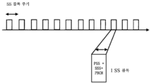
셀 동기화 및 랜덤 액세스(random access)(RA) 프로세스를 포함하는, 무선 통신 시스템 내의 기지국과 단말 디바이스 사이의 예시적인 초기 접속/동기화 프로세스가 도 1과 관련하여 먼저 설명된다. 일반적으로, 무선 통신 시스템은 복수의 기지국을 포함할 수 있고, 그것들 각각은 개별 커버리지 영역(예를 들어, 셀) 내의 수 개의 단말 디바이스를 서빙할 수 있다. 단말 디바이스(110)와 기지국(120) 사이의 예시적인 셀 동기화 및 RA 프로세스가 도 1에 도시되며, 단말 디바이스(110)는 기지국(120)에 의해 서빙되는 수 개의 단말 디바이스 중 하나이다. 이러한 프로세스는 또한 무선 통신 시스템 내의 임의의 단말 디바이스에 적용가능할 수 있다.An exemplary initial connection/synchronization process between a terminal device and a base station in a wireless communication system, including a cell synchronization and random access (RA) process, is first described with respect to FIG. 1. In general, a wireless communication system may include a plurality of base stations, each of which may serve several terminal devices within a separate coverage area (eg, cell). An exemplary cell synchronization and RA process between the terminal device 110 and the base station 120 is shown in FIG. 1, and the terminal device 110 is one of several terminal devices served by the base station 120. This process may also be applicable to any terminal device in a wireless communication system.
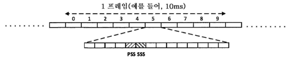
우선, 단말 디바이스(110)는, 부팅 시에, 또는 기지국(120)에 핸드오버되기 위해, 셀 검색을 수행할 필요가 있다. 셀 검색의 목적 중 하나는 단말 디바이스(110)가 기지국(120)의 셀 프레임 타이밍을 획득하여, 다운링크 프레임의 시작 위치를 도출할 수 있게 하는 것이다. 한편, 기지국(120)은 단말 디바이스(110)가 셀 프레임 타이밍을 획득할 수 있도록 동기화 신호(101)를 전송하고, 기지국(120)은 예를 들어 주기적으로 동기화 신호 전송을 수행할 수 있다. 일반적으로, 동기화 시퀀스는 동기화 신호에 포함될 수 있고, 동기화 시퀀스가 그로부터 선택되는 동기화 시퀀스 세트는 기지국과 단말 디바이스 둘 다에게 알려진다. LTE 시스템에서, 예를 들어, 동기화 신호는 1차 동기화 신호(Primary Synchronization Signal)(PSS) 및 2차 동기화 신호(Secondary Synchronization Signal)(SSS)를 포함한다. 일례에서, PSS는 길이 63의 Zadoff-Chu 시퀀스일 수 있고, SSS는 길이 62의 시퀀스일 수 있으며 길이 31의 2개의 캐스케이드 M-시퀀스(cascade M-sequences)로부터 도출될 수 있다. 더욱이, 동기화 신호는 소정의 시간 주기 또는 시간 패턴으로 전송될 수 있고, 예를 들어, 동기화 신호는 다운링크 프레임에서 고정된 위치들(예를 들어, 고정된 서브프레임들, 시간 슬롯들, 및 심볼 위치들)에서 전송될 수 있다. 이러한 방식으로, 단말 디바이스(110)는 단일 서브프레임 내의 수신 신호와 공지된 동기화 시퀀스 세트 내의 동기화 시퀀스들에 대한 상관 동작을 캐리어 중심에서 하나씩 수행할 수 있고, 다음으로 상관의 피크 위치는 다운링크 프레임 내의 동기화 신호의 위치에 대응하며, 그에 의해 단말 디바이스(110)는 다운링크 셀 동기화를 획득할 수 있다.First, the terminal device 110 needs to perform a cell search at the time of booting or to be handed over to the base station 120. One of the purposes of cell search is to enable the terminal device 110 to obtain the cell frame timing of the base station 120 and derive the start position of the downlink frame. On the other hand, the base station 120 transmits the synchronization signal 101 so that the terminal device 110 can obtain the cell frame timing, and the base station 120 may periodically perform synchronization signal transmission, for example. In general, the synchronization sequence may be included in the synchronization signal, and the set of synchronization sequences from which the synchronization sequence is selected is known to both the base station and the terminal device. In an LTE system, for example, the synchronization signal includes a Primary Synchronization Signal (PSS) and a Secondary Synchronization Signal (SSS). In one example, the PSS may be a length 63 Zadoff-Chu sequence, and the SSS may be a length 62 sequence and may be derived from two cascade M-sequences of length 31. Moreover, the synchronization signal can be transmitted in a predetermined time period or time pattern, for example, the synchronization signal can be transmitted at fixed positions (e.g., fixed subframes, time slots, and symbol) in the downlink frame. Locations). In this way, the terminal device 110 can perform a correlation operation for the received signal in a single subframe and the synchronization sequences in the known synchronization sequence set one by one at the carrier center, and then the peak position of the correlation is the downlink frame Corresponding to the location of the synchronization signal within, whereby the terminal device 110 can obtain downlink cell synchronization.
다운링크 셀 동기화를 획득한 후, 단말 디바이스(110)는 다운링크 프레임의 적절한 위치에서 셀의 시스템 정보를 수신할 수 있다. 시스템 정보는 주기적으로 브로드캐스트를 위한 채널(예를 들어, 브로드캐스트 채널 PBCH, 공유 채널 PDSCH 등)을 통해 기지국(120)에 의해 브로드캐스트될 수 있고, 기지국(120)에 액세스하는 단말 디바이스(110)에 필요한 정보, 예컨대 RA 관련 정보를 포함할 수 있다.After obtaining downlink cell synchronization, the terminal device 110 may receive the system information of the cell at an appropriate position in the downlink frame. System information may be periodically broadcast by the base station 120 through a channel for broadcast (eg, a broadcast channel PBCH, a shared channel PDSCH, etc.), and the terminal device 110 accessing the base station 120 ), for example, RA-related information.
그 후, 업링크 셀 동기화를 획득하기 위해, 단말 디바이스(110)는 RA 프로세스를 수행할 필요가 있다. 예시적인 RA 프로세스는 다음과 같이 동작한다. 102에서, 단말 디바이스(110)는 RA 프리앰블(예를 들어, MSG-1에 포함됨)을 기지국(120)에 전송함으로써, 기지국(120)에게 그것의 액세스 동작을 통지할 수 있다. RA 프리앰블의 전송은 기지국(120)이 단말 디바이스의 업링크 타이밍 어드밴스(TA)를 추정할 수 있게 한다. 103에서, 기지국(120)은 RA 응답(예를 들어, MSG-2 포함됨)을 단말 디바이스(110)에 전송함으로써 상기 타이밍 어드밴스를 단말 디바이스(110)에게 통지할 수 있다. 단말 디바이스(110)는 이러한 타이밍 어드밴스에 의해 업링크 셀 동기화를 구현할 수 있다. RA 응답은 또한 업링크 자원의 정보를 포함할 수 있고, 단말 디바이스(110)는 이하의 동작(104)에서 업링크 자원을 사용할 수 있다. 경합 기반 RA 프로세스에 대해, 104에서, 단말 디바이스(110)는 상기 스케줄링된 업링크 자원들을 통해 단말 디바이스 식별 및 아마도 다른 정보(예를 들어, MSG-3에 포함됨)를 전송할 수 있다. 기지국(120)은 단말 디바이스 식별에 의해 경합 해결 결과를 결정할 수 있다. 105에서, 기지국(120)은 경합 해결 결과(예를 들어, MSG-4에 포함됨)를 단말 디바이스(110)에 알릴 수 있다. 이 때, 경합에 성공하는 경우, 단말 디바이스(110)는 기지국(120)에 성공적으로 액세스하고, RA 프로세스가 종료하며; 그렇지 않으면, 단말 디바이스(110)는 RA 프로세스의 동작들(102 내지 105)을 반복할 필요가 있다. 일례에서, RA 프로세스가 성공한 후, 단말 디바이스와 기지국 사이의 초기 접속/동기화 프로세스가 완료된 것으로 고려될 수 있고, 단말 디바이스는 기지국과의 후속 통신을 수행할 수 있다.Then, in order to obtain uplink cell synchronization, the terminal device 110 needs to perform an RA process. The exemplary RA process operates as follows. At 102, the terminal device 110 may notify the base station 120 of its access operation by sending an RA preamble (eg, included in MSG-1) to the base station 120. Transmission of the RA preamble allows the base station 120 to estimate the uplink timing advance (TA) of the terminal device. At 103, the base station 120 may notify the terminal device 110 of the timing advance by sending an RA response (eg, MSG-2 included) to the terminal device 110. The terminal device 110 may implement uplink cell synchronization by this timing advance. The RA response may also include information of the uplink resource, and the terminal device 110 may use the uplink resource in operation 104 below. For the contention-based RA process, at 104, the terminal device 110 may transmit the terminal device identification and possibly other information (eg, included in MSG-3) via the scheduled uplink resources. The base station 120 may determine a contention resolution result by identification of the terminal device. At 105, the base station 120 may inform the terminal device 110 of the contention resolution result (eg, included in MSG-4). At this time, if contention is successful, the terminal device 110 successfully accesses the base station 120, and the RA process ends; Otherwise, the terminal device 110 needs to repeat the operations 102-105 of the RA process. In one example, after the RA process is successful, it may be considered that the initial connection/synchronization process between the terminal device and the base station is complete, and the terminal device can perform subsequent communication with the base station.
빔 형성 및 빔 스캐닝의 개요Overview of beam shaping and beam scanning
빔 형성은 일반적으로 안테나 전송 및/또는 수신의 강한 지향성을 고려하여, 각각의 전송 빔 및/또는 수신 빔이 특정 방향 및 빔 커버리지를 가리키도록 제한되며, 각각의 빔의 커버리지는 전폭 빔(full-width beam)보다 좁지만 빔의 이득은 증가하게 하는 것을 지칭한다. 이러한 전송 빔들 및/또는 수신 빔들은 대략 전폭 빔으로 결합될 수 있다. 전폭 빔은 빔 형성이 없는 빔을 지칭할 수 있는데, 즉 그것의 빔 폭은 빔 형성 처리에 의해 좁혀지지 않는다. 예를 들어, 무지향성 안테나의 빔은 전폭 빔으로 고려될 수 있다. 물리적 구현의 일부 경우들에서, 전송 단의 통신 디바이스는 복수의 안테나 및 그들의 위상 시프터들에 각각 접속되는 복수의 무선 주파수 링크를 갖고, 각각의 무선 주파수 링크 상의 신호들은 상이한 위상들을 갖는 복수의 안테나에 의해 공기 내로 중첩하여 전송되어 전송 빔을 형성한다. 전송 단의 통신 디바이스의 제어 유닛은 타겟 전송 빔 방향에 따라 대응하는 복수의 안테나의 위상 값들을 결정하고, 개별 위상 시프터들을 구성함으로써, 전송 빔 형성을 제어한다. 따라서, 수신 단의 통신 디바이스는 복수의 안테나 및 그들의 위상 시프터들에 각각 접속되는 하나 이상의 무선 주파수 링크를 갖고, 공기 중의 무선 신호들은 상이한 위상들을 갖는 복수의 안테나에 의해 RF 링크로 중첩하여 수신되어 수신 빔을 형성한다. 수신 단의 통신 디바이스의 제어 유닛은 타겟 수신 빔 방향에 따라 대응하는 복수의 안테나의 위상 값들을 결정하고, 개별 위상 시프터들을 구성함으로써, 수신 빔 형성을 제어한다. 일부 예들에서, 통신 디바이스들의 제어 유닛들은 미리 결정된 코드북에 따라 각각의 무선 주파수 링크의 복수의 안테나의 위상 시프터들을 구성한다. 코드북은 복수의 코드워드를 포함하며, 각각의 코드워드는 위상 시프터들의 위상 조합을 나타내는 하나의 빔 방향에 대응한다.In general, beam formation is limited to point to a specific direction and beam coverage in consideration of the strong directivity of antenna transmission and/or reception, and the coverage of each beam is a full-width beam (full -width beam), but refers to increasing the gain of the beam. These transmit beams and/or receive beams may be combined into an approximately full-width beam. The full-width beam may refer to a beam without beam forming, ie its beam width is not narrowed by the beam forming process. For example, the beam of the omni-directional antenna may be considered a full-width beam. In some cases of physical implementation, the communication device at the transmitting end has a plurality of antennas and a plurality of radio frequency links each connected to their phase shifters, and the signals on each radio frequency link are to a plurality of antennas having different phases. It is superimposed and transmitted into the air to form a transmission beam. The control unit of the communication device at the transmitting end determines the phase values of the corresponding plurality of antennas according to the target transmission beam direction, and controls the transmission beam formation by configuring individual phase shifters. Accordingly, the communication device at the receiving end has a plurality of antennas and one or more radio frequency links each connected to their phase shifters, and radio signals in the air are received by overlapping an RF link by a plurality of antennas having different phases to be received. Form a beam. The control unit of the communication device at the receiving end determines the phase values of a plurality of antennas corresponding to the target receiving beam direction, and configures individual phase shifters to control the receiving beam formation. In some examples, the control units of the communication devices configure phase shifters of a plurality of antennas of each radio frequency link according to the predetermined codebook. The codebook includes a plurality of codewords, and each codeword corresponds to one beam direction indicating a phase combination of phase shifters.
빔 형성에서, 안테나 전송 및/또는 수신의 강한 지향성으로 인해, 빔 형성 이득이 달성될 것을 보장하기 위해, 다운링크 또는 업링크에서 쌍을 이룬 전송 및 수신 빔이 필요하다. 따라서, 다운링크 또는 업링크에서 이와 같이 쌍을 이룬 전송 및 수신 빔들이 수집되고 유지될 수 있는데, 즉 빔 관리가 수행된다. 빔 관리는 두 가지 중요한 양태, 즉 빔 스캐닝과 스캐닝 결과 상호작용을 수반한다. 빔 스캐닝은 전송 빔 스캔 및 수신 빔 스캔을 포함할 수 있고, 이는 소정의 공간 영역을 커버하도록 일정 기간에 걸쳐 미리 결정된 방식으로 상이한 빔들을 각각 전송 및 수신하고, 그에 의해 소정의 방위각 공간 영역에 적합한 전송 및 수신 빔을 찾는 것을 지칭한다. 다운링크를 예로 들면, 기지국의 특정 방위에 통상적으로 하나의 단말 디바이스가 위치되기 때문에, 통상적으로, 단말 디바이스와의 통신에 적합한 기지국 측에서의 단 하나의(또는 그보다 많은) 특정 전송 빔들이 존재한다. 또한, 통상적으로, 단말 측에서의 특정 전송 빔과 짝을 이루는 하나의(또는 그보다 많은) 수신 빔이 존재한다. 단말 디바이스는 스캔 결과 보고를 사용하여 그것과 짝을 이루는 기지국 측의 특정 전송 빔을 기지국에 보고할 수 있다. 동기화 신호들의 송수신에서, 일치하는 전송 및 수신 빔의 쌍은 동기화 신호가 소정의 임계 레벨에 부합하도록 수신될 때 동기화 시퀀스 상관 동작들의 상관 결과들을 야기하는 전송 및 수신 빔 쌍들을 지칭할 수 있다. 데이터의 후속 송수신에서, 전송 및 수신 빔들의 쌍을 통한 통신 품질[예를 들어, 수신 신호 강도(예컨대, RSRP), 신호 대 간섭 및 잡음비(예컨대, CQI), 비트 에러 레이트(예컨대, BER, BLER) 등]은 또한 소정의 통신 품질 요구들에 부합할 수 있다.In beamforming, due to the strong directivity of antenna transmission and/or reception, paired transmit and receive beams in the downlink or uplink are needed to ensure that a beamforming gain is achieved. Accordingly, in the downlink or the uplink, such paired transmit and receive beams can be collected and maintained, that is, beam management is performed. Beam management involves two important aspects: beam scanning and scanning result interaction. Beam scanning may include a transmit beam scan and a receive beam scan, which respectively transmit and receive different beams in a predetermined manner over a period of time to cover a predetermined spatial area, thereby suitable for a predetermined azimuth spatial area. Refers to finding transmit and receive beams. Taking the downlink as an example, since one terminal device is typically located in a specific orientation of the base station, there is typically only one (or more) specific transmission beams at the base station side suitable for communication with the terminal device. In addition, typically, there is one (or more) reception beams paired with a specific transmission beam at the terminal side. The terminal device may report a specific transmission beam of a base station paired with it to the base station by using the scan result report. In the transmission and reception of synchronization signals, a pair of matching transmit and receive beams may refer to pairs of transmit and receive beams that cause correlation results of synchronization sequence correlation operations when the synchronization signal is received to meet a predetermined threshold level. In subsequent transmission and reception of data, communication quality (e.g., received signal strength (e.g., RSRP), signal to interference and noise ratio (e.g., CQI), bit error rate (e.g., BER, BLER) over a pair of transmit and receive beams ) Etc] may also meet certain communication quality requirements.
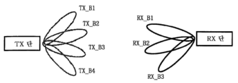
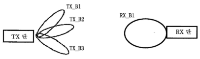
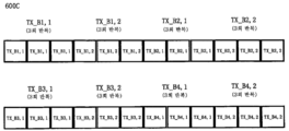
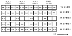
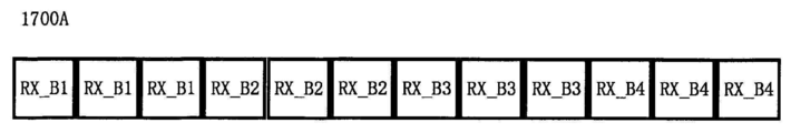
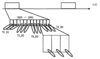
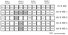
이하에서는, 빔 형성 기술에서의 빔 스캐닝이 도 2a-도 2d와 함께 설명된다. 빔 형성에서, 전송 단은 복수의 전송 빔을 통해 전송 빔 스캐닝을 수행할 수 있다. 도 2a의 예에서, 전송 단은 4개의 전송 빔을 제공받고, 도 2b의 예에서, 전송 단은 3개의 전송 빔을 제공받는다. 수신 단은 구성 또는 적용 요건들에 따라 수신 빔 형성을 사용할 수도 있고 사용하지 않을 수도 있다. 도 2a의 예에서, 수신 단은 수신 빔 형성을 사용하고, 3개의 수신 빔을 통해 수신 빔 스캐닝을 수행한다. 도 2b의 예에서, 수신 단은 수신 빔 형성을 사용하지 않고, 하나의 전폭 수신 빔만을 제공받는다. 빔 형성에서, 전송 단 및/또는 수신 단은 또한 제1 레벨 전송 빔들[대강의 전송 빔들(coarse transmit beams)이라고도 칭해짐] 및 제2 레벨 전송 빔들[미세한 전송 빔들(fine transmit beams)이라고도 칭해짐]과 같은 계층적 전송 빔들을 제공받을 수 있다. 도 2c의 예에서, 전송 단은 3개의 제1 레벨 전송 빔(즉, TX_B1 내지 TX_B3)을 제공받으며, 각각의 제1 레벨 전송 빔은 2개의 제2 레벨 전송 빔을 더 제공받는다(예를 들어, TX_B1의 2개의 미세한 전송 빔은 TX_B1, 1 및 TX_B1, 2이고, 나머지는 유사하다). 도 2d의 예에서, 전송 단 및 수신 단 둘 다가 계층적 전송 빔을 제공받을 수 있다. 도 2d에서, 전송 단의 전송 빔들은 도 2c의 전송 빔들과 유사하고, 수신 단은 3개의 제1 레벨 수신 빔(즉, RX_B1 내지 RX_B3)을 제공받으며, 각각의 제1 레벨 수신 빔은 2개의 제2 레벨 수신 빔을 더 제공받는다(예를 들어, RX_B1의 2개의 미세한 전송 빔은 RX_B1, 1 및 RX_B1, 2이고, 나머지는 유사하다). 도 2c 및 도 2d에 도시된 바와 같이, 대강의 전송 빔의 빔 폭은 미세한 전송 빔의 빔 폭보다 넓을 수 있고, 미세한 전송 빔의 이득은 대강의 전송 빔의 이득보다 클 수 있다.In the following, beam scanning in the beam forming technique is described together with FIGS. 2A-2D. In beamforming, the transmission end may perform transmission beam scanning through a plurality of transmission beams. In the example of FIG. 2A, the transmitting end is provided with 4 transmission beams, and in the example of FIG. 2B, the transmitting end is provided with 3 transmission beams. The receiving end may or may not use receive beamforming depending on configuration or application requirements. In the example of FIG. 2A, the receiving end uses receive beamforming and performs receive beam scanning through three receive beams. In the example of FIG. 2B, the receiving end does not use receiving beamforming and receives only one full-width receiving beam. In beamforming, the transmitting end and/or the receiving end are also referred to as first level transmit beams (also referred to as coarse transmit beams) and second level transmit beams (also referred to as fine transmit beams). ] Can be provided with hierarchical transmission beams. In the example of FIG. 2C, the transmission end is provided with three first level transmission beams (ie, TX_B1 to TX_B3), and each of the first level transmission beams is further provided with two second level transmission beams (e.g., , TX_B1 two fine transmission beams are TX_B1, 1 and TX_B1, 2, and the rest are similar). In the example of FIG. 2D, both a transmitting end and a receiving end may receive a hierarchical transmission beam. In FIG. 2D, the transmission beams of the transmission end are similar to the transmission beams of FIG. 2C, and the reception end is provided with three first level reception beams (i.e., RX_B1 to RX_B3), and each of the first level reception beams has two A second level reception beam is further provided (for example, the two fine transmission beams of RX_B1 are RX_B1, 1 and RX_B1, 2, and the rest are similar). As shown in FIGS. 2C and 2D, the beam width of the approximate transmission beam may be wider than that of the fine transmission beam, and the gain of the fine transmission beam may be greater than the gain of the approximate transmission beam.
빔 스캐닝 프로세스에서, 전송 단은 전송 빔 전송을 하나씩 수행할 수 있다(즉, 전송 빔 스캐닝). 예를 들어, 수신 단의 상황들을 고려하여, 각각의 전송 빔 은 1회 전송될 수 있거나 복수 회 반복적으로 전송될 수 있다. 일치하는 전송 및 수신 빔 쌍들을 결정하기 위해, 각각의 전송 빔의 전송은 수신 단에서 수신 빔들을 사용하여 하나씩 수신될 수 있다(즉, 수신 빔 스캐닝). 예를 들어, 도 2a의 예에서, 전송 단은 먼저 전송 빔 TX_B1을 사용하여 3회 반복 전송할 수 있다. 따라서, 수신 단은 수신 빔들 RX_B1 내지 RX_B3을 하나씩 사용하여 대응하는 하나의 전송을 수신할 수 있고, 동기화 시퀀스들의 개별 상관을 도출할 수 있다. 다음으로, 전송 단은 전송 빔 TX_B2를 사용하여 3회 반복 전송할 수 있고, 수신 단은 수신 빔들 RX_B1 내지 RX_B3를 하나씩 사용하여 대응하는 하나의 전송을 수신하고 동기화 시퀀스들의 개별 상관을 도출할 수 있다. 전송 단이 전송 빔들 TX_B3 및 TX_B4를 사용하여 반복 전송한 후, 수신 단은 동기화 시퀀스들의 도출된 상관에 기초하여 일치하는 전송 및 수신 빔 쌍을 결정할 수 있다. 따라서, 전송 단과 수신 단 사이의 후속 통신은 이러한 전송 및 수신 빔 쌍을 사용하여 수행될 수 있다. 상기 예에서의 각각의 전송 빔의 반복 전송 횟수는 수신 빔의 수의 정수 배일 수 있다. 수신 단이 복수의 무선 주파수 링크를 가져서, 복수의 수신 빔이 수신을 위해 동시에 사용될 수 있는 경우에서, 전송 단은 각각의 전송 빔을 반복적으로 전송하지 않아도 되며, TX_B1 내지 TX_B4만을 순차적으로 전송한다. 도 2b는 수신 단이 수신 빔 형성을 사용하지 않는 예이다. 도 2b에서, 전송 단에서의 각각의 전송에 대해, 단말 디바이스는 전폭 수신 빔을 사용하여 수신하고, 개별 동기화 시퀀스 상관을 결정하여 전폭 수신 빔에 일치하는 전송 빔을 결정한다. 따라서, 전송 단과 수신 단 사이의 후속 통신들에서, 전송 단은 결정된 전송 빔을 사용하여 통신할 것이다.In the beam scanning process, the transmission end may perform transmission beam transmission one by one (ie, transmission beam scanning). For example, in consideration of the conditions of the receiving end, each transmission beam may be transmitted once or may be repeatedly transmitted a plurality of times. In order to determine the matching transmit and receive beam pairs, the transmission of each transmit beam may be received one by one using receive beams at the receiving end (ie, receive beam scanning). For example, in the example of FIG. 2A, the transmitting end may transmit repeatedly 3 times using the transmission beam TX_B1 first. Accordingly, the receiving end can receive a corresponding transmission by using the reception beams RX_B1 to RX_B3 one by one, and can derive individual correlations of synchronization sequences. Next, the transmitting end may repeatedly transmit three times using the transmit beam TX_B2, and the receiving end may receive one corresponding transmission using the receive beams RX_B1 to RX_B3 one by one and derive individual correlations of synchronization sequences. After the transmitting end repeatedly transmits using the transmit beams TX_B3 and TX_B4, the receiving end may determine a matching transmit and receive beam pair based on the derived correlation of the synchronization sequences. Thus, subsequent communication between the transmitting end and the receiving end can be performed using this transmit and receive beam pair. In the above example, the number of repeated transmissions of each transmission beam may be an integer multiple of the number of reception beams. In a case where a receiving end has a plurality of radio frequency links and a plurality of receive beams can be used simultaneously for reception, the transmitting end does not need to repeatedly transmit each transmit beam, and transmits only TX_B1 to TX_B4 sequentially. 2B is an example in which the receiving end does not use receive beamforming. In FIG. 2B, for each transmission at the transmitting end, the terminal device receives using a full-width reception beam, and determines a transmission beam that matches the full-width reception beam by determining individual synchronization sequence correlation. Thus, in subsequent communications between the transmitting end and the receiving end, the transmitting end will communicate using the determined transmission beam.
도 2c의 계층적 전송 빔들의 경우에서, 일치하는 제1 레벨 전송 빔이 먼저 결정될 수 있고, 그에 후속하여, 일치하는 제1 레벨 전송 빔 아래의 일치하는 제2 레벨 전송 빔이 결정된다. 예를 들어, 전송 단은 먼저 제1 레벨 전송 빔 스캐닝을 수행할 수 있고, 수신 단은 위에서 설명된 것과 유사한 방식으로 제1 레벨 전송 빔 일치를 결정할 수 있다. 전송 단이 일치하는 제1 레벨 전송 빔 아래의 제2 레벨 전송 빔들을 통해 빔 스캐닝을 수행할 때, 수신 단은 마찬가지로 그에 일치하는 제2 레벨 전송 빔을 결정할 수 있다. 따라서, 제2 레벨 전송 빔 및 일치하는 수신 빔은 궁극적으로 후속 통신에서의 사용을 위한 일치하는 전송 및 수신 빔 쌍으로서 결정된다. 예시적인 구현예에 따르면, 제2 레벨 전송 빔들을 통해 빔 스캐닝이 수행되는 경우, 수신 단은 모든 수신 빔을 대신하여, 제1 레벨 전송 빔들을 통해 빔 스캐닝이 수행될 때 결정된 일치하는 수신 빔을 수신 및 결정을 위한 수신 빔으로서 직접 사용할 수 있고, 그에 의해 빔 스캐닝 오버헤드를 감소시킨다.In the case of the hierarchical transmission beams of Fig. 2C, a matching first level transmission beam may be determined first, and subsequently, a matching second level transmission beam below the matching first level transmission beam is determined. For example, the transmitting end may first perform first-level transmission beam scanning, and the receiving end may determine first-level transmission beam matching in a manner similar to that described above. When the transmission end performs beam scanning through the second level transmission beams below the matching first level transmission beam, the reception end may likewise determine a second level transmission beam corresponding thereto. Thus, the second level transmit beam and matched receive beam are ultimately determined as matched transmit and receive beam pairs for use in subsequent communications. According to an exemplary embodiment, when beam scanning is performed through the second level transmission beams, the receiving end replaces all the reception beams with a matching reception beam determined when the beam scanning is performed through the first level transmission beams. It can be used directly as a receive beam for reception and determination, thereby reducing beam scanning overhead.
도 2d에서 전송 빔들 및 수신 빔들이 둘 다 계층적인 경우에서, 빔 스캐닝에서, 전송 단은 먼저 제1 레벨 전송 빔 스캐닝을 수행할 수 있고, 수신 단은 대응하는 제1 레벨 수신 빔들을 사용하여 수신될 수 있고, 그에 의해, 위에서 설명된 것과 유사한 방식으로 일치하는 제1 레벨 전송 빔 및 제1 레벨 수신 빔을 결정한다. 전송 단이 일치하는 제1 레벨 전송 빔 아래의 제2 레벨 전송 빔들을 통해 빔 스캐닝을 수행할 때, 수신 단에서 대응하는 일치하는 제1 레벨 수신 빔 아래의 제2 레벨 수신 빔들을 사용하여 수신이 이루어질 수 있고, 따라서 일치하는 제2 레벨 전송 빔 및 제2 레벨 수신 빔은 후속 통신에서의 사용을 위한 일치하는 전송 및 수신 빔 쌍으로서 위에서 설명된 것과 유사한 방식으로 결정된다.In the case where both the transmit beams and the receive beams are hierarchical in FIG. 2D, in beam scanning, the transmitting end may first perform first-level transmit beam scanning, and the receiving end receives using corresponding first-level receive beams. And thereby determine a matching first level transmit beam and first level receive beam in a manner similar to that described above. When the transmitting end performs beam scanning through the second level transmit beams under the matched first-level transmit beam, the receiving end performs reception using the second level receive beams under the corresponding first-level receive beam. And thus a matched second level transmit beam and second level receive beam are determined in a manner similar to that described above as a matched transmit and receive beam pair for use in subsequent communications.
다운링크 통신에서, 전송 단은 기지국(120)에 대응할 수 있고, 수신 단은 단말 디바이스(110)에 대응할 수 있다는 점을 이해해야 한다. 업링크 통신에서, 전송 단은 단말 디바이스(110)에 대응할 수 있고, 수신 단은 기지국(120)에 대응할 수 있다. 본 명세서의 실시예에서, 업링크에서의 일치하는 전송 및 수신 빔이 다운링크에서의 일치하는 수신 및 전송 빔에 대응하는 경우(예를 들어, 동일한 경우), 업링크 및 다운링크에서의 전송 및 수신 빔 쌍은 대칭성을 갖는다고 칭해진다. 대칭성은 단말 디바이스(110)와의 일치 측면에서, 기지국의 전송 빔은 기지국(120)의 수신 빔에 대응하고, 일치하는 대응하는 수신 빔(또는 전송 빔)은 기지국 측의 일치하는 전송 빔(또는 수신 빔)에 따라 결정될 수 있음을 의미한다. 기지국(120)과의 일치의 측면에서, 단말 디바이스(110) 측에서의 상황은 유사하다.In downlink communication, it should be understood that the transmitting end may correspond to the base station 120 and the receiving end may correspond to the terminal device 110. In uplink communication, the transmitting end may correspond to the terminal device 110 and the receiving end may correspond to the base station 120. In an embodiment of the present specification, when the matched transmit and receive beams in the uplink correspond to the matched receive and transmit beams in the downlink (e.g., the same case), the transmits in the uplink and the downlink, and The receive beam pair is said to have symmetry. Symmetry is in terms of coincidence with the terminal device 110, the transmission beam of the base station corresponds to the reception beam of the base station 120, and the corresponding corresponding reception beam (or transmission beam) corresponds to the transmission beam (or reception) of the base station. It means that it can be determined according to the beam). In terms of matching with the base station 120, the situation at the terminal device 110 side is similar.
동기화 신호 송수신에서의 빔 형성 기술의 적용Application of beamforming technology in transmission and reception of synchronization signals
이하에서는, 위에서 언급된 동기화 신호들의 송수신에서의 빔 형성 기술의 적용이 간단히 설명될 것이다. 무선 통신 분야에서, 데이터 신호들을 전송하기 위해 빔 형성 기술들이 사용되어 왔다. 본 명세서의 실시예에 따르면, 빔 형성은 동기화 신호들을 전송하기 위해 사용될 수 있다. 예를 들어, 기지국(120)은 단말 디바이스(110)가 다운링크 동기화 및 RA 프로세스를 적절하게 수행할 것을 보장하도록 동기화 신호의 손실을 보상하기 위해 전송 빔 형성을 사용하여 동기화 신호들을 전송할 수 있다. 본 개시내용에 따른 기술적 해법은 수백 MHz 내지 수 GHz 범위의 종래의 무선 주파수 통신 대역들을 포함하는 다양한 통신 주파수 대역들에서 사용될 수 있다. 예를 들어 26GHz, 60GHz 또는 그보다 높은 대역들을 사용하여 무선 통신 시스템들의 주파수 대역들이 증가함에 따라, 무선 채널들은 저주파수 대역들(예를 들어, 2GHz)에 비해 경로 손실들, 대기 흡수 손실 등과 같은 부정적인 영향들을 더 많이 경험할 것이다. 따라서, 본 개시내용에 따른 기술적 해법은 고주파수 대역(예를 들어, 밀리미터 파) 통신에 동일하게 적용가능하며, 그에 대해 훨씬 더 중요하다.In the following, the application of the beamforming technique in the transmission and reception of the synchronization signals mentioned above will be briefly described. In the field of wireless communication, beamforming techniques have been used to transmit data signals. According to an embodiment of the present specification, beamforming may be used to transmit synchronization signals. For example, the base station 120 may transmit synchronization signals using transmit beamforming to compensate for the loss of the synchronization signal to ensure that the terminal device 110 performs the downlink synchronization and RA process properly. The technical solution according to the present disclosure can be used in a variety of communication frequency bands, including conventional radio frequency communication bands in the range of several hundred MHz to several GHz. For example, as the frequency bands of wireless communication systems increase using bands of 26 GHz, 60 GHz or higher, radio channels have negative effects such as path losses, atmospheric absorption loss, etc. compared to low frequency bands (e.g., 2 GHz). You will experience more to hear. Thus, the technical solution according to the present disclosure is equally applicable to high frequency band (eg, millimeter wave) communication, and is even more important for it.
본 명세서의 일부 실시예들에서, 동기화 신호의 전송은 동기화 신호를 전송하기 위해 사용되는 전송 빔의 정보를 나타낼 수 있고, 그에 의해 단말 디바이스는 동기화 신호를 수신함으로써 전송 빔의 정보를 획득할 수 있어서, 후속 데이터 전송 동안의 빔 스캐닝이 단순화되고 가속화된다. 본 명세서의 일부 실시예들에 따르면, 동기화 신호는 기지국에 의해 전송 빔 구성에 기초하는 상이한 전송 빔들을 사용하여 단말 디바이스를 포함하는 복수의 단말 디바이스에 반복 전송될 수 있고, 동기화 신호는 아래에 설명되는 바와 같이, 동기화 신호를 전송하기 위해 사용되는 전송 빔의 정보를 포함할 수 있다. 예를 들어, 동기화 신호들을 전송하기 위해 빔 형성 기술을 사용하는 일부 실시예들에서, 기지국(120)이 복수의 상이한 전송 빔에서 동기화 신호들을 반복 전송할 것이라는 점을 고려하여, 다운링크 프레임에서의 동기화 신호 시간 윈도우들은 나중에 상세하게 설명되는 바와 같이 재설계된다. 전송 빔 스캐닝에서의 복수의 전송 빔의 반복 패턴은 전송 빔 구성에 의해 표현될 수 있고, 동기화 신호는 전송 빔 구성에 기초하여 전송될 수 있다.In some embodiments of the present specification, transmission of a synchronization signal may indicate information of a transmission beam used to transmit a synchronization signal, whereby a terminal device can obtain information of a transmission beam by receiving a synchronization signal. , Beam scanning during subsequent data transmission is simplified and accelerated. According to some embodiments of the present specification, the synchronization signal may be repeatedly transmitted by the base station to a plurality of terminal devices including the terminal device using different transmission beams based on the transmission beam configuration, and the synchronization signal is described below. As described above, information on a transmission beam used to transmit a synchronization signal may be included. For example, in some embodiments using a beamforming technique to transmit synchronization signals, taking into account that the base station 120 will repeatedly transmit synchronization signals in a plurality of different transmission beams, synchronization in the downlink frame The signal time windows are redesigned as described in detail later. A repetition pattern of a plurality of transmission beams in transmission beam scanning may be expressed by a transmission beam configuration, and a synchronization signal may be transmitted based on a transmission beam configuration.
단말 디바이스는 다양한 방식으로 동기화 신호를 수신할 수 있다. 동기화 신호를 수신하면, 단말 디바이스는 본 개시내용에서 이하에 설명되는 방식들 및 임의의 다른 방식들을 포함하는 임의의 적절한 방식들로, 적어도 단말 디바이스와 일치하는 기지국의 전송 빔을 결정할 수 있고, 일치하는 전송 빔을 기지국에 피드백할 수 있다. 적어도, 기지국의 일치하는 전송 빔은 기지국과 단말 디바이스 사이의 후속 통신(RA 프로세스 및 데이터 송수신 프로세스를 포함함)을 위해 사용될 수 있다.The terminal device can receive the synchronization signal in various ways. Upon receiving the synchronization signal, the terminal device can determine the transmission beam of the base station that matches at least the terminal device in any suitable manners, including the manners described below in this disclosure and any other manners, and The transmitted beam can be fed back to the base station. At least, the matching transmission beam of the base station can be used for subsequent communication (including the RA process and the data transmission/reception process) between the base station and the terminal device.
일 실시예에서, 단말 디바이스(110)는 동기화 신호를 수신할 때 수신 빔 형성을 사용할 수 없고, 따라서 고속 동기화와 후속 빔 스캐닝 오버헤드 감소 사이의 절충안에 도달한다. 이 때, 단말 디바이스(110)는 기지국 측에서의 전송 빔들 각각에 의해 전송되는 동기화 신호를 자기 자신의 전폭 빔으로 수신하고, 동기화 신호가 성공적으로 수신될 때 전폭 빔과 일치하는 기지국 측의 전송 빔을 기지국(120)에 피드백하는 것으로 고려될 수 있다. 다른 실시예에서, 대안적으로, 단말 디바이스(110)는 동기화 신호를 수신할 때 수신 빔 형성을 사용할 수 있고, 따라서 고주파수 동기화 신호의 페이딩에 저항하고, 후속 빔 스캐닝 오버헤드를 절약한다. 이 때, 동기화 신호가 성공적으로 수신될 때 일치되는 단말 디바이스 측에서의 수신 빔 및 기지국 측에서의 전송 빔이 결정될 수 있고, 일치하는 전송 빔은 기지국(120)에 피드백될 수 있다. 일치하는 전송 및 수신 빔 쌍은 기지국(120)과 단말 디바이스(110) 사이의 후속 통신들(RA 프로세스들 및 데이터 송수신 프로세스들을 포함함)에 직접적으로 또는 간접적으로 사용될 것이다. 예를 들어, 기지국(120) 및 단말 디바이스(110)는 데이터 송수신을 위한 것과 동일한 빔들을 동기화 신호를 위한 일치하는 전송 빔 및 수신 빔으로서 사용하는데, 즉 동기화 신호와 데이터 신호의 빔 형성 코드북은 동일하다. 다른 예를 들면, 기지국(120) 및 단말 디바이스(110)는 동기화 신호를 위한 일치하는 전송 빔 및 수신 빔을 제1 레벨 빔 쌍으로서 사용하고, 제1 레벨 빔 쌍의 커버리지 범위 내에서 제2 레벨 빔 스캔을 수행하여, 데이터 송수신에서 사용될 더 미세한 수신 및 전송 빔 쌍을 결정하며, 즉 동기화 신호 및 데이터 신호의 빔 형성 코드북들은 상이하고, 데이터 신호의 빔 형성 코드북은 동기화 신호의 빔 형성 코드북의 서브세트이다.In one embodiment, the terminal device 110 cannot use receive beamforming when receiving the synchronization signal, thus reaching a compromise between fast synchronization and subsequent beam scanning overhead reduction. At this time, the terminal device 110 receives the synchronization signal transmitted by each of the transmission beams from the base station as its own full-width beam, and when the synchronization signal is successfully received, the terminal device 110 transmits a transmission beam from the base station side that matches the full-width beam to the base station. It can be considered as feedback to 120. In another embodiment, alternatively, the terminal device 110 may use receive beamforming when receiving the synchronization signal, thus resisting fading of the high frequency synchronization signal and saving subsequent beam scanning overhead. At this time, when the synchronization signal is successfully received, a matching reception beam at the terminal device side and a transmission beam at the base station side may be determined, and the matching transmission beam may be fed back to the base station 120. The matching transmit and receive beam pair will be used directly or indirectly for subsequent communications (including RA processes and data transmission/reception processes) between base station 120 and terminal device 110. For example, the base station 120 and the terminal device 110 use the same beams as those for data transmission and reception as the matching transmission beam and reception beam for the synchronization signal, that is, the beamforming codebook of the synchronization signal and the data signal is the same. Do. For another example, the base station 120 and the terminal device 110 use a matching transmission beam and a reception beam for a synchronization signal as a first level beam pair, and a second level within the coverage range of the first level beam pair. By performing a beam scan, a finer pair of reception and transmission beams to be used in data transmission/reception is determined, that is, the beamforming codebooks of the synchronization signal and the data signal are different, and the beamforming codebook of the data signal is a sub of the beamforming codebook of the synchronization signal. It is a set.
단말 디바이스가 또한 동기화 신호를 수신하기 위해 빔 형성 기술을 사용하는 일부 실시예들에서, 단말 디바이스는 또한 기지국에 의해 동기화 신호를 전송하기 위해 사용되는 전송 빔 구성(예를 들어, 총합하여 얼마나 많은 전송 빔이 존재하는지, 전송 빔 당 반복 횟수)에 기초하여 동기화 신호를 수신하기 위한 단말 디바이스의 수신 빔을 설정할 수 있다. 예를 들어, 단말 디바이스(110)는 수신 빔 스캐닝을 수행할 필요가 있기 때문에, 즉, 동일한 전송 빔을 통해 기지국 측에 의해 전송된 신호들을 수신하기 위해 상이한 수신 빔들을 사용할 필요가 있기 때문에, 단말 디바이스(110)는 기지국(120)의 전송 빔 구성을 알 필요가 있을 수 있다. 일례에서, 기지국(120)의 전송 빔 구성은 단말 디바이스에 미리 알려질 수 있다. 예를 들어, 단말 디바이스는 기지국(120), 및 이중 접속에 의해 빔 형성 송수신을 수행하지 않는 다른 기지국(예를 들어, LTE eNB)의 서비스들을 동시에 획득할 수 있고, 단말 디바이스(110)는 다른 기지국으로부터 기지국(120)의 전송 빔 구성의 정보를 획득할 수 있다. 구체적으로 말하면, 단말 디바이스(110)는 종래의 방식에 따라 다른 기지국(1차 기지국이라고 지칭될 수 있음)에 먼저 액세스하고, 1차 기지국은 예를 들어 Xn 인터페이스를 통해 기지국(120)에게 그것을 2차 기지국으로서 단말 디바이스(110)에 추가할 것을 요청하며, 기지국(120)은 2차 기지국 추가 요청의 확인을 1차 기지국에 피드백하는데, 그것은 기지국(120)의 동기화 신호를 위한 전송 빔 구성의 정보를 포함하고, 또한 일부 예들에서는 RA 구성 정보를 포함할 수 있다. 다음으로, 1차 기지국은 예를 들어 기지국(120)과의 동기화의 완료를 위해 무선 자원 제어 접속 재구성 메시지에 포함된 그러한 정보를 단말 디바이스(110)에 제공한다. 다른 예에서, 단말 디바이스(110)는 기지국(120)에 의해 전송된 동기화 신호로부터 기지국(120)의 전송 빔 구성을 획득할 수 있다. 예를 들어, 단말 디바이스(110)는 동기화 신호의 측정 프로세스에 의해 기지국(120)의 전송 빔 구성을 추정할 수 있다. In some embodiments where the terminal device also uses a beamforming technique to receive the synchronization signal, the terminal device also uses the transmission beam configuration used by the base station to transmit the synchronization signal (e.g., how many transmissions in total). The reception beam of the terminal device for receiving the synchronization signal may be set based on whether the beam exists or the number of repetitions per transmission beam). For example, because the terminal device 110 needs to perform reception beam scanning, that is, because it needs to use different reception beams to receive signals transmitted by the base station side through the same transmission beam, the terminal device 110 The device 110 may need to know the transmission beam configuration of the base station 120. In one example, the transmission beam configuration of the base station 120 may be known in advance to the terminal device. For example, the terminal device may simultaneously acquire services of the base station 120 and another base station (eg, LTE eNB) that does not perform beamforming transmission/reception by dual access, and the terminal device 110 Information on the transmission beam configuration of the base station 120 may be obtained from the base station. Specifically, the terminal device 110 first accesses another base station (which may be referred to as a primary base station) according to a conventional method, and the
빔 스캐닝 결과들의 보고Reporting of beam scanning results
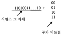
이하에서는, 단말 디바이스에 의한 기지국 측에서의 일치하는 전송 빔의 피드백이 간략히 설명될 것이다. 본 명세서의 실시예에서, 단말 디바이스(110)가 기지국 측에서의 일치하는 전송 빔을 기지국(120)에 피드백할 수 있도록 하기 위해, 소정의 방식으로 전송 빔을 나타낼 필요가 있다. 기지국 측에서의 일치하는 전송 빔은 암시적 또는 명시적 방식으로 나타내어질 수 있고, 그에 의해 빔 스캐닝 결과들을 보고한다. 빔 스캐닝 결과들의 이러한 보고는 단말 디바이스에 의해 수행되는 RA 프로세스에 포함될 수 있다. 물론, 일부 실시예들에 따르면, 기지국 측에서의 전송 빔에 관련된 피드백은 RA 프리앰블과는 별도로, 예를 들어 RA 프리앰블 앞 또는 뒤에 전송될 수 있다.In the following, the feedback of the matching transmission beam at the base station side by the terminal device will be briefly described. In the embodiment of the present specification, in order to enable the terminal device 110 to feed back the matching transmission beam at the base station side to the base station 120, it is necessary to indicate the transmission beam in a predetermined manner. The matching transmission beam at the base station side can be indicated in an implicit or explicit manner, thereby reporting the beam scanning results. Such reporting of beam scanning results may be included in the RA process performed by the terminal device. Of course, according to some embodiments, the feedback related to the transmission beam at the base station side may be transmitted separately from the RA preamble, for example, before or after the RA preamble.
본 명세서의 일부 실시예들에 따르면, 단말 디바이스에 의해 RA 프리앰블을 전송하는 것은, 본 명세서에서 아래에 설명되는 바와 같이 단말 디바이스 측에서의 수신 행동과 일치하는 다운링크에서의 기지국 측의 전송 빔을 나타낼 수 있다. 예를 들어, 단말 디바이스가 수신 빔 형성을 사용하는 경우, 단말 디바이스에 의해 RA 프리앰블을 전송하는 것은 다운링크에서 단말 디바이스 측에서의 수신 빔과 일치하는 기지국 측에서의 전송 빔을 나타낼 수 있고; 단말 디바이스가 수신 빔 형성을 사용하지 않는 경우, 단말 디바이스에 의해 RA 프리앰블을 전송하는 것은 다운링크에서 빔 형성을 사용하지 않는 단말 디바이스 측에서의 수신 행동과 일치하는 기지국 측에서의 전송 빔을 나타낼 수 있다.According to some embodiments of the present specification, transmitting the RA preamble by the terminal device may indicate a transmission beam at the base station side in the downlink that matches the reception behavior at the terminal device side, as described below in this specification. have. For example, when the terminal device uses receive beamforming, transmitting the RA preamble by the terminal device may indicate a transmit beam at the base station side that matches the receive beam at the terminal device side in the downlink; When the terminal device does not use reception beamforming, transmitting the RA preamble by the terminal device may indicate a transmission beam at the base station side that matches the reception behavior at the terminal device side that does not use beamforming in the downlink.
일부 실시예들에서, 단말 디바이스(110)는 다운링크에서 단말 디바이스 측에서의 수신 빔과 일치하는 기지국 측에서의 전송 빔을 나타내기 위해, RA 구성 정보에 기초하여 RA 프리앰블을 전송한다. 일부 실시예들에서, RA 구성 정보는 기지국 측에서의 수신 빔과 복수의 RA 시간 윈도우 사이의 대응관계를 포함할 수 있다. 일 실시예에서, 대응관계는 기지국 측에서의 수신 빔들의 복수의 레벨과 복수의 RA 시간 윈도우 사이의 대응관계를 포함할 수 있다. 단말 디바이스(110)는 이러한 대응관계에 기초하여 RA 프리앰블을 전송할 수 있다. 일례에서, 기지국은 특정 시간 윈도우에서 RA 프리앰블을 수신함으로써 기지국 측에서의 대응하는 전송 빔을 식별 할 수 있다. 이것은 기지국 측에서의 일치하는 전송 빔을 암시적인 방식으로 나타내는 것의 일례이다.In some embodiments, the terminal device 110 transmits an RA preamble based on the RA configuration information to indicate a transmission beam at the base station side that matches the received beam at the terminal device side in the downlink. In some embodiments, the RA configuration information may include a correspondence between a reception beam at the base station side and a plurality of RA time windows. In an embodiment, the correspondence may include a correspondence between a plurality of levels of reception beams at the base station side and a plurality of RA time windows. The terminal device 110 may transmit the RA preamble based on this correspondence. In one example, the base station may identify a corresponding transmission beam at the base station side by receiving the RA preamble in a specific time window. This is an example of indicating a matching transmission beam at the base station in an implicit manner.
일부 실시예들에서, 다운링크에서 단말 디바이스 측에서의 수신 빔과 일치하는 기지국 측에서의 전송 빔은 또한 RA 프리앰블에 후속하는 업링크 메시지, 예를 들어 부가 비트 등에 의해 나타날 수 있고, 이것은 명시적인 방식의 일례이다.In some embodiments, the transmit beam at the base station side that matches the receive beam at the terminal device side in the downlink may also be indicated by an uplink message following the RA preamble, for example an additional bit, etc., which is an example of an explicit scheme. .
본 명세서의 실시예에 따른 동기화 신호의 송수신을 주로 개시하는 본 개시내용에 따른 제1 양태는 도 3a 내지 도 14와 관련하여 이하에 설명된다. 일부 실시예들에 따르면, 동기화 신호는 빔 형성에 의해 기지국 측으로부터 단말 디바이스 측으로 전송되고, 단말 디바이스는 동기화 신호를 수신하고, 기지국에 의해 동기화 신호를 전송하기 위해 사용된 전송 빔의 정보를 획득한다. 그 후, 단말 디바이스는 획득된 전송 빔 정보를 다시 기지국에 피드백하고, 그에 의해 기지국은 후속 통신 사용을 위해, 그것이 동기화 신호를 전송하기 위해 사용되는 전송 빔을 피드백으로부터 학습할 수 있다. 일부 실시예에 따르면, 본 개시내용의 제1 양태에 따른 동작들은 기지국 측 및 단말 디바이스 측을 위해 전자 디바이스들에 의해 수행될 수 있다. 본 개시내용의 제1 양태에 따른 동작은 이하에 상세하게 설명될 것이다.A first aspect according to the present disclosure, which mainly discloses transmission and reception of a synchronization signal according to an embodiment of the present specification, will be described below with reference to FIGS. 3A to 14. According to some embodiments, the synchronization signal is transmitted from the base station side to the terminal device side by beamforming, the terminal device receives the synchronization signal, and obtains information of the transmission beam used to transmit the synchronization signal by the base station. . After that, the terminal device feeds back the acquired transmission beam information back to the base station, whereby the base station can learn from the feedback the transmission beam it is used to transmit the synchronization signal for subsequent communication use. According to some embodiments, operations according to the first aspect of the present disclosure may be performed by electronic devices for the base station side and the terminal device side. Operation according to the first aspect of the present disclosure will be described in detail below.
기지국 측을 위한 전자 디바이스의 예Examples of electronic devices for the base station side
도 3a는 본 명세서의 실시예에 따른 기지국 측에 대한 예시적인 전자 디바이스를 도시하며, 여기서 기지국은 다양한 무선 통신 시스템들에서 사용될 수 있다. 도 3a에 도시된 전자 디바이스(300A)는 본 개시내용에 따른 제1 일반적인 양태를 구현하기 위한 다양한 유닛들을 포함할 수 있다. 도 3a에 도시된 바와 같이, 전자 디바이스(300A)는 예를 들어 동기화 신호 전송 유닛(305) 및 피드백 취득 유닛(310)을 포함할 수 있다. 일 구현예에 따르면, 전자 디바이스(300A)는 예를 들어 도 1의 기지국(120)이거나 기지국(120)의 일부일 수 있고, 또는 기지국을 제어하기 위한 디바이스(예를 들어, 기지국 제어기)이거나 기지국을 위한 디바이스 또는 그것의 일부일 수 있다. 기지국에 관련하여 아래에 설명되는 다양한 동작들은 모두 유닛들(305, 310) 또는 전자 디바이스(300A)의 다른 유닛들에 의해 구현될 수 있다.3A shows an exemplary electronic device for a base station side according to an embodiment of the present specification, where the base station can be used in various wireless communication systems. The
일부 실시예들에서, 동기화 신호 전송 유닛(305)은 동기화 신호를 전송하기 위해 사용되는 전송 빔의 정보를 나타내기 위해, 빔 형성에 의해 단말 디바이스에 동기화 신호를 전송하도록 구성될 수 있다. 동기화 신호 전송 유닛(305)은 전송 빔 구성에 기초하여 상이한 전송 빔들을 사용하여 단말 디바이스에 동기화 신호를 반복 전송할 수 있고, 동기화 신호는 동기화 신호를 전송하기 위해 사용되는 전송 빔의 정보를 포함한다. 일례에서, 동기화 신호 그 자체가 동기화 신호를 전송하기 위해 사용되는 전송 빔의 정보를 포함하거나 나타낼 수 있다. 다른 예에서, 동기화 신호를 전송하기 위해 사용되는 주파수 및 시간 파라미터들과 같은 전송 자원은 위에서 설명된 전송 빔의 정보를 나타낼 수 있다. 일부 실시예들에서, 전송 빔 정보는 전송 빔 ID들을 포함할 수 있고, 각각의 전송 빔 ID는 특정 방위의 전송 빔에 대응한다.In some embodiments, the synchronization
일부 실시예들에서, 피드백 취득 유닛(310)은 단말 디바이스로부터 피드백을 획득하도록 구성될 수 있고, 피드백은 전송 빔 관리에서 사용하기 위한 전송 빔의 정보를 포함한다. 전송 빔의 정보에 대응하는 전송 빔은 단말 디바이스에서의 수신과 일치하거나 그러한 일치의 정도가 가장 높은 전송 빔일 수 있다. 일례에서, 피드백 취득 유닛(310)은 단말 디바이스로부터 송신된 피드백을 직접 수신할 수 있다. 다른 예에서, 피드백 취득 유닛(310)은 예를 들어 Xn 인터페이스를 통해, 다른 기지국으로부터, 예를 들어 위에서 설명된 이중 접속 시나리오의 1차 기지국으로부터 단말 디바이스의 피드백을 획득할 수 있다. 피드백 및 피드백을 제공하는 프로세스는 이하에서 상세하게 설명될 것이다. 전자 디바이스(300A)는 피드백으로부터 전송 빔 ID와 같은 전송 빔의 정보를 획득할 수 있다. 전송 빔 ID에 의해 표현되는 전송 빔은 단말 디바이스에서의 수신과 일치하는 전송 빔이고, 전자 디바이스(300A)는 단말 디바이스와의 후속 다운링크 통신에서 전송 빔을 사용하기 위해, 각각의 단말 디바이스와 일치하는 전송 빔을 관리할 수 있다.In some embodiments, the
단말 디바이스 측을 위한 전자 디바이스의 예Examples of electronic devices for the terminal device side
도 3b는 본 명세서의 실시예에 따른 단말 디바이스 측을 위한 예시적인 전자 디바이스를 도시하며, 여기서 단말 디바이스는 다양한 무선 통신 시스템들에서 사용될 수 있다. 도 3b에 도시된 전자 디바이스(300B)는 본 개시내용에 따른 제1 일반적인 양태를 구현하기 위한 다양한 유닛들을 포함할 수 있다. 도 3b에 도시된 바와 같이, 일 실시예에서, 전자 디바이스(300B)는 동기화 신호 수신 유닛(325) 및 피드백 제공 유닛(330)을 포함할 수 있다. 일 구현예에 따르면, 전자 디바이스(300B)는 예를 들어 도 1의 단말 디바이스(110)일 수 있거나 단말 디바이스(110)의 일부일 수 있다. 단말 디바이스에 관련하여 아래에 설명되는 다양한 동작들은 모두 유닛들(325, 330) 또는 전자 디바이스(300B)의 다른 유닛들에 의해 구현될 수 있다.3B shows an exemplary electronic device for the terminal device side according to an embodiment of the present specification, wherein the terminal device can be used in various wireless communication systems. The
일부 실시예들에서, 동기화 신호 수신 유닛(325)은 수신된 동기화 신호에 기초하여 기지국에 의해 동기화 신호를 전송하기 위해 사용되는 전송 빔의 정보를 획득하기 위해 동기화 신호를 수신하도록 구성될 수 있다. 일 실시예에서, 동기화 신호 수신 유닛(325)은 무선 통신 시스템의 기지국 측의 전송 빔 구성에 기초하여 동기화 신호를 수신하도록 구성될 수 있다. 대안적으로 또는 추가적으로, 동기화 신호 수신 유닛(325)은 동기화 신호를 전송하기 위해 사용되는 시간 또는 주파수 파라미터들과 같은 전송 자원에 기초하여 위에서 설명된 전송 빔의 정보를 획득할 수 있다. 일부 실시예들에서, 전송 빔의 정보는 전송 빔 ID를 포함할 수 있다.In some embodiments, the synchronization
일부 실시예들에서, 피드백 제공 유닛(330)은 기지국에 피드백을 제공하도록 구성될 수 있으며, 피드백은 전송 빔 관리에서 기지국에 의해 사용되기 위한 전송 빔의 정보를 포함하거나 나타낼 수 있다. 일례에서, 전송 빔의 피드백 정보에 대응하는 전송 빔은 전자 디바이스(300B)에서의 수신과 일치하거나 그러한 일치의 정도(예를 들어, 동기화 신호 송수신에 기초하여 결정됨)가 가장 높은 전송 빔이다. 일례에서, 피드백 제공 유닛(330)은 전자 디바이스(300B)에 동기화 신호를 전송한 기지국에 피드백을 직접 송신할 수 있다. 다른 예에서, 피드백 제공 유닛(330)은 다른 기지국을 통해(예를 들어, 이중 접속 시나리오에서 1차 기지국을 통해) 기지국에 피드백을 전달할 수 있다.In some embodiments, the
이하에서는, 본 명세서의 실시예에 따른 동기화 신호 및 그것의 송수신이 상세하게 설명될 것이고, 여기서 동기화 신호는 기지국에 의해 전송되는 전송 빔의 정보를 포함하거나 나타낼 수 있다. 예를 들어, 동기화 신호 그 자체가 상이한 동기화 시퀀스들을 사용함으로써 또는 상이한 추가 비트들을 포함함으로써 동기화 신호를 전송하는 전송 빔의 정보를 나타낼 수 있거나, 동기화 신호의 특정 전송 모드가 동기화 신호를 전송하는 전송 빔의 정보를 나타낼 수 있다.Hereinafter, a synchronization signal and its transmission/reception according to an embodiment of the present specification will be described in detail, wherein the synchronization signal may include or represent information on a transmission beam transmitted by the base station. For example, the synchronization signal itself may represent information of the transmission beam transmitting the synchronization signal by using different synchronization sequences or by including different additional bits, or the specific transmission mode of the synchronization signal is the transmission beam transmitting the synchronization signal. Information can be displayed.
동기화 신호의 예 Synchronization signal example
본 명세서의 실시예에 따르면, 기지국에 의해 전송되는 동기화 신호들은 상이한 유형들을 가질 수 있다. 동기화 신호의 각각의 유형은 일반적으로 대응하는 동기화 신호 시퀀스를 포함할 수 있다. 일부 실시예들에서, 동기화 신호는 PSS 및 SSS를 적어도 포함할 수 있다. 다른 실시예들에서, 동기화 신호는 3차 동기화 신호(TSS)를 더 포함할 수 있다. 일반적으로, 동기화 신호는 시간-주파수 도메인 자원에서 전송될 필요가 있다. 일부 실시예들에서, 복수의 동기화 신호는 시간 도메인에서 연속적일 수 있고; 다른 실시예들에서, 복수의 동기화 신호는 시간 도메인에서 불연속적일 수 있다. 일부 실시예들에서, 복수의 동기화 신호는 주파수 도메인에서 연속적일 수 있고; 다른 실시예들에서, 복수의 동기화 신호는 주파수 도메인에서 불연속적일 수 있다.According to an embodiment of the present specification, synchronization signals transmitted by a base station may have different types. Each type of synchronization signal may generally include a corresponding sequence of synchronization signals. In some embodiments, the synchronization signal may include at least PSS and SSS. In other embodiments, the synchronization signal may further include a third order synchronization signal (TSS). In general, the synchronization signal needs to be transmitted in time-frequency domain resources. In some embodiments, the plurality of synchronization signals may be continuous in the time domain; In other embodiments, the plurality of synchronization signals may be discontinuous in the time domain. In some embodiments, the plurality of synchronization signals may be continuous in the frequency domain; In other embodiments, the plurality of synchronization signals may be discontinuous in the frequency domain.
도 4a-4d는 본 명세서의 실시예에 따른 동기화 신호에 대한 예시적인 시간-주파수 도메인 자원들을 도시한다. 일부 실시예들에서, 동기화 신호를 전송하기 위해 사용되는 주파수 도메인 자원들은 상대적으로 고정될 수 있는데, 예컨대 주파수 대역의 중심 내의 다수의 자원 블록 또는 서브캐리어일 수 있고, 개별 시간 도메인 자원들은 다운링크 프레임에서 미리 결정된 위치들에 위치될 수 있다. 도 4a 및 도 4b에 도시된 바와 같이, LTE 시스템 내의 프레임 구조를 예로 들면, PSS 및 SSS를 전송하기 위해 사용되는 주파수 도메인 자원들은 주파수 대역의 중심 내의 다수의(예를 들어, 6개의) 자원 블록(구체적으로 도시되지 않음)일 수 있고, PSS를 전송하기 위한 시간 도메인 자원은 하나의 다운링크 프레임 내의 프레임 번호가 5인 서브프레임의 제1 시간 슬롯의 하나의 OFDM 심볼에 위치될 수 있고, SSS를 전송하기 위한 시간 도메인 자원은 다운링크 프레임 내의 서브프레임의 제1 시간 슬롯의 다른 OFDM 심볼에 위치될 수 있다. 도 4a의 예에서, PSS 및 SSS는 시간 도메인에서 불연속적이다. 도 4b의 예에서 PSS 및 SSS가 시간 도메인에서 연속적이라는 점을 제외하면, 도 4b는 도 4a와 유사한다. 알려진 바와 같이, 도 4a 및 도 4b에 도시된 복수의 서브프레임을 포함하는 프레임들은 시간 도메인에서 반복되고, 각각의 프레임은 무선 프레임 번호를 가질 수 있으며, 그 번호는 소정 주기를 갖는다. 예를 들어, LTE 시스템에서, 무선 프레임 번호는 1024 주기를 갖는 시스템 프레임 번호(SFN)라고도 지칭되고, 각각의 프레임은 1024 프레임 범위 내에서 식별될 수 있다.4A-4D illustrate exemplary time-frequency domain resources for a synchronization signal according to an embodiment of the present specification. In some embodiments, the frequency domain resources used to transmit the synchronization signal may be relatively fixed, for example, a plurality of resource blocks or subcarriers within the center of the frequency band, and individual time domain resources are downlink frames. It may be located at predetermined locations in. 4A and 4B, taking the frame structure in the LTE system as an example, the frequency domain resources used to transmit PSS and SSS are a plurality of (eg, 6) resource blocks in the center of the frequency band. (Not shown in detail), and the time domain resource for transmitting the PSS may be located in one OFDM symbol of the first time slot of the subframe of which the frame number is 5 in one downlink frame, and SSS The time domain resource for transmitting a may be located in another OFDM symbol in the first time slot of a subframe in the downlink frame. In the example of FIG. 4A, PSS and SSS are discontinuous in the time domain. 4B is similar to FIG. 4A, except that PSS and SSS are continuous in the time domain in the example of FIG. 4B. As is known, frames including a plurality of subframes shown in FIGS. 4A and 4B are repeated in the time domain, and each frame may have a radio frame number, and the number has a predetermined period. For example, in the LTE system, the radio frame number is also referred to as a system frame number (SFN) having a 1024 period, and each frame may be identified within a 1024 frame range.
도 4c에 도시된 바와 같이, 하나의 주파수 도메인 자원 블록은 PSS를 전송하기 위해 사용될 수 있고, 다른 주파수 도메인 자원 블록은 SSS를 전송하기 위해 사용될 수 있다. 도 4c의 예에서, PSS 및 SSS는 주파수 도메인에서 불연속적이다. 시간-주파수 도메인 자원들에 걸친 상이한 유형들의 동기화 신호들의 더 많은 배열들에 대해서는 도 4d[즉, 배열(1) 내지 (5)]를 참조한다.As shown in FIG. 4C, one frequency domain resource block may be used to transmit the PSS, and another frequency domain resource block may be used to transmit the SSS. In the example of FIG. 4C, PSS and SSS are discontinuous in the frequency domain. For more arrangements of different types of synchronization signals across time-frequency domain resources, see Fig. 4d (ie arrangements (1) to (5)).
또한, 도 4a 및 도 4b에 도시된 바와 같이, 상이한 유형들의 동기화 신호를 전송하기 위한 시간 도메인 자원들은 소정의 위치 관계를 가질 수 있다. 위치 관계는 시간 도메인 자원들 사이의 순서를 포함할 수 있다. 예를 들어, 도 4a에서, SSS를 위한 심볼은 PSS를 위한 심볼에 선행하는 반면, 도 4b에서, PSS를 위한 심볼은 SSS를 위한 심볼에 선행한다. 대안적으로 또는 추가적으로, 위치 관계는 시간 도메인 자원들 사이의 간격을 포함할 수 있다. 예를 들어, 도 4a의 PSS 및 SSS를 위한 심볼들은 3개의 심볼에 의해 분리되는 반면; 도 4b의 PSS 및 SSS를 위한 심볼들은 분리되지 않는다(그 사이에 0개의 심볼). 본 명세서에서 구체적으로 설명하고 있지는 않지만, 상이한 유형들의 동기화 신호들을 전송하기 위한 주파수 도메인 자원 블록들은 또한 유사한 위치 관계를 가질 수 있음을 이해해야 한다. 더욱이, 위치 관계는 또한 결합된 시간 도메인 및 주파수 도메인 위치 관계일 수 있다. 일부 실시예들에서, 시스템 정보는 시간 또는 주파수 도메인에서 상이한 유형들의 동기화 신호들의 상대적 위치들에 의해 표현될 수 있다. 일례에서, 시스템 정보는 무선 통신 시스템의 이중화 유형 및 상이한 순환 프리픽스 길이 중 적어도 하나를 포함할 수 있다. 예를 들어, PSS와 SSS의 순서는 이중화 유형을 표현할 수 있고(예를 들어, PSS의 선행은 TDD를 표현하고, 후행은 FDD를 표현함), PSS와 SSS 사이의 간격들은 상이한 순환 프리픽스 길이들을 표현할 수 있다(예를 들어, 3개의 심볼의 간격은 확장된 순환 프리픽스를 표현하는 등).In addition, as shown in FIGS. 4A and 4B, time domain resources for transmitting different types of synchronization signals may have a predetermined positional relationship. The location relationship may include an order between time domain resources. For example, in FIG. 4A, the symbol for SSS precedes the symbol for PSS, whereas in FIG. 4B, the symbol for PSS precedes the symbol for SSS. Alternatively or additionally, the location relationship may include the spacing between time domain resources. For example, the symbols for PSS and SSS in Fig. 4A are separated by three symbols; The symbols for PSS and SSS in Fig. 4B are not separated (0 symbols in between). Although not specifically described herein, it should be understood that frequency domain resource blocks for transmitting different types of synchronization signals may also have similar positional relationships. Moreover, the positional relationship can also be a combined time domain and frequency domain positional relationship. In some embodiments, system information may be represented by relative positions of different types of synchronization signals in the time or frequency domain. In one example, the system information may include at least one of a type of duplication of a wireless communication system and a different cyclic prefix length. For example, the order of PSS and SSS can represent the type of duplication (e.g., the preceding of PSS represents TDD, and the trailing represents FDD), and the intervals between PSS and SSS can represent different cyclic prefix lengths. Can be (for example, the spacing of three symbols represents an extended cyclic prefix, etc.).
도 4d는 시간-주파수 도메인 자원들에 걸친 동기화 신호들의 5개의 예시적인 배열을 도시한다(수평 방향은 시간 도메인을 표현하고, 수직 방향은 주파수 도메인을 표현한다). 앞에서 설명된 바와 같이, 이러한 배열들에서 상이한 유형들의 동기화 신호들 사이의 위치 관계(시간 도메인, 주파수 도메인, 또는 이들의 조합)는 상이한 시스템 정보를 표현할 수 있다. 도 4d의 예시적인 배열들은 개별적인 동기화 신호들이 연속적, 즉 시간 도메인, 주파수 도메인, 또는 시간-주파수 도메인에서 연속적이라는 공통점을 갖는다. 이러한 상이한 유형들의 연속적인 동기화 신호들은 동기화 신호 블록(SS 블록, SSB)을 형성하는 것으로 고려될 수 있다. 동기화 신호들은 각각의 동기화 신호 블록에서 운반될 수 있고 반복적으로 전송될 수 있다. 주어진 주파수 대역에 대해, 동기화 신호 블록은 디폴트 서브캐리어 간격에 기초한 N개의 OFDM 심볼에 대응할 수 있으며, N은 상수이다. 단말 디바이스는 적어도, 무선 프레임 내의 슬롯 인덱스 및 심볼(예를 들어, OFDM 심볼) 인덱스를 동기화 신호 블록으로부터 획득할 수 있다. 일례에서, 동기화 신호 블록은 또한 브로드캐스트를 위한 채널을 포함할 수 있고, 단말 디바이스는 그로부터 무선 프레임 번호를 획득한다. 예를 들어, 배열(5)에서, 동기화 신호 블록은 또한 PBCH 브로드캐스트 채널을 포함할 수 있다.4D shows five exemplary arrangements of synchronization signals across time-frequency domain resources (the horizontal direction represents the time domain and the vertical direction represents the frequency domain). As described above, the positional relationship (time domain, frequency domain, or combination thereof) between different types of synchronization signals in these arrangements may represent different system information. The exemplary arrangements of FIG. 4D have in common that the individual synchronization signals are continuous, ie continuous in the time domain, frequency domain, or time-frequency domain. These different types of successive synchronization signals may be considered to form a synchronization signal block (SS block, SSB). Synchronization signals may be carried in each synchronization signal block and may be transmitted repeatedly. For a given frequency band, the synchronization signal block may correspond to N OFDM symbols based on the default subcarrier spacing, where N is a constant. The terminal device may obtain at least a slot index and a symbol (eg, OFDM symbol) index in the radio frame from the synchronization signal block. In one example, the synchronization signal block may also include a channel for broadcast, and the terminal device obtains a radio frame number therefrom. For example, in
본 명세서의 일부 실시예들에 따르면, 동기화 정보는 기지국에 의해 동기화 신호를 전송하기 위해 사용되는 전송 빔의 정보를 포함할 수 있다. 예를 들어, 상이한 동기화 신호 블록들은 동기화 신호 블록을 전송하기 위해 사용되는 전송 빔의 정보(전송 빔 ID)를 나타내기 위해 상이한 동기화 신호 내용(예를 들어, 상이한 동기화 신호 시퀀스들 또는 다른 부가 정보 비트들)를 포함할 수 있다.According to some embodiments of the present specification, the synchronization information may include information on a transmission beam used by the base station to transmit a synchronization signal. For example, different synchronization signal blocks may contain different synchronization signal content (e.g., different synchronization signal sequences or other side information bits) to indicate the information (transmission beam ID) of the transmission beam used to transmit the synchronization signal block. S) may be included.
동기화 신호들/동기화 신호 블록들을 위한 전송 시간 윈도우의 예Example of transmission time window for synchronization signals/synchronization signal blocks
일반적으로, 동기화 신호들은 다운링크 프레임들 내에서 특정 시간 윈도우들 내에 전송될 수 있고, 그러한 시간 윈도우는 소정의 시간 주기들 또는 시간 패턴으로 배열될 수 있다. 이러한 시간 윈도우들은 동기화 신호들/동기화 신호 블록들의 특정 송수신 기회들에 대응할 수 있다. 본 명세서의 실시예에서, 동기화 신호들을 전송하기 위해 빔 형성이 사용되므로, 1) 복수의 상이한 빔을 사용하여 전송하고, 2) 단일 빔을 사용하여 반복적으로 전송하기 위해, 동기화 신호들을 위한 더 많은 전송 윈도우가 필요하다. SS 블록들의 전송을 예로 들면, 일부 실시예들에서, 복수의 SS 블록에 대한 시간 윈도우들은 다운링크 프레임에서 산란, 즉 불연속적일 수 있다. 하나의 개별 예가 도 5a로부터 보여진다. 도 5a에 도시된 바와 같이, SS 블록들을 전송하기 위한 시간 윈도우들은 소정의 주기로 배열되고, 각각의 SS 블록은 예를 들어 PSS, SSS, 및 브로드캐스트 채널을 포함할 수 있다.In general, synchronization signals may be transmitted within specific time windows within downlink frames, and such time windows may be arranged in predetermined time periods or time patterns. These time windows may correspond to specific transmission/reception opportunities of synchronization signals/synchronization signal blocks. In the embodiment of the present specification, since beamforming is used to transmit synchronization signals, 1) to transmit using a plurality of different beams, and 2) to transmit repeatedly using a single beam, more for synchronization signals You need a transfer window. Taking the transmission of SS blocks as an example, in some embodiments, the time windows for a plurality of SS blocks may be scattered, ie, discontinuous, in the downlink frame. One separate example is shown from FIG. 5A. As shown in FIG. 5A, time windows for transmitting SS blocks are arranged in a predetermined period, and each SS block may include, for example, a PSS, an SSS, and a broadcast channel.
일부 실시예들에서, 전송 빔 형성을 사용하여 동기화 신호들을 전송하기 위해, 복수의(예를 들어, 2, 4, 8, 12, 16개의) SS 블록이 시간 도메인에서 집중되어(즉, 연속적), 동기화 신호 버스트(SS 버스트)를 형성할 수 있다. 시간 도메인에서, SS 버스트는 복수의 연속적인 SS 블록을 포함할 수 있다. 일례에서, SS 버스트의 길이는 그 안에 포함된 SS 블록의 수로 표현될 수 있다. 복수의 SS 버스트는 시간 도메인에서 소정 간격에 의해 이격될 수 있다. SS 버스트들은 복수의 SS 블록을 집중시킬 수 있으므로, 기지국들 및 단말 디바이스들은 동기화 신호들을 송수신하면서 빔 스캐닝을 더 빠르게 완료할 수 있게 된다. SS 버스트의 일례는 도 5b에 보여지며, 여기서 SS 버스트의 길이는 12이다. 도 5b에 도시된 바와 같이, SS 블록들을 전송하기 위한 12개의 시간 윈도우는 서로 집중되어, SS 버스트를 위한 하나의 더 큰 시간 윈도우를 형성하고, 복수의 더 큰 시간 윈도우는 소정의 주기(예컨대, SS 버스트 주기)로 배열될 수 있다. 각각의 SS 블록은 예를 들어 PSS, SSS 및 브로드캐스트 채널을 또한 포함할 수 있다.In some embodiments, to transmit synchronization signals using transmit beamforming, a plurality of (e.g., 2, 4, 8, 12, 16) SS blocks are concentrated (i.e., continuous) in the time domain. , Can form a synchronization signal burst (SS burst). In the time domain, an SS burst may include a plurality of consecutive SS blocks. In one example, the length of the SS burst can be expressed as the number of SS blocks contained therein. The plurality of SS bursts may be spaced apart by a predetermined interval in the time domain. Since SS bursts can concentrate a plurality of SS blocks, base stations and terminal devices can complete beam scanning faster while transmitting and receiving synchronization signals. An example of an SS burst is shown in FIG. 5B, where the length of the SS burst is 12. As shown in Fig. 5B, the twelve time windows for transmitting SS blocks are concentrated with each other, forming one larger time window for the SS burst, and the plurality of larger time windows is a predetermined period (e.g., SS burst period). Each SS block may also include, for example, PSS, SSS and broadcast channels.
무선 통신 시스템에서, 동기화 신호를 전송하기 위한 시간 윈도우들은 종종 다운링크 프레임의 특정 시간 파라미터들에 대응하도록 지정된다. 따라서, 도 5a 및 도 5b의 SS 버스트, SS 블록들, 및 동기화 신호는 시간 윈도우를 통해 다운링크 프레임의 시간 파라미터들에 연관될 수 있고, 예시적인 시간 파라미터들은 OFDM 심볼 인덱스, 무선 프레임 내의 슬롯 인덱스, 및 무선 프레임 번호 등을 포함할 수 있다. 예를 들어, SS 버스트, SS 블록, 또는 동기화 신호가 소정의 무선 프레임 내에 위치되고, 구체적으로 소정 슬롯의 소정 OFDM 심볼에 위치되는 것으로 결정될 수 있다. 즉, 단말 디바이스는 SS 블록 또는 동기화 신호의 수신에 기초하여, OFDM 심볼 인덱스, 무선 프레임 내의 슬롯 인덱스, 및 무선 프레임 번호 중 하나 이상을 식별할 수 있다.In a wireless communication system, time windows for transmitting a synchronization signal are often specified to correspond to specific time parameters of the downlink frame. Accordingly, the SS burst, SS blocks, and synchronization signal of FIGS. 5A and 5B may be associated with the time parameters of the downlink frame through a time window, and exemplary time parameters are OFDM symbol index, slot index in the radio frame. , And a radio frame number. For example, it may be determined that an SS burst, an SS block, or a synchronization signal is positioned within a predetermined radio frame, and specifically positioned in a predetermined OFDM symbol in a predetermined slot. That is, the terminal device may identify one or more of an OFDM symbol index, a slot index in a radio frame, and a radio frame number based on the reception of an SS block or a synchronization signal.
본 명세서의 일부 실시예들에 따르면, 동기화 신호가 전송되는 방식(예를 들어, 전송을 위한 시간 윈도우, 시간 파라미터들 등)은 동기화 신호를 전송하기 위해 사용되는 전송 빔의 정보를 나타낼 수 있다. 예를 들어, 일부 실시예들에서, 이러한 시간 파라미터들은 동기화 신호를 전송하기 위해 사용되는 전송 빔을 (예를 들어, 단말 디바이스에 의해) 식별하기 위해 전송 빔 구성과 결합될 수 있다.According to some embodiments of the present specification, a method in which a synchronization signal is transmitted (eg, a time window for transmission, time parameters, etc.) may indicate information on a transmission beam used to transmit a synchronization signal. For example, in some embodiments, these time parameters may be combined with a transmit beam configuration to identify (eg, by a terminal device) a transmit beam used to transmit a synchronization signal.
기지국 측에서의 동기 신호 전송Synchronization signal transmission from the base station side
일부 실시예들에 따르면, 기지국은 전송 빔 구성에 기초하여 동기화 신호들을 전송할 수 있다. 앞에서 설명된 바와 같이, 기지국 측에서의 복수의 전송 빔의 반복 패턴은 전송 빔 구성에 의해 표현될 수 있다. 일반적으로, 전송 빔들의 반복 패턴을 표현하기 위해, 전송 빔 구성은 적어도 2가지의 양태의 정보, 즉 전송 빔의 수 및 각각의 전송 빔이 반복 전송(예를 들어, 동기화 신호)에 사용될 수 있는 횟수를 포함하거나 나타낼 수 있다. 일부 실시예들에서, 전송 빔 구성은 또한 적어도 하나의 동기화 신호 전송을 위해 시간 파라미터들을 지정할 수 있다.According to some embodiments, the base station may transmit synchronization signals based on the transmission beam configuration. As described above, a repetition pattern of a plurality of transmission beams at the base station side may be expressed by a transmission beam configuration. In general, in order to express the repetition pattern of the transmission beams, the transmission beam configuration is information of at least two aspects, namely, the number of transmission beams and each transmission beam can be used for repeated transmission (e.g., synchronization signal). It can contain or indicate the number of times. In some embodiments, the transmit beam configuration may also specify time parameters for transmitting at least one synchronization signal.
일부 실시예들에서, 전송 빔 구성은 기지국에 의해 동기화 신호들을 전송하기 위해 사용될 수 있는 전송 빔의 수, 및 각각의 전송 빔이 전송을 위해 연속적으로 사용될 수 있는 횟수를 지정할 수 있다. 도 6a 및 도 6b는 본 명세서의 실시예에 따른 기지국 측에서의 예시적인 전송 빔 구성을 도시한다. 도 6a에 도시된 바와 같이, 전송 빔 구성(600A)은, 기지국 측이 동기화 신호들을 전송하기 위해 4개의 전송 빔 TX_B1 내지 TX_B4를 갖고, 동기화 신호들을 전송하기 위해 전송 빔들 각각을 3회 연속하여 사용할 수 있음을 지정한다. 도 6b에 도시된 바와 같이, 전송 빔 구성(600B)은, 기지국 측이 동기화 신호들을 전송하기 위해 12개의 전송 빔 TX_B1 내지 TX_B12를 갖고, 동기화 신호들을 전송하기 위해 전송 빔들 각각을 단 1회만 사용할 수 있음을 지정한다. 일부 경우들에서, 전송 빔 구성은 N(빔)×M(회)의 형태로 표현될 수 있다. 예를 들어, 도 6a의 각각의 전송 빔이 3회 반복되는, 4개의 상이한 전송 빔의 예시적인 전송 빔 구성은 간단히 4(빔)×3(회) 구성으로 지칭될 수 있다. 마찬가지로, 도 6b의 예시적인 구성은 간단히 12×1 구성이라고 지칭될 수 있다. 이러한 전송 빔 구성들은 단지 예일 뿐이다. 다양한 실시예들에서, 전송 빔들의 수는 임의의 수일 수 있고, 반복의 횟수는 1회 이상일 수 있다.In some embodiments, the transmit beam configuration may specify the number of transmit beams that may be used by the base station to transmit synchronization signals, and the number of times each transmit beam may be used consecutively for transmission. 6A and 6B illustrate exemplary transmission beam configurations at the base station side according to an embodiment of the present specification. As shown in Figure 6a, the
대응하는 실시예에서, 전자 디바이스(300A)는 전송 빔 구성에 기초하여 복수의(예를 들어, 4개 또는 12개의) 전송 빔 각각을 사용하여 동기화 신호를 전송할 수 있고, 지정된 횟수(예를 들어, 3회 또는 1회) 동안 각각의 전송 빔을 사용하여 동기화 신호를 연속적으로 전송할 수 있다(즉, 전송 빔 스캐닝).In a corresponding embodiment, the
본 명세서의 일부 실시예들에 따르면, 각각의 전송 빔을 사용하여 동기화 신호를 1회 순차적으로 전송한 다음, 지정된 횟수 동안 프로세스를 반복함으로써, 전송 빔 스캐닝을 수행하는 것이 또한 가능하다.According to some embodiments of the present specification, it is also possible to perform transmission beam scanning by sequentially transmitting a synchronization signal once using each transmission beam and then repeating the process for a specified number of times.
일부 실시예들에서, 전송 빔 구성은 기지국에 의해 동기화 신호를 전송하기 위해 사용될 수 있는 상이한 레벨들의 전송 빔의 수, 및 상이한 레벨들의 각각의 전송 빔이 전송을 위해 연속적으로 사용될 수 있는 횟수를 지정할 수 있다. 도 6c는 본 명세서의 실시예에 따라 기지국 측에서의 계층적 전송 빔들의 경우에서의 예시적인 전송 빔 구성을 도시한다. 기지국 측에는 4개의 제1 레벨 전송 빔이 존재하고, 각각의 제1 레벨 전송 빔은 2개의 제2 레벨 전송 빔을 갖는 것으로 가정된다. 제1 레벨의 전송 빔 구성은 예를 들어 도 6a에 도시된 것과 같을 수 있고, 제2 레벨의 전송 빔 구성은 예를 들어 도 6c에 도시된 것과 같을 수 있다. 제2 레벨의 전송 빔 구성(600C)은 동기화 신호들을 전송하기 위해 8개의 제2 레벨 전송 빔 TX_B1,1 내지 TX_B4,2를 지정하고, 제2 레벨 전송 빔들 각각은 동기화 신호들을 전송하기 위해 연속하여 3회 사용될 수 있다. 일부 경우들에서, 계층적 전송 빔 구성은 또한 N(빔)×M(회)의 형태로 표현될 수 있다. 예를 들어, 도 6c의 제1 레벨의 전송 빔 구성은 4(빔)×3(회) 구성으로 표현될 수 있고, 제2 레벨의 전송 빔 구성은 2(빔)×3(회) 구성(여기서, "2"개의 제2 레벨 전송 빔은 단일의 제1 레벨 전송 빔에 대응함) 또는 8×3 구성(여기서, "8"개의 제2 레벨 전송 빔은 제1 레벨 전송 빔 전부에 대응함)으로 표현될 수 있다.In some embodiments, the transmit beam configuration specifies the number of transmit beams of different levels that can be used to transmit a synchronization signal by the base station, and the number of times each transmit beam of different levels can be used consecutively for transmission. I can. 6C shows an exemplary transmission beam configuration in the case of hierarchical transmission beams at a base station side according to an embodiment of the present specification. It is assumed that there are four first level transmission beams at the base station side, and each first level transmission beam has two second level transmission beams. The first-level transmission beam configuration may be, for example, as illustrated in FIG. 6A, and the second-level transmission beam configuration may be, for example, as illustrated in FIG. 6C. The second level
대응하는 실시예에서, 전자 디바이스(300A)는 상기 상이한 레벨들의 전송 빔들 각각을 사용하여 동기화 신호를 전송하고, 지정된 횟수 동안 각각의 전송 빔을 연속하여 사용함으로써 동기화 신호를 전송하도록 구성될 수 있다.In a corresponding embodiment, the
일부 실시예들에서, 전송 빔 구성은 예컨대 특정 전송 빔의 특정 전송과 동기화 신호를 위한 시간 윈도우 사이의 대응관계를 나타냄으로써, 기지국 측에서의 전송 빔들과 동기화 신호들을 위한 복수의 시간 윈도우 사이의 대응관계를 또한 나타낼 수 있다. 예를 들어, 전송 빔 구성(600A)은 전송 빔 TX_B1을 사용하여 동기화 신호의 제1 전송을 위한 시간 윈도우를 지정할 수 있다(예를 들어, 특정 프레임, 서브프레임, 시간 슬롯 및/또는 OFDM 심볼 등을 포함하는 시간 윈도우의 시간 파라미터들을 지정할 수 있음). 이 때, 전자 디바이스(300A)는 시간 윈도우/시간 파라미터들에 기초하여 전송 빔 TX_B1를 사용하여 동기화 신호를 전송할 수 있고, 동기화 신호들을 위한 시간 윈도우들의 배열 및 전송 빔 구성에 기초하여 후속 전송들을 계속한다. 따라서, 전자 디바이스(300B)는 동기화 신호가 성공적으로 수신될 때의 시간 윈도우/시간 파라미터들 및 전송 빔 구성에 기초하여 동기화 신호를 전송하기 위해 사용되는 전송 빔을 결정할 수 있다. 구체적인 예들은 도 7a 내지 도 7d의 이하의 설명을 참조할 수 있다.In some embodiments, the transmission beam configuration indicates a correspondence between a specific transmission of a specific transmission beam and a time window for a synchronization signal, for example, thereby establishing a correspondence between the transmission beams at the base station side and a plurality of time windows for synchronization signals. It can also be indicated. For example, the
도 7a 내지 도 7d는 본 명세서의 실시예에 따라 전송 빔들과 SS 블록들(또는 동기화 신호들) 사이의 대응관계를 도시한다. 도 7a 및 도 7b는 4(빔)×3회의 구성에서의 예시적인 대응관계들을 도시하고, 여기서 도 7a는 SS 블록들이 시간적으로 분산되는 경우에 대응하고, 도 7b는 SS 블록들이 SS 버스트들을 형성하는 경우에 대응한다.7A to 7D illustrate correspondence between transmission beams and SS blocks (or synchronization signals) according to an embodiment of the present specification. 7A and 7B show exemplary correspondences in a configuration of 4 (beam) x 3 times, where FIG. 7A corresponds to a case where SS blocks are temporally dispersed, and FIG. 7B shows SS blocks form SS bursts. Corresponds to the case.
도 7a에서, 기지국 측에서의 전송 빔들과 동기화 신호를 위한 복수의 시간 윈도우 사이의 대응관계에 기초하여, 제1 그룹의 3개의 SS 블록 위치 각각에서, 제1 전송 빔은 SS 블록을 전송하기 위해 사용된다. 제2 그룹의 3개의 SS 블록 위치 각각에서, 제2 전송 빔은 SS 블록을 전송하기 위해 사용된다. 다음으로, 제3 그룹과 제4 그룹의 SS 블록 위치들 각각에서, 제3 및 제4 전송 빔은 각각 SS 블록을 전송하기 위해 사용된다. 도 7a는 예시적인 빔 구성의 단 하나의 사이클을 도시하고, 상기 배열은 동기화 신호들을 전송하기 위해 나중에 반복될 수 있음에 유의해야 한다.In FIG. 7A, based on the correspondence between transmission beams at the base station side and a plurality of time windows for synchronization signals, in each of the three SS block positions of the first group, the first transmission beam is used to transmit the SS block. . At each of the three SS block positions of the second group, the second transmission beam is used to transmit the SS block. Next, in each of the SS block positions of the third group and the fourth group, the third and fourth transmission beams are each used to transmit the SS block. It should be noted that Figure 7A shows only one cycle of an exemplary beam configuration, and the arrangement can be repeated later to transmit synchronization signals.
도 7b에서, SS 블록들은 시간 도메인에서 SS 버스트들로서 배열되고, SS 버스트들은 소정 주기에 기초하여 전송될 수 있다. 게다가 또, SS 버스트의 길이는 정확하게 12 SS 블록이고, 따라서 그것은 4×3 구성의 동기화 신호의 12 전송과 일치한다. 일부 실시예들에서, SS 버스트의 길이가 전송 빔 구성과 정확히 일치하지 않는 경우들이 있을 수 있고(예를 들어, 길이 15의 SS 버스트는 4×3의 구성과 정확히 일치하지 않을 수 있음), 이러한 일치는 사전 구성들에 의해 획득될 수 있다. 도 7b에서, 제1 SS 버스트에 대해, 제1 그룹의 3개의 SS 블록 위치 각각에서, SS 블록들을 전송하기 위해 제1 전송 빔이 사용된다. 제2 그룹의 3개의 SS 블록 위치 각각에서, SS 블록들을 전송하기 위해 제2 전송 빔이 사용된다. 다음으로, 제3 그룹 및 제4 그룹의 SS 블록 위치들에서, SS 블록들을 전송하기 위해 제3 및 제4 전송 빔이 각각 사용된다. 그 후, 다음의 SS 버스트들에 대해, 상기 배열이 반복되어 동기화 신호들을 전송한다.In Fig. 7B, SS blocks are arranged as SS bursts in the time domain, and SS bursts may be transmitted based on a predetermined period. Moreover, the length of the SS burst is exactly 12 SS blocks, so it corresponds to 12 transmissions of the synchronization signal in a 4x3 configuration. In some embodiments, there may be cases in which the length of the SS burst does not exactly match the transmission beam configuration (for example, the SS burst of length 15 may not exactly match the configuration of 4×3), and such Concordance can be obtained by means of pre-configurations. In FIG. 7B, for a first SS burst, at each of the three SS block positions of the first group, a first transmission beam is used to transmit SS blocks. At each of the three SS block positions of the second group, a second transmission beam is used to transmit SS blocks. Next, in the SS block positions of the third group and the fourth group, the third and fourth transmission beams are used to transmit the SS blocks, respectively. Then, for subsequent SS bursts, the arrangement is repeated to transmit synchronization signals.
4(빔)×3(회)의 구성에 더하여, 예를 들어 6(빔)×3(회), 8(빔)×2(회) 등과 같이, 상이한 전송 빔 구성들이 필요에 따라 선택될 수 있다. 구체적으로, SS 버스트들의 경우에서, 예를 들어 길이 12의 SS 버스트에 대해, 예를 들어 2×6, 3×4, 6×2, 12×1의 구성들이 존재할 수 있다. 더욱이, SS 버스트들의 다른 길이들, 및 대응하는 전송 빔 구성들(예를 들어, 5×3의 구성, 길이 15의 SS 버스트 길이)이 존재할 수 있다.In addition to the configuration of 4 (beam) x 3 (times), different transmission beam configurations can be selected as needed, e.g., 6 (beam) x 3 (times), 8 (beam) x 2 (times), etc. have. Specifically, in the case of SS bursts, for an SS burst of
도 7c 및 도 7d는 12(빔)×1(회)의 구성을 도시한다. 도 7c 및 도 7d의 이해를 위해, 도 7a 및 도 7b의 상기 설명이 참조될 수 있고, 그것의 설명은 여기에 반복되지 않을 것이다. 전송 빔 구성들의 선택은 예를 들어 기지국에 의해 지원되는 전송 빔들의 수, 단말 디바이스에 의해 지원되는 전송 빔들의 수 등에 기초한다. 예를 들어, 셀 커버리지가 더 큰 경우에서, 동기화 신호는 더 먼 거리를 커버할 수 있을 것이 요구되고, 따라서 기지국 측에서 더 큰 전송 빔 형성 이득이 요구되며, 각각의 전송 빔은 상대적으로 좁을 수 있고, 따라서 전송 빔들의 수는 더 많아질 수 있다. 이 때, 예를 들어 6×2 또는 12×1의 구성을 선택하는 것이 가능하다. 대조적으로, 셀 커버리지가 더 작은 경우에서, 각각의 전송 빔은 상대적으로 넓을 수 있고, 전송 빔들의 수는 더 적어질 수 있다. 단말 디바이스에서 더 많은 수신 빔이 존재하는 경우에서, 예를 들어 2×6, 3×4 구성을 선택하는 것이 가능하다. 단말 디바이스가 전폭 수신 빔을 사용하는 경우에, 12×1 구성을 선택하는 것이 가능하다. 기지국의 동기화 신호 전송 빔 구성은 단말 디바이스 특정적이 아니라 셀 특정적이므로, 일부 예들에서, 기지국은 그것이 이미 서빙한 단말 디바이스들의 수신 빔 형성 능력들을 수집할 수 있고, 공정성의 원칙에 따라 전송 빔 구성을 선택할 수 있다.7C and 7D show a configuration of 12 (beam) x 1 (times). For the understanding of FIGS. 7C and 7D, reference may be made to the above description of FIGS. 7A and 7B, and the description thereof will not be repeated here. The selection of transmission beam configurations is based on, for example, the number of transmission beams supported by the base station, the number of transmission beams supported by the terminal device, and the like. For example, in the case of a larger cell coverage, the synchronization signal is required to be able to cover a longer distance, and thus a larger transmission beam forming gain is required at the base station side, and each transmission beam can be relatively narrow. Therefore, the number of transmission beams can be increased. At this time, it is possible to select a configuration of, for example, 6×2 or 12×1. In contrast, in the case where the cell coverage is smaller, each transmit beam may be relatively wide, and the number of transmit beams may be smaller. In the case where there are more reception beams in the terminal device, it is possible to select a 2×6, 3×4 configuration, for example. When the terminal device uses a full-width reception beam, it is possible to select a 12×1 configuration. Since the synchronization signal transmission beam configuration of the base station is not terminal device specific but cell specific, in some examples, the base station can collect the reception beamforming capabilities of the terminal devices it has already served, and select the transmission beam configuration according to the principle of fairness. I can.
위에서 설명된 바와 같이, 기지국 측에서의 전송 빔들과 동기화 신호의 시간 윈도우들 사이의 대응관계가 알려진 경우에서, 동기화 신호를 전송하기 위해 사용되는 전송 빔은 동기화 신호가 성공적으로 수신된 때의 시간 윈도우들/시간 파라미터들, 및 전송 빔 구성에 기초하여 결정할 수 있다. 도 7a를 예로 들면, 제1 전송 빔(701)에 대응하는 시간 파라미터(t1)가 알려져 있고, 단말 디바이스가 SS 블록으로부터 동기화 신호를 수신하고, 전송 빔(702)의 시간 파라미터(t2)를 결정한다고 가정된다. SS 블록들의 주기가 T라고 가정하면, (t1-t2)/T는 전송 빔(702)이 전송 빔(701)보다 얼마나 많은 전송 빔 전송 후에 있는지를 표현한다. 도 7a의 예에서, 단말 디바이스는 전송 빔(702)이 전송 빔(701) 이후의 9번째 전송 빔 전송임을 결정할 수 있고, 4개의 빔이 존재하며 4×3 구성에서 각각의 빔이 3회 반복한다는 사실을 고려하면, 전송 빔(702)은 제4 전송 빔이라고 결정될 수 있다. 고려될 주기들이 SS 버스트의 주기 및 SS 버스트 내의 SS 블록들의 주기를 포함한다는 것을 제외하면, 방법은 물론 도 7b에도 적용가능하다. As described above, in the case where the correspondence between the transmission beams at the base station side and the time windows of the synchronization signal is known, the transmission beam used to transmit the synchronization signal is the time windows when the synchronization signal is successfully received/ It can be determined based on time parameters and a transmission beam configuration. Taking FIG. 7A as an example, the time parameter t1 corresponding to the
단말 측에서의 동기화 신호 수신Synchronization signal reception on the terminal side
일부 실시예들에 따르면, 단말 디바이스는 다양한 방식들로 기지국 측으로부터 동기화 신호들을 수신할 수 있다. 일 실시예에 따르면, 단말 디바이스가 동기화 신호를 수신하기 위해 빔 형성을 사용하지 않으면(즉, 전폭 수신 빔을 사용하면), 단말 디바이스 측에서의 전자 디바이스(300B)는 기지국에 의해 상이한 전송 빔들을 통해 전송된 동기화 신호들을 단지 전폭 빔을 사용하여 수신하면 된다. 일례에 따르면, 각각의 전송 빔의 지정된 수의 연속 전송들에 대해, 전송 빔의 모든 전송 또는 전송 빔의 단 하나의 전송(예컨대, 제1 전송)은 전폭 빔을 사용하여 수신될 수 있다. 다른 예에 따르면, 모든 전송 빔에 의해 순차적으로 전송된 지정된 수의 전송에 대해, 특정 수의 전송에 대해, 전송 빔의 모든 전송, 또는 모든 전송 빔의 단 하나의 전송 라운드(예컨대, 제1 전송 라운드)는 전폭 빔을 사용하여 수신될 수 있다.According to some embodiments, the terminal device may receive synchronization signals from the base station side in various ways. According to one embodiment, if the terminal device does not use beamforming to receive a synchronization signal (that is, when using a full-width reception beam), the
다른 실시예에 따르면, 단말 디바이스가 수신 빔 형성을 사용할 필요가 있는 경우, 각각의 전송 빔을 사용한 기지국에 의한 지정된 수의 전송들에 대해, 단말 디바이스 측의 전자 디바이스(300B)는 상이한 수신 빔들(즉, 수신 빔 스캐닝)을 사용하여 동기화 신호들을 수신하도록 구성될 수 있다. 일례로서, 각각의 전송 빔을 사용한 기지국에 의한 지정된 수의 연속 전송들을 위해, 동일한 전송 빔에 의해 전송된 동기화 신호들을 수신하기 위해 상이한 수신 빔들이 사용될 수 있다. 다른 예에 따르면, 모든 전송 빔에 의해 순차적으로 전송된 지정된 수의 전송들에 대해, 순차 전송들의 단일 라운드에서 모든 전송 빔을 수신하기 위해 동일한 수신 빔이 사용될 수 있거나, 각각의 수신 빔이 모든 전송 빔을 수신할 수 있을 때까지 전송 빔들을 수신하기 위해 상이한 수신 빔들이 사용된다. 상기 실시예에서, 수신 빔 스캐닝이 요구되는 경우, 단말 디바이스 측에서의 전자 디바이스(300B)는 전송 빔 구성을 알고 있거나 알 수 있고, 그에 의해 자기 자신의 수신 빔 배열을 결정할 수 있을 필요가 있다.According to another embodiment, when the terminal device needs to use receive beamforming, for a specified number of transmissions by the base station using each transmit beam, the
단말 디바이스가 동기화 신호들을 수신할 때 단말 디바이스에 의해 사용되는 수신 빔 배열들이 이하에 예시적으로 설명될 것이다. Receive beam arrangements used by the terminal device when the terminal device receives synchronization signals will be exemplarily described below.
앞에서 설명된 바와 같이, 단말 디바이스는 전송 빔 형성을 통해 기지국에 의해 전송된 동기화 신호들을 수신하기 위해 수신 빔 형성을 사용할 수도 있고 사용하지 않을 수도 있다. 도 8a는 4×3 전송 빔 구성에서의 단말 디바이스의 예시적인 수신 빔 배열을 도시한다. 도 8a의 수신 빔 배열들 1 및 2는 단말 디바이스가 동기화 신호들을 수신하기 위해 수신 빔 형성을 사용하지 않는 경우에 대응한다. 다음으로, 전자 디바이스(300B)는 일반적으로 수신 빔 배열 1을 사용할 수 있는데, 즉 각각의 전송 빔의 각각의 전송을 수신하기 위해 전폭 수신 빔(예를 들어, RX_B1)을 사용할 수 있다. 수신 빔 배열 1의 이점은, 각각의 전송 빔에 의한 복수의 전송이 수신될 수 있고 다이버시티 이득이 획득될 수 있다는 것이다. 동기화 신호들을 수신하면, 전자 디바이스(300B)는 SS 블록들의 내용에 기초하여 상관 동작을 수행할 수 있고, 최고 상관 또는 소정의 미리 결정된 임계보다 높은 상관을 갖는 전송/수신 빔 쌍이 일치하는 전송 빔이다. 예를 들어, 전송 빔(2)에 의해 전송된 동기화 신호를 수신하는 데에 있어서의 상관이 다른 전송 빔들의 경우보다 높을 때, 전송 빔(2)은 전폭 수신 빔과 일치하는 것으로 고려될 수 있다. 하나의 바람직한 구체적인 예에서, PSS 시퀀스 세트 내의 시퀀스들의 수가 SSS 시퀀스 세트 내의 시퀀스들의 수보다 훨씬 더 작다는 것을 고려하면, 전자 디바이스(300B)는 수신된 전송 빔에 의해 운반되는 SS 블록 내의 PSS 시퀀스와 미리 저장된 PSS 시퀀스 세트 내의 각각의 시퀀스 사이의 상관 동작을 먼저 수행하고, 각각의 전송 빔에 의해 운반되는 PSS 시퀀스의 상관 정도에 따라 일치하는 전송 빔(및 일치하는 PSS 시퀀스)을 결정한 다음, 일치하는 전송 빔에 의해 운반되는 SS 블록 내의 SSS 시퀀스와 SSS 시퀀스 세트 내의 각각의 시퀀스 사이의 상관을 수행하여, 일치하는 SSS 시퀀스를 결정하도록 설계되고, 다음으로, 전자 디바이스(300B)는 일치하는 PSS 시퀀스 및 SSS 시퀀스에 따라 대응하는 셀의 물리적 셀 신원(PCI), 예를 들어 PCI=PSS+3*SSS을 획득하기 위해 계산을 하며, PBCH를 디코딩하기 위해 PCI에 따라 다운링크 기준 신호 구조를 결정한다. 일부 예들에서, PSS 값들은 0...2이고(3개의 상이한 PSS 시퀀스를 지칭함), SSS 값들은 0...167이다(168개의 상이한 SSS 시퀀스를 지칭함). 상기 수식을 사용하여 획득될 수 있는 PCI들의 범위는 0...503이고, 따라서 물리적 계층 내에 504개의 PCI가 존재한다. 동기화 신호들이 TSS를 더 포함하는 예에서, TSS 시퀀스들의 대조는 마지막으로 수행되고, PCI는 재설계된 PCI 계산 공식에 따라 계산된다(구체적인 수식은 본 개시내용에 의해 해결되도록 의도되는 문제가 아니며, 따라서 본 명세서에서는 설명하지 않음). 이에 의해, 본 개시내용에 기초하는 동기화 방식의 복잡성은 효과적으로 감소될 수 있으며, 구체적으로 차세대 셀룰러 네트워크에서의 SSS들의 수는 수천 개로 증가할 수 있으며, 그러면 바람직한 예의 기술적 효과는 특히 현저하다. 전자 디바이스(300B)가 기지국의 전송 빔 구성을 알고 있는 경우, 각각의 전송 빔들의 복수의 반복 전송에서의 전송들의 일부만이 수신될 수 있다. 예를 들어, 전자 디바이스(300B)는 수신 빔 배열 2를 사용할 수 있고, 즉 각각의 전송 빔의 복수의 전송에 대해, 단 1회만 수신하기 위해(예를 들어, 제1 전송만 수신하기 위해) 전폭 수신 빔(예를 들어, RX_B1)이 사용된다. 수신 빔 배열 2의 이점은 단말 디바이스의 수신 자원들(예를 들어, 전력 소비 등)이 절약될 수 있다는 것이다.As described above, the terminal device may or may not use receive beamforming to receive synchronization signals transmitted by the base station through transmit beamforming. 8A shows an exemplary reception beam arrangement of a terminal device in a 4x3 transmission beam configuration. Receive
도 8a의 수신 빔 배열들 3 및 4는 단말 디바이스가 2 또는 3개의 상이한 수신 빔을 사용하여 동기화 신호들을 수신하는 경우에 각각 대응한다. 다음으로, 각각의 전송 빔의 복수의 전송을 위해, 전자 디바이스(300B)는 상이한 수신 빔들을 사용하여 수신할 필요가 있다. 이를 위해, 전자 디바이스(300B)는 대응하는 수신 빔들을 배열하기 위해 기지국의 전송 빔 구성을 알 필요가 있다. 수신 빔 배열 3 또는 4에서, 전자 디바이스(300B)는 각각의 전송 빔이 3회 반복된다는 것을 알고 있기 때문에, 각각의 수신 빔이 적어도 1회 사용되도록 자기 자신의 수신 빔들을 이러한 3회의 반복에 배열하는 것이 가능하고, 그에 의해 빔 스캐닝의 목적을 실현한다. 도 8a는 상이한 전송 빔들의 전송들의 단 하나의 사이클을 도시하며, 후속 사이클이 뒤따를 수 있다.The
상기 4×3 전송 빔 구성들에 대해, 단말 디바이스가 3개보다 많은 수신 빔을 갖는 경우, 모든 수신 빔의 스캔은 상이한 전송 빔 전송들의 1 사이클 내에서 완료될 수 없다. 그러나, 전자 디바이스(300B)는 전송 빔 구성을 알고 있으므로, 나머지 수신 빔들을 다음 사이클에서의 스캐닝을 위해 배열할 수 있다. 본 명세서의 교시에 비추어, 본 기술분야의 통상의 기술자는 빔 스캐닝을 달성하기 위해 수신 빔 배열들의 다양한 변형을 고려할 수 있으며, 이들 모두는 본 개시내용의 범위 내에 있다.For the 4x3 transmission beam configurations, when the terminal device has more than 3 reception beams, the scan of all reception beams cannot be completed within one cycle of different transmission beam transmissions. However, since the
추가로, 도 8a는 단지 다양한 시간 윈도우들의 상대적 위치들을 표현할 수 있지만 다운링크 프레임 내에서의 정확한 위치들은 나타내지 않는, 시간 윈도우들의 개략적인 배열이다. 예를 들어, 도 7a 및 7c에서와 같이 복수의 불연속 시간 윈도우가 사용될 수 있거나, 도 7b 및 도 7d에서와 같이 복수의 연속적 시간 윈도우가 사용될 수 있다. 또한, 본 명세서의 다양한 도면들에서의 시간 윈도우들 및 그 사이의 간격은 단지 예시적인 것이고, 반드시 일정한 비율로 도시되지는 않는다.In addition, FIG. 8A is a schematic arrangement of time windows, which can only represent the relative positions of the various time windows but not the exact positions within the downlink frame. For example, as in FIGS. 7A and 7C, a plurality of discontinuous time windows may be used, or as in FIGS. 7B and 7D, a plurality of continuous time windows may be used. In addition, the time windows and the intervals therebetween in the various drawings of the present specification are merely exemplary and are not necessarily drawn to scale.
계층적 전송 빔 구성에서, 도 8a는 제1 레벨 전송 빔 및 대응하는 다양한 수신 빔 배열들을 도시하는 것으로 고려될 수 있음을 이해해야 한다. 제1 레벨 전송 빔들 다음에 제2 레벨 전송 빔들이 뒤따를 수 있다. 도 8b는 단말 디바이스의 제2 레벨의 전송 빔 구성 및 예시적인 수신 빔 배열을 도시한다. 계층적 전송 빔 구성의 제1 레벨 구성은 상기 4×3 전송 빔 구성일 수 있고, 제2 레벨 구성은 2×3 전송 빔 구성일 수 있는데, 즉, 각각의 대강의 전송 빔은 2개의 미세한 전송 빔에 대응하고, 이것들 각각은 3회 반복된다(간략화를 위해, 처음 2개의 대강의 빔에 대응하는 미세한 빔들만이 도시됨). 일례에서, 도 8a의 것과 같은 제1 레벨 전송 빔들을 사용하는 전송 후에, 전송은 도 8b의 전송 빔 구성에 의해 도시된 바와 같이 제2 레벨 전송 빔들을 사용하여 수행될 수 있다. 도 8b에서, 각각의 대강의 전송 빔에 대응하는 개별의 미세한 전송 빔들은 전송 빔 구성에서 나타난 횟수까지 연속적으로 반복된다. 예를 들어, 먼저 대강의 전송 빔 TX_B1에 대응하는 미세한 전송 빔 TX_B1,1이 3회 반복된 다음, TX_B1,2가 또한 3회 반복되고, 그에 의해 제1 대강의 전송 빔 TX_B1에 대응하는 미세한 전송 빔의 스캐닝을 완료한다. 다음으로, 후속의 대강의 전송 빔에 대응하는 미세한 전송 빔들의 스캐닝이 순차적으로 수행된다.In a hierarchical transmit beam configuration, it should be understood that FIG. 8A may be considered to illustrate a first level transmit beam and corresponding various receive beam arrangements. The first level transmission beams may be followed by second level transmission beams. 8B illustrates a second level transmission beam configuration and an exemplary reception beam arrangement of a terminal device. The first level configuration of the hierarchical transmission beam configuration may be the 4×3 transmission beam configuration, and the second level configuration may be a 2×3 transmission beam configuration, that is, each rough transmission beam is two fine transmissions. Corresponding to the beam, each of these is repeated three times (for brevity, only fine beams corresponding to the first two rough beams are shown). In one example, after transmission using first level transmission beams such as that of FIG. 8A, the transmission may be performed using second level transmission beams as shown by the transmission beam configuration of FIG. 8B. In Fig. 8B, individual fine transmission beams corresponding to each rough transmission beam are successively repeated up to the number of times indicated in the transmission beam configuration. For example, first, a fine transmission beam TX_B1,1 corresponding to the rough transmission beam TX_B1 is repeated three times, then, TX_B1,2 is repeated three times, thereby a fine transmission corresponding to the first rough transmission beam TX_B1. Completes the scanning of the beam. Next, scanning of fine transmission beams corresponding to the subsequent rough transmission beam is sequentially performed.
도 8a에서 설명된 것과 마찬가지로, 도 8b에서, 수신 빔 배열들 1 및 2은 단말 디바이스가 수신 빔 형성을 사용하지 않는 경우들에 대응한다. 다음으로, 전자 디바이스(300B)는 수신 빔 배열 1을 사용할 수 있는데, 즉 각각의 전송 빔의 각각의 전송을 수신하기 위해 전폭 수신 빔(예를 들어, RX_B1)을 사용할 수 있다. 수신 빔 배열 1의 이점은, 각각의 전송 빔에 의한 복수의 전송이 수신될 수 있고, 다이버시티 이득이 획득될 수 있다는 것이다. 미세한 전송 빔들 각각에 의해 전송된 동기화 신호가 수신되면, 전자 디바이스(300B)는 SS 블록들의 내용에 기초하여 상관 동작을 수행할 수 있고, 최고 상관 또는 소정의 미리 결정된 임계보다 높은 상관을 갖는 전송/수신 빔 쌍이 일치하는 전송/수신 빔 쌍이다. 예를 들어, TX_B2, 1에 의해 전송된 동기화 신호를 수신하는 데에 있어서의 상관이 다른 전송 빔들의 경우보다 높을 때, TX_B2, 1은 RX_B1과 일치하는 것으로 고려될 수 있다. 전자 디바이스(300B)가 기지국의 전송 빔 구성을 알고 있는 경우, 전자 디바이스(300B)는 또한 수신 빔 배열 2을 사용할 수 있는데, 즉, 각각의 전송 빔의 복수의 반복 전송에 대해, 전송들의 일부만이 수신된다. 예를 들어, 전폭 수신 빔(예를 들어, RX_B1)은 단 1회만 수신(예를 들어, 제1 전송만을 수신)하는 데 사용될 수 있다. 수신 빔 배열 2의 장점은 단말 디바이스의 수신 자원들(예를 들어, 전력 소비 등)이 절약될 수 있다는 것이다.As described in Fig. 8A, in Fig. 8B, receive
도 8b의 수신 빔 배열들 3 및 4은 단말 디바이스가 2 또는 3개의 상이한 수신 빔을 사용하여 동기화 신호들을 수신하는 경우들에 각각 대응한다. 다음으로, 각각의 미세한 전송 빔의 복수의 전송을 위해, 전자 디바이스(300B)는 상이한 수신 빔들을 사용하여 수신할 필요가 있다. 이를 위해, 전자 디바이스(300B)는 대응하는 수신 빔들을 배열하기 위해 기지국의 전송 빔 구성을 알 필요가 있다. 수신 빔 배열 3 또는 4에서, 전자 디바이스(300B)는 각각의 미세한 전송 빔이 3회 반복됨을 알고 있기 때문에, 각각의 수신 빔이 적어도 1회 사용되도록 자기 자신의 수신 빔을 이러한 3회의 반복에 정렬할 수 있으며, 그에 의해 빔 스캐닝의 목적을 실현한다. 도 8b는 상이한 미세한 전송 빔들의 전송들의 한 사이클을 도시한다. 계층적 전송 빔 스캐닝의 경우에, 미세한 전송 빔 스캐닝의 한 사이클을 완료한 후에, 대강의 전송 빔 스캐닝 및 미세한 전송 빔 스캐닝의 다음 사이클이 수행될 수 있다. 본 명세서의 교시에 비추어, 본 기술분야의 통상의 기술자는 빔 스캐닝을 달성하기 위해 수신 빔 배열들의 다양한 변형들을 고려할 수 있으며, 이들 모두는 본 개시내용의 범위 내에 있다.Receive
도 8b의 예에서, 제2 레벨의 모든 전송 빔 스캔이 완료되기 위해서는 24(8×3) 시간 윈도우가 요구된다는 것을 이해해야 한다. 그러므로, 길이 12의 2개의 SS 버스트를 완료할 필요가 있을 수 있다.In the example of FIG. 8B, it should be understood that a 24 (8x3) time window is required for all transmit beam scans of the second level to complete. Therefore, it may be necessary to complete two SS bursts of
이전에 설명된 바와 같이, SS 버스트의 길이는, 전체 전송 빔 구성이 전송 빔들의 수 또는 반복 횟수 중 하나의 지식으로 알려질 수 있도록 사전 구성에 의해 전송 빔 구성과 일치될 수 있다. 예를 들어, 길이 12의 SS 버스트는 위에서 설명한 4×3 구성과 일치한다. 길이 12의 SS 버스트의 경우, 4개의 전송 빔이 존재하는 것이 알려지면, 각각의 전송 빔이 3회 반복된다는 것을 알 수 있고; 그 반대도 마찬가지이다.As previously described, the length of the SS burst can be matched with the transmission beam configuration by pre-configuration so that the total transmission beam configuration can be known by knowledge of either the number of transmission beams or the number of repetitions. For example, an SS burst of
단말 디바이스에 의한 전송 빔 구성의 취득Acquisition of transmission beam configuration by terminal device
일부 실시예들에서, 단말 디바이스에 의한 동기화 신호의 수신을 용이하게 하기 위해, 단말 디바이스는 기지국 측의 전송 빔 구성을 알 필요가 있다. 그러나, 단말 디바이스는 동기화 신호를 성공적으로 수신하기 전에는 시그널링에 의해 기지국으로부터 전송 빔 구성에 관한 어떠한 정보도 획득할 수 없다. 본 명세서의 실시예에 따르면, 단말 디바이스는 적어도 다른 기지국들을 통해 전송 빔 구성을 획득함으로써, 및/또는 빔 측정을 전송하는 것에 의해 전송 빔 구성을 획득함으로써 전송 빔 구성을 획득할 수 있다.In some embodiments, in order to facilitate reception of the synchronization signal by the terminal device, the terminal device needs to know the transmission beam configuration of the base station side. However, the terminal device cannot obtain any information about the transmission beam configuration from the base station by signaling until it successfully receives the synchronization signal. According to an embodiment of the present specification, the terminal device may obtain the transmission beam configuration by acquiring the transmission beam configuration through at least other base stations and/or by transmitting the beam measurement to obtain the transmission beam configuration.
본 명세서의 일부 실시예들에 따르면, 기지국을 위한 전자 디바이스(300A)는 이중 접속에 의해 기지국과 함께 단말 디바이스를 서빙하는 다른 기지국에 전송 빔 구성을 전달하도록 구성될 수 있으며, 전송 빔 구성은 다른 기지국에 의해 단말 디바이스에 나타내어질 수 있다.According to some embodiments of the present specification, the
알려진 바와 같이, 이중 접속은 단말 디바이스가 복수의 기지국과 통신할 수 있게 함으로써 데이터 속도를 증가시키는 기술이다. 예를 들어, 단말 디바이스는 제1 기지국 및 제2 기지국 둘 다와의 접속을 유지할 수 있다. 제1 기지국이 단말 디바이스와 통신하는 프로세스에서, 필요에 따라(예를 들어, 증가된 데이터 속도가 요구됨) 제2 기지국이 추가되어 이중 접속을 형성할 수 있고, 그러면 제1 기지국이 1차 노드가 되고, 제2 기지국은 2차 노드가 된다. 일부 경우들에서, 1차 노드는 LTE 시스템의 eNB일 수 있고, 2차 기지국은 NR 시스템의 gNB와 같은 5G 시스템의 대응 노드일 수 있다. 본 명세서의 실시예에 따르면, 추가 동작은 다음과 같은 2차 노드 추가 동작에 의해 구현될 수 있다.As is known, dual connectivity is a technique that increases the data rate by allowing a terminal device to communicate with a plurality of base stations. For example, the terminal device can maintain a connection with both the first base station and the second base station. In the process of the first base station communicating with the terminal device, a second base station can be added as needed (e.g., an increased data rate is required) to form a dual connection, and the first base station can then And the second base station becomes a secondary node. In some cases, the primary node may be an eNB of an LTE system, and the secondary base station may be a corresponding node of a 5G system, such as a gNB of an NR system. According to the embodiment of the present specification, the additional operation may be implemented by the following secondary node addition operation.
도 9는 본 명세서의 일 실시예에 따른 2차 노드 추가의 예시적인 동작들을 도시한다. 도 9에서, 전자 디바이스(300A)는 제2 기지국에 대응할 수 있고, 이러한 예시적인 동작들에 의해, 단말 디바이스는 2개의 기지국과의 이중 접속을 형성한다. 902에서, 제1 기지국은 제2 기지국에게 단말 디바이스와 통신하기 위한 무선 자원들을 할당할 것을 요청하기 위해, 2차 노드 추가 요청 메시지를 제2 기지국에 전송할 수 있다. 여기서, 제1 기지국은 단말 디바이스를 서빙하는 메인 셀 그룹(main cell group)(MCG)에 대한 구성 및 단말 디바이스 능력을 나타낼 수 있고, 단말 디바이스에 추가되도록 요구되는 제2 기지국의 제2 셀 그룹(Secondary Cell Group)(SCG) 내의 셀에 대한 측정 결과들을 제공할 수 있다. 904에서, 무선 자원 관리 엔티티가 리소스 요청을 허가할 때, 제2 기지국은 대응 리소스들을 할당하고 2차 노드 추가 요청 ACK를 제1 기지국에 전송할 수 있다. 여기서, 제2 기지국은 2차 노드의 무선 자원 구성의 동기화가 수행될 수 있도록 RA 프로세스를 트리거할 수 있다. 제2 기지국은 제1 기지국에 SCG의 새로운 무선 자원들, 및 SCG 중의 1차 셀(PSCell)의 빔 구성 정보를 제공할 수 있다. 물론, 일부 경우들에, 빔 구성 정보는 또한 SCG 내의 다른 셀들의 빔 구성 정보를 포함할 수 있다. 블록 906에서, 제1 기지국은 RRC 접속 재구성을 수행할 것을 단말 디바이스에 지시하고, 상기 전송 빔 구성을 단말 디바이스에 나타낼 수 있다. 908에서, 단말 디바이스는 RRC 접속 재구성이 완료되었음을 제1 기지국에 나타낼 수 있다. 910에서, 제1 기지국은 제2 기지국에 2차 노드 재구성이 완료되었음을 나타낼 수 있다. 이러한 방식으로, 단말 디바이스는 획득된 전송 빔 구성 정보에 기초하여 2차 노드의 PSCell과의 동기화 프로세스를 수행할 수 있다. 2차 노드의 역할을 하는 제2 기지국은 무선 프레임 타이밍 및 SFN 이외의 시스템 정보를 브로드캐스트할 필요가 없고, 시스템 정보(초기 구성)는 1차 노드의 역할을 하는 제1 기지국의 전용 RRC 시그널링을 통해 단말 디바이스에 제공된다. SCG의 무선 프레임 타이밍 및 SFN은 적어도 PSCell의 동기화 신호들(예를 들어, PSS, SSS 및 PBCH)로부터 획득될 수 있다.9 illustrates exemplary operations of adding a secondary node according to an embodiment of the present specification. In Fig. 9, the
일부 실시예들에서, 제1 기지국은 eNB로 제한되지 않을 수 있고, 제2 기지국은 gNB로 제한되지 않을 수 있다. 예를 들어, 제1 기지국 및 제2 기지국은 동일한 무선 통신 시스템 또는 상이한 무선 통신 시스템들에 속하는 임의의 기지국들일 수 있다. 일부 예들에서, 위에서 설명된 제1 기지국은 이전 세대의 무선 통신 시스템에 속하는 기지국일 수 있다.In some embodiments, the first base station may not be limited to the eNB, and the second base station may not be limited to the gNB. For example, the first base station and the second base station may be any base stations belonging to the same wireless communication system or different wireless communication systems. In some examples, the first base station described above may be a base station belonging to a previous generation wireless communication system.
본 명세서의 일부 실시예들에 따르면, 단말 디바이스는 무지향성 안테나를 포함할 수 있다. 상이한 수신 빔들을 사용하여 동기화 신호들을 수신하기 전에, 전자 디바이스(300B)는 기지국 측에서의 전송 빔 구성을 획득하기 위해, 빔 형성을 사용하지 않고 동기화 신호들을 수신하도록 구성될 수 있다.According to some embodiments of the present specification, the terminal device may include an omni-directional antenna. Before receiving the synchronization signals using different receive beams, the
도 2b를 참조하면, 전자 디바이스(300B)는 전폭 수신 빔으로, 상이한 전송 빔들을 사용하여 기지국 측에 의해 전송된 동기화 신호들을 수신하는 것으로 가정된다. 전자 디바이스(300B)에 대해, 기지국 측에서의 상이한 전송 빔들은 상이한 수신 성능을 의미한다. 3×3 구성에서, 전자 디바이스(300B)에서의 수신 성능은 도 10에 도시된 것과 같을 수 있다. 여기서, A, B 및 C는 각각 상이한 수신 성능을 나타낸다. 소정 기간 동안 측정함으로써, 3가지 유형의 수신 성능에 기초하는 3 개의 전송 빔이 존재함을 결정할 수 있고, 각각의 전송 빔이 각각의 유형의 수신 성능의 3회 반복에 기초하여 3회 반복된다고 결정할 수 있다. 전송 빔 구성이 SS 버스트와 결합되는 경우, 상이한 수신 성능의 수 및 각각의 수신 성능의 반복 횟수 중 하나와 조합된 SS 버스트의 길이에 기초하여 전송 빔 구성이 결정될 수 있다. 이 예에서, SS 버스트의 길이가 9인 경우, 3가지 유형의 수신 성능에 존재하는 것에 기초하여 각각의 전송 빔이 (9/3) = 3회 반복된다고 결정될 수 있거나, 각각의 유형의 수신 성능이 3회 반복되는 것에 기초하여 (9/3) = 3개의 전송 빔이 존재한다고 결정될 수 있다.Referring to FIG. 2B, it is assumed that the
전송 빔들의 표시 및 피드백Indication and feedback of transmission beams
본 명세서의 실시예에서, 전송 빔 형성을 통해 동기화 신호를 전송하는 것은, 동기화 신호를 전송하기 위해 사용되는 전송 빔의 정보, 예컨대 전송 빔 ID를 나타내기 위해 사용될 수 있다. 동기화 신호의 전송은 다음 중 적어도 하나에 의해 전송 빔 ID를 나타내거나 포함할 수 있다.In an embodiment of the present specification, transmitting a synchronization signal through transmission beam formation may be used to indicate information of a transmission beam used to transmit a synchronization signal, for example, a transmission beam ID. Transmission of the synchronization signal may indicate or include a transmission beam ID by at least one of the following.
앞에서 설명된 바와 같이, 동기화 신호는 동기화 시퀀스를 포함할 수 있다. 일 실시예에서, 동기화 시퀀스 그 자체가 전송 빔 ID를 표현할 수 있다. 예를 들어, 동기화 시퀀스들은 그룹들로 분할될 수 있고, 동일한 그룹 내의 모든 동기화 시퀀스들은 동일한 전송 빔을 표현할 수 있다. LTE 시스템 내의 PSS를 예로 들면, 시스템 내에 길이 63의 복수의 Zadoff-Chu 시퀀스가 존재할 수 있다. 4×3 전송 빔 구성들에 대해, 이러한 Zadoff-Chu 시퀀스들은 도 11a에 도시된 바와 같이 4개의 그룹으로 분할(예를 들어, 등분할)될 수 있고, 각각의 그룹 내의 시퀀스들은 4개의 전송 빔 중 하나를 표현할 수 있다. 예를 들어, 제1 시퀀스 그룹(제1 시퀀스 내지 제N/4 시퀀스) 내의 임의의 시퀀스는 전송 빔 ID 1을 표현할 수 있다. 전자 디바이스(300A)가 이 전송 빔을 사용하여 동기화 신호를 전송할 때, 동기화 신호 내에 포함된 동기화 시퀀스는 제1 그룹 내의 임의의 시퀀스일 수 있다. 따라서, 동기화 신호를 수신할 때, 전자 디바이스(300B)는 동기화 신호 내의 동기화 시퀀스에 기초하여, 동기화 신호를 전송하기 위해 사용된 전송 빔의 ID를 1로 결정할 수 있다. 물론, 이러한 실시예에서, 기지국 및 단말 디바이스는 각각의 동기화 시퀀스 그룹과 전송 빔들 사이의 대응관계에 합의해야 한다(예를 들어, 통신 프로토콜들에서 지정하고 양쪽 통신 당사자의 칩들에 대응관계를 미리 저장함).As described above, the synchronization signal may include a synchronization sequence. In one embodiment, the synchronization sequence itself may represent the transmission beam ID. For example, synchronization sequences may be divided into groups, and all synchronization sequences within the same group may represent the same transmission beam. Taking the PSS in the LTE system as an example, a plurality of Zadoff-Chu sequences having a length of 63 may exist in the system. For 4×3 transmission beam configurations, these Zadoff-Chu sequences can be divided into 4 groups (eg, equally divided) as shown in FIG. 11A, and the sequences in each group are 4 transmission beams. You can express either. For example, an arbitrary sequence in the first sequence group (the first sequence to the N/4th sequence) may represent the
일 실시예에서, 동기화 시퀀스에 부가하여, 동기화 신호는 또한 전송 빔 ID를 표현할 수 있는 부가 정보 비트들을 포함한다. 도 11b에 도시된 바와 같이, 전송 빔에 대한 4×3 구성에 대해, 부가 비트들 00, 01, 10, 11은 4개의 전송 빔 중 하나를 표현하도록 각각 지정될 수 있다. 예를 들어, 부가 정보 비트들 00은 전송 빔 ID 1을 표현할 수 있다. 전자 디바이스(300A)가 이 전송 빔을 사용하여 동기화 신호를 전송할 때, 동기화 신호는 부가 정보 비트 00을 포함할 수 있다. 따라서, 동기화 신호를 수신할 때, 전자 디바이스(300B)는 동기화 신호 내의 부가 비트들 00에 기초하여, 동기화 신호를 전송하기 위해 사용된 전송 빔의 ID를 1로 결정할 수 있다. 이러한 실시예들에서, 마찬가지로, 기지국과 단말 디바이스는 부가 비트들과 전송 빔들 사이의 대응관계에 합의할 필요가 있다.In one embodiment, in addition to the synchronization sequence, the synchronization signal also includes additional information bits that can represent the transmission beam ID. As shown in FIG. 11B, for a 4×3 configuration for a transmission beam,
일 실시예에서, 전송 빔 ID는 동기화 신호가 위치되어 있는 시간 윈도우들/시간 파라미터들에 의해 표현될 수 있다. 예를 들어, 전자 디바이스(300B)는 일치하는 전송 빔에 의해 전송된 동기화 신호의 시간 파라미터들 및 전송 빔 구성(즉, 전송 빔의 수 및 반복 횟수)에 기초하여 일치하는 전송 빔의 전송 빔 ID를 결정할 수 있다. 구체적인 예는 도 7a의 설명에서 볼 수 있다.In one embodiment, the transmission beam ID may be expressed by time windows/time parameters in which the synchronization signal is located. For example, the
다양한 실시예들에서, 일치하는 전송 빔의 전송 빔 ID를 결정한 후에, 단말 디바이스는 다양한 적절한 방식으로 전송 빔 ID를 기지국에 피드백할 수 있다. 예를 들어, 도 9의 프로세스를 통해 2개의 기지국과의 이중 접속이 확립되고, 기지국이 2차 노드의 역할을 하고 다른 기지국이 1차 노드의 역할을 하게 된 후, 단말 디바이스는 전송 빔 ID를 1차 노드를 통해 기지국에 제공할 수 있다.In various embodiments, after determining the transmission beam ID of the matching transmission beam, the terminal device may feed back the transmission beam ID to the base station in various suitable manners. For example, after a dual connection with two base stations is established through the process of FIG. 9, the base station serves as a secondary node and the other base station serves as the primary node, the terminal device determines the transmission beam ID. It can be provided to the base station through the primary node.
일부 예들에 따르면, 기지국 측에서의 일치하는 전송 빔은 그것을 기지국에 피드백하기 위해 암시적 또는 명시적 방식으로 나타날 수 있다. 일부 예들에 따르면, 명시적 방식으로서, 전송 빔 ID는 단말 디바이스로부터 기지국으로의 피드백에서 부가 비트들에 의해 나타날 수 있다. 일부 예들에 따르면, 암시적 방식으로서, 피드백은 특정 전송 시간 윈도우들에 따라 수행될 수 있고, 전송 빔은 전송 시간 윈도우들과 빔들 사이의 대응관계로부터 알려질 수 있다.According to some examples, a matching transmit beam at the base station side may appear in an implicit or explicit manner to feed it back to the base station. According to some examples, as an explicit manner, the transmit beam ID may be indicated by additional bits in the feedback from the terminal device to the base station. According to some examples, in an implicit manner, feedback may be performed according to specific transmission time windows, and the transmission beam may be known from the transmission time windows and the correspondence between the beams.
이 피드백은 단말 디바이스에 의해 수행되는 RA 프로세스에 포함될 수 있다. 물론, 일부 실시예들에 따르면, 기지국 측에서의 전송 빔에 관련된 피드백은 RA 프리앰블과는 별도로, 예를 들어 RA 프리앰블 전후에 전송될 수 있다. 이 피드백 동작은 RA 프로세스와 관련하여 나중에 상세하게 설명될 것이다.This feedback can be included in the RA process performed by the terminal device. Of course, according to some embodiments, the feedback related to the transmission beam at the base station side may be transmitted separately from the RA preamble, for example, before and after the RA preamble. This feedback operation will be described in detail later in connection with the RA process.
예시적인 방법Exemplary method
도 12a는 본 명세서의 실시예에 따른 통신을 위한 예시적인 방법을 도시한다. 도 12a에 도시된 바와 같이, 방법(1200A)은 전송 빔 구성에 기초하여 상이한 전송 빔들을 사용하여 단말 디바이스에 의해 동기화 신호를 반복적으로 전송하는 단계를 포함할 수 있으며, 여기서 동기화 신호는 동기화 신호를 전송하기 위해 사용되는 전송 빔의 정보를 포함한다[블록(1205)]. 방법은 또한 단말 디바이스로부터 피드백을 획득하는 단계를 포함하며, 여기서 피드백은 전송 빔 관리에서 사용하기 위한 전송 빔의 정보를 포함한다[블록(1210)]. 방법은 전자 디바이스(300A)에 의해 수행될 수 있으며, 방법의 상세한 예시적인 동작들은 전자 디바이스(300A)에 의해 수행되는 동작들 및 기능들의 상기 설명을 참조할 수 있으며, 이는 간단히 다음과 같이 설명된다.12A shows an exemplary method for communication according to an embodiment of the present specification. As shown in Fig. 12A,
일 실시예에서, 단말 디바이스로부터 피드백된 전송 빔의 정보에 대응하는 전송 빔은 단말 디바이스와 최고 수신 일치도를 갖는 전송 빔이다.In an embodiment, a transmission beam corresponding to information of a transmission beam fed back from a terminal device is a transmission beam having the highest reception matching degree with the terminal device.
일 실시예에서, 전송 빔 구성은 기지국에 의해 동기화 신호를 전송하기 위해 사용될 수 있는 복수의 전송 빔의 수, 및 각각의 전송 빔이 전송을 위해 연속적으로 사용될 수 있는 횟수를 지정하고, 방법은 복수의 전송 빔 중 각각의 전송 빔을 사용하여 동기화 신호를 전송하는 단계; 및 각각의 전송 빔을 그 횟수 동안 연속적으로 사용하여 동기화 신호를 전송하는 단계를 더 포함한다.In one embodiment, the transmission beam configuration specifies the number of a plurality of transmission beams that can be used to transmit a synchronization signal by the base station, and the number of times each transmission beam can be used consecutively for transmission, and the method is Transmitting a synchronization signal using each of the transmission beams of; And transmitting the synchronization signal using each transmission beam continuously for the number of times.
일 실시예에서, 전송 빔 구성은 기지국에 의해 동기화 신호를 전송하기 위해 사용될 수 있는 상이한 레벨들의 전송 빔들의 개수, 및 상이한 레벨들의 각각의 전송 빔이 전송을 위해 연속적으로 사용될 수 있는 횟수를 지정하고, 방법은 상이한 레벨들의 복수의 전송 빔의 각각의 전송 빔을 사용하여 동기화 신호를 전송하는 단계; 및 각각의 전송 빔을 그 횟수 동안 연속적으로 사용하여 동기화 신호를 전송하는 단계를 더 포함한다.In one embodiment, the transmit beam configuration specifies the number of transmit beams of different levels that can be used to transmit the synchronization signal by the base station, and the number of times that each transmit beam of different levels can be used consecutively for transmission, and , The method includes transmitting a synchronization signal using each transmission beam of a plurality of transmission beams of different levels; And transmitting the synchronization signal using each transmission beam continuously for the number of times.
일 실시예에서, 전송 빔 구성은 기지국 측에서의 전송 빔들과 복수의 동기화 신호 시간 윈도우 사이의 대응관계를 더 포함하며, 방법은 전송 빔들과 복수의 동기화 신호 시간 윈도우 사이의 대응관계에 기초하여 전송 빔들을 사용하여 동기화 신호를 전송하는 단계를 더 포함한다.In one embodiment, the transmission beam configuration further includes a correspondence between the transmission beams at the base station side and the plurality of synchronization signal time windows, and the method comprises the transmission beams based on the correspondence between the transmission beams and the plurality of synchronization signal time windows. And transmitting a synchronization signal by using.
일 실시예에서, 방법은 이중 접속을 통해 기지국과 함께 단말 디바이스를 서빙하는 다른 기지국에 전송 빔 구성을 전달하는 단계를 더 포함하며, 전송 빔 구성은 다른 기지국에 의해 단말 디바이스에 나타내어진다.In one embodiment, the method further comprises passing the transmission beam configuration to another base station serving the terminal device together with the base station via dual access, wherein the transmission beam configuration is indicated to the terminal device by the other base station.
일 실시예에서, 다른 기지국은 무선 통신 시스템 내의 기지국 또는 그 무선 통신 시스템보다 이전 세대의 무선 통신 시스템 내의 기지국이다.In one embodiment, the other base station is a base station in a wireless communication system or a base station in a wireless communication system of a previous generation than the wireless communication system.
일 실시예에서, 무선 통신 시스템은 5G 시스템이고, 이전 세대의 무선 통신 시스템은 LTE 시스템이다.In one embodiment, the wireless communication system is a 5G system, and the previous generation wireless communication system is an LTE system.
일 실시예에서, SS 블록은 상이한 유형의 연속적인 동기화 신호들로 형성되고, SS 버스트는 복수의 연속적인 SS 블록으로 형성된다.In one embodiment, the SS block is formed of different types of consecutive synchronization signals, and the SS burst is formed of a plurality of consecutive SS blocks.
일 실시예에서, 전송 빔의 정보는 전송 빔 ID를 포함하고, 전송 빔 ID는: 동기화 신호가 동기화 시퀀스를 포함하고, 동기화 시퀀스가 그 자체로서 전송 빔 ID를 표현하는 것; 동기화 시퀀스 외에, 동기화 신호가 부가 정보 비트들을 포함하고, 부가 정보 비트들이 전송 빔 ID를 표현하는 것; 또는 동기화 신호가 위치되는 시간 파라미터들 중 하나를 통해 동기화 신호에 의해 나타난다.In one embodiment, the information of the transmission beam includes a transmission beam ID, and the transmission beam ID includes: the synchronization signal includes a synchronization sequence, and the synchronization sequence itself represents the transmission beam ID; In addition to the synchronization sequence, the synchronization signal includes additional information bits, and the additional information bits represent a transmission beam ID; Or indicated by the synchronization signal through one of the time parameters in which the synchronization signal is located.
일 실시예에서, 최고 일치도를 갖는 전송 빔의 정보는 최고 일치도를 갖는 전송 빔을 사용하여 전송된 동기화 신호의 전송 빔 구성 및 시간 파라미터들에 기초하여 결정된다.In one embodiment, the information of the transmission beam with the highest degree of coincidence is determined based on the transmission beam configuration and time parameters of the synchronization signal transmitted using the transmission beam with the highest degree of coincidence.
일 실시예에서, 시간 파라미터들은 OFDM 심볼들의 인덱스들, 무선 프레임 내의 슬롯들의 인덱스들, 및 무선 프레임 번호를 포함한다.In one embodiment, the time parameters include indexes of OFDM symbols, indexes of slots within a radio frame, and radio frame number.
일 실시예에서, 동기화 신호는 1차 동기화 신호(PSS) 및 2차 동기화 신호(SSS)를 포함하거나, 1차 동기화 신호(PSS), 2차 동기화 신호(SSS) 및 3차 동기화 신호(TSS)를 포함한다.In one embodiment, the synchronization signal includes a primary synchronization signal (PSS) and a secondary synchronization signal (SSS), or a primary synchronization signal (PSS), a secondary synchronization signal (SSS) and a third synchronization signal (TSS). Includes.
일 실시예에서, 시스템 정보는 시간 또는 주파수 도메인에서 상이한 유형들의 동기화 신호들의 상대적인 위치들에 의해 표현되고, 시스템 정보는: 무선 통신 시스템의 이중화 유형; 또는 상이한 순환 프리픽스 길이 중 적어도 하나를 포함한다.In one embodiment, the system information is represented by the relative positions of different types of synchronization signals in the time or frequency domain, and the system information includes: the type of redundancy of the wireless communication system; Or at least one of different cyclic prefix lengths.
도 12b는 본 명세서의 실시예에 따른 통신을 위한 다른 예시적인 방법을 도시한다. 도 12b에 도시된 바와 같이, 방법(1200B)은 무선 통신 시스템 내의 기지국 측에서의 전송 빔 구성에 기초하여 동기화 신호를 수신하는 단계를 포함할 수 있으며, 동기화 신호는 기지국에 의해 동기화 신호를 전송하기 위해 사용되는 전송 빔의 정보를 포함한다[블록(1250)]. 방법은 기지국에 피드백을 제공하는 단계를 또한 포함하고, 피드백은 전송 빔 관리에서 기지국에 의해 사용되기 위한 전송 빔의 정보를 포함한다[블록(1255)]. 방법은 전자 디바이스(300B)에 의해 수행될 수 있으며, 방법의 상세한 예시적인 동작들은 전자 디바이스(300B)에 의해 수행되는 동작들 및 기능들의 상기 설명을 참조할 수 있으며, 이는 간단히 다음과 같이 설명된다.12B shows another exemplary method for communication according to an embodiment of the present specification. 12B,
일 실시예에서, 피드백 내의 전송 빔의 정보에 대응하는 전송 빔은 단말 디바이스와 최고 수신 일치도를 갖는 전송 빔이다.In one embodiment, the transmission beam corresponding to the information of the transmission beam in the feedback is a transmission beam having the highest reception agreement with the terminal device.
일 실시예에서, 전송 빔 구성은 기지국에 의해 동기화 신호를 전송하기 위해 사용될 수 있는 복수의 전송 빔의 수, 및 각각의 전송 빔이 전송을 위해 연속적으로 사용될 수 있는 횟수를 지정하고, 방법은 각각의 전송 빔을 연속적으로 사용하는 것에 의한 기지국에 의한 전송의 횟수 각각에 대해 상이한 수신 빔들을 사용하여 동기화 신호를 수신하는 단계를 더 포함한다.In one embodiment, the transmission beam configuration specifies the number of a plurality of transmission beams that can be used to transmit a synchronization signal by the base station, and the number of times each transmission beam can be used consecutively for transmission, and the method is each And receiving a synchronization signal using different receive beams for each number of transmissions by the base station by successively using the transmit beam of.
일 실시예에서, 전송 빔 구성은 기지국에 의해 동기화 신호를 전송하기 위해 사용될 수 있는 상이한 레벨들의 전송 빔들의 수, 및 상이한 레벨들의 각각의 전송 빔이 전송을 위해 연속적으로 사용될 수 있는 횟수를 지정하고, 방법은 각각의 전송 빔을 연속적으로 사용하는 것에 의한 기지국에 의한 전송의 횟수 각각에 대해 상이한 수신 빔들을 사용하여 기지국을 수신하는 단계를 더 포함한다.In one embodiment, the transmit beam configuration specifies the number of transmit beams of different levels that can be used to transmit the synchronization signal by the base station, and the number of times that each transmit beam of different levels can be used consecutively for transmission, and The method further comprises receiving the base station using different receive beams for each number of transmissions by the base station by using each transmit beam in succession.
일 실시예에서, 전송 빔 구성은 기지국 측에서의 전송 빔들과 복수의 동기화 신호 시간 윈도우 사이의 대응관계를 더 포함한다.In one embodiment, the transmission beam configuration further includes a correspondence between the transmission beams at the base station side and the plurality of synchronization signal time windows.
일 실시예에서, 방법은 이중 접속을 통해 기지국과 함께 단말 디바이스를 서빙하는 다른 기지국으로부터 전송 빔 구성을 획득하는 단계를 더 포함한다.In one embodiment, the method further comprises obtaining a transmission beam configuration from another base station serving the terminal device together with the base station via dual connectivity.
일 실시예에서, 다른 기지국은 무선 통신 시스템 내의 기지국, 또는 그 무선 통신 시스템보다 이전 세대의 무선 통신 시스템 내의 기지국이다.In one embodiment, the other base station is a base station in a wireless communication system, or a base station in a wireless communication system of a generation earlier than the wireless communication system.
일 실시예에서, 무선 통신 시스템은 5G 시스템이고, 이전 세대의 무선 통신 시스템은 LTE 시스템이다.In one embodiment, the wireless communication system is a 5G system, and the previous generation wireless communication system is an LTE system.
일 실시예에서, 단말 디바이스 또는 전자 디바이스(300B)는 무지향성 안테나를 포함할 수 있으며, 방법은 상이한 수신 빔들을 사용하여 동기화 신호를 수신하기 전에 기지국 측에서의 전송 빔 구성을 획득하기 위해 빔 형성을 사용하지 않고서 동기화 신호를 수신하는 단계를 더 포함한다.In one embodiment, the terminal device or
일 실시예에서, 전송 빔의 정보는 전송 빔 ID를 포함하고, 방법은 동기화 신호로부터 전송 빔 ID를 획득하는 단계를 더 포함하며, 전송 빔 ID는 동기화 신호가 동기화 시퀀스를 포함하고, 동기화 시퀀스가 그 자체로서 전송 빔 ID를 표현하는 것; 동기화 시퀀스 외에, 동기화 신호가 부가 정보 비트들을 포함하고, 부가 정보 비트들이 전송 빔 ID를 표현하는 것; 또는 동기화 신호가 위치되는 시간 파라미터들 중 하나를 통해 동기화 신호에 의해 나타난다.In one embodiment, the information of the transmission beam includes a transmission beam ID, the method further comprises obtaining a transmission beam ID from the synchronization signal, wherein the transmission beam ID is a synchronization signal including a synchronization sequence, and the synchronization sequence is Expressing the transmission beam ID by itself; In addition to the synchronization sequence, the synchronization signal includes additional information bits, and the additional information bits represent a transmission beam ID; Or indicated by the synchronization signal through one of the time parameters in which the synchronization signal is located.
일 실시예에서, 방법은 최고 일치도를 갖는 전송 빔을 사용하여 전송되는 동기화 신호의 시간 파라미터들 및 전송 빔 구성에 기초하여, 최고 일치도를 갖는 전송 빔의 정보를 결정하는 단계를 더 포함한다.In one embodiment, the method further comprises determining information of the transmission beam with the highest degree of consistency based on the transmission beam configuration and time parameters of the synchronization signal transmitted using the transmission beam with the highest degree of consistency.
일 실시예에서, 시간 파라미터들은 OFDM 심볼들의 인덱스들, 무선 프레임 내의 슬롯들의 인덱스들, 및 무선 프레임 번호를 포함한다.In one embodiment, the time parameters include indexes of OFDM symbols, indexes of slots within a radio frame, and radio frame number.
일 실시예에서, 동기화 신호는 1차 동기화 신호(PSS) 및 2차 동기화 신호(SSS)를 포함하거나, 1차 동기화 신호(PSS), 2차 동기화 신호(SSS) 및 3차 동기화 신호(TSS)를 포함한다.In one embodiment, the synchronization signal includes a primary synchronization signal (PSS) and a secondary synchronization signal (SSS), or a primary synchronization signal (PSS), a secondary synchronization signal (SSS) and a third synchronization signal (TSS). Includes.
일 실시예에서, 방법은 시간 또는 주파수 도메인에서 상이한 유형의 동기화 신호들의 상대적인 위치들로부터 시스템 정보를 획득하는 단계를 더 포함하고, 시스템 정보는: 무선 통신 시스템의 이중화 유형; 또는 상이한 순환 프리픽스 길이 중 적어도 하나를 포함한다.In one embodiment, the method further comprises obtaining system information from relative positions of different types of synchronization signals in a time or frequency domain, the system information comprising: a type of redundancy of the wireless communication system; Or at least one of different cyclic prefix lengths.
기지국 측을 위한 다른 전자 디바이스의 예Examples of other electronic devices for the base station side
도 13은 본 명세서의 실시예에 따른 기지국 측을 위한 예시적인 전자 디바이스를 도시하며, 여기서 기지국은 다양한 무선 통신 시스템들에서 사용될 수 있다. 도 13에 도시된 전자 디바이스(1300A)는 본 개시내용에 따른 동작들 또는 기능들을 구현하기 위한 다양한 유닛들을 포함할 수 있다. 도 13에 도시된 바와 같이, 전자 디바이스(1300A)는 예를 들어 전송 빔 구성 수신 유닛(1360) 및 전송 빔 구성 제공 유닛(1370)을 포함할 수 있다. 일부 실시예들에서, 전송 빔 구성 수신 유닛(1360)은 전송 빔 구성에 기초하여 동기화 신호를 단말 디바이스에 전송하는 다른 기지국으로부터 전송 빔 구성을 수신하도록 구성될 수 있다. 전송 빔 구성 제공 유닛(1370)은 단말 디바이스가 전송 빔 구성에 기초하여 기지국으로부터 신호들을 수신하기 위해 단말 디바이스에 전송 빔 구성을 제공하도록 구성될 수 있다.13 shows an exemplary electronic device for a base station side according to an embodiment of the present specification, wherein the base station can be used in various wireless communication systems. The
일례에서, 전자 디바이스(1300A)는 동일한 무선 통신 시스템에서 위에서 설명된 다른 기지국과 함께 사용될 수 있거나, 위에서 설명된 다른 기지국보다 이전 세대인 무선 통신 시스템에서 사용될 수 있다. 예를 들어, 전자 디바이스(1300A)는 LTE eNB를 위해 사용될 수 있고, 위에서 설명된 다른 기지국은 NR 시스템 내의 gNB와 같은 5G 기지국일 수 있다. 일 구현예에 따르면, 전자 디바이스(1300A)는 예를 들어 도 9의 제1 기지국일 수 있고, 다른 기지국은 도 9의 제2 기지국일 수 있다.In one example, the
동기화 신호 빔 스캐닝의 예시적 적용Example application of synchronization signal beam scanning
본 명세서의 일 실시예에 따르면, 계층적 전송 빔 형성은 동기화 프로세스 및 데이터 통신 프로세스 전반에 걸쳐 수행될 수 있다. 일례에서, 제1 레벨 전송 빔 스캐닝이 동기화 프로세스 동안 수행될 수 있고, 일치하는 제1 레벨 전송 빔이 결정될 수 있다. 일치하는 제1 레벨 전송 빔을 획득한 후에, 기지국은 데이터 통신을 위해 일치하는 제2 레벨 전송 빔을 결정하기 위해, 데이터 통신 프로세스에서 기준 신호(예컨대, CSI-RS)를 전송하기 위해 제1 레벨 전송 빔 아래의 제2 레벨 전송 빔을 사용할 수 있다. 도 14는 본 명세서의 실시예에 따른 예시적인 계층적 전송 빔 스캐닝 프로세스 흐름을 도시한다. 도 14에 도시된 바와 같이, 1461에서, 기지국은 제1 레벨 전송 빔 스캐닝에 의해 동기화 신호를 전송할 수 있다. 1462에서, 단말 디바이스는 동기화 신호들을 수신하고, 다운링크 타이밍에 동기화하며, (수신 빔 형성을 사용하거나 사용하지 않고서) 자신과 일치하는 제1 레벨 전송 빔을 획득한다. 다음으로, 1463 및 1464에서, RA 프로세스가 수행되고, 단말 디바이스는 일치하는 제1 레벨 전송 빔을 기지국에 피드백한다. 앞에서 언급된 바와 같이, 이 피드백은 여러가지 적절한 방식들로 이루어질 수 있다. 일 구현예에서, 일치하는 빔의 피드백은 RA 프로세스를 통해 수행될 수 있다. 1465에서, 기지국은 일치하는 제1 레벨 전송 빔, 예컨대, TX_Bm을 기록하고 유지한다. 다음은 데이터 통신 프로세스이다. 1466에서, 기지국은 제1 레벨 전송 빔 TX_Bm이 단말 디바이스와 일치한다는 것을 알고 있으므로, CSI-RS는 TX_Bm 아래의 제2 레벨 전송 빔에 의해 전송될 수 있다. 1467에서, 단말 디바이스는 CSI-RS를 수신하고, 자신과 일치하는 제2 레벨 전송 빔을 획득한다. 1468에서, 단말 디바이스는 일치하는 제2 레벨 전송 빔을 기지국에 피드백한다. 1469에서, 기지국은 일치하는 제2 레벨 전송 빔, 예컨대 TX_Bm,j를 기록하고 유지한다. 그 후, 기지국은 전송 빔 TX_Bm,j를 사용하여 단말 디바이스와 데이터 통신을 수행할 수 있다.According to an embodiment of the present specification, hierarchical transmission beamforming may be performed throughout a synchronization process and a data communication process. In one example, first level transmission beam scanning may be performed during the synchronization process, and a matching first level transmission beam may be determined. After obtaining the matching first level transmission beam, the base station determines the matching second level transmission beam for data communication, the first level for transmitting a reference signal (e.g., CSI-RS) in the data communication process. A second level transmission beam below the transmission beam can be used. 14 illustrates an exemplary hierarchical transmit beam scanning process flow according to an embodiment of the present specification. As shown in FIG. 14, at 1461, the base station may transmit a synchronization signal by first level transmission beam scanning. At 1462, the terminal device receives synchronization signals, synchronizes to downlink timing, and obtains a first level transmission beam consistent with itself (with or without receiving beamforming). Next, at 1463 and 1464, the RA process is performed, and the terminal device feeds back the matching first level transmission beam to the base station. As mentioned earlier, this feedback can come in several suitable ways. In one implementation, feedback of matching beams may be performed through an RA process. At 1465, the base station records and maintains a matching first level transmission beam, e.g., TX_Bm. The following is the data communication process. At 1466, since the base station knows that the first level transmission beam TX_Bm matches the terminal device, the CSI-RS may be transmitted by the second level transmission beam below TX_Bm. In 1467, the terminal device receives the CSI-RS and acquires a second level transmission beam that matches it. At 1468, the terminal device feeds back the matching second level transmission beam to the base station. At 1469, the base station records and maintains a matching second level transmission beam, e.g. TX_Bm,j. Thereafter, the base station may perform data communication with the terminal device using the transmission beam TX_Bm,j.
도 14의 예시적인 프로세스는 동기화 프로세스에서 제1 레벨 전송 빔 스캐닝의 결과를 사용하고 데이터 통신의 프로세스 동안 직접 제2 레벨 전송 빔 스캐닝을 수행할 가능성으로 인해, 일치하는 제2 레벨 전송 빔을 결정하기 위해 데이터 통신 프로세스 내에서 계층적 전송 빔 스캔을 수행하는 종래의 방법에 비해, 데이터 통신의 프로세스 동안 빔 스캐닝을 위한 트레이닝 오버헤드를 절약할 수 있다.The exemplary process of Fig. 14 uses the result of the first level transmission beam scanning in the synchronization process and, due to the possibility of performing the second level transmission beam scanning directly during the process of data communication, to determine a matching second level transmission beam. Compared to the conventional method of performing hierarchical transmission beam scanning in the data communication process for the purpose, it is possible to save training overhead for beam scanning during the process of data communication.
본 명세서의 실시예에 따른 RA 프로세스를 주로 개시하는 본 개시내용에 따른 제2 일반적인 양태는 도 15a 내지 도 23b와 관련하여 아래에서 설명된다. 일부 실시예들에 따르면, RA 신호는 빔 형성에 의해 단말 디바이스 측으로부터 기지국 측에 전송되고, 기지국은 RA 신호를 수신하고, 동기화 신호를 전송하기 위해 기지국에 의해 사용하는 전송 빔의 정보를 취득한다. 이에 의해, 기지국은 후속 통신 사용을 위해 특정 단말 디바이스에 대한 적절한 전송 빔 및 수신 빔 정보를 알 수 있다. 일례에 따르면, RA가 성공적인 경우, 기지국은 기지국과 일치하는 업링크에서의 전송 빔을 단말 디바이스에 알릴 것이다. 일부 실시예들에 따르면, 본 개시내용의 제2 양태에 따른 동작들은 기지국 측 및 단말 디바이스 측에서 전자 디바이스들에 의해 수행될 수 있다. 이하, 본 개시내용의 제2 양태에 따른 동작이 상세하게 설명될 것이다.A second general aspect according to the present disclosure, which primarily discloses an RA process according to an embodiment of the present specification, is described below in connection with FIGS. 15A-23B. According to some embodiments, the RA signal is transmitted from the terminal device side to the base station side by beamforming, and the base station receives the RA signal, and acquires information of a transmission beam used by the base station to transmit a synchronization signal. . Thereby, the base station can know appropriate transmission beam and reception beam information for a specific terminal device for subsequent communication use. According to an example, if the RA is successful, the base station will inform the terminal device of the transmission beam in the uplink coincident with the base station. According to some embodiments, operations according to the second aspect of the present disclosure may be performed by electronic devices at the base station side and the terminal device side. Hereinafter, an operation according to the second aspect of the present disclosure will be described in detail.
단말 디바이스 측 전자 디바이스의 예Example of terminal device side electronic device
도 15a는 본 명세서의 실시예에 따른 단말 디바이스 측을 위한 예시적인 전자 디바이스를 도시하며, 여기서 단말 디바이스는 다양한 무선 통신 시스템들에서 사용될 수 있다. 도 15a에 도시된 전자 디바이스(1500A)는 본 개시내용에 따른 제2 일반적인 양태를 구현하기 위한 다양한 유닛을 포함할 수 있다. 도 15a에 도시된 바와 같이, 일 실시예에서, 전자 디바이스(1500A)는 PRACH 구성 취득 유닛(1505) 및 PRACH 전송 유닛(1510)을 포함할 수 있다. 일 구현예에 따르면, 전자 디바이스(1500A)는 예를 들어 도 1의 단말 디바이스(110)일 수 있거나 단말 디바이스(110)의 일부일 수 있다. 단말 디바이스와 관련하여 아래에 설명되는 다양한 동작들은 유닛들(1505, 1510) 또는 전자 디바이스(1500A)의 다른 유닛들에 의해 구현될 수 있다.15A shows an exemplary electronic device for a terminal device side according to an embodiment of the present specification, wherein the terminal device can be used in various wireless communication systems. The
일부 실시예들에서, PRACH 구성 취득 유닛(1505)은 RA 구성 정보를 획득하도록 구성될 수 있다. 예를 들어, 단말 디바이스 측에서의 다운링크 셀 동기화를 획득한 후, 전자 디바이스(1500A)[예를 들면, 유닛(1505)]는 브로드캐스트를 위한 채널을 통해 다운링크 프레임 내의 적절한 위치에서 RA 구성 정보를 획득할 수 있다. 다른 예에 대해, 단말 디바이스는 이중 접속으로 1차 기지국을 통해 2차 기지국의 RA 구성 정보를 획득한다. RA 구성 정보는 각각의 단말 디바이스가 RA 프리앰블을 전송할 수 있게 하는 시간-주파수 도메인 자원, 즉 물리적 랜덤 액세스 채널(PRACH)을 포함할 수 있다. 일 실시예에서, RA 구성 정보는 이하에 상세히 설명되는 바와 같이, 기지국 측에서의 수신 빔들과 시간 도메인 자원들(시간 윈도우들) 사이의 대응관계를 더 포함할 수 있다.In some embodiments, the PRACH configuration acquisition unit 1505 may be configured to acquire RA configuration information. For example, after acquiring downlink cell synchronization at the terminal device side, the
일부 실시예들에서, PRACH 전송 유닛(1510)은 RA 구성 정보(예를 들어, 시간-주파수 도메인 자원들)에 기초하여 RA 프리앰블을 전송하고, 다운링크에서 단말 디바이스 측에서의 하나 이상의 수신 빔과 일치하는 기지국 측에서의 하나 이상의 전송 빔을 나타내도록 구성될 수 있다. 일 실시예에서, 기지국 측에서의 일치하는 하나 이상의 전송 빔은 본 명세서의 제1 양태에서 설명된 바와 같이, 동기화 신호를 수신하는 것에 기초하여 단말 디바이스에 의해 결정된다. RA 프리앰블의 전송에 의해 일치하는 전송 빔을 나타내는 것은, 단말 디바이스가 일치하는 전송 빔을 피드백할 수 있는 가능한 방식으로서 사용될 수 있다.In some embodiments, the PRACH transmission unit 1510 transmits the RA preamble based on the RA configuration information (eg, time-frequency domain resources), and matches one or more reception beams at the terminal device side in the downlink. It may be configured to indicate one or more transmission beams at the base station side. In one embodiment, the matching one or more transmission beams at the base station side are determined by the terminal device based on receiving the synchronization signal, as described in the first aspect of this specification. Indicating the matching transmission beam by transmission of the RA preamble can be used as a possible way for the terminal device to feed back the matching transmission beam.
기지국 측을 위한 전자 디바이스의 예Examples of electronic devices for the base station side
도 15b는 본 명세서의 실시예에 따른 기지국 측을 위한 예시적인 전자 디바이스를 도시하며, 여기서 기지국은 다양한 무선 통신 시스템들에서 사용될 수 있다. 도 15b에 도시된 전자 디바이스(1500B)는 본 개시내용에 따른 제2 일반적인 양태를 구현하기 위한 다양한 유닛들을 포함할 수 있다. 도 15b에 도시된 바와 같이, 전자 디바이스(1500B)는 예를 들어 PRACH 구성 제공 유닛(1515) 및 PRACH 수신 유닛(1520)을 포함할 수 있다. 일 구현예에 따르면, 전자 디바이스(1500B)는 예를 들어 도 1의 기지국(120)일 수 있거나 기지국(120)의 일부일 수 있거나, 기지국을 제어하기 위한 디바이스(예를 들어, 기지국 제어기) 또는 기지국을 위한 디바이스, 또는 그 일부일 수 있다. 기지국과 관련하여 아래에서 설명되는 다양한 동작들은 유닛들(1515, 1520) 또는 전자 디바이스(1500B)의 다른 유닛들에 의해 구현될 수 있다.15B shows an exemplary electronic device for a base station side according to an embodiment of the present specification, wherein the base station can be used in various wireless communication systems. The
일부 실시예들에서, PRACH 구성 제공 유닛(1515)은 RA 구성 정보를 전송하도록 구성될 수 있다. 예를 들어, 전자 디바이스(1500B)[예를 들어, 유닛(1515)]는 다운링크 프레임 내의 적절한 위치들에서 RA 구성 정보를 포함할 수 있는 시스템 정보를 브로드캐스트할 수 있다. RA 구성 정보는 유닛(1505)을 참조하여 위에서 설명된 것과 같을 수 있다.In some embodiments, the PRACH configuration providing unit 1515 may be configured to transmit RA configuration information. For example,
일부 실시예들에서, PRACH 수신 유닛(1520)은 다운링크에서 단말 디바이스 측에서의 하나 이상의 수신 빔과 쌍을 이루는 기지국 측에서의 하나 이상의 전송 빔을 획득하기 위해 단말 디바이스로부터 전송된 RA 프리앰블을 수신하도록 구성 될 수 있다. 일 실시예에서, 기지국 측에서의 이러한 하나 이상의 일치하는 전송 빔은 동기화 신호의 수신에 기초하여 단말 디바이스에 의해 결정된다.In some embodiments, the PRACH receiving unit 1520 may be configured to receive the RA preamble transmitted from the terminal device in order to acquire one or more transmission beams at the base station side paired with the at least one reception beam at the terminal device side in the downlink. have. In one embodiment, such one or more matching transmission beams at the base station side are determined by the terminal device based on reception of the synchronization signal.
랜덤 액세스 구성 정보Random Access Configuration Information
RA 구성 정보는 각각의 단말 디바이스가 RA 프리앰블을 전송하도록 허용되는 시간-주파수 도메인 자원들을 포함할 수 있다. 일 실시예에서, RA 구성 정보는 기지국 측에서의 수신 빔들과 복수의 RA 시간 윈도우 사이의 대응관계를 더 포함할 수 있다. 대응관계는 일반적으로 기지국 측에서의 수신 빔 구성에 의해 지정되지만(이하에 설명됨), RA 구성 정보를 통해 단말 디바이스에 송신될 수 있다.The RA configuration information may include time-frequency domain resources allowed for each terminal device to transmit an RA preamble. In an embodiment, the RA configuration information may further include a correspondence between reception beams at the base station side and a plurality of RA time windows. The correspondence is generally specified by the reception beam configuration at the base station side (described below), but may be transmitted to the terminal device through RA configuration information.
일부 실시예들에서, RA 구성 정보는 또한 다른 정보를 포함할 수 있다. 예를 들어, RA 구성 정보는 1 비트와 같이 빔 대칭성의 표시 정보를 더 포함할 수 있다. 예를 들어, 빔 대칭성을 갖는 경우, 비트는 1의 값을 가지며; 빔 대칭성을 갖지 않는 경우, 비트는 0의 값을 갖는다. 일례에 따르면, 빔 대칭성이 없으면, RA 구성 정보는 대안적으로 또는 추가적으로 기지국 측에서의 수신 빔 구성을 포함할 수 있고, 이에 의해 단말 디바이스가 기지국 측에서의 수신 빔 구성을 알 수 있게 한다.In some embodiments, the RA configuration information may also include other information. For example, the RA configuration information may further include beam symmetry indication information, such as 1 bit. For example, in the case of beam symmetry, a bit has a value of 1; If there is no beam symmetry, the bit has a value of 0. According to an example, if there is no beam symmetry, the RA configuration information may alternatively or additionally include a reception beam configuration at the base station side, thereby allowing the terminal device to know the reception beam configuration at the base station side.
일부 실시예들에서, 상기 다른 정보, 및 기지국 측에서의 수신 빔들과 복수의 RA 시간 윈도우 사이의 대응관계는 또한 다른 방식들로, 예를 들어 이중 접속을 통해 단말 디바이스에 송신될 수 있다.In some embodiments, the other information and the correspondence between the received beams at the base station side and a plurality of RA time windows may also be transmitted to the terminal device in other ways, for example via dual access.
랜덤 액세스 시간 윈도우 및 랜덤 액세스 프리앰블Random access time window and random access preamble
일반적으로, RA 프리앰블들은 업링크 프레임들의 특정 시간 윈도우에서 전송될 수 있고, 이러한 시간 윈도우들은 소정의 시간 주기 또는 시간 패턴으로 배열될 수 있다. 이러한 시간 윈도우들은 RA 신호의 특정 송수신 기회에 대응할 수 있다. 본 명세서의 실시예에서, 기지국 측은 RA 프리앰블들을 수신하기 위해 빔 형성을 사용하므로, 수신 빔 스캐닝: 즉, 1) 복수의 상이한 빔을 사용하는 수신들, 및 2) 단일 빔을 사용하는 반복 수신들을 위해 더 많은 RA 시간 윈도우가 필요하다. 일부 실시예들에서, 연속적인 RA 시간 윈도우들은 하나의 프레임 내에 또는 복수의 프레임에 걸쳐 배열될 수 있다. 하나의 대응하는 예를 도 16에서 볼 수 있다. 도 16에 도시된 바와 같이, 복수의 RA 시간 윈도우(1650 내지 1661)는 더 큰 RA 시간 윈도우(1680)를 형성하기 위해 시간 도메인에서 연속적일 수 있다. RA 시간 윈도우(1650 내지 1661)는 또한 기본 RA 자원들로 지칭될 수 있다. LTE 시스템에서의 프레임 구조를 예로 들면, 기본 RA 자원들은 주파수 대역의 중심에서 수 개(예를 들면, 6개)의 자원 블록에 대응할 수 있고, 그것의 길이는 시스템 구성에 따라 1ms, 2ms 또는 3ms일 수 있다. 더 큰 RA 시간 윈도우(1680)는 소정 주기로 배열될 수 있다. RA 시간 윈도우(1680)를 형성하는 하나의 목적은 기지국이 더 큰 시간 윈도우 내에서 완전한 수신 빔 스캐닝을 완료할 수 있게 하는 것이다.In general, RA preambles can be transmitted in a specific time window of uplink frames, and these time windows can be arranged in a predetermined time period or time pattern. These time windows may correspond to a specific transmission/reception opportunity of an RA signal. In the embodiment of the present specification, since the base station side uses beamforming to receive RA preambles, reception beam scanning: i.e., 1) receptions using a plurality of different beams, and 2) repeated receptions using a single beam. More RA time windows are needed for this. In some embodiments, successive RA time windows may be arranged within one frame or across multiple frames. One corresponding example can be seen in FIG. 16. As shown in FIG. 16, a plurality of
일부 실시예들에서, RA 시간 윈도우들은 업링크 프레임의 특정 시간 파라미터들에 대응하도록 지정될 수 있다. 예를 들어, RA 시간 윈도우의 프레임 번호, 서브프레임 번호, 슬롯 인덱스 및/또는 심볼 인덱스가 지정될 수 있다. 일부 실시예들에서, 단말 디바이스는 RA 프리앰블이 RA 시간 윈도우에서 선택적으로 전송될 수 있도록 시간 파라미터들에 기초하여 RA 시간 윈도우를 식별할 수 있다.In some embodiments, RA time windows may be specified to correspond to specific time parameters of the uplink frame. For example, the frame number, subframe number, slot index, and/or symbol index of the RA time window may be designated. In some embodiments, the terminal device may identify the RA time window based on the time parameters so that the RA preamble can be selectively transmitted in the RA time window.
도 16에 도시된 바와 같이, RA 프리앰블[예를 들어, RA 프리앰블(1670)]은 RA 시간 윈도우들(1650 내지 1661) 중 임의의 것에서 전송될 수 있다. 일부 실시예들에서, RA 프리앰블은 순환 프리픽스 및 RA 시퀀스를 포함할 수 있고, 이 RA 시퀀스는 예를 들어 Zadoff-Chu 시퀀스일 수 있다. 일부 실시예들에서, RA 프리앰블은 또한 부가 정보 비트들을 포함할 수 있다. 본 명세서의 실시예에 따르면, RA 프리앰블은 단말 디바이스와 일치하는 기지국 측에서의 하나 이상의 전송 빔을 나타내기 위해 사용될 수 있다. 예를 들어, RA 시퀀스 또는 부가 정보 비트들은 위에서 설명된 기지국 측에서의 일치하는 전송 빔들을 나타내기 위해 사용될 수 있다.As shown in FIG. 16, the RA preamble (eg, RA preamble 1670) may be transmitted in any of the
기지국 측에서의 수신 빔 구성Receive beam configuration at the base station side
수신 빔 형성에서, 기지국 측에서의 복수의 수신 빔의 반복 패턴은 수신 빔 구성에 의해 표현될 수 있다. 일부 실시예들에서, 한편으로, 기지국은 수신 빔 구성에 기초하여 각각의 단말 디바이스로부터 RA 프리앰블을 수신할 수 있고; 다른 한편으로, 단말 디바이스는, 예를 들어 단말 디바이스가 전송 빔 형성을 사용하여 전송할 때, 수신 빔 구성에 기초하여 RA 프리앰블들을 전송할 필요가 있을 수 있다. 일반적으로, 수신 빔들의 반복 패턴을 표현하기 위해, 수신 빔 구성은 적어도 2가지 양태의 정보, 즉 수신 빔들의 수 및 각각의 수신 빔이 수신을 위해 반복적으로 사용되는 횟수를 포함하거나 나타낼 수 있다(예를 들어, RA 프리앰블).In reception beam formation, a repetition pattern of a plurality of reception beams at the base station side may be represented by a reception beam configuration. In some embodiments, on the one hand, the base station may receive the RA preamble from each terminal device based on the receive beam configuration; On the other hand, the terminal device may need to transmit RA preambles based on the receive beam configuration, for example when the terminal device transmits using transmit beamforming. In general, in order to represent the repetition pattern of reception beams, the reception beam configuration may include or indicate at least two aspects of information, namely, the number of reception beams and the number of times each reception beam is repeatedly used for reception ( For example, RA preamble).
일부 실시예들에서, 수신 빔 구성은 RA 프리앰블을 수신하기 위해 기지국에 의해 사용될 수 있는 수신 빔들의 수 및 각각의 수신 빔이 수신을 위해 연속적으로 사용되는 횟수를 지정할 수 있다. 도 17a는 본 명세서의 실시예에 따른 기지국 측에서의 예시적인 수신 빔 구성을 도시한다. 도 17a에 도시된 바와 같이, 수신 빔 구성(1700A)은, 기지국 측이 RA 프리앰블을 수신하기 위해 4개의 수신 빔 RX_B1 내지 RX_B4를 가지며 수신을 위해 각각의 수신 빔을 연속하여 3회 사용할 수 있음을 지정한다. 전송 빔 구성의 상기 예와 마찬가지로, 수신 빔 구성은 또한 N(빔)×M(회)로 표현될 수 있다. 예를 들어, 수신 빔 구성(1700A)은 간략하게 4×3 구성으로 지칭될 수 있다. 이러한 수신 빔 구성은 단지 예일 뿐이다. 다양한 실시예들에서, 수신 빔들의 수는 임의의 수일 수 있고, 반복 횟수는 임의의 횟수일 수 있다.In some embodiments, the receive beam configuration may specify the number of receive beams that can be used by the base station to receive the RA preamble and the number of times each receive beam is successively used for reception. 17A shows an exemplary configuration of a reception beam at a base station side according to an embodiment of the present specification. As shown in FIG. 17A, the
대응하는 실시예에서, 전자 디바이스(1500B)는 수신 빔 구성에 기초하여 복수(예를 들어, 4개)의 수신 빔 각각을 사용하여 RA 프리앰블들을 수신하고, 지정된 횟수(예를 들어, 3회) 동안 이러한 수신을 수행하기 위해 각각의 수신 빔을 연속적으로 사용하도록 구성될 수 있다. 단말 디바이스가 RA 프리앰블을 전송하기 위해 전송 빔 스캐닝을 사용하지 않는 경우, 전자 디바이스(1500A)는 기지국으로의 전송을 수행하기 위해 전폭 빔을 사용하기만 하면 되고; 단말 디바이스가 전송 빔 형성을 사용할 필요가 있는 경우, 전자 디바이스(1500A)는 기지국이 수신 빔 구성에 기초하여 수신하도록 RA 프리앰블을 전송하기 위해 상이한 전송 빔을 사용할 수 있다.In a corresponding embodiment, the
일부 실시예들에서, 수신 빔 구성은 기지국이 RA 프리앰블들을 수신하기 위해 사용할 수 있는 수신 빔들의 상이한 레벨들의 수 및 상이한 레벨들의 각각의 수신 빔이 수신을 위해 연속적으로 사용되는 횟수를 지정할 수 있다. 도 17b는 본 명세서의 실시예에 따른 기지국 측에서의 계층적 수신 빔의 경우에서의 예시적인 수신 빔 구성을 도시한다. 기지국 측에서 4개의 제1 레벨 수신 빔이 존재하고, 각각의 제1 레벨 수신 빔은 2개의 제2 레벨 수신 빔을 갖는 것으로 가정된다. 수신 빔 구성의 제1 레벨은 예를 들어 도 17a에 도시된 것과 같고, 수신 빔 구성의 제2 레벨은 예를 들어 도 17b에 도시된 것과 같을 수 있다. 제2 레벨의 수신 빔 구성(1700B)은 RA 프리앰블들을 수신하기 위해 8개의 제2 레벨 수신 빔 RX_B1, 1 내지 RX_B4, 2를 할당받고, 각각의 제2 레벨 수신 빔은 수신을 위해 3회 연속하여 사용될 수 있다. 일부 경우들에서, 계층적 수신 빔 구성은 또한 N×M의 형태로 표현될 수 있다. 예를 들어, 도 17b의 제1 레벨 수신 빔 구성은 4×3 구성으로 표현될 수 있고, 제2 레벨 수신 빔 구성은 2×3 구성("2"개의 제2 레벨 수신 빔이 단일 제1 레벨 전송 빔에 대응함) 또는 8×3 구성("8"개의 제2 레벨 수신 빔이 전체 제1 레벨 전송 빔에 대응함)으로 표현될 수 있다.In some embodiments, the receive beam configuration may specify the number of different levels of receive beams that the base station can use to receive RA preambles and the number of times each receive beam of different levels is successively used for reception. 17B shows an exemplary configuration of a reception beam in the case of a hierarchical reception beam at a base station side according to an embodiment of the present specification. It is assumed that there are four first level reception beams at the base station side, and each first level reception beam has two second level reception beams. The first level of the reception beam configuration may be, for example, as illustrated in FIG. 17A, and the second level of the reception beam configuration may be, for example, as illustrated in FIG. 17B. The second level
대응하는 실시예에서, 전자 디바이스(1500B)는 상이한 레벨들의 수신 빔들 각각을 사용하여 RA 프리앰블들을 수신하고, 수신을 위해 지정된 횟수 동안 각각의 수신 빔들을 연속하여 사용하도록 구성될 수 있다. 단말 디바이스가 RA 프리앰블을 전송하기 위해 빔 형성을 사용하지 않는 경우, 전자 디바이스(1500A)는 기지국으로의 전송을 수행하기 위해 단지 전폭 빔만을 사용할 필요가 있을 수 있고; 단말 디바이스가 전송 빔 형성을 사용할 필요가 있는 경우, 전자 디바이스(1500A)는 기지국이 수신 빔 구성에 기초하여 수신하도록 상이한 레벨들의 전송 빔들을 사용하여 RA 프리앰블을 전송하도록 구성될 수 있다.In a corresponding embodiment, the
상기 실시예들에서, 단말 디바이스가 전송 빔 스캐닝을 필요로 하는 경우, 전자 디바이스(1500A)는 기지국 측에서의 수신 빔 구성을 알거나 알 수 있어야 하고, 따라서 도 19a 내지 도 20b를 참조하여 아래에 설명되는 바와 같이, 자기 자신의 전송 빔 배열을 결정한다. In the above embodiments, when the terminal device requires transmission beam scanning, the
일부 실시예들에서, 수신 빔 구성은 또한 기지국 측에서의 수신 빔들과 복수의 RA 시간 윈도우들 사이의 대응관계를 나타낼 수 있다. 일례에서, 수신 빔 구성은 각각의 수신 빔의 각각의 수신과 복수의 RA 시간 윈도우 사이의 대응관계(또는 완전 대응관계로 지칭됨)를 나타낼 수 있다. 다른 예에서, 수신 빔 구성은 소정의 수신 빔의 수신과 복수의 RA 시간 윈도우 사이의 대응관계(또는 부분 대응관계로 지칭됨)를 나타낼 수 있다. 예를 들어, 제1 수신 빔 RX_B1을 사용하는 제1 수신은 제1 RA 시간 윈도우에 대응하는 것으로 지정될 수 있다. 기지국 측 또는 단말 디바이스 측은 수신 빔들의 반복 패턴과 관련된 부분 대응관계에 기초하여 완전 대응관계를 결정할 수 있다. 이러한 실시예에서, 전자 디바이스(1500B)는 위에서 설명된 대응관계에 기초하여 수신 빔 RX_B1을 사용하여 RA 프리앰블들의 제1 수신 및 후속 수신을 수행할 수 있다. 따라서, 전자 디바이스(1500A)는 대응관계에 기초하여 RA 프리앰블을 전송할 수 있다.In some embodiments, the receive beam configuration may also indicate a correspondence between the receive beams at the base station side and a plurality of RA time windows. In one example, the receive beam configuration may represent a correspondence (or referred to as a complete correspondence) between each reception of each receive beam and a plurality of RA time windows. In another example, the reception beam configuration may represent a correspondence (or referred to as a partial correspondence) between reception of a predetermined reception beam and a plurality of RA time windows. For example, the first reception using the first reception beam RX_B1 may be designated as corresponding to the first RA time window. The base station side or the terminal device side may determine the complete correspondence based on the partial correspondence related to the repetition pattern of the reception beams. In this embodiment, the
도 18은 본 명세서의 실시예에 따른 기지국 측에서의 수신 빔들과 RA 시간 윈도우 사이의 대응관계를 도시한다. 도 18은 4×3 수신 빔 구성에서의 예시적인 대응관계를 도시한다. 도 18에 도시된 바와 같이, 제1 수신 빔 RX_B1을 사용하는 제1 수신이 제1 RA 시간 윈도우에 대응하는 대응관계에 기초하여, 3개의 RA 시간 윈도우의 제1 세트에서, RA 프리앰블들은 제1 수신 빔들(예를 들어, RX_B1)을 사용하여 각각 수신된다. 3개의 RA 시간 윈도우들의 제2 세트에서, 이들은 제2 수신 빔을 사용하여 각각 수신된다. 다음으로, RA 시간 윈도우들의 제3 및 제4 세트에서, 이들은 각각 제3 및 제4 수신 빔을 사용하여 각각 수신된다. 도 18은 예시적인 빔 구성의 하나의 사이클만을 도시하고, 상기 배열은 RA 프리앰블들을 수신하기 위해 나중에 반복 될 수 있음에 유의해야 한다.18 shows a correspondence between reception beams and an RA time window at a base station according to an embodiment of the present specification. 18 shows an exemplary correspondence in a 4x3 receive beam configuration. As shown in FIG. 18, based on the correspondence in which the first reception using the first reception beam RX_B1 corresponds to the first RA time window, in the first set of three RA time windows, the RA preambles are first Each is received using receive beams (eg RX_B1). In a second set of three RA time windows, they are each received using a second receive beam. Next, in the third and fourth set of RA time windows, they are respectively received using the third and fourth receive beams, respectively. It should be noted that Figure 18 shows only one cycle of the exemplary beam configuration, and the arrangement can be repeated later to receive RA preambles.
일부 실시예들에서, 계층적 빔 형성에서, 기지국 측에서의 수신 빔들과 복수의 RA 시간 윈도우 사이의 대응관계는 기지국 측에서의 수신 빔들의 복수의 레벨과 복수의 RA 시간 윈도우 사이의 대응관계를 포함할 수 있다.In some embodiments, in hierarchical beam formation, the correspondence between the reception beams at the base station side and the plurality of RA time windows may include a correspondence between the plurality of levels of reception beams at the base station side and the plurality of RA time windows. .
단말 디바이스 측의 전송 빔 배열Transmission beam arrangement on the terminal device side
업링크 및 다운링크의 전송 및 수신 빔이 대칭성을 갖는 경우, 단말 디바이스가 RA 프리앰블을 전송하기 전에(예를 들어, 동기화 신호의 수신 동안) 기지국 측에서의 전송 빔 구성을 획득한 경우, 단말 디바이스는 빔 대칭성에 따라 기지국 측에서의 수신 빔 구성을 결정할 수 있다. 다음으로, 단말 디바이스가 도 8에서와 같이 자기 자신의 수신 빔 배열을 결정한 경우, 그것의 전송 빔 구성은 빔 대칭성 하에서 어느 한 측(전송 측 또는 수신 측)에서의 수신 및 전송 빔들 사이의 대응관계에 기초하여 직접 결정될 수 있다. 즉, 단말 디바이스는 자기 자신의 전송 빔 구성을 결정하기 위해 오직 빔 대칭성의 표시에 기초할 필요가 있다.When the transmission and reception beams of the uplink and downlink are symmetric, when the terminal device acquires the transmission beam configuration at the base station side before transmitting the RA preamble (for example, during reception of a synchronization signal), the terminal device The configuration of the reception beam at the base station may be determined according to the symmetry. Next, when the terminal device determines its own reception beam arrangement as shown in FIG. 8, its transmission beam configuration is the correspondence between reception and transmission beams at either side (transmission side or reception side) under beam symmetry. Can be directly determined based on In other words, the terminal device only needs to base the indication of beam symmetry to determine its own transmission beam configuration.
빔 대칭성이 없으면, 단말 디바이스가 RA 프리앰블을 전송하기 위해 전송 빔 형성을 사용할 필요가 있는 경우, 그것은 기지국 측에서의 수신 빔 구성에 기초하여 자기 자신의 전송 빔 배열을 결정할 수 있다. 그러면, 기지국은 자신의 수신 빔 구성을 단말 디바이스에 통지할 수 있다. 예를 들어, 수신 빔 구성은 도 9에 도시된 이중 접속을 통해 통지될 수 있다. 도 9의 프로세스를 통해 2개의 기지국과의 이중 접속이 확립되고 기지국이 2차 노드의 역할을 하며 다른 기지국이 1차 노드의 역할을 하게 된 후에, 단말 디바이스는 1차 노드를 통해 2차 노드의 역할을 하는 기지국의 수신 빔 구성을 획득할 수 있다. 다른 예로서, 기지국은 시스템 정보를 통해 자신의 수신 빔 구성을 알릴 수 있다. 기지국 측에서의 수신 빔 구성을 획득한 후에, 단말 디바이스는 이하에서 상세히 설명되는 바와 같이 자기 자신의 전송 빔 배열을 결정할 수 있다.Without beam symmetry, if the terminal device needs to use transmit beamforming to transmit the RA preamble, it can determine its own transmit beam arrangement based on the receive beam configuration at the base station side. Then, the base station can notify the terminal device of its own reception beam configuration. For example, the receive beam configuration may be notified through the dual connection shown in FIG. 9. After the dual connection with the two base stations is established through the process of FIG. 9, the base station acts as a secondary node, and the other base station acts as a primary node, the terminal device operates the secondary node through the primary node. A reception beam configuration of a base station serving as a role can be obtained. As another example, the base station may inform its own reception beam configuration through system information. After acquiring the reception beam configuration at the base station side, the terminal device can determine its own transmission beam arrangement as described in detail below.
단말 디바이스는 전송 빔 형성을 사용하거나 사용하지 않고서 RA 프리앰블을 전송할 수 있다. 도 19a는 기지국 측에서의 4×3 수신 빔 구성들 하에서의 단말 디바이스의 예시적인 전송 빔 배열을 도시한다. 도 19a의 전송 빔 배열들 1 및 2는 단말 디바이스가 RA 프리앰블들을 전송하기 위해 전송 빔 형성을 사용하지 않는 경우에 대응한다. 그 다음, 전자 디바이스(1500A)는 일반적으로 전송 빔 배열 1을 사용할 수 있는데, 즉 각각의 전송 빔의 각각의 전송에 대해 전폭 전송 빔(예를 들어, TX_B1)을 사용할 수 있다. 전송 빔 배열 1의 이점은, 예를 들어, RA 프리앰블이 다이버시티 이득을 달성하기 위해 여러 회 전송될 수 있다는 것이다. 전자 디바이스(1500A)는 기지국 측에서의 수신 빔 구성을 알고 있는 경우, 전송 빔 배열 2를 사용하여, 즉 각각의 수신 빔의 복수의 수신을 위해, 전폭 전송 빔(예를 들어, TX_B1)을 사용하여 1회만 전송할 수 있다. 전송 빔 배열 2의 장점은 단말 디바이스의 전송 자원(예를 들어, 전력 등)이 절약될 수 있고, RA 자원들의 점유가 감소될 수 있으며, 그에 의해 단말 디바이스들 사이의 충돌을 회피할 수 있다는 것이다.The terminal device may transmit the RA preamble with or without transmission beamforming. 19A shows an exemplary transmit beam arrangement of a terminal device under 4x3 receive beam configurations at the base station side. The
도 19a의 전송 빔 배열들 3 및 4는 단말 디바이스가 각각 2 또는 3개의 상이한 전송 빔을 사용하여 RA 프리앰블을 전송하는 경우에 대응한다. 다음으로, 각각의 수신 빔의 복수의 수신에 대해, 전자 디바이스(1500A)는 상이한 전송 빔들을 사용하여 전송할 필요가 있다. 수신 빔 배열 3 또는 4에서, 전자 디바이스(1500A)는 각각의 수신 빔이 기지국 측에서 3회 반복된다고 알고 있기 때문에, 각각의 전송 빔이 적어도 1회 사용되도록 이러한 3회 반복에 자기 자신의 전송 빔을 배열하는 것이 가능하고, 그에 의해 빔 스캐닝의 목적을 실현한다. 도 19a는 상이한 전송 빔들의 전송의 단 하나의 사이클을 도시하며, 후속 사이클이 이에 뒤따를 수 있다.The
본 명세서의 교시에 비추어, 단말 디바이스 측에서의 위에서 언급된 수신 빔 배열의 경우와 마찬가지로, 본 기술분야의 통상의 기술자는 빔 스캐닝을 구현하기 위해 수신 빔 구성들의 다양한 변형들을 생각할 수 있으며, 이들 모두는 본 개시내용의 범위에 포함된다.In view of the teachings of this specification, as in the case of the above-mentioned receive beam arrangement on the terminal device side, one of ordinary skill in the art can conceive of various modifications of receive beam configurations to implement beam scanning, all of which It is included within the scope of the disclosure.
기지국 측에서의 계층적 수신 빔 구성에서, 도 19a는 대응하는 단말 디바이스 측에서 제1 레벨 수신 빔들 및 다양한 전송 빔 배열들을 도시한 것으로 고려될 수 있음을 이해해야 한다. 제1 레벨 빔들에 이어 제2 레벨 빔들이 뒤따를 수 있다. 도 19b는 단말 디바이스의 제2 레벨의 수신 빔 구성 및 예시적인 전송 빔 배열을 도시한다. 제1 레벨의 계층적 수신 빔 구성은 4×3 구성이고, 제2 레벨의 구성은 2×3 구성이다(각각의 제1 레벨 수신 빔은 2개의 제2 레벨 수신 빔에 대응함)(간단히 하기 위해 처음 2개의 제1 레벨 빔에 대응하는 제2 레벨 빔들만이 도시됨). 일례에서, 도 19a의 것과 같은 제1 레벨 수신 빔들을 사용한 수신들 후에, 도 19b의 수신 빔 구성에 도시된 바와 같이, 제2 레벨 수신 빔들을 사용하여 수신들이 행해질 수 있다. 도 19b에서, 제1 레벨 수신 빔들 각각에 대응하는 제2 레벨 수신 빔들 각각은 수신 빔 구성에 나타난 횟수까지 연속적으로 반복된다. 예를 들어, 제1 레벨 수신 빔 RX_B1에 대응하는 제2 레벨 수신 빔 RX_B1,1 먼저 3회 반복된 다음, RX_B1,2가 또한 3회 반복되며, 그에 의해 첫번째 제1 레벨 수신 빔 RX_B1에 대응하는 제2 레벨 전송 빔들의 스캐닝을 완료한다. 다음으로, 후속 제2 레벨 수신 빔들에 대응하는 제2 레벨 수신 빔들의 스캐닝이 순차적으로 수행된다.In the hierarchical reception beam configuration at the base station side, it should be understood that FIG. 19A may be considered to show first level reception beams and various transmission beam arrangements at the corresponding terminal device side. The first level beams may be followed by second level beams. 19B shows a second level reception beam configuration and an exemplary transmission beam arrangement of a terminal device. The hierarchical reception beam configuration of the first level is a 4×3 configuration, and the configuration of the second level is a 2×3 configuration (each first level reception beam corresponds to two second level reception beams) (for simplicity Only second level beams corresponding to the first two first level beams are shown). In one example, after receptions using first level receive beams such as that of FIG. 19A, receptions may be made using second level receive beams, as shown in the receive beam configuration of FIG. 19B. In FIG. 19B, each of the second level reception beams corresponding to each of the first level reception beams is continuously repeated until the number of times indicated in the reception beam configuration. For example, the second level reception beam RX_B1,1 corresponding to the first level reception beam RX_B1 is repeated three times first, and then RX_B1,2 is also repeated three times, thereby corresponding to the first first level reception beam RX_B1. The scanning of the second level transmission beams is completed. Next, scanning of second level reception beams corresponding to subsequent second level reception beams is sequentially performed.
도 19a에서 설명된 것과 마찬가지로, 도 19b에서, 전송 빔 배열들 1 및 2는 단말 디바이스가 전송 빔 형성을 사용하지 않는 경우에 대응한다. 따라서, 전자 디바이스(1500A)는 전송 빔 배열 1을 사용하여, 즉 전폭 전송 빔(예를 들어, TX_B1)을 사용하여 RA 프리앰블을 전송할 수 있다. 앞에서 언급된 바와 같이, 전송 빔 배열 1은 다이버시티 이득을 달성할 수 있다. 전자 디바이스(1500A)가 기지국에서의 수신 빔 구성을 알고 있는 경우, 전자 디바이스(1500A)는 또한 전송 빔 배열 2를 사용하여, 즉 각각의 수신 빔의 복수의 수신을 위해, 전폭 전송 빔(예를 들어, TX_B1)을 이용하여 1회만 전송할 수 있다. 전송 빔 배열 2의 장점은 단말 디바이스의 전송 자원들(예를 들어, 전력 등)이 절약될 수 있고 RA 자원들의 점유가 감소될 수 있고, 따라서 단말 디바이스들 사이의 충돌을 회피할 수 있다는 것이다.As described in Fig. 19A, in Fig. 19B, the
도 19b의 전송 빔 배열들 3 및 4는 각각 단말 디바이스가 2 또는 3개의 상이한 전송 빔을 사용하여 RA 프리앰블들을 전송하는 경우에 대응한다. 따라서, 각각의 제2 레벨 수신 빔들의 복수의 수신에 대해, 전자 디바이스(1500A)는 상이한 전송 빔들을 사용하여 전송할 필요가 있다. 이를 위해, 전자 디바이스(1500A)는 대응하는 전송 빔들을 배열하기 위해 기지국의 수신 빔 구성을 알아야 한다. 전송 빔 배열 3 또는 4에서, 전자 디바이스(1500A)는 각각의 제2 레벨 수신 빔이 3회 반복됨을 알고 있으므로, 각각의 전송 빔이 적어도 1회 사용되도록 이러한 3회의 반복에서 자기 자신의 전송 빔들을 배열하는 것이 가능하고, 그에 의해 빔 스캐닝의 목적을 실현한다. 도 19b는 상이한 제2 레벨 빔 전송들의 한 사이클을 도시한다. 계층적 빔 스캔의 경우, 제2 레벨 빔 스캔의 한 사이클을 완료한 후에, 다음 사이클의 제1 레벨 빔 스캔 및 제2 레벨 빔 스캔이 수행될 수 있다. 본 기술분야의 통상의 지식을 가진 자는, 본 명세서의 교시에 비추어, 빔 스캐닝을 구현하기 위한 전송 빔 구성들의 다양한 변형을 생각할 수 있으며, 이들 모두는 본 개시내용의 범위 내에 있다.
기지국 측에서의 일치하는 전송 빔의 피드백Feedback of matching transmission beams at the base station side
본 명세서의 실시예에 따라 기지국 측에서의 일치하는 전송 빔을 기지국에 피드백하는 단말 디바이스의 예시적인 동작이 아래에서 설명된다. 일부 실시예들에서, 단말 디바이스 측에서의 하나 이상의 수신 빔과 쌍을 이루는 기지국 측에서의 하나 이상의 전송 빔은 동기화 신호들을 수신하는 것에 기초하여 단말 디바이스에 의해 결정된다. 일부 실시예들에서, 단말 디바이스에 의해 전송된 RA 프리앰블은 다운링크에서 단말 디바이스 측에서의 하나 이상의 수신 빔과 쌍을 이루는 기지국 측에서의 하나 이상의 전송 빔을 나타낼 수 있다.An exemplary operation of a terminal device for feeding back a matching transmission beam from the base station side to the base station according to an embodiment of the present specification is described below. In some embodiments, the one or more transmit beams at the base station side paired with the one or more receive beams at the terminal device side are determined by the terminal device based on receiving synchronization signals. In some embodiments, the RA preamble transmitted by the terminal device may represent one or more transmission beams at the base station side paired with at least one reception beam at the terminal device side in the downlink.
일 실시예에서, 단말 디바이스 측에서의 수신 빔과 쌍을 이루는 기지국 측에서의 하나 이상의 전송 빔의 전송 빔 ID는 RA 프리앰블에 의해 나타난다. 예를 들어, RA 프리앰블은 프리앰블 시퀀스(예를 들어, Zadoff-Chu 시퀀스)를 포함할 수 있으며, 그 프리앰블 시퀀스는 그 자체로서 전송 빔 ID를 나타낼 수 있다. 이것은 프리앰블 시퀀스들이 복수의 그룹으로 분할될 수 있고 동일한 그룹 내의 모든 프리앰블 시퀀스가 동일한 전송 빔을 표현할 수 있다는 점에서 도 11a의 예와 유사하다. 4×3 전송 빔 구성에 대해, 이러한 프리앰블 시퀀스들은 4개의 그룹으로 분할(예를 들어, 등분할)될 수 있고, 각각의 그룹 내의 시퀀스들은 4개의 전송 빔 중 하나를 나타낼 수 있다. 예를 들어, 제1 그룹의 시퀀스들(제1 내지 제N/4 시퀀스) 중 임의의 것이 전송 빔 ID 1을 표현할 수 있다. 전자 디바이스(1500A)는 이러한 전송 빔 ID 1을 피드백할 때 ID 1을 갖는 전송 빔에 대응하는 프리앰블 시퀀스를 전송할 수 있다. 제1 그룹의 시퀀스들 중 하나가 수신되었다고 결정한 후에, 전자 디바이스(1500B)는 일치하는 전송 빔의 ID가 전송 빔 ID 1인 것으로 결정할 수 있다. 물론, 이러한 실시예에서, 기지국 및 단말 디바이스는 또한 각각의 프리앰블 시퀀스 그룹과 전송 빔들 사이의 대응관계에 합의해야 한다(예를 들어, 단말 디바이스는 임의의 시그널링으로 기지국에 의해 통지를 받음).In one embodiment, the transmission beam ID of one or more transmission beams at the base station side paired with the reception beam at the terminal device side is indicated by the RA preamble. For example, the RA preamble may include a preamble sequence (eg, Zadoff-Chu sequence), and the preamble sequence itself may indicate a transmission beam ID. This is similar to the example of FIG. 11A in that preamble sequences can be divided into a plurality of groups and all preamble sequences within the same group can represent the same transmission beam. For a 4x3 transmission beam configuration, these preamble sequences may be divided into 4 groups (eg, equally divided), and sequences in each group may represent one of the 4 transmission beams. For example, any of the sequences of the first group (first to N/4th sequence) may represent the
다른 예에서, 프리앰블 시퀀스들에 부가하여, RA 프리앰블은 전송 빔 ID를 표현할 수 있는 부가 정보 비트들을 더 포함할 수 있다. 일례에서, RA 프리앰블의 단일 전송은 단일 전송 빔 ID를 나타낼 수 있다. 도 11b의 예를 참조하면, 4×3 전송 빔 구성에 대해, 부가 비트들 00, 01, 10, 11은 각각 4개의 전송 빔 중 하나를 표현하도록 지정될 수 있다. 예를 들어, 부가 정보 비트들 00은 전송 빔 ID 1을 표현할 수 있다. 전자 디바이스(1500A)는 전송 빔 ID1을 피드백할 때 부가 정보 비트들 00을 전송할 수 있다. 부가 비트들 00이 수신되었다고 결정한 후, 전자 디바이스(1500B)는 일치하는 전송 빔 ID가 전송 빔 ID 1임을 결정할 수 있다. 이러한 실시예에서, 마찬가지로, 기지국 및 단말 디바이스는 부가 비트들과 전송 빔들 사이의 대응관계에 합의할 필요가 있다. 일례에서, RA 프리앰블의 단일 전송은 복수의 전송 빔 ID를 나타낼 수 있다. 위에서 설명된 부가 정보 비트의 수는 증가될 수 있고, 예를 들어 도 11b의 예에서는, 4개의 비트를 사용하여 2개의 전송 빔 ID가 나타날 수 있다.In another example, in addition to the preamble sequences, the RA preamble may further include additional information bits capable of representing the transmission beam ID. In one example, a single transmission of the RA preamble may indicate a single transmission beam ID. Referring to the example of FIG. 11B, for a 4×3 transmission beam configuration,
도 19a 및 도 19b에 도시된 단말 디바이스 전송 빔들의 예시적인 배열들 1 내지 4에 따르면, 기지국 측에서의 각각의 수신 빔(예를 들어, RX_B1 내지 RX_B4 및 각각의 미세 빔)에 대해, 단말 디바이스는 RA 프리앰블들을 전송할 수 있다. 이러한 접근법은 빔 대칭성을 갖거나 갖지 않는 업링크 및 다운링크 모두에 적용 가능하다. 일부 실시예들에서, 예를 들어, 단말 디바이스가 기지국 측에서의 일치하는 수신 빔을 알고 있는 경우, 단말 디바이스는 도 20a 및 도 20b를 참조하여 아래에 설명되는 바와 같이, 단지 일치하는 수신 빔에 대한 RA 프리앰블을 전송할 수 있다.According to
도 20a 및 도 20b는 단말 디바이스 측에서의 전송 빔 배열에 기초하여 RA 프리앰블들을 전송하는 예를 도시한다. RA 프리앰블들이 기지국 측에서의 특정 수신 빔에 대해서만 전송된다는 점을 제외하고는, 도 20a 및 도 20b의 단말 디바이스 측에서의 전송 빔 구성들은 도 19a 및 도 19b에서와 동일하다. 또한, 이러한 전송들은 도면 내의 음영에 의해 나타난 바와 같이 특정 전송 빔을 사용하여 이루어질 수 있다. 이 접근법은 업링크 및/또는 다운링크에서 빔 대칭성이 존재하는 경우에 적용될 수 있다. 이 경우, 단말 디바이스가 다운링크에서의 일치하는 전송 수신 빔 쌍을 알고 있다면(예를 들어, 동기화 신호의 수신에 의해 결정됨), RA 프리앰블의 전송을 용이하게 하기 위해 업링크에서 일치하는 전송 수신 빔 쌍이 결정될 수 있다.20A and 20B illustrate an example of transmitting RA preambles based on a transmission beam arrangement at a terminal device side. Except that RA preambles are transmitted only for a specific reception beam at the base station side, transmission beam configurations at the terminal device side of FIGS. 20A and 20B are the same as those in FIGS. 19A and 19B. Further, these transmissions can be made using a specific transmission beam as indicated by the shading in the figure. This approach can be applied where there is beam symmetry in the uplink and/or downlink. In this case, if the terminal device knows a matched transmit and receive beam pair in the downlink (e.g., determined by reception of a synchronization signal), a matched transmit and receive beam in the uplink to facilitate transmission of the RA preamble. Pairs can be determined.
예를 들어, 도 20a에서, 제1 레벨 빔 스캐닝에 대해, 단말 디바이스가 다운링크에서 단말 디바이스 측에서의 수신 빔 RX_B2와 기지국 측에서의 전송 빔 TX_B1이 일치함을 결정한다고 가정하면, 업링크에서 단말 디바이스와 일치하는 기지국 측에서의 수신 빔은 단말 디바이스 측에서의 전송 빔 TX_B2와 일치하는 RX_B1이라고 결정될 수 있다. 따라서, 단말 디바이스는 수신 빔 RX_B1에 대응하는 RA 시간 윈도우들에서만 (예를 들어, 전송 빔들 TX_B1 내지 TX_B3을 사용하여) RA 프리앰블을 전송할 수 있다. 또한, 단말 디바이스는 수신 빔 RX_B1에 대응하는 RA 시간 윈도우들에서만 일치하는 전송 빔 TX_B2를 사용하여 RA 프리앰블을 전송할 수 있다(도면에서 음영으로 도시됨). 전송 빔 구성들 1 및 2에 대해, 단말 디바이스에 의해 전파 전송(full-wave transmission)이 사용되기 때문에, RA 프리앰블은 수신 빔 RX_B1에 대응하는 RA 시간 윈도우들에서만 전파 전송을 사용하여 전송될 수 있다.For example, in FIG. 20A, assuming that for the first level beam scanning, the terminal device determines that the reception beam RX_B2 at the terminal device side and the transmission beam TX_B1 at the base station in the downlink coincide with the terminal device in the uplink. The reception beam at the base station side may be determined to be RX_B1 coincident with the transmission beam TX_B2 at the terminal device side. Accordingly, the terminal device may transmit the RA preamble (eg, using the transmission beams TX_B1 to TX_B3) only in RA time windows corresponding to the reception beam RX_B1. In addition, the terminal device may transmit the RA preamble using the transmission beam TX_B2 matching only in the RA time windows corresponding to the reception beam RX_B1 (shown in shades in the figure). For the
도 20b는 도 20a에 대응하는 제2 레벨 빔 스캐닝의 예를 도시한다. 제2 레벨 빔 스캐닝에서, 단말 디바이스가 다운링크에서 기지국 측에서의 전송 빔 TX_B1, 2이 단말 디바이스 측에서의 수신 빔 RX_B2와 일치함을 결정한다고 가정하면, 업링크에서 단말 디바이스와 일치하는 기지국 측에서의 수신 빔은 단말 디바이스 측에서의 전송 빔 TX_B2와 일치하는 RX_B1, 2인 것으로 결정될 수 있다. 따라서, 단말 디바이스는 수신 빔 RX_B1, 2에 대응하는 RA 시간 윈도우들에서만 RA 프리앰블을 (예를 들어, 전송 빔들 TX_B1 내지 TX_B3을 사용하여) 전송할 수 있다. 또한, 단말 디바이스는 수신 빔 RX_B1, 2에 대응하는 RA 시간 윈도우들에서만 일치하는 전송 빔 TX_B2를 사용하여 RA 프리앰블을 전송할 수 있다(도면에서 음영으로 도시됨). 전송 빔 구성들 1 및 2에 대해, 단말 디바이스에 의해 전파 전송이 사용되기 때문에, RA 프리앰블은 수신 빔 RX_B1, 2에 대응하는 RA 시간 윈도우들에서만 전파 전송을 사용하여 전송될 수 있다.20B shows an example of second level beam scanning corresponding to FIG. 20A. In the second level beam scanning, assuming that the terminal device determines that the transmission beams TX_B1 and 2 at the base station side in the downlink match the reception beam RX_B2 at the terminal device side, the reception beam at the base station side that matches the terminal device in the uplink is the terminal. It may be determined to be RX_B1, 2 coincident with the transmission beam TX_B2 at the device side. Accordingly, the terminal device can transmit the RA preamble (eg, using the transmission beams TX_B1 to TX_B3) only in RA time windows corresponding to the reception beams RX_B1 and 2. In addition, the terminal device may transmit the RA preamble by using the transmission beam TX_B2 matching only in RA time windows corresponding to the reception beams RX_B1 and 2 (shown in shades in the drawing). For the
상기 예에서, RA 프리앰블이 특정 RA 시간 윈도우에서 전송될 때, 특정 RA 시간 윈도우가 그 자체로서 다운링크에서 단말 디바이스 측에서의 하나 이상의 수신 빔과 쌍을 이루는 기지국 측에서의 하나 이상의 전송 빔의 전송 빔 ID를 나타낼 수 있다. 도 21a는 본 명세서의 실시예에 따라 단말 디바이스가 RA 프리앰블을 전송하는 예시적인 방법을 도시한다. 2105에서, 다운링크에서 일치하는 기지국 측에서의 전송 빔(들) 및 단말 디바이스 측에서의 수신 빔(들)이 알려져 있는 경우, 단말 디바이스는 빔 대칭성에 기초하여, 업링크에서 일치하는 기지국 측에서의 수신 빔(들) 및 단말 디바이스 측에서의 전송 빔(들)을 결정한다. 2110에서, 단말 디바이스는 기지국 측에서의 수신 빔(들)과 복수의 RA 시간 윈도우 사이의 대응 관계에 기초하여, 복수의 RA 시간 윈도우로부터, 기지국 측에서의 수신 빔(들)에 대응하는 하나 이상의 RA 시간 윈도우를 결정할 수 있다. 2115에서, 단말 디바이스는 하나 이상의 RA 시간 윈도우의 적어도 일부에서 단말 디바이스 측에서의 하나 이상의 전송 빔으로 RA 프리앰블들을 전송할 수 있다.In the above example, when the RA preamble is transmitted in a specific RA time window, the specific RA time window itself indicates the transmission beam ID of one or more transmission beams at the base station side paired with at least one reception beam at the terminal device side in the downlink. I can. 21A illustrates an exemplary method for a terminal device to transmit an RA preamble according to an embodiment of the present specification. At 2105, if the transmit beam(s) at the base station side that match in the downlink and the receive beam(s) at the terminal device side are known, the terminal device determines, based on the beam symmetry, the receive beam(s) at the matching base station side in the uplink. And determine the transmission beam(s) at the terminal device side. In 2110, the terminal device calculates one or more RA time windows corresponding to the reception beam(s) at the base station from the plurality of RA time windows, based on a correspondence relationship between the reception beam(s) at the base station side and the plurality of RA time windows. You can decide. At 2115, the terminal device may transmit RA preambles in one or more transmission beams at the terminal device side in at least a part of one or more RA time windows.
도 21b는 기지국이 본 명세서의 실시예에 따라 RA 프리앰블들을 수신하는 예시적인 방법을 도시한다. 2150에서, 기지국은 기지국 측에서의 수신 빔(들)과 복수의 RA 시간 윈도우 사이의 대응관계에 기초하여 기지국 측에서의 수신 빔들로 RA 프리앰블들을 수신할 수 있다. 기지국은 단계(2110)에서 결정된 기지국 측에서의 수신 빔에 대응하는 RA 시간 윈도우 내에서 대응하는 RA 프리앰블을 수신해야 한다는 것을 이해할 수 있다. 2155에서, 기지국은 기지국 측에서의 수신 빔들과 RA 시간 윈도우들 사이의 대응관계에 기초하여 RA 프리앰블을 수신하는 수신 빔을 결정할 수 있다. 2160에서, 기지국은 빔 대칭성에 기초하여, 기지국 측에서의 수신 빔에 대응하는 전송 빔, 즉 다운링크에서 단말 디바이스와 일치하는 전송 빔을 결정할 수 있다.21B shows an exemplary method for a base station to receive RA preambles according to an embodiment of the present specification. At 2150, the base station may receive RA preambles as received beams at the base station based on a correspondence between the reception beam(s) at the base station side and a plurality of RA time windows. It can be understood that the base station should receive the corresponding RA preamble within the RA time window corresponding to the received beam at the base station side determined in
상기 방법 예에서, RA 시간 윈도우는 그 자체로서 전송 빔 ID를 나타낼 수 있다. 따라서, 동일한 일치하는 전송 빔의 ID는 전송 빔 ID 검출의 강건성을 증가시키기 위해 동기화 시퀀스 또는 부가 정보 비트들에 의해 나타날 수 있다. 대안적으로, 다른 일치하는 전송 빔의 ID는 RA 프리앰블의 단일 전송이 복수의 전송 빔 ID를 나타낼 수 있도록 동기화 시퀀스 또는 부가 정보 비트들에 의해 나타날 수 있다.In the above method example, the RA time window may itself indicate the transmission beam ID. Thus, the ID of the same matching transmission beam may be indicated by a synchronization sequence or additional information bits to increase the robustness of transmission beam ID detection. Alternatively, the ID of another matching transmission beam may be indicated by a synchronization sequence or additional information bits so that a single transmission of the RA preamble can indicate a plurality of transmission beam IDs.
상기 실시예에 따르면, RA 프리앰블의 단일 전송은 복수의 전송 빔 ID를 나타낼 수 있다. 대안적으로 또는 추가적으로, 일부 실시예들에서, 다운링크에서 단말 디바이스 측에서의 하나 이상의 수신 빔과 쌍을 이루는 기지국 측에서의 하나 이상의 전송 빔은 RA 프리앰블에 후속하는 업링크 메시지에 의해 나타날 수 있다. 예를 들어, 기지국 측에서의 일치하는 전송 빔은 도 1의 MSG-3 메시지에 의해 나타날 수 있다.According to the above embodiment, a single transmission of the RA preamble may indicate a plurality of transmission beam IDs. Alternatively or additionally, in some embodiments, one or more transmit beams at the base station side paired with one or more receive beams at the terminal device side in the downlink may be indicated by an uplink message following the RA preamble. For example, the matching transmission beam at the base station side may be indicated by the MSG-3 message of FIG. 1.
랜덤 액세스 프리앰블의 재전송Retransmission of random access preamble
일부 실시예들에 따르면, RA 프리앰블이 재전송될 필요가 있는 경우, 단말 디바이스는 바람직하게는 재전송을 위해 단말 디바이스 측에서의 선행 전송 빔의 방향에 가장 관련이 있는 전송 빔을 사용할 수 있고, 여기서 방향 관련성은 전송 방향들이 인접하거나 적어도 부분적으로 겹치는 것을 포함한다.According to some embodiments, when the RA preamble needs to be retransmitted, the terminal device may preferably use a transmission beam that is most relevant to the direction of the preceding transmission beam at the terminal device side for retransmission, where the direction relationship is It includes adjacent or at least partially overlapping transmission directions.
처음으로 RA 프리앰블을 전송한 후, 단말 디바이스는 소정의 시간 윈도우들 내에서 기지국에 의해 전송되는 RA 응답(RAR)을 기다린다. RAR이 수신되는 경우, 단말 디바이스는 RA 프리앰블이 성공적으로 전송된 것으로 결정한다. 단말 디바이스가 RAR 대기 시간 윈도우 내에서 RAR을 수신하지 못하는 경우, 도 22에 도시된 바와 같이, 단말 디바이스는 RA 프리앰블을 재전송할 필요가 있다. 일부 실시예들에서, 재전송 동안, 글로벌 빔 스캐닝에 의해 야기되는 자원들의 낭비를 회피하기 위해, 단말 디바이스는 RA 프리앰블을 처음 전송하기 위해 사용된 전송 빔들 주위에서 재전송을 위한 전송 빔을 선택할 수 있다. 주위의 전송 빔은 처음에 사용된 전송 빔의 방향과 가장 관련이 있는 전송 빔일 수 있으므로, 기지국과 가장 잘 일치하는 빔일 수 있다. 즉, 도 22에 도시된 바와 같이, 처음 사용된 전송 빔 주위의 빔들이 후보 빔 세트를 형성할 수 있다고 고려될 수 있다. RA 프리앰블의 재전송 프로세스 동안, 전송 전력은 단말 디바이스의 전송 전력의 상한까지 단계적 크기만큼 점진적으로 증가될 수 있다. 단말 디바이스가 RA 프리앰블을 재전송한 후에 여전히 RAR을 수신하지 못하는 경우, 빔 스캐닝의 범위는 전송을 위해 확장될 수 있다. 그 후, 단말 디바이스가 RAR를 수신할 때까지 프로세스가 반복된다.After transmitting the RA preamble for the first time, the terminal device waits for an RA response (RAR) transmitted by the base station within predetermined time windows. When the RAR is received, the terminal device determines that the RA preamble has been successfully transmitted. If the terminal device cannot receive the RAR within the RAR waiting time window, as shown in FIG. 22, the terminal device needs to retransmit the RA preamble. In some embodiments, during retransmission, in order to avoid waste of resources caused by global beam scanning, the terminal device may select a transmission beam for retransmission around the transmission beams used to initially transmit the RA preamble. Since the surrounding transmission beam may be the transmission beam most related to the direction of the initially used transmission beam, it may be the beam that best matches the base station. That is, as shown in FIG. 22, it may be considered that beams around the first used transmission beam may form a candidate beam set. During the retransmission process of the RA preamble, the transmission power may be gradually increased by a stepwise amount up to the upper limit of the transmission power of the terminal device. If the terminal device still does not receive the RAR after retransmitting the RA preamble, the range of the beam scanning may be extended for transmission. After that, the process is repeated until the terminal device receives the RAR.
본 명세서의 실시예에 따르면, RA 프리앰블을 전송하기 위해 빔 스캐닝의 범위가 확장된 후에, 기지국은 RAR 메시지 내에서 업링크에서 기지국과 일치하는 전송 빔을 단말 디바이스에 통지할 수 있다.According to an embodiment of the present specification, after the range of beam scanning is extended to transmit the RA preamble, the base station may notify the terminal device of a transmission beam that matches the base station in the uplink in the RAR message.
예시적인 방법Exemplary method
도 23a는 본 명세서의 실시예에 따른 통신을 위한 예시적인 방법을 도시한다. 도 23a에 도시된 바와 같이, 방법(2300A)은 RA 구성의 정보를 획득하는 단계를 포함할 수 있다[블록(2305)]. 방법은 또한 다운링크에서 단말 디바이스 측에서의 하나 이상의 수신 빔과 쌍을 이루는 기지국 측에서의 하나 이상의 전송 빔을 나타내기 위해, RA 구성의 정보에 기초하여 RA 프리앰블을 전송하는 단계를 포함할 수 있다[블록(2310)]. 방법은 전자 디바이스(1500A)에 의해 수행될 수 있으며, 방법의 상세한 예시적인 동작들은 전자 디바이스(1500A)에 의해 수행되는 동작들 및 기능들의 상기 설명을 참조할 수 있으며, 이는 다음과 같이 간략하게 설명된다.23A shows an exemplary method for communication according to an embodiment of the present specification. As shown in FIG. 23A,
일 실시예에서, 단말 디바이스 측에서의 하나 이상의 수신 빔과 쌍을 이루는 기지국 측에서의 하나 이상의 전송 빔은 동기화 신호를 수신하는 것에 기초하여 단말 디바이스에 의해 결정된다.In one embodiment, the one or more transmit beams at the base station side paired with the one or more receive beams at the terminal device side are determined by the terminal device based on receiving the synchronization signal.
일 실시예에서, RA 프리앰블은 단말 디바이스 측에서의 하나 이상의 수신 빔과 쌍을 이루는 기지국 측에서의 하나 이상의 전송 빔의 식별 정보, 예컨대 전송 빔 ID를 나타낸다.In one embodiment, the RA preamble indicates identification information, for example, a transmission beam ID, of one or more transmission beams at a base station side paired with one or more reception beams at the terminal device side.
일 실시예에서, RA 프리앰블은 RA 프리앰블이 프리앰블 시퀀스를 포함하고, 프리앰블 시퀀스가 그 자체로서 전송 빔 ID를 표현하는 것; 또는 RA 프리앰블이 전송 빔 ID를 표현하는 부가 정보 비트들을 더 포함하는 것 중 적어도 하나에 의해, 단말 디바이스 측에서의 하나 이상의 수신 빔과 쌍을 이루는 기지국 측에서의 하나 이상의 전송 빔의 전송 빔 ID를 나타낸다.In one embodiment, the RA preamble includes: the RA preamble includes a preamble sequence, and the preamble sequence itself represents a transmission beam ID; Or, by at least one of the RA preamble further including additional information bits representing the transmission beam ID, it indicates the transmission beam ID of one or more transmission beams at the base station side paired with the at least one reception beam at the terminal device side.
일 실시예에서, RA 프리앰블의 단일 전송은 단일 전송 빔 ID 또는 복수의 전송 빔 ID를 나타낼 수 있다.In one embodiment, a single transmission of the RA preamble may indicate a single transmission beam ID or a plurality of transmission beam IDs.
일 실시예에서, RA 구성 정보는 기지국 측에서의 빔들과 복수의 RA 기회 사이의 대응관계를 더 포함하고, 방법은 대응관계에 기초하여 단말 측에서의 상이한 전송 빔들로 RA 프리앰블을 반복 전송하는 단계; 또는 대응관계에 기초하여 단말 디바이스 측에서의 하나 이상의 수신 빔에 대응하는 전송 빔들로 RA 프리앰블을 반복 전송하는 단계를 더 포함한다.In one embodiment, the RA configuration information further includes a correspondence relationship between beams at the base station side and a plurality of RA opportunities, and the method further includes repeatedly transmitting an RA preamble to different transmission beams at the terminal side based on the correspondence; Or repeatedly transmitting the RA preamble to transmission beams corresponding to one or more reception beams at the terminal device based on the correspondence relationship.
일 실시예에서, 방법은 특정 RA 기회에서 RA 프리앰블을 전송하는 단계를 더 포함하고, 특정 RA 기회는 다운링크에서 단말 디바이스 측에서의 하나 이상의 수신 빔과 쌍을 이루는 기지국 측에서의 하나 이상의 전송 빔의 전송 빔 ID들을 나타낸다.In one embodiment, the method further comprises transmitting an RA preamble at a specific RA opportunity, wherein the specific RA opportunity is a transmission beam ID of one or more transmission beams at the base station side paired with at least one reception beam at the terminal device side in the downlink. Show them.
일 실시예에서, RA 구성 정보는 기지국 측에서의 빔들과 복수의 RA 기회 사이의 대응관계를 더 포함하고, 여기서 기지국과 단말 디바이스 사이의 업링크 및/또는 다운링크에 빔 대칭성이 존재하며, 방법은 빔 대칭성에 기초하여 업링크에서 기지국 측에서의 하나 이상의 일치하는 수신 빔 및 단말 디바이스 측에서의 하나 이상의 전송 빔을 결정하고; 대응관계에 기초하여 복수의 RA 기회로부터 기지국 측에서의 하나 이상의 빔에 대응하는 하나 이상의 RA 기회를 결정하고; 하나 이상의 RA 기회의 적어도 일부에서 단말 디바이스 측의 하나 이상의 전송 빔으로 RA 프리앰블을 전송함으로써, RA 프리앰블을 전송하는 단계를 더 포함한다.In one embodiment, the RA configuration information further includes a correspondence between beams at the base station side and a plurality of RA opportunities, wherein beam symmetry exists in the uplink and/or downlink between the base station and the terminal device, and the method Determine one or more matching receive beams at the base station side and one or more transmit beams at the terminal device side in the uplink based on the symmetry; Determining one or more RA opportunities corresponding to the one or more beams at the base station side from the plurality of RA opportunities based on the correspondence; The method further includes transmitting the RA preamble by transmitting the RA preamble through one or more transmission beams of the terminal device in at least part of the one or more RA opportunities.
일 실시예에서, 기지국 측에서의 빔들과 복수의 RA 기회 사이의 대응관계는 기지국 측에서의 복수의 레벨의 빔들과 복수의 RA 기회 사이의 대응관계를 포함한다.In one embodiment, the correspondence between the beams at the base station side and the plurality of RA opportunities includes a correspondence between the plurality of levels of beams and the plurality of RA opportunities at the base station side.
일 실시예에서, 방법은 RA 프리앰블에 후속하는 업링크 메시지에 의해 다운링크에서 단말 디바이스 측에서의 하나 이상의 수신 빔과 쌍을 이루는 기지국 측에서의 하나 이상의 전송 빔을 나타내는 단계를 더 포함한다.In one embodiment, the method further comprises indicating one or more transmit beams at the base station side paired with one or more receive beams at the terminal device side in the downlink by an uplink message following the RA preamble.
일 실시예에서, 방법은 RA 프리앰블이 재전송될 필요가 있는 경우에 바람직하게 단말 디바이스 측에서의 선행 전송 빔의 방향에 가장 관련있는 전송 빔을 사용하여 재전송하는 단계를 더 포함하며, 여기서 방향 관련성은 전송 방향들이 인접하거나 적어도 부분적으로 겹치는 것을 포함한다.In one embodiment, the method further comprises retransmitting using a transmission beam most relevant to the direction of the preceding transmission beam at the terminal device side, preferably when the RA preamble needs to be retransmitted, wherein the direction relationship is the transmission direction Contiguous or at least partially overlapping.
일 실시예에서, 동기화 신호는 PSS, SSS 및 PBCH를 포함하는 SS 블록에 대응하고, 방법은 시간 도메인에서 더 짧은 기간 내에 기지국 측에서의 상이한 전송 빔들에 의해 전송되는 복수의 SS 블록을 수신하는 단계, 및 신호 수신 품질이 미리 결정된 조건을 만족시키는 SS 블록들에 대응하는 기지국 측에서의 전송 빔들을 단말 디바이스와 쌍을 이루는 기지국 측에서의 전송 빔들로서 사용하는 단계를 더 포함한다.In one embodiment, the synchronization signal corresponds to an SS block including PSS, SSS and PBCH, and the method comprises receiving a plurality of SS blocks transmitted by different transmission beams at the base station side within a shorter period in the time domain, and And using the transmission beams at the base station side corresponding to the SS blocks for which the signal reception quality satisfies the predetermined condition as transmission beams at the base station side paired with the terminal device.
일 실시예에서, 방법은 미리 결정된 조건을 만족시키는 SS 블록 내의 기준 신호 시퀀스 그 자체에 기초하여, 기지국에 의해 SS 블록을 전송하기 위해 사용되는 전송 빔을 결정하는 단계를 더 포함한다.In one embodiment, the method further comprises determining, by the base station, a transmission beam used to transmit the SS block based on the reference signal sequence itself in the SS block that satisfies the predetermined condition.
일 실시예에서, 방법은 미리 결정된 조건을 만족시키는 SS 블록 내의 부가 정보 비트들에 기초하여, 기지국에 의해 SS 블록을 전송하기 위해 사용되는 전송 빔을 결정하는 단계를 더 포함한다.In one embodiment, the method further comprises determining, by the base station, a transmission beam used to transmit the SS block, based on the side information bits in the SS block satisfying the predetermined condition.
일 실시예에서, 방법은 무선 자원 제어 시그널링을 수신하고, 그로부터 RA 구성 정보를 획득하는 단계를 더 포함한다.In one embodiment, the method further comprises receiving radio resource control signaling and obtaining RA configuration information therefrom.
일 실시예에서, 방법을 수행하는 전자 디바이스는 하나 이상의 무선 주파수 링크를 포함할 수 있는 단말 디바이스로서 동작할 수 있고, 각각의 무선 주파수 링크는 복수의 안테나 및 그들의 위상 시프터에 결합된다. 단말 디바이스(예를 들어, 그것의 처리 회로)는 복수의 안테나가 RA 프리앰블을 빔 형성에 의해 기지국에 전송할 수 있게 하기 위해, 기지국 측에서의 빔들과 일치하는 빔 방향들에 기초하여 복수의 안테나의 위상 쉬프터들을 구성할 수 있다. 일 실시예에서, 무선 통신 시스템은 5세대 뉴 라디오 통신 시스템이고, 기지국은 gNB이다.In one embodiment, the electronic device performing the method may operate as a terminal device that may include one or more radio frequency links, each radio frequency link being coupled to a plurality of antennas and their phase shifters. A terminal device (e.g., its processing circuit) is a phase shifter of a plurality of antennas based on beam directions coincident with the beams at the base station side, so that the plurality of antennas can transmit the RA preamble to the base station by beamforming. You can organize them. In one embodiment, the wireless communication system is a 5th generation new radio communication system and the base station is a gNB.
도 23b는 본 명세서의 실시예에 따른 통신을 위한 다른 예시적인 방법을 도시한다. 도 23b에 도시된 바와 같이, 방법(2300B)은 RA 구성의 정보를 전송하는 단계를 포함할 수 있다[블록(2350)]. 방법은 또한 다운링크에서 단말 디바이스 측에서의 하나 이상의 수신 빔과 쌍을 이루는 기지국 측에서의 하나 이상의 전송 빔을 획득하기 위해, 단말 디바이스로부터 전송되는 RA 프리앰블을 수신하는 단계를 포함할 수 있다[블록(2355)]. 방법은 전자 디바이스(1500B)에 의해 수행될 수 있으며, 방법의 상세한 예시적인 동작들은 전자 디바이스(1500B)에 의해 수행되는 동작들 및 기능들의 상기 설명을 참조할 수 있으며, 이는 다음과 같이 간략하게 설명된다.23B shows another exemplary method for communication according to an embodiment of the present specification. As shown in FIG. 23B,
일 실시예에서, 단말 디바이스 측에서의 하나 이상의 수신 빔과 쌍을 이루는 기지국 측에서의 하나 이상의 전송 빔은 동기화 신호를 수신하는 것에 기초하여 단말 디바이스에 의해 결정된다.In one embodiment, the one or more transmit beams at the base station side paired with the one or more receive beams at the terminal device side are determined by the terminal device based on receiving the synchronization signal.
일 실시예에서, RA 프리앰블은 단말 디바이스 측에서의 하나 이상의 수신 빔과 쌍을 이루는 기지국 측에서의 하나 이상의 전송 빔의 식별 정보, 예컨대 전송 빔 ID를 나타낸다.In one embodiment, the RA preamble indicates identification information, for example, a transmission beam ID, of one or more transmission beams at a base station side paired with one or more reception beams at the terminal device side.
일 실시예에서, RA 프리앰블은 RA 프리앰블이 프리앰블 시퀀스를 포함하고, 프리앰블 시퀀스가 그 자체로서 전송 빔 ID를 표현하는 것; 또는 RA 프리앰블이 전송 빔 ID를 표현하는 부가 정보 비트들을 더 포함하는 것 중 적어도 하나에 의해, 단말 디바이스 측에서의 하나 이상의 수신 빔과 쌍을 이루는 기지국 측에서의 하나 이상의 전송 빔의 전송 빔 ID를 나타낸다.In one embodiment, the RA preamble includes: the RA preamble includes a preamble sequence, and the preamble sequence itself represents a transmission beam ID; Or, by at least one of the RA preamble further including additional information bits representing the transmission beam ID, it indicates the transmission beam ID of one or more transmission beams at the base station side paired with the at least one reception beam at the terminal device side.
일 실시예에서, RA 프리앰블의 단일 전송은 단일 전송 빔 ID 또는 복수의 전송 빔 ID를 나타낼 수 있다.In one embodiment, a single transmission of the RA preamble may indicate a single transmission beam ID or a plurality of transmission beam IDs.
일 실시예에서, RA 구성 정보는 기지국 측에서의 빔들과 복수의 RA 기회 사이의 대응관계를 더 포함하고, 방법은 대응관계에 기초하여 기지국 측에서의 빔들로 RA 프리앰블을 수신하는 단계를 더 포함한다.In one embodiment, the RA configuration information further includes a correspondence between beams at the base station side and a plurality of RA opportunities, and the method further includes receiving an RA preamble with beams at the base station side based on the correspondence.
일 실시예에서, 방법은 특정 RA 기회에서 RA 프리앰블을 수신하는 단계를 더 포함하고, 특정 RA 기회는 다운링크에서 단말 디바이스 측에서의 하나 이상의 수신 빔과 쌍을 이루는 기지국 측에서의 하나 이상의 전송 빔의 전송 빔 ID들을 나타낸다.In one embodiment, the method further comprises receiving an RA preamble at a specific RA opportunity, wherein the specific RA opportunity is a transmission beam ID of one or more transmission beams at the base station side paired with at least one reception beam at the terminal device side in the downlink. Show them.
일 실시예에서, RA 구성 정보는 기지국 측에서의 빔들과 복수의 RA 기회 사이의 대응관계를 더 포함하고, 여기서 기지국과 단말 디바이스 사이의 업링크 및/또는 다운링크에 빔 대칭성이 존재하며, 방법은 대응관계에 기초하여 기지국 측에서의 수신 빔으로 RA 프리앰블을 수신하고; RA 프리앰블을 수신하는 수신 빔을 결정하고; 빔 대칭성에 기초하여 기지국 측에서의 수신 빔에 대응하는 전송 빔을 결정함으로써, RA 프리앰블을 수신하는 단계를 더 포함한다. In one embodiment, the RA configuration information further includes a correspondence relationship between beams at the base station side and a plurality of RA opportunities, wherein beam symmetry exists in the uplink and/or downlink between the base station and the terminal device, and the method corresponds to Receive an RA preamble as a reception beam at the base station side based on the relationship; Determine a reception beam for receiving the RA preamble; The method further includes receiving an RA preamble by determining a transmission beam corresponding to the reception beam at the base station based on the beam symmetry.
일 실시예에서, 기지국 측에서의 빔들과 복수의 RA 기회 사이의 대응관계는 기지국 측에서의 복수의 레벨의 빔들과 복수의 RA 기회 사이의 대응관계를 포함한다.In one embodiment, the correspondence between the beams at the base station side and the plurality of RA opportunities includes a correspondence between the plurality of levels of beams and the plurality of RA opportunities at the base station side.
일 실시예에서, 방법은 RA 프리앰블에 후속하는 업링크 메시지로부터 다운링크에서 단말 디바이스 측에서의 하나 이상의 수신 빔과 쌍을 이루는 기지국 측에서의 하나 이상의 전송 빔을 획득하는 단계를 더 포함한다.In one embodiment, the method further comprises obtaining one or more transmit beams at the base station side paired with the one or more receive beams at the terminal device side in the downlink from an uplink message following the RA preamble.
일 실시예에서, 동기화 신호는 PSS, SSS 및 PBCH를 포함하는 SS 블록에 대응하고, 방법은 시간 도메인에서 더 짧은 기간 내에 기지국 측에서의 상이한 전송 빔들에 의해 복수의 SS 블록을 전송하는 단계를 더 포함한다.In one embodiment, the synchronization signal corresponds to an SS block including PSS, SSS and PBCH, and the method further comprises transmitting the plurality of SS blocks by different transmission beams at the base station side within a shorter period in the time domain. .
일 실시예에서, SS 블록은 SS 블록 내의 기준 신호 시퀀스 그 자체에 기초하여, 기지국에 의해 SS 블록을 전송하기 위해 사용되는 전송 빔의 정보를 나타낸다.In one embodiment, the SS block represents information of a transmission beam used to transmit the SS block by the base station, based on the reference signal sequence itself in the SS block.
일 실시예에서, SS 블록은 부가 정보 비트들을 더 포함하고, 그를 통해, 기지국에 의해 SS 블록을 전송하기 위해 사용되는 전송 빔들의 정보를 나타낸다.In one embodiment, the SS block further includes additional information bits, through which the base station indicates information of transmission beams used to transmit the SS block.
일 실시예에서, 방법은 RA 구성 정보를 단말 디바이스에 전송하기 위해 무선 자원 제어 시그널링을 전송하는 단계를 더 포함한다. 일 실시예에서, 무선 통신 시스템은 5세대 뉴 라디오 통신 시스템이고, 기지국은 gNB이다.In one embodiment, the method further comprises transmitting radio resource control signaling to transmit RA configuration information to the terminal device. In one embodiment, the wireless communication system is a 5th generation new radio communication system and the base station is a gNB.
일부 실시예들에서, 전자 디바이스들(300A, 300B, 1300A, 1500A, 및 1500B 등)은 칩 레벨에서 구현될 수 있거나, 다른 외부 컴포넌트들을 포함함으로써 디바이스 레벨에서 구현될 수 있다. 예를 들어, 각각의 전자 디바이스는 단일체 머신으로서 동작하는 통신 디바이스로서 동작할 수 있다.In some embodiments, the
위에서 언급된 각각의 유닛들은 그것들이 구현하는 구체적인 기능들에 따라 분할되는 논리 모듈들일 뿐이며, 특정 구현예들을 제한하도록 의도되지 않는다는 점에 유의해야 한다. 예를 들어, 그들은 소프트웨어, 하드웨어, 또는 소프트웨어 및 하드웨어의 조합으로 구현될 수 있다. 실제 구현에서, 상기 유닛들 각각은 별개의 물리적 엔티티들로서 구현될 수 있거나, 단일 엔티티[예를 들어, 프로세서(CPU 또는 DSP 등), 집적 회로 등]에 의해 구현될 수 있다. 처리 회로는 컴퓨팅 시스템 내에서 기능들을 수행하는 디지털 회로, 아날로그 회로, 또는 혼합 신호(아날로그 및 디지털의 조합) 회로의 다양한 구현들을 지칭할 수 있다. 처리 회로는 예를 들어 집적 회로(IC), 주문형 집적 회로(ASIC), 개별 프로세서 코어의 일부 또는 회로, 전체 프로세서 코어, 개별 프로세서, 필드 프로그래머블 게이트 어레이(FPGA)와 같은 프로그래밍가능한 하드웨어 디바이스, 및/또는 복수의 프로세서를 포함하는 시스템들을 포함할 수 있다.It should be noted that each of the units mentioned above are only logical modules that are divided according to the specific functions they implement, and are not intended to limit specific implementations. For example, they may be implemented in software, hardware, or a combination of software and hardware. In an actual implementation, each of the units may be implemented as separate physical entities, or may be implemented by a single entity (eg, a processor (CPU or DSP, etc.), an integrated circuit, etc.). Processing circuitry may refer to various implementations of digital circuitry, analog circuitry, or mixed signal (a combination of analog and digital) circuitry that perform functions within a computing system. The processing circuit may be, for example, an integrated circuit (IC), an application specific integrated circuit (ASIC), a part or circuit of an individual processor core, an entire processor core, an individual processor, a programmable hardware device such as a field programmable gate array (FPGA), and/ Alternatively, systems including a plurality of processors may be included.
본 개시내용에 따른 다양한 예시적인 전자 디바이스들 및 방법들이 위에서 설명되었다. 이러한 전자 디바이스들의 동작들 또는 기능들은 설명된 것보다 더 많거나 적은 동작들 또는 기능들을 달성하기 위해 서로 결합될 수 있다는 것을 이해해야 한다. 일 실시예에서, 하나의 전자 디바이스는 전자 디바이스들(300A, 1300A, 및 1500B)의 동작들 또는 기능들 전부를 구현할 수 있고, 또는 하나의 전자 디바이스는 전자 디바이스들(300B 및 1500A)의 동작들 또는 기능들 전부를 구현할 수 있다. 다양한 방법들의 동작 단계들은 또한 설명된 것보다 더 많거나 적은 동작들을 유사하게 달성하기 위해 임의의 적절한 순서로 서로 결합될 수 있다.Various exemplary electronic devices and methods in accordance with the present disclosure have been described above. It should be understood that the operations or functions of these electronic devices may be combined with each other to achieve more or less operations or functions than described. In one embodiment, one electronic device may implement all of the operations or functions of the
예를 들어, 본 개시내용의 또 다른 양태에 따르면, 무선 통신 시스템 내의 단말 디바이스 측을 위한 전자 디바이스는 처리 회로를 포함할 수 있고, 처리 회로는: 무선 통신 시스템 내의 기지국으로부터 다운링크 동기화를 위해 PSS, SSS, 및 PBCH를 각각 포함하는 복수의 동기화 신호 블록을 수신하고 - 복수의 동기화 신호 블록은 기지국 측에서의 상이한 전송 빔들에 의해 전송되고, 각각의 동기화 신호 블록은 기지국에 의해 동기화 신호 블록을 전송하기 위해 사용되는 전송 빔의 정보를 나타낼 수 있음 -; 수신 품질에 기초하여 단말 디바이스와 일치하는 동기화 신호 블록을 결정하고; RA 프로세스를 수행하기 위해 RA 프리앰블을 기지국에 전송하도록 - RA 프리앰블은 빔 관리에서 기지국에 의해 사용되기 위해, 기지국에 의해 일치하는 동기화 신호 블록을 전송하기 위해 사용되는 전송 빔의 정보를 나타낼 수 있음 - 구성된다.For example, according to another aspect of the present disclosure, an electronic device for the terminal device side in a wireless communication system may comprise a processing circuit, the processing circuit comprising: PSS for downlink synchronization from a base station in the wireless communication system. , SSS, and receiving a plurality of synchronization signal blocks each including a PBCH-a plurality of synchronization signal blocks are transmitted by different transmission beams at the base station side, each synchronization signal block to transmit a synchronization signal block by the base station Can indicate information of the used transmission beam -; Determining a synchronization signal block matching the terminal device based on the reception quality; To transmit the RA preamble to the base station to perform the RA process-The RA preamble is used by the base station in beam management, and can indicate information of the transmission beam used to transmit the matching synchronization signal block by the base station- Is composed.
일 실시예에서, 동기화 신호 블록은 동기화 신호 블록 내의 기준 신호 시퀀스 그 자체에 의해, 기지국에 의해 동기화 신호 블록을 전송하기 위해 사용되는 전송 빔의 정보를 나타낸다.In one embodiment, the synchronization signal block represents information of a transmission beam used by the base station to transmit the synchronization signal block by the reference signal sequence itself in the synchronization signal block.
일 실시예에서, 동기화 신호 블록은 기지국에 의해 동기화 신호 블록을 전송하기 위해 사용되는 전송 빔의 정보를 나타내는 부가 정보 비트들을 더 포함한다.In one embodiment, the synchronization signal block further includes additional information bits indicating information of a transmission beam used by the base station to transmit the synchronization signal block.
일 실시예에서, RA 프리앰블의 프리앰블 시퀀스는 기지국에 의해 일치하는 동기화 블록을 전송하기 위해 사용되는 전송 빔의 정보를 나타낸다.In one embodiment, the preamble sequence of the RA preamble indicates information on a transmission beam used to transmit a matching synchronization block by the base station.
일 실시예에서, 복수의 프리앰블 시퀀스는 동일한 동기화 신호 블록에 대한 전송 빔의 정보를 나타내기 위해 사용되며, 전자 디바이스는 기지국으로부터의 시그널링으로부터 복수의 프리앰블 시퀀스와 동기화 신호 블록에 대한 전송 빔 사이의 대응관계를 결정한다.In one embodiment, a plurality of preamble sequences are used to indicate information of transmission beams for the same synchronization signal block, and the electronic device corresponds to a correspondence between a plurality of preamble sequences and transmission beams for synchronization signal blocks from signaling from the base station. Determine the relationship.
일 실시예에서, 처리 회로는: 기지국으로부터, RA 구성 정보를 포함하는 무선 자원 제어 시그널링을 수신하고 - RA 구성 정보는 기지국 측에서의 빔들과 복수의 RA 기회 사이의 대응관계를 포함함 -; 및 기지국에 의해 일치하는 동기화 신호 블록을 전송하기 위해 사용되는 전송 빔의 정보를 나타내도록 RA 구성 정보에 따라 RA 프리앰블을 전송하기 위해 특정 RA 기회를 선택하도록 추가로 구성된다.In one embodiment, the processing circuitry comprises: receiving, from a base station, radio resource control signaling including RA configuration information, wherein the RA configuration information includes a correspondence between beams at the base station side and a plurality of RA opportunities; And selecting a specific RA opportunity to transmit the RA preamble according to the RA configuration information to indicate information of the transmission beam used to transmit the matching synchronization signal block by the base station.
일 실시예에서, 처리 회로는 일치하는 동기화 신호 블록에 대응하는 전송 빔 방향에서 기지국에 의해 전송되는 CSI-RS 빔을 수신하고, 단말 디바이스와 일치하는 CSI-RS 빔의 정보를 기지국에 피드백하도록 추가로 구성된다.In one embodiment, the processing circuit is added to receive the CSI-RS beam transmitted by the base station in the transmission beam direction corresponding to the matching synchronization signal block, and feed back information of the CSI-RS beam matching the terminal device to the base station. Consists of
일 실시예에서, 처리 회로는 복수의 수신 빔을 사용하여 복수의 동기화 신호 블록을 수신하고, 수신 품질에 따라 단말 디바이스의 일치하는 수신 빔을 결정하도록 추가로 구성된다.In one embodiment, the processing circuit is further configured to receive the plurality of synchronization signal blocks using the plurality of receive beams, and to determine a matching receive beam of the terminal device according to the receive quality.
일 실시예에서, 무선 통신 시스템은 빔 대칭성을 가지며, 처리 회로는 단말 디바이스의 일치하는 수신 빔에 대응하는 단말 디바이스 측에서의 전송 빔을 사용하여 RA 프리앰블을 기지국에 전송하도록 추가로 구성된다.In one embodiment, the wireless communication system has beam symmetry, and the processing circuit is further configured to transmit the RA preamble to the base station using the transmission beam at the terminal device side corresponding to the corresponding receive beam of the terminal device.
일 실시예에서, 처리 회로는 기지국에 의한 RA 응답이 RA 프리앰블을 전송한 후 미리 결정된 기간 내에 수신되지 않은 경우, 단말 디바이스 측에서의 전송 빔 주위의 전송 빔을 사용하여 RA 프리앰블을 재전송하도록 추가로 구성된다.In one embodiment, the processing circuit is further configured to retransmit the RA preamble using the transmission beam around the transmission beam at the terminal device side when the RA response by the base station is not received within a predetermined period after transmitting the RA preamble. .
일 실시예에서, 무선 통신 시스템은 5G NR 시스템이고, 기지국은 gNB이며, 단말 디바이스는 빔 형성에 의해 신호들을 전송하기 위한 복수의 안테나를 포함한다.In one embodiment, the wireless communication system is a 5G NR system, the base station is a gNB, and the terminal device includes a plurality of antennas for transmitting signals by beamforming.
예를 들어, 본 개시내용의 또 다른 양태에 따르면, 무선 통신 시스템 내의 단말 디바이스 측을 위한 방법은, 무선 통신 시스템 내의 기지국으로부터 다운링크 동기화를 위해 1차 동기화 신호(PSS), 2차 동기화 신호(SSS), 및 PBCH를 각각 포함하는 복수의 동기화 신호 블록을 수신하는 단계 - 복수의 동기화 신호 블록은 기지국 측에서의 상이한 전송 빔들에 의해 전송되고, 각각의 동기화 신호 블록은 기지국에 의해 동기화 신호 블록을 전송하기 위해 사용되는 전송 빔의 정보를 나타낼 수 있음 -; 수신 품질에 기초하여 단말 디바이스와 일치하는 동기화 신호 블록을 결정하는 단계; 및 RA 프로세스를 수행하기 위해 RA 프리앰블을 기지국에 전송하는 단계 - RA 프리앰블은 빔 관리에서 기지국에 의해 사용되기 위해, 기지국에 의해 일치하는 동기화 신호 블록을 전송하기 위해 사용된 전송 빔의 정보를 나타낼 수 있음 - 를 포함한다.For example, according to another aspect of the present disclosure, a method for a terminal device side in a wireless communication system includes a primary synchronization signal (PSS), a secondary synchronization signal (PSS) for downlink synchronization from a base station in a wireless communication system. SSS), and receiving a plurality of synchronization signal blocks each including a PBCH-The plurality of synchronization signal blocks are transmitted by different transmission beams at the base station side, and each synchronization signal block is transmitted by the base station. Can indicate information of a transmission beam used for -; Determining a synchronization signal block matching the terminal device based on the reception quality; And transmitting the RA preamble to the base station to perform the RA process.- The RA preamble is used by the base station in beam management, and may indicate information on the transmission beam used to transmit the matching synchronization signal block by the base station. Yes-includes.
일 실시예에서, 동기화 신호 블록은 동기화 신호 블록 내의 기준 신호 시퀀스 그 자체에 의해, 기지국에 의해 동기화 신호 블록을 전송하기 위해 사용된 전송 빔의 정보를 나타낸다.In one embodiment, the synchronization signal block represents information of a transmission beam used by the base station to transmit the synchronization signal block by the reference signal sequence itself in the synchronization signal block.
일 실시예에서, 동기화 신호 블록은 기지국에 의해 동기화 신호 블록을 전송하기 위해 사용되는 전송 빔의 정보를 나타내는 부가 정보 비트들을 더 포함한다.In one embodiment, the synchronization signal block further includes additional information bits indicating information of a transmission beam used by the base station to transmit the synchronization signal block.
일 실시예에서, RA 프리앰블의 프리앰블 시퀀스는 기지국에 의해 일치하는 동기화 신호 블록을 전송하기 위해 사용되는 전송 빔의 정보를 나타낸다.In one embodiment, the preamble sequence of the RA preamble indicates information on a transmission beam used to transmit a matching synchronization signal block by the base station.
일 실시예에서, 복수의 프리앰블 시퀀스는 동일한 동기화 신호 블록에 대한 전송 빔의 정보를 나타내기 위해 사용되며, 방법은 기지국로부터의 시그널링으로부터 복수의 프리앰블 시퀀스와 동기화 신호 블록에 대한 전송 빔 사이의 대응관계를 결정하는 단계를 더 포함한다.In one embodiment, a plurality of preamble sequences are used to indicate information of transmission beams for the same synchronization signal block, and the method includes correspondence between a plurality of preamble sequences and transmission beams for synchronization signal blocks from signaling from the base station. It further comprises the step of determining.
일 실시예에서, 방법은 기지국으로부터, RA 구성 정보를 포함하는 무선 자원 제어 시그널링을 수신하는 단계 - RA 구성 정보는 기지국 측에서의 빔들과 복수의 RA 기회 사이의 대응관계를 포함함 -; 및 기지국에 일치하는 동기화 신호 블록을 위한 전송 빔의 정보를 나타내도록, RA 구성 정보에 따라 RA 프리앰블을 전송하기 위해 특정 RA 기회를 선택하는 단계를 더 포함한다.In one embodiment, the method includes the steps of receiving radio resource control signaling including RA configuration information from a base station, wherein the RA configuration information includes a correspondence between beams at the base station side and a plurality of RA opportunities; And selecting a specific RA opportunity to transmit the RA preamble according to the RA configuration information so as to indicate information of a transmission beam for a synchronization signal block matching the base station.
일 실시예에서, 방법은 일치하는 동기화 신호 블록에 대응하는 전송 빔 방향에서 기지국에 의해 전송되는 CSI-RS 빔을 수신하고, 단말 디바이스와 일치하는 CSI-RS 빔의 정보를 기지국에 피드백하는 단계를 더 포함한다.In one embodiment, the method comprises the steps of receiving a CSI-RS beam transmitted by a base station in a transmission beam direction corresponding to a matching synchronization signal block, and feeding back information of a CSI-RS beam matching a terminal device to the base station. Include more.
일 실시예에서, 방법은 복수의 수신 빔을 사용하여 복수의 동기화 신호 블록을 수신하고, 수신 품질에 기초하여 단말 디바이스의 일치하는 수신 빔을 결정하는 단계를 더 포함한다.In one embodiment, the method further includes receiving a plurality of synchronization signal blocks using the plurality of receive beams, and determining a matching receive beam of the terminal device based on the receive quality.
일 실시예에서, 무선 통신 시스템은 빔 대칭성을 가지며, 방법은 단말 디바이스의 일치하는 수신 빔에 대응하는 단말 디바이스 측에서의 전송 빔을 사용하여 RA 프리앰블을 기지국에 전송하는 단계를 더 포함한다.In one embodiment, the wireless communication system has beam symmetry, and the method further includes transmitting the RA preamble to the base station using a transmission beam at the terminal device side corresponding to the matching reception beam of the terminal device.
일 실시예에서, 방법은 기지국에 의한 RA 응답이 RA 프리앰블을 전송한 후 미리 결정된 기간 내에 수신되지 않은 경우, 단말 디바이스 측에서의 전송 빔 주위의 전송 빔을 사용하여 RA 프리앰블을 재전송하는 단계를 더 포함한다.In one embodiment, the method further comprises retransmitting the RA preamble using a transmission beam around the transmission beam at the terminal device when the RA response by the base station is not received within a predetermined period after transmitting the RA preamble. .
예를 들어, 본 개시내용의 또 다른 양태에 따르면, 무선 통신 시스템 내의 기지국 측을 위한 전자 디바이스는 처리 회로를 포함하고, 처리 회로는: 기지국 측에서의 상이한 전송 빔들을 사용하여, 다운링크 동기화를 위해 PSS, SSS, 및 PBCH를 각각 포함하는 복수의 동기화 신호 블록을 무선 통신 시스템 내의 단말 디바이스에 전송하고 - 각각의 동기화 신호 블록은 기지국에 의해 동기화 신호 블록을 전송하기 위해 사용되는 전송 빔의 정보를 나타낼 수 있음 -; 단말 디바이스의 RA 프로세스를 돕기 위해 단말 디바이스로부터 RA 프리앰블을 수신하고 - RA 프리앰블은 단말 디바이스와 일치하는 동기화 신호 블록을 위한 전송 빔의 정보를 나타낼 수 있음 -; RA 프리앰블에 따라, 빔 관리를 위해 단말 디바이스에의 다운링크 전송에 적합한 기지국 측에서의 전송 빔을 결정하도록 구성된다.For example, according to another aspect of the present disclosure, an electronic device for a base station side in a wireless communication system comprises a processing circuit, the processing circuitry: PSS for downlink synchronization, using different transmission beams at the base station side. A plurality of synchronization signal blocks each including, SSS, and PBCH are transmitted to a terminal device in the wireless communication system, and each synchronization signal block may represent information of a transmission beam used by the base station to transmit the synchronization signal block. has exist -; Receiving an RA preamble from the terminal device to aid in the RA process of the terminal device, the RA preamble may indicate information of a transmission beam for a synchronization signal block that matches the terminal device; In accordance with the RA preamble, it is configured to determine a transmission beam at the base station side suitable for downlink transmission to the terminal device for beam management.
일 실시예에서, 동기화 신호 블록은, 동기화 신호 블록 내의 기준 신호 시퀀스 그 자체에 의해, 기지국에 의해 동기화 신호 블록을 전송하기 위해 사용되는 전송 빔의 정보를 나타내며, 처리 회로는 상이한 전송 빔들의 정보를 나타내기 위해 복수의 동기화 신호 블록 내에 상이한 기준 신호 시퀀스들을 배치하도록 추가로 구성된다.In one embodiment, the synchronization signal block represents, by the reference signal sequence itself in the synchronization signal block, information of a transmission beam used by the base station to transmit the synchronization signal block, and the processing circuit receives information of different transmission beams. It is further configured to place different reference signal sequences within the plurality of synchronization signal blocks to indicate.
일 실시예에서, 동기화 신호 블록은, 기지국에 의해 동기화 신호 블록을 전송하기 위해 사용되는 전송 빔의 정보를 나타내는 부가 정보 비트들을 더 포함하고, 처리 회로는 상이한 전송 빔들의 정보를 나타내기 위해 상이한 부가 정보 비트들을 복수의 동기화 신호 블록 내에 배치하도록 추가로 구성된다.In one embodiment, the synchronization signal block further includes additional information bits indicating information of a transmission beam used by the base station to transmit the synchronization signal block, and the processing circuitry further includes different additional information bits to indicate information of different transmission beams. It is further configured to place information bits within the plurality of synchronization signal blocks.
일 실시예에서, RA 프리앰블의 프리앰블 시퀀스는 단말 디바이스와 일치하는 동기화 신호 블록에 대한 전송 빔의 정보를 나타낸다.In an embodiment, the preamble sequence of the RA preamble indicates information on a transmission beam for a synchronization signal block that matches the terminal device.
일 실시예에서, 복수의 프리앰블 시퀀스는 동일한 동기화 신호 블록에 대한 전송 빔의 정보를 나타내기 위해 사용되며, 기지국은 복수의 프리앰블 시퀀스와 동기화 신호 블록에 대한 전송 빔 사이의 대응관계를 나타내기 위해 단말 디바이스에 시그널링을 전송한다.In one embodiment, a plurality of preamble sequences are used to indicate information on transmission beams for the same synchronization signal block, and the base station is used to indicate a correspondence between the plurality of preamble sequences and transmission beams for the synchronization signal block. It sends signaling to the device.
일 실시예에서, 처리 회로는 RA 구성 정보를 포함하는 무선 자원 제어 시그널링을 단말 디바이스에 전송하도록 추가로 구성되고, RA 구성 정보는 기지국 측에서의 빔들과 복수의 RA 기회 사이의 대응관계를 포함하고, 그에 의해, 단말 디바이스는 RA 구성 정보에 따라 일치하는 동기화 신호 블록에 대한 전송 빔의 정보를 나타내기 위해 RA 프리앰블을 전송하기 위한 특정 RA 기회를 선택한다.In one embodiment, the processing circuit is further configured to transmit radio resource control signaling including RA configuration information to the terminal device, wherein the RA configuration information includes a correspondence between beams at the base station side and a plurality of RA opportunities, and Accordingly, the terminal device selects a specific RA opportunity for transmitting an RA preamble in order to indicate information of a transmission beam for a matching synchronization signal block according to the RA configuration information.
일 실시예에서, 처리 회로는 일치하는 동기화 신호 블록에 대응하는 전송 빔 방향으로 CSI-RS 빔을 전송하고, 단말 디바이스로부터, 단말 디바이스와 일치하는 CSI-RS 빔의 정보의 피드백을 수신하도록 추가로 구성된다.In one embodiment, the processing circuit is further configured to transmit the CSI-RS beam in the direction of the transmission beam corresponding to the matching synchronization signal block, and to receive, from the terminal device, feedback of the information of the CSI-RS beam matching the terminal device. Is composed.
일 실시예에서, 무선 통신 시스템은 5G NR 시스템이고, 기지국은 gNB이고, 기지국은 빔 형성에 의해 신호들을 전송하기 위한 복수의 안테나를 더 포함한다.In one embodiment, the wireless communication system is a 5G NR system, the base station is a gNB, and the base station further includes a plurality of antennas for transmitting signals by beamforming.
예를 들어, 본 개시내용의 또 다른 양태에 따르면, 무선 통신 시스템 내의 기지국 측을 위한 방법은, 다운링크 동기화를 위해, 기지국 측에서의 상이한 전송 빔들을 사용하여, PSS, SSS 및 PBCH를 각각 포함하는 복수의 동기화 신호 블록을 무선 통신 시스템 내의 단말 디바이스에 전송하는 단계 - 각각의 동기화 신호 블록은 기지국에 의해 동기화 신호 블록을 전송하기 위해 사용되는 전송 빔의 정보를 나타낼 수 있음 -; 단말 디바이스의 RA 프로세스를 돕기 위해 단말 디바이스로부터 RA 프리앰블을 수신하는 단계 - RA 프리앰블은 단말 디바이스와 일치하는 동기화 신호 블록에 대한 전송 빔의 정보를 나타낼 수 있음 -; 및 RA 프리앰블에 따라, 빔 관리를 위해 단말 디바이스로의 다운링크 전송에 적합한 기지국 측에서의 전송 빔을 결정하는 단계를 포함한다.For example, according to another aspect of the present disclosure, a method for a base station side in a wireless communication system, for downlink synchronization, using different transmission beams at the base station side, a plurality of each including PSS, SSS and PBCH Transmitting the synchronization signal block of the terminal device in the wireless communication system, each synchronization signal block may represent information of a transmission beam used to transmit the synchronization signal block by the base station; Receiving an RA preamble from the terminal device to assist the RA process of the terminal device, the RA preamble may indicate information of a transmission beam for a synchronization signal block matching the terminal device; And determining a transmission beam at the base station side suitable for downlink transmission to the terminal device for beam management according to the RA preamble.
일 실시예에서, 동기화 신호 블록은 동기화 신호 블록 내의 기준 신호 시퀀스 그 자체에 의해 기지국에 의해 동기화 신호 블록을 전송하기 위해 사용되는 전송 빔의 정보를 나타내며, 방법은 상이한 전송 빔들의 정보를 나타내기 위해 복수의 동기화 신호 블록 내에 상이한 기준 신호 시퀀스들을 배치하는 단계를 더 포함한다.In one embodiment, the synchronization signal block represents the information of the transmission beam used to transmit the synchronization signal block by the base station by the reference signal sequence itself in the synchronization signal block, and the method is to represent information of different transmission beams. Further comprising placing different reference signal sequences within the plurality of synchronization signal blocks.
일 실시예에서, 동기화 신호 블록은 기지국에 의해 동기화 신호 블록을 전송하기 위해 사용되는 전송 빔의 정보를 나타내기 위한 부가 정보 비트를 더 포함하며, 방법은 상이한 전송 빔들의 정보를 나타내는 상이한 부가 정보 비트들을 복수의 동기화 신호 블록 내에 배치하는 단계를 더 포함한다.In one embodiment, the synchronization signal block further includes an additional information bit for indicating information of a transmission beam used to transmit the synchronization signal block by the base station, and the method includes different additional information bits indicating information of different transmission beams. And placing them in the plurality of synchronization signal blocks.
일 실시예에서, RA 프리앰블의 프리앰블 시퀀스는 단말 디바이스와 일치하는 동기화 신호 블록에 대한 전송 빔의 정보를 나타낸다.In an embodiment, the preamble sequence of the RA preamble indicates information on a transmission beam for a synchronization signal block that matches the terminal device.
일 실시예에서, 복수의 프리앰블 시퀀스는 동일한 동기화 신호 블록에 대한 전송 빔의 정보를 나타내기 위해 사용되며, 방법은 복수의 프리앰블 시퀀스와 동기화 신호 블록을 위한 전송 빔 사이의 대응관계를 나타내기 위해 시그널링을 단말 디바이스에 전송하는 단계를 더 포함한다.In one embodiment, a plurality of preamble sequences is used to indicate information of a transmission beam for the same synchronization signal block, and the method is signaling to indicate a correspondence between a plurality of preamble sequences and a transmission beam for a synchronization signal block. The method further comprises transmitting to the terminal device.
일 실시예에서, 방법은 RA 구성 정보를 포함하는 무선 자원 제어 시그널링을 단말 디바이스에 전송하는 단계를 더 포함하고, RA 구성 정보는 상기 기지국 측에서의 빔들과 복수의 RA 기회 사이의 대응관계를 포함하며, 그에 의해 단말 디바이스는 RA 구성 정보에 따라, 일치하는 동기화 신호 블록에 대한 전송 빔의 정보를 나타내기 위해 RA 프리앰블을 전송하기 위한 특정 RA 기회를 선택하게 된다.In one embodiment, the method further comprises transmitting radio resource control signaling including RA configuration information to a terminal device, wherein the RA configuration information includes a correspondence between beams at the base station side and a plurality of RA opportunities, Thereby, the terminal device selects a specific RA opportunity for transmitting an RA preamble in order to indicate information of a transmission beam for a matching synchronization signal block according to the RA configuration information.
일 실시예에서, 방법은 일치하는 동기화 신호 블록에 대응하는 전송 빔 방향으로 CSI-RS 빔을 전송하고, 단말 디바이스와 일치하는 CSI-RS 빔의 정보의 피드백을 단말 디바이스로부터 수신하는 단계를 더 포함한다.In one embodiment, the method further comprises transmitting a CSI-RS beam in a direction of a transmission beam corresponding to a matching synchronization signal block, and receiving feedback of information on the CSI-RS beam matching the terminal device from the terminal device. do.
본 명세서의 실시예들에 따른 저장 매체 및 프로그램 제품의 머신 실행가능한 명령어들은 또한 위에서 설명된 장치 실시예에 대응하는 방법들을 수행하도록 구성될 수 있으며, 따라서 본 명세서에서 상세하게 설명되지 않은 내용은 이전의 대응하는 위치들의 설명을 참조할 수 있으므로, 여기서는 그 설명이 반복되지 않을 것이다.Machine-executable instructions of the storage medium and program product according to the embodiments of the present specification may also be configured to perform methods corresponding to the device embodiments described above, and therefore, content not described in detail herein is previously described. Reference may be made to the description of the corresponding locations of, so the description will not be repeated here.
따라서, 머신 실행가능한 명령어들을 포함하는 위에서 설명된 프로그램 제품을 운반하기 위한 저장 매체는 또한 본 발명의 개시내용에 포함된다. 저장 매체는 플로피 디스크, 광학 디스크, 광 자기 디스크, 메모리 카드, 메모리 스틱 등을 포함하지만, 이에 제한되는 것은 아니다.Accordingly, a storage medium for carrying the above-described program product containing machine-executable instructions is also included in the present disclosure. The storage medium includes, but is not limited to, a floppy disk, an optical disk, a magneto-optical disk, a memory card, and a memory stick.
추가로, 상기 일련의 프로세스들 및 디바이스들은 또한 소프트웨어 및/또는 펌웨어에 의해 구현될 수 있음에 또한 유의해야 한다. 소프트웨어 및/또는 펌웨어에 의해 구현되는 경우, 소프트웨어를 구성하는 프로그램은 저장 매체 또는 네트워크로부터 도 24에 도시된 범용 퍼스널 컴퓨터(1300)와 같은 전용 하드웨어 구조를 갖는 컴퓨터에 설치되고, 이는 다양한 프로그램들과 함께 설치될 때 다양한 기능들 등을 실행할 수 있다. 도 24는 본 명세서의 실시예에서 정보 처리 디바이스로서 사용될 수 있는 퍼스널 컴퓨터의 구성 예를 도시하는 블록도이다. 일례에서, 퍼스널 컴퓨터는 본 개시내용에 따른 위에서 설명된 예시적인 단말 디바이스에 대응할 수 있다.Additionally, it should also be noted that the series of processes and devices can also be implemented by software and/or firmware. When implemented by software and/or firmware, a program constituting the software is installed in a computer having a dedicated hardware structure such as the general-purpose
도 24에서, 중앙 처리 장치(CPU)(1301)는 판독 전용 메모리(ROM)(1302)에 저장된 프로그램 또는 저장소(1308)로부터 랜덤 액세스 메모리(RAM)(1303)에 로딩되는 프로그램에 따라 다양한 프로세스들을 실행한다. RAM(1303)에는, CPU(1301)가 다양한 프로세스 등을 실행할 때에 요구되는 데이터도 필요에 따라 저장된다.In FIG. 24, a central processing unit (CPU) 1301 performs various processes depending on a program stored in a read-only memory (ROM) 1302 or a program loaded into a random access memory (RAM) 1303 from a
CPU(1301), ROM(1302) 및 RAM(1303)은 버스(1304)를 통해 서로 접속된다. 입력/출력 인터페이스(1305)는 또한 버스(1304)에 접속된다.The
입력/출력 인터페이스(1305)에는 이하의 컴포넌트들이 접속된다: 키보드, 마우스 등을 포함하는 입력 유닛(1306); 음극선 관(CRT), 액정 디스플레이(LCD) 등과 같은 디스플레이, 및 스피커 등을 포함하는 출력 유닛(1307); 하드 디스크 등을 포함하는 저장소(1308); 및 LAN 카드, 모뎀 등과 같은 네트워크 인터페이스 카드를 포함하는 통신 유닛(1309). 통신 유닛(1309)은 인터넷과 같은 네트워크를 통한 통신 처리를 수행한다.The following components are connected to the input/output interface 1305: an
드라이버(1310)는 또한 필요에 따라 입력/출력 인터페이스(1305)에 접속된다. 자기 디스크, 광학 디스크, 광 자기 디스크, 반도체 메모리 등과 같은 이동식 매체(1311)가 필요에 따라 드라이브(1310)에 장착되고, 그에 의해, 그로부터 판독된 컴퓨터 프로그램이 필요에 따라 저장소(1308)에 설치된다.The
위에서 설명된 일련의 처리가 소프트웨어에 의해 구현되는 경우, 소프트웨어를 구성하는 프로그램은 인터넷과 같은 네트워크 또는 이동식 매체(1311)와 같은 저장 매체로부터 설치된다.When the series of processing described above is implemented by software, a program constituting the software is installed from a network such as the Internet or a storage medium such as a
본 기술분야의 통상의 기술자는 이러한 저장 매체가 사용자에게 프로그램을 제공하기 위해 프로그램이 디바이스와 별도로 저장되고 배포되는, 도 24에 도시된 이동식 매체(1311)에 제한되지 않음을 이해할 것이다. 이동식 매체(1311)의 예들은 자기 디스크[플로피 디스크(등록 상표)를 포함함], 광학 디스크[컴팩트 디스크 판독 전용 메모리(CD-ROM) 및 디지털 다기능 디스크(DVD)를 포함함], 광 자기 디스크[미니 디스크(MD)(등록 상표)를 포함함], 및 반도체 메모리를 포함한다. 대안적으로, 저장 매체는 ROM(1302) 또는 저장 섹션(1308)에 포함된 하드 디스크 등일 수 있고, 프로그램들은 거기에 저장되어, 그들을 포함하는 디바이스와 함께 사용자에게 배포될 수 있다.Those of ordinary skill in the art will appreciate that such storage medium is not limited to the removable medium 1311 shown in FIG. 24 in which the program is stored and distributed separately from the device to provide the program to the user. Examples of
본 개시내용의 기술은 다양한 제품들에 적용될 수 있다. 예를 들어, 본 개시내용에 언급된 기지국들은 매크로 eNB 및 소형 eNB와 같은 임의의 유형의 진화 된 노드 B(eNB)로서 구현될 수 있다. 소형 eNB는 피코 eNB, 마이크로 eNB 및 홈(펨토) eNB와 같이 매크로 셀보다 작은 셀을 커버하는 eNB일 수 있다. 대안적으로, 기지국은 NodeB 및 기지 송수신국(Base Transceiver Station)(BTS)과 같은 임의의 다른 유형의 기지국으로서 구현될 수 있다. 기지국은 무선 통신을 제어하도록 구성되는 본체(기지국 디바이스라고도 지칭됨); 및 본체와는 다른 위치에 배치된 하나 이상의 원격 무선 헤드(RRH)를 포함할 수 있다. 추가로, 아래에 설명되는 다양한 유형의 단말들은 일시적으로 또는 반영구적으로 기지국 기능들을 수행함으로써 기지국으로서 각각 동작할 수 있다.The technology of the present disclosure can be applied to various products. For example, the base stations mentioned in this disclosure may be implemented as any type of evolved Node B (eNB) such as a macro eNB and a small eNB. The small eNB may be an eNB that covers a cell smaller than a macro cell, such as a pico eNB, a micro eNB, and a home (femto) eNB. Alternatively, the base station may be implemented as a NodeB and any other type of base station such as a Base Transceiver Station (BTS). The base station comprises a body (also referred to as a base station device) configured to control wireless communication; And one or more remote radio heads (RRHs) disposed at different locations than the body. In addition, various types of terminals described below may each operate as a base station by temporarily or semi-permanently performing base station functions.
예를 들어, 일부 예들에서 사용자 디바이스라고도 지칭되는 본 개시내용에서 언급된 단말 디바이스는 이동 단말[예를 들어, 스마트폰, 태블릿 퍼스널 컴퓨터(PC), 노트북 PC, 휴대용 게임 단말, 휴대용/동글형 모바일 라우터, 및 디지털 카메라] 또는 차량용 단말(예를 들어, 차량용 내비게이션 디바이스)로서 구현될 수 있다. 사용자 디바이스는 또한 머신 대 머신(machine-to-machine)(M2M) 통신[또한, 머신 타입 통신(machine type communication)(MTC) 단말이라고도 지칭됨]을 수행하는 단말로서 구현될 수 있다. 또한, 사용자 디바이스는 상기 단말들 각각에 설치된 무선 통신 모듈(예컨대, 단일 웨이퍼를 포함하는 집적 회로 모듈)일 수 있다.For example, a terminal device referred to in the present disclosure, also referred to as a user device in some examples, is a mobile terminal (e.g., a smartphone, a tablet personal computer (PC), a notebook PC, a portable game terminal, a portable/dongle type mobile Router, and digital camera] or a vehicle terminal (eg, a vehicle navigation device). The user device may also be implemented as a terminal that performs machine-to-machine (M2M) communication (also referred to as a machine type communication (MTC) terminal). Further, the user device may be a wireless communication module (eg, an integrated circuit module including a single wafer) installed in each of the terminals.
이하에서는, 본 개시내용에 따른 사용 사례들이 도 25 내지 도 28을 참조하여 설명될 것이다.In the following, use cases according to the present disclosure will be described with reference to FIGS. 25 to 28.
[기지국들을 위한 사용 사례들][Use cases for base stations]
본 개시내용의 기지국이라는 용어는 그 통상적인 의미의 범위를 가지며, 통신을 용이하게 하기 위해 무선 통신 시스템 또는 무선 시스템의 일부로서 사용되는 무선 통신국을 적어도 포함한다는 것을 이해해야 한다. 기지국의 예들은 제한적인 것은 아니지만, 예를 들어 다음과 같을 수 있다: 기지국은 GSM 시스템 내의 기지 송수신국(BTS) 및 기지국 제어기(BSC) 중 어느 하나 또는 둘 다일 수 있거나, WCDMA 시스템 내의 무선 네트워크 제어기(RNC) 또는 노드 B 중 어느 하나 또는 둘 다일 수 있거나, LTE 및 LTE-어드밴스드 시스템 내의 eNB일 수 있거나, 장래의 통신 시스템에서의 대응하는 네트워크 노드들일 수 있다(예를 들어, 5G 통신 시스템에서 나타날 수 있는 gNB, eLTE eNB 등). 본 개시내용의 기지국의 일부 기능은 또한 D2D, M2M 및 V2V 통신의 시나리오에서의 통신을 위한 제어 기능을 갖는 엔티티로서, 또는 인지 무선 통신의 시나리오에서의 스펙트럼 조정 역할을 하는 엔티티로서 구현될 수 있다.It should be understood that the term base station in the present disclosure has the scope of its ordinary meaning, and includes at least a wireless communication system or a wireless communication station used as part of a wireless communication system to facilitate communication. Examples of base stations are not limiting, but may be, for example: The base station may be either or both of a base transceiver station (BTS) and a base station controller (BSC) in a GSM system, or a radio network controller in a WCDMA system. (RNC) or Node B, may be either or both, may be an eNB in an LTE and LTE-Advanced system, or may be corresponding network nodes in a future communication system (e.g. Capable of gNB, eLTE eNB, etc.). Some functions of the base station of the present disclosure may also be implemented as an entity with control functions for communication in the scenario of D2D, M2M and V2V communication, or as an entity that serves as spectrum coordination in the scenario of cognitive wireless communication.
제1 사용 사례 First use case
도 25는 본 개시내용의 기술이 적용될 수 있는 gNB의 개략적인 구성의 제1 예를 도시하는 블록도이다. gNB(1400)는 복수의 안테나(1410) 및 기지국 디바이스(1420)를 포함한다. 기지국 디바이스(1420) 및 각각의 안테나(1410)는 RF 케이블을 통해 서로 접속될 수 있다. 일 구현예에서, 본 명세서의 gNB(1400)[또는 기지국 디바이스(1420)]는 위에서 설명된 전자 디바이스들(300A, 1300A 및/또는 1500B)에 대응할 수 있다.25 is a block diagram illustrating a first example of a schematic configuration of a gNB to which the technology of the present disclosure may be applied. The
안테나들(1410) 각각은 단일 또는 복수의 안테나 요소[예컨대, 다중 입력 다중 출력(MIMO) 안테나에 포함된 복수의 안테나 요소]를 포함하고, 기지국 디바이스(1420)가 무선 신호들을 전송 및 수신하는 데에 사용된다. 도 25에 도시된 바와 같이, gNB(1400)는 복수의 안테나(1410)를 포함할 수 있다. 예를 들어, 복수의 안테나(1410)는 gNB(1400)에 의해 사용되는 복수의 주파수 대역과 호환가능할 수 있다.Each of the
기지국 디바이스(1420)는 제어기(1421), 메모리(1422), 네트워크 인터페이스(1423), 및 무선 통신 인터페이스(1425)를 포함한다.The
제어기(1421)는 예를 들어 CPU 또는 DSP일 수 있고, 기지국 디바이스(1420)의 상위 계층들의 다양한 기능들을 동작시킨다. 예를 들어, 제어기(1421)는 무선 통신 인터페이스(1425)에 의해 처리된 신호들 내의 데이터로부터 데이터 패킷들을 생성하고, 생성된 패킷들을 네트워크 인터페이스(1423)를 통해 전달한다. 제어기(1421)는 복수의 기저 대역 프로세서로부터의 데이터를 번들링하여 번들링된 패킷들을 생성하고, 생성된 번들링된 패킷들을 전달할 수 있다. 제어기(1421)는 무선 자원 제어, 무선 베어러 제어, 이동성 관리, 허용 제어 및 스케줄링과 같은 제어를 수행하는 로직 기능들을 가질 수 있다. 이 제어는 gNB 또는 근방의 코어 네트워크 노드와 함께 수행될 수 있다. 메모리(1422)는 RAM 및 ROM을 포함하고, 제어기(1421)에 의해 실행되는 프로그램, 및 단말 리스트, 전송 전력 데이터 및 스케줄링 데이터와 같은 다양한 유형의 제어 데이터를 저장한다.
네트워크 인터페이스(1423)는 기지국 디바이스(1420)를 코어 네트워크(1424)에 접속하기 위한 통신 인터페이스이다. 제어기(1421)는 네트워크 인터페이스(1423)를 통해 코어 네트워크 노드 또는 다른 gNB와 통신할 수 있다. 이 경우, gNB(1400) 및 코어 네트워크 노드 또는 다른 gNB들은 S1 인터페이스 및 X2 인터페이스와 같은 논리적 인터페이스를 통해 서로 접속될 수 있다. 네트워크 인터페이스(1423)는 또한 유선 통신 인터페이스, 또는 무선 백홀 라인들을 위한 무선 통신 인터페이스일 수 있다. 네트워크 인터페이스(1423)가 무선 통신 인터페이스인 경우, 네트워크 인터페이스(1423)는 무선 통신을 위해, 무선 통신 인터페이스(1425)에 의해 사용되는 주파수 대역보다 더 높은 주파수 대역을 사용할 수 있다.The
무선 통신 인터페이스(1425)는 롱 텀 에볼루션(LTE)(Long Term Evolution) 및 LTE-어드밴스드와 같은 임의의 셀룰러 통신 방식들을 지원하고, 안테나(1410)를 통해 gNB(1400)의 셀에 위치된 단말에의 무선 접속을 제공한다. 전형적으로, 무선 통신 인터페이스(1425)는 예를 들어 기저대역(BB) 프로세서(1426) 및 RF 회로(1427)를 포함할 수 있다. BB 프로세서(1426)는 예를 들어 인코딩/디코딩, 변조/복조, 및 멀티플렉싱/디멀티플렉싱을 수행할 수 있고, L1, 매체 액세스 제어(MAC), 무선 링크 제어(RLC), 및 패킷 데이터 컨버전스 프로토콜(PDCP)과 같은 계층들의 다양한 유형들의 신호 처리를 수행한다. 제어기(1421)를 대신하여, BB 프로세서(1426)는 위에서 설명된 로직 기능들의 일부 또는 전부를 가질 수 있다. BB 프로세서(1426)는 통신 제어 프로그램을 저장하는 메모리이거나, 프로그램 및 관련 회로를 실행하도록 구성된 프로세서를 포함하는 모듈일 수 있다. 프로그램을 업데이트하는 것은 BB 프로세서(1426)의 기능들이 변경되게 할 수 있다. 모듈은 기지국 디바이스(1420)의 슬롯에 삽입되는 카드 또는 블레이드일 수 있다. 대안적으로, 모듈은 또한 카드 또는 블레이드 상에 장착된 칩일 수 있다. 한편, RF 회로(1427)는 예를 들어, 믹서, 필터, 및 증폭기를 포함할 수 있고, 안테나(1410)를 통해 무선 신호들을 전송 및 수신한다. 도 25는 하나의 RF 회로(1427)가 하나의 안테나(1410)에 접속된 예를 도시하지만, 본 개시내용은 이것에 한정되지 않고; 오히려, 하나의 RF 회로(1427)는 복수의 안테나(1410)에 동시에 접속할 수 있다.The
도 25에 도시된 바와 같이, 무선 통신 인터페이스(1425)는 복수의 BB 프로세서(1426)를 포함할 수 있다. 예를 들어, 복수의 BB 프로세서(1426)는 gNB(1400)에 의해 사용되는 복수의 주파수 대역과 호환가능할 수 있다. 도 25에 도시된 바와 같이, 무선 통신 인터페이스(1425)는 복수의 RF 회로(1427)를 포함할 수 있다. 예를 들어, 복수의 RF 회로(1427)는 복수의 안테나 요소와 호환가능할 수 있다. 도 25는 무선 통신 인터페이스(1425)가 복수의 BB 프로세서(1426) 및 복수의 RF 회로(1427)를 포함하는 예를 도시하지만, 무선 통신 인터페이스(1425)는 또한 단일 BB 프로세서(1426) 또는 단일 RF 회로(1427)를 포함할 수 있다.As shown in FIG. 25, the
제2 사용 사례 Second use case
도 26은 본 개시내용의 기술이 적용될 수 있는 gNB의 개략적인 구성의 제2 예를 도시하는 블록도이다. gNB(1530)는 복수의 안테나(1540), 기지국 디바이스(1550) 및 RRH(1560)를 포함한다. RRH(1560) 및 각각의 안테나(1540)는 RF 케이블을 통해 서로 접속될 수 있다. 기지국 디바이스(1550) 및 RRH(1560)는 광섬유 케이블과 같은 고속 회선을 통해 서로 접속될 수 있다. 일 구현예에서, 본 명세서의 gNB(1530)[또는 기지국 디바이스(1550)]는 위에서 설명된 전자 디바이스들(300A, 1300A 및/또는 1500B)에 대응할 수 있다.26 is a block diagram illustrating a second example of a schematic configuration of a gNB to which the technology of the present disclosure may be applied. The
안테나들(1540) 각각은 MIMO 안테나에 포함된 복수의 안테나 요소와 같은 단일 또는 복수의 안테나 요소를 포함하고, 무선 신호들을 전송 및 수신하기 위해 RRH(1560)에 사용된다. gNB(1530)는 도 26에 도시된 바와 같이 복수의 안테나(1540)를 포함할 수 있다. 예를 들어, 복수의 안테나(1540)는 gNB(1530)에 의해 사용되는 복수의 주파수 대역과 호환가능할 수 있다.Each of the
기지국 디바이스(1550)는 제어기(1551), 메모리(1552), 네트워크 인터페이스(1553), 무선 통신 인터페이스(1555), 및 접속 인터페이스(1557)를 포함한다. 제어기(1551), 메모리(1552) 및 네트워크 인터페이스(1553)는 도 25를 참조하여 기술된 제어기(1421), 메모리(1422) 및 네트워크 인터페이스(1423)와 동일하다.The
무선 통신 인터페이스(1555)는 임의의 셀룰러 통신 방식(예컨대, LTE 및 LTE-어드밴스드)을 지원하고, RRH(1560) 및 안테나(1540)를 통해 RRH(1560)에 대응하는 섹터에 위치된 단말들에 무선 통신을 제공한다. 전형적으로, 무선 통신 인터페이스(1555)는 예를 들어 BB 프로세서(1556)를 포함할 수 있다. BB 프로세서(1556)가 접속 인터페이스(1557)를 통해 RRH(1560)의 RF 회로(1564)에 접속된다는 점을 제외하고는, BB 프로세서(1556)는 도 25를 참조하여 설명한 BB 프로세서(1426)와 동일하다. 무선 통신 인터페이스(1555)는 도 26에 도시된 바와 같이 복수의 BB 프로세서(1556)를 포함할 수 있다. 예를 들어, 복수의 BB 프로세서(1556)는 gNB(1530)에 의해 사용되는 복수의 주파수 대역과 호환가능할 수 있다. 도 26은 무선 통신 인터페이스(1555)가 복수의 BB 프로세서(1556)를 포함하는 예를 도시하지만, 무선 통신 인터페이스(1555)는 또한 단일 BB 프로세서(1556)를 포함할 수 있다.The
접속 인터페이스(1557)는 기지국 디바이스(1550)[무선 통신 인터페이스(1555)]를 RRH(1560)에 접속하기 위한 인터페이스이다. 또한, 접속 인터페이스(1557)는 기지국 디바이스(1550)[무선 통신 인터페이스(1555)]를 RRH(1560)에 접속하는 위에서 설명된 고속 회선에서의 통신을 위한 통신 모듈일 수 있다.The
RRH(1560)는 접속 인터페이스(1561) 및 무선 통신 인터페이스(1563)를 포함한다.The
접속 인터페이스(1561)는 RRH(1560)[무선 통신 인터페이스(1563)]를 기지국 디바이스(1550)에 접속하기 위한 인터페이스이다. 접속 인터페이스(1561)는 또한 위에서 설명된 고속 회선에서의 통신을 위한 통신 모듈일 수 있다.The
무선 통신 인터페이스(1563)는 안테나(1540)를 통해 무선 신호들을 전송 및 수신한다. 전형적으로, 무선 통신 인터페이스(1563)는 예를 들어 RF 회로(1564)를 포함할 수 있다. RF 회로(1564)는 예를 들어 믹서, 필터 및 증폭기를 포함할 수 있고, 안테나(1540)를 통해 무선 신호들을 전송 및 수신한다. 도 26은 하나의 RF 회로(1564)가 하나의 안테나(1540)에 접속되는 예를 도시하지만, 본 개시내용은 이에 한정되지 않고; 오히려, 하나의 RF 회로(1564)는 복수의 안테나(1540)에 동시에 접속할 수 있다.The
무선 통신 인터페이스(1563)는 도 26에 도시된 바와 같이 복수의 RF 회로(1564)를 포함할 수 있다. 예를 들어, 복수의 RF 회로(1564)는 복수의 안테나 요소를 지원할 수 있다. 도 26은 무선 통신 인터페이스(1563)가 복수의 RF 회로(1564)를 포함하는 예를 도시하지만, 무선 통신 인터페이스(1563)는 또한 단일 RF 회로(1564)를 포함할 수 있다.The
[사용자 디바이스들에 관련된 사용 사례][Use cases related to user devices]
제1 사용 사례 First use case
도 27은 본 개시내용의 기술이 적용될 수 있는 스마트폰(1600)의 개략적인 구성의 예를 도시하는 블록도이다. 스마트폰(1600)은 프로세서(1601), 메모리(1602), 저장소(1603), 외부 접속 인터페이스(1604), 카메라(1606), 센서(1607), 마이크로폰(1608), 입력 디바이스(1609), 디스플레이 디바이스(1610), 스피커(1611), 무선 통신 인터페이스(1612), 하나 이상의 안테나 스위치(1615), 하나 이상의 안테나(1616), 버스(1617), 배터리(1618), 및 보조 제어기(1619)를 포함한다. 일 구현예에서, 본 명세서의 스마트폰(1600)[또는 프로세서(1601)]은 위에서 설명된 단말 디바이스(300B 및/또는 1500A)에 대응할 수 있다.27 is a block diagram showing an example of a schematic configuration of a smart phone 1600 to which the technology of the present disclosure may be applied. The smartphone 1600 includes a
프로세서(1601)는 예를 들어 CPU 또는 시스템 온 칩(SoC)일 수 있고, 스마트폰(1600)의 애플리케이션 계층 및 다른 계층들의 기능들을 제어한다. 메모리(1602)는 RAM 및 ROM을 포함하고, 프로세서(1601)에 의해 실행되는 프로그램 및 데이터를 저장한다. 저장소(1603)는 반도체 메모리 및 하드 디스크와 같은 저장 매체를 포함할 수 있다. 외부 접속 인터페이스(1604)는 메모리 카드 및 유니버설 시리얼 버스(USB) 디바이스와 같은 외부 디바이스를 스마트폰(1600)에 접속하기 위한 인터페이스이다.The
카메라(1606)는 전하 결합 디바이스(CCD) 및 상보형 금속 산화물 반도체(CMOS)와 같은 이미지 센서를 포함하고, 캡처된 이미지를 생성한다. 센서(1607)는 측정 센서, 자이로 센서, 지자기 센서 및 가속 센서와 같은 센서들의 그룹을 포함할 수 있다. 마이크로폰(1608)은 스마트폰(1600)에 입력된 사운드를 오디오 신호로 변환한다. 입력 디바이스(1609)는 예를 들어 디스플레이 디바이스(1610)의 스크린, 키패드, 키보드, 버튼 또는 스위치 상의 터치를 검출하도록 구성된 터치 센서를 포함하고, 사용자로부터의 동작 또는 정보 입력을 수신한다. 디스플레이 디바이스(1610)는 액정 디스플레이(LCD) 및 유기 발광 다이오드(OLED) 디스플레이와 같은 스크린을 포함하고, 스마트폰(1600)의 출력 이미지를 디스플레이한다. 스피커(1611)는 스마트폰(1600)으로부터 출력된 오디오 신호들을 사운드로 변환한다.
무선 통신 인터페이스(1612)는 LTE 및 LTE-어드밴스드와 같은 임의의 셀룰러 통신 방식을 지원하고, 무선 통신을 수행한다. 무선 통신 인터페이스(1612)는 전형적으로 예를 들어 BB 프로세서(1613) 및 RF 회로(1614)를 포함할 수 있다. BB 프로세서(1613)는 예를 들어 인코딩/디코딩, 변조/복조, 및 멀티플렉싱/디멀티플렉싱을 수행할 수 있고, 무선 통신을 위해 다양한 유형들의 신호 처리를 수행한다. 한편, RF 회로(1614)는 예를 들어, 믹서, 필터, 및 증폭기를 포함할 수 있고, 안테나(1616)를 통해 무선 신호들을 전송 및 수신한다. 무선 통신 인터페이스(1612)는 BB 프로세서(1613) 및 RF 회로(1614)를 통합하는 하나의 칩 모듈일 수도 있다. 도 27에 도시된 바와 같이, 무선 통신 인터페이스(1612)는 복수의 BB 프로세서(1613) 및 복수의 RF 회로(1614)를 포함할 수 있다. 도 27은 무선 통신 인터페이스(1612)가 복수의 BB 프로세서(1613) 및 복수의 RF 회로(1614)를 포함하는 예를 도시하지만, 무선 통신 인터페이스(1612)는 또한 단일 BB 프로세서(1613) 또는 단일 RF 회로(1614)를 포함할 수 있다.The
또한, 셀룰러 통신 방식에 더하여, 무선 통신 인터페이스(1612)는 단거리 무선 통신 방식, 근거리 통신 방식, 및 무선 근거리 통신망(LAN) 방식과 같은 추가 유형의 무선 통신 방식을 지원할 수 있다. 이 경우, 무선 통신 인터페이스(1612)는 각각의 무선 통신 방식에 대한 BB 프로세서(1613) 및 RF 회로(1614)를 포함할 수 있다.Further, in addition to the cellular communication method, the
안테나 스위치들(1615) 각각은 무선 통신 인터페이스(1612)에 포함되는 복수의 회로(예컨대, 상이한 무선 통신 방식들의 회로들) 사이에서 안테나(1616)의 접속 목적지들을 스위칭한다.Each of the
안테나들(1616) 각각은 단일 또는 복수의 안테나 요소(예컨대, MIMO 안테나에 포함된 복수의 안테나 요소)를 포함하고, 무선 신호들을 전송 및 수신하기 위해 무선 통신 인터페이스(1612)에 사용된다. 스마트폰(1600)은 도 27에 도시된 바와 같이 복수의 안테나(1616)를 포함할 수 있다. 도 27은 스마트폰(1600)이 복수의 안테나(1616)를 포함하는 예를 도시하지만, 스마트폰(1600)은 또한 단일 안테나(1616)를 포함할 수 있다.Each of the
또한, 스마트폰(1600)은 각각의 무선 통신 방식을 위한 안테나(1616)를 포함할 수 있다. 이 경우, 안테나 스위치(1615)는 스마트폰(1600)의 구성으로부터 생략될 수 있다.In addition, the smartphone 1600 may include an
버스(1617)는 프로세서(1601), 메모리(1602), 저장소(1603), 외부 접속 인터페이스(1604), 카메라(1606), 센서(1607), 마이크로폰(1608), 입력 디바이스(1609), 디스플레이 디바이스(1610), 스피커(1611), 무선 통신 인터페이스(1612), 및 보조 제어부(1619)를 서로 접속한다. 배터리(1618)는 도면에서 점선으로 부분적으로 도시된 공급 회선들을 통해 도 27에 도시된 스마트폰(1600)의 블록들에 전력을 공급한다. 보조 제어기(1619)는 예를 들어 슬립 모드에서 스마트폰(1600)의 최소한의 필요한 기능을 동작시킨다.
제2 사용 사례Second use case
도 28은 본 개시내용의 기술이 적용될 수 있는 차량용 내비게이션 디바이스(1720)의 개략적인 구성의 예를 도시하는 블록도이다. 차량용 내비게이션 디바이스(1720)는 프로세서(1721), 메모리(1722), 전지구적 측위 시스템(GPS) 모듈(1724), 센서(1725), 데이터 인터페이스(1726), 콘텐츠 플레이어(1727), 저장 매체 인터페이스(1728), 입력 디바이스(1729), 디스플레이 디바이스(1730), 스피커(1731), 무선 통신 인터페이스(1733), 하나 이상의 안테나 스위치(1736), 하나 이상의 안테나(1737), 및 배터리(1738)를 포함한다. 일 구현예에서, 본 명세서의 차량용 내비게이션 디바이스(1720)[또는 프로세서(1721)]는 위에서 설명된 단말 디바이스(300B 및/또는 1500A)에 대응할 수 있다.28 is a block diagram illustrating an example of a schematic configuration of a
프로세서(1721)는 예를 들어 CPU 또는 SoC일 수 있고, 차량용 내비게이션 디바이스(1720)의 내비게이션 기능 및 다른 기능들을 제어한다. 메모리(1722)는 RAM 및 ROM을 포함하고, 프로세서(1721)에 의해 실행되는 프로그램 및 데이터를 저장한다.The
GPS 모듈(1724)은 GPS 위성으로부터 수신된 GPS 신호들을 사용하여 차량용 내비게이션 디바이스(1720)의 위도, 경도 및 고도와 같은 위치를 측정한다. 센서(1725)는 자이로 센서, 지자기 센서, 및 공기압 센서와 같은 센서들의 그룹을 포함할 수 있다. 데이터 인터페이스(1726)는 예를 들면 도시되지 않은 단말을 통해 차량 내 네트워크(1741)에 접속되고, 차량 속도 데이터와 같이 차량에 의해 생성되는 데이터를 취득한다.The
콘텐츠 플레이어(1727)는 저장 매체 인터페이스(1728)에 삽입된 저장 매체(예컨대, CD 및 DVD)에 저장된 콘텐츠를 재생한다. 입력 디바이스(1729)는 예를 들어 디스플레이 디바이스(1730)의 스크린, 버튼 또는 스위치 상의 터치를 검출하도록 구성된 터치 센서를 포함하고, 사용자로부터의 동작 또는 정보 입력을 수신한다. 디스플레이 디바이스(1730)는 LCD 또는 OLED 디스플레이와 같은 스크린을 포함하고, 재생된 내비게이션 기능 또는 콘텐츠의 이미지를 디스플레이한다. 스피커(1731)는 내비게이션 기능 또는 재생되는 콘텐츠의 사운드를 출력한다.The
무선 통신 인터페이스(1733)는 LTE 및 LTE-어드밴스드와 같은 임의의 셀룰러 통신 방식을 지원하고, 무선 통신을 수행한다. 무선 통신 인터페이스(1733)는 전형적으로 예를 들어 BB 프로세서(1734) 및 RF 회로(1735)를 포함할 수 있다. BB 프로세서(1734)는 예를 들어 인코딩/디코딩, 변조/복조, 및 멀티플렉싱/디멀티플렉싱을 수행할 수 있고, 무선 통신을 위해 다양한 유형들의 신호 처리를 수행한다. 한편, RF 회로(1735)는 예를 들어, 믹서, 필터, 및 증폭기를 포함할 수 있고, 안테나(1737)를 통해 무선 신호들을 전송 및 수신한다. 무선 통신 인터페이스(1733)는 또한 BB 프로세서(1734) 및 RF 회로(1735)를 통합하는 하나의 칩 모듈일 수 있다. 도 28에 도시된 바와 같이, 무선 통신 인터페이스(1733)는 복수의 BB 프로세서(1734) 및 복수의 RF 회로(1735)를 포함할 수 있다. 도 28은 무선 통신 인터페이스(1733)가 복수의 BB 프로세서(1734) 및 복수의 RF 회로(1735)를 포함하는 예를 도시하지만, 무선 통신 인터페이스(1733)는 또한 단일 BB 프로세서(1734) 또는 단일 RF 회로(1735)를 포함할 수 있다.The
더욱이, 셀룰러 통신 방식에 더하여, 무선 통신 인터페이스(1733)는 단거리 무선 통신 방식, 근거리 통신 방식, 무선 LAN 방식과 같은 다른 유형의 무선 통신 방식을 지원할 수 있다. 이 경우, 무선 통신 인터페이스(1733)는 각각의 무선 통신 방식에 대해 BB 프로세서(1734) 및 RF 회로(1735)를 포함할 수 있다.Furthermore, in addition to the cellular communication method, the
안테나 스위치들(1736) 각각은 무선 통신 인터페이스(1733)에 포함된 복수의 회로(예컨대, 상이한 무선 통신 방식들에 대한 회로들) 사이에서 안테나(1737)의 접속 목적지를 스위칭한다.Each of the
안테나들(1737) 각각은 MIMO 안테나에 포함된 복수의 안테나 요소와 같은 단일 또는 복수의 안테나 요소를 포함하고, 무선 통신 인터페이스(1733)가 무선 신호들을 전송 및 수신하는 데 사용된다. 차량용 내비게이션 디바이스(1720)는 도 28에 도시된 바와 같이 복수의 안테나(1737)를 포함할 수 있다. 도 28은 차량용 내비게이션 디바이스(1720)가 복수의 안테나(1737)를 포함하는 예를 도시하지만, 차량용 내비게이션 디바이스(1720)는 또한 단일 안테나(1737)를 포함할 수 있다.Each of the
또한, 차량용 내비게이션 디바이스(1720)는 각각의 무선 통신 방식에 대한 안테나(1737)를 포함할 수 있다. 이 경우, 안테나 스위치(1736)는 차량용 내비게이션 디바이스(1720)의 구성으로부터 생략될 수 있다.In addition, the
배터리(1738)는 도면에서 점선으로 부분적으로 도시된 공급 회선들을 통해 도 28에 도시된 차량용 내비게이션 디바이스(1720)의 블록들에 전력을 공급한다. 배터리(1738)는 차량으로부터 공급된 전력을 축적한다.The
본 개시내용의 기술은 또한 차량용 내비게이션 디바이스(1720), 차량 내 네트워크(1741), 및 차량 모듈(1742)의 하나 이상의 블록을 포함하는 차량 내 시스템(또는 차량)(1740)으로서 실현될 수 있다. 차량 모듈(1742)은 차량 속도, 엔진 속도, 및 고장 정보와 같은 차량 데이터를 생성하고, 생성된 데이터를 차량 내 네트워크(1741)에 출력한다.The techniques of this disclosure may also be implemented as an in-vehicle system (or vehicle) 1740 that includes one or more blocks of a
본 명세서의 예시적인 실시예들은 첨부 도면들을 참조하여 설명되었지만, 본 개시내용은 분명히 상기 예들에 한정되지 않는다. 본 기술분야의 통상의 기술자는 첨부된 청구항들의 범위 내에서 다양한 적응들 및 수정들을 달성할 수 있고, 이러한 적응들 및 수정들은 본 개시내용의 기술의 범위에 확실히 속하는 것을 알 것이다.Although exemplary embodiments of the present specification have been described with reference to the accompanying drawings, the present disclosure is clearly not limited to the above examples. One of ordinary skill in the art will appreciate that various adaptations and modifications may be achieved within the scope of the appended claims, and such adaptations and modifications will certainly fall within the scope of the art of this disclosure.
예를 들어, 상기 실시예들에서, 하나의 모듈에 포함된 복수의 기능은 별개의 수단에 의해 구현될 수 있다. 대안적으로, 상기 실시예들에서, 복수의 모듈에 포함된 복수의 기능은 각각 별개의 수단에 의해 구현될 수 있다. 추가로, 상기 기능들 중 하나는 복수의 유닛에 의해 구현될 수 있다. 당연히, 그러한 구성들은 본 개시내용의 기술의 범위에 포함된다.For example, in the above embodiments, a plurality of functions included in one module may be implemented by separate means. Alternatively, in the above embodiments, a plurality of functions included in a plurality of modules may each be implemented by separate means. Additionally, one of the above functions may be implemented by a plurality of units. Naturally, such configurations are included within the scope of the technology of this disclosure.
본 명세서에서, 흐름도들에 설명된 단계들은 연대순으로 순차적으로 수행되는 프로세스들뿐만 아니라, 병렬로 수행되거나 개별적으로 수행되지만 반드시 연대순으로 수행되지는 않는 프로세스들도 포함한다. 더욱이, 연대순으로 수행되는 단계들에서도, 순서가 적절하게 변경될 수 있음은 물론이다.In this specification, the steps described in the flowcharts include processes performed sequentially in chronological order, as well as processes performed in parallel or individually but not necessarily performed in chronological order. Moreover, it goes without saying that even in the steps performed in chronological order, the order can be appropriately changed.
본 개시내용 및 그것의 이점들이 상세히 설명되었지만, 첨부된 청구항들에 의해 정의된 본 개시내용의 사상 및 범위를 벗어나지 않고서, 다양한 변경들, 대체들 및 변형들이 이루어질 수 있음을 알 것이다. 추가로, 본 명세서의 실시예들의 용어들 "포함하는(include, comprise)", 또는 임의의 다른 변형들은 배타적이지 않은 포함으로 의도되며, 그에 의해 일련의 구성요소를 포함하는 프로세스, 방법, 제품 또는 디바이스는 이러한 구성요소들뿐만 아니라, 구체적으로 나열되지 않은 것들, 또는 프로세스, 방법, 제품 또는 디바이스에 고유한 것들을 포함한다. 추가의 제한들의 경우에서, 문장 "~를 포함한다"에 의해 정의되는 구성요소는 이러한 구성요소를 포함하는 프로세스, 방법, 제품 또는 디바이스 내의 추가의 동일한 구성요소들의 존재를 배제하지 않는다.While the present disclosure and its advantages have been described in detail, it will be appreciated that various changes, substitutions and modifications may be made without departing from the spirit and scope of the disclosure as defined by the appended claims. In addition, the terms “include,” or any other variations of the embodiments herein are intended to be inclusive, not exclusive, whereby a process, method, product or process comprising a series of components A device includes these components, as well as those not specifically listed, or those specific to a process, method, product, or device. In the case of further limitations, an element defined by the sentence “comprising” does not preclude the presence of additional identical elements within a process, method, product or device comprising such element.
Claims (15)
처리 회로를 포함하고, 상기 처리 회로는:
상기 무선 통신 시스템 내의 기지국(BS)으로부터 다운링크 동기화를 위해 1차 SS(primary SS)(PSS), 2차 SS(secondary SS)(SSS), 및 PBCH를 각각 포함하는 복수의 동기화 신호(SS) 블록을 수신하고 - 상기 복수의 SS 블록은 상기 BS 측에서의 상이한 전송(TX) 빔들에 의해 전송되고, 각각의 SS 블록은 상기 BS에 의해 상기 SS 블록을 전송하기 위해 사용되는 TX 빔의 정보를 나타냄 -;
수신 품질에 기초하여 상기 단말 디바이스와 일치하는 SS 블록을 결정하고;
랜덤 액세스 프로세스를 수행하기 위해 랜덤 액세스 프리앰블을 상기 기지국에 전송하도록 - 상기 랜덤 액세스 프리앰블의 프리앰블 시퀀스는, 빔 관리에서 상기 BS에 의해 사용되기 위한, 상기 BS에 의해 상기 일치하는 SS 블록을 전송하기 위해 사용되는 상기 TX 빔의 정보를 나타냄 -
구성되고,
복수의 프리앰블 시퀀스는 복수의 그룹으로 분할되고, 상기 복수의 그룹 각각의 모든 프리앰블 시퀀스는 동일한 SS 블록에 대한 TX 빔의 정보를 나타내기 위해 사용되며, 상기 전자 디바이스는 상기 BS로부터의 시그널링으로부터 상기 동일한 SS 블록에 대한 TX 빔과 상기 복수의 그룹 각각 사이의 대응관계를 결정하고,
상기 처리 회로는:
상기 BS로부터, 랜덤 액세스 구성 정보를 포함하는 무선 자원 제어 시그널링을 수신하고 - 상기 랜덤 액세스 구성 정보는 상기 BS 측에서의 빔들과 복수의 랜덤 액세스 기회 사이의 대응관계를 포함함 -;
상기 BS에 의해 상기 일치하는 SS 블록을 전송하기 위해 사용되는 상기 TX 빔의 정보를 나타내도록, 상기 랜덤 액세스 구성 정보에 따라 랜덤 액세스 프리앰블을 전송할 특정 랜덤 액세스 기회를 선택하도록
추가로 구성되는 전자 디바이스.An electronic device for a terminal device side in a wireless communication system, comprising:
A processing circuit, the processing circuit comprising:
A plurality of synchronization signals (SS) each including a primary SS (PSS), a secondary SS (SSS), and a PBCH for downlink synchronization from a base station (BS) in the wireless communication system Receiving a block-the plurality of SS blocks are transmitted by different transmit (TX) beams at the BS side, and each SS block represents information of a TX beam used to transmit the SS block by the BS- ;
Determining an SS block matching the terminal device based on the reception quality;
To transmit a random access preamble to the base station to perform a random access process-the preamble sequence of the random access preamble is used by the BS in beam management to transmit the matching SS block by the BS. Indicates the information of the TX beam used-
Composed,
A plurality of preamble sequences are divided into a plurality of groups, all preamble sequences of each of the plurality of groups are used to indicate information of the TX beam for the same SS block, and the electronic device Determine a correspondence between the TX beam for the SS block and each of the plurality of groups,
The processing circuit is:
Receiving, from the BS, radio resource control signaling including random access configuration information, wherein the random access configuration information includes a correspondence between beams at the BS side and a plurality of random access opportunities;
To indicate information of the TX beam used to transmit the matching SS block by the BS, to select a specific random access opportunity to transmit a random access preamble according to the random access configuration information
Electronic device further configured.
상기 무선 통신 시스템은 5G NR 시스템이고, 상기 BS는 gNB이며, 상기 단말 디바이스는 빔 형성에 의해 신호들을 전송하기 위한 복수의 안테나를 포함하는 전자 디바이스.The method according to any one of claims 1 to 3 and 5 to 7,
The wireless communication system is a 5G NR system, the BS is a gNB, and the terminal device includes a plurality of antennas for transmitting signals by beamforming.
상기 무선 통신 시스템 내의 기지국(BS)으로부터 다운링크 동기화를 위해 1차 SS(PSS), 2차 SS(SSS), 및 PBCH를 각각 포함하는 복수의 동기화 신호(SS) 블록을 수신하는 단계 - 상기 복수의 SS 블록은 상기 BS 측에서의 상이한 전송(TX) 빔들에 의해 전송되고, 각각의 SS 블록은 상기 BS에 의해 상기 SS 블록을 전송하기 위해 사용되는 상기 TX 빔의 정보를 나타냄 -;
수신 품질에 기초하여 상기 단말 디바이스와 일치하는 SS 블록을 결정하는 단계; 및
랜덤 액세스 프로세스를 수행하기 위해 랜덤 액세스 프리앰블을 상기 BS에 전송하는 단계 - 상기 랜덤 액세스 프리앰블의 프리앰블 시퀀스는, 빔 관리에서 상기 BS에 의해 사용되기 위한, 상기 BS에 의해 상기 일치하는 SS 블록을 전송하기 위해 사용되는 상기 TX 빔의 정보를 나타냄 -
를 포함하고,
복수의 프리앰블 시퀀스는 복수의 그룹으로 분할되고, 상기 복수의 그룹 각각의 모든 프리앰블 시퀀스는 동일한 SS 블록에 대한 TX 빔의 정보를 나타내기 위해 사용되며, 상기 단말 디바이스는 상기 BS로부터의 시그널링으로부터 상기 동일한 SS 블록에 대한 TX 빔과 상기 복수의 그룹 각각 사이의 대응관계를 결정하고,
상기 방법은,
상기 BS로부터, 랜덤 액세스 구성 정보를 포함하는 무선 자원 제어 시그널링을 수신하는 단계 - 상기 랜덤 액세스 구성 정보는 상기 BS 측에서의 빔들과 복수의 랜덤 액세스 기회 사이의 대응관계를 포함함 -; 및
상기 BS에 의해 상기 일치하는 SS 블록을 전송하기 위해 사용되는 상기 TX 빔의 정보를 나타내도록, 상기 랜덤 액세스 구성 정보에 따라 랜덤 액세스 프리앰블을 전송할 특정 랜덤 액세스 기회를 선택하는 단계
를 추가로 포함하는 방법.A method for a terminal device side in a wireless communication system, comprising:
Receiving a plurality of synchronization signal (SS) blocks each including a primary SS (PSS), a secondary SS (SSS), and a PBCH for downlink synchronization from a base station (BS) in the wireless communication system-the plurality The SS block of is transmitted by different transmit (TX) beams at the BS side, and each SS block represents information of the TX beam used by the BS to transmit the SS block;
Determining an SS block matching the terminal device based on reception quality; And
Transmitting a random access preamble to the BS to perform a random access process-The preamble sequence of the random access preamble is for use by the BS in beam management, for transmitting the matching SS block by the BS Indicates information of the TX beam used for-
Including,
A plurality of preamble sequences are divided into a plurality of groups, all preamble sequences of each of the plurality of groups are used to indicate information of a TX beam for the same SS block, and the terminal device is configured to receive the same signal from the BS. Determine a correspondence between the TX beam for the SS block and each of the plurality of groups,
The above method,
Receiving, from the BS, radio resource control signaling including random access configuration information, the random access configuration information including a correspondence between beams at the BS side and a plurality of random access opportunities; And
Selecting a specific random access opportunity to transmit a random access preamble according to the random access configuration information to indicate information of the TX beam used by the BS to transmit the matched SS block
How to further include.
처리 회로를 포함하고, 상기 처리 회로는:
상기 BS 측에서의 상이한 전송(TX) 빔들을 사용하여, 다운링크 동기화를 위해 1차 SS(PSS), 2차 SS(SSS), 및 PBCH를 각각 포함하는 복수의 동기화 신호(SS) 블록을 상기 무선 통신 시스템 내의 단말 디바이스에 전송하고 - 각각의 SS 블록은 상기 BS에 의해 상기 SS 블록을 전송하기 위해 사용되는 TX 빔의 정보를 나타냄 -;
상기 단말 디바이스의 랜덤 액세스 프로세스를 돕기 위해 상기 단말 디바이스로부터 랜덤 액세스 프리앰블을 수신하고 - 상기 랜덤 액세스 프리앰블의 프리앰블 시퀀스는, 상기 단말 디바이스와 일치하는 상기 SS 블록을 위한 상기 TX 빔의 정보를 나타냄 -;
상기 랜덤 액세스 프리앰블에 따라, 빔 관리를 위해 상기 단말 디바이스에의 다운링크 전송에 적합한 상기 BS 측에서의 TX 빔을 결정하도록
구성되고,
복수의 프리앰블 시퀀스는 복수의 그룹으로 분할되고, 상기 복수의 그룹 각각의 모든 프리앰블 시퀀스는 동일한 SS 블록에 대한 TX 빔의 정보를 나타내기 위해 사용되며, 상기 BS는 상기 동일한 SS 블록에 대한 TX 빔과 상기 복수의 그룹 각각 사이의 대응관계를 나타내기 위하여 상기 단말 디바이스에 시그널링을 전송하고,
상기 처리 회로는, 랜덤 액세스 구성 정보를 포함하는 무선 자원 제어 시그널링을 상기 단말 디바이스에 전송하도록 추가로 구성되고, 상기 랜덤 액세스 구성 정보는 상기 BS 측에서의 빔들과 복수의 랜덤 액세스 기회 사이의 대응관계를 포함하고, 그에 의해, 상기 단말 디바이스는, 상기 일치하는 SS 블록에 대한 상기 TX 빔의 정보를 나타내도록, 상기 랜덤 액세스 구성 정보에 따라 랜덤 액세스 프리앰블을 전송할 특정 랜덤 액세스 기회를 선택하게 되는 전자 디바이스.An electronic device for the base station (BS) side in a wireless communication system,
A processing circuit, the processing circuit comprising:
The wireless communication of a plurality of synchronization signal (SS) blocks each including a primary SS (PSS), a secondary SS (SSS), and a PBCH for downlink synchronization by using different transmission (TX) beams at the BS side. Transmitting to a terminal device in the system, each SS block representing information of a TX beam used by the BS to transmit the SS block;
Receiving a random access preamble from the terminal device to aid in the random access process of the terminal device, wherein the preamble sequence of the random access preamble indicates information of the TX beam for the SS block matching the terminal device;
To determine a TX beam at the BS side suitable for downlink transmission to the terminal device for beam management according to the random access preamble
Composed,
A plurality of preamble sequences are divided into a plurality of groups, all preamble sequences of each of the plurality of groups are used to indicate information of a TX beam for the same SS block, and the BS is a TX beam for the same SS block. Sending signaling to the terminal device to indicate a correspondence between each of the plurality of groups,
The processing circuit is further configured to transmit radio resource control signaling including random access configuration information to the terminal device, wherein the random access configuration information includes a correspondence between beams at the BS side and a plurality of random access opportunities. And, thereby, the terminal device selecting a specific random access opportunity to transmit a random access preamble according to the random access configuration information so as to indicate the information of the TX beam for the matching SS block.
상기 무선 통신 시스템은 5G NR 시스템이고, 상기 BS는 gNB이고, 상기 BS는 빔 형성에 의해 신호들을 전송하기 위한 복수의 안테나를 더 포함하는 전자 디바이스.The method according to any one of claims 10 to 12,
The wireless communication system is a 5G NR system, the BS is a gNB, and the BS further comprises a plurality of antennas for transmitting signals by beamforming.
상기 BS 측에서의 상이한 전송(TX) 빔들을 사용하여, 다운링크 동기화를 위해 1차 SS(PSS), 2차 SS(SSS), 및 PBCH를 각각 포함하는 복수의 동기화 신호(SS) 블록을 상기 무선 통신 시스템 내의 단말 디바이스에 전송하는 단계 - 각각의 SS 블록은 상기 BS에 의해 상기 SS 블록을 전송하기 위해 사용되는 상기 TX 빔의 정보를 나타냄 -;
상기 단말 디바이스의 랜덤 액세스 프로세스를 돕기 위해 상기 단말 디바이스로부터 랜덤 액세스 프리앰블을 수신하는 단계 - 상기 랜덤 액세스 프리앰블의 프리앰블 시퀀스는, 상기 단말 디바이스와 일치하는 상기 SS 블록에 대한 상기 TX 빔의 정보를 나타냄 -; 및
상기 랜덤 액세스 프리앰블에 따라, 빔 관리를 위해 상기 단말 디바이스에의 다운링크 전송에 적합한 상기 BS 측에서의 TX 빔을 결정하는 단계
를 포함하고,
복수의 프리앰블 시퀀스는 복수의 그룹으로 분할되고, 상기 복수의 그룹 각각의 모든 프리앰블 시퀀스는 동일한 SS 블록에 대한 TX 빔의 정보를 나타내기 위해 사용되며, 상기 BS는 상기 동일한 SS 블록에 대한 TX 빔과 상기 복수의 그룹 각각 사이의 대응관계를 나타내기 위하여 상기 단말 디바이스에 시그널링을 전송하고,
상기 방법은, 랜덤 액세스 구성 정보를 포함하는 무선 자원 제어 시그널링을 상기 단말 디바이스에 전송하는 단계를 추가로 포함하고, 상기 랜덤 액세스 구성 정보는 상기 BS 측에서의 빔들과 복수의 랜덤 액세스 기회 사이의 대응관계를 포함하고, 그에 의해, 상기 단말 디바이스는, 상기 일치하는 SS 블록에 대한 상기 TX 빔의 정보를 나타내도록, 상기 랜덤 액세스 구성 정보에 따라 랜덤 액세스 프리앰블을 전송할 특정 랜덤 액세스 기회를 선택하게 되는 방법.As a method for the base station (BS) side in a wireless communication system,
The wireless communication of a plurality of synchronization signal (SS) blocks each including a primary SS (PSS), a secondary SS (SSS), and a PBCH for downlink synchronization by using different transmission (TX) beams at the BS side. Transmitting to a terminal device in the system, each SS block representing information of the TX beam used by the BS to transmit the SS block;
Receiving a random access preamble from the terminal device to aid in the random access process of the terminal device-The preamble sequence of the random access preamble indicates information of the TX beam for the SS block matching the terminal device- ; And
Determining a TX beam at the BS side suitable for downlink transmission to the terminal device for beam management according to the random access preamble
Including,
A plurality of preamble sequences are divided into a plurality of groups, all preamble sequences of each of the plurality of groups are used to indicate information of a TX beam for the same SS block, and the BS is a TX beam for the same SS block. Sending signaling to the terminal device to indicate a correspondence between each of the plurality of groups,
The method further includes transmitting radio resource control signaling including random access configuration information to the terminal device, wherein the random access configuration information indicates a correspondence between beams at the BS side and a plurality of random access opportunities. And, whereby, the terminal device selects a specific random access opportunity to transmit a random access preamble according to the random access configuration information so as to indicate information of the TX beam for the matching SS block.
Priority Applications (1)
| Application Number | Priority Date | Filing Date | Title |
|---|---|---|---|
| KR1020217016543A KR102345218B1 (en) | 2017-06-20 | 2018-06-15 | Electronic device and method for wireless communication system |
Applications Claiming Priority (4)
| Application Number | Priority Date | Filing Date | Title |
|---|---|---|---|
| CN201710470653.X | 2017-06-20 | ||
| CN201710470653.XA CN109104227A (en) | 2017-06-20 | 2017-06-20 | For the electronic equipment of wireless communication system, method and storage medium |
| KR1020197020811A KR20190088574A (en) | 2017-06-20 | 2018-06-15 | Electronic device, method, and storage medium for a wireless communication system |
| PCT/CN2018/091474 WO2018233563A1 (en) | 2017-06-20 | 2018-06-15 | Electronic device and method for wireless communication system, and storage medium |
Related Parent Applications (1)
| Application Number | Title | Priority Date | Filing Date |
|---|---|---|---|
| KR1020197020811A Division KR20190088574A (en) | 2017-06-20 | 2018-06-15 | Electronic device, method, and storage medium for a wireless communication system |
Related Child Applications (1)
| Application Number | Title | Priority Date | Filing Date |
|---|---|---|---|
| KR1020217016543A Division KR102345218B1 (en) | 2017-06-20 | 2018-06-15 | Electronic device and method for wireless communication system |
Publications (2)
| Publication Number | Publication Date |
|---|---|
| KR20200096704A true KR20200096704A (en) | 2020-08-12 |
| KR102260824B1 KR102260824B1 (en) | 2021-06-07 |
Family
ID=64735881
Family Applications (3)
| Application Number | Title | Priority Date | Filing Date |
|---|---|---|---|
| KR1020207022681A KR102260824B1 (en) | 2017-06-20 | 2018-06-15 | Electronic device, method and storage medium for wireless communication system |
| KR1020217016543A KR102345218B1 (en) | 2017-06-20 | 2018-06-15 | Electronic device and method for wireless communication system |
| KR1020197020811A KR20190088574A (en) | 2017-06-20 | 2018-06-15 | Electronic device, method, and storage medium for a wireless communication system |
Family Applications After (2)
| Application Number | Title | Priority Date | Filing Date |
|---|---|---|---|
| KR1020217016543A KR102345218B1 (en) | 2017-06-20 | 2018-06-15 | Electronic device and method for wireless communication system |
| KR1020197020811A KR20190088574A (en) | 2017-06-20 | 2018-06-15 | Electronic device, method, and storage medium for a wireless communication system |
Country Status (12)
| Country | Link |
|---|---|
| US (2) | US10931333B2 (en) |
| EP (2) | EP4236582A3 (en) |
| JP (2) | JP6881614B2 (en) |
| KR (3) | KR102260824B1 (en) |
| CN (3) | CN109104227A (en) |
| AU (2) | AU2018287868B2 (en) |
| BR (1) | BR112019007779A2 (en) |
| CA (1) | CA3048935A1 (en) |
| MX (1) | MX2019005517A (en) |
| RU (1) | RU2768972C2 (en) |
| WO (1) | WO2018233563A1 (en) |
| ZA (1) | ZA201904398B (en) |
Families Citing this family (15)
| Publication number | Priority date | Publication date | Assignee | Title |
|---|---|---|---|---|
| WO2018204863A1 (en) * | 2017-05-04 | 2018-11-08 | Ofinno Technologies, Llc | Beam-based measurement configuration |
| CN109104226A (en) | 2017-06-20 | 2018-12-28 | 索尼公司 | For the electronic equipment of wireless communication system, method and storage medium |
| US10630357B2 (en) * | 2017-06-30 | 2020-04-21 | Qualcomm Incorporated | Wireless personal area network transmit beamforming |
| US10742295B2 (en) * | 2018-05-04 | 2020-08-11 | Qualcomm Incorporated | Methods for early stoppage of beam refinement in millimeter wave systems |
| CN113273098B (en) * | 2019-01-17 | 2023-02-03 | 华为技术有限公司 | Signal transmission method, related equipment and system |
| US11864139B2 (en) * | 2019-01-31 | 2024-01-02 | Telefonaktiebolaget Lm Ericsson (Publ) | Transmitting device, receiving device and methods performed therein for handling communication |
| CN111585729A (en) | 2019-02-15 | 2020-08-25 | 电信科学技术研究院有限公司 | Signal sending and receiving method, network equipment and terminal |
| US10461421B1 (en) * | 2019-05-07 | 2019-10-29 | Bao Tran | Cellular system |
| US10498029B1 (en) | 2019-07-15 | 2019-12-03 | Bao Tran | Cellular system |
| US11321282B2 (en) | 2019-05-17 | 2022-05-03 | Bao Tran | Blockchain cellular system |
| US10694399B1 (en) * | 2019-09-02 | 2020-06-23 | Bao Tran | Cellular system |
| US10812992B1 (en) * | 2019-09-02 | 2020-10-20 | Bao Tran | Cellular system |
| US11228346B2 (en) * | 2019-10-03 | 2022-01-18 | Qualcomm Incorporated | Beam capability enhancements using multiple receive ports |
| CN112532309B (en) * | 2020-12-21 | 2022-07-22 | 四川安迪科技实业有限公司 | Physical layer transmission method and device suitable for simple satellite internet of things terminal |
| US11509381B2 (en) * | 2021-11-12 | 2022-11-22 | Ultralogic 6G, Llc | Resource-efficient beam selection in 5G and 6G |
Citations (1)
| Publication number | Priority date | Publication date | Assignee | Title |
|---|---|---|---|---|
| US20140177607A1 (en) * | 2012-12-26 | 2014-06-26 | Samsung Electronics Co., Ltd | Method and apparatus for random access in communication system with large number of antennas |
Family Cites Families (33)
| Publication number | Priority date | Publication date | Assignee | Title |
|---|---|---|---|---|
| EP1981198B1 (en) * | 2006-02-02 | 2017-06-28 | Fujitsu Limited | Radio transmitting method, radio transmitter and radio receiver |
| KR20130028397A (en) * | 2011-09-09 | 2013-03-19 | 삼성전자주식회사 | Apparatus and method for synchronizing and obtaining system information in wireless communication system |
| JP5974022B2 (en) * | 2012-02-08 | 2016-08-23 | パナソニック株式会社 | Wireless communication device |
| CN103379079B (en) * | 2012-04-28 | 2017-11-07 | 中兴通讯股份有限公司 | The sending method and device of a kind of synchronizing signal |
| US9537649B2 (en) | 2012-11-05 | 2017-01-03 | Lg Electronics Inc. | Method and device for generating synchronization signal in wireless access system supporting ultrahigh frequency band |
| JP6033473B2 (en) * | 2013-06-13 | 2016-11-30 | エルジー エレクトロニクス インコーポレイティド | Synchronization signal transmission / reception method and apparatus for direct communication between terminals in a wireless communication system |
| KR102118693B1 (en) | 2013-06-24 | 2020-06-03 | 삼성전자주식회사 | Apparatus and method for determining transmit beam pattern for random access in wireless communication system |
| US9467261B2 (en) | 2013-09-25 | 2016-10-11 | Samsung Electronics Co., Ltd. | System and method for resource mapping for coverage enhancements of broadcast channels |
| KR102036210B1 (en) * | 2013-12-20 | 2019-10-24 | 삼성전자주식회사 | Method and apparatus for searching cell in beamforming system |
| CN104734758A (en) * | 2013-12-20 | 2015-06-24 | 中兴通讯股份有限公司 | Sending and receiving method, base station and terminal for synchronous wave beam forming signals |
| PT3462798T (en) * | 2014-03-25 | 2021-11-25 | Ericsson Telefon Ab L M | System and method for beam-based physical random-access |
| JPWO2015166840A1 (en) | 2014-04-30 | 2017-04-20 | 株式会社Nttドコモ | User apparatus, base station, communication access method, and communication method |
| US9451536B2 (en) * | 2014-06-18 | 2016-09-20 | Qualcomm Incorporated | UE initiated discovery in assisted millimeter wavelength wireless access networks |
| EP3188548A1 (en) * | 2014-09-23 | 2017-07-05 | Huawei Technologies Co., Ltd. | Terminal, base station, base station controller and millimetre wave honeycomb communication method |
| EP3225070A1 (en) * | 2014-11-26 | 2017-10-04 | IDAC Holdings, Inc. | Initial access in high frequency wireless systems |
| EP3229380B1 (en) * | 2014-12-31 | 2019-05-29 | Huawei Technologies Co. Ltd. | Antenna alignment method and system |
| WO2016148127A1 (en) | 2015-03-16 | 2016-09-22 | 株式会社Nttドコモ | User device, base station, and communication method |
| WO2016203290A1 (en) | 2015-06-15 | 2016-12-22 | Telefonaktiebolaget Lm Ericsson (Publ) | Variable synchronization block format |
| CN106341170A (en) * | 2015-07-07 | 2017-01-18 | 北京信威通信技术股份有限公司 | Beam training method |
| CN106559122A (en) * | 2015-09-28 | 2017-04-05 | 中兴通讯股份有限公司 | A kind of data communications method and device of employing wave beam forming |
| CN106559206B (en) | 2015-09-30 | 2019-04-23 | 中兴通讯股份有限公司 | The transmission method and device of synchronization signal |
| CN106850162B (en) | 2015-12-03 | 2019-11-29 | 华为技术有限公司 | A kind of transmission method of data and base station and user equipment |
| JP2019054305A (en) * | 2016-01-26 | 2019-04-04 | シャープ株式会社 | Base station device, terminal device, and communication method |
| WO2017146550A1 (en) * | 2016-02-26 | 2017-08-31 | Samsung Electronics Co., Ltd. | Apparatus and method for performing random access in beam-formed system |
| CN113630166A (en) * | 2016-03-03 | 2021-11-09 | Idac控股公司 | Method and apparatus for beam steering within a beamforming system |
| CN111510981B (en) * | 2016-08-10 | 2021-10-22 | 中兴通讯股份有限公司 | Wireless link management method and device |
| AU2017336775B2 (en) * | 2016-09-28 | 2020-09-03 | Interdigital Patent Holdings, Inc. | New radio random access in beamforming systems |
| CN110024468B (en) * | 2017-01-05 | 2023-04-28 | Zte维创通讯公司 | Random access configuration |
| DK3579601T3 (en) * | 2017-02-03 | 2023-10-30 | Ntt Docomo Inc | USER DEVICE AND PREAMBLE TRANSMISSION METHOD |
| EP3602826A1 (en) * | 2017-03-23 | 2020-02-05 | Convida Wireless, LLC | Beam training and initial access |
| CN115087100B (en) * | 2017-05-03 | 2024-04-16 | Idac控股公司 | Method and apparatus for paging procedure in New Radio (NR) |
| US10541851B2 (en) * | 2017-05-25 | 2020-01-21 | Qualcomm Incorporated | Synchronization signal block signaling for wireless communications in shared spectrum |
| US10980064B2 (en) * | 2017-06-16 | 2021-04-13 | Futurewei Technologies, Inc. | Radio communications using random access in wireless networks |
-
2017
- 2017-06-20 CN CN201710470653.XA patent/CN109104227A/en active Pending
-
2018
- 2018-06-15 KR KR1020207022681A patent/KR102260824B1/en active IP Right Grant
- 2018-06-15 CN CN202210746150.1A patent/CN115149990A/en active Pending
- 2018-06-15 CA CA3048935A patent/CA3048935A1/en active Pending
- 2018-06-15 WO PCT/CN2018/091474 patent/WO2018233563A1/en unknown
- 2018-06-15 RU RU2019116949A patent/RU2768972C2/en active
- 2018-06-15 BR BR112019007779-0A patent/BR112019007779A2/en unknown
- 2018-06-15 EP EP23178240.0A patent/EP4236582A3/en active Pending
- 2018-06-15 AU AU2018287868A patent/AU2018287868B2/en active Active
- 2018-06-15 MX MX2019005517A patent/MX2019005517A/en unknown
- 2018-06-15 CN CN201880039390.XA patent/CN110771081B/en active Active
- 2018-06-15 KR KR1020217016543A patent/KR102345218B1/en active IP Right Grant
- 2018-06-15 KR KR1020197020811A patent/KR20190088574A/en active Application Filing
- 2018-06-15 EP EP18821592.5A patent/EP3633903B1/en active Active
- 2018-06-15 US US16/338,491 patent/US10931333B2/en active Active
- 2018-06-15 JP JP2019567248A patent/JP6881614B2/en active Active
-
2019
- 2019-07-04 ZA ZA2019/04398A patent/ZA201904398B/en unknown
-
2021
- 2021-01-25 US US17/156,636 patent/US11881913B2/en active Active
- 2021-05-06 JP JP2021078779A patent/JP7111218B2/en active Active
-
2023
- 2023-07-12 AU AU2023204609A patent/AU2023204609A1/en active Pending
Patent Citations (1)
| Publication number | Priority date | Publication date | Assignee | Title |
|---|---|---|---|---|
| US20140177607A1 (en) * | 2012-12-26 | 2014-06-26 | Samsung Electronics Co., Ltd | Method and apparatus for random access in communication system with large number of antennas |
Non-Patent Citations (4)
| Title |
|---|
| 3GPP R1-1700161* * |
| 3GPP R1-1711015 * |
| 3GPP R1-1711383 * |
| 3GPP R1-708726* * |
Also Published As
| Publication number | Publication date |
|---|---|
| CN115149990A (en) | 2022-10-04 |
| JP2020522945A (en) | 2020-07-30 |
| JP7111218B2 (en) | 2022-08-02 |
| AU2023204609A1 (en) | 2023-08-03 |
| KR20190088574A (en) | 2019-07-26 |
| CN109104227A (en) | 2018-12-28 |
| RU2019116949A (en) | 2020-11-30 |
| AU2018287868A1 (en) | 2020-02-06 |
| ZA201904398B (en) | 2021-05-26 |
| WO2018233563A1 (en) | 2018-12-27 |
| KR102260824B1 (en) | 2021-06-07 |
| US20190229776A1 (en) | 2019-07-25 |
| US11881913B2 (en) | 2024-01-23 |
| RU2768972C2 (en) | 2022-03-28 |
| MX2019005517A (en) | 2019-08-12 |
| EP4236582A2 (en) | 2023-08-30 |
| US10931333B2 (en) | 2021-02-23 |
| RU2019116949A3 (en) | 2021-10-19 |
| CA3048935A1 (en) | 2018-12-27 |
| EP3633903A1 (en) | 2020-04-08 |
| EP3633903A4 (en) | 2020-06-03 |
| EP4236582A3 (en) | 2023-10-18 |
| KR102345218B1 (en) | 2021-12-30 |
| US20210152218A1 (en) | 2021-05-20 |
| AU2018287868B2 (en) | 2023-07-06 |
| KR20210068150A (en) | 2021-06-08 |
| JP6881614B2 (en) | 2021-06-02 |
| BR112019007779A2 (en) | 2020-03-10 |
| JP2021119711A (en) | 2021-08-12 |
| CN110771081A (en) | 2020-02-07 |
| CN110771081B (en) | 2022-07-05 |
| EP3633903B1 (en) | 2023-07-26 |
Similar Documents
| Publication | Publication Date | Title |
|---|---|---|
| KR102260824B1 (en) | Electronic device, method and storage medium for wireless communication system | |
| US11824607B2 (en) | Electronic device, method and storage medium for wireless communication system | |
| WO2020221318A1 (en) | Uplink beam management method and apparatus | |
| CN115298970A (en) | Electronic device and method for wireless communication, computer-readable storage medium | |
| KR20210108960A (en) | Electronic devices and methods used for wireless communication, and computer-readable storage media | |
| JP6992743B2 (en) | Communication control device, terminal device, method and program | |
| US20240137078A1 (en) | Electronic device, method and storage medium for wireless communication system | |
| CN115989706A (en) | Electronic device and method for wireless communication, computer-readable storage medium | |
| CN114830591A (en) | Electronic device, method, and storage medium for wireless communication system | |
| EP4277327A1 (en) | Electronic device and method for wireless communication, and computer-readable storage medium |
Legal Events
| Date | Code | Title | Description |
|---|---|---|---|
| A107 | Divisional application of patent | ||
| E902 | Notification of reason for refusal | ||
| E701 | Decision to grant or registration of patent right | ||
| A107 | Divisional application of patent | ||
| GRNT | Written decision to grant |