KR20200083542A - Visual indicator and fluid dispenser - Google Patents
Visual indicator and fluid dispenser Download PDFInfo
- Publication number
- KR20200083542A KR20200083542A KR1020207015516A KR20207015516A KR20200083542A KR 20200083542 A KR20200083542 A KR 20200083542A KR 1020207015516 A KR1020207015516 A KR 1020207015516A KR 20207015516 A KR20207015516 A KR 20207015516A KR 20200083542 A KR20200083542 A KR 20200083542A
- Authority
- KR
- South Korea
- Prior art keywords
- fluid
- display
- electrode
- electrodes
- fluids
- Prior art date
Links
- 239000012530 fluid Substances 0.000 title claims abstract description 279
- 230000000007 visual effect Effects 0.000 title description 10
- 238000000034 method Methods 0.000 claims abstract description 61
- 230000033001 locomotion Effects 0.000 claims abstract description 53
- 230000005684 electric field Effects 0.000 claims abstract description 20
- 230000004913 activation Effects 0.000 claims abstract description 17
- 230000008569 process Effects 0.000 claims abstract description 15
- 239000007788 liquid Substances 0.000 claims description 127
- 239000000243 solution Substances 0.000 description 55
- 238000013461 design Methods 0.000 description 54
- 238000010586 diagram Methods 0.000 description 47
- 238000006073 displacement reaction Methods 0.000 description 44
- 239000007789 gas Substances 0.000 description 31
- 238000004364 calculation method Methods 0.000 description 30
- 230000006870 function Effects 0.000 description 29
- 230000000694 effects Effects 0.000 description 27
- 239000010410 layer Substances 0.000 description 24
- 239000000463 material Substances 0.000 description 24
- 210000000707 wrist Anatomy 0.000 description 24
- 230000007246 mechanism Effects 0.000 description 22
- XLYOFNOQVPJJNP-UHFFFAOYSA-N water Substances O XLYOFNOQVPJJNP-UHFFFAOYSA-N 0.000 description 17
- 229940079593 drug Drugs 0.000 description 14
- 239000003814 drug Substances 0.000 description 14
- NOESYZHRGYRDHS-UHFFFAOYSA-N insulin Chemical compound N1C(=O)C(NC(=O)C(CCC(N)=O)NC(=O)C(CCC(O)=O)NC(=O)C(C(C)C)NC(=O)C(NC(=O)CN)C(C)CC)CSSCC(C(NC(CO)C(=O)NC(CC(C)C)C(=O)NC(CC=2C=CC(O)=CC=2)C(=O)NC(CCC(N)=O)C(=O)NC(CC(C)C)C(=O)NC(CCC(O)=O)C(=O)NC(CC(N)=O)C(=O)NC(CC=2C=CC(O)=CC=2)C(=O)NC(CSSCC(NC(=O)C(C(C)C)NC(=O)C(CC(C)C)NC(=O)C(CC=2C=CC(O)=CC=2)NC(=O)C(CC(C)C)NC(=O)C(C)NC(=O)C(CCC(O)=O)NC(=O)C(C(C)C)NC(=O)C(CC(C)C)NC(=O)C(CC=2NC=NC=2)NC(=O)C(CO)NC(=O)CNC2=O)C(=O)NCC(=O)NC(CCC(O)=O)C(=O)NC(CCCNC(N)=N)C(=O)NCC(=O)NC(CC=3C=CC=CC=3)C(=O)NC(CC=3C=CC=CC=3)C(=O)NC(CC=3C=CC(O)=CC=3)C(=O)NC(C(C)O)C(=O)N3C(CCC3)C(=O)NC(CCCCN)C(=O)NC(C)C(O)=O)C(=O)NC(CC(N)=O)C(O)=O)=O)NC(=O)C(C(C)CC)NC(=O)C(CO)NC(=O)C(C(C)O)NC(=O)C1CSSCC2NC(=O)C(CC(C)C)NC(=O)C(NC(=O)C(CCC(N)=O)NC(=O)C(CC(N)=O)NC(=O)C(NC(=O)C(N)CC=1C=CC=CC=1)C(C)C)CC1=CN=CN1 NOESYZHRGYRDHS-UHFFFAOYSA-N 0.000 description 14
- 239000012528 membrane Substances 0.000 description 13
- 239000011248 coating agent Substances 0.000 description 12
- 238000000576 coating method Methods 0.000 description 12
- 238000001514 detection method Methods 0.000 description 12
- 239000011521 glass Substances 0.000 description 12
- 230000008859 change Effects 0.000 description 10
- 230000006835 compression Effects 0.000 description 10
- 238000007906 compression Methods 0.000 description 10
- 230000006837 decompression Effects 0.000 description 10
- 230000004048 modification Effects 0.000 description 10
- 238000012986 modification Methods 0.000 description 10
- 230000000750 progressive effect Effects 0.000 description 9
- 230000009471 action Effects 0.000 description 8
- 230000001419 dependent effect Effects 0.000 description 8
- 230000010354 integration Effects 0.000 description 8
- 239000004033 plastic Substances 0.000 description 8
- 229920003023 plastic Polymers 0.000 description 8
- 102000004877 Insulin Human genes 0.000 description 7
- 108090001061 Insulin Proteins 0.000 description 7
- 230000008901 benefit Effects 0.000 description 7
- 239000003990 capacitor Substances 0.000 description 7
- 238000005265 energy consumption Methods 0.000 description 7
- 229940125396 insulin Drugs 0.000 description 7
- 230000001939 inductive effect Effects 0.000 description 6
- 229910052751 metal Inorganic materials 0.000 description 6
- 239000002184 metal Substances 0.000 description 6
- 229910052594 sapphire Inorganic materials 0.000 description 6
- 239000010980 sapphire Substances 0.000 description 6
- 238000007789 sealing Methods 0.000 description 6
- 229920002545 silicone oil Polymers 0.000 description 6
- 239000000758 substrate Substances 0.000 description 6
- 230000007613 environmental effect Effects 0.000 description 5
- QSHDDOUJBYECFT-UHFFFAOYSA-N mercury Chemical compound [Hg] QSHDDOUJBYECFT-UHFFFAOYSA-N 0.000 description 5
- 239000000203 mixture Substances 0.000 description 5
- 239000003921 oil Substances 0.000 description 5
- 239000002304 perfume Substances 0.000 description 5
- 238000012545 processing Methods 0.000 description 5
- 238000005096 rolling process Methods 0.000 description 5
- 239000004809 Teflon Substances 0.000 description 4
- 229920006362 Teflon® Polymers 0.000 description 4
- 238000011156 evaluation Methods 0.000 description 4
- 238000002347 injection Methods 0.000 description 4
- 239000007924 injection Substances 0.000 description 4
- 229910052753 mercury Inorganic materials 0.000 description 4
- 230000004044 response Effects 0.000 description 4
- PEDCQBHIVMGVHV-UHFFFAOYSA-N Glycerine Chemical compound OCC(O)CO PEDCQBHIVMGVHV-UHFFFAOYSA-N 0.000 description 3
- 230000006399 behavior Effects 0.000 description 3
- 238000009835 boiling Methods 0.000 description 3
- 239000003086 colorant Substances 0.000 description 3
- 230000007423 decrease Effects 0.000 description 3
- 238000009826 distribution Methods 0.000 description 3
- 238000001647 drug administration Methods 0.000 description 3
- 229920001971 elastomer Polymers 0.000 description 3
- 238000005516 engineering process Methods 0.000 description 3
- 239000001307 helium Substances 0.000 description 3
- 229910052734 helium Inorganic materials 0.000 description 3
- SWQJXJOGLNCZEY-UHFFFAOYSA-N helium atom Chemical compound [He] SWQJXJOGLNCZEY-UHFFFAOYSA-N 0.000 description 3
- 229920000642 polymer Polymers 0.000 description 3
- 229920001296 polysiloxane Polymers 0.000 description 3
- 230000035945 sensitivity Effects 0.000 description 3
- 239000000126 substance Substances 0.000 description 3
- 239000004094 surface-active agent Substances 0.000 description 3
- 238000012360 testing method Methods 0.000 description 3
- UONOETXJSWQNOL-UHFFFAOYSA-N tungsten carbide Chemical compound [W+]#[C-] UONOETXJSWQNOL-UHFFFAOYSA-N 0.000 description 3
- 238000003466 welding Methods 0.000 description 3
- QGZKDVFQNNGYKY-UHFFFAOYSA-N Ammonia Chemical compound N QGZKDVFQNNGYKY-UHFFFAOYSA-N 0.000 description 2
- RTZKZFJDLAIYFH-UHFFFAOYSA-N Diethyl ether Chemical compound CCOCC RTZKZFJDLAIYFH-UHFFFAOYSA-N 0.000 description 2
- LFQSCWFLJHTTHZ-UHFFFAOYSA-N Ethanol Chemical compound CCO LFQSCWFLJHTTHZ-UHFFFAOYSA-N 0.000 description 2
- WHXSMMKQMYFTQS-UHFFFAOYSA-N Lithium Chemical compound [Li] WHXSMMKQMYFTQS-UHFFFAOYSA-N 0.000 description 2
- IMNFDUFMRHMDMM-UHFFFAOYSA-N N-Heptane Chemical compound CCCCCCC IMNFDUFMRHMDMM-UHFFFAOYSA-N 0.000 description 2
- ATUOYWHBWRKTHZ-UHFFFAOYSA-N Propane Chemical compound CCC ATUOYWHBWRKTHZ-UHFFFAOYSA-N 0.000 description 2
- XUIMIQQOPSSXEZ-UHFFFAOYSA-N Silicon Chemical compound [Si] XUIMIQQOPSSXEZ-UHFFFAOYSA-N 0.000 description 2
- 229910000831 Steel Inorganic materials 0.000 description 2
- 238000004026 adhesive bonding Methods 0.000 description 2
- 125000000129 anionic group Chemical group 0.000 description 2
- 238000000231 atomic layer deposition Methods 0.000 description 2
- 230000005540 biological transmission Effects 0.000 description 2
- 239000008280 blood Substances 0.000 description 2
- 210000004369 blood Anatomy 0.000 description 2
- 239000002775 capsule Substances 0.000 description 2
- 125000002091 cationic group Chemical group 0.000 description 2
- 238000006243 chemical reaction Methods 0.000 description 2
- NEHMKBQYUWJMIP-UHFFFAOYSA-N chloromethane Chemical compound ClC NEHMKBQYUWJMIP-UHFFFAOYSA-N 0.000 description 2
- 238000010276 construction Methods 0.000 description 2
- 239000003989 dielectric material Substances 0.000 description 2
- 238000009792 diffusion process Methods 0.000 description 2
- 239000004811 fluoropolymer Substances 0.000 description 2
- 229920002313 fluoropolymer Polymers 0.000 description 2
- 230000004927 fusion Effects 0.000 description 2
- 230000005484 gravity Effects 0.000 description 2
- JEGUKCSWCFPDGT-UHFFFAOYSA-N h2o hydrate Chemical compound O.O JEGUKCSWCFPDGT-UHFFFAOYSA-N 0.000 description 2
- 230000002209 hydrophobic effect Effects 0.000 description 2
- 230000005661 hydrophobic surface Effects 0.000 description 2
- 238000001802 infusion Methods 0.000 description 2
- 238000009413 insulation Methods 0.000 description 2
- 229910052744 lithium Inorganic materials 0.000 description 2
- 238000005259 measurement Methods 0.000 description 2
- 230000008018 melting Effects 0.000 description 2
- 238000002844 melting Methods 0.000 description 2
- 230000005499 meniscus Effects 0.000 description 2
- 230000000877 morphologic effect Effects 0.000 description 2
- 238000005457 optimization Methods 0.000 description 2
- 230000005501 phase interface Effects 0.000 description 2
- 238000005240 physical vapour deposition Methods 0.000 description 2
- 238000000623 plasma-assisted chemical vapour deposition Methods 0.000 description 2
- 230000037452 priming Effects 0.000 description 2
- 229910001285 shape-memory alloy Inorganic materials 0.000 description 2
- SBEQWOXEGHQIMW-UHFFFAOYSA-N silicon Chemical compound [Si].[Si] SBEQWOXEGHQIMW-UHFFFAOYSA-N 0.000 description 2
- 229910052710 silicon Inorganic materials 0.000 description 2
- 239000010703 silicon Substances 0.000 description 2
- NDVLTYZPCACLMA-UHFFFAOYSA-N silver oxide Chemical compound [O-2].[Ag+].[Ag+] NDVLTYZPCACLMA-UHFFFAOYSA-N 0.000 description 2
- 239000010959 steel Substances 0.000 description 2
- 238000003860 storage Methods 0.000 description 2
- 238000004381 surface treatment Methods 0.000 description 2
- 230000002459 sustained effect Effects 0.000 description 2
- 239000004753 textile Substances 0.000 description 2
- 238000007740 vapor deposition Methods 0.000 description 2
- HEZMWWAKWCSUCB-PHDIDXHHSA-N (3R,4R)-3,4-dihydroxycyclohexa-1,5-diene-1-carboxylic acid Chemical compound O[C@@H]1C=CC(C(O)=O)=C[C@H]1O HEZMWWAKWCSUCB-PHDIDXHHSA-N 0.000 description 1
- OKTJSMMVPCPJKN-UHFFFAOYSA-N Carbon Chemical compound [C] OKTJSMMVPCPJKN-UHFFFAOYSA-N 0.000 description 1
- 241000238366 Cephalopoda Species 0.000 description 1
- VYZAMTAEIAYCRO-UHFFFAOYSA-N Chromium Chemical compound [Cr] VYZAMTAEIAYCRO-UHFFFAOYSA-N 0.000 description 1
- RYGMFSIKBFXOCR-UHFFFAOYSA-N Copper Chemical compound [Cu] RYGMFSIKBFXOCR-UHFFFAOYSA-N 0.000 description 1
- 208000032365 Electromagnetic interference Diseases 0.000 description 1
- 241000283070 Equus zebra Species 0.000 description 1
- VGGSQFUCUMXWEO-UHFFFAOYSA-N Ethene Chemical compound C=C VGGSQFUCUMXWEO-UHFFFAOYSA-N 0.000 description 1
- 229910001374 Invar Inorganic materials 0.000 description 1
- 241000761555 Lamania Species 0.000 description 1
- PWHULOQIROXLJO-UHFFFAOYSA-N Manganese Chemical compound [Mn] PWHULOQIROXLJO-UHFFFAOYSA-N 0.000 description 1
- 241001481166 Nautilus Species 0.000 description 1
- 235000014676 Phragmites communis Nutrition 0.000 description 1
- 241000287531 Psittacidae Species 0.000 description 1
- 238000003848 UV Light-Curing Methods 0.000 description 1
- 230000002159 abnormal effect Effects 0.000 description 1
- 230000002745 absorbent Effects 0.000 description 1
- 239000002250 absorbent Substances 0.000 description 1
- 230000001133 acceleration Effects 0.000 description 1
- 238000009825 accumulation Methods 0.000 description 1
- 230000003213 activating effect Effects 0.000 description 1
- 230000003044 adaptive effect Effects 0.000 description 1
- 239000000654 additive Substances 0.000 description 1
- 239000000853 adhesive Substances 0.000 description 1
- 230000001070 adhesive effect Effects 0.000 description 1
- 150000001335 aliphatic alkanes Chemical group 0.000 description 1
- 230000004075 alteration Effects 0.000 description 1
- 229910021529 ammonia Inorganic materials 0.000 description 1
- 210000003423 ankle Anatomy 0.000 description 1
- 238000007743 anodising Methods 0.000 description 1
- 238000013459 approach Methods 0.000 description 1
- 238000003491 array Methods 0.000 description 1
- 230000000712 assembly Effects 0.000 description 1
- 238000000429 assembly Methods 0.000 description 1
- 238000005452 bending Methods 0.000 description 1
- 230000015572 biosynthetic process Effects 0.000 description 1
- 230000036760 body temperature Effects 0.000 description 1
- 229910052799 carbon Inorganic materials 0.000 description 1
- 239000000919 ceramic Substances 0.000 description 1
- 229910052804 chromium Inorganic materials 0.000 description 1
- 239000011651 chromium Substances 0.000 description 1
- 239000012230 colorless oil Substances 0.000 description 1
- 239000012141 concentrate Substances 0.000 description 1
- 239000004020 conductor Substances 0.000 description 1
- 229910052802 copper Inorganic materials 0.000 description 1
- 239000010949 copper Substances 0.000 description 1
- 230000008878 coupling Effects 0.000 description 1
- 238000010168 coupling process Methods 0.000 description 1
- 238000005859 coupling reaction Methods 0.000 description 1
- 239000013078 crystal Substances 0.000 description 1
- 238000001723 curing Methods 0.000 description 1
- 238000005520 cutting process Methods 0.000 description 1
- 238000000151 deposition Methods 0.000 description 1
- 230000008021 deposition Effects 0.000 description 1
- 238000011161 development Methods 0.000 description 1
- 238000007598 dipping method Methods 0.000 description 1
- 238000004090 dissolution Methods 0.000 description 1
- 239000013013 elastic material Substances 0.000 description 1
- 238000010292 electrical insulation Methods 0.000 description 1
- 230000005611 electricity Effects 0.000 description 1
- 238000004049 embossing Methods 0.000 description 1
- 238000004146 energy storage Methods 0.000 description 1
- 238000005530 etching Methods 0.000 description 1
- 238000001704 evaporation Methods 0.000 description 1
- 239000004744 fabric Substances 0.000 description 1
- 238000011049 filling Methods 0.000 description 1
- 229920002457 flexible plastic Polymers 0.000 description 1
- 238000007667 floating Methods 0.000 description 1
- 238000011010 flushing procedure Methods 0.000 description 1
- 235000013305 food Nutrition 0.000 description 1
- 230000008014 freezing Effects 0.000 description 1
- 238000007710 freezing Methods 0.000 description 1
- 238000010230 functional analysis Methods 0.000 description 1
- PCHJSUWPFVWCPO-UHFFFAOYSA-N gold Chemical compound [Au] PCHJSUWPFVWCPO-UHFFFAOYSA-N 0.000 description 1
- 229910052737 gold Inorganic materials 0.000 description 1
- 239000010931 gold Substances 0.000 description 1
- 210000004247 hand Anatomy 0.000 description 1
- 210000003128 head Anatomy 0.000 description 1
- 238000010438 heat treatment Methods 0.000 description 1
- 238000001794 hormone therapy Methods 0.000 description 1
- AMGQUBHHOARCQH-UHFFFAOYSA-N indium;oxotin Chemical compound [In].[Sn]=O AMGQUBHHOARCQH-UHFFFAOYSA-N 0.000 description 1
- 239000011810 insulating material Substances 0.000 description 1
- 239000012212 insulator Substances 0.000 description 1
- 238000002955 isolation Methods 0.000 description 1
- 239000006210 lotion Substances 0.000 description 1
- 229920001684 low density polyethylene Polymers 0.000 description 1
- 239000004702 low-density polyethylene Substances 0.000 description 1
- 238000003754 machining Methods 0.000 description 1
- 238000007726 management method Methods 0.000 description 1
- 229910052748 manganese Inorganic materials 0.000 description 1
- 239000011572 manganese Substances 0.000 description 1
- 238000004519 manufacturing process Methods 0.000 description 1
- 239000003550 marker Substances 0.000 description 1
- 150000002739 metals Chemical class 0.000 description 1
- 229940050176 methyl chloride Drugs 0.000 description 1
- 238000012544 monitoring process Methods 0.000 description 1
- 229910001000 nickel titanium Inorganic materials 0.000 description 1
- HLXZNVUGXRDIFK-UHFFFAOYSA-N nickel titanium Chemical compound [Ti].[Ti].[Ti].[Ti].[Ti].[Ti].[Ti].[Ti].[Ti].[Ti].[Ti].[Ni].[Ni].[Ni].[Ni].[Ni].[Ni].[Ni].[Ni].[Ni].[Ni].[Ni].[Ni].[Ni].[Ni] HLXZNVUGXRDIFK-UHFFFAOYSA-N 0.000 description 1
- 239000012454 non-polar solvent Substances 0.000 description 1
- 238000010943 off-gassing Methods 0.000 description 1
- 239000002674 ointment Substances 0.000 description 1
- 239000013307 optical fiber Substances 0.000 description 1
- 239000011368 organic material Substances 0.000 description 1
- 239000005022 packaging material Substances 0.000 description 1
- 238000004806 packaging method and process Methods 0.000 description 1
- 230000002572 peristaltic effect Effects 0.000 description 1
- -1 pharmaceutical Substances 0.000 description 1
- 239000000049 pigment Substances 0.000 description 1
- 239000002798 polar solvent Substances 0.000 description 1
- 229920003229 poly(methyl methacrylate) Polymers 0.000 description 1
- 239000004926 polymethyl methacrylate Substances 0.000 description 1
- 238000002360 preparation method Methods 0.000 description 1
- 239000001294 propane Substances 0.000 description 1
- 238000005086 pumping Methods 0.000 description 1
- 239000002096 quantum dot Substances 0.000 description 1
- 239000010453 quartz Substances 0.000 description 1
- 230000009467 reduction Effects 0.000 description 1
- 239000012858 resilient material Substances 0.000 description 1
- 230000000717 retained effect Effects 0.000 description 1
- 239000004576 sand Substances 0.000 description 1
- 238000000926 separation method Methods 0.000 description 1
- 238000009958 sewing Methods 0.000 description 1
- 238000007493 shaping process Methods 0.000 description 1
- 150000004756 silanes Chemical class 0.000 description 1
- VYPSYNLAJGMNEJ-UHFFFAOYSA-N silicon dioxide Inorganic materials O=[Si]=O VYPSYNLAJGMNEJ-UHFFFAOYSA-N 0.000 description 1
- 229910001923 silver oxide Inorganic materials 0.000 description 1
- 239000002356 single layer Substances 0.000 description 1
- 230000005586 smoking cessation Effects 0.000 description 1
- 239000007787 solid Substances 0.000 description 1
- 238000004528 spin coating Methods 0.000 description 1
- 238000005507 spraying Methods 0.000 description 1
- 238000003892 spreading Methods 0.000 description 1
- 230000007480 spreading Effects 0.000 description 1
- 238000001029 thermal curing Methods 0.000 description 1
- 230000009466 transformation Effects 0.000 description 1
- 238000013519 translation Methods 0.000 description 1
- 238000007514 turning Methods 0.000 description 1
- 235000012431 wafers Nutrition 0.000 description 1
- 238000009736 wetting Methods 0.000 description 1
- 229910000859 α-Fe Inorganic materials 0.000 description 1
Images


Classifications
-
- G—PHYSICS
- G04—HOROLOGY
- G04C—ELECTROMECHANICAL CLOCKS OR WATCHES
- G04C17/00—Indicating the time optically by electric means
-
- G—PHYSICS
- G02—OPTICS
- G02B—OPTICAL ELEMENTS, SYSTEMS OR APPARATUS
- G02B26/00—Optical devices or arrangements for the control of light using movable or deformable optical elements
- G02B26/004—Optical devices or arrangements for the control of light using movable or deformable optical elements based on a displacement or a deformation of a fluid
- G02B26/005—Optical devices or arrangements for the control of light using movable or deformable optical elements based on a displacement or a deformation of a fluid based on electrowetting
-
- G—PHYSICS
- G04—HOROLOGY
- G04G—ELECTRONIC TIME-PIECES
- G04G9/00—Visual time or date indication means
- G04G9/02—Visual time or date indication means by selecting desired characters out of a number of characters or by selecting indicating elements the position of which represent the time, e.g. by using multiplexing techniques
Landscapes
- Physics & Mathematics (AREA)
- General Physics & Mathematics (AREA)
- Optics & Photonics (AREA)
- Electrochromic Elements, Electrophoresis, Or Variable Reflection Or Absorption Elements (AREA)
- Infusion, Injection, And Reservoir Apparatuses (AREA)
- Devices For Indicating Variable Information By Combining Individual Elements (AREA)
Abstract
본 발명은 유체가 전기습윤 프로세스에 의해 변위되는 유체를 포함하는 유체 디스플레이용 장치에 관한 것이다. 이 장치는 제2 제어 전극의 상기 전기적 활성화가 상기 제2 제어 전극의 방향으로 상기 유체의 변형 또는 이동을 발생시키도록, 적어도 적어도 2개의 섞일 수 없는 유체들로 채워지는데 반해, 하나의 유체는 기준 전극과 제어 전극에 의해 발생되는 상기 전기장 내에 위치하고 동일한 기준 전극과 적어도 하나의 제2 제어 전극에 의해 발생되는 상기 전기장 내에 부분적으로 위치한다. 유체의 일부가 장치 내에서 변위되도록 전술한 장치의 제어 전극들을 순서대로 스위칭하는 방법이 또한 제공된다.The present invention relates to a device for a fluid display comprising a fluid in which the fluid is displaced by an electrowetting process. The device is filled with at least two immiscible fluids, while one of the fluids is referenced, such that the electrical activation of the second control electrode causes deformation or movement of the fluid in the direction of the second control electrode. It is located in the electric field generated by the electrode and the control electrode and is partially located in the electric field generated by the same reference electrode and at least one second control electrode. Also provided is a method of sequentially switching control electrodes of the device described above such that a portion of the fluid is displaced within the device.
Description
관련 출원들에 대한 상호 참조Cross reference to related applications
본원은 2017년 10월 31일 출원된 미국 가출원 62/579,235의 이익을 주장하는 PCT 출원으로서, 그 내용은 본 명세서에 참조로 통합되어 있고 그 전체가 본 발명의 근본적인 기술적 문제를 해결하는데 기여한다고 믿어져서 보호가 요구될 수 있는 특징들을 규정하기 위해 의존되며 아래에 언급될 수 있는 일부 특징들은 특별히 중요하다. 본 출원은 동일한 출원인에 의해 2010년 8월 20일에 출원되고 제목이 유체 표시기(FLUID INDICATOR)인 PCT 출원 PCT/IB2010/002054호의 내용을 참조로 통합한다.This application is a PCT application claiming the benefit of U.S. Provisional Application No. 62/579,235, filed on October 31, 2017, the contents of which are incorporated herein by reference and are believed to contribute in their entirety to solving the underlying technical problem of the present invention. It is relied on to define features that may need to be protected and some features that may be mentioned below are of particular importance. This application is incorporated by reference to the content of PCT application PCT/IB2010/002054 filed on August 20, 2010 by the same applicant and entitled FLUID INDICATOR.
저작권 및 법적 공지(Copyright & Legal Notice)Copyright & Legal Notice
본 특허 문서의 개시물의 일부는 저작권 보호를 받는 자료를 포함한다. 저작권 소유자는 특허청 특허 파일 또는 기록들에 나타난 특허 문서 또는 특허 개시물의 누군가에 의한 팩시밀리 재생산(facsimile reproduction)에 반대하지 않으며, 그렇지 않으면 모든 저작권을 보유한다. 또, 본 명세서에서 만들어진 제3 자 특허들 또는 물품들(articles)에 대한 어떠한 언급도 본 발명이 선행 발명에 의해 그러한 물질보다 시기적으로 앞설 자격이 없다는 것을 인정하는 것으로 해석되지 않아야 한다.Portions of the disclosure of this patent document include copyrighted material. The copyright owner does not object to facsimile reproduction by anyone of the patent document or patent disclosure appearing in the JPO patent file or records, or otherwise reserves all copyrights. In addition, any reference to third-party patents or articles made herein should not be construed as an admission that the present invention is not entitled to lead ahead of such material by prior invention.
본 발명은 표시기(indicator)들에 관한 것으로 특히 측정된 양의 액체를 분배하기 위해 사용된 아날로그 시각적 표시기들에 관한 것이다.The present invention relates to indicators and in particular to analog visual indicators used to dispense a measured amount of liquid.
아날로그 표시기들은 아득한 옛날로부터 존재해 왔다. 예를 들면, 모래시계(hour glass)는 중력의 무게에 의해 영향을 받고 하나의 저장기로부터 다른 저장기로 그것들 사이의 작은 틈(aperture)을 통과함으로써 이동하는 모래 또는 유체를 사용한다. 옛날 아날로그 표시기의 다른 예는 French Edition, Office du Livre, Fribourg, 1978, 페이지 9에 Richard Muhe와 Horand M. Vogel에 의한 "Horloges Anciennes"에서 예시된 바와 같은 "클렙시드라(Clepsydra)"이다.Analogue indicators have been around for a long time. For example, hour glass uses sand or fluid that is influenced by the weight of gravity and moves by passing a small aperture between them from one reservoir to another. Another example of an old analog indicator is "Clepsydra" as exemplified in "Horloges Anciennes" by Richard Muhe and Horand M. Vogel on French Edition, Office du Livre, Friborg, 1978,
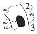
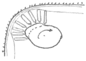
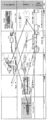
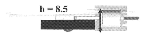
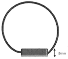
도 1을 참조하면, 미국 특허 3,783,598호는 무브먼트(movement)(2), 드라이브 샤프트(3), 캠(4)들, 피스톤(5)들, 유체로 채워진 모세혈관(6)들, 및 시간을 표시하기 위해 사용된 릴리프 챔버(relief chamber)(7)를 가지는 기구(1)를 기술한다. 자동화된 유체 투여 장치가 존재한다. 전형적인 인슐린 펌프는 호출기(pager)를 닮은 컴퓨터화된(computerized) 장치이고, 환자의 허리띠 또는 벨트에 보통 착용된다. 그러한 펌프는 하루 종일 작고 일정한 양의 인슐린을 전달하도록 프로그램되어 있다. 음식 또는 고혈당 수치를 충당하기 위해 추가 용량이 제공된다. 펌프는 주입 세트라고 하는 튜브 시스템에 부착된 인슐린 저장기를 보유한다. 대부분의 주입 세트는 가이드 바늘로 시작한 다음 플라스틱 캐뉼러(작고 유연한 플라스틱 튜브)를 그대로 두고 드레싱으로 테이프로 묶고 바늘을 제거한다. 캐뉼러는 일반적으로 2~3 일마다 또는 혈당 수준이 목표 범위를 초과할 때 변경된다. 하지만 이러한 장치는 부피가 크며 항상 접근하거나 읽을 수 있는 신체 부위에 있지는 않다.Referring to Figure 1, U.S. Pat.No. 3,783,598 describes movement (2), drive shaft (3), cams (4), pistons (5), fluid filled capillaries (6), and time An
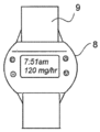
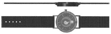
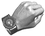
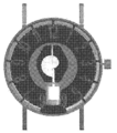
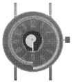
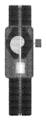
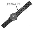
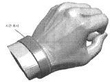
도 2를 참조하면, "글루코워치(CLUCOWATCH)"와 같은 손목 착용 장치가 알려져 있다. 2001년에 개발된 것으로 얘기되는 이러한 종래 기술의 장치는 팔찌(9)에지지되는 케이싱(8)을 갖는다. 저장기는 금연 및 호르몬 요법에 사용되는 경피 의약품 패치(transermal medication patch)와 유사한 패치 상에 인슐린을 분배한다. 그러므로 그것은 낮은 레벨의 전류를 사용하여 피부와 둘러싸는 조직들로부터 수용성의 이온성 약물의 수송을 향상시키고 제어하는 비침습성의, 바늘이 없는 방법을 제공한다.Referring to Fig. 2, a wrist wearing device such as "CLUCOWATCH" is known. This prior art device, which is said to have been developed in 2001, has a
프랑스 특허 1552838호는 전기장에 수은 덩어리(blob)를 넣는 것, 즉 덩어리를 약간 변형할 수 있지만 그러한 덩어리를 한 장소로부터 다른 장소로 옮기지 않을, 전압 차이에 그것을 노출시키는 것을 교시하는데, 이는 출원인이 전기습윤을 수행하기 위해 필수적이라고 여기는 것이다. 또, 그것은 수은을 통한 전류를 생성한다는 단점을 가지는데, 이는 예를 들면 그것을 가열하는 것에 의한 것과 같이 수은에 변화를 가져온다. 또, 수은은 위험한 액체라고 여겨진다.French patent 1552838 teaches putting a mercury blob in an electric field, that is, exposing it to a voltage difference, which may slightly deform the lump, but will not move such a lump from one place to another, where the applicant It is considered necessary to perform wetting. In addition, it has the disadvantage of generating an electric current through mercury, which causes a change in mercury, for example by heating it. In addition, mercury is considered a dangerous liquid.
이들 종래의 장치들은 번거롭고, 값을 나타내거나, 정확성이 부족하거나, 제안된 대로 기능하지 않거나, 많은 사용자에게 너무 비싸기 때문에 상당한 또는 전용 공간을 필요로 한다.These conventional devices are cumbersome, require considerable or dedicated space because they are expensive, lack accuracy, do not function as suggested, or are too expensive for many users.
필요로 하는 것은 측정된 투여량 값의 빠른 판독 표시를 제공하고 제조 비용이 저렴한 시각적 표시기이다.What is needed is a visual indicator that provides a quick readout of the measured dose value and is inexpensive to manufacture.
시각적 표시기 디스플레이 장치는 팔찌, 투명한 모세관 챔버 및 변위 부재(displacement member)를 포함한다. 투명한 모세관 챔버는 표시(indicia)와 일치하며 1차 길이(primary length) 및 1차 길이보다 작은 폭을 갖는다. 변위 부재는 모세관 챔버의 한쪽 끝에 기능적으로 배치되고 그 안에 포함된 유체를 정해진 양만큼 이동시키기 위한 측정 가능한 입력에 응답한다.The visual indicator display device includes a bracelet, a transparent capillary chamber and a displacement member. The transparent capillary chamber conforms to the indicia and has a primary length and a width less than the primary length. The displacement member is functionally disposed at one end of the capillary chamber and responds to a measurable input for moving the fluid contained therein by a predetermined amount.
본 발명의 목적은 최소 공간을 차지하는 시각적 표시기를 제공하는 것이다.It is an object of the present invention to provide a visual indicator that takes up minimal space.
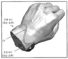
본 발명의 또 다른 목적은 손목, 발목, 머리 또는 인간 신체의 일부 둘레 또는 그러한 일부를 따라서 또는 옷과 스포츠 용품과 같은 물건들 상에 그러한 표시기가 착용될 때와 같이, 직선적이고 튼튼한(straight, rigid) 지시자를 쉽게 허용하지 않는 요구 사항에 적응하는 구부리기 쉬운 시각적 표시기를 제공하는 것이다.Another object of the present invention is straight, rigid, such as when such indicators are worn around wrists, ankles, heads or parts of a human body or along such parts or on objects such as clothes and sporting goods. ) To provide a bendable visual indicator that adapts to requirements that do not easily allow indicators.
본 발명의 다른 목적은 심미적이고, 편안하며, 신뢰 가능하고, 지적으로 매력적인 표시기를 제공하는 것이다.Another object of the present invention is to provide an aesthetic, comfortable, reliable and intelligently attractive indicator.
본 발명의 다른 목적은 약물, 의약품, 연고, 오일들 또는 향수들과 같은 유체의 분배기를 제공하는 것이다.Another object of the present invention is to provide a dispenser of a fluid such as a drug, pharmaceutical, ointment, oils or perfumes.
도 1은 종래 기술의 아날로그 표시기의 측단면도.
도 2는 종래 기술의 제2 표시기의 평면도.
도 3은 본 발명의 제1 실시예의 측단면도.
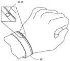
도 4a는 본 발명의 제2 실시예의 사시도.
도 4b는 본 발명의 제2 실시예의 제2 사시도.
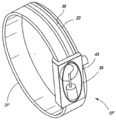
도 5a는 약물 디스펜서로서 사용된, 본 발명의 제2 실시예를 도시하는 도면.
도 5b는 도 5a의 실시예에서 사용하기 위한 카트리지의 측면도.
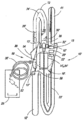
도 5c는 구부러진 상태로 도시된, 도 5a의 실시예에서 사용하기 위한 카트리지의 사시도.
도 6은 하나의 저장기를 가지는, 본 발명의 유체 변위 장치의 부분적으로 분해된 도면.
도 7은 본 발명을 초기화하는데 도움이 되는 특징들을 보여주는, 본 발명의 저장기 및 변위 부재의 단면도.
도 8a 내지 도 8e는 도 8f의 기계적 실시예의 상이한 작동 스테이지들의 진행성 도면(progressive view)들.
도 8f는 본 발명의 완전히 기계적인 구현예의 단면 측면도.
도 9는 직물 적용예(textile application)들을 위한 본 발명의 일 실시예의 개략도.
도 10a 및 도 10b는 전기습윤 효과를 겪는 액적의 사진들을 나란히 도시하는 것으로, 도 10a는 전극에 전압이 인가된 액적을 도시하는 것이고, 도 10b는 전극에 전압이 인가되지 않은 액적을 도시하는 도면.
도 11은 전기습윤 디스플레이의 개략 단면도.
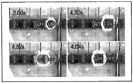
도 12a 내지 도 12d는 전극 피치가 1㎜이고, 높이가 400㎛인 실리콘 오일에서의 물의 액적의 변위를 보여주는 시간 순서(time sequence) 사진들을 도시하는 도면.
도 13은 전기습윤 디스플레이의 개략 단면도.
도 14는 표면 거동 변화를 포함하는 인접한 전극이 활성화되는 것을 도시하는 단면도.
도 15는 모든 전극들이 형성되는 하부 플레이트의 구조를 갖는 전기습윤 디스플레이의 개략 단면도.
도 16은 채널 모양과 제어 전극들의 구조를 보여주는 도 15의 평면도.
도 17은 하부 플레이트 상에 모든 전극들이 구성된 전기습윤 디스플레이의 개략 단면도.
도 18은 전극들 구조를 보여주는 도 17의 평면도.
도 19a 내지 도 19f는 제어 전극들 활성화에 따른 액적의 변위를 보여주는 진행성 개략 도면들.
도 19g 내지 도 19n은 제어 전극들 활성화에 따른 액적의 변위를 보여주는 진행성 개략 도면들.
도 20a 및 도 20b는 제어 전극 활성화에 따른 액적 변형을 보여주는 진행성 개략 도면들.
도 20c 내지 도 20q는 도 20a와 도 20b에 상세하게 나타낸 액적 변형의 순차적인 도면들.
도 21은 투명한 디스플레이 아래의 상호교환 가능한 표시의 조립의 진행성 도면들.
도 22는 전체 튜브에 걸친 아날로그 센서의 대안적인 일 실시예의 단면도.
도 23은 전기습윤 디스플레이에서 구현된, 본 발명의 디지털 센서의 대안적인 일 구현예의 단면도.
도 24a 내지 도 24c는 하나의 제어 전극으로 구성된 전기습윤 디스플레이에서의 액적 변형의 애니메이션(animation)을 보여주는 진행성 개략 도면들.
도 25a 내지 도 25g는 전기습윤 디스플레이에서의 여러 액적들을 모으는 방법을 보여주는 진행성 개략 도면들.
도 26a 내지 도 26f는 다른 유체의 섹션은 닫힌, 유체 액적을 구체화하기 위한 방법을 보여주는 진행성 개략 도면들.
도 27a 내지 도 27e는 2개의 유체 액적들로 유체 액적을 분리하는 방법을 보여주는 진행성 개략 도면들.
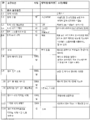
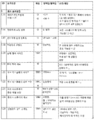
도 28a 내지 도 28d는 본 발명의 요소들의 고려되는 요구 조건을 보여주는 표들.
도 29a는 도 3에서와 같은, 본 발명의 제1 실시예의 개략적인 측단면도.
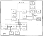
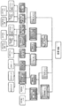
도 29b는 도 29a에 도시된 실시예에 관련된 블록도.
도 29c는 본 발명의 예비 설계의 블록도.
도 30a는 본 발명의 또 다른 블록도.
도 30b는 제1 국면(phase)의 모든 액추에이터들의 또 다른 블록도.
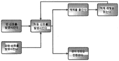
도 30c는 국면 1의 기능도.
도 31a는 국면 인터페이스들에 대한 선택적인 솔루션(optional solution)들을 도시하는 도면.
도 31b는 국면들 인터페이스, 액체의 변위 및 액체 위치 함수들의 탐지를 고려하는 표.
도 31c는 상이한 액체들에 관한 증기압 대 온도를 보여주는 그림.
도 31d는 본 발명의 액체의 변위에 관한 대안적인 수단의 블록도.
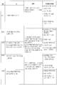
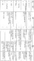
도 32a 내지 도 32d는 액체의 변위에 관한 솔루션들을 고려하는 표.
도 33은 액체 변위 시스템들에 관한 평가 기준을 논의하는 표.
도 34는 액체의 변위에 관한 솔루션들의 순위(ranking)를 논의하는 표.
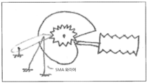
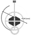
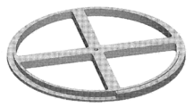
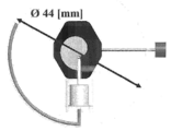
도 35는 본 발명의 나선 휠을 작동시키는 SMA(Shape-Memory Alloy) 깔쭉톱니바퀴를 도시하는 도면.
도 36a 및 도 36b는 본 발명의 전기습윤에 의해 움직인 유체의 개략도들.
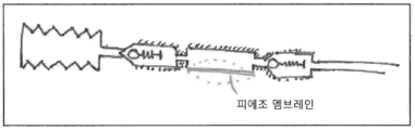
도 37은 본 발명의 피에조 멤브레인(piezo membrane) 펌프의 개략도.
도 38은 본 발명의 원형 연동 펌프의 개략도.
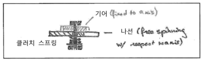
도 39a 및 도 39b는 디스플레이의 수동 설정을 허용하기 위한 클러치의 가능한 구현예를 갖는, 나선 휠 설계의 도식 표현들.
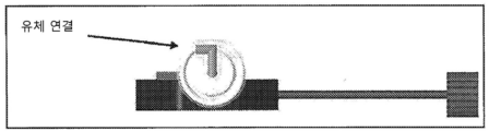
도 40은 Debiotech에 의해 설계된, 본 발명의 장치인 나노펌프(Nanopump)의 사시도.
도 41은 본 발명의 전자기 멤브레인 펌프의 개략도.
도 42a 및 도 42b는 전기습윤 효과의 사진들로서, 도 42a는 전압이 인가되지 않은 것을 보여주는 도면이고, 도 42b는 전압이 인가된 것을 보여주는 도면.
도 43은 전기습윤 디스플레이의 단면의 개략도.
도 44는 전극 피치가 1[㎜]이고, 높이가 400[㎛]인 전극을 갖는 실리콘 오일에서의 물의 액적(droplet)의 연속되는 변위를 도시하는 도면.
도 45는 하나의 액적에서만 변위를 유도하는, 액체 기둥을 갖는 본 발명의 표시기를 가지는 실시예를 도시하는 도면.
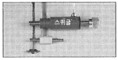
도 46은 본 발명의 스퀴글 드라이브(Squiggle drive)의 평면도.
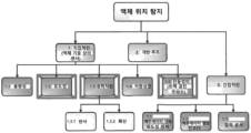
도 47은 표시기 액체 위치의 탐지를 위한 솔루션 제안들을 도시하는 도면.
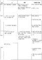
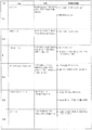
도 48은 액체 위치의 탐지를 위한 솔루션들을 논의하는 표.
도 49는 액체 감지 방법들에 관한 평가 기준을 논의하는 표.
도 50은 액체 레벨 센서들의 선택된 솔루션들의 순위를 논의하는 표.
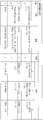
도 51a 및 도 51b는 전기습윤 디스플레이 상의 아날로그 센서 또는 디지털 센서로서의 용량성 센서의 2가지 상이한 구현예들을 도시하는 도면들.
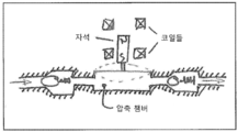
도 52는 본 발명의 유도성 센서의 개략도.
도 53a는 본 발명의 인코더 시스템의 개략도.
도 53b는 절대적 위치선정을 위한 본 발명의 인코더 휠의 또 다른 개략도.
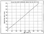
도 54는 튜브에서의 액체 길이에 미치는 온도의 효과의 그래프.
도 55는 튜브에서의 액체 길이에 미치는 온도의 효과의 또 다른 그래프.
도 56은 물에 용해된 헬륨을 고려하는, 상이한 입력 파라미터들에 관한 계산 기포 반경들/튜브 반경 비의 그래프.
도 57은 감압 챔버 대 튜브 직경 및 챔버 부피에서의 최종 압력의 그래프.
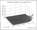
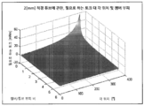
도 58은 감압 챔버 대 챔버 부피 및 튜브 직경에서의 최종 압력의 윤곽선 도면(contour plot).
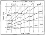
도 59는 피스톤 상의 최대 힘 대 튜브 직경, 챔버 부피 및 피스톤 직경의 등위 표면(isosurface)들의 3D 그래프.
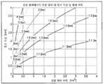
도 60은 피스톤 스트로크(piston stroke) 대 튜브 직경 및 피스톤 직경의 도면.
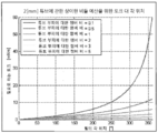
도 61은 11[㎽] 평균 전력 소모(최대 용납 가능한 전력) 미만, 그리고 3[㎽] 미만인 함수(function)를 허용하는 구성예들을 예시하는 그래프(30% 전체 효율을 고려하는).
도 62는 액체-진공 인터페이스의 개략도.
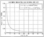
도 63은 실리콘-실리콘 인터페이스에 관한 리턴 시간(return time) 등위 표면들의 그래프.
도 64는 물-물 인터페이스에 관한 리턴 시간 등위 표면들의 그래프.
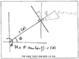
도 65는 나선 모양의 경사로(ramp)에 작용하는 힘들을 도시하는 개략도.
도 66은 튼튼한 압축 챔버를 갖는 일반화된 나선 시스템.
도 67은 아르키메데스 나선(archimedean spiral)을 도시하는 도면.
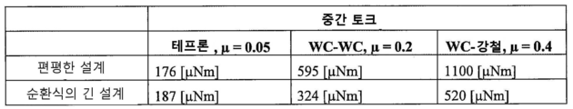
도 68은 2[㎜] 튜브에 관한 튜브 부피 비에 대한 요구되는 토크 대 각 위치 및 챔버를 나타내는 곡선을 도시하는 도면.
도 69는 2[㎜] 튜브 직경에 관한, 상이한 챔버/튜브 부피 비들에 관한 토크 대 각 위치의 상이한 비율들의 그래프.
도 70은 물과 실리콘 오일에 관한, 나선 휠 대 원하는 리턴 시간에 대한 요구된 토크의 그래프.
도 71은 전기습윤 권리의 개략 단면도와 등가 전기 개략도.
도 72는 전압의 함수로서, 상이한 매체에서의 물의 변위 주파수의 그래프.
도 73은 글로벌 조합(global combination)들뿐만 아니라, 선택적인 솔루션들의 요약(summary)을 나타내는 형태학상 상자(morphologic box)들을 도시하는 도면.
도 74는 본 발명의 실시예의 변위 장치들의 5개의 상이한 옵션(option)들의 표.
도 75는 실시예 1의 파라미터들 - 나선 캠(spiral cam) - 을 논의하는 표.
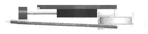
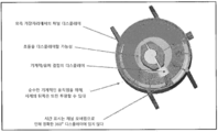
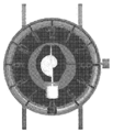
도 76은 본 발명의 시계 무브먼트의 사진들.
도 77은 본 발명에서 사용 가능한 규격품 무브먼트(off-the-shelf movement)들의 사진들.
도 78a는 디지털 수정 발진식 시계의 개략도.
도 78b는 기계식 시계의 개략도.
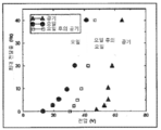
도 79는 리턴 스프링 힘과 저장기 두께 대 저장기 직경의 그래프.
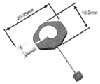
도 80a는 편평하고 표시기 튜브 및 시계 무브먼트가 있는 실시예(1)의 평면도.
도 80b는 편평한, 실시예 1의 측면도.
도 80c는 편평한, 실시예 1의 정면도.
도 81은 편평한, 실시예 1의 저장기를 통한 단면이 취해진 단면도.
도 82는 편평한, 실시예 1의 캠 휠의 사시도.
도 83a는 긴 저장기를 갖는 실시예 1의 평면도.
도 83b는 긴 저장기를 갖는 실시예 1을 통한 단면의 측면도.
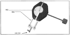
도 84는 시계에서 패키징된, 실시예 1의 평면도.
도 85는 도 84의 시계의 메커니즘을 통한 단면도.
도 86a는 디스플레이 마스크가 없는, 선형 디스플레이를 갖는 실시예 1의 평면도.
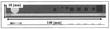
도 86b는 디스플레이 마스크가 있는, 선형 디스플레이를 갖는 실시예 1의 평면도.
도 86c는 본 발명의 선형 디스플레이가 있는 실시예 1의 측면도.
도 87은 본 발명의 구부러지기 쉬운 플라스틱 팔찌를 도시하는 도면.
도 88은 구부러지기 쉬운 팔찌에서의 나선 무브먼트의 구현예를 사시도와 측면도로 나란히 나타낸 도면.
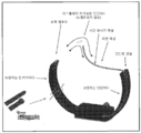
도 89는 손목 아래의 메커니즘이 있는, S자 형상의 디스플레이의 선택적인 구현예를 도시하는 도면.
도 90은 본 발명의 피스톤에 작용하는 힘들의 개략도.
도 91은 2[㎜]의 내부 직경 휠, 4.5[㎜]의 스트로크에 관한 토크 대 각 위치의 그래프.
도 92는 토크들을 논의하는 표.
도 93은 본 발명의 3개의 플립-플롭(flip-flop) 기반의 드라이버의 개략도.
도 94는 본 발명의 전극들의 연결의 개략도.
도 95는 본 발명의 간략화된 감지 회로의 개략도.
도 96은 본 발명의 구동 전자 장치들의 더 완전한 개략도.
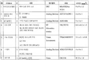
도 97은 도 96의 시스템을 구동하기 위해 요구되는 구성요소들을 열거하는 표.
도 98은 본 발명의 전기습윤 디스플레이 시계의 일 실시예의 평면도 및 측면도.
도 99a 내지 도 99e는 저비용의 전기 또는 고급(high-end) 기계적 무브먼트의 통합의 개략도들.
도 100a 내지 도 100d는 본 발명의 조립 단계들의 도면들.
도 101a 내지 도 101f는 실시예 1의 도면들과 본 발명의 시계에서의 원형 유체 채널의 통합을 도시하는 도면.
도 102a 내지 도 102c는 실시예 1의 가변적인 디스플레이 변형예들과 채널 모양들을 도시하는 도면들.
도 103a 내지 도 103h는 실시예 2의 사시도들과 본 발명의 탄성이 있는 팔찌에서의 통합(integration)을 도시하는 도면.
도 104는 실시예 2의 일 변형예의 사시도.
도 105는 실시예 2의 또 다른 변형예의 평면도.
도 106a 내지 도 106f는 실시예 3의 사시도들과 본 발명의 "S" 디스플레이에서의 통합을 도시하는 도면.
도 107은 실시예 3의 일 변형예의 사시도.
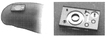
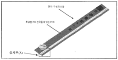
도 108은 본 발명의 투명한 ITO 전극들과 전가 구성요소들을 갖는 PCB의 사시도.
도 109a는 본 발명의 감지 전극들의 도 108의 상세한 사시도 A.
도 109b는 본 발명의 구동 전극들의 도 108의 상세한 사시도 A.
도 110은 전기습윤의 개략도.
도 111은 전기습윤에 기초한 본 발명의 팔찌에서의 시간의 표시의 사시도.
도 112는 도 111의 시간 표시를 상세하게 나타낸 사시도.
도 113은 본 발명의 팔찌에 관한 폐쇄하는 장치들의 사시도.
당업자라면 도면들에서의 요소들이 간략화 및 명확화를 위해 예시되고 반드시 실제 크기대로 그려지지는 않았음을 알게 될 것이다. 예를 들면, 본 발명과 본 발명의 실시예들의 이해를 향상시키는 것에 도움이 되기 위해 다른 요소들에 대해 치수들이 과장될 수 있다. 또, "제1", "제2" 등이 본 명세서에서 사용될 때, 그것들의 사용은 유사한 요소들 사이에서 구별하기 위해 의도되고 반드시 순차적이거나 연대기적인 순서를 묘사하기 위한 것은 아니다. 또한, 상세한 설명부 및/또는 청구항들에서의 "앞(front)", "뒤(back)", "위(top)", "아래(bottom)" 등과 같은 상대적 용어들은 반드시 배타적인 상대적 위치를 묘사하기 위해서 사용되는 것은 아니다. 그러므로 당업자라면 그러한 용어들이 다른 용어들과 서로 교환 가능할 수 있고 본 명세서에서 묘사된 실시예들은 명백히 예시되거나 달리 기술된 것들 외의 다른 오리엔테이션(orientation)들에서 작동할 수 있다는 것을 이해할 것이다.1 is a side sectional view of a conventional analog display.
2 is a plan view of a second indicator of the prior art.
3 is a side cross-sectional view of the first embodiment of the present invention.
4A is a perspective view of a second embodiment of the present invention.
4B is a second perspective view of a second embodiment of the present invention.
5A shows a second embodiment of the invention, used as a drug dispenser.
5B is a side view of the cartridge for use in the embodiment of FIG. 5A.
5C is a perspective view of the cartridge for use in the embodiment of FIG. 5A, shown in a bent state.
6 is a partially exploded view of the fluid displacement device of the present invention, with one reservoir.
7 is a cross-sectional view of the reservoir and displacement member of the present invention, showing features that help to initialize the present invention.
8A-8E are progressive views of different operating stages of the mechanical embodiment of FIG. 8F.
8F is a cross-sectional side view of a fully mechanical embodiment of the invention.
9 is a schematic diagram of one embodiment of the present invention for textile applications.
10A and 10B show photographs of droplets undergoing the electrowetting effect side by side, FIG. 10A shows a droplet in which a voltage is applied to the electrode, and FIG. 10B shows a droplet in which no voltage is applied to the electrode. .
11 is a schematic cross-sectional view of an electrowetting display.
12A to 12D are time sequence photographs showing displacement of water droplets in silicone oil having an electrode pitch of 1 mm and a height of 400 µm.
13 is a schematic cross-sectional view of an electrowetting display.
14 is a cross-sectional view showing that adjacent electrodes including surface behavior changes are activated.
15 is a schematic cross-sectional view of an electrowetting display having a structure of a bottom plate on which all electrodes are formed.
16 is a plan view of FIG. 15 showing the channel shape and the structure of the control electrodes.
17 is a schematic cross-sectional view of an electrowetting display in which all electrodes are configured on a lower plate.
18 is a plan view of FIG. 17 showing the structures of the electrodes.
19A-19F are progressive schematic diagrams showing displacement of droplets with activation of control electrodes.
19G-19N are progressive schematic diagrams showing displacement of droplets according to activation of control electrodes.
20A and 20B are progressive schematic diagrams showing droplet deformation according to control electrode activation.
20C to 20Q are sequential views of droplet modification shown in detail in FIGS. 20A and 20B.
21 is a progressive view of the assembly of an interchangeable display under a transparent display.
22 is a cross-sectional view of one alternative embodiment of an analog sensor across an entire tube.
23 is a cross-sectional view of an alternative implementation of the digital sensor of the present invention, implemented in an electrowetting display.
24A-24C are progressive schematic diagrams showing the animation of droplet deformation in an electrowetting display consisting of one control electrode.
25A-25G are progressive schematic diagrams showing a method of collecting various droplets in an electrowetting display.
26A-26F are progressive schematic diagrams showing a method for embodying a fluid droplet, wherein another section of fluid is closed.
27A-27E are progressive schematic diagrams showing a method of separating a fluid droplet into two fluid droplets.
28A-28D are tables showing the considered requirements of the elements of the present invention.
29A is a schematic side cross-sectional view of the first embodiment of the present invention, as in FIG. 3;
29B is a block diagram related to the embodiment shown in FIG. 29A.
29C is a block diagram of a preliminary design of the present invention.
30A is another block diagram of the present invention.
30B is another block diagram of all actuators of the first phase.
30C is a functional diagram of
31A shows optional solutions for phase interfaces.
31B is a table considering detection of phases interface, liquid displacement and liquid position functions.
31C is a plot showing vapor pressure versus temperature for different liquids.
31D is a block diagram of an alternative means of displacement of the liquid of the present invention.
32A-32D are tables that consider solutions regarding displacement of liquids.
33 is a table discussing evaluation criteria for liquid displacement systems.
34 is a table discussing the ranking of solutions regarding displacement of liquids.
35 is a view showing a SMA (Shape-Memory Alloy) sprocket operating the spiral wheel of the present invention.
36A and 36B are schematic views of a fluid moved by electrowetting of the present invention.
37 is a schematic diagram of a piezo membrane pump of the present invention.
38 is a schematic diagram of a circular peristaltic pump of the present invention.
39A and 39B are schematic representations of a spiral wheel design, with a possible implementation of a clutch to allow manual setting of the display.
40 is a perspective view of a nanopump (Nanopump), the device of the present invention, designed by Debiotech.
41 is a schematic diagram of an electromagnetic membrane pump of the present invention.
42A and 42B are pictures of the electrowetting effect, and FIG. 42A is a diagram showing that a voltage is not applied, and FIG. 42B is a diagram showing that a voltage is applied.
43 is a schematic view of a cross-section of an electrowetting display.
FIG. 44 is a diagram showing the continuous displacement of droplets of water in silicone oil having electrodes with an electrode pitch of 1 [mm] and a height of 400 [µm].
45 shows an embodiment with an indicator of the present invention having a liquid column, which induces displacement only in one droplet.
Fig. 46 is a plan view of a Squiggle drive of the present invention.
FIG. 47 shows solution proposals for detection of indicator liquid location.
48 is a table discussing solutions for detection of liquid location.
49 is a table discussing evaluation criteria for liquid detection methods.
50 is a table discussing the ranking of selected solutions of liquid level sensors.
51A and 51B are diagrams showing two different implementations of a capacitive sensor as an analog sensor or a digital sensor on an electrowetting display.
52 is a schematic diagram of an inductive sensor of the present invention.
53A is a schematic diagram of an encoder system of the present invention.
53B is another schematic diagram of the encoder wheel of the present invention for absolute positioning.
54 is a graph of the effect of temperature on liquid length in a tube.
55 is another graph of the effect of temperature on the length of liquid in a tube.
56 is a graph of calculated bubble radii/tube radii ratios for different input parameters, taking into account helium dissolved in water.
57 is a graph of the final pressure in the decompression chamber versus tube diameter and chamber volume.
58 is a contour plot of the final pressure in the decompression chamber to chamber volume and tube diameter.
59 is a 3D graph of isosurfaces of maximum force on the piston versus tube diameter, chamber volume and piston diameter.
FIG. 60 is a plot of piston stroke versus tube diameter and piston diameter.
FIG. 61 is a graph (considering 30% overall efficiency) illustrating examples that allow functions below 11 [㎽] average power consumption (maximum acceptable power), and below 3 [㎽].
62 is a schematic diagram of a liquid-vacuum interface.
63 is a graph of return time isosurfaces for a silicon-silicon interface.
64 is a graph of return time isosurfaces for a water-water interface.
Fig. 65 is a schematic diagram showing forces acting on a spiral ramp.
66 is a generalized spiral system with a robust compression chamber.
67 shows the Archimedean spiral.
FIG. 68 is a curve showing the required torque versus angular position and chamber for tube volume ratio for a 2 [mm] tube.
FIG. 69 is a graph of different ratios of torque to angular position for different chamber/tube volume ratios, relative to 2 [mm] tube diameter.
FIG. 70 is a graph of the required torque versus spiral wheel versus desired return time for water and silicone oil.
Fig. 71 is a schematic cross-sectional view and an equivalent electricity schematic diagram of an electrowetting right.
72 is a graph of the displacement frequency of water in different media as a function of voltage.
FIG. 73 is a diagram showing morphologic boxes showing summaries of selective solutions as well as global combinations.
74 is a table of five different options of displacement devices of an embodiment of the present invention.
FIG. 75 is a table discussing the parameters of Example 1-spiral cam.
76 is a photograph of the watch movement of the present invention.
77 is a photograph of off-the-shelf movements usable in the present invention.
78A is a schematic diagram of a digital crystal oscillating clock.
78B is a schematic diagram of a mechanical watch.
79 is a graph of return spring force and reservoir thickness versus reservoir diameter.
80A is a plan view of embodiment (1) that is flat and has an indicator tube and a watch movement.
80B is a side view of Example 1, which is flat.
80C is a front view of Example 1, which is flat.
81 is a cross-sectional view taken through the reservoir of Example 1, flat.
82 is a perspective view of the cam wheel of Example 1, which is flat.
83A is a plan view of Example 1 with a long reservoir.
83B is a side view in cross section through Example 1 with a long reservoir.
84 is a plan view of Example 1, packaged in a watch.
85 is a cross-sectional view through the mechanism of the watch of FIG. 84;
86A is a top view of Example 1 with a linear display, without a display mask.
86B is a top view of Example 1 with a linear display, with a display mask.
86C is a side view of
87 is a view showing the bendable plastic bracelet of the present invention.
88 is a view showing a side view and a side view of an embodiment of a spiral movement in a bendable bracelet.
89 shows an alternative implementation of an S-shaped display with a mechanism under the wrist.
90 is a schematic diagram of forces acting on the piston of the present invention.
FIG. 91 is a graph of torque versus angular position for an inner diameter wheel of 2 [mm], a stroke of 4.5 [mm].
92 is a table discussing torques.
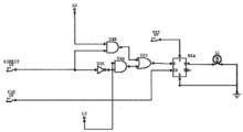
93 is a schematic diagram of three flip-flop based drivers of the present invention.
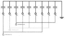
94 is a schematic diagram of the connection of the electrodes of the present invention.
95 is a schematic diagram of a simplified sensing circuit of the present invention.
96 is a more complete schematic diagram of the drive electronics of the present invention.
FIG. 97 is a table listing the components required to drive the system of FIG. 96;
98 is a plan and side view of an embodiment of an electrowetting display watch of the present invention.
99A-99E are schematic diagrams of the integration of a low-cost electrical or high-end mechanical movement.
100A-100D are views of the assembly steps of the present invention.
101A-101F illustrate the integration of the circular fluid channels in the views of Example 1 and the present invention.
102A to 102C are diagrams showing variable display variants and channel shapes of
103A-103H show perspective views of Example 2 and integration in the elastic bracelet of the present invention.
104 is a perspective view of a modification of Example 2;
105 is a plan view of still another modification of Example 2.
106A-106F show perspective views of Example 3 and integration in the "S" display of the present invention.
107 is a perspective view of a modification of Example 3;
108 is a perspective view of a PCB with transparent ITO electrodes and imputation components of the present invention.
109A is a detailed perspective view A of FIG. 108 of sensing electrodes of the present invention;
109B is a detailed perspective view A of FIG. 108 of drive electrodes of the present invention;
110 is a schematic diagram of electrowetting.
111 is a perspective view of an indication of time in the bracelet of the present invention based on electrowetting.
112 is a perspective view showing in detail the time display of FIG. 111;
113 is a perspective view of the closing devices of the bracelet of the present invention.
Those skilled in the art will appreciate that elements in the drawings are illustrated for simplicity and clarity and are not necessarily drawn to scale. For example, dimensions may be exaggerated for other elements to help improve understanding of the invention and embodiments of the invention. Also, when “first”, “second”, and the like are used herein, their use is intended to distinguish between similar elements and is not necessarily intended to describe sequential or chronological order. In addition, relative terms such as “front”, “back”, “top”, “bottom”, etc. in the detailed description and/or claims must necessarily indicate an exclusive relative position. It is not used to describe. Therefore, those skilled in the art will understand that such terms may be interchangeable with other terms, and that the embodiments described herein may operate in orientations other than those explicitly illustrated or otherwise described.
다음 기술 내용은 어떤 식으로든 본 발명의 범주를 제한하려고 의도되는 것은 아닌데, 이는 그것들이 사실상 전형적인 것이고 본 발명의 출원일에 본 발명자들에게 알려진 본 발명의 최상의 모드를 묘사하는 역할을 하기 때문이다. 따라서, 본 발명의 취지 및 범주로부터 벗어나지 않으면서 개시된 전형적인 실시예들에서 묘사된 요소들 중 임의의 것의 배치 및/또는 기능에 있어서 변경들이 이루어질 수 있다.The following description is not intended to limit the scope of the invention in any way, since they are in fact typical and serve to depict the best mode of the invention known to the inventors on the filing date of the invention. Thus, changes can be made in the arrangement and/or function of any of the elements depicted in the disclosed exemplary embodiments without departing from the spirit and scope of the invention.
시각적 표시기 디스플레이 장치는 팔찌, 투명한 모세관 챔버, 및 변위 부재를 포함한다. 투명한 모세관 챔버는 표시에 매칭되고 1차 길이(primary length)와 그러한 1차 길이보다 작은 폭을 가진다. 변위 부재는 모세관 챔버의 한쪽 끝에 기능적으로 배치되고 정해진 양을 포함하는 유체를 움직이기 위한 측정 가능한 입력에 반응한다.The visual indicator display device includes a bracelet, a transparent capillary chamber, and a displacement member. The transparent capillary chamber is matched to the indicia and has a primary length and a width less than that primary length. The displacement member is functionally disposed at one end of the capillary chamber and responds to a measurable input for moving a fluid containing a defined amount.
적합한 유체는 오일, 로션(lotion), 또는 약물 또는 다른 의약품과 같은 액체일 수 있다. 변위 부재는 사용자가 표시기 표면을 옮기기 위한 측정 가능한 입력에 응답하는 모세관 챔버의 일 단부에 부착되어 사용자가 표시로부터 측정값을 읽을 수 있게 한다.Suitable fluids can be oils, lotions, or liquids such as drugs or other medicines. The displacement member is attached to one end of the capillary chamber in response to a measurable input for the user to move the indicator surface, allowing the user to read the measurement from the indication.
도 3을 참조하면, 본 발명의 아날로그 표시기(10)가 투약량을 표시한다. 표시기(10)는 저장기(12), 펌프(14), 측정 장치(16), 제어기(20)에서의 피드백 회로 및 전원(power supply)(22')을 포함한다. 저장기(12)는 길이 방향 축(24)을 가지고, 이러한 길이 방향 축(24)을 따라서 표시 또는 스케일(scale) 장치(26)가 배치되며 적어도 하나의 표시기 표면(30)에 의해 경계가 정해진 유체(28)를 담도록 되어 있다. 바람직한 일 실시예에서, 펌프(14)는 마이크로 모터(micro motor)(34)에 의해 구동된 나사(33) 상에 장착된 플런저(plunger)(32)로 이루어진다. 플런저(32)는 일반적으로 유체(28)가 플런저의 상부 표면(31)과 하부 표면(35) 사이에서 각각 지나가는 것에 대항하여 밀봉하기 위해, 그것의 원주 주위에 배치된 오-링 씰(O-ring seal)(29)을 사용한다. 펌프(14)는 저장기(12)로부터 유체(28)를 카테터(catheter)(36)로 퍼 올린다. 바람직한 일 실시예에서, 측정 장치(16)는 시간을 측정하고 시간이 측정된 값을 피드백 회로(20)와 통신하는 전자 시계(electronic clock)이다. 전원(22)에 의해 전력을 공급받는 피드백 회로(20)는 스케일 장치(26) 상의 위치에 대응하는 측정 장치(16)로부터 측정된 시간 입력을 수신하고, 그것에 응답하여 표면(30)이 표시(26) 상의 대응하는 위치에 관하여 원하는 위치(일반적으로 유체 분배의 원하는 속도(rate)와 같게 조정된)에 도달할 때까지 펌프(14)가 저장기(12)로부터 유체(28)를 퍼 올리거나 이동시키도록 작동시킨다. 전원(22)은 펌프(14)와 피드백 회로(20)에 전력을 공급한다. 도시된 것처럼, 저장기(12)는 카테터(36) 내로 유체(28)가 통하게 한다. 걸쇠(clasp)(52)가 팔찌(21)를 생성하기 위해 장치(10)의 단부(end)들을 연결한다.Referring to Fig. 3, the
또, 선택적으로 광 섬유와 LED 광원이 알려진 방식으로 저장기(12)에서 유체(28)를 비춘다.Also, the optical fiber and the LED light source selectively illuminate the fluid 28 in the
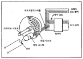
전위차계(potentiometer)(56)는 변위 제어 시스템(60)에 설정하는 전압을 조절한다. 변위 제어 시스템(60)은 예를 들면 플런저(32)에 인접하게 위치한 트래커(tracker) NSE-5310(그 사양은 부가물 A로서 본 명세서에 참조로 통합되고 2009년 8월 21에 출원된 미국 가출원 61/235,725호에 첨부되어 있다)와 같은 증분 위치 센서(incremental position sensor)(62)를 포함한다. 이 제어 시스템(60)은 대략 0.3㎜(통상적으로)인 거리에서 칩에 인접하게 놓인 외부 자기 스트립(54)의 증분 위치를 끌어내기 위해 칩(62) 상의 홀 요소 어레이(hall element array)가 사용되는 직접적인 디지털 출력을 위한 인코딩을 포함하고, 이러한 자기 스트립(64)은 플런저(32)에 부착되어 플런저(32)와 함께 옮겨진다. 이러한 센서 어레이는 0인 기준 점(reference point)을 제공하기 위해 자기 스트립의 단부들을 탐지한다.A
대안적인 일 실시예에서, 전원(22)은 태양 전지들, 감긴 시계 스프링, 진동하는 덩어리(oscillating mass)(자동 시계들에서 사용된 것과 같은)에 의해 캡처된(captured) 무브먼트이거나 압축된 공기를 저장하는 공압 시스템일 수 있다.In one alternative embodiment, the
예를 들면 오전 6시와 같은 처음 위치로 유체(28)를 되돌리기 위해, 플런저(32)는 리턴 스프링(40) 또는 자기 장치(미도시)에 의해 되돌려질 수 있다. 리턴 라인(return line)(42)을 포함하는 다른 옵션(option)들이 물론 생각될 수 있고, 이러한 리턴 라인(42)은 표시기(10)를 재설정하기 위해 모터(34)를 간단히 거꾸로 하는 것을 허용한다.To return the fluid 28 to its initial position, for example 6 am, the
적합한 모터(34)는 미국 뉴욕 소재의 New Scale Technologies사로부터 입수 가능한 상표명이 SQUIGGLETM인 것이 참고된다.It is noted that a
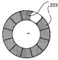
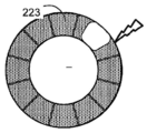
이제 도 4a 및 도 4b를 참조하면, 본 발명의 아날로그 표시기의 적용예는 손목 시계 또는 사용자의 손목 둘레에 착용된 목걸이(10)이다. 저장기(12')는 투명하거나 반투명한 재료로 만들어질 수 있거나 임의의 원하는 모양으로 형성된, 투명하고 반투명한 재료의 혼합물로 만들어질 수 있다. 그것은 플라스틱, 고무, 실리콘 또는 임의의 적합한 재료로 만들어질 수 있다. 탄력성 재료는 팔찌(21')가 사용자의 손목 위에서 늘어날 수 있다는 장점을 가진다. 게다가, 유체 디스플레이(23)는 케이싱(43) 상의 표준 시계 표면(39)으로 보충될 수 있다.Referring now to FIGS. 4A and 4B, an application example of the analog indicator of the present invention is a wrist watch or a
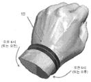
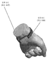
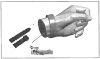
이제 도 5a를 참조하면, 본 발명은 인슐린과 같은 액체 약물(28)들의 투약량을 복용시키기 위해 사용된 장치(10")로서 구성될 수 있다. 그러한 실시예에서, 휘어질 수 있는 튜브는 투약량 제어 장치(18)를 포함하는 하우징(13)에 부착된 배치 가능한 의약품 저장기 카트리지(12')이다. 장치(10")는 손목 시계와 같이 운반되고, 이 경우 휘어질 수 있는 카트리지(12')가 그것의 밴드(band)의 일부로서의 역할을 한다. 표시기(10")는 저장기(12'), 선형 드라이브(linear drive)(14'), 선택적인(optional) 피드백 회로(16'), 제어기(20'), 및 전원(22')을 포함한다. 저장기(12')는 길이 방향 축(24')을 가지고 이러한 길이 방향 축(24')을 따라 표시(26')가 배치되며 적어도 하나의 표시기 표면(30')에 의해 경계가 정해진 유체(28)를 포함하게 되어 있다. 바람직한 일 실시예에서 선형 드라이브(14')는 마이크로 모터(34')에 의해 구동되는 긴 휘어질 수 있는 나삿니가 있는(threaded) 샤프트(33') 상에 장착된 구형 플런저(32')를 구동한다. 샤프트(33')는 바람직하게는 NITINOL과 같은 초탄성 재료로 만들어진다. 선형 드라이브(14')는 피스톤(35)(바람직하게는 고무와 같은 휘어질 수 있는 재료로 만들어진)에 맞닿아 플런저(32')를 구동하고, 이러한 피스톤(35)은 유체(28)를 저장기(12')를 따라 누르며 결국에는 캐뉼러 튜브 또는 카테터(36')를 통과시킨 다음 유체(28)를 환자의 신체 내로 안내한다. 장치(10")의 전자 장치는 의사에 의해 처방된 만큼 규칙적인 간격으로 또는 일정하게 유체의 프로그램된 투약량이 복용되는 것을 보장한다. 선택적으로 캐뉼러를 통한 착용자의 신체 내로 지나가는 대신에, 피부를 통해 환자의 신체 내로 약물의 느린 전파를 위해, 환자가 착용한 흡수성 패치(25)를 유체(28)가 채우는 것을 주목하라. 의약품이 패치(25)를 거쳐 투여되는 경우, 의약품이 그것의 의도된 효과를 가지기 전에 의약품이 증발하는 것을 방지하기 위해(즉, 피부를 통한 확산), 패치는 반투과성인 외부 층을 포함할 수 있다. 또, 향수가 유사한 방식으로 전달될 수 있다. 특히 향수를 분배하는 실시예에 관해서는, 패치가 하우징(13) 밑에 또는 하우징의 측면에 부분적으로 또는 전체적으로 위치할 수 있고 동일한 것을 생물에 부착할 필요를 회피하기 위해 생물에 직접적으로보다는 일시적인 접착제를 사용하여 고정될 수 있다. 그러한 패치는 교체 패치들이 더러워진 패치들을 즉시 대체할 수 있도록, "POST-IT" 노트와 같이 생물에 인접하게 하우징(13)의 뒤 또는 임의의 측에 맞닿아 정해진 영역(39로 표시된(marked) 원형 영역과 같은)에서 교체되도록 크기가 정해질 수 있다.Referring now to Fig. 5A, the present invention may be configured as a
바람직한 실시예에서, 적절한 투여량을 보장하도록 선형 드라이브(14')의 회전(turn)들의 개수가 기록되고 제어된다. 전자 장치들은 전원(22')에 의해 전력이 공급된다. 대안적으로, 피스톤(35)의 위치는 도 3에 도시된 위 실시예에서 설명된 것과 같은 방식으로 제어될 수 있다. 카트리지(12')는 하우징(13)의 일 측(13')에서 그것의 피스톤(35)이 플런저(32')에 인접한 채로 설치되고 다른 측(13")에서는 슬라이드 가능한 탭(tab)(54)에 연결된 피어싱 튜브(piercing tube)(52)를 포함하는 피어싱 메커니즘(50)에 인접하게 설치된다. 사용자는 유체(28)가 캐뉼러(38)를 통해 환자의 신체 내로 흘러들어가는 것을 허용하기 위해, 카트리지(12')의 상부 멤브레인(upper membrane)(56)을 피어싱 튜브(52)로 하여금 관통하게 하기 위해 탭(54)을 미끄러지게 할 수 있다. 향수가 분배되는 경우, 이러한 피어싱은 향수가 대기로 또는 전도성 채널(미도시)을 거쳐 사용자의 피부로, 사용자의 피부 가까이로 또는 사용자의 피부에 인접하게 전달되는 것을 허용하기 위해 카트리지(12')의 한쪽 단부를 개방하는 역할을 한다(예를 들면, 직접적으로 그리고 패치를 통해).In a preferred embodiment, the number of turns of the linear drive 14' is recorded and controlled to ensure proper dosage. The electronic devices are powered by a power source 22'. Alternatively, the position of the
카트리지(12')에 부착되거나 카트리지(12')에 통합된 외부 자기 스트립(발생된 자기장이 카트리지의 길이를 따라 증가 또는 감소하는 자성을 가지는)을 사용하는 실시예에서는, 컴퓨터 제어기가 이를 사용하여 환자에게 투여되는 복용량을 조절할 수 있다.In embodiments that use an external magnetic strip (generated magnetic field having a magnetic field that increases or decreases along the length of the cartridge) attached to or integrated into the cartridge 12', the computer controller uses it. The dosage administered to the patient can be adjusted.
이전의 실시예에서와 같이, 전원(22')은 배터리, 태양열 발전, 감긴 시계 스프링, 진동하는 덩어리(자동 시계들에서 사용된 것과 같은), 또는 압축된 공기를 저장하는 공압 시스템일 수 있다.As in the previous embodiment, the power source 22' can be a battery, solar power, a wound watch spring, a vibrating mass (such as used in automatic watches), or a pneumatic system that stores compressed air.
카트리지(12')가 완전히 분배된 후, 플런저(32')를 끌어넣기 위해 하우징(13) 상의 버튼(미도시)이 작동될 수 있다. 피스톤(35)은 환자로부터의 유체의 임의의 흡기(aspiration)를 방지하기 위해 정지된 상태로 있고, 캐뉼러는 여전히 신체에 연결된 채로 있어야 한다. 일단 끌어넣어지면, 장치(10")는 대체 카트리지(12')가 다시 끼워질 수 있다.After the cartridge 12' is fully dispensed, a button (not shown) on the
앞선 실시에에서처럼, 적합한 모터(34)는 이미 기술된 SQUIGGLETM 모터이다.As in the previous implementation, a
약물 투여 장치가 또한 손목 시계로서의 역할을 할 수 있도록 하기 위해 하우징(13)은 시계 면(39)과 대응하는 무브먼트(movement)(미도시)에 맞게끔 되어 있을 수 있다는 점을 주목하라.Note that the
선택적으로, 약물 투여 장치(10")의 나삿니가 있는 로드(rod)(33')는 하우징(13)의 측(side)(13") 상에서 연결하는 튜브(41)에서 둘러싸이고 하우징의 측(13')에 다시 연결하여 2개 또는 다중 밴드식(multi-banded) 손목 시계의 시각적 효과를 주기 위해 착용자의 손목 둘레를 감싼다.Optionally, the threaded rod 33' of the
그러한 약물 투여 장치(10")에서 사용된 카트리지(12')가 인슐린 또는 다른 약물이 지속된 주사에 대해 적합한지를 표시하는 화학적 리트머스(litmus)-타입 표시기를 포함하게 될 것이라는 점이 예견된다. 이러한 징조는 유체가 사용에 적합한지를 표시하는 컬러로부터 그러한 유체가 더 이상 사용하기에 적합하지 않다는 것을 표시하는 또 다른 컬러로 컬러를 변경하는 카트리지(12')의 요소에 의해 표현될 수 있다.It is foreseen that the cartridge 12' used in such
또, 장치(10")는 캐뉼러를 수동으로(디스펜서 헤드 또는 버튼을 통해) 또는 자동으로(본 발명의 투여량 제어를 통해) 작동될 수 있는 흡출 헤드(aspirating head)로 대체함으로써 향수 분배기로서 사용될 수 있다.The
이제 도 6을 참조하면, 교체 실시예에서 시계 무브먼트(132)의 굴대(stem)에 부착된 캠(cam)(152)은 축 방향으로 병진운동하기 위해 밀봉된 베어링(162)들 상에 장착된, 피스톤 샤프트(160)를 통해 유체 변위 장치(90)에 연결되고, 이는 그것의 캠 표면(164)에 의해 그것의 축 방향 병진운동시 안내된다. 피스톤 샤프트(160)는 저장기(36')의 휘어질 수 있는 롤링 다이어프램(170)에 맞닿아 작용하는 피스톤 헤드(166)에 연결된다(대안적으로, 물론 피스톤은 도 3의 실시예에서 도시된 것처럼, 그것의 바깥 둘레 주위에 장착되거나 그렇지 않으면 밀봉되는 오-링을 가질 수 있다). 롤링 다이어프램(170)은 피스톤 위의 유체(28')(유체 기체로서 공기를 포함할 수 있는)로부터 피스톤 헤드(166)의 아래로부터 유체(28)를 효과적으로 분리하도록 한쪽 단부에 밀봉되게 고정되는 플랜지(flange)(172)를 가진다. 저장기(36')는 말단 위치들에 있는 것으로 도시된다. 통로(112')는 모세관 채널(120)로 이루어지고, 통로(110')는 피스톤 헤드(166)의 반대측에 리턴 관(return passage)을 제공한다.Referring now to FIG. 6, in an alternate embodiment, a
캠(152)은 결정된 양의 유체(28)를 모세관 채널(120)로 정확하게 시간을 나타낼 속도(rate)로 옮기기 위해 피스톤 샤프트(160)와 따라서 피스톤 헤드(166)를 점진적으로 움직이도록 앵무조개 나선(nautilus spiral)을 닮게 형성된다. 물론, 유사한 결정된 양의 약물 또는 향수가 마찬가지로 이러한 방식으로 생물에 투여될 수 있다.The
이제 다시 도 7을 참조하면, 저장기(36")가 본질적으로 채워진 위치에 있는 대안적인 유체 변위 장치(90)가 도시된다. 피스톤 샤프트가 그것의 축 상에서 회전하는 것을 방지함으로써 피스톤 샤프트의 말단(184)과 캠 표면(164') 사이의 관계를 더 잘 유지하기 위해, 피스톤 샤프트(160) 상에 형성된 키홈(keyway)(180)이 세트 나사(set screw)(182)와 짝지워지고, 이러한 세트 나사(182)는 유체 디스플레이 서브어셈블리(subassembly)(90')에서 나삿니들을 통해 키홈 내로 나사조임이 이루어진다. 게다가, 오목부에 장착된 오-링 씰(190)을 가지는 조정 나사(186)가 그것의 외부 단부(192)에서 "ALLEN" 또는 "TORX" 인터페이스를 포함하여 교정 목적을 위해 메니스커스(30) 위치의 공장 조정을 허용한다. 탄성 있는 재료로 만들어진 격막(septum) 또는 접근 포트(194)(미도시) 또는 그것의 쌍은 또한 모세관 채널(102) 및/또는 저장기(36")로부터의 공기 및 유체(28', 29')의 제거 및 모세관 채널(102) 및/또는 저장기(36")로의 공기 및 유체(28', 29')의 주입을 허용하기 위해 사용될 수 있다.Referring now back to Figure 7, an alternative
본 발명(10, 10'. 10")은 모든 전자 장치를 제외하고 만들어질 수 있음이 주목되어야 한다(통상적으로 본 발명이 사치성 시계 시장에서 위치하는 경우에서와 같은). 그러한 실시예에서, 동력원(22")은 기어 트레인(gear train)에 동력을 공급하는 시계 스프링을 감는 진동하는 덩어리로부터의 무브먼트일 수 있고, 그 회전 속도는 관련 분야에 알려진 바와 같이 특징 기간(characteristic period)을 가지는 진자와 같은 레귤레이터 또는 진동하는 디스크(예컨대, 밸런시어/터비온(balancier/turbion))에 의해 제어된다.It should be noted that the invention (10, 10'. 10") can be made except for all electronic devices (typically as in the case where the invention is located in the luxury watch market). (22") may be a movement from a vibrating mass that winds a clock spring that powers a gear train, the rotational speed of which is a pendulum with a characteristic period as is known in the art. It is controlled by the same regulator or a vibrating disk (eg, balancer/turbion).
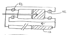
이제 또 다른 대안적 실시예에서 도 8f를 참조하면, 장치(10")는 통상적으로 본 발명이 사치성 시계 시장에서 위치하는 경우에서와 같은, 모든 전자 장치를 제외하게 만들어질 수 있다. 그러한 실시예에서, 동력원(22")은 회전 속도가 특징 기간을 가지는, 진자와 같은 레귤레이터 또는 진동하는 디스크(74)(예컨대, 밸런시어/터비온)에 의해 제어되는, 기어 트레인(72)에 동력을 공급하는 시계 스프링(70)을 감는 진동하는 덩어리로부터의 무브먼트일 수 있다. 메커니즘(76)에 의해 생성된 회전 운동은 나사(80)에 의한 선형 운동으로 변환된다. 이러한 나사(80)는 도 8a 내지 도 8e에 도시된 바와 같이 유체(28)를 구동하는 플런저(32")를 구동하고, 이 경우 밸브(82)들은 저장기(12)에서의 원하는 유체 무브먼트를 초래하기 위해 열리거나 닫힌다. 화살표(84)는 플런저(32")의 무브먼트의 방향을 보여준다. 도 8a에서, 표시기 저장기(12)는 비어 있다. 플런저(32)가 화살표의 방향으로 우측으로 전진함에 따라, 표시기에서의 유체(28)는 좌측으로 전진한다. 밸브(82)들의 라인들과 위치들이 이러한 원하는 유체 흐름을 허용한다는 점을 주목하라. 도 8b 및 도 8c는 좌측으로의 표시기에서의 유체의 지속되는 전진을 보여준다. 도 8d 및 도 8e는 낮(day)을 보여주기 위해 좌측으로의 공기의 전진을 보여준다.Referring now to FIG. 8F in yet another alternative embodiment, the
유체가 없는 실시예에서는, 스케일 장치에서의 시간을 표시하기 위해, 나머지 루프와 대조되는 표면(예를 들면 착색된)을 가지고 폐쇄된 루프로서 나삿니가 있는 로드가 형성될 수 있다. 굽힘 점(bend point)들에서 절단된 디보트(divot)들을 갖는 착색된 리드(colored reed) 형태는 저장기의 길이를 따라 작동되어 움직이는 액체와 유사할 수 있다.In a fluid-free embodiment, a threaded rod may be formed as a closed loop with a surface (eg colored) that contrasts with the rest of the loops to indicate time in the scale device. A colored reed shape with divorts cut at bend points can be similar to a liquid that operates and moves along the length of the reservoir.
저장기(12')는 임의의 원하는 모양으로 형성된 투명 또는 반투명 재료, 또는 투명 및 반투명 재료의 혼합물로 만들어질 수 있다. 그것은 플라스틱, 고무, 실리콘으로 만들어질 수 있다.The reservoir 12' may be made of a transparent or translucent material formed in any desired shape, or a mixture of transparent and translucent materials. It can be made of plastic, rubber, or silicone.
대안적인 실시예에서, 위치 센서(60) 대신에, 금속과 같은 전도성 재료로 만들어진 전도성 와이어(미도시)가 전술한 바와 같이, 저장기(12')에서 유체에 그것의 길이의 적어도 일부분을 따라서 노출된다.In an alternative embodiment, instead of the
그러므로 전도성 와이어는 저장기에서 임의의 유체와 접촉한다. 와이어와 접촉하는 유체가 저장기에서 퍼 올려짐에 따라 와이어는 그것의 길이에 따른 가변 전기 저항을 사용하여 눈금이 정해질 수 있으며, 와이어에서 측정된 전기 저항이 눈금이 정해진 바와 같이, 측정된 값에 대응하는 것과 일치할 때까지 유체가 퍼 올려진다. 표시기(10)의 눈금 매기기는 가변 저항 측정값들을 저장기의 길이를 따라 존재하는 위치들을 비교함으로써 수행되고, 그러한 위치들은 대응하는 측정된 값을 나타내기 위해 스케일로 마킹된다.Therefore, the conductive wire contacts any fluid in the reservoir. As the fluid in contact with the wire is pumped from the reservoir, the wire can be scaled using a variable electrical resistance along its length, and the electrical resistance measured at the wire is scaled to the measured value. The fluid is pumped up until it matches the corresponding one. The grading of the
이제 도 9를 참조하면, 본 발명의 직물 적용예가 도시된다. 이러한 적용예의 목표는 재료에서 바느질될 수 있는 본 발명의 장치를 제공하는 것이다. 실행 가능한 실시예는:Referring now to Figure 9, an example of fabric application of the present invention is shown. The goal of this application is to provide a device of the invention that can be sewn from material. A feasible embodiment is:
- 저장기에 분자 사슬 또는 형광성 마이크로 LED들이 포함되는 것;-The storage of molecular chains or fluorescent micro LEDs;
- 절연 재료로 만들어진 저장기;-Reservoir made of insulating material;
- 타임 피스(time piece) 구현을 위해, 적어도 12×60=720의 배치(placing)를 허용하는 거리에서 저장기의 길이를 따라 놓인 모듈 또는 마이크로 LED들;-For time piece implementation, modules or micro LEDs placed along the length of the reservoir at a distance that allows at least 12×60=720 placement;
- 소스(R)에서 그리고 그라운드로의 연결이 이루어지는 것;-The connection from source R to ground is made;
- R이 T의 전압에 도달할 때 LED들이 광을 방출하는 것(형광 또는 인광, 광택 유리(shiny glass) 타입);-LEDs emit light when R reaches the voltage of T (fluorescent or phosphorescent, shiny glass type);
- 전력원(S)에 의해 전압(R)이 제공되는 것;-The voltage R is provided by the power source S;
- 전기 소스(S)가 전기 저항(R)에는 의존적이지만 분자들 또는 형광 마이크로 LED들(M)의 소모에는 독립적인 전압 레벨(R)을 유지하는 것;-The electric source S is dependent on the electrical resistance R, but maintains an independent voltage level R for consumption of molecules or fluorescent micro LEDs M;
- 인가된 전압이 T 미만인 한 형광 분자들(M)이 무한 저항을 가지고 설정된 전압 레벨이 인가되자마자 형광성이 되는 것; 및-As long as the applied voltage is less than T, the fluorescent molecules (M) become fluorescent as soon as the set voltage level with infinite resistance is applied; And
- 소스(S)에 의해 R에 전달된 전압이 측정된 값(G)의 함수로서 변하는 것을 포함한다.-The voltage transmitted to R by the source S is changed as a function of the measured value G.
유연하게 유지되는 것은 LED들의 체인(chain)으로, 점등되거나 함께 또는 파장(wave)들을 통해 꺼지지만 측정된 값을 나타내기 위한 것은 아니다. 그것은 텍스타일 항목(textile item)에 통합될 수 있는 스레드(thread)(밀리미터 정도의 작은 직경을 갖기 때문에)와 같이 정교하고 유연할 수 있고, 방수성을 가지며, 세척 가능하다는 것 등과 같을 특징이 있다.What remains flexible is a chain of LEDs, which light up or turn off together or through waves, but are not intended to represent the measured value. It is characterized by being elaborate and flexible, waterproof, washable, etc., such as a thread (because it has a diameter as small as a millimeter) that can be incorporated into a textile item.
또 다른 실시예에서, 유체는 전기습윤이라고 부르는 프로세스에 의해 디스플레이 내에 옮겨질 수 있다. 전기습윤은 도 10a 및 도 10b에 나타낸 바와 같이, 일반적으로 소수성 표면이 그 특성을 잃고 친수성이 되는 현상이다. 도 10a는 전극에 인가된 전압이 있는 액적(droplet)을 보여준다. 도 10b는 전극에 인가된 전압이 없는 액적을 보여준다.In another embodiment, the fluid can be transferred into the display by a process called electrowetting. Electrowetting is a phenomenon in which a hydrophobic surface generally loses its properties and becomes hydrophilic, as shown in FIGS. 10A and 10B. 10A shows droplets with a voltage applied to an electrode. 10B shows droplets with no voltage applied to the electrodes.
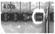
액추에이터를 만들기 위해 사용된 상이한 층들의 개략적인 세부도와 함께 전기습윤 디스플레이의 개략도가 도 11에 도시된다. 도 12a 내지 도 12d는 전극 피치가 1[㎜]이고, 높이가 400[㎛]인 실리콘 오일에서의 물의 액적의 변위를 수반하는 테스트로부터의 사진들을 보여준다.A schematic diagram of an electrowetting display with schematic details of the different layers used to make the actuator is shown in FIG. 11. 12A-12D show photographs from a test involving displacement of droplets of water in silicone oil with an electrode pitch of 1 [mm] and a height of 400 [µm].
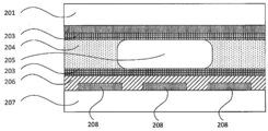
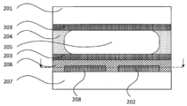
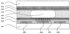
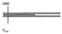
유체(205)의 액적들은 새로운 위치로의 병진운동(translation)을 얻기 위해 움직여지고 디스플레이를 움직이게 한다. 그 기능성은 시간과 같은 측정된 값을 나타내는 궁극적인 목표를 가질 수 있다. 그것은 표시에 의해 참조될 수 있다. 도 13은 상이한 층들을 갖는 전기습윤 디스플레이의 세부 개략도이다. 그것은 튼튼하거나 유연할 수 있는 상부 플레이트(201)로 구성되고, 그러한 상부 플레이트(201) 상에는 공통 전극(202)이 배치되며, 상이한 섹션들로 구성될 수 있는 얇은 전도성 층이 존재한다. 표면은 친화성이 결여된 표면 거동을 나타내는 코팅(203)에 의해 처리된다. 이들 요소들 모두는 아래에 있는 것을 보일 수 있게 하기 위해 투명하거나 반투명하거나 심지어 착색될 수 있다. 그것들은 가변적인 두께 또는 구조를 가질 수 있다.The droplets of
하부 플레이트(207)는 전기적으로 전도성인 제어 전극(208)들이 증착되고 구성되는 튼튼하거나 유연한 기판이다. 이들 제어 전극들은 친화성이 결여된 코팅(203)이 증착되는 유전 층(dielectric layer)(206)에 의해 전기 절연된다. 하부 플레이트(207)와 그것의 고유 층들은 투명하고, 반투명하며, 착색되고, 부분적으로 불투명하고, 불투명한 것을 포함하는 임의의 시각적 양태를 가질 수 있다. 그것들은 가변적인 두께 및 구조를 가질 수 있다.The
코팅(203)은 도 13에 도시된 디스플레이에서 선택적(optional)인데, 이는 유체들(204, 205)에서의 첨가제들이 유체들(204, 205)을 포함하는 저장기의 표면들과 친화성이 결여된 기능을 취할 수 있기 때문이다. 일부 경우들에서는, 유체(205)와 공통 전극(202) 사이에 전기적 접촉이 보장되고, 그렇지 않으면 전기 절연된다.The
유체(205)는 전기습윤 프로세스에서 능동 액체(active liquid)이다. 이 유체(205)는 저장기에서 제1 유체(205)에 의해 좌측 공간을 채우는 것으로 생각되는 수동 유체(204) 내의 볼 수 있는 별도의 국면(phase)을 구성한다. 유체(204)는 액체 또는 기체일 수 있다. 유체들(204, 205) 모두는 투명, 반투명, 착색된, 부분적으로 불투명한, 그리고 불투명한 것을 강한 대조가 그것들을 서로 구별하는 것을 허용하는 한, 포함하는 임의의 시각적 양태들을 가질 수 있다. 유체(205)의 하나 또는 여러 액적들은 시스템에 포함될 수 있다. 유체들 모두는 예컨대, 저장기, 채널 또는 튜브에 포함된다.
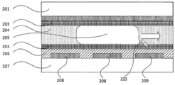
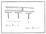
도 14는 유체(205)가 번개 기호(225)로 표시되는 전기장 하에서 어떻게 효율적으로 반응하고 다른 제어 전극(208)과 유사한 제어 전극(209)의 전기적 활성화에 의해 어떻게 적용되는지를 도시한다. 결과적으로, 하부 플레이트(207)의 표면 위의 유체(205)의 접촉각과 그것의 고유 층들은 모세관 효과에 의해 인력을 유도하여 변화한다. 이러한 인력은 유체(205) 액적의 움직임을 야기한다.14 shows how fluid 205 reacts efficiently under the electric field indicated by
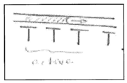
도 15는 전기습윤 효과에 의해 유체들이 옮겨지는 디스플레이의 상이한 구성요소들을 구현하는 또 다른 방식을 기술한다. 하부 플레이트(211)는 공통 전극(210)이 채널의 벽들에 놓인 2개의 섹션들로 분할되는 채널을 형성하도록 구성된다. 상부 플레이트(201)의 표면은 채널을 폐쇄하지 않는다. 코팅(203)은 액적이 채널에 머무르고 따라서 하부 플레이트(210)와 상부 플레이트(201)에 의해 형성된 얇은 공간에서 액적을 끌어내는(drag out) 모세관 효과를 회피하기 위해 모든 곳에 배치된다. 도 16은 단면의 위치가 표시되는 도 15의 구현예의 수직 단면도이다. 제어 전극(208)들은 채널을 따라 놓이고 공통 전극(210)들은 양측에서 채널을 따라 놓인다.15 describes another way to implement different components of the display where fluids are transferred by the electrowetting effect. The
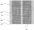
도 17은 전기습윤 효과에 의해 유체들이 옮겨지는 디스플레이의 상이한 구성요소들을 구현하는 또 다른 방식을 보여준다. 공통 전극(202)은 하부 플레이트(207) 상의 제어 전극(208)들을 따라 놓인다. 여기서 도 13 내에서와 같이 번호가 매겨지고 기술된 모든 층들은 이 구현예에서 동일한 기능을 가진다. 그러한 경우, 능동 유체(205)의 액적은 유전 층(206)에 의해 공통 전극(202)으로부터 격리된다(도 17 참조).17 shows another way to implement different components of the display where fluids are transferred by the electrowetting effect. The
도 18은 여러 섹션으로 나누어질 수 있는 공통 전극(202)의 구조의 상세한 부분들을 강조한다. 이 경우, 공통 전극(202)은 제어 전극(208)들을 따라 놓인 연신된 전극이다. 유체(205)의 액적은 전극들의 모든 종류들에 걸쳐 펼쳐진다.18 highlights details of the structure of the
도 19는 액적(224)의 모양을 가지는 유체의 변위를 제어하는 방법을 설명하는 A로부터 F까지의 스테이지들을 갖는 시퀀스(sequence)를 보여준다. 유체는 전술한 유체(205)와 유사하다. 유체(224)의 액적은 그것에 전압이 공급될 때 인접하는 제어 전극(223)들까지 움직일 수 있다고 가정하기 위해 제어 전극(223)들보다 약간 더 크다. 이 전압은 DC 타입 또는 AC 타입일 수 있다. 스테이지 A에서 액적은 정지 상태인데, 이는 어떠한 제어 전극(223)도 활성화되지 않았기 대문이다. 이 유체는 번개 기호(225)에 의해 도시된 것처럼 부근의 제어 전극이 활성화되기 때문에 스테이지 B에서 움직인다. 액적이 강력한 평형 상태(energetic equilibrium)(이는 그것이 활성화된 제어 전극(223)을 완전히 덮어야 한다는 것을 반드시 의미하지는 않는다)에 도달할 때까지 변위가 일어난다. 도 19에 도시된 것처럼, 그것은 스테이지 C에서 활성화된 제어 전극(223)을 덮는다. 스테이지 D에서는 프로세스가 스테이지 E와 스테이지 F에서 기술된 그 다음 인접한 제어 전극(223) 위에서 움직이기 위해 새로운 위치에서 다시 시작한다. 제어는 액적을 임의의 방향으로 움직일 수 있다. 유체의 여러 액적들의 경우, 그것들은 독립적으로 제어될 수 있다. 또, 도 19는 스테이지들(G 내지 N)을 갖는 시퀀스들을 보여준다.FIG. 19 shows a sequence with stages A through F illustrating how to control the displacement of a fluid having the shape of a
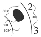
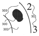
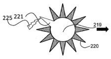
도 20a 및 도 20b는 전기습윤 효과를 이용하는 디스플레이를 구현하는 또 다른 방식을 보여준다. 도 13에 도시된 유체(205)와 동일한 성질들을 보여주는 액적은 병진운동하지 않지만 유체의 움직임은 액적의 변형을 일으킨다. 제어 전극(220)들은 이러한 특별한 실시예에서 별의 12개의 가지(branch)들을 형성하고, 그러한 가지들 각각이 활성화될 수 있다. 액적 중심(219)은 밑에 놓인 제어 전극에 의해 능동적으로 붙들려질 수 있거나 액적을 이러한 영역에서 고정시키기 위해 적절한 표면 처리로 수동적으로 붙들려 있을 수 있다. 스테이지 A에서, 별 가지(221)는 액적의 변형을 포함하는데, 이는 아래의 그것의 제어 전극(220)이 번개 기호(225)에 의해 도시된 것처럼 활성화되었기 때문이다. 스테이지 B에서는 액적의 부분을 끌어당기고 따라서 변형을 변경하기 위해 또 다른 별 가지(222)가 활성화된다. 여기서, 액적 변형이 접촉하게 되는 인접한 제어 전극(220)을 반드시 활성화할 필요는 없다. 새로운 활성화된 제어 전극(220)과 접촉해야 하는 것은 액적 중심(219)이다. 액적 변형의 이러한 원리는 액적을 살아 움직이는 것처럼 하게 하고 만약 관련 있다면 표시에 의해 참조될 수 있는 측정된 값을 나타낸다. 또, 도 20c 내지 도 20q는 스테이지들(C 내지 Q)을 갖는 시퀀스를 보여준다.20A and 20B show another way to implement a display utilizing the electrowetting effect. The droplet showing the same properties as the fluid 205 shown in FIG. 13 does not translate, but the movement of the fluid causes the droplet to deform. The
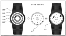
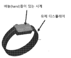
디스플레이의 특별한 구현예는 양호한 콘트라스트(contrast)를 가지기 위해 유체(205)가 착색되어 유체의 액적을 사용자에게 보일 수 있게 하는 점을 제외하고 도 13에 도시된 층들 및 유체들이 투명할 때의 경우이다. 도 21은 손목 시계(212)에 관한 이러한 실시예를 기술한다. 그러한 특별한 구현예에서는 액적(214)에 관한 시간(hour)들 및 액적(213)에 관한 분(minute)들을 나타내는 2개의 액적들이 존재한다. 원들(215, 216)은 사용자에 대해서는 보일 수 없고, 그것들은 단지 액적들이 따르는 경로(path)를 보여준다. 디스플레이의 투명성 덕분에, 사용자가 도 21에 도시된 것처럼 사용자의 장치(218)를 커스터마이즈하는 것을 허용하는 상호 교환 가능한 표시(217)를 가지는 것이 가능하다.A particular implementation of the display is when the layers and fluids shown in FIG. 13 are transparent, except that the fluid 205 is colored to have a good contrast so that droplets of the fluid are visible to the user. . 21 describes this embodiment of a
또한, 2개의 실시에들이 용량성 센서를 사용하는 전기습윤 현상을 적용한다.In addition, two embodiments apply the electrowetting phenomenon using a capacitive sensor.
도 22를 참조하면, 제1 용량성 센서 실시예에서는, 액체 레벨이 전체 튜브에 걸쳐 측정된 정전 용량의 아날로그 값으로부터 추론되는 단일 전극이 사용된다. 이러한 실시예는 더 간단한 전자 회로의 사용을 허용한다. 하지만, 환경 파라미터들의 주어진 영향을 교정하는 것은 더 어렵다.Referring to FIG. 22, in the first capacitive sensor embodiment, a single electrode is used in which the liquid level is deduced from the analog value of the capacitance measured over the entire tube. This embodiment allows the use of simpler electronic circuits. However, it is more difficult to correct the given impact of environmental parameters.
도 23을 참조하면, 제2 용량성 센서 실시예에서는, 예를 들면 각각의 시간 단계(time step)마다 하나씩 144개의 전극들을 사용하여 디지털 값으로서 액체 레벨이 결정된다.Referring to Fig. 23, in the second capacitive sensor embodiment, the liquid level is determined as a digital value using, for example, 144 electrodes, one for each time step.
위 솔루션은 제1 용량성 센서 실시예에서처럼 환경 파라미터들에 의해 영향을 받지 않게 매우 튼튼하다. 그것에 대한 한 가지 이유는 유체(205)의 액적 아래의 유전층(206)의 영역이 매우 용량성이라는 사실에 있다.The above solution is very robust so as not to be affected by environmental parameters as in the first capacitive sensor embodiment. One reason for that lies in the fact that the region of
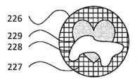
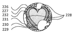
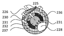
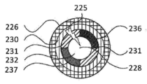
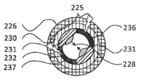
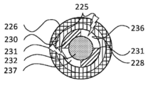
이어지는 4개의 실시예들에서, 애니메이션 목적들을 위한 전기습윤 유체 작용이 적용된다. 그것들의 구조물(construct)은 도 14에서의 전기적 활성화뿐만 아니라 도 13에 기술된 것과 동일한 방식(scheme)을 따른다. 특히, 그것들은 2개의 섞이지 않는 유체들을 포함하고, 그것들 중 하나는 참조 번호 228로 표시되어 있다.In the following four embodiments, electrowetting fluid action for animation purposes is applied. Their construction follows the same scheme as described in FIG. 13 as well as the electrical activation in FIG. 14. In particular, they contain two immiscible fluids, one of which is denoted by
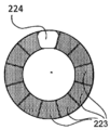
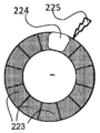
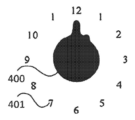
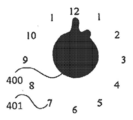
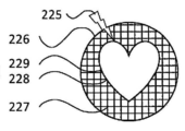
도 24a 내지 도 24c를 참조하면, 제1 기본 애니베이션 원리에서, 전기습윤 디스플레이는 하나의 심미적 모양, 이 경우에서는 심장을 나타내기 위해 설계되는 하나의 제어 전극(229)으로 이루어진다. 그것은 반투명하거나 불투명하지만 우선적으로는 애니메이션에서 놀라운 효과를 제공하기 위해 투명하다. 단계(A)(도 24a에 도시된)에서는 유체 액적(228)이 저장기(226)에서 자유롭게 떠돌아다닌다. 영역(227)은 유체 액적(228)이 강제 없이 움직이도록 제어 전극(229) 위에서와 동일한 방식으로 코팅된다. 만약 제어 전극(229)이 투명하자면, 단계(B)(도 24b에 도시된)에서의 그것의 전기적 활성화는 놀라운 효과를 유도하는데 이는 액적 변형이 예상되지 않기 때문이다. 그러한 변형은 단계(C)(도 24c에 도시된)에서 도시된 것처럼 제어 전극(229)의 모양에 따라 새로운 안정한 상태에서 끝난다.24A-24C, in the first basic animation principle, the electrowetting display consists of one aesthetic shape, in this case one
유체 액적(228)이나 임의의 분리된 유체 액적을 더 효과적으로 작용하게 하는 것은 제어 전극(229) 상으로 올바르게 이동시키기 위해 제어 전극과 중첩되어야 한다. 하나의 제어 전극만을 가지는 것은 제어 시스템이 활성화된 전원으로 감소될 수 있는 가장 간단한 구현예이다. 하지만 유체 애니메이션을 증대시키기 위해 더 복잡한 구성이 만들어질 수 있다.Making the
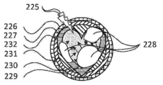
도 25를 참조하면, 전기습윤 디스플레이는 임의의 분리된 액적들을 모을 수 있는 시스템을 구현한다. 단계(A)(도 25a에 도시된)에서는, 유체(228)의 모든 부분들이 저장기(226)에서 자유롭게 떠다닌다. 실질적으로 저장기(226)의 전체 표면은 유체의 움직임에 어떠한 제한도 제공하지 않기 위해 처리된다. 이러한 특별한 구현예에서는, 4개의 동심 제어 전극들(229 내지 232)이 제공된다. 다시, 그것들은 불투명하거나 반투명할 수 있지만 놀라운 효과를 제공하기 위해 우선적으로 투명할 수 있다. 제어 전극들이 표면의 일부를 덮는 한 반드시 동심 구조를 가질 필요는 없고, 가령 유체(228)의 임의의 액적이 임의의 제어 전극들 중 적어도 일부와 중첩될 것이다.Referring to Figure 25, the electrowetting display implements a system capable of collecting any separated droplets. In step (A) (shown in FIG. 25A ), all portions of
이러한 구현예에서의 순서는 단계(B)(도 25b에 도시된)에서 기술된 제어 전극들(229 내지 232)의 활성화에 의해 시작된다. 그것은 놀라운 효과를 발생시키는데 이는 유체(228)의 액적이 예기치 않게 움직이기 때문이다. 단계(C)(도 25c에 도시된)에서, 유체(228)의 액적은 활성화된 제어 전극들(229 내지 232)과 비활성화된 영역(227) 위에 있는 액적 가장자리들 사이의 접촉 각도의 차이 덕분에 모세관 효과에 의해 비활성화된 영역(227)을 떠나기 위해 움직인다. 그러한 상태로부터, 순서는 단계적으로 단계(D)(도 25d에 도시된)에서 외부의 것(232), 단계(E)(도 25e에 도시된)에서의 제어 전극(231), 및 단계(F)(도 25F에 도시된)에서의 제어 전극(231)으로부터 모든 제어 전극들을 디스에이블시키기 시작한다. 각 단계에서, 유체(228)의 액적들은 단계(C)에서 설명된 것과 동일한 이유들 때문에 중심 쪽으로 움직인다. 단계(F)에서는, 액적들이 서로 접촉되고 함께 합해져서 단계(G)(도 25g에 도시된)의 끝에서 최종 제어 전극(229)에 의해 규정된 모양을 형성한다. 액적이 합해지는 것은 임의의 단계에서 일어날 수 있는데, 이는 그것이 각 액적(228)의 초기 위치와 변형에 의존적이기 때문이다. 동심 원리는 그 순서가 제어 전극들의 구조와 관련하여 규정될 수 있기 때문에 액적들을 모으는 유일한 가능한 수단은 아니다.The sequence in this implementation is initiated by activation of the control electrodes 229-232 described in step B (shown in Fig. 25B). It creates an amazing effect because the droplets of
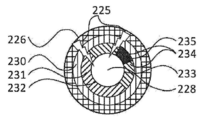
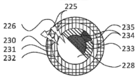
도 26을 참조하면, 전기습윤 디스플레이는 능동 유체에 의해 둘러싸인 수동 유체의 제어된 에워싸인 부분을 얻는 방법을 구현한다. 이 방법은 유체(228)의 액적에 의해 점유된 구역을 제외하고는 저장기(226)의 전체 영역을 본질적으로 덮는 제2 유체를 에워싸는 적어도 하나의 공동을 갖는 액적의 형태를 만든다. 도 24에서 기술된 다른 구현예와 같이, 저장기의 실질적으로 전체 표면은 균일하게 처리되었고 제어 전극들(230 내지 235)은 불투명하거나 반투명할 수 있지만 바람직하게는 투명하다. 단계(A)(도 26a에 도시된)에서는, 액적이 저장기(226)에서 자유롭게 떠다닌다. 단계(C)(도 26c에 도시된)에서 기술된 바와 같이 제어 전극들(232, 233) 위에서 디스플레이의 중심으로 유체(228)의 액적을 움직이기 시작하기 위해 모든 제어 전극들(230 내지 235)이 활성화되는 단계(B)(도 26b에 도시된)에서 놀라운 효과가 유발된다. 이러한 순서에서는 도시되지 않은 중간의 단계들이 존재하는데 이는 그것들이 도 25에서 기술된 것과 유사하기 때문이다. 단계(D)(도 26d에 도시된)에서는 제어 전극(231, 232) 위에서 하나의 반원 상에서 액적이 움직인다. 전술한 것은 구멍 형성을 위한 초기 준비를 기술한다. 다시 말해, 전술한 순서는 수동 유체(다른 애니메이션들에 관한 것처럼)에 의해 둘러싸인 능동 유체의 고리(ring)를 발생시키고, 그러한 원의 내부는 또한 수동 유체로 채워져 있다.Referring to Figure 26, an electrowetting display implements a method of obtaining a controlled enclosed portion of a passive fluid surrounded by an active fluid. This method forms a droplet with at least one cavity surrounding a second fluid that essentially covers the entire area of
단계(E)(도 26e에 도시된)에서는, 제어 전극(234)들이 활성화되고 액적이 편자 모양을 취하게 하기 위해 가운데 제어 전극(232)이 디스에이블된다. 액적은 여전히 그것의 비활성 상태에도 불구하고 전극(232)의 부분을 덮는다. 최종 제어 전극(235)은 하나의 섹션이 유체(228)에 의해 덮이지 않게 하기 위해 디스에이블되어, 제2 유체가 미래의 구멍 안쪽으로 흐르는 것을 허용한다. 다른 한편으로, 유체(228)는 활성화된 전극들 쪽으로 끌어 넣어져서 다른 유체가 제어 전극(231)을 덮는 것을 허용한다. 단계(F)(도 26f에 도시된)에서, 최종 제어 전극(235)이 활성화되고, 유체(228)의 액적을 끌어당겨 그것의 2개의 암(arm)들로 합쳐지게 하고 제어 전극들(232, 233) 위에서 안쪽에 제2 유체의 구멍을 갖는 그것의 최종 모양을 취한다.In step E (shown in FIG. 26E ), the
능동 유체의 액적에서 수동 유체들의 공동들의 모양을 형성하는 다른 구현예들이 생각될 수 있다. 그것은 제어 전극들 구조와 제어 순서에 의존적이다.Other embodiments are contemplated to shape the cavities of passive fluids in a droplet of active fluid. It depends on the control electrodes structure and control order.
도 27을 참조하면, 전기습윤 디스플레이는 유체(228)의 액적이 2개의 부분으로 분리되는 애니메이션을 구현한다. 단계(A)(도 27a에 도시된)에서, 유체(228)의 액적은 저장기(226) 전체에 걸쳐 표면 처리의 균일성 덕분에 자유롭게 떠다니고 움직인다. 도 24에 의해 나타낸 실시예에서처럼, 제어 전극은 불투명하고, 반투명할 수 있지만 우선적으로는 모든 제어 전극들(230 내지 232 및 236과 237)이 디스플레이의 가운데에서 액적을 끌어당기기 위해 활성화되는 단계(B)(도 27b에 도시된) 동안에 놀라운 효과를 제공하기 위해 투명할 수 있다. 도 25에 의해 도시된 것과 유사한 순서 후에, 액적은 단계(C)(도 27c에 도시된)에서 가운데(232)에서 제어 전극 위에서 끝난다. 그런 다음 액적은 단계(D)(도 27c에 도시된)에서 제어 전극(236, 237)의 활성화에 의해 2개의 반대 방향으로 끌어당겨진다. 유체(228)의 액적은 양 전극들의 방향으로 변형되고 결국은 2개의 활성화된 전극(236, 237)을 덮을 2개의 독립되고 작은 액적들로 나누어진다. 잘 작용하기 위해, 이러한 프로세스는 제어 전극들의 설계, 제어 시퀀스 및 유체(228)의 액적의 사이즈 사이에서 미세하게 조정되어야 한다.Referring to FIG. 27, the electrowetting display implements an animation in which droplets of
장치는 ISO 764, ISO 1413 및 ISO 2281의 일반적인 시계 요구 사항들을 충족할 것이다.The device will meet the general clock requirements of ISO 764, ISO 1413 and ISO 2281.
도 28a 내지 도 28d는 본 발명의 요소들의 요구 사항들을 고려한 것을 보여주는 표들이다.28A-28D are tables showing consideration of the requirements of the elements of the present invention.
도 29a는 URS(도 3 참조) 후의 원형을 보여주고 도 29b는 관련된 블랙 박스를 보여준다.FIG. 29A shows the prototype after URS (see FIG. 3) and FIG. 29B shows the associated black box.
도 29c는 국면 I에 관한 본 발명의 설계 특정 요구 조건들을 보여준다.29C shows the design specific requirements of the present invention for phase I.
프로젝트의 본래의 블록도가 도 30a에 나타나 있다. 그것의 부품들 중 일부는 명확히 스퀴글(Squiggle) 드라이브의 적용예 쪽으로 향해 있다.The original block diagram of the project is shown in Figure 30A. Some of its parts are clearly pointing towards the application of Squiggle drives.
도 30b에는 일반화된 블록도가 나타나 있다. 동일한 도면에서, 이러한 프로젝트의 제1 국면의 범주의 윤곽이 그려져 있다. 목표는 그것의 직접적인 의존성으로 액추에이터를 개발하는 것이고, 이는 저장기와 감압 챔버이다.30B shows a generalized block diagram. In the same drawing, the categories of the first phase of this project are outlined. The goal is to develop an actuator with its direct dependence, which is a reservoir and a decompression chamber.
센서가 액추에이터의 설계와 제어에서 중요한 역할을 하기 때문에, 그것은 또한 이러한 제1 국면의 범주에 있다.Because the sensor plays an important role in the design and control of the actuator, it is also within the scope of this first phase.
도 30c에는 장치의 간결한 기능 분석이 나타나 있다. 이 도면에서, 청색으로 테를 두룬 기능들이 프로젝트의 제1 국면에서 처리될 것이다.30C shows a concise functional analysis of the device. In this figure, the blue bordered functions will be addressed in the first phase of the project.
이 섹션에서, 국면들 인터페이스에 관한 솔루션들, 액체의 변위 및 액체 위치 함수들의 탐지가 처리될 것이다.In this section, solutions on the phases interface, detection of liquid displacement and liquid position functions will be handled.
국면들 인터페이스는 엄밀히 말하자면 함수(function)가 아니다. 그럼에도 불구하고, 액추에이터의 설계시 중요한 영향력을 갖기 때문이다.Aspects Interface is not strictly a function. Nevertheless, it has an important influence in the design of the actuator.
국면들 인터페이스에 관한 솔루션들 중 3가지가 도 31a에 나타나 있다.Three of the solutions for the phases interface are shown in FIG. 31A.
이들 솔루션들은 도 31b에서 논의된다.These solutions are discussed in FIG. 31B.
액체-진공(액체-증기) 국면 인터페이스에 관한 액체들의 기재Description of liquids on the liquid-vacuum (liquid-vapor) phase interface
소위 액체-진공 국면들 인터페이스는 실제로 액체-증기 인터페이스가 되고, "빈(empty)" 공간이 대신 그것의 증기압에서 증발된 액체로 채워져 있다. 증기압은 온도의 함수로서 상이한 액체들에 관해 도 31c에 나타나 있다. 이 값은 온도에 관하여 큰 변동을 가지는 것이 분명하다. 예컨대:The so-called liquid-vacuum phases interface actually becomes the liquid-steam interface, and the "empty" space is instead filled with liquid evaporated at its vapor pressure. Vapor pressure is shown in FIG. 31C for different liquids as a function of temperature. It is clear that this value has a large fluctuation with respect to temperature. for example:
·-10[℃]에서의 양의 압력을 가지기 위해, 염화메틸로 압력이 40[℃]에서 8[bar]에 도달하게 된다.In order to have a positive pressure at -10 [°C], the pressure with methyl chloride reaches from 40 [°C] to 8 [bar].
·프로판의 압력은 훨씬 더 높은 레벨들로 상승하게 된다.Propane pressure rises to even higher levels.
이는 액추에이터가 그것이 40[℃]에서 면하게 되는 압력에 관해 치수가 정해져야 함을 의미한다. 그러므로 대부분의 그것의 작동 범위에 걸쳐 필요한 크기 이상이 되게 되고 장치가 보다 높은 온도들까지 일시적으로 가열되어 고장의 위험이 존재하게 된다.This means that the actuator must be dimensioned with respect to the pressure it encounters at 40 [°C]. Therefore, over most of its operating range, it becomes more than the required size and the device is temporarily heated to higher temperatures, and there is a risk of failure.
다음과 같은 결론이 이루어진다:The following conclusions are made:
이들 이유들로 인해, 액체-증기 압력이 회피되어야 한다.For these reasons, liquid-vapor pressure must be avoided.
2가지 나머지 인터페이스들로부터, 액체-액체 인터페이스가 바람직한데, 이는 액체가 팽창에 덜 민감하고, 충격의 경우 기포 발생 위험이 감소하고, 메니스커스의 진행이 보다 규칙적이며, 온도 및 압력의 급격한 변화가 있는 경우 액체-기체 인터페이스에서 기포가 형성될 위험이 발생할 수 있기 때문이다.From the two remaining interfaces, a liquid-liquid interface is preferred, which makes the liquid less susceptible to expansion, reduces the risk of air bubbles in the case of impact, the meniscus progresses more regularly, and changes rapidly in temperature and pressure. This is because there is a risk of air bubbles forming at the liquid-gas interface.
액체들의 변위에 관한 솔루션들의 기재:Description of solutions regarding displacement of liquids:
도 31d에는 액체의 변위에 관한 솔루션들 중 3가지가 나타나 있다. 그러한 솔루션들은 5개의 주된 카테고리들로 모여 있다.In Fig. 31d, three of the solutions regarding the displacement of the liquid are shown. Such solutions are grouped into five main categories.
1. 피스톤 시스템들: 피스톤이 벨로즈(bellows) 저장기에 담긴 액체를 압축한다.1. Piston systems : The piston compresses the liquid in the bellows reservoir.
2. 액체에 대한 직접적인 전자기 작용: 유체 자체에 대한 전자기 작용이 액추에이터 없이 그것을 움직인다.2. Direct electromagnetic action on the liquid : The electromagnetic action on the fluid itself moves it without an actuator.
3. 펌프 시스템들: 벨로즈 저장기로부터의 액체가 디스플레이 튜브 내로 퍼 내진다.3. Pump systems : Liquid from the bellows reservoir is pumped into the display tube.
4. 열적 시스템(thermal system)들: 열적 효과가 액체의 변위를 일으킨다.4. Thermal systems : The thermal effect causes displacement of the liquid.
5. 화학적인(chemical): 액체는 화학 반응에 의해 변위된다.5. Chemical : The liquid is displaced by a chemical reaction.
카테고리들(1 내지 4)은 도 32a 내지 도 32d에서 논의된다.Categories 1-4 are discussed in FIGS. 32A-32D.
액체 변위 시스템들에 관한 평가 기준은 도 33에 도시된다.The evaluation criteria for liquid displacement systems are shown in FIG. 33.
도 33에는 순위(ranking) 기준이 나타나 있다. 순위는 각각의 고려된 순위 기준에 관해 1, 3 또는 9의 등급(grade)으로 모든 솔루션이 할당되는 1-3-9 방법을 사용하여 행해진다. 순위 기준 자체들은 1, 3 또는 9인 가중치(weight)를 가진다. 이러한 식으로, 임의의 기여(contribution)가 1과 81 사이의 값을 솔루션의 총 등급으로 가져갈 수 있다.33 shows the ranking criteria. The ranking is done using 1-3-9 methods where all solutions are assigned with a grade of 1, 3 or 9 for each considered ranking criterion. The ranking criteria themselves have a weight of 1, 3 or 9. In this way, any contribution can take a value between 1 and 81 into the total rating of the solution.
환경 파라미터들에 대한 견고성(robustness)은 여기에 디스플레이되지 않는데, 이는 그것이 작용, 인터페이스의 타입, 및 감지(sensing)의 결합에 의해 규정될 것이기 때문이다.Robustness to environmental parameters is not displayed here, as it will be defined by a combination of action, type of interface, and sensing.
다음 기준은 최대 9 아래의 가중치를 부여한 우선 순위였다:The following criteria were weighted priorities of up to 9:
복잡성(complexity): 제품이 설계될 것으로 예상되는 고급 세그먼트(high-end segment)로 인해, 복잡성이 가장 중요한 기준으로 간주되지 않는다. Complexity : Due to the high-end segment the product is expected to be designed for, complexity is not considered the most important criterion.
확장성(scalability): 제품은 지금은 시계 디스플레이들을 위한 것이다. 비록 가능한 추가 적용예들이 다른 차원으로의 확장을 요구할 수도 있지만 현재로서는 중요한 기준이 아니다. Scalability : The product is now for watch displays. Although possible additional applications may require expansion to other dimensions, this is not an important criterion at this time.
수동 설정 속도: 일부 솔루션들은 임의의 속도로 수동으로 디스플레이를 설정하는 것을 허용하지 않는다. 이는 사용자가 디스플레이에 대한 사용자의 조치에 대해 즉각적인 피드백을 가지지 않기 때문에 문제가 될 수 있다. 이 기준은 지금은 3의 가중치(weighting)가 주어지지만 증가되어야 할 수도 있다. Manual setting speed : Some solutions do not allow setting the display manually at any speed. This can be a problem because the user does not have immediate feedback on the user's action on the display. This criterion is now given a weighting of 3, but may need to be increased.
비용: 다시 한번, 제품이 설계되는 고급 세그먼트로 인해 비용이 가장 중요한 기준으로 보이지는 않는다. 비용이 많이 들고 복잡한 장치는 시계 고객들의 관심을 끌 수도 있다. Cost : Once again, due to the high-end segments in which products are designed, cost is not the most important criterion. Expensive and complex devices may attract watch customers.
모든 고려된 솔루션들의 순위가 전술한 순위 기준을 가지고 도 34에 도시된다.The ranking of all considered solutions is shown in FIG. 34 with the ranking criteria described above.
5개의 선도하는(leading) 솔루션들은 다음과 같다:The five leading solutions are:
1. 스테퍼 모터 작동 나선 휠이 이 순위에서 첫 번째로 온다. 그것은 비교적 간단한 메커니즘과 알려진 액추에이터들을 사용하는 매우 간단한 솔루션이다. 게다가, 나선 휠을 그것의 기어 트레인으로부터 분리시키기 위해 기계적인 클러치를 사용하여, 표시기의 수동 설정이 매우 신속하게 행해질 수 있다. 그것의 유일한 핸디캡은 그것의 비교적 더 큰 사이즈이다. 1. The stepper motor operated spiral wheel comes first in this ranking. It is a very simple solution using a relatively simple mechanism and known actuators. In addition, by using a mechanical clutch to separate the spiral wheel from its gear train, manual setting of the indicator can be done very quickly. Its only handicap is its relatively larger size.
2. 피에조 멤브레인 펌프(piezo membrane pump)가 두 번째로 온다. 그것은 그것의 적은 사이즈, 튼튼한 설계 및 알려진 기술로 인해 양호한 순위를 가진다. 그것의 핸디캡은 상대적으로 낮은 확장성으로 인해 다른 솔루션들보다 비용이 많이들 수 있다는 것이다. 2. The piezo membrane pump comes second. It has a good ranking due to its small size, sturdy design and known technology. Its handicap is that it can be more expensive than other solutions due to its relatively low scalability.
3. 시계 메커니즘에 의해 작동된 나선 휠이 세 번째로 온다. 이 솔루션은 직설적으로 표시되고, 그러한 솔루션을 개발하는 프로젝트의 첫 번째 국면의 목적은 아니므로, 여기서는 추구하지 않는다는 점을 주목하라. 하지만 위닝(winning) 솔루션은 또한 완전히 기계적인 디스플레이서 쉽게 전환될 수 있다는 것이 주목되어야 한다. 3. The spiral wheel activated by the clock mechanism comes in third. Note that this solution is presented in a straightforward way and is not the goal of the first phase of the project to develop such a solution, so it is not pursued here. It should be noted, however, that the winning solution can also be easily switched to a fully mechanical displayer.
4. 전자기 멤브레인/피스톤 펌프가 네 번째 위치에 있다. 그것은 더 높은 사이즈의 비용으로 피에조 멤브레인 펌프의 장점들을 가진다. 4. The electromagnetic membrane/piston pump is in the fourth position. It has the advantages of piezo membrane pumps at a higher size cost.
5. 전기습윤이 다섯번 째 위치에 있다. 5. Electrowetting is in the fifth position.
5. 스퀴글 구동된 피스톤 드라이브가 다섯번 째 위치에 관해 결합된다. 이 솔루션은 그것의 높은 주파수의 피에조 액추에이터들과 그에 대한 리턴으로 전력에 대한 필요성으로 인해 더 높은 에너지 소모를 가져오는 것이 핸디캡이다. 게다가, 그러한 피에조 액추에이터들은 비용이 많이 드는 경향이 있고 완전히 확장 가능하지 않다. 마지막으로 제2 액추에이터가 구현되지 않는 한, 이 방법을 사용하면 수동 설정이 느려지게 된다. 5. The squiggle driven piston drive is engaged with respect to the fifth position. The solution is handicap, resulting in higher energy consumption due to the need for power as its high frequency piezo actuators and return to it. Moreover, such piezo actuators tend to be costly and not fully scalable. Finally, unless a second actuator is implemented, using this method will slow the manual setup.
이후 선도하는 솔루션들이 상세하게 제시된다.Leading solutions are then presented in detail.
나선 휠을 작동시키는 스테퍼 모터가 설명된다. 이러한 솔루션의 개략적 표현이 도 39a(평면도)에 나타나 있고, 도 39b(측면도)는 그러한 설정을 신속하게 행하기 위한 솔루션을 나타내고 있다. 설정을 행하기 위해, 사용자 조작 버튼은 나선 휠을 그것의 기어 트레인으로부터 분리하게 되고 전원을 끄지 않고 빠르게 설정하는 것을 허용한다. 스테퍼 모터를 포함하는 모든 구성요소들은 간단하고 잘 알려져 있다.A stepper motor that operates a spiral wheel is described. A schematic representation of this solution is shown in Fig. 39A (top view), and Fig. 39B (side view) shows a solution for quickly making such a setting. To do the setting, the user-operated button detaches the spiral wheel from its gear train and allows quick setting without turning off the power. All components, including stepper motors, are simple and well known.
피에조 멤브레인 펌프에 대해 설명한다. 도 40에는 인슐린 주입 목적을 위해 Debiotech에 의해 설계된 장치인 나노펌프/피에조 멤브레인 펌프가 나타나 있다. 이러한 특별한 장치는 펄스당 200[nl] 분배량(dispense)을 가진다. 이 제품은 SOI(Silicon On Insulator) 웨이퍼들에서 완전히 미세 기계가공되어 높은 반복성을 제공한다.The piezo membrane pump will be described. 40 shows a nanopump/piezo membrane pump, a device designed by Debiotech for insulin injection purposes. This particular device has a 200 [nl] dispense per pulse. This product is fully micro-machined in SOI (Silicon On Insulator) wafers to provide high repeatability.
게다가, 디바이스가 자체 프라이밍(self-priming)이므로, 개방 루프 조절이 가능하다: 12시간 주기가 끝나면 리턴 밸브들을 열어 저장기에서 액체가 회수될 수 있다. 그런 다음, 펌프는 그것의 배출구에 놓인 단일 용량성 센서에 의해 액체가 탐지될 때까지 활성화될 수 있다. 이 포인트 후, 다음 12시간 기간 동안 규칙적인 단계들을 제공하기 위해 펌프가 신뢰될 수 있다.Moreover, since the device is self-priming, open loop adjustment is possible: at the end of the 12 hour cycle, return valves can be opened to recover liquid from the reservoir. The pump can then be activated until liquid is detected by a single capacitive sensor placed at its outlet. After this point, the pump can be trusted to provide regular steps for the next 12 hour period.
용량성 센서는 이론상으로는 장치에 통합될 수 있다는 것을 주목하라.Note that the capacitive sensor can theoretically be integrated into the device.
나노펌프와 같은 일부 장치들은 시장에 존재하거나 개발 중에 있다.Some devices, such as nanopumps, are on the market or are in development.
전자기 멤브레인/피스톤 펌프를 설명한다. 그러한 전자기 멤브레인/피스톤 펌프 장치의 개략도가 멤브레인 펌프의 경우에 관해 도 41에 나타나 있다. 피스톤 구성도 구현 가능하다는 것이 주목할 만하다. 그러나 두 장치의 기능이 매우 유사하기 때문에 지금은 두 솔루션 모두 함께 고려된다.Describe the electromagnetic membrane/piston pump. A schematic diagram of such an electromagnetic membrane/piston pump device is shown in FIG. 41 for the case of a membrane pump. It is noteworthy that the piston configuration is also feasible. However, since the capabilities of both devices are very similar, both solutions are now considered together.
양쪽 경우에서, 압축 챔버의 부피는 변하고, 2개의 체크 밸브들이 이러한 변화에 의해 발생된 흐름이 원하는 방향으로 가는 것을 보장한다.In both cases, the volume of the compression chamber changes, and two check valves ensure that the flow generated by this change goes in the desired direction.
그러한 펌프들의 주된 장점들 중 하나는 그것들이 용적 측정(volumetric) 흐름을 발생시킨다는 것으로, 따라서 시스템이 12시간 주기마다 재교정된다면, 표시기 내의 액체의 전진은 개방-루프 시스템에 의해 제어될 수 있다.One of the main advantages of such pumps is that they generate a volumetric flow, so if the system is recalibrated every 12 hours, the advancement of the liquid in the indicator can be controlled by an open-loop system.
전기습윤에 대해 설명한다. 전기습윤은 보통 소수성 표면이 그 특성을 상실하고 친수성이 되는 현상이다. 이는 도 42a 및 도 42b에 나타나 있다. 이러한 식으로, 정렬된 여러 전극들을 가지고, 디스플레이에서 물의 액적의 변위를 제어하는 것이 가능하다.Electrowetting will be described. Electrowetting is a phenomenon where hydrophobic surfaces usually lose their properties and become hydrophilic. This is shown in Figures 42A and 42B. In this way, with several electrodes aligned, it is possible to control the displacement of the droplets of water in the display.
그러한 디스플레이의 개략도가 도 43에 나타나 있고, 액추에이터를 만들기 위해 사용된 상이한 층들의 세부 개략도도 나타나 있다. 전극보다 약간 큰 액적을 사용하여, 그러한 액적은 그것에 전류가 공급될 때 이웃하는 전극으로 이동한다.The schematic diagram of such a display is shown in FIG. 43, and a detailed schematic diagram of different layers used to make the actuator is also shown. Using droplets slightly larger than the electrode, such droplets move to neighboring electrodes when current is supplied to them.
실리콘 오일에서의 물의 액적의 변위를 수반하는 테스트로부터의 사진들이 도 44에 나타나 있다. 그 변위는 매우 신속한 것이 보여질 수 있다. 게다가, 수반된 파워는 전극들이 커패시터들로서 행동하기 때문에 비교적 낮은데, 즉 시스템에서는 어떠한 전류의 전도도 일어나지 않는다.Pictures from tests involving displacement of water droplets in silicone oil are shown in FIG. 44. The displacement can be seen to be very rapid. Moreover, the power involved is relatively low because the electrodes act as capacitors, i.e. no conduction of current occurs in the system.
아직까지 공개된 작업의 대부분은 액체 디스플레이의 경우에 액체의 기둥을 변위시키는 데 요구되는 바와 같이, 벌크의 것이 아닌 물의 액적들의 변위를 수반한다. 하지만 디스플레이 거동은 또한 도 45에 나타낸 것과 같은 단일 액적의 변위에 의해 달성될 수 있다. 이러한 경우에서의 액적은 유색 오일과 무색 오일 사이의 분리를 하기 위해 사용되고, 유색 오일은 표시 매체(indication medium)이다.Much of the work still published involves displacement of droplets of water that are not bulky, as is required to displace a column of liquid in the case of a liquid display. However, the display behavior can also be achieved by displacement of a single droplet as shown in FIG. 45. The droplets in this case are used for separation between the colored oil and the colorless oil, and the colored oil is an indication medium.
이 데이터는 전기습윤의 지금까지 예증된 능력(capability)들의 일부를 디스플레이하려고 의도된다.This data is intended to display some of the capacities so far demonstrated of electrowetting.
이제 스퀴글 구동된 피스톤을 설명한다. 도 46은 스퀴들 구동된 피스톤 변형예를 보여준다. 이 솔루션은 기존의 제품에 의존하고, 그러한 액추에이터는 예컨대 나선 휠 시스템에 적응될 수 있다.Now, the squiggle driven piston will be described. 46 shows a modified example of a squid driven piston. This solution relies on existing products, and such actuators can be adapted, for example, to spiral wheel systems.
탐지 액체 위치 솔루션들을 설명한다. 액체 위치의 탐지를 위한 솔루션들의 트리가 도 47에 나타나 있다. 3개의 큰 그룹들 중 첫 번째 그룹은 '직접적인 감지(direct sensing)'로서, 이 경우 센서는 표시지 튜브에 통합되고 액체의 위치를 직접적으로 탐지하며, 두 번째 그룹은 '개방-루프(open-loop)'로서, 이 경우에는 어떠한 센서도 사용되지 않고 에러들의 축적을 방지하기 위해 매 12시간마다 시스템이 재설정되며, 세 번째 그룹은 "간접적인 감지(indirect sensing)"로서, 이 경우 액추에이터의 위치가 추적되고, 액체 기둥의 위치가 추측된다. 게다가, 액체-기체 인터페이스와 함께 간접 센서가 사용되는 경우 온도에 대한 보상이 수행되어야 할 수 있음에 유의해야 한다.Describe the detection liquid location solutions. A tree of solutions for the detection of liquid location is shown in FIG. 47. The first of the three large groups is'direct sensing', in which case the sensor is integrated into the indicator tube and directly detects the location of the liquid, and the second group is'open-loop'. loop)', in this case no sensor is used and the system is reset every 12 hours to prevent the accumulation of errors, the third group is "indirect sensing", in this case the position of the actuator Is traced, and the position of the liquid column is guessed. In addition, it should be noted that temperature compensation may have to be performed if an indirect sensor is used with a liquid-gas interface.
액체 위치의 탐지에 관한 솔루션들은 도 48에서 논의된다.Solutions relating to the detection of liquid location are discussed in FIG. 48.
액체 감지 방법들에 관한 평가 기준은 도 49에서 논의된다.The evaluation criteria for liquid sensing methods are discussed in FIG. 49.
환경 파라미터들에 대한 감도는 예컨대 적절한 인터페이스를 선택하여 이 감도를 회피할 가능성은 없게 감지 방법이 본질적으로 민감한 경우에만 지정된다.Sensitivity to environmental parameters is specified only if the sensing method is inherently sensitive, for example, by selecting the appropriate interface and there is no possibility to circumvent this sensitivity.
개방-루프 조절뿐만 아니라 모든 고려된 간접적인 센서들에 관해서, 액체를 변위시키는 액추에이터는 용적 측정적이라는 것이 고려되는데, 즉 액추에이터의 일정한 위치는 액체 기둥의 위치에 대응한다는 것이 고려된다. 이는 어떠한 압력 발생기가 액추에이터들의 선택을 지나치지 않았기 때문에 가정으로 취해진다.For all considered indirect sensors as well as open-loop adjustment, it is considered that the actuator that displaces the liquid is volumetric, ie it is considered that the constant position of the actuator corresponds to the position of the liquid column. This is assumed as no pressure generator has passed the selection of actuators.
도 50에는 액체 레벨 센서들의 선택된 솔루션들의 순위가 나타나 있다.50 shows the ranking of selected solutions of liquid level sensors.
그 결과들은 다음과 같다:The results are as follows:
·용량성 센서는 바람직한 솔루션인데, 이는 그것이 비교적 간단한 기술에 의존하면서 액체 기둥의 위치의 신뢰 가능한 폐쇄-루프(closed-loop) 제어를 허용하기 때문이다.A capacitive sensor is a preferred solution because it relies on a relatively simple technique, allowing reliable closed-loop control of the position of the liquid column.
·간접적 감지 방법들이 두 번째로 온다. 모두 간단하지만, 어떠한 폐쇄-루프 조절도 행해지지 않기 대문에 약간 더 높은 에러들이 초래될 수 있다.· Indirect detection methods come second. All simple, but slightly higher errors can be introduced because no closed-loop adjustment is made.
·개방-루프 솔루션이 세 번째 위치에 온다. 그것은 에러를 나타낼 수 있고, 액추에이터의 스텝마다의 분배가 시간이 지남에 따라 변경되지 않도록 특별한 주의가 이루어져야 한다. 하지만, 그것의 간단함이 큰 장점이다.· The open-loop solution comes to the third position. It may indicate an error, and special care should be taken so that the distribution of each step of the actuator does not change over time. However, its simplicity is a big advantage.
이들 3가지 제1 솔루션 그룹들은 다음 섹션에서 상세하게 기술될 것이다. 저항성 센서는 상세하게 기술되지 않을 것인데, 이는 그것이 유사한 성능을 가지면서도 상당히 더 복잡한 설계를 가지기 때문이다.These three first solution groups will be described in detail in the next section. The resistive sensor will not be described in detail because it has a similar performance but a considerably more complex design.
선도하는 솔루션들의 상세한 기술Detailed technology of leading solutions
용량성 센서에 대해 설명한다. 용량성 센서의 2가지 구현예들이 가능하다. 한 가지 구현 솔루션은 단일 전극 센서로서, 이 경우 액체 레벨은 전체 튜브에 걸쳐 측정된 용량의 아날로그 값으로부터 추측된다. 또 다른 구현 솔루션은 다중 전극 센서로, 이 경우 액체 레벨은 모든 시간 단계들에 관해, 144개의 전극들을 사용하여 디지털 값으로서 결정된다.The capacitive sensor will be described. Two implementations of the capacitive sensor are possible. One implementation solution is a single electrode sensor, in which case the liquid level is estimated from the analog value of the measured capacity over the entire tube. Another implementation solution is a multi-electrode sensor, in which case the liquid level is determined as a digital value using 144 electrodes, for all time steps.
첫 번째 솔루션은 더 간단한 전자 회로를 사용하는 것을 허용하지만, 환경 파라미터들에 대한 아날로그 회로의 감도로 인해 교정하는 것이 도전적이라는 것이 입증될 수 있다. 하지만, 두 번째 솔루션은 지극히 튼튼한 솔루션이 된다. 양 솔루션들 모두는 도 51a와 도 51b에 나타나 있다.The first solution allows the use of simpler electronic circuits, but can be proved to be challenging to calibrate due to the sensitivity of the analog circuit to environmental parameters. However, the second solution is an extremely robust solution. Both solutions are shown in FIGS. 51A and 51B.
제2 솔루션의 튼튼함은, 그것의 전기습윤 솔루션과의 호환성으로 인해 바람직한 것이 되게 한다.The robustness of the second solution makes it desirable due to its compatibility with the electrowetting solution.
액추에이터 상의 유도성 센서를 설명한다. 액추에이터 상에 놓이는 유도성 센서는 이러한 코일의 인덕턴스를 측정함으로써, 코일에서의 페라이트(ferrite)의 위치를 측정한다. 그것은 도 52에 개략적으로 나타나 있다. 그러한 센서들은 이미 널리 사용중이고 매우 신뢰 가능한 결과들을 제공한다.An inductive sensor on the actuator will be described. The inductive sensor placed on the actuator measures the position of the ferrite in the coil by measuring the inductance of this coil. It is schematically shown in FIG. 52. Such sensors are already in wide use and provide very reliable results.
액추에이터 상의 인코더를 설명한다. 인코더는 회전하는 액추에이터의 변위 또는 절대 위치를 제공하는 간단한 시스템이다. 그러한 시스템의 개략도는 절대 위치선정에 관한 인코더 휠과 함께 도 53a와 도 53b에 각각 나타나 있다. 이러한 시스템은 적용예에 따라서 거의 모든 원하는 정확도로 실현될 수 있다.The encoder on the actuator will be described. The encoder is a simple system that provides the displacement or absolute position of a rotating actuator. Schematic diagrams of such systems are shown in FIGS. 53A and 53B, respectively, with encoder wheels for absolute positioning. Such a system can be realized with almost any desired accuracy depending on the application.
인코더와 유도성 센서는 유사한 성능들을 가진다. 인코더는 회전하는 적용예들에 대해 더 적합하게 되고 유도성 센서들은 선형 병진운동에 더 적합하게 된다. 액추에이터의 변위의 주된 방향은 2개의 센서들 사이의 구별에 대한 근거가 되어야 한다.The encoder and inductive sensor have similar capabilities. Encoder is more suitable for rotating applications and inductive sensors are more suitable for linear translation. The main direction of displacement of the actuator should be the basis for the distinction between the two sensors.
열팽창 계산, 특히 재료들의 열팽창을 설명한다. 주변 온도는 시스템 및 디스플레이 튜브에서의 액체 그리고 따라서 시간 표시에 관한 정확도에 직접 작용하는 외부 파라미터이다. 작은 디스플레이 모세관에 부착된 더 큰 저장기 부피에 관해 그것의 효과가 증가된다. 액체 용기, 디스플레이 튜브 및 액체 자체와 같은 부분들은 액체-액체 시나리오에 관한 두 번째 액체 용기와 함께 고려되어야 한다. 적용 가능한 온도 번위는 ℃[-10; +40]이다.Explain the thermal expansion calculation, especially the thermal expansion of materials. Ambient temperature is an external parameter that directly affects the liquid in the system and display tube and thus the accuracy with respect to time display. Its effect is increased for larger reservoir volumes attached to small display capillaries. Portions such as the liquid container, the display tube and the liquid itself should be considered together with the second liquid container for the liquid-liquid scenario. The applicable temperature range is ℃[-10; +40].
재료들과 액체들의 전형적인 열 선형 팽창 계수들 α[K-1]Typical thermal linear expansion coefficients of materials and liquids α[K -1 ]
·인바(Invar): 2×10⁻⁶ Invar: 2×10 -6
·유리(Glass): 10-70×10-6 Glass: 10-70×10 -6
·PMMA, PC: 50-100×10-6 PMMA, PC: 50-100×10 -6
·PUR: 50-80×10-6 PUR: 50-80×10 -6
·PP: 100-150×10-6 PP: 100-150×10 -6
·LDPE: 280×10-6 LDPE: 280×10 -6
·PVC: 60×10-6 PVC: 60×10 -6
액체들의 전형적인 부피 팽창 계수들 γ[K-1]Typical volume expansion coefficients of liquids γ[K -1 ]
·퀵실버(Quicksilver): 180×10-6 Quicksilver: 180×10 -6
·물: 20℃에서 207×10-6(비정상적인 팽창)Water: 207×10 -6 at 20℃ (abnormal expansion)
·에탄올: 750×10-6 Ethanol: 750×10 -6
·에테르: 1700×10-6 Ether: 1700×10 -6
·글리세롤: 500×10-6 Glycerol: 500×10 -6
·가솔린: 900×10-6 Gasoline: 900×10 -6
·실리콘 오일: 1170×10-6 Silicon oil: 1170×10 -6
액체들 부피 팽창 계수는 α의 3배보다 많거나 적지만, 예를 들면 물은 매우 비선형적이다.The volume expansion coefficients of liquids are more or less than three times α, but for example water is very non-linear.
재료들와 액체들을 매칭하는 것은 선택된 설계 실시예에 따라 나중에 규정될 것이다. 점도(대 펌핑 장치), 표면 장력, 혼화성, 동결 온도 및 표시된 온도 범위에 대한 안정성과 같은 기준이 고려된다.Matching materials and liquids will be defined later according to the selected design embodiment. Criteria such as viscosity (vs. pumping device), surface tension, miscibility, freezing temperature and stability over the indicated temperature range are considered.
계산들은 PP(125×10-6[K-1](또는 3×α = 375×10-6[K-1]))에서의 저장기와 PVC(60×10-6[K-1])에서의 디스플레이 튜브의 500×10-6[K-1]인 γ계수를 갖는 액체의 효과를 보여줄 것이다. 미스매치(mismatch)는 약 125×10-6[K-1]이다.The calculations were made for the storage in PP (125×10 -6 [K -1 ] (or 3×α = 375×10 -6 [K -1 ])) and PVC (60×10 -6 [K -1 ]). The display tube will show the effect of a liquid with a γ coefficient of 500×10 -6 [K -1 ]. The mismatch is about 125×10 -6 [K -1 ].
PP 저장기에 관한 계산들을 설명한다. 도 54의 그래프는 25℃ 온도 범위에 관한 표시기 튜브에서의 액체 증가 길이를 보여주고, 온도는 전체 시스템에 적용된 것이다. 저장기 재료는 PP이고, 튜브 재료는 PVC이며, 액체의 부피 팽창계수는 500×10-6[K-1]이다.The calculations regarding the PP reservoir will be described. The graph in FIG. 54 shows the length of liquid growth in the indicator tube over the 25° C. temperature range, and the temperature is applied to the entire system. The reservoir material is PP, the tube material is PVC, and the volume expansion coefficient of the liquid is 500×10 -6 [K -1 ].
Vtube는 디스플레이 튜브에서의 최대 액체 부피이다(길이 120m, 직경 0.5㎜는 0.024mL을 준다).Vtube is the maximum liquid volume in the display tube (120m in length, 0.5mm in diameter gives 0.024mL).
곡선들은 비교적 더 큰 저장기 부피에 관해, 케이싱과 액체 사이의 온도 계수들 미스매치가 더 큰 부정확도를 유도한다는 것을 확증한다. 모세관 디스플레이 튜브에 관해 효과는 널리 증가된다.The curves confirm that for a relatively larger reservoir volume, mismatch of temperature coefficients between the casing and the liquid leads to greater inaccuracy. With regard to capillary display tubes, the effect is widely increased.
저장기 부피는 튜브 부피에 대해 선형적으로 올라간다. 만약 튜브 직경이 크다면, 저장기는 부피와 매칭되기 위해 스케일 업(scale up)된다. 그러므로 온도로 인한 튜브에서의 오프셋은 튜브 직경에 의존적이지 않다. 후속하는 등식은 오프셋 길이 대 디스플레이 부피에 의존적인 저장기 용기를 표현한다. P는 1(디스플레이 튜브에 관한 최소 액체 부피)부터 5(디스플레이 부피의 최대 5배까지 담는 저장기)까지 시작하는 파라미터이고, Ltube는 120㎜이다.The reservoir volume rises linearly with respect to the tube volume. If the tube diameter is large, the reservoir is scaled up to match the volume. Therefore, the offset in the tube due to temperature is not dependent on the tube diameter. The following equation represents a reservoir container dependent on the offset length versus display volume. P is a parameter starting from 1 (minimum liquid volume relative to the display tube) to 5 (reservoir containing up to 5 times the display volume), and Ltube is 120 mm.
그리고 곡선들은 도 55에서 그래프 상에 디스플레이된다.And the curves are displayed on the graph in FIG. 55.
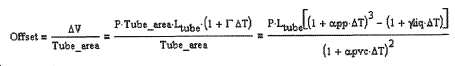
액체들과 고체들이 압축할 수 없는 것으로 간주되므로, 기체들은 이상 기체 법칙을 따라 압축된다.Since liquids and solids are considered incompressible, gases are compressed according to the ideal gas law.
다음과 같은 결론이 이루어진다:The following conclusions are made:
·온도로 인한 디스플레이에서의 오프셋은 부피와 대응하는 채널 직경에 대해 선형적이다;• The offset in the display due to temperature is linear with respect to the volume and the corresponding channel diameter;
·직경이 최대가 되어야 하면서 부피는 최소화되어야 하는데, 이상적으로는 부피가 요구되는 디스플레이 부피와 매칭된다(120㎜ 길이의 채널 및 리딩 컴포트(reading comfort);· The volume should be minimized while the diameter should be maximized, ideally the volume matches the required display volume (120 mm long channel and reading comfort);
·액체/공기(선형 태널) 또는 2중(double) 액체/액체 인터페이스(폐쇄-루프 채널)의 경우에 순응적인(compliant) 챔버가 요구된다;• In the case of liquid/air (linear channels) or double liquid/liquid interfaces (closed-loop channels), a compliant chamber is required;
·저장기의 재료 열적 팽창 계수는 액체의 열적 팽창 계수와 매칭될 수 있다.The material thermal expansion coefficient of the reservoir can be matched to the thermal expansion coefficient of the liquid.
기체에 대한 열적 효과들Thermal effects on gas
액체/기체 인터페이스의 경우 기체들이 디스플레이 챔버 및 감압 챔버에 포함된다. 그것들은 이상기체 법칙을 따른다.For the liquid/gas interface, gases are included in the display chamber and the decompression chamber. They follow the ideal gas law.
P·V = n·R·TP·V = n·R·T
등방성 프로세스(재료 또는 액체 팽창 없음)의 경우, 15℃를 중심으로 25℃ C의 온도 변화를 받는 기체는 설계의 순응 부분과 직접 상호 작용하는 8.7%의 압력 변화를 본다.In the case of an isotropic process (no material or liquid expansion), a gas subjected to a temperature change of 25° C. around 15° C. sees a pressure change of 8.7% that directly interacts with the conforming part of the design.
기체 용해 및 증기 압력Gas dissolution and vapor pressure
튼튼한 압축 챔버를 갖는 액체-기체 디스플레이의 경우, 일부 기체는 디스플레이가 전진할 때 액체에 용해된다. 이 기체는 재설정 후 기체를 배출하는 것이 허용된다. 이 섹션의 목표는 디스플레이에서 기포가 나타날 위험과 디스플레이를 2개로 자를 위험이 존재하는지를 결정하는 것이다.In the case of a liquid-gas display with a sturdy compression chamber, some gases dissolve in the liquid as the display advances. This gas is allowed to vent after reset. The goal of this section is to determine the risk of bubbles appearing on the display and the risk of cutting the display into two.
주어진 양의 액체에서 주어진 압력에서 용해된 기체의 몰수는:The number of moles of gas dissolved at a given pressure in a given amount of liquid is:
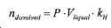
로서 계산된다.Is calculated as
이 등식에서, kH는 액체와 기체에 의존적인 상수이다.In this equation, k H is a liquid and gas dependent constant.
디스플레이가 끝에 있을 때의 압축 챔버에서 도달된 압력은:The pressure reached in the compression chamber at the end of the display is:
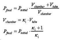
로서 계산된다.Is calculated as
시스템에서 이용 가능한 액체의 총 부피는 저장기 부피와 같다. 저장기 부피 자체는:The total volume of liquid available in the system is equal to the reservoir volume. The reservoir volume itself is:
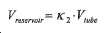
로서 계산될 수 있다.Can be calculated as
그러므로 재설정 후에 탈기될 수 있는 몰수는 다음과 같이 계산될 수 있다:Therefore, the number of moles that can be degassed after resetting can be calculated as follows:

그런 다음 대응하는 부피가 Then the corresponding volume
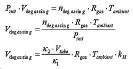
와 같은 수식으로 나타나는 완벽한 기체들의 법칙을 사용하여 계산될 수 있다.It can be calculated using the law of perfect gases represented by the equation
이러한 마지막 표현식은 3개의 파라미터들:This last expression has three parameters:
·튜브의 부피·Tube volume
·튜브와 감압 챔버 부피 사이의 비· Ratio between tube and decompression chamber volume
·튜브와 저장기 부피 사이의 비· Ratio between tube and reservoir volume
에 의존적이라는 것을 볼 수 있다.You can see that it depends on.
디스플레이에 그곳에 남아있게 되는 기포가 나타나는 것을 원하지 않는다면, 탈기 가스의 부피가 튜브 직경과 같거나 더 큰 직경의 구형 기포를 차지해서는 안된다는 기준이 될 수 있다. 이러한 식으로 기포가 튜브보다 작다면, 감압 챔버나 저장기 쪽으로 이동할 가능성이 있고 따라서 디스플레이에서는 볼 수 없다. 그러므로,If you don't want the bubbles to remain there on the display, it can be a criterion that the volume of degassed gas should not occupy spherical bubbles with a diameter equal to or greater than the tube diameter. If the bubble is smaller than the tube in this way, it is likely to move toward the decompression chamber or reservoir and is therefore not visible on the display. therefore,
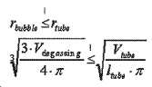
인 것을 원한다.Want to be.
이러한 계산은 입력 파라미터들의 범위에 관해 행해졌고, 물에서의 헬륨의 용해도를 고려한다. 헬륨의 물에서의 용해도는This calculation was done with respect to a range of input parameters, taking into account the solubility of helium in water. The solubility of helium in water
![]()
![]()
이다.to be.
이는 매우 낮은 값(공기:kH= 7.8 · 10-4, 암모니아: kH ![]()
![]()
결론들:Conclusions:
·고려된 가정하에, 튜브의 직경보다 작은 직경의 기체 방출 기포를 갖는 것은 불가능하다.Under the assumptions taken into account, it is impossible to have outgassing bubbles of a diameter smaller than the diameter of the tube.
·기포/튜브 비율들이 2인 것도 매우 큰 튜브들, 큰 챔버 부피들 및 비교적 작은 저장기들로 제한한다.A bubble/tube ratio of 2 also limits very large tubes, large chamber volumes and relatively small reservoirs.
·이들 가정 하에, 기포가 액체 디스플레이를 붕괴시키지 않음을 인정하는 것은 어려운 것으로 보인다.Under these assumptions, it seems difficult to admit that the bubbles do not collapse the liquid display.
·이는 액체-진공 또는 액체-액체 디스플레이가 선호되어야 함을 나타내는 경향이 있다.It tends to indicate that a liquid-vacuum or liquid-liquid display should be preferred.
에너지 예산 계산(energy budget calculation)Energy budget calculation
리튬/망간 및 리튬/카본모노플루오라이드의 시판되는 코인 셀들은 공칭 전압 3V(종점 2V) 및 약 100-600mAh의 배터리 용량을 제공한다. 배터리 셀들 모델들은 CR2025 내지 CR2450 및 BR, 외부 치수는 2.5㎜×Ø20㎜ 내지 5㎜×024.5㎜이다.Commercial coin cells of lithium/manganese and lithium/carbon monofluoride provide a nominal voltage of 3V (end point 2V) and a battery capacity of about 100-600mAh. Battery cell models are CR2025 to CR2450 and BR, and external dimensions are 2.5 mm x Ø20 mm to 5 mm x 024.5 mm.
다음 계산들은 3V(종료 전압 3V) 및 210mAh(가장 최악의 경우 괄호)의 단일 코인 셀을 사용하여 2년 동안 사용 가능한 에너지 예산을 보여준다.The following calculations show the energy budget available for 2 years using a single coin cell of 3V (end voltage 3V) and 210mAh (worst case parentheses).
·5분 스트로크(stroke)들의 양: 210'400(<1s)Amount of 5 minute strokes: 210'400 (<1s)
·12시간 "리턴" 스트로크들의 양: 1461(<30s)Amount of 12 hour "return" strokes: 1461 (<30s)
·조정(adjustment)들의 양(5/개월수): 120(<5s) 주는(Giving):The amount of adjustments (5/months): 120 (<5 s) Giving:
·단계들 수명: 70.675시간들, 최악의 경우Steps life: 70.675 hours, worst case
·기계적 리턴이 있는 단계들 수명(재설정 동안에는 액추에이터가 활성화되지 않음): 58.3시간Steps with mechanical return Life (actuator not activated during reset): 58.3 hours
초기 원형 URS에 관해 선택된 원형 압전 작동된 마이크로모터 스퀴글의 계산:Calculation of selected circular piezoelectrically operated micromotor squiggle with respect to the initial circular URS:
·전력 소모: 330㎽·Power consumption: 330㎽
·주어진 전류 소모: 110㎃· Given current consumption: 110㎃
·스퀴글 총 수명 시간: 210mAh/110㎃ = 1.9시간 또는 예상된 수명 시간의 오직 2.7%Squiggle Total Life Time: 210mAh/110㎃ = 1.9 hours or only 2.7% of expected life time
값들은 에너지 예산이 소비 예산과 동일한 크기의 것이 아님을 보여준다. 스퀴글은 더 낮은 전력 소비로 구동될 수 있지만 10배 더 적은 전력 수명으로도 27 %까지만 연장된다. 데이터 시트는 15gf 축 하중에 관해 1㎜/s 변위를 달성하기 위해 약 150㎽의 최소 구동력을 표시한다.The values show that the energy budget is not the same size as the consumption budget. Squiggle can be driven with lower power consumption, but only extends up to 27% with a 10x less power life. The data sheet displays a minimum driving force of about 150 kPa to achieve a 1 mm/s displacement with respect to a 15 gf axial load.
1개의 배터리 셀에 의해 주어진 규정된 에너지 예산을 가지고, 각 단계에 관해 이론상 이용 가능한 에너지는(최악의 경우):With the prescribed energy budget given by one battery cell, the theoretically available energy for each stage is (worst case):
·코인 셀 에너지:210mAh×3V = 2270JCoin cell energy: 210mAh × 3V = 2270J
·평균 에너지 소비: 10.7mJ·Average energy consumption: 10.7mJ
·평균 전력 소비: 8.9㎽(1s 스트로크들, 30s 재설정 스트로크들, 5s 조정들)Average power consumption: 8.9㎽ (1s strokes, 30s reset strokes, 5s adjustments)
최악의 경우의 조건에 관해서는, 작동 시간의 82% 이상이 클록 기능 5분 단계들(1s 작동)에 있으며 더 짧은 작동 방법으로 크게 줄일 수 있다. 이 계산에서 17%가 선택된 설계(압력이 없는, 순응 챔버)에 따라 또한 크게 감소될 수 있는 나머지 액추에이터 재설정 시간이다. 조정들은 무시 가능하다.As for the worst case condition, more than 82% of the operating time is in the
설계는 추가적인 코인 셀(2배로 하는 용량)용으로 이용 가능한 공간을 고려해야 하고 단계들과 재설정들에 관해 가능한 많이 작동 시간을 감소시켜야 한다. 설계는 또한 기계적인 리로드(reload)를 위한 나선 스프링에서의 기계적인 기초의 에너지 저장을 구현할 수 있고, 그럼에도 불구하고 작동은 스프링 리로드에 맞서 작용해야 한다.The design should take into account the space available for additional coin cells (doubling capacity) and reduce the operating time as much as possible regarding steps and resets. The design can also implement mechanically based energy storage in a spiral spring for mechanical reloading, yet the operation must act against spring reloading.
이 계산에서 포함되지 않는 전기 에너지를 요구하는 다른 기능들은:Other functions that require electrical energy not included in this calculation are:
·마이크로컨트롤러·Microcontroller
·위치 센서(분. 1/5분, 조정들 동안 더 많은)Position sensor (min. 1/5 min, more during adjustments)
·디지털 시계·digital
·백라이트 LED(1/날들, 사용마다 10초, 2.03시간/2년)Backlight LED (1/day, 10 seconds per use, 2.03 hours/2 years)
·버튼 표시기 낮은 소비 청색 LED(하루에 12시간, 8760시간/2년)Low consumption blue LED with button indicator (12 hours a day, 8760 hours/2 years)
이다.to be.
LED 전력 소비:LED power consumption:
시판중인 낮은 소비의 LED들은 2.2V의 공칭 전압과 2.2㎽의 전력을 주는 1㎃의 전류를 필요로 한다.Commercially available low-consumption LEDs require a nominal voltage of 2.2V and a current of 1mA giving a power of 2.2mA.
·버튼 LED는 1388J의 에너지 소비를 가지게 된다(!) ·The button LED has an energy consumption of 1388J (!)
·백라이트 LED들(3V 공칭, 20㎃): 438JBacklight LEDs (3V nominal, 20㎃): 438J
그러므로, LED 버튼 광은 그것이 소비를 감소시키기 위해 지속 시간과 강도에 있어서 재규정되어야 한다. 액추에이터에 관한 에너지 예산은 용량의 20% 미만이 된다.Therefore, the LED button light must be re-defined in duration and intensity in order to reduce consumption. The energy budget for actuators is less than 20% of capacity.
압력 계산들에 관해 설명한다. 액체/기체 인터페이스와 튼튼한 감압 챔버를 갖는 디스플레이의 경우에, 기체가 압축 챔버에서 압축될 때 액체가 전진하는 동안 압력은 선형으로 증가한다. 최종 압력은 2개의 파라미터, 즉Describe pressure calculations. In the case of a display with a liquid/gas interface and a robust decompression chamber, the pressure increases linearly as the liquid advances as the gas is compressed in the compression chamber. The final pressure is 2 parameters
·압축되어야 하는 기체의 양을 규정하는 튜브의 섹션A section of the tube that defines the amount of gas to be compressed
·감압 챔버의 부피·Volume of decompression chamber
에 의존하게 된다.Depend on it.
그러므로 최종 압력은Therefore, the final pressure
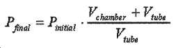
로서 계산될 수 있다.Can be calculated as
이들 파라미터들의 함수로서 압축 챔버에서의 최종 압력은 도 57에 나타나 있다. 동일한 값들이 도 58에서는 윤곽선 그림(contour plot)으로서 나타나 있다.The final pressure in the compression chamber as a function of these parameters is shown in Figure 57. The same values are shown in FIG. 58 as a contour plot.
이들 도면에서 보일 수 있는 것처럼, 큰 압력들이 쉽게 도달될 수 있다. 이는 모두 액추에이터에서 더 높은 에너지 소비와 표시기에 관한 더 높은 기계적 요구 조건을 초래하게 된다. 이들 강제 사항들을 제한하기 위해 취해질 수 있는 조치는 다음과 같다. 감압 챔버 부피는 최대화될 수 있고, 이는 전체적인 사이즈의 증가를 수반한다. 또한, 튜브 섹션이 최소화될 수 있지만, 이는 가시도(visibility)에 영향을 미친다. 또, 액체-액체 인터페이스가 사용될 수 있는데, 이는 튜브의 각 단부에 하나의 순응 저장기를 요구하거나, 대안으로서 루프를 만드는 튜브로서, 어떤 종류의 저장기 공간도 요구하지 않을 것이다.As can be seen in these figures, large pressures can be easily reached. This results in higher energy consumption in the actuator and higher mechanical requirements for the indicator. Actions that can be taken to limit these mandates include: The reduced pressure chamber volume can be maximized, which entails an increase in overall size. Also, the tube section can be minimized, but this affects the visibility. Also, a liquid-liquid interface could be used, which would require one compliant reservoir at each end of the tube, or alternatively, as a tube making a loop, would not require any kind of reservoir space.
튼튼한 감압 챔버 힘 계산들, 즉 피스톤 반응력을 가진 피스톤을 설명한다. 피스톤과 액체/기체 인터페이스가 있는 시스템에 관해서는, 그러한 피스톤에 작용하는 힘이 표시기에서의 액체의 전진에 따라 선형적으로 변하게 될 것이다. 이는 차례로 피스톤의 단면에 의존하는 힘으로 전환될 것이고, 이러한 힘은:Explain the robust decompression chamber force calculations, ie pistons with piston reaction forces. For systems with a piston/liquid/gas interface, the force acting on such a piston will change linearly as the liquid advances in the indicator. This in turn will translate into a force dependent on the cross section of the piston, which will:

로 쓰여질 수 있다. 튜브 직경, 챔버 부피 및 피스톤 직경의 함수로서, 피스톤에 작용하는 최대 힘은 도 59에 나타나 있다.Can be written as The maximum force acting on the piston as a function of tube diameter, chamber volume and piston diameter is shown in FIG. 59.
그래프의 많은 부분에서 최대 힘이 1[N]을 초과하지 않는 것으로 보일 수 있다.In many parts of the graph, it can be seen that the maximum force does not exceed 1 [N].
피스톤 직경과 튜브 직경의 함수로서 피스톤 스트로크(stroke)는 도 60에 제시된다. 그것은 장치의 치수 강제 사항들에 의존하여 설정되어야 할 것이지만, 펌프 에너지 소비에도 영향을 미칠 것이고, 더 큰 피스톤에 관해서는 더 많은 힘이 작용될 것을 요구할 것이다.The piston stroke as a function of piston diameter and tube diameter is shown in FIG. 60. It will have to be set depending on the dimensional constraints of the device, but it will also affect pump energy consumption and will require more force to act on the larger piston.
기계적인 파워는 Mechanical power
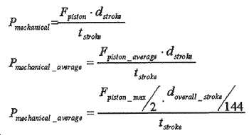
로서 규정된다.Is defined as.
dstroke는 5분 증가량마다 피스톤에 의해 제공되어야 하는 거리를 나타내고, 이전에 계산된 피스톤의 전체 스트로크 길이를 doverall_stroke라고 하며 tstroke는 1[s]로 규정된 스트로크 지속 시간을 나타낸다. 액추에이터 힘이 디스플레이가 전진함에 따라 선형적으로 상승하기 때문에, 최대 계산된 힘의 절반이 평균 요구된 힘인 것으로 간주된다.d stroke represents the distance to be provided by the piston in increments of 5 minutes, the total stroke length of the previously calculated piston is called d overall_stroke , and t stroke represents the stroke duration specified by 1[s]. Since the actuator force rises linearly as the display advances, half of the maximum calculated force is considered to be the average required force.
그런 다음 요구된 전력은Then the required power

로서 계산될 수 있다.Can be calculated as
여기서 ηtotal는 전기 및 기계적 파워 손실을 모두 고려하여 시스템의 전체 효율을 나타낸다. 그런 다음 도 61에 제시된 것과 같이 전력 소비의 등위 표면들이 그려질 수 있다. 전체적인 허용 가능한 전력 소비는, 하나의 코인 셀이 2년 동안의 연속적으로 작동하는 동안에 시스템에 공급할 수 있는 것과 같은 11[㎽]인 것으로 추정된다.Here, η total represents the overall efficiency of the system, taking into account both electrical and mechanical power losses. The isosurfaces of power consumption can then be drawn as shown in FIG. 61. It is estimated that the overall allowable power consumption is 11 [㎽], such that one coin cell can supply the system during two years of continuous operation.
평균 에너지 소비에 대한 합리적인 한계를 설정하기 위해 전체 효율을 30 % 미만으로 고려하면 3[mW]의 값에 도달한다.To set a reasonable limit to the average energy consumption, considering the overall efficiency of less than 30%, a value of 3 [mW] is reached.
최대 허용 가능한 전력 소비의 계산을 위해, 전진 운동 중에 생성된 압력을 사용하여 리턴이 행해진다고 가정하는데, 즉 액추에이터가 리턴을 위해 활성화될 필요는 없다고 가정한다.For calculation of the maximum allowable power consumption, it is assumed that the return is done using the pressure generated during the forward motion, i.e. the actuator need not be activated for return.
전력 소비에 관한 경향은 힘의 경향과 동일하지 않은 것으로 보일 수 있다. 이는 피스톤이 클수록 더 많은 힘이 필요하지만 그것들의 스트로크 거리가 크게 줄어들기 때문이다.The trend towards power consumption may not seem to be the same as the trend for power. This is because larger pistons require more force, but their stroke distance is significantly reduced.
피스톤 리턴 시간 대 리턴 힘을 설명한다. 도 62에는 액체-진공 시스템의 개략적인 표현이 제시된다. 이 시스템에서는, 시스템이 평형 상태에 있도록 진공에 의해 발휘된 힘이 리턴 스프링의 힘에 의해 보상되어야 한다. 게다가, 리턴이 충분히 신속하게 행해지도록 힘이 추가되어야 한다.Describe the piston return time versus return force. 62 shows a schematic representation of a liquid-vacuum system. In this system, the force exerted by the vacuum must be compensated by the force of the return spring so that the system is in equilibrium. In addition, force must be added so that the return is done quickly enough.
전체적인 힘들을 낮추는, 진공에 의해 생성된 흡입이 존재하지 않는다는 점을 제외하고는, 순응 압축 챔버와의 액체-기체 인터페이스 또는 액체-액체 시스템에서의 상황은 동일하다는 점을 주목하라.Note that the situation in the liquid-gas interface or liquid-liquid system with the adaptive compression chamber is the same, except that there is no vacuum generated suction, which lowers the overall force.
특정 압력 차이(pressure differential) 하에서, 그리고 흐름이 얇은 판자 모양이라는 점을 가정하면, 튜브에서의 흐름은 다음과 같이 계산된다:Under a certain pressure differential, and assuming that the flow is thin, the flow in the tube is calculated as follows:
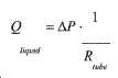
여기서 Rtube는 액체의 전진에 대한 튜브의 유체 저항이다. 그것은 포아즈이유 법칙(Poiseuille's law)에 의해 다음과 같이 계산될 수 있다:Where R tube is the fluid resistance of the tube to the advancement of the liquid. It can be calculated by Poisuille's law as follows:
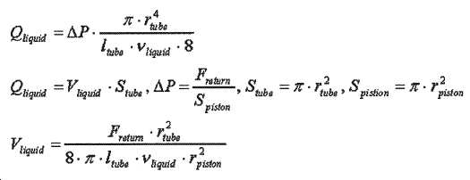
완전히 채워진 디스플레이로부터, 액체의 완전한 리턴을 고려하면 액체의 진행에 따라 유체 저항이 꾸준히 떨어질 것이다. 평균 유체 저항은 튜브의 전체 길이의 절반의 유체 저항과 같게 될 것이다. 하지만, 인터페이스가 액체-액체 인터페이스이라면, 유체 저항은 액체가 진행함에 따라 변경되지 않을 것이다. 그러므로 후속하는 속도(speed)들은 양쪽 경우들 모두에 관해 다음과 같이 계산된다:From a fully filled display, considering the complete return of the liquid, the fluid resistance will drop steadily as the liquid progresses. The average fluid resistance will be equal to the fluid resistance of half the overall length of the tube. However, if the interface is a liquid-liquid interface, the fluid resistance will not change as the liquid progresses. Therefore, the following speeds are calculated as follows for both cases:

그러므로 액체의 리턴 속도는 4개의 파라미터들, 즉Therefore, the return speed of the liquid is four parameters,
·복쉬 스프링 힘·Bush spring force
·튜브 반경·Tube radius
·액체의 점도·Liquid viscosity
·피스톤 반경·Piston radius
에 의존한다.Depends on
리턴을 위한 최대 특정된 시간은 30[s]이다.The maximum specified time for return is 30[s].
도 63에서는 실리콘-실리콘 인터페이스에 관해서 튜브 반경, 피스톤 반경, 및 리턴 힘의 함수로서 리턴 시간들의 등위면들이 제시되고, 도 64에서는 물-물 인터페이스에 관해서 튜브 반경, 피스톤 반경, 및 리턴 힘의 함수로서 리턴 시간들의 등위면들이 제시된다. 양쪽 경우 모두에서, 리턴에 30초 이상이 걸리는 상황이 이례적이라는 점을 볼 수 있다. 하지만, 훨씬 더 신속한 리턴이 요구된다면, 치수들의 선택시 특별한 주의가 기울여져야 한다.In FIG. 63 isometric surfaces of return times as a function of tube radius, piston radius, and return force for the silicon-silicon interface, and in FIG. 64 function of tube radius, piston radius, and return force for the water-water interface. As isometric surfaces of the return times are presented. In both cases, it can be seen that the situation where the return takes more than 30 seconds is unusual. However, if a much faster return is required, special care must be taken when selecting dimensions.
나선 휠 토크 계산들과 일반적인 나선 공식에 대한 설명이 이루어진다. 도 65에는 임의의 주어진 시간에서의 나선에 작용하는 힘들이 제시된다. 존재하는 변수들은 피스톤의 힘(F), 나선에서 토크를 발생시키는 등가 수직력(R), 접선과 나선 사이의 각도(a) 및 이 점을 지나는 원의 접선(계산이 이어짐), 마찰로 인한 ρ= α tan(μ)로 계산된 추가 각도(ρ)(여기서 μ는 마찰), 및 나선 휠을 돌리는 데 필요한 토크(M)가 있다.A description of the helix wheel torque calculations and general helix formula is made. Figure 65 shows the forces acting on the helix at any given time. Existing variables are the force (F) of the piston, the equivalent vertical force (R) that generates torque in the helix, the angle (a) between the tangent and the helix, and the tangent of the circle passing through this point (calculation continues), ρ due to friction = an additional angle ρ calculated as α tan(μ) (where μ is friction), and torque (M) required to turn the spiral wheel.
α는 임의의 점에서 다음과 같이 계산된다:α is calculated as follows at any point:
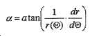
그러므로 요구되는 토크는 다음과 같이 쓰여진다:Therefore, the required torque is written as:
![]()
![]()
일정한 토크 나선 계산에 대해 설명한다. 만약 튼튼한 압축 챔버가 사용되어야 한다면, 드라이브 상의 토크를 일정하게 유지하기 위해 나선 모양이 그에 따라 맞추어져야 한다. 이 경우에 대수 나선(logarithmic spiral)이 사용된 경우, 디스플레이가 진행되는 동안 토크가 증가하게 되는데, 이는 스트로크의 끝에서 충분한 토크를 제공할 수 있도록 하기 위해 대부분의 스트로크 거리에 대해 과도하게 치수가 정해지는 드라이브를 구현하는 것을 요구하게 된다.Describe the constant torque spiral calculation. If a sturdy compression chamber should be used, the helix shape must be adjusted accordingly to maintain a constant torque on the drive. In this case, if a logarithmic spiral is used, the torque increases during the display, which is oversized for most stroke distances to provide sufficient torque at the end of the stroke. Losing the drive will require implementation.
일반화된 나선 시스템이 그것의 중요한(key) 값들 중 일부와 함께 도 66에 제시된다.A generalized spiral system is presented in FIG. 66 with some of its key values.
압축 챔버에서의 압력은 다음과 같이 쓰여질 수 있다:The pressure in the compression chamber can be written as:

우리는 이 계산에서 드라이브 상에서 일정한 토크를 가지기를 원한다. 이전 섹션에서 보여지듯이, 이러한 토크는 다음과 같이 계산된다:We want to have a constant torque on the drive in this calculation. As shown in the previous section, this torque is calculated as follows:
![]()
![]()
이 등식을 풀기 위해서는, 마찰의 기여도가 0이라고 가정한다. 우리는 나선의 각도인 α가 다음과 같이 계산될 수 있다는 사실을 안다:To solve this equation, it is assumed that the contribution of friction is zero. We know that the angle α of the helix can be calculated as:

그러므로 토크는 대략 다음과 같이 계산될 수 있다:Therefore, the torque can be roughly calculated as:

일정한 토크란 나선의 각도 위치의 함수로서 토크의 미분이 0이 되길 원한다는 것을 의미한다. 그러므로:Constant torque means that you want the differential of the torque to be zero as a function of the angular position of the helix. therefore:

이다.to be.
힘이 각도에 의존적이기 때문에, 이는 복잡한 2차 미분 방정식을 초래한다. 나선 휠을 수반하는 솔루션과 액체 가스 인터페이스를 선택하면 나선의 모양이 수치로 계산된다.Since the force is angle dependent, this results in a complex quadratic differential equation. When you select a solution with a spiral wheel and a liquid gas interface, the shape of the spiral is calculated numerically.
아르키메데스 나선 이외의 나선 형태를 사용하는 경우, 나선의 거리 증분은 각도에 따라 일정하지 않을 것이기 때문에 모터에 의해 수행되는 스텝 크기는 피스톤의 움직임에 따라 일정하지 않을 것이다는 점을 주목하라.Note that when using a helix type other than Archimedes helix, the step size performed by the motor will not be constant with the movement of the piston because the distance increment of the helix will not be constant with angle.
아르키메데스 나선 계산들에 대해 설명한다. 아르키메데스 나선은 가장 간단한 모양들 중 하나이고, 그 방정식은 다음과 같다:Describe the Archimedean Spiral Calculations. The Archimedean Spiral is one of the simplest shapes, and the equation is:

도 67에는 그러한 한 개의 나선이 제시된다. 그것은 주어진 나선의 회전에 대해, 피스톤에 대해 눌려진 피스톤의 선형 변위는 각도에 관계없이 항상 일정하다는 특별함을 가진다. 이러한 상황은 다른 나선 모양들에 대해서도 사실인 것은 아니다. 아르키메데스 나선 이외의 다른 나선을 사용하는 경우, 표시기의 일정한 변위를 달성하기 위해, 모터의 회전 속도는 일정하지 않게 된다.Fig. 67 shows one such spiral. It has the special feature that for a given spiral rotation, the linear displacement of the piston pressed against the piston is always constant regardless of the angle. This situation is not true for other spiral shapes. When a spiral other than the Archimedes spiral is used, the rotational speed of the motor is not constant in order to achieve a constant displacement of the indicator.
아르키메데스 나선은 각도 위치(Θ)의 진행에 따라 나선 경사도(α)가 감소하고, 그 결과 필요한 토크가 감소하는 특성을 갖는다. 그것은 이후, 기체가 튼튼한 챔버에서 압축되어야 하는 상황들에 대한 가능한 해결책으로서 제시된다.Archimedes spirals have the characteristic that the spiral inclination α decreases as the angular position Θ progresses, and as a result, the required torque decreases. It is then presented as a possible solution to situations where the gas must be compressed in a sturdy chamber.
앞선 챔버에서 계산된 것처럼, 일반적인 나선 압축 기체에 관해 액추에이터에 의해 제공되어야 할 토크는 다음과 같다:As calculated in the previous chamber, the torque to be provided by the actuator with respect to the common spiral compressed gas is:
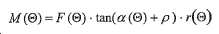
아르키메데스 나선에서, 나선 경사 각도는 다음과 같이 계산된다:In Archimedes spirals, the angle of the spiral inclination is calculated as follows:
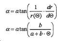
토크는 다음과 같다:The torque is:
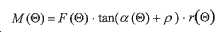
마찰의 효과를 무시하면 다음과 같이 쓰는 것이 가능하다:Ignoring the effect of friction, it is possible to write:

여기서 액체-기체 인터페이스에 관한 토크 계산을 설명하고, 이 경우 힘 계산들은 일정한 코트 나선 계산을 기술하는 위 섹션에서 확립된 것이다. 다음과 같이 쓸 수 있다:Here we describe the torque calculation for the liquid-gas interface, in which case the force calculations were established in the above section describing constant coat helix calculation. You can write:
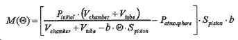
우리의 특정한 경우에, 나선은 오직 한 번만 회전한다. 그러므로 나선의 파라미터들은 나선의 최소 반지름인 a로서 규정되며, 이는 설계의 중요성만을 가진다.In our particular case, the spiral rotates only once. Therefore, the parameters of the helix are defined as the minimum radius of the helix a, which has only the importance of design.
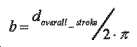
그러므로,therefore,

이다.to be.
아르키메데스 나선의 경우 마찰이 무시되는 경우 토크 특성은 나선의 기하학적 형태에 의존하지 않는다는 사실을 주목할 수 있다. 이는 다음과 같이 설명될 수 있는데, 즉 만약 나선이 높은 경사도를 가진다면, 피스톤의 스트로크가 더 길어질 것이고, 이는 그것의 표면이 더 낮게 된다는 것을 의미한다. 이로 인해 피스톤 표면에 더 낮은 압력이 가해져 높은 경사도를 보상한다.It can be noted that in the case of Archimedes helix, the torque characteristic does not depend on the geometry of the helix when friction is neglected. This can be explained as follows, if the helix has a high slope, the stroke of the piston will be longer, which means that its surface will be lower. This results in lower pressure applied to the piston surface, compensating for higher slopes.
저장기의 부피는 튜브의 부피와 동일하기 때문에 계산에 아무런 영향을 미치지 않는다는 점을 주목하라. 저장기는 단지 튜브 치수들에 따라 크기 조정되어야 할 것이다.Note that the volume of the reservoir is the same as that of the tube, so it has no effect on the calculation. The reservoir will only have to be sized according to the tube dimensions.
다음과 같이, 마지막 방정식은 튜브 부피의 함수로서 챔버 부피를 제공함으로써 간략화될 수 있다:The final equation can be simplified by providing the chamber volume as a function of tube volume, as follows:

토크는 여전히 튜브 직경의 절대 값에 따라 달라진다는 것이 주목할 가치가 있다. 하지만, 각도 위치에 따른 토크 변화와 관련하여 비율만 중요하다. 도 68은 2[㎜] 튜브 직경에 관해서, 튜브 부피 비와 각 위치에 대한 챔버 부피의 함수로서의 토크의 곡선을 나타낸다.It is worth noting that the torque still depends on the absolute value of the tube diameter. However, only the ratio is important in relation to the torque change depending on the angular position. Figure 68 shows the curve of torque as a function of tube volume ratio and chamber volume for each position, for 2 [mm] tube diameter.
동일한 곡선이 도 69에서 상이한 비율들에 대한 컷(cut)들로서 표현된다. 챔버 체적에 관해 2보다 큰 비율들이 사용되는 경우 토크가 상대적으로 안정적으로 유지될 수 있음을 볼 수 있다.The same curve is represented in FIG. 69 as cuts for different ratios. It can be seen that the torque can be kept relatively stable when ratios greater than 2 with respect to the chamber volume are used.
보이는 바와 같이, 이러한 대략적인 계산들은 마찰을 무시하고, 이는 휠의 회전 시작시 널(null) 토크로 이어진다. 물론 정확한 결과를 위해서는 마찰력을 고려해야 한다.As can be seen, these approximate calculations ignore friction, which leads to a null torque at the start of the wheel's rotation. Of course, frictional forces must be considered for accurate results.
우리는 아르키메데스 나선을 사용하는 것이 모터 제어를 단순화시킨다고 결론을 내리는데, 이는 각각의 모터 위치 증분이 일정한 액체 레벨 증분에 대응하기 때문이다. 하지만, 이러한 나선 기하학적 형태는 그것의 각 위치에 따라 가변적인 토크를 요구하게 된다. 압축 챔버가 튜브 부피가 두 배 이상인 경우에만 아르키메데스 나선으로 토크를 안정적으로 유지하는 것이 가능하다. 장치가 더 소형인 경우 일정한 토크 타선이 사용되어야 한다. 대안적으로, 액체-액체 또는 액체-진공 인터페이스를 사용하면 이 문제를 회피할 수 있다.We conclude that the use of Archimedes spirals simplifies motor control, because each motor position increment corresponds to a constant liquid level increment. However, this spiral geometry requires variable torque depending on its angular position. It is possible to keep the torque stable with the Archimedean Spiral only if the compression chamber is at least twice the volume of the tube. If the device is smaller, a constant torque break should be used. Alternatively, this problem can be avoided by using a liquid-liquid or liquid-vacuum interface.
이제 액체-액체 인터페이스에 관한 토크 계산을 기술한다. 액체-액체 또는 액체-진공 인터페이스의 경우, 피스톤에 작용하는 힘은 일정한 것으로 간주된다. 그 토크는 이 경우 다음과 같이 계산될 수 있다:Now the torque calculation for the liquid-liquid interface is described. In the case of a liquid-liquid or liquid-vacuum interface, the force acting on the piston is considered constant. The torque can be calculated in this case as follows:
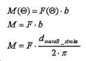
토크가 일정하고 나선의 전체 스트로크에만 의존한다는 것을 알 수 있다. 힘은 5.8에서 확립된 계산들로 저장기에서 액체가 충분히 빠르게 리턴하는 것을 보장하는 최소 힘으로 결정될 것이다. 쓰여진 바와 같이, 리턴 스프링 힘은 원하는 리턴 시간의 함수로서 다음과 같이 계산될 수 있다:It can be seen that the torque is constant and depends only on the entire stroke of the helix. The force will be determined as the minimum force that ensures that the liquid returns quickly enough from the reservoir with calculations established in 5.8. As written, the return spring force can be calculated as a function of the desired return time as follows:
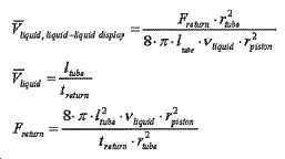
그러므로 토크는 다음과 같이 계산될 수 있다:Therefore, the torque can be calculated as:

이는 실제로 주목할 만한 결과이다. 이 상황에서 요구된 토크는 고려된 유체의 점도와 원하는 리턴 시간에만 의존하고, 튜브 길이는 주어진다.This is actually a notable result. The torque required in this situation only depends on the viscosity of the fluid considered and the desired return time, and the tube length is given.
액체-진공 인터페이스에 관해서는, 그러한 경우에 액체의 리턴 동안 튜브의 평균 유체 저항과 같이 이러한 토크는 2로 나누어 질 것이다.As for the liquid-vacuum interface, in this case this torque will be divided by 2, such as the average fluid resistance of the tube during the return of the liquid.
요구되는 토크가 액체의 점도에 직접적으로 의존한다는 것을 볼 수 있다. 도 70에는 물과 실리콘 오일에 관한 결과로서 요구되는 토크가 나타나 있다. 물과 실리콘 오닐 사이의 점도의 차이로 인해, 토크 요구 조건을 궁극적으로 상당히 상이한 것을 볼 수 있다. 하지만, 2가지 경우 모두 토크들은 합리적인 한계들 내에서 유지된다.It can be seen that the required torque directly depends on the viscosity of the liquid. Figure 70 shows the torque required as a result of water and silicone oil. It can be seen that due to the difference in viscosity between water and silicone onyl, the torque requirements are ultimately quite different. However, in both cases, the torques remain within reasonable limits.
마찰이 무시되는 첫 번째 근사(approximation)에서, 토크들은 일반적으로 액체-가스 인터페이스보다 액체-액체 또는 액체-진공 인터페이스에 비해 열등한 크기의 것들이라는 것이 주목할 만하다.It is noteworthy that in the first approximation where friction is neglected, the torques are generally of inferior size compared to the liquid-liquid or liquid-vacuum interface rather than the liquid-gas interface.
이제 전기습윤 및 파워 소비에 관해 설명한다. 전기습윤 원리의 개략적인 것이 도 71에 나타나 있다. 도면의 우측에 나타낸 바와 같이, 전기습윤 디스플레이는 커패시터들의 배열로서 나타내어질 수 있다. 액적이 변위되어야 할 때, 그것 다음에 있는 전극에 전류가 공급되고, 이는 이 스폿(spot)에서의 표면 장력을 줄여서 액적을 끌어당긴다. 전류가 공급된 전극은 절연 및 소수화에 의해 발생된 커패시터에 연결되고, 그것의 접지 전극은 물 액적 자체이다.Now we will discuss electrowetting and power consumption. The schematic of the electrowetting principle is shown in FIG. 71. As shown on the right side of the figure, the electrowetting display can be represented as an array of capacitors. When the droplet needs to be displaced, an electric current is supplied to the electrode next to it, which reduces the surface tension at this spot and attracts the droplet. The energized electrode is connected to a capacitor generated by insulation and hydrophobization, and its ground electrode is the water droplet itself.
평면 커패시터의 값은 다음과 같이 계산될 수 있다:The value of a planar capacitor can be calculated as follows:

우리의 경우, 전극들을 직사각형 모양을 가지고, 커패시터는 2개의 연속 층들(절연 및 소수화)로 이루어진다. 하지만 소수화 층은 전기적 절연을 제공하기에는 너무 얇다. 절연층의 특성들은 다음과 같다:In our case, the electrodes have a rectangular shape, and the capacitor consists of two consecutive layers (insulation and hydrophobicization). However, the hydrophobic layer is too thin to provide electrical insulation. The properties of the insulating layer are as follows:
전극들의 사이즈는 다음과 같이 결정될 수 있다:The size of the electrodes can be determined as follows:
·길이 = 0.833[㎜]→144 전극들에서 나누어진 120[㎜]·Length = 0.833 [mm] → 120 [mm] divided by 144 electrodes
·폭 = 1[㎜], 가정(assumption)·Width = 1[㎜], assumption
그런 다음 커패시터 값은 C = 29[㎊]에서 대략적으로 계산된다. 이 값은 문헌의 전형적인 값에 해당하며 일반적인 용량성 감지 칩들에 의해 쉽게 측정할 수 있는 값이다.Then, the capacitor value is roughly calculated at C = 29[㎊]. This value corresponds to a typical value in the literature and can be easily measured by typical capacitive sensing chips.
그런 다음 커패시터가 프로세스에서 완전히 충전된다고 가정하는 하나의 스텝 증분에 관한 전력 소비의 제1 가정은 다음과 같이 행해질 수 있다:Then the first assumption of power consumption in one step increment assuming that the capacitor is fully charged in the process can be made as follows:

목표는 최소 가능한 전압으로 변위를 행하는 것이다. 도 72에 나타낸 결과들을 고려한다면, 3[㎐]에서 20[V] 전압으로 액적을 움직이는 것이 가능하게 보인다. 그러므로 변위 시간은 0.3[s]이고, 요구된 전력은 0.038[㎼]이다.The goal is to perform displacement with the minimum possible voltage. Considering the results shown in FIG. 72, it seems possible to move the droplets from 3 [㎐] to 20 [V] voltage. Therefore, the displacement time is 0.3[s] and the required power is 0.038[㎼].
우리는 이전에 계산된 파워의 값이 정도의 크기(order of magnitude)의 표시기로서 간주되어야 한다는 결론을 내린다. 이 값을 확인하려면 정제된(refined) 계산들 및 테스트들이 행해져야 한다. 이러한 정도의 크기는 문헌에서 확인된다. 이러한 소비에는 전자 제품의 소비가 추가되어야 한다.We conclude that the previously calculated value of power should be considered as an indicator of order of magnitude. To confirm this value, refined calculations and tests have to be done. The magnitude of this degree is confirmed in the literature. The consumption of electronic products must be added to the consumption.
이제 표현(representation) 및 순위(ranking)의 실시예를 기술한다. 형태(morphological) 상자들 방법은 완전한 개념들을 생성하기 위해, 장치의 다른 기능들에 대해 제시된 솔루션들을 결합하는 것을 목표로 한다. 전체 조합(global combination)뿐만 아니라 보유된 솔루션들의 요약이 도 73에 제시되어 있다. 보일 수 있는 것처럼, 이러한 기능은 장치의 핵심(core)에 있기 때문에 작동 방법마다 하나의 개념이 설계되었다. 그러므로 5개의 상이한 개념들이 이후 제시된다. 액체 기둥 감지가 선택된 작동 방법에 매우 의존적이면서, 인터페이스에 관해서는 그러하지 않다는 것을 주목하라. 제안된 인터페이스는 여전히 제안된 개념들 중 일부를 위해 변경될 수 있다. 도 74에는 5개의 상이한 개념들이 제시된다. 이 섹션은 뒤쪽 섹션에서 제시된 2개의 솔루션들의 예비 설계들을 제시한다. '가정들(Assumptions)'이라는 부분은 실제적인 이유들 때문에 또는 계산을 단순화하기 위해 가정되는 파라미터들을 제시한다. "예비 설계 선택들" 부분은 다른 파라미터들로 이끄는 계산들을 제시한다.An embodiment of representation and ranking is now described. The morphological boxes method aims to combine solutions presented for different functions of the device, to create complete concepts. A summary of the solutions retained as well as the global combination is presented in FIG. 73. As can be seen, since this function is at the core of the device, one concept was designed for each method of operation. Therefore, five different concepts are presented later. Note that liquid column sensing is highly dependent on the chosen method of operation, but not on the interface. The proposed interface can still be modified for some of the proposed concepts. 74, five different concepts are presented. This section presents preliminary designs of the two solutions presented in the later section. The section'Assumptions' presents the parameters assumed for practical reasons or to simplify the calculation. The “Preliminary Design Options” section presents calculations leading to different parameters.
실시예 1 - 나선 캠을 설명한다. 이 단계에서는 어떠한 충분한 최적화도 행해지지 않을 것이고, 일부 파라미터들이 가정될 것이다. 그것들은 도 75에 제시된다.Example 1-A spiral cam will be described. No sufficient optimization will be done at this stage, and some parameters will be assumed. They are presented in Figure 75.
여기서는 쉐프 무브먼트들을 기술한다. 발명자의 이름을 딴 "Lavet" 모터와 같은 스테퍼 모터들이 시계제작자 업계에서 널리 사용된다. 몇몇 규격품 시계 무브먼트들이 후속하는 주된 특징들을 가지고 시장에서 입수 가능하다.Here, the chef movements are described. Stepper motors, such as the "Lavet" motor, named after the inventor, are widely used in the watchmaker industry. Several off-the-shelf watch movements are available in the market with the main features that follow.
토크: 기어 트레인 감소 후 시간 휠 상에서 최대 1 내지 3mNm까지 제2 샤프트 상에서 5 내지 18μNm;Torque: 5 to 18 μNm on the second shaft up to 1 to 3 mNm on the time wheel after reduction of the gear train;
공칭 전압: 1.5V;Nominal voltage: 1.5V;
전형적인 소비:2㎂(부하가 없음);Typical consumption: 2 kPa (no load);
산화은 배터리로 설계된 ~ 28mAh, 예상된 수명;<2년;Designed with silver oxide battery ~ 28mAh, expected lifespan; <2 years;
미오(Mio) 부품들/년당 가격: 0.45(플라스틱) 내지 2.25USD(금속).Mio Parts/Price per year: 0.45 (plastic) to 2.25 USD (metal).
무브먼트들은 가변 길이들의 디스플레이 튜브들을 어드레스할 수 없다. 예들은 도 77에 도시된다.Movements cannot address display tubes of varying lengths. Examples are shown in FIG. 77.
저비용 플라스틱과 금속제 시계 무브먼트는 보통 초 바퀴(seconds wheel), 분 바퀴(minute wheel)(선택적인) 및 시 바퀴(hour wheel)를 어드레스하는 기어 트레인을 가진다. 설계는 때때로 모터를 회전시키지 않고 설정 굴대(setting stem)의 도움으로 시간(시 및 분)을 조정하는 것을 허용하는 마찰 클러치를 포함한다.Low-cost plastic and metal watch movements usually have a gear train addressing the seconds wheel, the minute wheel (optional) and the hour wheel. The design sometimes includes a friction clutch that allows adjusting the hours (hours and minutes) with the help of a setting stem without rotating the motor.
시계 무브먼트의 설계는 도 78a에서 디지털 석영 시계에 관해 예시된 것과 같고 도 78b에서 기계적인 시계에 관해 예시된 것과 같다.The design of the watch movement is the same as that illustrated with respect to the digital quartz watch in FIG. 78A and the one illustrated with respect to the mechanical watch in FIG. 78B.
저비용 플라스틱과 금속제 시계 무브먼트는 보통 초 바퀴, 분 바퀴(선택적인) 및 시 바퀴를 어드레스하는 기어 트레인을 가진다. 설계는 때때로 모터를 회전시키지 않고 설정 굴대의 도움으로 시간(시 및 분)을 조정하는 것을 허용하는 마찰 클러치를 포함한다.Low-cost plastic and metal watch movements usually have a gear train addressing the seconds wheel, the minutes wheel (optional), and the hours wheel. The design sometimes includes a friction clutch that allows adjusting the hours (hours and minutes) with the help of a set axle without rotating the motor.
시 바퀴는 관심 대상인데 이는 그것이 무브먼트 조립체의 상부에 있고 장치에 관한 나선 캠에 직접 연결될 수 있기 때문이다. 무브먼트들은 이미 24시간/하루의 차원을 가지고 실지 설명자 설계용으로 쉽게 될 수 있다.The sea wheel is of interest because it is on the top of the movement assembly and can be connected directly to the spiral cam on the device. Movements already have a dimension of 24 hours/day and can be easily used for field descriptor design.
여기서 OEM 시계 무브먼트를 갖는 시간 조정들을 기술한다. 시판중인 시계에 관해, 스테퍼 모터는 계속해서 24시간 사이클들에 관해 초당 6°, 분당 6°및 시간당 15°의 분 분해능(minute resolution)을 주는 시간을 증가시킨다. 조정들의 경우에 시간은 12시간 시간 분해능에서 시 및 분 기어 트레인에 작용함으로써 새로운 시간에 대해 비교적 적응된다. 그런 다음 스테퍼 모터는 새로운 상대적 시간 표시를 가지고 시간을 증가시킬 것이다.Here, the time adjustments with the OEM watch movement are described. For commercial watches, the stepper motor continues to increase the time giving minute resolution of 6° per second, 6° per minute and 15° per hour for 24 hour cycles. In the case of adjustments, time is relatively adapted to the new time by acting on the hour and minute gear trains at 12 hour time resolution. The stepper motor will then increase the time with a new relative time indication.
아날로그 액체 시계 실시예에 관해서는 다음의 고려 사항들이 유의되어야 한다.The following considerations should be noted with respect to the analog liquid clock embodiment.
시간은 24시간 시간 범위에서 상대적으로 조정 가능하다(디스플레이에 관해서는 12시간, 버튼 LED 표시기에 관해서는 24시간).The time is relatively adjustable in the 24-hour time range (12 hours for the display and 24 hours for the button LED indicator).
시간 증분은 개방 루프에 있지 않은데, 이는 12시간 마다 재설정이 일어나고 오전 6시 또는 오후 6시 값과 매칭되어야 하기 때문이다. 이 점에 있어서는, 액체 디스플레이와 상대적인 시간 바퀴에 대한 결합이 완벽하게 매칭되어야 한다(개방 루프 시간 디스플레이).The time increment is not in the open loop, because a reset occurs every 12 hours and must match the value at 6 AM or 6 PM. In this regard, the combination of the liquid display and the relative time wheel should be a perfect match (open loop time display).
액체 디스플레이는 피스톤 사이즈와 저장기가 장치 조립 동안에 적합하게 되지 않는 한 가변 채널 길이에 따라 일정한 기준으로 정해질 수 없다.The liquid display cannot be set on a constant basis with variable channel lengths unless the piston size and reservoir are adapted during device assembly.
완전히 기게적인 시계 무브먼트(ETA, lamania 등) 통합의 경우에 확인되어야 할 에너지 예산에 대한 고려 사항들은 동일하다. 예비 설계는 저비용 플라스틱 시계 무브먼트에 초점을 맞춘다.In the case of a fully mechanical watch movement (ETA, lamania, etc.) integration, the energy budget considerations to be confirmed are the same. The preliminary design focuses on low cost plastic watch movements.
여기서 우리는 예비 설계 선택들을 기술한다. 저장기는 시스템의 가장 중대한 부품이다. 중요한 기준은 저장기에서 피스톤의 진행에 따른 디스플레이의 선형성인데, 이러한 선형성은 곧은(straight) 실린더에서 움직이는 피스톤과는 완벽하게 되지만, 심지어 벨로즈 저장기를 가지고도 달성하기에는 도전적이다. 게다가, 우리는 상대적으로 낮은 힘들로 달려야 하기 때문에 저장기 자체는 스프링 속도를 가져서는 안된다.Here we describe preliminary design choices. The reservoir is the most important part of the system. An important criterion is the linearity of the display as the piston moves in the reservoir, which is perfect for a piston moving in a straight cylinder, but it is challenging to achieve even with a bellows reservoir. In addition, the reservoir itself should not have spring speed, because we have to run with relatively low forces.
이러한 이유로, 피스톤을 사용한 설계와 롤링 다이어프램으로 행해진 밀봉을 선택한다. 이러한 식으로 피스톤 작동으로 선형성이 최대로 유지되는 반면 롤링 다이어프램으로 밀봉이 이루어진다.For this reason, a design using a piston and sealing done with a rolling diaphragm are chosen. In this way, the maximum linearity is maintained by piston operation, while sealing is achieved by the rolling diaphragm.
저장기 스프링에 관해 요구된 리턴 힘은 원하는 리턴 시간과, 2개의 액체들의 인터페이스에서의 표면 장력으로 인한 모세관 힘에 의존적이다.The required return force for the reservoir spring depends on the desired return time and capillary force due to the surface tension at the interface of the two liquids.
일정한 리턴 시간들에 관한 힘들은 더 이른 부분에서 계산되었다. 모세관 현상의 효과는 여기서 통합된다. 모세관 힘은 다음과 같이 계산된다:The forces on constant return times were calculated earlier. The effects of the capillary phenomenon are incorporated here. The capillary force is calculated as follows:
![]()
![]()
후속하는 값들은 이 방정식에서 알려지지 않은 파라미터들에 관해 취해진다.Subsequent values are taken for parameters unknown in this equation.

그러므로 1[㎜] 직경을 갖는 튜브에서의 모세관 힘은 94[μN]이다. 이 힘은 다른 기여도들에 관하여 무시 가능하다.Therefore, the capillary force in a tube with a diameter of 1 [mm] is 94 [μN]. This force is negligible with respect to other contributions.
원통형 저장기를 고려한다면, 리턴 스프링 힘과 저장기 높이는 저장기 직경의 함수로서 도 79에 제시된다. 모든 경우들에서, 리턴 스프링 힘은 비교적 낮은 것을 볼 수 있다. 그러므로 저장기는 조작하기에 실용적이 되도록 하기 위해 치수가 정해진다.If a cylindrical reservoir is considered, the return spring force and reservoir height are presented in Figure 79 as a function of reservoir diameter. In all cases, it can be seen that the return spring force is relatively low. Therefore, the reservoir is dimensioned to make it practical to operate.
이 실시예의 3가지 상이한 설계들이 전개된다:Three different designs of this embodiment are developed:
11[㎜] 저장기 직경, 1[㎜] 스트로크, 및 둥근 디스플레이;11 [mm] reservoir diameter, 1 [mm] stroke, and round display;
5[㎜] 저장기 직경, 4.5[㎜] 스트로크, 및 둥근 디스플레이; 및5 [mm] reservoir diameter, 4.5 [mm] stroke, and round display; And
5[㎜] 저장기 직경, 4.5[㎜] 스트로크, 및 선형 디스플레이.5 [mm] reservoir diameter, 4.5 [mm] stroke, and linear display.
이들 2개의 저장기 설계들이 전개되는데, 이는 어수선한 측면(cluttering aspect)와 관련하여 평평한 저장기가 더 적합한 것으로 보인다. 하지만, 편평한 저장기는 짧은 스트로크를 의미하고 이는 캠 휠에 높은 오차 허용도를 강요한다. 예컨대, 1[㎜] 스트로크를 갖는 제1 설계는 시간 스텝마다 피스톤의 6.9[㎛]의 수직 변위를 가진다. 이는 휠의 오차 허용도들에 관해서는 중요하다.These two reservoir designs are deployed, which seem to be more suitable for a flat reservoir with respect to the cluttering aspect. However, flat reservoirs mean short strokes, which impose high tolerances on the cam wheel. For example, a first design with 1 [mm] stroke has a vertical displacement of 6.9 [μm] of the piston per time step. This is important when it comes to wheel tolerances.
모든 경우들에 관해, 50[mN]의 평균 리턴 스프링 힘이 고려될 것이라는 점을 주목하라. 이는 요구 조건보다는 높은 것이지만, 10[mN]의 공칭 힘으로 스프링의 힘을 신뢰 가능하게 제어하는 것은 어려울 것이다.Note that in all cases, an average return spring force of 50 [mN] will be considered. This is higher than the requirement, but it will be difficult to reliably control the spring force with a nominal force of 10 [mN].
여기서 우리는 편평한 버전으로서 실시예 1을 기술한다. 실시예 1, 편평한 버전은 무브먼트와 표시기 튜브와 함께 도 80a에 제시된다. 이러한 설계에서 저장기가 전체 부피의 일부만 차지한다는 것이 분명하다.Here we describe Example 1 as a flat version. Example 1, a flat version is shown in FIG. 80A with movement and indicator tube. It is clear from this design that the reservoir occupies only a fraction of the total volume.
도 80b에는 조립체의 측면도가 제시되고, 도 80c에는 정면도가 제시된다. 전체 사이즈의 상당한 최적화가 여전히 가능하다는 점을 주목하라. 또한 예비 설계에서 설정 바퀴는 시계에 있다는 것을 주목하라. 캠 바퀴는 정면도에서 보일 수 있는데, 그것은 "0(zero)" 위치에 있다. 시계 메커니즘이 캠 바퀴를 회전시킬 때, 그것은 피스톤을 누르고 이는 액체를 작동시킨다.80B shows a side view of the assembly, and FIG. 80C shows a front view. Note that significant optimization of the overall size is still possible. Also notice that in the preliminary design the set wheel is on the watch. The cam wheel can be seen in the front view, which is in the "zero" position. When the watch mechanism rotates the cam wheel, it depresses the piston, which activates the liquid.
저장기의 단면이 도 81에 제시된다. 롤링 다이어프램은 녹색으로 제시되고, 피스톤은 적색으로 윤곽이 그려진다. 이러한 구성에서, 저장기는 그것의 "0" 위치에 있고, 그러한 경우 표시기 액체는 완전히 저장기에 있으며, 다른 액체의 대부분은 튜브에 있다. 피스톤이 전진함에 따라 물을 밀어 내고 멤브레인 뒤에 헵탄을 위한 공간을 확보한다.The cross section of the reservoir is shown in Figure 81. The rolling diaphragm is shown in green, and the piston is outlined in red. In this configuration, the reservoir is in its "0" position, in which case the indicator liquid is completely in the reservoir, and most of the other liquid is in the tube. As the piston moves forward, it pushes out water and reserves space for heptane behind the membrane.
다시 한 번, 쉽게 가공 할 수 있도록 설계가 이루어진다. 그것은 최적을 나타내지는 않는다.Once again, the design is made for easy processing. It does not indicate optimal.
캡 바퀴만의 뷰(view)가 도 82에 제시된다. 그러한 바퀴는 하나의 회전에 걸쳐 1[㎜]의 스트로크를 제공하도록 설계된다.A view of the cap wheel only is shown in FIG. 82. Such a wheel is designed to provide a stroke of 1 [mm] over one revolution.
여기서 우니는 긴 원형의 버전으로서 실시예 1을 기술한다. 긴 저장기를 갖는 실시예 1의 평면도가 도 83a에 제시된다. 저장기 영역을 통해 잘라진 부분(cut)이 있는 측면도가 도 83b에 제시된다. 저장기 설계는 편평한 저장기를 갖는 경우와 동일하다.Here, Uni is described as Example 1 as a long circular version. A plan view of Example 1 with a long reservoir is shown in FIG. 83A. A side view with a cut through the reservoir region is shown in FIG. 83B. The reservoir design is the same as having a flat reservoir.
긴 저장기를 갖는 구성이 기재되지 않은 더 소형인 전체적인 패키징을 허용하는 것이 주목할 만하다. 디스플레이의 모든 구성요소들은 디스플레이의 44[mm] 직경 내에 통합되고, 조립체는 심지어 최적화되지 않은 경우에도 전체적으로 더 적은 두께를 가진다. 게다가, 피스톤의 스트로크를 허용하기 위해 추가된 부피를 부여할 필요는 없다.It is noteworthy that a configuration with a long reservoir allows for a smaller overall packaging not described. All components of the display are integrated within the 44 [mm] diameter of the display, and the assembly has a smaller overall thickness even when not optimized. Moreover, it is not necessary to impart additional volume to allow the stroke of the piston.
도 84는 시계에서 패키징된 앞에서 제시된 메커니즘을 갖는 실시예 1을 제시한다. 이 실시예에서, 시계의 앞은 편평하고 불투명한 패널이고, 12개의 유리들이 12개의 시간들을 가리킨다. 메커니즘의 단면은 도 85에 제시된다. 케이싱은 메커니즘의 현재 설계를 위해 여유가 있다(roomy)는 점을 주목하라. 시계의 전반적인 사이즈 및 어수선함(cluttering)은 에컨대, 둥근 디스플레이 대신 달걀 모양의 디스플레이를 만듦으로써 감소될 수 있다.84 shows Example 1 with the mechanism presented above packaged in a watch. In this embodiment, the front of the watch is a flat, opaque panel, with twelve glasses indicating twelve hours. The cross section of the mechanism is shown in Figure 85. Note that the casing is roomy for the current design of the mechanism. The overall size and cluttering of the watch can be reduced, for example, by making an egg-shaped display instead of a round display.
여기서 제1 변형예에서의 긴 선형 버전으로서 실시예 1을 기술한다. 실시예 1의 선형 디스플레이는 도 86a에 제시되고, 도 86b에는 평면도가 그리고 도 86c에는 측면도가 제시된다. 이 실시예에서, 튜브는 디스플레이를 위해 요구된 길이의 2배의 길이를 가진다. 대안적으로, 이러한 시스템은 튜브의 끝에서 슬레이브(slave) 저장기로 구축될 수 있다. 하지만, 이러한 접근법은 여기에 제시되지 않는데, 이는 시스템의 폭이 액추에이터에 의해 구속되어 튜브의 루프를 위한 공간을 남기기 때문이다.Example 1 is described here as a long linear version in the first modification. The linear display of Example 1 is shown in FIG. 86A, a plan view in FIG. 86B, and a side view in FIG. 86C. In this embodiment, the tube has a length that is twice the length required for display. Alternatively, such a system can be built as a slave reservoir at the end of the tube. However, this approach is not presented here, because the width of the system is constrained by the actuator, leaving room for the loop of the tube.
밴드 시계의 경우에는 두꺼운 부분을 한쪽 끝에 집중시키는 것이 더 좋을 수 있다. 이 경우 시스템이 차지하는 총 부피가 더 적어진다.In the case of a band watch, it may be better to concentrate the thick part on one end. In this case, the total volume occupied by the system is less.
여기서 제2 변형예에서의 긴 선형 버전으로서 실시예 1을 기술한다. 다른 하나는 팔찌를 닫을 필요성에 의해 부과된 한계들을 회피하면서도 저비용 시계에서 실시예 1의 선형 버전을 구현하는 것이었고, 도 87에 제시된 것과 같은 유연한 팔찌 시계로 구축하는 것이 될 것이다.Example 1 is described here as the long linear version in the second variant. The other was to implement the linear version of Example 1 on a low cost watch while avoiding the limitations imposed by the need to close the bracelet, and would be built on a flexible bracelet watch as shown in FIG. 87.
이러한 설계에서 나선 캠 메커니즘의 구현예가 도 88에 제시된다. 메커니즘 자체는 비교적 작은 캡슐에 통합될 수 있으며, 최종 장치에서는 팔찌 자체의 결과물로 모양이 정해지게 된다. 이러한 캡슐의 표면은 불투명할 수 있고 선택적으로는 제조업체의 로고가 붙어있다.An implementation of a spiral cam mechanism in this design is presented in FIG. 88. The mechanism itself can be incorporated into a relatively small capsule, and in the final device it is shaped as a result of the bracelet itself. The surface of these capsules can be opaque and optionally bear the manufacturer's logo.
여기서 우리는 'S'자 모양의 변형예로서의 실시예 1을 기술한다. 나중의 팔찌 설계에 기초하여, S자 모양의 디스플레이를 갖는 변형예가 도 89에 제시된다. 이 설계에서는, 구부리기 쉬운 튜브가 구부리기 쉬운 팔찌에서 완전히 내장(embed)되어, 시계가 손목 상에 맞추어지는 것을 허용한다. 그 메커니즘은 너무 커서 S자 모양의 한쪽 끝에 놓을 수 없으므로 손목 아래에 놓인다.Here, we describe Example 1 as a modification of the'S' shape. Based on the later bracelet design, a variant with an S-shaped display is presented in FIG. 89. In this design, the bendable tube is fully embedded in the bendable bracelet, allowing the watch to fit on the wrist. The mechanism is so large that it cannot be placed on one end of the S-shape, so it sits under the wrist.
디스플레이 자체는 그 모양을 유지하도록 더 뻣뻣한 재질이어야 한다. 이는 또한 구부리기 쉬운 튜브를 더 단단한 디스플레이 케이싱에 내장함으로써 달성될 수 있으며, 이는 또한 타임 마크(time mark)들을 가질 수 있음을 주목하라.The display itself should be made of a stiffer material to maintain its shape. Note that this can also be achieved by embedding a bendable tube in a more rigid display casing, which can also have time marks.
여기서 우리는 실시예 1의 시스템에 작용하는 힘들을 기술한다. 일반화된 피스톤 경우에, 피스톤에 작용하는 힘들이 도 90에 제시된다. 총 힘은 스프링의 힘과 밀봉 링에 의해 가해지는 마찰력의 합과 같다.Here we describe the forces acting on the system of Example 1. In the generalized piston case, the forces acting on the piston are presented in FIG. 90. The total force is equal to the sum of the force of the spring and the frictional force exerted by the sealing ring.
스프링의 힘은 50[mJ]로서 규정된다.The force of the spring is defined as 50 [mJ].
밀봉의 힘은 추정되어야 한다. 충분한 밀봉을 부여하기 위해 밀봉부(sealing)와 피스톤 사이의 인터페이스에서의 압력이 0.5[bar]인 것을 고려하고, 밀봉부의 내부 직경이 1[mm]이고 높이가 1[mm]인 것을 고려하면, 피스톤에 가해지는 반경 방향 힘은 0.157[N]이다. 밀봉부의 고무와 피스톤의 테프론(Teflon) 사이의 최악의 경우의 마찰 계수를 1로 취하면, 이는 그러한 피스톤에 미치는 157[mN]의 추가 힘을 초래한다.The sealing force should be estimated. Considering that the pressure at the interface between the seal and the piston is 0.5 [bar] to give a sufficient seal, and considering that the inner diameter of the seal is 1 [mm] and the height is 1 [mm], The radial force applied to the piston is 0.157 [N]. If the worst case friction coefficient between the rubber of the seal and the Teflon of the piston is taken as 1, this results in an additional force of 157 [mN] on the piston.
여기서 우리는 실시예 1의 시스템에 관한 토크 계산을 기술한다. 일반적인 나선 공식의 일부로 제시된 것처럼 나선 상의 토크는 다음과 같이 계산된다:Here we describe the torque calculation for the system of Example 1. As presented as part of the general helix formula, the torque on the helix is calculated as follows:
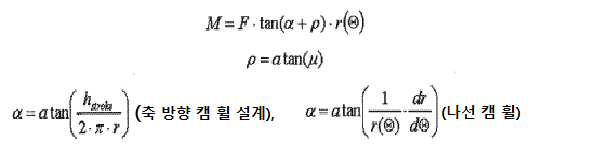
편평한 설계 토크 요구 조건.Flat design torque requirements.
우리의 경우, 후속하는 값들이 사용될 수 있다:In our case, the following values can be used:
·F = 200[mN], 스프링과 마찰을 고려하여·F = 200[mN], considering spring and friction
·hstroke = 1[㎜]H stroke = 1 [㎜]
·r = 14.5[㎜]R = 14.5 [mm]
·μ = 0.05, 강철 캠 휠, 및 테프론 피스톤을 고려하여Μ = 0.05, taking into account the steel cam wheel, and Teflon piston
이는 M = 176[μNm]인 요구된 토크를 초래한다.This results in the required torque with M = 176 [μNm].
긴 설계 토크 요구 조건.Long design torque requirements.
후속하는 파라미터들이 긴 설계를 위해 사용될 것이다.Subsequent parameters will be used for the long design.
·F = 200[mN], 스프링과 마찰을 고려하여·F = 200[mN], considering spring and friction
·hstroke = 4.5[㎜]H stroke = 4.5 [㎜]
·스프링 방정식: r(theta) = 2[㎜] + 4.5[㎜]·theta(2·π)·Spring equation: r(theta) = 2[㎜] + 4.5[㎜]·theta(2·π)
·μ = 0.05, 강철 캠 휠, 및 테프론 피스톤을 고려하여Μ = 0.05, taking into account the steel cam wheel, and Teflon piston
그러므로 휠의 각 위치의 함수로서의 토크가 도 91에 제시된다. 평균 토크는 187[μNm]이다.Therefore, the torque as a function of each position of the wheel is presented in FIG. 91. The average torque is 187 [μNm].
선형인 디스플레이를 갖는 긴 설계는 2배의 더 높은 스프링 힘을 가져야 하는데, 이는 튜브의 길이가 2배 더 길기 때문이다. 하지만, 스프링 힘은 원형 디스플레이를 갖는 경우에서 과대평가되고, 따라서 마찬가지로 선형 디스플레이에는 동일한 힘이 인가될 수 있다.A long design with a linear display should have a 2x higher spring force because the tube is 2x longer. However, the spring force is overestimated in the case of having a circular display, so the same force can be applied to the linear display as well.
양 실시예들에 관한 토크들이 도 92에 제시된다.Torques for both embodiments are presented in FIG. 92.
편평한 설계는 가장 낮은 마찰을 위해 긴 설계보다 낮은 토크를 요구하지만 다른 마찰 계수들을 갖는 더 높은 토크를 요구한다는 점이 주목할 만하다. 이는 다음과 같이 설명될 수 있다; 토크 M은 다음과 같이 계산된다:It is noteworthy that the flat design requires lower torque than the long design for the lowest friction but higher torque with different coefficients of friction. This can be explained as follows; Torque M is calculated as follows:
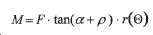
게다가, tan(α + ρ)라는 항은 다음과 같이 분해될 수 있다:Moreover, the term tan(α + ρ) can be decomposed as follows:
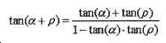
그러므로, 만약 긴 설계를 갖는 경우에서처럼 각도가 더 크다면, 마찰 각도(ρ)의 증가는 전반적인 결과에 미치는 영향이 덜 할 것이다.Therefore, if the angle is larger as in the case of having a long design, an increase in the friction angle ρ will have less effect on the overall result.
하지만, 토크 값들은 두 실시예 모두에 대해 합리적이며, 둘 모두는 마찰 계수들을 고려하였다. 이에 비해, ETA 802.001, 6 ¾" × 8" 시계 무브먼트는 분(minute) 샤프트의 전형적인 토크가 250[μNm]이다. 마찰을 고려하지 않은 시간 샤프트 상의 토크는 그것의 12배 이어야 한다. 그러므로 큰 마진(margin)이 존재한다.However, the torque values are reasonable for both examples, both taking into account friction coefficients. In comparison, the ETA 802.001, 6 ¾" × 8" watch movement has a typical torque of 250 minutes on the minute shaft. The torque on the time shaft without considering friction should be 12 times that. Therefore, there is a large margin.
동일한 무브먼트가 0.95[㎂]의 전형적인 전류 소모를 가진다. 그러므로 2년 동안 무브먼트에 전력을 제공하기 위해서는 용량이 16.6[mAh]인 배터리가 요구된다(LED와 같은 다른 요소들의 에너지 소비를 고려하지 않은).The same movement has a typical current consumption of 0.95 [µs]. Therefore, a battery with a capacity of 16.6 [mAh] is required to provide power to the movement for two years (without taking into account the energy consumption of other elements such as LEDs).
테프론 피스톤이 장치의 수명 동안 차츰 사라질 위험이 있기 때문에 텅스텐 카바이드(WC)를 고려하여 계산을 수행했으며, 특히 내구성이 높아야 하는 고급 장치를 고려했다. 사파이어-사파이어 인터페이스는 또한 낮은 마찰을 가지게 되지만, 사파이어로부터 캠들을 가공하는 것은 어려울 것이다. 하지만 텅스텐 카바이드는 사파이어만큼이나 단단하고, 이 재료로부터 많은 드릴 비트가 가공되므로 그것의 가공이 알려져 있다.Since the teflon piston is at risk of disappearing over the life of the device, tungsten carbide (WC) has been taken into account to calculate, especially for advanced devices that require high durability. The sapphire-sapphire interface also has low friction, but machining cams from sapphire will be difficult. However, tungsten carbide is as hard as sapphire, and since many drill bits are machined from this material, its processing is known.
여기서 우리는 전기습윤인 실시예 2를 기술한다.Here we describe Example 2, which is electrowetting.
또 다른 실시예에서, 전기습윤 디스플레이에 관한 단순화된 드라이버 회로의 개략적 표현이 도 93에 제시된다. 다음 요소들이 이 도면에서 보일 수 있는데, 전구(LI)는 전극의 상태에 대응한다;In another embodiment, a schematic representation of a simplified driver circuit for an electrowetting display is presented in FIG. 93. The following elements can be seen in this figure, where the light bulb LI corresponds to the state of the electrode;
공급(supply) L0은 선행 전극의 상태에 대응하고;Supply L0 corresponds to the state of the preceding electrode;
공급 L2는 다음 전극의 상태에 대응한다.Supply L2 corresponds to the state of the next electrode.
이 시스템은 언제 전환할지를 가리키는 클록 신호(CLK)와 액적이 움직여야 하는 방향을 가리키는 방향(DIRECT)의 2개의 파라미터들만이 작용할 것을 요구한다.The system requires only two parameters, the clock signal (CLK) indicating when to switch and the direction (DIRECT) indicating the direction in which the droplet should move.
전극들 자체는 도 94에 개략적으로 제시된 바와 같이 연결된다. 이러한 식으로, 각 전극을 개별적으로 어드레스하는 대신, 전극들의 3개의 그룹들로 어드레스함으로써 작용이 이루어질 수 잇다.The electrodes themselves are connected as schematically presented in FIG. 94. In this way, the action can be achieved by addressing each electrode into three groups of electrodes, instead of addressing each electrode individually.
각 전극 그룹에 관해, 2개의 더 많은 구성요소들이 이 회로의 하향으로 장착되어야 한다.For each electrode group, two more components must be mounted downward of this circuit.
유한 길이 펄스를 생성하기 위해 하나의 게이트가 불안정하게 장착되고, 전극들에 구동 전압을 인가하기 위한 하나의 릴레이(relay)가 장착된다.In order to generate a finite length pulse, one gate is mounted unstable, and one relay for applying a driving voltage to the electrodes is mounted.
여기서 단순화된 감지 회로를 기술한다. 전극들 모두에서의 완전한 감지는 선행 챕터에서 제시된 것과 같은 단순화된 구동 회로에 전극들이 연결되는 것을 허용하지 않을 것이다. 게다가, 그것은 144개의 전극들을 사용하는 것을 요구하고, 이는 전체 시스템을 전기적으로 매우 복잡하게 만들 것이다. 이러한 이유로, 도 95에 제시된 조립체가 제안된다. 이 시스템에서는 액적을 구동하기 위해, 모든 감지 전극들이 접지에 연결되고, 구동 전극들에 구동 신호가 인가된다. 액적의 위치를 탐지하기 위해 구동 전극들이 접지에 연결되고, 감지 전극들에서 피스톤이 읽어진다.A simplified sensing circuit is described here. Full sensing at all of the electrodes will not allow the electrodes to be connected to a simplified drive circuit as presented in the previous chapter. In addition, it requires the use of 144 electrodes, which will make the entire system electronically very complex. For this reason, the assembly presented in FIG. 95 is proposed. In this system, in order to drive a droplet, all sensing electrodes are connected to ground, and a driving signal is applied to the driving electrodes. The drive electrodes are connected to ground to detect the position of the droplet, and the piston is read from the sensing electrodes.
이러한 시스템은 거의 근사치인 위치만을 탐지하는 것을 허용한다. 그러므로 그것은 액적이 15분의 시간 경과에 따라 그것의 위치에 남아 있다고 안전하게 가정할 수 있는 경우에만 사용할 수 있다.Such a system allows detecting only approximate locations. Therefore, it can only be used if it can safely be assumed that the droplet remains in its position over the course of 15 minutes.
도 96에는 완전한 구동 전자장치들의 개략적인 것이 개략적으로 제시된다. 이 표현은 주요 구성 요소들과 일부 전극들을 통합한다. 모든 와이어들이 표시되는 것은 아니며 시스템을 실행하는 데 요구된 수동 구성 요소들도 표시된 것이 아니라는 점을 주목하라.96 schematically shows the complete driving electronics. This expression incorporates the main components and some electrodes. Note that not all wires are displayed, nor are the passive components required to run the system.
도 97은 시스템을 구동하기 위해 요구된 모든 구성요소들의 목록이다. 만약 이 제품이 대량 생산되어져야 한다면, 사이즈 및 비용은 커스텀(custom) IC를 개발함으로써 감소될 수 있다는 점을 주목하라. 게다가, 후자의 테이블에서 제시된 구성요소들은 최적화된 솔루션이 아니라 정리되지 않은 설계를 위한 임시 목록이다.97 is a list of all components required to run the system. Note that if this product needs to be mass produced, size and cost can be reduced by developing a custom IC. In addition, the components presented in the latter table are not optimized solutions, but are temporary lists for unorganized designs.
전기습윤 디스플레이의 구현예의 평면도 및 측면도가 전술한 구성요소들과 함께 도 98에 제시된다. 디스플레이의 길이와, 코인 셀의 폭에 관한 사이즈 한계들은 전자장치들에 관한 큰 양의 공간을 허용한다는 점이 주목할 만하다.A top view and side view of an embodiment of an electrowetting display is presented in FIG. 98 with the components described above. It is noteworthy that size limitations regarding the length of the display and the width of the coin cell allow a large amount of space for electronic devices.
게다가, 비록 이 도면에서 편평한 장치로서 제시되지만, 기판은 구부러지는(flex) 인쇄 회로일 수 있고, 이는 그것이 손목 둘레에 감싸지는 것을 허용한다는 것을 주목하라.Furthermore, note that although presented as a flat device in this figure, the substrate can be a flex printed circuit, which allows it to be wrapped around the wrist.
다음 표에는 전술한 조립체의 전력 소모의 정리되지 않은 산정치가 제시된다.The following table presents an unorganized estimate of the power consumption of the aforementioned assembly.
이 계산을 통해, 우리는 배터리들 변경없이 2년 동안 시스템이 기능을 하려면 10[mAh] 배터리 세트가 요구된다는 결론을 내릴 수 있다. 이는 표준 코인 셀들로 달성하는 것이 가능하다. 하지만, 디스플레이 자체의 전력 소비는 매우 제한적이지만 다른 구성요소들의 소비로 인해 이 솔루션이 단순한 기계적 솔루션보다 더 많은 에너지를 소비하는 것이 명백하다. 전력 소비는 이 적용예를 위해 커스텀 IC가 사용된다면 더 감소될 것이라는 점을 주목하라.From this calculation, we can conclude that a 10 [mAh] battery set is required for the system to function for 2 years without changing the batteries. It is possible to achieve this with standard coin cells. However, the power consumption of the display itself is very limited, but due to the consumption of other components, it is clear that this solution consumes more energy than a simple mechanical solution. Note that power consumption will be further reduced if a custom IC is used for this application.
설계 개념들Design concepts
아래에, 시계 무브먼트에 기초한 유체 개념들이 제시된다. 개념 1은 표준 손목 시계 케이싱의 원형 유체 채널이고, 개념 2는 유연성 있는 팔찌에 통합된 탄성이 있는 선형 유체 채널이며, 개념 3은 "S"자 모양의 디스플레이에서의 유체 채널이다.Below, fluid concepts based on a watch movement are presented.
또한 아래에 제시된 것은 전기습윤 개념이다. 개념 4는 전기습윤 설계이다.Also presented below is the concept of electrowetting.
여기서 우리는 유체 개념/시계 무브먼트 결합을 기술한다. 유체 개념은 시계 무브먼트에 기초한다. 저비용의 전기적 또는 고급의 기계적 무브먼트의 통합이 가능하다. 이는 도 99a 내지 도 99e에 도시된다.Here we describe the fluid concept/clock movement combination. The fluid concept is based on a watch movement. Integration of low-cost electrical or high-grade mechanical movements is possible. This is illustrated in FIGS. 99A-99E.
여기서 우리는 유체 개념/조립체를 기술한다. 캠 휠이 무브먼트의 시간 피팅(hour fitting)(902)에서 조립된다. 유체 채널의 조립체는 저장기와 필링(filling)(904)에 결합된다. OEM 무브먼트들을 위한 것으로서 기계적인 기준들을 가지고 시계 케이싱에서의 조립에 이루어진다. 대응하는 피팅들 또는 추가적인 무브먼트에 기초한 시간 복잡화에서 초침들의 조립이 가능하다. 이는 도 100a 내지 도 100d에 도시된다.Here we describe the fluid concept/assembly. The cam wheel is assembled at the hour fitting 902 of the movement. The assembly of fluid channels is coupled to reservoir and filling 904. For OEM movements, it is assembled in a watch casing with mechanical standards. Assembly of the second hand is possible in time complexity based on corresponding fittings or additional movements. This is illustrated in FIGS. 100A-100D.
여기서 개념 1을 기술한다. 표준 손목 시계 케이싱에서의 원형 유체 채널. 그 설계는 "정상적인" 손목 시계에 가까울 수 있다. 원형 채널을 케이싱에 있다. 유체 설계는 외측으로부터 보호된다. 디스플레이 창(window)의 아래, 위 또는 내측에서 가변적인 채널 모양이 가능하다. 유체/기계적인 조립체의 디스플레이가 가능하다. 고급 시계 메커니즘 또는 복잡화의 디스플레이가 가능하다.
시계에 개념 1을 통합하는 것이 도 101a 내지 도 101f에 도시된다. 도 102a는 오전 6시/오후 6시가 중심에 있는 355°의 디스플레이 변형예를 도시한다. 도 102b는 유체 메커니즘이 중심에 있는 330°의 디스플레이 변형예를 도시한다. 도 102c는 채널이 반경을 따라 팽창하면서 시간 길이가 증가하는 360°의 디스플레이 변형예를 도시한다.Incorporating
여기서 우리는 개념 2를 기술한다. 유연성이 있는 팔찌에 탄성이 있는 선형 유체 채널이 통합된다. 이 설계는 시계에 비해 "반전된(reversed)" 것으로 그 케이싱은 손목 아래에 착용된다. 채널은 팔찌에 있고 팔찌와 채널 모두 탄성이 있다. 팔찌는 열릴 수 없다. 팔찌는 고정 클립들을 가지고 있지 않다. 사용자는 사용자의 손목에 맞추기 위해 팔찌를 손가락들과 손바닥에 걸쳐 늘려야 한다. 채널을 손목 둘레에서 원 모양을 하고 있고, 이중으로 감기거나 상이한 모양을 가질 수 있다. 유체 설계는 외측으로부터 보호되지 않는다. 그것은 다중의 스트레칭 사이클들에 저항해야 한다. 만약 사용자가 채널 상에 압력을 가하면 메커니즘이 손상될 수 있다. 케이싱의 앞측가 뒤측은 메커니즘을 보여주기 위해 투명할 수 있다. 개념 2의 통합은 도 103a 내지 도 103h에 도시된다.Here we describe
여기서 우리는 탄성 있는 선형 개념 변형예에서의 개념 2를 기술한다. 메커니즘은 또한 케이싱 내측에 초침과 분침을 포함할 수 있다. 캠 휠(시침)은 표시기(시침)을 통합할 수 있다. 시계는 팔찌에서의 유체 시간 디스플레이를 가지게 되고 손목 아패의 케이싱에서 핸즈 디스플레이(hands display)를 가지게 된다. 이 개념은 도 104에 도시된다.Here we describe
여기서 우리는 개념 2B를 기술한다. 이 시계는 폐쇄 루프 팔찌에서의 유체 채널이 있는 개념 1로서 착용될 수 있다. 이 개념은 도 105에 도시된다.Here we describe Concept 2B. This watch can be worn as a
여기서 우리는 개념 3A를 기술한다. 유체 채널은 "S"자 모양 디스플레이에 있다. 그 설계는 시계에 비해 "반전"되고, 그 케이싱은 손목 아래에서 착용된다. 채널은 팔지에 있고, 팔찌와 채널 모드 반탄력적(semi-elastic)이다. 팔찌는 열릴 수 없다. 팔찌는 고정 클립들을 가지고 있지 않다. 사용자는 손가락들과 손바닥에 걸쳐 팔찌와 디스플레이를 늘임으로써 그것을 착용한다. 채널 유리는 손목 둘레에 있다. 유체 설계는 외측으로부터 보호되지 않는다. 그것은 다중 스트레칭 사이클들에 저항해야 한다. 메커니즘은 만약 사용자가 채널에서 압력을 가한다면 손상될 수 있다. 케이싱의 앞측 및 뒤측은 그러한 메커니즘을 보여주기 위해 투명할 수 있다. 이 개념은 도 106a 내지 도 106f에 도시된다.Here we describe Concept 3A. The fluid channel is on an "S" shaped display. The design is "inverted" compared to a watch, and the casing is worn under the wrist. The channel is on the arm, and the bracelet and channel mode are semi-elastic. The bracelet cannot be opened. The bracelet does not have retaining clips. The user wears it by stretching the bracelet and display across fingers and palms. The channel glass is around the wrist. The fluid design is not protected from outside. It must resist multiple stretching cycles. The mechanism can be damaged if the user applies pressure on the channel. The front and back sides of the casing can be transparent to show such a mechanism. This concept is illustrated in FIGS. 106A-106F.
여기서 우리는 개념 3B를 기술한다. 채널은 개방 시스템을 갖는 "S"자 디스플레이에 있다. 채널은 2배가 되고 케이싱에서 감압 챔버로 다시 향하는 리턴 브랜치(return branch)를 가진다. 팔찌는 다른 브랜치에서 열릴 수 있다. 채널은 부분적으로 손목 둘레에 있다. 유체 설계는 외측으로부터 보호되지 않는다. 그것은 다중 스트레칭 사이클들에 저항해야 한다. 만약 사용자가 채널에서 압력을 가하면 메커니즘이 손상될 수 있다. 케이싱의 앞측과 뒤측은 메커니즘을 보여주기 위해 투명할 수 있다. 개념 3B는 개념 3A에 관해서는 가능하지 않은 디스플레이 케이싱 상호교환 가능성(고급)을 허용한다. 이 개념은 도 107에 도시된다.Here we describe Concept 3B. The channel is in an "S" shaped display with an open system. The channel is doubled and has a return branch from the casing back to the decompression chamber. Bracelets can be opened in different branches. The channel is partially around the wrist. The fluid design is not protected from outside. It must resist multiple stretching cycles. If the user applies pressure on the channel, the mechanism may be damaged. The front and back sides of the casing can be transparent to show the mechanism. Concept 3B allows for the possibility (advanced) of display casing interchangeability not possible with respect to Concept 3A. This concept is illustrated in FIG. 107.
여기서 우리는 전기습윤 개념을 기술한다. 이는 여기서 개념 4라고 부른다. 유체 개념은 전기습윤에 기초한다. 그것은 용량성 감지와, 동일한 전극들을 갖는 작용(actuation)을 사용한다. 그 설계는 직사각형 채널에 기초한다. 조립은 층상으로 이루어져 구부러짐(bending)을 허용한다.Here we describe the concept of electrowetting. This is called
도 108은 투명한 ITO 전극들과 전가 구성요소들을 갖는 PCB를 보여준다. 도 109a 및 도 109b는 도 108의 세부 사항(A)을 보여준다. 도 109a에서는 감지 전극들이 강조된다. 도 109b에서는 구동 전극들이 강조된다. 도 110은 예컨대 도 43, 도 45, 도 71에서 제공된 것과 같은 전기습윰의 개략적인 것을 도시한다. 구동 전가장치들의 완전한 개략적인 것을 보여주는 도 96에 대한 참조가 이루어진다.108 shows a PCB with transparent ITO electrodes and imputation components. 109A and 109B show details (A) of FIG. 108. In Figure 109a, the sensing electrodes are highlighted. In Figure 109b, the driving electrodes are highlighted. FIG. 110 shows a schematic diagram of the electrowetting as provided for example in FIGS. 43, 45, and 71. Reference is made to FIG. 96, which shows a complete schematic of drive transmissions.
개념 4는 다음 변형예들을 가질 수 있다. 개념 4A에서는 손목 둘레의 타임라인(timeline)이 개념 2와 유사하다. 이 설계는 늘어날 수 없다. 그러므로 시계는 기존의 클리핑(clipping) 팔찌를 가진다. 개념 4B에서는 시간이 표준 시계 케이싱에서 디스플레이된다. 3개의 액적들이 상이한 채널들에서 움직여진다. 각각의 채널은 스케일링(scaling)을 가지고 3개의 동심 원들에서 초, 분 및 시를 나타낸다.
도 111은 팔찌 기반의 전기습윤에서의 시간의 표시를 보여준다. 도 112는 도 111의 시간 표시를 상세하게 도시한다. 도 113은 팔찌에 관한 폐쇄 장치들을 도시한다.111 shows an indication of time in bracelet-based electrowetting. FIG. 112 shows the time display of FIG. 111 in detail. 113 shows closure devices for the bracelet.
본 발명(들)은 다음 특징 세트들에 의해 요약될 수 있다.The invention(s) can be summarized by the following feature sets.
1. 유체를 포함하는 유체 디스플레이용 장치에 있어서, 상기 제2 제어 전극의 상기 전기적 활성화가 상기 제2 제어 전극의 방향으로 상기 유체의 변형 또는 이동을 발생시키도록, 상기 유체는 전기습윤 프로세스에 의해 변위되고, 상기 장치는 적어도 2개의 섞일 수 없는 유체들로 채워지는데 반해, 하나의 유체는 기준 전극과 제어 전극에 의해 발생되는 상기 전기장 내에 위치하고 동일한 기준 전극과 적어도 하나의 제2 제어 전극에 의해 발생되는 상기 전기장 내에 부분적으로 위치한다.1. In a fluid display device comprising a fluid, the fluid is subjected to an electrowetting process such that the electrical activation of the second control electrode causes deformation or movement of the fluid in the direction of the second control electrode. Displaced, the device is filled with at least two immiscible fluids, while one fluid is located in the electric field generated by the reference electrode and the control electrode and is generated by the same reference electrode and at least one second control electrode Being partially located within the electric field.
2. 특징 세트 1의 장치에 있어서, 상기 변위되는 유체는 액체의 적어도 하나의 액적이다.2. In the device of feature set 1, the displaced fluid is at least one droplet of liquid.
3. 특징 세트 1의 장치에 있어서, 상기 유체들은 투명하거나 반투명하거나 불투명하다.3. In the device of feature set 1, the fluids are transparent, translucent or opaque.
4. 특징 세트 1의 장치에 있어서, 상기 유체들은 애니메이션(animation)을 보여준다.4. In the device of feature set 1, the fluids show animation.
5. 특징 세트 1의 장치에 있어서, 상기 유체들은 측정된 값을 나타내기 위해 표시(indicia)를 따라 이동한다.5. In the device of feature set 1, the fluids move along an indicia to indicate the measured value.
6. 특징 세트 1의 장치에 있어서, 상기 기준 전극은 나누어지지 않거나 여러 부분들로 나누어진다.6. In the device of feature set 1, the reference electrode is not divided or divided into several parts.
7. 특징 세트 1의 장치에 있어서, 상기 기준 전극은 상기 유체들과 직접 전기 접촉하거나 상기 유체들로부터 격리된다.7. In the device of feature set 1, the reference electrode is in direct electrical contact with or isolated from the fluids.
8. 특징 세트 1의 장치에 있어서, 상기 제어 전극들은 유전층(dielectric layer)에 의해 상기 유체들로부터 격리된다.8. In the device of feature set 1, the control electrodes are isolated from the fluids by a dielectric layer.
9. 특징 세트 1의 장치에 있어서, 상기 기준 전극은 상기 제어 전극들의 상기 표면 반대쪽에 위치하고/위치하거나 상기 제어 전극들의 상기 표면에 인접하게 위치한다.9. In the device of feature set 1, the reference electrode is positioned opposite the surface of the control electrodes and/or adjacent to the surface of the control electrodes.
10. 상기 유체의 일부가 상기 장치 내에서 변위되도록 특징 세트 1의 장치의 상기 제어 전극들을 순서대로(in a sequence) 스위칭하는 방법.10. A method of switching the control electrodes of a device of feature set 1 in a sequence such that a portion of the fluid is displaced within the device.
11. 특징 세트 10의 방법에 있어서, 상기 제어 전극들은 AC 전압 또는 DC 전압에 의해 활성화된다.11. In the method of feature set 10, the control electrodes are activated by AC voltage or DC voltage.
12. 상기 제어 전극들에 대한 상기 유체의 상기 위치가 탐지되도록 특징 세트 1의 장치의 상기 제어 전극들에 전력을 순서대로 공급하는 방법.12. A method of sequentially supplying power to the control electrodes of the device of feature set 1 so that the position of the fluid relative to the control electrodes is detected.
13. 특징 세트 5의 장치를 포함하는 장치로서, 모든 전극들은 투명하고 상기 전극들 밑에 상기 표시가 놓인다.13. A device comprising the device of feature set 5, all electrodes are transparent and the mark is placed under the electrodes.
14. 특징 세트 13의 장치에 있어서, 상기 사용자가 상기 사용자의 장치를 커스터마이즈(customize)하기 위해 상호 교환 가능한 표시(interchangeable indicia)가 제공된다.14. In the device of feature set 13, an interchangeable indicia is provided for the user to customize the user's device.
15. 특징 세트 1 내지 특징 세트 14 중 어느 하나에 따른 장치를 포함하는 시계(timepiece)로서, 상기 측정된 값은 시간(time)이다.15. A timepiece comprising a device according to any one of feature set 1 to feature set 14, wherein the measured value is time.
16. 특징 세트 1의 장치에 있어서, 상기 제2 제어 전극의 상기 전기적 활성화가 상기 제2 제어 전극의 상기 방향으로 상기 유체의 변형 또는 이동을 발생시키도록 적어도 2개의 섞일 수 없는 유체들로 채워지는데 반해, 하나의 유체는 기준 전극과 제어 전극에 의해 발생되는 상기 전기장 내에 위치하고 동일한 기준 전극과 적어도 하나의 제2 제어 전극에 의해 발생되는 상기 전기장 내에 부분적으로 위치한다.16. The device of feature set 1, wherein the electrical activation of the second control electrode is filled with at least two immiscible fluids to cause deformation or movement of the fluid in the direction of the second control electrode. In contrast, one fluid is located in the electric field generated by the reference electrode and the control electrode and partially located in the electric field generated by the same reference electrode and the at least one second control electrode.
17. 특징 세트 16의 장치에 있어서, 상기 변위되는 유체는 액체의 적어도 하나의 액적이다.17. In the device of feature set 16, the displaced fluid is at least one droplet of liquid.
18. 특징 세트 16의 장치에 있어서, 상기 유체들은 투명하거나 반투명하거나 불투명하다.18. In the device of feature set 16, the fluids are transparent, translucent or opaque.
19. 특징 세트 16의 장치에 있어서, 상기 유체들은 애니메이션을 보여준다.19. In the device of feature set 16, the fluids show animation.
20. 특징 세트 16의 장치에 있어서, 상기 유체들은 측정된 값을 나타내기 위해 표시를 따라 이동한다.20. In the device of feature set 16, the fluids move along the indicia to indicate the measured value.
21. 특징 세트 17의 장치에 있어서, 상기 기준 전극은 나누어지지 않거나 여러 부분들로 나누어진다.21. In the device of feature set 17, the reference electrode is not divided or divided into several parts.
22. 특징 세트 17의 장치에 있어서, 상기 기준 전극은 상기 유체들과 직접 전기 접촉하거나 상기 유체들로부터 격리된다.22. In the device of feature set 17, the reference electrode is in direct electrical contact with or isolated from the fluids.
23. 특징 세트 17의 장치에 있어서, 상기 제어 전극들은 유전층에 의해 상기 유체들로부터 격리된다.23. In the device of feature set 17, the control electrodes are isolated from the fluids by a dielectric layer.
24. 특징 세트 17의 장치에 있어서, 상기 기준 전극은 상기 제어 전극들의 상기 표면 반대쪽에 위치하고/위치하거나 상기 제어 전극들의 상기 표면에 인접하게 위치한다.24. In the device of feature set 17, the reference electrode is located opposite and/or adjacent to the surface of the control electrodes.
25. 상기 유체의 일부가 상기 장치 내에서 변위되도록 특징 세트 17의 장치의 상기 제어 전극들을 순서대로 스위칭하는 방법.25. A method of sequentially switching the control electrodes of a device of feature set 17 such that a portion of the fluid is displaced within the device.
26. 특징 세트 25의 방법에 있어서, 상기 제어 전극들은 AC 또는 DC 전압에 의해 활성화된다.26. In the method of feature set 25, the control electrodes are activated by AC or DC voltage.
27. 상기 제어 전극들에 대한 상기 유체의 상기 위치가 탐지되도록 특징 세트 17의 표시기의 상기 제어 전극들에 전력을 순서대로 공급하는 방법.27. A method of sequentially supplying power to the control electrodes of the indicator of feature set 17 so that the position of the fluid with respect to the control electrodes is detected.
28. 특징 세트 21의 장치를 포함하는 장치로서, 모든 전극들은 투명하고 상기 전극들 밑에 상기 표시가 놓인다.28. A device comprising the device of feature set 21, wherein all electrodes are transparent and the mark is placed under the electrodes.
29. 특징 세트 28의 장치에 있어서, 상기 사용자가 상기 사용자의 장치를 커스터마이즈하기 위해 상호 교환 가능한 표시가 제공된다.29. In the device of feature set 28, an interchangeable indication is provided for the user to customize the user's device.
30. 특징 세트 1 내지 특징 세트 29 중 어느 하나에 따른 장치를 포함하는 시계로서, 상기 측정된 값은 시간이다.30. A watch comprising a device according to any one of feature sets 1 to 29, wherein the measured value is time.
31. 측정된 값을 표시하거나 심미적 모양(aesthetic shape)을 생성하는 유체를 포함하는 장치에 있어서, 상기 제2 제어 전극의 상기 전기적 활성화가 상기 제2 제어 전극의 상기 방향으로 상기 유체의 변형 또는 이동을 발생시키도록 상기 유체는 전기습윤 프로세스에 의해 변위되고, 상기 장치는 적어도 2개의 섞일 수 없는 유체들로 채워지는데 반해 하나의 유체는 기준 전극과 제어 전극에 의해 발생되는 상기 전기장 내에 위치하고 동일한 기준 전극과 적어도 하나의 제2 제어 전극에 의해 발생되는 상기 전기장 내에 부분적으로 위치하고, 선택적으로(optionally) 적어도 하나의 제어 전극은 .01㎜보다 큰 사이즈를 가지고 사람의 눈에 의해 보여지기에 충분하게 매우 크다.31. In a device comprising a fluid displaying a measured value or creating an aesthetic shape, the electrical activation of the second control electrode is such that the fluid is deformed or moved in the direction of the second control electrode. The fluid is displaced by an electrowetting process to generate a, and the device is filled with at least two immiscible fluids, while one fluid is located within the electric field generated by the reference electrode and the control electrode and the same reference electrode. And partially located within the electric field generated by the at least one second control electrode, and optionally, at least one control electrode has a size greater than .01 mm and is very large enough to be seen by the human eye. .
32. 특징 세트 19의 장치에 있어서, 심미적 모양을 나타내기 위해 설계되는 적어도 하나의 제어 전극이 존재한다.32. In the device of feature set 19, there is at least one control electrode designed to exhibit an aesthetic appearance.
33. 특징 세트 32의 장치에 있어서, 상기 유체 액적들을 모아서 그것들을 상기 제어 전극들이 상기 심미적 모양을 형성하는 영역으로 안내하는 역할을 하는 제어 전극들이 존재한다.33. In the device of feature set 32, there are control electrodes that serve to collect the fluid droplets and direct them to an area where the control electrodes form the aesthetic shape.
34. 다른 유체의 적어도 하나의 폐쇄된 섹션(closed section)을 얻기 위해 상기 유체가 변형되도록 특징 세트 33의 장치의 상기 제어 전극들을 스위칭하는 방법.34. A method of switching the control electrodes of the device of feature set 33 such that the fluid is deformed to obtain at least one closed section of another fluid.
35. 상기 유체 액적이 2개 이상의 액적들로 분리되도록 특징 세트 34의 표시기의 상기 제어 전극들을 스위칭하는 방법.35. A method of switching the control electrodes of the indicator of feature set 34 such that the fluid droplet is separated into two or more droplets.
36. 유체를 포함하는 유체 디스플레이용 장치에 있어서, 상기 유체는 전기습윤 프로세스에 의해 변위되고, 상기 장치는 적어도 2개의 섞일 수 없는 유체들로 채워지는데 반해 하나의 유체는 제어 전극에 의해 발생되는 전기장에 의해 활성화되고 상기 전극의 활성화는 상기 유체들 중 적어도 하나의 변형 또는 이동을 발생시킨다.36. In a device for a fluid display comprising a fluid, the fluid is displaced by an electrowetting process, and the device is filled with at least two immiscible fluids, whereas one fluid is an electric field generated by a control electrode. And activation of the electrode causes deformation or movement of at least one of the fluids.
본 발명은 착용 가능한 장치일 수 있고, 적어도 하나의 능동 액체와 수동 유체로 이루어진 유체 디스플레이를 포함한다. 적어도 하나의 유체는 본 명세서에서 기술된 바와 같은 입력 행위에 의해 움직이게 된다. 유체(들)의 운동은 애니메이션 또는 표시(indication)의 형태로 될 수 있다. 유체(들)의 운동은 또한 3D 효과를 생성할 수 있다.The present invention can be a wearable device and includes a fluid display consisting of at least one active liquid and a passive fluid. At least one fluid is moved by an input action as described herein. The motion of the fluid(s) can be in the form of animation or indication. The motion of the fluid(s) can also produce a 3D effect.
능동 유체는 극성 용매이고, 수동 유체와 혼합되지 않으며, 높은 표면 에너지를 갖는다. 수동 유체는 낮은 에너지 표면을 가지고 능동 액체와 혼합되지 않으며, 낮은 점도를 가진다. 수동 유체는 기체이거나 액체일 수 있고, 만약 그것이 액체로서 본 발명에서 사용된다면 그것은 바람직하게는 무극성/비극성 용매이다.The active fluid is a polar solvent, does not mix with passive fluids, and has a high surface energy. Passive fluids have a low energy surface, do not mix with active liquids, and have a low viscosity. The passive fluid can be gas or liquid, and if it is used in the present invention as a liquid it is preferably a non-polar/non-polar solvent.
능동 액체는 -20℃ 미만의 융점 및 +80℃ 초과의 끓는점을 갖는다. 주위 온도에서 액체 형태로 본 발명에서 사용되는 수동 유체는 -20℃ 미만의 융점 및 +80 ℃ 초과의 끓는점을 갖는다. 수동 유체는 만약 본 발명에서 주위 온도에서 기체의 형태로 사용된다면 -20℃ 미만의 끓는점을 가진다.The active liquid has a melting point below -20°C and a boiling point above +80°C. The passive fluid used in the present invention in liquid form at ambient temperature has a melting point below -20°C and a boiling point above +80°C. Passive fluids have a boiling point below -20°C if used in the form of a gas at ambient temperature in the present invention.
눙동 액체 및/또는 수동 액체의 계면 활성제는 투명하고, 개시된 온도 범위에서 화학적으로 안정하고, 인접한 유전체로의 확산 속도가 낮고, 분자 크기가 크며, 전기장들에 대해 튼튼하다. 계면 활성제들은 이온성(예컨대, 양이온성, 양쪽이 온성 또는 음이온성) 또는 비이온성일 수 있다. 계면 활성제들은 시스템의 작동 전압을 낮춘다.The surfactants of the copper and/or passive liquids are transparent, chemically stable in the disclosed temperature range, low diffusion rate to adjacent dielectrics, large molecular size, and robust against electric fields. Surfactants can be ionic (eg, cationic, both ionic or anionic) or nonionic. Surfactants lower the operating voltage of the system.
수동 및/또는 능동 액체들인 액체들은 투명하거나 착색될 수 있다. 만약 착색되면, 착색제가 이온성(예컨대, 양이온성, 양쪽이 온성 또는 음이온성) 또는 비이온성일 수 있다. 착색제는 분자 크기기 큰 것일 수 있고, 개시된 온도 범위에서 화학적으로 안정하며, 인접한 유전체로의 확산 속도가 낮고, 전기장들에 대해 튼튼하고, 유체들 사이에서 높은 콘트라스트를 허용하고, 특히 수동 유체와 능동 유체 사이에 높은 콘트라스트를 허용하며, 양호한 용해도 특성들을 가진다. 착색제는 예컨대 유기 다이(die), 양자 점들, 무기 다이 또는 안료들의 타입의 것일 수 있다.Liquids that are passive and/or active liquids can be transparent or colored. If colored, the colorant can be ionic (eg, cationic, both ionic or anionic) or nonionic. The colorant may be of a large molecular size, is chemically stable in the disclosed temperature range, has a low diffusion rate to adjacent dielectrics, is strong against electric fields, allows high contrast between fluids, and is particularly active with passive fluids. It allows high contrast between fluids and has good solubility properties. The colorant can be, for example, an organic die, quantum dots, inorganic die or a type of pigments.
본 발명에서 제공된 공동들은 세라믹, 폴리머, 또는 유리, 그리고 특히 사파이어 유리로 만들어질 수 있다. 공동은 채널 형태인 경우 에칭될 수 있고, 챔버 형태인 경우, 플레이트 내에서 에칭되고 빌드(build)되거나 내부 다이어리 층들로 만들어질 수 있다. 공동은 추가 에칭 단계, 층 증착 및 구조화 단계, 또는 핫 엠보싱 단계에 의해 개선될 수 있다. 공동의 내부 표면은 거칠기가 낮다.The cavities provided in the present invention can be made of ceramic, polymer, or glass, and in particular sapphire glass. The cavity can be etched in the form of a channel, and in the form of a chamber, etched and built in a plate or made of inner diary layers. The cavity can be improved by additional etching steps, layer deposition and structuring steps, or hot embossing steps. The inner surface of the cavity has a low roughness.
공동을 수용하는데 사용되는 기판은 중합체들, 또는 유리, 특히 사파이어 유리로 만들어 질 수 있으며, 공동을 보는 사용자의 시야 방향에서 적어도 실질적으로 투명하다. 기판은 직사각형인 것, 원형인 것, 내부 영역(예를 들어, 중심)에 개구부(예를 들어, 구멍) 또는 임의의 다른 적절한 기하학적 구조를 갖는 원형인 것일 수 있다. 기판은 또한 공통 전극 또는 제어 전극으로서 기능할 수 있다.The substrate used to receive the cavity can be made of polymers, or glass, especially sapphire glass, and is at least substantially transparent in the viewing direction of the user viewing the cavity. The substrate may be rectangular, circular, circular with openings (eg, holes) in any interior region (eg, center) or any other suitable geometry. The substrate can also function as a common electrode or a control electrode.
하지만, 본 발명에서 제안된 공통 및/또는 제어 전극들은 금속(예컨대, 금 또는 크롬) 또는 예컨대, ITO(indium tin oxide)와 같은 투명한 전도성 막(TCF)으로 만들어질 수 잇다. 전극들은 낮은 저항성을 가진다. 전극들은 의도된 작동 조건에서, 특히 의도된 작동 온도 범위에서 융합하지 않고 균열들을 형성하지 않도록 구성된다. 유전체 층은 핀 홀을 요구하지 않고 컨포멀(conformal)하다.However, the common and/or control electrodes proposed in the present invention can be made of metal (eg, gold or chromium) or a transparent conductive film (TCF), such as indium tin oxide (ITO). The electrodes have low resistance. The electrodes are configured so that they do not fuse and form cracks at the intended operating conditions, especially at the intended operating temperature range. The dielectric layer is conformal without requiring a pin hole.
전극들로의 전기적 연결들은 내부 또는 외부에 위치하고, TGA(through glass via)로서 실현될 수 있다. 전극 마다의 다중 연결들이 가능하다. 연결에 적합한 커넥터(connector)들에는 Zebra 커넥터, Flex 커넥터 또는 Pogo 핀들이 있다.Electrical connections to the electrodes are located inside or outside and can be realized as a through glass via (TGA). Multiple connections per electrode are possible. Suitable connectors are Zebra connectors, Flex connectors or Pogo pins.
유전층은 단층 또는 다층일 수 있고, 유기 물질 또는 산화물 층으로 만들어 질 수 있으며, 실질적으로 투명하다. 유전체는 물리 기상 증착(PVD), 분자 기상 증착(MVD), 플라즈마 강화 화학 기상 증착(PE-CVD) 또는 원자 층 증착(ALD)에 의해 적용될 수 있다.The dielectric layer can be a single layer or multiple layers, can be made of an organic material or oxide layer, and is substantially transparent. The dielectric can be applied by physical vapor deposition (PVD), molecular vapor deposition (MVD), plasma enhanced chemical vapor deposition (PE-CVD) or atomic layer deposition (ALD).
유체와 접촉하는 표면에 포빅(phobic) 코팅이 적용될 수 있다. 코팅은 소수성 및 올레오포빅(oleophobic) 코팅이다. 또, 코팅은 히스테리시스가 낮고 개시된 온도 범위에서 화학적으로 안정하다. 코팅에 구조를 적용하는 것이 가능하다. 코팅은 분자 기상 증착(MVD), 침지, 플러싱, 스핀 코팅 또는 분무에 의해 증착된다. 증착된 코팅은 일정한 두께를 가지고 균일하며 실질적으로 투명하며 컨포멀하다. 적합한 물질은 플루오로중합체, 플루오로중합체를 갖는 실란, 또는 알칸 체인들이다. 코팅은 임의로, 예를 들어 열 경화 또는 자외선 경화(UV 경화)에 의해 경화될 수 있다.A phobic coating can be applied to the surface in contact with the fluid. The coating is a hydrophobic and oleophobic coating. In addition, the coating has low hysteresis and is chemically stable in the disclosed temperature range. It is possible to apply the structure to the coating. The coating is deposited by molecular vapor deposition (MVD), dipping, flushing, spin coating or spraying. The deposited coating is uniform, substantially transparent and conformal with a constant thickness. Suitable materials are fluoropolymers, silanes with fluoropolymers, or alkane chains. The coating can optionally be cured, for example by thermal curing or ultraviolet curing (UV curing).
본 발명의 조립은 다음의 조립 작업을 포함할 수 있다. 공동은 레이저, 워터젯, SACE 또는 재봉에 의해 기판 플레이트로 절단된다. 플레이트는 레이저 용접, 양극 접합, 융합 접합, 접착 또는 초음파 용접에 의해 조립된다. 플레이트의 조립은 플레이트들 사이의 우수한 접착력, 낮은 수축률, 화학적 안정성, 서브 층들 무결성을 요구하고, 팽창이 회피되어야 하며, 견고함이 보장되고 기포를 회피해야 한다. 플레이트들의 조립은 공통 전극을 갖는 플레이트 및 제어 전극을 갖는 플레이트의 조립을 포함하지만 이에 국한되는 것은 아니다. 조립된 플레이트에 의해 형성된 적어도 하나의 공동은 인가된 진공 및 능동 미세액적 주입에 의해 프라이밍된다. 프라이밍 동안에, 조립된 플레이트들은 기포들이 완전히 회피되도록 배향되어야 한다. 프라이밍 후, 밀봉 단계가 적용된다. 개구부는 접착, 레이저 용접, 또는 나사 또는 프레스 핏(press fit)의 삽입에 의해 밀봉될 수 있다. 밀봉 중에도 기포는 완전히 회피되어야 한다.Assembly of the present invention may include the following assembly operations. The cavity is cut into the substrate plate by laser, waterjet, SACE or sewing. Plates are assembled by laser welding, anodizing, fusion bonding, gluing or ultrasonic welding. Assembly of the plate requires good adhesion between the plates, low shrinkage, chemical stability, integrity of the sub-layers, expansion should be avoided, tightness guaranteed and air bubbles avoided. Assembly of plates includes, but is not limited to, assembly of a plate with a common electrode and a plate with a control electrode. At least one cavity formed by the assembled plate is primed by applied vacuum and active microdroplet injection. During priming, the assembled plates must be oriented so that the bubbles are completely avoided. After priming, a sealing step is applied. The opening can be sealed by gluing, laser welding, or inserting a screw or press fit. Air bubbles should be completely avoided even during sealing.
유체들 중 하나, 특히 능동 유체의 위치 및/또는 존재의 탐지는 (RC- 회로에서) 전송/응답 시간, 단위 펄스 응답 또는 펄스 통합과 같은 용량성 탐지 방법에 의해 실현될 수 있다. 신호 처리는 ASIC(application specific integrated circuit), FPGA(field programmable gate arrays) 또는 기존의 디지털 신호 처리(DSP) 유닛에 의해 행해질 수 있다.Detection of the location and/or presence of one of the fluids, particularly the active fluid, can be realized by capacitive detection methods such as transmission/response time (in the RC-circuit), unit pulse response or pulse integration. The signal processing can be done by application specific integrated circuit (ASIC), field programmable gate arrays (FPGA) or existing digital signal processing (DSP) units.
본 발명은 유체들의 제어를 허용하고 그로 인해 애니메이션을 발생시킨다. 액적은 전극 성형(shaping)에 의해 또는 채널의 형태에 의해 변형될 수 있다. 액적들은 단일 및 개별 액적뿐만 아니라 액적들의 그룹(여러 액적들)으로도 조작할 수 있다. 액적들은 추가로 병합(fusion) 및 분할(division)될 수 있다. 유체들(및 액적)은 숨겨진 저장기들로 이동될 수 있다. 사용자는 필요에 따라 그러한 애니메이션을 시작할 수 있다. 유체들은 전자 및 전극을 통해 제어된다. 전극은 AC, 비-정현파 AC, DC 및 준(quasi)-DC와 같은 전극 파형들을 생성 및 적용하여 전자기 간섭들과 관련된 요건들을 존중할 수 있다. 전자 장치는 ASIC, FPGA, 또는 종래의 디지털 신호 처리(DSP) 유닛에 통합되거나 부분적으로 통합 될 수 있다. 전자 장치는 마이크로컨트롤러, 타이밍 제어기, 전력 관리 시스템(예컨대, DCDC 스텝-업(step-up)을 제어하기 위해), 액적 탐지 모세관들, 사용자 인터페이스 제어기 및 전극들로의 인가 전압과 액적기들 드라이버를 제공한다. 액적들의 안정성은 낮은 전압을 인가하고 공동의 적합한 모양을 실현하며, 밀도가 일치하는 액체들을 선택함으로써 시스템의 액적이 충격을 받고 중력 및 임의의 다른 가속력에 저항할 수 있게 함으로써 제어될 수 있다.The present invention allows control of fluids and thereby creates animation. The droplets can be deformed by electrode shaping or by channel shape. The droplets can be manipulated with single and individual droplets as well as groups of droplets (multiple droplets). The droplets can be further fusion and divided. Fluids (and droplets) can be moved to hidden reservoirs. The user can start such an animation as needed. Fluids are controlled via electrons and electrodes. The electrode can generate and apply electrode waveforms such as AC, non-sinusoidal AC, DC and quasi-DC to respect the requirements related to electromagnetic interferences. The electronic device can be integrated into or partially integrated into an ASIC, FPGA, or conventional digital signal processing (DSP) unit. Electronic devices include microcontrollers, timing controllers, power management systems (e.g., to control DCDC step-ups), droplet detection capillaries, user interface controllers and applied voltages to electrodes and droplet drivers Provides The stability of the droplets can be controlled by applying a low voltage, realizing a suitable shape of the cavity, and by selecting liquids of a consistent density, the droplets of the system can be impacted and resist gravity and any other acceleration.
본 발명의 실현을 위해 사용된 재료들은 본 발명의 작동 온도 범위에 적합하고 순응하도록 선택된다. 그러한 재료들에는 예컨대, 금속들, 폴리머들 또는 유리, 그리고 특히 사파이어 유리가 있다. 본 발명의 실현에 사용되는 구조들 관해서는 동등하게, 예를 들어 벨로우즈, 칩들 또는 고유 멤브레인들은 본 발명의 작동 온도 범위에 적합하고 순응하도록 구성된다.The materials used for the realization of the present invention are selected to fit and conform to the operating temperature range of the present invention. Examples of such materials are metals, polymers or glass, and in particular sapphire glass. Equally as to the structures used in the realization of the present invention, for example bellows, chips or intrinsic membranes are configured to conform and conform to the operating temperature range of the present invention.
첨부된 부록에서는 다른 실시예들이 도시되고 기술되며, 이러한 부록은 이러한 쓰여진 기술에서 본 명세서에 통합된다.Other embodiments are shown and described in the appended annexes, which are incorporated herein in this written description.
본 명세서에 도시되고 설명된 특정 구현들은 본 발명 및 그 최상의 모드를 대표하며 어떠한 방식으로도 본 발명의 범위를 제한하려는 것이 아님을 이해해야 한다. 또한, 본 명세서에 포함된 다양한 도면에 도시된 연결 라인들은 다양한 요소들 사이의 예시적인 기능적 관계 및/또는 물리적 결합들을 나타내도록 의도된다. 많은 대안적 또는 추가적인 기능적 관계들 또는 물리적 연결들이 실제 시스템에 존재할 수 있음에 유의해야 한다.It should be understood that the specific implementations shown and described herein represent the invention and its best mode and are not intended to limit the scope of the invention in any way. In addition, the connection lines shown in the various figures included herein are intended to represent exemplary functional relationships and/or physical couplings between various elements. It should be noted that many alternative or additional functional relationships or physical connections may exist in the actual system.
또한, 시스템은 본 명세서에 기술된 유사한 기능성을 갖는 임의의 상품, 서비스 또는 정보의 사용, 판매 및/또는 배포를 고려한다.In addition, the system contemplates the use, sale and/or distribution of any product, service or information having similar functionality described herein.
본 명세서 및 도면은 제한적인 것이 아니라 예시적인 방식으로 고려되어야 하며, 본 명세서에 기술된 모든 수정예들은 본 출원의 출원시 구체적으로 주장되지 않더라도 주장된 본 발명의 범주 내에 포함되도록 의도된다. 따라서, 본 발명의 범주는 여기에 첨부되거나 이후에 수정 또는 추가된 청구항들 및 상술한 예들에 의해서가 아니라 그것들의 법적으로 동등한 것들에 의해 결정되어야 한다. 예컨대, 임의의 방법 또는 프로세스 청구항들에서 인용된 단계들은 임의의 순서대로 실행될 수 있고, 임의의 청구항에 제시된 특정 순서에 제한되는 것은 아니다. 또, 임의의 장치 청구항에 인용된 요소 및/또는 구성 요소는 본 발명과 실질적으로 동일한 결과를 생성하기 위해 다양한 순열로 조립되거나 작동 가능하게 구성될 수 있다. 결과적으로, 본 발명은 청구항들에 기재된 특정 구성으로 제한되지 않는다.The specification and drawings are to be considered in an illustrative manner rather than restrictive, and all modifications described herein are intended to be included within the scope of the claimed invention, even if not specifically claimed in the filing of this application. Accordingly, the scope of the invention should be determined not by the claims appended hereto or subsequently modified or added and by their legal equivalents, but not by the examples described above. For example, steps recited in any method or process claims may be executed in any order, and are not limited to the specific order presented in any claim. In addition, elements and/or components recited in any device claim may be assembled or operatively configured in various permutations to produce substantially the same results as the present invention. Consequently, the invention is not limited to the specific arrangements recited in the claims.
게다가, 본 명세서에 언급된 이점, 다른 장점 및 해결책은 임의의 또는 모든 청구항들의 중요하고, 요구되거나 필수적인 특징 또는 구성 요소들로 해석되지 않아야 한다.Moreover, the advantages, other advantages and solutions mentioned herein should not be construed as important, required or essential features or components of any or all claims.
본 명세서에서 사용된 용어 "포함하다", "포함하는" 또는 이의 임의의 변형은 요소들의 비-배타적 목록을 지칭하여 본 발명의 임의의 프로세스, 방법, 물품, 조성물 또는 장치를 포함하는 것으로 의도된다. 구성 요소의 목록은 언급된 구성 요소들만을 포함하는 것이 아니라 본 명세서에 기술된 다른 구성 요소들을 포함할 수도 있다. "구성되는" 또는 "~로 구성되는" 또는 "~로 본질적으로 구성되는"이라는 용어의 사용은 달리 지시되지 않는 한, 본 발명의 범주를 이후에 언급되는 열거 된 요소들로 제한하려는 것은 아니다. 본 발명의 실시에서 사용되는 상술된 요소들, 재료들 또는 구조들의 다른 조합들 및/또는 변형들은 본 발명의 일반적인 원리들을 벗어나지 않고 다른 설계에 따라 당업자에 의해 변경되거나 다르게 적용될 수있다.As used herein, the terms "comprises", "comprising" or any variations thereof are intended to include any process, method, article, composition or device of the invention by referring to a non-exclusive list of elements. . The list of components does not only include the components mentioned, but may also include other components described herein. The use of the terms “consisting of” or “consisting of” or “consisting essentially of” is not intended to limit the scope of the invention to the elements listed below, unless otherwise indicated. Other combinations and/or variations of the above-described elements, materials or structures used in the practice of the present invention can be modified or otherwise applied by those skilled in the art according to different designs without departing from the general principles of the present invention.
위에서 언급된 특허들 및 논문은 달리 언급되지 않는 한 본 명세서와 일치하지 않는 정도로 본 명세서에 참조로 포함된다.The patents and articles mentioned above are incorporated herein by reference to the extent that they are not consistent with this specification, unless otherwise stated.
본 발명의 다른 특징들과 모드들은 첨부된 청구항들에서 기술된다.Other features and modes of the invention are described in the appended claims.
또, 본 발명은 새롭고, 창의적이며 산업상 적용 가능한 것으로 간주될 수 있는 본 명세서, 첨부된 청구항들 및/또는 도면에 기술된 모든 특징의 모든 가능한 조합을 포함하는 것으로 간주되어야 한다.In addition, the present invention should be considered to include all possible combinations of all features described in this specification, the appended claims and/or drawings, which may be regarded as novel, creative and industrially applicable.
여기에 기술된 본 발명의 실시예에서 다수의 변형 및 수정이 가능하다. 본 발명의 특정 예시적인 실시예들이 여기에 도시되고 설명되었지만, 전술한 개시에서 광범위한 수정, 변경 및 대체가 고려된다. 예를 들면, 이러한 표시기는 차량의 속도 또는 RPM 표시기로 사용될 수 있다. 또, 그러한 표시기는 체온 또는 스포츠에서의 심박수와 같은 다른 파라미터들 또는 의료 장치들 또는 진단 장비에 사용되는 표시기들 나타내는 데 사용할 수 있다. 상기 설명은 많은 세부 사항을 포함하지만, 이들은 본 발명의 범주를 제한하는 것으로 해석되어서는 안되며, 그 중 하나 또는 다른 바람직한 실시예를 예시하는 것으로 해석되어야 한다. 일부 경우들에서, 본 발명의 몇몇 특징들은 다른 특징들의 대응하는 사용 없이 활용될 수 있다. 따라서, 전술한 설명은 광범위하게 해석되고 예시 및 예에 의해서만 제공되는 것으로 이해되는 것이 적절하며, 본 발명의 취지 및 범주는 본 출원에서 궁극적으로 발행되는 청구항들 범위에 의해서만 제한된다.Numerous variations and modifications are possible in the embodiments of the invention described herein. While certain exemplary embodiments of the invention have been shown and described herein, a wide variety of modifications, alterations and replacements are contemplated in the foregoing disclosure. For example, these indicators can be used as vehicle speed or RPM indicators. In addition, such indicators can be used to indicate other parameters such as body temperature or heart rate in sports, or indicators used in medical devices or diagnostic equipment. The above description includes many details, but these should not be construed as limiting the scope of the invention, but should be construed as exemplifying one or another preferred embodiment. In some cases, some features of the invention can be utilized without corresponding use of other features. Accordingly, it is appropriate that the foregoing description be interpreted broadly and provided only by way of illustration and example, and the spirit and scope of the invention is limited only by the scope of the claims ultimately issued in this application.
마쓰무라(Matsumura)의 미국 특허 번호 5,050,612 및 페사(Pesach) 등의 미국 특허 출원 공보 US 2007/0249916 A1은 본 명세서에 참조로 포함된다.US Patent Application Publication No. US 2007/0249916 A1 to Matsumura, US Patent No. 5,050,612 and Pesach et al., are incorporated herein by reference.
Claims (36)
상기 제2 제어 전극의 상기 전기적 활성화(electric activation)가 상기 제2 제어 전극의 방향으로 상기 유체의 변형 또는 이동을 발생시키도록, 상기 유체는 전기습윤 프로세스(electrowetting process)에 의해 변위되고(displaced), 상기 장치는 적어도 2개의 섞일 수 없는(immiscible) 유체들로 채워지는데 반해, 하나의 유체는 기준 전극(reference electrode)과 제어 전극에 의해 발생되는 상기 전기장 내에 위치하고 동일한 기준 전극과 적어도 하나의 제2 제어 전극에 의해 발생되는 상기 전기장 내에 부분적으로 위치하는, 유체를 포함하는 유체 디스플레이용 장치.A device for a fluid display comprising a fluid, comprising:
The fluid is displaced by an electrowetting process so that the electrical activation of the second control electrode causes deformation or movement of the fluid in the direction of the second control electrode. , While the device is filled with at least two immiscible fluids, one fluid is located in the electric field generated by a reference electrode and a control electrode and the same reference electrode and at least one second A device for fluid display comprising a fluid, partially located within the electric field generated by a control electrode.
상기 변위되는 유체는 액체의 적어도 하나의 액적(droplet)인, 유체를 포함하는 유체 디스플레이용 장치.According to claim 1,
And the fluid being displaced is at least one droplet of liquid.
상기 유체들은 투명하거나 반투명하거나 불투명한, 유체를 포함하는 유체 디스플레이용 장치.According to claim 1,
The fluids are transparent or translucent or opaque, a fluid display device comprising a fluid.
상기 유체들은 애니메이션(animation)을 보여주는, 유체를 포함하는 유체 디스플레이용 장치.According to claim 1,
The fluid is a device for a fluid display comprising a fluid, showing an animation.
상기 유체들은 측정된 값을 나타내기 위해 표시(indicia)를 따라 이동하는, 유체를 포함하는 유체 디스플레이용 장치.According to claim 1,
A device for a fluid display comprising a fluid, wherein said fluids move along an indicia to indicate a measured value.
상기 기준 전극은 나누어지지 않거나 여러 부분들로 나누어지는, 유체를 포함하는 유체 디스플레이용 장치.According to claim 1,
The reference electrode is not divided or divided into several parts, the fluid display device comprising a fluid.
상기 기준 전극은 상기 유체들과 직접 전기 접촉하거나 상기 유체들로부터 격리되는, 유체를 포함하는 유체 디스플레이용 장치.According to claim 1,
And the reference electrode is in direct electrical contact with or isolated from the fluids.
상기 제어 전극들은 유전층(dielectric layer)에 의해 상기 유체들로부터 격리되는, 유체를 포함하는 유체 디스플레이용 장치.According to claim 1,
And the control electrodes are isolated from the fluids by a dielectric layer.
상기 기준 전극은 상기 제어 전극들의 상기 표면 반대쪽에 위치하고/위치하거나 상기 제어 전극들의 상기 표면에 인접하게 위치하는, 유체를 포함하는 유체 디스플레이용 장치.According to claim 1,
And the reference electrode is positioned opposite the surface of the control electrodes and/or adjacent to the surface of the control electrodes.
상기 제어 전극들은 AC 전압 또는 DC 전압에 의해 활성화되는, 스위칭하는 방법.The method of claim 10,
Wherein the control electrodes are activated by AC voltage or DC voltage.
모든 전극들은 투명하고 상기 전극들 밑에 상기 표시가 놓이는, 장치.A device comprising the device according to claim 5,
The device in which all the electrodes are transparent and the mark is placed under the electrodes.
상기 사용자가 상기 사용자의 장치를 커스터마이즈(customize)하기 위해 상호 교환 가능한 표시(interchangeable indicia)가 제공되는, 장치.The method of claim 13,
A device in which an interchangeable indicia is provided for the user to customize the user's device.
상기 측정된 값은 시간인, 시계.A timepiece comprising a device according to claim 1,
The measured value is time, clock.
상기 제2 제어 전극의 상기 전기적 활성화가 상기 제2 제어 전극의 상기 방향으로 상기 유체의 변형 또는 이동을 발생시키도록 적어도 2개의 섞일 수 없는 유체들로 채워지는데 반해, 하나의 유체는 기준 전극과 제어 전극에 의해 발생되는 상기 전기장 내에 위치하고 동일한 기준 전극과 적어도 하나의 제2 제어 전극에 의해 발생되는 상기 전기장 내에 부분적으로 위치하는, 유체를 포함하는 유체 디스플레이용 장치.According to claim 1,
While the electrical activation of the second control electrode is filled with at least two immiscible fluids to cause deformation or movement of the fluid in the direction of the second control electrode, one fluid is controlled with the reference electrode A device for fluid display comprising a fluid, located in the electric field generated by an electrode and partially located in the electric field generated by the same reference electrode and at least one second control electrode.
상기 변위되는 유체는 액체의 적어도 하나의 액적인, 유체를 포함하는 유체 디스플레이용 장치.The method of claim 16,
The displaced fluid is at least one droplet of a liquid, a device for a fluid display comprising a fluid.
상기 유체들은 투명하거나 반투명하거나 불투명한, 유체를 포함하는 유체 디스플레이용 장치.The method of claim 16,
The fluids are transparent or translucent or opaque, a fluid display device comprising a fluid.
상기 유체들은 애니메이션을 보여주는, 유체를 포함하는 유체 디스플레이용 장치.The method of claim 16,
Wherein the fluids are animated, a device for a fluid display comprising fluids.
상기 유체들은 측정된 값을 나타내기 위해 표시를 따라 이동하는, 유체를 포함하는 유체 디스플레이용 장치.The method of claim 16,
A device for a fluid display comprising a fluid, said fluids moving along an indication to indicate a measured value.
상기 기준 전극은 나누어지지 않거나 여러 부분들로 나누어지는, 유체를 포함하는 유체 디스플레이용 장치.The method of claim 17,
The reference electrode is not divided or divided into several parts, the fluid display device comprising a fluid.
상기 기준 전극은 상기 유체들과 직접 전기 접촉하거나 상기 유체들로부터 격리되는, 유체를 포함하는 유체 디스플레이용 장치.The method of claim 17,
And the reference electrode is in direct electrical contact with or isolated from the fluids.
상기 제어 전극들은 유전층에 의해 상기 유체들로부터 격리되는, 유체를 포함하는 유체 디스플레이용 장치.The method of claim 17,
And the control electrodes are isolated from the fluids by a dielectric layer.
상기 기준 전극은 상기 제어 전극들의 상기 표면 반대쪽에 위치하고/위치하거나 상기 제어 전극들의 상기 표면에 인접하게 위치하는, 유체를 포함하는 유체 디스플레이용 장치.The method of claim 17,
And the reference electrode is positioned opposite the surface of the control electrodes and/or adjacent to the surface of the control electrodes.
상기 제어 전극들은 AC 또는 DC 전압에 의해 활성화되는, 제어 전극들을 스위칭하는 방법.The method of claim 25,
The method of switching control electrodes, wherein the control electrodes are activated by an AC or DC voltage.
모든 전극들은 투명하고 상기 전극들 밑에 상기 표시가 놓이는, 장치.A device comprising the device according to claim 21,
The device in which all the electrodes are transparent and the mark is placed under the electrodes.
상기 사용자가 상기 사용자의 장치를 커스터마이즈하기 위해 상호 교환 가능한 표시가 제공되는, 장치.The method of claim 28,
And an interchangeable indication is provided for the user to customize the user's device.
상기 측정된 값은 시간인, 시계.A watch comprising the device according to claim 1,
The measured value is time, clock.
상기 제2 제어 전극의 상기 전기적 활성화가 상기 제2 제어 전극의 상기 방향으로 상기 유체의 변형 또는 이동을 발생시키도록 상기 유체는 전기습윤 프로세스에 의해 변위되고, 상기 장치는 적어도 2개의 섞일 수 없는 유체들로 채워지는데 반해 하나의 유체는 기준 전극과 제어 전극에 의해 발생되는 상기 전기장 내에 위치하고 동일한 기준 전극과 적어도 하나의 제2 제어 전극에 의해 발생되는 상기 전기장 내에 부분적으로 위치하고, 선택적으로(optionally) 적어도 하나의 제어 전극은 .01㎜보다 큰 사이즈를 가지고 사람의 눈에 의해 보여지기에 충분하게 매우 큰, 측정된 값을 표시하거나 심미적 모양을 생성하는 유체를 포함하는 장치.A device comprising a fluid that displays a measured value or produces an aesthetic shape, comprising:
The fluid is displaced by an electrowetting process such that the electrical activation of the second control electrode causes deformation or movement of the fluid in the direction of the second control electrode, and the device is characterized by at least two immiscible fluids. Whereas, one fluid is located in the electric field generated by the reference electrode and the control electrode while partially filled in the electric field generated by the same reference electrode and at least one second control electrode, and optionally at least One control electrode is a device comprising a fluid having a size greater than .01 mm and displaying a measured value or creating an aesthetic shape that is large enough to be seen by the human eye.
심미적 모양을 나타내기 위해 설계되는 적어도 하나의 제어 전극이 존재하는, 측정된 값을 표시하거나 심미적 모양을 생성하는 유체를 포함하는 장치.The method of claim 19,
A device comprising a fluid that displays a measured value or produces an aesthetic shape, in which at least one control electrode is designed to represent the aesthetic shape.
상기 유체 액적들을 모아서 그것들을 상기 제어 전극들이 상기 심미적 모양을 형성하는 영역으로 안내하는 역할을 하는 제어 전극들이 존재하는, 측정된 값을 표시하거나 심미적 모양을 생성하는 유체를 포함하는 장치.The method of claim 32,
A device comprising a fluid that displays a measured value or generates an aesthetic shape, wherein control electrodes are present that collect the fluid droplets and direct them to an area where the control electrodes form the aesthetic shape.
상기 유체는 전기습윤 프로세스에 의해 변위되고, 상기 장치는 적어도 2개의 섞일 수 없는 유체들로 채워지는데 반해 하나의 유체는 제어 전극에 의해 발생되는 전기장에 의해 활성화되고 상기 전극의 활성화는 상기 유체들 중 적어도 하나의 변형 또는 이동을 발생시키는, 유체를 포함하는 유체 디스플레이용 장치.A device for a fluid display comprising a fluid, comprising:
The fluid is displaced by an electrowetting process, and the device is filled with at least two immiscible fluids, while one fluid is activated by an electric field generated by a control electrode and activation of the electrode is one of the fluids. An apparatus for a fluid display comprising a fluid that causes at least one deformation or movement.
Applications Claiming Priority (3)
| Application Number | Priority Date | Filing Date | Title |
|---|---|---|---|
| US201762579235P | 2017-10-31 | 2017-10-31 | |
| US62/579,235 | 2017-10-31 | ||
| PCT/IB2018/058549 WO2019087104A2 (en) | 2017-10-31 | 2018-10-31 | Visual indicator and fluid dispenser |
Publications (1)
| Publication Number | Publication Date |
|---|---|
| KR20200083542A true KR20200083542A (en) | 2020-07-08 |
Family
ID=64572397
Family Applications (1)
| Application Number | Title | Priority Date | Filing Date |
|---|---|---|---|
| KR1020207015516A KR20200083542A (en) | 2017-10-31 | 2018-10-31 | Visual indicator and fluid dispenser |
Country Status (6)
| Country | Link |
|---|---|
| EP (1) | EP3704549A2 (en) |
| JP (1) | JP2021501371A (en) |
| KR (1) | KR20200083542A (en) |
| CN (1) | CN111480124A (en) |
| CH (1) | CH715656B9 (en) |
| WO (1) | WO2019087104A2 (en) |
Families Citing this family (2)
| Publication number | Priority date | Publication date | Assignee | Title |
|---|---|---|---|---|
| US11507027B2 (en) * | 2019-02-25 | 2022-11-22 | Daniel Grupp | Illuminated time-passage indicator |
| CN114071813B (en) * | 2022-01-18 | 2022-03-18 | 中国空气动力研究与发展中心超高速空气动力研究所 | High-voltage multiple electrode device |
Family Cites Families (15)
| Publication number | Priority date | Publication date | Assignee | Title |
|---|---|---|---|---|
| CH465510A (en) | 1966-08-04 | 1968-12-31 | Centre Electron Horloger | Method and device for displaying electrical time signals from a clock |
| US3783598A (en) | 1972-10-26 | 1974-01-08 | E Parr | Instrument for indicating time |
| US5050612A (en) | 1989-09-12 | 1991-09-24 | Matsumura Kenneth N | Device for computer-assisted monitoring of the body |
| WO2002099527A1 (en) * | 2001-06-05 | 2002-12-12 | Koninklijke Philips Electronics N.V. | Display device based on frustrated total internal reflection |
| WO2005067786A1 (en) | 2004-01-15 | 2005-07-28 | Glucon Inc. | Wearable glucometer |
| GB0407233D0 (en) * | 2004-03-30 | 2004-05-05 | Koninkl Philips Electronics Nv | Compact switchable optical unit |
| CA2572952C (en) * | 2004-07-09 | 2012-12-04 | The University Of Cincinnati | Display capable electrowetting light valve |
| EP1780615A1 (en) * | 2005-10-28 | 2007-05-02 | Montres Rado S.A. | Display unit with decorative effect for a portable instrument, such as a watch |
| US8259038B2 (en) * | 2007-06-19 | 2012-09-04 | Sharp Kabushiki Kaisha | Display device and electric apparatus using the same |
| CN101452114B (en) * | 2007-11-28 | 2010-08-11 | 财团法人工业技术研究院 | Electrowetting display device |
| CH701440A2 (en) * | 2009-07-03 | 2011-01-14 | Comme Le Temps Sa | Wrist touch screen and method for displaying on a watch with touch screen. |
| WO2011021097A2 (en) * | 2009-08-21 | 2011-02-24 | Lucien Vouillamoz | Fluid indicator |
| TW201241474A (en) * | 2010-09-22 | 2012-10-16 | Sekisui Chemical Co Ltd | Electro wetting display |
| CN103592759B (en) * | 2013-11-26 | 2015-09-09 | 上海交通大学 | The display device of drop movement is driven based on electrowetting effect |
| US9835848B2 (en) * | 2014-12-22 | 2017-12-05 | Amazon Technologies, Inc. | Electrowetting display device with stable display states |
-
2018
- 2018-10-31 KR KR1020207015516A patent/KR20200083542A/en not_active Application Discontinuation
- 2018-10-31 CN CN201880070586.5A patent/CN111480124A/en active Pending
- 2018-10-31 JP JP2020524168A patent/JP2021501371A/en active Pending
- 2018-10-31 EP EP18812257.6A patent/EP3704549A2/en active Pending
- 2018-10-31 WO PCT/IB2018/058549 patent/WO2019087104A2/en active Application Filing
- 2018-10-31 CH CH000498/2020A patent/CH715656B9/en not_active IP Right Cessation
Also Published As
| Publication number | Publication date |
|---|---|
| CH715656B1 (en) | 2023-01-31 |
| WO2019087104A3 (en) | 2019-06-20 |
| WO2019087104A4 (en) | 2019-08-22 |
| JP2021501371A (en) | 2021-01-14 |
| WO2019087104A2 (en) | 2019-05-09 |
| CH715656B9 (en) | 2023-06-30 |
| CN111480124A (en) | 2020-07-31 |
| EP3704549A2 (en) | 2020-09-09 |
Similar Documents
| Publication | Publication Date | Title |
|---|---|---|
| EP3528060A1 (en) | Visual indicator | |
| AU2007322061B2 (en) | Variable flow infusion pumps system | |
| EP1513580B1 (en) | Plunger assembly for patient infusion device | |
| US9199030B2 (en) | Infusion medium delivery device and method with drive device for driving plunger in reservoir | |
| EP1513573B1 (en) | Plunger assembly for patient infusion device | |
| US20040078028A1 (en) | Plunger assembly for patient infusion device | |
| KR20200083542A (en) | Visual indicator and fluid dispenser | |
| US11058814B2 (en) | Micro delivery device | |
| US20190072901A1 (en) | Visual indicator and fluid dispenser | |
| AU2019100552A4 (en) | Micro delivery device | |
| Yi | A remotely powered electrolytic actuator with dose control for implantable drug delivery | |
| Evans | Valve regulated implantable intrathecal drug delivery for chronic pain management |
Legal Events
| Date | Code | Title | Description |
|---|---|---|---|
| A201 | Request for examination | ||
| E902 | Notification of reason for refusal | ||
| E90F | Notification of reason for final refusal |