KR20200055732A - Medical device with CMT array and solid-state cooling, related method and system - Google Patents
Medical device with CMT array and solid-state cooling, related method and system Download PDFInfo
- Publication number
- KR20200055732A KR20200055732A KR1020207009532A KR20207009532A KR20200055732A KR 20200055732 A KR20200055732 A KR 20200055732A KR 1020207009532 A KR1020207009532 A KR 1020207009532A KR 20207009532 A KR20207009532 A KR 20207009532A KR 20200055732 A KR20200055732 A KR 20200055732A
- Authority
- KR
- South Korea
- Prior art keywords
- catheter
- ultrasound
- cmut
- target tissue
- array
- Prior art date
Links
Images


Classifications
-
- A—HUMAN NECESSITIES
- A61—MEDICAL OR VETERINARY SCIENCE; HYGIENE
- A61N—ELECTROTHERAPY; MAGNETOTHERAPY; RADIATION THERAPY; ULTRASOUND THERAPY
- A61N7/00—Ultrasound therapy
- A61N7/02—Localised ultrasound hyperthermia
- A61N7/022—Localised ultrasound hyperthermia intracavitary
-
- A—HUMAN NECESSITIES
- A61—MEDICAL OR VETERINARY SCIENCE; HYGIENE
- A61B—DIAGNOSIS; SURGERY; IDENTIFICATION
- A61B17/00—Surgical instruments, devices or methods, e.g. tourniquets
- A61B17/22—Implements for squeezing-off ulcers or the like on the inside of inner organs of the body; Implements for scraping-out cavities of body organs, e.g. bones; Calculus removers; Calculus smashing apparatus; Apparatus for removing obstructions in blood vessels, not otherwise provided for
- A61B17/22004—Implements for squeezing-off ulcers or the like on the inside of inner organs of the body; Implements for scraping-out cavities of body organs, e.g. bones; Calculus removers; Calculus smashing apparatus; Apparatus for removing obstructions in blood vessels, not otherwise provided for using mechanical vibrations, e.g. ultrasonic shock waves
- A61B17/22012—Implements for squeezing-off ulcers or the like on the inside of inner organs of the body; Implements for scraping-out cavities of body organs, e.g. bones; Calculus removers; Calculus smashing apparatus; Apparatus for removing obstructions in blood vessels, not otherwise provided for using mechanical vibrations, e.g. ultrasonic shock waves in direct contact with, or very close to, the obstruction or concrement
- A61B17/2202—Implements for squeezing-off ulcers or the like on the inside of inner organs of the body; Implements for scraping-out cavities of body organs, e.g. bones; Calculus removers; Calculus smashing apparatus; Apparatus for removing obstructions in blood vessels, not otherwise provided for using mechanical vibrations, e.g. ultrasonic shock waves in direct contact with, or very close to, the obstruction or concrement the ultrasound transducer being inside patient's body at the distal end of the catheter
-
- A—HUMAN NECESSITIES
- A61—MEDICAL OR VETERINARY SCIENCE; HYGIENE
- A61B—DIAGNOSIS; SURGERY; IDENTIFICATION
- A61B18/00—Surgical instruments, devices or methods for transferring non-mechanical forms of energy to or from the body
- A61B18/02—Surgical instruments, devices or methods for transferring non-mechanical forms of energy to or from the body by cooling, e.g. cryogenic techniques
-
- A—HUMAN NECESSITIES
- A61—MEDICAL OR VETERINARY SCIENCE; HYGIENE
- A61B—DIAGNOSIS; SURGERY; IDENTIFICATION
- A61B18/00—Surgical instruments, devices or methods for transferring non-mechanical forms of energy to or from the body
- A61B18/04—Surgical instruments, devices or methods for transferring non-mechanical forms of energy to or from the body by heating
-
- A—HUMAN NECESSITIES
- A61—MEDICAL OR VETERINARY SCIENCE; HYGIENE
- A61B—DIAGNOSIS; SURGERY; IDENTIFICATION
- A61B8/00—Diagnosis using ultrasonic, sonic or infrasonic waves
- A61B8/08—Detecting organic movements or changes, e.g. tumours, cysts, swellings
- A61B8/0833—Detecting organic movements or changes, e.g. tumours, cysts, swellings involving detecting or locating foreign bodies or organic structures
-
- A—HUMAN NECESSITIES
- A61—MEDICAL OR VETERINARY SCIENCE; HYGIENE
- A61B—DIAGNOSIS; SURGERY; IDENTIFICATION
- A61B8/00—Diagnosis using ultrasonic, sonic or infrasonic waves
- A61B8/12—Diagnosis using ultrasonic, sonic or infrasonic waves in body cavities or body tracts, e.g. by using catheters
-
- A—HUMAN NECESSITIES
- A61—MEDICAL OR VETERINARY SCIENCE; HYGIENE
- A61B—DIAGNOSIS; SURGERY; IDENTIFICATION
- A61B8/00—Diagnosis using ultrasonic, sonic or infrasonic waves
- A61B8/48—Diagnostic techniques
- A61B8/488—Diagnostic techniques involving Doppler signals
-
- A—HUMAN NECESSITIES
- A61—MEDICAL OR VETERINARY SCIENCE; HYGIENE
- A61F—FILTERS IMPLANTABLE INTO BLOOD VESSELS; PROSTHESES; DEVICES PROVIDING PATENCY TO, OR PREVENTING COLLAPSING OF, TUBULAR STRUCTURES OF THE BODY, e.g. STENTS; ORTHOPAEDIC, NURSING OR CONTRACEPTIVE DEVICES; FOMENTATION; TREATMENT OR PROTECTION OF EYES OR EARS; BANDAGES, DRESSINGS OR ABSORBENT PADS; FIRST-AID KITS
- A61F7/00—Heating or cooling appliances for medical or therapeutic treatment of the human body
- A61F7/007—Heating or cooling appliances for medical or therapeutic treatment of the human body characterised by electric heating
-
- A—HUMAN NECESSITIES
- A61—MEDICAL OR VETERINARY SCIENCE; HYGIENE
- A61F—FILTERS IMPLANTABLE INTO BLOOD VESSELS; PROSTHESES; DEVICES PROVIDING PATENCY TO, OR PREVENTING COLLAPSING OF, TUBULAR STRUCTURES OF THE BODY, e.g. STENTS; ORTHOPAEDIC, NURSING OR CONTRACEPTIVE DEVICES; FOMENTATION; TREATMENT OR PROTECTION OF EYES OR EARS; BANDAGES, DRESSINGS OR ABSORBENT PADS; FIRST-AID KITS
- A61F7/00—Heating or cooling appliances for medical or therapeutic treatment of the human body
- A61F7/12—Devices for heating or cooling internal body cavities
-
- B—PERFORMING OPERATIONS; TRANSPORTING
- B06—GENERATING OR TRANSMITTING MECHANICAL VIBRATIONS IN GENERAL
- B06B—METHODS OR APPARATUS FOR GENERATING OR TRANSMITTING MECHANICAL VIBRATIONS OF INFRASONIC, SONIC, OR ULTRASONIC FREQUENCY, e.g. FOR PERFORMING MECHANICAL WORK IN GENERAL
- B06B1/00—Methods or apparatus for generating mechanical vibrations of infrasonic, sonic, or ultrasonic frequency
- B06B1/02—Methods or apparatus for generating mechanical vibrations of infrasonic, sonic, or ultrasonic frequency making use of electrical energy
- B06B1/0292—Electrostatic transducers, e.g. electret-type
-
- A—HUMAN NECESSITIES
- A61—MEDICAL OR VETERINARY SCIENCE; HYGIENE
- A61B—DIAGNOSIS; SURGERY; IDENTIFICATION
- A61B18/00—Surgical instruments, devices or methods for transferring non-mechanical forms of energy to or from the body
- A61B2018/00005—Cooling or heating of the probe or tissue immediately surrounding the probe
- A61B2018/00047—Cooling or heating of the probe or tissue immediately surrounding the probe using Peltier effect
-
- A—HUMAN NECESSITIES
- A61—MEDICAL OR VETERINARY SCIENCE; HYGIENE
- A61B—DIAGNOSIS; SURGERY; IDENTIFICATION
- A61B18/00—Surgical instruments, devices or methods for transferring non-mechanical forms of energy to or from the body
- A61B2018/00315—Surgical instruments, devices or methods for transferring non-mechanical forms of energy to or from the body for treatment of particular body parts
- A61B2018/00547—Prostate
-
- A—HUMAN NECESSITIES
- A61—MEDICAL OR VETERINARY SCIENCE; HYGIENE
- A61B—DIAGNOSIS; SURGERY; IDENTIFICATION
- A61B18/00—Surgical instruments, devices or methods for transferring non-mechanical forms of energy to or from the body
- A61B2018/00571—Surgical instruments, devices or methods for transferring non-mechanical forms of energy to or from the body for achieving a particular surgical effect
- A61B2018/00577—Ablation
-
- A—HUMAN NECESSITIES
- A61—MEDICAL OR VETERINARY SCIENCE; HYGIENE
- A61B—DIAGNOSIS; SURGERY; IDENTIFICATION
- A61B18/00—Surgical instruments, devices or methods for transferring non-mechanical forms of energy to or from the body
- A61B2018/00636—Sensing and controlling the application of energy
- A61B2018/00773—Sensed parameters
- A61B2018/00791—Temperature
-
- A—HUMAN NECESSITIES
- A61—MEDICAL OR VETERINARY SCIENCE; HYGIENE
- A61B—DIAGNOSIS; SURGERY; IDENTIFICATION
- A61B18/00—Surgical instruments, devices or methods for transferring non-mechanical forms of energy to or from the body
- A61B18/02—Surgical instruments, devices or methods for transferring non-mechanical forms of energy to or from the body by cooling, e.g. cryogenic techniques
- A61B2018/0212—Surgical instruments, devices or methods for transferring non-mechanical forms of energy to or from the body by cooling, e.g. cryogenic techniques using an instrument inserted into a body lumen, e.g. catheter
-
- A—HUMAN NECESSITIES
- A61—MEDICAL OR VETERINARY SCIENCE; HYGIENE
- A61B—DIAGNOSIS; SURGERY; IDENTIFICATION
- A61B90/00—Instruments, implements or accessories specially adapted for surgery or diagnosis and not covered by any of the groups A61B1/00 - A61B50/00, e.g. for luxation treatment or for protecting wound edges
- A61B90/06—Measuring instruments not otherwise provided for
- A61B2090/064—Measuring instruments not otherwise provided for for measuring force, pressure or mechanical tension
-
- A—HUMAN NECESSITIES
- A61—MEDICAL OR VETERINARY SCIENCE; HYGIENE
- A61F—FILTERS IMPLANTABLE INTO BLOOD VESSELS; PROSTHESES; DEVICES PROVIDING PATENCY TO, OR PREVENTING COLLAPSING OF, TUBULAR STRUCTURES OF THE BODY, e.g. STENTS; ORTHOPAEDIC, NURSING OR CONTRACEPTIVE DEVICES; FOMENTATION; TREATMENT OR PROTECTION OF EYES OR EARS; BANDAGES, DRESSINGS OR ABSORBENT PADS; FIRST-AID KITS
- A61F7/00—Heating or cooling appliances for medical or therapeutic treatment of the human body
- A61F7/007—Heating or cooling appliances for medical or therapeutic treatment of the human body characterised by electric heating
- A61F2007/0075—Heating or cooling appliances for medical or therapeutic treatment of the human body characterised by electric heating using a Peltier element, e.g. near the spot to be heated or cooled
-
- A—HUMAN NECESSITIES
- A61—MEDICAL OR VETERINARY SCIENCE; HYGIENE
- A61F—FILTERS IMPLANTABLE INTO BLOOD VESSELS; PROSTHESES; DEVICES PROVIDING PATENCY TO, OR PREVENTING COLLAPSING OF, TUBULAR STRUCTURES OF THE BODY, e.g. STENTS; ORTHOPAEDIC, NURSING OR CONTRACEPTIVE DEVICES; FOMENTATION; TREATMENT OR PROTECTION OF EYES OR EARS; BANDAGES, DRESSINGS OR ABSORBENT PADS; FIRST-AID KITS
- A61F7/00—Heating or cooling appliances for medical or therapeutic treatment of the human body
- A61F2007/0086—Heating or cooling appliances for medical or therapeutic treatment of the human body with a thermostat
-
- A—HUMAN NECESSITIES
- A61—MEDICAL OR VETERINARY SCIENCE; HYGIENE
- A61F—FILTERS IMPLANTABLE INTO BLOOD VESSELS; PROSTHESES; DEVICES PROVIDING PATENCY TO, OR PREVENTING COLLAPSING OF, TUBULAR STRUCTURES OF THE BODY, e.g. STENTS; ORTHOPAEDIC, NURSING OR CONTRACEPTIVE DEVICES; FOMENTATION; TREATMENT OR PROTECTION OF EYES OR EARS; BANDAGES, DRESSINGS OR ABSORBENT PADS; FIRST-AID KITS
- A61F7/00—Heating or cooling appliances for medical or therapeutic treatment of the human body
- A61F2007/0095—Heating or cooling appliances for medical or therapeutic treatment of the human body with a temperature indicator
- A61F2007/0096—Heating or cooling appliances for medical or therapeutic treatment of the human body with a temperature indicator with a thermometer
-
- A—HUMAN NECESSITIES
- A61—MEDICAL OR VETERINARY SCIENCE; HYGIENE
- A61N—ELECTROTHERAPY; MAGNETOTHERAPY; RADIATION THERAPY; ULTRASOUND THERAPY
- A61N7/00—Ultrasound therapy
- A61N2007/0004—Applications of ultrasound therapy
-
- A—HUMAN NECESSITIES
- A61—MEDICAL OR VETERINARY SCIENCE; HYGIENE
- A61N—ELECTROTHERAPY; MAGNETOTHERAPY; RADIATION THERAPY; ULTRASOUND THERAPY
- A61N7/00—Ultrasound therapy
- A61N2007/0043—Ultrasound therapy intra-cavitary
-
- A—HUMAN NECESSITIES
- A61—MEDICAL OR VETERINARY SCIENCE; HYGIENE
- A61N—ELECTROTHERAPY; MAGNETOTHERAPY; RADIATION THERAPY; ULTRASOUND THERAPY
- A61N7/00—Ultrasound therapy
- A61N2007/0078—Ultrasound therapy with multiple treatment transducers
Landscapes
- Health & Medical Sciences (AREA)
- Life Sciences & Earth Sciences (AREA)
- Engineering & Computer Science (AREA)
- Surgery (AREA)
- General Health & Medical Sciences (AREA)
- Public Health (AREA)
- Animal Behavior & Ethology (AREA)
- Biomedical Technology (AREA)
- Veterinary Medicine (AREA)
- Nuclear Medicine, Radiotherapy & Molecular Imaging (AREA)
- Heart & Thoracic Surgery (AREA)
- Medical Informatics (AREA)
- Molecular Biology (AREA)
- Radiology & Medical Imaging (AREA)
- Physics & Mathematics (AREA)
- Mechanical Engineering (AREA)
- Vascular Medicine (AREA)
- Pathology (AREA)
- Biophysics (AREA)
- Orthopedic Medicine & Surgery (AREA)
- Otolaryngology (AREA)
- Thermal Sciences (AREA)
- Plasma & Fusion (AREA)
- Surgical Instruments (AREA)
- Thermotherapy And Cooling Therapy Devices (AREA)
- Ultra Sonic Daignosis Equipment (AREA)
Abstract
의료 장치는 표적 조직에 초음파를 방출하도록 구성된 용량성 미세기계가공 초음파 변환기(CMUT) 어레이, 및 CMUT 어레이와 기계적으로 커플링되고 초음파에 의해 가열된 비-표적 조직을 냉각시키도록 구성된 적어도 하나의 열전 냉각기를 포함한다. 의료 장치는 열전 냉각기로부터 멀리 열을 전도하기 위해서 열전 냉각기에 커플링되고 카테터를 따라 연장하는 고체 열 전도체와 함께 카테터에서 구현될 수 있다. 카테터 또는 카테터 슬리브는 신체 채널 내로 삽입하기 위한 관형 벽, 및 신체 채널 벽을 냉각시키기 위한 관형 벽에 커플링된 적어도 하나의 열전 냉각기를 포함한다. 카테터 슬리브는 신체 채널 내로 삽입하고 카테터를 감쌀 수 있는 관형 케이싱, 및 온도 및 압력과 같은 신체 채널 벽의 하나 이상의 특성을 감지하기 위해 관형 케이싱에 커플링된 적어도 하나의 센서를 포함한다.The medical device comprises a capacitive micromachining ultrasound transducer (CMUT) array configured to emit ultrasound to the target tissue, and at least one thermoelectric configured to cool non-target tissue mechanically coupled to the CMUT array and heated by ultrasound. Includes cooler. The medical device can be implemented in a catheter with a solid thermal conductor coupled to and extending along the catheter to conduct heat away from the thermoelectric cooler. The catheter or catheter sleeve includes a tubular wall for insertion into a body channel, and at least one thermoelectric cooler coupled to the tubular wall for cooling the body channel wall. The catheter sleeve includes a tubular casing that can be inserted into and wrap around the body channel, and at least one sensor coupled to the tubular casing to sense one or more characteristics of the body channel wall, such as temperature and pressure.
Description
본 출원은 2017년 9월 13일자로 출원된 미국 가 특허 출원 일련번호 62/558,200호, 2018년 4월 9일자로 출원된 미국 가 특허 출원 일련번호 62/654,765호 및 2018년 9월 7일자로 출원된 미국 가 특허 출원 일련번호 62/728,616호의 우선권의 이득을 주장한다. 언급된 모든 출원은 그 전문이 원용에 의해 본 출원에 포함된다.This application is filed on September 13, 2017, United States Provisional Patent Application Serial No. 62 / 558,200, April 9, 2018, United States Provisional Patent Application Serial No. 62 / 654,765, and September 7, 2018. The United States filed claims the benefit of priority in patent application serial number 62 / 728,616. All applications mentioned are hereby incorporated by reference in their entirety.
정상적인 남성 요도는 전립선을 통과한다. 전립선 내에 위치된 요도의 부분은 본 명세서에서 전립선 요도로 지칭된다.The normal male urethra passes through the prostate. The portion of the urethra located within the prostate is referred to herein as the prostate urethra.
전립선 내에서 세포의 과성장으로 종종 전립선 비대를 유발하는 양성 전립선 비대증(BPH)은 매우 흔하다. 위키피디아(Wikipedia)에 따르면, 남성의 50 세까지50 %가 그리고 80 세까지 75 %가 BPH 이력을 보이며, 이들 중 절반 정도가 증상을 나타낼 수 있다. BPH의 가장 흔한 증상은 요도에 압력을 가하는 전립선 비대로 인한 소변 흐름의 방해, 소변 흐름의 방해로 인한 불완전한 잔뇨감, 소변 보유, 빈번한 배뇨 및 방광과 신장 손상을 유발할 수 있는 요로 감염을 포함한다.Benign prostatic hyperplasia (BPH), which often causes prostate hyperplasia due to overgrowth of cells within the prostate, is very common. According to Wikipedia, 50% of men up to 50 years old and 75% of them up to 80 years old have a history of BPH, and about half of them can develop symptoms. The most common symptoms of BPH include obstruction of urine flow due to prostate hyperplasia that pressures the urethra, incomplete residual urine due to obstruction of urine flow, urine retention, frequent urination, and urinary tract infections that can cause bladder and kidney damage.
대략 80 %의 남성이 80 세까지 전립선 암을 발병한다. 이들 전립선 암의 대부분이 느리게 성장하지만, 전립선 암은 2010년에 전세계적으로 약 250,000 명의 남성을 사망케 했다. 느리게 성장하는 전립선 종양조차도 BPH의 장애와 유사하게, 질량 효과(mass effect)와 종양 침습으로 요도를 손상시키고 소변 흐름을 막을 수 있다.Approximately 80% of men develop prostate cancer by the age of 80. Although most of these prostate cancers grow slowly, prostate cancer has killed about 250,000 men worldwide in 2010. Even a slow-growing prostate tumor can damage the urethra and block urine flow with mass effect and tumor invasion, similar to the disorder of BPH.
BPH 및 전립선 암은 전립선에 공존할 수 있으며; 그 조합은 또한, 소변 흐름을 방해하는데 충분하게 전립선을 확대할 수 있다. 종양의 질량 효과 또는 BPH로 인한 전립선의 높은 압력은 요도가 부분적으로 또는 완전히 붕괴되게 하여 소변 흐름을 제한한다.BPH and prostate cancer can coexist with the prostate; The combination can also enlarge the prostate enough to interfere with urine flow. The mass effect of the tumor or the high pressure of the prostate due to BPH causes the urethra to partially or completely collapse, limiting urine flow.
BPH에 의해 확대된 전립선에 의한 소변 흐름의 방해는 종종, 소변 흐름을 개선시키기 위한 치료를 필요로 한다. 이러한 방해는 테스토스테론(testosterone)을 방해하는 약물, 또는 개방형 전립선 절제술, 전립선의 요도 절제술(TURP) 및 전립선의 요도 레이저 절제와 같은 수술 절차를 포함한 여러 방식으로 치료되어 왔다. 감염 위험, 통증 및 치유 시간이 개방형 수술 절차에 비해 통상적으로 감소되기 때문에, 경요도 절차(Transurethral procedure)가 선호된다.Obstruction of urine flow by the prostate enlarged by BPH often requires treatment to improve urine flow. Such obstruction has been treated in a number of ways, including drugs that interfere with testosterone, or surgical procedures such as open prostatectomy, urethral resection of the prostate (TURP) and laser ablation of the prostate. Transurethral procedures are preferred because the risk of infection, pain and healing time are typically reduced compared to open surgical procedures.
전립선 요도 내에 배치된 마이크로파 안테나를 사용하여 전립선이 가열되는 경요도 마이크로파 치료법(TUMT)은 공지된 치료법 중 하나이다. TUMT 부작용은 요도의 과도한 가열로 인한 요도 손상을 포함할 수 있다. 레이저 절제는 유사한 부작용으로 고통을 받는다.Transurethral microwave therapy (TUMT) in which the prostate is heated using a microwave antenna disposed within the prostate urethra is one of the known therapies. Side effects of TUMT may include damage to the urethra due to excessive heating of the urethra. Laser ablation suffers from similar side effects.
BPH의 과잉 조직의 일부를 절제하는데 충분한 전립선의 부분을 가열하기 위한 전립선의 초음파 치료는 예를 들어, Rouviere 등의 Radiology. 2011 May, volume 259, issue 2, pp 583-91에서 “Prostate cancer ablation with transrectal high-intensity focused ultrasound: assessment of tissue destruction with contrast-enhanced US”, 그리고 Chris J. Diederich와 Everette C. Burdette의 IEEE Transactions on Ultrasonics, Ferroelectrics 및 Frequency Control. Vol. 43. No. 6. November 1996(Diederich)에서 “Transurethral Ultrasound Array for Prostate Thermal Therapy: Initial Studies”로 제안되었다. Diederich는 두 개의 루멘(lumen)을 가진 카테터(catheter)를 제안하며; 냉각수가 하나의 루멘을 통해 카테터로 흐르고 제 2 루멘을 통해 7 MHz 초과의 압전 세라믹 변환기를 빠져나오는 2 개의 루멘을 가진 카테터를 제안한다. 돼지 근육에서 실험한 Diederich는 변환기로부터 1.5 cm의 조직에서 상당한 온도 상승을 보고했으며; 이들 온도 상승은 전립선 조직을 죽이는데 충분하다고 여겨진다.Ultrasound treatment of the prostate to heat a portion of the prostate that is sufficient to excise a portion of the excess tissue of the BPH is described in, for example, Radiology of Rouviere et al. “Prostate cancer ablation with transrectal high-intensity focused ultrasound: assessment of tissue destruction with contrast-enhanced US” in May 2011, volume 259,
압전 세라믹 변환기를 사용하여 국소 전립선 암의 조직을 가열하기 위한 높은 세기의 초음파는 SonaCare Medical, Alpinion Medical Systems, 및 Profound Medical(http://www.profoundmedical.com/new-tulsa/ 참조)에 의해 제안된다. 국소 전립선 암 환자의 전립선 조직의 자기 공명 이미지-안내 요도 초음파 절제: A Prospective Phase 1 Clinical Trial, Joseph Chin et al., European Urology vol. 70, pp 447-455 (2016)에 보고된 바와 같이, MRI-TULSA란 이름의 심오한 의료 기기는 치료를 위한 어레이의 정밀한 위치 설정을 위해 외부 핵자기 공명 이미징(MRI)에 의존하고, 10 개의 방향성 압전 변환기를 갖는 강성 요도 카테터를 사용하고, 전립선 요도의 파괴를 피하기 위해 직장 카테터(rectal catheter)에 의한 수냉을 사용한다. MRI-TULSA의 임상 시험은 조직을 손상시키거나 절제하는데 충분한 55 ℃의 내부 전립선 온도에 도달했다.High-intensity ultrasound for heating tissue of local prostate cancer using a piezoelectric ceramic transducer is proposed by SonaCare Medical, Alpinion Medical Systems, and Profound Medical (see http://www.profoundmedical.com/new-tulsa/) do. Magnetic resonance image-guided urethral resection of prostate tissue in patients with local prostate cancer: A
용량성 미세기계가공 초음파 변환기(Capacitive micromachiend ultrasonic transduers)(CMUT)는 압전 변환기의 원리와 상이한 원리로 작동한다. 압전 변환기는 인가된 전기장에 응답하여 구부러지거나 수축/팽창하는 압전 결정을 기반으로 한다. CMUT은 실리콘-기반 기판에 형성된 공동을 가진다. 전극을 갖춘 박막이 공동의 상부에 현수된다. 기판에 고정된 다른 전극은 공동 아래에 위치된다. 그 후, 두 전극 사이에 전압이 가해질 때 정전 인력이 막을 아래쪽으로 끌어당겨 공동을 수축시킨다. 전압 강하가 제거되면, 막이 되돌아온다. 인가된 전압이 충분히 높은 주파수에서 정현파이면, 막은 동일한 주파수에서 진동하고 음향 에너지를 접촉하는 매체로 보낸다. 압전 변환기와는 대조적으로, CMUT은 내부 손실 메커니즘이 크지 않으며 본질적으로 자체-가열이 없다.Capacitive micromachiend ultrasonic transduers (CMUT) operate on a principle different from that of piezoelectric transducers. Piezoelectric transducers are based on piezoelectric crystals that flex or contract / expand in response to an applied electric field. CMUT has a cavity formed in a silicon-based substrate. A thin film with electrodes is suspended on top of the cavity. Another electrode fixed to the substrate is located under the cavity. Thereafter, when a voltage is applied between the two electrodes, the electrostatic attraction pulls the membrane downward to shrink the cavity. When the voltage drop is removed, the film returns. If the applied voltage is sinusoidal at a sufficiently high frequency, the membrane vibrates at the same frequency and sends acoustic energy to the contacting medium. In contrast to piezoelectric transducers, CMUTs have little internal loss mechanism and are essentially self-heating.
실시예에서, 의료 장치는 표적 조직에 초음파를 방출하도록 구성된 용량성 미세기계가공 초음파 변환기(CMUT) 어레이, 및 CMUT 어레이와 기계적으로 커플링되고 초음파에 의해 가열된 비-표적 조직을 냉각시키도록 구성된 적어도 하나의 열전 냉각기를 포함한다.In an embodiment, the medical device is configured to cool a capacitive micromachining ultrasound transducer (CMUT) array configured to emit ultrasound to the target tissue, and non-target tissue mechanically coupled to the CMUT array and heated by ultrasound. And at least one thermoelectric cooler.
실시예에서, 고체 상태 냉각기능을 갖춘 초음파 치료용 카테터는 (a) 표적 조직으로 초음파를 방출하도록 구성된 CMUT 어레이, (b) 초음파에 의해 가열된 비-표적 조직을 냉각하도록 구성된 열전 냉각기로서, 초음파 변환기가 카테터의 원위 단부에 배치되는, 열전 냉각기, 및 (c) 열전 냉각기에 커플링되고 카테터를 따라 카테터의 원위 단부로부터 근위 단부 쪽으로 멀리 연장하여 열전 냉각기로부터 멀리 열을 전도시키는 고체 열 전도체를 포함한다.In an embodiment, the catheter for ultrasound therapy with solid state cooling is (a) a CMUT array configured to emit ultrasound waves to the target tissue, (b) a thermoelectric cooler configured to cool non-target tissue heated by ultrasound, the ultrasound The transducer includes a thermoelectric cooler disposed at the distal end of the catheter, and (c) a solid heat conductor coupled to the thermoelectric cooler and extending along the catheter away from the distal end of the catheter toward the proximal end to conduct heat away from the thermoelectric cooler. do.
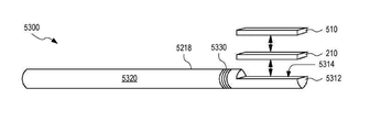
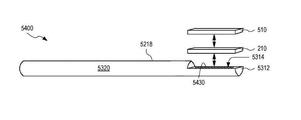
실시예에서, 고체 상태 냉각기능을 갖춘 향상된 초음파 치료용 시스템은 이전 단락에서 언급된 카테터, 및 2 개의 음향 미러를 포함한다. 2 개의 음향 미러 각각은 CMUT 어레이와 협력하여 각각의 음향 공동을 형성함으로써 음향 공동 내의 초음파 세기를 증가시키도록 구성된다.In an embodiment, an improved ultrasound therapy system with solid state cooling includes the catheter mentioned in the previous paragraph, and two acoustic mirrors. Each of the two acoustic mirrors is configured to increase the ultrasonic intensity within the acoustic cavity by forming each acoustic cavity in cooperation with the CMUT array.
실시예에서, 의료 장치는 표적 조직을 초음파에 노출시키기 위한 카테터를 포함한다. 카테터는 (a) 카테터의 원위 단부에 배치되고 초음파를 표적 조직으로 방출하도록 구성된 CMUT 어레이, (b) 초음파에 의해 가열된 비-표적 조직을 냉각하도록 구성된 열전 냉각기, (c) 열전 냉각기에 커플링되고 카테터를 따라 카테터의 원위 단부로부터 근위 단부 쪽으로 멀리 연장되어 열전 냉각기로부터 멀리 열을 전도시키는 고체 열 전도체를 포함한다. 의료 장치는 카테터의 근위 단부에 기계적으로 커플링되고 카테터가 내부에 삽입되는 신체 채널 외부에 위치되어 카테터를 적어도 부분적으로 제어하도록 구성된 카테터 핸들을 더 포함한다.In an embodiment, the medical device includes a catheter for exposing the target tissue to ultrasound. The catheter is (a) a CMUT array disposed at the distal end of the catheter and configured to emit ultrasound waves to the target tissue, (b) a thermoelectric cooler configured to cool non-target tissue heated by ultrasound, (c) coupling to a thermoelectric cooler And includes a solid heat conductor that runs along the catheter and extends away from the distal end of the catheter toward the proximal end to conduct heat away from the thermoelectric cooler. The medical device further comprises a catheter handle mechanically coupled to the proximal end of the catheter and positioned outside the body channel into which the catheter is inserted, configured to at least partially control the catheter.
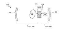
실시예에서, 향상된 초음파 치료용 시스템은 초음파 변환기 어레이를 포함하고 신체의 표적 조직을 초음파에 노출시키기 위해 초음파 변환기 어레이를 신체의 채널에 위치시키도록 구성된 카테터, 및 적어도 하나의 음향 미러를 포함한다. 각각의 음향 미러는 초음파 변환기 어레이의 반대편에 있는 표적 조직의 측면에서 채널의 외부에 위치하도록 구성되어, 초음파 변환기 어레이와 음향 미러 사이에 정재파(standing acoustic wave)를 생성함으로써 표적 조직에서 초음파의 세기를 향상시키는 음향 공동을 형성한다.In an embodiment, an improved ultrasound therapy system includes an array of ultrasound transducers and a catheter configured to position the array of ultrasound transducers in a channel of the body to expose target tissue of the body to ultrasound, and at least one acoustic mirror. Each acoustic mirror is configured to be located outside of the channel on the side of the target tissue opposite the array of ultrasound transducers, thereby generating a standing acoustic wave between the array of ultrasound transducers and the acoustic mirror to increase the intensity of the ultrasound in the target tissue. It forms an acoustic cavity to enhance.
실시예에서, 향상된 초음파 치료용 시스템은 제 1 초음파 변환기 어레이, 및 음향 공동을 형성하기 위해 제 1 초음파 변환기 어레이와 협력하도록 구성된 제 2 초음파 변환기 어레이를 포함하며, 음향 공동은 음향 공동 내에 정재파를 생성함으로써 표적 조직에서, 제 1 초음파 변환기 어레이 및 제 2 초음파 변환기 어레이에 의해 발생된 초음파의 세기를 향상시킨다.In an embodiment, the system for improved ultrasound treatment comprises a first ultrasound transducer array, and a second ultrasound transducer array configured to cooperate with the first ultrasound transducer array to form an acoustic cavity, the acoustic cavity generating standing waves within the acoustic cavity By doing so, in the target tissue, the intensity of ultrasonic waves generated by the first ultrasonic transducer array and the second ultrasonic transducer array is improved.
실시예에서, 고체 상태 냉각기능을 갖춘 카테터 또는 카테터 슬리브는 신체의 채널 내로 삽입하기 위한 관형 벽, 및 채널의 조직을 냉각시키기 위해 관형 벽에 커플링된 적어도 하나의 열전 냉각기를 포함한다.In an embodiment, a catheter or catheter sleeve with solid state cooling includes a tubular wall for insertion into a channel in the body, and at least one thermoelectric cooler coupled to the tubular wall to cool the tissue of the channel.
실시예에서, 통합된 감지기능을 갖춘 카테터 슬리브는 신체의 채널 내로 삽입되고 카테터를 감쌀 수 있는 관형 케이싱, 및 관형 케이싱에 커플링되고 채널의 조직의 하나 이상의 특성을 감지하도록 구성된 적어도 하나의 센서를 포함한다. 하나 이상의 특성 각각은 온도 및 압력으로 이루어진 그룹으로부터 선택된다.In an embodiment, a catheter sleeve with integrated sensing features a tubular casing that is inserted into a channel of the body and can wrap the catheter, and at least one sensor coupled to the tubular casing and configured to sense one or more characteristics of the tissue of the channel. Includes. Each of the one or more properties is selected from the group consisting of temperature and pressure.
실시예에서, 고체 상태 냉각기능을 갖춘 초음파 치료용 시스템은 표적 조직을 초음파에 노출시키기 위해 CMUT 어레이를 구동하기 위한 구동 신호를 발생하도록 구성된 초음파 구동 회로를 포함한다. 시스템은 초음파에 의해 가열된 비-표적 조직을 냉각시키기 위해 적어도 하나의 열전 냉각기를 구동하도록 구성된 펠티에 구동 회로(Peltier driving circuitry)를 더 포함한다.In an embodiment, a system for ultrasound therapy with solid state cooling includes an ultrasound drive circuit configured to generate a drive signal to drive the CMUT array to expose target tissue to ultrasound. The system further includes a Peltier driving circuitry configured to drive at least one thermoelectric cooler to cool the non-target tissue heated by ultrasound.
실시예에서, 고체 상태 냉각기능을 갖춘 초음파 치료 방법은 (a) CMUT 어레이에 의해 발생된 초음파에 표적 조직을 노출시키는 단계, (b) 하나 이상의 열전 냉각기를 사용하여 비-표적 조직을 냉각시켜 비-표적 조직의 손상을 방지하는 단계, 및 (c) 하나 이상의 열전 냉각기 및 비-표적 조직으로부터 멀리 열을 제거하는 단계를 포함한다.In an embodiment, an ultrasound treatment method with solid state cooling comprises (a) exposing the target tissue to ultrasound generated by the CMUT array, and (b) cooling the non-target tissue using one or more thermoelectric coolers. -Preventing damage to the target tissue, and (c) removing heat away from the one or more thermoelectric coolers and non-target tissue.
실시예에서, 초음파 이미징 피드백에 의한 초음파 치료 방법은 (a) 초음파 변환기 어레이로부터 표적 조직의 이미지를 얻어 표적 조직에 대해 공간적으로 분해된 클러터 신호(clutter signal)를 결정하는 단계, 및 (b) 클러터 신호 및 클러터 신호와 치료 효능 사이의 미리 결정된 대응관계에 기초하여, 표적 조직을 치료하기 위해 초음파 변환기 어레이에 의한 초음파의 후속 발생에 대한 하나 이상의 특성을 결정하는 단계를 포함한다.In an embodiment, an ultrasound treatment method using ultrasound imaging feedback comprises (a) obtaining an image of a target tissue from an array of ultrasound transducers to determine a spatially resolved clutter signal to the target tissue, and (b) Based on the clutter signal and a predetermined correspondence between the clutter signal and therapeutic efficacy, determining one or more properties for the subsequent occurrence of ultrasound by the array of ultrasound transducers to treat the target tissue.
실시예에서, 초음파 이미지 피드백을 사용하여 초음파 치료를 제어하기 위한 제품은 비-일시적 메모리에 인코딩된 기계 판독 가능한 명령어를 포함한다. 기계 판독 가능한 명령어는 (a) 초음파 클러터 신호와 초음파 치료 효능 사이의 대응관계, 및 (b) 프로세서에 의해 실행될 때, 표적 조직의 초음파 이미징으로부터 얻어진 공간적으로 분해된 클러터 신호를 평가하고 표적 조직의 후속 초음파 노출에 대한 하나 이상의 특성을 결정하기 위해 대응관계를 이용하는 치료 제어 명령어를 포함한다.In an embodiment, a product for controlling ultrasound therapy using ultrasound image feedback includes machine-readable instructions encoded in a non-transitory memory. Machine readable instructions evaluate (a) the relationship between the ultrasonic clutter signal and the efficacy of the ultrasound treatment, and (b) when executed by the processor, evaluate the spatially resolved clutter signal obtained from ultrasound imaging of the target tissue and target tissue And treatment control instructions that use the correspondence to determine one or more characteristics of the subsequent ultrasound exposure.
실시예에서, 고상 냉각기능을 갖춘 CMUT 어레이의 제작 방법은 열전 냉각기의 제 1 열 전도체에 CMUT 어레이를 제작하는 단계를 포함한다. 열전 냉각기는 (a) 제 1 열 전도체, (b) 제 2 열 전도체, 및 (c) 제 1 열 전도체와 제 2 열 전도체 사이에 배치되는 복수의 n-형 반도체 및 복수의 p-형 반도체를 포함하며, 복수의 n-형 반도체와 p-형 반도체는 전기적으로 직렬로 커플링되어 n-형 반도체와 p-형 반도체 사이에서 직렬 커플링이 교대한다.In an embodiment, a method of fabricating a CMUT array with solid phase cooling includes fabricating a CMUT array on a first thermal conductor of a thermoelectric cooler. The thermoelectric cooler comprises: (a) a first thermal conductor, (b) a second thermal conductor, and (c) a plurality of n-type semiconductors and a plurality of p-type semiconductors disposed between the first and second thermal conductors. And a plurality of n-type semiconductors and p-type semiconductors are electrically coupled in series such that the series coupling between the n-type semiconductor and the p-type semiconductor is alternating.
도 1은 실시예에 따라서 용량성 미세기계가공 초음파 변환기(CMUT) 어레이 및 고체 상태 냉각기능을 갖춘 의료 장치를 예시한다.
도 2는 실시예에 따라서 CMUT 어레이 및 적어도 하나의 열전 냉각기를 갖는 CMUT-열전 냉각기(TEC) 장치를 예시한다.
도 3은 예시적인 사용 시나리오에서 그리고 표적 조직을 치료하기 위해 신체 채널에 배치되는 도 2의 CMUT-TEC 장치를 예시한다.
도 4는 실시예에 따라서 CMUT 어레이를 통해 하나 이상의 열전 냉각기를 비-표적 조직에 열적으로 커플링하는 CMUT-TEC 장치를 예시한다.
도 5는 실시예에 따라서 CMUT 어레이를 통해 하나 이상의 열전 냉각기를 비-표적 조직에 열적으로 커플링하는 다른 CMUT-TEC 장치를 예시한다.
도 6은 CMUT-TEC 장치가 신체 채널의 벽과 물리적으로 접촉하도록 크기가 정해지는 예시적인 사용 시나리오에서 도 4 및 도 5의 CMUT-TEC 장치의 예시적인 실시예를 예시한다.
도 7은 실시예에 따라서 CMUT-TEC 장치 및 CMUT-TEC 장치로부터 멀리 열을 전도하기 위한 고체 열 전도체를 포함하는 의료 장치를 예시한다.
도 8은 실시예에 따른 1 차원 CMUT 어레이를 예시한다.
도 9는 실시예에 따른 1.5D CMUT 어레이를 예시한다.
도 10은 실시예에 따른 1.75D CMUT 어레이를 예시한다.
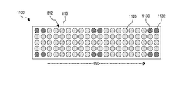
도 11은 실시예에 따른 2 차원 CMUT 어레이를 예시한다.
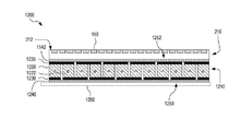
도 12a 및 도 12b는 각각, 실시예에 따른 CMUT-TEC 장치의 단면도 및 평면도를 예시한다.
도 13은 실시예에 따라서 그 사이에 조정 가능한 각도를 갖는 2 개의 평면 CMUT 서브어레이를 갖춘 CMUT-TEC 장치를 예시한다.
도 14는 실시예에 따라서 그 사이에 조정 가능한 각도를 갖는 2 개의 평면 CMUT 서브어레이를 갖는 CMUT-TEC 장치를 예시한다.
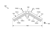
도 15는 실시예에 따라서 서로로부터 멀어지게 경사진 2 개의 평면 CMUT 서브어레이를 갖춘 CMUT-TEC 장치를 예시한다.
도 16은 실시예에 따라서 서로로부터 멀어지게 경사진 2 개의 평면 CMUT 서브어레이를 갖춘 CMUT-TEC 장치를 예시한다.
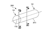
도 17은 실시예에 따른 CMUT-TEC 변환기 장치를 갖춘 카테터를 예시한다.
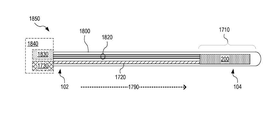
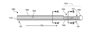
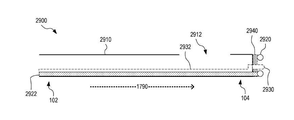
도 18은 실시예에 따른 CMUT-TEC 장치를 갖춘 다른 카테터를 예시한다.
도 19, 도 20 및 도 21은 실시예에 따른 CMUT-TEC 장치를 갖춘 카테터를 예시한다.
도 22는 실시예에 따라서 제거 가능한 방식으로 CMUT 어레이 및 고체 상태 냉각기능을 갖춘 카테터를 감싸도록 구성된 카테터 슬리브를 예시한다.
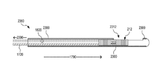
도 23은 실시예에 따라서 CMUT-TEC 장치의 제거를 허용하는 관형 카테터 재킷을 사용하는 CMUT-TEC 장치를 갖춘 카테터를 예시한다.
도 24는 실시예에 따른 고체 상태 냉각기능을 갖춘 카테터 또는 카테터 슬리브를 예시한다.
도 25는 실시예에 따라서 그의 관형 벽에 커플링된 적어도 하나의 열전 냉각기를 갖는 카테터 또는 카테터 슬리브를 예시한다.
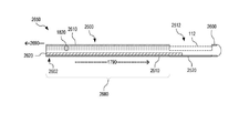
도 26은 실시예에 따라서 적어도 하나의 열전 냉각기 및 그의 관형 벽에 커플링된 고체 열 전도체를 가지는 카테터 또는 카테터 슬리브를 예시한다.
도 27a 및 도 27b는 실시예에 따른 열전 냉각기능을 갖춘 카테터 또는 카테터 슬리브를 예시한다.
도 28a 내지 도 28d는 실시예에 따른 열전 냉각기능을 갖춘 다른 카테터 또는 카테터 슬리브를 예시한다.
도 29는 실시예에 따라서 신체 채널의 일부분에 고정되는 동안 신체 채널 내부로부터 표적 조직의 초음파 치료를 위한 카테터를 감싸도록 구성된 카테터 슬리브를 예시한다.
도 30은 실시예에 따라서 방광에 고정되는 동안 요도 내부로부터 전립선의 초음파 치료를 위한 요도 카테터를 감싸도록 구성된 요도 카테터 슬리브를 예시한다.
도 31은 실시예에 따라서 신체 채널 내에 하나 이상의 통합 센서를 갖춘 카테터 슬리브를 예시한다.
도 32는 실시예에 따라서 그의 관형 케이싱에 하나 이상의 하드와이어 센서를 갖는 카테터 슬리브를 예시한다.
도 33은 실시예에 따라서 그의 관형 케이싱에 하나 이상의 무선 통신 기반 센서를 갖는 카테터 슬리브를 예시하며, 여기서 각각의 센서는 카테터 슬리브 내에 삽입된 카테터에 의해 판독된다.
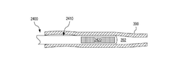
도 34는 실시예에 따라서 그의 관형 케이싱에 적어도 하나의 센서를 갖는 카테터 슬리브를 예시하며, 여기서 각각의 센서는 카테터 슬리브에 삽입되고 센서와 전기 접촉되게 배치된 카테터에 의해 판독되도록 구성된다.
도 35는 실시예에 따른 초음파 치료 및 고체 상태 냉각기능을 위한 시스템을 예시한다.
도 36은 실시예에 따른 CMUT 어레이 및 고체 상태 냉각기능을 갖춘 의료 장치를 예시한다.
도 37은 실시예에 따른 CMUT 어레이, 고체 상태 냉각기능 및 관련 고체 상태 열 제거기능을 갖춘 의료 장치를 예시한다.
도 38은 실시예에 따라서 신체 채널에 고정되도록 구성된 카테터 슬리브를 포함한, CMUT 어레이 및 고체 상태 냉각기능을 갖는 의료 시스템을 예시한다.
도 39는 실시예에 따른 초음파 치료를 제어하기 위한 컴퓨터를 예시한다.
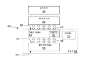
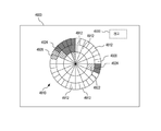
도 40은 실시예에 따른 향상된 초음파 치료 시스템을 예시한다.
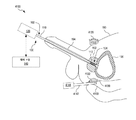
도 41은 실시예에 따른 요도의 고체 상태 냉각기능으로 전립선의 향상된 초음파 치료를 위한 시스템을 예시한다.
도 42는 실시예에 따른 향상된 초음파 치료를 위한 다른 시스템을 예시한다.
도 43은 실시예에 따라서 요도의 고체 상태 냉각기능으로 전립선의 향상된 초음파 치료를 위한 다른 시스템을 예시한다.
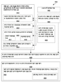
도 44는 실시예에 따라서 고체 상태 냉각기능으로 초음파 치료를 위한 방법을 예시한다.
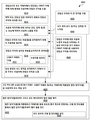
도 45는 실시예에 따라서 요도의 고체 상태 냉각기능으로 전립선의 초음파 치료를 위한 방법을 예시한다.
도 46은 실시예에 따라서 초음파 이미징 피드백으로 초음파 치료를 위한 방법을 예시한다.
도 47은 실시예에 따라서 초음파 이미지 피드백으로 초음파 치료를 제어하기 위한 시스템을 예시한다.
도 48은 실시예에 따라서 고체 상태 냉각기능으로 표적 조직의 초음파 치료를 위한 프로토콜을 예시한다.
도 49는 실시예에 따라서 CMUT 어레이의 여러 상이한 위치/방위를 요구하는 정도로 표적 조직의 치료를 관리하기 위해 도 48의 프로토콜과 함께 이용되도록 구성된 그래픽 사용자 인터페이스를 예시한다.
도 50은 실시예에 따라서 고체 상태 냉각기능을 갖춘 CMUT 어레이를 제작하는 방법을 예시한다.
도 51은 실시예에 따른 수동 냉각(passive cooling)기능을 갖춘 의료 CMUT 장치를 예시한다.
도 52 내지 도 54는 도 51의 CMUT 장치의 상이한 예시적인 구성을 도시한다.
도 55는 실시예에 따른 수동 냉각기능으로 초음파 치료를 위한 시스템을 예시한다.
도 56은 실시예에 따른 수동 냉각기능을 으로 초음파 치료를 위한 방법을 예시한다.
도 57은 실시예에 따라서 요도의 수동 냉각기능으로 전립선의 초음파 치료를 위한 방법을 예시한다.1 illustrates a capacitive micromachining ultrasound transducer (CMUT) array and a medical device with solid state cooling according to an embodiment.
2 illustrates a CMUT-thermoelectric cooler (TEC) device having a CMUT array and at least one thermoelectric cooler according to an embodiment.
FIG. 3 illustrates the CMUT-TEC device of FIG. 2 deployed in a body channel in an exemplary use scenario and to treat target tissue.
4 illustrates a CMUT-TEC device that thermally couples one or more thermoelectric coolers to a non-target tissue through a CMUT array according to an embodiment.
5 illustrates another CMUT-TEC device that thermally couples one or more thermoelectric coolers to a non-target tissue through a CMUT array according to an embodiment.
6 illustrates an exemplary embodiment of the CMUT-TEC device of FIGS. 4 and 5 in an exemplary use scenario where the CMUT-TEC device is sized to physically contact the wall of the body channel.
7 illustrates a medical device comprising a CMUT-TEC device and a solid heat conductor for conducting heat away from the CMUT-TEC device, according to an embodiment.
8 illustrates a one-dimensional CMUT array according to an embodiment.
9 illustrates a 1.5D CMUT array according to an embodiment.
10 illustrates a 1.75D CMUT array according to an embodiment.
11 illustrates a two-dimensional CMUT array according to an embodiment.
12A and 12B respectively illustrate a cross-sectional view and a top view of a CMUT-TEC device according to an embodiment.
13 illustrates a CMUT-TEC device with two planar CMUT subarrays with adjustable angles in between according to embodiments.
14 illustrates a CMUT-TEC device with two planar CMUT subarrays with an adjustable angle therebetween, according to an embodiment.
15 illustrates a CMUT-TEC device with two planar CMUT subarrays inclined away from each other according to an embodiment.
FIG. 16 illustrates a CMUT-TEC device with two planar CMUT subarrays inclined away from each other according to an embodiment.
17 illustrates a catheter with a CMUT-TEC converter device according to an embodiment.
18 illustrates another catheter with a CMUT-TEC device according to an embodiment.
19, 20 and 21 illustrate a catheter with a CMUT-TEC device according to an embodiment.
22 illustrates a catheter sleeve configured to enclose a CMUT array and a catheter with solid state cooling in a removable manner according to an embodiment.
23 illustrates a catheter with a CMUT-TEC device using a tubular catheter jacket allowing removal of the CMUT-TEC device according to an embodiment.
24 illustrates a catheter or catheter sleeve with solid state cooling according to an embodiment.
25 illustrates a catheter or catheter sleeve with at least one thermoelectric cooler coupled to its tubular wall according to an embodiment.
26 illustrates a catheter or catheter sleeve having a solid thermal conductor coupled to at least one thermoelectric cooler and its tubular wall, according to an embodiment.
27A and 27B illustrate a catheter or catheter sleeve with thermoelectric cooling according to an embodiment.
28A-28D illustrate another catheter or catheter sleeve with thermoelectric cooling according to an embodiment.
29 illustrates a catheter sleeve configured to wrap a catheter for ultrasound treatment of target tissue from inside the body channel while being secured to a portion of the body channel according to an embodiment.
30 illustrates a urethral catheter sleeve configured to enclose a urethral catheter for ultrasound treatment of the prostate from inside the urethra while secured to the bladder according to an embodiment.
31 illustrates a catheter sleeve with one or more integrated sensors in the body channel, according to an embodiment.
32 illustrates a catheter sleeve with one or more hardwire sensors in its tubular casing according to an embodiment.
33 illustrates a catheter sleeve with one or more wireless communication based sensors in its tubular casing according to an embodiment, where each sensor is read by a catheter inserted into the catheter sleeve.
34 illustrates a catheter sleeve with at least one sensor in its tubular casing according to an embodiment, wherein each sensor is configured to be read by a catheter inserted into the catheter sleeve and placed in electrical contact with the sensor.
35 illustrates a system for ultrasound therapy and solid state cooling according to an embodiment.
36 illustrates a medical device with a CMUT array and solid state cooling according to an embodiment.
37 illustrates a medical device with a CMUT array, solid state cooling and associated solid state heat removal according to an embodiment.
38 illustrates a medical system with a CMUT array and solid state cooling, including a catheter sleeve configured to be secured to a body channel according to an embodiment.
39 illustrates a computer for controlling ultrasound therapy according to an embodiment.
40 illustrates an improved ultrasound therapy system according to an embodiment.
41 illustrates a system for improved ultrasound treatment of the prostate with solid state cooling of the urethra according to an embodiment.
42 illustrates another system for improved ultrasound treatment according to an embodiment.
43 illustrates another system for improved ultrasound treatment of the prostate with solid state cooling of the urethra, according to an embodiment.
44 illustrates a method for ultrasound therapy with a solid state cooling function according to an embodiment.
45 illustrates a method for ultrasound treatment of the prostate with a solid state cooling function of the urethra according to an embodiment.
46 illustrates a method for ultrasound therapy with ultrasound imaging feedback according to an embodiment.
47 illustrates a system for controlling ultrasound therapy with ultrasound image feedback according to an embodiment.
48 illustrates a protocol for ultrasound treatment of target tissue with solid state cooling according to an embodiment.
FIG. 49 illustrates a graphical user interface configured to be used with the protocol of FIG. 48 to manage treatment of target tissue to the extent that it requires several different locations / orientations of the CMUT array according to an embodiment.
50 illustrates a method of manufacturing a CMUT array with solid state cooling according to an embodiment.
FIG. 51 illustrates a medical CMUT device with passive cooling according to an embodiment.
52-54 show different exemplary configurations of the CMUT device of FIG. 51.
55 illustrates a system for ultrasound treatment with a passive cooling function according to an embodiment.
56 illustrates a method for ultrasound therapy with a manual cooling function according to an embodiment.
57 illustrates a method for ultrasound treatment of the prostate with manual cooling of the urethra according to an embodiment.
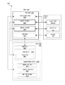
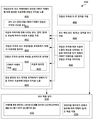
도 1은 용량성 미세기계가공 초음파 변환기(CMUT) 어레이 및 고체 상태 냉각기능을 갖춘 하나의 의료 장치(100)를 예시한다. 장치(100)는 신체 공동(body cavity), 덕트(duct) 또는 용기로부터 신체 조직을 치료하도록 구성되고; 본 명세서에서 총칭하여 "신체 채널(body channel)"로 지칭된다.FIG. 1 illustrates a capacitive micromachining ultrasound transducer (CMUT) array and one
도 1의 실시예에서, 의료 장치(100)는 요도(194)와 같은 신체 채널 내로 삽입되도록 구성된 카테터(110)를 포함한다. 의료 장치(100)는 카테터(110)의 근위 단부(102)에 기계적으로 커플링되고 카테터(110)를 적어도 부분적으로 제어하기 위해 신체 채널 외부에 위치되도록 구성되는 핸들(120)을 더 포함한다. 카테터(110)는 그의 원위 단부(104)에 또는 그 근처에, CMUT 어레이(112) 및 고체 상태 냉각기능을 제공하는 적어도 하나의 열전 냉각기(TEC)(114)를 갖는 CMUT-열전 냉각기 장치(116)를 포함한다. 카테터(110)를 조절함으로써, CMUT-TEC 장치(116)는 초음파로 치료될 대상자(190)의 표적 조직의 작업 거리 내에 위치될 수 있다.In the embodiment of FIG. 1,
작동시, CMUT 어레이(112)는 전립선(192)과 같은 표적 조직에 초음파를 방출하여, 예를 들어 표적 조직의 괴사를 유도하고, 열전 냉각기(114)는 초음파에 의해 가열되는 비-표적 조직을 냉각시켜 비-표적 조직에 대한 열-유도 손상을 방지한다. 비-표적 조직은 초음파에 대한 직접 노출에 의해 및/또는 표적 조직 또는 초음파에 노출된 다른 조직으로부터 비-표적 조직으로의 열 전파에 의해 가열될 수 있다.In operation, the
도 1은 하나의 예시적인 시나리오에서, 요도로부터 전립선 또는 전립선의 일부를 초음파에 노출시키기 위한 의료 장치(100)를 도시한다. 이러한 예시적인 시나리오에서, 의료 장치(100)는 예를 들어, 방광(196)으로부터 소변의 흐름을 개선하기 위해 양성 전립선 비대증(BPH)을 치료할 수 있거나; 장치(100)는 전립선 암을 치료할 수 있다. 의료 장치(100)의 특정 실시예는 BPH 및 전립선 암의 조합을 치료할 수 있다. 이들 상태 중 어느 것이 치료될지에 관계없이, CMUT 어레이(112)는 전립선 조직에 초음파를 방출하도록 작동할 수 있는 반면에, 열전 냉각기(114)는 요도에 대한 열-유도 손상을 방지하기 위해 요도 벽의 적어도 일부분을 냉각시킨다. 그러나, 본 발명의 범주로부터 벗어남이 없이, 의료 장치(100)는 다른 시나리오에서, 요도와 상이한 신체 채널로부터 다른 유형의 신체 조직을 치료하기 위해 사용될 수 있다.1 shows a
CMUT 어레이(112)는 CMUT 셀(150)의 어레이를 포함한다. 일 실시예에서, CMUT 셀(150)은 CMUT 요소의 어레이로 구성된다. 각각의 CMUT 요소는 단일의 더 큰 CMUT 셀로서 협력하여 기능을 하기 위해 일체로 구동되도록 구성된 복수의 CMUT 셀(150)을 포함한다. 도 1은 CMUT 셀(150)의 하나의 예시적인 실시예를 개략적으로 예시한다. 이러한 실시예에서, 각각의 CMUT 셀(150)은 기판(180), 내부에 형성된 공동(172)을 갖는 전기 절연 층(170), 상부에 배치된 전극(162)을 갖춘 막(160), 및 선택적으로 전극(162)과 막(160) 위에 배치된 보호/전기 절연 층(164)을 포함한다. 함께, 층(170)과 막(160)은 공동(172) 내에 진공을 함유할 수 있거나; 층(170)과 막(160)은 공동(172) 내에 대기압 미만의 가스를 함유할 수 있다. 적절한 주파수의 시변 전압 강하가 바닥 전극으로서 기능을 하는 전극(162)과 기판(180) 사이에 인가될 때, 전극(162)과 기판(180) 사이의 결과적인 전계는 막(160)이 진동하여 초음파를 발생하게 할 것이다. 특정 실시예에서, 기판(180)은 실리콘 기판이고, 전기 절연 층(170)과 막(160) 각각은 실리콘-계이다. 대안적으로, 막(160)은 나노 튜브-기반 막일 수 있다. 본 발명의 범주를 벗어남이 없이, CMUT 셀(150)은 상이한 구성일 수 있다. 예를 들어, CMUT 셀(150)은 추가 층을 포함할 수 있고/있거나 공동(172)이 공동(172)의 바닥에 배치된 전극을 갖춘 유리 기판 내에 형성될 수 있다.The
CMUT 셀(150)은 조금이라도 있다면, 매우 적은 열을 발생시킨다. 대조적으로, 전형적인 압전 변환기에 전달된 전기 에너지의 약 40 %는 (압전 변환기의 유전 상수의 가상 부분에 의해 지시된 바와 같이)압전 재료에서 마찰로 손실되고, 따라서 압전 변환기 자체에서 상당한 양의 열을 발생시킨다. 결과적으로, 압전 변환기를 사용하여 압전 변환기로부터 떨어진 거리에 표적 조직(예를 들어, 전립선 조직)을 가열할 때, 압전 변환기에서 발생된 열은 일반적으로 초음파에서 유도된 열보다 크거나 크지 않다. 따라서, 압전 변환기 근처의 조직이 표적 조직의 일부가 아니고, 이 조직의 가열에 의해 바람직하지 않은 손상이 초래되면, 압전 변환기 및/또는 인접한 조직을 냉각시키기 위해 압전 변환기의 위치에서 상당한 냉각이 적용되어야 한다. 압전 변환기를 사용하여 전립선의 초음파 치료를 목적으로 하는 요도 카테터의 경우에, 압전 변환기 및/또는 압전 변환기 근처의 요도 벽의 액체 냉각은 요도 벽의 손상을 방지하기 위해 초음파 처리를 수반해야 한다. 결과적으로, 그러한 카테터에는 요도 카테터를 통해 차가운 액체를 압전 변환기의 부위로 운반하는 냉각 유체 회로가 장착되어야 하며, 여기서 차가운 액체는 카테터를 통해 요도 밖으로 다시 전달되기 전에 일부 열을 흡수할 수 있다. 그러한 냉각 유체 회로는 카테터에 복잡성과 부피를 증가시키고, 외부 액체를 환자에게 도입하는 것과 관련된 안전 규제 요건과 또한 관련된다. 유리하게, CMUT 셀(150)의 무시할만한 열 발생으로 인해 현재 개시된 초음파 변환기(116)는 훨씬 낮은 냉각 용량으로 안전하게 작동할 수 있다. 열전 냉각기(114)에 의해 제공되는 바와 같은 고체 상태 냉각이면 충분하다. 고체 상태 냉각은 높은 정도의 온도 제어를 제공한다. 열전 냉각기에 의해 제공된 냉각이 펠티어(Peltier) 효과에 의해 관리되기 때문에, 열전 냉각기가 즉시 켜지고 꺼질 수 있고 냉각 정도가 쉽게 조절될 수 있다. 대조적으로, 열 저장소와의 수동 열 교환에 기초한 냉각, 예를 들어 수냉 또는 다른 액체 냉각은 냉각제의 열 질량으로 인한 저속 온/오프 전이와 관련된다. 따라서, 열전 냉각기(114)의 작동은 CMUT 어레이(112)에 의한 초음파 처리 동안 필요에 따라 쉽고 빠르게 조절될 수 있다. 예를 들어, 과냉각을 방지하거나 보상하기 위해 필요하다면, 비-표적 조직을 가열하기 위해 열전 냉각기(114)를 역으로 구동하는 것도 심지어 가능하다.The
도 1의 실시예에서, 의료 장치(100)는 초음파 치료 시스템(130)의 제어 모듈(140)과 통신 가능하게 커플링되며, 핸들(120)은 CMUT 어레이(112) 및 열전 냉각기(114)의 작동과 관련된 전자 회로를 포함한다. 제어 모듈(140)은 치료 절차에 따라 CMUT 어레이(112) 및 열전 냉각기(114)를 작동시키도록 핸들(120)의 전자 회로를 제어한다. 본 발명의 범주를 벗어남이 없이, 핸들(120)의 전자 회로는 대신에, 핸들(120) 외부의 제어 모듈(140)과 또는 제어 모듈(140)에 통합되거나, 제어 모듈(140)은 핸들(120)의 전자 회로와 함께 핸들(120)로 구현될 수 있다.In the embodiment of FIG. 1, the
표적 조직(예를 들어, 전립선(192))을 치료하기 위해 초음파를 발생하는 것 이외에, CMUT 어레이(112)는 표적 조직(또는 CMUT 어레이(112)의 시야에 있는 다른 조직)의 초음파 이미징을 수행할 수 있다. 일 예에서, 제어 모듈(140)은 CMUT 어레이(112)에 의해 기록된 표적 조직의 초음파 이미지를 이용하여 표적 조직의 초음파 치료의 진행을 평가하고 이러한 평가에 따라 CMUT 어레이(112)에 의한 표적 조직의 초음파 노출을 조정한다. 치료 프로토콜의 일 예에서, 제어 모듈(140)은 CMUT 어레이(112)에게 (a) 표적 조직을 가열하기 위해 높은 에너지 레벨에서 초음파를 방출하는 것과 (b) 더 낮은 에너지 레벨에서 초음파를 방출하고 조직에 의해 CMUT 어레이(112)로 다시 반사된 초음파를 검출함으로써 표적 조직(및/또는 CMUT 어레이(112)의 시야에 있는 다른 조직)을 이미지화하는 것 사이에서 교대하도록 명령한다.In addition to generating ultrasound to treat target tissue (eg, prostate 192),
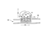
도 2는 CMUT 어레이(210) 및 적어도 하나의 열전 냉각기(220)를 갖는 하나의 CMUT-TEC 장치(200)를 예시한다. CMUT-TEC 장치(200)는 예를 들어, 도 1의 초음파 변환기(116)의 실시예이다. 대안적으로, CMUT-TEC 장치(200)는 다른 카테터에 전개될 수 있다. 또는, CMUT-TEC 장치(200)는 예를 들어, 환자의 피부 또는 수술로 노출된 표면에 배치하기 위해 카테터없이 작동하도록 구성될 수 있다.2 illustrates one CMUT-
CMUT 어레이(210)는 초음파 방출 면(212)으로부터 표적 조직(280)으로 초음파(270)를 방출하도록 구성된 CMUT(150)의 어레이를 포함한다. 열전 냉각기(220)는 초음파(270)에 의해 직접적으로 또는 간접적으로 가열된 비-표적 조직(290)을 펠티어 효과에 의해 냉각시키도록 구성된다.The
특정 실시예에서, CMUT-TEC 장치(200)는 비-표적 조직(290) 및/또는 표적 조직(280)의 하나 이상의 특성을 감지하는 하나 이상의 센서(230)를 포함한다. 센서(230)는 예를 들어, 온도, 압력 또는 둘 모두를 감지할 수 있다. 각각의 센서(230)는 예를 들어, 고체 상태 온도 센서 또는 고체 상태 압력 센서와 같은 고체 상태 센서이다.In certain embodiments, the CMUT-
따라서, 센서(들)(230)는 비-표적 조직(290)에 대한 초음파(270)의 직접 또는 간접 효과를 나타내는 하나 이상의 특성을 감지할 수 있다. 예를 들어, 조작자 또는 자동 제어기는 비-표적 조직(290)의 특성이 허용 가능한 범위, 예컨대 임계 온도를 초과하는 온도 또는 임계 압력을 초과하는 압력 밖에 있음을 센서(들)(230)가 감지할 때 CMUT 어레이(210)에 의해 초음파(270)의 방출을 적어도 일시적으로 중단, 감소 또는 재지향시킬 수 있다. 요도(194)로부터 전립선(192)의 초음파 치료와 관련된 하나의 사용 시나리오에서, 임계 온도는 요도(194)에 대한 손상을 방지하기 위해 41 ℃ 내지 45 ℃의 범위 내, 예컨대 42 ℃이다. 표적 조직(280) 및 잠재적으로 또한 비-표적 조직(290)의 가열은 조직의 팽창을 유발할 수 있다. 조작자 또는 자동 제어기는 센서(들)(230)가 임계 압력을 초과하는 압력을 감지할 때 CMUT 어레이(210)에 의해 초음파(270)의 방출을 적어도 일시적으로 중단, 감소 또는 재지향시킬 수 있어서, 팽창 정도를 특정 수준 아래로 유지한다. 조작자 또는 자동 제어기는 또한, 센서(들)(230)에 의해 제공된 온도 측정에 기초하여 열전 냉각기(114)의 작동을 조정할 수 있다.Thus, the sensor (s) 230 can sense one or more characteristics that indicate the direct or indirect effect of
다른 실시예에서, 센서(들)(230)는 초음파(270)에 의한 표적 조직(280)의 치료 진행을 나타내는 하나 이상의 특성을 감지한다. 예를 들어, 센서(들)(230)는 표적 온도와 표적 조직(280)의 측정된 온도 사이의 차이의 평가를 용이하게 하기 위해 표적 조직(280)의 온도를 감지 할 수 있고; 센서(들)(230)는 열 모델을 사용하여 표적 조직(280)으로의 역전파와 함께 이러한 측정된 온도로부터 표적 조직(280)의 적어도 대략적인 온도의 추론을 용이하게 하기 위해 비-표적 조직(290)의 온도를 감지할 수 있고/있거나; 센서(들)(230)는 표적 조직(280) 및/또는 비-표적 조직(290)의 압력을 감지하여 조직의 열-유도 팽창에 대해 공지된 특성과 함께 측정된 압력으로부터 표적 조직(280)의 가열의 평가를 용이하게 할 수 있다. 하나의 사용 시나리오에서, 센서(들)(230)에 의해 수행된 측정에 기초하여 얻어진 정보는 초음파 이미지로부터 얻어진 정보와 조합되어 표적 조직(280)의 괴사, 온도 및/또는 부피와 같은 표적 조직(280)의 특성을 결정한다. 초음파 이미지는 CMUT 어레이(210)를 사용하여 얻어질 수 있다.In another embodiment, the sensor (s) 230 senses one or more characteristics that indicate the progress of treatment of the
도 2는 CMUT 어레이(210), 열전 냉각기(220) 및 포함될 때, 센서(들)(230)를 유지하는 고정구(260)를 도시한다. 고정구(260)는 예를 들어, 카테터 재킷(jacket)이다. 고정구(260)는 적어도 부분적으로 초음파(270)를 전송하는 CMUT 어레이(210) 위에 위치한 윈도우(window)를 포함할 수 있다.FIG. 2 shows the
열전 냉각기(들)(220)는 (a) 비-표적 조직(290)과 직접적인 열 연결되어 있거나, (b) 고정구(260)를 통해 비-표적 조직(290)과 간접적인 열 연결되어 있거나, (c) CMUT 어레이(210) 및 선택적으로 고정구(260)를 통한 비-표적 조직(290)과 간접적인 열 연결될 수 있다. 바람직하게, 각각의 열전 냉각기(220)는 CMUT 어레이(210)로부터 표적 조직(280)으로 초음파(270)의 전파 영역 외부에 위치된다. 센서(230)는 예를 들어, 고정구(260) 및/또는 CMUT 어레이(210)에 위치된다.The thermoelectric cooler (s) 220 may be either (a) in direct thermal connection with
도 2에 도시되지 않지만, CMUT-TEC 장치(200)는 CMUT 어레이(210) 및 각각의 열전 냉각기(220)(및 선택적으로 또한 각각의 센서(230))를 CMUT-TEC 장치(200) 외부에 위치된 외부 전자 회로에 연결하는 전기 연결부를 구비할 수 있음을 이해해야 한다. CMUT-TEC 장치(200)가 카테터(110)에 구현될 때, CMUT-TEC 장치(200)와 외부 전자 회로 사이의 전기적 연결은 카테터(110)를 통해 핸들(120)로 진행할 수 있다. 일 예에서, 외부 전자 회로는 CMUT 어레이(210) 및 각각의 열전 냉각기(220)(및 선택적으로 각각의 센서(230))를 구동하고, 또한 CMUT 어레이(210)로부터 초음파 이미징 신호 및/또는 센서(들)(230)로부터 센서 신호를 수신할 수 있다. 대안적으로, 전자 회로의 일부분은 CMUT-TEC 장치(200)에 위치된다.Although not shown in FIG. 2, the CMUT-
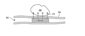
도 3은 예시적인 사용 시나리오에서 CMUT-TEC 장치(200)를 예시하며, 여기서 CMUT-TEC 장치(200)는 표적 조직(380)을 치료하기 위해 신체 채널(392)에 위치된다. 신체 채널(392)은 벽(390)을 가진다. CMUT 어레이(210)는 표적 조직(380)에 초음파(270)를 방출한다. 초음파(270)는 표적 조직(380)에서 열(370)로 적어도 부분적으로 변환된다. 열(370)의 일부분은 인접한 비-표적 조직으로 확산할 수 있다. 또한, CMUT-TEC 장치(200)와 벽(390)과 같은 표적 조직(380) 사이의 비-표적 조직은 초음파(270)에 직접 노출되어 이러한 비-표적 조직에서 일부 양의 열(370)을 직접 발생시킨다. 열전 냉각기(들)(220)는 벽(390)에 대한 열-유도 손상을 방지하기 위해 벽(390)의 적어도 일부분을 냉각시킨다.3 illustrates the CMUT-
도 4는 CMUT 어레이(210)를 통해 열전 냉각기(들)(220)를 비-표적 조직(290)에 열적으로 커플링하는 하나의 CMUT-TEC 장치(400)를 예시한다. CMUT-TEC 장치(400)는 도 2의 CMUT-TEC 장치(200)의 실시예이다. 열전 냉각기(들)(220)는 CMUT 어레이(210)와 직접 또는 간접적인 열 커플링(480) 상태에 있으며, 이는 표적 조직(280)으로 초음파(270)를 방출하도록 위치될 때 비-표적 조직(290)과 열 커플 링(470) 상태에 있다. CMUT 어레이(210)는 비-표적 조직(290)과 직접적인 열 커플 링(470) 상태에 있거나, 고정구(260)를 통해 비-표적 조직(290)과 간접적인 열 커플링(470) 상태에 있을 수 있다. 일 실시예에서, CMUT 어레이(210)의 초음파 방출 면(212)은 비-표적 조직(290)과 열 커플링(470) 상태에 있고, 열전 냉각기(들)(230)는 초음파 방출 면(212)에 대향하는 CMUT 어레이(210)의 측면과 열 커플링(480) 상태에 있다. 따라서, CMUT 어레이(210)는 열전 냉각기(들)(230)와 비-표적 조직(290) 사이에 열 경로를 제공한다.FIG. 4 illustrates one CMUT-
작동시, 전압 강하가 열전 냉각기(들)(220)에 인가되어 펠티어 효과를 통해 고온 측(424)과 저온 측(422)을 생성한다. 전압 강하의 방향은 각각의 열전 냉각기(220)의 저온 측(422)이 비-표적 조직(290)과 열 커플링(470) 상태에 있는 CMUT 어레이(210)와 열 커플링(480) 상태에 있다.In operation, a voltage drop is applied to the thermoelectric cooler (s) 220 to create a
도 5는 CMUT 어레이(210)를 통해 비-표적 조직(290)에 열전 냉각기(220)를 열적으로 커플링하여, 열전 냉각기(들)(220)가 CMUT 어레이(210)를 통과하는 열 경로를 통해 비-표적 조직(290)을 냉각시키도록 구성된 다른 CMUT-TEC 장치(500)를 예시한다. CMUT-TEC 장치(500)는 도 4의 CMUT-TEC 장치(400)의 실시예이다. CMUT-TEC 장치(500)는 CMUT 어레이(210)의 초음파 방출 면(212)에 커플링된 렌즈(510)를 포함한다. 렌즈(510)는 예를 들어, 표적 조직(280)에 초음파(270)를 포커싱한다. 일 실시예에서, CMUT-TEC 장치(500)는 연장되고 도 1의 카테터(110)와 같은 카테터에서 구현하도록 구성되며, 여기서 연장된 치수(도 3의 연장된 치수(340) 참조)는 카테터의 종축과 정렬된다. 이러한 실시예에서, 렌즈(510)는 상승 방향(도 3의 상승 방향(350) 참조)에서 특정 거리에 초음파(270)를 포커싱하며; 즉, 렌즈(510)는 CMUT-TEC 장치(500)의 연장된 치수(340)에 수직인 방향을 따라 초음파(270)의 방출을 조작한다. 작동시, 렌즈(510)는 선택적으로 고정구(260)를 통해 비-표적 조직(290)과 물리적으로 접촉하고, 따라서 CMUT 어레이(210)와 비-표적 조직(290) 사이에 열 커플링을 제공한다. 렌즈(510)는 열전 냉각기(들)(220)와 비-표적 조직(290) 사이의 열 경로의 일부를 형성한다. 도 5에 도시된 실시예에서, 열전 냉각기(들)(220)는 초음파 방출 면(212)과 반대인 CMUT 어레이(210)의 측면에 장착되거나 그와 공동으로 제작된다. 그러나, 본 발명의 범주를 벗어남이 없이, 열전 냉각기(들)(220)는 (a) CMUT 어레이(210)의 다른 측면, (b) 고정구(260), 또는 (c) CMUT-TEC 장치(500)가 구현되는 카테터의 튜브에 장착되거나 그와 함께 제작될 수 있다.5 thermally couples the
일 실시예에서, 열전 냉각기(들)(220)는 열 접착제에 의해 CMUT 어레이(210)에 접합된다. 다른 실시예에서, 열전 냉각기(들)(220)는 CMUT 어레이(210)에 접촉 접합된다. 또 다른 실시예에서, 고정구(260)는 CMUT 어레이(210)와 물리적으로 접촉하게 열전 냉각기(220)를 유지한다. 본 발명의 범주를 벗어남이 없이, 중간 기판(예를 들어, CMUT 어레이(210)와 열전 냉각기(들)(220) 중 하나 또는 둘 모두를위한 전기 연결을 포함함)은 CMUT 어레이(210)와 열전 냉각기(들)(220) 사이에 위치될 수 있다. 다른 실시예에서, CMUT 어레이(210)는 열전 냉각기(들)(220)에 직접적으로 제작된다.In one embodiment, thermoelectric cooler (s) 220 is bonded to the
렌즈(510)는 폴리디메틸실록산(예를 들어, 실가르드(Sylgard), 예를 들어, 실가르드(160))과 같은 실리콘 고무 또는 폴리디메틸실록산보다 초음파 감쇠 계수가 낮은 다른 실리콘 고무(예를 들어, 실온-가황 실리콘, 예를 들어 Momentive RTV-615)로 실질적으로 구성될 수 있다. 낮은 초음파 감쇠 계수를 특징으로 하는 렌즈 재료는 렌즈(510)에 의해 흡수된 초음파의 양을 감소시켜, (a) 표적 조직(280)으로의 초음파 전달을 최대화하고 (b) 렌즈(510)의 초음파 유도 가열로부터 비-표적 조직(290)의 가열을 최소화한다. CMUT-TEC 장치(500)가 요도(194)로부터 전립선(192)의 초음파 치료를 위한 요도 카테터에서의 구현을 위해 구성될 때, 렌즈(510)의 초점 길이는 10 mm 내지 20 mm의 범위 내에, 예컨대 15 mm일 수 있다.The
도 6은 예시적인 사용 시나리오에서 CMUT-TEC 장치(400 또는 500)의 일 구현예를 예시하며, CMUT-TEC 장치(400/500)는 표적 조직(380)을 치료하기 위해 신체 채널(392)에 위치될 때, CMUT-TEC 장치(400/500)가 벽(390)과 물리적으로 접촉하여 CMUT-TEC 장치(400/500)와 벽(390) 사이에 물리적 접촉을 보장하도록 크기가 정해진다. CMUT-TEC 장치(400/500)의 이러한 구현예는 CMUT 어레이(210) 및 렌즈(510)(및 선택적으로 고정구(260))를 통해 열전 냉각기(들)(220)의 저온 측(422)과 벽(390) 사이의 열 커플링을 보장한다.6 illustrates one embodiment of a CMUT-
도 7은 (CMUT 어레이(210) 및 열전 냉각기(220)를 가지는)CMUT-TEC 장치(200) 및 CMUT-TEC 장치(200)로부터 열을 전도시키는 고체 열 전도체(710)를 포함하는 하나의 의료 장치(700)를 예시한다. 의료 장치(700)는 도 4의 CMUT-TEC 장치(400)의 실시예이다. 고체 열 전도체(710)는 각각의 열전 냉각기(220)의 고온 측(424)에 열적으로 커플링된다. 열전 냉각기(220)가 비-표적 조직(290)을 냉각함에 따라서, 열은 고온 측(424)으로 전달되어, 고체 열 전도체(710)에 의해 열전 냉각기(220)로부터 멀리 전도된다. FIG. 7 is one medical device comprising a CMUT-TEC device 200 (with a
일 실시예에서, 고체 열 전도체(710)는 구리, 은 및/또는 알루미늄과 같은 금속을 포함하거나 실질적으로 이들로 구성된다. 일 예에서, 고체 열 전도체(710)는 구리 로드와 같은 금속 로드이다. 다른 예에서, 고체 열 전도체(710)는 복수의 편조 구리 와이어와 같은 복수의 편조 금속 와이어를 포함한다. 편조 금속 와이어는 예를 들어, 고체 금속 전도체(710)에 이용 가능한 경로가 직선이 아닌 경우에, 고체 금속 전도체(710)가 구부러지게 하도록 구성될 수 있다. 그러한 유연성은 고체 열 전도체(710)가 신체 채널(392)을 통과하는 카테터를 따라 위치될 때, 특히 고체 금속 전도체(710)가 연장된 기간 동안 신체 채널(392)에 배치되거나 카테터의 재위치 설정/재방위가 요구되는 상황에서 환자 편의를 유리하게 개선할 수 있다. 다른 실시예에서, 고체 열 전도체(710)는 비금속 열 전도체, 예를 들어 열 전도성 나노섬유와 같은 열 전도성 나노재료를 포함하거나 이로 실질적으로 구성된다. 또 다른 실시예에서, 고체 열 전도체(710)는 열 전도성 나노복합물을 포함하거나 이로 실질적으로 구성된다. 다른 실시예에서, 고체 열 전도체(710)는 메타재료(metamaterial)를 포함하거나 이로 실질적으로 구성된다.In one embodiment, the solid
고체 열 전도체(710)는 의료 장치(700)를 넘어 연장하여 의료 장치(700)로부터 더 멀리 열(780)을 전도할 수 있다. 예를 들어, 카테터(110)에서 구현될 때, 고체 열 전도체(710)는 열전 냉각기(들)(220) 및 비-표적 조직(290)으로부터 열(780)을 제거하기 위해 근위 단부(102) 쪽으로 적어도 부분적으로 연장할 수 있다. 열(780)은 카테터(110)의 길이의 일부분을 따라 분배되고/되거나 고체 열 전도체(710)에 의해 카테터(110) 외부에, 예를 들어 핸들(120) 내에 위치된 열 교환기(도시되지 않음)로 전도된다.The
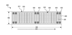
도 8은 하나의 1 차원(1D) CMUT 어레이(800)를 예시한다. 도 8은 1D CMUT 어레이(800)의 초음파 방출 면(812)의 평면도를 도시한다. 1D CMUT 어레이(800)는 CMUT 어레이(210) 및 CMUT 어레이(112)의 실시예이다. 1D CMUT 어레이(800)는 축(890)을 따라 배열된 CMUT 요소(820)의 1D 어레이를 갖는 기판(810)(예를 들어, 실리콘 기판)을 포함한다. 설명의 명확성을 위해, 모든 CMUT 요소(820)가 도 8에 표시되지 않았다. 축(890)은 관련된 장치가 카테터(110)에서 구현될 때 카테터(110)의 종축에 실질적으로 평행한 방향을 지칭한다. 여기서, 카테터(110)의 종축은 근위 단부(102)로부터 원위 단부(104)로 카테터(110)에 의해 설명된 일반적인 경로를 지칭한다. 이러한 경로는 직선일 수 있고 아닐 수도 있으며, 따라서 카테터(110)의 종축의 방향은 근위 단부(102)와 원위 단부(104) 사이의 경로를 따라 변할 수 있다.8 illustrates one one-dimensional (1D)
1D CMUT 어레이(800)는 축(890)을 따르는 범위(880) 및 축(890)에 수직한 방향으로의 범위(882)를 가진다. 일 실시예에서, 범위(880)는 범위(882)보다 더 크므로, 1D CMUT 어레이(800)는 축(890)을 따라 신장된다. 신체 채널(392)의 길이를 따라 일반적으로 지향된 축(890)을 갖는 신체 채널(392) 내로 삽입되도록 의도된 CMUT 어레이(800)의 실시예의 경우(도 3 참조), 범위(882)는 신체 채널(392)의 폭에 의해 한정될 수 있지만, 범위(880)는 신체 채널(392)의 길이를 따른 방향으로 표적 조직(380)의 전형적인 범위에 기초하여 구성될 수 있다. 요도 카테터에서의 구현에 적합한 일 실시예에서, 범위(882)는 2.5 내지 3.5 밀리미터 범위 또는 3.0 내지 3.2 밀리미터 범위이고, 범위(880)는 10 내지 50 밀리미터 범위에 있다. 예를 들어, 0.2 밀리미터의 중심-대-중심 간격을 갖는 128 개의 CMUT 요소(820)를 갖춘 실시예에서, 범위(880)는 대략 1 인치이다. 요도 카테터에서의 구현에 적합한 다른 실시예에서, 범위(882)는 5 밀리미터 이하이다.The
CMUT 요소(820)의 수는 본 발명의 범주로부터 벗어남이 없이, 도 8에 도시된 것과 상이할 수 있다. 예를 들어, 1D CMUT 어레이(800)는 128 또는 256 개의 CMUT 요소(820)를 포함할 수 있다. 각각의 CMUT 요소(820)는 도 3에 도시된 바와 같이 긴 직사각형의 형상을 가질 수 있거나, 사각형, 원형 또는 타원형과 같은 상이한 형상을 가질 수 있다.The number of
각각의 CMUT 요소(820)는 하나 이상의 CMUT 셀(150)을 포함한다. CMUT 요소(820)의 각각의 CMUT 셀(150)에서, 막(160)은 초음파 방출 면(812)과 동일한 방향을 향하는 CMUT 요소(820)의 측면(822)에 전극(162)을 가진다. (명확성을 위해 도 8에 도시되지 않은)각각의 CMUT 셀(150)의 전극(162)에 대한 전기 연결은 초음파 방출 면(812)에 위치되거나, 기판(810)을 통해 초음파 방출 면(812) 반대쪽의 기판(810)의 측면으로 통과할 수 있다. CMUT 요소(820)의 각각의 CMUT 셀(150)에서, 기판(180)(도 1 참조)은 1D CMUT 어레이(800)의 모든 CMUT 셀(150) 사이에 공유되고 단일 전기 연결을 갖는 기판(810)의 층일 수 있다. 이러한 층은 초음파 방출 면(812)과 대향하는 기판(810)의 측면으로부터 CMUT 요소(820)의 전극(162)에 웨이퍼를 통한 전기 연결에 의해 차단될 수 있다. 1D CMUT 어레이(800)가 카테터(110)에서 구현될 때, 유연한 케이블은 1D CMUT 어레이(800)의 전기 연결을 CMUT 요소(820)를 구동하도록 구성된 전자 회로에 연결할 수 있다. 이러한 전자 회로는 예를 들어, 핸들(120)에 위치되거나 주문형 집적 회로(ASIC)의 형태로 CMUT-TEC 장치(116)에 통합된다.Each
1D CMUT 어레이(800)는 초음파(270)의 빔포밍(beamforming)과 호환되며, 여기서 CMUT 요소(820) 중 일부는 다른 CMUT 요소(820)에 의해 수신된 것과 비교하여 위상 변위된 전기 구동 신호를 수신한다. 하나의 빔포밍 시나리오에서, CMUT 요소(820)는 8 개의 상이한 그룹으로 분할된다. 동일한 그룹에 속하는 모든 CMUT 요소(820)는 동일한 전기 구동 신호를 수신하지만, 다른 그룹의 CMUT 요소(820)는 상이한 전기 구동 신호를 수신할 수 있다. CMUT 요소(820)가 더 많거나 더 적은 그룹으로 분할될 수 있지만, 8 개의 상이한 그룹이 1D CMUT 어레이(800)에 의해 발생된 빔포밍 초음파의 충분한 공간 해상도를 제공하는 것으로 밝혀졌다.The
하나의 사용 시나리오에서, CMUT 요소(820) 중 일부는 표적 조직(280)을 치료하기 위해 초음파(270)를 발생하는데 전용인 반면에, 다른 CMUT 요소(820)는 표적 조직(280)의 초음파 이미징을 수행한다. 다른 사용 시나리오에서, CMUT 요소(820) 중 적어도 일부는 일부 기간 동안 표적 조직(280)의 치료를 위해 초음파를 발생할 수 있고, 다른 기간 동안 표적 조직(280)의 초음파 이미징을 수행할 수 있다.In one use scenario, some of the
특정 실시예에서, 1D CMUT 어레이(800)는 초음파 방출 면(812)에 배치되거나 초음파 방출 면(812) 내의 또는 그 근처의 기판(810)에 형성된 하나 이상의 센서(830/832)를 더 포함한다. 예시의 명확성을 위해, 모든 센서(830/832)가 도 8에 표시되지 않았다. 각각의 센서(830/832)는 센서(230)의 실시예이고 1D CMUT 어레이(800) 근처에서 조직의 특성을 감지한다. 일 실시예에서, 1D CMUT 어레이(800)는 하나 이상의 온도 센서(830) 및/또는 하나 이상의 압력 센서(842)를 포함한다. 센서(830/832)는 도 8에 도시된 바와 같이, CMUT 요소(820)에 의해 점유된 초음파 방출 면(812)의 일부분 내에 위치되거나, 대안적으로 초음파 방출 면(812)의 이러한 부분 외부에 위치될 수 있다. 도 2에 도시된 실시예에서, 센서(830/832)의 존재는 일부 CMUT 요소(820)의 활성 구역을 축소시킨다. 본 발명의 범주를 벗어남이 없이, 모든 CMUT 요소(820)는 동일한 크기일 수 있고, 센서(830/832)는 다른 CMUT 요소(820)와 비교하여 일부 CMUT 요소(820)의 크기를 공간적으로 제한함이 없이 초음파 방출 면(812)에 위치된다.In certain embodiments, the
1D CMUT 어레이(820)는 렌즈(510)가 CMUT 어레이(800)에 의해 방출된 초음파(270)의 범위를 축(890)에 수직한 치수로 조작하도록 CMUT-TEC 장치(500)에서 구현될 수 있다. 이러한 구현예에서, 초음파(270)의 빔포밍(beamforming)은 렌즈(510)의 작용과 조합되어 초음파(270)의 2 차원 포커싱을 달성할 수 있다.The
도 9는 1.5D CMUT 어레이(900)를 예시한다. 도 9는 1.5D CMUT 어레이(900)의 초음파 방출 면(812)의 평면도를 도시한다. 1.5D CMUT 어레이(900)는 CMUT 어레이(210) 및 CMUT 어레이(112)의 실시예이다. "1.5D"는 빔포밍 분야에서의 기술 용어이다. 1.5D 변환기 어레이는 (a) 1 차원에서 높은 공간 해상도 및 직교 2 차원에서 훨씬 더 제한된 공간 해상도를 가지며, (b) 제 1 치수와 평행하고 제 2 치수의 중심에 있는 선에 대해 대칭적인 방식으로 작동되는 2 차원 변환기 어레이이다. 예를 들어, 1.5D 변환기 어레이는 3 x 128 또는 3 x 256 변환기를 갖춘 어레이를 형성하기 위해 각각의 행에 128 또는 256 변환기를 갖춘 3 개의 행을 가질 수 있다.9 illustrates a 1.5
1.5D CMUT 어레이(900)는 CMUT 요소(820)의 1 차원 어레이가 3 행의 CMUT 요소: 중앙 행(930)의 CMUT 요소(920) 및 2 개의 외부 행(932)의 CMUT 요소(922)로 대체되는 것을 제외하면 1D CMUT 어레이(800)와 유사하다. 각각의 행(930 및 932)은 CMUT 요소(920/922)의 3 x N 어레이를 형성하기 위해 N CMUT 요소(920/922)(여기서, N은 128 또는 256과 같이 상당히 큰 정수임)를 가진다. CMUT 요소(922)는 CMUT 요소(820)와 유사하지만, 축(890)에 수직인 방향으로 더 작은 범위를 가질 수 있다. CMUT 요소(920)는 축(890)에 수직인 방향으로 CMUT 요소(920)보다 더 작은 범위를 갖는 것을 제외하면 CMUT 요소(920)와 유사하다. 본 발명의 범주를 벗어남이 없이, 1.5D CMUT 어레이(900)는 총 5 개의 행과 같은 더 많은 행의 CMUT 요소를 포함할 수 있다. 1.5D CMUT 어레이(900)는 축(890)에 수직인 치수에서의 빔포밍의 공간 해상도가 축(890)에 평행한 치수에서의 빔포밍의 공간 해상도보다 더 작지만, 축(890)에 수직한 치수에서 초음파의 어느 정도의 빔포밍을 허용한다. 이러한 빔 포밍은 1.5D CMUT 어레이(900)의 방출 면으로부터 떨어진 원하는 거리에서 초점을 달성하기 위해 축(890)에 직교하는 치수에서 1.5D CMUT 어레이(900)에 의해 방출된 초음파를 전자적으로 포커싱하는 역할을 할 수 있다. 1.5D CMUT 어레이(900)는 전자 빔포밍과 함께 초음파의 포커싱을 위한 렌즈(510)와 같은 렌즈로 구현될 수 있거나, 1.5D CMUT 어레이(900)는 렌즈(510) 없이 구현될 수 있고 포커싱을 위한 빔포밍에 의존할 수 있다.The 1.5
도 10은 1.75D CMUT 어레이(1000)를 예시한다. 도 10은 1.75D CMUT 어레이(1000)의 초음파 방출 면(812)의 평면도를 도시한다. 1.75D CMUT 어레이(1000)는 CMUT 어레이(210) 및 CMUT 어레이(112)의 실시예이다. "1.75D"는 빔포밍 분야의 기술 용어이다. 1.75D 변환기 어레이는 (a) 1 차원에서 높은 공간 해상도 및 직교 2 차원에서 훨씬 더 제한된 공간 해상도를 가지며, (b) 제 1 치수와 평행하고 제 2 치수의 중심에 있는 선에 대해 비대칭적인 방식으로 작동되는 2 차원 변환기 어레이이다. 예를 들어, 1.75D 변환기 어레이는 5 x 128 또는 5 x 256 변환기를 갖춘 어레이를 형성하기 위해 각각의 행에 128 또는 256 변환기를 갖춘 5 개의 행을 가질 수 있다.10 illustrates a 1.75
1.75D CMUT 어레이(1000)는 CMUT 요소의 추가 행을 포함하는 것을 제외하면 1.5D CMUT 어레이(900)와 유사하다. 1.75D CMUT 어레이(1000)는 5 개의 행의 CMUT 요소: 중앙 행(1030)의 CMUT 요소(1020), 행(1030)의 측면의 2 개의 행(1032)의 CMUT 요소(1032) 및 2 개의 외부 행(1034)의 CMUT 요소(1024)를 포함한다. 각각의 행(1030, 1032 및 1034)은 CMUT 요소(1020/1022/1024)의 5 x N 어레이를 형성하기 위해 N CMUT 요소(1020/1022/1024)(여기서, N은 128 또는 256과 같이 5보다 상당히 큰 정수임)를 가진다. CMUT 요소(1030)는 CMUT 요소(820)와 유사하지만, 축(890)에 수직인 방향으로 더 작은 범위를 가질 수 있다. CMUT 요소(1020)는 축(890)에 수직인 방향으로 CMUT 요소(1020)보다 더 작은 범위를 갖는 것을 제외하면 CMUT 요소(1020)와 유사하며, CMUT 요소(1024)는 축(890)에 수직인 방향으로 CMUT 요소(1022)보다 더 작은 범위를 갖는 것을 제외하면 CMUT 요소(1022)와 유사하다. 본 발명의 범주를 벗어남이 없이, 1.75D CMUT 어레이(1000)는 더 많은 행의 CMUT 요소를 포함할 수 있다. 1.75D CMUT 어레이(1000)는 축(890)에 수직인 치수에서의 빔포밍의 공간 해상도가 축(890)에 평행한 치수에서의 빔포밍의 공간 해상도보다 더 작지만, 축(890)에 수직한 치수에서 초음파의 어느 정도의 빔포밍을 허용한다. 이러한 빔 포밍은 1.75D CMUT 어레이(1000)의 방출 면으로부터 떨어진 원하는 거리뿐만 아니라 축(890)에 직교하는 치수를 따르는 원하는 위치에서 초점을 달성하기 위해 축(890)에 직교하는 치수에서 1.75D CMUT 어레이(1000)에 의해 방출된 초음파를 전자적으로 포커싱하는 역할을 할 수 있다. 1.75D CMUT 어레이(1000)는 전자 빔포밍과 함께 초음파의 포커싱을 위한 렌즈(510)와 같은 렌즈로 구현될 수 있거나, 1.75D CMUT 어레이(1000)는 렌즈(510) 없이 구현될 수 있고 포커싱을 위한 빔포밍에 의존할 수 있다.The 1.75
도 11은 2D 어레이로 배열된 복수의 CMUT 요소(1120)를 포함한 2 차원(2D) CMUT 어레이(1100)를 예시한다. CMUT 요소(1120)는 CMUT 요소(820)와 유사하다. 도 11은 2D CMUT 어레이(1100)의 초음파 방출 면(812)의 평면도를 도시한다. CMUT 어레이(1100)는 CMUT 어레이(210) 및 CMUT 어레이(112)의 실시예이다. 예시의 명확성을 위해, 도 11은 5 x 20 CMUT 요소(1120)를 갖는 것으로 2D CMUT 어레이(1100)를 도시하지만, 2D CMUT 어레이(1100)는 10 x 128 CMUT 요소(1120)와 20 x 256 CMUT 요소(1120)와 같은 더 많은 수의 CMUT 요소(1120)를 포함할 수 있다. 특정 실시예에서, 2D CMUT 어레이(1100)는 CMUT 어레이(900 및 1000)에 의해 제공되는 빔포밍의 관련된 공간 해상도보다 더 큰 공간 해상도의, 축(890)에 수직한 치수에서 빔포밍을 가능하게 한다.11 illustrates a two-dimensional (2D)
2D CMUT 어레이(1100)는 센서(1130) 및/또는 센서(1142)를 포함할 수 있다. 센서(1130)는 센서(830)와 유사하고, 센서(1132)는 센서(842)와 유사하다. 각각의 센서(1130/1132)는 CMUT 요소(1120)에 의해 형성된 어레이에서 하나의 부위를 점유할 수 있어서, 이러한 특정 부위는 CMUT 요소(1120) 대신에 센서(1130/1132)를 가진다. 대안적으로, 센서(1130/1132)는 CMUT 요소(1120)의 2D 어레이를 방해하지 않는 위치에 위치된다. 본 발명의 범주를 벗어남이 없이, CMUT 요소(1120)의 형상은 도 11에 도시된 것과 상이할 수 있다. 예를 들어, 각각의 CMUT 요소(1120)는 정사각형, 직사각형 또는 타원형일 수 있다.The
도 12a 및 도 12b는 하나의 CMUT-TEC 장치(1200)를 예시한다. CMUT-TEC 장치(1200)는 CMUT-TEC 장치(200)의 실시예이다. CMUT-TEC 장치(1200)는 열전 냉각기(1210)에 직접 배치되거나 형성된 CMUT 어레이(210)를 갖춘 열전 냉각기(1210)를 포함한다. 열전 냉각기(1210)는 열전 냉각기(220 또는 114)의 실시예이다. 도 12a는 CMUT-TEC 장치(1200)의 단면도이며, 여기서 단면도는 CMUT 어레이(210)의 초음파 방출 면(212)에 수직인 평면에서 취한 것이다. 도 12b는 열전 냉각기(1210)의 반도체의 평면도이고, 여기서 평면도는 초음파 방출 면(212)으로부터 열전 냉각기(1210)의 반도체 쪽 방향으로의 도면이다. 도 12a 및 12b는 다음 설명에서 함께 보는 것이 가장 바람직하다.12A and 12B illustrate one CMUT-
열전 냉각기(1210)는 복수의 n-형 반도체(1220) 및 전극(1230)에 의해 직렬로 전기적으로 커플링된 복수의 p-형 반도체(1222)를 포함하여, 직렬 커플링이 도 12a 및 도 12b의 선(1290)으로 표시된 바와 같이 n-형 반도체와 p-형 반도체 사이에서 교대한다. 본 발명의 범주를 벗어남이 없이, 전극(1230)은 도 12a 및 도 12b에 도시된 것과 상이하게 배열될 수 있고, 선(1290)은 상이한 경로를 취할 수 있다. 또한, n-형 반도체(1220) 및 복수의 p-형 반도체(1222)의 수는 도 12b에 도시된 것과 상이할 수 있음을 이해해야 한다. 작동시, CMUT 어레이(210)를 향하는 열전 냉각기(1210)의 저온 측(1252) 및 CMUT 어레이(210)의 반대로 향하는 열전 냉각기(1210)의 고온 측(1250)을 형성하기 위해 일련의 n-형 반도체(1220)와 복수의 p-형 반도체(1222)에 걸쳐 전압 강하가 인가된다. 열전 냉각기(1210)는 고온 측(1250)에 n-형 반도체(1220)와 p-형 반도체(1222)를 열적으로 커플링시키는 열 전도체(1240)를 더 포함한다. 선택적으로, 열전 냉각기(1210)는 또한, 저온 측(1252)에 n-형 반도체(1220)와 p-형 반도체(1222)를 열적으로 커플링시키는 열 전도체(1242)를 포함한다. 대안적으로, CMUT 어레이(210)의 일부분은 열 전도체(1242)를 형성한다. 각각의 열 전도체(1240 및 1242)는 전기 절연체이다. 일 예에서, 각각의 열 전도체(1240 및 1242)는 이산화 실리콘, 질화 실리콘 또는 다른 열 전도성 유전체의 박막으로 형성된다.The
CMUT-TEC 장치(1200)는 CMUT-TEC 장치(500)에 구성된 바와 같은 CMUT 어레이(210) 및 열전 냉각기(220)의 실시예를 형성한다. 도 12에 도시되지 않지만, CMUT-TEC 장치(1200)는 CMUT 어레이(210)의 초음파 방출 면(212)에 배치된 렌즈(510)를 더 포함할 수 있다.CMUT-
특정 실시예에서, CMUT-TEC 장치(1200)는 고온 측(1250)에 열적으로 커플링되고 고온 측(1250)의 반대로 열을 전도하도록 구성된 고체 열 전도체(1260)를 포함한다. 고체 열 전도체(1260)는 고체 열 전도체(710)의 실시예이다.In a particular embodiment, the CMUT-
도 13은 그 사이에 조정 가능한 각도를 갖는 2 개의 평면 CMUT 서브어레이(1310(1) 및 1310(2))를 갖춘 하나의 CMUT-TEC 장치(1300)를 도시한다. CMUT-TEC 장치(1300)는 CMUT-TEC 장치(200)의 실시예이다. CMUT 서브어레이(1310(1) 및 1310(2))는 각각의 열전 냉각기(1320(1) 및 1320(2))에 열적으로 커플링된다. 각각의 열전 냉각기(1320)와 쌍을 이루는 CMUT 서브어레이(1310)의 각각의 사례는 CMUT-TEC 장치(1200)와 유사할 수 있다. CMUT-TEC 장치(1300)는 각각, 열전 냉각기(1320(1) 및 1320(2))의 고온 측에 열적으로 커플링되는 고체 열 전도체(1330(1) 및 1330(2))를 더 포함할 수 있다.13 shows one CMUT-
CMUT-TEC 장치(1300)는 (a) CMUT 서브어레이(1310(2)) 및 관련 열전 냉각기(1320(2))(및 선택적으로 고체 열 전도체(1330(2)))를 (b) 화살표(1350)로 나타낸 바와 같이, CMUT 서브어레이(1310(1)) 및 관련 열전 냉각기(1320(1)(및 선택적으로 고체 열 전도체(1330(1)))에 대해 피봇 가능하게 하는 힌지(1340)를 포함한다. 이러한 피봇 행위는 CMUT 서브어레이(1310)에 의해 발생된 초음파(270)를 표적 조직(280)으로 지향시키고/시키거나 신체 채널(392)의 곡률을 따르게 하는 CMUT-TEC 장치(1300)의 능력을 개선하는 역할을 할 수 있다.The CMUT-
CMUT-TEC 장치(1300)는 축(890)을 따르는 방향으로 범위(1380)를 가진다. 범위(1380)는 예를 들어, 10 밀리미터 내지 50 밀리미터 범위 내에 있다.CMUT-
도 14는 그 사이에 조정 가능한 각도를 갖는 2 개의 평면 CMUT 서브어레이(1410(1) 및 1410(2))를 갖는 하나의 CMUT-TEC 장치(1400)의 사진도(pictorial view)이다. CMUT-TEC 장치(1400)는 CMUT 서브어레이(1410(1))와 동일 평면으로부터 멀어지는 각도(1420)만큼 CMUT 서브어레이(1410(2))의 피봇을 허용하는 CMUT-TEC 장치(1300)의 실시예이다. 각도(1420)는 10 내지 30 도와 같은 최대 30 도의 범위 내에 있다.14 is a pictorial view of one CMUT-
도 15는 서로로부터 각진 2 개의 평면 CMUT 서브어레이(1510(1) 및 1510(2))를 갖는 하나의 CMUT-TEC 장치(1500)를 예시한다. CMUT-TEC 장치(1500)는 CMUT-TEC 장치(200)의 실시예이다. CMUT 서브어레이(1510(1) 및 1310(2))는 각각의 열전 냉각기(1520(1) 및 1520(2))에 열적으로 커플링된다. 각각의 열전 냉각기(1520)와 쌍을 이루는 CMUT 서브어레이(1510)의 각각의 사례는 CMUT-TEC 장치(1200)와 유사할 수 있다. CMUT-TEC 장치(1500)는 각각 열전 냉각기(1520(1) 및 1520(2))의 고온 측에 열적으로 커플링되는 고체 열 전도체(1530(1) 및 1530(2))를 더 포함할 수 있다. 본 발명의 범주를 벗어남이 없이, 열전 냉각기(1520(1) 및 1520(2))는 CMUT 서브어레이(1510(1) 및 1510(2)) 모두에 열적으로 커플링되는 단일 열전 냉각기로서 구현될 수 있다.FIG. 15 illustrates one CMUT-
CMUT-TEC 장치(1500)는 CMUT 서브어레이(1510)의 초음파 방출 면(1512)이 서로로부터 특정 범위로 마주 보는 방식으로, (a) CMUT 서브어레이(1510(2)) 및 관련 열전 냉각기(1520(2))(및 선택적으로 고체 열 전도체(1530(2))를 (b) CMUT 서브어레이(1510(1)) 및 관련 열전 냉각기(1520(1))(및 선택적으로 고체 열 전도체(1530(1)))에 대해 각지게 위치시키는 기계적 커플러(1540)를 포함한다. 그에 따라서 CMUT-TEC 장치(1500)는 단일 평면 CMUT-TEC 장치에 의해 달성될 수 있는 것보다 더 큰 각도 범위를 가진다. 각각의 초음파 방출 면(1512)은 카테터(110)에서 구현될 때, CMUT-TEC 장치(1500)가 카테터(110)의 종축에 실질적으로 평행한 각각의 초음파 방출 면(1512)에 대해 지향되도록 축(890)과 실질적으로 평행하다. 요도(194)로부터 전립선(192)의 초음파 치료를 위해 의도된 구현예에서, CMUT-TEC 장치(1500)의 2 개의 초음파 방출 면(1512)은 예를 들어, CMUT-TEC 장치(1500)의 회전이 전립선(192)의 초음파 치료 동안 적거나 필요 없도록 전립선(192)의 큰 부분의 동시 초음파 노출을 촉진할 수 있다.The CMUT-
실시예에서, 초음파 방출 면(1512)의 법선 벡터(1514) 사이의 각도는 45 내지 90도, 예컨대 60 내지 65 도의 범위 내에 있다. 각각의 CMUT 서브어레이(1510)는 축(890)에 평행한 치수로 신장될 수 있다.In an embodiment, the angle between the
CMUT-TEC 장치(1500)는 축(890)에 직교하는 치수에서 범위(1582)를 가진다. 범위(1582)는 실시예에서 요도 카테터의 구현예와 호환될 수 있는, 예를 들어 2.5 mm 내지 3.5 mm의 범위 또는 2 mm 내지 5 mm의 범위 내에 있다.The CMUT-
도 16은 서로로부터 멀어지게 각진 2 개의 평면 CMUT 서브어레이(1610(1) 및 1610(2))를 갖춘 하나의 CMUT-TEC 장치(1600)의 사진도이다. CMUT-TEC 장치(1600)는 CMUT-TEC 장치(1500)의 실시예이며, 여기서 각각의 CMUT 서브어레이(1610)는 축(890)에 평행한 치수로 신장된다.16 is a photograph of one CMUT-
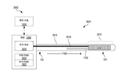
도 17은 CMUT-TEC 변환기 장치를 갖춘 하나의 카테터(1700)를 예시한다. 도 17은 카테터(1700)의 종축(1790)에 평행한 단면을 갖는 카테터(1700)의 단면도이다. 일 실시예에서, 카테터(1700)는 종축(1790)의 방향이 카테터(1700)의 길이를 따라 항상 일정하도록 강성 및 직선이다. 다른 실시예에서, 카테터(1700)는 유연하고 종축(1790)의 방향이 카테터(1700)의 길이를 따라 변할 수 있도록 구부러질 수 있다. 이러한 실시예와 관련하여, 도 17의 단면도는 그의 직선 구성의 카테터(1700)의 도면에 대응한다. 본 발명의 범주로부터 벗어남이 없이, 카테터(1700)는 강성 방식 또는 유연한 방식으로 항상 구부러지도록 구성될 수 있다. 이러한 경우에, 도 17의 단면도는 카테터(1700)의 직선화된 버전에 대응한다.17 illustrates one
카테터(1700)는 카테터(110)의 실시예이다. 카테터(1700)는 CMUT-TEC 장치(200) 및 고체 열 전도체(1720)를 포함한다. 카테터(1700)는 카테터(1700)의 원위 단부(104)에서 카테터(1700)의 카테터 팁(1710)에 CMUT-TEC 장치(200)를 포함한다. 고체 열 전도체(1720)는 CMUT-TEC 장치(200)의 열전 냉각기(들)(220)에 커플링되고 열전 냉각기(들)(220)로부터 멀어지게 열을 전도하기 위해 원위 단부(104)로부터 근위 단부(102) 쪽으로 카테터(1700)를 따라 연장한다.The
일 실시예에서, 고체 열 전도체(1720)는 구리, 은 및/또는 알루미늄과 같은 금속을 포함하거나 금속으로 실질적으로 구성된다. 일 예에서, 고체 열 전도체(1720)는 구리 로드와 같은 금속 로드이다. 다른 예에서, 고체 열 전도체(1720)는 복수의 편조 구리 와이어와 같은 복수의 편조 금속 와이어를 포함한다. 편조 금속 와이어는 예를 들어, 고체 열 전도체(1720)에 이용 가능한 경로가 직선이 아닌 경우에 고체 열 전도체(1720)가 굴곡되게 하도록 구성될 수 있다. 도 7 및 고체 열 전도체(710)를 참조하여 위에서 논의된 바와 같이, 그러한 유연성은 카테터(1700)가 신체 채널(392)에 배치될 때, 특히 카테터(1700)가 장기간 동안 신체 채널(392)에 남아 있거나 카테터(1700)의 재위치 설정/재방위가 요구되는 경우에 환자 편안함을 개선할 수 있다. 다른 실시예에서, 고체 열 전도체(1720)는 비금속 열 전도체, 예를 들어 열 전도성 나노섬유와 같은 열 전도성 나노재료를 포함하거나 이로 실질적으로 구성된다. 또 다른 실시예에서, 고체 열 전도체(1720)는 열 전도성 나노복합물을 포함하거나 이로 실질적으로 구성된다. 추가 실시예에서, 고체 열 전도체(1720)는 메타재료를 포함하거나 이로 실질적으로 구성된다.In one embodiment, solid
도 17에 도시된 실시예에서, 고체 열 전도체(1720)는 CMUT-TEC 장치(200)로부터 카테터(1700)의 외부로 제거된 열의 적어도 일부분을 전도하기 위해 근위 단부(102)의 극단까지 완전히 연장된다. 카테터(1700)의 이러한 실시예는 근위 단부(102)에서 또는 그를 넘어 고체 열 전도체(1720)에 커플링된 열 교환기(1730)와 함께 장치(1750)에서 구현될 수 있다. 열 교환기(1730)는 카테터(1700)가 내부로 삽입되는 신체 채널 외부의 고체 열 전도체(1720)를 냉각시킨다. 열 교환기(1730)는 액체 냉각 또는 가스 냉각을 사용할 수 있다. 일 예에서, 열 교환기(1730)는 고체 열 전도체(1720)의 냉각을 위한 냉각 핀을 포함한다. 다른 예에서, 열 교환기(1730)는 적어도 CMUT-TEC 장치(200)의 작동 중에 고체 열 전도체(1720)를 냉각시키기 위해 고체 열 전도체(1720)에 의해 액체 또는 가스를 순환시킨다. 장치(1750)는 핸들(1740)에서 열 교환기(1730)를 구현할 수 있다. 핸들(1740)은 핸들(120)의 실시예이다.In the embodiment shown in FIG. 17, the solid
도 17에 도시되지 않은 대안적인 실시예에서, 고체 열 전도체(1720)는 근위 단부(102)까지만 연장한다. 이러한 실시예에서, 고체 열 전도체(1720)는 카테터의 길이의 일부분을 따라서, CMUT-TEC 장치(200)로부터 제거된 열을 재분배할 수 있지만, 카테터의 장점을 취하여 비-표적 조직과 접촉하는 카테터 벽의 온도가 설정된 임계값을 초과하지 않도록 보장한다. 하나의 그러한 예에서, 고체 열 전도체(1720)는 (종축(1790)과 관련된)종 방향으로 카테터(1700)의 적어도 일부를 따라 열을 균일하게 재분배한다. 카테터(1700)의 이러한 실시예는 또한, 핸들(1740)에 커플링되어 열 교환기(1730)가 아닌 핸들(1740)을 포함하는 장치(1750)의 대안적인 실시예를 형성할 수 있다.In an alternative embodiment not shown in FIG. 17, the solid
카테터(1700)는 종축(1790)을 따르는 범위(1780) 및 종축(1790)에 직교하는 치수로 범위(1782)를 가진다. 축(1790)에 직교하는 카테터(1700)의 단면은 범위(1782)가 직경이 되도록 원형일 수 있다. 일 실시예에서, 범위(1780)는 원위 단부(104)가 표적 조직(380)에서 또는 그 근처에서 신체 채널(392)에 위치되지만 근위 단부(102)가 신체 채널(392)의 출구에 또는 외부 신체 채널(392)에 있을 정도로 충분히 길다. 특정 실시예에서, 범위(1782)는 2 내지 10 밀리미터의 범위 내에 있다. 그러한 일 실시예에서, 카테터(1700)는 요도 카테터로서 구성되며, 범위(1782)는 약 5 밀리미터와 같이 3 내지 7 밀리미터 범위 내에 있을 수 있다.The
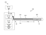
도 18은 도 17에서 사용된 것과 유사한 단면도로 CMUT-TEC 장치를 갖춘 다른 카테터(1800)를 예시한다. 카테터(1800)는 CMUT-TEC 장치(200)로부터 근위 단부(102)로의 전기 연결부(1820)를 더 포함하는 카테터(1700)의 실시예이다. 전기 연결부(1820)는 CMUT-TEC 장치(200)를 외부 전자 회로(1830)에 연결하도록 구성된다. 전자 회로(1830)는 (a) 일부 전기 연결부(1820)를 통해 CMUT-TEC 장치(200)의 CMUT 어레이(210)로 전송되는 구동 신호를 발생하는 초음파 구동 회로 및 (b) CMUT-TEC 장치(200)의 열전 냉각기(들)(220)에 전기 연결부(1820)의 다른 전기 연결부를 통해 전력을 공급하는 펠티에 구동 회로를 포함한다. 전자 회로(1830)는 일부 전기 연결부(1820)를 통해 CMUT 어레이(210)로부터 수신된 초음파 이미징 신호를 수신하고 처리하는 회로를 더 포함할 수 있다.FIG. 18 illustrates another
카테터(1800) 및 전자 회로(1830)는 장치(1850)에서 함께 구현될 수 있다. 일 실시예에서, 장치(1850)는 전자 회로(1830)를 포함하는 핸들(1840)을 포함한다. 핸들(1840)은 열 교환기(1730)를 더 포함할 수 있다.The
본 발명의 범주를 벗어남이 없이, 적어도 일부의 전기 연결부(1820)는 (a) 전자 회로(1830)를 CMUT-TEC 장치(200)에 커플링하고 (b) CMUT-TEC 장치(200)의 열전 냉각기(들)(220)로부터 멀리 열을 전도시키는 역할을 모두 수행할 수 있다. 이러한 경우에, 전기 연결부(1820)는 고체 열 전도체(1720)를 대체하거나, 고체 열 전도체(1720)의 열 전도 용량에 대한 요건을 감소시킬 수 있다. 그러한 일 예에서, 일부 전기 연결부(1820)는 동축 케이블이고 동축 케이블의 외부 전도체는 열전 냉각기(들)(220)로부터의 열을 제거하기 위해 열전 냉각기(들)(220)의 고온 측에 열적으로 커플링된다. 또한, 본 발명의 범주를 벗어남이 없이, 전자 회로(1830)는 장치(1850)의 외부에 구현되거나 예를 들어, 장치(1850)의 외부에서 제어 모듈(140)과 통합될 수 있다.Without departing from the scope of the present invention, at least some of the
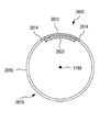
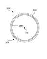
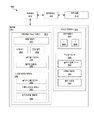
도 19 내지 도 21은 CMUT-TEC 장치를 갖춘 또 다른 카테터(1900)를 예시한다. 도 19는 도 17에서 사용된 것과 유사한 단면도로 카테터(1900)를 도시한다. 도 20은 도 19의 선(A-A')으로 나타낸 단면도로 카테터(1900)를 도시한다. 도 21은 도 19의 선(B-B')으로 나타낸 단면도로 카테터(1900)의 카테터 팁(1910)을 도시한다. 도 19 내지 도 21은 다음 설명에서 함께 보는 것이 가장 바람직하다.19-21 illustrate another
카테터(1900)는 카테터(1700)의 실시예이다. 카테터(1900)는 전기 연결부(1820)를 더 포함할 수 있으며, 그 경우에 카테터(1900)는 카테터(1800)의 실시예이다. 카테터(1900)는 카테터(1900)의 벽을 한정하는 관형 카테터 재킷(1920)을 더 포함한다. 관형 카테터 재킷(1920)은 CMUT-TEC 장치(200)의 초음파 방출 면(212) 위에 위치된 윈도우(1922)를 가진다. 윈도우(1922)는 렌즈(510) 또는 초음파를 전송할 수 있는 다른 재료를 수용할 수 있다. 관형 카테터 재킷(1920)은 외경(2010) 및 내경(2012)을 가진다. 요도 카테터로서 사용하도록 구성된 실시예에서, 외경(2010)은 약 5 밀리미터와 같은 3 내지 7 밀리미터의 범위 내에 있고, 내경(2012)은 약 4 밀리미터와 같은 2.5 내지 6.5 밀리미터의 범위 내에 있다. 관형 카테터 재킷은 경성 또는 연성일 수 있다. 일 실시예에서, 관형 카테터 재킷은 스테인레스 스틸과 같은 금속을 포함하거나 실질적으로 금속으로 구성된다. 관형 카테터 재킷(1920)의 이러한 실시예는 강성이다. 다른 실시예에서, 관형 카테터 재킷(1920)은 폴리머를 포함하거나 실질적으로 폴리머로 구성된다. 관형 카테터 재킷(1920)의 이러한 실시예는 강성 또는 연성일 수 있다. 관형 카테터 재킷(1920)은 고체 열 전도체(1720) 및 포함된 때, 전기 연결부(1820)를 포함한다(도 20 참조). 고체 열 전도체(1720) 및 선택적인 전기 연결부(1820)의 위치 설정은 본 발명의 범주를 벗어남이 없이, 도 20에 도시된 것과 상이할 수 있다. 예를 들어, 고체 열 전도체(1720)는 관형 카테터 재킷(1920)에 의해 한정된 벽에 더 가깝게 위치될 수 있다.The
특정 실시예에서, 관형 카테터 재킷(1920)은 관형 카테터 재킷(1920)의 벽을 통한 고체 열 전도체(1720)(및/또는 전기 연결부(1820))에 의해 수행되는 열의 전달을 방지하거나 감소시키기 위해 단열된다. 카테터(1900)가 신체 채널(392)(도 3 또는 도 6 참조)에 위치될 때, 관형 카테터 재킷(1920)의 그러한 단열은 열 방출 카테터(1900)로 인한 벽(390)에 대한 열-유도 손상을 방지하는 것을 돕는다. 하나의 시나리오에서, 관형 카테터 재킷(1920)의 단열은 고체 열 전도체(1720)가 벽(390)을 연소하는 것을 방지한다. 하나의 단열 실시예에서, 관형 카테터 재킷(1920)은 중합체 또는 고무와 같은 열악한 열 전도체인 고체 재료를 포함하거나 실질적으로 고체 재료로 구성된다. 다른 단열 실시예에서, 관형 카테터 재킷(1920)은 기공을 갖는 다공성 재료를 포함하거나 이로 실질적으로 구성되어 다공성 재료의 낮은 열 전도율을 초래한다. 또 다른 단열 실시예에서, 관형 카테터 재킷(1920)은 진공 층을 포함한다.In certain embodiments, the
대안적인 실시예에서, 전기 연결부(1820)의 절연 외피는 관형 카테터 재킷(1920)으로부터 고체 열 전도체(1720)를 적어도 부분적으로 열적으로 절연시켜서 관형 카테터 재킷(1920)이 열 전도성이거나 적어도 덜 효과적인 열 절연체일 수 있다. 그러한 실시예에서, 고체 열 전도체(1720)는 유리하게 전기 연결부(1820)에 의해 둘러싸일 수 있다.In an alternative embodiment, the insulating sheath of the
CMUT 어레이(210)(및 선택적인 렌즈(510))의 측면 근처의 영역(2190)에 예리한 에지 및 갭을 갖는 것으로 도 21에 도시되지만, 카테터 팁(1910)은 본 발명의 범주를 벗어남이 없이, 환자의 편안함을 개선하고 카테터(1900)가 내부로 삽입되는 신체 채널의 손상을 방지하기 위해 매끄러운 외부 표면으로 구성될 수 있다. 일 예에서, 영역(2190)에서 그리고 선택적으로 또한 렌즈(510)에서 카테터 팁(1910)의 윤곽은 관형 카테터 재킷(1920)의 윤곽의 연속이다.Although shown in FIG. 21 as having sharp edges and gaps in the
도 22는 제거 가능한 방식으로 카테터(1900)를 감싸도록 구성된 하나의 카테터 슬리브(2200)를 예시한다. 도 22는 도 19에 사용된 것과 유사한 단면도로 카테터 슬리브(2200) 및 카테터(1900)를 도시한다. 하나의 사용 시나리오에서, 카테터 슬리브(2200)는 표적 조직(380)을 초음파로 치료하기 위해 카테터(1900)를 신체 채널(392)에 삽입하기 전에 카테터(1900) 위에 놓인다. 초음파 치료 후, 카테터(1900)는 방향(2290)을 따라 카테터 슬리브(2200) 및 신체 채널(392)로부터 추출되는 반면에, 카테터 슬리브(2200)는 신체 채널(392)에 머무른다. 이러한 사용 시나리오에 대한 변형예에서, 카테터 슬리브(2200)는 먼저 카테터(1900) 없이 신체 채널(392) 내에 삽입되고, 그후 카테터(1900)는 카테터 슬리브(2200)에 삽입되어 카테터(1900)를 신체 채널(392)에 위치시킨다. 카테터 슬리브(2200)는 벽(390)(예를 들어, 전립선(192) 근처의 요도(194)의 벽)의 온도 및/또는 압력을 모니터링하기 위해 카테터(1900)에 의해 표적 조직(380)(예를 들어, 전립선(192))의 초음파 치료 후 한동안 신체 채널(392)(예를 들어, 요도(194))에 보유될 수 있다. 또한, 카테터 슬리브(2200)는 예를 들어, 치료 유도된 부기가 가라앉을 때까지 초음파 치료 후에 신체 채널(392)을 개방 상태로 유지하는 역할을 할 수 있다. 카테터 슬리브(2200)가 전립선(192)의 초음파 치료를 돕기 위해 요도(194)에 사용되도록 구성되는 실시예에서, 카테터 슬리브(2200)는 초음파 치료 후에 요도(194)에 남아서 요도의 완전한 막힘을 방지할 수 있으며(그렇지 않으면 치료 유도된 부기를 잠재적으로 초래함), 카테터 슬리브(2200)를 통해 방광(196)으로부터 소변을 통과시킨다.22 illustrates one
카테터 슬리브(2200)는 윈도우(2222)를 가진다. 카테터(1900)가 카테터 슬리브(2200)에 완전히 삽입될 때, 윈도우(2222)는 CMUT-TEC 장치(200)의 초음파 방출 면(212) 위에 위치된다. 윈도우(2222)는 실제 개구일 수 있거나, 윈도우(2222)는 초음파를 전송할 수 있는 재료로 덮일 수 있다. 대안적인 실시예에서, 카테터 슬리브(2200)는 윈도우(2222)를 갖지 않는다. 이러한 대안적인 실시예에서, 모든 카테터 슬리브(2200) 또는 카테터 슬리브(2200)의 일부분은 플라스틱과 같은 초음파 전송 재료로 만들어진다. 일 구현예에서, 초음파 전송 재료는 치료 동안 CMUT-TEC 장치(200)에 의해 점유된 영역을 둘러싸서, 360도에서 초음파 노출을 가능하게 한다. 카테터 슬리브(2200)의 이러한 구현예는 요도(194)에 대해 카테터 슬리브(2200)를 회전시킬 필요 없이 요도(194)로부터 모든 전립선(192)에 대한 접근을 제공할 수 있다.The
카테터 슬리브(2200)는 강성 또는 연성, 또는 이의 조합일 수 있다. 예를 들어, 카테터 팁(1910)을 수용하도록 구성된 카테터 슬리브(2200)의 원위 부분은 강성일 수 있는 반면에, 더 근위 부분은 연성일 수 있다. 카테터 슬리브(2200)의 완전히 또는 부분적으로 연성인 실시예는 카테터(1900)의 강성 또는 연성 실시예와 호환될 수 있다.The
카테터 슬리브(2200)는 단열 층을 포함하거나 실질적으로 단열 재료로 구성될 수 있어서, 카테터 슬리브(2200)는 고체 열 전도체(1720)에 의해 전도된 열로부터 벽(390)을 보호할 수 있다.The
도 23은 CMUT-TEC 장치(200) 및 그로부터 관련된 전기와 열 연결부의 제거를 허용하는 관형 카테터 재킷(2300)을 사용하는 CMUT-TEC 장치(200)를 갖춘 하나의 카테터(2350)를 예시한다. 카테터(2350)는 관형 카테터 재킷(1920)을 제거 가능한 관형 카테터 재킷(2300)으로서 구현하여, CMUT-TEC 장치(200), 고체 열 전도체(1720) 및 선택적인 전기 연결부(1820)를 방향(2390)을 따라서 관형 카테터 재킷(2300)으로부터의 추출을 허용하는 카테터(1900)의 실시예이다. 제거 가능한 관형 카테터 재킷(2300)의 기능은 도 22를 참조하여 위에서 논의된 카테터 슬리브(2200)의 기능과 유사할 수 있다.23 illustrates one
관형 카테터 재킷(2300)은 윈도우(2312)을 가진다. CMUT-TEC 장치(200)가 관형 카테터 재킷(2300)에 완전히 삽입될 때, 윈도우(2312)는 CMUT-TEC 장치(200)의 초음파 방출 면(212) 위에 위치된다. 윈도우(2312)는 실제 개구일 수 있거나, 윈도우(2312)는 초음파를 전송할 수있는 재료일 수 있다.The
함께, 관형 카테터 재킷(2300), CMUT-TEC 장치(200), 고체 열 전도체(1720), 및 선택적으로 전기 연결부(1820)는 카테터(2350)를 형성한다.Together, the
도 24는 고체 상태 냉각기능을 갖춘 하나의 카테터 또는 카테터 슬리브(2400)를 예시한다. 카테터/카테터 슬리브(2400)는 관형 벽(2410) 및 관형 벽(2410)에 커플링된 적어도 하나의 열전 냉각기(2420)를 포함한다. 관형 벽(2410)은 신체 채널(392) 내에 삽입되도록 구성되고, 열전 냉각기(들)(2420)는 신체 채널(392)의 벽(390)의 적어도 일부분을 냉각시키도록 구성된다. 열전 냉각기(들)(2420)는 열전 냉각기(들)(2420)와 벽(390) 사이의 직접적인 물리적 접촉을 통해 벽(390)을 냉각시킬 수 있거나, 열전 냉각기(들)(2420)는 관형 벽(2410)을 통한 열 커플링을 통해 벽(390)을 냉각할 수 있다. 관형 벽(2410)은 예를 들어, 관형 카테터 재킷 또는 카테터 슬리브의 관형 벽이다. 후자의 경우에, 카테터 슬리브는 카테터 슬리브(2200)에 대해 논의된 것과 유사한 제거 가능한 방식으로 열전 냉각기(2420)와 같은 카테터/카테터 슬리브(2400)의 다른 부분을 감쌀 수 있다. 열전 냉각기(들)(2420)에 더하여, 카테터/카테터 슬리브(2400)는 벽(390)의 냉각 이외의 하나 이상의 다른 목적을 수행하는 다른 기능을 포함할 수 있다.24 illustrates one catheter or
관형 벽(2410)은 강성 또는 연성일 수 있다. 일 실시예에서, 관형 벽(2410)은 스테인리스 스틸과 같은 금속을 포함하거나 이로 실질적으로 구성된다. 관형 벽(2410)의 이러한 실시예는 강성이다. 다른 실시예에서, 관형 벽(2410)은 중합체를 포함하거나 이로 실질적으로 구성된다. 관형 벽(2410)의 이러한 실시예는 강성 또는 연성, 또는 이의 조합일 수 있다.The
도 25는 관형 벽(2510)에 커플링된 적어도 하나의 열전 냉각기(2520)를 갖는 하나의 카테터 또는 카테터 슬리브(2500)를 예시한다. 카테터/카테터 슬리브(2500)는 카테터/카테터 슬리브(2400)의 실시예이며, 여기서 열전 커플링은 신체 채널(392)의 벽(390)에 열적으로 커플링되도록 관형 벽(2410) 내에 또는 그 위에서 구현된다. 카테터/카테터 슬리브(2500)는 또한, 관형 카테터 재킷(1920)의 실시예를 형성할 수 있다. 도 25의 실시예에서, 각각의 열전 냉각기(2520)는 관형 벽(2510)의 외부에 있다. 이러한 실시예에서, 각각의 열전 냉각기(2520)는 벽(390)을 냉각하기 위해 벽(390)과 직접 물리적으로 접촉할 수 있다. 다른 실시예에서, 각각의 열전 냉각기(2520)는 관형 벽(2510)의 내부에 있거나 관형 벽(2510)의 재료 내에 형성되어서, 각각의 열전 냉각기(2520)는 관형 벽(2510)의 관련 부분이 벽(390)에 열적으로 결합될 때 벽(390)에 열적으로 커플링된다. 하나의 사용 시나리오에서, 열전 냉각기(들)(2520)는 벽(390)의 이러한 부분을 통한 표적 조직(280)의 초음파 치료 전 또는 후에 벽(390)의 일부분을 냉각시킨다. 이러한 시나리오에서, 카테터/카테터 슬리브(2500)는 CMUT 어레이(112)가 벽(390)의 이러한 부분을 통해 표적 조직(280)을 초음파에 노출시키기 위해 위치되기 전 및/또는 후에 열전 냉각기(들)(2520)가 벽(390)의 일부와 접촉하도록 냉각기능과 초음파 치료 사이에서 신체 채널(392)에서 회전될 수 있다.25 illustrates one catheter or
특정 실시예에서, 카테터/카테터 슬리브(2500)는 관형 벽(2510) 내부에 CMUT 어레이(112) 및 관련 전기 연결부(1820)를 수용하도록 구성되며, 따라서 비-표적 조직(290)의 고체 상태 냉각으로 표적 조직(280)의 초음파 치료를 위한 카테터(2550)를 형성한다. 카테터(2550)의 그러한 실시예에서, 관형 벽(2510)은 CMUT 어레이(112)로부터 표적 조직(280)으로 초음파 방출을 허용하는 윈도우(2512)를 형성하거나 포함할 수 있다. 윈도우(2512)는 윈도우(2312)와 유사할 수 있다. 카테터(2550)는 (a) 카테터 벽에 커플링된 열전 냉각기(들)(114)의 실시예 및 (b) 카테터 벽에 의해 수용된 공간 내의 CMUT 어레이(112)를 가지는 CMUT-TEC 장치(200)의 실시예를 구현하는 카테터(110)의 실시예이다. 함께, CMUT 어레이(112)와 열전 냉각기(들)(114)는 CMUT-TEC 장치(200)의 실시예를 형성한다.In certain embodiments, the catheter /
카테터(2550)의 일 실시예에서, 관형 벽(2510)은 방향(2590)을 따라 관형 벽(2510)으로부터 CMUT 어레이(112) 및 관련 전기 연결부(1820)의 추출을 허용한다. 관형 벽(2510)의 이러한 실시예는 열전 냉각기(들)(2520)와 협력하여 열전 냉각기(들)(2520)를 더 포함하는 관형 카테터 재킷(2300)의 실시예를 형성한다. 카테터(2550)의 관련 실시예는 카테터(2550)의 열전 냉각기(들)(2520)가 관형 벽(2510)에 커플링되는 것을 제외하면 카테터(2350)와 유사하다.In one embodiment of
도 26은 적어도 하나의 열전 냉각기(2520) 및 관형 벽(2610)에 기계적으로 커플링된 고체 열 전도체(2620)를 갖는 다른 카테터 또는 카테터 슬리브(2600)를 예시한다. 카테터/카테터 슬리브(2600)는 카테터/카테터 슬리브(2500)의 실시예이고, 관형 벽(2610)은 관형 벽(2510)의 실시예이고, 고체 열 전도체(2620)는 고체 열 전도체(1720)의 실시예이다. 고체 열 전도체(2620)는 열전 냉각기(들)(2520)의 작동 중에 열전 냉각기(들)(2520)의 고온 측으로부터 멀리 열을 전도하기 위해 열전 냉각기(들)(2520)에 열적으로 커플링된다.26 illustrates another catheter or
고체 열 전도체(2620)와 벽(390) 사이의 직접적인 물리적 접촉을 피하기 위해서, 고체 열 전도체(2620)는 관형 벽(2610)의 내부에, 적어도 열전 냉각기(들)(2520)로부터 멀어지는 관형 벽(2610)의 부분(2680) 위에 위치된다. 관형 벽(2610)은 관형 벽(2610)을 통해 고체 열 전도체(2620)로부터의 열 전달을 추가로 방지하고, 따라서 관형 벽(2610)과 접촉하는 벽(390)의 일부분을 열 유도 손상으로부터 보호하도록 단열성일 수 있다. 관형 벽(2610)의 단열 실시예는 관형 카테터 재킷(1920)에 대해 도 19를 참조하여 위에서 논의된 것과 유사한 재료로 구성될 수 있다. 대안적으로, 관형 벽(2610)이 열 전도체이면, 고체 열 전도체(2620)는 관형 벽(2610)으로부터 열적으로 절연될 수 있다.To avoid direct physical contact between the
관형 벽(2610)의 근위 단부(2602)까지 완전히 연장하는 것으로 도 26에 도시되지만, 고체 열 전도체(2620)는 도 17 및 고체 열 전도체(1720)를 참조하여 위에서 논의된 바와 같이 열전 냉각기(들)(2520)로부터 근위 단부(2602) 쪽으로 일부만 연장할 수 있다.Although shown in FIG. 26 as extending completely to the
특정 실시예에서, 카테터/카테터 슬리브(2600)는 도 25 및 카테터/카테터 슬리브(2500)를 참조하여 위에서 논의된 것과 유사한 방식으로 CMUT 어레이(112) 및 관련 전기 연결부(1820)를 관형 벽(2610) 내부에 수용하고, 따라서 비-표적 조직(290)의 고체 상태 냉각기능으로 표적 조직(280)의 초음파 치료를 위한 카테터(2650)를 형성하도록 구성된다. 카테터(2650)의 그러한 실시예에서, 관형 벽(2610)은 CMUT 어레이(112)로부터 표적 조직(280)으로 초음파 방출을 허용하는 윈도우(2512)를 포함할 수 있다. 카테터(2650)는 카테터(1800 또는 1900)의 실시예이다.In certain embodiments, the catheter /
카테터(2650)의 일 실시예에서, 관형 벽(2610)은 방향(2690)을 따라 관형 벽(2610)으로부터 CMUT 어레이(112) 및 관련 전기 연결부(1820)의 추출을 허용한다. 관형 벽(2610)의 이러한 실시예는 열전 냉각기(2520) 및 고체 열 전도체(2620)와 협력하여 열전 냉각기(들)(2520) 및 고체 열 전도체(2620)를 더 포함하는 관형 카테터 재킷(2300)의 실시예를 형성한다. 카테터(2650)의 관련 실시예는 카테터(2650)의 열전 냉각기(들)(2520) 및 고체 열 전도체(2620)가 관형 벽(2610)에 커플링되는 것을 제외하면 카테터(2350)와 유사하다.In one embodiment of
도 27a 및 도 27b는 열전 냉각기능을 갖춘 하나의 카테터 또는 카테터 슬리브(2700)를 예시한다. 카테터/카테터 슬리브(2700)는 카테터/카테터 슬리브(2500)의 실시예이다. 도 27a 및 도 27b는 카테터/카테터 슬리브(2700)의 직교 단면도이며 다음 설명에서 함께 보는 것이 가장 바람직하다. 카테터/카테터 슬리브(2700)는 관형 벽(2710) 및 관형 벽(2710)의 외부에 하나 이상의 열전 냉각기(2720)를 포함한다. 열전 냉각기(들)(2720)는 관형 벽(2710)의 원주 둘레에 걸쳐 있거나 관형 벽(2710)의 원주를 따라 하나 이상의 섹션만을 덮을 수 있다. 열전 냉각기(2720)는 열전 냉각기(2520)의 실시예이며 카테터/카테터 슬리브(2500) 및 카테터/카테터 슬리브(2600) 중 하나에서 구현될 수 있다.27A and 27B illustrate one catheter or
각각의 열전 냉각기(2720)는 (a) 관형 벽(2710)에 배치된 열 전도체(2730), (b) 관형 벽(2710)으로부터 이격된 열 전도체(2732), 및 (c) 금속 전극들(2750 및 2752)에 의해 직렬로 전기적으로 연결되어 n-형 반도체(2740)와 p-형 반도체(2742) 사이에서 교대하는 복수의 n-형 반도체(2740) 및 복수의 p-형 반도체(2742)를 포함한다. 열 전도체(2730 및 2732)는 전기 절연체이다. 작동시, 일련의 n-형 반도체(2740) 및 p-형 반도체(2722)에 걸쳐 전압 강하가 인가되어 신체 채널(392)의 벽(390)을 냉각할 수 있는 열 전도체(2732)에서 저온 측을 형성한다.Each
일 실시예에서, 열전 냉각기(들)(2720)를 지지하는 관형 벽(2710)의 적어도 일부는 강성이며, n-형 반도체(2740) 및 p-형 반도체(2722)는 관형 벽(2710)의 곡률과 일치하는 구성으로 견고하게 커플링된다. 다른 실시예에서, 열전 냉각기(들)(2720)를 지지하는 관형 벽(2710)의 적어도 일부분은 연성이고, 금속 전극(2750 및 2752) 및 열 전도체(2730 및 2732)는 유연하여 열전 냉각기(들)(2720)가 관형 벽(2710)의 관련 부분의 굽힘에 순응할 수 있다.In one embodiment, at least a portion of the
도 27b에 도시되지 않지만, 카테터/카테터 슬리브(2700)의 외부 표면은 매끄러울 수 있다. 또한, 본 발명의 범주를 벗어남이 없이, 열전 냉각기(2720)는 관형 벽(2710)의 일부분을 대체할 수 있다. 또한, 열전 냉각기(2720)는 본 발명의 범주를 벗어남이 없이, 관형 벽(2710)의 내부에 구현될 수 있고 관형 벽(2710)에 열적으로 커플링될 수 있다. 이러한 구현예에서, 관형 벽(2710)이 열적으로 커플링되는 관형 벽(2710)의 적어도 일부는 열전 냉각기(2720)가 관형 벽(2710)을 통해 신체 채널(392)의 벽(390)을 냉각시키도록 열 전도된다. 그러한 하나의 구현예가 도 28a 내지 도 28d를 참조하여 아래에서 논의된다.Although not shown in FIG. 27B, the outer surface of the catheter /
도 28a 내지 도 28d는 열전 냉각기능을 갖춘 다른 카테터 또는 카테터 슬리브(2800)를 예시한다. 카테터/카테터 슬리브(2800)는 카테터/카테터 슬리브(2500)의 실시예이다. 도 28a는 카테터/카테터 슬리브(2800)의 사시도이다. 도 28b는 종축(1790)에 직교하는 평면에서 카테터/카테터 슬리브(2800)의 원위 단부(104) 근처에서 취한 카테터/카테터 슬리브(2800)의 단면도이다(도 28a의 화살표 28B-28B' 참조). 도 28c는 종축(1790)에 직교하는 평면에서 카테터/카테터 슬리브(2800)의 근위 단부(102)를 향해 추가로 취해진 카테터/카테터 슬리브(2800)의 단면도이다(도 28a의 화살표 28C-28C' 참조). 도 28a 내지 도 28c는 다음 설명에서 함께 보는 것이 가장 바람직하다.28A-28D illustrate another catheter or
카테터/카테터 슬리브(2800)는 (a) 관형 벽(2810), (b) 관형 벽(2810)의 열 전도성 패드(2812)에 열적으로 그리고 기계적으로 커플링되는 하나 이상의 열전 냉각기(2820), 및 (c) 열전 냉각기(들)(2820)에 열적으로 커플링된 고체 열 전도체(2830)를 포함한다. 작동시, 각각의 열전 냉각기의 저온 측은 관형 벽(2810)과 열적으로 연결되고, 각각의 열전 냉각기의 고온 측은 고체 열 전도체(2830)와 열적으로 연결된다. 열전 냉각기(2820)는 열전 냉각기(2520)의 실시예이며 카테터/카테터 슬리브(2500) 및 카테터/카테터 슬리브(2600) 중 하나에서 구현될 수 있다. 각각의 열전 냉각기(2820)는 열전 냉각기(2720)와 유사한 구조일 수 있다. 관형 벽(2810)은 카테터/카테터 슬리브(2500)의 관형 벽(2510) 및 카테터/카테터 슬리브(2600)의 관형 벽(2610)의 실시예이다. 관형 벽(2810)에서, 열 전도성 패드(2812)는 관형 벽(2810)의 열 전도성 부분(2816)으로부터 열 전도성 패드(2812)를 열적으로 절연시키는 단열체(2814)에 의해 둘러싸인다. 열 전도성 부분(2816)은 예를 들어, 열 전도성 패드(2812) 및 열 절연체(2814)를 제외한 모두 관형 벽(2810)이다. 일 구현에서, 열 전도성 부분(2816)은 스테인리스 스틸과 같은 금속이다. 열 전도성 패드(2812)는 또한 금속일 수 있다.The catheter /
관형 벽(2810)의 다른 부분으로부터 열 전도성 패드(2812)의 단열은 열전 냉각기(들)(2820)에 의해 냉각되는 관형 벽(2810)의 구역(및 이에 따라 관형 벽(2810)과 접촉하는 인접 조직)을 제한한다. 이러한 구역 제한은 열전 냉각기(들)(2820)가 상당히 큰 관형 벽(2810) 부분 또는 모든 관형 벽(2810)과 열적으로 연결되면(이는 열전 냉각기(들)(2820)의 과부하를 초래할 수 있음) 달성 가능한 냉각기능과 비교하여 열전 냉각기(들)(2820)에 의한 더욱 효과적인 냉각을 용이하게 할 수 있다.The thermal insulation of the thermally
고체 열 전도체(2830)는 관형 벽(2810) 내부에 배치되고 열전 냉각기(들)(2820)로부터 근위 단부(102) 쪽으로 연장한다. 고체 열 전도체(2830)는 근위 단부(102)까지 완전히 연장되거나 근위 단부(102)까지 일부만 연장할 수 있다. 고체 열 전도체(2830)는 고체 열 전도체(1720)의 실시예이다. 실시예에서, 카테터/카테터 슬리브(2800)는 온도를 허용 가능한 수준으로 유지하면서 열을 수용하기 위한 관형 벽(2810)의 열 질량의 장점을 취하면서, 고체 열 전도체(2830)에 의해 전도된 열을 관형 벽(2810)으로 재분배하도록 구성된다. 이러한 실시예에서, 고체 열 전도체(2830)는 예를 들어, 하나 이상의 열 커넥터(2840)를 통해 관형 벽(2810)의 연장 부분 위로 열 전도성 부분(2816)과 열적으로 연결되어, 열 전도성 패드(2812)로부터의 열이 관형 벽(2810)의 상당히 큰 부분으로 재분배된다. 관형 벽(2810)의 이러한 더 큰 부분의 온도가 이러한 공정 동안 증가하고 인접한 조직을 잠재적으로 가열할 수 있지만, 열이 재분배되는 관형 벽(2810)의 큰 부분의 구역(영역)은 온도 증가가 수용 가능한 범위 내에 있도록 충분히 클 수 있다. 다른 실시예에서, 고체 열 전도체(2830)는 비-열 전도성 브리지에 의해 기계적으로 지지되어 고체 열 전도체(2830)가 관형 벽(2810)에 대한 열 단락의 형성을 방지한다.Solid
고체 열 전도체(2810)에 의해 점유되는 카테터/카테터 슬리브(2800)의 길이를 따른 임의의 단면에서, 열 커넥터(2840)의 수는 본 발명의 범주를 벗어남이 없이, 도 28c에 도시된 4 개의 열 커넥터(2840)보다 더 작거나 클 수 있다. 또한, 하나 이상의 열 커넥터(2840)는 슬래브 형상이고 종축(1790)의 연장된 세그먼트를 따라 고체 열 전도체(2830)와 관형 벽(2810) 사이에서 가교 연결될 수 있다. 대안적으로, 각각 관형 벽(2810)의 각각의 국소 부분에 연결되는 몇몇 로드 형상의 열 커넥터(2840)는 열을 관형 벽(2810)의 큰 부분으로 재분배하도록 협력할 수 있다. 일 구현예에서, 열 커넥터(들)(2840)는 관형 벽(2810)의 세그먼트에 걸쳐서 열을 균일하게 또는 적어도 대략 균일하게 재분배하도록 배열된다. 열 커넥터(들)(2840)의 형상 및 두께는 이러한 균일하거나 대략 균일한 열 재분배를 달성하기 위해서 종축(1790)을 따른 위치의 함수일 수 있다.At any cross-section along the length of the catheter /
본 발명의 범주를 벗어남이 없이, 열 전도성 패드(2812)는 열전 냉각기(들)(2820)의 저온 측 열 전도체로서 기능을 할 수 있다.Without departing from the scope of the present invention, the thermally
도 28d는 카테터/카테터 슬리브(2800)의 대안적인 실시예(2800')를 예시한다. 도 28은 카테터/카테터 슬리브(2800')의 단면도이며, 여기서 단면은 도 28c와 동일한 방식으로 취해진다. 카테터/카테터 슬리브(2800')는 (a) 관형 벽(2810)의 열 전도성 부분(2816)이 단열 부분(2816')으로 대체되고 (b) 고체 열 전도체(2830) 및 선택적 열 커넥터(2840)가 고체 열 전도체(2830')로 대체된다는 점을 제외하면 카테터/카테터 슬리브(2800)와 유사하다. 고체 열 전도체(2830')는 관형 벽(2810) 내부에, 예를 들어 단열 부분(2816')의 내부 표면에 인접하거나 심지어 직접적으로 배치된 중공 원통형 전도체이다. 일 구현예에서, 고체 열 전도체(2830')는 근위 단부(102)까지 완전히 연장하고 관형 벽(2810)으로부터 열의 적어도 일부분, 예를 들어 열교환기로 전도하도록 구성된다. 다른 구현예에서, 고체 열 전도체(2830')의 열 질량은 열전 냉각기(들)(2820)에 의해 효과적인 냉각을 허용하면서 열전 냉각기(들)(2820)에 의해 포획된 열을 수용하는데 충분하다. 고체 열 전도체(2830')의 두께는 열전 냉각기(들)(2820)로부터 최적의 열 재분배 및 열 제거를 달성하기 위해서 종축(1790)을 따르는 위치의 함수일 수 있다.28D illustrates an alternative embodiment 2800 'of the catheter /
일 실시예에서, 단열 부분(2816')은 유연하고(예를 들어, 유연한 중합체)이고 고체 열 전도체(2830')는 편조 와이어 커넥터이며, 따라서 카테터/카테터 슬리브(2810)는 그의 길이의 적어도 일부를 따라서 유연하다. 이러한 유연성은 환자의 편안함을 증가시킬 수 있다.In one embodiment, the insulating portion 2816 'is flexible (eg, flexible polymer) and the solid thermal conductor 2830' is a braided wire connector, so that the catheter /
도 29는 신체 채널(392)의 더 넓은 부분에 고정되면서 신체 채널(392)로부터 표적 조직(280)의 초음파 치료를 위해 카테터를 감싸도록 구성된 하나의 카테터 슬리브(2900)를 예시한다. 하나의 사용 시나리오에서, 카테터 슬리브(2900)는 카테터(1700) 또는 카테터(2400)를 감싼다. 카테터 슬리브(2900)는 카테터 슬리브(2200)의 실시예를 형성할 수 있다. 대안적으로, 카테터 슬리브(2900)는 카테터를 영구적으로 감싸도록 구성된다.FIG. 29 illustrates one
카테터 슬리브(2900)는 CMUT 어레이(210) 또는 CMUT 어레이(112)와 같은 카테터의 초음파 변환기 어레이에 의해 방출된 초음파를 전송할 수 있는 윈도우(2912)를 갖는 관형 케이싱(2910)을 포함한다. 윈도우(2912)는 개구 또는 초음파를 전송할 수 있는 재료일 수 있다. 카테터 슬리브(2900)는 카테터 슬리브(2900)의 원위 단부(104)에 장착된 팽창 가능한 풍선(balloon)(2920), 및 그의 팽창을 위해 팽창 가능한 풍선으로 유체를 유도하여 팽창 가능한 풍선을 신체 채널(392)의 더 넓은 부분에 고정시키는 도관(2922)을 더 포함한다. 선택적으로, 카테터 슬리브(2900)는 팽창 가능한 풍선(2920)에 대한 관형 케이싱(2910)의 회전을 허용하는 회전 조인트(2940)를 더 포함한다. 회전 조인트(2940)는 CMUT 어레이(210)가 카테터 슬리브(2900)와 커플링될 때 종축(1790)을 중심으로 CMUT 어레이(210)의 회전을 용이하게 할 수 있다. 일 예에서, 회전 조인트(2940)는 -135 도 내지 +135 도의 범위 내에서 CMUT 어레이(210)의 회전을 허용한다. 일 실시예에서, 회전 조인트(2940)는 종축(1790)을 중심으로, 예를 들어 5 도 또는 10 도마다 CMUT 어레이(210)의 이산된 복수의 방위를 허용하도록 구성된다.The
카테터 슬리브(2900)는 원위 단부(104)에 있는 유체 포트(2930) 및 유체 포트(2930)를 경유하여 신체 채널(392)로부터 수용된 유체를 카테터 슬리브(2900)를 통해 근위 단부(102)로 그리고 카테터 슬리브(2900)의 외부로 통과시키는 도관(2932)을 더 포함할 수 있다.The
카테터 슬리브(2900)는 도관(2922)을 경유하여 팽창 가능한 풍선(2920)을 팽창시키기 위해 유체를 공급하고 선택적으로 도관(2932)을 경유하여 신체 채널(392)로부터 유체를 수용하는 외부 유체 취급 시스템과 커플링될 수 있다.
관형 케이싱(2910)은 강성 또는 연성, 또는 이의 조합일 수 있다.The
도 30은 방광(196)에 고정되면서 요도(194) 내부로부터 전립선(192)의 초음파 치료를 위한 요도 카테터(3090)를 수용하도록 구성된 하나의 요도 카테터 슬리브(3000)를 예시한다. 요도 카테터(3090)는 예를 들어, 카테터(1700) 또는 카테터(2400)의 실시예이다. 카테터 슬리브(3000)는 요도(194)로부터 전립선(192)의 초음파 치료에 특히 적합한 카테터 슬리브(2900)의 실시예이다. 카테터 슬리브(3000)는 카테터 슬리브(2200)의 실시예를 형성할 수 있다. 대안적으로, 카테터 슬리브(3000)는 요도 카테터를 영구적으로 감싸도록 구성된다. 설명의 명확성을 위해, 도 30은 카테터 슬리브(3000)의 유체 도관(들) 및 선택적 회전 조인트(2940)를 도시하지 않는다.30 illustrates one
작동시, 카테터 슬리브(3000)는 요도 카테터(3090)와 함께 또는 요도 카테터(3090)를 카테터 슬리브(3000)에 삽입하기 전에 요도(194)에 삽입된다. 다음에, 카테터 슬리브(3000)의 팽창 가능한 풍선(3020)이 팽창되어 카테터 슬리브(3000)를 방광(196)에 고정시킨다. 카테터 슬리브(3000)는 예를 들어, CMUT 어레이(210) 또는 CMUT 어레이(112)를 사용하여 전립선(192)을 요도 카테터(3090)의 팁에 의해 방출된 초음파에 노출시키기 위해 전립선(192)에서 요도 카테터(3090)의 팁의 위치 설정을 용이하게 한다. 사용의 일 예에서, 요도 카테터(3090)는 요도 카테터(3090)에 의해 전립선(192)의 초음파 치료 후 카테터 슬리브(3000)로부터 추출되는 반면에, 카테터 슬리브(3000)는 더 긴 기간 동안 제자리에 남아 있다. 다른 사용 예에서, 카테터 슬리브(3000) 및 요도 카테터(3090)는 요도(194)로부터 함께 제거된다. 요도(194)로부터 카테터 슬리브(3000)의 제거는 팽창 가능한 풍선(3020)의 수축 후에 일어난다.In operation, the
도 30에 도시되지 않지만, 카테터 슬리브(3000)는 방광(196)으로부터 카테터 슬리브(3000)를 통해 요도(192) 외부로 소변을 통과시키기 위해 도관(2932)을 포함할 수 있음을 이해해야 한다.Although not shown in FIG. 30, it should be understood that the
관형 케이싱(3010)은 강성 또는 연성, 또는 이의 조합일 수 있다. 일 예에서, 방광(196)으로부터 전립선(192) 근처의 영역을 통해 걸쳐 있는 관형 케이싱(3010)의 일부분은 전립선 압력으로 인한 요도(194)의 붕괴를 방지하고 방광(196)으로부터 카테터 슬리브(3000)를 통해 그리고 요도(194)의 외부로 소변의 통과를 허용하기 위해 강성인 반면에, 관형 케이싱(3010)의 나머지 더 근위 부분은 환자의 편안함을 위해 유연하다.The
도 31은 카테터 슬리브(3100)가 신체 채널(392) 내에 있을 때 벽(390)의 적어도 하나의 특성을 감지하기 위한 하나 이상의 통합된 센서를 갖춘 하나의 카테터 슬리브(3100)를 예시한다. 카테터 슬리브(3100)는 관형 케이싱(3110) 및 관형 케이싱(3110)에 커플링되는 하나 이상의 센서(3120)를 포함한다. 센서(3120)는 센서(230)와 유사하다. 관형 케이싱(1110)은 카테터(3190)를 감싸도록 구성된다. 카테터(3190)는 예를 들어, 카테터(110)의 실시예이다. 일 실시예에서, 각각의 센서(3120)는 온도 센서이다. 다른 실시예에서, 각각의 센서(3120)는 압력 센서이다. 또 다른 실시예에서, 카테터 슬리브(3100)는 압력 및 온도 센서(3120)를 모두 포함한다.FIG. 31 illustrates one
예시적인 사용 시나리오에서, 카테터 슬리브(3100)는 그로부터 카테터(3190)의 추출 후에 일정 시간 동안 신체 채널(392)에 유지된다. 예를 들어, 카테터 슬리브(3100)는 벽(390)(예를 들어, 전립선(192) 근처의 요도(194)의 벽)의 온도 및/또는 압력을 모니터링하기 위해서, 카테터(110)에 의해 표적 조직(380)(예를 들어, 전립선(192))의 초음파 치료 후 얼마 동안 신체 채널(392)(예를 들어, 요도(194))에 유지될 수 있다. 또한, 카테터 슬리브(3100)는 초음파 치료 후에, 예를 들어 치료 유도된 부기가 가라앉을 때까지 신체 채널(392)을 개방 상태로 유지하는 역할을 할 수 있다. 카테터 슬리브(3100)가 전립선(192)의 초음파 치료를 돕기 위해 요도(194)에 사용되도록 구성되는 실시예에서, 카테터 슬리브(3100)는 초음파 치료 후 요도(194)에 남아서 그렇지 않으면, 치료 유도된 부기로 인해 잠재적으로 초래되는 요도의 완전한 막힘을 방지할 수 있고 방광(196)으로부터 카테터 슬리브(3100)를 통한 소변의 통과를 허용한다.In an exemplary use scenario, the
복수의 센서(3120)를 포함한 카테터 슬리브(3100)의 실시예는 벽(390)의 하나 이상의 특성(예컨대, 온도 및/또는 압력)을 위치의 함수로서 결정할 수 있어서, 하나 이상의 특성에 관한 공간적으로 분해된 정보를 얻을 수 있다.An embodiment of a
관형 케이싱(1110)은 강성 또는 연성일 수 있다. 일 실시예에서, 관형 케이싱(1110)은 스테인리스 스틸과 같은 금속을 포함하거나 이로 실질적으로 구성된다. 관형 케이싱(3110)의 이러한 실시예는 강성이다. 다른 실시예에서, 관형 케이싱(1110)은 폴리머를 포함하거나 이로 실질적으로 구성된다. 관형 케이싱(1110)의 이러한 실시예는 강성 또는 연성, 또는 이의 조합일 수 있다.The tubular casing 1110 may be rigid or ductile. In one embodiment, the tubular casing 1110 comprises or consists essentially of a metal, such as stainless steel. This embodiment of the
카테터 슬리브(2200, 2900, 3000) 각각은 하나 이상의 센서(3120)를 포함할 수 있으며, 따라서 카테터 슬리브(3100)의 실시예를 형성한다. 또한, 각각의 관형 카테터 재킷(1920, 2300) 및 각각의 관형 벽(2410, 2510, 2610 및 2710)은 그에 커플링된 하나 이상의 센서(3120)를 가질 수 있다.Each of the
도 32는 그의 관형 케이싱(3210)에 하나 이상의 하드와이어 센서(3220)를 갖는 하나의 카테터 슬리브(3200)를 예시한다. 각각의 센서(3220)는 카테터 슬리브(3200)가 신체 채널(392) 내에 위치될 때 벽(390)의 특성을 감지하도록 구성된다. 센서(3220)는 센서(3120)의 실시예이다. 카테터 슬리브(3200)는 카테터 슬리브(3200)의 하드와이어 전기 연결을 경유하여 센서(3220)로부터 센서 신호의 판독을 용이하게 하기 위해서 센서(들)(3220)로부터 신체 채널(392) 외부에 위치된 외부 전자 회로(도 32에 도시되지 않음)로의 전기 연결(3230)을 포함하는 카테터 슬리브(3100)의 실시예이다. 일 실시예에서, 각각의 센서(3220)는 전력을 요구하는 능동 센서이고, 전기 연결부(3230)는 그러한 전력을 각각의 센서(3220)에 제공하는 추가의 역할을 한다.32 illustrates one
일 실시예에서, 카테터 슬리브(3100)의 적어도 일부분은 유연한 폴리머의 유연성을 유지하면서 적어도 일부분의 전기 연결부(3230)가 내장되거나 그 위에 배치된 유연한 폴리머로 형성된다.In one embodiment, at least a portion of the
도 33은 그의 관형 케이싱(3310)에 하나 이상의 무선 통신 기반 센서(3320)를 갖는 하나의 카테터 슬리브(3300)를 도시하며, 여기서 각각의 센서(3320)는 카테터 슬리브(3300)에 삽입된 카테터(3390)에 의해 판독된다. 카테터(3390)는 센서(들)(3320)의 판독이 요구되고 다른 시간에 카테터 슬리브(3300)에 남아있을 필요가 없을 때 카테터 슬리브(3300) 내에 삽입될 수 있다. 각각의 센서(3320)는 카테터 슬리브(3300)가 신체 채널(392)에 위치될 때 벽(390)의 특성을 감지할 수 있다. 센서(3320)는 센서(3120)의 실시예이다. 카테터 슬리브(3300)는 카테터(3390)를 경유하여 센서(들)(3320)로부터의 센서 신호의 판독을 위해 구성된 카테터 슬리브(3100)의 실시예이다. 카테터(3390)는 추가 센서 판독 기능을 갖춘, 센서(들)(3320)의 판독 전용이거나 카테터(110)와 같은 초음파 치료 카테터일 수 있다. 카테터(3390)는 무선 주파수 신호를 통해 센서(3320)와 통신하고 무선 주파수 신호의 형태로 센서(3320)로부터 센서 신호를 수신하는 적어도 하나의 판독기(3392)를 포함한다. 판독기(3392)는 센서(3320)를 활성화시키기 위해 무선 주파수 신호를 센서(3320)로 추가로 방출할 수 있다.33 shows one
각각의 센서(3320)는 전력을 요구하지 않는 수동 센서일 수 있다. 대안적으로, 각각의 센서(3320)는 판독기(3392)에 의해 방출된 무선 주파수 신호에 의해 활성화되는 능동 센서이다.Each
일 실시예에서, 카테터(3390)는 단일 판독기(3392)를 포함하고, 카테터 슬리브(3300)는 여러 센서(3320)를 포함하고, 카테터(3390)는 판독기(3392)를 순차적으로 이동시켜 센서(3320) 중 다른 하나를 판독하게 한다. 다른 실시예에서, 카테터 슬리브(3300)는 여러 센서(3320)를 포함하고, 카테터(3390)는 판독기(3392)를 이동시킴이 없이 각각의 센서(3320)를 판독하는데 충분한 무선 범위를 가지는 단일 판독기(3392)를 포함한다. 또 다른 실시예에서, 카테터 슬리브(3300)는 여러 센서(3320)를 포함하고, 카테터(3390)는 센서(3320)의 위치와 일치하도록 위치된 대응하는 판독기 세트(3392)를 포함하여, 각각의 판독기(3392)가 카테터(3390)를 이동시킬 필요없이 다른 센서(3320)의 판독 값들 사이에서 각각의 센서(3320)를 판독한다.In one embodiment, the
카테터(3390)는 각각의 판독기(3392)를 신체 채널(392) 외부의 전자 판독 회로에 커플링하는 하나 이상의 전기 연결부(3394)를 포함한다.The
일 실시예에서, 카테터(3390)의 일부분은 눈금자(ruler) 또는 마킹을 포함한다. 눈금자/마킹은 카테터(3390)가 카테터 슬리브(3300)에 위치되어 센서(3320)를 판독할 때 신체 채널(392)의 외부에 및/또는 출구에 위치되는 카테터(3390)의 일부분에 위치된다. 눈금자/마킹은 센서(들)(3320)과 일치하는 위치에 전기 접점(들)(3392)을 위치시키도록 조작자를 안내한다. 일 구현예에서, 눈금자/마킹은 조작자에게 시각적 피드백을 제공한다. 다른 실시예에서, 카테터 슬리브(3300) 및 카테터(3390)는 각각의 센서(3320)에 대한 카테터 슬리브(3300) 내부의 카테터(3390)의 바람직한 안착 위치를 한정하도록 협력적으로 구성된다. 주어진 센서(3320)를 판독하기 위해서, 조작자는 카테터(3390)를 이러한 센서(3320)와 관련된 바람직한 안착 위치로 "클릭"한다. 이러한 실시예에서, 카테터(3390)는 카테터(3390)가 카테터 슬리브(3300)에 위치되어 센서(3320)를 판독할 때 신체 채널(392)의 외부에 및/또는 출구에 위치되는 카테터(3390)의 일부분에 위치된 하나 이상의 마킹을 추가로 가질 수 있으며, 여기서 각각의 마킹은 작업자에게 카테터(3390)의 관련된 안착 위치를 시각적으로 나타낸다.In one embodiment, a portion of the
대안적인 실시예에서, 각각의 센서(3320)는 외부 신체 채널(392)로부터의 무선 판독을 위해 구성된다. 이러한 실시예에서, 센서(들)(3320)는 대상자(190) 및 센서(들)(3320) 근처에 위치된 무선 판독 회로(예를 들어, 판독기(3392)와 유사함)와 협력하도록 구성될 수 있다.In an alternative embodiment, each
도 34는 그의 관형 케이싱(3410)에 하나 이상의 센서(3420)를 갖는 하나의 카테터 슬리브(3400)를 예시하며, 각각의 센서(3420)는 카테터 슬리브(3400) 내에 삽입되고 센서(3420)와 전기적으로 접촉되게 놓인 카테터(3490)에 의해 판독되도록 구성된다. 각각의 센서(3420)는 카테터 슬리브(3400)가 신체 채널(392)에 위치될 때 벽(390)의 특성을 감지하도록 구성된다. 센서(3420)는 센서(3120)의 실시예이다. 카테터 슬리브(3400)는 하나 이상의 전기 접점(3492)을 갖는 카테터(3490)를 경유하여 센서(들)(3420)로부터 센서 신호를 판독하도록 구성된 카테터 슬리브(3100)의 실시예이다. 카테터 슬리브(3400)는 각각의 센서(3420)가 전기 접점(3492)과 물리적으로 접촉할 때 전기적으로 판독되는 것을 제외하면, 카테터 슬리브(3300)와 유사하고 카테터(3490)는 카테터(3390)와 유사하다. 카테터(3490)는 각각의 전기 접점(3492)을 신체 채널(392) 외부의 전자 판독 회로에 커플링하는 하나 이상의 전기 연결부(3494)를 포함한다. 전기 접점(3492)은 센서(3420)에 전력을 추가로 제공할 수 있다.FIG. 34 illustrates one
도 35는 고체 상태 냉각기능으로 초음파 치료하기 위한 하나의 시스템(3500)을 예시한다. 시스템(3500)은 초음파 구동 회로(3512) 및 펠티에 구동 회로(3514)를 갖는 전자 회로(3510)를 포함한다. 초음파 구동 회로(3512)는 표적 조직(280)을 초음파(270)에 노출시키기 위해서 CMUT 어레이(210 또는 112)를 구동하기 위한 구동 신호를 발생한다. 펠티어 구동 회로(3514)는 적어도 하나의 열전 냉각기(220 또는 114)에 전력을 공급하여 초음파(270)에 의해 가열된 비-표적 조직(290)을 냉각시킨다.35 illustrates one
시스템(3500)은 전자 회로(3510)를 포함한 핸들(3560)을 포함할 수 있으며, 여기서 핸들(3560)은 CMUT 어레이(210/112) 및 열전 냉각기(들)(220/114)를 포함한 카테터(3570)에 커플링되도록 구성된다. 핸들(3560) 및 카테터(3570)는 각각, 핸들(120) 및 카테터(110)의 실시예이다. 선택적으로, 시스템(3500)은 핸들(3560) 및 카테터(3570)를 모두 포함하며 따라서 의료 장치(100)의 실시예를 형성한다. 본 발명의 범주를 벗어남이 없이, 전자 회로(3510)는 핸들(3510) 외부에서, 예를 들어 핸들(3510) 외부에서 제어 모듈(140)과 통합되게 구현될 수 있다.
일 실시예에서, 시스템(3500)은 비-표적 조직(290)(및/또는 표적 조직(280))의 특성을 결정하기 위해서 하나 이상의 센서(230)로부터의 센서 신호를 처리하는 측정 회로(3518)를 더 포함한다. 특성은 온도, 압력 또는 이의 조합일 수 있다. 대안적으로, 특성은 온도, 압력 또는 이의 조합과 관련되는 매개변수 또는 전기 신호일 수 있다. 센서(들)(230)는 카테터(3570)에서 구현될 수 있다. 대안적인 실시예에서, 측정 회로(3510)는 비-표적 조직(290)의 특성을 결정하기 위해서 카테터 슬리브(3100)의 하나 이상의 센서(3120)로부터의 센서 신호를 처리한다.In one embodiment,
특정 실시예에서, 시스템(3500)은 표적 조직(280)에 대한 초음파 이미징을 위해 추가로 구성된다. 이들 실시예에서, 전자 회로(3510)는 (a) 표적 조직(280)을 이미지화하기 위해 CMUT 어레이(210/112)를 구동하기 위한 복수의 신호를 발생하고 (b) CMUT 어레이(210/112)로부터 수신된 결과적인 전기 변환기 신호로부터 표적 조직(280)의 초음파 이미지를 생성하는 초음파 이미지 회로(3518)를 더 포함한다.In certain embodiments,
전자 회로(3510)는 제어 모듈(3520)(제어 모듈(140)의 실시예)에 의해 적어도 부분적으로 제어되도록 구성될 수 있다. 일 실시예에서, 시스템(3500)은 제어 모듈(3520)을 더 포함한다. 핸들(3560), 카테터(3570) 및 제어 모듈(3520)은 함께 초음파 치료 시스템(130)의 실시예를 형성한다. 본 발명의 범주를 벗어남이 없이, 제어 모듈(3520)은 제 3 자에 의해 제공되는 전자 회로(3510)를 제어하도록 구성된 독립 제품일 수 있다. 일 구현예에서, 제어 모듈(3520)은 (a) 프로세서 및 (b) 프로세서에 의해 실행될 때 특정 단계를 수행하도록 전자 회로(3510)에게 명령하는 기계 판독 가능한 명령어를 저장하는 비-일시적 메모리를 갖는 컴퓨터 시스템이다. 또한, 본 발명의 범주를 벗어남이 없이, 그러한 기계 판독 가능한 명령어는 제 3 자 컴퓨터 시스템에서 구현되도록 구성된 독립형 소프트웨어 제품일 수 있다.The
일 실시예에서, 제어 모듈(3520)은 치료 프로토콜에 따라서 및/또는 (a) 센서(들)(230) 또는 센서(들)(3120)와 협력하여 측정 회로(3510)에 의해 결정된 비-표적 조직(280) 및 표적 조직(290)의 특성 및/또는 (b) CMUT 어레이(210/112)와 협력하여 초음파 이미징 회로(3318)에 의해 발생된 표적 조직(280)의 초음파 이미지 중 하나 또는 둘 모두에 기초하여 표적 조직(280)을 치료하도록 전자 회로(3510)에게 명령하는 치료 제어기(3540)를 포함한다. 치료 제어기(3540)는 CMUT 어레이(210/112)를 구동하여 표적 조직(280)을 초음파(270)에 노출시키도록 초음파 구동 회로(3512)에게 명령할 수 있다. 치료 제어기(3540)는 펠티어 구동 회로(3414)에게 비-표적 조직(290)을 냉각시키기 위해 열전 냉각기(들)(220/114)를 구동시키도록 명령할 수있다. 대안적으로, 펠티어 구동 회로(3514)는 치료 제어기(3540)에 의해 직접 제어됨이 없이 작동할 수 있다. 예를 들어, 펠티어 구동 회로(3514)는 초음파 구동 회로(3512)가 CMUT 어레이(210/112)를 구동하여 초음파(270)를 발생할 때 그리고 선택적으로 그 후 설정된 지속기간 동안 열전 냉각기(들)(220/114)를 항상 구동하도록 구성될 수 있다.In one embodiment,
제어 모듈(3520)은 측정 유닛(3532) 및 초음파 이미지 제어기(3550) 중 하나 또는 둘 모두를 더 포함할 수 있다. 측정 유닛(3512)은 센서(들)(230) 또는 센서(들)(3120)로부터 수신된 센서 신호에 기초하여 비-표적 조직(290) 및/또는 표적 조직(280)의 하나 이상의 특성(예를 들어, 온도, 압력 또는 둘 다)을 결정하기 위해서 측정 회로(3518)와 협력한다. 치료 제어기(3540)는 전자 회로(3510) 및/또는 펠티어 구동 회로(3514)의 관리에서 그러한 특성의 결정을 이용할 수 있다.The
초음파 이미지 제어기(3550)는 CMUT 어레이(210/112)를 사용하여 표적 조직(280)의 초음파 이미지를 발생하기 위해서 초음파 이미지 회로(3518)와 협력한다. 초음파 이미지 제어기(3550)는 치료 제어기(3540)로부터 수신된 요청에 따라서 표적 조직(280)의 초음파 이미지를 발생하도록 초음파 이미지 회로(3518)에게 명령할 수 있다. 초음파 이미지 제어기(3550)는 예를 들어, 치료 제어기(3540)에 의해 수행된 치료 제어를 알리기 위해서 표적 조직(280)의 초음파 이미지를 처리하도록 추가로 구성될 수 있다. 초음파 이미지 제어기(3550)는 클러터 신호 유닛(3552), 도플러 이미지 유닛(3554) 및 밝기 이미지 유닛(3556) 중 하나, 둘 또는 모두를 포함할 수 있다. 클러터 신호 유닛(5521)은 (a) 공간적으로 분해된 클러터 신호를 포함하는 표적 조직(280)의 초음파 이미지를 얻도록 초음파 이미징 회로(3518)에게 명령하고, (b) 예를 들어, CMUT 어레이(210/112)에 의한 표적 조직(280)의 초음파 치료의 순간 효능을 평가할 목적으로 공간적으로 분해된 클러터 신호를 처리한다. 도플러 이미지 유닛(3554)은 예를 들어, 표적 조직(280)에서 혈액 관류의 정도를 평가할 목적으로 표적 조직(280)의 도플러 이미지를 얻기 위해서 초음파 이미지 회로(3518)에게 명령한다. 밝기 이미지 유닛(3556)은 표적 조직(280) 및/또는 CMUT 어레이(210/112) 근처의 다른 표적 조직의 하나 이상의 밝기 이미지를 얻기 위해서 초음파 이미지 회로(3518)에게 명령한다. 그러한 밝기 이미지는 표적 조직(280)에 대한 CMUT 어레이(210/112)의 위치 설정을 평가하는데 사용될 수 있다.The
실시예에서, 치료 제어기(3540)는 CMUT 어레이(210/112)에 의해 발생된 초음파(270)를 빔포밍하도록 초음파 구동 회로(3512)에게 명령하는 빔포밍 유닛(5422)을 포함한다. 빔포밍 유닛(5422)은 초음파(270)를 표적 조직(280)의 하나 이상의 국소 영역에 포커싱하는 방식으로 CMUT 어레이(210/112)를 구동하기 위해 복수의 구동 신호를 발생하도록 초음파 구동 회로(3512)에게 명령할 수 있다. 치료 제어기(3540)는 빔포밍 유닛(5422)에 의해 실시될 원하는 빔포밍을 결정하기 위해서 초음파 이미지 제어기(3550)로부터 수신된 데이터를 이용할 수 있다.In an embodiment, treatment controller 3540 includes a beamforming unit 5222 that instructs
본 발명의 범주를 벗어남이 없이, 제어 모듈(3520)의 기능 중 일부 또는 전부가 핸들(3560)에 포함될 수 있다.Without departing from the scope of the present invention, some or all of the functions of the
도 36은 CMUT 어레이 및 고체 상태 냉각기능을 갖춘 하나의 의료 장치(3600)를 예시한다. 의료 장치(3600)는 핸들(3560) 및 카테터(3570)를 포함한다. 카테터(3570)는 카테터(3570)의 원위 단부(104)에 있는 카테터 팁(3670)에서 CMUT-TEC 장치(200)를 구현한다. 카테터(3570)는 CMUT-TEC 장치(200)와 전자 회로(3510)를 통신적으로 커플링하는 전기 연결부(3610)를 포함한다. 전기 연결부(3610)는 하나 이상의 유연한 케이블 및/또는 하나 이상의 동축 케이블을 포함할 수 있다. 선택적으로, 카테터(3570)는 카테터(3570)의 근위 단부(102)까지 부분적으로만 연장하는 고체 열 전도체(1720)의 실시예를 포함한다.36 illustrates one
실시예에서, 핸들(3560)은 카테터 팁(3670) 또는 그 일부분의 위치를 조정할 수 있는 하나 이상의 작동기(actuator)(3620)를 포함한다. 작동시, 작동기(들)(3620)는 기준 위치에 대해 카테터 팁(3670)을 위치시키는데 사용될 수 있다. 기준 위치는 표적 조직(280)과 관련될 수 있다. 일 예에서, 핸들(3560)은 카테터 팁(3670)을 전립선(192)에 대해 원하는 방식으로 위치시키는 작동기(3620)를 포함한다. 대안적으로, 기준 위치는 카테터 슬리브(2200)와 같은 카테터 슬리브(도 36에 도시되지 않음)와 관련될 수 있다. 일 구현예에서, 핸들(3560)은 카테터(3570)의 종축(1790)을 중심으로 카테터 팁(3670) 또는 모든 카테터(3570)를 회전시킬 수 있는 작동기(3620)를 포함한다. 이러한 구현예에서, 카테터(3570)는 회전 조인트(2940)와 같은 회전 조인트를 포함할 수 있다. 다른 구현예에서, 핸들(3560)은 종축(1790)을 따라서 카테터 팁(3670) 또는 모든 카테터(3570)를 병진 운동시킬 수 있는 작동기(3620)를 포함한다. 또 다른 구현예에서, 핸들(3560)은 종축(1790)을 따라서 카테터 팁(3670) 또는 모든 카테터(3570)를 협력하여 병진 운동시킬 수 있고 또한, 종축(1790)을 중심으로 회전 카테터 팁(3670) 또는 모든 카테터(3570)를 협력하여 병진 운동시킬 수 있는 작동기(3620)를 포함한다. 하나 이상의 작동기(3620)를 포함한 핸들(3560)의 실시예는 카테터 팁(3670)의 각각의 위치 또는 방위를 나타내는 하나 이상의 표시기(3622)를 각각 더 포함할 수 있다.In an embodiment, the handle 3560 includes one or
의료 장치(3600)는 시스템(3500)의 실시예인 초음파 치료 시스템(3602)을 형성하기 위해서 제어 모듈(3520)을 더 포함할 수 있다.The
도 37은 CMUT 어레이, 고체 상태 냉각기능 및 관련 고체 열 제거기능을 갖춘 하나의 의료 장치(3700)를 예시한다. 의료 장치(3700)는 의료 장치(3600)의 실시예이며, 카테터(3570)는 근위 단부(102)로 또는 근위 단부를 넘어 완전히 연장하는 고체 열 전도체(1720)의 실시예를 포함한다. 이러한 실시예에서, 핸들(3560)은 고체 열 전도체(1720)를 냉각시키기 위해 열 교환기(1730)를 더 포함할 수 있다.37 illustrates one
의료 장치(3700)는 시스템(3500)의 실시예인 초음파 치료 시스템(3702)을 형성하기 위해서 제어 모듈(3520)을 더 포함할 수 있다.The
도 38은 CMUT 어레이 및 고체 상태 냉각기능을 갖춘 하나의 의료 시스템(3800)을 예시하며, 신체 채널(392)에 고정되도록 구성된 카테터 슬리브(2900)를 더 포함한다. 일 구현예에서, 의료 시스템(3800)은 요도(194)로부터 전립선(192)의 초음파 치료에 적합하며, 카테터 슬리브(2900)는 방광(196)에 고정되도록 구성된다. 의료 시스템(3800)은 카테터 슬리브(2900)를 더 포함하는 장치(3600) 또는 장치(3700)의 확장이다. 의료 시스템(3800)에서, 카테터 슬리브(2900)는 카테터(3570)를 감싼다. 의료 시스템(3800)은 핸들(3560)의 실시예인 핸들(3860)을 포함한다. 핸들(3860)은 도관(2922)에 연결된 팽창 제어기(3810)를 포함하고 (방광(196)과 같은)카테터 슬리브를 신체 채널(392)에 고정시키기 위해 팽창 가능한 풍선(2920)을 팽창(또는 수축)시키도록 구성된다. 핸들(3860)은 유체 포트(2930)로부터 도관(2932)을 통과한 유체를 수용하고 취급하는 유체 핸들러(3820)를 더 포함할 수 있다.38 illustrates a CMUT array and one
선택적으로, 의료 시스템(3800)은 하나 이상의 센서(3120)로 카테터 슬리브(2900)를 구현한다. 의료 시스템(3800)은 시스템(3500)의 실시예를 형성하기 위해서 제어 모듈(3520)을 더 포함할 수 있다.Optionally,
도 39는 초음파 치료를 제어하기 위한 하나의 시스템(3900)을 예시한다. 시스템(3900)은 프로세서(3910), 프로세서(3910)와 통신 가능하게 커플링된 메모리(3920), 및 프로세서(3910)와 통신 가능하게 커플링되고 또한 시스템(3900)을 전자 회로(3510)와 통신 가능하게 커플링하도록 구성된 인터페이스(3990)를 포함한다. 시스템(3910)은 제어 모듈(3520)의 실시예이다.39 illustrates one
메모리(3920)는 기계 판독 가능한 명령어(3930) 및 센서 측정값(3970)과 선택적으로 초음파 이미지(3980)을 저장하는 데이터 저장 장치(3960)를 포함하는 비-일시적 메모리이다. 기계 판독 가능한 명령어(3930)는 프로세서(3910)에 의해 실행될 때, 전자 회로(3510)에게 표적 조직(280)의 초음파 치료를 수행하도록 명령하는 치료 제어 명령어(3940)를 포함한다. 함께, 치료 제어 명령어(3940) 및 프로세서(3910)는 치료 제어기(3540)의 실시예를 형성한다. 치료 제어 명령어(3940)는 프로세서(3910)에 의해 실행될 때, CMUT 어레이(210/112)에 의해 발생된 초음파(270)를 빔포밍하도록 초음파 구동 회로(3512)에게 명령하는 빔포밍 명령어(3942)를 포함할 수 있다. 빔포밍 명령어(3942)는 빔포밍 유닛(5422)의 실시예를 형성하기 위해서 프로세서(3910)와 협력한다.
기계-판독 가능한 명령어(3930)는 명령 측정 회로(3518)를 프로세서(3910)에 의해 실행할 때, (a) 센서(들)(230) 또는 센서(들)(3120)로부터 하나 이상의 조직 특성 측정값을 얻고, (b) 조직 특성 측정 측정값을 센서 측정값(3970)에 저장하고, 선택적으로 (c) 조직 특성 측정값을 추가로 처리하는 측정값 명령어(3932)를 더 포함한다.Machine-
함께, 측정값 명령어(3932) 및 프로세서(3910)는 측정 유닛(3352)의 실시예를 형성한다. 기계 판독 가능한 명령어(3930)는 또한, 임계 온도(3944) 및 임계 압력(3936) 중 하나 또는 둘 모두를 포함할 수 있다. 치료 제어 명령어(3942) 또는 측정 명령어(3932)는 프로세서(3910)에 의해 실행될 때, (a) 센서 측정값(3970)으로부터 측정 온도(3910) 또는 측정 압력(3998)을 검색하고, (b) 측정 온도(3910) 또는 측정 압력(3998)을 각각의 임계 온도(3934) 및 임계 압력(3936)과 비교하고, (c) 그에 따라 초음파 처리를 조정할 수 있다.Together,
실시예에서, 기계-판독 가능한 명령어(3930)는 프로세서(3910)에 의해 실행될 때, CMUT 어레이(210/112)를 사용하여 표적 조직(280)의 초음파 이미지를 얻기 위해 초음파 이미징 회로(3518)에게 명령하는 초음파 이미징 명령어(3950)를 더 포함한다. 초음파 이미징 명령어(3950) 및 프로세서(3910)는 초음파 이미징 제어기(3550)의 실시예를 형성하도록 협력한다. 초음파 이미징 명령어(3950)는 클러터 신호 명령어(3952), 도플러 이미징 명령어(3954), 및 밝기 이미징 명령어(3956) 중 하나, 둘 또는 모두를 포함할 수 있다. 클러터 신호 명령어(3952), 도플러 이미징 명령어(3954), 및 밝기 이미징 명령어(3956) 각각은 각각의 클러터 신호 유닛(5522), 도플러 이미징 유닛(3554) 및 밝기 이미징 유닛(3556)의 기능을 수행하기 위해서 프로세서(3910)에 의해 실행 가능하다. 초음파 이미징 명령어(3950)는 초음파 이미지(3980)를 데이터 저장 장치(3960)에 저장하도록 구성될 수 있다. 클러터 신호 명령어(3952), 도플러 이미징 명령어(3954) 및 밝기 이미징 명령어(3956)는 프로세서(3910)에 의해 실행될 때, 데이터 저장 장치(3960), 각각의 클러터 신호 이미지(3982), 도플러 이미지(3984) 및 밝기 이미지(3986)로부터 얻고 저장할 수 있다.In an embodiment, machine-
본 발명의 범주를 벗어남이 없이, 기계 판독 가능한 명령어(3930)는 제 3 자 컴퓨터 시스템에서 구현되도록 구성된 독립 소프트웨어 제품일 수 있다.Without departing from the scope of the present invention, machine
도 40은 향상된 초음파 치료를 위한 시스템(4000)을 예시한다. 시스템(4000)은 초음파 변환기 어레이(4010) 및 음향 미러(4020)를 포함한다. 작동 시, 초음파 변환기 어레이(4010) 및 음향 미러(4020)는 표적 조직(280)을 포함하는 음향 공동(4040)을 형성하기 위해서 표적 조직(280)의 대향 측면에 위치된다. 초음파 변환기 어레이(4010)에 의해 발생되고 음향 공동(4040)에 커플링된 초음파(초음파 변환기 어레이(4010)와 음향 미러(4020) 사이의 정재파의 형태)는 음향 공동(4040)에 의해 증폭된다. 이러한 증폭은 음향 공동(4040)의 부재 시에 달성될 수 있는 것과 비교하여 표적 조직(280)에서 초음파 세기의 증가를 초래한다. 작동 시, 초음파 변환기 어레이(4010)는 음향 공동(4040)의 공명 조건을 충족시키는 주파수에서 초음파를 방출하여 정상파를 확립한다. 음향 공동(4040) 내의 조직의 특성이 초음파에 응답하여 변화함에 따라서, 공명 조건이 변할 수 있으며, 그 경우에 초음파 변환기 어레이(4010)는 정상파를 유지 또는 재확립하기 위해서 초음파 주파수를 조정할 수 있다.40 illustrates a
초음파 변환기 어레이(4010)는 초음파 방출 면(4016)을 가진다. 방출 면(4016)은 초음파 공동(4010)에 의해 방출된 초음파를 음향 공동(4040)에 효율적으로 커플링하기 위해서 음향 공동(4040)의 길이 축에 직교하게 지향될 수 있다. 일부 사용 시나리오에서, 방출 면(4016)이 음향 공동(4040)의 길이 축에 직교하지 않도록 지향하는 것이 필요하거나 유리할 수 있다. 그러한 시나리오에서, 초음파 변환기 어레이(4010)는 음향 공동(4040)의 길이 축에 실질적으로 평행한 방향으로 지향되도록 초음파를 빔포밍하도록 작동될 수 있다.The
시스템(4000)은 초음파 변환기 어레이(4010)로서 CMUT 어레이(112)를 구현할 수 있다. 대안적으로, 초음파 변환기 어레이(4010)는 압전 변환기 어레이와 같은 다른 유형일 수 있다.
실시예에서, 시스템(4000)은 신체 채널(392)에 변환기 어레이(4010)를 배치할 수 있도록 변환기 어레이(4010)를 포함하는 카테터(4012)를 포함한다. 이러한 실시예에서, 음향 미러(4020)는 표적 조직(280)의 위치에 따라서 신체 채널(392) 내에, 신체 외부에 또는 다른 신체 채널 내에 배치될 수 있다. 카테터(4012)는 초음파 변환기 어레이(4010)로서 CMUT 어레이(112)를 구현하고, 카테터(110)의 실시예를 형성하기 위해서 열전 냉각기(114)를 추가로 구현할 수 있다.In an embodiment,
시스템(4000)은 하나 이상의 추가의 음향 미러(4030)를 포함할 수 있다. 각각의 음향 미러(4030)는 초음파 변환기 어레이(4010)와 협력하여 각각의 음향 공동(4050)을 형성할 수 있다. 각각의 음향 미러(4030)는 상이한 표적 조직 부분(4080)의 치료를 허용한다. 하나의 사용 시나리오에서, 초음파 변환기 어레이(4010)는 먼저 초음파를 음향 공동(4040)에 커플링하여 음향 공동(4040) 내에 위치된 표적 조직(280)을 치료하고; 초음파 변환기 어레이(4010)는 그 후 음향 공동(4040) 외부이고 음향 공동(4050) 내에 위치된 표적 조직 부분(4080)을 치료하기 위해서 초음파를 음향 공동(4050)에 커플링하도록 재지향된다.
초음파 변환기(4010)의 특정 실시예는 2 개의 대향하는 방출 면(4016 및 4018)을 가진다. 그러한 실시예에서, 초음파 변환기 장치(4010)는 음향 미러(4020)와 음향 미러(4020)를 향하는 음향 미러(4030) 사이에 위치될 수 있다. 음향 공동(4040 및 4050)으로 방출된 초음파의 효율적인 커플링은 음향 공동(4040 및 4050)의 길이 축에 직교하는 방출 면(4016 및 4018)을 지향시키고/시키거나 초음파 변환기 어레이(4010)에 의해 방출된 초음파를 빔포밍함으로써 보장될 수 있다.Certain embodiments of the
도 41은 요도(194)의 고체 상태 냉각기능으로 전립선(192)의 초음파 치료를 향상시키기 위한 시스템(4100)을 예시한다. 시스템(4100)은 시스템(4000)의 실시예이다. 시스템(4100)은 (a) 요도(194) 내로 삽입되어 CMUT 어레이(112)를 전립선(192)에 위치시키도록 구성된 카테터(110), (b) 대상자(190)의 신체 외부에서 전립선(192)의 전방에 위치되도록 구성된 음향 미러(4120), 및 (c) 음향 미러(4130)를 포함하고 대상자(190)의 직장(4190) 내로 삽입되어 음향 미러(4130)를 전립선(192)의 후방에 위치시키도록 구성된 직장 카테터(1422)를 포함한다. 초음파 변환기는 이에 의해 음향 미러(4120 및 4130) 중 어느 하나와 음향 공동을 형성하여, 전립선(192)의 일부를 포함하는 음향 공동을 형성할 수 있다. 이러한 음향 공동은 CMUT 어레이(112)에 의해 발생된 초음파의 전립선(192)에서 세기를 증가시킨다.FIG. 41 illustrates a
시스템(4100)은 핸들(120), 및 선택적으로 제어 모듈(140)을 더 포함할 수 있다. 또한, 직장 카테터(1422)에는 핸들(4144)이 장착될 수 있다.
일 구현예에서, 음향 미러(4120)는 대상자(190)의 피부와 음향 미러(4120) 사이에서 초음파를 전송하는 버퍼(4122)와 커플링된다. 버퍼(4122)는 예를 들어, 유체 충전 백(bag), 겔 충전 백 또는 단단한 플라스틱 물체이다. 버퍼(4122)는 CMUT 어레이(112)에 의해 방출된 초음파가 대상자(190)의 피부에서 공기-조직 계면에 의해 반사/산란되는 것을 방지하기 위해서, 음향 미러(4120)와 환자(190)의 피부 사이의 공극을 제거하거나 적어도 감소시킨다. 버퍼(4122)는 에어 갭을 제거하기 위해서 대상자(190)의 피부에 대해 밀릴 수 있다. 대안적으로, 음향 미러(4120)는 버퍼(4122)를 사용함이 없이 음향 미러(4120)와 대상자(190)의 피부 사이의 공극을 제거하기 위해서 대상자(190)의 피부에 대해 직접적으로 또는 그 사이의 겔에 의해 밀릴 수 있다. 마찬가지로, 음향 미러(4130)는 (a) 버퍼(4132)(버퍼(4122)와 유사함)와 커플링되거나, (b) 직장 벽(4190)에 대해 직접적으로 밀릴 수 있고, 선택적으로 음향 미러(4130)와 직장 벽(1901) 사이의 겔에 의해 밀릴 수 있다.In one implementation, the
하나의 예시적인 시나리오에서, CMUT 어레이(112)로부터의 초음파 방출은 초음파 변환기(4110) 및 음향 미러(4120 또는 4130)에 의해 형성된 음향 공동을 따라 지향되도록 빔포밍되어, CMUT 어레이(112)로부터의 초음파 방출을 음향 공동에 효과적으로 커플링시킨다. 다른 예시적인 시나리오에서, CMUT 어레이(112) 및 음향 미러(4120 또는 4130)는 CMUT 어레이(112)의 방출 면이 초음파 변환기(4110) 및 음향 미러(4120 또는 4130)에 의해 형성된 음향 공동의 길이 축에 직교하도록 위치된다.In one exemplary scenario, the ultrasonic emission from the
본 발명의 범주를 벗어남이 없이, 시스템(4100)의 CMUT 어레이(112)는 압전 변환기 어레이와 같은 다른 유형의 초음파 변환기 어레이로 대체될 수 있다. 이러한 경우에, 시스템(4100)은 고체 상태 냉각기능을 갖는 카테터(110) 대신에 액체 냉각기능으로 카테터를 구현할 수 있다. 또한, 본 발명의 범주를 벗어남이 없이, 시스템(4100)에는 음향 미러(4120) 및 직장 카테터(1422) 중 하나만이 제공될 수 있다. 예를 들어, 표적 조직이 전립선(192)의 전방 부분에 독점적으로 존재하면, 직장 카테터(1422)는 필요하지 않다.Without departing from the scope of the present invention, the
도 42는 향상된 초음파 치료를 위한 다른 시스템(4200)을 예시한다. 시스템(4200)은 각각의 초음파 방출 면(4212 및 4222)을 갖는 2 개의 초음파 변환기 어레이(4210 및 4220)를 포함한다. 작동 시, 초음파 변환기 어레이(4210 및 4220)는 표적 조직(280)을 포함하는 음향 공동(4240)을 형성하기 위해서 초음파 방출 면(4212 및 4222)이 실질적으로 서로 마주보도록 표적 조직(280)의 대향 측에 위치된다. 초음파 변환기 어레이(4210 및 4220)에 의해 발생되고 음향 공동(4240)에 커플링된 초음파(음향 미러(4020 및 4030) 사이의 정재파 형태)는 음향 공동(4240)에 의해 증폭된다. 이러한 증폭은 음향 공동에 커플링되거나 통합되지 않은 단일 초음파 변환기 어레이에 의해 달성될 수 있는 것과 비교하여, 표적 조직(280)에서 초음파 세기의 증가를 초래한다.42 illustrates another
또한, 시스템(4200)은 하나 이상의 안티노드(antinode)의 위치를 스위핑(sweep)하기 위해서 음향 공동(4240) 내부의 정상파 패턴의 튜닝을 가능하게 한다. 작동 시, 초음파 변환기 어레이(4210 및 4220)는 동일한 주파수에서 구동될 수 있지만 서로에 대해 조정 가능한 위상 편이로 구동될 수 있다. 초음파 변환기 어레이(4210)에 의해 발생된 초음파와 초음파 변환기 어레이(4220)에 의해 발생된 초음파 사이의 위상 편이는 음향 공동(4240) 내의 안티노드의 위치를 결정한다. 하나의 사용 시나리오에서, 이러한 위상 편이는 국소 표적 조직의 위치에 안티노드를 정확하게 위치시켜서 이러한 국소화된 표적 조직에 비교적 많은 양의 에너지를 전달하도록 조정된다. 다른 사용 시나리오에서, 위상 편이는 고정된 정상파 패턴과 관련된 것보다 더욱 균일한 방식으로 표적 조직에 에너지를 전달하기 위해서 더욱 확장된 표적 조직에 걸쳐서 하나 이상의 안티노드의 위치를 스위핑하도록 변화된다.In addition, the
시스템(4200)은 CMUT 어레이(112)로서 초음파 변환기 어레이(4210 및 4220) 중 하나 또는 둘 모두를 구현할 수 있다. 그러나, 초음파 변환기 어레이(4210 및 4220) 중 하나 또는 둘 모두는 압전 변환기 어레이와 같은 상이한 유형일 수 있다.The
실시예에서, 시스템(4200)은 신체 채널(392)에 변환기 어레이(4210)의 배치를 가능하게 하기 위해서 변환기 어레이(4210)를 포함하는 카테터(4212)를 포함한다. 이러한 실시예에서, 초음파 변환기 어레이(4220)는 표적 조직(280)의 위치에 따라서 신체 외부 또는 다른 신체 채널 내에 배치될 수 있다. 카테터(4212)는 초음파 변환기 어레이(4210)로서 CMUT 어레이(112)를 구현하고, 열전 냉각기(114)를 추가로 구현할 수 있어서, 카테터(110)의 실시예를 형성한다. 초음파 변환기 어레이(4220)가 신체 채널 내부에 위치하도록 구성되는 실시예에서, 시스템(4200)은 변환기 어레이(4210)를 포함하는 카테터(4222)를 포함할 수 있다. 카테터(4220)는 열전 냉각기(114)를 더 포함할 수 있다.In an embodiment,
초음파 변환기 어레이(4210 및 4220) 중 어느 하나 또는 둘 모두는 예를 들어, 표적 조직(280)에 대한 초음파 변환기 어레이(4210 및 4220) 중 다른 하나의 위치를 확인하기 위해서 및/또는 초음파 이미지를 제공하여 치료 효능을 평가기 위해서 초음파 이미징을 수행할 수 있다. 또한, 초음파 변환기 어레이(4210 및 4220)는 협력하여 표적 조직(280)의 초음파 투과 이미지를 발생할 수 있고, 초음파 변환기 어레이(4210 및 4220) 중 하나는 초음파 변환기 어레이(4210 및 4220) 중 다른 하나에 의해서 방출된 초음파를 이미지화한다. 그러한 초음파 이미지는 치료 효능의 평가에 사용될 클러터 신호를 제공할 수 있다.Either or both of the
시스템(4200)의 특정 실시예는 각각의 초음파 변환기 어레이(4210, 4220)에 의한 초음파 발생 및 선택적으로 초음파 이미징을 제어하는 제어 모듈(4240)을 더 포함한다. 제어 모듈(4240)은 음향 공동(4240) 내에서 정상파의 안티노드(들)의 위치를 조정하기 위해서 초음파 변환기 어레이(4210)에 의해 방출된 초음파와 초음파 변환기 어레이(4220) 사이의 위상 편이를 조정하도록 구성될 수 있다. 제어 모듈(4240)의 하나의 그러한 실시예는 표적 조직(280)을 실질적으로 균일하게 노출시키기 위해서 이러한 위상 편이를 스위핑(sweep)할 수 있다. 제어 모듈은 비-일시적 메모리에 인코딩된 기계 판독 가능한 명령어, 및 위상 편이를 조정 또는 스위핑하기 위해 기계 판독 가능한 명령어를 실행하는 프로세서를 포함할 수 있다.Certain embodiments of the
도 43은 요도(194)의 고체 상태 냉각기능으로 전립선(192)의 향상된 초음파 치료를 위한 다른 시스템(4300)을 예시한다. 시스템(4300)은 시스템(4200)의 실시예이다. 시스템(4300)은 (a) 요도(194)에 삽입되어 CMUT 어레이(112)를 전립선(192)에 위치시키도록 구성된 카테터(110), 및 (b) 전립선(192)의 일부분을 포함하는 음향 공동(4240)의 실시예를 형성하기 위해 CMUT(112)와 협력하도록 구성되는 초음파 변환기 어레이(4220)를 포함한다. 시스템(4300)에서, CMUT 어레이(112)는 초음파 변환기 어레이(4210)의 실시예이다.FIG. 43 illustrates another
일 실시예에서, 시스템(4300)은 초음파 변환기 어레이(4220)(도 43에서 초음파 변환기 어레이(4220(1)로 도시됨))를 포함하고 전립선(192)의 후방에 초음파 변환기 어레이(4220)를 위치시키기 위해서 대상자(190)의 직장(4190) 내에 삽입되도록 구성되는 직장 카테터(4334)를 포함한다. 시스템(4300)의 이러한 실시예는 전립선(192)의 후방의 향상된 초음파 치료를 용이하게 한다. 다른 실시예에서, 시스템(4300)은 대상자(190)의 신체 외부에서 전립선(192)의 전방에 배치되도록 구성된 초음파 변환기 어레이(4220)(도 43에서 초음파 변환기 어레이(4220(2))로 도시됨)의 실시예를 포함한다. 시스템(4300)의 이러한 실시예는 전립선(192)의 전방의 향상된 초음파 치료를 용이하게 한다. 또 다른 실시예에서, 시스템(4300)은 전립선(192)의 전방 및 후방 부분의 순차적 또는 교대 치료를 용이하게 하기 위해서 직장 카테터(4334) 및 초음파 변환기 어레이(4220(2))를 모두 포함한다. CMUT 어레이(112)는 전립선(192)의 전방 및 후방 부분을 치료하기 위한 필요에 따라서 전방 방향 또는 후방 방향으로 향하도록 지향될 수 있음을 이해해야 한다.In one embodiment, the
시스템(4300)은 핸들(120) 및 선택적으로 제어 모듈(4340)을 더 포함할 수 있다. 또한, 직장 카테터(4434)에는 핸들(4444)이 장착될 수 있다. 제어 모듈(4340)은 제어 모듈(140)의 실시예이고 또한 제어 모듈(4240)의 실시예이다. 제어 모듈(4240)은 (a) CMUT 어레이(112) 및 (b) 초음파 변환기(4220(1)) 및/또는 초음파 변환기 어레이(4220(2))에 의해 초음파 발생을 제어하도록 구성된다. 실시예에서, 제어 모듈(4340)은 CMUT 어레이(112)에 의해 생성된 초음파와 초음파 변환기 어레이(4220(1)/4220(2)) 사이의 위상 편이를 도 42를 참조하여 위에서 논의된 것과 유사한 방식으로 조정할 수 있다.
일 구현예에서, 초음파 변환기 어레이(4220(2))는 초음파 변환기 어레이(4220(2)) 또는 CMUT 어레이(112)에 의해 발생된 초음파가 대상자(190)의 피부에서 공기-조직 인터페이스에 의해 반사/산란되는 것을 방지하기 위해서, 초음파 변환기 어레이(4220(2))와 환자(190)의 피부 사이의 공극을 제거하거나 적어도 감소시키도록 버퍼(4122)와 커플링된다. 대안적으로, 초음파 변환기 어레이(4220(2))는 버퍼(4122)를 사용함이 없이 초음파 변환기 어레이(4220(2))와 대상자(190)의 피부 사이의 공극을 제거하기 위해서 대상자(190)의 피부에 대해 직접적으로 또는 그 사이의 겔에 의해 밀릴 수 있다. 마찬가지로, 초음파 변환기 어레이(4220(1))는 (a) 버퍼(4132)에 커플링되거나, (b) 직장(4990)의 벽에 대해 직접적으로 밀리고, 선택적으로 초음파 변환기 어레이(4220(1))와 직장의 벽(4190) 사이의 겔에 의해 밀릴 수 있다.In one embodiment, the ultrasonic transducer array 4220 (2) is ultrasonic waves generated by the ultrasonic transducer array 4220 (2) or
CMUT 어레이(112), 초음파 변환기 어레이(4220(1)) 및 초음파 변환기 어레이(4220(2)) 중 어느 하나는 예를 들어, CMUT 어레이(112), 초음파 변환기 어레이(4220(1)) 및 초음파 변환기 어레이(4220(2)) 중 다른 하나의 위치 설정을 확인하기 위해 초음파 이미징을 수행할 수 있다.Any of the
본 발명의 범주를 벗어남이 없이, 시스템(4300)의 CMUT 어레이(112)는 압전 변환기 어레이와 같은 다른 유형의 초음파 변환기 어레이로 대체될 수 있다. 이러한 경우에, 시스템(4300)은 또한, 고체 냉각기능을 갖는 카테터(110) 대신에 액체 냉각기능을 갖는 카테터를 구현할 수 있다.Without departing from the scope of the present invention, the
도 44는 고체 상태 냉각기능으로 초음파 치료를 위한 하나의 방법(4400)을 예시한다. 방법(4400)은 예를 들어 카테터(110)에 의해 수행된다. 방법(4400)의 성능은 전자 회로(3510)를 이용하는 치료 제어기(3540)에 의해 명령될 수 있다. 방법(4400)의 특정 실시예는 치료 제어 명령어(3940)로서 기계 판독 가능한 명령어(3930)로 인코팅될 수 있다. 방법(4400)의 다른 실시예는 측정 명령어(3932)와 초음파 이미징 명령어(3950) 중 하나 또는 둘 모두와 조합하여 치료 제어 명령어(3940)로서 기계 판독 가능한 명령어(3930)로 인코팅될 수 있다.44 illustrates one
방법(4400)은 단계(4410, 4420 및 4430)를 포함한다. 단계(4410)는 표적 조직(280)과 같은 표적 조직을 CMUT 어레이에 의해 발생된 초음파에 노출시킨다. CMUT 어레이는 신체 채널을 통해 카테터의 표적 조직으로 전진될 수 있다. 단계(4420)는 비-표적 조직의 손상을 방지하기 위해서 비-표적 조직(290)과 같은 비-표적 조직을 냉각시키기 위해서 하나 이상의 열전 냉각기를 사용한다. CMUT 어레이가 신체 채널을 통해 카테터의 표적 조직으로 전진되는 실시예에서, 비-표적 조직은 신체 채널의 벽의 적어도 일부분이거나 이를 포함할 수 있고, 각각의 열전 냉각기는 CMUT 어레이 및/또는 카테터에 커플링된다. 단계(4430)는 열전 냉각기(들) 및 비-표적 조직, 예를 들어 신체 채널의 벽으로부터 열을 제거한다. 방법(4400)의 일 예에서, CMUT 어레이(210)는 단계(4410)에서 신체 채널(392)로부터 표적 조직(380)을 초음파(270)에 노출시키고, 단계(4420)에서 열전 냉각기(들)(220)는 벽(390)을 냉각시키고, 고체 열 전도체(710)는 단계(4430)에서 열전 냉각기(들)(230) 및 벽(390)으로부터 열을 제거한다. 방법(4400)의 이러한 예에서, CMUT 어레이(210) 및 열전 냉각기(들)(230)는 카테터(110)의 표적 조직(380)으로 전진될 수 있다.
도 44에 순차적인 것으로 도시되지만, 단계(4410, 4420 및 4430)는 병렬로 수행될 수 있음을 이해해야 한다.Although shown as sequential in FIG. 44, it should be understood that
실시예에서, 단계(4430)는 열전 냉각기(들)에 커플링된 고체 열 전도체를 통해 열전 냉각기(들)로부터 멀리 열을 전도하는 단계(4432)를 포함한다. CMUT 어레이가 신체 채널을 통해 카테터의 표적 조직으로 전진되는 실시예에서, 고체 열 전도체는 신체 채널의 출구 쪽으로 카테터를 통해 연장한다. 고체 열 전도체는 신체 채널의 출구까지 완전히 연장할 수 있거나 신체 채널의 출구 쪽으로 부분적으로만 연장할 수 있다. 고체 열 전도체가 신체 채널의 출구 쪽으로 부분적으로만 연장하는 경우에, 고체 열 전도체는 신체 조직과 접촉하여 카테터 벽의 온도를 임계 값 아래로 유지하면서, 카테터의 일부분을 따라 열전 냉각기(들)로부터 제거된 열을 (예를 들어, 균일하게)재분배하도록 구성될 수 있다. 단계(4430)의 일 예에서, 고체 열 전도체(1720 또는 2620)는 각각, 열전 냉각기(들)(220 및 2520)로부터 멀리 열을 전도시킨다. 단계(4432)는 신체 채널 외부에서 고체 열 전도체를 냉각시키는 단계(4434)를 포함할 수 있다. 단계(4434)의 일 예에서, 열 교환기(1730)는 신체 채널(392) 외부의 고체 열 전도체(1720)를 냉각시키거나, 유사한 열 교환기가 신체 채널(392) 외부의 고체 열 전도체(2620)를 냉각시킨다.In an embodiment,
특정 실시예에서, 단계(4410)는 온도 측정, 압력 측정 및/또는 초음파 이미지로 나타낸 치료 효능에 따라 초음파 노출을 조정하는 단계(4412)를 포함한다. 예를 들어, 단계(4410)에서의 초음파 노출은 벽(390)의 압력이 임계 압력을 초과하는 경우에, 벽(390)의 온도가 임계 온도를 초과하면 적어도 일시적으로 정지될 수 있고; 단계(4410)에서의 초음파 노출은 표적 조직(380)이 표적 온도에 또는 그 근처에 있음을 벽(390)의 온도 또는 압력이 나타내면 중지되거나 감소될 수 있고; 또는 단계(4410)에서의 초음파 노출은 표적 조직(380)의 초음파 이미지에 기초하여 표적 조직(380)에서의 온도, 탄성, 에코 발생도, 괴사 또는 치료 효능의 평가에 따라 조정될 수 있다. 요도(194)로부터 전립선(192)의 초음파 치료와 관련된 하나의 사용 시나리오에서, 임계 온도는 요도(194)에 대한 손상을 방지하기 위해서 41 내지 45 ℃의 범위, 예컨대 42 ℃에 있다. 표적 조직(380) 및 잠재적으로 또한 벽(390)의 가열은 조직의 부기를 유발할 수 있다. 단계(4412)에서 임계 압력의 구현은 부기 정도를 허용 가능한 범위로 유지하는 것을 도울 수 있다.In certain embodiments,
하나의 그러한 실시예에서, 방법(4400)은 비-표적 조직, 예를 들어 신체 채널의 벽의 온도 및/또는 압력을 모니터링하는 단계(4440)를 더 포함한다. 이러한 실시예의 일 예에서, 센서(들)(230) 또는 센서(들)(3120)은 단계(4440)에서 벽(390)의 온도 및/또는 압력을 모니터링하고, CMUT 어레이(210)에 의한 초음파 노출은 단계(4412)에서 이러한 온도 및/또는 압력에 따라서 조정된다. 방법(4400)은 단계(4410)와 병렬로 단계(4440)를 수행할 수 있다.In one such embodiment,
다른 그러한 실시예에서, 방법(4400)은 CMUT 어레이를 사용하여 표적 조직을 이미징함으로써 표적 조직에 대한 초음파 치료 효능을 나타내는 초음파 이미지를 얻는 단계(4450)를 더 포함한다. 이러한 실시예의 일 예에서, CMUT 어레이(210)는 표적 조직(380)을 이미지화하고, CMUT 어레이(210)에 의한 초음파 노출은 CMUT 어레이(210)로부터 얻은 초음파 이미지에 의해 나타낸 치료 효능에 따라서 단계(4412)에서 조정된다. 방법(4400)은 단계(4410 및 4450)를 동시에 수행하거나 단계(4410 및 4450) 사이에서 교대할 수 있다.In another such embodiment,
방법(4400)은 단계(4440)의 성능을 안내하기 위해서 단계(4440)를 이용할 수 있다. 하나의 그러한 예에서, 단계(4420)에서 열전 냉각기(들)(220)에 의한 비-표적 조직(290)의 냉각은 단계(4440)에서 센서(230)에 의해 수행된 측정에 따라 조정된다. 본 발명의 범주를 벗어남이 없이, 단계(4420)는 예를 들어, 과-냉각을 방지 또는 보상하기 위해서 비-표적 조직을 가열하도록 열전 냉각기(들)를 역으로 진행시키는 단계를 포함할 수 있다.
단계(4410)는 국소 조직을 표적화하거나 표적 조직의 하나 이상의 국소 부분을 표적화하기 위해서 초음파를 빔포밍하는 단계(4414)를 포함할 수 있다. 단계(4414)의 일 예에서, CMUT 어레이(210)의 상이한 변환기에 대한 구동 신호는 서로에 대해 위상 편이되어, 예를 들어 도 8 내지 도 10을 참조하여 위에서 논의된 바와 같이 초음파(270)를 빔포밍한다. 단계(4410)는 단계(4450)에서 얻은 초음파 이미지에 의해 나타난 치료 효능에 따라서 단계(4414)에서 빔포밍을 수행할 수 있다. 예를 들어, 표적 조직(380)의 특정 부분이 더 많은 초음파 노출을 필요로 함을 단계(4450)에서 얻은 초음파 이미지가 나타내면, 단계(4414)는 표적 조직(380)의 이러한 특정 부분을 표적화하도록 초음파(270)를 빔포밍할 수 있다.
실시예에서, 단계(4410)는 표적 조직의 상이한 부분을 순차적으로 표적화하는 단계(4416)를 포함한다. 단계(4416)는 미리 정해진 스캔 패턴에 따라서 표적 조직을 체계적으로 스캔할 수 있거나, 단계(4416)는 단계(4450)에서 얻은 초음파 이미지에 의해 나타난 치료 효능에 따라서 표적 조직의 상이한 부분들을 순차적으로 표적화할 수 있다. 단계(4416)는 단계(4417 및 4418) 중 하나 또는 둘 모두를 포함할 수 있다. 단계(4417)는 CMUT 어레이를 다른 위치로 이동시킨다. 단계(4417)의 일 예에서, 작동기(3620)는 신체 채널(392)의 길이를 따라서 CMUT 어레이를 병진 운동시켜서 초음파(270)를 표적 조직(380)의 상이한 부분으로 순차적으로 지향시킨다. 단계(4417)의 다른 예에서, 작동기(3620)는 CMUT 어레이를 회전시켜 초음파(270)를 신체 채널(392)의 상이한 측에 위치된 표적 조직(380)의 상이한 부분으로 순차적으로 지향시킨다. 단계(4418)는 초음파를 빔포밍하여 표적 조직(380)의 상이한 부분을 순차적으로 표적화한다. 단계(4416)는 단계(4417 및 4418)을 함께 수행할 수 있다. 또한, 단계(4416)는 선택적으로 단계(4417 및/또는 4418)와 함께, CMUT 어레이의 상이한 CMUT 셀 또는 CMUT 요소를 순차적으로 활성화하여 표적 조직(380)의 상이한 부분을 순차적으로 표적화할 수 있다.In an embodiment,
또한, 단계(4410)는 표적 조직을 다중 주파수 초음파에 노출시켜 국소화된 영역을 표적화하는 단계(4419)를 포함할 수 있다. 다중 주파수 초음파는 초음파를 국소화된 영역에 매우 정확하게 포커싱할 수 있는 능력을 가지며, 따라서 단계(4419)는 표적 조직이 암성 종양인 시나리오에서 특히 유용할 수 있으며, 이는 이웃의 건강한 조직의 상당한 양을 손상시킴이 없이 모든 암성 조직에서 괴사를 유도하는 것이 특히 중요하다. 단계(4410)의 일 예에서, CMUT 어레이(210)의 상이한 변환기는 상이한 주파수에서 구동된다.In addition,
선택적으로, 방법(4400)은 표적 조직을 포함한 더 큰 조직 영역을 단계(4410)에서의 표적 조직에 대한 표적 온도 미만의 온도로 가열하는 단계(4460)를 포함한다. 방법(4400)에서 단계(4460)의 포함은 표적 조직의 표적 온도에 도달하기 위해서 단계(4410)에서의 표적 조직으로 전달되어야 하는 초음파 에너지의 양을 감소시킬 수 있다. 따라서 단계(4460)는 단계(4410)의 지속 기간을 단축시킬 수 있고, 일부 시나리오에서 비-표적 조직에 대한 열-유도 손상의 위험을 감소시킬 수 있다. 단계(4460)의 일 예에서, 외부 열원은 표적 조직 근처의 대상자의 피부에 위치된다. 외부 열원은 유리하게, 단계(4410)의 CMUT 어레이에 가까운 위치로 비교적 많은 양의 열을 전달하는 외부 열원을 피하기 위해서, 단계(4410)에서의 초음파 노출 방향과 크게 상이한 방향으로부터 더 큰 조직 영역을 가열하도록 위치될 수 있다. 표적 조직이 전립선(192)에 있는 시나리오에서, 외부 히터는 전립선(192)의 전방에서 대상자(190)의 피부에 위치되어, 단계(4410)에서의 초음파 노출 방향과 실질적으로 반대 방향으로부터 더 큰 조직 영역을 가열할 수 있다. 단계(4460)의 다른 예에서, 대상자의 체온은 약물을 사용하여 상승된다. 또 다른 예에서, 단계(4460)는 단계(4410)의 CMUT 어레이를 덜 표적화된 방식으로 적용하여 표적 조직 주위의 더 큰 영역 및 표적 조직의 온도를 상승시킨다. 일 실시예에서, 단계(4460)는 단계(4410) 이전에, 단계(4410)를 시작하는 방법(4400) 이전에 더 큰 조직 영역의 온도를 상승시키기 위해 단계(4410) 이전에 수행된다. 다른 실시예에서, 단계(4460)는 단계(4410)의 초음파 치료 중 적어도 일부 동안 열을 더 큰 조직 영역으로 전달한다.Optionally,
도 45는 요도(194)의 고체 상태 냉각기능으로 전립선(192)의 초음파 치료를위한 하나의 방법(4500)을 예시한다. 방법(4400)은 예를 들어, 카테터(110)에 의해 수행된다. 방법(4500)은 예를 들어, BPH 또는 전립선 암을 치료하기 위해서 전립선(192)의 초음파 치료에 특히 적합한 방법(4400)의 실시예이다.45 illustrates one
방법(4500)은 각각, 단계(4410, 4420 및 4430)의 실시예인 단계(4510, 4520 및 4530)를 포함한다. 단계(4510)는 요도(194)를 통해 카테터에서 전립선(192)으로 전진된 CMUT 어레이에 의해 발생된 초음파에 전립선(192)을 노출시킨다. 단계(4520)는 하나 이상의 열전 냉각기를 사용하여 요도(194)의 벽을 냉각시켜(그리고 선택적으로, 요도(194)의 과냉각을 방지하거나 보상하기 위해 요도(194)의 벽을 가열하여) 요도(194)에 대한 열-유도 손상을 방지한다. 각각의 열전 냉각기는 CMUT 어레이 및/또는 카테터에 커플링된다. 단계(4530)는 열전 냉각기(들)로부터 및 요도(194)의 벽으로부터 열을 제거한다.
방법(4500)은 단계(4540, 4550 및/또는 4560)를 더 포함할 수 있다. 단계(4540)는 요도 벽(194)의 온도, 압력, 또는 온도와 압력 모두를 모니터링하는 단계(4440)의 실시예이다. 단계(4550)는 전립선(192)의 초음파 이미지를 얻는 단계(4450)의 실시예이다. 단계(4560)는 전립선(192) 주위의 더 큰 조직 영역을 가열하는 단계(4460)의 실시예이다.
단계(4510)는 단계(4512, 4412, 4514, 4516 및 4519)를 포함할 수 있다. 단계(4512)는 BPH 또는 전립선 암을 치료하기 위해서 조직 또는 전립선(192)의 괴사를 유도한다. 단계(4514)는 빔포밍을 사용하여 전립선(192) 내의 국소 영역을 표적화하는 단계(4414)의 실시예이다. 단계(4516)는 전립선(192)의 상이한 부분을 순차적으로 표적화하는 단계(4416)의 실시예이다. 단계(4516)는 단계(4417 및 4418) 중 하나 또는 모두를 포함할 수 있다. 단계(4510)는 전립선(192)의 조직을 다중 주파수 초음파에 노출시켜 암성 종양의 국소 영역을 표적화하는 단계(4419)의 실시예이다.
단계(4530)는 단계(4532)를 포함할 수 있다. 단계(4532)는 열전 냉각기(들)에 연결되고 요도 카테터를 통해 요도의 출구(194) 쪽으로 연장하는 고체 열 전도체를 통해 열전 냉각기(들)로부터 열을 전도하는 단계(4434)의 실시예이다. 단계(4532)는 단계(4534)를 포함할 수 있다. 단계(4534)는 요도(194) 외부의 고체 열 전도체를 냉각시키는 단계(4434)의 실시예이다.
도 46은 초음파 이미징 피드백을 이용한 초음파 치료를 위한 하나의 방법(4600)을 예시한다. 방법(4600)은 치료 제어기(3540)에 의해 수행될 수 있다. 방법(4600)은 치료 제어 명령(3940)의 적어도 일부분으로서 기계 판독 가능한 명령어(3930)로 인코딩될 수 있다. 각각의 방법(4400 및 4500)은 단계(4412)에서 방법(4600)을 구현할 수 있다. 방법(4600)에서 사용된 피드백은 표적 조직에 대한 초음파 클러터 신호와 초음파 치료 효능 사이의 미리 결정된 대응관계를 이용한다. 따라서, 방법(4600)은 후속 초음파 치료를 안내하기 위해서 실제 치료에 사용된 동일한 초음파 장치에 의해 기록된 초음파 이미지를 사용한다. 유리하게, 방법(4600)은 치료 진행을 모니터링하기 위해서 자기 공명 이미징을 요구하지 않는다.46 illustrates one
클러터 신호와 치료 효능 사이의 미리 결정된 대응관계는 방법(4600)의 수행 이전의 임상 시험으로부터 얻어질 수 있다. 이들 시험에서, 환자 코호트(patient cohort)는 표적 조직, 예를 들어 전립선 조직의 초음파 치료를 받는다. 표적 조직에 대한 공간적으로 분해된 클러터 신호를 얻기 위해서, 적어도 각각의 환자의 초음파 치료의 말기에서 초음파 이미징이 수행된다. 일 구현예에서, 시험 초음파 치료는 교대 초음파 이미징 및 초음파 치료를 이용한다. 시험에서, 치료 효능은 생체 검사 또는 자기 공명 이미징과 같은 종래의 방법을 사용하여 결정된다. 치료 효능은 초음파 치료에 의해 유도된 모든 조직 변화가 발생한 후의 시점에서 결정될 수 있다. 조직의 괴사 정도 및 암성 조직이 파괴된 정도 각각은 치료 효능을 나타내는 매개변수로서 역할을 할 수 있다. 치료 효능은 공간적으로 분해된 방식으로 결정될 수 있다. 클러터 신호와 치료 효능의 비교는 클러터 신호와 치료 효능 사이의 대응관계를 초래한다. 이러한 대응관계는 치료될 조직의 유형에 의존할 수 있다. 예를 들어, 전립선 조직과 관련된 대응관계는 유방 조직과 관련된 대응관계와 상이할 수 있다. 또한, 대응관계는 표적 조직에서의 혈액 관류의 정도에 의존할 수 있다. 따라서, 특정 구현예에서, 단계(4620)에서 적용되는 미리 결정된 대응관계는 조직 유형 및 선택적으로 혈액 관류 정도에 특이적일 수 있다. A predetermined correspondence between clutter signal and therapeutic efficacy can be obtained from clinical trials prior to performance of
방법(4600)은 단계(4610 및 4620)를 포함한다. 단계(4610)는 초음파 변환기 어레이로부터 표적 조직의 초음파 이미지를 얻어 표적 조직에 대한 공간적으로 분해된 클러터 신호, 즉 표적 조직 내의 위치 함수로서의 클러터 신호를 결정한다. 단계(4620)는 클러터 신호와 치료 효능 사이의 미리 결정된 대응관계에 기초하여, 표적 조직을 치료하기 위해 초음파 변환기 어레이에 의한 후속 초음파 발생에 대한 하나 이상의 특성을 결정한다. 단계(4610)의 일 예에서, 치료 제어기(3540)는 공간적으로 분해된 클러터 신호를 포함하는 표적 조직(예를 들어, 전립선 조직)의 초음파 이미지를 수신하거나 표적 조직에 대한 공간적으로 분해된 클러터 신호를 결정하기 위해서 처리 제어기(3540)에 의해 처리될 수 있다. 단계(4620)의 일 예에서, 처리 제어기(3540)는 표적 조직을 치료하기 위해서, 단계(4610)에서 초음파 이미지를 기록하는데 사용된 동일한 초음파 변환기 어레이에 의해 후속 초음파 발생의 하나 이상의 특성을 결정하도록 클러터 신호와 치료 효능 사이의 미리 결정된 대응관계를 사용한다. 초음파 변환기 어레이는 CMUT 어레이(112)일 수 있다. 그러나, 본 발명의 범주를 벗어남이 없이, 초음파 변환기 어레이는 압전 초음파 변환기 어레이와 같은 다른 유형의 변환기 어레이일 수 있다.
방법(4600)은 초음파 치료 절차 동안 여러 번 수행될 수 있다. 일 구현예에서, 방법(4600)은 실시간 피드백을 제공한다.
단계(4620)는 순간 클러터 신호 및 클러터 신호와 치료 효능 사이의 미리 결정된 대응관계에 기초하여, 초음파 치료의 순간 효능을 추론하는 단계(4622)를 포함할 수 있다.
특정 실시예에서, 단계(4620)는 초음파 변환기 어레이에 의한 후속 초음파 처리 단계에서 발생될 공간적으로 분해된 초음파 세기를 결정하는 단계(4626)를 포함한다. 일 예에서, 단계(4626)는 클러터 신호와 단계(4610)에서 얻은 공간적으로 분해된 클러터 신호에 대한 치료 효능 사이의 미리 결정된 대응관계를 적용하여 어느 국소 영역이 다른 영역보다 더 많은 초음파 노출을 필요로 하는 지를 식별한다.In certain embodiments,
단계(4620)는 클러터 신호와 치료 효능 사이의 조직-유형 특이적 대응관계를 이용하는 단계(4628)를 포함할 수 있다. 일 예에서, 표적 조직은 전립선 조직이고 단계(4628)는 클러터 신호와 치료 효능 사이의 전립선-특이적 대응관계를 이용한다. 일 실시예에서, 단계(4628)는 단계(4629)를 포함하고 방법(4600)은 단계(4650 및 4652)를 더 포함한다. 단계(4629)는 클러터 신호와 치료 효능 사이의 조직-유형 특이적 대응관계를 선택된 혈액-관류 특이적 대응관계로부터 선택한다. 단계(4629)는 단계(4650 및 4652)가 선행된다. 단계(4650)는 초음파 변환기 어레이를 사용하여 얻은 표적 조직의 도플러 이미지를 수신한다. 단계(4652)는 도플러 이미지를 처리하여 표적 조직에서의 혈액 관류의 정도를 평가하고, 단계(4629)는 표적 조직에서의 혈액 관류의 정도와 가장 가깝게 관련되는 혈액-관류 특이적 대응관계를 선택한다.
실시예에서, 단계(4620)는 단계(4624)를 포함하고 방법(4600)은 단계(4612)더 포함한다. 단계(4612)는 예를 들어, 센서(들)(230) 또는 센서(들)(3120)를 사용하여 얻은, 초음파에 의해 가열된 비-표적 조직의 온도 및/또는 압력의 측정을 수신한다. 단계(4624)는 후속 초음파 노출의 하나 이상의 특성을 결정하기 위해서 비-표적 조직의 측정된 온도 및/또는 압력을 추가로 고려한다. 이러한 실시예에서, 방법(4600)은 온도 또는 압력이 대응하는 임계 값을 초과하는 경우에 초음파 노출을 적어도 일시적으로 중단하는 단계(4640)를 더 포함할 수 있다.In an embodiment,
선택적으로, 방법(4600)은 단계(4620)에서 결정된 하나 이상의 특성을 갖는 초음파를 발생시키도록 초음파 변환기 어레이에게 명령하는 단계(4630)을 더 포함한다. 단계(4630)의 일 예에서, 치료 제어기(3540)는 단계(4620)에서 결정된 하나 이상의 특성을 갖는 초음파를 발생시키는 방식으로 CMUT 어레이(112/210)를 구동하도록 초음파 구동 회로(3512)에게 명령한다. 단계(4626 및 4630)을 모두 포함하는 방법(4600)의 실시예에서, 단계(4630)는 단계(4626)에서 결정된 공간적으로 분해된 세기로 초음파를 빔포밍하도록 초음파 변환기 어레이에게 명령하는 단계(4632)를 포함할 수 있다. 단계(4632)는 빔 포밍 유닛(5422)에 의해 수행될 수 있다.Optionally,
본 발명의 범주를 벗어남이 없이, 치료 효능과 클러터 신호 사이의 미리 결정된 대응관계는 치료 효능과 도플러 신호 사이에서 유사하게 미리 결정된 대응관계로 대체될 수 있다. 예를 들어, 감소된 도플러 신호는 감소된 혈관화와 관련될 수 있으며, 이는 결국 완전한 치료를 나타낼 수 있다. 또한, 본 발명의 범주를 벗어남이 없이, 치료 효능과 클러터 신호 사이의 미리 결정된 대응관계는 클러터 신호와 도플러 신호의 조합과 치료 효능 사이의 미리 결정된 대응관계로 대체될 수 있다. 또한, (a) 치료 효능과 (b) 클러터 신호 및/또는 도플러 신호 사이의 미리 결정된 대응관계는 치료 효능과 신체 채널 벽에서의 온도, 신체 채널 벽에서의 압력, 초음파 방출 주파수 및 CMUT 어레이에 의해 전달된 열량(선택적으로, 공지된 에너지 손실에 대해 보정됨) 중 하나 이상과 같은 다른 측정 가능한 매개변수 사이의 미리 결정된 상관관계와 함께 사용될 수 있다. 임상 시험은 방법(4600)에서 사용하기 위한 치료 효능의 평가와 함께 그러한 매개변수를 고려하고 평가할 수 있다.Without departing from the scope of the present invention, the predetermined correspondence between treatment efficacy and clutter signal can be replaced by a similar predetermined correspondence between treatment efficacy and Doppler signal. For example, a reduced Doppler signal can be associated with reduced vascularization, which in turn can indicate complete treatment. Further, without departing from the scope of the present invention, the predetermined correspondence between the therapeutic efficacy and the clutter signal can be replaced by a predetermined correspondence between the combination of the clutter signal and the Doppler signal and the therapeutic efficacy. In addition, the predetermined correspondence between (a) treatment efficacy and (b) clutter signal and / or Doppler signal depends on the treatment efficacy and temperature at the body channel wall, pressure at the body channel wall, ultrasound emission frequency and CMUT array. It can be used in conjunction with a predetermined correlation between other measurable parameters, such as one or more of the amount of heat delivered (optionally corrected for known energy losses). Clinical trials can take into account and evaluate such parameters along with evaluation of treatment efficacy for use in
도 47은 초음파 이미징 피드백으로 초음파 치료를 제어하기 위한 하나의 시스템(4700)을 예시한다. 시스템(4700)은 시스템(3900)과 유사하지만 클러터 신호에 기초한 초음파 이미징 피드백에 특히 적합하다. 시스템(4700)은 프로세서(3910), 프로세서(3910)와 통신 가능하게 커플링된 메모리(4720), 및 프로세서(3910)와 통신 가능하게 커플링된 인터페이스(3990)를 포함하고, 또한 컴퓨터(4700)를 전자 회로(3510)와 통신 가능하게 커플링하도록 구성된다. 시스템(4700)은 방법(4600)을 수행하도록 구성되는 제어 모듈(3520)의 실시예이다.47 illustrates one
메모리(4720)는 기계 판독 가능한 명령어(4730), 및 시스템(4700)이 방법(4600)의 단계(4610)를 수행할 때 인터페이스(3990)를 통해 시스템(4700)에 의해 수신된 클러터 신호 이미지(3982)를 포함하는 초음파 이미지(3980)를 저장하는 데이터 저장 장치(4760)를 포함하는 비-일시적 메모리이다. 데이터 저장 장치(4760)는 또한, 방법(4600)의 단계(4620)를 수행할 때 시스템(4700)에 의해 결정된 초음파 노출 특성(4770)을 저장한다. 초음파 노출 특성(4770)은 단계(4626)를 수행할 때 시스템(4700)에 의해 결정된 공간적으로 분해된 초음파 세기(4828)를 포함할 수 있다. 특정 실시예에서, 데이터 저장 장치(4760)는 시스템(4700)이 단계(4612)를 수행할 때 인터페이스(3990)를 통해 시스템(4700)에 의해 수신된 온도(3910) 및/또는 압력(3998)과 같은 센서 측정치(3970)를 저장한다. 데이터 저장 장치(4760)는 도플러 이미지(3984)(시스템(4700)이 단계(4650)를 수행할 때 인터페이스(3990)를 통해 시스템(4700)에 의해 수신됨) 및 밝기 이미지(3986) 중 하나 또는 모두를 추가로 저장할 수 있다.The memory 4720 is a machine-
기계-판독 가능한 명령어(4730)는 치료 제어 명령어(4744) 및 하나 이상의 클러터-신호 대 치료-효과-대응관계(4750)를 포함한다. 치료 제어 명령어(4740)는 치료 제어 명령어(3940)의 실시예이다. 프로세서(3910)에 의해 실행될 때, 치료 제어 명령어(4740)는 치료 효능 대응관계(4750)에 대한 적어도 하나의 클러터 신호를 이용하여 방법(4600)을 수행한다. 치료 제어 명령어(4740)는 프로세서(3910)에 의해 실행될 때, 클러터 신호 이미지(3982)를 평가하고 적어도 하나의 초음파 노출 특성(4770)을 결정하기 위해 적어도 하나의 클러터-신호 대 처리-효능 대응관계(4750)를 이용하는 클러터 신호 평가 명령어(4722)를 포함한다. 치료 제어 명령어(4744)는 온도/압력 평가 명령어(4744) 및/또는 대응관계 선택 명령어(4730)를 더 포함할 수 있다. 프로세서(3910)에 의해 실행될 때, 온도/압력 평가 명령어(4744)는 단계(4624) 및 선택적으로 단계(4640)를 수행한다. 기계 판독 가능한 명령어(4730)는 측정 명령어(3932), 및 선택적으로 임계 온도(3944)와 임계 압력(3936) 중 하나 또는 둘 모두를 포함할 수 있고, 단계(4624) 및 선택적으로 단계(4640)를 수행하기 위해 온도/압력 평가 명령어를 실행할 때 이들을 추가로 이용할 수 있다. 프로세서(3910)에 의해 실행될 때, 대응관계 선택 명령어(4746)는 단계(4628)를 수행한다.Machine-
실시예에서, 클러터-신호 대 치료 효능 대응관계(4750)는 복수의 혈액-관류 특이적 대응관계(4752)를 포함하고, 기계 판독 가능한 명령어(4730)는 혈액 관류 평가 명령어(4748)를 포함한다. 이러한 실시예에서, 프로세서(3910)는 혈액 관류 평가 명령(4748)을 실행하고, 데이터 저장장치(4760)로부터 도플러 이미지(3984)를 검색하고, 단계(4629)를 수행하기 위해 혈액 관류 특이적 대응관계(4752) 중 대응하는 것을 선택한다.In an embodiment, the clutter-signal to
실시예에서, 기계 판독 가능한 명령어(4730)는 초음파 이미징 명령어(3950)를 포함한다. 프로세서(3910)는 단계(4630)를 수행하기 위해서 초음파 이미징 명령어(3950)를 실행할 수 있다. 치료 제어 명령어(4744)는 프로세서(3910)에 의해 실행될 때 단계(4322)를 수행하는 빔포밍 명령어(3942)을 더 포함할 수 있다.In an embodiment, machine-
본 발명의 범주를 벗어남이 없이, 시스템(4700)은 압전 변환기 어레이와 같은 CMUT와 상이한 유형의 초음파 변환기 어레이를 구동하는 수정된 버전의 전자 회로(3510)와 통신 가능하게 커플링되도록 구성될 수 있다.Without departing from the scope of the present invention, the
도 48은 고체 상태 냉각기능으로 표적 조직의 초음파 치료를 위한 하나의 프로토콜(4800)을 예시한다. 방법(4400)은 프로토콜(4800)에 따라서 단계(4410, 4420, 4430, 4440 및 4450)를 수행할 수 있고, 방법(4500)은 프로토콜(4800)에 따라서 단계(4510, 4520, 4530, 4540 및 4550)를 수행할 수 있다.48 illustrates one
단계(4810)에서, 프로토콜(4800)은 (a) 표적 조직의 초음파 치료 및 (b) 표적 조직을 포함하지만 선택적으로 비-표적 조직을 또한 포함하는 초음파 치료와 관련된 조직의 초음파 이미징을 개시한다. 초음파 치료 및 초음파 이미징은 신체 채널 내에 위치된 CMUT 어레이에 의해 신체 채널 내에서 수행된다. 단계(4810)의 일 예에서, 시스템(3900)의 제어 모듈(140)은 (a) 표적 조직(280)의 초음파 치료 및 (b) 표적 조직(280)(및 선택적으로 또한 비-표적 조직(290)과 같은 다른 조직)의 초음파 이미징을 개시하고, CMUT 어레이(210)는 신체 채널(392) 내에서 초음파 치료와 초음파 이미징을 모두 수행한다. 하나의 시나리오에서, 프로토콜(4800)은 CMUT 어레이의 단일 위치 및 방위로부터 다루어질 수 있는 표적 조직의 치료에 적용된다. 다른 시나리오에서, 프로토콜(4800)은 CMUT 어레이의 여러 상이한 위치 및/또는 방위가 모든 표적 조직을 치료하는데 사용되어야 하는 정도로 표적 조직의 치료에 적용된다. 이러한 시나리오에서, 단계(4810)에 의해 개시된 초음파 치료는 표적 조직의 일부를 치료한다. 그러나, 단계(4810)에 의해 개시된 초음파 이미징은 치료되는 것보다 표적 조직의 더 큰 부분을 이미징할 수 있음을 이해해야 한다.In
프로토콜(4800)은 또한 단계(4820)를 포함한다. 단계(4820)는 하나 이상의 열전 냉각기를 사용하여 신체 채널의 벽을 냉각시키고, 고체 열 전도체를 사용하여 열전 냉각기(들)로부터 열을 추가로 제거한다. 단계(4820)는 단계(4420 및 4430)의 실시예이다. 단계(4820)의 일 예에서, 열전 냉각기(들)(220)는 벽(390)을 냉각시키고 고체 열 전도체(710)는 열전 냉각기(들)(220)로부터 열을 제거한다. 특정 실시예에서, 프로토콜(4800)은 CMUT 어레이에서 또는 CMUT 어레이 근처에서 신체 채널 벽의 온도 및/또는 압력을 모니터링하는 단계(4830)를 더 포함한다. 단계(4830)의 일 예에서, 센서(들)(230)는 벽(390)의 온도 및/또는 압력을 측정한다. 단계(4830)는 단계(4440)의 실시예이다. 단계(4820 및 4830)는 단계(4810)에 의해 개시된 초음파 치료 및 이미징과 병행하여 수행된다. 단계(4820)는 단계(4830)에서 얻은 측정치에 적어도 부분적으로 기초하여 수행될 수 있다. 본 발명의 범주를 벗어남이 없이, 단계(4820)는 신체 채널 벽의 과냉각을 방지하거나 보상하기 위해서 신체 채널 벽을 가열하기 위해 열전 냉각기(들)를 역으로 작동시킬 수 있다.
방법(4820)은 단계(4810)에 의해 개시된 초음파 치료 및 이미징이 활성화되는 동안 단계(4840)를 수행한다. 단계(4840)는 (a) 단계(4810)에 의해 개시된 초음파 이미징으로부터 그리고 선택적으로 단계(4830)를 포함하는 실시예에서 얻은 초음파 이미지, (b) 단계(4830)에서 얻은 벽 온도/압력 측정치를 평가한다. 이러한 평가에 기초하여, 단계(4840)는 단계(4810)에 의해 개시된 초음파 치료가 계속되어야 하는지 또는 중지되어야 하는 지의 여부를 결정한다.Method 4820 performs step 4804 while ultrasound treatment and imaging initiated by
결정 단계(4842)에서, 단계(4840)는 CMUT 어레이에 의해 현재 치료되고 있는 표적 조직의 초음파 치료가 완료되었는지를 결정한다. 그렇다면, 프로토콜(4800)은 단계(4810)에 의해 개시된 초음파 치료(및 선택적으로 또한 초음파 이미징)를 중단하고 초음파 치료가 완료된 것으로 표시하는 단계(4850)로 진행한다. 하나의 시나리오에서, 단계(4842)는 하나 이상의 초음파 이미지로부터 얻은 정보(예를 들어, 도 46 및 도 47을 참조하여 위에서 논의된 클러터 신호)에 기초하여 현재 치료되고 있는 표적 조직의 초음파 치료가 완료되었는지를 결정한다. 다른 시나리오에서, 단계(4842)는 단계(4830)로부터 얻은 하나 이상의 온도 및/또는 압력 측정치에 기초하여 현재 치료되고 있는 표적 조직의 초음파 치료가 완료되었는지를 결정한다. 이러한 후자의 시나리오에서, 단계(4840)는 표적 조직의 온도를 결정하기 위해서 열 모델을 사용하여 온도/압력 값(들)을 표적 조직에 역-투영한다. 또 다른 예에서, 단계(4842)는 초음파 이미지 및 온도/압력 측정치의 조합을 이용하여 초음파 치료가 완료되었는지를 결정한다.In decision step 4482, step 4804 determines whether ultrasound treatment of the target tissue currently being treated by the CMUT array has been completed. If so,
단계(4830 및 4840)를 포함하는 프로토콜(4800)의 실시예는 신체 채널 벽의 온도 또는 압력이 임계 값에 도달했는지를 결정하는 결정 단계(4844)를 더 포함할 수 있으며, 초과 임계 값에서는 신체 채널 벽에 대한 손상이 발생할 가능성이 있다. 그러한 임계 값에 도달하면, 프로토콜(4800)은 단계(4810)에 의해 개시된 초음파 치료(및 선택적으로 또한 초음파 이미징)를 중단시키는 단계(4860)로 진행한다. 치료가 아직 완료되지 않았으면(단계(4842)에 의해 결정됨), 단계(4860)는 치료가 완료되지 않은 것으로 표시할 수 있고, 프로토콜(4800)은 나중에 이러한 표적 조직의 초음파 치료를 계속할 수 있다. 일 구현예에서, 프로토콜(4800)은 치료의 후 단계에서 단계(4844)를 더 활용하기 전에 초기 치료 단계에서 단계(4842)에 의존한다.Embodiments of the
단계(4840, 4850 및 4860)는 제어 모듈(140) 또는 시스템(3900)에 의해 수행될 수 있다.
프로토콜(4800)은 단계(4810) 이전에, CMUT 어레이를 위치시켜 표적 조직 또는 표적 조직의 특정 부분을 노출시키는 단계(4802)를 포함할 수 있다. 단계(4802)는 신체 채널 내에서 CMUT 어레이의 방위를 조정하는 것 및/또는 CMUT 어레이가 신체 채널로 얼마나 멀리 삽입되는지를 조정하는 것을 포함할 수 있다.
표적 조직의 범위는 모든 표적 조직이 CMUT 어레이의 단일의 고정 위치/방위로부터 도달될 수 없는 정도인 시나리오에서, 단계(4810)는 표적 조직의 일부분의 치료를 개시한다. 그러한 시나리오에서, 단계(4850 및 4860)는 프로토콜(4800)이 단계(4810)로 복귀하여 표적 조직의 다른 부분의 초음파 치료를 개시하기 전에, 표적 조직의 다른 부분을 표적화하도록 CMUT 어레이를 재-위치시키는 단계(4870)가 이어질 수 있다. 프로토콜(4800)은 모든 표적 조직을 치료하기 위해 그러한 반복을 여러 번 수행할 수 있다. 그러한 시나리오의 일 예에서, 프로토콜(4800)은 전립선(192)의 초음파 치료, 예를 들어 BPH의 치료에 적용된다. 이러한 예에서, 프로토콜(4800)은 단계(4810, 4840, 4850, 4860 및 4870)의 여러 반복을 포함하며, 여기서 각각의 반복은 요도(194)에 대해 본질적으로 360도에서 초음파 치료를 수행하기 위해서 요도(194)에서 CMUT 어레이의 상이한 방위와 관련된다.In a scenario where the scope of the target tissue is such that all target tissue cannot be reached from a single fixed position / orientation of the CMUT array,
프로토콜(4800)의 일 구현예에서, 단계(4802 및 4870)는 조작자에 의해 수동으로 수행된다. 조작자는 CMUT 어레이(112)(또는 210)의 개별 위치/방향을 한정하는 핸들(120) 또는 카테터(110)의 실시예를 이용할 수 있다. 프로토콜(4800)의 다른 구현예에서, 단계(4802 및 4870)는 제어 모듈(140) 또는 시스템(3900) 및 핸들(120) 또는 카테터(110)의 전동화된 실시예를 사용하여 자동으로 수행된다.In one implementation of
프로토콜(4800)의 특정 실시예는 치료 제어 명령어(3940 및 4740) 중 하나로 인코딩될 수 있다.Certain embodiments of the
도 49는 CMUT 어레이의 여러 상이한 위치/방위를 요구하는 정도로 표적 조직의 치료를 관리하기 위해서 프로토콜(4800)과 함께 이용될 수 있는 하나의 그래픽 사용자 인터페이스(4900)를 예시한다. 사용자 인터페이스(4900)는 제어 모듈(140)에서 구현되거나, 시스템(3900) 및 시스템(3900)과 통신 가능하게 커플링된 디스플레이에서 협력적으로 구현될 수 있다.49 illustrates one
사용자 인터페이스(4900)는 표적 조직의 각각의 부분의 치료 상태를 시각적으로 나타내는 치료 진행 표시기(4910)를 포함한다. 표적 조직의 각각의 부분은 치료 진행 표시기(4910)의 세그먼트(670)에 의해 표현된다. 색상, 음영, 텍스트 또는 다른 시각적 마커(visual marker)는 이러한 세그먼트(670)의 처리 상태를 나타내기 위해서 각각의 세그먼트(670)에 적용된다. 가능한 상태의 유형에는 현재 치료 중, 치료 완료, 치료 미완료 및 아직 치료에 노출되지 않음을 포함한다. 도 49에 도시된 예에서, 하나의 세그먼트(670)는 활성 상태(라벨(4922))에 있으며, 활성 상태는 이러한 세그먼트(670)가 현재 프로토콜(4800)의 단계(4810)에 의해 개시된 초음파 치료에 노출됨을 나타낸다. 여러 다른 세그먼트(4912)가 치료되어 치료가 완료되었다(라벨(4924)). 하나의 세그먼트(670)가 치료되었지만 치료는 완료되지 않았다(라벨(4926)). 나머지 세그먼트(4912)는 아직 치료에 노출되지 않았다(라벨(4928) 및 도 49에서 음영이 없는 모든 세그먼트(4912)). 예시의 명확성을 위해서, 모든 세그먼트(4912, 4924, 4926 및 4928)가 도 49에 표시되지 않았다.The
도 49에 도시된 치료 진행 표시기(4910)의 특정 예는 외부로부터 내부 쪽으로 치료하면서, 예를 들어 전립선(192)의 360도 치료를 수행하기 위해서 CMUT 어레이가 여러 상이한 방위로 배치되어야 하는 시나리오와 관련된다. 특정 시나리오에서, CMUT 어레이의 임의의 주어진 방위에서, 안쪽으로 작업하기 전에 초음파가 가장 먼 세그먼트에 먼저 집중될 때 치료가 가장 효과적일 수 있다. 이는 초음파가 표적 세그먼트에 도달하기 전에 상당한 괴사를 갖는 조직을 통과할 필요가 없도록 보장하며; 괴사는 초음파 전파 특성에 악영향을 줄 수 있다. 도 49에 도시된 예에서, 각각의 세그먼트(670)는 CMUT 어레이의 각각의 방위 및 초음파가 집중되는 반경 거리에 대응한다. 본 발명의 범주를 벗어남이 없이, 치료 진행 표시기(4910)는 CMUT 어레이의 회전보다는 또는 CMUT 어레이의 회전과 함께 CMUT 어레이의 병진운동을 표시하도록 조정될 수 있다. 또한, 본 발명의 범주를 벗어남이 없이, 치료 진행 표시기(4910)는 도 49에 도시된 것보다 많거나 적은 세그먼트(4912), 예를 들어 반경 방향 거리가 아닌 방위에 따르는 세그먼트만을 포함할 수 있다. 사용자 인터페이스(4900)는 (a) CMUT 어레이의 위치/방위를 감지하는 핸들(120) 또는 카테터(110)의 실시예 및 (b) 초음파의 반경 방향 초점 거리와 함께 감지된 위치/방위를 처리하는 컴퓨터(예컨대, 제어 모듈(140) 또는 시스템(3900))와 함께 사용될 수 있다. 조작자가 CMUT 어레이의 방위/위치를 수동으로 제어할 때, 사용자 인터페이스(4900)는 세그먼트(들)(4912)가 치료 또는 추가 치료를 필요로 하는지 및 세그먼트(4912)가 추가 치료를 받지 않아야 하는지에 대한 정보를 조작자에게 제공한다. CMUT 어레이의 재-위치설정/포커싱이 자동으로 수행될 때, 예를 들어 제어 모듈(140) 또는 시스템(3900)에 의해 제어될 때, 사용자 인터페이스(4900)는 치료의 진행을 나타낸다. 사용자 인터페이스(4900)와 관련된 소프트웨어는 반경 방향으로 더 바깥쪽 세그먼트(4912)의 치료 전에 반경 방향으로 더 안쪽 세그먼트(4912)의 치료를 방지하도록 구성될 수 있다.A specific example of the
특정 실시예에서, 사용자 인터페이스(4900)는 예를 들어, CMUT 어레이를 수동으로 재-위치설정/재-포커싱할 시간이거나 CMUT 어레이가 부정확하게 위치된 경우에 조작자에게 경고를 표시하는 경고 표시기(4930)를 포함한다.In certain embodiments, the
도 50은 고체 상태 냉각기능을 갖는 CMUT 어레이를 제작하기 위한 하나의 방법(5000)을 예시하며, 여기서 CMUT 어레이는 열전 냉각기에 직접 제작된다. 방법(5000)은 CMUT-TEC 장치(1200)를 제작하는데 사용될 수 있다. 방법(5000)은 또한, 예를 들어 CMUT-TEC 장치(500)에서와 같이 열전 냉각기(220)와 직접 물리적으로 접촉하는 CMUT 어레이(210)를 갖는 CMUT-TEC 장치(200)의 실시예를 제작하는데 사용될 수 있다.50 illustrates one
방법(5000)은 단계(5010 및 5020)를 포함한다. 단계(5010)는 2 개의 열 전도체를 포함하고, 2 개의 열 전도체, 복수의 n-형 반도체 및 전기적으로 직렬로 커플링되는 복수의 p-형 반도체 사이에 배치된 열전 냉각기를 수용하며, 직렬 커플링은 n-형 반도체와 p-형 반도체 사이에서 교대한다. 단계(5020)은 열전 냉각기의 열 전도체 중 하나에 CMUT 어레이를 제작한다. 방법(5000)의 일 예에서, 단계(5010)는 열전 냉각기(1210)를 수용하고, 단계(5020)는 열전 냉각기(1210)의 열 전도체(1242)에 CMUT 어레이(210)를 제작한다.
방법(5000)은 미세기계가공 공정을 사용하여 기판으로부터 열전 냉각기를 제조하는 단계(5002)를 단계(5010) 이전에 더 포함할 수 있다. 또한, 단계(5020)는 미세기계가공 공정을 사용하여 CMUT 어레이를 제작하는 단계(5022)를 구현할 수 있다.
실시예에서, 단계(5020)는 단계(5030, 5032, 5034 및 5036)를 포함한다. 단계(5030)는 (아직 완료되지 않은)CMUT 어레이의 복수의 제 1 전극을 열전 냉각기의 두 열 전도체 중 첫 번째 전극에 증착한다. 단계(5032)는 제 1 열 전도체에 전기 절연 층을 형성한다. 전기 절연 층은 제 1 전극을 덮고 복수의 진공 공동을 가진다. 각각의 진공 공동은 CMUT 어레이의 각각의 변환기에 대응하고 제 1 전극 중 각각의 하나 위에 위치된다. 단계(5034)는 CMUT 어레이의 복수의 제 2 전극을 전기 절연 층에 증착한다. 각각의 제 2 전극은 진공 공동의 각각의 하나 위에 위치된다. 단계(5036)는 제 2 전극 위에 보호 층을 증착한다. 보호 층은 전기 절연성일 수 있다.In an embodiment,
본 발명의 범주를 벗어남이 없이, 단계(5010 및 5020)(및 선택적으로 단계(5002))는 제 2 열 전도체가 아직 장착되지 않은 열전 냉각기로 수행될 수 있다. 이러한 제 2 열 전도체는 이후 단계에서 형성될 수 있거나, 초음파 변환기 어레이는 제 2 열 전도체로서 역할을 하는 열 전도체에 장착될 수 있다. 또한, 본 발명의 범주를 벗어남이 없이, CMUT 어레이와 반대쪽을 향하는 열전 냉각기 측의 p-형 반도체와 n-형 반도체 사이의 전극은 단계(5020) 후에 형성될 수 있다.Without departing from the scope of the present invention, steps 5010 and 5020 (and optionally step 5002) may be performed with a thermoelectric cooler that is not yet equipped with a second thermal conductor. This second thermal conductor can be formed in a later step, or the ultrasonic transducer array can be mounted on a thermal conductor that serves as a second thermal conductor. Further, without departing from the scope of the present invention, an electrode between the p-type semiconductor and the n-type semiconductor on the thermoelectric cooler side facing the CMUT array and opposite may be formed after
열전 냉각기(114 또는 220)와 같은 본 개시의 열전 냉각기는 본 기술 분야에 공지된 압전 초음파 변환기 및 초음파 변환기와 같은 비-CMUT 유형의 초음파 변환기와 함께 사용하도록 확장될 수 있는 것으로 이해된다. 현재 개시된 열전 냉각기는 초음파 변환기를 냉각시키기 위해 그러한 초음파 변환기에 열적으로 커플링될 수 있고, 열전 냉각기(들)에 의해 취득된 열은 고체 열 전도체(710)와 같은 열 전도체에 의해 제거될 수 있다. 압전 초음파 변환기는 종종, 압전 변환기의 과열을 피하기 위해서 최대 용량 미만으로 작동된다. 본 개시의 열전 냉각기 중 하나 이상은 압전 변환기 또는 압전 변환기 어레이에 열적으로 커플링될 수 있고, 압전 변환기(들)의 최대 용량에 가까운 초음파 발생을 허용하는데 충분한 냉각을 제공할 수 있다.It is understood that thermoelectric coolers of the present disclosure, such as
도 51은 수동 냉각기능을 갖춘 하나의 의료 CMUT 장치(5100)를 예시한다. CMUT 장치(5100)는 CMUT 어레이(210) 및 고체 열 전도체(1720)를 포함한다. CMUT 장치(5100)는 CMUT 어레이(210)를 통해 비-표적 조직(290)을 능동적으로 냉각시키기 위해 열전 냉각기(220)를 이용하는 대신, CMUT 어레이(210)를 통해 비-표적 조직(290)을 수동적으로 냉각하기 위해 고체 열 전도체(1720)를 이용하는 장치(700)의 변형예이다. 고체 열 전도체(1720)는 CMUT 어레이(210)와의 열 커플링(480) 내에 있다. CMUT 장치(5100)는 열 교환기(1730)와 협력하도록 구성된다. 작동 시, 비-표적 조직(290)의 냉각이 필요할 때, 열 교환기(1730)는 고체 열 전도체(1720)를 냉각시켜 CMUT 어레이(210)를 통해 비-표적 조직(290)으로부터 열을 제거한다. 예를 들어, CMUT 장치(5100)가 카테터(5160)에서 구현될 때, 고체 열 전도체(1720)는 카테터(5160)의 근위 단부(신체 채널 외부)에 커플링되는 핸들까지 연장하고 열 교환기(1730)를 포함한다. CMUT 장치(5100)는 예를 들어, 카테터(5160) 및 핸들에 각각 포함된 열 교환기(1730)와 함께 제공될 수 있다. 대안적으로, CMUT 장치(5100) 또는 카테터(5160)는 제삼자에 의해 제공된 열 교환기(1730)와 커플링하도록 구성된 독립형 장치로서 제공될 수 있다.51 illustrates one
특정 실시예에서, 카테터(5160)는 히터(5130)를 포함한다. 히터(5130)는 예를 들어, 저항 히터이다. 특정 치료 시나리오에서, 고체 열 전도체(1720)에 의한 비-표적 조직(290)의 수동 냉각은 CMUT 어레이(210)가 꺼질 때 환자에게 불편하거나 손상을 주는 온도로 고체 열 전도체(1720)를 냉각시켜야 하며 따라서 비-표적 조직(290)을 가열하지 않는다. 고체 열 전도체(1720)가 CMUT 어레이(210)와 항상 열 커플링(480) 상태에 있고 열 전도체(1720)의 열 질량이 고체 열 전도체(1720)의 순간 가열을 방지하므로, 초음파 유도된 비-표적 조직(290)의 가열이 소산되는 것만큼 신속하게 고체 열 전도체에 의한 냉각을 끄는 것이 불가능할 수 있다. 따라서, CMUT 어레이(210)가 꺼질 때, 비-표적 조직(290)은 고체 열 전도체(1720)에 의해 과-냉각될 수 있다. 유사하게, CMUT 어레이(210)가 켜질 때 고체 열 전도체(1720)가 비-표적 조직(290)을 충분히 냉각시키는 것을 보장하도록 CMUT 어레이(210)를 켜기 전에 얼마 동안 고체 열 전도체(1720)의 냉각을 적어도 시작해야 할 필요가 있다. 이러한 사전 냉각 단계 동안, 고체 열 전도체(1720)는 비-표적 조직(290)을 과-냉각할 수 있다. 히터(5130)는 낮은 열 질량으로 구성되므로, 고체 열 전도체(1720)의 것보다 더 빠른 시간규모로 온도 제어를 제공한다.In certain embodiments, catheter 5160 includes heater 5130. The heater 5130 is, for example, a resistance heater. In certain treatment scenarios, passive cooling of the
CMUT 장치(5100)가 쉽고 빠른 온도 제어와 같은 열전 냉각의 특정 장점으로부터 이득을 얻지 못하지만, CMUT 장치(5100)는 (다른 근처의 신체 채널과 대조적으로)치료 부위에 직접적으로 냉각을 제공한다. CMUT 장치(5100)는 또한, 액체 냉각 카테터 팁에 비해 이점을 가진다. 특히, CMUT 장치(5100)는 액체 냉각제를 신체 채널에 도입할 필요없이 수동 냉각을 수행한다. 따라서, 환자를 직접 노출시키기 위해 카테터(5160)로부터 액체 냉각제의 누출 위험이 없으며, 카테터 CMUT 장치(5100)/카테터(5160)는 환자에게 액체 냉각제의 도입에 대한 규제 승인을 요구하지 않는다.Although the
실시예에서, CMUT 장치(5100)는 도 2를 참조하여 위에서 논의된 바와 같이 렌즈(510)를 포함한다. CMUT 장치(5100)는 또한, 도 2를 참조하여 위에서 논의된 바와 같이 하나 이상의 센서(들)(230)를 포함할 수 있다.In an embodiment, the
본 발명의 범주를 벗어남이 없이, CMUT 장치(5100)는 카테터(1700, 1800, 1900), 관형 카테터 재킷(2300), 카테터(2550, 2650) 및 장치(3700, 3800)에서 CMUT-TEC 장치(200) 및 고체 열 전도체(1720)를 대신하여 구현될 수 있다. 또한, 본 발명의 범주를 벗어남이 없이, CMUT 장치(5100)는 시스템(4000, 4100, 4200 및 4300)에서 구현될 수 있다.Without departing from the scope of the present invention, the
도 52는 히터를 포함하는 CMUT 장치(5100)의 하나의 구성(5200)의 분해도이다. 구성(5200)은 로드 섹션(rod section)(5218) 및 평탄화 섹션(5212)을 갖는 고체 열 전도체(5220)로서 고체 열 전도체(1720)를 구현한다. 일 실시예에서, 로드 섹션(5218) 및 평탄화 섹션(5212)은 일체로 형성된 고체 조각의 일부이다. 평탄화 섹션(5212)은 최상부 표면(5214) 및 바닥 표면(5216)을 가진다. CMUT 어레이(210) 및 렌즈(510)는 최상부 표면(5214)에 배치되고, 저항 히터(5230)는 바닥 표면(5216)에 커플링된다. 저항 히터(5230)는 히터(5130)의 실시예이다.52 is an exploded view of one
도 53은 히터를 포함하는 CMUT 장치(5100)의 다른 구성(5300)의 분해도이다. 구성(5300)은 로드 섹션(5218) 및 적어도 부분적으로 평탄화 섹션(5312)을 갖는 고체 열 전도체(5320)로서 고체 열 전도체(1720)를 구현한다. 일 실시예에서, 로드 섹션(5218) 및 평탄화 섹션(5312)은 일체로 형성된 고체 조각의 일부이다. 평탄화 섹션(5312)은 최상부 표면(5314)을 가진다. CMUT 어레이(210) 및 렌즈(510)는 최상부 표면(5314)에 배치되고, 저항 히터(5330)는 평탄화 섹션(5312) 근처의 로드 섹션(5218) 주위에 감긴다. 저항 히터(5330)는 히터(5130)의 실시예이다.53 is an exploded view of another
도 54는 히터를 포함하는 CMUT 장치(5100)의 또 다른 구성(5400)의 분해도이다. 구성(5400)은 고체 열 전도체(5320)로서 고체 열 전도체(1720)를 구현한다. CMUT 어레이(210) 및 렌즈(510)는 최상부 표면(5314)에 배치되고, 저항 히터(5430)는 최상부 표면(5314)과 CMUT 어레이(210) 사이의 계면에서 평탄화 섹션(5312)에 배치된다. 일 구현예에서, 저항 히터(5430)는 최상부 표면(5314)과 CMUT 어레이(210) 사이에서 열 접착제에 내장된 와이어이다. 저항 히터(5430)는 히터(5130)의 실시예이다.54 is an exploded view of another
도 55는 수동 냉각기능으로 초음파 치료를 위한 하나의 시스템(5500)을 예시한다. 시스템(5500)은 열전 냉각기(220)에 의한 능동 냉각 대신에 고체 열 전도체(1720)에 의한 수동 냉각을 위해 구성되는 것 외에는 시스템(3500)과 유사하다. 시스템(5500)은 (전자 회로(3510) 대신)전자 회로(5510) 및 선택적으로 핸들(3560)에 함께 장착된 열 교환기(1730)를 포함한다. 전자 회로(5510) 및 열 교환기(1730)는 카테터(5160)와 협력하도록 구성된다. 전자 회로(5510)는 펠티어 구동 회로(3514)를 포함하지 않는 전자 회로(3510)의 적응이다. 전자 회로(5510)는 전자 회로(5510)가 히터(5130)를 포함하는 카테터(5160)의 실시예와 커플링될 때 히터(5130)를 구동하기 위한 가열 회로(5530)를 포함할 수 있다. 시스템(5500)의 실시예에서, 치료 제어기(3540)는 가열 회로(5530)(포함될 때)를 제어하고/하거나 열 교환기(1730)를 적어도 부분적으로 제어하도록 구성된다. 이러한 실시예에서, 치료 제어기(3540)는 센서(들)(230)(포함될 때)로부터 얻은 측정치에 기초하여 가열 회로(5530)(포함될 때) 및/또는 열 교환기(1730)를 제어하기 위해서 측정 유닛(3532)과 협력할 수 있다.55 illustrates one
도 56은 수동 냉각기능으로 초음파 치료를 위한 하나의 방법(5600)을 예시한다. 방법(5600)은 예를 들어, 카테터(5160) 및 열 교환기(1730)에 의해 수행된다. 방법(5600)의 성능은 전자 회로(5510)를 이용하는 치료 제어기(3540)에 의해 명령을 받을 수 있다. 방법(5600)의 특정 실시예는 치료 제어 명령어(3940)로서 기계 판독 가능한 명령어(3930)로 인코딩될 수 있다. 방법(5600)의 다른 실시예는 측정 명령어(3932) 및 초음파 이미징 명령어(3950) 중 하나 또는 둘 모두와 조합하여 치료 제어 명령어(3940)로서 기계 판독 가능한 명령어(3930)로 인코딩될 수 있다.56 illustrates one
방법(5600)은 단계(4420 및 4430)가 단계(5620)로 대체된 것을 제외하면 방법(4400)과 유사하다. 단계(5620)는 비-표적 조직으로부터 열을 제거한다. 단계(5620)는 비-표적 조직으로부터 고체 열 전도체를 통해 신체 채널 외부의 열 교환기로 열을 전도하는 단계(5622)를 포함한다. 단계(5620 및 5622)의 일 예에서, 열 교환기(1730)는 카테터(5160)의 고체 열 전도체(1720)를 냉각시켜서, 고체 열 전도체(1720)가 CMUT 어레이(210)를 통해 비-표적 조직(290)으로부터 열을 제거한다. 열 교환기(1730)는 예를 들어, 액체 질소, - 30 ℃로 냉각된 부동액, 0도 부근의 냉각수, 또는 실온의 물에 의한 고체 열 전도체(1720)의 액체 냉각을 이용할 수 있다. 단계(5620)는 과도한 냉각을 방지할 필요에 따라서, 카테터 팁 및 그에 따른 비-표적 조직을 가열하는 단계(5624)를 포함할 수 있다. 단계(5624)의 일 예에서, 히터(5130)는 고체 열 전도체(1720)에 의한 비-표적 조직(290)의 과-냉각을 방지하거나 과-냉각을 보상하기 위해서 비-표적 조직(290)을 가열하도록 카테터(5160)의 팁의 적어도 일부분을 가열한다.
도 57은 요도(194)의 수동 냉각으로 전립선(192)의 초음파 치료를 위한 하나의 방법(5700)을 예시한다. 방법(5700)은 예를 들어, 카테터(5160) 및 열 교환기(1730)에 의해 수행된다. 방법(5700)은 예를 들어, BPH 또는 전립선 암을 치료하기 위해서 전립선(192)의 초음파 치료에 특히 적합한 방법(5600)의 실시예이다.FIG. 57 illustrates one
방법(5700)은 각각 단계(4410 및 5620)의 실시예인 단계(4510 및 5720)를 포함한다. 단계(4510)는 도 45를 참조하여 위에서 논의되었다. 단계(5720)는 요도(194)의 벽으로부터 열을 제거한다. 단계(5720)는 요도(194)의 벽으로부터 고체 열 전도체를 통해 요도(194) 외부의 열 교환기로 열을 전도하는 단계(5722)를 포함한다. 단계(5720)는 과도한 냉각을 방지하는데 필요한 바와 같이, 카테터 팁 및 그에 따른 요도(194)의 벽을 가열하는 단계(5724)를 포함할 수 있다. 단계(5722 및 5724)는 각각 단계(5622 및 5624)의 실시예이다.
방법(5700)은 도 46을 참조하여 위에서 논의된 바와 같이, 단계(4540, 4550 및/또는 4560)을 더 포함할 수 있다.
본 발명의 범주를 벗어남이 없이, 각각의 방법(5600 및 5700)은 단계(4412)에서 방법(4600)을 구현할 수 있다. 또한, 본 발명의 범주를 벗어남이 없이, 각각의 방법(5600 및 5700)은 프로토콜(4800)에 따라서 수행될 수 있다.Each
예 I: Example I: CMUTCMUT -- TECTEC 장치의 냉각 성능 Cooling performance of the device 모델링modelling
장치(700) 및 인접 조직의 실시예의 열적 특성은 전기 회로 모델 및 소프트웨어 SPICE(통합 회로 강조를 갖춘 시뮬레이션 프로그램(Simulation Program with Integrated Circuit Emphasis))를 사용하여 평가되었다. 이 모델은 열 전도 및 전기 전도가 유사한 물리 법칙에 의해 지배된다는 사실의 장점을 취한다. 모델은 (a) 장치(700)가 렌즈(510)를 포함하고, (b) 고체 열 전도체(710)가 열 교환기(1730)와 같은 열교환기에 커플링되고, (c) 고체 열 전도체(710)가 스테인리스 스틸 카테터 재킷에 수용된다고 가정한다. 모델은 인접한 조직과 렌즈(510) 모두의 초음파 가열을 고려하고, 열전 냉각기에 의해 발생 된 열을 추가로 고려한다. 모델은 고체 열 전도체, 열 교환기, 스테인리스 스틸 카테터 재킷, 열전 냉각기, CMUT, 렌즈 및 조직 사이의 열 커플링을 설명한다.The thermal properties of the
이러한 예에서, 고체 열 전도체(710)는 고체 열 전도체(5320)와 유사한 방식으로 형상화된 구리 로드이며, 로드 섹션(5218)은 길이가 20 cm이고 직경이 3.2 mm이며, 평탄화 섹션(5312)은 길이가 2.5 cm이다. (히터(5330)는 모델에 포함되지 않는다.) 6 개의 열전 냉각기(Marlow, NL1020T)가 열 에폭시를 사용하여 최상부 표면(5314)에 나란히 부착되고 병렬로 실행되며, CMUT는 최상부 표면(5314)으로부터 멀어지는 쪽을 향하는 열전 냉각기 측에 부착된다. CMUT 활성 구역은 3.4 mm x 25.6 mm이다. 각각의 열전 냉각기는 대략 3.4 mm x 3.4 mm의 구역을 커버하며 1.6 mm의 두께를 가진다. 스테인리스 스틸 카테터 재킷의 내경은 4 mm, 외경은 5 mm, 길이는 20 cm이다. 스테인리스 스틸 카테터 재킷은 로드 섹션(5218)을 수용한다. CMUT는 전원이 켜질 때 10 와트의 초음파를 발생한다. 전원을 켤 때, 각각의 열전 냉각기는 최적의 냉각 성능을 제공하는 것으로 밝혀진 0.3 A의 전류로 구동된다.In this example, the solid
렌즈-조직 계면에서의 온도는 CMUT 및 열전 냉각기를 켠 후 시간의 함수로서 모델링된다. 열 교환기의 냉각 저장소의 상이한 온도와 렌즈(510)의 두 가지 상이한 재료(Silgard 160 및 RTV-615)에 대한 계산이 수행된다. 표 1은 가열시 렌즈-조직 계면에서 정상 상태 온도(섭씨)를 열거하고 냉각은 평형상태에 도달했다. 표 2는 고체 열 전도체와 스테인리스 스틸 카테터 재킷 사이의 단열 유무에 관계없이 렌즈 조직 계면에서 가열 또는 냉각이 관여되지 않은 정상 상태 온도로부터 41도까지의 상승 시간(초)을 나타낸다.The temperature at the lens-tissue interface is modeled as a function of time after turning on the CMUT and thermoelectric cooler. Calculations are performed for two different materials (
표 1 및 표 2에 열거된 결과는 냉각 저장소 온도가 낮을 때 냉각이 가장 효과적이며, Sylgard 160과 비교하여 감소된 RTV-615의 초음파 감쇠가 렌즈-조직 계면에서 더 낮은 정상 상태 온도뿐만 아니라 41 ℃까지 더 긴 상승 시간를 초래한다는 것을 입증한다. 하나의 치료 시나리오에서, CMUT의 온-타임은 렌즈-조직 계면에서의 온도가 42 ℃를 초과하는 것을 방지하기 위해서 표 2에 열거된 대응하는 상승 시간으로 제한된다. 렌즈-조직 계면에서의 온도가 원하는 양만큼 하강될 때 치료가 재개될 수 있다. 이러한 냉각을 가속화하기 위해서 열전 냉각기가 남아있을 수 있다.The results listed in Tables 1 and 2 show that cooling is most effective when the cooling reservoir temperature is low, and the ultrasonic attenuation of RTV-615, which is reduced compared to
표적 조직의 가열은 바이오-열 전달 방정식을 사용하여 시뮬레이션되었다. 이러한 시뮬레이션은 괴사 조직의 부피가 초음파 노출 시간의 비선형 함수라는 것을 보여준다. 일 예에서, 2 초의 노출은 약 2.5 mm3의 조직 부피의 괴사를 야기하지만, 추가적인 2 초의 노출은 거의 10 mm3의 추가 조직 부피의 괴사를 야기한다. 따라서, 냉각이 최대 상한 온도까지 긴 상승 시간(표 2 참조) 동한 제공될 때 초음파 치료가 훨씬 더 효과적일 수 있다.Heating of the target tissue was simulated using the bio-heat transfer equation. These simulations show that the volume of necrotic tissue is a nonlinear function of ultrasound exposure time. In one example, an exposure of 2 seconds results in necrosis of a tissue volume of about 2.5 mm 3 , but an additional 2 seconds exposure results in necrosis of an additional tissue volume of approximately 10 mm 3 . Thus, ultrasound treatment can be much more effective when cooling is provided for a long rise time (see Table 2) to the maximum upper temperature.
예 II: 수동 냉각된 Example II: Manual cooled CMUTCMUT 장치의 냉각 성능 Cooling performance of the device 모델링modelling
CMUT 장치(5100) 및 인접 조직의 실시예의 열적 특성은 열전 냉각기가 없는 것을 제외하면 예 I에서 위에서 논의된 것과 유사한 방식으로, 전기 회로 모델 및 소프트웨어 SPICE(통합 회로 강조를 갖춘 시뮬레이션 프로그램)를 사용하여 평가되었다. 표 3은 고체 열 전도체와 스테인리스 스틸 카테터 재킷 사이의 단열 유무와 무관하게, 가열 및 냉각이 평형상태에 도달할 때 렌즈-조직 계면에서 정상 상태 온도(섭씨 온도)를 열거한다. 표 4는 고체 열 전도체와 스테인리스 스틸 카테터 재킷 사이의 단열 유무와 무관하게, 가열 또는 냉각이 관여됨이 없이 렌즈-조직 계면에서 정상 상태 온도로부터 41 ℃까지의 온도로 상승 시간을 열거한다.The thermal properties of the embodiments of the
표 3 및 표 4에 열거된 결과는 냉각 저장소 온도가 낮을 때 냉각이 가장 효과적이며, Sylgard 160과 비교하여 감소된 RTV-615의 초음파 감쇠가 렌즈-조직 계면에서 더 낮은 정상 상태 온도뿐만 아니라 41 ℃까지 더 긴 상승 시간를 초래한다는 것을 입증한다. 최저 냉각 저장소 온도에서, 수동 냉각에 의한 상승 시간은 열전 냉각의 상승 시간만큼 길거나 그보다 더 길다(표 2 참조). 그러나, 이들 시나리오에서, 환자 조직의 과-냉각을 방지하기 위해서, 초음파 방출이 꺼져 있을 때 히터(5130)가 관여될 필요가 있을 수 있다. 더 높은 냉각 저장소 온도에 대해서, 수동 냉각으로 달성되는 상승 시간은 열전 냉각으로 달성되는 것보다 짧다.The results listed in Tables 3 and 4 show that cooling is most effective when the cooling reservoir temperature is low, and the reduced RTV-615's ultrasonic attenuation compared to
특징의 조합Combination of features
전술한 특징뿐만 아니라 아래에 청구된 특징은 본 발명의 범주를 벗어남이 없이 다양한 방식으로 조합될 수 있다. 예를 들어, 본 명세서에 설명된 하나의 의료 장치, 시스템 또는 방법의 양태는 본 명세서에 설명된 다른 의료 장치, 시스템 또는 방법의 특징을 포함하거나 특징을 교환할 수 있음을 이해할 것이다. 다음 예는 전술한 실시예의 가능한 비-제한적 조합을 예시한다. 본 발명의 사상 및 범주를 벗어남이 없이 본 명세서의 방법 및 장치에 대해서 많은 다른 변경 및 수정이 이루어질 수 있음이 명백하다:In addition to the features described above, the features claimed below can be combined in various ways without departing from the scope of the invention. It will be understood, for example, that aspects of one medical device, system, or method described herein can include or exchange features of other medical devices, systems, or methods described herein. The following examples illustrate possible non-limiting combinations of the above-described embodiments. It is apparent that many other changes and modifications can be made to the methods and apparatus herein without departing from the spirit and scope of the invention:
(A1) 의료 장치는 표적 조직에 초음파를 방출하도록 구성된 용량성 미세기계가공 초음파 변환기(CMUT) 어레이, 및 CMUT 어레이와 기계적으로 커플링되고 초음파에 의해 가열된 비-표적 조직을 냉각시키도록 구성된 적어도 하나의 열전 냉각기를 포함할 수 있다.(A1) The medical device comprises at least a capacitive micromachining ultrasound transducer (CMUT) array configured to emit ultrasound to the target tissue, and at least configured to cool non-target tissue mechanically coupled to the CMUT array and heated by ultrasound. It may include one thermoelectric cooler.
(A2) (A1)으로 나타낸 장치에서, CMUT 어레이는 CMUT 어레이의 제 1 측면으로부터 초음파를 투사하도록 구성될 수 있고, 각각의 열전 냉각기는 CMUT 어레이의 제 2 측면에 열적으로 커플링될 수 있다.(A2) In the device represented by (A1), the CMUT array can be configured to project ultrasound from the first side of the CMUT array, and each thermoelectric cooler can be thermally coupled to the second side of the CMUT array.
(A3) (A2)로 나타낸 장치에서, CMUT 어레이의 제 1 측면은 CMUT 어레이를 통해 적어도 하나의 열전 냉각기에 의한 비-표적 조직의 냉각을 용이하게 하기 위해서 비-표적 조직과 열적으로 커플링되도록 구성될 수 있다.(A3) In the device represented by (A2), the first side of the CMUT array is to be thermally coupled with the non-target tissue to facilitate cooling of the non-target tissue with at least one thermoelectric cooler through the CMUT array. Can be configured.
(A4) (A2) 및 (A3)로 나타낸 장치 중 어느 하나는 CMUT 어레이의 제 1 측면에 배치된 음향 렌즈를 더 포함할 수 있고, 음향 렌즈는 CMUT 어레이 및 음향 렌즈를 통해 비-표적 조직과 하나 이상의 열전 냉각기 사이에 열 경로를 제공하기 위해서 비-표적 조직과 열적으로 커플링되도록 구성된다.(A4) Any of the devices represented by (A2) and (A3) may further include an acoustic lens disposed on the first side of the CMUT array, the acoustic lens being able to communicate with the non-target tissue through the CMUT array and the acoustic lens. It is configured to be thermally coupled with non-target tissue to provide a thermal path between one or more thermoelectric coolers.
(A5) (A4)로 나타낸 장치에서, 음향 렌즈는 비-표적 조직과 물리적으로 접촉하도록 구성될 수 있다.(A5) In the device represented by (A4), the acoustic lens may be configured to physically contact the non-target tissue.
(A6) (A1) 내지 (A5)로 나타낸 임의의 장치는 열전 냉각기로부터 열을 제거하기 위해서 각각의 열전 냉각기에 열적으로 커플링된 고체 열 전도체를 더 포함할 수 있다.(A6) Any of the devices represented by (A1) to (A5) may further include a solid heat conductor thermally coupled to each thermoelectric cooler to remove heat from the thermoelectric cooler.
(A7) (A6)으로 나타낸 장치에서, 각각의 열전 냉각기는 (a) CMUT 어레이의 제 2 측면에 열적으로 커플링된 제 1 측면 및 (b) 층의 제 1 측면의 반대 쪽을 향하고 고체 열 전도체에 열적으로 커플링되는 제 2 측면을 갖는 층으로 구현될 수 있다.(A7) In the device represented by (A6), each thermoelectric cooler is directed toward (a) a first side thermally coupled to the second side of the CMUT array and (b) opposite the first side of the layer and solid heat It can be implemented with a layer having a second side that is thermally coupled to the conductor.
(A8) (A6) 및 (A7)로 나타낸 장치 중 어느 하나에서, 고체 열 전도체는 금속을 포함할 수 있다.(A8) In any one of the devices represented by (A6) and (A7), the solid heat conductor may include a metal.
(A9) (A1) 내지 (A8)로 나타낸 임의의 장치는 CMUT 어레이를 갖춘 실리콘 기판을 포함할 수 있으며, 각각의 열전 냉각기는 열 전도성 접착제를 통해 실리콘 기판에 접합된다.(A9) Any device represented by (A1) to (A8) can include a silicon substrate with a CMUT array, each thermoelectric cooler being bonded to the silicon substrate through a thermally conductive adhesive.
(A10) (A1) 내지 (A9)로 나타낸 임의의 장치는 비-표적 조직의 특성을 감지하기 위한 하나 이상의 센서를 더 포함할 수 있으며, 이 특성은 온도, 압력 및 온도와 압력의 조합으로 이루어진 그룹으로부터 선택될 수 있다.(A10) Any of the devices represented by (A1) to (A9) may further include one or more sensors for sensing the properties of the non-target tissue, the properties consisting of temperature, pressure and a combination of temperature and pressure It can be selected from the group.
(A11) (A10)으로 나타낸 장치에서, 각각의 센서는 고체 상태 센서일 수 있다.(A11) In the device represented by (A10), each sensor may be a solid state sensor.
(A12) (A11)로 나타낸 장치에서, 하나 이상의 고체 상태 센서는 비-표적 조직의 압력을 감지하도록 구성된 스트레인 게이지(strain gauge)를 포함할 수 있다.(A12) In the device represented by (A11), the one or more solid state sensors may include a strain gauge configured to sense the pressure of non-target tissue.
(A13) (A1) 내지 (A12)로 나타낸 임의의 장치에서, CMUT 어레이는 평면일 수 있다.(A13) In any device represented by (A1) to (A12), the CMUT array may be planar.
(A14) (A1) 내지 (A12)로 나타낸 임의의 장치에서, CMUT 어레이는 서로 각지게 위치된 2 개의 평면 CMUT 서브어레이(subarray)를 포함할 수 있다.(A14) In any device represented by (A1) to (A12), the CMUT array may include two planar CMUT subarrays positioned at an angle to each other.
(A15) (A14)로 나타낸 장치에서, 2 개의 평면 CMUT 서브어레이의 각각의 초음파 방출 면은 CMUT 어레이의 각도 범위를 증가시키기 위해 서로 멀어지게 각도를 이룰 수 있다.(A15) In the device represented by (A14), each ultrasound emitting surface of the two planar CMUT subarrays can be angled away from each other to increase the angular range of the CMUT array.
(A16) (A15)로 나타낸 장치에서, 각각의 평면 CMUT 서브어레이는 1 차원으로 신장될 수 있고, 2 개의 평면 CMUT 서브어레이의 각각의 초음파 방출 면들 사이의 각도는 1 차원에 직각인 평면에 있다.(A16) In the device represented by (A15), each planar CMUT subarray can be stretched in one dimension, and the angle between each of the ultrasound emitting faces of the two planar CMUT subarrays is in a plane perpendicular to the one dimension. .
(A17) (A15) 및 (A16)으로 나타낸 장치 중 어느 하나에서, 초음파 방출 면의 각각의 법선 벡터들 사이의 각도는 45 내지 90 도의 범위 내에 있을 수 있다.(A17) In any one of the devices represented by (A15) and (A16), the angle between each normal vector of the ultrasonic emission surface may be in the range of 45 to 90 degrees.
(B1) 고체 상태 냉각기능으로 초음파 치료를 위한 카테터는 (a) 표적 조직으로 초음파를 방출하도록 구성된 용량성 미세기계가공 초음파 변환기(CMUT) 어레이, (b) 초음파에 의해 가열된 비-표적 조직을 냉각하도록 구성된 열전 냉각기로서, 초음파 변환기가 카테터의 원위 단부에 배치되는 열전 냉각기, 및 (c) 열전 냉각기에 커플링되고 원위 단부로부터 카테터의 근위 단부 쪽으로 멀어지게 카테터를 따라 연장하여 열전 냉각기로부터 멀리 열을 전도시키는 고체 열 전도체를 포함할 수 있다.(B1) The catheter for ultrasound treatment with solid state cooling features (a) a capacitive micromachining ultrasound transducer (CMUT) array configured to emit ultrasound to the target tissue, (b) non-target tissue heated by ultrasound. A thermoelectric cooler configured to cool, wherein an ultrasonic transducer is placed at the distal end of the catheter, and (c) is coupled to the thermoelectric cooler and extends along the catheter away from the distal end toward the proximal end of the catheter to heat away from the thermoelectric cooler. It may include a solid thermal conductor to conduct.
(B2) (B1)으로 나타낸 카테터에서, 열전 냉각기는 CMUT 어레이와 기계적으로 커플링될 수 있다.(B2) In the catheter represented by (B1), the thermoelectric cooler can be mechanically coupled with the CMUT array.
(B3) (B1) 및 (B2)로 나타낸 카테터 중 어느 하나에서, 고체 열 전도체는 금속 전도체를 포함할 수 있다.(B3) In any one of the catheters represented by (B1) and (B2), the solid heat conductor may include a metal conductor.
(B4) (B3)로 나타낸 카테터에서, 금속 전도체는 가요성 편조 와이어 금속 전도체일 수 있다.(B4) In the catheter represented by (B3), the metal conductor may be a flexible braided wire metal conductor.
(B5) (B1) 내지 (B4)로 나타낸 임의의 카테터는 CMUT 어레이를 카테터 외부의 초음파 구동 회로에 전기적으로 커플링하도록 구성된 제 1 전기 전도체, 및 열전 냉각기를 구동하기 위해서 열전 냉각기를 카테터 외부의 펠티에 구동 회로(Peltier driving circuitry)에 전기적으로 커플링하도록 구성된 제 2 전기 전도체를 더 포함할 수 있다.(B5) Any catheter represented by (B1) to (B4) is a first electrical conductor configured to electrically couple the CMUT array to an ultrasonic driving circuit outside the catheter, and a thermoelectric cooler outside the catheter to drive the thermoelectric cooler. It may further include a second electrical conductor configured to electrically couple to a Peltier driving circuitry.
(B6) (B1) 내지 (B5)로 나타낸 임의의 카테터는 비-표적 조직의 온도를 감지하기 위한 온도 센서를 더 포함할 수 있다.(B6) Any catheter represented by (B1) to (B5) may further include a temperature sensor to sense the temperature of the non-target tissue.
(B7) (B1) 내지 (B6)로 나타낸 임의의 카테터는 비-표적 조직의 압력을 감지하기 위한 압력 센서를 더 포함할 수 있다.(B7) Any catheter represented by (B1) to (B6) may further include a pressure sensor for sensing the pressure of the non-target tissue.
(B8) (B1) 내지 (B7)로 나타낸 임의의 카테터는 요도에 삽입되도록 구성될 수 있으며, 표적 조직은 전립선이고 비-표적 조직은 요도의 벽의 적어도 일부분이다.(B8) Any catheter represented by (B1) to (B7) can be configured to be inserted into the urethra, the target tissue is the prostate and the non-target tissue is at least a portion of the wall of the urethra.
(B9) (B8)로 나타낸 카테터는 카테터 팁에 CMUT 어레이 및 열전 냉각기를 구현할 수 있고, 카테터 팁에 커플링되고 전립선으로부터 요도의 출구에 도달하기 위한 길이를 갖는 카테터 재킷을 더 포함할 수 있다.(B9) The catheter represented by (B8) may implement a CMUT array and a thermoelectric cooler at the catheter tip, and may further include a catheter jacket coupled to the catheter tip and having a length to reach the exit of the urethra from the prostate.
(B10) (B9)로 나타낸 카테터에서, 카테터 재킷은 고체 열 전도체에 의해 전도된 열이 요도의 벽을 손상시키는 것을 방지하기 위한 단열 층을 포함할 수 있다.(B10) In the catheter represented by (B9), the catheter jacket can include an insulating layer to prevent heat conducted by the solid heat conductor from damaging the walls of the urethra.
(B11) (B9) 및 (B10)으로 나타낸 카테터 중 어느 하나에서, 카테터 팁 및 카테터 재킷 주위에 배치된 제거 가능한 슬리브를 더 포함할 수 있고, 상기 제거 가능한 슬리브는, 제거 가능한 슬리브를 방광에 고정시키는 팽창 가능한 풍선을 포함하고 또한 적어도 방광으로부터 요도의 출구로 도달하는 길이를 가지며 요도로부터 카테터 팁의 추출 후 한동안 요도에 유지되도록 구성된다.(B11) In any of the catheters represented by (B9) and (B10), the catheter tip and a removable sleeve disposed around the catheter jacket may be further included, wherein the removable sleeve secures the removable sleeve to the bladder The preform includes an inflatable balloon and is also configured to remain at least in the urethra for a while after extraction of the catheter tip from the urethra, having a length that extends from the bladder to the exit of the urethra.
(B12) (B11)로 나타낸 카테터에서, 제거 가능한 슬리브는 고체 열 전도체에 의해 전도된 열이 요도의 벽을 손상시키는 것을 방지하기 위한 단열층을 더 포함할 수 있다.(B12) In the catheter represented by (B11), the removable sleeve may further include a heat insulating layer to prevent heat conducted by the solid heat conductor from damaging the walls of the urethra.
(B13) (B11) 및 (B12)로 나타낸 카테터 중 어느 하나에서, 카테터의 종축을 중심으로 팽창 가능한 풍선에 대한 카테터 팁의 회전을 허용하는 회전 조인트를 더 포함할 수 있다.(B13) In any one of the catheter represented by (B11) and (B12), it may further include a rotational joint that allows rotation of the catheter tip relative to the inflatable balloon about the longitudinal axis of the catheter.
(B14) (B13)으로 나타낸 카테터에서, 회전 조인트는 종축을 중심으로 카테터 팁의 개별적인 복수의 방위를 한정할 수 있다.(B14) In the catheter represented by (B13), the rotating joint can define a plurality of individual orientations of the catheter tip about the longitudinal axis.
(B15) (B11) 내지 (B14)로 나타낸 카테터 중 임의의 카테터에서, 제거 가능한 슬리브는 소변을 방광으로부터 요도의 출구로 통과시키기 위한 도관을 형성할 수 있다.(B15) In any of the catheters represented by (B11) to (B14), the removable sleeve can form a conduit for passing urine from the bladder to the outlet of the urethra.
(B16) (B11) 내지 (B15)로 나타낸 임의의 카테터에서, 제거 가능한 슬리브는 강성일 수 있다.(B16) In any catheter represented by (B11) to (B15), the removable sleeve can be rigid.
(B17) (B11) 내지 (B16)으로 나타낸 임의의 카테터에서, 제거 가능한 슬리브는 연성일 수 있다.(B17) In any catheter represented by (B11) to (B16), the removable sleeve can be soft.
(C1) 고체 상태 냉각기능으로 향상된 초음파 치료를 위한 시스템은 (B1) 내지 (B17)로 나타낸 카테터 중 어느 하나, 및 각각 CMUT 어레이와 협력하여 각각의 음향 공동을 형성함으로써 음향 공동 내에서 초음파의 세기를 증가시키도록 구성된 두 개의 음향 미러를 포함할 수 있다.(C1) The system for ultrasonic treatment improved by the solid state cooling function includes any of the catheters represented by (B1) to (B17), and the intensity of ultrasonic waves in the acoustic cavity by forming each acoustic cavity in cooperation with the CMUT array, respectively. It may include two acoustic mirrors configured to increase.
(C2) (C1)으로 나타낸 시스템은 전립선의 초음파 치료를 위해 구성될 수 있으며, 카테터는 CMUT 어레이를 전립선의 요도에 위치시키도록 구성되고, 2 개의 음향 미러는 각각 a) 직장의 내부에 위치하도록 그리고 (b) 전립선 전방의 외부에 위치하도록 구성된다.The system represented by (C2) (C1) can be configured for ultrasound treatment of the prostate, the catheter is configured to position the CMUT array in the urethra of the prostate, and the two acoustic mirrors are each a) positioned inside the rectum. And (b) located outside the front of the prostate.
(D1) 의료 장치는 표적 조직을 초음파에 노출시키기 위한 카테터 및 카테터를 적어도 부분적으로 제어하기 위해서 카테터의 근위 단부에 기계적으로 커플링되고 카테터가 내부에 삽입되는 신체 채널 외부에 위치되도록 구성된 카테터 핸들을 포함할 수 있으며, 카테터는 (a) 카테터의 원위 단부에 배치되고 표적 조직으로 초음파를 방출하도록 구성된 용량성 미세기계가공 초음파 변환기(CMUT) 어레이, (b) 초음파에 의해 가열된 비-표적 조직을 냉각시키도록 구성된 열전 냉각기, 및 (c) 열전 냉각기에 커플링되고 카테터의 원위 단부로부터 근위 단부 쪽으로 멀리 카테터를 따라서 연장하여 열전 냉각기로부터 멀리 열을 전도시키는 고체 열 전도체를 포함한다.(D1) The medical device comprises a catheter for mechanically coupled to the proximal end of the catheter and positioned outside the body channel into which the catheter is inserted to at least partially control the catheter for exposing the target tissue to ultrasound. The catheter may comprise (a) a capacitive micromachining ultrasound transducer (CMUT) array disposed at the distal end of the catheter and configured to emit ultrasound waves to the target tissue, (b) non-target tissue heated by ultrasound. A thermoelectric cooler configured to cool, and (c) a solid heat conductor coupled to the thermoelectric cooler and extending along the catheter away from the distal end of the catheter toward the proximal end to conduct heat away from the thermoelectric cooler.
(D2) (D1)으로 나타낸 장치에서, 고체 열 전도체는 카테터 핸들까지 연장할 수 있고, 카테터 핸들은 고체 열 전도체를 냉각시키기 위한 열교환기를 포함할 수 있다.(D2) In the device represented by (D1), the solid heat conductor can extend to the catheter handle, and the catheter handle can include a heat exchanger to cool the solid heat conductor.
(D3) (D1) 및 (D2)로 나타낸 장치 중 어느 하나에서, 카테터 핸들은 CMUT 어레이를 구동하고 열전 냉각기를 구동하기 위한 전자 회로를 포함할 수 있고, 카테터는 전자 회로를 CMUT 어레이 및 열전 냉각기에 커플링하는 전기 연결부를 포함할 수 있다.(D3) In any of the devices represented by (D1) and (D2), the catheter handle can include an electronic circuit to drive the CMUT array and to drive the thermoelectric cooler, and the catheter can replace the electronic circuit to the CMUT array and the thermoelectric cooler. It may include an electrical connection to the coupling.
(D4) (D1) 내지 (D3)으로 나타낸 임의의 장치는 (i) 카테터 내에 위치되고 비-표적 조직의 특성을 감지하도록 구성된 하나 이상의 센서로서, 특성은 온도, 압력 및 이의 조합으로 이루어진 그룹으로부터 선택되는, 센서; 및 (ii) 핸들에 위치되고 하나 이상의 센서에 전기적으로 커플링된 측정 회로로서, 측정 회로는 특성을 결정하기 위해서 하나 이상의 센서로부터 센서 신호를 처리하도록 구성되는, 측정 회로를 더 포함할 수 있다.(D4) Any device represented by (D1) to (D3) is (i) one or more sensors located within the catheter and configured to sense the properties of non-target tissue, the properties from a group consisting of temperature, pressure and combinations thereof. Sensor selected; And (ii) a measurement circuit located on the handle and electrically coupled to the one or more sensors, the measurement circuit further comprising a measurement circuit configured to process sensor signals from the one or more sensors to determine characteristics.
(D5) (D1) 내지 (D4)로 나타낸 임의의 장치는 카테터를 감싸기 위한 카테터 슬리브를 더 포함할 수 있고, 카테터 슬리브 및 카테터는 신체 채널로부터 카테터의 추출 후 카테터 슬리브를 신체 채널 내에 남겨 둘 수 있도록 제거 가능하게 커플링되며, 카테터 슬리브는 (a) 하나 이상의 조직 특성 센서 및 (b) 카테터 슬리브를 통해 유체를 통과시키기 위한 도관 중 적어도 하나를 포함할 수 있다.(D5) Any device represented by (D1) to (D4) may further include a catheter sleeve to enclose the catheter, and the catheter sleeve and catheter may leave the catheter sleeve within the body channel after extraction of the catheter from the body channel. The removable catheter sleeve may include at least one of (a) one or more tissue property sensors and (b) a conduit for passing fluid through the catheter sleeve.
(D6) (D1) 내지 (D5)로 나타낸 임의의 장치에서, 카테터는 전립선에 초음파 치료를 적용하도록 CMUT 어레이 및 열전 냉각기를 전립선에 위치시키기 위해서 요도에 삽입되도록 구성된 요도 카테터일 수 있다.(D6) In any device represented by (D1) to (D5), the catheter may be a urethral catheter configured to be inserted into the urethra to position the CMUT array and thermoelectric cooler in the prostate to apply ultrasound therapy to the prostate.
(D7) (D6)으로 나타낸 장치에서, 카테터는 CMUT 어레이를 포함하는 카테터 팁 및 열전 냉각기를 포함할 수 있으며, 핸들은 전립선과 관련된 기준 위치에 대해 카테터 팁의 위치를 변경하기 위한 작동기를 포함한다.(D7) In the device represented by (D6), the catheter may include a catheter tip comprising a CMUT array and a thermoelectric cooler, and the handle includes an actuator for changing the position of the catheter tip relative to a reference position relative to the prostate. .
(D8) (D7)으로 나타낸 장치에서, 핸들은 기준 위치에 대한 카테터 팁의 위치를 나타내는 표시기를 더 포함할 수 있다.(D8) In the device represented by (D7), the handle may further include an indicator indicating the position of the catheter tip relative to the reference position.
(D9) (D8)으로 나타낸 장치에서, 카테터는 카테터의 종축을 중심으로 카테터 팁의 회전을 허용하는 회전 조인트를 포함할 수 있고, 작동기는 종축을 중심으로 카테터 팁을 회전시킬 수 있다.(D9) In the device represented by (D8), the catheter can include a rotating joint that allows rotation of the catheter tip about the longitudinal axis of the catheter, and the actuator can rotate the catheter tip about the longitudinal axis.
(D10) (D8) 및 (D9)로 나타낸 장치 중 어느 하나에서, 작동기는 카테터의 종축을 따르는 방향으로 카테터 팁의 위치를 조정할 수 있다.(D10) In any of the devices represented by (D8) and (D9), the actuator can adjust the position of the catheter tip in a direction along the longitudinal axis of the catheter.
(E1) 향상된 초음파 치료를 위한 시스템은 (a) 초음파 변환기 어레이를 포함하고 신체의 채널에 초음파 변환기 어레이를 위치시켜 신체의 표적 조직을 초음파에 노출 시키도록 구성된 카테터, 및 (b) 초음파 변환기 어레이와 음향 미러 사이에 정재 음향 파를 생성함으로써 표적 조직에서 초음파의 세기를 향상시키는 음향 공동을 형성하기 위해서, 초음파 변환기 어레이와 대향하는 표적 조직의 측면에서 채널의 외부에 위치하도록 각각 구성되는 적어도 하나의 음향 미러를 포함할 수 있다.(E1) A system for improved ultrasound therapy includes (a) an ultrasound transducer array and a catheter configured to expose the target tissue of the body to ultrasound by placing the ultrasound transducer array in a channel of the body, and (b) an ultrasound transducer array At least one sound, each configured to be located outside the channel on the side of the ultrasonic transducer array and the opposing target tissue, to form an acoustic cavity that enhances the intensity of the ultrasound in the target tissue by generating standing acoustic waves between the acoustic mirrors It may include a mirror.
(E2) (E1)으로 나타낸 시스템에서, 카테터는 초음파로 전립선을 치료하기 위해서 초음파 변환기 어레이를 전립선에 위치시키도록 구성된 요도 카테터일 수 있다.(E2) In the system represented by (E1), the catheter may be a urethral catheter configured to position the array of ultrasound transducers in the prostate to treat the prostate with ultrasound.
(E3) (E2)로 나타낸 시스템에서, 적어도 하나의 음향 미러는 신체 외부 및 전립선 전방에 위치하도록 구성된 제 1 음향 미러 및 신체의 직장에 위치하도록 구성된 제 2 음향 미러를 포함할 수 있다.(E3) In the system represented by (E2), the at least one acoustic mirror may include a first acoustic mirror configured to be located outside the body and in front of the prostate and a second acoustic mirror configured to be located at the body's rectum.
(E4) (E1) 내지 (E3)으로 나타낸 임의의 시스템에서, 초음파 변환기 어레이는 용량성 미세기계가공 초음파 변환기 어레이일 수 있다.(E4) In any system represented by (E1) to (E3), the ultrasonic transducer array may be a capacitive micromachining ultrasonic transducer array.
(E5) (E1) 내지 (E3)으로 나타낸 임의의 시스템에서, 초음파 변환기 어레이는 압전 초음파 변환기 어레이이다.(E5) In any system represented by (E1) to (E3), the ultrasonic transducer array is a piezoelectric ultrasonic transducer array.
(F1) 향상된 초음파 치료를 위한 시스템은 제 1 초음파 변환기 어레이, 및 제 1 초음파 변환기 어레이와 협력하여 음향 공동 내에 정재 음향 파를 생성함으로써 제 1 변환기 어레이 및 제 2 초음파 변환기 어레이에 의해 발생된 초음파의 세기를 표적 조직에서 향상시키는 음향 공동을 형성하도록 구성된 제 2 초음파 변환기 어레이를 포함할 수 있다.(F1) A system for improved ultrasound treatment comprises a first ultrasound transducer array and ultrasonic waves generated by the first transducer array and the second ultrasound transducer array by working with the first ultrasound transducer array to generate standing acoustic waves in the acoustic cavity. And a second array of ultrasonic transducers configured to form an acoustic cavity that enhances intensity in the target tissue.
(F2) (F1)으로 나타낸 시스템은 제 1 초음파 변환기 어레이의 초음파 방출과 제 2 초음파 변환기 어레이의 초음파 방출 사이의 위상 편이를 조정하여 정재 음향 파의 각각의 안티노드(antinode)의 위치를 조정하도록 구성된 제어 모듈을 더 포함할 수 있다.(F2) The system represented by (F1) adjusts the phase shift between the ultrasonic emission of the first ultrasonic transducer array and the ultrasonic emission of the second ultrasonic transducer array to adjust the position of each antinode of the standing acoustic wave. It may further include a configured control module.
(F3) (F2)로 나타낸 시스템에서, 제어 모듈은 각각의 안티노드의 위치를 스위핑하기 위해서 위상 편이를 스위핑하도록 구성될 수 있다.(F3) In the system represented by (F2), the control module can be configured to sweep the phase shift to sweep the position of each antinode.
(F4) (F1) 내지 (F3)으로 나타낸 임의의 시스템은 제 1 초음파 변환기 어레이를 포함하는 요도 카테터를 포함할 수 있으며, 요도 카테터는 제 1 초음파 변환기 어레이를 요도에서 대상자의 전립선에 위치시켜 전립선의 일부분이 음향 공동에 의해 포함되도록 구성된다.(F4) Any system represented by (F1) to (F3) may include a urethral catheter comprising a first array of ultrasound transducers, the urethral catheter placing the first ultrasound transducer array at the subject's prostate in the urethra It is configured to include a portion of the acoustic cavity.
(F5) (F4)로 나타낸 시스템에서, 제 1 초음파 변환기 어레이는 용량성 미세기계가공 초음파 변환기(CMUT) 어레이일 수 있고, 요도 카테터는 CMUT 어레이와 기계적으로 커플링되고 초음파에 의해 가열된 요도의 벽의 일부분을 냉각시키도록 구성된 적어도 하나의 열전 냉각기를 더 포함할 수 있다.(F5) In the system represented by (F4), the first ultrasound transducer array may be a capacitive micromachining ultrasound transducer (CMUT) array, wherein the urethral catheter is mechanically coupled with the CMUT array and the ultrasound heated urethra. It may further include at least one thermoelectric cooler configured to cool a portion of the wall.
(F6) (F5)로 나타낸 시스템에서, 제 1 초음파 변환기 장치는 요도 카테터의 원위 단부에서 구현될 수 있고, 요도 카테터는 적어도 하나의 열전 냉각기에 커플링되고 카테터의 원위 단부로부터 근위 단부 쪽으로 멀리 요도 카테터를 따라서 연장하여 열전 냉각기로부터 멀리 열을 전도시키는 고체 열 전도체를 더 포함할 수 있다.(F6) In the system represented by (F5), the first ultrasound transducer device may be implemented at the distal end of the urethral catheter, the urethral catheter coupled to at least one thermoelectric cooler and the urethra away from the distal end of the catheter toward the proximal end It may further include a solid heat conductor extending along the catheter to conduct heat away from the thermoelectric cooler.
(F7) (F4) 내지 (F6)으로 나타낸 임의의 시스템은 제 2 초음파 변환기 어레이를 포함하는 직장 카테터를 포함할 수 있으며, 직장 카테터는 제 2 초음파 변환기 어레이를 직장에 위치시켜 음향 공동이 전립선의 후방 부분을 포함하도록 구성된다.(F7) Any of the systems represented by (F4) to (F6) may include a rectal catheter comprising a second array of ultrasound transducers, the rectal catheter placing the second ultrasound transducer array in the rectum so that the acoustic cavity can It is configured to include a rear portion.
(F8) (F4) 내지 (F6)으로 나타낸 임의의 시스템에서, 제 2 초음파 변환기는 음향 공동이 전립선의 전방 부분을 포함하도록, 대상자 전방의 외부 신체를 전립선에 위치시키도록 구성될 수 있다.(F8) In any of the systems represented by (F4) to (F6), the second ultrasound transducer can be configured to position the external body in front of the subject in the prostate, such that the acoustic cavity includes the anterior portion of the prostate.
(F9) (F1) 내지 (F8)으로 나타낸 임의의 시스템에서, 제 1 초음파 변환기 어레이 및 제 2 초음파 변환기 어레이 각각은 용량성 미세기계가공 초음파 변환기 어레이일 수 있다.(F9) In any system represented by (F1) to (F8), each of the first ultrasonic transducer array and the second ultrasonic transducer array may be a capacitive micromachined ultrasonic transducer array.
(F10) (F1) 내지 (F8)으로 나타낸 임의의 시스템에서, 제 1 초음파 변환기 어레이 및 제 2 초음파 변환기 어레이 각각은 압전 초음파 변환기 어레이이다.(F10) In any system represented by (F1) to (F8), each of the first ultrasonic transducer array and the second ultrasonic transducer array is a piezoelectric ultrasonic transducer array.
(G1) 고체 상태 냉각기능을 갖춘 카테터 또는 카테터 슬리브는 신체의 채널 내로 삽입하기 위한 관형 벽, 및 채널의 조직을 냉각시키기 위해 관형 벽에 커플링된 적어도 하나의 열전 냉각기를 포함할 수 있다.(G1) A catheter or catheter sleeve with solid state cooling may include a tubular wall for insertion into a channel of the body, and at least one thermoelectric cooler coupled to the tubular wall to cool the tissue of the channel.
(G2) (G1)으로 나타낸 카테터 또는 카테터 슬리브에서, 각각의 열전 냉각기는 관형 벽의 외부에 장착될 수 있고 열전 냉각기의 저온 측이 관형 벽으로부터 멀어지게 그리고 열전 냉각기의 고온 측이 관형 벽을 향하게 작동하도록 구성될 수 있다.(G2) In the catheter or catheter sleeve represented by (G1), each thermoelectric cooler can be mounted outside the tubular wall and the cold side of the thermoelectric cooler away from the tubular wall and the hot side of the thermoelectric cooler facing the tubular wall It can be configured to work.
(G3) (G2)로 나타낸 카테터 또는 카테터 슬리브는 관형 벽에 의해 구획된 공간 내에 위치되고 각각의 열전 냉각기의 고온 측에 열적으로 커플링되어 고온 측으로부터 열을 제거하는 고체 열 전도체를 더 포함할 수 있다.(G3) The catheter or catheter sleeve represented by (G2) further comprises a solid heat conductor positioned within the space defined by the tubular wall and thermally coupled to the hot side of each thermoelectric cooler to remove heat from the hot side. Can be.
(G4) (G3)으로 나타낸 카테터 또는 카테터 슬리브에서, 적어도 하나의 열전 냉각기로부터 떨어진 관형 벽의 적어도 일부분은 고체 열 전도체에 의해 전도된 열이 관형 벽의 적어도 일부분과의 열 접촉하여 조직을 손상시키는 것을 방지하기 위해서 단열 층을 포함할 수 있다.(G4) In the catheter or catheter sleeve represented by (G3), at least a portion of the tubular wall away from the at least one thermoelectric cooler is configured such that heat conducted by a solid thermal conductor is in thermal contact with at least a portion of the tubular wall to damage the tissue. An insulating layer may be included to prevent this.
(G5) (G2)로 나타낸 카테터 또는 카테터 슬리브는 (a) 관형 벽의 외부에 배치되거나 관형 벽에 통합된 고체 열 전도체로서, 고체 열 전도체가 각각의 열전 냉각기의 고온 측에 열적으로 커플링되어 각각의 열전 냉각기의 고온 측으로부터 열을 제거하는, 고체 열 전도체; 및 (b) 고체 열 전도체에 의해 전도된 열이 고체 열 전도체에 인접한 조직을 손상시키는 것을 방지하기 위해서 고체 열 전도체의 외부에 배치된 단열 층을 더 포함할 수 있다.(G5) The catheter or catheter sleeve shown in (G2) is (a) a solid heat conductor disposed outside or integrated into the tubular wall, wherein the solid heat conductor is thermally coupled to the hot side of each thermoelectric cooler. A solid heat conductor, which removes heat from the hot side of each thermoelectric cooler; And (b) an insulating layer disposed outside the solid heat conductor to prevent heat conducted by the solid heat conductor from damaging tissue adjacent to the solid heat conductor.
(G6) (G2)로 나타낸 카테터 또는 카테터 슬리브에서, 관형 벽은 채널의 외부에 있도록 구성된 근위 단부를 가질 수 있으며, 각각의 열전 냉각기는 관형 벽의 섹션에서 근위 단부로부터 멀리 떨어져 있을 수 있으며, 카테터는 각각의 열전 냉각기의 고온 측에 열적으로 커플링되고 관형 벽의 근위 단부로 연장하여 채널로부터 각각의 열전 냉각기의 고온 측으로부터 열을 전도하는 고체 열 전도체를 더 포함할 수 있다.(G6) In the catheter or catheter sleeve represented by (G2), the tubular wall can have a proximal end configured to be outside the channel, each thermoelectric cooler can be remote from the proximal end in a section of the tubular wall, and the catheter Can further include a solid heat conductor that is thermally coupled to the hot side of each thermoelectric cooler and extends to the proximal end of the tubular wall to conduct heat from the hot side of each thermoelectric cooler from the channel.
(G7) (G2) 내지 (G6)으로 나타낸 임의의 카테터 또는 카테터 슬리브에서, 각각의 열전 냉각기는 (i) 직렬 커플링이 n-형 반도체와 p-형 반도체 사이에서 교대하도록 전기적으로 직렬로 커플링된 복수의 n-형 반도체 및 복수의 p-형 반도체, (ii) n-측 반도체와 p-형 반도체를 저온 측에 열적으로 커플링하는 제 1 열 전도체, 및 (iii) 관형 벽의 외부에 장착되고 n-형 반도체 및 p-형 반도체를 고온 측에 열적으로 커플링시키는 제 2 열 전도체를 포함할 수 있다.(G7) In any catheter or catheter sleeve represented by (G2) to (G6), each thermoelectric cooler is electrically coupled in series such that (i) the series coupling alternates between the n-type semiconductor and the p-type semiconductor. A plurality of ringed n-type semiconductors and a plurality of p-type semiconductors, (ii) a first thermal conductor thermally coupling the n-side semiconductor and the p-type semiconductor to the low temperature side, and (iii) the exterior of the tubular wall And a second thermal conductor that thermally couples the n-type semiconductor and the p-type semiconductor to the hot side.
(G8) (G7)로 나타낸 카테터 또는 카테터 슬리브에서, 열전 냉각기를 지지하는 관형 벽의 일부분은 강성일 수 있고, n-형 반도체 및 p-형 반도체는 관형 벽의 곡률에 따르는 강성 구성으로 배열될 수 있다.(G8) In the catheter or catheter sleeve represented by (G7), a portion of the tubular wall supporting the thermoelectric cooler may be rigid, and the n-type semiconductor and p-type semiconductor may be arranged in a rigid configuration according to the curvature of the tubular wall. have.
(G9) (G7)로 나타낸 카테터 또는 카테터 슬리브에서, 열전 냉각기를 지지하는 관형 벽의 일부분은 연성일 수 있고, n-형 반도체와 p-형 반도체 사이의 전기 연결은 관형 벽의 일부분의 굽힘에 따르도록 유연할 수 있다.(G9) In the catheter or catheter sleeve shown in (G7), a portion of the tubular wall supporting the thermoelectric cooler may be flexible, and the electrical connection between the n-type semiconductor and the p-type semiconductor is subject to bending of a portion of the tubular wall. It can be flexible to follow.
(H1) 통합된 감지기능을 갖춘 카테터 슬리브는 신체의 채널에 삽입되고 카테터를 감쌀 수 있는 관형 케이싱, 및 관형 케이싱에 커플링되고 채널의 조직의 하나 이상의 특성을 감지하도록 구성된 적어도 하나의 센서를 포함할 수 있으며, 하나 이상의 특성 각각은 온도 및 압력으로 이루어진 그룹으로부터 선택된다.(H1) A catheter sleeve with integrated sensing includes a tubular casing that can be inserted into and wrap around a catheter in the body, and at least one sensor coupled to the tubular casing and configured to sense one or more characteristics of the tissue of the channel. Each of the one or more properties is selected from the group consisting of temperature and pressure.
(H2) (H1)으로 나타낸 카테터 슬리브는 요도 카테터를 감싸도록 구성될 수 있다.(H2) The catheter sleeve represented by (H1) may be configured to surround the urethral catheter.
(H3) (H2)로 나타낸 카테터 슬리브는 방광으로부터 요도 밖으로 소변을 통과시키기 위한 도관을 더 포함할 수 있다.(H3) The catheter sleeve represented by (H2) may further include a conduit for passing urine out of the urethra from the bladder.
(H4) (H3)으로 나타낸 카테터 슬리브에서, 도관은 관형 케이싱 내에 형성될 수 있다.(H4) In the catheter sleeve represented by (H3), the conduit can be formed in a tubular casing.
(H5) (H1) 내지 (H4)로 나타낸 임의의 카테터 슬리브는 카테터 슬리브를 방광에 고정하기 위한 팽창 가능한 풍선, 및 팽창 가능한 풍선을 팽창시키기 위해서 유체를 팽창 가능한 풍선으로 통과시키기 위한 도관을 더 포함할 수 있다.(H5) Any of the catheter sleeves represented by (H1) to (H4) further includes an inflatable balloon for securing the catheter sleeve to the bladder, and a conduit for passing fluid through the inflatable balloon to inflate the inflatable balloon can do.
(H6) (H5)로 나타낸 카테터 슬리브에서, 도관은 관형 케이싱 내에 형성될 수 있다.(H6) In the catheter sleeve indicated by (H5), the conduit can be formed in a tubular casing.
(H7) (H1) 내지 (H6)으로 나타낸 임의의 카테터 슬리브에서, 적어도 하나의 센서는 복수의 장소에서 적어도 하나의 특성을 감지하기 위해서 복수의 센서를 포함할 수 있다.(H7) In any of the catheter sleeves represented by (H1) to (H6), the at least one sensor may include a plurality of sensors to sense at least one characteristic in a plurality of places.
(H8) (H1) 내지 (H7)로 나타낸 임의의 카테터 슬리브에서, 관형 케이싱은 적어도 하나의 센서에 커플링되고 관형 케이싱의 근위 단부 쪽으로 연장하여 채널 외부의 전자 회로로 조직의 하나 이상의 특성을 나타내는 적어도 하나의 센서 신호를 전달하는 하나 이상의 전기 연결부를 포함할 수 있다.(H8) In any of the catheter sleeves represented by (H1) to (H7), the tubular casing is coupled to at least one sensor and extends toward the proximal end of the tubular casing to exhibit one or more properties of the tissue with electronic circuits outside the channel. It may include at least one electrical connection for transmitting at least one sensor signal.
(H9) (H1) 내지 (H8)으로 나타낸 임의의 카테터 슬리브에서, 적어도 하나의 센서는 능동 센서를 포함할 수 있고, 전기적 연결부는 채널 외부의 전원으로부터 능동 센서로의 전력 연결부를 포함할 수 있다.(H9) In any of the catheter sleeves represented by (H1) to (H8), at least one sensor may include an active sensor, and the electrical connection may include a power connection from a power source outside the channel to an active sensor. .
(H10) (H9)로 나타낸 카테터 슬리브에서, 관형 케이싱은 연성 폴리머 케이싱을 포함할 수 있고, 전기 연결부는 연성 폴리머 케이싱에 형성될 수 있다.(H10) In the catheter sleeve represented by (H9), the tubular casing can include a flexible polymer casing, and the electrical connection can be formed in the flexible polymer casing.
(H11) (H1) 내지 (H8)으로 나타낸 임의의 카테터 슬리브에서, 각각의 센서는 수동 센서일 수 있다.(H11) In any catheter sleeve represented by (H1) to (H8), each sensor may be a passive sensor.
(H12) (H11)로 나타낸 카테터 슬리브에서, 각각의 센서는 카테터에 의해 각각의 센서 신호를 판독하기 위해서 슬리브 내에 배치된 카테터에 무선으로 커플링되도록 구성될 수 있다.(H12) In the catheter sleeve represented by (H11), each sensor may be configured to wirelessly couple to a catheter disposed within the sleeve to read each sensor signal by the catheter.
(H13) (H11)로 나타낸 카테터 슬리브에서, 각각의 센서는 카테터에 의해 각각의 센서 신호를 판독하기 위해서 슬리브 내에 배치된 카테터의 전기 연결부와 전기적으로 커플링되도록 구성된 전기 연결부를 포함할 수 있다.(H13) In the catheter sleeve represented by (H11), each sensor may include an electrical connection configured to be electrically coupled with an electrical connection of the catheter disposed within the sleeve to read each sensor signal by the catheter.
(I1) 고체 상태 냉각기능으로 초음파 치료를 위한 시스템은 (1) 표적 조직을 초음파에 노출시키도록 용량성 미세기계가공 초음파 변환기(CMUT) 어레이를 구동하기 위한 구동 신호를 발생하도록된 초음파 구동 회로, 및 (2) 초음파에 의해 가열된 비-표적 조직을 냉각시키기 위해서 적어도 하나의 열전 냉각기를 구동하도록 구성된 펠티에 구동 회로를 포함할 수 있다.(I1) A system for ultrasonic treatment with a solid state cooling function includes: (1) an ultrasonic driving circuit configured to generate a driving signal for driving a capacitive micromachining ultrasonic transducer (CMUT) array to expose target tissue to ultrasound, And (2) a Peltier drive circuit configured to drive at least one thermoelectric cooler to cool the non-target tissue heated by ultrasound.
(I2) (I1)으로 나타낸 시스템은 (a) 표적 조직을 이미지화하기 위해서 CMUT 어레이를 구동하도록 복수의 제 2 신호를 생성하고 (b) CMUT 어레이로부터 수신된 전기 변환기 신호로부터 표적 조직의 초음파 이미지를 생성하도록 구성된 초음파 이미징 회로를 더 포함할 수 있다.The system represented by (I2) (I1) (a) generates a plurality of second signals to drive the CMUT array to image the target tissue, and (b) the ultrasound image of the target tissue from the electrical transducer signal received from the CMUT array. It may further include an ultrasound imaging circuit configured to generate.
(I3) (I2)로 나타낸 시스템은 초음파 이미지에 적어도 부분적으로 기초하여 초음파 구동 회로에 의한 구동 신호의 발생을 제어하도록 구성된 제어 모듈을 더 포함할 수 있다.(I3) The system represented by (I2) may further include a control module configured to control generation of a driving signal by the ultrasonic driving circuit based at least in part on the ultrasonic image.
(I4) (I3)으로 나타낸 시스템에서, 제어 모듈은 클러터 신호 및 클러터 신호와 초음파 치료 효능 사이의 미리 결정된 대응관계에 적어도 부분적으로 기초하여 초음파 구동 회로에 의한 구동 신호의 발생을 제어하도록 구성될 수 있다.(I4) In the system represented by (I3), the control module is configured to control the generation of the drive signal by the ultrasonic drive circuit based at least in part on the clutter signal and a predetermined correspondence between the clutter signal and the ultrasound treatment efficacy. Can be.
(I5) (I3) 및 (I4)로 나타낸 어느 하나의 시스템에서, 초음파 이미징 회로는 전기 변환기 신호로부터 표적 조직의 도플러 이미지를 생성하여 표적 조직의 혈액 관류 정도를 평가하도록 구성될 수 있다.(I5) In either system represented by (I3) and (I4), the ultrasound imaging circuit can be configured to generate a Doppler image of the target tissue from the electrical transducer signal to evaluate the degree of blood perfusion of the target tissue.
(I6) (I3) 내지 (I5)로 나타낸 임의의 시스템에서, 초음파 이미징 회로는 전기 변환기 신호로부터 표적 조직의 밝기 이미지를 생성하도록 구성될 수 있다.(I6) In any system represented by (I3) to (I5), the ultrasound imaging circuit can be configured to generate a brightness image of the target tissue from the electrical transducer signal.
(I7) (I3) 내지 (I6)으로 나타낸 임의의 시스템은 비-표적 조직의 특성을 결정하기 위해서 하나 이상의 센서로부터의 신호를 처리하도록 구성된 측정 회로를 더 포함할 수 있으며, 특성은 온도, 압력 및 이의 조합으로 이루어지는 그룹으로부터 신택되며, 제어 모듈은 초음파 이미지 및 특성에 기초하여 초음파 구동 회로에 의한 구동 신호의 발생을 제어하도록 구성된다.(I7) Any system represented by (I3) to (I6) may further include a measurement circuit configured to process signals from one or more sensors to determine the properties of the non-target tissue, the properties being temperature, pressure And combinations thereof, and the control module is configured to control generation of a driving signal by the ultrasonic driving circuit based on the ultrasonic image and characteristics.
(I8) (I1) 내지 (I7)로 나타낸 임의의 시스템은 하나 이상의 온도 센서로부터의 신호를 처리하여 비-표적 조직의 적어도 일부분의 하나 이상의 각각의 온도를 결정하도록 구성된 온도 측정 회로를 더 포함할 수 있다.(I8) Any system represented by (I1) to (I7) further comprises a temperature measurement circuit configured to process signals from one or more temperature sensors to determine each one or more temperatures of at least a portion of the non-target tissue. Can be.
(I9) (I1) 내지 (I8)로 나타낸 임의의 시스템은 비-표적 조직의 하나 이상의 각각의 압력을 결정하기 위해서 하나 이상의 압력 센서로부터의 신호를 처리하도록 구성된 압력 측정 회로를 더 포함할 수 있다.(I9) Any system represented by (I1) to (I8) may further include a pressure measurement circuit configured to process signals from one or more pressure sensors to determine one or more respective pressures of the non-target tissue. .
(I10) (I1) 내지 (I9)로 나타낸 임의의 시스템은 (i) 비-표적 조직의 특성을 결정하기 위해서 하나 이상의 센서로부터의 신호를 처리하도록 구성된 측정 회로로서, 특성이 온도, 압력 및 이의 조합으로 이루어진 그룹으로부터 선택되는, 측정 회로; (ii) 특성에 적어도 부분적으로 기초하여 초음파 구동 회로에 의한 구동 신호의 발생을 제어하도록 구성된 제어 모듈을 더 포함할 수 있다.(I10) Any system represented by (I1) to (I9) is a measurement circuit configured to process signals from one or more sensors to determine the properties of (i) non-target tissue, the properties being temperature, pressure and its A measurement circuit selected from the group consisting of combinations; (ii) a control module configured to control generation of a driving signal by the ultrasonic driving circuit based at least in part on the characteristics.
(I11) (I1) 내지 (I10)으로 나타낸 임의의 시스템은 (i) CMUT 어레이 및 적어도 하나의 열전 냉각기를 포함한 카테터로서, 카테터가 신체 채널 내로 삽입되도록 구성되는, 카테터; (ii) 카테터와 기계적으로 커플링되고 초음파 구동 회로 및 펠티어 구동 회로를 포함하는 핸들로서, 핸들이 신체 채널 외부에 위치하도록 구성되는, 핸들을 더 포함할 수 있다.(I11) Any system represented by (I1) to (I10) includes (i) a catheter comprising a CMUT array and at least one thermoelectric cooler, the catheter being configured to be inserted into a body channel; (ii) a handle mechanically coupled to the catheter and comprising an ultrasonic drive circuit and a Peltier drive circuit, the handle further comprising a handle configured to be positioned outside the body channel.
(I12) (I11)로 나타낸 시스템에서, 카테터는 CMUT 어레이와 초음파 구동 회로 사이의 제 1 전기 연결부 및 적어도 하나의 열전 냉각기와 펠티에 구동 회로 사이의 제 2 전기 연결부를 포함할 수 있다.(I12) In the system represented by (I11), the catheter may include a first electrical connection between a CMUT array and an ultrasonic drive circuit and a second electrical connection between at least one thermoelectric cooler and a Peltier drive circuit.
(I13) (I12)로 나타낸 시스템에서, 카테터는 적어도 하나의 열전 냉각기로부터 신체 채널 외부로 열을 전도하기 위해서 적어도 하나의 열전 냉각기에 열적으로 커플링되고 핸들로 연장하는 고체 열 전도체를 더 포함할 수 있다.(I13) In the system represented by (I12), the catheter further comprises a solid heat conductor that is thermally coupled to the at least one thermoelectric cooler and extends into the handle to conduct heat from the at least one thermoelectric cooler out of the body channel. Can be.
(I14) (I13)으로 나타낸 시스템에서, 핸들은 고체 열 전도체로부터 열을 제거하기 위한 열 교환기를 더 포함할 수 있다.(I14) In the system represented by (I13), the handle may further include a heat exchanger to remove heat from the solid heat conductor.
(I15) (I11) 내지 (I14)로 나타낸 임의의 시스템은 (I) 카테터 내에 위치되고 비-표적 조직의 특성을 감지하도록 구성된 하나 이상의 센서로서, 특성이 온도, 압력 및 이의 조합으로 이루어진 그룹으로부터 선택되는, 하나 이상의 센서; (II) 핸들 내에 위치되고 하나 이상의 센서로부터 수신된 하나 이상의 센서 신호로부터 특성을 결정하기 위해서 하나 이상의 센서로부터 센서 신호를 처리하도록 구성된 측정 회로; 및 (III) 카테터를 통과하고 하나 이상의 센서를 측정 회로에 연결하여 센서 신호를 전달하는 제 3 전기 연결부를 더 포함할 수 있다.(I15) Any system represented by (I11) to (I14) is one or more sensors located within the catheter (I) and configured to sense the properties of a non-target tissue, the properties from a group consisting of temperature, pressure and combinations thereof. One or more sensors selected; (II) a measurement circuit located within the handle and configured to process the sensor signal from the one or more sensors to determine characteristics from the one or more sensor signals received from the one or more sensors; And (III) a third electrical connection passing through the catheter and connecting one or more sensors to the measurement circuit to transmit the sensor signal.
(I16) (I11) 내지 (I15)로 나타낸 임의의 시스템에서, 카테터는 CMUT 어레이 및 적어도 하나의 열전 냉각기를 전립선에 위치시키기 위해 요도에 삽입되어 전립선에 초음파 치료를 적용하도록 구성된 요도 카테터일 수 있다.(I16) In any of the systems represented by (I11) to (I15), the catheter may be a urethral catheter inserted into the urethra to position the CMUT array and at least one thermoelectric cooler in the prostate to apply ultrasound therapy to the prostate. .
(J1) 고체 상태 냉각기능을 갖춘 초음파 치료용 방법은 용량성 미세기계가공 초음파 변환기(CMUT) 어레이에 의해 발생된 초음파에 표적 조직을 노출시키는 단계, 비-표적 조직에 대한 손상을 방지하기 위해서 하나 이상의 열전 냉각기를 사용하여 비-표적 조직을 냉각시키는 단계, 및 하나 이상의 열전 냉각기로부터 그리고 비-표적 조직으로부터 멀리 열을 제거하는 단계를 포함할 수 있다.(J1) A method for ultrasound treatment with solid state cooling is to expose target tissue to ultrasound generated by a capacitive micromachining ultrasound transducer (CMUT) array, one to prevent damage to non-target tissue. Cooling the non-target tissue using the above thermoelectric cooler, and removing heat from and away from the one or more thermoelectric coolers.
(J2) (J1)으로 나타낸 방법은 (a) 노출 단계에서, 신체 채널 내에 초음파를 발생시키는 단계로서, CMUT 어레이가 신체 채널을 통해 카테터의 표적 조직으로 전진되는, 단계; (b) 냉각 단계에서, 하나 이상의 열전 냉각기를 사용하여 신체 채널의 벽을 냉각시키는 단계로서, 하나 이상의 열전 냉각기는 CMUT 어레이와 카테터 중 적어도 하나에 커플링되는, 단계; 및 (c) 제거 단계에서, 벽으로부터 열을 제거하는 단계를 포함할 수 있다.(J2) The method represented by (J1) comprises (a) generating an ultrasound in a body channel in the exposure step, wherein the CMUT array is advanced through the body channel to the target tissue of the catheter; (b) in the cooling step, cooling the wall of the body channel using one or more thermoelectric coolers, wherein the one or more thermoelectric coolers are coupled to at least one of the CMUT array and the catheter; And (c) in the removing step, removing heat from the wall.
(J3) (J2)로 나타낸 방법은 노출 단계에서, 전립선을 요도로부터의 초음파에 노출시키는 단계, 및 냉각 단계에서 요도의 벽을 냉각시키는 단계를 포함할 수 있다.(J3) The method represented by (J2) may include exposing the prostate to ultrasound from the urethra, and cooling the walls of the urethra in the cooling stage.
(J4) (J2) 및 (J3)으로 나타낸 방법 중 어느 하나에서, 표적 조직은 전립선의 적어도 일부분일 수 있으며, 노출 단계는 전립선 비대증을 치료하기 위해서 표적 조직의 괴사를 유도하는 단계를 포함할 수 있다.(J4) In any of the methods represented by (J2) and (J3), the target tissue may be at least a portion of the prostate, and the exposing step may include inducing necrosis of the target tissue to treat prostatic hyperplasia. have.
(J5) (J2) 및 (J3)으로 나타낸 방법 중 어느 하나에서, 표적 조직은 전립선의 암성 종양일 수 있으며, 노출 단계는 암성 종양 조직의 괴사를 유도하는 단계를 포함할 수 있다.(J5) In any of the methods represented by (J2) and (J3), the target tissue may be a cancerous tumor of the prostate, and the step of exposing may include the step of inducing necrosis of the cancerous tumor tissue.
(J6) (J2) 내지 (J5)로 나타낸 임의의 방법에서, 제거 단계는 하나 이상의 열전 냉각기에 커플링되고 카테터를 통해 신체 채널의 출구 쪽으로 연장하는 고체 열 전도체를 통해 하나 이상의 열전 냉각기로부터 열을 멀리 전도시키는 단계를 포함할 수 있다.(J6) In any of the methods represented by (J2) to (J5), the removal step removes heat from the one or more thermoelectric coolers through a solid thermal conductor coupled to the one or more thermoelectric coolers and extending through the catheter toward the outlet of the body channel. It may include conducting far away.
(J7) (J6)으로 나타낸 방법에서, 제거 단계는 고체 열 전도체를 통해 열의 적어도 일부를 출구 외부로 전도하는 단계를 포함할 수 있다.(J7) In the method represented by (J6), the removing step may include conducting at least a portion of the heat through the solid thermal conductor out of the outlet.
(J8) (J7)으로 나타낸 방법은 출구 외부의 고체 열 전도체를 냉각시키는 단계를 더 포함할 수 있다.(J8) The method represented by (J7) may further include cooling the solid thermal conductor outside the outlet.
(J9) (J6)으로 나타낸 방법에서, 제거 단계는 카테터의 적어도 일부분을 가로질러 열을 재분배하는 단계를 포함할 수 있다.(J9) In the method represented by (J6), the removing step may include redistributing heat across at least a portion of the catheter.
(J10) (J1) 내지 (J9)로 나타낸 임의의 방법은 비-표적 조직의 온도를 모니터링하는 단계, 및 노출 단계에서 온도에 따라서 초음파에 대한 표적 조직의 노출을 조정하는 단계를 더 포함할 수 있다.(J10) Any of the methods represented by (J1) to (J9) may further include monitoring the temperature of the non-target tissue, and adjusting the exposure of the target tissue to ultrasound according to the temperature in the exposure step. have.
(J11) (J10)으로 나타낸 방법에서, 조정 단계는 온도가 임계 온도를 초과할 때 상기 노출을 적어도 일시적으로 중단시키는 단계를 포함할 수 있다.(J11) In the method represented by (J10), the adjusting step may include at least temporarily stopping the exposure when the temperature exceeds a critical temperature.
(J12) (J1) 내지 (J10)으로 나타낸 임의의 방법은 비-표적 조직의 압력을 모니터링하는 단계, 및 노출 단계에서 압력에 따라서 초음파에 대한 표적 조직의 노출을 조정하는 단계를 더 포함할 수 있다.(J12) Any of the methods represented by (J1) to (J10) may further include monitoring the pressure of the non-target tissue, and adjusting the exposure of the target tissue to ultrasound according to the pressure in the exposure step. have.
(J13) (J12)로 나타낸 방법에서, 비-표적 조직은 신체 채널의 벽일 수 있으며, 이를 통해 CMUT 어레이가 표적 조직으로 전진된다.(J13) In the method represented by (J12), the non-target tissue may be the wall of the body channel, through which the CMUT array is advanced to the target tissue.
(J14) (J1) 내지 (J13)으로 나타낸 임의의 방법은 CMUT 어레이를 사용하여 표적 조직을 이미징하여 노출 단계의 표적 조직에 대한 효능을 나타내는 초음파 이미지를 얻는 단계, 및 노출 단계에서 효능에 따라서 초음파에 대한 표적 조직의 노출을 조정하는 단계를 더 포함할 수 있다.(J14) Any of the methods represented by (J1) to (J13) is a method of imaging a target tissue using a CMUT array to obtain an ultrasound image showing the efficacy of the target tissue at the exposure stage, and ultrasound according to the efficacy at the exposure stage It may further comprise the step of adjusting the exposure of the target tissue to.
(J15) (J14)로 나타낸 방법은 노출 및 이미징 단계를 교대로 수행하는 단계를 포함할 수 있다.(J15) The method represented by (J14) may include alternately performing the exposure and imaging steps.
(J16) (J14) 및 (J15)로 나타낸 방법 중 어느 하나는 초음파 이미지에 기초하여, 위치의 함수로서의 효과를 초음파 치료의 목적과 비교하여 추가 초음파 노출을 필요로 하는 표적 조직의 제 1 부분을 식별하는 단계, 및 조정 단계에서, CMUT 어레이의 초음파 방출을 재지향시켜 제 1 부분에 대한 초음파 노출을 증가시키는 단계를 더 포함할 수 있다.(J16) Either of the methods represented by (J14) and (J15), based on the ultrasound image, compares the effect as a function of position with the purpose of ultrasound treatment to determine the first portion of the target tissue that requires additional ultrasound exposure. In the step of identifying and adjusting, the ultrasound emission of the CMUT array may be further redirected to increase the ultrasonic exposure to the first portion.
(J17) (J16)으로 나타낸 방법에서, 재지향 단계는 CMUT 어레이에 빔포밍을 적용하여 초음파의 적어도 일부분을 표적 조직의 제 1 부분에 포커싱하는 단계를 포함할 수 있다.(J17) In the method represented by (J16), the redirecting step may include applying beamforming to the CMUT array to focus at least a portion of the ultrasound to the first portion of the target tissue.
(J18) (J16) 및 (J17)로 나타낸 방법 중 어느 하나에서, 노출 단계는 신체 채널 내에 초음파를 발생하는 단계를 포함할 수 있으며, CMUT 어레이는 신체 채널을 통해 카테터의 표적 조직으로 전진되며, 재지향 단계는 신체 채널에서 CMUT 어레이를 회전시켜 초음파의 적어도 일부분을 표적 조직의 제 1 부분으로 지향시키는 단계를 포함할 수 있다.In any of the methods represented by (J18) (J16) and (J17), the exposing step may include generating ultrasound within the body channel, and the CMUT array is advanced through the body channel to the target tissue of the catheter, The redirecting step may include rotating the CMUT array in the body channel to direct at least a portion of the ultrasound waves to the first portion of the target tissue.
(J19) (J14) 내지 (J18)으로 나타낸 임의의 방법은 이미징 단계에서 공간적으로 분해된 클러터 신호를 기록하는 단계, 클러터 신호로부터 초음파 치료의 즉각적인 효능을 추론하는 단계, 및 조정 단계에서 즉각적인 효능에 따라서 노출을 조정하는 단계를 포함할 수 있다.(J19) Any of the methods represented by (J14) to (J18) can be used to record a spatially resolved clutter signal in an imaging step, infer the immediate efficacy of ultrasound treatment from the clutter signal, and immediately in the adjustment step. Adjusting the exposure according to the efficacy.
(J20) (J1) 내지 (J19)로 나타낸 임의의 방법에서, 노출 단계는 표적 조직의 상이한 부분을 초음파로 순차적으로 표적화하는 단계를 포함할 수 있다.(J20) In any of the methods represented by (J1) to (J19), the exposing step may include sequentially targeting different parts of the target tissue with ultrasound.
(J21) (J20)으로 나타낸 방법에서, 순차적으로 표적화하는 단계는 카테터의 종축을 따른 복수의 위치에 CMUT 어레이를 순차적으로 위치시키는 단계를 포함할 수 있다.(J21) In the method represented by (J20), the step of sequentially targeting may include the step of sequentially placing the CMUT array at a plurality of positions along the longitudinal axis of the catheter.
(J22) (J20) 및 (J21)로 나타낸 방법 중 어느 하나에서, 순차적으로 표적화하는 단계는 카테터의 종축을 중심으로 CMUT 어레이를 회전시키는 단계를 포함할 수 있다.(J22) In any of the methods represented by (J20) and (J21), the step of targeting sequentially may include rotating the CMUT array around the longitudinal axis of the catheter.
(J23) (J20) 내지 (J22)로 나타낸 임의의 방법에서, 순차적으로 표적화하는 단계는 CMUT 어레이에 빔포밍을 적용하여 초음파의 적어도 일부분을 상이한 부분에 순차적으로 포커싱하는 단계를 포함할 수 있다.(J23) In any of the methods represented by (J20) to (J22), sequentially targeting may include applying beamforming to the CMUT array to sequentially focus at least a portion of ultrasound waves to different portions.
(J24) (J1) 내지 (J23)으로 나타낸 임의의 방법은 표적 조직 주위 및 표적 조직을 포함한 더 큰 조직 영역을 가열하는 단계를 더 포함할 수 있다.(J24) Any of the methods represented by (J1) to (J23) may further include heating a larger tissue area around the target tissue and including the target tissue.
(J25) (J1) 내지 (J23)으로 나타낸 임의의 방법에서, 노출 단계는 표적 조직을 다중 주파수 초음파에 노출시켜 초음파를 표적 조직의 국소 영역에 포커싱하는 단계를 포함할 수 있다.(J25) In any of the methods represented by (J1) to (J23), the exposing step may include exposing the target tissue to multi-frequency ultrasound to focus the ultrasound to a local area of the target tissue.
(J26) (J25)로 나타낸 방법에서, 표적 조직은 암성 전립선 종양일 수 있다.(J26) In the method represented by (J25), the target tissue may be a cancerous prostate tumor.
(K1) 초음파 이미징 피드백으로 초음파 치료를 위한 방법은 표적 조직에 대한 공간적으로 분해된 클러터 신호를 결정하기 위해서 초음파 변환기 어레이로부터 표적 조직의 이미지를 얻는 단계, 및 클러터 신호 및 클러터 신호와 치료 효능 사이의 미리 결정된 대응관계에 기초하여 표적 조직을 치료하기 위해서 초음파 변환기 어레이에 의한 후속 초음파 발생에 대한 하나 이상의 특성을 결정하는 단계를 포함할 수 있다.(K1) A method for ultrasound therapy with ultrasound imaging feedback comprises obtaining an image of a target tissue from an array of ultrasound transducers to determine a spatially resolved clutter signal for the target tissue, and treating the clutter signal and the clutter signal And determining one or more properties for subsequent ultrasound generation by the array of ultrasound transducers to treat the target tissue based on a predetermined correspondence between efficacy.
(K2) (K1)으로 나타낸 방법은 공간적으로 분해된 클러터 신호를 업데이트하기 위해서 얻는 단계를 반복적으로 수행하는 단계, 및 하나 이상의 특성을 업데이트하기 위해서 업데이트된 대로의 공간적으로 분해된 클러터 신호에 따라서 결정 단계를 반복적으로 수정하는 단계를 포함할 수 있다.The method represented by (K2) (K1) is performed by repeatedly performing the steps of obtaining to update the spatially decomposed clutter signal, and the spatially decomposed clutter signal as updated to update one or more characteristics. Therefore, it may include the step of repeatedly modifying the determination step.
(K3) (K1) 및 (K2)로 나타낸 방법 중 하나는 하나 이상의 특성을 갖는 초음파를 발생시키도록 초음파 변환기 어레이에게 명령하는 단계를 더 포함할 수 있다.(K3) One of the methods represented by (K1) and (K2) may further include instructing the array of ultrasonic transducers to generate ultrasonic waves having one or more characteristics.
(K4) (K3)으로 나타낸 방법은 얻는 단계 및 명령 단계를 교대로 수행하는 단계를 포함할 수 있다.(K4) The method represented by (K3) may include alternately performing the obtaining step and the commanding step.
(K5) (K1) 내지 (K4)로 나타낸 임의의 방법에서, 결정 단계는 초음파에 의해 가열된 비-표적 조직의 온도 측정치를 고려하여 하나 이상의 특성을 결정하는 단계를 더 포함할 수 있다.(K5) In any of the methods represented by (K1) to (K4), the determining step may further include determining one or more properties in consideration of temperature measurements of the non-target tissue heated by ultrasound.
(K6) (K5)로 나타낸 방법에서, 표적 조직은 전립선 조직일 수 있고, 비-표적 조직은 요도 벽의 일부분이다.(K6) In the method represented by (K5), the target tissue can be prostate tissue, and the non-target tissue is part of the urethral wall.
(K7) (K5) 및 (K6)으로 나타낸 방법 중 어느 하나는 측정된 대로의 온도가 임계 온도를 초과할 때 초음파의 발생을 적어도 일시적으로 중단시키는 단계를 포함할 수 있다.(K7) Any of the methods represented by (K5) and (K6) may include at least temporarily stopping the generation of ultrasonic waves when the temperature as measured exceeds a critical temperature.
(K8) (K1) 내지 (K4)로 나타낸 임의의 방법에서, 결정 단계는 초음파에 의해 가열된 비-표적 조직의 온도와 압력 중 하나 또는 둘 모두의 측정치를 고려하여 하나 이상의 특성을 결정하는 단계를 더 포함할 수 있다.(K8) In any of the methods represented by (K1) to (K4), the determining step determines one or more properties by taking measurements of one or both of the temperature and pressure of the non-target tissue heated by ultrasound. It may further include.
(K9) (K8)으로 나타낸 방법에서, 표적 조직은 전립선 조직일 수 있고, 비-표적 조직은 요도 벽의 일부일 수 있다.(K9) In the method represented by (K8), the target tissue may be prostate tissue, and the non-target tissue may be part of the urethral wall.
(K10) (K1) 내지 (K9)로 나타낸 임의의 방법에서, 결정 단계는 표적 조직 내의 위치의 함수로서 초음파 변환기 어레이에 의해 후에 발생될 초음파의 세기를 결정하는 단계를 포함할 수 있다.(K10) In any of the methods represented by (K1) to (K9), the determining step may include determining the intensity of ultrasonic waves to be generated later by the ultrasonic transducer array as a function of the position in the target tissue.
(K11) (K10)으로 나타낸 방법은 결정 단계에서 결정된 대로의 위치 함수로서의 세기에 따라서 초음파를 빔포밍하도록 초음파 변환기 어레이에게 명령하는 단계를 포함할 수 있다.The method represented by (K11) (K10) may include instructing the ultrasound transducer array to beamform ultrasound according to the intensity as a position function as determined in the determination step.
(K12) (K11)으로 나타낸 방법에서, 명령 단계는 초음파를 표적 조직의 하나 이상의 국소 영역에 포커싱하기 위해서 초음파 변환기 어레이에게 명령하는 단계를 포함할 수 있다.(K12) In the method represented by (K11), the commanding step may include instructing the ultrasound transducer array to focus ultrasound onto one or more local areas of the target tissue.
(K13) (K1) 내지 (K12)로 나타낸 임의의 방법은 얻는 단계에서 전립선의 이미지를 얻는 단계, 및 결정 단계에서 전립선의 초음파 치료를 가능하게 하기 위해서 전립선 조직에 적용 가능한 하나 이상의 특성을 결정하도록 클러터 신호와 치료 효능 사이의 전립선-조직 특이적, 미리 결정된 대응관계를 이용하는 단계를 포함할 수 있다.(K13) Any of the methods represented by (K1) to (K12) may be used to determine one or more properties applicable to the prostate tissue to enable ultrasound treatment of the prostate in the obtaining step, and in the determining step. And using a prostate-tissue specific, predetermined correspondence between the clutter signal and treatment efficacy.
(K14) (K1) 내지 (K13)으로 나타낸 임의의 방법에서, 결정 단계는 혈액-관류 특이적 대응관계의 선택으로부터 미리 결정된 대응관계를 선택하는 단계를 포함할 수 있다.(K14) In any of the methods represented by (K1) to (K13), the determining step may include selecting a predetermined correspondence from the selection of blood-perfusion specific correspondence.
(K15) (K14)로 나타낸 방법은 초음파 변환기 어레이에 의해 발생된 표적 조직의 도플러 이미지로부터 표적 조직의 혈액 관류 정도를 평가하는 단계, 및 결정 단계에서 혈액 관류 정도에 따라서 혈액 관류 특이적 대응관계의 선택으로부터 미리 결정된 대응관계를 선택하는 단계를 더 포함할 수 있다.(K15) The method represented by (K14) is a method of evaluating the degree of blood perfusion of target tissue from the Doppler image of the target tissue generated by the array of ultrasonic transducers, and determining the blood perfusion specific correspondence according to the degree of blood perfusion in the determination step. The method may further include selecting a predetermined correspondence from the selection.
(L1) 초음파 이미징 피드백을 사용하여 초음파 치료를 제어하기 위한 제품은 비-일시적 메모리에 인코딩된 기계 판독 가능한 명령어를 포함할 수 있고, 기계 판독 가능한 명령어는 (a) 초음파 클러터 신호와 초음파 치료의 효능 사이의 대응관계, 및 (b) 프로세서에 의해 실행될 때, 표적 조직의 초음파 이미징으로부터 얻은 공간적으로 분해된 클러터 신호를 평가하고 표적 조직의 후속 초음파 노출에 대한 하나 이상의 특성을 결정하기 위해서 대응관계를 이용하는 치료 제어 명령어를 포함한다.(L1) Products for controlling ultrasound therapy using ultrasound imaging feedback may include machine readable instructions encoded in a non-transitory memory, wherein the machine readable instructions include (a) ultrasound clutter signals and ultrasound therapy. Correspondence between efficacy, and (b) when executed by a processor, to assess spatially resolved clutter signals obtained from ultrasound imaging of target tissue and determine one or more properties for subsequent ultrasound exposure of target tissue. It includes a treatment control command.
(L2) (L1)으로 나타낸 제품에서, 치료 제어 명령어는 하나 이상의 특성을 반복적으로 결정하여, 초음파 이미징의 반복으로부터 업데이트된 공간적으로 분해된 클러터 신호에 따라서 초음파 노출을 조정하도록 구성될 수 있다.(L2) In the product represented by (L1), the treatment control instructions may be configured to iteratively determine one or more characteristics to adjust the ultrasonic exposure according to the spatially resolved clutter signal updated from the repetition of ultrasound imaging.
(L3) (L1) 및 (L2)로 나타낸 제품 중 어느 하나에서, 치료 제어 명령어는 하나 이상의 특성을 결정할 때 초음파 노출에 의해 가열된 비-표적 조직의 온도 측정치를 추가로 고려하도록 구성될 수 있다.(L3) In any of the products represented by (L1) and (L2), the treatment control instructions can be configured to further take into account temperature measurements of non-target tissue heated by ultrasound exposure when determining one or more properties. .
(L4) (L3)으로 나타낸 제품에서, 기계 판독 가능한 명령어는 임계 온도를 더 포함할 수 있고, 치료 제어 명령어는 측정된 대로의 온도가 임계 온도를 초과할 때 초음파 노출을 적어도 일시적으로 중단하도록 구성될 수 있다.(L4) In the product represented by (L3), machine readable instructions may further include a critical temperature, and treatment control instructions are configured to at least temporarily suspend ultrasound exposure when the temperature as measured exceeds the critical temperature. Can be.
(L5) (L1) 내지 (L4)로 나타낸 임의의 제품에서, 특성 중 적어도 하나는 초음파 노출이 위치에 민감하도록 공간적으로 분해될 수 있다.(L5) In any product represented by (L1) to (L4), at least one of the properties can be spatially resolved such that the ultrasonic exposure is location sensitive.
(L6) (L5)로 나타낸 제품에서, 치료 제어 명령어는 프로세서에 의해 실행될 때, 공간적으로 분해된 클러터 신호 및 대응관계에 기초하여, 표적 조직의 하나 이상의 국소 영역에 초음파 노출의 포커싱을 위해서 초음파 변환기 어레이를 구동하도록 구성된 복수의 구동 신호를 발생하는 빔포밍 명령어를 포함할 수 있다.(L6) In the product represented by (L5), the treatment control instructions, when executed by a processor, are ultrasound for focusing ultrasound exposure to one or more local areas of target tissue based on spatially resolved clutter signals and correspondence. It may include a beamforming command for generating a plurality of driving signals configured to drive the converter array.
(L7) (L1) 내지 (L6)으로 나타낸 임의의 제품에서, 대응관계는 전립선의 초음파 치료를 가능하게 하기 위해서 전립선 조직에 적용될 수 있다.(L7) In any product represented by (L1) to (L6), a correspondence can be applied to the prostate tissue to enable ultrasound treatment of the prostate.
(L8) (L1) 내지 (L7)로 나타낸 임의의 제품에서, 대응관계는 표적 조직에서의 혈액 관류 정도에 민감할 수 있다.(L8) In any product represented by (L1) to (L7), the correspondence can be sensitive to the degree of blood perfusion in the target tissue.
(L9) (L8)으로 나타낸 제품에서, 기계 판독 가능한 명령어는 프로세서에 의해 실행될 때, 초음파 클러터 신호와 효능 사이의 복수의 혈액-관류 특이적 대응관계로부터 대응관계를 선택하는 대응관계 선택 명령어를 더 포함할 수 있다.(L9) In the product represented by (L8), machine readable instructions, when executed by a processor, generate a correspondence selection instruction that selects a correspondence from a plurality of blood-perfusion specific correspondences between an ultrasonic clutter signal and efficacy. It may further include.
(L10) (L9)로 나타낸 제품에서, 기계 판독 가능한 명령어는 프로세서에 의해 실행될 때, 전립선 조직의 초음파 도플러 이미지로부터 혈액 관류 정도를 결정하는 관류 평가 명령어를 더 포함할 수 있다.(L10) In the product represented by (L9), the machine readable instructions may further include a perfusion evaluation instruction that, when executed by the processor, determines the degree of blood perfusion from an ultrasound Doppler image of prostate tissue.
(L11) (L1) 내지 (L10)으로 나타낸 임의의 제품에서, 효능은 표적 조직의 탄성 및 에코발생도로 이루어진 그룹으로부터 선택된 하나 이상의 특성을 특징으로 할 수 있다.(L11) In any of the products represented by (L1) to (L10), efficacy can be characterized by one or more properties selected from the group consisting of elasticity and echogenicity of the target tissue.
(L12) (L1) 내지 (L10)으로 나타낸 임의의 제품에서, 효능은 표적 조직의 탄성, 괴사 및 온도로 이루어진 그룹으로부터 선택된 하나 이상의 특성을 특징으로 할 수 있다.(L12) In any of the products represented by (L1) to (L10), efficacy can be characterized by one or more properties selected from the group consisting of elasticity, necrosis and temperature of the target tissue.
(M1) 고체 상태 냉각기능을 갖춘 용량성 미세기계가공 초음파 변환기(CMUT) 어레이의 제작 방법은 열전 냉각기의 제 1 열 전도체에 CMUT 어레이를 제작하는 단계를 포함할 수 있으며, 열전 냉각기는 제 1 열 전도체, 제 2 열 전도체, 및 제 1 열 전도체와 제 2 열 전도체 사이에 배치되고 n-형 반도체와 p-형 반도체 사이에서 직렬 커플링이 교대하도록 직렬로 전기적으로 커플링되는 복수의 n-형 반도체와 복수의 p-형 반도체를 포함한다.(M1) A method of manufacturing a capacitive micromachining ultrasound transducer (CMUT) array with a solid state cooling function may include fabricating a CMUT array on a first thermal conductor of a thermoelectric cooler, wherein the thermoelectric cooler comprises a first row A plurality of n-type conductors, a second thermal conductor, and an electrical coupling in series such that the series coupling is alternated between the n-type semiconductor and the p-type semiconductor and disposed between the first and second thermal conductors It includes a semiconductor and a plurality of p-type semiconductors.
(M2) (M1)으로 나타낸 방법에서, 제 1 열 전도체 및 제 2 열 전도체 각각은 전기 절연체일 수 있다.(M2) In the method represented by (M1), each of the first thermal conductor and the second thermal conductor may be an electrical insulator.
(M3) (M1) 및 (M2)로 나타낸 방법 중 어느 하나에서, 제작 단계는 (a) 제 1 열 전도체에 CMUT 어레이의 복수의 제 1 전극을 증착하는 단계, (b) 제 1 열 전도체에 전기 절연 층을 형성하고 제 1 전극을 덮는 단계로서, 전기 절연 층은 내부에 복수의 진공 공동을 가지며, 각각의 진공 공동은 CMUT 어레이의 각각의 변환기에 대응하고 제 1 전극의 각각의 하나 위에 위치되는, 단계; 및 (c) 전기 절연 층에 CMUT 어레이의 복수의 제 2 전극을 증착하는 단계로서, 각각의 제 2 전극은 진공 공동의 각각의 하나 위에 배치되는 단계를 포함할 수 있다.(M3) In any of the methods represented by (M1) and (M2), the fabrication step comprises: (a) depositing a plurality of first electrodes of the CMUT array on the first thermal conductor, (b) on the first thermal conductor Forming an electrically insulating layer and covering the first electrode, wherein the electrically insulating layer has a plurality of vacuum cavities therein, each vacuum cavity corresponding to each transducer of the CMUT array and positioned over each one of the first electrodes Being, step; And (c) depositing a plurality of second electrodes of the CMUT array on the electrically insulating layer, each second electrode being disposed over each one of the vacuum cavities.
(M4) (M3)으로 나타낸 방법은 제 2 전극 위에 보호 층을 증착하는 단계를 더 포함할 수 있다.(M4) The method represented by (M3) may further include depositing a protective layer over the second electrode.
위의 장치, 시스템 및 방법에서 본 발명의 범주를 벗어남이 없이 변경이 이루어질 수 있다. 따라서, 위의 설명에 포함되고 첨부 도면에 도시된 사항은 제한적인 의미가 아니라 예시적인 의미로 해석되어야 함에 유의해야 한다. 다음의 청구범위는 본 명세서에 설명된 일반적인 특징 및 특이한 특징뿐만 아니라, 언어의 문제로서 그 사이에 속하는 것으로 말할 수 있는 본 발명의 장치, 시스템 및 방법의 범주에 대한 모든 진술을 포함하도록 의도된다.Modifications can be made in the above devices, systems and methods without departing from the scope of the invention. Therefore, it should be noted that the matters included in the above description and illustrated in the accompanying drawings are to be interpreted in an illustrative sense rather than in a limiting sense. The following claims are intended to cover all general and specific features described herein, as well as all statements regarding the scope of the devices, systems and methods of the present invention, which can be said to fall within the matter of language.
Claims (26)
표적 조직에 초음파를 방출하도록 구성된 용량성 미세기계가공 초음파 변환기(Capacitive micromachiend ultrasonic transduers:CMUT) 어레이, 및
CMUT 어레이와 기계적으로 커플링되고 초음파에 의해 가열된 비-표적 조직을 냉각시키도록 구성된 적어도 하나의 열전 냉각기를 포함하는,
의료 장치.As a medical device,
An array of capacitive micromachiend ultrasonic transduers (CMUT) configured to emit ultrasound to the target tissue, and
Comprising at least one thermoelectric cooler mechanically coupled to the CMUT array and configured to cool non-target tissue heated by ultrasound,
Medical device.
상기 CMUT 어레이는 CMUT 어레이의 제 1 측면으로부터 초음파를 투사하도록 구성되고, 각각의 열전 냉각기는 CMUT 어레이의 제 2 측면에 열적으로 커플링되는,
의료 장치.According to claim 1,
The CMUT array is configured to project ultrasound from the first side of the CMUT array, each thermoelectric cooler being thermally coupled to the second side of the CMUT array,
Medical device.
상기 CMUT 어레이의 제 1 측면에 배치된 음향 렌즈를 더 포함하고, 상기 음향 렌즈는, CMUT 어레이 및 음향 렌즈를 통해 비-표적 조직과 하나 이상의 열전 냉각기 사이에 열 경로를 제공하기 위해서 상기 비-표적 조직과 열적으로 커플링되도록 구성되는,
의료 장치.According to claim 2,
Further comprising an acoustic lens disposed on the first side of the CMUT array, the acoustic lens to provide a thermal path between the non-target tissue and one or more thermoelectric coolers through the CMUT array and the acoustic lens. Configured to be thermally coupled to the tissue,
Medical device.
상기 열전 냉각기로부터 열을 제거하기 위해서 각각의 열전 냉각기에 열적으로 커플링된 고체 열 전도체를 더 포함하는,
의료 장치.According to claim 2,
Further comprising a solid thermal conductor thermally coupled to each thermoelectric cooler to remove heat from the thermoelectric cooler,
Medical device.
상기 각각의 열전 냉각기가, (a) CMUT 어레이의 제 2 측면에 열적으로 커플링된 제 1 측면 및 (b) 층의 제 1 측면의 반대 쪽을 향하고 고체 열 전도체에 열적으로 커플링되는 제 2 측면을 갖는, 층으로 구현되는,
의료 장치.The method of claim 4,
Each thermoelectric cooler is directed to (a) a first side thermally coupled to the second side of the CMUT array and (b) a second side facing the opposite side of the first side of the layer and thermally coupled to a solid thermal conductor. Embodied in layers, with side surfaces,
Medical device.
상기 고체 열 전도체는 금속을 포함하는,
의료 장치.The method of claim 4,
The solid thermal conductor comprises a metal,
Medical device.
상기 CMUT 어레이를 갖춘 실리콘 기판을 포함하며, 각각의 열전 냉각기는 열 전도성 접착제를 통해 상기 실리콘 기판에 접합되는,
의료 장치.According to claim 1,
A silicon substrate with the CMUT array, each thermoelectric cooler being bonded to the silicon substrate via a thermally conductive adhesive,
Medical device.
비-표적 조직의 특성을 감지하기 위한 하나 이상의 센서를 더 포함하며, 상기 특성은 온도, 압력 및 온도와 압력의 조합으로 이루어진 그룹으로부터 선택되는,
의료 장치.According to claim 1,
Further comprising one or more sensors for sensing the properties of the non-target tissue, the properties being selected from the group consisting of temperature, pressure and a combination of temperature and pressure,
Medical device.
표적 조직으로 초음파를 방출하도록 구성된 용량성 미세기계가공 초음파 변환기(CMUT) 어레이,
초음파에 의해 가열된 비-표적 조직을 냉각하도록 구성된 열전 냉각기로서, 초음파 변환기가 카테터의 원위 단부에 배치되는 열전 냉각기, 및
상기 열전 냉각기에 커플링되고 상기 원위 단부로부터 상기 카테터의 근위 단부 쪽으로 멀어지게 카테터를 따라 연장하여 상기 열전 냉각기로부터 멀리 열을 전도시키는 고체 열 전도체를 포함하는,
고체 상태 냉각기능을 갖춘 초음파 치료용 카테터.As a catheter for ultrasound treatment with solid state cooling,
A capacitive micromachining ultrasound transducer (CMUT) array configured to emit ultrasound waves to a target tissue,
A thermoelectric cooler configured to cool non-target tissue heated by ultrasound, wherein the ultrasound transducer is disposed at the distal end of the catheter, and
A solid heat conductor coupled to the thermoelectric cooler and extending along the catheter away from the distal end toward the proximal end of the catheter to conduct heat away from the thermoelectric cooler,
Ultrasound therapy catheter with solid state cooling.
상기 열전 냉각기는 CMUT 어레이와 기계적으로 커플링되는,
고체 상태 냉각기능을 갖춘 초음파 치료용 카테터.The method of claim 9,
The thermoelectric cooler is mechanically coupled with the CMUT array,
Ultrasound therapy catheter with solid state cooling.
상기 비-표적 조직의 온도를 감지하기 위한 온도 센서를 더 포함하는,
고체 상태 냉각기능을 갖춘 초음파 치료용 카테터.The method of claim 9,
Further comprising a temperature sensor for sensing the temperature of the non-target tissue,
Ultrasound therapy catheter with solid state cooling.
상기 비-표적 조직의 압력을 감지하기 위한 압력 센서를 더 포함하는,
고체 상태 냉각기능을 갖춘 초음파 치료용 카테터.The method of claim 9,
Further comprising a pressure sensor for sensing the pressure of the non-target tissue,
Ultrasound therapy catheter with solid state cooling.
상기 카테터는 요도에 삽입되도록 구성되며, 표적 조직은 전립선이고 비-표적 조직은 요도의 벽의 적어도 일부분인,
고체 상태 냉각기능을 갖춘 초음파 치료용 카테터.The method of claim 9,
The catheter is configured to be inserted into the urethra, the target tissue is the prostate and the non-target tissue is at least a portion of the wall of the urethra,
Ultrasound therapy catheter with solid state cooling.
상기 카테터 팁에 CMUT 어레이 및 열전 냉각기를 구현하며, 상기 카테터 팁에 커플링되고 전립선으로부터 요도의 출구에 도달하기 위한 길이를 갖는 카테터 재킷을 더 포함하는,
고체 상태 냉각기능을 갖춘 초음파 치료용 카테터.The method of claim 13,
Implementing a CMUT array and a thermoelectric cooler on the catheter tip, further comprising a catheter jacket coupled to the catheter tip and having a length to reach the exit of the urethra from the prostate,
Ultrasound therapy catheter with solid state cooling.
상기 카테터 재킷은 고체 열 전도체에 의해 전도된 열이 요도의 벽을 손상시키는 것을 방지하기 위한 단열 층을 포함하는,
고체 상태 냉각기능을 갖춘 초음파 치료용 카테터.The method of claim 14,
The catheter jacket includes an insulating layer to prevent heat conducted by the solid thermal conductor from damaging the walls of the urethra,
Ultrasound therapy catheter with solid state cooling.
상기 카테터 팁 및 카테터 재킷 주위에 배치된 제거 가능한 슬리브를 더 포함하며, 상기 제거 가능한 슬리브는, 상기 제거 가능한 슬리브를 방광에 고정시키기 위한 팽창 가능한 풍선을 포함하고, 적어도 방광으로부터 요도의 출구로 도달하는 길이를 가지며 요도로부터 카테터 팁의 추출 후 한동안 요도에 유지되도록 구성되는,
고체 상태 냉각기능을 갖춘 초음파 치료용 카테터.The method of claim 14,
Further comprising a removable sleeve disposed around the catheter tip and catheter jacket, the removable sleeve comprising an inflatable balloon to secure the removable sleeve to the bladder, at least reaching the outlet of the urethra from the bladder Configured to remain in the urethra for a while after extraction of the catheter tip from the urethra
Ultrasound therapy catheter with solid state cooling.
상기 제거 가능한 슬리브는 고체 열 전도체에 의해 전도된 열이 요도의 벽을 손상시키는 것을 방지하기 위한 단열층을 더 포함하는,
고체 상태 냉각기능을 갖춘 초음파 치료용 카테터.The method of claim 16,
The removable sleeve further comprises an insulating layer for preventing heat conducted by the solid heat conductor from damaging the walls of the urethra,
Ultrasound therapy catheter with solid state cooling.
용량성 미세기계가공 초음파 변환기(CMUT) 어레이에 의해 발생된 초음파에 표적 조직을 노출시키는 단계,
비-표적 조직에 대한 손상을 방지하기 위해서 하나 이상의 열전 냉각기를 사용하여 비-표적 조직을 냉각시키는 단계, 및
하나 이상의 열전 냉각기로부터 그리고 비-표적 조직으로부터 멀리 열을 제거하는 단계를 포함하는,
고체 상태 냉각기능을 갖춘 초음파 치료용 방법.A method for ultrasonic treatment with solid state cooling,
Exposing the target tissue to ultrasound generated by a capacitive micromachining ultrasound transducer (CMUT) array,
Cooling the non-target tissue using one or more thermoelectric coolers to prevent damage to the non-target tissue, and
Removing heat from one or more thermoelectric coolers and away from non-target tissue,
Ultrasound treatment method with solid state cooling.
노출 단계에서, 신체 채널 내에 초음파를 발생시키는 단계로서, CMUT 어레이가 신체 채널을 통해 카테터의 표적 조직으로 전진되는, 단계;
냉각 단계에서, 하나 이상의 열전 냉각기를 사용하여 신체 채널의 벽을 냉각시키는 단계로서, 상기 하나 이상의 열전 냉각기는 CMUT 어레이와 카테터 중 적어도 하나에 커플링되는, 단계; 및
제거 단계에서, 벽으로부터 열을 제거하는 단계를 포함하는,
고체 상태 냉각기능을 갖춘 초음파 치료용 방법.The method of claim 18,
In the exposure step, generating ultrasound within the body channel, wherein the CMUT array is advanced through the body channel to the target tissue of the catheter;
In the cooling step, cooling the wall of the body channel using one or more thermoelectric coolers, wherein the one or more thermoelectric coolers are coupled to at least one of a CMUT array and a catheter; And
In the removing step, the step of removing heat from the wall,
Ultrasound treatment method with solid state cooling.
노출 단계에서, 전립선을 요도로부터 초음파에 노출시키는 단계, 및
냉각 단계에서 요도의 벽을 냉각시키는 단계를 포함하는,
고체 상태 냉각기능을 갖춘 초음파 치료용 방법.The method of claim 19,
In the exposing step, exposing the prostate to ultrasound from the urethra, and
Cooling the wall of the urethra in a cooling step,
Ultrasound treatment method with solid state cooling.
상기 제거 단계는 하나 이상의 열전 냉각기에 커플링되고 카테터를 통해 신체 채널의 출구 쪽으로 연장하는 고체 열 전도체를 통해 하나 이상의 열전 냉각기로부터 멀리 열을 전도시키는 단계를 포함하는,
고체 상태 냉각기능을 갖춘 초음파 치료용 방법.The method of claim 19,
The removing step includes conducting heat away from the one or more thermoelectric coolers through a solid thermal conductor coupled to the one or more thermoelectric coolers and extending through the catheter toward the outlet of the body channel,
Ultrasound treatment method with solid state cooling.
상기 제거 단계는 고체 열 전도체를 통해 열의 적어도 일부를 출구 외부로 전도하는 단계를 포함하는,
고체 상태 냉각기능을 갖춘 초음파 치료용 방법.The method of claim 21,
The removing step includes conducting at least a portion of the heat out of the outlet through a solid heat conductor,
Ultrasound treatment method with solid state cooling.
상기 제거 단계는 카테터의 적어도 일부분을 가로질러 열을 재분배하는 단계를 포함하는,
고체 상태 냉각기능을 갖춘 초음파 치료용 방법.The method of claim 21,
The removing step includes redistributing heat across at least a portion of the catheter,
Ultrasound treatment method with solid state cooling.
상기 비-표적 조직의 온도를 모니터링하는 단계, 및
노출 단계에서 상기 온도에 따라서 초음파에 대한 표적 조직의 노출을 조정하는 단계를 더 포함하는,
고체 상태 냉각기능을 갖춘 초음파 치료용 방법.The method of claim 18,
Monitoring the temperature of the non-target tissue, and
In the exposure step, further comprising adjusting the exposure of the target tissue to ultrasound according to the temperature,
Ultrasound treatment method with solid state cooling.
상기 조정 단계는 상기 온도가 임계 온도를 초과할 때 상기 노출을 적어도 일시적으로 중단시키는 단계를 포함하는,
고체 상태 냉각기능을 갖춘 초음파 치료용 방법.The method of claim 24,
The adjusting step includes at least temporarily stopping the exposure when the temperature exceeds a critical temperature,
Ultrasound treatment method with solid state cooling.
상기 비-표적 조직의 압력을 모니터링하는 단계, 및
노출 단계에서 상기 압력에 따라서 초음파에 대한 표적 조직의 노출을 조정하는 단계를 더 포함하는,
고체 상태 냉각기능을 갖춘 초음파 치료용 방법.
The method of claim 18,
Monitoring the pressure of the non-target tissue, and
Further comprising adjusting the exposure of the target tissue to ultrasound according to the pressure in the exposure step,
Ultrasound treatment method with solid state cooling.
Applications Claiming Priority (7)
| Application Number | Priority Date | Filing Date | Title |
|---|---|---|---|
| US201762558200P | 2017-09-13 | 2017-09-13 | |
| US62/558,200 | 2017-09-13 | ||
| US201862654765P | 2018-04-09 | 2018-04-09 | |
| US62/654,765 | 2018-04-09 | ||
| US201862728616P | 2018-09-07 | 2018-09-07 | |
| US62/728,616 | 2018-09-07 | ||
| PCT/US2018/050943 WO2019055699A1 (en) | 2017-09-13 | 2018-09-13 | Medical device with cmut array and solid state cooling, and associated methods and systems |
Publications (1)
| Publication Number | Publication Date |
|---|---|
| KR20200055732A true KR20200055732A (en) | 2020-05-21 |
Family
ID=65630262
Family Applications (1)
| Application Number | Title | Priority Date | Filing Date |
|---|---|---|---|
| KR1020207009532A KR20200055732A (en) | 2017-09-13 | 2018-09-13 | Medical device with CMT array and solid-state cooling, related method and system |
Country Status (11)
| Country | Link |
|---|---|
| US (1) | US11154730B2 (en) |
| EP (1) | EP3681406A4 (en) |
| JP (1) | JP7142704B2 (en) |
| KR (1) | KR20200055732A (en) |
| CN (1) | CN111372523A (en) |
| AU (2) | AU2018332980B2 (en) |
| BR (1) | BR112020004831B1 (en) |
| CA (1) | CA3083107A1 (en) |
| MX (1) | MX2020002564A (en) |
| WO (1) | WO2019055699A1 (en) |
| ZA (1) | ZA202001288B (en) |
Cited By (1)
| Publication number | Priority date | Publication date | Assignee | Title |
|---|---|---|---|---|
| WO2023096020A1 (en) * | 2021-11-24 | 2023-06-01 | 한국전자기술연구원 | Pressure sensor array for urodynamic study and testing device comprising same |
Families Citing this family (10)
| Publication number | Priority date | Publication date | Assignee | Title |
|---|---|---|---|---|
| US11959707B2 (en) * | 2019-10-10 | 2024-04-16 | Sunnybrook Research Institute | Systems and methods for cooling ultrasound transducers and ultrasound transducer arrays |
| US11071601B2 (en) | 2019-11-11 | 2021-07-27 | Procept Biorobotics Corporation | Surgical probes for tissue resection with robotic arms |
| US11786760B2 (en) * | 2019-12-10 | 2023-10-17 | GE Precision Healthcare LLC | Multi-beam neuromodulation techniques |
| WO2021150519A1 (en) | 2020-01-20 | 2021-07-29 | The Board Of Trustees Of The Leland Stanford Junior University | Contoured electrode and/or pulse train excitation for capacitive micromachined ultrasonic transducer |
| US11717642B2 (en) | 2020-04-24 | 2023-08-08 | Covidien Lp | Catheter including one or more sensors |
| US11096753B1 (en) | 2020-06-26 | 2021-08-24 | Procept Biorobotics Corporation | Systems and methods for defining and modifying range of motion of probe used in patient treatment |
| US11877818B2 (en) | 2020-06-26 | 2024-01-23 | Procept Biorobotics Corporation | Integration of robotic arms with surgical probes |
| CN113128038B (en) * | 2021-04-09 | 2022-04-26 | 中国电子科技集团公司第二十九研究所 | Intelligent sensing method for heat source overload of skin array unit |
| CN113426651A (en) * | 2021-05-21 | 2021-09-24 | 四川步歌科技有限公司 | Ultrasonic circuit and pain therapeutic apparatus comprising same |
| CN113456110A (en) * | 2021-08-09 | 2021-10-01 | 刘刚 | Mammary gland diagnosis and treatment equipment |
Family Cites Families (48)
| Publication number | Priority date | Publication date | Assignee | Title |
|---|---|---|---|---|
| WO1991003267A1 (en) * | 1989-08-28 | 1991-03-21 | Sekins K Michael | Lung cancer hyperthermia via ultrasound and/or convection with perfluorocarbon liquids |
| US5391197A (en) * | 1992-11-13 | 1995-02-21 | Dornier Medical Systems, Inc. | Ultrasound thermotherapy probe |
| US5895356A (en) * | 1995-11-15 | 1999-04-20 | American Medical Systems, Inc. | Apparatus and method for transurethral focussed ultrasound therapy |
| US6106521A (en) * | 1996-08-16 | 2000-08-22 | United States Surgical Corporation | Apparatus for thermal treatment of tissue |
| EP1009303B1 (en) * | 1997-07-08 | 2009-06-10 | The Regents of the University of California | Circumferential ablation device assembly |
| US20030178032A1 (en) * | 1997-08-13 | 2003-09-25 | Surx, Inc. | Noninvasive devices, methods, and systems for shrinking of tissues |
| US5995875A (en) * | 1997-10-01 | 1999-11-30 | United States Surgical | Apparatus for thermal treatment of tissue |
| US6508816B2 (en) * | 1998-03-27 | 2003-01-21 | John H. Shadduck | Medical instrument working end creating very high pressure gradients |
| US20010007940A1 (en) * | 1999-06-21 | 2001-07-12 | Hosheng Tu | Medical device having ultrasound imaging and therapeutic means |
| US6270493B1 (en) * | 1999-07-19 | 2001-08-07 | Cryocath Technologies, Inc. | Cryoablation structure |
| US6746465B2 (en) * | 2001-12-14 | 2004-06-08 | The Regents Of The University Of California | Catheter based balloon for therapy modification and positioning of tissue |
| US7314447B2 (en) * | 2002-06-27 | 2008-01-01 | Siemens Medical Solutions Usa, Inc. | System and method for actively cooling transducer assembly electronics |
| US20040002655A1 (en) * | 2002-06-27 | 2004-01-01 | Acuson, A Siemens Company | System and method for improved transducer thermal design using thermo-electric cooling |
| US20050054994A1 (en) * | 2002-09-25 | 2005-03-10 | Iulian Cioanta | Catheters with suction capability and related methods and systems for obtaining biosamples in vivo |
| US20040122422A1 (en) * | 2002-12-24 | 2004-06-24 | Moshe Ein-Gal | Medical device on helical support |
| FR2849781B1 (en) * | 2003-01-14 | 2005-03-25 | Edap S A | THERAPY PROBE |
| US7303530B2 (en) * | 2003-05-22 | 2007-12-04 | Siemens Medical Solutions Usa, Inc. | Transducer arrays with an integrated sensor and methods of use |
| BRPI0411431B8 (en) * | 2003-06-13 | 2021-06-22 | Gkss Forschungszentrum Geesthacht Gmbh | biodegradable stents |
| US20050192652A1 (en) * | 2004-02-26 | 2005-09-01 | Iulian Cioanta | Thermal treatment systems with enhanced tissue penetration depth using adjustable treatment pressures and related methods |
| US20050251116A1 (en) * | 2004-05-05 | 2005-11-10 | Minnow Medical, Llc | Imaging and eccentric atherosclerotic material laser remodeling and/or ablation catheter |
| US20060173344A1 (en) * | 2005-01-19 | 2006-08-03 | Siemens Medical Solutions Usa, Inc. | Method for using a refrigeration system to remove waste heat from an ultrasound transducer |
| US20080188755A1 (en) | 2005-04-25 | 2008-08-07 | Koninklijke Philips Electronics, N.V. | Ultrasound Transducer Assembly Having Improved Thermal Management |
| WO2007069258A2 (en) * | 2005-12-15 | 2007-06-21 | Galil Medical Ltd. | Apparatus for protecting a cavity wall during ablation of tissue near the cavity |
| DE602007011813D1 (en) * | 2006-06-28 | 2011-02-17 | Ardian Inc | Systems for heat-induced renal neuromodulation |
| US20100168583A1 (en) * | 2006-11-03 | 2010-07-01 | Research Triangle Institute | Enhanced ultrasound imaging probes using flexure mode piezoelectric transducers |
| US9833217B2 (en) * | 2008-12-31 | 2017-12-05 | St. Jude Medical, Atrial Fibrillation Division, Inc. | Methods and apparatus for utilizing impeller-based rotationally-scanning catheters |
| JP5576888B2 (en) * | 2009-03-02 | 2014-08-20 | コーニンクレッカ フィリップス エヌ ヴェ | Transurethral ultrasound probe for prostate treatment |
| US20110087202A1 (en) * | 2009-04-07 | 2011-04-14 | Lumenis Ltd. | Tissue treatment apparatus and methods |
| US20110077558A1 (en) * | 2009-09-29 | 2011-03-31 | Boston Scientific Scimed, Inc. | Ultrasound endoscopic system |
| WO2012047939A2 (en) * | 2010-10-04 | 2012-04-12 | Ind Platforms Llc | Expandable devices, rail systems, and motorized devices |
| US20120095371A1 (en) * | 2010-10-18 | 2012-04-19 | CardioSonic Ltd. | Ultrasound transducer and cooling thereof |
| US9566456B2 (en) * | 2010-10-18 | 2017-02-14 | CardioSonic Ltd. | Ultrasound transceiver and cooling thereof |
| US9028417B2 (en) * | 2010-10-18 | 2015-05-12 | CardioSonic Ltd. | Ultrasound emission element |
| EP2455133A1 (en) * | 2010-11-18 | 2012-05-23 | Koninklijke Philips Electronics N.V. | Catheter comprising capacitive micromachined ultrasonic transducers with an adjustable focus |
| JP2014508580A (en) * | 2011-01-19 | 2014-04-10 | フラクティル ラボラトリーズ インコーポレイテッド | Devices and methods for treatment of tissue |
| CN103764225B (en) | 2011-03-04 | 2017-06-09 | 彩虹医疗公司 | By applying the instrument that energy is treated and monitored to tissue |
| ITGE20110043A1 (en) * | 2011-04-18 | 2012-10-19 | Gian Battista Chierchia | "ADAPTABLE DEVICES FOR ELECTRIC INSULATION OF PULMONARY VEINS IN ATRIAL FIBRILLATION" |
| WO2012170401A2 (en) * | 2011-06-06 | 2012-12-13 | Percuvision, Llc | Sensing catheter emitting radiant energy |
| WO2013044166A1 (en) | 2011-09-23 | 2013-03-28 | Schwartz Alan N | Non-invasive and minimally invasive and tightly targeted minimally invasive therapy methods and devices for parathyroid treatment |
| US10357661B2 (en) * | 2011-09-30 | 2019-07-23 | Percuvision, Llc | Medical device and method for internal healing and antimicrobial purposes |
| US9707414B2 (en) * | 2012-02-14 | 2017-07-18 | Rainbow Medical Ltd. | Reflectance-facilitated ultrasound treatment and monitoring |
| EP2819601B1 (en) | 2012-02-27 | 2022-04-06 | Fractyl Health, Inc. | Heat ablation systems and devices for the treatment of tissue |
| US20130296743A1 (en) * | 2012-05-02 | 2013-11-07 | Siemens Medical Solutions Usa, Inc. | Ultrasound for Therapy Control or Monitoring |
| US9606908B2 (en) * | 2012-08-17 | 2017-03-28 | International Business Machines Corporation | Memory controller for memory with mixed cell array and method of controlling the memory |
| US20140257262A1 (en) * | 2013-03-11 | 2014-09-11 | Alexandre Carpentier | Interstitial ultrasonic disposable applicator and method for tissue thermal conformal volume ablation and monitoring the same |
| WO2015157667A1 (en) * | 2014-04-11 | 2015-10-15 | Jeremy Stigall | Imaging and treatment device |
| WO2018060495A1 (en) * | 2016-09-29 | 2018-04-05 | Koninklijke Philips N.V. | Pullwire crown and crown sleeve for catheter assembly |
| WO2019038073A1 (en) * | 2017-08-22 | 2019-02-28 | Koninklijke Philips N.V. | Adjustable flexibility/stiffness intraluminal device |
-
2018
- 2018-09-13 AU AU2018332980A patent/AU2018332980B2/en active Active
- 2018-09-13 US US16/130,896 patent/US11154730B2/en active Active
- 2018-09-13 WO PCT/US2018/050943 patent/WO2019055699A1/en unknown
- 2018-09-13 BR BR112020004831-3A patent/BR112020004831B1/en active IP Right Grant
- 2018-09-13 JP JP2020536917A patent/JP7142704B2/en active Active
- 2018-09-13 CA CA3083107A patent/CA3083107A1/en active Pending
- 2018-09-13 CN CN201880073516.5A patent/CN111372523A/en active Pending
- 2018-09-13 MX MX2020002564A patent/MX2020002564A/en unknown
- 2018-09-13 KR KR1020207009532A patent/KR20200055732A/en not_active Application Discontinuation
- 2018-09-13 EP EP18855671.6A patent/EP3681406A4/en active Pending
-
2020
- 2020-02-28 ZA ZA2020/01288A patent/ZA202001288B/en unknown
-
2023
- 2023-10-31 AU AU2023258347A patent/AU2023258347A1/en active Pending
Cited By (1)
| Publication number | Priority date | Publication date | Assignee | Title |
|---|---|---|---|---|
| WO2023096020A1 (en) * | 2021-11-24 | 2023-06-01 | 한국전자기술연구원 | Pressure sensor array for urodynamic study and testing device comprising same |
Also Published As
| Publication number | Publication date |
|---|---|
| MX2020002564A (en) | 2020-09-03 |
| AU2018332980B2 (en) | 2023-08-03 |
| US20190076674A1 (en) | 2019-03-14 |
| CA3083107A1 (en) | 2019-03-21 |
| AU2023258347A1 (en) | 2023-11-23 |
| JP7142704B2 (en) | 2022-09-27 |
| JP2020533157A (en) | 2020-11-19 |
| AU2018332980A1 (en) | 2020-04-02 |
| BR112020004831B1 (en) | 2022-09-20 |
| WO2019055699A1 (en) | 2019-03-21 |
| US20220072338A1 (en) | 2022-03-10 |
| US11154730B2 (en) | 2021-10-26 |
| BR112020004831A2 (en) | 2020-09-15 |
| ZA202001288B (en) | 2022-09-28 |
| CN111372523A (en) | 2020-07-03 |
| EP3681406A1 (en) | 2020-07-22 |
| EP3681406A4 (en) | 2021-06-23 |
Similar Documents
| Publication | Publication Date | Title |
|---|---|---|
| JP7142704B2 (en) | Medical device with CMUT array and solid-state cooling, and related methods and systems | |
| US5620479A (en) | Method and apparatus for thermal therapy of tumors | |
| US8989838B2 (en) | System for treatment of diseased tissue using controlled ultrasonic heating | |
| US6740108B1 (en) | Thermal treatment catheter having preferential asymmetrical heating pattern | |
| JP3490438B2 (en) | Ultrasound tissue treatment device | |
| US8801701B2 (en) | Method and apparatus for obtaining quantitative temperature measurements in prostate and other tissue undergoing thermal therapy treatment | |
| US5344435A (en) | Urethral inserted applicator prostate hyperthermia | |
| CN102170938B (en) | System and method for ultrasound therapy treatment | |
| JPH11332872A (en) | High resolutions freezing operation method and apparatus | |
| CN110494093B (en) | Bronchoscope-based microwave ablation system and method | |
| JP2004503324A (en) | Energy imparting device with expandable annular lens | |
| KR20130094695A (en) | Office-based system for treating uterine fibroids or other tissues with hifu | |
| JP5909054B2 (en) | Energy applicator temperature monitoring to assess ablation size | |
| KR20060020656A (en) | Ultrasound probe having a central opening | |
| JP3904241B2 (en) | Tumor hyperthermia catheter | |
| Diederich et al. | Combination of transurethral and interstitial ultrasound applicators for high-temperature prostate thermal therapy | |
| Deardorff et al. | Control of interstitial thermal coagulation: comparative evaluation of microwave and ultrasound applicators | |
| US11998766B2 (en) | Medical device with CMUT array and solid state cooling, and associated methods and systems | |
| Deardorff et al. | Angular directivity of thermal coagulation using air-cooled direct-coupled interstitial ultrasound applicators | |
| JP4044182B2 (en) | Ultrasonic therapy device | |
| JP4481600B2 (en) | Energy therapy device | |
| JPH0428377A (en) | Probe for thermotherapy | |
| KR101808832B1 (en) | Ultrasonic therapy apparatus using high intensity focused ultrasound and the control method thereof | |
| Diederich | Endocavity and catheter-based ultrasound devices | |
| JP2005040300A (en) | Energy treatment apparatus |
Legal Events
| Date | Code | Title | Description |
|---|---|---|---|
| E902 | Notification of reason for refusal |