KR20200049507A - Omni Directional Antenna Apparatus for Vehicle - Google Patents
Omni Directional Antenna Apparatus for Vehicle Download PDFInfo
- Publication number
- KR20200049507A KR20200049507A KR1020190114194A KR20190114194A KR20200049507A KR 20200049507 A KR20200049507 A KR 20200049507A KR 1020190114194 A KR1020190114194 A KR 1020190114194A KR 20190114194 A KR20190114194 A KR 20190114194A KR 20200049507 A KR20200049507 A KR 20200049507A
- Authority
- KR
- South Korea
- Prior art keywords
- antenna
- conductive pattern
- vehicle
- director
- directors
- Prior art date
Links
Images


Classifications
-
- H—ELECTRICITY
- H01—ELECTRIC ELEMENTS
- H01Q—ANTENNAS, i.e. RADIO AERIALS
- H01Q1/00—Details of, or arrangements associated with, antennas
- H01Q1/27—Adaptation for use in or on movable bodies
- H01Q1/32—Adaptation for use in or on road or rail vehicles
- H01Q1/325—Adaptation for use in or on road or rail vehicles characterised by the location of the antenna on the vehicle
-
- H—ELECTRICITY
- H01—ELECTRIC ELEMENTS
- H01Q—ANTENNAS, i.e. RADIO AERIALS
- H01Q13/00—Waveguide horns or mouths; Slot antennas; Leaky-waveguide antennas; Equivalent structures causing radiation along the transmission path of a guided wave
- H01Q13/02—Waveguide horns
- H01Q13/04—Biconical horns
-
- H—ELECTRICITY
- H01—ELECTRIC ELEMENTS
- H01Q—ANTENNAS, i.e. RADIO AERIALS
- H01Q9/00—Electrically-short antennas having dimensions not more than twice the operating wavelength and consisting of conductive active radiating elements
- H01Q9/04—Resonant antennas
- H01Q9/16—Resonant antennas with feed intermediate between the extremities of the antenna, e.g. centre-fed dipole
- H01Q9/28—Conical, cylindrical, cage, strip, gauze, or like elements having an extended radiating surface; Elements comprising two conical surfaces having collinear axes and adjacent apices and fed by two-conductor transmission lines
Abstract
Description
본 발명은 안테나 장치에 관한 것으로서 보다 구체적으로 무지향성 안테나 장치에 관한 것이다.The present invention relates to an antenna device, and more particularly, to an omni-directional antenna device.
일반적인 차량에는 신호의 송수신을 위한 안테나가 장착된다. 특히, 최근에는 5세대(5 Generation: 5G) 이동통신에서의 신호를 송수신할 수 있는 안테나가 차량에 탑재된다.A typical vehicle is equipped with an antenna for transmitting and receiving signals. In particular, recently, an antenna capable of transmitting and receiving signals in 5G (5G) mobile communication is mounted on a vehicle.
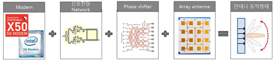
도 1은 일반적인 5G 차량용 안테나 시스템의 구성을 나타내는 도면이다. 도 1에 도시된 바와 같이 5G 차량용 안테나 시스템은 모뎀(Modem), 신호전달 네트워크, 페이저 쉬프터(Phase Shifter), 및 어레이 안테나(Array Antenna)로 구성된다. 일반적인 5G 차량용 안테나 시스템이 동작하는 경우, 도 2에 도시된 바와 같이 지향성 안테나인 어레이 안테나를 이용하여 4 섹션(Section) 빔 포밍(Beam Forming)을 통해 전방향성 신호를 구성한다. 이러한 경우, 빔 포밍을 위한 구성이 필요하여 시스템 구성이 복잡해지고 에러율이 높아질 뿐만 아니라, 통신을 수행하기 위한 빔 트래킹 과정에서 가장 강한 전파를 찾기 위하여 한 섹션(90°)당 최소 41 포인트(point)를 스캐닝(scanning) 해야 한다는 문제점이 있다.1 is a view showing the configuration of a typical 5G vehicle antenna system. As shown in FIG. 1, the 5G vehicle antenna system is composed of a modem, a signal transmission network, a phase shifter, and an array antenna. When a general 5G vehicle antenna system is operated, an omni-directional signal is configured through 4-section beam forming using an array antenna as a directional antenna as shown in FIG. 2. In this case, a configuration for beamforming is required, which complicates the system configuration and increases the error rate, and at least 41 points per section (90 °) to find the strongest radio wave in the beam tracking process for performing communication. There is a problem that must be scanned (scanning).
또한, 전방향 스캐닝을 위해서는 5G 차량용 안테나 시스템이 164 포인트를 스캐닝해야 하므로 시간지연이 발생한다는 문제점이 있다. In addition, there is a problem that time delay occurs because the 5G vehicle antenna system must scan 164 points for omnidirectional scanning.
또한, 일반적인 5G 차량용 안테나 시스템은 그 구성이 복잡하기 때문에 안테나 시스템의 제조비용이 증가할 수 밖에 없다.In addition, since the general 5G vehicle antenna system has a complicated configuration, the manufacturing cost of the antenna system is inevitably increased.
본 발명은 상술한 문제점을 해결하기 위한 것으로서, 수평면 상에 수직한 방향을 기준으로 미리 정해진 기준각도 범위 내에 신호를 전달할 수 있는 차량용 무지향성 안테나 장치를 제공하는 것을 그 기술적 특징으로 한다.The present invention is to solve the above-mentioned problems, and its technical feature is to provide a vehicle omni-directional antenna device capable of transmitting a signal within a predetermined reference angle range based on a vertical direction on a horizontal plane.
또한, 본 발명은 수평면 상에 전방향으로 신호를 전달할 수 있는 차량용 무지향성 안테나 장치를 제공하는 것을 그 기술적 특징으로 한다.In addition, the present invention is characterized in that it provides a vehicle omni-directional antenna device capable of transmitting signals in all directions on a horizontal plane.
또한, 본 발명은 빔 트래킹 과정 없이 5G 차량용 안테나 장치로 이용할 수 있는 차량용 무지향성 안테나 장치를 제공하는 것을 그 기술적 특징으로 한다.In addition, the present invention has a technical feature of providing a vehicle omni-directional antenna device that can be used as a 5G vehicle antenna device without a beam tracking process.
또한, 본 발명은 복수개의 디렉터 간의 길이를 5G 주파수대역인 6GHz(Sub 6) 또는 24GHz이상(mmWave)대의 전파는 파장이 짧고 감쇄가 크기 최적화된 차량용 무지향성 안테나 장치를 제공하는 것을 그 기술적 특징으로 한다.In addition, the present invention is to provide a vehicle omni-directional antenna device having a short wavelength and attenuation size optimized for propagation in a band of 6 GHz (Sub 6) or 24 GHz or more (mmWave), which is a 5G frequency band, between a plurality of directors. do.
상술한 목적을 달성하기 위한 본 발명의 일 측면에 따른 차량용 무지향성 안테나 장치는 수평면(X-Y) 상에 전방향으로 신호를 방사하는 바이커니컬 안테나(200); 상기 바이커니컬 안테나(200)로부터 일정한 거리로 이격되어 각각 배치된 복수개의 지지부재(250); 및 상기 각 지지부재(250)에 형성되고, 상기 바이커니컬 안테나(200)를 중심으로 수평면(X-Y) 상에 전방향으로 방사되는 신호 방향을 따라 서로 이격되어 위치하는 복수개의 디렉터(300)를 포함하는 것을 특징으로 한다.An omni-directional antenna device for a vehicle according to an aspect of the present invention for achieving the above object includes a
본 발명에 따르면 바이커니컬 안테나를 설치하고, 바이커니컬 안테나를 둘러싸는 복수개의 디렉터를 설치함으로써 수평면 상에 수직한 방향을 기준으로 미리 정해진 기준각도 범위 내에 신호를 전달할 수 있어5G 이동통신의 신호 송수신을 위한 최적의 각도 범위 내에서 신호를 송수신할 수 있다는 효과가 있다.According to the present invention, it is possible to transmit a signal within a predetermined reference angle range based on a vertical direction on a horizontal plane by installing a biconical antenna and installing a plurality of directors surrounding the biconical antenna. There is an effect that signals can be transmitted and received within an optimal angular range for transmission and reception.
또한, 본 발명은 바이커니컬 안테나를 이용함으로써 수평면 상에 전방향으로 신호를 전달할 수 있기 때문에 신호의 신뢰성이 향상될 뿐만 아니라, 신호 지연특성이 우수하다는 효과가 있다.In addition, since the present invention can transmit signals in all directions on a horizontal plane by using a biconical antenna, the signal reliability is improved, and the signal delay characteristics are excellent.
또한, 본 발명은 바이커니컬 안테나를 이용하기 때문에 5G 차량용 안테나 장치로 이용함에 있어 빔 트래킹 과정이 요구되지 않을 뿐만 아니라 이로 인해 시스템 구성이 단순하여 신호전달 시에 발생되는 손실이 낮고, 빔 트래킹을 위한 구성이 요구되지 않아 비용이 절감되는 효과가 있다.In addition, since the present invention uses a biconical antenna, a beam tracking process is not required in using as a 5G vehicle antenna device, and thus the system configuration is simple, resulting in low loss during signal transmission and beam tracking. There is an effect that the cost is reduced because no configuration is required.
또한, 본 발명은 5G 주파수대역인 6GHz(Sub 6) 또는 24GHz이상(mmWave)대의 전파의 특성인 파장이 짧고 감쇄가 큰 특성에 최적화되기 때문에, 차량용 5G 안테나 시스템에 적합하다는 효과가 있다.In addition, the present invention has an effect that it is suitable for a
도 1은 종래의 차량용 5G 안테나 시스템을 보여주는 도면이다.
도 2는 종래의 차량용 5G 안테나 시스템이 빔 트레킹을 통해 전방향성 신호를 구성하는 것을 보여주는 도면이다.
도 3a는 본 발명의 일 실시예에 따른 차량용 무지향성 안테나 장치를 보여주는 도면이다.
도 3b는 본 발명의 일 실시예에 따른 차량용 무지향성 안테나 장치의 분해도를 보여주는 도면이다.
도 4는 본 발명의 일 실시예에 따른 바이커니컬 안테나를 나타내는 도면이다.
도 5는 특정 주파수에서 바이커니컬 안테나의 간격에 따른 이득의 일예를 보여주는 표이다.
도 6은 복수개의 디렉터가 직선타입의 도전성 패턴으로 지지부재에 형성된 것의 일례를 보여주는 도면이다.
도 7a는 본 발명의 일 실시예에 따른 각 디렉터의 길이와 각 디렉터 간의 간격을 보여주는 도면이다.
도 7b는 본 발명의 일 실시예에 따른 각 디렉터의 길이와 각 디렉터 간의 간격을 보여주는 표이다.
도 8은 복수개의 디렉터가 곡선타입의 도전성 패턴으로 지지부재에 형성된 것의 일례를 보여주는 도면이다.
도 9a는 지지부재 상에 제1 도전성 패턴, 제2 도전성 패턴, 및 비아홀 라인이 형성된 것을 보여주는 사시도이다.
도 9b는 도 9a에 도시된 제1 도전성 패턴, 제2 도전성 패턴, 및 비아홀 라인이 형성된 지지부재(250)의 제1 단면(I-I')을 보여주는 도면이다.
도 9c는 도 9a에 도시된 제1 도전성 패턴, 제2 도전성 패턴, 및 비아홀 라인이 형성된 지지부재(250)의 제2 단면(II-II')을 보여주는 도면이다.
도 10a는 지지부재 상에 제1 도전성 패턴, 제2 도전성패턴, 및 복수개의 비아홀 라인이 형성된 것을 보여주는 사시도이다.
도 10b는 도 10a에 도시된 제1 도전성 패턴, 제2 도전성 패턴, 및 복수개의 비아홀 라인이 형성된 지지부재(250)의 제1 단면(I-I')을 보여주는 도면이다.
도 10c는 도 10a에 도시된 제1 도전성 패턴, 제2 도전성 패턴, 및 비아홀 라인이 형성된 지지부재(250)의 제2 단면(II-II')을 보여주는 도면이다.
도 11은 본 발명의 일 실시예에 따른 하우징에 형성된 홀을 보여주는 도면이다.
도 12a는 안테나 장치에 의해 형성되는 전계분포의 평면도의 일예를 나타내는 도면이다.
도 12b는 안테나 장치에 의해 형성되는 전계분포의 측면도의 일예를 나타내는 도면이다.
도 13은 안테나 장치가 차량에 설치되는 경우에 신호의 방사패턴을 보여주는 도면이다.1 is a view showing a
2 is a view showing a conventional 5G antenna system for a vehicle constructing an omni-directional signal through beam tracking.
3A is a view showing an omni-directional antenna device for a vehicle according to an embodiment of the present invention.
3B is an exploded view of an omni-directional antenna device for a vehicle according to an embodiment of the present invention.
4 is a view showing a biconical antenna according to an embodiment of the present invention.
5 is a table showing an example of gain according to the spacing of a biconical antenna at a specific frequency.
6 is a view showing an example of a plurality of directors formed on a support member in a straight conductive pattern.
7A is a diagram showing the length of each director and the interval between each director according to an embodiment of the present invention.
7B is a table showing the length of each director and the interval between each director according to an embodiment of the present invention.
8 is a view showing an example of a plurality of directors formed on a support member in a curved conductive pattern.
9A is a perspective view showing that a first conductive pattern, a second conductive pattern, and a via hole line are formed on a support member.
9B is a view showing a first cross-section (I-I ') of the
9C is a view showing a second cross section II-II 'of the
10A is a perspective view showing that a first conductive pattern, a second conductive pattern, and a plurality of via hole lines are formed on a support member.
FIG. 10B is a view showing a first cross-section (I-I ') of a
FIG. 10C is a view showing a second cross section II-II 'of the
11 is a view showing a hole formed in a housing according to an embodiment of the present invention.
12A is a diagram showing an example of a plan view of an electric field distribution formed by an antenna device.
12B is a view showing an example of a side view of an electric field distribution formed by an antenna device.
13 is a view showing a signal radiation pattern when the antenna device is installed in the vehicle.
이하, 첨부되는 도면을 참고하여 본 발명의 실시예들에 대해 상세히 설명한다.Hereinafter, embodiments of the present invention will be described in detail with reference to the accompanying drawings.
본 명세서에서 서술되는 용어의 의미는 다음과 같이 이해되어야 할 것이다.The meaning of the terms described in this specification should be understood as follows.
단수의 표현은 문맥상 명백하게 다르게 정의하지 않는 한 복수의 표현을 포함하는 것으로 이해되어야 하고, "제1", "제2" 등의 용어는 하나의 구성요소를 다른 구성요소로부터 구별하기 위한 것으로, 이들 용어들에 의해 권리범위가 한정되어서는 아니 된다.It should be understood that a singular expression includes a plurality of expressions unless the context clearly defines otherwise, and the terms "first", "second", etc. are intended to distinguish one component from another component, The scope of rights should not be limited by these terms.
"포함하다" 또는 "가지다" 등의 용어는 하나 또는 그 이상의 다른 특징이나 숫자, 단계, 동작, 구성요소, 부분품 또는 이들을 조합한 것들의 존재 또는 부가 가능성을 미리 배제하지 않는 것으로 이해되어야 한다.It should be understood that terms such as “include” or “have” do not preclude the existence or addition possibility of one or more other features or numbers, steps, actions, components, parts or combinations thereof.
"적어도 하나"의 용어는 하나 이상의 관련 항목으로부터 제시 가능한 모든 조합을 포함하는 것으로 이해되어야 한다. 예를 들어, "제1 항목, 제2 항목 및 제 3항목 중에서 적어도 하나"의 의미는 제1 항목, 제2 항목 또는 제3 항목 각각 뿐만 아니라 제1 항목, 제2 항목 및 제3 항목 중에서 2개 이상으로부터 제시될 수 있는 모든 항목의 조합을 의미한다.It should be understood that the term “at least one” includes all possible combinations from one or more related items. For example, the meaning of “at least one of the first item, the second item, and the third item” means 2 of the first item, the second item, and the third item, as well as each of the first item, the second item, and the third item. Any combination of items that can be presented from more than one dog.
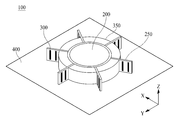
도 3a는 본 발명의 일 실시예에 따른 차량용 무지향성 안테나 장치(이하 '안테나 장치'라 함)를 보여주는 도면이고, 도 3b는 본 발명의 일 실시예에 따른 안테나 장치의 분해도를 보여주는 도면이다.3A is a view showing an omni-directional antenna device for a vehicle (hereinafter referred to as an 'antenna device') according to an embodiment of the present invention, and FIG. 3B is an exploded view of an antenna device according to an embodiment of the present invention.
본 발명에 따른 안테나 장치(100)는 바이커니컬 안테나(Biconical Antenna, 200), 복수개의 지지부재(Printed Ciruit Board, 250), 복수개의 디렉터(Director)(300), 하우징(350), 및 그라운드 플레이트(400)를 포함한다.The
바이커니컬 안테나(200)는 수평면(X-Y) 상에 전 방향으로 신호를 방사한다. 이때, 바이커니컬 안테나(200)는 수평면(X-Y)에 대해 수직인 전계를 형성하여 수직편파인 신호를 방사할 수 있다.The
본 발명은 바이커니컬 안테나(200)가 신호를 수평면(X-Y) 상에 전 방향으로 신호를 방사하기 때문에 일반적인 5G 차량용 안테나와 달리 빔 트래킹을 수행할 필요가 없어 빔 트래킹을 위한 구성이 필요없을 뿐만 아니라, 빔 트래킹 과정에서 발생되는 신호 손실이 낮아 신호의 신뢰성이 향상된다는 효과가 있다.In the present invention, since the
더욱이, 본 발명은 빔 트래킹을 위한 구성이 필요없기 때문에 기존 5G 차량용 안테나에 비해 비용절감 효과가 발생한다는 효과가 있다.Moreover, the present invention has an effect that a cost reduction effect is generated compared to an existing 5G vehicle antenna because no configuration for beam tracking is required.
일 실시예에 있어서, 바이커니컬 안테나(200)는 반파장 안테나일 수 있다. 이러한 실시예를 따를 때 바이커니컬 안테나의 높이는 ![]()
![]()
일 실시예에 있어서, 바이커니컬 안테나(200)의 특성임피던스는 아래의 수학식 1에 따라 산출될 수 있다. In one embodiment, the characteristic impedance of the

이때 ![]()
![]()
![]()
![]()
상술한 실시예와 달리 안테나의 특성 임피던스가 설정된 경우 수학식1에 따라 바이커니컬 안테나(200)의 중심각(![]()
![]()
![]()
![]()
![]()
![]()
일 실시예에 있어서, 바이커니컬 안테나(200)의 입력 임피던스는 아래의 수학식 2에 따라 산출될 수 있다. In one embodiment, the input impedance of the

이때, ![]()
![]()
![]()
![]()
이때, ![]()
![]()

이때 ![]()
![]()
![]()
![]()
또한 ![]()
![]()
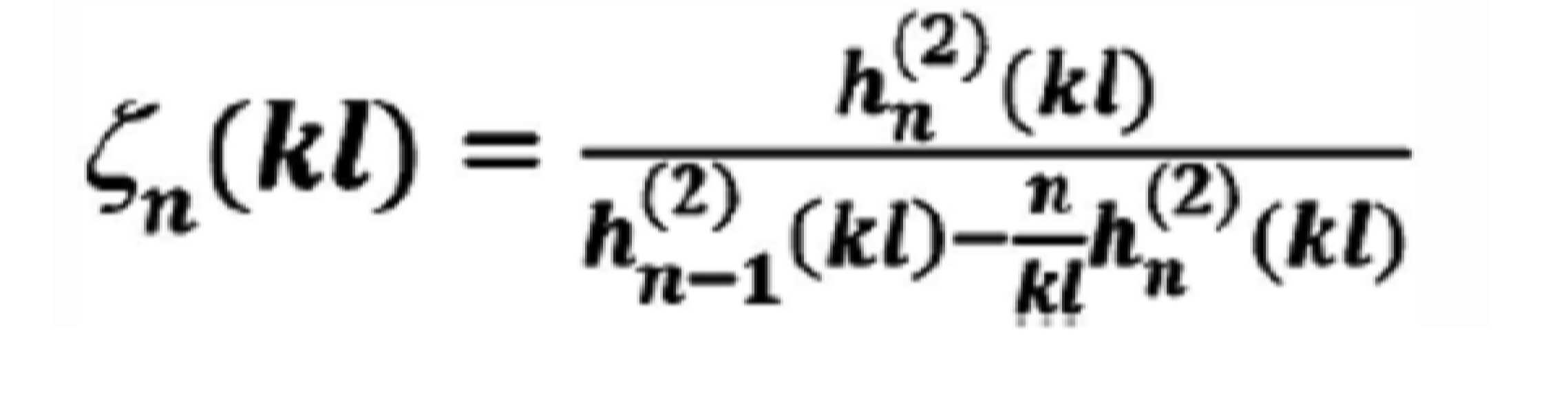
이때, k는 파장상수를 의미하고 l은 바이커니컬 안테나(200)의 빗변을 의미한다.At this time, k is a wavelength constant and l is a hypotenuse of the
이하, 도 4를 참조하여 본 발명에 따른 바이커니컬 안테나(200)를 보다 구체적으로 설명한다.Hereinafter, a
도 4는 본 발명의 일 실시예에 따른 바이커니컬 안테나를 나타내는 도면이다.4 is a view showing a biconical antenna according to an embodiment of the present invention.
바이커니컬 안테나(200)는 제1 커니컬(210), 제2 커니컬(212), 및 피딩부(214)를 포함한다.The
제1 커니컬(210)은 피딩부(214)로부터 전원을 공급받아 제2 커니컬(212)과의 전위차에 따라 전계를 형성하여 수평면(X-Y)상에 신호가 전방향으로 방사될 수 있도록 한다. The
제1 커니컬(210)은 원추형으로 형성되고, 제1 커니컬(210)의 아랫단에 피딩부(214)가 연결되는 연결홈이 형성된다. The
제2 커니컬(212)은 그라운드 플레이트(400)에 연결되어 제1 커니컬(210)과 전계를 형성하여 수평면(X-Y)상에 신호가 전방향으로 방사될 수 있도록 한다. 이러한 실시예를 따를때, 그라운드 플레이트(400)는 접지(Ground)일 수 있다. 이에 따라 제2 커니컬(212)은 전위를 0으로 유지하게 되어 제1 커니컬(210)과의 전위차에 따라 전계가 형성되어 신호를 수평면(X-Y)상에 전방향으로 방사될 수 있게 할 수 있다.The
제2 커니컬(212)은 원추형으로 형성되어 윗단에 피딩부(214)가 통과하는 투과공이 형성된다. 이때, 제2 커니컬(212)의 투과공은 피딩부(214)과 통과하기 위해 제1 커니컬의 연결홈보다 크게 형성될 수 있다. The
일 실시예에 있어서 제2 커니컬(212)의 투과공은 피딩부(214)를 고정시키기 위해 고정부재가 형성될 수 있다. 이때, 고정부재는 유전체로 형성될 수 있다. In one embodiment, the transmission hole of the
일 실시예에 있어서, 제1 커니컬 및 제2 커니컬(210, 212)의 빗변 길이는 아래의 수학식 5에 따라 산출될 수 있다.In one embodiment, the hypotenuse lengths of the first and
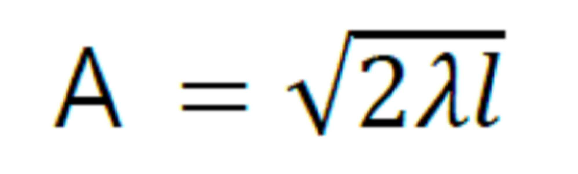
이때, A는 바이커니컬 안테나(200)의 높이를 의미하고, λ는 신호의 파장길이를 의미하고, l은 빗변 길이를 의미할 수 있다. At this time, A means the height of the
예컨대, 바이커니컬 안테나(200)의 높이가 ![]()
![]()
![]()
![]()
일 실시예에 있어서, 제1 커니컬 및 제2 커니컬(210, 212)의 간격(G)은 0.1mm 내지 2mm 내일 수 있다. 일례로, 제1 커니컬 및 제2 커니컬(210, 212)의 간격(G)은 최대 이득을 갖는 길이로 설정될 수 있다.In one embodiment, the spacing G between the first and
예컨대, 도 5에 도시된 바와 같이 제1 커니컬 및 제2 커니컬(210, 212)의 간격(G)은 주파수가 28GHz일 때 최대 이득을 갖는 0.75mm로 설정될 수 있다. For example, as illustrated in FIG. 5, the spacing G between the first and
일 실시예에 있어서, 제1 커니컬 및 제2 커니컬(210, 212)은 구리(Cu)로 형성될 수 있다.In one embodiment, the first and
피딩부(214)는 제1 커니컬(210)로 전원을 공급하여 급전한다. 구체적으로 피딩부(214)는 제2 커니컬(212)의 투과공을 통과하여 제1 커니컬(210)의 연결홈에 연결되어 제1 커니컬(210)로 전원을 공급하여 급전할 수 있다. The
다시 도 3a 및 3b를 참조하면 복수개의 지지부재(250)는 바이커니컬 안테나(200)를 중심으로 일정한 거리로 이격되어 각각 배치될 수 있다. 이때, 복수개의 지지부재(250)의 하단이 그라운드 플레이트(400)에 결합되어 복수개의 지지부재(250)는 수평면(X-Y)에 대해 수직한 제1 방향(Z)으로 설치되게 된다. 일 실시예에 있어서, 복수개의 지지부재(250)는 PCB(Printed Circuit Board)일 수 있다.Referring back to FIGS. 3A and 3B, the plurality of
복수개의 지지부재(250)는 하우징(350)에 결합될 수 있다. 구체적으로 복수개의 지지부재(250)는 하우징(350)에 형성된 결합홈에 결합될 수 있다. 이에 따라 복수개의 지지부재(250)는 하우징(350)에 의해 지지력이 향상될 수 있다.The plurality of
복수개의 디렉터(300)는 각 지지부재(250)에 형성된다. 복수개의 디렉터(300)는 각 지지부재(250) 상에 바이커니컬 안테나(200)를 중심으로 수평면(X-Y)상에 전방향으로 신호 방향의 가상의 직선을 따라 서로 이격되어 위치한다.A plurality of
복수개의 디렉터(300)는 바이커니컬 안테나(200)가 방사되는 신호가 수직면 상에서 방사되는 방향을 미리 정해진 기준각도 내의 방향으로 지향시킬 수 있다. The plurality of
일례로, 복수개의 디렉터(300)는 수평면(X-Y)에 대해 수직한 제1 방향(Z)을 기준으로 60° 내지 90°로 신호를 지향시킬 수 있다. For example, the plurality of
일 실시예에 있어서, 복수개의 디렉터(300)는 그라운드 플레이트(400)에 의해 제1 방향(Z)으로 반사되는 신호를 미리 정해진 기준각도의 방향으로 지향시킬 수 있다. 이러한 실시예를 따를 때, 본 발명에 따른 복수개의 디렉터(300)는 미리 정해진 각도 내의 신호의 지향성이 향상시킬 수 있을 뿐만 아니라 그라운드 플레이트(400)에 의해 제1 방향(Z)으로 반사되어 손실되는 신호를 감소시켜 송수신 감도를 향상시킬 수 있다.In one embodiment, the plurality of
이에 따라 본 발명은 5G 이동 통신 시스템의 신호를 차량에서 송신 또는 수신하기 위한 최적의 각도범위 내에서 신호를 송신 또는 수신할 수 있다.Accordingly, the present invention can transmit or receive a signal within an optimal angular range for transmitting or receiving a signal from a 5G mobile communication system.
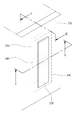
일 실시예에 있어서 복수개의 디렉터(300)는 수평면(X-Y)에 대해 수직한 제1 방향(Z)으로 연장형성된 직선 타입의 도전성 패턴일 수 있다. 예컨대, 도 6에 도시된 바와 같이 복수개의 디렉터(300)는 지지부재(250) 상에 수평면(X-Y))에 대해 수직한 제1 방향(Z)으로 연장되어 형성된 직선 타입의 도전성 패턴일 수 있다. In one embodiment, the plurality of
도 6에서는 복수개의 디렉터(300)가 4개인 것으로 도시하였으나, 이는 하나의 예 일뿐, 3개 이하일 수 있고 5개 이상일 수 도 있다. In FIG. 6, the plurality of
일 실시예에 있어서 복수개의 디렉터(300)의 길이는 각 디렉터 별로 설정된 제1 계수와 바이커니컬 안테나(200)에 의해 방사되는 신호의 파장길이의 곱셈으로 정해질 수 있다. 이때, 제1 계수는 복수개의 디렉터(300) 중 적어도 하나가 다를 수 있다.In one embodiment, the length of the plurality of
일 실시예에 있어서, 복수개의 디렉터(300)의 길이는 바이커니컬 안테나(200)로부터 멀어질 수록 짧게 형성될 수 있다. 디렉터(300)의 길이가 중요한데, 디렉터(300)가 바이커니컬 안테나(200)의 높이 보다 길게 설정될 경우, 디렉터(300)는 연장코일로 동작된다. 디렉터(300)가 코일로 동작하게 되어 인덕턴스성을 가지게 되면 전기적 길이가 바이커니컬 안테나(200)보다 길어져, 반사기로 동작을 하게 된다. 반면에, 디렉터(300)가 바이커니컬 안테나(200)의 높이보다 짧게 설정되면, 디렉터(300)는 캐패시터로 동작된다. 디렉터(300)가 캐패시터로 동작하게 되어 디렉터(300)는 정전용량성을 가져 전기적 길이가 바이커니컬 안테나(200)보다 짧아져, 반사기로 동작하지 않고 도파기로 작동하여 전파를 유도하게 된다.In one embodiment, the length of the plurality of
본 발명에 따른 복수개의 디렉터(300)의 길이가 바이커니컬 안테나(200)로부터 멀어질 수록 짧게 형성되는 이유는, 각 디렉터로 신호가 전달될 때 순차적으로 에너지가 감쇄되기 때문에 동일한 길이로 디렉터가 형성되면 감소된 에너지가 전달됨에 따라 점차적으로 신호 전달 효율이 낮아지기 때문이다.The reason that the lengths of the plurality of
특히, 5G 주파수 대역의 신호는 파장이 짧아 신호 감쇄가 크므로, 신호 감쇄를 고려하여 기존의 안테나 설계에서 고려하지 않았던 미세한 부분까지 고려하여 설계된 것이다.In particular, since the signal in the 5G frequency band has a short wavelength and has large signal attenuation, it is designed in consideration of signal attenuation and even a minute portion not considered in the conventional antenna design.
일례로, 도 7a에 도시된 바와 같이 복수개의 디렉터(300)는 제1 디렉터(310a), 제2 디렉터(310b), 제3 디렉터(310c), 제4 디렉터(310d), 및 제5 디렉터(310e)를 포함할 수 있다. 이때, 제1 내지 제5 디렉터(310a-310e)는 순차적으로 바이커니컬 안테나로부터 이격되어 위치한다. 따라서, 제1 디렉터(310a)가 바이커니컬 안테나로부터 가장 가깝게 위치하고, 제5 디렉터(310e)가 바이커니컬 안테나로부터 가장 멀리 위치하게 된다.For example, as illustrated in FIG. 7A, the plurality of
이러한 예를 따를 때, 제1 내지 제5 디렉터(310a-310e)는 순차적으로 길이가 짧아질 수 있다.When following this example, the first to
예컨대, 제1 내지 제5 디렉터(310a-310e)의 길이(L1-L5)는 도 7b에 도시된 바와 같이 설정될 수 있다. 구체적으로 제1 디렉터(310a)의 길이(L1)는 0.45λ로 설정하고, 제2 디렉터(310b)의 길이(L2)는 0.44λ로 설정하며, 제3 디렉터(310c)의 길이(L3)는 0.43λ로 설정하고, 제4 디렉터(310d)의 길이(L4)는 0.4λ로 설정하며, 제5 디렉터(310e)의 길이(L5)는 0.32λ로 설정할 수 있다. 이때, λ는 신호의 파장길이를 의미한다.For example, the lengths L1-L5 of the first to
다만, 본 발명의 일예에 따른 제1 디렉터(310a)와 제2 디렉터(310b)의 길이는 동일하게 형성될 수도 있다.However, the lengths of the
본 발명의 일예에 따른 제1 디렉터(310a)와 제2 디렉터(310b)의 길이가 동일하게 형성될 수 있는 이유는, 제1 디렉터(310a) 및 제2 디렉터(310b)가 바이커니컬 안테나(200)와 가깝게 위치하여 바이커니컬 안테나(200)로부터 방사되는 신호의 에너지가 크기 때문에 제1 디렉터(310a) 및 제2 디렉터(310b)의 길이가 동일하게 형성되더라도, 신호 감쇄를 무시할 수 있기 때문이다. The reason that the lengths of the
이러한 예를 따를때, 각 디렉터(310a-310e)의 길이는 L1>L2>L3>L4>L5 또는 L1=L2>L3>L4>L5로 형성될 수 있다.When following this example, the length of each
한편, 복수개의 디렉터(300)는 각 지지부재(250) 상에 형성되어 바이커니컬 안테나(200)으로부터 외곽방향으로 이격되어 배치되게 된다.On the other hand, a plurality of
복수개의 디렉터(300)간의 간격은 각 디렉터 별로 설정된 제2 계수와 신호의 파장길이의 곱셈으로 정해질 수 있다.The interval between the plurality of
일 실시예에 있어서, 복수개의 디렉터(300) 중 바이커니컬 안테나(200)와 가장 가까운 디렉터(300)는 바이커니컬 안테나(200)로부터 방사되는 신호의 에너지가 최대로 되는 지점에 위치할 수 있다. 이때, 신호의 에너지가 최대로 되는 지점은 제1 커니컬(210)의 최상단 또는 제2 커니컬(212)의 최하단을 기준으로 방사되는 신호의 0.25λ만큼 이격된 위치일 수 있다.In one embodiment, among the plurality of
예컨대, 도 7a 및 7b에 도시된 바와 같이 제1 디렉터(310a)와 바이커니컬 안테나(200)간의 간격(Y)은 0.25λ일 수 있다. For example, as illustrated in FIGS. 7A and 7B, an interval Y between the
본 발명에 따른 제1 디렉터(310a)가 바이커니컬 안테나(200)로부터0.25λ만큼 이격된 이유는, 0.25λ는 하나의 파장 내에 에너지가 최대가 되는 지점이기 때문에, 신호가 제1 디렉터(310a)로 전달될 때 에너지 전달 효율이 가장 크기 때문이다. The reason that the
복수개의 디렉터(300)간에는 신호가 각 디렉터를 통과함에 따라 지연되는 파장의 길이만큼 보상하여 이격될 수도 있다. 일례로, 도 7a 내지 7b에 도시된 바와 같이 제1 내지 제5 디렉터(310a-310e)간의 간격(X1-X4)은 0.31λ로 설정될 수 있다. 구체적으로 제 1 디렉터(310a)와 제2 디렉터(310b)간의 간격(X1)은 0.31λ이고, 제2 디렉터(310b)와 제3 디렉터(310c)간의 간격(X2)은 0.31λ이며, 제3 디렉터(310c)와 제4 디렉터(310d)간의 간격(X3)은 0.31λ이고, 제4 디렉터(310d)와 제5 디렉터(310e)간의 간격(X4)은 0.31λ이다. A plurality of
이러한 예를 따를때, 바이커니컬 안테나(200)와 제1 디렉터(310a)간의 간격(Y)이 복수개의 디렉터(310a-310e)간의 간격(X1-X4)보다 좁을 수 있다(Y<X1=X2=X3=X4).When following this example, the spacing Y between the
이와 같이 본 발명은 각 디렉터를 통과함에 따라 지연되는 파장의 길이만큼 보상하여 신호의 에너지가 최대가 되는 지점에 각 디렉터를 위치시키기 때문에, 에너지 전달 효율을 극대화시킬 수 있다는 효과가 있다.As described above, according to the present invention, since each director is positioned at the point where the energy of the signal is maximized by compensating for the length of the delayed wavelength as it passes through each director, it is possible to maximize energy transfer efficiency.
일 실시예에 있어서, 복수개의 디렉터(300)는 미리 정해진 곡률로 바이커니컬 안테나(200) 측으로 휘어져 형성된 곡선타입의 도전성 패턴일 수 있다. 일례로, 복수개의 디렉터(300)은 각 디렉터(300)의 상측이 바이커니컬 안테나(200)측으로 휘어져 형성될 수 있다. In one embodiment, the plurality of
예컨대, 도 8에 도시된 바와 같이 복수개의 디렉터(300)의 상측이 미리 정해진 곡률로 바이커니컬 안테나(200) 측으로 휘어져 형성될 수 있다. For example, as illustrated in FIG. 8, the upper sides of the plurality of
도 8에 도시된 일례와 다른 예로써 복수개의 디렉터(300)는 각 디렉터(300)의 하측이 미리 정해진 곡률로 바이커니컬 안테나(200)측으로 휘어져 형성될 수 있다.As an example different from the example illustrated in FIG. 8, the plurality of
도 8에 도시된 일례와 또 다른 예로써 복수개의 디렉터(300)는 각 디렉터(300)의 상측 및 하측이 미리 정해진 곡률로 바이커니컬 안테나(200)측으로 휘어져 형성될 수 있다.As another example and another example illustrated in FIG. 8, the plurality of
본 발명에 따른 복수개의 디렉터(300)가 미리 정해진 곡률로 휘어져 형성된 곡선타입의 도전성 패턴으로 구성되는 이유는, 각 디렉터를 신호의 파장형태와 동일하게 곡선형태로 구현함으로써 디렉터로 전달되면서 발생하는 신호의 위상차를 감소시키기 위함이다. 특히, 5G 주파수 대역의 신호 특성상 감쇄가 크고, 회절성이 낮기 때문에 기존의 안테나 설계에서 고려하지 않았던, 미세한 부분까지 고려하여 설계된 것이다.The reason why the plurality of
이에 따라 본 발명은 복수개의 디렉터(300)가 미리 정해진 곡률로 휘어져 형성된 곡선타입의 도전성 패턴으로 구성됨으로써 각 디렉터로 전달되면서 발생하는 신호의 위상차를 감소시킬 수 있어 안테나 효율을 상승시킬 수 있다. Accordingly, according to the present invention, since a plurality of
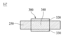
일 실시예에 있어서, 각 디렉터(300)는 제1 도전성 패턴, 제2 도전성 패턴, 및 비아홀 라인을 포함할 수 있다. 여기서, 제1 도전성 패턴은 지지부재(250)의 일면에 형성될 수 있고, 제2 도전성 패턴은 지지부재(250)의 타면에 형성될 수 있으며, 비아홀 라인은 제1 도전성 패턴 및 제2 도전성패턴을 연결시킬 수 있다. 이때, 제2 도전성 패턴은 제1 도전성 패턴이 형성된 영역에 대응되는 영역에 형성될 수 있다.In one embodiment, each
이러한 실시예를 따를 때 각 디렉터(300)가 형성되는 지지부재(250)는 다중 레이어를 포함하는 멀티 레이어 PCB(Multi Layer Printed Circuit Board)일 수 있다.When following this embodiment, the
일 실시예에 있어서, 제1 및 제2 도전성 패턴은 직선타입의 도전성 패턴일 수 있고, 다른 실시예에 있어서, 제1 및 제2 도전성 패턴은 곡선타입의 도전성 패턴일 수 있다.In one embodiment, the first and second conductive patterns may be straight-type conductive patterns, and in other embodiments, the first and second conductive patterns may be curved-type conductive patterns.
이하 도 9를 참조하여 각 디렉터(300)가 제1 도전성 패턴, 제2 도전성 패턴 및 비아홀 라인을 포함하는 경우를 보다 더 구체적으로 설명한다.Hereinafter, a case in which each
도 9는 각 디렉터(300)가 제1 도전성 패턴, 제2 도전성 패턴, 및 비아홀 라인을 포함하는 경우의 일례를 보여주는 도면이다. 도 9에서는 설명의 편의를 위해 지지부재(250) 상에 하나의 디렉터(300)가 형성된 것으로 도시하였다.9 is a diagram illustrating an example in which each
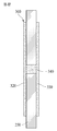
도 9a는 지지부재 상에 제1 도전성 패턴, 제2 도전성 패턴, 및 비아홀 라인이 형성된 것을 보여주는 사시도이다. 9A is a perspective view showing that a first conductive pattern, a second conductive pattern, and a via hole line are formed on a support member.
도 9a에 도시된 바와 같이 제1 도전성 패턴(320)은 지지부재(250)의 일면상에 형성되고, 제2 도전성 패턴(330)은 제1 도전성 패턴(320)이 형성된 영역에 대응되는 지지부재(250)의 타면상에 형성될 수 있다. 비아홀 라인(340)은 제1 도전성 패턴(320) 및 제2 도전성 패턴(330)을 연결시킨다.9A, the first
이와 같이 본 발명에 따른 제1 도전성 패턴(320) 및 제2 도전성 패턴이 비아홀 라인(340)으로 연결되는 이유는 전체적으로 하나의 도전성패턴을 이루게 하여 하나의 디렉터(300)로 동작될 수 있게 하기 위함이다.As such, the reason that the first
각 디렉터(300)가 제1 도전성 패턴(320), 제2 도전성 패턴(330), 및 비아홀 라인(340)로 구성될 경우, 도 9b 및 도 9c에 도시된 바와 같은 단면으로 각 디렉터(300)가 형성될 수 있다. When each
도 9b는 도 9a에 도시된 제1 도전성 패턴, 제2 도전성 패턴, 및 비아홀 라인이 형성된 지지부재(250)의 제1 단면(I-I')을 보여주는 도면이다. 도 9c는 도 9a에 도시된 제1 도전성 패턴, 제2 도전성 패턴, 및 비아홀 라인이 형성된 지지부재(250)의 제2 단면(II-II')을 보여주는 도면이다.FIG. 9B is a view showing a first cross-section (I-I ') of the
도 9a 내지 도 9c에서 비아홀 라인(340)이 제1 도전성 패턴(320) 및 제2 도전성 패턴(330)의 중앙에 형성된 것으로 도시하였으나, 이는 하나의 예일 뿐 비아홀 라인(340)은 제1 도전성 패턴(320) 및 제2 도전성 패턴(330)의 상측에 형성될 수도 있고, 제1 도전성 패턴(320) 및 제2 도전성 패턴(330)의 하측에 형성될 수도 있다.9A to 9C, the via
또한, 도 9a 내지 도 9c에서 제1 도전성 패턴(320) 및 제2 도전성 패턴(330)이 직선타입의 도전성 패턴으로 도시하였으나, 이는 하나의 예일 뿐, 제1 도전성 패턴(320) 및 제2 도전성 패턴(330)이 곡선타입의 도전성 패턴으로 구성될 수도 있다. In addition, in FIGS. 9A to 9C, the first
상술한 실시예에서는 비아홀 라인(340)이 하나인 것으로 설명하였다. 하지만, 변형된 실시예에 있어서, 비아홀 라인(340)은 복수개일 수 있다. 이러한 실시예를 따르는 경우, 지지부재(250)에는 복수개의 비아홀이 형성되어 있고, 복수개의 비아홀 라인(340)이 복수개의 비아홀을 통해 제1 도전성 패턴(320) 및 제2 도전성 패턴(330)을 연결시킬 수 있다.In the above-described embodiment, it has been described that the via
이하 변형된 실시예에 대해 도 10a 내지 10c를 참조하여 보다 구체적으로 설명한다. Hereinafter, a modified embodiment will be described in more detail with reference to FIGS. 10A to 10C.
도 10a는 지지부재 상에 제1 도전성 패턴, 제2 도전성패턴, 및 복수개의 비아홀 라인이 형성된 것을 보여주는 사시도이다.10A is a perspective view showing that a first conductive pattern, a second conductive pattern, and a plurality of via hole lines are formed on a support member.
도 10a에 도시된 바와 같이 제1 도전성 패턴(320)은 지지부재(250)의 일면상에 형성되고, 제1 도전성 패턴(330)은 제1 도전성 패턴(320)이 형성된 영역에 대응되는 지지부재(250)의 타면상에 형성될 수 있다. 여기서 복수개의 비아홀 라인(340)은 제1 도전성 패턴(320) 및 제2 도전성 패턴(330)을 연결시킨다. 이러한 경우, 제1 도전성 패턴(320), 제2 도전성 패턴(330), 및 복수개의 비아홀 라인(340)은 막대형태의 디렉터(300)를 형성하게 된다. 10A, the first
이는 제1 도전성 패턴(320), 제2 도전성 패턴, 복수개의 비아홀 라인(340)이 전체적으로 하나의 도전성패턴을 이루게 하여 하나의 디렉터(300)로 동작될 수 있게 하기 위함이다. This is to enable the first
이와 같이 각 디렉터(300)가 제1 도전성 패턴(320), 제2 도전성 패턴(330), 및 복수개의 비아홀 라인(340)로 구성될 경우, 도 10b 및 도 10c에 도시된 바와 같은 단면으로 각 디렉터(300)가 형성될 수 있다.As described above, when each
도 10b는 도 10a에 도시된 제1 도전성 패턴, 제2 도전성 패턴, 및 복수개의 비아홀 라인이 형성된 지지부재(250)의 제1 단면(I-I')을 보여주는 도면이다. 도 10c는 도 10a에 도시된 제1 도전성 패턴, 제2 도전성 패턴, 및 비아홀 라인이 형성된 지지부재(250)의 제2 단면(II-II')을 보여주는 도면이다.FIG. 10B is a view showing a first cross-section (I-I ') of a
이와 같이 제1 도전성 패턴(320), 제2 도전성 패턴(330), 및 복수개의 비아홀 라인(340)은 막대형태의 디렉터(300)를 형성하게 된다.As such, the first
다시 도 3a 및 3b를 참조하면, 하우징(350)은 바이커니컬 안테나를 감싸는 형태로 형성되어 복수개의 지지부재(250)가 결합된다. 이를 위해 하우징(350)은 복수개의 지지부재(250)가 결합되기 위한 복수개의 결합홈이 형성될 수 있다. Referring back to Figures 3a and 3b, the
이에 따라 하우징(350)에 형성된 복수개의 결합홈에 복수개의 지지부재(250)가 결합됨으로써 복수개의 지지부재(250)의 고정력이 향상된다는 효과가 있다.Accordingly, a plurality of
일 실시예에 있어서, 하우징(350)은 유전체일 수 있다. 이러한 실시예를 따를 경우, 하우징(350)을 통과하는 신호의 파장길이가 짧아지게 되어 안테나 장치(100)를 소형화시킬 수 있다. 이때, 유전율은 4이하이면서 로스 탄젠트(Loss Tangent)가 0.02 이하인 것이 바람직하다.In one embodiment, the
일 실시예에 있어서, 하우징(350)은 적어도 하나 이상의 홀이 형성될 수 있다. 이러한 실시예를 따를때, 적어도 하나의 홀을 통해 바이커니컬 안테나(200)가 공기와 접촉될 수 있다.In one embodiment, the
도 11은 본 발명의 일 실시예에 따른 하우징(350)에 형성된 홀을 보여주는 도면이다. 하우징(350)에 형성된 홀(360)은 바이커니컬 안테나(200)가 공기와 접촉할 수 있게 하여 바이커니컬 안테나(200)가 공기를 통해 신호 방사를 할 수 있도록 한다.11 is a view showing a hole formed in the
도 11에서는 하우징(350)에 하나의 홀(360)이 형성된 것으로 도시하였으나 이는 하나의 예일 뿐 홀(360)은 두개 이상 형성될 수도 있다.In FIG. 11, one
하우징(350)은 바이커니컬 안테나(210)의 제1 커니컬(210)이 실장되게 원추형으로 형성된 원추형 홈이 하우징(350)의 중앙 상측에 형성되고, 바이커니컬 안테나(210)의 제2 커니컬(210)이 실장되게 뒤집어진 원추형 형태로 형성된 원추형 홈이 하우징(350)의 중앙 하측에 형성된다.In the
하우징(350)의 중앙에는 바이커니컬 안테나(210)의 피딩부(214)가 통과할 수 있게 관통홀이 형성되고, 이에 따라 제2 커니컬(212)을 통과한 피딩부(214)가 관통홀을 통과하여 제1 커니컬(210)에 연결될 수 있게 된다.A through hole is formed in the center of the
하우징(350)의 하측에는 그라운드 플레이트(400)에 고정되기 위한 복수개의 고정홈이 형성되고, 고정홈에는 그라운드 플레이트(400)로부터 고정부재가 삽입되어 하우징(350)이 그라운드 플레이트(400)에 고정되게 된다.A plurality of fixing grooves for fixing to the
하우징(350)은 바이커니컬 안테나(200)의 제1 커니컬(210)이 고정되게 하우징 덮개를 더 포함한다. 하우징 덮개에는 하우징(350)과 고정되기 위한 복수개의 고정홀이 형성되고, 하우징(350)의 상측에는 하우징 덮개를 고정시기 위한 복수개의 고정홈이 형성된다. 이에 따라 고정부재가 고정홀을 통과하여 고정홈에 삽입되어 하우징 덮개가 하우징(350)에 고정되고, 바이커니컬 안테나(200)의 제1 커니컬(212)이 고정되게 된다. The
그라운드 플레이트(400)은 바이커니컬 안테나(200)의 하측에 결합되어 바이커니컬 안테나(200)를 지지한다. 그라운드 플레이트(400)는 복수개의 지지부재(250)가 바이커니컬 안테나(200)를 중심으로 결합된다. 이를 위해 그라운드 플레이트(400)에는 복수개의 지지부재(250)가 결합되기 위한 복수개의 결합홈이 형성되고, 복수개의 결합홈은 바이커니컬 안테나를 중심으로 형성되어 있다.The
그라운드 플레이트(400)는 하우징(350)을 고정시키기 위한 복수개의 고정홀이 형성되고, 복수개의 고정홀에는 고정부재가 통과하게 되어 하우징(350)이 고정되게 된다. The
그라운드 플레이트(400)는 바이커니컬 안테나(200)에서 방사되는 신호를 그라운드 플레이트(400)에 수직한 제1 방향(Z)으로 반사시키게 된다. 이때, 본 발명에 따른 복수개의 디렉터(300)가 그라운드 플레이트(400)에 반사되는 신호를 미리 정해진 기준각도로 신호를 지향시키게 된다.The
일례로, 그라운드 플레이트(400)는 바이커니컬 안테나(200)에서 방사되는 신호를 반사시키게 되고, 복수개의 디렉터(250)가 반사된 신호를 수평면(X-Y)에 대해 수직한 제1 방향(Z)을 기준으로 60° 내지 90°로 지향시키게 된다. 5G 주파수 대역은 고주파수이기 때문에 파장이 짧아, 저주파수 대역대에 비하여 그라운드 플레이트에 의해 반사되는 경향이 많다. 이에 따라 본 발명에 따른 복수개의 디렉터(300)는 그라운드 플레이트에 의해 반사되어 수평면(X-Y)에 수직한 제1 방향(Z)을 기준으로 30° 내지 60°로 상방으로 향하는 전파를 수평면(X-Y)에 대해 수직한 제1 방향(Z)을 기준으로 60° 내지 90°로 지향시키게 된다. For example, the
본 발명에 따른 안테나 장치(100)는 도 12a 및 12b에 도시된 바와 같이 전계분포를 형성할 수 있다. 도 12a는 안테나 장치(100)에 의해 형성되는 전계분포의 평면도의 일예를 나타내는 도면이고, 도 12b는 안테나 장치(100)에 의해 형성되는 전계분포의 측면도의 일예를 나타내는 도면이다.The
도 12a에 도시된 바와 같이 바이커니컬 안테나(200)에 의해 수평면(X-Y) 상에 전방향으로 신호가 방사되고, 도 12b에 도시된 바와 바이커니컬 안테나(200)에 의해 방사된 신호가 그라운드 플레이트(400)에 의해 반사되어 복수개의 디렉터(250)에 의해 수평면(X-Y)에 대해 수직한 제1 방향(Z)을 기준으로 60° 내지 90°로 지향되게 된다.As shown in FIG. 12A, the signal is radiated in all directions on the horizontal plane XY by the
일반적으로 5G 차량용 안테나의 경우 수평면(X-Y)에 대해 수직한 제1 방향(Z)을 기준으로 60° 내지 90°에서 신호가 유효하게 송수신된다. 이에 따라 본 발명은 수평면(X-Y)에 대해 수직한 제1 방향(Z)을 기준으로 60° 내지 90°에서 신호의 지향성을 향상시킬 수 있어 5G 차량용 안테나에 적합한 성능을 가질수 있다.In general, in the case of a 5G vehicle antenna, a signal is effectively transmitted and received at 60 ° to 90 ° based on a first direction Z perpendicular to the horizontal plane (X-Y). Accordingly, the present invention can improve the directivity of the signal from 60 ° to 90 ° based on the first direction Z perpendicular to the horizontal plane (X-Y), and thus have performance suitable for a 5G vehicle antenna.
일 실시예에 있어서, 그라운드 플레이트(400)는 접지(Ground)일 수 있다. 구체적으로 그라운드 플레이트(400)은 바이커니컬 안테나(200)의 제2 커니컬(212)과 결합되어 제2 커니컬의 전위를 0으로 유지시킬 수 있다.In one embodiment, the
한편, 그라운드 플레이트(400)에는 신호를 변복조 하기 위한 모뎀(미도시, Modem)이 실장될 수 있다. 모뎀은 신호를 변조하여 바이커니컬 안테나(200)로 전달하거나, 바이커니컬 안테나(200)로부터 수신되는 신호를 복조하여 타 시스템으로 전달하게 된다. Meanwhile, a modem (not shown, Modem) for modulating and demodulating a signal may be mounted on the
이와 같이 본 발명에 따른 그라운드 플레이트(400)는 모뎀과 바이커니컬 안테나(200)와 연결시키게 된다.As described above, the
5G 안테나 시스템에서, 모뎀이 RF 케이블을 통해 바이커니컬 안테나(200)과 연결되면 5G 주파수 특성 상 신호 감쇄가 크게 된다. 하지만, 본 발명은 그라운드 플레이트(400)가 모뎀과 바이커니컬 안테나(200)를 연결시킴으로써, 5G 주파수 특성에 의한 신호 감쇄를 줄일 수 있어 5G 안테나 시스템에 특화될 수 있다.In the 5G antenna system, when the modem is connected to the
일 실시예에 있어서, 본 발명에 따른 안테나 장치(100)는 차량에 설치될 수 있다. 구체적으로, 안테나 장치(100)는 차량의 루프에 설치될 수 있다. 이러한 실시예를 따를 때 안테나 장치(100)의 그라운드 플레이트(400)는 차량의 루프 외장 패널에 설치되어 고정될 수 있다. In one embodiment, the
이를 위해 그라운드 플레이트(400)는 루프 외장 패널에 마련된 설치 홈에 삽입되어 고정되는 결합 돌기로 구성되거나 접착 부재를 통해 차량의 루프 외장 패널에 접착되는 접착 면으로 구성되거나, 나사 등의 고정 부재가 삽입되어 고정 부재를 통해 차량의 루프 외장 패널에 접착되는 결합 홈 등으로 구성될 수 있다.To this end, the
본 발명에 따른 안테나 장치(100)가 차량에 설치되는 경우 도 13에 도시된 바와 같이 방사패턴이 형성될 수 있다. When the
도 13은 안테나 장치가 차량에 설치되는 경우에 신호의 방사패턴을 보여주는 도면이다. 도 13에 도시된 바와 같이 본 발명에 따른 안테나 장치(100)는 차량을 중심으로 전방위적으로 항상 전계가 형성되어, 5G안테나로 사용하기 적합한 방사 패턴을 보여 주고 있다.13 is a view showing a signal radiation pattern when the antenna device is installed in the vehicle. As shown in FIG. 13, the
상술한 실시예는 하나의 실시예에 불과할 뿐 본 발명에 따른 안테나 장치(100)는 선박과 같이 수평으로 이동하는 이동수단에 설치될 수 있으며, AP(Access Point) 등과 같이 중계장치에 이용될 수 있다.The above-described embodiment is only one embodiment, and the
본 발명에 따른 안테나 장치(100)는 수평면(X-Y) 상에 전 방향으로 방사되는 신호를 수평면(X-Y)에 대해 수직한 제1 방향(Z)을 기준으로 미리 정해진 기준각도내의 지향성을 향상시킴으로써 5G 이동 통신 시스템의 신호를 송수신함에 있어 신호지연특성이 우수할 뿐만 아니라 신호의 신뢰성이 향상된다는 효과가 있다.The
또한, 본 발명에 따른 안테나 장치(100)는 빔 트래킹을 위한 구성을 사용하지 않고도 복수개의 디렉터(300)에 의해 지향성이 향상된 신호를 송수신함으로써 비용절감이 될 뿐만 아니라 시스템 구성이 단순하여 신호전달에서 발생되는 손실이 낮고 에너지 효율이 향상된다는 효과가 있다. In addition, the
본 발명이 속하는 기술분야의 당업자는 상술한 본 발명이 그 기술적 사상이나 필수적 특징을 변경하지 않고서 다른 구체적인 형태로 실시될 수 있다는 것을 이해할 수 있을 것이다.Those skilled in the art to which the present invention pertains will understand that the above-described present invention can be implemented in other specific forms without changing its technical spirit or essential features.
그러므로, 이상에서 기술한 실시예들은 모든 면에서 예시적인 것이며 한정적인 것이 아닌 것으로 이해해야만 한다. 본 발명의 범위는 상기 상세한 설명보다는 후술하는 특허청구범위에 의하여 나타내어지며, 특허청구범위의 의미 및 범위 그리고 그 등가 개념으로부터 도출되는 모든 변경 또는 변형된 형태가 본 발명의 범위에 포함되는 것으로 해석되어야 한다.Therefore, it should be understood that the embodiments described above are illustrative in all respects and not restrictive. The scope of the present invention is indicated by the following claims rather than the above detailed description, and it should be interpreted that all changes or modifications derived from the meaning and scope of the claims and equivalent concepts are included in the scope of the present invention. do.
100: 차량용 무지향성 안테나 장치
200: 바이커니컬 안테나
210: 제1 커니컬
212: 제2 커니컬
214: 피딩부
250: 복수개의 지지부재
300: 복수개의 디렉터
320: 제1 도전성 패턴
330: 제2 도전성 패턴
340: 비아홀 라인
350: 하우징
400: 그라운드 플레이트100: omni-directional antenna device for vehicles 200: bicyclic antenna
210: first canal 212: second canal
214: feeding portion 250: a plurality of support members
300: a plurality of directors 320: a first conductive pattern
330: second conductive pattern 340: via hole line
350: housing 400: ground plate
Claims (15)
상기 바이커니컬 안테나(200)로부터 일정한 거리로 이격되어 각각 배치된 복수개의 지지부재(250); 및
상기 각 지지부재(250)에 형성되고, 상기 바이커니컬 안테나(200)를 중심으로 수평면(X-Y) 상에 전방향으로 방사되는 신호 방향을 따라 서로 이격되어 위치하는 복수개의 디렉터(300)를 포함하는 것을 특징으로 하는 차량용 무지향성 안테나 장치.A biconical antenna 200 emitting a signal in all directions on the horizontal plane XY;
A plurality of support members 250 spaced apart at a predetermined distance from the bicyclic antenna 200, respectively; And
A plurality of directors 300 formed on the support members 250 and spaced apart from each other along a signal direction radiated in all directions on a horizontal plane XY centered on the bicyclic antenna 200 is included. Omnidirectional antenna device for a vehicle, characterized in that.
상기 복수개의 디렉터(300)는
상기 각 지지부재(250) 상에 형성되어 상기 바이커니컬 안테나(200)으로부터 외곽방향으로 이격되어 배치되는 것을 특징으로 하는 차량용 무지향성 안테나 장치. According to claim 1,
The plurality of directors 300
It is formed on each support member 250, the omni-directional antenna device for a vehicle, characterized in that spaced apart from the bidirectional antenna 200 in the outer direction.
상기 복수개의 디렉터(300)는,
상기 신호가 방사되는 방향을 상기 수평면(X-Y)에 대해 수직한 제1 방향(Z)을 기준으로 60° 내지 90°로 지향시키는 것을 특징으로 하는 차량용 무지향성 안테나 장치.According to claim 1,
The plurality of directors 300,
A vehicle omni-directional antenna device, characterized in that the direction in which the signal is radiated is directed at 60 ° to 90 ° based on a first direction (Z) perpendicular to the horizontal plane (XY).
상기 복수개의 디렉터(300)는 상기 수평면(X-Y)에 대해 수직한 제1 방향(Z)으로 연장되어 형성된 직선 타입의 도전성 패턴인 것을 특징으로 하는 차량용 무지향성 안테나 장치.According to claim 1,
The plurality of directors 300 is a non-directional antenna device for a vehicle, characterized in that a straight type conductive pattern formed extending in a first direction (Z) perpendicular to the horizontal plane (XY).
상기 복수개의 디렉터(300)는 각 디렉터(300)의 상단이 미리 정해진 곡률로 상기 바이커니컬 안테나(200) 측으로 휘어져 형성된 곡선 타입의 도전성 패턴인 것을 특징으로 하는 차량용 무지향성 안테나 장치. According to claim 1,
The plurality of directors 300 is a non-directional antenna device for a vehicle, characterized in that the upper end of each director 300 is a curved type of conductive pattern formed by bending toward the biaxial antenna 200 with a predetermined curvature.
각 디렉터(300)는,
상기 지지부재(250)의 일면에 형성된 제1 도전성 패턴(320);
상기 제1 도전성 패턴(320)이 형성된 영역에 대응되는 상기 지지부재(250)의 타면에 형성된 제2 도전성 패턴(330); 및
상기 제1 도전성 패턴(320)과 상기 제2 도전성 패턴(330)을 연결시키는 비아홀 라인(340)을 포함하는 것을 특징으로 하는 차량용 무지향성 안테나 장치.According to claim 1,
Each director 300,
A first conductive pattern 320 formed on one surface of the support member 250;
A second conductive pattern 330 formed on the other surface of the support member 250 corresponding to the region where the first conductive pattern 320 is formed; And
And a via-hole line (340) connecting the first conductive pattern (320) and the second conductive pattern (330).
상기 제1 도전성 패턴(320) 및 상기 제2 도전성 패턴(330)은 직선타입의 도전성 패턴 및 곡선타입의 도전성 패턴 중 어느 하나인 것을 특징으로 하는 차량용 무지향성 안테나 장치. The method of claim 6,
The first conductive pattern 320 and the second conductive pattern 330 is a non-directional antenna device for a vehicle, characterized in that any one of a straight type of conductive pattern and a curved type of conductive pattern.
상기 복수개의 디렉터(300)의 길이는 상기 바이커니컬 안테나(200)로부터 멀어질수록 짧게 형성되고,
상기 복수개의 디렉터(300) 중 상기 바이커니컬 안테나(200)로부터 가장 인접한 제1 디렉터(310a)의 길이와 제1 디렉터(310a)로부터 가장 인접한 제2 디렉터(310b)의 길이는 서로 동일한 것을 특징으로 하는 차량용 무지향성 안테나 장치. According to claim 1,
The length of the plurality of directors 300 is formed to be shorter as it is farther from the bicyclic antenna 200,
Of the plurality of directors 300, the length of the first director 310a closest to the biaxial antenna 200 and the length of the second director 310b closest to the first director 310a are the same. Vehicle omnidirectional antenna device.
상기 복수개의 디렉터(300) 중 상기 바이커니컬 안테나(200)와 가장 인접한 제1 디렉터는 상기 바이커니컬 안테나(200)로부터 신호의 에너지가 최대가 되는 지점에 이격되어 위치하는 것을 특징으로 하는 차량용 무지향성 안테나 장치.According to claim 1,
For the vehicle, characterized in that the first director closest to the bicyclic antenna 200 among the plurality of directors 300 is positioned at a point where the energy of the signal is maximized from the bicyclic antenna 200. Omnidirectional antenna device.
상기 제1 디렉터는 상기 바이커니컬 안테나(200)로부터 0.25λ만큼 이격되어 위치하고,
상기 λ는 상기 신호의 파장길이인 것을 특징으로 하는 차량용 무지향성 안테나 장치.The method of claim 9,
The first director is located spaced apart by 0.25λ from the biconical antenna 200,
Wherein λ is a vehicle omni-directional antenna device, characterized in that the wavelength length of the signal.
상기 바이커니컬 안테나(200)를 감싸는 형태로 형성된 하우징(350)을 더 포함하고,
상기 하우징(350)에는 상기 바이커니컬 안테나(200)를 중심으로 상기 복수개의 지지부재(250)가 결합되는 복수개의 결합홈이 형성되어 있고,
상기 복수개의 지지부재(250)는 상기 복수개의 결합홈에 각각 결합되는 것을 특징으로 하는 차량용 무지향성 안테나 장치.According to claim 1,
Further comprising a housing 350 formed in a form surrounding the bicyclic antenna 200,
The housing 350 is formed with a plurality of coupling grooves to which the plurality of support members 250 are coupled, with the biconical antenna 200 as the center,
The plurality of support members 250 are omni-directional antenna device for a vehicle, characterized in that each coupled to the plurality of coupling grooves.
상기 하우징(350)은 상기 바이커니컬 안테나(200)를 공기와 접촉시키는 적어도 하나의 홀(360)이 형성되어 있는 것을 특징으로 하는 차량용 무지향성 안테나 장치.The method of claim 11,
The housing 350 is a non-directional antenna device for a vehicle, characterized in that at least one hole (360) is formed for contacting the biconical antenna (200) with air.
상기 하우징(350)은 미리 정해진 유전율을 갖는 유전체인 것을 특징으로 하는 차량용 무지향성 안테나 장치.The method of claim 11,
The housing 350 is a vehicle omni-directional antenna device, characterized in that the dielectric having a predetermined dielectric constant.
상기 바이커니컬 안테나(200)의 하측에 결합되어 상기 바이커니컬 안테나(200)를 지지하는 그라운드 플레이트(400)를 더 포함하는 것을 특징으로 하는 차량용 무지향성 안테나 장치.According to claim 1,
An omni-directional antenna device for a vehicle, characterized in that it further comprises a ground plate (400) coupled to the lower side of the bicyclic antenna (200) to support the bicyclic antenna (200).
상기 그라운드 플레이트(400)는 상기 바이커니컬 안테나(200)가 연결되는 접지(Ground)인 것을 특징으로 하는 차량용 무지향성 안테나 장치.The method of claim 14,
The ground plate 400 is a vehicle omni-directional antenna device, characterized in that the ground (Ground) to which the bicyclic antenna 200 is connected.
Priority Applications (1)
| Application Number | Priority Date | Filing Date | Title |
|---|---|---|---|
| PCT/KR2019/012994 WO2020091244A1 (en) | 2018-10-29 | 2019-10-04 | Omnidirectional antenna device for vehicle |
Applications Claiming Priority (2)
| Application Number | Priority Date | Filing Date | Title |
|---|---|---|---|
| KR20180130171 | 2018-10-29 | ||
| KR1020180130171 | 2018-10-29 |
Publications (2)
| Publication Number | Publication Date |
|---|---|
| KR20200049507A true KR20200049507A (en) | 2020-05-08 |
| KR102266625B1 KR102266625B1 (en) | 2021-06-18 |
Family
ID=70677437
Family Applications (1)
| Application Number | Title | Priority Date | Filing Date |
|---|---|---|---|
| KR1020190114194A KR102266625B1 (en) | 2018-10-29 | 2019-09-17 | Omni Directional Antenna Apparatus for Vehicle |
Country Status (1)
| Country | Link |
|---|---|
| KR (1) | KR102266625B1 (en) |
Citations (2)
| Publication number | Priority date | Publication date | Assignee | Title |
|---|---|---|---|---|
| KR20100002887A (en) * | 2008-06-30 | 2010-01-07 | 주식회사 이엠따블유 | Antenna system |
| KR101477985B1 (en) * | 2014-07-09 | 2015-01-02 | 한밭대학교 산학협력단 | Omni-directional antenna |
-
2019
- 2019-09-17 KR KR1020190114194A patent/KR102266625B1/en active IP Right Grant
Patent Citations (2)
| Publication number | Priority date | Publication date | Assignee | Title |
|---|---|---|---|---|
| KR20100002887A (en) * | 2008-06-30 | 2010-01-07 | 주식회사 이엠따블유 | Antenna system |
| KR101477985B1 (en) * | 2014-07-09 | 2015-01-02 | 한밭대학교 산학협력단 | Omni-directional antenna |
Also Published As
| Publication number | Publication date |
|---|---|
| KR102266625B1 (en) | 2021-06-18 |
Similar Documents
| Publication | Publication Date | Title |
|---|---|---|
| KR100873100B1 (en) | Device for receiving/transmitting electromagnetic waves with omnidirectional radiation | |
| US20050237258A1 (en) | Switched multi-beam antenna | |
| US8723751B2 (en) | Antenna system with planar dipole antennas and electronic apparatus having the same | |
| KR100677093B1 (en) | Planar type antenna | |
| EP2893593B1 (en) | Multiband monopole antenna apparatus with ground plane aperture | |
| KR101973440B1 (en) | Antenna and antenna module having the same | |
| KR20190037160A (en) | Low-loss plug connection arrangement and system having at least one such plug connection arrangement | |
| US7180461B2 (en) | Wideband omnidirectional antenna | |
| KR101901101B1 (en) | Print type dipole antenna and electric device using the same | |
| JP2011526469A (en) | Wideband long slot array antenna using simple feed element without balun | |
| KR102275167B1 (en) | Wideband patch antenna device for millimeter wave | |
| KR102266625B1 (en) | Omni Directional Antenna Apparatus for Vehicle | |
| US9397394B2 (en) | Antenna arrays with modified Yagi antenna units | |
| EP3343700B1 (en) | Antenna radiation unit and antenna | |
| US7230579B2 (en) | Directional dual frequency antenna arrangement | |
| KR20160080037A (en) | High Gain Travelling Wave Antenna Not Requiring Impedance Matching Components | |
| US7176836B2 (en) | Antenna system designed to enhance power efficiency | |
| KR102158981B1 (en) | Antenna with a symmetrical Feeder Circuit for Improving Antenna Pattern | |
| CN113161731B (en) | Antenna and communication equipment | |
| CN111916900B (en) | Integrated directional antenna | |
| CN210692768U (en) | Base station antenna and multiband base station antenna | |
| US11955710B2 (en) | Dual polarized antenna structure | |
| CN112864606A (en) | Antenna component and vehicle | |
| KR20070027846A (en) | Omnidirectional circular-polarized antenna using the periodic slant line structure | |
| KR20050113768A (en) | Radiating element for phased array antenna |
Legal Events
| Date | Code | Title | Description |
|---|---|---|---|
| E902 | Notification of reason for refusal | ||
| AMND | Amendment | ||
| E601 | Decision to refuse application | ||
| AMND | Amendment | ||
| X701 | Decision to grant (after re-examination) | ||
| GRNT | Written decision to grant |