KR20200032584A - Image display apparatus - Google Patents
Image display apparatus Download PDFInfo
- Publication number
- KR20200032584A KR20200032584A KR1020180111807A KR20180111807A KR20200032584A KR 20200032584 A KR20200032584 A KR 20200032584A KR 1020180111807 A KR1020180111807 A KR 1020180111807A KR 20180111807 A KR20180111807 A KR 20180111807A KR 20200032584 A KR20200032584 A KR 20200032584A
- Authority
- KR
- South Korea
- Prior art keywords
- luminance
- image
- control unit
- pattern
- reference value
- Prior art date
Links
- 230000008859 change Effects 0.000 claims description 24
- 238000000034 method Methods 0.000 claims description 24
- 238000013507 mapping Methods 0.000 claims description 16
- 230000001965 increasing effect Effects 0.000 claims description 14
- 230000002708 enhancing effect Effects 0.000 abstract description 4
- 235000019557 luminance Nutrition 0.000 description 216
- 238000010586 diagram Methods 0.000 description 29
- 238000006243 chemical reaction Methods 0.000 description 25
- 238000012545 processing Methods 0.000 description 17
- 238000004891 communication Methods 0.000 description 15
- 230000005236 sound signal Effects 0.000 description 10
- 239000003990 capacitor Substances 0.000 description 8
- 230000004044 response Effects 0.000 description 8
- 230000007423 decrease Effects 0.000 description 7
- 230000001186 cumulative effect Effects 0.000 description 5
- 230000006870 function Effects 0.000 description 4
- 230000008569 process Effects 0.000 description 4
- 229920006395 saturated elastomer Polymers 0.000 description 4
- 230000005540 biological transmission Effects 0.000 description 3
- 101150017771 Dffb gene Proteins 0.000 description 2
- 101100277637 Mus musculus Dffa gene Proteins 0.000 description 2
- 230000001133 acceleration Effects 0.000 description 2
- 238000013459 approach Methods 0.000 description 2
- 238000002347 injection Methods 0.000 description 2
- 239000007924 injection Substances 0.000 description 2
- 238000012986 modification Methods 0.000 description 2
- 230000004048 modification Effects 0.000 description 2
- 241000954177 Bangana ariza Species 0.000 description 1
- 230000000903 blocking effect Effects 0.000 description 1
- 238000012937 correction Methods 0.000 description 1
- 238000013500 data storage Methods 0.000 description 1
- 230000005525 hole transport Effects 0.000 description 1
- 239000004973 liquid crystal related substance Substances 0.000 description 1
- 239000011159 matrix material Substances 0.000 description 1
- 238000005259 measurement Methods 0.000 description 1
- 239000000203 mixture Substances 0.000 description 1
- 230000003287 optical effect Effects 0.000 description 1
- 238000012546 transfer Methods 0.000 description 1
- 239000002699 waste material Substances 0.000 description 1
Images


Classifications
-
- G—PHYSICS
- G09—EDUCATION; CRYPTOGRAPHY; DISPLAY; ADVERTISING; SEALS
- G09G—ARRANGEMENTS OR CIRCUITS FOR CONTROL OF INDICATING DEVICES USING STATIC MEANS TO PRESENT VARIABLE INFORMATION
- G09G3/00—Control arrangements or circuits, of interest only in connection with visual indicators other than cathode-ray tubes
- G09G3/20—Control arrangements or circuits, of interest only in connection with visual indicators other than cathode-ray tubes for presentation of an assembly of a number of characters, e.g. a page, by composing the assembly by combination of individual elements arranged in a matrix no fixed position being assigned to or needed to be assigned to the individual characters or partial characters
- G09G3/22—Control arrangements or circuits, of interest only in connection with visual indicators other than cathode-ray tubes for presentation of an assembly of a number of characters, e.g. a page, by composing the assembly by combination of individual elements arranged in a matrix no fixed position being assigned to or needed to be assigned to the individual characters or partial characters using controlled light sources
- G09G3/30—Control arrangements or circuits, of interest only in connection with visual indicators other than cathode-ray tubes for presentation of an assembly of a number of characters, e.g. a page, by composing the assembly by combination of individual elements arranged in a matrix no fixed position being assigned to or needed to be assigned to the individual characters or partial characters using controlled light sources using electroluminescent panels
- G09G3/32—Control arrangements or circuits, of interest only in connection with visual indicators other than cathode-ray tubes for presentation of an assembly of a number of characters, e.g. a page, by composing the assembly by combination of individual elements arranged in a matrix no fixed position being assigned to or needed to be assigned to the individual characters or partial characters using controlled light sources using electroluminescent panels semiconductive, e.g. using light-emitting diodes [LED]
- G09G3/3208—Control arrangements or circuits, of interest only in connection with visual indicators other than cathode-ray tubes for presentation of an assembly of a number of characters, e.g. a page, by composing the assembly by combination of individual elements arranged in a matrix no fixed position being assigned to or needed to be assigned to the individual characters or partial characters using controlled light sources using electroluminescent panels semiconductive, e.g. using light-emitting diodes [LED] organic, e.g. using organic light-emitting diodes [OLED]
- G09G3/3225—Control arrangements or circuits, of interest only in connection with visual indicators other than cathode-ray tubes for presentation of an assembly of a number of characters, e.g. a page, by composing the assembly by combination of individual elements arranged in a matrix no fixed position being assigned to or needed to be assigned to the individual characters or partial characters using controlled light sources using electroluminescent panels semiconductive, e.g. using light-emitting diodes [LED] organic, e.g. using organic light-emitting diodes [OLED] using an active matrix
- G09G3/3233—Control arrangements or circuits, of interest only in connection with visual indicators other than cathode-ray tubes for presentation of an assembly of a number of characters, e.g. a page, by composing the assembly by combination of individual elements arranged in a matrix no fixed position being assigned to or needed to be assigned to the individual characters or partial characters using controlled light sources using electroluminescent panels semiconductive, e.g. using light-emitting diodes [LED] organic, e.g. using organic light-emitting diodes [OLED] using an active matrix with pixel circuitry controlling the current through the light-emitting element
-
- H—ELECTRICITY
- H04—ELECTRIC COMMUNICATION TECHNIQUE
- H04N—PICTORIAL COMMUNICATION, e.g. TELEVISION
- H04N5/00—Details of television systems
- H04N5/44—Receiver circuitry for the reception of television signals according to analogue transmission standards
- H04N5/57—Control of contrast or brightness
-
- G—PHYSICS
- G09—EDUCATION; CRYPTOGRAPHY; DISPLAY; ADVERTISING; SEALS
- G09G—ARRANGEMENTS OR CIRCUITS FOR CONTROL OF INDICATING DEVICES USING STATIC MEANS TO PRESENT VARIABLE INFORMATION
- G09G5/00—Control arrangements or circuits for visual indicators common to cathode-ray tube indicators and other visual indicators
- G09G5/10—Intensity circuits
-
- H—ELECTRICITY
- H04—ELECTRIC COMMUNICATION TECHNIQUE
- H04N—PICTORIAL COMMUNICATION, e.g. TELEVISION
- H04N21/00—Selective content distribution, e.g. interactive television or video on demand [VOD]
- H04N21/40—Client devices specifically adapted for the reception of or interaction with content, e.g. set-top-box [STB]; Operations thereof
- H04N21/41—Structure of client; Structure of client peripherals
- H04N21/422—Input-only peripherals, i.e. input devices connected to specially adapted client devices, e.g. global positioning system [GPS]
- H04N21/42204—User interfaces specially adapted for controlling a client device through a remote control device; Remote control devices therefor
-
- H—ELECTRICITY
- H04—ELECTRIC COMMUNICATION TECHNIQUE
- H04N—PICTORIAL COMMUNICATION, e.g. TELEVISION
- H04N21/00—Selective content distribution, e.g. interactive television or video on demand [VOD]
- H04N21/40—Client devices specifically adapted for the reception of or interaction with content, e.g. set-top-box [STB]; Operations thereof
- H04N21/43—Processing of content or additional data, e.g. demultiplexing additional data from a digital video stream; Elementary client operations, e.g. monitoring of home network or synchronising decoder's clock; Client middleware
- H04N21/431—Generation of visual interfaces for content selection or interaction; Content or additional data rendering
- H04N21/4318—Generation of visual interfaces for content selection or interaction; Content or additional data rendering by altering the content in the rendering process, e.g. blanking, blurring or masking an image region
-
- H—ELECTRICITY
- H04—ELECTRIC COMMUNICATION TECHNIQUE
- H04N—PICTORIAL COMMUNICATION, e.g. TELEVISION
- H04N21/00—Selective content distribution, e.g. interactive television or video on demand [VOD]
- H04N21/40—Client devices specifically adapted for the reception of or interaction with content, e.g. set-top-box [STB]; Operations thereof
- H04N21/43—Processing of content or additional data, e.g. demultiplexing additional data from a digital video stream; Elementary client operations, e.g. monitoring of home network or synchronising decoder's clock; Client middleware
- H04N21/44—Processing of video elementary streams, e.g. splicing a video clip retrieved from local storage with an incoming video stream or rendering scenes according to encoded video stream scene graphs
- H04N21/44008—Processing of video elementary streams, e.g. splicing a video clip retrieved from local storage with an incoming video stream or rendering scenes according to encoded video stream scene graphs involving operations for analysing video streams, e.g. detecting features or characteristics in the video stream
-
- H—ELECTRICITY
- H04—ELECTRIC COMMUNICATION TECHNIQUE
- H04N—PICTORIAL COMMUNICATION, e.g. TELEVISION
- H04N21/00—Selective content distribution, e.g. interactive television or video on demand [VOD]
- H04N21/40—Client devices specifically adapted for the reception of or interaction with content, e.g. set-top-box [STB]; Operations thereof
- H04N21/47—End-user applications
- H04N21/485—End-user interface for client configuration
- H04N21/4854—End-user interface for client configuration for modifying image parameters, e.g. image brightness, contrast
-
- G—PHYSICS
- G09—EDUCATION; CRYPTOGRAPHY; DISPLAY; ADVERTISING; SEALS
- G09G—ARRANGEMENTS OR CIRCUITS FOR CONTROL OF INDICATING DEVICES USING STATIC MEANS TO PRESENT VARIABLE INFORMATION
- G09G2320/00—Control of display operating conditions
- G09G2320/04—Maintaining the quality of display appearance
- G09G2320/043—Preventing or counteracting the effects of ageing
- G09G2320/046—Dealing with screen burn-in prevention or compensation of the effects thereof
-
- G—PHYSICS
- G09—EDUCATION; CRYPTOGRAPHY; DISPLAY; ADVERTISING; SEALS
- G09G—ARRANGEMENTS OR CIRCUITS FOR CONTROL OF INDICATING DEVICES USING STATIC MEANS TO PRESENT VARIABLE INFORMATION
- G09G2320/00—Control of display operating conditions
- G09G2320/06—Adjustment of display parameters
- G09G2320/0626—Adjustment of display parameters for control of overall brightness
- G09G2320/0646—Modulation of illumination source brightness and image signal correlated to each other
-
- G—PHYSICS
- G09—EDUCATION; CRYPTOGRAPHY; DISPLAY; ADVERTISING; SEALS
- G09G—ARRANGEMENTS OR CIRCUITS FOR CONTROL OF INDICATING DEVICES USING STATIC MEANS TO PRESENT VARIABLE INFORMATION
- G09G2320/00—Control of display operating conditions
- G09G2320/06—Adjustment of display parameters
- G09G2320/0673—Adjustment of display parameters for control of gamma adjustment, e.g. selecting another gamma curve
-
- G—PHYSICS
- G09—EDUCATION; CRYPTOGRAPHY; DISPLAY; ADVERTISING; SEALS
- G09G—ARRANGEMENTS OR CIRCUITS FOR CONTROL OF INDICATING DEVICES USING STATIC MEANS TO PRESENT VARIABLE INFORMATION
- G09G2320/00—Control of display operating conditions
- G09G2320/06—Adjustment of display parameters
- G09G2320/0686—Adjustment of display parameters with two or more screen areas displaying information with different brightness or colours
-
- G—PHYSICS
- G09—EDUCATION; CRYPTOGRAPHY; DISPLAY; ADVERTISING; SEALS
- G09G—ARRANGEMENTS OR CIRCUITS FOR CONTROL OF INDICATING DEVICES USING STATIC MEANS TO PRESENT VARIABLE INFORMATION
- G09G2360/00—Aspects of the architecture of display systems
- G09G2360/16—Calculation or use of calculated indices related to luminance levels in display data
Landscapes
- Engineering & Computer Science (AREA)
- Multimedia (AREA)
- Signal Processing (AREA)
- Physics & Mathematics (AREA)
- Computer Hardware Design (AREA)
- General Physics & Mathematics (AREA)
- Theoretical Computer Science (AREA)
- Human Computer Interaction (AREA)
- Controls And Circuits For Display Device (AREA)
Abstract
Description
본 발명은 영상표시장치에 관한 것이며, 더욱 상세하게는 영상 표시시 휘도 및 컨트라스트를 강화할 수 있는 영상표시장치에 관한 것이다.The present invention relates to an image display device, and more particularly, to an image display device capable of enhancing luminance and contrast when displaying an image.
영상표시장치는 사용자가 시청할 수 있는 영상을 제공하는 기능을 갖춘 장치이다. 사용자는 영상표시장치를 통하여 다양한 영상을 시청할 수 있다.The video display device is a device having a function for providing a video that can be viewed by a user. The user can watch various images through the image display device.
최근, 카메라에서 촬영된 영상을 표사하거나, 외부 입력 영상의 영상 표시시, 휘도를 강화한 하이 다이나믹 레인지(HDR) 기법이 사용되고 있다.Recently, a high dynamic range (HDR) technique that enhances luminance has been used to display an image captured by a camera or to display an image of an external input image.
이에 의하면, 영상의 휘도 표현력이 증대되므로, 휘도 표현력이 증대되므로, 휘도 표현력 강화를 위한 다양한 방안이 연구되고 있다. According to this, since the luminance expression power of the image is increased, the luminance expression power is increased, and various methods for enhancing the luminance expression power have been studied.
본 발명의 목적은, 영상 표시시 휘도 및 컨트라스트를 강화할 수 있는 영상표시장치를 제공함에 있다.An object of the present invention is to provide an image display device capable of enhancing luminance and contrast during image display.
상기 목적을 달성하기 위한 본 발명의 일 실시예에 따른 영상표시장치는, 디스플레이와, 디스플레이를 제어하는 제어부를 포함하고, 제어부는, 입력 영상 내의 휘도 중 제1 기준치 이상인 제1 피크 영역을 검출하고, 입력 영상 내의 휘도 중 제1 기준치 미만이며 제2 기준치 사이의 제2 피크 영역을 검출하고, 휘도 변환시, 제1 피크 영역에 대해 제1 휘도 레벨로 변환하며, 제2 피크 영역에 대한 휘도를 증가시키도록 제어하고, 휘도 변환된 영상을 디스플레이에 표시되도록 제어한다.An image display apparatus according to an embodiment of the present invention for achieving the above object includes a display and a control unit for controlling the display, and the control unit detects a first peak area that is greater than or equal to a first reference value among luminances in the input image , Detects a second peak area between the second reference values that is less than the first reference value among the luminances in the input image, converts the first peak region to a first luminance level when the luminance is converted, and increases the luminance for the second peak region Control, and display the luminance-converted image on the display.
한편, 제어부는, 제1 피크 영역의 휘도 변화량 보다, 제2 피크 영역의 휘도 변화량이 더 커지도록 제어할 수 있다.Meanwhile, the control unit may control the luminance change amount of the second peak region to be larger than the luminance change amount of the first peak region.
한편, 제어부는, 입력 영상 내의 피크 휘도의 차이가 제3 기준치 이내인 경우, 해당 영역을 제2 피크 영역으로 검출할 수 있다.Meanwhile, when the difference in peak luminance in the input image is within a third reference value, the controller may detect the corresponding region as a second peak region.
한편, 제어부는, 프레임 단위 또는 씬(scene) 단위의 평균 휘도 레벨(Average Picture level; APL)을 연산하고, 평균 휘도 레벨에 따라, 제2 피크 영상의 휘도 증가량이 가변되도록 제어할 수 있다.Meanwhile, the controller may calculate an average picture level (APL) on a frame-by-frame or scene-by-scene basis, and control the luminance increase amount of the second peak image to vary according to the average luminance level.
한편, 제어부는, 평균 휘도 레벨이 높을수록, 제2 피크 영상의 휘도 증가량이 작아지도록 제어할 수 있다.Meanwhile, the control unit may control the higher the average luminance level, the smaller the increase in luminance of the second peak image.
한편, 제어부는, 설정 입력에 따라, 제2 기준치의 레벨을 가변할 수 있다.Meanwhile, the control unit may vary the level of the second reference value according to the setting input.
한편, 제어부는, 제2 기준치의 레벨이 낮아질수록, 제2 피크 영역의 사이즈가 확장되며, 사이즈 확장된 제2 피크 영역에 대해, 휘도를 증가시키도록 제어할 수 있다. Meanwhile, the control unit may control the size of the second peak region to be expanded as the level of the second reference value is lowered, and to increase the luminance for the size of the expanded second peak region.
한편, 제어부는, 설정 입력에 따라, 제1 기준치의 레벨을 가변할 수 있다.Meanwhile, the control unit may vary the level of the first reference value according to the setting input.
한편, 제어부는, 제1 기준치의 레벨이 낮아질수록, 제1 피크 영역의 사이즈가 확장되며, 사이즈 확장된 제1 피크 영역에 대해, 제1 휘도 레벨로 변환하도록 제어할 수 있다.Meanwhile, the control unit may control the size of the first peak region to be expanded and the size of the first peak region to be converted to a first luminance level as the level of the first reference value is lowered.
한편, 제어부는, 순차적으로 작아지는 패턴을 가지는 영상이 순차적으로 수신되는 상태에서, 패턴의 사이즈가 기준 사이즈 이상인 경우, 패턴의 휘도를 증가시키며, 패턴의 사이즈가 기준 사이즈 미만인 경우, 패턴의 휘도를 일정 레벨로 유지하거나, 패턴의 휘도를 그대로 유지하도록 제어할 수 있다.Meanwhile, the controller increases the luminance of the pattern when the size of the pattern is greater than or equal to the reference size while sequentially receiving an image having a pattern that gradually decreases, and increases the luminance of the pattern when the size of the pattern is less than the reference size. It can be controlled to maintain a constant level or maintain the brightness of the pattern.
한편, 제어부는, 화질 설정 입력에 따라, 화질 설정을 위한 화질 설정 메뉴를 표시하도록 제어하고, 화질 설정 메뉴 하의 다이나믹 톤 매핑 항목이 선택되는 경우, 휘도 가변을 위한 다이나믹 톤 매핑 화면을 표시하도록 제어할 수 있다.Meanwhile, the control unit controls to display an image quality setting menu for image quality setting according to the image quality setting input, and controls to display a dynamic tone mapping screen for varying luminance when a dynamic tone mapping item under the image quality setting menu is selected. You can.
한편, 제어부는, 원격제어장치로부터 포인팅 신호를 수신하고, 다이나믹 톤 매핑 화면 내에, 포인팅 신호에 대응하는 포인터를 표시하도록 제어할 수 있다.Meanwhile, the control unit may control to receive the pointing signal from the remote control device and display a pointer corresponding to the pointing signal in the dynamic tone mapping screen.
한편, 다이나믹 톤 매핑 화면은, 제1 기준치의 변경을 위한 제1 기준치 항목과, 제2 기준치의 변경을 위한 제2 기준치 항목을 포함하고, 제어부는, 포인터의 이동에 따라, 제1 기준치 항목 또는 제2 기준치 항목의 설정이 가변되도록 제어할 수 있다.On the other hand, the dynamic tone mapping screen includes a first reference value item for changing the first reference value and a second reference value item for changing the second reference value, and the controller controls the first reference value item or It is possible to control the setting of the second reference value item to be variable.
한편, 제어부는, 입력 영상 내의 휘도 중 제2 기준치 이하의 영역에 대해, 비선형 스케일링에 따라 휘도가 가변되도록 제어할 수 있다.Meanwhile, the control unit may control a region of the input image having a luminance equal to or less than the second reference value so that the luminance varies according to non-linear scaling.
한편, 상기 목적을 달성하기 위한 본 발명의 다른 실시예에 따른 영상표시장치는, 디스플레이와, 디스플레이를 제어하는 제어부를 포함하고, 제어부는, 순차적으로 작아지는 패턴을 가지는 영상이 순차적으로 수신되는 상태에서, 패턴의 사이즈가 기준 사이즈 이상인 경우, 패턴의 휘도를 증가시키며, 패턴의 사이즈가 기준 사이즈 미만인 경우, 패턴의 휘도를 일정 레벨로 유지하거나, 패턴의 휘도를 그대로 유지하도록 제어하는 제어부를 포함할 수 있다.On the other hand, the image display apparatus according to another embodiment of the present invention for achieving the above object includes a display, and a control unit for controlling the display, the control unit, the image having a pattern that is sequentially reduced in sequence is sequentially received In, when the size of the pattern is greater than or equal to the reference size, the brightness of the pattern is increased, and if the size of the pattern is less than the reference size, a control unit may be maintained to maintain the brightness of the pattern at a constant level or maintain the brightness of the pattern as it is You can.
한편, 제어부는, 패턴의 피크 휘도의 차이가 기준치 이내이며, 패턴의 사이즈가 기준 사이즈 이상인 경우, 패턴의 휘도를 증가시킬 수 있다. On the other hand, when the difference in peak luminance of the pattern is within a reference value, and the size of the pattern is greater than or equal to the reference size, the controller may increase the luminance of the pattern.
한편, 제어부는, 패턴의 피크 휘도의 차이가 기준치 초과이며, 패턴의 사이즈가 기준 사이즈 미만인 경우, 패턴의 휘도를 일정 레벨로 유지하거나, 패턴의 휘도를 그대로 유지하도록 제어할 수 있다.On the other hand, when the difference in peak luminance of the pattern is greater than the reference value and the size of the pattern is less than the reference size, the controller may control to maintain the luminance of the pattern at a constant level or maintain the luminance of the pattern as it is.
본 발명의 일 실시예에 따른 영상표시장치는, 디스플레이와, 디스플레이를 제어하는 제어부를 포함하고, 제어부는, 입력 영상 내의 휘도 중 제1 기준치 이상인 제1 피크 영역을 검출하고, 입력 영상 내의 휘도 중 제1 기준치 미만이며 제2 기준치 사이의 제2 피크 영역을 검출하고, 휘도 변환시, 제1 피크 영역에 대해 제1 휘도 레벨로 변환하며, 제2 피크 영역에 대한 휘도를 증가시키도록 제어하고, 휘도 변환된 영상을 디스플레이에 표시되도록 제어함으로써, 영상 표시시 휘도 및 컨트라스트를 강화할 수 있게 된다.An image display device according to an embodiment of the present invention includes a display and a control unit for controlling the display, and the control unit detects a first peak area that is greater than or equal to a first reference value among luminances in the input image, and among the luminances in the input image Detecting a second peak area that is less than the first reference value and between the second reference values, and converting the luminance to a first luminance level for the first peak region, controlling to increase the luminance for the second peak region, and controlling the luminance By controlling the converted image to be displayed on the display, it is possible to enhance luminance and contrast when displaying the image.
특히, 휘도 포화되는 제1 피크 영역 대비하여, 제2 피크 영역의 휘도를 증가시킴으로써, 영상 표시시 휘도 및 컨트라스트를 강화할 수 있게 된다.In particular, by increasing the luminance of the second peak region in contrast to the first peak region where the luminance is saturated, it is possible to enhance the luminance and contrast during image display.
한편, 제어부는, 제1 피크 영역의 휘도 변화량 보다, 제2 피크 영역의 휘도 변화량이 더 커지도록 제어할 수 있다. 이에 따라, 영상 표시시 제2 피크 영역에 대한 휘도 및 컨트라스트를 강화할 수 있게 된다.Meanwhile, the control unit may control the luminance change amount of the second peak region to be larger than the luminance change amount of the first peak region. Accordingly, luminance and contrast of the second peak region may be enhanced when displaying an image.
한편, 제어부는, 입력 영상 내의 피크 휘도의 차이가 제3 기준치 이내인 경우, 해당 영역을 제2 피크 영역으로 검출할 수 있다. 이에 따라, 제2 피크 영역을 용이하게 검출할 수 있게 된다.Meanwhile, when the difference in peak luminance in the input image is within a third reference value, the controller may detect the corresponding region as a second peak region. Accordingly, the second peak region can be easily detected.
한편, 제어부는, 프레임 단위 또는 씬(scene) 단위의 평균 휘도 레벨(Average Picture level; APL)을 연산하고, 평균 휘도 레벨에 따라, 제2 피크 영상의 휘도 증가량이 가변되도록 제어할 수 있다. 이에 따라, 평균 휘도 레벨에 대응하여, 영상 표시시 휘도 및 컨트라스트를 강화할 수 있게 된다.Meanwhile, the controller may calculate an average picture level (APL) on a frame-by-frame or scene-by-scene basis, and control the luminance increase amount of the second peak image to vary according to the average luminance level. Accordingly, it is possible to enhance luminance and contrast when displaying an image in response to an average luminance level.
한편, 제어부는, 평균 휘도 레벨이 높을수록, 제2 피크 영상의 휘도 증가량이 작아지도록 제어할 수 있다. 이에 따라, 소비 전력을 고려하면서, 영상 표시시 휘도 및 컨트라스트를 강화할 수 있게 된다.Meanwhile, the control unit may control the higher the average luminance level, the smaller the increase in luminance of the second peak image. Accordingly, it is possible to enhance luminance and contrast when displaying an image while considering power consumption.
한편, 제어부는, 설정 입력에 따라, 제2 기준치의 레벨을 가변할 수 있다. 이에 따라, 사용자 취향에 맞는, 휘도 및 컨트라스트 설정이 가능하게 된다.Meanwhile, the control unit may vary the level of the second reference value according to the setting input. Accordingly, it is possible to set luminance and contrast to suit the user's preference.
한편, 제어부는, 제2 기준치의 레벨이 낮아질수록, 제2 피크 영역의 사이즈가 확장되며, 사이즈 확장된 제2 피크 영역에 대해, 휘도를 증가시키도록 제어할 수 있다. 이에 따라, 해당 계조 영역에 대한 휘도 및 컨트라스트를 강화할 수 있게 된다.Meanwhile, the control unit may control the size of the second peak region to be expanded as the level of the second reference value is lowered, and to increase the luminance for the size of the expanded second peak region. Accordingly, luminance and contrast for the corresponding gradation region can be enhanced.
한편, 제어부는, 설정 입력에 따라, 제1 기준치의 레벨을 가변할 수 있다. 이에 따라, 사용자 취향에 맞는, 휘도 및 컨트라스트 설정이 가능하게 된다.Meanwhile, the control unit may vary the level of the first reference value according to the setting input. Accordingly, it is possible to set luminance and contrast to suit the user's preference.
한편, 제어부는, 제1 기준치의 레벨이 낮아질수록, 제1 피크 영역의 사이즈가 확장되며, 사이즈 확장된 제1 피크 영역에 대해, 제1 휘도 레벨로 변환하도록 제어할 수 있다. 이에 따라, 휘도 변환시 포화되는 영역이 증가하게 된다.Meanwhile, as the level of the first reference value is lowered, the control unit may control the size of the first peak region to be expanded, and to convert the size-expanded first peak region to the first luminance level. Accordingly, an area saturated during luminance conversion increases.
한편, 제어부는, 순차적으로 작아지는 패턴을 가지는 영상이 순차적으로 수신되는 상태에서, 패턴의 사이즈가 기준 사이즈 이상인 경우, 패턴의 휘도를 증가시키며, 패턴의 사이즈가 기준 사이즈 미만인 경우, 패턴의 휘도를 일정 레벨로 유지하거나, 패턴의 휘도를 그대로 유지하도록 제어할 수 있다. 이에 따라, 전체 영상 대비 패턴 사이즈에 따라, 휘도 변환을 달리하므로, 입력 영상에 대한 최적의 휘도 및 컨트라스트 표현이 가능하게 된다.Meanwhile, the controller increases the luminance of the pattern when the size of the pattern is greater than or equal to the reference size while sequentially receiving an image having a pattern that gradually decreases, and increases the luminance of the pattern when the size of the pattern is less than the reference size. It can be controlled to maintain a constant level or maintain the brightness of the pattern. Accordingly, since luminance conversion is different according to the pattern size compared to the entire image, it is possible to optimally express luminance and contrast for the input image.
한편, 제어부는, 화질 설정 입력에 따라, 화질 설정을 위한 화질 설정 메뉴를 표시하도록 제어하고, 화질 설정 메뉴 하의 다이나믹 톤 매핑 항목이 선택되는 경우, 휘도 가변을 위한 다이나믹 톤 매핑 화면을 표시하도록 제어할 수 있다. 이에 따라, 사용자 설정에 의한 휘도 변환이 가능하게 된다.Meanwhile, the control unit controls to display an image quality setting menu for image quality setting according to the image quality setting input, and controls to display a dynamic tone mapping screen for varying luminance when a dynamic tone mapping item under the image quality setting menu is selected. You can. Accordingly, luminance conversion by user setting becomes possible.
한편, 제어부는, 원격제어장치로부터 포인팅 신호를 수신하고, 다이나믹 톤 매핑 화면 내에, 포인팅 신호에 대응하는 포인터를 표시하도록 제어할 수 있다. 이에 따라, 포인터에 기초한 휘도 변환 등이 가능하게 된다.Meanwhile, the control unit may control to receive the pointing signal from the remote control device and display a pointer corresponding to the pointing signal in the dynamic tone mapping screen. Accordingly, luminance conversion based on a pointer or the like becomes possible.
한편, 다이나믹 톤 매핑 화면은, 제1 기준치의 변경을 위한 제1 기준치 항목과, 제2 기준치의 변경을 위한 제2 기준치 항목을 포함하고, 제어부는, 포인터의 이동에 따라, 제1 기준치 항목 또는 제2 기준치 항목의 설정이 가변되도록 제어할 수 있다. 이에 따라, 포인터에 기초한 휘도 변환 등이 가능하게 된다.On the other hand, the dynamic tone mapping screen includes a first reference value item for changing the first reference value and a second reference value item for changing the second reference value, and the controller controls the first reference value item or It is possible to control the setting of the second reference value item to be variable. Accordingly, luminance conversion based on a pointer or the like becomes possible.
한편, 제어부는, 입력 영상 내의 휘도 중 제2 기준치 이하의 영역에 대해, 비선형 스케일링에 따라 휘도가 가변되도록 제어할 수 있다. 이에 따라, 해당 영역의 휘도 표현력이 증대될 수 있게 된다.Meanwhile, the control unit may control a region of the input image having a luminance equal to or less than the second reference value so that the luminance varies according to non-linear scaling. Accordingly, the luminance expression power of the corresponding region can be increased.
한편, 상기 목적을 달성하기 위한 본 발명의 다른 실시예에 따른 영상표시장치는, 디스플레이와, 디스플레이를 제어하는 제어부를 포함하고, 제어부는, 순차적으로 작아지는 패턴을 가지는 영상이 순차적으로 수신되는 상태에서, 패턴의 사이즈가 기준 사이즈 이상인 경우, 패턴의 휘도를 증가시키며, 패턴의 사이즈가 기준 사이즈 미만인 경우, 패턴의 휘도를 일정 레벨로 유지하거나, 패턴의 휘도를 그대로 유지하도록 제어하는 제어부를 포함할 수 있다. 이에 따라, 영상 표시시 휘도 및 컨트라스트를 강화할 수 있게 된다. 특히, 전체 영상 대비 패턴 사이즈에 따라, 휘도 변환을 달리하므로, 입력 영상에 대한 최적의 휘도 및 컨트라스트 표현이 가능하게 된다.On the other hand, the image display apparatus according to another embodiment of the present invention for achieving the above object includes a display, and a control unit for controlling the display, the control unit, the image having a pattern that is sequentially reduced in sequence is sequentially received In, when the size of the pattern is greater than or equal to the reference size, the brightness of the pattern is increased, and if the size of the pattern is less than the reference size, a control unit may be maintained to maintain the brightness of the pattern at a constant level or maintain the brightness of the pattern as it is You can. Accordingly, luminance and contrast can be enhanced when displaying an image. In particular, since the luminance conversion is different according to the pattern size compared to the entire image, it is possible to express optimal luminance and contrast for the input image.
한편, 제어부는, 패턴의 피크 휘도의 차이가 기준치 이내이며, 패턴의 사이즈가 기준 사이즈 이상인 경우, 패턴의 휘도를 증가시킬 수 있다. 이에 따라, 전체 영상 대비 패턴 사이즈에 따라, 휘도 변환을 달리하므로, 입력 영상에 대한 최적의 휘도 및 컨트라스트 표현이 가능하게 된다.On the other hand, when the difference in peak luminance of the pattern is within a reference value, and the size of the pattern is greater than or equal to the reference size, the controller may increase the luminance of the pattern. Accordingly, since luminance conversion is different according to the pattern size compared to the entire image, it is possible to optimally express luminance and contrast for the input image.
한편, 제어부는, 패턴의 피크 휘도의 차이가 기준치 초과이며, 패턴의 사이즈가 기준 사이즈 미만인 경우, 패턴의 휘도를 일정 레벨로 유지하거나, 패턴의 휘도를 그대로 유지하도록 제어할 수 있다. 이에 따라, 전체 영상 대비 패턴 사이즈에 따라, 휘도 변환을 달리하므로, 입력 영상에 대한 최적의 휘도 및 컨트라스트 표현이 가능하게 된다.On the other hand, when the difference in peak luminance of the pattern is greater than the reference value and the size of the pattern is less than the reference size, the controller may control to maintain the luminance of the pattern at a constant level or maintain the luminance of the pattern as it is. Accordingly, since luminance conversion is different according to the pattern size compared to the entire image, it is possible to optimally express luminance and contrast for the input image.
도 1은 본 발명의 일 실시예에 따른 영상표시장치를 도시한 도면이다.
도 2는 도 1의 영상표시장치의 내부 블록도의 일예이다.
도 3은 도 2의 제어부의 내부 블록도의 일예이다.
도 4a는 도 2의 원격제어장치의 제어 방법을 도시한 도면이다.
도 4b는 도 2의 원격제어장치의 내부 블록도이다.
도 5는 도 2의 디스플레이의 내부 블록도이다.
도 6a 내지 도 6b는 도 5의 유기발광패널의 설명에 참조되는 도면이다.
도 7은 본 발명의 실시예에 따른 영상표시장치의 동작방법의 일예를 보여주는 순서도이다.
도 8a 내지 도 16c는 도 7의 동작방법을 설명하기 위해 참조되는 도면이다.1 is a view showing an image display device according to an embodiment of the present invention.
FIG. 2 is an example of an internal block diagram of the image display device of FIG. 1.
3 is an example of an internal block diagram of the control unit of FIG. 2.
4A is a diagram illustrating a control method of the remote control device of FIG. 2.
4B is an internal block diagram of the remote control device of FIG. 2.
5 is an internal block diagram of the display of FIG. 2.
6A to 6B are views referred to for explanation of the organic light emitting panel of FIG. 5.
7 is a flowchart illustrating an example of a method of operating an image display device according to an embodiment of the present invention.
8A to 16C are views referred to for explaining the operation method of FIG. 7.
이하에서는 도면을 참조하여 본 발명을 보다 상세하게 설명한다. Hereinafter, the present invention will be described in more detail with reference to the drawings.
이하의 설명에서 사용되는 구성요소에 대한 접미사 "모듈" 및 "부"는 단순히 본 명세서 작성의 용이함만이 고려되어 부여되는 것으로서, 그 자체로 특별히 중요한 의미 또는 역할을 부여하는 것은 아니다. 따라서, 상기 "모듈" 및 "부"는 서로 혼용되어 사용될 수도 있다.The suffixes "modules" and "parts" for components used in the following description are given simply by considering the ease of writing the present specification, and do not give meanings or roles particularly important in themselves. Therefore, the "module" and the "unit" may be used interchangeably.
도 1은 본 발명의 일 실시예에 따른 영상표시장치를 도시한 도면이다.1 is a view showing an image display device according to an embodiment of the present invention.
도면을 참조하면, 영상표시장치(100)는, 디스플레이(180)를 포함할 수 있다.Referring to the drawings, the
한편, 디스플레이(180)는 다양한 패널 중 어느 하나로 구현될 수 있다. 예를 들어, 디스플레이(180)는, 액정표시패널(LCD 패널), 유기발광패널(OLED 패널), 무기발광패널(LED 패널) 등 중 어느 하나일 수 있다.Meanwhile, the
본 발명의 일 실시예에 따르면, 디스플레이(180)와, 디스플레이(180)를 제어하는 제어부(170)를 포함하고, 제어부(170)는, 입력 영상 내의 휘도 중 제1 기준치 이상인 제1 피크 영역을 검출하고, 입력 영상 내의 휘도 중 제1 기준치 미만이며 제2 기준치 사이의 제2 피크 영역을 검출하고, 휘도 변환시, 제1 피크 영역에 대해 제1 휘도 레벨로 변환하며, 제2 피크 영역에 대한 휘도를 증가시키도록 제어하고, 휘도 변환된 영상을 디스플레이(180)에 표시되도록 제어함으로써, 영상 표시시 휘도 및 컨트라스트를 강화할 수 있게 된다.According to an embodiment of the present invention, a
특히, 휘도 포화되는 제1 피크 영역 대비하여, 제2 피크 영역의 휘도를 증가시킴으로써, 영상 표시시 휘도 및 컨트라스트를 강화할 수 있게 된다.In particular, by increasing the luminance of the second peak region in contrast to the first peak region where the luminance is saturated, it is possible to enhance the luminance and contrast during image display.
한편, 제어부(170)는, 제1 피크 영역의 휘도 변화량 보다, 제2 피크 영역의 휘도 변화량이 더 커지도록 제어할 수 있다. 이에 따라, 영상 표시시 제2 피크 영역에 대한 휘도 및 컨트라스트를 강화할 수 있게 된다.Meanwhile, the
한편, 제어부(170)는, 입력 영상 내의 피크 휘도의 차이가 제3 기준치 이내인 경우, 해당 영역을 제2 피크 영역으로 검출할 수 있다. 이에 따라, 제2 피크 영역을 용이하게 검출할 수 있게 된다.Meanwhile, when the difference in peak luminance in the input image is within a third reference value, the
상술한 영상표시장치(100)의 다양한 동작방법에 대해서는, 도 7 이하를 참조하여 보다 상세히 기술한다.Various operation methods of the above-described
한편, 도 1의 영상표시장치(100)는, TV, 모니터, 태블릿 PC, 이동 단말기, 차량용 디스플레이 등이 가능하다. Meanwhile, the
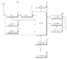
도 2는 도 1의 영상표시장치의 내부 블록도의 일예이다.FIG. 2 is an example of an internal block diagram of the image display device of FIG. 1.
도 2를 참조하면, 본 발명의 일실시예에 의한 영상표시장치(100)는, 방송 수신부(105), 외부장치 인터페이스부(130), 저장부(140), 사용자입력 인터페이스부(150), 센서부(미도시), 제어부(170), 디스플레이(180), 오디오 출력부(185)를 포함할 수 있다.Referring to FIG. 2, the
방송 수신부(105)는, 튜너부(110), 복조부(120), 네트워크 인터페이스부(130), 외부장치 인터페이스부(135)를 포함할 수 있다.The
한편, 방송 수신부(105)는, 도면과 달리, 튜너부(110), 복조부(120)와, 외부장치 인터페이스부(135)만을 포함하는 것도 가능하다. 즉, 네트워크 인터페이스부(130)를 포함하지 않을 수도 있다.Meanwhile, unlike the drawing, the
튜너부(110)는, 안테나(미도시)를 통해 수신되는 RF(Radio Frequency) 방송 신호 중 사용자에 의해 선택된 채널 또는 기저장된 모든 채널에 해당하는 RF 방송 신호를 선택한다. 또한, 선택된 RF 방송 신호를 중간 주파수 신호 혹은 베이스 밴드 영상 또는 음성신호로 변환한다. The
예를 들어, 선택된 RF 방송 신호가 디지털 방송 신호이면 디지털 IF 신호(DIF)로 변환하고, 아날로그 방송 신호이면 아날로그 베이스 밴드 영상 또는 음성 신호(CVBS/SIF)로 변환한다. 즉, 튜너부(110)는 디지털 방송 신호 또는 아날로그 방송 신호를 처리할 수 있다. 튜너부(110)에서 출력되는 아날로그 베이스 밴드 영상 또는 음성 신호(CVBS/SIF)는 제어부(170)로 직접 입력될 수 있다.For example, if the selected RF broadcast signal is a digital broadcast signal, it is converted to a digital IF signal (DIF), and if it is an analog broadcast signal, it is converted to an analog baseband video or audio signal (CVBS / SIF). That is, the
한편, 튜너부(110)는, 복수 채널의 방송 신호를 수신하기 위해, 복수의 튜너를 구비하는 것이 가능하다. 또는, 복수 채널의 방송 신호를 동시에 수신하는 단일 튜너도 가능하다.On the other hand, the
복조부(120)는 튜너부(110)에서 변환된 디지털 IF 신호(DIF)를 수신하여 복조 동작을 수행한다. The
복조부(120)는 복조 및 채널 복호화를 수행한 후 스트림 신호(TS)를 출력할 수 있다. 이때 스트림 신호는 영상 신호, 음성 신호 또는 데이터 신호가 다중화된 신호일 수 있다. The
복조부(120)에서 출력한 스트림 신호는 제어부(170)로 입력될 수 있다. 제어부(170)는 역다중화, 영상/음성 신호 처리 등을 수행한 후, 디스플레이(180)에 영상을 출력하고, 오디오 출력부(185)로 음성을 출력한다. The stream signal output from the
외부장치 인터페이스부(130)는, 접속된 외부 장치(미도시), 예를 들어, 셋탑 박스(50)와 데이터를 송신 또는 수신할 수 있다. 이를 위해, 외부장치 인터페이스부(130)는, A/V 입출력부(미도시)를 포함할 수 있다. The external
외부장치 인터페이스부(130)는, DVD(Digital Versatile Disk), 블루레이(Blu ray), 게임기기, 카메라, 캠코더, 컴퓨터(노트북), 셋탑 박스 등과 같은 외부 장치와 유/무선으로 접속될 수 있으며, 외부 장치와 입력/출력 동작을 수행할 수도 있다. The external
A/V 입출력부는, 외부 장치의 영상 및 음성 신호를 입력받을 수 있다. 한편, 무선 통신부(미도시)는, 다른 전자기기와 근거리 무선 통신을 수행할 수 있다. The A / V input / output unit may receive video and audio signals from an external device. Meanwhile, the wireless communication unit (not shown) may perform short-range wireless communication with other electronic devices.
이러한 무선 통신부(미도시)를 통해, 외부장치 인터페이스부(130)는, 인접하는 이동 단말기(600)와 데이터를 교환할 수 있다. 특히, 외부장치 인터페이스부(130)는, 미러링 모드에서, 이동 단말기(600)로부터 디바이스 정보, 실행되는 애플리케이션 정보, 애플리케이션 이미지 등을 수신할 수 있다. Through such a wireless communication unit (not shown), the external
네트워크 인터페이스부(135)는, 영상표시장치(100)를 인터넷망을 포함하는 유/무선 네트워크와 연결하기 위한 인터페이스를 제공한다. 예를 들어, 네트워크 인터페이스부(135)는, 네트워크를 통해, 인터넷 또는 컨텐츠 제공자 또는 네트워크 운영자가 제공하는 컨텐츠 또는 데이터들을 수신할 수 있다. The
한편, 네트워크 인터페이스부(135)는, 무선 통신부(미도시)를 포함할 수 있다. Meanwhile, the
저장부(140)는, 제어부(170) 내의 각 신호 처리 및 제어를 위한 프로그램이 저장될 수도 있고, 신호 처리된 영상, 음성 또는 데이터 신호를 저장할 수도 있다. The
또한, 저장부(140)는 외부장치 인터페이스부(130)로 입력되는 영상, 음성 또는 데이터 신호의 임시 저장을 위한 기능을 수행할 수도 있다. 또한, 저장부(140)는, 채널 맵 등의 채널 기억 기능을 통하여 소정 방송 채널에 관한 정보를 저장할 수 있다. Also, the
도 2의 저장부(140)가 제어부(170)와 별도로 구비된 실시예를 도시하고 있으나, 본 발명의 범위는 이에 한정되지 않는다. 저장부(140)는 제어부(170) 내에 포함될 수 있다. Although the
사용자입력 인터페이스부(150)는, 사용자가 입력한 신호를 제어부(170)로 전달하거나, 제어부(170)로부터의 신호를 사용자에게 전달한다. The user
예를 들어, 원격제어장치(200)로부터 전원 온/오프, 채널 선택, 화면 설정 등의 사용자 입력 신호를 송신/수신하거나, 전원키, 채널키, 볼륨키, 설정치 등의 로컬키(미도시)에서 입력되는 사용자 입력 신호를 제어부(170)에 전달하거나, 사용자의 제스처를 센싱하는 센서부(미도시)로부터 입력되는 사용자 입력 신호를 제어부(170)에 전달하거나, 제어부(170)로부터의 신호를 센서부(미도시)로 송신할 수 있다. For example, the
제어부(170)는, 튜너부(110) 또는 복조부(120) 또는 네트워크 인터페이스부(135) 또는 외부장치 인터페이스부(130)를 통하여, 입력되는 스트림을 역다중화하거나, 역다중화된 신호들을 처리하여, 영상 또는 음성 출력을 위한 신호를 생성 및 출력할 수 있다. The
제어부(170)에서 영상 처리된 영상 신호는 디스플레이(180)로 입력되어, 해당 영상 신호에 대응하는 영상으로 표시될 수 있다. 또한, 제어부(170)에서 영상 처리된 영상 신호는 외부장치 인터페이스부(130)를 통하여 외부 출력장치로 입력될 수 있다. The image signal processed by the
제어부(170)에서 처리된 음성 신호는 오디오 출력부(185)로 음향 출력될 수 있다. 또한, 제어부(170)에서 처리된 음성 신호는 외부장치 인터페이스부(130)를 통하여 외부 출력장치로 입력될 수 있다. The audio signal processed by the
도 2에는 도시되어 있지 않으나, 제어부(170)는 역다중화부, 영상처리부 등을 포함할 수 있다. 이에 대해서는 도 3을 참조하여 후술한다.Although not illustrated in FIG. 2, the
그 외, 제어부(170)는, 영상표시장치(100) 내의 전반적인 동작을 제어할 수 있다. 예를 들어, 제어부(170)는 튜너부(110)를 제어하여, 사용자가 선택한 채널 또는 기저장된 채널에 해당하는 RF 방송을 선택(Tuning)하도록 제어할 수 있다. In addition, the
또한, 제어부(170)는 사용자입력 인터페이스부(150)를 통하여 입력된 사용자 명령 또는 내부 프로그램에 의하여 영상표시장치(100)를 제어할 수 있다. In addition, the
한편, 제어부(170)는, 영상을 표시하도록 디스플레이(180)를 제어할 수 있다. 이때, 디스플레이(180)에 표시되는 영상은, 정지 영상 또는 동영상일 수 있으며, 2D 영상 또는 3D 영상일 수 있다.Meanwhile, the
한편, 제어부(170)는 디스플레이(180)에 표시되는 영상 내에, 소정 오브젝트가 표시되도록 할 수 있다. 예를 들어, 오브젝트는, 접속된 웹 화면(신문, 잡지 등), EPG(Electronic Program Guide), 다양한 메뉴, 위젯, 아이콘, 정지 영상, 동영상, 텍스트 중 적어도 하나일 수 있다. Meanwhile, the
한편, 제어부(170)는, 촬영부(미도시)로부터 촬영된 영상에 기초하여, 사용자의 위치를 인식할 수 있다. 예를 들어, 사용자와 영상표시장치(100) 간의 거리(z축 좌표)를 파악할 수 있다. 그 외, 사용자 위치에 대응하는 디스플레이(180) 내의 x축 좌표, 및 y축 좌표를 파악할 수 있다.Meanwhile, the
디스플레이(180)는, 제어부(170)에서 처리된 영상 신호, 데이터 신호, OSD 신호, 제어 신호 또는 외부장치 인터페이스부(130)에서 수신되는 영상 신호, 데이터 신호, 제어 신호 등을 변환하여 구동 신호를 생성한다. The
한편, 디스플레이(180)는, 터치 스크린으로 구성되어 출력 장치 이외에 입력 장치로 사용되는 것도 가능하다.Meanwhile, the
오디오 출력부(185)는, 제어부(170)에서 음성 처리된 신호를 입력 받아 음성으로 출력한다. The
촬영부(미도시)는 사용자를 촬영한다. 촬영부(미도시)는 1 개의 카메라로 구현되는 것이 가능하나, 이에 한정되지 않으며, 복수 개의 카메라로 구현되는 것도 가능하다. 촬영부(미도시)에서 촬영된 영상 정보는 제어부(170)에 입력될 수 있다. The photographing unit (not shown) photographs the user. The photographing unit (not shown) may be implemented with one camera, but is not limited thereto, and may be implemented with a plurality of cameras. Image information photographed by the photographing unit (not shown) may be input to the
제어부(170)는, 촬영부(미도시)로부터 촬영된 영상, 또는 센서부(미도시)로부터의 감지된 신호 각각 또는 그 조합에 기초하여 사용자의 제스처를 감지할 수 있다. The
전원 공급부(190)는, 영상표시장치(100) 전반에 걸쳐 해당 전원을 공급한다. 특히, 시스템 온 칩(System On Chip,SOC)의 형태로 구현될 수 있는 제어부(170)와, 영상 표시를 위한 디스플레이(180), 및 오디오 출력을 위한 오디오 출력부(185) 등에 전원을 공급할 수 있다. The
구체적으로, 전원 공급부(190)는, 교류 전원을 직류 전원으로 변환하는 컨버터와, 직류 전원의 레벨을 변환하는 dc/dc 컨버터를 구비할 수 있다.Specifically, the
원격제어장치(200)는, 사용자 입력을 사용자입력 인터페이스부(150)로 송신한다. 이를 위해, 원격제어장치(200)는, 블루투스(Bluetooth), RF(Radio Frequency) 통신, 적외선(IR) 통신, UWB(Ultra Wideband), 지그비(ZigBee) 방식 등을 사용할 수 있다. 또한, 원격제어장치(200)는, 사용자입력 인터페이스부(150)에서 출력한 영상, 음성 또는 데이터 신호 등을 수신하여, 이를 원격제어장치(200)에서 표시하거나 음성 출력할 수 있다.The
한편, 상술한 영상표시장치(100)는, 고정형 또는 이동형 디지털 방송 수신 가능한 디지털 방송 수신기일 수 있다. Meanwhile, the above-described
한편, 도 2에 도시된 영상표시장치(100)의 블록도는 본 발명의 일실시예를 위한 블록도이다. 블록도의 각 구성요소는 실제 구현되는 영상표시장치(100)의 사양에 따라 통합, 추가, 또는 생략될 수 있다. 즉, 필요에 따라 2 이상의 구성요소가 하나의 구성요소로 합쳐지거나, 혹은 하나의 구성요소가 2 이상의 구성요소로 세분되어 구성될 수 있다. 또한, 각 블록에서 수행하는 기능은 본 발명의 실시예를 설명하기 위한 것이며, 그 구체적인 동작이나 장치는 본 발명의 권리범위를 제한하지 아니한다.Meanwhile, the block diagram of the
도 3은 도 2의 제어부의 내부 블록도의 일예이다. 3 is an example of an internal block diagram of the control unit of FIG. 2.
도면을 참조하여 설명하면, 본 발명의 일실시예에 의한 제어부(170)는, 역다중화부(310), 영상 처리부(320), 프로세서(330), OSD 생성부(340), 믹서(345), 프레임 레이트 변환부(350), 및 포맷터(360)를 포함할 수 있다. 그 외 오디오 처리부(미도시), 데이터 처리부(미도시)를 더 포함할 수 있다.Referring to the drawings, the
역다중화부(310)는, 입력되는 스트림을 역다중화한다. 예를 들어, MPEG-2 TS가 입력되는 경우 이를 역다중화하여, 각각 영상, 음성 및 데이터 신호로 분리할 수 있다. 여기서, 역다중화부(310)에 입력되는 스트림 신호는, 튜너부(110) 또는 복조부(120) 또는 외부장치 인터페이스부(130)에서 출력되는 스트림 신호일 수 있다.The
영상 처리부(320)는, 역다중화된 영상 신호의 영상 처리를 수행할 수 있다. 이를 위해, 영상 처리부(320)는, 영상 디코더(325), 및 스케일러(335)를 구비할 수 있다. The
영상 디코더(325)는, 역다중화된 영상신호를 복호화하며, 스케일러(335)는, 복호화된 영상신호의 해상도를 디스플레이(180)에서 출력 가능하도록 스케일링(scaling)을 수행한다.The
영상 디코더(325)는 다양한 규격의 디코더를 구비하는 것이 가능하다. 예를 들어, MPEG-2, H,264 디코더, 색차 영상(color image) 및 깊이 영상(depth image)에 대한 3D 영상 디코더, 복수 시점 영상에 대한 디코더 등을 구비할 수 있다. The
프로세서(330)는, 영상표시장치(100) 내 또는 제어부(170) 내의 전반적인 동작을 제어할 수 있다. 예를 들어, 프로세서(330)는 튜너(110)를 제어하여, 사용자가 선택한 채널 또는 기저장된 채널에 해당하는 RF 방송을 선택(Tuning)하도록 제어할 수 있다. The
또한, 프로세서(330)는, 사용자입력 인터페이스부(150)를 통하여 입력된 사용자 명령 또는 내부 프로그램에 의하여 영상표시장치(100)를 제어할 수 있다. In addition, the
또한, 프로세서(330)는, 네트워크 인터페이스부(135) 또는 외부장치 인터페이스부(130)와의 데이터 전송 제어를 수행할 수 있다. In addition, the
또한, 프로세서(330)는, 제어부(170) 내의 역다중화부(310), 영상 처리부(320), OSD 생성부(340) 등의 동작을 제어할 수 있다. In addition, the
OSD 생성부(340)는, 사용자 입력에 따라 또는 자체적으로 OSD 신호를 생성한다. 예를 들어, 사용자 입력 신호에 기초하여, 디스플레이(180)의 화면에 각종 정보를 그래픽(Graphic)이나 텍스트(Text)로 표시하기 위한 신호를 생성할 수 있다. 생성되는 OSD 신호는, 영상표시장치(100)의 사용자 인터페이스 화면, 다양한 메뉴 화면, 위젯, 아이콘 등의 다양한 데이터를 포함할 수 있다. 또한, 생성되는 OSD 신호는, 2D 오브젝트 또는 3D 오브젝트를 포함할 수 있다. The
또한, OSD 생성부(340)는, 원격제어장치(200)로부터 입력되는 포인팅 신호에 기초하여, 디스플레이에 표시 가능한, 포인터를 생성할 수 있다. 특히, 이러한 포인터는, 포인팅 신호 처리부에서 생성될 수 있으며, OSD 생성부(240)는, 이러한 포인팅 신호 처리부(미도시)를 포함할 수 있다. 물론, 포인팅 신호 처리부(미도시)가 OSD 생성부(240) 내에 구비되지 않고 별도로 마련되는 것도 가능하다.In addition, the
믹서(345)는, OSD 생성부(340)에서 생성된 OSD 신호와 영상 처리부(320)에서 영상 처리된 복호화된 영상 신호를 믹싱할 수 있다. 믹싱된 영상 신호는 프레임 레이트 변환부(350)에 제공된다.The
프레임 레이트 변환부(Frame Rate Conveter, FRC)(350)는, 입력되는 영상의 프레임 레이트를 변환할 수 있다. 한편, 프레임 레이트 변환부(350)는, 별도의 프레임 레이트 변환 없이, 그대로 출력하는 것도 가능하다. The frame rate converter (FRC) 350 may convert the frame rate of the input image. On the other hand, the frame
한편, 포맷터(Formatter)(360)는, 입력되는 영상 신호의 포맷을, 디스플레이에 표시하기 위한 영상 신호로 변화시켜 출력할 수 있다.On the other hand, the formatter (Formatter) 360, the format of the input video signal can be output by changing to a video signal for display on the display.
포맷터(360)는, 영상 신호의 포맷을 변경할 수 있다. 예를 들어, 3D 영상 신호의 포맷을, 사이드 바이 사이드(Side by Side) 포맷, 탑 다운(Top / Down) 포맷, 프레임 시퀀셜(Frame Sequential) 포맷, 인터레이스 (Interlaced) 포맷, 체커 박스(Checker Box) 포맷 등의 다양한 3D 포맷 중 어느 하나의 포맷으로 변경할 수 있다. The
한편, 제어부(170) 내의 오디오 처리부(미도시)는, 역다중화된 음성 신호의 음성 처리를 수행할 수 있다. 이를 위해 오디오 처리부(미도시)는 다양한 디코더를 구비할 수 있다.Meanwhile, the audio processing unit (not shown) in the
또한, 제어부(170) 내의 오디오 처리부(미도시)는, 베이스(Base), 트레블(Treble), 음량 조절 등을 처리할 수 있다. In addition, the audio processing unit (not shown) in the
제어부(170) 내의 데이터 처리부(미도시)는, 역다중화된 데이터 신호의 데이터 처리를 수행할 수 있다. 예를 들어, 역다중화된 데이터 신호가 부호화된 데이터 신호인 경우, 이를 복호화할 수 있다. 부호화된 데이터 신호는, 각 채널에서 방영되는 방송프로그램의 시작시간, 종료시간 등의 방송정보를 포함하는 전자 프로그램 가이드 정보(Electronic Program Guide) 정보일 수 있다. The data processing unit (not shown) in the
한편, 도 3에 도시된 제어부(170)의 블록도는 본 발명의 일실시예를 위한 블록도이다. 블록도의 각 구성요소는 실제 구현되는 제어부(170)의 사양에 따라 통합, 추가, 또는 생략될 수 있다. On the other hand, the block diagram of the
특히, 프레임 레이트 변환부(350), 및 포맷터(360)는 제어부(170) 내에 마련되지 않고, 각각 별도로 구비되거나, 하나의 모듈로서 별도로 구비될 수도 있다.In particular, the
도 4a는 도 2의 원격제어장치의 제어 방법을 도시한 도면이다.4A is a diagram illustrating a control method of the remote control device of FIG. 2.
도 4a의 (a)에 도시된 바와 같이, 디스플레이(180)에 원격제어장치(200)에 대응하는 포인터(205)가 표시되는 것을 예시한다. As illustrated in (a) of FIG. 4A, it is illustrated that a
사용자는 원격제어장치(200)를 상하, 좌우(도 4a의 (b)), 앞뒤(도 4a의 (c))로 움직이거나 회전할 수 있다. 영상표시장치의 디스플레이(180)에 표시된 포인터(205)는 원격제어장치(200)의 움직임에 대응한다. 이러한 원격제어장치(200)는, 도면과 같이, 3D 공간 상의 움직임에 따라 해당 포인터(205)가 이동되어 표시되므로, 공간 리모콘 또는 3D 포인팅 장치라 명명할 수 있다. The user can move or rotate the
도 4a의 (b)는 사용자가 원격제어장치(200)를 왼쪽으로 이동하면, 영상표시장치의 디스플레이(180)에 표시된 포인터(205)도 이에 대응하여 왼쪽으로 이동하는 것을 예시한다. 4A (b) illustrates that when the user moves the
원격제어장치(200)의 센서를 통하여 감지된 원격제어장치(200)의 움직임에 관한 정보는 영상표시장치로 전송된다. 영상표시장치는 원격제어장치(200)의 움직임에 관한 정보로부터 포인터(205)의 좌표를 산출할 수 있다. 영상표시장치는 산출한 좌표에 대응하도록 포인터(205)를 표시할 수 있다.Information on the movement of the
도 4a의 (c)는, 원격제어장치(200) 내의 특정 버튼을 누른 상태에서, 사용자가 원격제어장치(200)를 디스플레이(180)에서 멀어지도록 이동하는 경우를 예시한다. 이에 의해, 포인터(205)에 대응하는 디스플레이(180) 내의 선택 영역이 줌인되어 확대 표시될 수 있다. 이와 반대로, 사용자가 원격제어장치(200)를 디스플레이(180)에 가까워지도록 이동하는 경우, 포인터(205)에 대응하는 디스플레이(180) 내의 선택 영역이 줌아웃되어 축소 표시될 수 있다. 한편, 원격제어장치(200)가 디스플레이(180)에서 멀어지는 경우, 선택 영역이 줌아웃되고, 원격제어장치(200)가 디스플레이(180)에 가까워지는 경우, 선택 영역이 줌인될 수도 있다.FIG. 4A (c) illustrates a case in which a user moves the
한편, 원격제어장치(200) 내의 특정 버튼을 누른 상태에서는 상하, 좌우 이동의 인식이 배제될 수 있다. 즉, 원격제어장치(200)가 디스플레이(180)에서 멀어지거나 접근하도록 이동하는 경우, 상,하,좌,우 이동은 인식되지 않고, 앞뒤 이동만 인식되도록 할 수 있다. 원격제어장치(200) 내의 특정 버튼을 누르지 않은 상태에서는, 원격제어장치(200)의 상,하, 좌,우 이동에 따라 포인터(205)만 이동하게 된다. Meanwhile, in a state in which a specific button in the
한편, 포인터(205)의 이동속도나 이동방향은 원격제어장치(200)의 이동속도나 이동방향에 대응할 수 있다. Meanwhile, the moving speed or the moving direction of the
도 4b는 도 2의 원격제어장치의 내부 블록도이다.4B is an internal block diagram of the remote control device of FIG. 2.
도면을 참조하여 설명하면, 원격제어장치(200)는 무선통신부(425), 사용자 입력부(435), 센서부(440), 출력부(450), 전원공급부(460), 저장부(470), 제어부(480)를 포함할 수 있다. Referring to the drawings, the
무선통신부(425)는 전술하여 설명한 본 발명의 실시예들에 따른 영상표시장치 중 임의의 어느 하나와 신호를 송수신한다. 본 발명의 실시예들에 따른 영상표시장치들 중에서, 하나의 영상표시장치(100)를 일예로 설명하도록 하겠다.The wireless communication unit 425 transmits and receives a signal to any one of the video display device according to the embodiments of the present invention described above. Among video display devices according to embodiments of the present invention, one
본 실시예에서, 원격제어장치(200)는 RF 통신규격에 따라 영상표시장치(100)와 신호를 송수신할 수 있는 RF 모듈(421)을 구비할 수 있다. 또한 원격제어장치(200)는 IR 통신규격에 따라 영상표시장치(100)와 신호를 송수신할 수 있는 IR 모듈(423)을 구비할 수 있다. In this embodiment, the
본 실시예에서, 원격제어장치(200)는 영상표시장치(100)로 원격제어장치(200)의 움직임 등에 관한 정보가 담긴 신호를 RF 모듈(421)을 통하여 전송한다. In this embodiment, the
또한, 원격제어장치(200)는 영상표시장치(100)가 전송한 신호를 RF 모듈(421)을 통하여 수신할 수 있다. 또한, 원격제어장치(200)는 필요에 따라 IR 모듈(423)을 통하여 영상표시장치(100)로 전원 온/오프, 채널 변경, 볼륨 변경 등에 관한 명령을 전송할 수 있다. Also, the
사용자 입력부(435)는 키패드, 버튼, 터치 패드, 또는 터치 스크린 등으로 구성될 수 있다. 사용자는 사용자 입력부(435)를 조작하여 원격제어장치(200)로 영상표시장치(100)와 관련된 명령을 입력할 수 있다. 사용자 입력부(435)가 하드키 버튼을 구비할 경우 사용자는 하드키 버튼의 푸쉬 동작을 통하여 원격제어장치(200)로 영상표시장치(100)와 관련된 명령을 입력할 수 있다. 사용자 입력부(435)가 터치스크린을 구비할 경우 사용자는 터치스크린의 소프트키를 터치하여 원격제어장치(200)로 영상표시장치(100)와 관련된 명령을 입력할 수 있다. 또한, 사용자 입력부(435)는 스크롤 키나, 조그 키 등 사용자가 조작할 수 있는 다양한 종류의 입력수단을 구비할 수 있으며 본 실시예는 본 발명의 권리범위를 제한하지 아니한다.The user input unit 435 may include a keypad, a button, a touch pad, or a touch screen. The user may input a command related to the
센서부(440)는 자이로 센서(441) 또는 가속도 센서(443)를 구비할 수 있다. 자이로 센서(441)는 원격제어장치(200)의 움직임에 관한 정보를 센싱할 수 있다. The
일예로, 자이로 센서(441)는 원격제어장치(200)의 동작에 관한 정보를 x,y,z 축을 기준으로 센싱할 수 있다. 가속도 센서(443)는 원격제어장치(200)의 이동속도 등에 관한 정보를 센싱할 수 있다. 한편, 거리측정센서를 더 구비할 수 있으며, 이에 의해, 디스플레이(180)와의 거리를 센싱할 수 있다.For example, the
출력부(450)는 사용자 입력부(435)의 조작에 대응하거나 영상표시장치(100)에서 전송한 신호에 대응하는 영상 또는 음성 신호를 출력할 수 있다. 출력부(450)를 통하여 사용자는 사용자 입력부(435)의 조작 여부 또는 영상표시장치(100)의 제어 여부를 인지할 수 있다. The
일예로, 출력부(450)는 사용자 입력부(435)가 조작되거나 무선 통신부(425)을 통하여 영상표시장치(100)와 신호가 송수신되면 점등되는 LED 모듈(451), 진동을 발생하는 진동 모듈(453), 음향을 출력하는 음향 출력 모듈(455), 또는 영상을 출력하는 디스플레이 모듈(457)을 구비할 수 있다. For example, the
전원공급부(460)는 원격제어장치(200)로 전원을 공급한다. 전원공급부(460)는 원격제어장치(200)이 소정 시간 동안 움직이지 않은 경우 전원 공급을 중단함으로서 전원 낭비를 줄일 수 있다. 전원공급부(460)는 원격제어장치(200)에 구비된 소정 키가 조작된 경우에 전원 공급을 재개할 수 있다.The
저장부(470)는 원격제어장치(200)의 제어 또는 동작에 필요한 여러 종류의 프로그램, 애플리케이션 데이터 등이 저장될 수 있다. 만일 원격제어장치(200)가 영상표시장치(100)와 RF 모듈(421)을 통하여 무선으로 신호를 송수신할 경우 원격제어장치(200)와 영상표시장치(100)는 소정 주파수 대역을 통하여 신호를 송수신한다. 원격제어장치(200)의 제어부(480)는 원격제어장치(200)와 페어링된 영상표시장치(100)와 신호를 무선으로 송수신할 수 있는 주파수 대역 등에 관한 정보를 저장부(470)에 저장하고 참조할 수 있다.The
제어부(480)는 원격제어장치(200)의 제어에 관련된 제반사항을 제어한다. 제어부(480)는 사용자 입력부(435)의 소정 키 조작에 대응하는 신호 또는 센서부(440)에서 센싱한 원격제어장치(200)의 움직임에 대응하는 신호를 무선 통신부(425)를 통하여 영상표시장치(100)로 전송할 수 있다.The
영상표시장치(100)의 사용자 입력 인터페이스부(150)는, 원격제어장치(200)와 무선으로 신호를 송수신할 수 있는 무선통신부(151)와, 원격제어장치(200)의 동작에 대응하는 포인터의 좌표값을 산출할 수 있는 좌표값 산출부(415)를 구비할 수 있다. The user
사용자 입력 인터페이스부(150)는, RF 모듈(412)을 통하여 원격제어장치(200)와 무선으로 신호를 송수신할 수 있다. 또한 IR 모듈(413)을 통하여 원격제어장치(200)이 IR 통신 규격에 따라 전송한 신호를 수신할 수 있다.The user
좌표값 산출부(415)는 무선통신부(151)를 통하여 수신된 원격제어장치(200)의 동작에 대응하는 신호로부터 손떨림이나 오차를 수정하여 디스플레이(170)에 표시할 포인터(205)의 좌표값(x,y)을 산출할 수 있다.The coordinate
사용자 입력 인터페이스부(150)를 통하여 영상표시장치(100)로 입력된 원격제어장치(200) 전송 신호는 영상표시장치(100)의 제어부(180)로 전송된다. 제어부(180)는 원격제어장치(200)에서 전송한 신호로부터 원격제어장치(200)의 동작 및 키 조작에 관한 정보를 판별하고, 그에 대응하여 영상표시장치(100)를 제어할 수 있다.The transmission signal of the
또 다른 예로, 원격제어장치(200)는, 그 동작에 대응하는 포인터 좌표값을 산출하여 영상표시장치(100)의 사용자 입력 인터페이스부(150)로 출력할 수 있다. 이 경우, 영상표시장치(100)의 사용자 입력 인터페이스부(150)는 별도의 손떨림이나 오차 보정 과정 없이 수신된 포인터 좌표값에 관한 정보를 제어부(180)로 전송할 수 있다.As another example, the
또한, 다른 예로, 좌표값 산출부(415)가, 도면과 달리 사용자 입력 인터페이스부(150)가 아닌, 제어부(170) 내부에 구비되는 것도 가능하다.In addition, as another example, the coordinate
도 5는 도 2의 디스플레이의 내부 블록도이다.5 is an internal block diagram of the display of FIG. 2.
도면을 참조하면, 유기발광패널 기반의 디스플레이(180)는, 유기발광패널(210), 제1 인터페이스부(230), 제2 인터페이스부(231), 타이밍 컨트롤러(232), 게이트 구동부(234), 데이터 구동부(236), 메모리(240), 프로세서(270), 전원 공급부(290), 전류 검출부(1110) 등을 포함할 수 있다.Referring to the drawings, the organic light emitting panel-based
디스플레이(180)는, 영상 신호(Vd)와, 제1 직류 전원(V1) 및 제2 직류 전원(V2)을 수신하고, 영상 신호(Vd)에 기초하여, 소정 영상을 표시할 수 있다.The
한편, 디스플레이(180) 내의 제1 인터페이스부(230)는, 제어부(170)로부터 영상 신호(Vd)와, 제1 직류 전원(V1)을 수신할 수 있다.Meanwhile, the
여기서, 제1 직류 전원(V1)은, 디스플레이(180) 내의 전원 공급부(290), 및 타이밍 컨트롤러(232)의 동작을 위해 사용될 수 있다. Here, the first DC power supply V1 may be used for the operation of the
다음, 제2 인터페이스부(231)는, 외부의 전원 공급부(190)로부터 제2 직류 전원(V2)을 수신할 수 있다. 한편, 제2 직류 전원(V2)은, 디스플레이(180) 내의 데이터 구동부(236)에 입력될 수 있다. Next, the
타이밍 컨트롤러(232)는, 영상 신호(Vd)에 기초하여, 데이터 구동 신호(Sda) 및 게이트 구동 신호(Sga)를 출력할 수 있다.The
예를 들어, 제1 인터페이스부(230)가 입력되는 영상 신호(Vd)를 변환하여 변환된 영상 신호(va1)를 출력하는 경우, 타이밍 컨트롤러(232)는, 변환된 영상 신호(va1)에 기초하여, 데이터 구동 신호(Sda) 및 게이트 구동 신호(Sga)를 출력할 수 있다.For example, when the
타이밍 컨트롤러(timing controller)(232)는, 제어부(170)로부터의 비디오 신호(Vd) 외에, 제어 신호, 수직동기신호(Vsync) 등을 더 수신할 수 있다.The
그리고, 타이밍 컨트롤러(timing controller)(232)는, 비디오 신호(Vd) 외에, 제어 신호, 수직동기신호(Vsync) 등에 기초하여, 게이트 구동부(234)의 동작을 위한 게이트 구동 신호(Sga), 데이터 구동부(236)의 동작을 위한 데이터 구동 신호(Sda)를 출력할 수 있다.In addition, the
한편, 타이밍 컨트롤러(232)는, 게이트 구동부(234)에 제어 신호(Cs)를 더 출력할 수 있다.Meanwhile, the
게이트 구동부(234)와 데이터 구동부(236)는, 타이밍 컨트롤러(232)로부터의 게이트 구동 신호(Sga), 데이터 구동 신호(Sda)에 따라, 각각 게이트 라인(GL) 및 데이터 라인(DL)을 통해, 주사 신호 및 영상 신호를 유기발광패널(210)에 공급한다. 이에 따라, 유기발광패널(210)은 소정 영상을 표시하게 된다.The
한편, 유기발광패널(210)은, 유기 발광층을 포함할 수 있으며, 영상을 표시하기 위해, 유기 발광층에 대응하는 각 화소에, 다수개의 게이트 라인(GL) 및 데이터 라인(DL)이 매트릭스 형태로 교차하여 배치될 수 있다. Meanwhile, the organic
한편, 데이터 구동부(236)는, 제2 인터페이스부(231)로부터의 제2 직류 전원(V2)에 기초하여, 유기발광패널(210)에 데이터 신호를 출력할 수 있다.Meanwhile, the
전원 공급부(290)는, 각종 전원을, 게이트 구동부(234)와 데이터 구동부(236), 타이밍 컨트롤러(232) 등에 공급할 수 있다.The
전류 검출부(1110)는, 유기발광패널(210)의 서브픽셀에 흐르는 전류를 검출할 수 있다. 검출되는 전류는, 누적 전류 연산을 위해, 프로세서(270) 등에 입력될 수 있다.The
프로세서(270)는, 디스플레이(180) 내의 각 종 제어를 수행할 수 있다. 예를 들어, 게이트 구동부(234)와 데이터 구동부(236), 타이밍 컨트롤러(232) 등을 제어할 수 있다.The
한편, 프로세서(270)는, 전류 검출부(1110)로부터, 유기발광패널(210)의 서브픽셀에 흐르는 전류 정보를 수신할 수 있다.Meanwhile, the
그리고, 프로세서(270)는, 유기발광패널(210)의 서브픽셀에 흐르는 전류 정보에 기초하여, 각 유기발광패널(210)의 서브픽셀의 누적 전류를 연산할 수 있다. 연산되는 누적 전류는, 메모리(240)에 저장될 수 있다.In addition, the
한편, 프로세서(270)는, 각 유기발광패널(210)의 서브픽셀의 누적 전류가, 허용치 이상인 경우, 번인(burn in)으로 판단할 수 있다.On the other hand, the
예를 들어, 프로세서(270)는, 각 유기발광패널(210)의 서브픽셀의 누적 전류가, 300000 A 이상인 경우, 번인된 서브픽셀로 판단할 수 있다.For example, when the accumulated current of the sub-pixels of each organic light-emitting
한편, 프로세서(270)는, 각 유기발광패널(210)의 서브픽셀 중 일부 서브픽셀의 누적 전류가, 허용치에 근접하는 경우, 해당 서브픽셀을, 번인이 예측되는 서브픽셀로 판단할 수 있다.Meanwhile, when the accumulated current of some subpixels among the subpixels of each organic
한편, 프로세서(270)는, 전류 검출부(1110)에서 검출된 전류에 기초하여, 가장 누적 전류가 큰 서브픽셀을, 번인 예측 서브픽셀로 판단할 수 있다.Meanwhile, the
한편, 프로세서(270)는, 전류 검출부(1110)에서 검출된 전류에 기초하여, 유기발광패널(210) 내의 번인 서브픽셀 또는 번인 예측 서브픽셀을 연산하고, 연산된 번인 서브픽셀 또는 번인 예측 서브픽셀 주변의 서브픽셀에, 할당된 전류 보다 낮은 전류가 흐르도록 제어할 수 있다. 이에 따라, 번인 서브픽셀 주변의 서브픽셀의 번인(burn in)이 연장되도록 할 수 있다. 결국, 유기발광패널(210)을 구비하는 영상표시장치(100)의 전체 수명을 연장시킬 수 있게 된다.Meanwhile, the
한편, 프로세서(270)는, 연산된 번인 서브픽셀에, 할당된 전류 보다 높은 전류가 흐르도록 제어할 수 있으며, 이에 따라, 연산된 번인 서브픽셀 주변에 낮은 전류가 흘러, 휘도가 낮아지는 현상을 방지할 수 있게 된다.Meanwhile, the
한편, 프로세서(270)는, 유기발광패널(210) 내에, 번인이 발생하지 않은 경우, 번인 예측되는, 번인 예측 서브픽셀 주변의 서브픽셀에, 할당된 전류 보다 낮은 전류가 흐르도록 제어함으로써, 번인 예측 서브픽셀 주변의 서브픽셀의 번인(burn in)이 연장되도록 할 수 있다. 결국, 유기발광패널(210)을 구비하는 영상표시장치(100)의 전체 수명을 연장시킬 수 있게 된다.On the other hand, the
한편, 프로세서(270)는, 연산된 번인 서브픽셀 또는 번인 예측 서브픽셀 주변의 서브픽셀에, 할당된 데이터 전압 보다 낮은 데이터 전압이 인가되도록 제어할 수 있다.Meanwhile, the
한편, 프로세서(270)는, 유기발광패널(210) 내에, 번인이 발생하지 않은 경우, 번인 예측되는, 번인 예측 서브픽셀에도, 할당된 전류 보다 낮은 전류가 흐르도록 제어함으로써, 번인 예측 서브픽셀의 번인(burn in)이 연장되도록 할 수 있다. 결국, 유기발광패널(210)을 구비하는 영상표시장치(100)의 전체 수명을 연장시킬 수 있게 된다.Meanwhile, the
한편, 프로세서(270)는, 연산된 번인 서브픽셀 또는 번인 예측 서브픽셀 주변의 서브픽셀 중 제1 서브픽셀 보다 더 먼 제2 서브픽셀에, 제1 레벨 보다 높은 제2 레벨의 전류가 흐르도록 제어할 수 있으며, 이에 의하면, 수명이 더 길계 예측되는 제2 서브 픽셀에, 더 높은 전류가 흐르도록 함으로써, 휘도가 낮아지는 현상을 방지할 수 있게 된다.Meanwhile, the
한편, 프로세서(270)는, 전류 검출부(1110)에서 검출된 전류에 기초하여, 유기발광패널(210) 중 누적 전류량이 가장 큰 서브픽셀을 연산하고, 누적 전류량이 가장 큰 서브픽셀 주변의 서브픽셀에, 할당된 전류 보다 낮은 전류가 흐르도록 제어할 수 있다. 이에 의하면, 유기발광패널(210)을 구비하는 영상표시장치(100)의 전체 수명을 연장시킬 수 있게 된다.On the other hand, the
한편, 프로세서(270)는, 누적 전류량이 가장 큰 서브픽셀에, 가까울수록, 누적 전류량이 가장 큰 서브픽셀 주변의 서브픽셀에, 더 낮은 레벨의 전류가 흐르도록 제어함으로써, 유기발광패널(210)을 구비하는 영상표시장치(100)의 전체 수명을 연장시킬 수 있게 된다.Meanwhile, the
도 6a 내지 도 6b는 도 5의 유기발광패널의 설명에 참조되는 도면이다.6A to 6B are views referred to for explanation of the organic light emitting panel of FIG. 5.
먼저, 도 6a는, 유기발광패널(210) 내의 픽셀을 도시하는 도면이다.First, FIG. 6A is a diagram showing pixels in the organic
도면을 참조하면, 유기발광패널(210)은, 복수의 스캔 라인(Scan 1 ~ Scan n)과, 이에 교차하는 복수의 데이터 라인(R1,G1,B1,W1 ~ Rm,Gm,Bm,Wm)을 구비할 수 있다.Referring to the drawings, the organic
한편, 유기발광패널(210) 내의 스캔 라인과, 데이터 라인의 교차 영역에, 픽셀(subpixel)이 정의된다. 도면에서는, RGBW의 서브픽셀(SR1,SG1,SB1,SW1)을 구비하는 픽셀(Pixel)을 도시한다.Meanwhile, a subpixel is defined at an intersection region between the scan line and the data line in the organic
도 6b은, 도 6a의 유기발광패널의 픽셀(Pixel) 내의 어느 하나의 서브픽셀(sub pixel)의 회로를 예시한다. 6B illustrates a circuit of any one sub pixel in a pixel of the organic light emitting panel of FIG. 6A.
도면을 참조하면, 유기발광 서브픽셀(sub pixell) 회로(CRT)는, 능동형으로서, 스위칭 트랜지스터(SW1), 저장 커패시터(Cst), 구동 트랜지스터(SW2), 유기발광층(OLED)을 구비할 수 있다.Referring to the drawings, the organic light emitting sub-pixel (sub pixell) circuit (CRT), as an active type, may include a switching transistor (SW1), a storage capacitor (Cst), a driving transistor (SW2), an organic light emitting layer (OLED) .
스위칭 트랜지스터(SW1)는, 게이트 단자에 스캔 라인(Scan line)이 접속되어, 입력되는 스캔 신호(Vdscan)에 따라 턴 온하게 된다. 턴 온되는 경우, 입력되는 데이터 신호(Vdata)를 구동 트랜지스터(SW2)의 게이트 단자 또는 저장 커패시터(Cst)의 일단으로 전달하게 된다.The switching transistor SW1 is connected to a gate terminal with a scan line and turned on according to the input scan signal Vdscan. When turned on, the input data signal Vdata is transferred to the gate terminal of the driving transistor SW2 or one end of the storage capacitor Cst.
저장 커패시터(Cst)는, 구동 트랜지스터(SW2)의 게이트 단자와 소스 단자 사이에 형성되며, 저장 커패시터(Cst)의 일단에 전달되는 데이터 신호 레벨과, 저장 커패시터(Cst)의 타단에 전달되는 직류 전원(VDD) 레벨의 소정 차이를 저장한다. The storage capacitor Cst is formed between the gate terminal and the source terminal of the driving transistor SW2, and the data signal level transmitted to one end of the storage capacitor Cst and the DC power transferred to the other end of the storage capacitor Cst. (VDD) Stores a predetermined difference in level.
예를 들어, 데이터 신호가, PAM(Pluse Amplitude Modulation) 방식에 따라 서로 다른 레벨을 갖는 경우, 데이터 신호(Vdata)의 레벨 차이에 따라, 저장 커패시터(Cst)에 저장되는 전원 레벨이 달라지게 된다. For example, when the data signals have different levels according to the PAM (Pluse Amplitude Modulation) method, the power level stored in the storage capacitor Cst varies according to the level difference of the data signal Vdata.
다른 예로, 데이터 신호가 PWM(Pluse Width Modulation) 방식에 따라 서로 다른 펄스폭을 갖는 경우, 데이터 신호(Vdata)의 펄스폭 차이에 따라, 저장 커패시터(Cst)에 저장되는 전원 레벨이 달라지게 된다. As another example, when the data signals have different pulse widths according to the PWM (Pluse Width Modulation) method, the power level stored in the storage capacitor Cst varies according to a difference in pulse width of the data signal Vdata.
구동 트랜지스터(SW2)는, 저장 커패시터(Cst)에 저장된 전원 레벨에 따라 턴 온된다. 구동 트랜지스터(SW2)가 턴 온하는 경우, 저장된 전원 레벨에 비례하는, 구동 전류(IOLED)가 유기발광층(OLED)에 흐르게 된다. 이에 따라, 유기발광층(OLED)은 발광동작을 수행하게 된다.The driving transistor SW2 is turned on according to the power level stored in the storage capacitor Cst. When the driving transistor SW2 is turned on, the driving current IOLED, which is proportional to the stored power level, flows in the organic light emitting layer OLED. Accordingly, the organic light emitting layer OLED performs a light emission operation.
유기발광층(OLED)은, 서브픽셀에 대응하는 RGBW의 발광층(EML)을 포함하며, 정공주입층(HIL), 정공 수송층(HTL), 전자 수송층(ETL), 전자 주입층(EIL) 중 적어도 하나를 포함할 수 있으며, 그 외에 정공 저지층 등도 포함할 수 있다.The organic light emitting layer (OLED) includes a light emitting layer (EML) of RGBW corresponding to a subpixel, and at least one of a hole injection layer (HIL), a hole transport layer (HTL), an electron transport layer (ETL), and an electron injection layer (EIL) It may include, in addition, may also include a hole blocking layer.
한편, 서브픽셀(sub pixell)은, 유기발광층(OLED)에서 모두 백색의 광을 출력하나, 녹색,적색,청색 서브픽셀의 경우, 색상 구현을 위해, 별도의 컬러필터가 구비된다. 즉, 녹색,적색,청색 서브픽셀의 경우, 각각 녹색,적색,청색 컬러필터를 더 구비한다. 한편, 백색 서브픽셀의 경우, 백색광을 출력하므로, 별도의 컬러필터가 필요 없게 된다.On the other hand, sub-pixels (sub pixell), all of the white light output from the organic light emitting layer (OLED), in the case of green, red, and blue sub-pixels, a separate color filter is provided to realize the color. That is, in the case of green, red, and blue subpixels, green, red, and blue color filters are further provided, respectively. Meanwhile, in the case of a white sub-pixel, since white light is output, a separate color filter is unnecessary.
한편, 도면에서는, 스위칭 트랜지스터(SW1)와 구동 트랜지스터(SW2)로서, p타입의 MOSFET인 경우를 예시하나, n타입의 MOSFET이거나, 그 외, JFET, IGBT, 또는 SIC 등의 스위칭 소자가 사용되는 것도 가능하다.On the other hand, in the drawing, the switching transistor SW1 and the driving transistor SW2 are illustrated as p-type MOSFETs, but n-type MOSFETs or other switching devices such as JFETs, IGBTs, or SICs are used. It is also possible.
한편, 픽셀(Pixel)은, 단위 표시 기간 동안, 구체적으로 단위 프레임 동안, 스캔 신호가 인가된 이후, 유기발광층(OLED)에서 계속 발광하는 홀드 타입의 소자이다. Meanwhile, the pixel is a hold type device that continuously emits light in the organic light emitting layer OLED after a scan signal is applied during a unit display period, specifically during a unit frame.
한편, 도 6b에 도시되는 각 서브필셀에 배치되는 유기발광층(OLED)에 전류가 흐름에 따라, 발광을 한다.On the other hand, as the current flows in the organic light emitting layer (OLED) disposed in each sub-pillar shown in Figure 6b, it emits light.
도 7은 본 발명의 실시예에 따른 영상표시장치의 동작방법의 일예를 보여주는 순서도이고, 도 8a 내지 도 16c는 도 7의 동작방법을 설명하기 위해 참조되는 도면이다.7 is a flowchart illustrating an example of an operation method of an image display device according to an embodiment of the present invention, and FIGS. 8A to 16C are views referenced to describe the operation method of FIG. 7.
먼저, 도 7을 참조하면, 제어부(170)는, 입력 영상을 수신한다. First, referring to FIG. 7, the
입력 영상은, 외부로부터 수신된 외부 영상이거나, 내부의 저장부(140)에 저장된 영상일 수 있다. The input image may be an external image received from the outside or an image stored in the
예를 들어, 입력 영상은, 방송 영상, 외부의 기기(USB, 이동 단말기 등)로부터 수신되는 영상이거나, 저장부(140)에 저장된 영상일 수 있다.For example, the input image may be a broadcast image, an image received from an external device (USB, mobile terminal, etc.), or an image stored in the
다음, 제어부(170)는, 입력 영상을 분석한다(S710).Next, the
제어부(170)는, 입력 영상의 프레임 단위 또는 씬(scene) 단위로, 평균 휘도 레벨(Average Picture level; APL)을 연산할 수 있다.The
한편, 제어부(170)는, 입력 영상의 프레임 단위 또는 씬(scene) 단위로, 픽셀 별 휘도(luminance)와 색도(color)를 추출할 수 있다.Meanwhile, the
그리고, 제어부(170)는, 입력 영상의 휘도가 제1 기준치 이상인 지 여부를 판단하고(S715), 해당하는 영역을 제1 피크 영역을 검출한다(S720).Then, the
그리고, 제어부(170)는, 검출된 제1 피크 영역에 대해, 일정한 레벨인, 제1 휘도 레벨로 변환하도록 제어한다(S725).Then, the
다음, 제715 단계(S715)에서, 입력 영상의 휘도가 제1 기준치 이상이 아닌 영역에 대해, 제어부(170)는, 제1 기준치 미만이며 제2 기준치 사이인 지 여부를 판단하고(S730), 해당하는 영역을 제2 피크 영역을 검출한다(S735).Next, in step 715 (S715), for an area where the luminance of the input image is not greater than or equal to the first reference value, the
그리고, 제어부(170)는, 검출된 제2 피크 영역에 대해, 휘도가 증가하도록 제어한다(S740).Then, the
특히, 제어부(170)는, 제1 피크 영역의 휘도 변화량 보다, 제2 피크 영역의 휘도 변화량이 더 커지도록 제어할 수 있다.In particular, the
한편, 제어부(170)는, 입력 영상에 대한 휘도 변환을 수행하고, 휘도 변환된 영상이 디스플레이(180)에 표시되도록 제어할 수 있다. 이러한 방식에 의하면, 제2 피크 영역의 휘도 레벨이 증가되므로, 휘도 표현력이 증대되게 되며, 아울러, 컨트라스트가 향상되게 된다. 따라서, 폭 넓은 하이 다이나믹 레인지의 표현이 가능하게 된다.Meanwhile, the
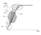
도 8a는 입력 영상의 휘도를 히스토그램화하여 표시한 도면이다.8A is a view showing the histogram of luminance of an input image.
도면을 참조하면, 입력 영상의 휘도 분포가 도면과 같이 예시될 수 있다.Referring to the drawings, the luminance distribution of the input image may be illustrated as illustrated.
제어부(170)는, 제1 기준치(Refa) 이상인, Lub 휘도에 해당하는 영역을, 제1 피크 영역으로 설정할 수 있다.The
그리고, 제1 기준치(Refa) 미만이며, 제2 기준치(refb) 이상인, Lua 휘도에 해당하는 영역을, 제2 피크 영역으로 설정할 수 있다.Further, a region corresponding to Lua luminance, which is less than the first reference value Refa and is greater than or equal to the second reference value refb, may be set as the second peak region.
한편, 도면을 참조하면, Lub 휘도의 경우, 인접하는 휘도의 차이가, DFb이며, Lua 휘도의 경우, Lua 휘도 보다 작으며 인접하는 휘도와의 차이가, DFa로서, DFb 보다 작은 것을 알 수 있다.On the other hand, referring to the drawings, in the case of Lub luminance, the difference between adjacent luminances is DFb, and in the case of Lua luminance, it can be seen that the difference between adjacent luminances is smaller than Lua luminance and smaller than DFb as DFa. .
한편, 제어부(170)는, 하이 다이나믹 레인지의 구현을 위해, 입력 영상에 대한 휘도 변환을, 도 8b와 같이 수행할 수 있다.Meanwhile, in order to realize a high dynamic range, the
도 8b는, 제1 커브(Cva)에 기초한 휘도 변환과, 제2 커브(Cvb)에 기초한 휘도 변환을 예시한다.8B illustrates luminance conversion based on the first curve Cva and luminance conversion based on the second curve Cvb.
먼저, 제1 커브(Cva)에 기초한 휘도 변환시, Lub 휘도에 대응하는 제1 피크 영역은, Lm2로 변환될 수 있으며, Lua 휘도에 대응하는 제2 피크 영역은, Lm2 보다 작은 Lm1으로 변환될 수 있다.First, in the luminance conversion based on the first curve Cva, the first peak region corresponding to Lub luminance may be converted to Lm2, and the second peak region corresponding to Lua luminance may be converted to Lm1 smaller than Lm2. have.
다음, 제2 커브(Cvb)에 기초한 휘도 변환시, Lub 휘도에 대응하는 제1 피크 영역은, 일정한 레벨인 Lm4로 변환될 수 있으며, Lua 휘도에 대응하는 제2 피크 영역은, Lm4 보다 작은 Lm3으로 변환될 수 있다.Next, when converting the luminance based on the second curve Cvb, the first peak region corresponding to the Lub luminance may be converted to a constant level Lm4, and the second peak region corresponding to the Lua luminance may be Lm3 smaller than Lm4. Can be converted.
즉, 제2 커브(Cvb)에 따르면, 제1 피크 영역은, 휘도 변환시, 포화 레벨인 Lm4로 일정하게 변환되나, 제2 피크 영역은, Lm3으로 변환되며, 이에 따라, 휘도 변화량이, 제1 피크 영역의 휘도 변화량 보다 크게 된다. 따라서, 제2 피크 영역의 휘도 표현력이 상당히 강화되게 된다.That is, according to the second curve Cvb, the first peak region is constantly converted to the saturation level Lm4 when the luminance is converted, but the second peak region is converted to the Lm3, and accordingly, the luminance change amount is the first It becomes larger than the luminance change amount of the peak area. Therefore, the luminance expression of the second peak region is significantly enhanced.
한편, 제1 커브(Cva)와 제2 커브(Cvb)를 비교하면, Lub 휘도의 휘도 변환시, 제1 커브(Cva) 대비 제2 커브(Cvb)에서의 휘도 변화량은, DFFb로 향상되며, Lua 휘도의 휘도 변환시, 제1 커브(Cva) 대비 제2 커브(Cvb)에서의 휘도 변화량은, DFFa로 향상된다. 특히, DFFa의 변화량이, DFFb 보다 크게 된다.On the other hand, when comparing the first curve Cva and the second curve Cvb, when the luminance of Lub luminance is converted, the luminance change amount in the second curve Cvb compared to the first curve Cva is improved to DFFb, and Lua When the luminance is converted, the amount of change in luminance in the second curve Cvb compared to the first curve Cva is improved to DFFa. In particular, the change amount of DFFa becomes larger than DFFb.
따라서, 제2 커브(Cvb)에 따른 휘도 변환시, 제1 커브(Cva) 대비하여, 제1 피크 영역과 제2 피크 영역의 휘도 표현력이 증대되며, 특히, 제2 피크 영역의 휘도 변화량이, 제1 피크 영역의 휘도 변화량 보다 크므로, 제2 피크 영역의 휘도 표현력이 증대되게 된다.Accordingly, when the luminance is converted according to the second curve Cvb, the luminance expressive power of the first peak region and the second peak region is increased compared to the first curve Cva. Since it is larger than the amount of change in luminance in one peak region, the luminance expression power in the second peak region is increased.
한편, 도 8c는, 제1 커브(Cvc)에 기초한 컨트라스트 변화와, 제2 커브(Cvd)에 기초한 컨트라스트 변화를 예시한다. 도 8c의 가로축은, 휘도이고, 세로축은 컨트라스트 레벨일 수 있다.Meanwhile, FIG. 8C illustrates contrast changes based on the first curve Cvc and contrast changes based on the second curve Cvd. The horizontal axis in FIG. 8C is luminance, and the vertical axis may be a contrast level.
도면을 참조하면, 제1 커브(Cvc) 대비, 제2 커브(Cvd)에서, 고 휘도 영역에서, 컨트라스트가 향상되는 것을 알 수 있다. 특히, 도 8b 등에서 설명한, Lub 휘도에 대응하는 제1 피크 영역과, Lua 휘도에 대응하는 제2 피크 영역에서, 컨트라스트가 향상될 수 있다.Referring to the drawing, it can be seen that contrast is improved in the high luminance region in the second curve Cvd, compared to the first curve Cvc. In particular, the contrast can be improved in the first peak region corresponding to Lub luminance and the second peak region corresponding to Lua luminance, described in FIG. 8B and the like.
도 9a는 입력 영상(810)의 일예를 도시한 도면이고, 도 9b는 입력 영상(810) 내의 제1 피크 영역(Arpa)과 제2 피크 영역(Arpb)이 검출되는 것을 예시하는 도면이다.9A is a diagram illustrating an example of the
한편, 제어부(170)는, 입력 영상 내의 피크 휘도의 차이가 제3 기준치 이내인 경우, 해당 영역을 제2 피크 영역(Arpb)으로 검출할 수 있다. Meanwhile, when the difference in peak luminance in the input image is within a third reference value, the
예를 들어, 제어부(170)는, 입력 영상을 소정 단위로 피크(peak)를 연산하고, 연산된 피크별 히스토그램을 통해, 인접하는 피크와의 레벨 차이가 제3 기준치 이내인 경우, 해당 영역을, 제2 피크 영역(Arpb)으로 검출할 수 있다. For example, the
즉, 제어부(170)는, 피크와의 레벨 차이가 제3 기준치 이내인 피크를 가지는 영역을, 제2 피크 영역(Arpb)으로 검출할 수 있다. 이에 따라, 제2 피크 영역(Arpb)을 용이하게 검출할 수 있게 된다.That is, the
한편, 도 9c는 도 8b의 제1 커브(Cva)에 기초하여 휘도 변환된 영상(820)을 도시한 도면이다.Meanwhile, FIG. 9C is a diagram illustrating an
다음, 도 9d는 도 8b의 제2 커브(Cvb)에 기초하여 휘도 변환된 영상(830)을 도시한 도면이다.Next, FIG. 9D is a diagram illustrating an
제어부(170)는, 휘도 변환시, 제1 피크 영역(Arpa)에 대해 제1 휘도 레벨로 변환하며, 제2 피크 영역(Arpb)에 대한 휘도를 증가시키도록 제어하고, 휘도 변환된 영상(830)을, 도 9d와 같이, 디스플레이(180)에 표시되도록 제어할 수 있다. 이에 따라, 영상 표시시 휘도 및 컨트라스트를 강화할 수 있게 된다.When the luminance is converted, the
특히, 도 9c의 영상(820)에 대비하여, 도 9d의 영상(830)의 제2 피크 영역(Arpb)에 대한 휘도 표현력 및 컨트라스트 표현력이 강화되게 된다. In particular, in contrast to the
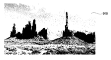
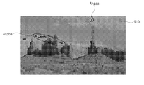
도 10a는 입력 영상(910)의 다른 예를 도시한 도면이고, 도 10b는 입력 영상(910) 내의 제1 피크 영역(Arpaa)과 제2 피크 영역(Arpba)이 검출되는 것을 예시하는 도면이다.10A is a diagram illustrating another example of the
다음, 도 10c는 도 8b의 제2 커브(Cvb)에 기초하여 휘도 변환된 영상(920)을 도시한 도면이다.Next, FIG. 10C is a diagram illustrating an
제어부(170)는, 휘도 변환시, 제1 피크 영역(Arpaa)에 대해 제1 휘도 레벨로 변환하며, 제2 피크 영역(Arpba)에 대한 휘도를 증가시키도록 제어하고, 휘도 변환된 영상(920)을, 도 10d와 같이, 디스플레이(180)에 표시되도록 제어할 수 있다. 이에 따라, 영상 표시시 휘도 및 컨트라스트를 강화할 수 있게 된다. 특히, 도 10c의 영상(920)의 제2 피크 영역(Arpba)에 대한 휘도 표현력 및 컨트라스트 표현력이 강화되게 된다. When the luminance is converted, the
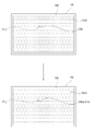
도 11a는 화질 설정 화면을 도시한 도면이다.11A is a diagram illustrating a picture quality setting screen.
도면을 참조하면, 제어부(170)는, 원격제어장치(200)의 메뉴 항목 선택시, 메뉴 화면이 표시되도록 제어하며, 메뉴 화면 내의 화질 설정 항목 선택시, 도면과 같이, 디스플레이(180)에 화질 설정 화면(1110)이 표시되도록 제어할 수 있다.Referring to the drawing, when the menu item of the
화질 설정 화면(1110)은, 컨트라스트 설정을 위한 다이나믹 컨트라스트 항목, 휘도 설정을 위한 다이나믹 톤 매핑 항목(1115), 해상도 설정을 위한 슈퍼 해상도 항목, 컬러 가뭇 설정을 위한 컬러 가뭇(gamut) 항목, 컬러 설정을 위한 컬러 필터 항목, 감마 설정을 위한 감마 항목 등을 구비할 수 있다.The image
제어부(170)는, 원격제어장치(200)의 버튼 입력 또는, 원격제어장치(200)의 움직임에 대응하여 표시되는 포인터(205)에 의한 선택 입력에 기초하여, 다이나믹 톤 매핑 항목(1115)이 선택되는 경우, 도 11b와 같이, 휘도 설정을 위한 다이나믹 톤 매핑 화면(1120)이 표시되도록 제어할 수 있다.The
한편, 다이나믹 톤 매핑 화면(1120)은, 도면과 같이, 제1 기준치(Refa)의 레벨 설정을 위한 제1 기준치 항목(1122)과, 제2 기준치(Refb)의 레벨 설정을 위한 제2 기준치 항목(1124)을 구비할 수 있다.Meanwhile, as shown in the drawing, the dynamic
제어부(170)는, 원격제어장치(200)의 버튼 입력 또는, 원격제어장치(200)의 움직임에 대응하여 표시되는 포인터(205)에 기초하여, 제1 기준치 항목(1122)을 선택하고, 제1 기준치에 대한 레벨을 가변할 수 있다. 이에 따라, 사용자 취향에 맞는, 휘도 및 컨트라스트 설정이 가능하게 된다.The
도 11b는, 원격제어장치(200)의 움직임에 대응하여 표시되는 포인터(205)의 좌측 이동에 따라, 제1 기준치 항목(1122)이 좌측으로 이동하는 것을 예시한다. 이에 따라, 제어부(170)는, 제1 기준치(Refa)의 레벨이 낮아지도록 제어할 수 있다.11B illustrates that the first
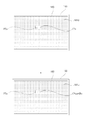
도 12a는 입력 영상의 휘도 분포 도면을 예시하며, 도 11b의 제1 기준치 항목(1122)이 좌측으로 이동함에 따라, 제1 기준치의 레벨이, Refa에서 Refaa로 낮아지는 것을 예시한다.12A illustrates a luminance distribution diagram of an input image, and illustrates that as the first
한편, 제어부(170)는, 제1 기준치(Refa)의 레벨이 낮아질수록, 상술한 제1 피크 영역의 사이즈가 확장되며, 사이즈 확장된 제1 피크 영역에 대해, 제1 휘도 레벨(Lma4)로 변환하도록 제어할 수 있다. 이에 따라, 휘도 변환시 포화되는 영역이 증가하게 된다.Meanwhile, as the level of the first reference value Refa is lowered, the
한편, 제어부(170)는, 원격제어장치(200)의 버튼 입력 또는, 원격제어장치(200)의 움직임에 대응하여 표시되는 포인터(205)에 기초하여, 제2 기준치 항목(1124)을 선택하고, 제2 기준치(Refb)에 대한 레벨을 가변할 수 있다. 이에 따라, 사용자 취향에 맞는, 휘도 및 컨트라스트 설정이 가능하게 된다.Meanwhile, the
도 11b는, 원격제어장치(200)의 움직임에 대응하여 표시되는 포인터(205)의 좌측 이동에 따라, 제2 기준치 항목(1124)이 좌측으로 이동하는 것을 예시한다. 이에 따라, 제어부(170)는, 제2 기준치(Reba)의 레벨이 낮아지도록 제어할 수 있다.11B illustrates that the second
도 12b는 입력 영상의 휘도 분포 도면을 예시하며, 도 11b의 제2 기준치 항목(1124)이 좌측으로 이동함에 따라, 제2 기준치의 레벨이, Refb에서 Refba로 낮아지는 것을 예시한다.FIG. 12B illustrates a luminance distribution diagram of an input image, and as the second
이에 따라, 제2 피크 영역에 대응하는 휘도 레벨은, Lua 외에, Lua2, Lua3가 더 포함되게 된다. Accordingly, in addition to Lua, Lua2 and Lua3 are further included in the luminance level corresponding to the second peak region.
제어부(170)는, 제2 기준치의 레벨이 낮아질수록, 상술한 제2 피크 영역의 사이즈가 확장되며, 사이즈 확장된 제2 피크 영역에 대해, 휘도를 증가시키도록 제어할 수 있다. 이에 따라, 해당 계조 영역에 대한 휘도 및 컨트라스트를 강화할 수 있게 된다.The
한편, 제어부(170)는, 프레임 단위 또는 씬(scene) 단위의 평균 휘도 레벨(Average Picture level; APL)을 연산하고, 평균 휘도 레벨에 따라, 제2 피크 영상의 휘도 증가량이 가변되도록 제어할 수 있다. 이에 따라, 평균 휘도 레벨에 대응하여, 영상 표시시 휘도 및 컨트라스트를 강화할 수 있게 된다.Meanwhile, the
한편, 제어부(170)는, 평균 휘도 레벨이 높을수록, 제2 피크 영상의 휘도 증가량이 작아지도록 제어할 수 있다. 이에 따라, 소비 전력을 고려하면서, 영상 표시시 휘도 및 컨트라스트를 강화할 수 있게 된다. 이에 대해서는 도 13a 내지 도 13b를 참조하여 기술한다.Meanwhile, the
먼저, 도 13a는, 입력 영상의 휘도 변환시, 복수의 커브에 기초하여, 휘도 변환이 수행되는 것을 예시한다.First, FIG. 13A illustrates that luminance conversion is performed based on a plurality of curves during luminance conversion of an input image.
제어부(170)는, 입력 영상에 대해, 프레임 단위 또는 씬(scene) 단위의 평균 휘도 레벨(Average Picture level; APL)을 연산하고, 평균 휘도 레벨에 따라, 휘도 변환 커브를 가변할 수 있다.The
예를 들어, 제어부(170)는, APL이 가장 높은 경우, 도 13a의 CAPa의 커브에 기초하여 휘도 변환을 수행하도록 제어하고, APL이 가장 낮은 경우, 도 13a의 CAPm의 커브에 기초하여 휘도 변환을 수행하도록 제어할 수 있다.For example, the
도면에 따르면, 제어부(170)는, 평균 휘도 레벨이 높을수록, 제2 피크 영상의 휘도 증가량이 작아지도록 제어할 수 있다. 이에 따라, 소비 전력을 고려하면서, 영상 표시시 휘도 및 컨트라스트를 강화할 수 있게 된다.According to the drawing, the
한편, 제어부(170)는, 휘도 변환시, LVa 보다 낮은 저계조 영역(Pa), LVa와 LVb 사이의 중계조 영역(Pb), LVb 초과의 고계조 영역(Pc)으로 분리하고, 저계조 영역(Pa)에 대비하여, 중계조 영역(Pb)의 휘도 변화량이 낮아지며, 중계조 영역(Pb) 보다 고계조 영역(Pc)의 휘도 변화량이 작아지도록 제어할 수 있다.On the other hand, when the luminance is converted, the
특히, 제어부(170)는, 중계조 영역(Pb)에서, 비선형 스케일링에 따라, 휘도 변환이 수행되도록 제어할 수 있다. 이에 따라, 중계조 영역(Pb)의 휘도 표현력의 증대가 가능하게 된다.In particular, the
도 13b는 APL 대비 휘도 곡선을 도시하는 도면이다.13B is a diagram showing a luminance curve compared to APL.
도면을 참조하면, 영상표시장치(100) 중 유기발광패널(210)을 구비하는 영상표시의 경우, 자발광 소자이므로, 영상 표시시, 소비 전력 저감 등을 위해, APL 구동을 수행할 수 있다.Referring to the drawing, in the case of an image display including the organic
여기서, APL 구동은, 도면과 같이, APL이 커질수록, 휘도가 낮아지도록 제어하며, APL이 작아질수록 휘도가 높아지는 것을 나타낸다.Here, the APL driving, as shown in the drawing, controls that the luminance increases as the APL increases, and that the luminance increases as the APL decreases.
도면에서는, APLa의 경우, LLa의 휘도로 구동되며, APLa 보다 작은 Apm의 경우, LLa 보다 큰 LLb의 휘도로 구동되는 것을 예시한다.In the drawing, it is illustrated that in the case of APLa, it is driven with the luminance of LLa, and in the case of Apm that is smaller than APLa, it is driven with the luminance of LLb larger than LLa.
이에 따라, 제어부(170)는, 평균 휘도 레벨이 높을수록, 제2 피크 영상의 휘도 증가량이 작아지도록 제어할 수 있다. 이에 따라, 소비 전력을 고려하면서, 영상 표시시 휘도 및 컨트라스트를 강화할 수 있게 된다.Accordingly, the
또한, 제어부(170)는, 평균 휘도 레벨이 높을수록, 제1 피크 영상의 휘도 증가량이 작아지도록 제어할 수 있다. 이에 따라, 소비 전력을 고려하면서, 영상 표시시 휘도 및 컨트라스트를 강화할 수 있게 된다.Also, the
도 14a는 입력 영상(1110)을 예시하고, 도 14b는, 13a와 도 13b의 APL 구동 및 휘도 변환이 수행되어, 영상의 밝기, 휘도 및 컨트라스트가 개선된 영상(1120)을 예시하는 도면이다.14A illustrates an
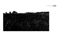
다음, 도 15a는 입력 영상(1210)을 예시하고, 도 15b는, 13a와 도 13b의 APL 구동 및 휘도 변환이 수행되어, 영상의 밝기, 휘도 및 컨트라스트가 개선된 영상(1220)을 예시하는 도면이다.Next, FIG. 15A illustrates an
특히, 영상(1220) 내의 제1 영역(1222)에 대한, 영상의 밝기, 휘도 및 컨트라스트가 개선되며, 영상(1220) 내의 제2 영역(1224)에 대한, 컬러 및 컨트라스트가 개선될 수 있다In particular, for the
한편, 제어부(170)는, 순차적으로 작아지는 패턴을 가지는 영상이 순차적으로 수신되는 상태에서, 패턴의 사이즈가 기준 사이즈 이상인 경우, 패턴의 휘도를 증가시키며, 패턴의 사이즈가 기준 사이즈 미만인 경우, 패턴의 휘도를 일정 레벨로 유지하거나, 패턴의 휘도를 그대로 유지하도록 제어할 수 있다. 이에 따라, 전체 영상 대비 패턴 사이즈에 따라, 휘도 변환을 달리하므로, 입력 영상에 대한 최적의 휘도 및 컨트라스트 표현이 가능하게 된다. 이에 대해서는 도 16a 내지 도 16c를 참조하여 기술한다.Meanwhile, the
먼저, 도 16a는 입력 영상(1610) 내의 패턴(PTa)의 사이즈가 제1 사이즈인 것을 예시한다.First, FIG. 16A illustrates that the size of the pattern PTa in the
제어부(170)는, 입력 영상(1610)에 대해, 패턴(PTa)의 사이즈가, 기준 사이즈 이상인 제1 사이즈인 경우, 패턴의 휘도를 증가시켜, GRa의 휘도를 Graa로 증가되도록 제어할 수 있다.The
이에 의하면, 입력 영상(1610) 내의 패턴(PTa)은, 상술한 제2 피크 영역에 대응할 수 있으며, 따라서, 제어부(170)는, 휘도가 증가하도록 제어할 수 있다.According to this, the pattern PTa in the
다음, 도 16b는 입력 영상(1620) 내의 패턴(PTb)의 사이즈가 제2 사이즈인 것을 예시한다.Next, FIG. 16B illustrates that the size of the pattern PTb in the
제어부(170)는, 입력 영상(1620)에 대해, 패턴(PTb)의 사이즈가, 도 16a의 제1 사이즈 보다 작으나, 기준 사이즈 이상인 제2 사이즈인 경우, 패턴의 휘도를 증가시켜, GRb의 휘도를 Grba로 증가되도록 제어할 수 있다.When the size of the pattern PTb is smaller than the first size in FIG. 16A, but the second size is greater than or equal to the reference size, the
이에 의하면, 입력 영상(1620) 내의 패턴(PTb)은, 상술한 제2 피크 영역에 대응할 수 있으며, 따라서, 제어부(170)는, 휘도가 증가하도록 제어할 수 있다. 특히, 휘도 증가량은, 도 16a에 비해, 더 클 수 있다. According to this, the pattern PTb in the
다음, 도 16c는 입력 영상(1630) 내의 패턴(PTb)의 사이즈가 제3 사이즈인 것을 예시한다.Next, FIG. 16C illustrates that the size of the pattern PTb in the
제어부(170)는, 입력 영상(1630)에 대해, 패턴(PTc)의 사이즈가, 도 16b의 제2 사이즈 보다 작으며, 기준 사이즈 미만인 제3 사이즈인 경우, 패턴의 휘도를 변화시키지 않고, GRc의 휘도를 Grc로 그대로 유지되도록 제어할 수 있다.When the size of the pattern PTc is smaller than the second size of FIG. 16B and less than the reference size for the
이에 의하면, 입력 영상(1630) 내의 패턴(PTc)은, 상술한 제1 피크 영역에 대응할 수 있으며, 따라서, 제어부(170)는, 일정한 레벨의 휘도로 변환하거나, 변화 없이, 입력 휘도를 그대로 유지하도록 제어할 수 있다. According to this, the pattern PTc in the
이에 따라, 전체 영상 대비 패턴 사이즈에 따라, 휘도 변환을 달리하므로, 입력 영상에 대한 최적의 휘도 및 컨트라스트 표현이 가능하게 된다.Accordingly, since luminance conversion is different according to the pattern size compared to the entire image, it is possible to optimally express luminance and contrast for the input image.
한편, 본 발명의 영상표시장치의 동작방법은, 영상표시장치에 구비된 프로세서가 읽을 수 있는 기록매체에 프로세서가 읽을 수 있는 코드로서 구현하는 것이 가능하다. 프로세서가 읽을 수 있는 기록매체는 프로세서에 의해 읽혀질 수 있는 데이터가 저장되는 모든 종류의 기록장치를 포함한다. 프로세서가 읽을 수 있는 기록매체의 예로는 ROM, RAM, CD-ROM, 자기 테이프, 플로피디스크, 광 데이터 저장장치 등이 있으며, 또한, 인터넷을 통한 전송 등과 같은 캐리어 웨이브의 형태로 구현되는 것도 포함한다. 또한, 프로세서가 읽을 수 있는 기록매체는 네트워크로 연결된 컴퓨터 시스템에 분산되어, 분산방식으로 프로세서가 읽을 수 있는 코드가 저장되고 실행될 수 있다.On the other hand, the operation method of the video display device of the present invention can be implemented as a code readable by the processor on a recording medium readable by the processor provided in the video display device. The processor-readable recording medium includes all types of recording devices in which data that can be read by the processor are stored. Examples of the recording medium that can be read by the processor include ROM, RAM, CD-ROM, magnetic tape, floppy disk, optical data storage device, etc., and include those implemented in the form of carrier waves such as transmission through the Internet. . In addition, the processor-readable recording medium can be distributed over network coupled computer systems so that the processor-readable code is stored and executed in a distributed fashion.
또한, 이상에서는 본 발명의 바람직한 실시예에 대하여 도시하고 설명하였지만, 본 발명은 상술한 특정의 실시예에 한정되지 아니하며, 청구범위에서 청구하는 본 발명의 요지를 벗어남이 없이 당해 발명이 속하는 기술분야에서 통상의 지식을 가진자에 의해 다양한 변형실시가 가능한 것은 물론이고, 이러한 변형실시들은 본 발명의 기술적 사상이나 전망으로부터 개별적으로 이해되어져서는 안될 것이다.In addition, although the preferred embodiments of the present invention have been shown and described above, the present invention is not limited to the specific embodiments described above, and the technical field to which the present invention belongs without departing from the gist of the present invention claimed in the claims. In addition, various modifications can be implemented by those skilled in the art, and these modifications should not be individually understood from the technical idea or prospect of the present invention.
Claims (17)
상기 디스플레이를 제어하는 제어부;를 포함하고,
상기 제어부는,
입력 영상 내의 휘도 중 제1 기준치 이상인 제1 피크 영역을 검출하고, 상기 입력 영상 내의 휘도 중 상기 제1 기준치 미만이며 제2 기준치 사이의 제2 피크 영역을 검출하고, 휘도 변환시, 상기 제1 피크 영역에 대해 제1 휘도 레벨로 변환하며, 상기 제2 피크 영역에 대한 휘도를 증가시키도록 제어하고, 상기 휘도 변환된 영상을 상기 디스플레이에 표시되도록 제어하는 것을 특징으로 하는 영상표시장치.display;
Includes a control unit for controlling the display;
The control unit,
A first peak area of a luminance in an input image that is greater than or equal to a first reference value is detected, and a second peak region of the luminance in the input image that is less than the first reference value and between a second reference value is detected, and when the luminance is converted, the first peak region The image display apparatus is characterized in that for converting to a first luminance level, controlling to increase the luminance for the second peak region, and controlling the luminance-converted image to be displayed on the display.
상기 제어부는,
상기 제1 피크 영역의 휘도 변화량 보다, 상기 제2 피크 영역의 휘도 변화량이 더 커지도록 제어하는 것을 특징으로 하는 영상표시장치.According to claim 1,
The control unit,
An image display apparatus characterized in that the luminance change amount of the second peak region is controlled to be larger than the luminance change amount of the first peak region.
상기 제어부는,
상기 입력 영상 내의 피크 휘도의 차이가 제3 기준치 이내인 경우, 해당 영역을 상기 제2 피크 영역으로 검출하는 것을 특징으로 하는 영상표시장치.According to claim 1,
The control unit,
When the difference in peak luminance in the input image is within a third reference value, the image display apparatus is characterized in that the region is detected as the second peak region.
상기 제어부는,
프레임 단위 또는 씬(scene) 단위의 평균 휘도 레벨(Average Picture level; APL)을 연산하고, 상기 평균 휘도 레벨에 따라, 상기 제2 피크 영상의 휘도 증가량이 가변되도록 제어하는 것을 특징으로 하는 영상표시장치.According to claim 1,
The control unit,
An image display device comprising calculating an average luminance level (APL) in units of frames or scenes and controlling the amount of increase in luminance of the second peak image to vary according to the average luminance level .
상기 제어부는,
상기 평균 휘도 레벨이 높을수록, 상기 제2 피크 영상의 휘도 증가량이 작아지도록 제어하는 것을 특징으로 하는 영상표시장치.According to claim 4,
The control unit,
The higher the average luminance level is, the smaller the amount of increase in luminance of the second peak image is.
상기 제어부는,
설정 입력에 따라, 상기 제2 기준치의 레벨을 가변하는 것을 특징으로 하는 영상표시장치.According to claim 1,
The control unit,
A video display device characterized in that the level of the second reference value is varied according to a setting input.
상기 제어부는,
상기 제2 기준치의 레벨이 낮아질수록, 상기 제2 피크 영역의 사이즈가 확장되며, 상기 사이즈 확장된 제2 피크 영역에 대해, 휘도를 증가시키도록 제어하는 것을 특징으로 하는 영상표시장치.The method of claim 6,
The control unit,
The lower the level of the second reference value, the larger the size of the second peak area, the image display device, characterized in that for controlling to increase the luminance for the size of the expanded second peak area.
상기 제어부는,
설정 입력에 따라, 상기 제1 기준치의 레벨을 가변하는 것을 특징으로 하는 영상표시장치.According to claim 1,
The control unit,
A video display device characterized in that the level of the first reference value is varied according to a setting input.
상기 제어부는,
상기 제1 기준치의 레벨이 낮아질수록, 상기 제1 피크 영역의 사이즈가 확장되며, 상기 사이즈 확장된 제1 피크 영역에 대해, 상기 제1 휘도 레벨로 변환하도록 제어하는 것을 특징으로 하는 영상표시장치.The method of claim 8,
The control unit,
The lower the level of the first reference value, the larger the size of the first peak area, the image display device, characterized in that for controlling to convert the size of the expanded first peak area to the first luminance level.
상기 제어부는,
순차적으로 작아지는 패턴을 가지는 영상이 순차적으로 수신되는 상태에서, 상기 패턴의 사이즈가 기준 사이즈 이상인 경우, 상기 패턴의 휘도를 증가시키며, 상기 패턴의 사이즈가 기준 사이즈 미만인 경우, 상기 패턴의 휘도를 일정 레벨로 유지하거나, 상기 패턴의 휘도를 그대로 유지하도록 제어하는 것을 특징으로 하는 영상표시장치.According to claim 1,
The control unit,
When an image having a pattern that is sequentially reduced is sequentially received, when the size of the pattern is greater than or equal to a reference size, the brightness of the pattern is increased. When the size of the pattern is less than the reference size, the brightness of the pattern is constant. It is controlled to maintain the level or maintain the brightness of the pattern as it is, the image display device characterized in that.
상기 제어부는,
화질 설정 입력에 따라, 화질 설정을 위한 화질 설정 메뉴를 표시하도록 제어하고, 상기 화질 설정 메뉴 하의 다이나믹 톤 매핑 항목이 선택되는 경우, 휘도 가변을 위한 다이나믹 톤 매핑 화면을 표시하도록 제어하는 것을 특징으로 하는 영상표시장치.According to claim 1,
The control unit,
Controlling to display a quality setting menu for image quality setting according to an image quality setting input, and controlling to display a dynamic tone mapping screen for varying luminance when a dynamic tone mapping item under the image quality setting menu is selected. Video display device.
원격제어장치로부터 포인팅 신호를 수신하는 인터페이스부;를 더 포함하고,
상기 제어부는,
상기 다이나믹 톤 매핑 화면 내에, 상기 포인팅 신호에 대응하는 포인터를 표시하도록 제어하는 것을 특징으로 하는 영상표시장치.The method of claim 11,
Further comprising; an interface unit for receiving a pointing signal from the remote control device,
The control unit,
And displaying a pointer corresponding to the pointing signal in the dynamic tone mapping screen.
상기 다이나믹 톤 매핑 화면은,
상기 제1 기준치의 변경을 위한 제1 기준치 항목과, 상기 제2 기준치의 변경을 위한 제2 기준치 항목을 포함하고,
상기 제어부는,
상기 포인터의 이동에 따라, 상기 제1 기준치 항목 또는 상기 제2 기준치 항목의 설정이 가변되도록 제어하는 것을 특징으로 하는 영상표시장치.The method of claim 12,
The dynamic tone mapping screen,
A first reference value item for changing the first reference value, and a second reference value item for changing the second reference value,
The control unit,
An image display apparatus characterized in that the setting of the first reference value item or the second reference value item is controlled to be variable according to the movement of the pointer.
상기 제어부는,
상기 입력 영상 내의 휘도 중 상기 제2 기준치 이하의 영역에 대해, 비선형 스케일링에 따라 휘도가 가변되도록 제어하는 것을 특징으로 하는 영상표시장치.The method of claim 12,
The control unit,
An image display apparatus characterized in that the luminance in the input image is controlled to be variable in accordance with a non-linear scaling with respect to a region below the second reference value.
상기 디스플레이를 제어하는 제어부;를 포함하고,
상기 제어부는,
순차적으로 작아지는 패턴을 가지는 영상이 순차적으로 수신되는 경우, 상기 패턴의 사이즈가 기준 사이즈 이상인 경우, 상기 패턴의 휘도를 증가시키며, 상기 패턴의 사이즈가 기준 사이즈 미만인 경우, 상기 패턴의 휘도를 일정 레벨로 유지하거나, 상기 패턴의 휘도를 그대로 유지하도록 제어하는 제어부;를 포함하는 것을 특징으로 하는 영상표시장치.display;
Includes a control unit for controlling the display;
The control unit,
When an image having a pattern that is sequentially reduced is sequentially received, when the size of the pattern is greater than or equal to a reference size, the luminance of the pattern is increased. When the size of the pattern is less than the reference size, the luminance of the pattern is set to a certain level. Or a control unit for controlling to maintain the luminance of the pattern as it is.
상기 제어부는,
상기 패턴의 피크 휘도의 차이가 기준치 이내이며, 상기 패턴의 사이즈가 상기 기준 사이즈 이상인 경우, 상기 패턴의 휘도를 증가시키는 것을 특징으로 하는 영상표시장치.The method of claim 15,
The control unit,
When the difference in peak luminance of the pattern is within a reference value, and the size of the pattern is greater than or equal to the reference size, an image display device for increasing the luminance of the pattern.
상기 제어부는,
상기 패턴의 피크 휘도의 차이가 기준치 초과이며, 상기 패턴의 사이즈가 상기 기준 사이즈 미만인 경우, 상기 패턴의 휘도를 일정 레벨로 유지하거나, 상기 패턴의 휘도를 그대로 유지하도록 제어하는 것을 특징으로 하는 영상표시장치.
The method of claim 15,
The control unit,
When the difference in peak luminance of the pattern is greater than a reference value, and the size of the pattern is less than the reference size, the luminance of the pattern is maintained at a constant level, or the display is controlled to maintain the luminance of the pattern as it is. Device.
Priority Applications (4)
| Application Number | Priority Date | Filing Date | Title |
|---|---|---|---|
| KR1020180111807A KR20200032584A (en) | 2018-09-18 | 2018-09-18 | Image display apparatus |
| PCT/KR2019/012062 WO2020060186A1 (en) | 2018-09-18 | 2019-09-18 | Image display device |
| EP19863299.4A EP3855730A4 (en) | 2018-09-18 | 2019-09-18 | Image display device |
| US17/277,225 US11532289B2 (en) | 2018-09-18 | 2019-09-18 | Image display apparatus |
Applications Claiming Priority (1)
| Application Number | Priority Date | Filing Date | Title |
|---|---|---|---|
| KR1020180111807A KR20200032584A (en) | 2018-09-18 | 2018-09-18 | Image display apparatus |
Publications (1)
| Publication Number | Publication Date |
|---|---|
| KR20200032584A true KR20200032584A (en) | 2020-03-26 |
Family
ID=69888573
Family Applications (1)
| Application Number | Title | Priority Date | Filing Date |
|---|---|---|---|
| KR1020180111807A KR20200032584A (en) | 2018-09-18 | 2018-09-18 | Image display apparatus |
Country Status (4)
| Country | Link |
|---|---|
| US (1) | US11532289B2 (en) |
| EP (1) | EP3855730A4 (en) |
| KR (1) | KR20200032584A (en) |
| WO (1) | WO2020060186A1 (en) |
Cited By (1)
| Publication number | Priority date | Publication date | Assignee | Title |
|---|---|---|---|---|
| US11580899B1 (en) | 2022-01-03 | 2023-02-14 | Lg Electronics Inc. | Display device |
Families Citing this family (2)
| Publication number | Priority date | Publication date | Assignee | Title |
|---|---|---|---|---|
| US11756505B2 (en) * | 2020-03-31 | 2023-09-12 | Apple Inc. | Peak luminance control to enable higher display brightness |
| US20240013697A1 (en) * | 2022-07-05 | 2024-01-11 | Samsung Electronics Co., Ltd. | Display apparatus and control method thereof |
Family Cites Families (19)
| Publication number | Priority date | Publication date | Assignee | Title |
|---|---|---|---|---|
| JP2006101421A (en) | 2004-09-30 | 2006-04-13 | Toshiba Corp | Video signal processing circuit |
| JP4372747B2 (en) * | 2005-01-25 | 2009-11-25 | シャープ株式会社 | Luminance level conversion device, luminance level conversion method, solid-state imaging device, luminance level conversion program, and recording medium |
| KR100743758B1 (en) * | 2005-09-05 | 2007-07-30 | 엘지전자 주식회사 | Apparatus and Method for controlling dynamic contrast ratio using peak level |
| KR20070120795A (en) * | 2006-06-20 | 2007-12-26 | 삼성전자주식회사 | Display apparatus and control method thereof |
| JP4513891B2 (en) * | 2008-04-09 | 2010-07-28 | ソニー株式会社 | VIDEO SIGNAL PROCESSING DEVICE, IMAGING DEVICE, VIDEO SIGNAL PROCESSING METHOD, AND PROGRAM |
| JP5284444B2 (en) * | 2011-11-11 | 2013-09-11 | シャープ株式会社 | Video display device and television receiver |
| KR102158831B1 (en) * | 2014-04-29 | 2020-09-22 | 한화테크윈 주식회사 | Imaging Device including Image Signal Processing |
| CN110992914B (en) * | 2014-10-06 | 2022-07-01 | 三星电子株式会社 | Display apparatus and method of controlling the same |
| JP6365355B2 (en) * | 2015-03-09 | 2018-08-01 | オムロン株式会社 | Image generating apparatus and image generating method |
| WO2016182307A1 (en) * | 2015-05-11 | 2016-11-17 | 삼성전자 주식회사 | Image processing apparatus and image processing method based on metadata |
| US9942489B2 (en) * | 2015-06-02 | 2018-04-10 | Samsung Electronics Co., Ltd. | Adaptive tone mapping based on local contrast |
| CA2999098A1 (en) * | 2015-09-25 | 2017-03-30 | Sony Corporation | Image processing apparatus and image processing method |
| US10863201B2 (en) * | 2015-12-21 | 2020-12-08 | Koninklijke Philips N.V. | Optimizing high dynamic range images for particular displays |
| WO2018132329A1 (en) * | 2017-01-10 | 2018-07-19 | Dolby Laboratories Licensing Corporation | Display mapping for high dynamic range images |
| US10403233B2 (en) * | 2017-01-17 | 2019-09-03 | Canon Kabushiki Kaisha | Image processing apparatus and image processing method |
| US10176561B2 (en) | 2017-01-27 | 2019-01-08 | Microsoft Technology Licensing, Llc | Content-adaptive adjustments to tone mapping operations for high dynamic range content |
| US11100888B2 (en) * | 2017-06-28 | 2021-08-24 | The University Of British Columbia | Methods and apparatuses for tone mapping and inverse tone mapping |
| EP3684061B1 (en) * | 2017-09-13 | 2021-07-07 | Panasonic Intellectual Property Management Co., Ltd. | Video display device and video display method |
| US10546554B2 (en) * | 2018-03-26 | 2020-01-28 | Dell Products, Lp | System and method for adaptive tone mapping for high dynamic ratio digital images |
-
2018
- 2018-09-18 KR KR1020180111807A patent/KR20200032584A/en active Search and Examination
-
2019
- 2019-09-18 WO PCT/KR2019/012062 patent/WO2020060186A1/en unknown
- 2019-09-18 EP EP19863299.4A patent/EP3855730A4/en active Pending
- 2019-09-18 US US17/277,225 patent/US11532289B2/en active Active
Cited By (1)
| Publication number | Priority date | Publication date | Assignee | Title |
|---|---|---|---|---|
| US11580899B1 (en) | 2022-01-03 | 2023-02-14 | Lg Electronics Inc. | Display device |
Also Published As
| Publication number | Publication date |
|---|---|
| US20220028353A1 (en) | 2022-01-27 |
| US11532289B2 (en) | 2022-12-20 |
| EP3855730A4 (en) | 2022-06-29 |
| WO2020060186A1 (en) | 2020-03-26 |
| EP3855730A1 (en) | 2021-07-28 |
Similar Documents
| Publication | Publication Date | Title |
|---|---|---|
| KR102370442B1 (en) | Image display apparatus | |
| KR102661825B1 (en) | Signal processing device and image display apparatus including the same | |
| US11532289B2 (en) | Image display apparatus | |
| US11315522B2 (en) | Image display apparatus | |
| KR20210026293A (en) | Image display apparatus | |
| US20220375425A1 (en) | Signal processing device and image display apparatus including same | |
| KR102390902B1 (en) | Image display apparatus | |
| KR102366403B1 (en) | Image display apparatus | |
| KR102603620B1 (en) | Image display apparatus | |
| CN111757078B (en) | Signal processing device and image display apparatus including the same | |
| KR102570381B1 (en) | organic light emitting diode display | |
| KR102588780B1 (en) | Organic light emitting diode display device | |
| US11335255B2 (en) | Signal processing device and image display apparatus including the same | |
| US20220139310A1 (en) | Signal processing device and image display apparatus including the same | |
| US11881149B2 (en) | Signal processing device and image display device comprising same | |
| KR102591383B1 (en) | Organic light emitting diode display device | |
| US11961262B2 (en) | Signal processing apparatus and image display apparatus including same | |
| KR20200125060A (en) | Signal processing device and image display apparatus including the same |
Legal Events
| Date | Code | Title | Description |
|---|---|---|---|
| A201 | Request for examination |