KR20190128807A - System furniture structure - Google Patents
System furniture structure Download PDFInfo
- Publication number
- KR20190128807A KR20190128807A KR1020180052954A KR20180052954A KR20190128807A KR 20190128807 A KR20190128807 A KR 20190128807A KR 1020180052954 A KR1020180052954 A KR 1020180052954A KR 20180052954 A KR20180052954 A KR 20180052954A KR 20190128807 A KR20190128807 A KR 20190128807A
- Authority
- KR
- South Korea
- Prior art keywords
- fastening
- post frame
- bracket
- system furniture
- center
- Prior art date
Links
- 230000008878 coupling Effects 0.000 claims abstract description 15
- 238000010168 coupling process Methods 0.000 claims abstract description 15
- 238000005859 coupling reaction Methods 0.000 claims abstract description 15
- 238000005192 partition Methods 0.000 claims description 12
- 238000003780 insertion Methods 0.000 claims description 9
- 230000037431 insertion Effects 0.000 claims description 9
- 238000000034 method Methods 0.000 claims description 5
- 230000000694 effects Effects 0.000 abstract description 5
- 238000012986 modification Methods 0.000 description 4
- 230000004048 modification Effects 0.000 description 4
- 210000000038 chest Anatomy 0.000 description 1
- 238000007796 conventional method Methods 0.000 description 1
- 238000004519 manufacturing process Methods 0.000 description 1
Images


Classifications
-
- A—HUMAN NECESSITIES
- A47—FURNITURE; DOMESTIC ARTICLES OR APPLIANCES; COFFEE MILLS; SPICE MILLS; SUCTION CLEANERS IN GENERAL
- A47B—TABLES; DESKS; OFFICE FURNITURE; CABINETS; DRAWERS; GENERAL DETAILS OF FURNITURE
- A47B96/00—Details of cabinets, racks or shelf units not covered by a single one of groups A47B43/00 - A47B95/00; General details of furniture
- A47B96/14—Bars, uprights, struts, or like supports, for cabinets, brackets, or the like
- A47B96/1466—Bars, uprights, struts, or like supports, for cabinets, brackets, or the like with longitudinal grooves
-
- A—HUMAN NECESSITIES
- A47—FURNITURE; DOMESTIC ARTICLES OR APPLIANCES; COFFEE MILLS; SPICE MILLS; SUCTION CLEANERS IN GENERAL
- A47B—TABLES; DESKS; OFFICE FURNITURE; CABINETS; DRAWERS; GENERAL DETAILS OF FURNITURE
- A47B87/00—Sectional furniture, i.e. combinations of complete furniture units, e.g. assemblies of furniture units of the same kind such as linkable cabinets, tables, racks or shelf units
- A47B87/02—Sectional furniture, i.e. combinations of complete furniture units, e.g. assemblies of furniture units of the same kind such as linkable cabinets, tables, racks or shelf units stackable ; stackable and linkable
- A47B87/0207—Stackable racks, trays or shelf units
- A47B87/0223—Shelves stackable by means of poles or tubular members as distance-holders therebetween
-
- A—HUMAN NECESSITIES
- A47—FURNITURE; DOMESTIC ARTICLES OR APPLIANCES; COFFEE MILLS; SPICE MILLS; SUCTION CLEANERS IN GENERAL
- A47B—TABLES; DESKS; OFFICE FURNITURE; CABINETS; DRAWERS; GENERAL DETAILS OF FURNITURE
- A47B96/00—Details of cabinets, racks or shelf units not covered by a single one of groups A47B43/00 - A47B95/00; General details of furniture
- A47B96/06—Brackets or similar supporting means for cabinets, racks or shelves
-
- E—FIXED CONSTRUCTIONS
- E06—DOORS, WINDOWS, SHUTTERS, OR ROLLER BLINDS IN GENERAL; LADDERS
- E06B—FIXED OR MOVABLE CLOSURES FOR OPENINGS IN BUILDINGS, VEHICLES, FENCES OR LIKE ENCLOSURES IN GENERAL, e.g. DOORS, WINDOWS, BLINDS, GATES
- E06B5/00—Doors, windows, or like closures for special purposes; Border constructions therefor
- E06B5/006—Doors, windows, or like closures for special purposes; Border constructions therefor for furniture
-
- F—MECHANICAL ENGINEERING; LIGHTING; HEATING; WEAPONS; BLASTING
- F16—ENGINEERING ELEMENTS AND UNITS; GENERAL MEASURES FOR PRODUCING AND MAINTAINING EFFECTIVE FUNCTIONING OF MACHINES OR INSTALLATIONS; THERMAL INSULATION IN GENERAL
- F16B—DEVICES FOR FASTENING OR SECURING CONSTRUCTIONAL ELEMENTS OR MACHINE PARTS TOGETHER, e.g. NAILS, BOLTS, CIRCLIPS, CLAMPS, CLIPS OR WEDGES; JOINTS OR JOINTING
- F16B12/00—Jointing of furniture or the like, e.g. hidden from exterior
- F16B12/10—Jointing of furniture or the like, e.g. hidden from exterior using pegs, bolts, tenons, clamps, clips, or the like
-
- A—HUMAN NECESSITIES
- A47—FURNITURE; DOMESTIC ARTICLES OR APPLIANCES; COFFEE MILLS; SPICE MILLS; SUCTION CLEANERS IN GENERAL
- A47B—TABLES; DESKS; OFFICE FURNITURE; CABINETS; DRAWERS; GENERAL DETAILS OF FURNITURE
- A47B2220/00—General furniture construction, e.g. fittings
- A47B2220/0036—Brackets
Landscapes
- Engineering & Computer Science (AREA)
- General Engineering & Computer Science (AREA)
- Civil Engineering (AREA)
- Structural Engineering (AREA)
- Mechanical Engineering (AREA)
- Assembled Shelves (AREA)
Abstract
Description
본 발명은 주거 공간 및 수납 공간의 효율적 활용성을 높이기 위한 시스템 가구의 구조에 관한 것으로, 기둥 역할을 수행하는 포스트프레임의 양 외측을 각각 감싸며 일정 영역을 커버하는 커버패널을 대향되도록 설치하고, 상기 커버패널의 내측을 연결하는 수납함 또는 선반 등의 부재가 연결되도록 구성하여, 시스템 가구의 조립이 용이하도록 하면서도, 견고성 확보가 가능하되 포스트프레임이 천정과 바닥면에 양단이 각각 접하며 고정되는 기존의 조립 형태에서 탈피하여 포스트프레임의 다양한 길이 적용이 가능하도록 하여, 견고성과 공간 활용성 및 실내 인테리어 효과를 극대화 시킬 수 있도록 하는 시스템 가구 구조에 관한 것이다.The present invention relates to a structure of a system furniture for increasing the efficient utilization of the living space and storage space, and covers the outer side of each of the post frame to serve as a pillar to install a cover panel to cover a predetermined area facing, Members such as storage boxes or shelves that connect the inside of the cover panel are connected to each other to facilitate the assembly of system furniture, while ensuring robustness, but the existing assembly where both ends of the postframe are fixed to the ceiling and the floor. The present invention relates to a system furniture structure that can be applied to various lengths of the post frame by deviating from the shape, thereby maximizing robustness, space utilization, and interior effect.
주거 공간내에서 인간의 생활을 영위하기 위해 필수적인 생활도구 중의 하나로 가구를 들 수 있는바, 보다 윤택하고 쾌적한 생활 공간의 연출을 위해 가구를 통하여 자신들의 주거 생활 이미지 또는 생활 양식을 구현하며 만족감을 얻을 수 있다. One of the essential tools for living a human life in a residential space is furniture, which provides a sense of satisfaction by embodying their living image or lifestyle through furniture to create a more pleasant and comfortable living space. Can be.
더욱이 현대에 이르러 개성화, 다양화되는 시대임을 반영하여 다양한 양식, 기호에 따라 실내 공간 연출의 욕구가 지대한바, 가구는 이러한 욕구를 실현하기 위한 수단으로 전환되고 있음은 주지된 바와 같다.In addition, it is well known that furniture needs to be transformed into a means for realizing such needs by reflecting that it is an era of individualization and diversification in modern times according to various styles and preferences.
즉, 오늘날의 가구 형태는 기존과 같이 옷장, 서랍장, 선반, 진열장, 책상 등 단일화된 제품으로 제작, 공급되는 형태에서 탈피하여 주거 공간내에서 인간의 생활을 원활하게 영위하며 각종 물품, 생활도구, 의류, 서재 등을 포함하는 물품의 용이한 수납 및 보관을 위하여 사용되는 도구 중의 하나인 가구를 시스템화하여 제작, 설치 시공되어 공급되고 있는 추세에 있다.In other words, today's furniture forms are separated from the ones that are manufactured and supplied as single products such as wardrobes, chests of drawers, shelves, showcases, and desks. There is a trend that systemized furniture, which is one of tools used for easy storage and storage of articles including clothing, study, and the like, is manufactured, installed, and supplied.
이러한 시스템가구는 전술한 바와 같이 장식장, 책장, 드레스룸, 서랍장, 붙박이장, 진열대 등 각종 가구류를 구성하도록 하기 위해 포스트와, 이 포스트를 고정하는 선반받침대 및 선반받침대에 고정되는 선반으로 구성되고, 상기 포스트의 상,하부는 실내의 바닥면과 천정면에 밀착되어 수직상 설치되는 구조를 갖게 된다.Such a system furniture is composed of a post, a shelf for fixing the post, and a shelf fixed to the shelf to configure various furniture such as a cabinet, a bookcase, a dressing room, a drawer, a built-in cabinet, and a display rack as described above. The upper and lower parts of the post are in close contact with the floor and the ceiling surface of the room to have a structure installed vertically.
상기 시스템가구 관련 종래기술로는 등록실용신안공보 제0461778호에 건축물의 실내 벽면에 고정되고, 일측면이나 양측면에 길이방향으로 장방의 고정홈과, 고정홈의 개방면 양측에 걸림턱을 구비하는 포스트와; 상기 포스트의 고정홈 내부에 삽입되어 고정볼트로 선반받침대와 나사결합되는 고정브라켓과; 상기 포스트의 고정홈과 개방면 양측 걸림턱에 맞닿아 고정볼트에 의해 상기 고정브라켓과 나사결합되는 선반받침대와; 상기 선반받침대의 상부면에 고정나사로 고정되는 선반으로 구성하여서 된 시스템가구용 선반조절장치에 있어서, 상기 선반받침대의 뒤쪽에 형성된 나사구멍의 사이에 다수의 사각 돌기를 배면으로 돌출되게 형성하여서 상기 고정볼트의 체결과 함께 포스트 상에 선반받침대를 견고히 고정시킬 수 있도록 한 것이 특징인 시스템가구용 선반조절장치가 등록공개되어 있다In the related art, the system furniture is fixed to the interior wall of the building in Registered Utility Model Publication No. 0461778, which has a fixing groove in the longitudinal direction on one side or both sides and a locking jaw on both sides of the open surface of the fixing groove. Post; A fixing bracket inserted into the fixing groove of the post and screwed to the shelf support with a fixing bolt; A shelf support screwed into the fixing bracket by a fixing bolt in contact with both the fixing groove of the post and the locking step of the open surface; In the shelf adjustment system for a system furniture consisting of a shelf that is fixed to the upper surface of the shelf support, the fixing bolt is formed by protruding a plurality of square projections to the back between the screw holes formed on the back of the shelf support. The system furniture shelf adjustment system is characterized by being able to fix the shelf base on the post with the fastening of
또 다른 종래기술로는 등록실용신안공보 제0461779호에 건축물의 실내에 설치되어 다수의 선반받침대를 고정하는 포스트와; 상기 포스트의 일측면이나 양측면에, 고정볼트와 고정구에 의해 고정 설치되어서 다수의 선반을 고정하는 선반받침대와; 상기 선반받침대에 고정나사로 고정되는 다수의 선반으로 구성하여서 된 시스템가구에 있어서, 상기 선반받침대의 일측면에 착탈 가능한 측판을 요철 결합되도록 구성하여서 선반받침대가 시스템가구의 가장자리에 위치할 경우 선반받침대에 측판을 삽입하고, 선반받침대가 시스템가구의 중앙부에 위치할 경우 선반받침대의 측판을 제거하여 설치하도록 한 것이 특징인 시스템가구용 선반받침대가 등록공개되어 있다Another conventional technique is a post installed in the interior of the building in the Utility Model Registration No. 0461779 to secure a plurality of shelf support; Shelf support for fixing a plurality of shelves on one side or both sides of the post by fixing bolts and fixtures; In the system furniture consisting of a plurality of shelves are fixed to the shelf support with a fixing screw, the side plate detachable to one side of the shelf support is configured to be unevenly coupled to the shelf support when the shelf support is located at the edge of the system furniture Shelf support for system furniture has been released, which is characterized in that the side plate is inserted and the shelf support is located at the center of the system furniture.
그러나 종래의 시스템가구는 대부분 구조가 복잡하여 제작 및 조립이 용이하지 못하다는 단점이 있으며, 시각적으로도 미려하지 못하다는 단점이 있었다.However, the conventional system furniture has a disadvantage in that it is not easy to manufacture and assemble because of the complex structure of most, and has a disadvantage that it is not visually beautiful.
본 발명은 상기와 같은 문제점을 해결하기 위한 것으로서, 포스트프레임의 다양한 길이 적용이 가능하도록 하여 포스트프레임이 천정과 바닥면에 양단이 각각 접하며 고정되는 기존의 조립 형태에서 탈피 다양성을 추구하는데 목적이 있고,The present invention is to solve the problems as described above, to enable the application of a variety of length of the post frame aims to pursue a variety of stripping in the existing assembly form that the post frame is fixed to contact with both ends on the ceiling and the bottom surface, respectively. ,
또한, 상기 포스트프레임 길이방향 양측에 가이드통로를 통해 상하로 슬라이딩되는 체결브라켓을 구비하여 사용자가 자신의 취향에 맞도록 수납함의 배치를 다양하게 변형 가능하도록 함으로서 실내 인테리어의 변화로 분위기 연출의 다양성을 추구 및 견고성과 공간 활용성 및 실내 인테리어 효과를 극대화 시킬 수 있도록 하는 시스템 가구 구조를 제공함에 본 발명의 목적이 있다.In addition, by providing a fastening bracket that slides up and down through guide passages on both sides of the post frame in the longitudinal direction, the user can variously change the arrangement of the storage box to suit his or her taste, thereby increasing the variety of atmosphere by changing the interior of the room. It is an object of the present invention to provide a system furniture structure to maximize the pursuit and robustness and space utilization and interior effect.
상기와 같은 목적을 달성하기 위한 구체적인 해결적 수단은,Specific solution means for achieving the above object,
"중앙에는 전후로 구획된 판상의 구획벽이 구비되며 상기 구획벽의 양측에는 관통공이 천공되어 있는 일방향으로 길게 형상된 일체형의 바 형태로서 상기 구획벽 전후 양측에는 연장편이 각각 일체로 형성되어 있고 상기 연장편의 내측에는 가이드통로가 구비되며 외측 끝단에는 단턱이 형성되어 있는 일체형의 포스트프레임와, 상기 가이드통로에 착탈 가능하도록 결합되어 상하로 승강 가능하도록 되어 있는 것으로서 일측면 양끝단이 절개되어 하방향으로 길게 걸림턱이 구비되어 있고 상기 걸림턱이 형성된 양끝단이 절개된 상면에는 일측으로 연장 형성된 체결판이 형성되어 있으며 일측면 중앙에는 나사홈이 구비된 복수개 이상의 체결브라켓과, 상기 포스트프레임의 하단 상기 가이드통로에는 상기 체결브라켓이 체결된 상태에서 상기 연장편의 외측에 형성된 단턱 내측으로 결합 가능하도록 일측에는 수직상의 결합판이 형성되고 상기 결합판 중앙에는 결합공이 천공되어 있고 타측에는 수평상의 받침판이 구비되며 상기 받침판 중앙에는 나사공이 일체로 형성된 서포트브라켓과, 상기 포스트프레임 양끝단에는 일면은 평상으로 이루어지고 타면 양측에는 상기 관통공에 삽입 마감 가능하도록 마개구가 일체로 형성된 마감브라켓으로 이루어진 것을 특징으로 하는 시스템 가구 구조와,"In the center is provided with a plate-shaped partition wall partitioned back and forth, and on both sides of the partition wall is formed in the form of an integral bar elongated in one direction in which the through-hole is perforated, the extension piece is formed integrally on both sides before and after the partition wall and the extension A guide passage is provided on the inner side of the convenience, and an integrated post frame having a stepped portion is formed at the outer end thereof, and is detachably coupled to the guide passage so as to be able to be lifted up and down. A fastening plate extending to one side is formed on the upper surface of which the jaw is formed and both ends of the engaging jaw are cut, and a plurality of fastening brackets having screw grooves are formed at one side of the center, and the guide passage at the bottom of the post frame. The extension piece in the state that the fastening bracket is fastened Vertical support plate is formed on one side to be coupled to the inner step formed on the outside, the coupling hole is perforated in the center of the coupling plate and the horizontal support plate is provided on the other side and the support bracket is formed integrally with the screw hole in the center of the support plate, and the post System furniture structure, characterized in that the end of the frame is made of one side is made of a flat and on the other side of the other side made of a closing bracket integrally formed with a stopper to be inserted into the through-hole,
상기 체결브라켓에 체결 가능하도록 양측 중앙에 길이방향으로 길게 홈부가 형성되어 있고 상기 홈부상측 중앙에는 상기 체결브라켓의 나사홈과 일치하는 제1 체결공이 천공되어 있는 서랍 형태의 수납함이 추가된 것을 특징으로 하는 시스템 가구 구조와,Grooves are formed in both longitudinal centers in the longitudinal direction so as to be fastened to the fastening brackets, and a drawer-shaped holder in which a first fastening hole corresponding to the screw grooves of the fastening brackets is perforated is added to the centers of the grooves. System furniture structure,
상기 포스트프레임 외측 길이방향으로 길게 체결 구비 가능하도록 일측면 중앙에 길이방향으로 길게 삽입홈을 형성하고 상기 삽입홈 상측 중앙에는 상기 체결브라켓의 나사홈과 일치하는 제2 체결공이 천공되어 있는 커버패널이 추가된 것을 특징으로 하는 시스템 가구 구조와,The cover panel is formed in the center of the one side surface in the longitudinal direction in the longitudinal direction to enable the fastening in the longitudinal direction of the outer side of the post frame, and the cover panel is formed in the center of the upper side of the insertion groove is a second fastening hole corresponding to the screw groove of the fastening bracket System furniture structure, characterized in that the addition,
상기 수납함 전면에 도어를 추가 가능하도록 한 것을 특징으로 하는 시스템 가구 구조"를 그 구성적 특징으로 함으로서 상기의 목적을 달성할 수 있다.The above object can be attained by the structural feature of the system furniture structure, which is characterized in that a door can be added to the front of the holder.
상기와 같이 구성된 본 발명은 포스트프레임의 다양한 길이 적용이 가능하도록 하여 포스트프레임이 천정과 바닥면에 양단이 각각 접하며 고정되는 기존의 조립 형태에서 탈피 다양성을 추구할 수 있으며, 특히 상기 포스트프레임 길이방향 양측에 가이드통로를 통해 상하로 슬라이딩되는 체결브라켓을 구비하여 사용자가 자신의 취향에 맞도록 수납함의 배치를 다양하게 변형 가능하도록 함으로서 실내 인테리어의 변화로 분위기 연출의 다양성을 추구 및 견고성과 공간 활용성 및 실내 인테리어 효과를 극대화 시킬 수 있는 것이다.The present invention configured as described above can be applied to various lengths of the post frame to pursue a variety of stripping in the existing assembly form in which the post frame is fixed to contact with both ends on the ceiling and the bottom surface, in particular in the post frame longitudinal direction By providing fastening brackets that slide up and down through guide passages on both sides, the user can variously change the arrangement of the storage box to suit his or her taste. And to maximize the interior effect.
이상에서는 본 발명을 특정의 바람직한 실시예를 예를들어 설명하였으나, 본 발명은 상기한 실시예에 한정되지 아니하며 본 발명의 정신을 벗어나지 않는 범위내에서 당해 발명이 속하는 기술분야에서 통상의 지식을 가진자에 의해 다양한 변경과 수정이 가능할 것이다.In the above, the present invention has been described with reference to specific preferred embodiments, but the present invention is not limited to the above-described embodiments, and the present invention is not limited to the above-described embodiments. Various changes and modifications may be made by the user.
도 1은 본 발명인 시스템 가구 구조에 있어서 포스트프레임의 사시도,
도 2는 본 발명인 시스템 가구 구조에 있어서 도 1의 분리 사시도,
도 3은 본 발명인 시스템 가구 구조에 있어서 가이드통로를 통해 상하로 슬라이딩되는 체결브라켓 및 포스트프레임의 요부 사시도,
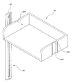
도 4는 본 발명인 시스템 가구 구조에 있어서 포스트프레임의 체결브라켓에 수납함을 결합하기 위한 분리 사시도,
도 5는 본 발명인 시스템 가구 구조에 있어서 포스트프레임에 수납함이 결합된 일실시예의 사시도,
도 6은 본 발명인 시스템 가구 구조에 있어서 포스트프레임에 수납함이 결합된 다른실시예의 사시도,
도 7은 본 발명인 시스템 가구 구조에 있어서 포스트프레임에 수납함이 결합된 또 다른실시예의 사시도,
도 8은 본 발명인 시스템 가구 구조에 있어서 포스트프레임에 수납함이 결합된 상태에서 커버패널을 분리한 상태의 또 다른실시예의 분리 사시도,
도 9는 본 발명인 시스템 가구 구조에 있어서 도 8의 결합 사시도,
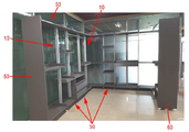
도 10은 본 발명인 시스템 가구 구조에 있어서 포스트프레임에 수납함 및 커버패널이 결합된 또 다른실시예의 사시도,
도 11은 본 발명인 시스템 가구 구조에 있어서 포스트프레임에 수납함이 결합된 또 다른실시예의 사시도,
도 12는 본 발명인 시스템 가구 구조에 있어서 포스트프레임에 수납함 및 커버패널이 결합된 또 다른실시예의 사시도,
도 13은 본 발명인 시스템 가구 구조에 있어서 포스트프레임에 수납함 또는 책상이 결합된 또 다른실시예의 사시도,
도 14는 본 발명인 시스템 가구 구조에 있어서 포스트프레임에 수납함 및 커버패널이 결합된 또 다른실시예의 사시도이다.1 is a perspective view of a post frame in the system furniture structure of the present invention;
2 is an exploded perspective view of FIG. 1 in the system furniture structure of the present invention;
Figure 3 is a perspective view of the main part of the fastening bracket and the post frame sliding up and down through the guide passage in the system furniture structure of the present invention,
Figure 4 is an exploded perspective view for coupling the storage box to the fastening bracket of the post frame in the system furniture structure of the present inventors,
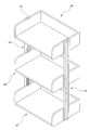
5 is a perspective view of an embodiment in which the storage box is coupled to a post frame in the system furniture structure of the present invention;
6 is a perspective view of another embodiment in which the storage box is coupled to the post frame in the system furniture structure of the present invention;
7 is a perspective view of another embodiment in which the storage box is coupled to the post frame in the system furniture structure of the present invention;
8 is an exploded perspective view of yet another embodiment of a state in which the cover panel is removed in a state in which a holder is coupled to a post frame in the system furniture structure of the present invention;
9 is a perspective view of the combination of Fig. 8 in the system furniture structure of the present invention;
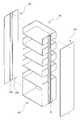
10 is a perspective view of another embodiment in which the storage box and the cover panel are coupled to a post frame in the system furniture structure of the present invention;
11 is a perspective view of another embodiment in which the storage box is coupled to a post frame in the system furniture structure of the present invention;
12 is a perspective view of another embodiment in which the storage box and the cover panel are coupled to a post frame in the system furniture structure of the present invention;
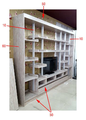
13 is a perspective view of another embodiment in which the storage box or desk is coupled to a post frame in the system furniture structure of the present invention;
14 is a perspective view of another embodiment in which the storage box and the cover panel are coupled to a post frame in the system furniture structure of the present invention.
본 명세서에 개시되어 있는 본 발명의 개념에 따른 실시 예들에 대해서 특정한 구조적 또는 기능적 설명들은 단지 본 발명의 개념에 따른 실시 예들을 설명하기 위한 목적으로 예시된 것으로서, 본 발명의 개념에 따른 실시 예들은 다양한 변경들을 가할 수 있고 여러 가지 형태들을 가질 수 있으므로 본 발명의 사상 및 기술 범위에 포함되는 모든 변경, 균등물, 또는 대체물을 포함하며, 명세서 및 청구범위에 사용되는 용어나 단어는 통상적이거나 사전적인 의미로 한정 해석되지 않음은 물론, 발명자는 그 자신의 발명을 가장 최선의 방법으로 설명하기 위해 용어의 개념을 적절하게 정의할 수 있다는 점에 입각하여, 본 발명의 기술적 사상에 부합하는 의미와 개념으로 해석되어야 한다. 따라서, 본 발명의 명세서에 기재된 실시예와 도면에 도시된 구성은 본 발명의 가장 바람직한 일 실시예에 불과할 뿐이고 본 발명의 기술적 사상을 모두 대변하는 것은 아닌바, 본 발명의 출원 시점에 있어서 이를 대체할 수 있는 다양한 균등물과 변형예들이 가능하거나 존재할 수 있음을 이해하여야 할 것이다.Specific structural or functional descriptions of the embodiments according to the inventive concept disclosed herein are provided for the purpose of describing the embodiments according to the inventive concept only. As various changes may be made and various forms may be included, all modifications, equivalents, or substitutes included in the spirit and technical scope of the present invention are included, and the terms or words used in the specification and the claims are ordinary or dictionary. Not limited to the meaning, of course, the inventor can properly define the concept of the term in order to explain his invention in the best way, meaning and concept consistent with the technical spirit of the present invention Should be interpreted as Therefore, the configuration shown in the embodiments and drawings described in the specification of the present invention is only the most preferred embodiment of the present invention and does not represent all of the technical idea of the present invention, it is replaced at the time of filing the present invention It will be appreciated that various equivalents and variations are possible or possible.
또한, 본 발명의 명세서에서 다르게 정의되지 않는 한, 기술적이거나 과학적인 용어를 포함해서 여기서 사용되는 모든 용어들은 본 발명이 속하는 기술 분야에서 통상의 지식을 가진 자에 의해 일반적으로 이해되는 것과 동일한 의미를 가진다. 일반적으로 사용되는 사전에 정의되어 있는 것과 같은 용어들은 관련 기술의 문맥상 가지는 의미와 일치하는 의미를 갖는 것으로 해석되어야 하며, 본 명세서에서 명백하게 정의하지 않는 한, 이상적이거나 과도하게 형식적인 의미로 해석되지 않는다. Also, unless otherwise defined in the specification of the present invention, all terms used herein, including technical or scientific terms, have the same meaning as commonly understood by one of ordinary skill in the art to which the present invention belongs. Have Terms such as those defined in the commonly used dictionaries should be construed as having meanings consistent with the meanings in the context of the related art, and are not construed in ideal or excessively formal meanings unless expressly defined herein. Do not.
이하 본 발명의 바람직한 실시 형태를 첨부하는 도면을 참조하여 상세히 설명한다.Hereinafter, with reference to the accompanying drawings, preferred embodiments of the present invention will be described in detail.
도 1은 본 발명인 시스템 가구 구조에 있어서 포스트프레임의 사시도이며, 도 2는 본 발명인 시스템 가구 구조에 있어서 도 1의 분리 사시도이고, 도 3은 본 발명인 시스템 가구 구조에 있어서 가이드통로를 통해 상하로 슬라이딩되는 체결브라켓 및 포스트프레임의 요부 사시도이며, 도 4는 본 발명인 시스템 가구 구조에 있어서 포스트프레임의 체결브라켓에 수납함을 결합하기 위한 분리 사시도이고, 도 5는 본 발명인 시스템 가구 구조에 있어서 포스트프레임에 수납함이 결합된 일실시예의 사시도이며, 도 6은 본 발명인 시스템 가구 구조에 있어서 포스트프레임에 수납함이 결합된 다른실시예의 사시도이고, 도 7은 본 발명인 시스템 가구 구조에 있어서 포스트프레임에 수납함이 결합된 또 다른실시예의 사시도이며, 도 8은 본 발명인 시스템 가구 구조에 있어서 포스트프레임에 수납함이 결합된 상태에서 커버패널을 분리한 상태의 또 다른실시예의 분리 사시도이고, 도 9는 본 발명인 시스템 가구 구조에 있어서 도 8의 결합 사시도이며, 도 10은 본 발명인 시스템 가구 구조에 있어서 포스트프레임에 수납함 및 커버패널이 결합된 또 다른실시예의 사시도이고, 도 11은 본 발명인 시스템 가구 구조에 있어서 포스트프레임에 수납함이 결합된 또 다른실시예의 사시도이며, 도 12는 본 발명인 시스템 가구 구조에 있어서 포스트프레임에 수납함 및 커버패널이 결합된 또 다른실시예의 사시도이고, 도 13은 본 발명인 시스템 가구 구조에 있어서 포스트프레임에 수납함 또는 책상이 결합된 또 다른실시예의 사시도이며, 도 14는 본 발명인 시스템 가구 구조에 있어서 포스트프레임에 수납함 및 커버패널이 결합된 또 다른실시예의 사시도이다.Figure 1 is a perspective view of the post frame in the system furniture structure of the present invention, Figure 2 is an exploded perspective view of Figure 1 in the system furniture structure of the present invention, Figure 3 is sliding up and down through the guide passage in the system furniture structure of the present invention. Figure 4 is a perspective view of the main part of the fastening bracket and the post frame to be separated, Figure 4 is a separate perspective view for coupling the storage box to the fastening bracket of the post frame in the system furniture structure of the present invention, Figure 5 is a storage box in the post frame in the system furniture structure of the present invention Figure 6 is a perspective view of one embodiment combined, Figure 6 is a perspective view of another embodiment in which the storage box is coupled to the post frame in the system furniture structure of the present invention, Figure 7 is a combination of the storage box and the post frame in the system furniture structure of the present invention 8 is a perspective view of another embodiment, Figure 8 is a system furniture structure of the present inventors Fig. 9 is an exploded perspective view of still another embodiment of the cover panel in a state in which the storage box is coupled to a post frame, and Fig. 9 is a perspective view of Fig. 8 in the system furniture structure of the present invention, and Fig. 10 is a system furniture of the present invention. 12 is a perspective view of another embodiment in which the storage box and the cover panel are coupled to the post frame in structure, and FIG. 11 is a perspective view of another embodiment in which the storage box is coupled to the post frame in the system furniture structure of the present invention, and FIG. 13 is a perspective view of another embodiment in which a storage box and a cover panel are coupled to a post frame in a furniture structure, and FIG. 13 is a perspective view of another embodiment in which a storage box or a desk is coupled to a post frame in a system furniture structure of the present invention, and FIG. In the system furniture structure of the present invention, a storage box and a cover panel are coupled to a post frame. Is a perspective view of yet another embodiment.
지시부호 10은 포스트프레임을 지시하는 것으로서 상기 포스트프레임(10)은 도 2에 도시된 바와 같이 중앙에는 전후로 구획된 판상의 구획벽(100)이 구비되며 상기 구획벽(100)의 양측에는 관통공(110)이 천공되어 있는 일방향으로 길게 형상된 일체형의 바 형태로서 상기 구획벽(100) 전후 양측에는 연장편(120)이 각각 일체로 형성되어 있고 상기 연장편(120)의 내측에는 가이드통로(130)가 구비되며 외측 끝단에는 단턱(140)이 형성되어 있는 일체형으로 이루어진 구조이며,
지시부호 20은 체결브라켓을 지시하는 것으로서, 상기 체결브라켓(20)은 도 2 및 도 3에 도시된 바와 같이 상기 가이드통로(130)에 착탈 가능하도록 결합되어 상하로 승강 가능하도록 되어 있는 것으로서 일측면 양끝단이 절개되어 하방향으로 길게 걸림턱(200)이 구비되어 있고 상기 걸림턱(200)이 형성된 양끝단이 절개된 상면에는 일측으로 연장 형성된 체결판(210)이 형성되어 있으며 일측면 중앙에는 나사홈(220)이 구비된 복수개 이상으로 이루어진 것이다.
특히, 도면상에서는 도시되지 아니하였으나 상기 포스트프레임(10)의 전후 양면에 각각 가이드통로(130)가 구비되어 있는 구조로서 상기 체결브라켓(20) 또한 상기 포스트프레임(10)의 전후 양면에 구비된 가이드통로(130)에 착탈 가능하게 체결되어 상하로 슬라이딩되어 최적의 위치 또는 사용자가 원하는 위치에 고정 결합 가능하도록 하는 것이다.In particular, although not shown in the drawings, the
다음, 지시부호 30은 서포트브라켓을 지시하는 것으로서 도 3에 도시된 바와 같이 상기 서포트브라켓(30)은 상기 포스트프레임(10)의 하단 상기 가이드통로(130)에는 상기 체결브라켓(20)이 체결된 상태에서 상기 연장편(120)의 외측에 형성된 단턱(140) 내측으로 결합 가능하도록 일측에는 수직상의 결합판(300)이 형성되고 상기 결합판(300) 중앙에는 결합공(301)이 천공되어 있고 타측에는 수평상의 받침판(310)이 구비되며 상기 받침판(310) 중앙에는 나사공(311)이 일체로 형성된 것이다.Next, the
상기 서포트브라켓(30)은 도 5에 도시된 바와 같이 최하단에 구비되는 하기에서 설명하는 수납함(50)을 지지하고 결합 고정키 위한 역할을 수행하는 것이다.The
지시부호 40은 마감브라켓을 지시하는 것으로서 상기 마감브라켓(400은 도 2에 도시된 바와 같이 상기 포스트프레임(10) 양끝단에는 일면은 평상으로 이루어지고 타면 양측에는 상기 관통공(110)에 삽입 마감 가능하도록 마개구(400)가 일체로 형성된 것이다.
다음, 지시부호 50은 서랍 형태 또는 선반 형태의 수납함을 지시하는 것으로서 도 5 내지 도 14에 도시된 바와 같이 그 형상은 다양성을 갖고 있으나 기본적인 구조는 상기 체결브라켓(20)에 체결 가능하도록 양측 중앙에 길이방향으로 길게 홈부(500)가 형성되어 있고 상기 홈부(500) 상측 중앙에는 상기 체결브라켓(20)의 나사홈(220)과 일치하는 제1 체결공(501)이 천공되어 있는 대표적으로 서랍 형태로 이루어지되 본 발명의 도면에서는 예시에 불과하고 상기 구조를 갖는 다양한 형상을 표출 가능하도록 한 것이다.Next, the
지시부호 60은 커버패널을 지시하는 것으로서, 상기 커버패널(60)은 도 8 내지 도 10에 도시되어 있고 또한 도 12 및 도 14에 그 실시예가 도시된 바와 같이 상기 포스트프레임(10) 외측 길이방향으로 길게 체결 구비 가능하도록 일측면 중앙에 길이방향으로 길게 삽입홈(600)을 형성하고 상기 삽입홈(600) 상측 중앙에는 상기 체결브라켓(20)의 나사홈(220)과 일치하는 제2 체결공(601)이 천공되어 있는 판상의 구조를 갖는 것이다.
바람직하게는 도 10 및 도 11에 도시된 바와 같이 상기 수납함(50) 전면에 도어(70)를 추가 가능하도록 한 것이다.Preferably, as shown in FIGS. 10 and 11, the
이하, 본 발명의 작용에 대하여 설명하면 다음과 같다.Hereinafter, the operation of the present invention will be described.
우선, 포스트프레임(10)에 체결브라켓(20), 서포트브라켓(30)을 체결하여야 하며 이에 대한 구체적으로 설명하면, 도 2에 도시된 바와 같이 상기 체결브라켓(20)의 일면을 상기 구획벽(100)에 밀착시켜 상기 가이드통로(130)으로 슬라이딩 결합하되 상기 체결브라켓(20)의 걸림턱(200)이 상기 포스트프레임(10)의 연장편(120)의 이면에 체결토록 함으로서 도 3에 도시된 바와 같이 상기 체결브라켓(20)은 포스트프레임(10)으로 부터 이탈되지 아니하면서 상기 가이드통로(130)를 따라 상하로 슬라이딩 가능하도록 체결되는 것이다.First, the
상기 체결브라켓(20)의 체결은 구획벽(100)을 기준으로 전후에 필요에 따라 체결 가능한 것이며 도 4는 일측에만 체결한 에시에 불과한 것으로서 상기와 같이 체결브라켓(20)을 가이드통로(130)에 체결한 연후에 나사홈(220)과 수납함(50)의 제1 체결공(501)을 일치시킨 후 볼트등으로 체결하면 상기 수납함(50)의 홈부(500)에 포스트프레임(10)의 관통공(110) 외주면에 밀착되면서 소정의 위치에 수납함(50)이 고정 결합되되 도 4는 일측 즉, 하나의 포스트프레임(10)에 체결하는 과정을 분리 사시도로 표현한 것으로서 타측 또한 수평을 맞춰서 동일한 방법으로 체결하면 상기 체결브라켓(20)의 체결판(210)이 상기 수납함(50)의 홈부(500) 상면에 긴밀하게 밀착되어 고정 결합되는 것이다.The fastening of the
이와 같이 체결브라켓(20)을 복수개 이상 상기 가이드통로(130)에 결합하여 도 5 내지 도 7에 도시된 바와 같이 다양한 형상 및 구조를 표출 가능하도록 하는 것이며, 구체적으로 설명하면 상기와 같이 복수개이상의 체결브라켓(20)을 상기와 같은 체결방식으로 체결한 다음 마감 즉, 완성을 하기 위해서는 도 2에 도시된 바와 같이 포스트프레임(10)의 하측에서 상측방향으로 가이드통로(10)에 상기 체결브라켓(20)을 체결한 다음 그 외측으로 상기 서포트브라켓(30)을 상기 연장편(120)의 외측 단턱(140) 사이로 상기 서포트브라켓(30)의 결합판(300)을 체결한 후 상기 서포트브라켓(30)의 결합판(300)에 구비된 결합공(301)과 상기 체결브라켓(20)의 나사홈(220) 및 상기 수납함(50)의 제1 체결공(501)을 일치시킨 후 볼트등으로 고정 한 다음, 상기 받침판(310)에 구비된 나사공(311)과 수납함(50)의 측벽을 볼트 등으로 고정하여 상기 받침판(310)과 수납함(50)을 측면 및 바닥면에 2중으로 고정 결합하는 것이다.As described above, a plurality of
다음, 최종 마감은 상기 마감브라켓(40)을 상기 포스트프레임(10)의 상하면에 구비된 관통공(110)에 마개구(400)를 일치하여 상기 마감브라켓(40)을 결합하여 마감토록 함으로서 본 발명이 완성되는 것이며, 해체시에는 역순으로 해체한 다음 다양한 형상의 구조를 구현 및 표출 가능한 것이다.Next, the final finish is seen by combining the
더움 바람직하게는 커버패널(60)을 도 8에 도시된 바와 같이 상기 포스트프레임(10)의 이면에 구비된 가이드통로(130) 상하단에 체결브라켓(20)을 결합 한 후 체결브라켓(20)의 나사홈(220)과 커버패널(60) 상하면 중앙 즉, 삽입홈(600)에 천공된 제2 체결공(601)을 일치 시킨 후 볼트등으로 상기 커버패널(60)을 상기 포스트프레임(10)에 결합하면 상기 삽입홈(600) 내측으로 상기 포스트프레임(10)의 관통공(110) 외측에 긴밀하게 밀착 결합되어 고정됨으로서 도 9 및 도 10에 도시된 바와 같이 시스템 가구가 완성되는 것으로서 상기 커버패널(60)의 삽입홈(600)에 포스트프레임(10)이 밀착 결합시에도 상기 체결브라켓(20)의 체결판(210)이 상기 삽입홈(600) 상면에 긴밀하게 밀착 체결되어 견고성을 더욱 발휘토록 하는 것이다.More preferably, as shown in FIG. 8, the
더욱 바람직하게는, 도 10 및 도 11에 도시된 바와 같이 상기 수납함(50) 전면에 도어(70)을 힌지를 이용하여 결합하여 외부에서 볼때 미관상 미려하고 고급스럽게 연출 가능하도록 한 것이다.More preferably, as shown in FIGS. 10 and 11, the
상기와 같이 결합함으로서 도 11 내지 도 14와 같이 다양한 형상의 시스템 가구를 구현할 수 있으며 본 발명에서 도시된 예시 이상으로 더욱 다양한 형상 및 구조의 시스템 가구를 구현할 수 있는 것이다. By combining as described above it is possible to implement a system furniture of various shapes as shown in Figures 11 to 14 and to implement a system furniture of more various shapes and structures than the example shown in the present invention.
상기와 같이 구성된 본 발명은 포스트프레임의 다양한 길이 적용이 가능하도록 하여 포스트프레임이 천정과 바닥면에 양단이 각각 접하며 고정되는 기존의 조립 형태에서 탈피 다양성을 추구할 수 있으며, 특히 상기 포스트프레임 길이방향 양측에 가이드통로를 통해 상하로 슬라이딩되는 체결브라켓을 구비하여 사용자가 자신의 취향에 맞도록 수납함의 배치를 다양하게 변형 가능하도록 함으로서 실내 인테리어의 변화로 분위기 연출의 다양성을 추구 및 견고성과 공간 활용성 및 실내 인테리어 효과를 극대화 시킬 수 있는 것이다.The present invention configured as described above can be applied to various lengths of the post frame to pursue a variety of stripping in the existing assembly form in which the post frame is fixed to contact with both ends on the ceiling and the bottom surface, in particular in the post frame longitudinal direction By providing fastening brackets that slide up and down through guide passages on both sides, the user can variously change the arrangement of the storage box to suit his or her taste. And to maximize the interior effect.
이상과 같이 본 발명은 비록 한정된 실시예와 도면에 의해 설명되었으나, 본 발명은 상기 실시예에 한정되지 않음은 물론이며, 본 발명이 속하는 분야에서 통상의 기술적 지식을 가진 자에 의해 상기 기재된 내용으로부터 다양한 수정 및 변형이 가능할 수 있음은 물론이다.As described above, although the present invention has been described by way of limited embodiments and drawings, the present invention is, of course, not limited to the above embodiments, and the present invention has been described by those skilled in the art to which the present invention pertains. Of course, various modifications and variations may be possible.
따라서 본 발명에서의 기술적 사상은 아래에 기재되는 청구범위에 의해 파악되어야 하되 이의 균등 또는 등가적 변형 모두 본 발명의 기술적 사상의 범주에 속함은 자명하다 할 것이다.Therefore, the technical idea in the present invention should be understood by the claims described below, but it will be apparent that all equivalent or equivalent modifications belong to the scope of the technical idea of the present invention.
10 : 포스트프레임 20 : 체결브라켓
30 : 서포트브라켓 40 : 마감브라켓
50 : 수납함 60 : 커버패널
70 : 도어 100 : 구획벽
110 : 관통공 120 : 연장편
130 : 가이드통로 140 : 단턱
200 : 걸림턱 210 : 체결판
220 : 나사홈 300 : 결합판
301 : 결합공 310 : 받침판
311 : 나사공 400 : 마개구
500 : 홈부 501 : 제1 체결공
600 : 삽입홈 601 : 제2 체결공10: post frame 20: fastening bracket
30: support bracket 40: finishing bracket
50: storage box 60: cover panel
70: door 100: partition wall
110: through hole 120: extension piece
130: guide passage 140: step
200: engaging jaw 210: fastening plate
220: screw groove 300: bonding plate
301: bonding hole 310: support plate
311: screw hole 400: stopper
500: groove 501: first fastening hole
600: insertion groove 601: second fastening hole
Claims (4)
상기 가이드통로(130)에 착탈 가능하도록 결합되어 상하로 승강 가능하도록 되어 있는 것으로서 일측면 양끝단이 절개되어 하방향으로 길게 걸림턱(200)이 구비되어 있고 상기 걸림턱(200)이 형성된 양끝단이 절개된 상면에는 일측으로 연장 형성된 체결판(210)이 형성되어 있으며 일측면 중앙에는 나사홈(220)이 구비된 복수개 이상의 체결브라켓(20)과,
상기 포스트프레임(10)의 하단 상기 가이드통로(130)에는 상기 체결브라켓(20)이 체결된 상태에서 상기 연장편(120)의 외측에 형성된 단턱(140) 내측으로 결합 가능하도록 일측에는 수직상의 결합판(300)이 형성되고 상기 결합판(300) 중앙에는 결합공(301)이 천공되어 있고 타측에는 수평상의 받침판(310)이 구비되며 상기 받침판(310) 중앙에는 나사공(311)이 일체로 형성된 서포트브라켓(30)과,
상기 포스트프레임(10) 양끝단에는 일면은 평상으로 이루어지고 타면 양측에는 상기 관통공(110)에 삽입 마감 가능하도록 마개구(400)가 일체로 형성된 마감브라켓(40)으로 이루어진 것을 특징으로 하는 시스템 가구 구조.A plate-shaped partition wall 100 partitioned back and forth is provided at the center, and both sides of the partition wall 100 are formed as an integral bar shape long in one direction in which the through-hole 110 is perforated. The extension piece 120 is integrally formed on both sides, and the guide passage 130 is provided on the inner side of the extension piece 120, and an integral post frame 10 having an end step 140 formed on the outer end thereof. ,
It is coupled to the guide passage 130 to be detachable and is capable of lifting up and down as one end is cut on both sides and is provided with a locking jaw (200) long in the downward direction and both ends formed with the locking jaw (200) The cut-out upper surface is formed with a fastening plate 210 extending to one side and a plurality of fastening brackets 20 having a screw groove 220 in the center of one side,
Vertically coupled to one side to be coupled to the guide passage 130 at the lower end of the post frame 10 to the inside of the step 140 formed on the outside of the extension piece 120 in the state in which the fastening bracket 20 is fastened. The plate 300 is formed and the coupling plate 301 is perforated in the center of the coupling plate 300, the other side is provided with a horizontal support plate 310 and the screw hole 311 in the center of the support plate 310 integrally Formed support bracket (30),
One end is formed on both ends of the post frame 10 at both ends, and the other side is formed with a closing bracket 40 integrally formed with a stopper 400 so as to be inserted into the through hole 110. Furniture structure.
상기 체결브라켓(20)에 체결 가능하도록 양측 중앙에 길이방향으로 길게 홈부(500)가 형성되어 있고 상기 홈부(500) 상측 중앙에는 상기 체결브라켓(20)의 나사홈(220)과 일치하는 제1 체결공(501)이 천공되어 있는 서랍 형태의 수납함(50)이 추가된 것을 특징으로 하는 시스템 가구 구조.
The method of claim 1,
Grooves 500 are formed in both longitudinal centers in the longitudinal direction to be fastened to the fastening brackets 20, and a first groove coincides with the screw grooves 220 of the fastening brackets 20 in the upper centers of the grooves 500. System furniture structure, characterized in that the addition of a drawer-type holder box 50 is fastened to the fastening hole (501).
상기 포스트프레임(10) 외측 길이방향으로 길게 체결 구비 가능하도록 일측면 중앙에 길이방향으로 길게 삽입홈(600)을 형성하고 상기 삽입홈(600) 상측 중앙에는 상기 체결브라켓(20)의 나사홈(220)과 일치하는 제2 체결공(601)이 천공되어 있는 커버패널(60)이 추가된 것을 특징으로 하는 시스템 가구 구조.
The method of claim 1,
The insertion groove 600 is formed long in the longitudinal direction at the center of one side to enable the fastening in the longitudinal direction of the outer side of the post frame 10, and the screw groove of the fastening bracket 20 at the center of the upper side of the insertion groove 600 ( System furniture structure, characterized in that the cover panel 60 is added with a second fastening hole (601) coinciding with the 220.
상기 수납함(50) 전면에 도어(70)를 추가 가능하도록 한 것을 특징으로 하는 시스템 가구 구조.
The method of claim 2,
System furniture structure, characterized in that the door 70 is added to the front of the holder (50).
Priority Applications (1)
| Application Number | Priority Date | Filing Date | Title |
|---|---|---|---|
| KR1020180052954A KR102092626B1 (en) | 2018-05-09 | 2018-05-09 | System furniture structure |
Applications Claiming Priority (1)
| Application Number | Priority Date | Filing Date | Title |
|---|---|---|---|
| KR1020180052954A KR102092626B1 (en) | 2018-05-09 | 2018-05-09 | System furniture structure |
Publications (2)
| Publication Number | Publication Date |
|---|---|
| KR20190128807A true KR20190128807A (en) | 2019-11-19 |
| KR102092626B1 KR102092626B1 (en) | 2020-03-24 |
Family
ID=68771108
Family Applications (1)
| Application Number | Title | Priority Date | Filing Date |
|---|---|---|---|
| KR1020180052954A KR102092626B1 (en) | 2018-05-09 | 2018-05-09 | System furniture structure |
Country Status (1)
| Country | Link |
|---|---|
| KR (1) | KR102092626B1 (en) |
Cited By (2)
| Publication number | Priority date | Publication date | Assignee | Title |
|---|---|---|---|---|
| KR200493971Y1 (en) * | 2020-11-02 | 2021-07-08 | 라온시스템가구(주) | Double endcap for divided-shelf of open type-system furniture |
| KR102434446B1 (en) * | 2021-09-17 | 2022-08-19 | 주식회사 주방뱅크 | Showcase for fresh food |
Citations (7)
| Publication number | Priority date | Publication date | Assignee | Title |
|---|---|---|---|---|
| KR20010035261A (en) * | 2001-01-30 | 2001-05-07 | 안재순 | A prefabricated chest and operating method thereof |
| KR100461779B1 (en) | 2001-06-11 | 2004-12-14 | 엔이씨 일렉트로닉스 가부시키가이샤 | Method of manufacturing semiconductor devices and semiconductor manufacturing apparatus |
| KR100461778B1 (en) | 2003-12-20 | 2004-12-16 | 이복섭 | A floor mat for advertisement |
| KR20090006712U (en) * | 2007-12-28 | 2009-07-02 | 주식회사 퍼맥스 | Srructure of bed frame |
| KR20100018149A (en) * | 2008-08-06 | 2010-02-17 | (주)디폴 | A sectional shelf |
| KR101375599B1 (en) * | 2013-03-08 | 2014-03-17 | 주식회사 동성사 | Stand-alone type furniture for dress room system |
| KR101379685B1 (en) * | 2013-12-19 | 2014-04-01 | 영남강철 주식회사 | Multipurpose shelf |
-
2018
- 2018-05-09 KR KR1020180052954A patent/KR102092626B1/en active IP Right Grant
Patent Citations (7)
| Publication number | Priority date | Publication date | Assignee | Title |
|---|---|---|---|---|
| KR20010035261A (en) * | 2001-01-30 | 2001-05-07 | 안재순 | A prefabricated chest and operating method thereof |
| KR100461779B1 (en) | 2001-06-11 | 2004-12-14 | 엔이씨 일렉트로닉스 가부시키가이샤 | Method of manufacturing semiconductor devices and semiconductor manufacturing apparatus |
| KR100461778B1 (en) | 2003-12-20 | 2004-12-16 | 이복섭 | A floor mat for advertisement |
| KR20090006712U (en) * | 2007-12-28 | 2009-07-02 | 주식회사 퍼맥스 | Srructure of bed frame |
| KR20100018149A (en) * | 2008-08-06 | 2010-02-17 | (주)디폴 | A sectional shelf |
| KR101375599B1 (en) * | 2013-03-08 | 2014-03-17 | 주식회사 동성사 | Stand-alone type furniture for dress room system |
| KR101379685B1 (en) * | 2013-12-19 | 2014-04-01 | 영남강철 주식회사 | Multipurpose shelf |
Cited By (2)
| Publication number | Priority date | Publication date | Assignee | Title |
|---|---|---|---|---|
| KR200493971Y1 (en) * | 2020-11-02 | 2021-07-08 | 라온시스템가구(주) | Double endcap for divided-shelf of open type-system furniture |
| KR102434446B1 (en) * | 2021-09-17 | 2022-08-19 | 주식회사 주방뱅크 | Showcase for fresh food |
Also Published As
| Publication number | Publication date |
|---|---|
| KR102092626B1 (en) | 2020-03-24 |
Similar Documents
| Publication | Publication Date | Title |
|---|---|---|
| RU2763642C2 (en) | Box for wall-mounted storage system | |
| US20110115351A1 (en) | Modular Case Goods and Components | |
| US20050099101A1 (en) | Vanity cabinet with drawers | |
| KR102092626B1 (en) | System furniture structure | |
| US4371221A (en) | Composite modular element structure for furnishings | |
| US20090153006A1 (en) | No-tools interchangeable drawer front system | |
| US20120256527A1 (en) | Piece of furniture having at least one sliding door | |
| KR200451053Y1 (en) | A bookcase of variable type | |
| CN204132834U (en) | A kind of Multifunctional assembled cabinet | |
| KR200211411Y1 (en) | Fabricated acceptance and sectional bookcase | |
| KR200236345Y1 (en) | Prefabricated furniture having various uses | |
| KR102513043B1 (en) | Assembly Type System Furniture Frame | |
| JPH0249083B2 (en) | ||
| KR100241720B1 (en) | System furniture | |
| CN210276484U (en) | Multifunctional combined furniture | |
| JP3094417U (en) | Renewal cabinet unit and system kitchen | |
| JPS6228237Y2 (en) | ||
| CN210329870U (en) | Bookshelf unit and combined bookcase | |
| KR200352622Y1 (en) | Display rack for a dress room | |
| JPS62545Y2 (en) | ||
| KR200461975Y1 (en) | Furniture comprising sliding storage case | |
| KR200369562Y1 (en) | Structure of Supporting a Panel of Structure installed on the Surface of a Wall | |
| CN206354736U (en) | Clothes rail component and corner wardrobe | |
| CN112167847A (en) | Multi-opening-mode household wall cabinet | |
| JPS6129356Y2 (en) |
Legal Events
| Date | Code | Title | Description |
|---|---|---|---|
| A201 | Request for examination | ||
| E902 | Notification of reason for refusal | ||
| E701 | Decision to grant or registration of patent right | ||
| GRNT | Written decision to grant |