KR20190113988A - Controller for Surgical Instruments - Google Patents
Controller for Surgical Instruments Download PDFInfo
- Publication number
- KR20190113988A KR20190113988A KR1020197027618A KR20197027618A KR20190113988A KR 20190113988 A KR20190113988 A KR 20190113988A KR 1020197027618 A KR1020197027618 A KR 1020197027618A KR 20197027618 A KR20197027618 A KR 20197027618A KR 20190113988 A KR20190113988 A KR 20190113988A
- Authority
- KR
- South Korea
- Prior art keywords
- controller
- user
- movement
- shaft
- relative
- Prior art date
Links
Images


Classifications
-
- A—HUMAN NECESSITIES
- A61—MEDICAL OR VETERINARY SCIENCE; HYGIENE
- A61B—DIAGNOSIS; SURGERY; IDENTIFICATION
- A61B1/00—Instruments for performing medical examinations of the interior of cavities or tubes of the body by visual or photographical inspection, e.g. endoscopes; Illuminating arrangements therefor
- A61B1/00002—Operational features of endoscopes
- A61B1/00039—Operational features of endoscopes provided with input arrangements for the user
- A61B1/00042—Operational features of endoscopes provided with input arrangements for the user for mechanical operation
-
- A—HUMAN NECESSITIES
- A61—MEDICAL OR VETERINARY SCIENCE; HYGIENE
- A61B—DIAGNOSIS; SURGERY; IDENTIFICATION
- A61B1/00—Instruments for performing medical examinations of the interior of cavities or tubes of the body by visual or photographical inspection, e.g. endoscopes; Illuminating arrangements therefor
- A61B1/00002—Operational features of endoscopes
- A61B1/00039—Operational features of endoscopes provided with input arrangements for the user
-
- A—HUMAN NECESSITIES
- A61—MEDICAL OR VETERINARY SCIENCE; HYGIENE
- A61B—DIAGNOSIS; SURGERY; IDENTIFICATION
- A61B1/00—Instruments for performing medical examinations of the interior of cavities or tubes of the body by visual or photographical inspection, e.g. endoscopes; Illuminating arrangements therefor
- A61B1/00147—Holding or positioning arrangements
- A61B1/00149—Holding or positioning arrangements using articulated arms
-
- A—HUMAN NECESSITIES
- A61—MEDICAL OR VETERINARY SCIENCE; HYGIENE
- A61B—DIAGNOSIS; SURGERY; IDENTIFICATION
- A61B1/00—Instruments for performing medical examinations of the interior of cavities or tubes of the body by visual or photographical inspection, e.g. endoscopes; Illuminating arrangements therefor
- A61B1/313—Instruments for performing medical examinations of the interior of cavities or tubes of the body by visual or photographical inspection, e.g. endoscopes; Illuminating arrangements therefor for introducing through surgical openings, e.g. laparoscopes
- A61B1/3132—Instruments for performing medical examinations of the interior of cavities or tubes of the body by visual or photographical inspection, e.g. endoscopes; Illuminating arrangements therefor for introducing through surgical openings, e.g. laparoscopes for laparoscopy
-
- A—HUMAN NECESSITIES
- A61—MEDICAL OR VETERINARY SCIENCE; HYGIENE
- A61B—DIAGNOSIS; SURGERY; IDENTIFICATION
- A61B17/00—Surgical instruments, devices or methods, e.g. tourniquets
- A61B17/00234—Surgical instruments, devices or methods, e.g. tourniquets for minimally invasive surgery
-
- A—HUMAN NECESSITIES
- A61—MEDICAL OR VETERINARY SCIENCE; HYGIENE
- A61B—DIAGNOSIS; SURGERY; IDENTIFICATION
- A61B17/00—Surgical instruments, devices or methods, e.g. tourniquets
- A61B17/28—Surgical forceps
- A61B17/29—Forceps for use in minimally invasive surgery
-
- A—HUMAN NECESSITIES
- A61—MEDICAL OR VETERINARY SCIENCE; HYGIENE
- A61B—DIAGNOSIS; SURGERY; IDENTIFICATION
- A61B34/00—Computer-aided surgery; Manipulators or robots specially adapted for use in surgery
- A61B34/25—User interfaces for surgical systems
-
- A—HUMAN NECESSITIES
- A61—MEDICAL OR VETERINARY SCIENCE; HYGIENE
- A61B—DIAGNOSIS; SURGERY; IDENTIFICATION
- A61B34/00—Computer-aided surgery; Manipulators or robots specially adapted for use in surgery
- A61B34/30—Surgical robots
-
- A—HUMAN NECESSITIES
- A61—MEDICAL OR VETERINARY SCIENCE; HYGIENE
- A61B—DIAGNOSIS; SURGERY; IDENTIFICATION
- A61B34/00—Computer-aided surgery; Manipulators or robots specially adapted for use in surgery
- A61B34/30—Surgical robots
- A61B34/35—Surgical robots for telesurgery
-
- A—HUMAN NECESSITIES
- A61—MEDICAL OR VETERINARY SCIENCE; HYGIENE
- A61B—DIAGNOSIS; SURGERY; IDENTIFICATION
- A61B34/00—Computer-aided surgery; Manipulators or robots specially adapted for use in surgery
- A61B34/70—Manipulators specially adapted for use in surgery
- A61B34/74—Manipulators with manual electric input means
-
- A—HUMAN NECESSITIES
- A61—MEDICAL OR VETERINARY SCIENCE; HYGIENE
- A61B—DIAGNOSIS; SURGERY; IDENTIFICATION
- A61B90/00—Instruments, implements or accessories specially adapted for surgery or diagnosis and not covered by any of the groups A61B1/00 - A61B50/00, e.g. for luxation treatment or for protecting wound edges
- A61B90/50—Supports for surgical instruments, e.g. articulated arms
- A61B90/53—Supports for surgical instruments, e.g. articulated arms connected to the surgeon's body, e.g. by a belt
-
- A—HUMAN NECESSITIES
- A61—MEDICAL OR VETERINARY SCIENCE; HYGIENE
- A61B—DIAGNOSIS; SURGERY; IDENTIFICATION
- A61B90/00—Instruments, implements or accessories specially adapted for surgery or diagnosis and not covered by any of the groups A61B1/00 - A61B50/00, e.g. for luxation treatment or for protecting wound edges
- A61B90/50—Supports for surgical instruments, e.g. articulated arms
- A61B90/57—Accessory clamps
-
- B—PERFORMING OPERATIONS; TRANSPORTING
- B25—HAND TOOLS; PORTABLE POWER-DRIVEN TOOLS; MANIPULATORS
- B25J—MANIPULATORS; CHAMBERS PROVIDED WITH MANIPULATION DEVICES
- B25J13/00—Controls for manipulators
- B25J13/02—Hand grip control means
-
- B—PERFORMING OPERATIONS; TRANSPORTING
- B25—HAND TOOLS; PORTABLE POWER-DRIVEN TOOLS; MANIPULATORS
- B25J—MANIPULATORS; CHAMBERS PROVIDED WITH MANIPULATION DEVICES
- B25J3/00—Manipulators of master-slave type, i.e. both controlling unit and controlled unit perform corresponding spatial movements
- B25J3/04—Manipulators of master-slave type, i.e. both controlling unit and controlled unit perform corresponding spatial movements involving servo mechanisms
-
- B—PERFORMING OPERATIONS; TRANSPORTING
- B25—HAND TOOLS; PORTABLE POWER-DRIVEN TOOLS; MANIPULATORS
- B25J—MANIPULATORS; CHAMBERS PROVIDED WITH MANIPULATION DEVICES
- B25J9/00—Programme-controlled manipulators
- B25J9/16—Programme controls
- B25J9/1679—Programme controls characterised by the tasks executed
- B25J9/1689—Teleoperation
-
- A—HUMAN NECESSITIES
- A61—MEDICAL OR VETERINARY SCIENCE; HYGIENE
- A61B—DIAGNOSIS; SURGERY; IDENTIFICATION
- A61B17/00—Surgical instruments, devices or methods, e.g. tourniquets
- A61B2017/00017—Electrical control of surgical instruments
- A61B2017/00199—Electrical control of surgical instruments with a console, e.g. a control panel with a display
-
- A—HUMAN NECESSITIES
- A61—MEDICAL OR VETERINARY SCIENCE; HYGIENE
- A61B—DIAGNOSIS; SURGERY; IDENTIFICATION
- A61B17/00—Surgical instruments, devices or methods, e.g. tourniquets
- A61B2017/00017—Electrical control of surgical instruments
- A61B2017/00221—Electrical control of surgical instruments with wireless transmission of data, e.g. by infrared radiation or radiowaves
-
- A—HUMAN NECESSITIES
- A61—MEDICAL OR VETERINARY SCIENCE; HYGIENE
- A61B—DIAGNOSIS; SURGERY; IDENTIFICATION
- A61B17/00—Surgical instruments, devices or methods, e.g. tourniquets
- A61B17/00234—Surgical instruments, devices or methods, e.g. tourniquets for minimally invasive surgery
- A61B2017/00292—Surgical instruments, devices or methods, e.g. tourniquets for minimally invasive surgery mounted on or guided by flexible, e.g. catheter-like, means
- A61B2017/003—Steerable
- A61B2017/00318—Steering mechanisms
-
- A—HUMAN NECESSITIES
- A61—MEDICAL OR VETERINARY SCIENCE; HYGIENE
- A61B—DIAGNOSIS; SURGERY; IDENTIFICATION
- A61B34/00—Computer-aided surgery; Manipulators or robots specially adapted for use in surgery
- A61B34/70—Manipulators specially adapted for use in surgery
- A61B34/74—Manipulators with manual electric input means
- A61B2034/741—Glove like input devices, e.g. "data gloves"
-
- A—HUMAN NECESSITIES
- A61—MEDICAL OR VETERINARY SCIENCE; HYGIENE
- A61B—DIAGNOSIS; SURGERY; IDENTIFICATION
- A61B90/00—Instruments, implements or accessories specially adapted for surgery or diagnosis and not covered by any of the groups A61B1/00 - A61B50/00, e.g. for luxation treatment or for protecting wound edges
- A61B90/50—Supports for surgical instruments, e.g. articulated arms
- A61B90/57—Accessory clamps
- A61B2090/571—Accessory clamps for clamping a support arm to a bed or other supports
Landscapes
- Health & Medical Sciences (AREA)
- Life Sciences & Earth Sciences (AREA)
- Engineering & Computer Science (AREA)
- Surgery (AREA)
- Public Health (AREA)
- Biomedical Technology (AREA)
- Heart & Thoracic Surgery (AREA)
- Medical Informatics (AREA)
- Molecular Biology (AREA)
- Animal Behavior & Ethology (AREA)
- General Health & Medical Sciences (AREA)
- Nuclear Medicine, Radiotherapy & Molecular Imaging (AREA)
- Veterinary Medicine (AREA)
- Robotics (AREA)
- Pathology (AREA)
- Mechanical Engineering (AREA)
- Physics & Mathematics (AREA)
- Optics & Photonics (AREA)
- Biophysics (AREA)
- Radiology & Medical Imaging (AREA)
- Oral & Maxillofacial Surgery (AREA)
- Ophthalmology & Optometry (AREA)
- Human Computer Interaction (AREA)
- Manipulator (AREA)
- Surgical Instruments (AREA)
- Endoscopes (AREA)
Abstract
수술 도구용 컨트롤러가 제공된다. 컨트롤러는 서로에 대해 각각 이동 가능한 제 1 부분, 제 2 부분 및 제 3 부분을 포함하는 세장형 몸체를 포함한다. 컨트롤러는 사용자의 손 및/또는 손가락을 통해 결합 가능한 인터페이스를 더 포함한다.A controller for a surgical instrument is provided. The controller includes an elongated body that includes a first portion, a second portion, and a third portion, each movable relative to each other. The controller further includes an interface engageable via a user's hand and / or finger.
Description
본 발명은 수술 도구용 컨트롤러 및 이를 사용하는 방법에 관한 것이다. 본 발명의 실시형태는 수술에서 하나 또는 그 이상의 복강경 도구를 국부적으로 또는 원격으로 안내하고 작동시키기 위한 컨트롤러에 관한 것이다.The present invention relates to a controller for a surgical tool and a method of using the same. Embodiments of the present invention relate to a controller for guiding and operating one or more laparoscopic tools locally or remotely in surgery.
최소 침습 수술(minimally invasive procedure)은 조직의 벽 내의 작은 직경의 접근 부위나 자연 개구부(orifice)를 통해 수행된다. 이러한 수술은 조직 및 기관에 대한 외상을 최소화하고, 환자의 회복 기간을 크게 감소시킨다.Minimally invasive procedures are performed through small diameter access sites or natural orifices in the walls of tissues. Such surgery minimizes trauma to tissues and organs and significantly reduces the patient's recovery period.
조직 접근 부위를 통해 수행되는 내시경 수술(예를 들어, 복강경 수술)에서, 조직 벽에 작은 절개를 형성하고, 트로카(trocar)라 불리는 작은 캐뉼라(cannula)가 그 절개를 통해 삽입된다. 트로카는 조직의 절단, 봉합 및 제거를 수행하기 위해 다양한 수술 도구(복강경)가 삽입될 수 있는 통로로 규정된다. In endoscopic surgery (eg, laparoscopic surgery) performed through a tissue access site, a small incision is made in the tissue wall, and a small cannula called a trocar is inserted through the incision. Trocars are defined as the passageways through which various surgical instruments (laparoscopes) can be inserted to perform cutting, suturing and removal of tissue.
자연 개구부를 통해 수행되는 내시경 수술에서, 내시경은 입, 요도, 항문 등을 통해 삽입되어, 위장관(GI tract), 질강(vaginal cavity) 또는 방광(bladder)의 조직 위치로 안내되어, 진단 또는 수술을 수행한다. 내시경 수술은 내시경 도구가 자연 개구부를 통과한 다음 위, 질, 방광 또는 결장의 내부 절개를 통해 통과함으로써, 임의의 외부 절개 또는 흉터를 회피하는 노츠 수술법(Natural Orifice Transluminal Endoscopic Surgery, NOTES)을 또한 포함한다. In endoscopic surgery performed through natural openings, the endoscope is inserted through the mouth, urethra, anus, and the like, and guided to the tissue location of the GI tract, vaginal cavity or bladder, for diagnosis or surgery. Perform. Endoscopic surgery also includes Natural Orifice Transluminal Endoscopic Surgery (NoteS), which avoids any external incision or scarring by allowing the endoscopic tool to pass through the natural opening and then through the internal incision of the stomach, vagina, bladder or colon. do.
내시경 도구는 신체 밖의 사용자 컨트롤러를 사용하여 신체 내로 안내되어, 사용자의 손/팔의 운동을 수술 도구의 운동 및 동작(총괄적으로 "작동(operation)")에 전달한다. 따라서, 도구의 컨트롤러는 사용자가 신체 밖으로부터 신체 내의 수술 도구의 작동을 제어할 수 있게 한다. 그래스퍼(grasper) 및 가위형 툴(scissor-like tool) 및 카메라에서, 복잡한 로봇 시스템에 이르기까지 다양한 방식으로 많은 종류의 도구를 제어할 수 있다. The endoscopic tool is guided into the body using a user controller outside the body to convey the movement of the user's hand / arm to the movement and movement of the surgical tool (collectively "operation"). Thus, the controller of the tool allows the user to control the operation of the surgical tool in the body from outside the body. Many types of tools can be controlled in a variety of ways, from grasper and scissor-like tools and cameras to complex robotic systems.
다양한 종류의 수술 도구는 본 기술 분야에서 공지되었으며, 예를 들어, US7996110, US7963913, US8521331, US8398541, US8939891, US9050120 US8332072, US20100170519, US20090036901, US20140222023, 및 US20140228631를 참조한다. Various kinds of surgical instruments are known in the art, see for example US7996110, US7963913, US8521331, US8398541, US8939891, US9050120 US8332072, US20100170519, US20090036901, US20140222023, and US20140228631.
Da Vinci, TransEnterix 및 Titan systems과 같은 시판되는 로봇 도구 컨트롤러는 크고 무거우므로, 외과 의사가 환자의 침대로부터 떨어진 콘솔(console)에 앉아 있어야 한다. 이러한 컨트롤러는 발 페달(foot pedal) 뿐만 아니라 손/손가락 레버(hand/finger lever) 또는 핸들(handle)을 통해 작동하며, 로봇 수술 도구를 부드럽게 작동시키기 위해서는 고도의 조정을 요한다.Commercially available robotic tool controllers such as Da Vinci, TransEnterix and Titan systems are large and heavy, requiring the surgeon to sit at the console away from the patient's bed. These controllers operate via hand / finger levers or handles, as well as foot pedals, and require high adjustment to operate the robotic surgical tools smoothly.
따라서, 상기 언급된 종래의 컨트롤러에 대한 제한 없이, 하나 또는 이상의 수술 도구의 작동을 원격으로 또는 국부적으로 제어할 수 있는 컨트롤러가 필요하다.Thus, there is a need for a controller capable of remotely or locally controlling the operation of one or more surgical instruments, without limitation to the conventional controllers mentioned above.
본 발명의 일 측면에 따르면, 세장형 몸체를 포함하는 수술 도구용 컨트롤러로서, (a) 지지체에 부착 가능한 근위 단부 및 제 2 부분이 제 1 부분에 대해 이동할 수 있도록 구성된 제 1 커넥터를 통해 제 2 부분에 연결된 원위 단부를 포함하는 제 1 부분; 및 (b) 제 3 부분이 제 2 부분에 대해 이동할 수 있도록 구성된 제 2 커넥터를 통해 제 2 부분에 연결된 제 3 부분을 포함하며, 제 3 부분은 사용자의 손 및/또는 손가락에 결합 가능한 인터페이스를 포함하는 컨트롤러를 제공한다.According to one aspect of the invention, there is provided a controller for a surgical instrument comprising an elongated body, comprising: (a) a second through a first connector configured to move a proximal end and a second portion attachable to a support relative to the first portion; A first portion comprising a distal end connected to the portion; And (b) a third portion connected to the second portion via a second connector configured to move the third portion relative to the second portion, the third portion providing an interface that is engageable to a user's hand and / or finger. Provides a controller to include.
후술되는 본 발명의 바람직한 실시형태의 다른 특징에 따르면, 제 1 부분의 근위 단부는 지지체에 부착될 때, 지지체에 대해 이동 가능하다.According to another feature of the preferred embodiments of the invention described below, the proximal end of the first portion is movable relative to the support when attached to the support.
설명되는 바람직한 실시형태의 또 다른 특징에 따르면, 제 1 부분은 제 1 센서를 포함하여, 지지체에 대한 제 1 부분의 이동을 측정한다.According to another feature of the preferred embodiment described, the first part comprises a first sensor to measure the movement of the first part relative to the support.
설명되는 바람직한 실시형태의 또 다른 특징에 따르면, 세장형 몸체는 제 2 센서를 포함하여, 제 1 부분에 대한 제 2 부분의 이동을 측정한다.According to another feature of the preferred embodiment described, the elongate body comprises a second sensor to measure the movement of the second part relative to the first part.
설명되는 바람직한 실시형태의 또 다른 특징에 따르면, 세장형 몸체는 제 3 센서를 포함하여, 제 2 부분에 대한 제 3 부분의 이동을 측정한다.According to another feature of the preferred embodiment described, the elongate body comprises a third sensor to measure the movement of the third part relative to the second part.
설명되는 바람직한 실시형태의 또 다른 특징에 따르면, 세장형 몸체는 제 3 부분의 인터페이스가 사용자의 손 및/또는 손가락에 의해 결합될 때, 사용자의 팔뚝 아래에 위치된다.According to another feature of the preferred embodiment described, the elongate body is located under the forearm of the user when the interface of the third part is engaged by the user's hand and / or fingers.
설명되는 바람직한 실시형태의 또 다른 특징에 따르면, 제 1 부분은 상기 지지체에 피봇(pivot)을 통해 부착 가능하다.According to another feature of the preferred embodiment described, the first part is pivotally attachable to the support.
설명되는 바람직한 실시형태의 또 다른 특징에 따르면, 제 1 부분은 상기 지지체에 대해 롤링(rolling) 및/또는 피봇팅(pivoting)될 수 있다.According to another feature of the preferred embodiment described, the first part can be rolled and / or pivoted with respect to the support.
설명되는 본 발명의 바람직한 실시형태의 또 다른 특징에 따르면, 제 2 부분은 제 1 부분에 대해 변환(translating) 및/또는 롤링(rolling)될 수 있다.According to another feature of the preferred embodiment of the invention described, the second part can be translated and / or rolled with respect to the first part.
설명되는 바람직한 실시형태의 또 다른 특징에 따르면, 제 3 부분은 제 2 부분에 대해 변환(translating), 롤링(rolling) 및/또는 피봇팅(pivoting)될 수 있다.According to another feature of the preferred embodiment described, the third part can be translating, rolling and / or pivoted with respect to the second part.
설명되는 바람직한 실시형태의 또 다른 특징에 따르면, 인터페이스는 사용자의 엄지 및 집게 손가락에 의해 결합 가능한 레버를 포함한다.According to another feature of the preferred embodiment described, the interface comprises a lever engageable by the user's thumb and index finger.
설명되는 바람직한 실시형태의 또 다른 특징에 따르면, 제 2 부분은 사용자의 손바닥에 의해 결합 가능하다.According to another feature of the preferred embodiment described, the second part is engageable by the palm of the user.
설명되는 바람직한 실시형태의 또 다른 특징에 따르면, 컨트롤러는 무선 트랜시버(wireless transceiver)를 더 포함하여, 수술 도구와 통신한다.According to another feature of the preferred embodiment described, the controller further comprises a wireless transceiver to communicate with the surgical instrument.
본 발명의 다른 측면에 따르면, 수술 도구에 부착된 컨트롤러를 포함하는 시스템을 제공한다.According to another aspect of the invention, a system is provided that includes a controller attached to a surgical instrument.
설명되는 바람직한 실시형태의 또 다른 특징에 따르면, 수술 도구는 내시경인 시스템이다.According to another feature of the preferred embodiments described, the surgical tool is an endoscopic system.
설명되는 바람직한 실시형태의 또 다른 특징에 따르면, 수술 도구는 조향 가능하고 이펙터(effector) 단부를 포함한다.According to another feature of the preferred embodiment described, the surgical tool is steerable and includes an effector end.
설명되는 바람직한 실시형태의 또 다른 특징에 따르면, 이펙터 단부는 그래스퍼(grasper), 가위(scissors), 바늘(needle), 카메라(camera), 석션(suction) 또는 클램프(clamp)이다.According to another feature of the preferred embodiment described, the effector end is a grasper, scissors, a needle, a camera, a suction or a clamp.
본 발명은 사용하기 쉽고 자연스럽게 작동하는 인터페이스를 구비한 수술 도구의 컨트롤러를 제공함으로써, 현재 공지된 구성의 단점을 성공적으로 해결한다.The present invention successfully solves the disadvantages of presently known configurations by providing a controller of a surgical tool with an interface that is easy to use and works naturally.
다르게 정의되지 않는 한, 본 명세서에 사용된 모든 기술적 용어 및 과학적 용어는 본 발명이 속하는 기술 분야의 통상의 기술자에 의해 일반적으로 이해되는 것과 동일한 의미를 갖는다. 본 명세서에 기술된 것과 유사하거나 동등한 방법 및 재료가 본 발명의 실시 또는 시험에 사용될 수 있지만, 적합한 방법 및 재료가 이하에 설명된다. 상충되는 경우, 정의를 포함한 명세서가 우선한다. 또한, 재료, 방법 및 예는 단지 예시적인 것이며, 본 발명을 제한하려는 것이 아니다.Unless defined otherwise, all technical and scientific terms used herein have the same meaning as commonly understood by one of ordinary skill in the art to which this invention belongs. Although methods and materials similar or equivalent to those described herein can be used in the practice or testing of the present invention, suitable methods and materials are described below. In case of conflict, the specification, including definitions, will control. In addition, the materials, methods, and examples are illustrative only and not intended to limit the invention.
본 발명은 첨부된 도면을 참조하여 단지 예로서 본 명세서에서 설명된다. 이하 도면을 구체적으로 참조하면, 도시된 세부 사항은 단지 예로서 그리고 본 발명의 바람직한 실시형태에 대한 예시적인 논의를 목적으로 하고, 본 발명의 원리 및 개념적인 측면에 대한 가장 유용하고 쉽게 이해되는 설명이라고 믿어지는 것을 제공하는 원인으로 제시된다는 것이 강조된다. 이와 관련하여, 본 발명의 기본적인 이해를 위해 필요한 것보다 더 상세하게 본 발명의 구조적 세부 사항을 나타내려는 것은 아니며, 도면과 함께 제공된 설명은 본 발명의 몇 가지 형태가 실제로 어떻게 구현되는지에 대해 당업자에게 명백하게 한다.
도면에서,
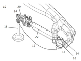
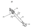
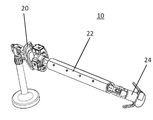
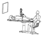
도 1은 사용자의 손에 의해 작동되는 본 컨트롤러를 도시한다.
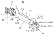
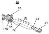
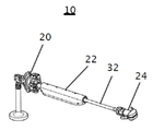
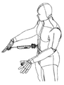
도 2는 본 컨트롤러의 세 부분의 상대적 이동을 도시한다.
도 3a 내지 도 3d는 본 컨트롤러의 전후(도 3a 및 도 3c) 및 수술 장치의 텔레스코픽 샤프트의 대응하는 인-아웃(in and out)(줌(zoom))(도 3b 및 도 3d)을 도시한다.
도 4a 및 도 4b는 본 컨트롤러의 좌우 이동(도 4a) 및 수술 장치의 샤프트의 대응하는 회전(도 4b)을 도시한다.
도 5a 및 도 5b는 본 컨트롤러의 상하 이동(도 5a) 및 수술 장치의 조향 가능한 샤프트의 대응하는 변형(도 5b)을 도시한다.
도 6a 내지 도 6d는 본 컨트롤러의 손가락 레버의 각(angular) 인-아웃 이동(도 6a 및 도 6c) 및 수술 장치의 조직 조작 단부의 대응하는 개방-폐쇄 조(open-close jaw)의 이동(도 6b 및 도 6d)을 도시한다.
도 7a 및 도 7b는 본 컨트롤러의 손가락 레버의 회전 이동(도 7a) 및 수술 장치의 조직 조작 단부의 대응하는 회전(도 7b)을 도시한다.
도 8a 내지 도 8d는 본 컨트롤러의 손가락 인터페이스 부분의 상하 이동(도 8a 및 도 8c) 및 수술 장치의 조향 가능한 샤프트의 대응하는 상하 변형(도 8b 및 도 8d)을 도시한다.
도 9a 내지 도 9d는 본 컨트롤러의 손가락 인터페이스 부분의 측면 이동(도 9a 및 도 9c) 및 수술 장치의 조향 가능한 샤프트의 대응하는 측면 변형(도 9b 및도 9d)을 도시한다.
도 10a 및 도 10b는 본 컨트롤러의 제 1 부분의 각(angular) 이동 센서를 도시한다.
도 11a 및 도 11b는 본 컨트롤러의 제 2 부분의 선형 이동 센서를 도시한다.
도 12a 및 도 12b는 본 컨트롤러의 제 3 부분의 각(angular) 이동 센서를 도시한다.
도 12c는 사용자가 여러 수술 도구들 사이에서 제어를 전환할 수 있게 하는 버튼(button)을 도시한다.
도 13a 내지 도 13c는 본 컨트롤러의 다양한 장착 구조를 도시한다.
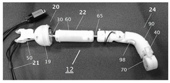
도 14a 내지 도 14c는 본 발명의 교시에 따라 구성된 프로토 타입 컨트롤러의 사진이다.The invention is described herein by way of example only with reference to the accompanying drawings. With specific reference to the drawings, the details shown are by way of example only and for purposes of illustrative discussion of the preferred embodiments of the invention, and are the most useful and easily understood description of the principles and conceptual aspects of the invention. It is emphasized that it is suggested as a cause for providing what is believed to In this regard, it is not intended to represent structural details of the invention in more detail than necessary for a basic understanding of the invention, and the description provided with the drawings is directed to those skilled in the art as to how some aspects of the invention may be implemented. To clarify.
In the drawing,
1 shows the present controller operated by a user's hand.
2 shows the relative movement of the three parts of this controller.
3A-3D show the front and rear of the present controller (FIGS. 3A and 3C) and the corresponding in and out (zoom) of the telescopic shaft of the surgical device (FIGS. 3B and 3D). .
4A and 4B show the lateral movement of the present controller (FIG. 4A) and the corresponding rotation of the shaft of the surgical device (FIG. 4B).
5A and 5B show the up and down movement of the present controller (FIG. 5A) and the corresponding deformation of the steerable shaft of the surgical device (FIG. 5B).
6A-6D show the angular in-out movement of the finger lever of the present controller (FIGS. 6A and 6C) and the movement of the corresponding open-close jaw of the tissue manipulation end of the surgical device (FIGS. 6A-6C). 6b and 6d).
7A and 7B show the rotational movement of the finger lever of the present controller (FIG. 7A) and the corresponding rotation of the tissue manipulation end of the surgical device (FIG. 7B).
8A-8D show the up and down movement of the finger interface portion of the present controller (FIGS. 8A and 8C) and the corresponding up and down deformation of the steerable shaft of the surgical device (FIGS. 8B and 8D).
9A-9D show the lateral movement of the finger interface portion of the present controller (FIGS. 9A and 9C) and the corresponding lateral deformation of the steerable shaft of the surgical device (FIGS. 9B and 9D).
10A and 10B show angular movement sensors of the first part of the present controller.
11A and 11B show the linear motion sensor of the second part of the present controller.
12A and 12B show angular movement sensors of the third part of the present controller.
12C illustrates a button that allows a user to switch control between various surgical instruments.
13A-13C show various mounting structures of the present controller.
14A-14C are photographs of prototype controllers constructed in accordance with the teachings of the present invention.
본 발명은 내시경, 복강경 및 로봇 도구 시스템을 포함하는 하나 또는 그 이상의 수술 도구의 작동을 국부적으로 또는 원격으로 제어하기 위해 사용될 수 있는 컨트롤러에 관한 것이다. 구체적으로, 본 발명은 수술 도구에 직접 또는 무선으로 (또는 통신 네트워크를 통해) 부착되어, 그 동작을 제어하거나, 원격으로 (수술실(operating theater) 내부 또는 외부에서) 사용되어, 로봇 수술 시스템을 제어할 수 있다.The present invention relates to a controller that can be used to locally or remotely control the operation of one or more surgical instruments, including endoscopes, laparoscopics, and robotic tool systems. Specifically, the present invention is attached to a surgical instrument directly or wirelessly (or via a communication network) to control its operation or remotely (either inside or outside an operating theater) to control a robotic surgical system. can do.
본 발명의 원리 및 작동은 도면 및 첨부된 설명을 참조하여 더 잘 이해될 수 있다.The principles and operation of the present invention can be better understood with reference to the drawings and the accompanying description.
본 발명의 적어도 하나의 실시형태를 상세히 설명하기 전에, 본 발명은 다음의 설명에서 설명되거나 실시형태에 의해 예시된 세부 사항으로 본 발명의 적용을 제한하지 않음을 이해해야 한다. 본 발명은 다른 실시형태가 가능하거나, 다양한 방식으로 실시 또는 수행될 수 있다. 또한, 본 명세서에서 사용된 어구 및 용어는 설명의 목적을 위한 것이며, 제한하는 것으로 간주되어서는 안된다는 것을 이해해야 한다.Before describing at least one embodiment of the invention in detail, it is to be understood that the invention does not limit the application of the invention to the details set forth in the following description or illustrated by the embodiments. The invention is capable of other embodiments or of being practiced or carried out in various ways. Also, it is to be understood that the phraseology and terminology used herein is for the purpose of description and should not be regarded as limiting.
수술 도구용 컨트롤러는 당업계에 잘 알려져 있으며, 기계식, 모터식 또는 로봇식 도구를 제어하는데 사용된다. 이러한 컨트롤러는 신체 내에 수술 기구를 정확하게 위치시키고 제어하는데 사용될 수 있지만, 부피가 크고 작동하기 어려울 수 있으며, 종종 마스터하기 위해 오랜 훈련 기간이 필요하다.Controllers for surgical instruments are well known in the art and are used to control mechanical, motorized or robotic instruments. Such controllers can be used to accurately position and control surgical instruments within the body, but can be bulky and difficult to operate and often require long training periods to master.
본 발명자는 본 발명을 실시하기 위해 본 발명을 축소시키면서, 하나 또는 그 이상의 수술 도구를 쉽고 자연스럽게 제어하는데 사용될 수 있는 수술 도구 컨트롤러를 설계하기 시작했다. 본 컨트롤러는 사용자 팔, 손 및 손가락의 자연스러운 움직임을 수술 도구의 특정 움직임 및 작동으로 변환하도록 설계되었다. 이를 통해 사용자는 컨트롤러의 특정 부분의 움직임에 주의를 기울이지 않고도 손을 자연스럽게 이동하고 지향할 수 있다. 다시 말해, 사용자는 수술 도구의 효과적인 이동을 수행하기 위해, 컨트롤러의 각 부분을 개별적으로 제어할 필요가 없고, 팔, 손 및 손가락의 하나의 유체 및 협력된 움직임을 사용하여, 수술 도구를 위치시키고 작동시킨다. 본 컨트롤러는 길이 방향으로 배열된 몇몇 부분을 포함하고, 각각은 하나 또는 그 이상의 축으로 독립적으로 움직일 수 있기 때문에, 사람의 팔, 손 및 손가락에 의해 생성된 임의의 복잡한 움직임은 본 컨트롤러에 의해 정확하게 추적될 수 있고, 하나 또는 그 이상의 수술 기구의 유사하고 복잡한 움직임으로 변환될 수 있다.The inventors have begun designing surgical instrument controllers that can be used to easily and naturally control one or more surgical instruments while minimizing the invention to practice the invention. The controller is designed to convert the natural movements of the user's arms, hands and fingers into specific movements and operations of the surgical tool. This allows the user to naturally move and orient his hands without paying attention to the movement of certain parts of the controller. In other words, the user does not have to individually control each part of the controller to perform the effective movement of the surgical tool, and uses one fluid and coordinated movement of the arms, hands and fingers to position the surgical tool and It works. Since the controller includes several parts arranged in the longitudinal direction, each of which can move independently in one or more axes, any complex movements generated by the arms, hands and fingers of a person can be accurately corrected by the controller. It can be tracked and translated into similar and complex movements of one or more surgical instruments.
본 발명의 컨트롤러는 구체적으로 다음을 제공하도록 설계되었다:The controller of the present invention is specifically designed to provide:
(i) 사용자의 손과 손가락의 자연스러운 움직임을 하나 또는 그 이상의 수술기구의 정확한 움직임으로 변환함.(i) converts the natural movements of the user's hands and fingers into the correct movement of one or more surgical instruments.
(ii) 사용자가 빠르게 마스터함.(ii) the user masters quickly.
(iii) 사용자가 휴대할 수 있는 작고 가벼운 인터페이스 제공함.(iii) Provides a small and lightweight interface for the user to carry.
(iv) 발 페달 사용이 불필요함.(iv) No use of foot pedals.
(v) 임의의 유형의 수술 도구에 대한 보편적 제어를 제공함.(v) provide universal control of any type of surgical instrument.
따라서, 본 발명의 일 측면에 따르면, 수술 도구용 컨트롤러가 제공된다.Thus, according to one aspect of the invention, there is provided a controller for surgical instruments.
본 명세서에서 사용된 어구 "수술 도구"는 수술(개방 또는 최소)에 사용되는 임의의 도구를 지칭하며, 수술시 조작, 관찰 또는 그렇지 않으면 보조하기 위한 것이다. 수술 도구의 예에는 이에 제한되는 것은 아니지만, 그래스퍼, 바늘, 카메라, 석션, 다이아써미아 훅(diathermia hook) 또는 양극성 그래스퍼와 같은 이펙터를 구비한 내시경(예를 들어, 위 내시경, 결장 내시경, 복강경)을 포함한다. 내시경은 하나 또는 그 이상의 이펙터 단부로 종결되는 강성, 가요성 또는 조향 가능한 샤프트를 포함할 수 있다.As used herein, the phrase “surgical tool” refers to any tool used for surgery (open or minimal) and is intended to be manipulated, observed or otherwise assisted during surgery. Examples of surgical instruments include, but are not limited to, endoscopes with effects such as graspers, needles, cameras, suctions, diathemia hooks, or bipolar grapers (e.g., gastroscopes, colonoscopy, laparoscopes). ). The endoscope may include a rigid, flexible or steerable shaft that terminates with one or more effector ends.
내시경 도구는 작은 직경의 전달 포트(예를 들어, 트로카)를 통해 전달되고, 해부학적으로 제한된 공간에서 이용되므로, 신체 외부에 위치된 제어장치를 사용하고, 신체 내부에서 편향될 수 있는 조향 가능한 샤프트를 구비한 내시경을 사용하는 것이 유리할 수 있다. 이러한 조향은 조작자가 신체 내에 내시경을 안내하고, 원위에 장착된 이펙터를 해부학적 주요지점(landmark)에 정확하게 위치시킬 수 있도록 한다. 조향 가능한 도구는 전형적으로 샤프트의 길이에서 연장하고 조향 가능한 부분의 원위 단부 또는 원위 팁에서 종결되는 하나 또는 그 이상의 제어 와이어를 사용한다.The endoscopic tool is delivered through a small diameter delivery port (e.g. trocar) and is used in anatomically confined spaces, allowing for steering which can be deflected inside the body, using controls located outside the body. It may be advantageous to use an endoscope with a shaft. This steering allows the operator to guide the endoscope in the body and to accurately position the distal mounted effector at an anatomical landmark. Steerable tools typically use one or more control wires that extend in the length of the shaft and terminate at the distal end or distal tip of the steerable portion.
본 발명의 컨트롤러는 상호 연결된 제 1, 제 2 및 제 3 부분을 갖는 세장형 몸체를 포함한다. 제 1 부분은 지지체(예를 들어, 사용자의 의자, 침대, 벨트)에 부착될 수 있는 근위 단부 및 제 2 부분에 연결된 원위 단부를 포함한다. 이러한 연결은 제 2 부분이 제 1 부분에 대해 이동할 수 있게 한다. 제 3 부분은 제 3 부분이 제 2 부분에 대해 이동할 수 있도록 구성된 커넥터를 통해 제 2 부분에 연결된다. 제 3 부분은 사용자의 손 및/또는 손가락을 통해 결합 가능한 제어를 포함한다.The controller of the present invention includes an elongated body having first, second and third portions interconnected. The first portion includes a proximal end that can be attached to a support (eg, a user's chair, bed, belt) and a distal end connected to the second portion. This connection allows the second part to move relative to the first part. The third portion is connected to the second portion via a connector configured to allow the third portion to move relative to the second portion. The third part includes controls that are engageable through the user's hand and / or fingers.
본 컨트롤러는 바람직하게는 전동 수술 도구와 함께 이용되고, 유선 또는 무선 인터페이스를 통해 이에 기능적으로 부착되지만, 컨트롤러가 무동력 수술 도구의 제어 유닛과 직접(및 기계적으로) 인터페이스되도록 설계된 근위 단부를 포함하는 구조 또한 본 명세서에서 예상된다.The controller is preferably used with a powered surgical tool and is functionally attached to it via a wired or wireless interface, but includes a proximal end designed to interface the controller directly (and mechanically) with the control unit of a powered surgical tool. It is also contemplated herein.
따라서, 본 컨트롤러는 각각 본 컨트롤러에 기능적으로 연결된 수술 도구의 상이한 기능을 제어할 수 있는 3 개의 상호 연결되고 독립적으로 움직일 수 있는 부분을 포함한다.Thus, the controller includes three interconnected and independently movable parts, each of which can control different functions of a surgical tool functionally connected to the controller.
이하, 도면을 참조하면, 도 1은 본 명세서에서 컨트롤러(10)로 지칭되는 본 컨트롤러를 도시한다.Referring now to the drawings, FIG. 1 shows a present controller, referred to herein as a
컨트롤러(10)는 근위 단부(14) 및 원위 단부(16)를 갖는 세장형 몸체(12)를 포함한다. 도 1 및 도 2에 도시된 구성에서, 근위 단부(14)는 지지 포스트(18)에 연결된다. 이러한 지지 포스트(18)는 의자, 침대 또는 임의의 안정된 구조에 부착될 수 있다. 대안적으로, 지지 포스트(18)는 사용자의 벨트에 장착될 수 있다.The
세장형 본체(12)는 3 개의 부분, 제 1 부분(20), 제 2 부분(22) 및 제 3 부분(24)을 포함한다. 제 3 부분(24)은 도 1에서 사용자의 손가락에 의해 움켜진 손/손가락 인터페이스(26)를 포함한다.The
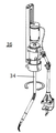
도 2는 부분(20) 부분(22) 및 부분(24) 각각의 이동을 도시한다. 부분(20)은 세장형 몸체(12)의 부분(22) 및 부분(24)의 상하, 좌우 이동을 가능하게 하는 짐벌형 조인트(gimbal-like joint)(28)를 포함한다. 부분(22)은 커넥터(30)를 통해 부분(20)의 짐벌 조인트(28)에 연결된다. 부분(22)은 레일(32)(도 3a 및 도 3c)의 이동을 측정하는 선형 센서를 위한 하우징으로서 기능하는 커버(31)를 포함한다.2 shows the movement of each of the
부분(24)은 부분(22)의 인-아웃으로 이동할 수 있는 레일(32)(도 3a 및 도 3c)에 장착된다(줌 인-아웃). 반면, 손/손가락(26)이 부분(22)에 대해 상하 및 좌우로 이동할 수 있는 동안, 부분(24)은 또한 부분(20)에 대해 부분(22)과 함께 롤링될 수 있다.The
세장형 몸체는 길이가 100-300 mm이고, 직경이 10-30 mm일 수 있다. 세장형 몸체의 선형 이동 범위(완전히 수축된 상태와 완전히 연장된 상태 사이의 델타)는 50-250mm일 수 있다. 부분(22)은 ±60도의 범위로 상/하 각운동하고, 좌우 ±90도 범위로 롤링할 수 있다. 부분(24)은 ±90도의 범위로 상/하 각운동하고, 좌우 ±90도 범위로 롤링할 수 있다. 손가락 인터페이스(26)는 ±30도로 롤링할 수 있으며, 레버(40)는 ±30도로 개폐할 수 있다.The elongated body may be 100-300 mm long and 10-30 mm in diameter. The linear range of movement of the elongate body (delta between fully retracted and fully extended) can be 50-250 mm. The
도 3a 내지 도 9b는 컨트롤러(10)의 다양한 이동과 수술 도구의 대응하는 이동을 도시한다.3A-9B illustrate various movements of the
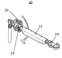
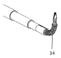
도 3a 내지 도 4d는 컨트롤러(10)의 '줌(zoon)' 기능을 도시한다. (도 3a 및 도 3c에 각각 도시된 바와 같이) 부분(22)에 대한 부분(24)의 수축 및 연장은 수술 도구 (36)의 텔레스코픽 샤프트(34)를 수축 및 연장시킨다. 이러한 이동은 사용자가 신체 내에서 샤프트(34)를 연장/수축시켜, 조직 부위에 이펙터 단부(38)를 더 잘 위치시킬 수 있게 한다. 부분(24)의 선형 이동 범위는 전형적으로 0-200 mm이다.3A-4D illustrate the 'zoon' function of the
부분(24)과 샤프트(34) 사이의 이동 비율은 1 : 1(절대적 제어)일 수 있거나 2 : 1, 3 : 1 등 일 수 있거나 그 반대일 수 있다(상대적 제어).The rate of movement between the
도 4a 및 도 4b는 부분(20)(짐벌 조인트(28)일 수 도)에 대한 부분(22)의 측면(좌-우) 이동(도 4a)을 도시하고, 수술 도구(36)의 조향 가능한 샤프트의 대응하는 좌우 회전(도 4b)를 도시한다. 이 도구의 이동에는 상대적 제어 및 절대적 제어가 모두 사용될 수 있다.4A and 4B show the lateral (left-right) movement (FIG. 4A) of the
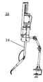
도 5a 및 도 5b는 부분(20)(짐벌 조인트(28)일 수 도)에 대한 부분(22) 및 부분(24)의 상하 이동(도 5a) 및 수술 도구(36)의 조향 가능한 샤프트(34)의 대응하는 상하 변형(도 5b)을 도시한다. 이 도구의 이동에는 상대적 및 절대적 제어를 모두 사용할 수 있다.5A and 5B show a
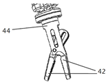
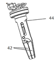
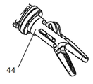
도 6a 내지 도 6d는 인터페이스(26)의 손가락 레버(40)의 이동을 도시한다. 레버(40)의 각 개방(angular opening)(도 6a)은 (수술 도구 샤프트의 원위 단부에 부착된) 그래스퍼(44)의 조(jaw)(42)를 개방(도 6b)하는 반면, 레버(40)의 각 폐쇄(angular closing)(도 6c)는 그래스퍼(44)의 조(42)를 폐쇄(도 6d)한다. 손가락 레버(40)는 ±30도로 개방되거나 폐쇄된다. 손가락 레버(40)의 이동과 그래스 퍼(44)의 조(42) 사이에서 1 : 2의 각도 이동(레버 : 조)의 상대적 제어가 이용될 수 있다.6A-6D illustrate the movement of the
도 7a 및 도 7b는 부분(24)의 손가락 세그먼트의 회전(도 7a) 및 그래스퍼 (44)의 대응하는 회전(도 7b)을 도시한다. 부분(24)의 회전과 그래스퍼(44)의 회전 사이에서 최대 1 : 7 스케일의 각 이동(손가락 레버 : 조)의 상대적 제어가 이용될 수 있다.7A and 7B show the rotation of the finger segment of portion 24 (FIG. 7A) and the corresponding rotation of grasper 44 (FIG. 7B). Relative control of angular movement (finger lever: jaws) of up to 1: 7 scale can be used between the rotation of the
도 8a 내지 도 8d는 부분(22)에 대한 부분(24)의 상하 이동(도 8a 및 도 8c 각각) 및 샤프트(34)의 원위 조향 가능한 부분의 대응하는 상하 변형(도 8b 및 도 8d 각각)을 도시한다. 부분(24)의 이동과 샤프트(34)의 원위 조향 가능한 부분의 이동 사이에서 상대적 및 절대적 제어가 이용될 수 있다.8A-8D show the up and down movement of the
도 9a 내지 도 9d는 부분(20)에 대한 부분(22)과 함께 부분(24)의 측면 경사(tilt)(롤링)(도 9a 및 도 9c) 및 샤프트(34)의 원위 조향 가능한 부분의 대응하는 좌우 변형(도 9b 및 도 9d)을 도시한다. 부분(24)의 이동과 샤프트(34)의 원위 조향 가능한 부분의 이동 사이에서 상대적 및 절대적 제어가 이용될 수 있다.9A-9D correspond to the side tilts (rolling) of the
컨트롤러(10)는 수술 도구에 물리적으로 연결될 수 있고, 대안적으로, 컨트롤러(10)는 외과 의사 벨트에 있거나 삼각대를 통해 외과 의사 시트 또는 환자 침대에 연결될 수 있다. 컨트롤러와 전동 수술 도구 사이의 통신은 물리적 유선 또는 무선으로 (RF/적외선/광 통신을 통해) 연결되어, 샤프트, 이펙터 단부 등의 이동을 작동시키는 하나 또는 그 이상의 모터를 제어할 수 있다.The
후자의 구조에서, 컨트롤러(10)는 손가락 레버(40) 뿐만 아니라 부분(20), 부분(22) 및 부분(24) 사이의 상대 이동을 측정하는 세장형 몸체(12)를 따라 위치된 몇몇 센서를 포함한다.In the latter structure, the
도 10a 내지 도 12b는 손가락 레버(40)(도 12a 내지 도 12b) 뿐만 아니라 부분(20) 부분(22) 및 부분(24)(도 10a 내지 도 10b, 도 11a 내지 도 11b, 및 도 12a 내지 도 12b)에 대한 센서 배열을 도시한다.10A-12B show the
도 10a 및 도 10b는 컨트롤러(10)의 부분(20)을 도시한다. 부분(20)의 근위 단부는 클램프(50)를 통해 지지 포스트(18)에 연결된다. 부분(20)의 원위 단부는 조인트(28)를 통해 부분(22)에 회전 가능하게 연결된다. 클램(50)은 슬롯(52)에 의해 외부 짐벌 아크(outer gimbal arc)(50)에 연결된다. 슬롯(52)은 지지 포스트(18)에 대해 외과 의사가 짐벌 아크(50)를 회전시킬 수 있게하여, 외과 의사가 부분(20)의 방향을 조절할 수 있게 한다. 짐벌링(gimbal ring)(53)은 외부 짐벌(51)에 회전 가능하게 연결된다. 회전 센서(55)는 짐벌(53)에 연결되고, 부분(22)의 좌/우 이동을 측정한다. 내부 실린더(56)는 링(53)에 회전 가능하게 연결된다. 실린더(56)의 회전 축은 링(53)을 외부 아크(51)에 연결하는 샤프트에 수직한다. 회전 센서(54)는 실린더(56)의 샤프트에 연결되고, 부분(22)의 상하 이동을 측정한다.10A and 10B show a
샤프트(30)는 실린더(56)에 회전 가능하게 연결된다. 회전 센서(58)는 샤프트(30)에 연결되고, 부분(22)과 함께 부분(24)의 경사(롤링) 이동을 측정한다.The
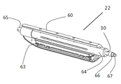
도 11a 및 도 11b는 컨트롤러(10)의 부분(22)을 도시한다. 샤프트(30)는 부분(22)의 근위 단부에서 우측에 도시된다. 상술한 바와 같이, 샤프트(30)는 형상 축 단부(67)을 갖는 중앙 실린더(56)에 위치된 회전 측정 센서(58)에 연결된다. 부분(22)의 회전(손가락 부분(24)의 손목 경사(tilt)를 통해)을 통해 샤프트(30)를 함께 회전시키며, 손가락 경사의 정도는 회전 센서(58)를 통해 측정된다.11A and 11B show a
센서(63)는 샤프트(65)의 선형 운동을 측정한다. 샤프트(65)는 부분(22)의 중공 몸체(64)에 신축 방식(telescopically mounted)으로 장착된다. 샤프트(65)가 몸체(64)에 대해 앞뒤로 이동할 때, 슬라이더(68)를 운반하고, 선형 센서(63)는 부분(22)에 대해 슬라이더의 위치를 측정한다. 커버(60)는 선형 센서(63), 몸체(64) 및 샤프트(30)를 위한 하우징으로서 기능한다. 샤프트(65)는 부분(22)을 부분(24)에 연결한다.The
본 명세서에서 설명된 센서는 ALPS의 Linear Type RDC10 Series와 같은 전기 선형 전위차계(electric linear potentiometer), Melexis Technologies NV의 LX90393SLW-ABA-011-RE와 같은 자기 홀 효과 센서(magnetic Hall Effect sensor) 또는 Bourns Inc의 3590S-2-103L과 같은 다중 회전 전위차계(multi rotational potentiometer)일 수 있다.The sensors described herein include electric linear potentiometers such as the Linear Type RDC10 Series from ALPS, magnetic Hall Effect sensors such as the LX90393SLW-ABA-011-RE from Melexis Technologies NV, or Bourns Inc. It may be a multi rotational potentiometer such as 3590S-2-103L.
컨트롤러(10)를 작동시키기 위해, 사용자는 부분(24)을 잡고(grasp), 부분(22) 및 부분(24)을 원하는 공간 위치(상/하, 회전, 좌우, 전방 후방)로 이동시킨다. 컨트롤러(10)의 이동은 이에 의해 제어되는 수술 도구(들)의 이동에 의해 모방된다. 사용자는 또한 레버(40)를 통해 이펙터 단부(예를 들어, 그래스퍼)를 동시에 제어할 수 있다. 부분(24)은 또한 부분(20)에 대해 기울어지고 및 회전될 수 있다. 레버의 작동 및 부분(24)의 이동은 다른 부분의 이동과 동시에 또는 독립적으로 영향을 받을 수 있다.In order to operate the
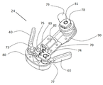
부분(24)의 샤프트(79)는 부분(22)의 원위 샤프트(65)에 고정된다. 몸체(90)는 샤프트(81)를 통해 샤프트(79)에 연결된다. 몸체(90)는 몸체(90)에 고정된 센서(78)를 통해 측정된 회전으로 샤프트(81) 주위에서 회전할 수 있고; 샤프트(81)는 센서(78)의 회전 부분을 통과한다. 몸체(90)가 회전할 때, 회전 센서는 부분(24)의 상하 이동을 측정한다.The
몸체(70)는 샤프트(82)를 통해 몸체(90)에 연결되고, 손가락 제어를 통해 샤프트(82) 주위에서 회전 가능하다. 회전 센서(79)는 회전 센서(89)를 통과하는 샤프트(82)와 함께 몸체(70)에 고정된다. 몸체(70)가 회전할 때, 회전 센서(79)는 부분(24)의 롤링 이동을 측정한다.
레버(40)는 몸체(70)의 원위 단부에 위치하고, 샤프트(73) 및 샤프트(74)를 중심으로 회전한다. 레버(40)는 기어(75) 및 기어(76)를 통해 상호 연결되어, 레버 (40)의 동일한 움직임을 보장하면서 사용자가 레버 중 하나에만 힘을 가하여 레버 (40)를 개폐할 수 있게 한다. The
기어(85)(레버(40)의 부품)는 회전 센서(77)를 통해 차례로 회전하는 샤프트(74)에 견고하게 연결된 기어(86)와 맞물린다. 샤프트(74)가 회전할 때, 회전 센서(79)는 레버(40)의 각 운동을 측정한다.The gear 85 (part of the lever 40) engages with the
기어(85) 및 기어(86)는 직경이 동일하거나 상이할 수 있다. 이를 통해 개폐 동작에 대해 다른 감도(sensitivity)를 선택할 수 있다. 스프링(80)은 샤프트(73) 및 샤프트(74)를 연결한다. 레버(40)에 폐쇄력이 가해질 때, 스프링(80)은 대응하는 개방력을 가하여, 사용자에게 레버(40)의 이동 감도를 향상시키고, 폐쇄력이 해제될 때, 레버가 자동으로 개방되게 한다.
전술한 바와 같이, 컨트롤러(10)는 고정구(삼각대, 의자, 침대)에 장착되거나 또는 사용자(벨트 또는 하니스(harness)의 사용을 통해)에 직접 장착될 수 있다.As mentioned above, the
도 13a 내지 도 13c는 베드 프레임(80)(도 13a) 및 사용자(82)(도 13a 및 도 13b)에 컨트롤러(10)의 장착을 도시한다.13A-C illustrate the mounting of the
도 13a는 사용자(예를 들어, 외과 의사)가 의자에 부착된 적어도 하나의 컨트롤러(10)를 가진 의자에 앉아있는 구성을 도시한다. 컨트롤러(10)의 세장형 몸체(12)는 일반적으로 외과 의사의 팔꿈치 아래에 위치된 부분(20) 및 외과 의사의 손가락에 위치된 부분(24)과 함께 외과 의사 팔뚝 아래 및 이를 따라 위치된다. 이 구조에서, 복강경 카메라에 연결된 비디오 스크린을 통해 해부 위치를 보면서 컨트롤러(10)는 외과 의사에 의해 쉽고 자연스럽게 이동할 수 있다.FIG. 13A illustrates a configuration in which a user (eg, a surgeon) sits in a chair with at least one
도 13b는 적어도 하나의 컨트롤러(10)가 벨트를 통해 외과 의사에게 부착된 구조를 도시한다. 컨트롤러(10)의 세장형 몸체(12)는 일반적으로 외과 의사의 팔꿈치 아래에 위치된 부분(20) 및 외과 의사의 손가락에 위치된 부분(24)과 함께 외과 의사 팔뚝 아래 및 이를 따라 위치된다. 이 구조에서, 복강경 카메라에 연결된 비디오 스크린을 통해 해부 위치를 보면서, 도 13c에 도시된 바와 같이 수술실에서 자유롭게 움직일 수 있으면서, 컨트롤러(10)는 외과 의사에 의해 쉽고 자연스럽게 이동할 수 있다.FIG. 13B shows a structure in which at least one
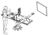
도 13c는 외과 의사 벨트에 부착된 2 개의 컨트롤러(10)의 설정(set up)을 도시한다. 외과 의사는 비디오 화면을 통해 해부 위치를 보면서 환자의 침대 근처에 서서 작동한다. 이 구성의 장점 중 하나는 의사가 환자와 가까이 있다는 것이다.13C shows the set up of two
본 발명의 하나 또는 그 이상의 컨트롤러(10)는 임의의 유형의 최소 침습 수술(minimally invasive procedure) 또는 완전 개방 수술(fully open procedure)에서 이용될 수 있다. 하기는 최소 침습 수술 절차에서 복강경 도구를 제어하기 위한 컨트롤러(10)의 사용을 설명한다.One or
조직 벽에 여러 개의 절개부를 형성하여, 여러 개의 접근 부위를 생성한다. 그런 다음 각 부위를 사용하여, 트로카를 위치시키고, 트로카를 통해 이펙터 단부가 체강(body cavity) 내에 위치할 때까지 수술 도구(그래스퍼, 커터, 카메라)를 전진시킨다.Several incisions are made in the tissue wall, creating multiple access sites. Each site is then used to position the trocar and advance the surgical instrument (grapher, cutter, camera) through the trocar until the effector end is in the body cavity.
수술 도구는 모터 팩이 이의 근위(체외) 단부에 연결된 로봇 도구일 수 있다. 하나 또는 그 이상의 컨트롤러(10)는 고정구 및/또는 외과 의사에 장착되고, 컨트롤러(들)의 운동이 수술 도구의 운동과 정확하게 배향되도록 컨트롤러를 테스트한다. 하나 또는 그 이상의 수술 도구가 정확하게 배향되지 않은 경우, 외과 의사는 수동 또는 자동으로(모터를 통해) 수술 도구(들)를 올바른 방향으로 회전시킬 수 있다. 방향이 설정되면 컨트롤러(들)가 수술을 위해 준비된 것이다.The surgical tool may be a robotic tool with a motor pack connected to its proximal (external) end. One or
예를 들어 하나의 수술 도구(예를 들면, 그래스퍼)가 외과 의사 쪽에서 활용되고, 다른 도구(예를 들어,: 카메라)가 반대 쪽에서 활용되는 경우와 같이 수술 도구의 방향이 다른 방향으로 설정해야 하는 수술이 필요한 경우, 외과 의사는 이러한 설정을 위해 각 컨트롤러를 설정할 수 있다. For example, one surgical tool (e.g. grasper) is used on the surgeon's side and the other tool (e.g. camera) is used on the other side. If surgery is needed, the surgeon can set up each controller for this setup.
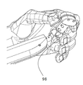
외과 의사는 둘 또는 그 이상의 컨트롤러(10)를 사용하여, 둘 또는 그 이상의 수술 도구를 제어할 수 있다. 대안적으로, 외과 의사는 단일 컨트롤러(10)를 사용하여 둘 또는 그 이상의 수술 도구를 순차적으로 제어할 수 있다. 컨트롤러(10)는 다이얼로그 버튼(98)(도 12c)을 포함하여, 도구들 사이의 전환을 가능하게 한다. 다이얼로그 버튼(98)은 컨트롤러(10)와 수술 도구 사이의 통신을 제어한다. 이 버튼이 눌러지면, 수술 도구로부터 컨트롤러(10)를 연결하거나 해제할 수 있거나, 여러 도구들 사이의 전환을 허용할 수 있다. 사용자가 도구 사이에서 도구를 전환하면, 해제된 공구는 마지막으로 제어된 위치에 유지된다. 이 도구로 복귀할 때, 외과 의사는 이 도구의 '일시 정지된' 위치와 일치하도록 컨트롤러(10)의 방향을 재설정할 필요가 없다. 이러한 상대적 제어 방식을 통해, 외과 의사는 컨트롤러를 해제(이동(let go))하고, 보다 편안한 팔 위치를 선택한 후 컨트롤러를 다시 결합하고, 해제 전에 도구 위치를 컨트롤러 위치와 일치시키지 않고도 수술을 진행할 수 있다.The surgeon may use two or
상대적 제어는 또한 외과 의사가 수술 도구에 대한 제어를 갖는 다이얼로그 버튼을 활성화하여 임의의 수의 외과 의사 사이에서 제어를 전환할 수 있게 한다. 외과 의사의 컨트롤러의 공간적 위치가 수술 도구의 공간적 위치와 일치할 필요가 없기 때문에, 이러한 제어의 전달은 원활할 수 있다.Relative control also allows the surgeon to activate a dialog button with control over the surgical instrument to switch control between any number of surgeons. Since the spatial position of the surgeon's controller does not have to match the spatial position of the surgical instrument, the transfer of such control can be smooth.
절대적 제어 하에서, 외과 의사는 컨트롤러의 위치와 공구의 위치를 일치시켜야한다. 안전 알고리즘이 있는 소프트웨어는 한 컨트롤러 위치에서 다른 위치로의 이동을 연결하는 부드럽고 필터링된 이동 경로를 적용하여, 그 차이를 보완할 수 있다.Under absolute control, the surgeon must match the position of the tool with the position of the controller. Software with safety algorithms can compensate for the difference by applying smooth, filtered travel paths that connect movement from one controller location to another.
따라서, 본 발명은 사용자에 의해 소지되거나 어느 곳에나 배치될 수 있는 소형의 경량 컨트롤러를 제공한다. 본 컨트롤러는 경량이고, 소형이지만 6 축에서 사람 손의 가장 복잡한 움직임을 따를 수 있다. 이것은 하나의 컨트롤러 부분이 다른 컨트롤러 부분에 대해 큰(cm) 및 작은(micron) 범위의 움직임을 모두 감지하기위한 센서 메커니즘을 갖는 조인트 인터페이스에 의해 달성된다.Accordingly, the present invention provides a compact, lightweight controller that can be carried by the user or placed anywhere. The controller is lightweight and compact but can follow the most complex movements of the human hand in six axes. This is accomplished by a joint interface where one controller part has a sensor mechanism for sensing both large (cm) and small (micron) ranges of motion relative to the other controller part.
전형적인 콘솔 타입 인터페이스/컨트롤러는 외과 의사 앞에 컨트롤을 배치하지만, 본 컨트롤러는 수술 도구와 동일한 일반 방향으로만 배치하면 된다. 컨트롤러의 근위 단부는 전형적으로 외과 의사의 팔꿈치 근처에 위치되고 원위 단부는 외과 의사 손가락 근처에 위치된다.A typical console type interface / controller places the control in front of the surgeon, but the controller only needs to be placed in the same general direction as the surgical tool. The proximal end of the controller is typically located near the surgeon's elbow and the distal end is located near the surgeon's finger.
본 컨트롤러는 수술 도구에 대한 상대 제어를 가능하게 하여, 외과 의사가 수술 중이라도 컨트롤러를 작동시키기 위해 가장 인체 공학적인 위치를 선택할 수있게 한다. 상대 제어의 또 다른 이점은 컨트롤러 재배치에 의해 중단되는 일련의 작은 움직임을 사용하여, 넓은 범위의 이동에 영향을 줄 수 있기 때문에, 컨트롤러를 경량이고 소형화할 할 수 있다는 점이다.The controller allows relative control of the surgical tool, allowing the surgeon to select the most ergonomic position to operate the controller even during surgery. Another advantage of relative control is that the controller can be made light and compact because it can affect a wide range of movements by using a series of small movements interrupted by controller relocation.
임의의 수의 본 컨트롤러는 하나 또는 그 이상의 사용자에 의해 동시에 사용되어 임의의 수의 수술 도구를 제어할 수 있다.Any number of present controllers can be used simultaneously by one or more users to control any number of surgical instruments.
본 명세서에 사용된 용어 "약"은 ± 10 %를 지칭한다.The term "about" as used herein refers to ± 10%.
본 발명의 추가의 목적, 장점 및 신규한 특징은 하기 실시예를 시험하면서, 당업자에게 명백하게 될 것이나, 이는 발명을 제한하려는 것은 아니다.Additional objects, advantages and novel features of the invention will become apparent to those skilled in the art upon examination of the following examples, which are not intended to limit the invention.
[[ 실시예Example ]]
상기 설명과 함께, 본 발명을 비-제한적인 방식으로 설명하는 하기 실시예를 참조한다.In conjunction with the above description, reference is made to the following examples illustrating the invention in a non-limiting manner.
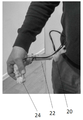
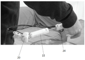
본 발명의 교시에 따라 구성된 프로토 타입 컨트롤러를 작동성에 대해 테스트하였다(도 14a 내지 도 14c).Prototype controllers constructed in accordance with the teachings of the present invention were tested for operability (FIGS. 14A-14C).
프로토 타입 컨트롤러의 몸체는 3D 프린팅 방식을 사용하여 폴리아미드로 제작되었으며, 샤프트(65)와 샤프트(30)는 스테인리스 스틸로 제작되었다(도 14a). 프로토 타입의 길이는 부분(22)이 수축될 때 200 mm이고(도 14b), 텔레스코픽 샤프트(65)가 연장될 때, 250 mm이다(도 14c). 부분(22)의 커버(60)의 직경은 30 mm이다. 다이얼로그 버튼(98)은 세그먼트(90)의 하부에 위치되고, 손가락 레버(40)는 세그먼트(70)의 원위 단부로부터 연장된다.The body of the prototype controller was made of polyamide using 3D printing, and the
부분(20)의 내부 부분은 구(sphere)(19)를 통해 커버된다. 통신 케이블(21)은 컨트롤러를 하나 또는 그 이상의 로봇(모터식) 수술 도구의 제어 회로에 연결한다.The inner part of the
도 14b 및 도 14c는 사용자의 몸통 영역에 부착된(의류에 고정된) 컨트롤러 프로토 타입의 사진을 도시한다.14B and 14C show pictures of a controller prototype (fixed to clothing) attached to the user's torso region.
사용자는 레버(40) 및 다이얼로그 버튼(98)에 손가락을 위치시켜, 컨트롤러를 원위 세그먼트(24)에 유지한다(도 14b).The user places a finger on the
명확성을 위해, 별도의 실시형태와 관련하여 설명된 본 발명의 특정 특징은 또한 단일 실시형태에서 조합하여 제공될 수 있다는 것이 이해된다. 반대로, 간결성을 위해, 단일 실시형태와 관련하여 설명된 본 발명의 다양한 특징은 개별적으로 또는 임의의 적절한 하위 조합으로 제공될 수 있다.For clarity, it is understood that certain features of the invention described in connection with separate embodiments can also be provided in combination in a single embodiment. Conversely, for the sake of brevity, the various features of the invention described in connection with a single embodiment may be provided individually or in any suitable subcombination.
본 발명이 이의 특정 실시형태와 관련하여 설명되었지만, 많은 대안, 수정 및 변형이 당업자에게 명백할 것이다. 따라서, 첨부된 청구 범위의 사상 및 넓은 범위에 속하는 모든 그러한 대안, 수정 및 변형을 포함하도록 의도한다. 본 명세서에 언급된 모든 간행물, 특허 및 특허 출원은 각각의 개별 간행물, 특허 또는 특허 출원이 본원에 참조로 포함된 것으로 구체적이고 개별적으로 지시된 것과 동일한 정도로 본 명세서에 전체적으로 참조로 포함된다. 또한, 본 출원에서 임의의 참조의 인용 또는 식별은 이러한 참조가 본 발명의 선행 기술로서 이용 가능하다는 인정으로 해석되어서는 안된다.Although the present invention has been described in connection with specific embodiments thereof, many alternatives, modifications, and variations will be apparent to those skilled in the art. Accordingly, it is intended to embrace all such alternatives, modifications and variations that fall within the spirit and broad scope of the appended claims. All publications, patents, and patent applications mentioned in this specification are incorporated herein by reference in their entirety to the same extent as if each individual publication, patent or patent application was specifically incorporated by reference. In addition, citation or identification of any reference in this application should not be construed as an admission that such reference is available as prior art in the present invention.
Claims (17)
(a) 지지체에 부착 가능한 근위 단부 및 제 2 부분이 제 1 부분에 대해 이동할 수 있도록 구성된 제 1 커넥터를 통해 제 2 부분에 연결된 원위 단부를 포함하는 제 1 부분; 및
(b) 제 3 부분이 제 2 부분에 대해 이동할 수 있도록 구성된 제 2 커넥터를 통해 제 2 부분에 연결된 제 3 부분을 포함하며, 제 3 부분은 사용자의 손 및/또는 손가락에 결합 가능한 인터페이스를 포함하는 컨트롤러.A controller for surgical instruments comprising an elongated body,
(a) a first portion comprising a proximal end attachable to the support and a distal end connected to the second portion via a first connector configured to move the second portion relative to the first portion; And
(b) a third portion comprising a third portion connected to the second portion via a second connector configured to be movable relative to the second portion, the third portion comprising an interface engageable with a user's hand and / or finger Controller.
상기 제 1 부분의 근위 단부는 상기 지지체에 부착될 때, 상기 지지체에 대해 이동 가능한 컨트롤러.The method of claim 1,
And the proximal end of the first portion is movable relative to the support when attached to the support.
상기 제 1 부분은 제 1 센서를 포함하여, 상기 지지체에 대한 상기 제 1 부분의 이동을 측정하는 컨트롤러.The method of claim 2,
Wherein the first portion comprises a first sensor to measure movement of the first portion relative to the support.
상기 세장형 몸체는 제 2 센서를 포함하여, 상기 제 1 부분에 대한 상기 제 2 부분의 이동을 측정하는 컨트롤러. The method of claim 1,
The elongate body includes a second sensor to measure movement of the second portion relative to the first portion.
상기 세장형 몸체는 제 3 센서를 포함하여, 상기 제 2 부분에 대한 상기 제 3 부분의 이동을 측정하는 컨트롤러. The method of claim 1,
The elongate body includes a third sensor to measure movement of the third portion relative to the second portion.
상기 세장형 몸체는 상기 제 3 부분의 인터페이스가 사용자의 손 및/또는 손가락에 의해 결합될 때, 사용자의 팔뚝 아래에 위치되는 컨트롤러.The method of claim 1,
The elongated body is located under the forearm of the user when the interface of the third portion is engaged by the user's hand and / or fingers.
상기 제 1 부분은 상기 지지체에 피봇(pivot)을 통해 부착 가능한 컨트롤러.The method of claim 1,
And the first portion is pivotally attachable to the support.
상기 제 1 부분은 상기 지지체에 대해 롤링(rolling) 및/또는 피봇팅(pivoting)될 수 있는 컨트롤러.The method of claim 2,
And the first portion can be rolled and / or pivoted with respect to the support.
상기 제 2 부분은 상기 제 1 부분에 대해 변환(translating) 및/또는 롤링(rolling)될 수 있는 컨트롤러.The method of claim 1,
And the second portion can be translated and / or rolled with respect to the first portion.
상기 제 3 부분은 상기 제 2 부분에 대해 변환(translating), 롤링(rolling) 및/또는 피봇팅(pivoting)될 수 있는 컨트롤러.The method of claim 1,
The third portion may be translating, rolling, and / or pivoting with respect to the second portion.
상기 인터페이스는 상기 사용자의 엄지 및 집게 손가락에 의해 결합 가능한레버를 포함하는 컨트롤러.The method of claim 1,
The interface includes a lever engageable by the user's thumb and index finger.
상기 제 2 부분은 상기 사용자의 손바닥에 의해 결합 가능한 컨트롤러.The method of claim 1,
And the second portion is engageable by the palm of the user.
무선 트랜시버(wireless transceiver)를 더 포함하여, 수술 도구와 통신하는 컨트롤러.The method of claim 1,
A controller in communication with the surgical instrument further comprising a wireless transceiver.
상기 수술 도구는 내시경인 시스템.The method of claim 14,
The surgical tool is an endoscope system.
상기 수술 도구는 조향 가능하고 이펙터(effector) 단부를 포함하는 시스템.The method of claim 14,
The surgical tool is steerable and includes an effector end.
상기 이펙터 단부는 그래스퍼(grasper), 가위(scissors), 바늘(needle), 카메라(camera), 석션(suction) 또는 클램프(clamp)인 시스템.
The method of claim 16,
The effector end is a grasper, scissors, a needle, a camera, a suction or a clamp.
Applications Claiming Priority (3)
| Application Number | Priority Date | Filing Date | Title |
|---|---|---|---|
| US201762462447P | 2017-02-23 | 2017-02-23 | |
| US62/462,447 | 2017-02-23 | ||
| PCT/IL2018/050127 WO2018154559A1 (en) | 2017-02-23 | 2018-02-05 | Controller for surgical tools |
Publications (1)
| Publication Number | Publication Date |
|---|---|
| KR20190113988A true KR20190113988A (en) | 2019-10-08 |
Family
ID=63254174
Family Applications (1)
| Application Number | Title | Priority Date | Filing Date |
|---|---|---|---|
| KR1020197027618A KR20190113988A (en) | 2017-02-23 | 2018-02-05 | Controller for Surgical Instruments |
Country Status (11)
| Country | Link |
|---|---|
| US (1) | US20200000539A1 (en) |
| EP (1) | EP3585293A4 (en) |
| JP (1) | JP2020509798A (en) |
| KR (1) | KR20190113988A (en) |
| CN (1) | CN110312487A (en) |
| AU (1) | AU2018224505A1 (en) |
| BR (1) | BR112019017414A2 (en) |
| CA (1) | CA3053233A1 (en) |
| IL (1) | IL268830A (en) |
| MX (1) | MX2019009608A (en) |
| WO (1) | WO2018154559A1 (en) |
Families Citing this family (4)
| Publication number | Priority date | Publication date | Assignee | Title |
|---|---|---|---|---|
| CN109044261A (en) * | 2018-09-27 | 2018-12-21 | 深圳市儿童医院 | A kind of laparoscope manipulator |
| US11504200B2 (en) * | 2019-01-24 | 2022-11-22 | Verb Surgical Inc. | Wearable user interface device |
| CN112276974B (en) * | 2019-11-13 | 2024-05-28 | 成都博恩思医学机器人有限公司 | Snatch control module and remote controller |
| CN111281649B (en) * | 2020-03-03 | 2021-08-13 | 西安交通大学 | Ophthalmic surgery robot system and control method thereof |
Family Cites Families (20)
| Publication number | Priority date | Publication date | Assignee | Title |
|---|---|---|---|---|
| JP3476878B2 (en) * | 1993-11-15 | 2003-12-10 | オリンパス株式会社 | Surgical manipulator |
| US7963913B2 (en) | 1996-12-12 | 2011-06-21 | Intuitive Surgical Operations, Inc. | Instrument interface of a robotic surgical system |
| US20040243147A1 (en) | 2001-07-03 | 2004-12-02 | Lipow Kenneth I. | Surgical robot and robotic controller |
| US6839612B2 (en) * | 2001-12-07 | 2005-01-04 | Institute Surgical, Inc. | Microwrist system for surgical procedures |
| US6793653B2 (en) | 2001-12-08 | 2004-09-21 | Computer Motion, Inc. | Multifunctional handle for a medical robotic system |
| US8398541B2 (en) | 2006-06-06 | 2013-03-19 | Intuitive Surgical Operations, Inc. | Interactive user interfaces for robotic minimally invasive surgical systems |
| JP4821516B2 (en) * | 2006-08-31 | 2011-11-24 | 旭光電機株式会社 | Articulated structure |
| JP2009028157A (en) | 2007-07-25 | 2009-02-12 | Terumo Corp | Medical manipulator system |
| US8224484B2 (en) | 2007-09-30 | 2012-07-17 | Intuitive Surgical Operations, Inc. | Methods of user interface with alternate tool mode for robotic surgical tools |
| US8332072B1 (en) | 2008-08-22 | 2012-12-11 | Titan Medical Inc. | Robotic hand controller |
| US8720448B2 (en) | 2008-11-07 | 2014-05-13 | Hansen Medical, Inc. | Sterile interface apparatus |
| US20120271283A1 (en) * | 2009-08-26 | 2012-10-25 | Carefusion 2200, Inc. | Articulated surgical tool |
| US8521331B2 (en) | 2009-11-13 | 2013-08-27 | Intuitive Surgical Operations, Inc. | Patient-side surgeon interface for a minimally invasive, teleoperated surgical instrument |
| EP2617530B1 (en) * | 2010-11-30 | 2015-11-18 | Olympus Corporation | Master operation input device and master-slave manipulator |
| JP2013255966A (en) | 2012-06-13 | 2013-12-26 | Olympus Corp | Linear motion mechanism with own weight compensation, operation input device, and surgical operation support system |
| JP6053455B2 (en) | 2012-10-29 | 2016-12-27 | 新日鐵住金株式会社 | Multi-axis joystick |
| WO2014121262A2 (en) | 2013-02-04 | 2014-08-07 | Children's National Medical Center | Hybrid control surgical robotic system |
| KR20140102465A (en) | 2013-02-14 | 2014-08-22 | 삼성전자주식회사 | Surgical robot and method for controlling the same |
| CN105592801B (en) * | 2013-09-01 | 2019-02-15 | 人类延伸有限公司 | Control unit for medical apparatus |
| EP3243478A4 (en) * | 2015-01-06 | 2018-09-05 | Olympus Corporation | Operation input device and medical manipulator system |
-
2018
- 2018-02-05 WO PCT/IL2018/050127 patent/WO2018154559A1/en unknown
- 2018-02-05 BR BR112019017414-1A patent/BR112019017414A2/en not_active Application Discontinuation
- 2018-02-05 EP EP18757115.3A patent/EP3585293A4/en active Pending
- 2018-02-05 CA CA3053233A patent/CA3053233A1/en active Pending
- 2018-02-05 CN CN201880013024.7A patent/CN110312487A/en active Pending
- 2018-02-05 JP JP2019544897A patent/JP2020509798A/en active Pending
- 2018-02-05 AU AU2018224505A patent/AU2018224505A1/en not_active Abandoned
- 2018-02-05 MX MX2019009608A patent/MX2019009608A/en unknown
- 2018-02-05 KR KR1020197027618A patent/KR20190113988A/en unknown
- 2018-02-05 US US16/487,870 patent/US20200000539A1/en active Pending
-
2019
- 2019-08-21 IL IL26883019A patent/IL268830A/en unknown
Also Published As
| Publication number | Publication date |
|---|---|
| MX2019009608A (en) | 2019-10-14 |
| JP2020509798A (en) | 2020-04-02 |
| CN110312487A (en) | 2019-10-08 |
| WO2018154559A1 (en) | 2018-08-30 |
| CA3053233A1 (en) | 2018-08-30 |
| EP3585293A4 (en) | 2020-12-16 |
| EP3585293A1 (en) | 2020-01-01 |
| AU2018224505A1 (en) | 2019-10-03 |
| US20200000539A1 (en) | 2020-01-02 |
| IL268830A (en) | 2019-10-31 |
| BR112019017414A2 (en) | 2020-03-31 |
Similar Documents
| Publication | Publication Date | Title |
|---|---|---|
| US11020197B2 (en) | Control unit for a medical device | |
| US20210212710A1 (en) | Control unit for a medical device | |
| US9173548B2 (en) | Medical robot system | |
| CN109069215A (en) | System and method for controlling surgical instruments | |
| JP2017533057A (en) | Devices and systems including mechanical arms | |
| KR20190113988A (en) | Controller for Surgical Instruments | |
| WO2010138083A1 (en) | Robotic system for flexible endoscopy | |
| WO2013128457A1 (en) | Manual control system for maneuvering an endoscope | |
| EP4013331A1 (en) | A hybrid, direct-control and robotic-assisted surgical system | |
| CN108697475A (en) | The input unit handle for robotic surgical system that roll axis substantially rotates can be surrounded |