KR20190104045A - Method and Apparatus for Acupuncture Placement of Artificial Drying - Google Patents
Method and Apparatus for Acupuncture Placement of Artificial Drying Download PDFInfo
- Publication number
- KR20190104045A KR20190104045A KR1020197022302A KR20197022302A KR20190104045A KR 20190104045 A KR20190104045 A KR 20190104045A KR 1020197022302 A KR1020197022302 A KR 1020197022302A KR 20197022302 A KR20197022302 A KR 20197022302A KR 20190104045 A KR20190104045 A KR 20190104045A
- Authority
- KR
- South Korea
- Prior art keywords
- suture
- anchor
- leaf
- leaflet
- catheter
- Prior art date
Links
- 238000000034 method Methods 0.000 title claims abstract description 129
- 238000001467 acupuncture Methods 0.000 title 1
- 238000001035 drying Methods 0.000 title 1
- 230000002861 ventricular Effects 0.000 claims abstract description 162
- 210000004115 mitral valve Anatomy 0.000 claims abstract description 116
- 210000005240 left ventricle Anatomy 0.000 claims abstract description 59
- 210000003540 papillary muscle Anatomy 0.000 claims abstract description 52
- 230000033001 locomotion Effects 0.000 claims abstract description 26
- 210000005246 left atrium Anatomy 0.000 claims abstract description 18
- 210000002435 tendon Anatomy 0.000 claims abstract description 16
- 238000011065 in-situ storage Methods 0.000 claims abstract description 7
- 230000000670 limiting effect Effects 0.000 claims abstract description 3
- 210000001519 tissue Anatomy 0.000 claims description 61
- 238000005520 cutting process Methods 0.000 claims description 37
- 230000001746 atrial effect Effects 0.000 claims description 30
- 206010027727 Mitral valve incompetence Diseases 0.000 claims description 24
- 230000000747 cardiac effect Effects 0.000 claims description 23
- 239000000463 material Substances 0.000 claims description 18
- 238000004873 anchoring Methods 0.000 claims description 16
- 230000002829 reductive effect Effects 0.000 claims description 16
- 230000008602 contraction Effects 0.000 claims description 12
- 206010010356 Congenital anomaly Diseases 0.000 claims description 11
- 229920000295 expanded polytetrafluoroethylene Polymers 0.000 claims description 9
- 238000002513 implantation Methods 0.000 claims description 9
- 238000012546 transfer Methods 0.000 claims description 9
- 229920001343 polytetrafluoroethylene Polymers 0.000 claims description 8
- 239000004810 polytetrafluoroethylene Substances 0.000 claims description 8
- 238000013138 pruning Methods 0.000 claims description 8
- 239000008280 blood Substances 0.000 claims description 6
- 210000004369 blood Anatomy 0.000 claims description 6
- 230000003412 degenerative effect Effects 0.000 claims description 5
- 238000003698 laser cutting Methods 0.000 claims description 4
- -1 polytetrafluoroethylene Polymers 0.000 claims description 4
- 230000005540 biological transmission Effects 0.000 claims description 3
- 230000003205 diastolic effect Effects 0.000 claims description 3
- 230000004044 response Effects 0.000 claims description 3
- 210000000596 ventricular septum Anatomy 0.000 claims description 3
- 210000003097 mucus Anatomy 0.000 claims description 2
- 238000009837 dry grinding Methods 0.000 claims 2
- 206010001497 Agitation Diseases 0.000 claims 1
- 241000208340 Araliaceae Species 0.000 claims 1
- 235000005035 Panax pseudoginseng ssp. pseudoginseng Nutrition 0.000 claims 1
- 235000003140 Panax quinquefolius Nutrition 0.000 claims 1
- 241000132004 Symphyotrichum cordifolium Species 0.000 claims 1
- 238000013019 agitation Methods 0.000 claims 1
- 235000008434 ginseng Nutrition 0.000 claims 1
- 210000004204 blood vessel Anatomy 0.000 abstract description 6
- 238000004804 winding Methods 0.000 description 13
- 238000009434 installation Methods 0.000 description 11
- 238000002592 echocardiography Methods 0.000 description 9
- 210000002837 heart atrium Anatomy 0.000 description 9
- 230000002439 hemostatic effect Effects 0.000 description 8
- 230000007246 mechanism Effects 0.000 description 8
- 238000012544 monitoring process Methods 0.000 description 8
- 210000005241 right ventricle Anatomy 0.000 description 8
- 238000013459 approach Methods 0.000 description 7
- 230000006870 function Effects 0.000 description 7
- 238000012360 testing method Methods 0.000 description 7
- 230000008901 benefit Effects 0.000 description 6
- 238000002594 fluoroscopy Methods 0.000 description 6
- 239000007943 implant Substances 0.000 description 6
- 230000000149 penetrating effect Effects 0.000 description 6
- 210000005245 right atrium Anatomy 0.000 description 6
- 239000010935 stainless steel Substances 0.000 description 6
- 229910001220 stainless steel Inorganic materials 0.000 description 6
- 230000000694 effects Effects 0.000 description 5
- 238000007710 freezing Methods 0.000 description 5
- 230000008014 freezing Effects 0.000 description 5
- 238000000338 in vitro Methods 0.000 description 5
- 238000003780 insertion Methods 0.000 description 5
- 230000037431 insertion Effects 0.000 description 5
- 229910001000 nickel titanium Inorganic materials 0.000 description 5
- HLXZNVUGXRDIFK-UHFFFAOYSA-N nickel titanium Chemical compound [Ti].[Ti].[Ti].[Ti].[Ti].[Ti].[Ti].[Ti].[Ti].[Ti].[Ti].[Ni].[Ni].[Ni].[Ni].[Ni].[Ni].[Ni].[Ni].[Ni].[Ni].[Ni].[Ni].[Ni].[Ni] HLXZNVUGXRDIFK-UHFFFAOYSA-N 0.000 description 5
- 238000002604 ultrasonography Methods 0.000 description 5
- 210000001015 abdomen Anatomy 0.000 description 4
- 210000001008 atrial appendage Anatomy 0.000 description 4
- 238000005452 bending Methods 0.000 description 4
- 230000017531 blood circulation Effects 0.000 description 4
- 230000006378 damage Effects 0.000 description 4
- 239000004744 fabric Substances 0.000 description 4
- 238000010992 reflux Methods 0.000 description 4
- 239000000523 sample Substances 0.000 description 4
- 230000007704 transition Effects 0.000 description 4
- 230000002792 vascular Effects 0.000 description 4
- MWUXSHHQAYIFBG-UHFFFAOYSA-N Nitric oxide Chemical compound O=[N] MWUXSHHQAYIFBG-UHFFFAOYSA-N 0.000 description 3
- 206010052428 Wound Diseases 0.000 description 3
- 208000027418 Wounds and injury Diseases 0.000 description 3
- 230000008878 coupling Effects 0.000 description 3
- 238000010168 coupling process Methods 0.000 description 3
- 238000005859 coupling reaction Methods 0.000 description 3
- 238000003384 imaging method Methods 0.000 description 3
- 238000007689 inspection Methods 0.000 description 3
- 230000013011 mating Effects 0.000 description 3
- 238000005259 measurement Methods 0.000 description 3
- 229910052751 metal Inorganic materials 0.000 description 3
- 239000002184 metal Substances 0.000 description 3
- 210000003205 muscle Anatomy 0.000 description 3
- 229920001296 polysiloxane Polymers 0.000 description 3
- 238000005057 refrigeration Methods 0.000 description 3
- 238000001356 surgical procedure Methods 0.000 description 3
- 210000003462 vein Anatomy 0.000 description 3
- XKRFYHLGVUSROY-UHFFFAOYSA-N Argon Chemical compound [Ar] XKRFYHLGVUSROY-UHFFFAOYSA-N 0.000 description 2
- 206010061216 Infarction Diseases 0.000 description 2
- 239000004698 Polyethylene Substances 0.000 description 2
- 206010039897 Sedation Diseases 0.000 description 2
- 208000001871 Tachycardia Diseases 0.000 description 2
- 230000009471 action Effects 0.000 description 2
- 230000004872 arterial blood pressure Effects 0.000 description 2
- QVGXLLKOCUKJST-UHFFFAOYSA-N atomic oxygen Chemical compound [O] QVGXLLKOCUKJST-UHFFFAOYSA-N 0.000 description 2
- 230000036772 blood pressure Effects 0.000 description 2
- 230000008859 change Effects 0.000 description 2
- 150000001875 compounds Chemical class 0.000 description 2
- 230000006835 compression Effects 0.000 description 2
- 238000007906 compression Methods 0.000 description 2
- 239000007799 cork Substances 0.000 description 2
- 210000004351 coronary vessel Anatomy 0.000 description 2
- 238000011161 development Methods 0.000 description 2
- 210000003191 femoral vein Anatomy 0.000 description 2
- 230000004217 heart function Effects 0.000 description 2
- 210000005003 heart tissue Anatomy 0.000 description 2
- 230000000004 hemodynamic effect Effects 0.000 description 2
- 230000007574 infarction Effects 0.000 description 2
- 208000005907 mitral valve insufficiency Diseases 0.000 description 2
- 238000012986 modification Methods 0.000 description 2
- 230000004048 modification Effects 0.000 description 2
- 239000001301 oxygen Substances 0.000 description 2
- 229910052760 oxygen Inorganic materials 0.000 description 2
- RVTZCBVAJQQJTK-UHFFFAOYSA-N oxygen(2-);zirconium(4+) Chemical compound [O-2].[O-2].[Zr+4] RVTZCBVAJQQJTK-UHFFFAOYSA-N 0.000 description 2
- 230000036961 partial effect Effects 0.000 description 2
- 230000002093 peripheral effect Effects 0.000 description 2
- 229920000573 polyethylene Polymers 0.000 description 2
- 238000002271 resection Methods 0.000 description 2
- 230000002441 reversible effect Effects 0.000 description 2
- 230000036280 sedation Effects 0.000 description 2
- 238000000926 separation method Methods 0.000 description 2
- 230000035939 shock Effects 0.000 description 2
- 230000006794 tachycardia Effects 0.000 description 2
- 210000000115 thoracic cavity Anatomy 0.000 description 2
- 210000000689 upper leg Anatomy 0.000 description 2
- 210000001631 vena cava inferior Anatomy 0.000 description 2
- 238000012800 visualization Methods 0.000 description 2
- 206010002091 Anaesthesia Diseases 0.000 description 1
- 241000758794 Asarum Species 0.000 description 1
- 206010003658 Atrial Fibrillation Diseases 0.000 description 1
- 208000006545 Chronic Obstructive Pulmonary Disease Diseases 0.000 description 1
- 208000027932 Collagen disease Diseases 0.000 description 1
- 102000004190 Enzymes Human genes 0.000 description 1
- 108090000790 Enzymes Proteins 0.000 description 1
- 206010020751 Hypersensitivity Diseases 0.000 description 1
- 241000446313 Lamella Species 0.000 description 1
- 208000001826 Marfan syndrome Diseases 0.000 description 1
- 208000012266 Needlestick injury Diseases 0.000 description 1
- 239000004677 Nylon Substances 0.000 description 1
- 241000282322 Panthera Species 0.000 description 1
- 239000004696 Poly ether ether ketone Substances 0.000 description 1
- 208000012287 Prolapse Diseases 0.000 description 1
- FAPWRFPIFSIZLT-UHFFFAOYSA-M Sodium chloride Chemical compound [Na+].[Cl-] FAPWRFPIFSIZLT-UHFFFAOYSA-M 0.000 description 1
- 206010048547 Suture rupture Diseases 0.000 description 1
- RTAQQCXQSZGOHL-UHFFFAOYSA-N Titanium Chemical compound [Ti] RTAQQCXQSZGOHL-UHFFFAOYSA-N 0.000 description 1
- 208000001910 Ventricular Heart Septal Defects Diseases 0.000 description 1
- WAIPAZQMEIHHTJ-UHFFFAOYSA-N [Cr].[Co] Chemical class [Cr].[Co] WAIPAZQMEIHHTJ-UHFFFAOYSA-N 0.000 description 1
- HZEWFHLRYVTOIW-UHFFFAOYSA-N [Ti].[Ni] Chemical compound [Ti].[Ni] HZEWFHLRYVTOIW-UHFFFAOYSA-N 0.000 description 1
- 238000002679 ablation Methods 0.000 description 1
- 239000006096 absorbing agent Substances 0.000 description 1
- 239000000853 adhesive Substances 0.000 description 1
- 230000001070 adhesive effect Effects 0.000 description 1
- 230000002411 adverse Effects 0.000 description 1
- 230000007815 allergy Effects 0.000 description 1
- 230000037005 anaesthesia Effects 0.000 description 1
- 210000003484 anatomy Anatomy 0.000 description 1
- 238000002399 angioplasty Methods 0.000 description 1
- 210000001765 aortic valve Anatomy 0.000 description 1
- 229910052786 argon Inorganic materials 0.000 description 1
- 238000012550 audit Methods 0.000 description 1
- 230000003190 augmentative effect Effects 0.000 description 1
- JUPQTSLXMOCDHR-UHFFFAOYSA-N benzene-1,4-diol;bis(4-fluorophenyl)methanone Chemical compound OC1=CC=C(O)C=C1.C1=CC(F)=CC=C1C(=O)C1=CC=C(F)C=C1 JUPQTSLXMOCDHR-UHFFFAOYSA-N 0.000 description 1
- 210000000038 chest Anatomy 0.000 description 1
- 238000003776 cleavage reaction Methods 0.000 description 1
- 230000015271 coagulation Effects 0.000 description 1
- 238000005345 coagulation Methods 0.000 description 1
- 238000013170 computed tomography imaging Methods 0.000 description 1
- 239000002872 contrast media Substances 0.000 description 1
- 238000007796 conventional method Methods 0.000 description 1
- 238000001816 cooling Methods 0.000 description 1
- 210000003748 coronary sinus Anatomy 0.000 description 1
- 238000002316 cosmetic surgery Methods 0.000 description 1
- 230000007423 decrease Effects 0.000 description 1
- 230000002950 deficient Effects 0.000 description 1
- 238000013461 design Methods 0.000 description 1
- 208000037265 diseases, disorders, signs and symptoms Diseases 0.000 description 1
- 208000035475 disorder Diseases 0.000 description 1
- 238000005553 drilling Methods 0.000 description 1
- 239000003814 drug Substances 0.000 description 1
- 229940079593 drug Drugs 0.000 description 1
- 230000009977 dual effect Effects 0.000 description 1
- 230000005489 elastic deformation Effects 0.000 description 1
- 210000003238 esophagus Anatomy 0.000 description 1
- PTCGDEVVHUXTMP-UHFFFAOYSA-N flutolanil Chemical compound CC(C)OC1=CC=CC(NC(=O)C=2C(=CC=CC=2)C(F)(F)F)=C1 PTCGDEVVHUXTMP-UHFFFAOYSA-N 0.000 description 1
- 238000009472 formulation Methods 0.000 description 1
- 239000007789 gas Substances 0.000 description 1
- 230000002496 gastric effect Effects 0.000 description 1
- 238000002695 general anesthesia Methods 0.000 description 1
- 238000007429 general method Methods 0.000 description 1
- 238000000227 grinding Methods 0.000 description 1
- 210000003709 heart valve Anatomy 0.000 description 1
- 208000013403 hyperactivity Diseases 0.000 description 1
- 230000006872 improvement Effects 0.000 description 1
- 238000002955 isolation Methods 0.000 description 1
- 238000005304 joining Methods 0.000 description 1
- 210000005244 lower chamber Anatomy 0.000 description 1
- 230000014759 maintenance of location Effects 0.000 description 1
- 239000007769 metal material Substances 0.000 description 1
- 239000000203 mixture Substances 0.000 description 1
- 229920001778 nylon Polymers 0.000 description 1
- 238000005457 optimization Methods 0.000 description 1
- 210000004923 pancreatic tissue Anatomy 0.000 description 1
- 208000003154 papilloma Diseases 0.000 description 1
- 230000037361 pathway Effects 0.000 description 1
- 210000002976 pectoralis muscle Anatomy 0.000 description 1
- 229920002530 polyetherether ketone Polymers 0.000 description 1
- 229920000642 polymer Polymers 0.000 description 1
- 239000002861 polymer material Substances 0.000 description 1
- 230000008569 process Effects 0.000 description 1
- 238000003672 processing method Methods 0.000 description 1
- 210000001147 pulmonary artery Anatomy 0.000 description 1
- 210000003492 pulmonary vein Anatomy 0.000 description 1
- 238000005086 pumping Methods 0.000 description 1
- 206010037844 rash Diseases 0.000 description 1
- 238000002278 reconstructive surgery Methods 0.000 description 1
- 230000009467 reduction Effects 0.000 description 1
- 230000001105 regulatory effect Effects 0.000 description 1
- 230000002787 reinforcement Effects 0.000 description 1
- 238000007634 remodeling Methods 0.000 description 1
- 230000008439 repair process Effects 0.000 description 1
- 230000033764 rhythmic process Effects 0.000 description 1
- KZVVGZKAVZUACK-BJILWQEISA-N rilpivirine hydrochloride Chemical compound Cl.CC1=CC(\C=C\C#N)=CC(C)=C1NC1=CC=NC(NC=2C=CC(=CC=2)C#N)=N1 KZVVGZKAVZUACK-BJILWQEISA-N 0.000 description 1
- 230000007017 scission Effects 0.000 description 1
- 238000007789 sealing Methods 0.000 description 1
- 238000004904 shortening Methods 0.000 description 1
- 239000000779 smoke Substances 0.000 description 1
- 239000011780 sodium chloride Substances 0.000 description 1
- 238000007711 solidification Methods 0.000 description 1
- 230000008023 solidification Effects 0.000 description 1
- 238000010561 standard procedure Methods 0.000 description 1
- 210000001321 subclavian vein Anatomy 0.000 description 1
- 230000001629 suppression Effects 0.000 description 1
- 230000009885 systemic effect Effects 0.000 description 1
- 239000010936 titanium Substances 0.000 description 1
- 229910052719 titanium Inorganic materials 0.000 description 1
- 238000013175 transesophageal echocardiography Methods 0.000 description 1
- 238000002054 transplantation Methods 0.000 description 1
- 210000000591 tricuspid valve Anatomy 0.000 description 1
- 210000005243 upper chamber Anatomy 0.000 description 1
- 201000003130 ventricular septal defect Diseases 0.000 description 1
- 238000012795 verification Methods 0.000 description 1
Images


Classifications
-
- A—HUMAN NECESSITIES
- A61—MEDICAL OR VETERINARY SCIENCE; HYGIENE
- A61F—FILTERS IMPLANTABLE INTO BLOOD VESSELS; PROSTHESES; DEVICES PROVIDING PATENCY TO, OR PREVENTING COLLAPSING OF, TUBULAR STRUCTURES OF THE BODY, e.g. STENTS; ORTHOPAEDIC, NURSING OR CONTRACEPTIVE DEVICES; FOMENTATION; TREATMENT OR PROTECTION OF EYES OR EARS; BANDAGES, DRESSINGS OR ABSORBENT PADS; FIRST-AID KITS
- A61F2/00—Filters implantable into blood vessels; Prostheses, i.e. artificial substitutes or replacements for parts of the body; Appliances for connecting them with the body; Devices providing patency to, or preventing collapsing of, tubular structures of the body, e.g. stents
- A61F2/02—Prostheses implantable into the body
- A61F2/24—Heart valves ; Vascular valves, e.g. venous valves; Heart implants, e.g. passive devices for improving the function of the native valve or the heart muscle; Transmyocardial revascularisation [TMR] devices; Valves implantable in the body
- A61F2/2442—Annuloplasty rings or inserts for correcting the valve shape; Implants for improving the function of a native heart valve
- A61F2/2454—Means for preventing inversion of the valve leaflets, e.g. chordae tendineae prostheses
- A61F2/2457—Chordae tendineae prostheses
-
- A—HUMAN NECESSITIES
- A61—MEDICAL OR VETERINARY SCIENCE; HYGIENE
- A61B—DIAGNOSIS; SURGERY; IDENTIFICATION
- A61B17/00—Surgical instruments, devices or methods, e.g. tourniquets
- A61B17/04—Surgical instruments, devices or methods, e.g. tourniquets for suturing wounds; Holders or packages for needles or suture materials
- A61B17/0401—Suture anchors, buttons or pledgets, i.e. means for attaching sutures to bone, cartilage or soft tissue; Instruments for applying or removing suture anchors
-
- A—HUMAN NECESSITIES
- A61—MEDICAL OR VETERINARY SCIENCE; HYGIENE
- A61B—DIAGNOSIS; SURGERY; IDENTIFICATION
- A61B17/00—Surgical instruments, devices or methods, e.g. tourniquets
- A61B17/04—Surgical instruments, devices or methods, e.g. tourniquets for suturing wounds; Holders or packages for needles or suture materials
- A61B17/0469—Suturing instruments for use in minimally invasive surgery, e.g. endoscopic surgery
-
- A—HUMAN NECESSITIES
- A61—MEDICAL OR VETERINARY SCIENCE; HYGIENE
- A61B—DIAGNOSIS; SURGERY; IDENTIFICATION
- A61B17/00—Surgical instruments, devices or methods, e.g. tourniquets
- A61B17/04—Surgical instruments, devices or methods, e.g. tourniquets for suturing wounds; Holders or packages for needles or suture materials
- A61B17/06—Needles ; Sutures; Needle-suture combinations; Holders or packages for needles or suture materials
- A61B17/06004—Means for attaching suture to needle
-
- A—HUMAN NECESSITIES
- A61—MEDICAL OR VETERINARY SCIENCE; HYGIENE
- A61B—DIAGNOSIS; SURGERY; IDENTIFICATION
- A61B17/00—Surgical instruments, devices or methods, e.g. tourniquets
- A61B17/08—Wound clamps or clips, i.e. not or only partly penetrating the tissue ; Devices for bringing together the edges of a wound
-
- A—HUMAN NECESSITIES
- A61—MEDICAL OR VETERINARY SCIENCE; HYGIENE
- A61F—FILTERS IMPLANTABLE INTO BLOOD VESSELS; PROSTHESES; DEVICES PROVIDING PATENCY TO, OR PREVENTING COLLAPSING OF, TUBULAR STRUCTURES OF THE BODY, e.g. STENTS; ORTHOPAEDIC, NURSING OR CONTRACEPTIVE DEVICES; FOMENTATION; TREATMENT OR PROTECTION OF EYES OR EARS; BANDAGES, DRESSINGS OR ABSORBENT PADS; FIRST-AID KITS
- A61F2/00—Filters implantable into blood vessels; Prostheses, i.e. artificial substitutes or replacements for parts of the body; Appliances for connecting them with the body; Devices providing patency to, or preventing collapsing of, tubular structures of the body, e.g. stents
- A61F2/02—Prostheses implantable into the body
- A61F2/24—Heart valves ; Vascular valves, e.g. venous valves; Heart implants, e.g. passive devices for improving the function of the native valve or the heart muscle; Transmyocardial revascularisation [TMR] devices; Valves implantable in the body
- A61F2/2409—Support rings therefor, e.g. for connecting valves to tissue
-
- A—HUMAN NECESSITIES
- A61—MEDICAL OR VETERINARY SCIENCE; HYGIENE
- A61F—FILTERS IMPLANTABLE INTO BLOOD VESSELS; PROSTHESES; DEVICES PROVIDING PATENCY TO, OR PREVENTING COLLAPSING OF, TUBULAR STRUCTURES OF THE BODY, e.g. STENTS; ORTHOPAEDIC, NURSING OR CONTRACEPTIVE DEVICES; FOMENTATION; TREATMENT OR PROTECTION OF EYES OR EARS; BANDAGES, DRESSINGS OR ABSORBENT PADS; FIRST-AID KITS
- A61F2/00—Filters implantable into blood vessels; Prostheses, i.e. artificial substitutes or replacements for parts of the body; Appliances for connecting them with the body; Devices providing patency to, or preventing collapsing of, tubular structures of the body, e.g. stents
- A61F2/02—Prostheses implantable into the body
- A61F2/24—Heart valves ; Vascular valves, e.g. venous valves; Heart implants, e.g. passive devices for improving the function of the native valve or the heart muscle; Transmyocardial revascularisation [TMR] devices; Valves implantable in the body
- A61F2/2442—Annuloplasty rings or inserts for correcting the valve shape; Implants for improving the function of a native heart valve
- A61F2/2466—Delivery devices therefor
-
- A—HUMAN NECESSITIES
- A61—MEDICAL OR VETERINARY SCIENCE; HYGIENE
- A61B—DIAGNOSIS; SURGERY; IDENTIFICATION
- A61B17/00—Surgical instruments, devices or methods, e.g. tourniquets
- A61B17/04—Surgical instruments, devices or methods, e.g. tourniquets for suturing wounds; Holders or packages for needles or suture materials
- A61B17/0485—Devices or means, e.g. loops, for capturing the suture thread and threading it through an opening of a suturing instrument or needle eyelet
-
- A—HUMAN NECESSITIES
- A61—MEDICAL OR VETERINARY SCIENCE; HYGIENE
- A61B—DIAGNOSIS; SURGERY; IDENTIFICATION
- A61B17/00—Surgical instruments, devices or methods, e.g. tourniquets
- A61B17/04—Surgical instruments, devices or methods, e.g. tourniquets for suturing wounds; Holders or packages for needles or suture materials
- A61B17/0487—Suture clamps, clips or locks, e.g. for replacing suture knots; Instruments for applying or removing suture clamps, clips or locks
-
- A—HUMAN NECESSITIES
- A61—MEDICAL OR VETERINARY SCIENCE; HYGIENE
- A61B—DIAGNOSIS; SURGERY; IDENTIFICATION
- A61B17/00—Surgical instruments, devices or methods, e.g. tourniquets
- A61B17/32—Surgical cutting instruments
- A61B17/3205—Excision instruments
- A61B17/32053—Punch like cutting instruments, e.g. using a cylindrical or oval knife
-
- A—HUMAN NECESSITIES
- A61—MEDICAL OR VETERINARY SCIENCE; HYGIENE
- A61B—DIAGNOSIS; SURGERY; IDENTIFICATION
- A61B17/00—Surgical instruments, devices or methods, e.g. tourniquets
- A61B17/00234—Surgical instruments, devices or methods, e.g. tourniquets for minimally invasive surgery
- A61B2017/00238—Type of minimally invasive operation
- A61B2017/00243—Type of minimally invasive operation cardiac
-
- A—HUMAN NECESSITIES
- A61—MEDICAL OR VETERINARY SCIENCE; HYGIENE
- A61B—DIAGNOSIS; SURGERY; IDENTIFICATION
- A61B17/00—Surgical instruments, devices or methods, e.g. tourniquets
- A61B17/00234—Surgical instruments, devices or methods, e.g. tourniquets for minimally invasive surgery
- A61B2017/00292—Surgical instruments, devices or methods, e.g. tourniquets for minimally invasive surgery mounted on or guided by flexible, e.g. catheter-like, means
- A61B2017/003—Steerable
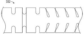
- A61B2017/00305—Constructional details of the flexible means
- A61B2017/00309—Cut-outs or slits
-
- A—HUMAN NECESSITIES
- A61—MEDICAL OR VETERINARY SCIENCE; HYGIENE
- A61B—DIAGNOSIS; SURGERY; IDENTIFICATION
- A61B17/00—Surgical instruments, devices or methods, e.g. tourniquets
- A61B17/00234—Surgical instruments, devices or methods, e.g. tourniquets for minimally invasive surgery
- A61B2017/00358—Snares for grasping
-
- A—HUMAN NECESSITIES
- A61—MEDICAL OR VETERINARY SCIENCE; HYGIENE
- A61B—DIAGNOSIS; SURGERY; IDENTIFICATION
- A61B17/00—Surgical instruments, devices or methods, e.g. tourniquets
- A61B17/04—Surgical instruments, devices or methods, e.g. tourniquets for suturing wounds; Holders or packages for needles or suture materials
- A61B17/0401—Suture anchors, buttons or pledgets, i.e. means for attaching sutures to bone, cartilage or soft tissue; Instruments for applying or removing suture anchors
- A61B2017/0406—Pledgets
-
- A—HUMAN NECESSITIES
- A61—MEDICAL OR VETERINARY SCIENCE; HYGIENE
- A61B—DIAGNOSIS; SURGERY; IDENTIFICATION
- A61B17/00—Surgical instruments, devices or methods, e.g. tourniquets
- A61B17/04—Surgical instruments, devices or methods, e.g. tourniquets for suturing wounds; Holders or packages for needles or suture materials
- A61B17/0401—Suture anchors, buttons or pledgets, i.e. means for attaching sutures to bone, cartilage or soft tissue; Instruments for applying or removing suture anchors
- A61B2017/0409—Instruments for applying suture anchors
-
- A—HUMAN NECESSITIES
- A61—MEDICAL OR VETERINARY SCIENCE; HYGIENE
- A61B—DIAGNOSIS; SURGERY; IDENTIFICATION
- A61B17/00—Surgical instruments, devices or methods, e.g. tourniquets
- A61B17/04—Surgical instruments, devices or methods, e.g. tourniquets for suturing wounds; Holders or packages for needles or suture materials
- A61B17/0401—Suture anchors, buttons or pledgets, i.e. means for attaching sutures to bone, cartilage or soft tissue; Instruments for applying or removing suture anchors
- A61B2017/0414—Suture anchors, buttons or pledgets, i.e. means for attaching sutures to bone, cartilage or soft tissue; Instruments for applying or removing suture anchors having a suture-receiving opening, e.g. lateral opening
-
- A—HUMAN NECESSITIES
- A61—MEDICAL OR VETERINARY SCIENCE; HYGIENE
- A61B—DIAGNOSIS; SURGERY; IDENTIFICATION
- A61B17/00—Surgical instruments, devices or methods, e.g. tourniquets
- A61B17/04—Surgical instruments, devices or methods, e.g. tourniquets for suturing wounds; Holders or packages for needles or suture materials
- A61B17/0401—Suture anchors, buttons or pledgets, i.e. means for attaching sutures to bone, cartilage or soft tissue; Instruments for applying or removing suture anchors
- A61B2017/0417—T-fasteners
-
- A—HUMAN NECESSITIES
- A61—MEDICAL OR VETERINARY SCIENCE; HYGIENE
- A61B—DIAGNOSIS; SURGERY; IDENTIFICATION
- A61B17/00—Surgical instruments, devices or methods, e.g. tourniquets
- A61B17/04—Surgical instruments, devices or methods, e.g. tourniquets for suturing wounds; Holders or packages for needles or suture materials
- A61B17/0401—Suture anchors, buttons or pledgets, i.e. means for attaching sutures to bone, cartilage or soft tissue; Instruments for applying or removing suture anchors
- A61B2017/0419—H-fasteners
-
- A—HUMAN NECESSITIES
- A61—MEDICAL OR VETERINARY SCIENCE; HYGIENE
- A61B—DIAGNOSIS; SURGERY; IDENTIFICATION
- A61B17/00—Surgical instruments, devices or methods, e.g. tourniquets
- A61B17/04—Surgical instruments, devices or methods, e.g. tourniquets for suturing wounds; Holders or packages for needles or suture materials
- A61B17/0401—Suture anchors, buttons or pledgets, i.e. means for attaching sutures to bone, cartilage or soft tissue; Instruments for applying or removing suture anchors
- A61B2017/044—Suture anchors, buttons or pledgets, i.e. means for attaching sutures to bone, cartilage or soft tissue; Instruments for applying or removing suture anchors with a threaded shaft, e.g. screws
- A61B2017/0441—Suture anchors, buttons or pledgets, i.e. means for attaching sutures to bone, cartilage or soft tissue; Instruments for applying or removing suture anchors with a threaded shaft, e.g. screws the shaft being a rigid coil or spiral
-
- A—HUMAN NECESSITIES
- A61—MEDICAL OR VETERINARY SCIENCE; HYGIENE
- A61B—DIAGNOSIS; SURGERY; IDENTIFICATION
- A61B17/00—Surgical instruments, devices or methods, e.g. tourniquets
- A61B17/04—Surgical instruments, devices or methods, e.g. tourniquets for suturing wounds; Holders or packages for needles or suture materials
- A61B17/0401—Suture anchors, buttons or pledgets, i.e. means for attaching sutures to bone, cartilage or soft tissue; Instruments for applying or removing suture anchors
- A61B2017/0464—Suture anchors, buttons or pledgets, i.e. means for attaching sutures to bone, cartilage or soft tissue; Instruments for applying or removing suture anchors for soft tissue
-
- A—HUMAN NECESSITIES
- A61—MEDICAL OR VETERINARY SCIENCE; HYGIENE
- A61B—DIAGNOSIS; SURGERY; IDENTIFICATION
- A61B17/00—Surgical instruments, devices or methods, e.g. tourniquets
- A61B17/04—Surgical instruments, devices or methods, e.g. tourniquets for suturing wounds; Holders or packages for needles or suture materials
- A61B17/0487—Suture clamps, clips or locks, e.g. for replacing suture knots; Instruments for applying or removing suture clamps, clips or locks
- A61B2017/0488—Instruments for applying suture clamps, clips or locks
-
- A—HUMAN NECESSITIES
- A61—MEDICAL OR VETERINARY SCIENCE; HYGIENE
- A61B—DIAGNOSIS; SURGERY; IDENTIFICATION
- A61B17/00—Surgical instruments, devices or methods, e.g. tourniquets
- A61B17/04—Surgical instruments, devices or methods, e.g. tourniquets for suturing wounds; Holders or packages for needles or suture materials
- A61B2017/0496—Surgical instruments, devices or methods, e.g. tourniquets for suturing wounds; Holders or packages for needles or suture materials for tensioning sutures
-
- A—HUMAN NECESSITIES
- A61—MEDICAL OR VETERINARY SCIENCE; HYGIENE
- A61B—DIAGNOSIS; SURGERY; IDENTIFICATION
- A61B17/00—Surgical instruments, devices or methods, e.g. tourniquets
- A61B17/04—Surgical instruments, devices or methods, e.g. tourniquets for suturing wounds; Holders or packages for needles or suture materials
- A61B17/06—Needles ; Sutures; Needle-suture combinations; Holders or packages for needles or suture materials
- A61B2017/06052—Needle-suture combinations in which a suture is extending inside a hollow tubular needle, e.g. over the entire length of the needle
-
- A—HUMAN NECESSITIES
- A61—MEDICAL OR VETERINARY SCIENCE; HYGIENE
- A61B—DIAGNOSIS; SURGERY; IDENTIFICATION
- A61B18/00—Surgical instruments, devices or methods for transferring non-mechanical forms of energy to or from the body
- A61B2018/00315—Surgical instruments, devices or methods for transferring non-mechanical forms of energy to or from the body for treatment of particular body parts
- A61B2018/00345—Vascular system
- A61B2018/00351—Heart
- A61B2018/00369—Heart valves
-
- A—HUMAN NECESSITIES
- A61—MEDICAL OR VETERINARY SCIENCE; HYGIENE
- A61B—DIAGNOSIS; SURGERY; IDENTIFICATION
- A61B18/00—Surgical instruments, devices or methods for transferring non-mechanical forms of energy to or from the body
- A61B18/02—Surgical instruments, devices or methods for transferring non-mechanical forms of energy to or from the body by cooling, e.g. cryogenic techniques
- A61B2018/0212—Surgical instruments, devices or methods for transferring non-mechanical forms of energy to or from the body by cooling, e.g. cryogenic techniques using an instrument inserted into a body lumen, e.g. catheter
-
- A—HUMAN NECESSITIES
- A61—MEDICAL OR VETERINARY SCIENCE; HYGIENE
- A61F—FILTERS IMPLANTABLE INTO BLOOD VESSELS; PROSTHESES; DEVICES PROVIDING PATENCY TO, OR PREVENTING COLLAPSING OF, TUBULAR STRUCTURES OF THE BODY, e.g. STENTS; ORTHOPAEDIC, NURSING OR CONTRACEPTIVE DEVICES; FOMENTATION; TREATMENT OR PROTECTION OF EYES OR EARS; BANDAGES, DRESSINGS OR ABSORBENT PADS; FIRST-AID KITS
- A61F2220/00—Fixations or connections for prostheses classified in groups A61F2/00 - A61F2/26 or A61F2/82 or A61F9/00 or A61F11/00 or subgroups thereof
- A61F2220/0008—Fixation appliances for connecting prostheses to the body
- A61F2220/0016—Fixation appliances for connecting prostheses to the body with sharp anchoring protrusions, e.g. barbs, pins, spikes
Landscapes
- Health & Medical Sciences (AREA)
- Life Sciences & Earth Sciences (AREA)
- Cardiology (AREA)
- Engineering & Computer Science (AREA)
- Biomedical Technology (AREA)
- Surgery (AREA)
- General Health & Medical Sciences (AREA)
- Public Health (AREA)
- Heart & Thoracic Surgery (AREA)
- Animal Behavior & Ethology (AREA)
- Veterinary Medicine (AREA)
- Molecular Biology (AREA)
- Nuclear Medicine, Radiotherapy & Molecular Imaging (AREA)
- Medical Informatics (AREA)
- Transplantation (AREA)
- Oral & Maxillofacial Surgery (AREA)
- Vascular Medicine (AREA)
- Rheumatology (AREA)
- Prostheses (AREA)
- Surgical Instruments (AREA)
- Saccharide Compounds (AREA)
Abstract
혈관을 가로질러 인공 건삭을 식립하기 위한 경-혈관 인공 건삭 식립 방법 및 장치가 제공된다. 카테터는 좌심방 내부로, 승모판을 통해서, 그리고 좌심실 내부로 전진된다. 심실 앵커는 카테터로부터 좌심실 벽으로 전개되어, 상기 심실 앵커에 부착되고 상기 카테터를 통해 근위 방향으로 연장되는 심실 봉합사를 남겨두게 된다. 판엽 봉합사가 상기 카테터를 통해 근위 방향으로 연장된 상태에서, 판엽 앵커가 전개되어 승모판엽을 상기 판엽 봉합사에 고정하게 된다. 상기 판엽 봉합사는 상기 심실 봉합사에 고정되어, 상기 좌심방의 방향으로의 판엽 움직임 영역을 제한하게 된다. 또한, 새로운 유두근과 새로운 건삭을 구비하며, 체내의 원위치에서 조립되는 승모판엽 구속 장치가 제공된다.A light-vascular artificial bayonet placement method and apparatus for implanting artificial bayonet across a blood vessel is provided. The catheter is advanced into the left atrium, through the mitral valve, and into the left ventricle. The ventricular anchor develops from the catheter to the left ventricular wall, leaving a ventricular suture attached to the ventricular anchor and extending proximally through the catheter. In the state where the leaf leaf suture extends proximally through the catheter, the leaf leaf anchor is developed to fix the mitral leaf leaf to the leaf leaf suture. The leaflet suture is fixed to the ventricular suture, thereby limiting the region of leaflet movement in the direction of the left atrium. In addition, there is provided a mitral lobe restraint device having a new papillary muscle and a new tendon, and assembled in situ in the body.
Description
[우선권주장의 기초가 되는 선출원의 원용][Application of the first application on which the priority claim is based]
본 출원은 2017. 6. 29. 제출된 미국특허출원 15/638,176호의 일부계속출원으로서, 위 출원은 2016. 12. 30. 제출된 미국가특허출원 62/441,031호를 기초로 한 우선권을 주장한 바 있는데, 이들 출원 각각의 전체 내용을 모든 목적을 위해 원용하는 바이다.This application is a partial application of US Patent Application No. 15 / 638,176 filed on June 29, 2017. The above application claims priority based on US Patent Application No. 62 / 441,031 filed on December 30, 2016. The entire contents of each of these applications are hereby incorporated for all purposes.
본 출원은 승모판 재건 장치 및 기법에 관한 것으로서, 보다 상세하게는, 승모판폐쇄부전증을 완화시키기 위한 경혈관적(transvascular) 건삭 치환 방법 및 장치에 관한 것이다.TECHNICAL FIELD This application relates to mitral valve reconstruction devices and techniques, and more particularly, to a method and a device for transvascular dichroic replacement for alleviating mitral regurgitation.
심장은 4 개의 심장 판막을 구비하며, 이들 판막은 혈액이 심장의 4 개의 방실을 일방향으로 통과할 수 있게 해준다. 상기 4 개의 판막은 삼첨판, 승모판, 폐동맥판, 및 대동맥판이다. 상기 4 개의 방실은 좌우 심방(위쪽 방실) 및 좌우 심실(아래쪽 방실)이다.The heart has four heart valves, which allow blood to pass in one direction through the four chambers of the heart. The four valves are tricuspid valve, mitral valve, pulmonary artery valve, and aortic valve. The four atriums are the left and right atrium (upper chamber) and the left and right ventricles (lower chamber).
승모판은 전엽과 후엽으로 알려진 2 개의 판엽으로 구성되며, 이들 판엽은 심장의 펌핑 작용에 의해 판엽에 가해지는 압력에 응답하여 개폐된다. 승모판과 관련하여 진행되거나 발생할 수 있는 문제들이 몇 가지 있다. 이들 문제 중 하나로 승모판폐쇄부전증(MR: mitral valve regurgitation)이 있는데, 이는 승모판의 판엽들이 제대로 닫히지 않아서 승모판에서 누출을 일으킬 수 있게 되는 것이다. 심각한 승모판폐쇄부전증은 심장 기능에 악영향을 미쳐서, 환자의 삶의 질을 악화시키거나 수명을 단축시킬 수 있다.The mitral valve consists of two leaflets known as anterior lobe and posterior lobe, which are opened and closed in response to the pressure exerted on the leaflet by the pumping action of the heart. There are several issues that can occur or occur with the mitral valve. One of these problems is mitral valve regurgitation (MR), which can cause the valves of the mitral valve to close properly and cause leakage from the mitral valve. Severe mitral regurgitation can adversely affect cardiac function, which can worsen the quality of life or shorten the life of the patient.
승모판폐쇄부전증을 개선하기 위한 기법으로 여러 가지가 개발된 바 있다. 이들 기법들은, 환자의 단계나 병인에 따라, 심장 이식, 승모판 치환술, 건삭의 단축 내지 치환술, 그리고 판륜성형술(annuloplasty)라고도 알려져 있는 승모판환상재건술(mitral annular repair)을 포함한다.Several techniques have been developed to improve mitral regurgitation. These techniques include heart transplantation, mitral valve replacement, shortening or replacement of the abdomen, and mitral annular repair, also known as annuloplasty, depending on the stage or etiology of the patient.
건삭 치환 내지 재건과 관련하여, 수술적 접근법과 심첨을 경유하는(trans-apical) 접근법이 몇가지 제안된 바 있다. 그렇지만, 이러한 노력에도 불구하고, 승모판폐쇄부전증(MR)을 감소시키거나 제거할 수 있게 해주는 건삭 치환 내지 재건을 위한 경혈관적(transvascular) 접근법에 대한 니즈가 여전히 존재하는 형편이다.Regarding palliative replacement or reconstruction, several surgical and trans-apical approaches have been proposed. Nevertheless, despite these efforts, there is still a need for a transvascular approach for pruning replacement or reconstruction that allows to reduce or eliminate mitral regurgitation (MR).
본 발명의 일 양태에 따르면, 혈관을 가로질러 인공 건삭을 식립하는 경-혈관 인공 건삭 식립 방법이 제공된다. 상기 방법은 좌심방 내부로, 승모판을 통해서, 그리고 좌심실 내부로 카테터를 전진시키는 단계;와, 상기 카테터로부터 상기 좌심실의 벽으로 심실 앵커를 전개하여, 상기 심실 앵커에 부착되고 상기 카테터를 통해 근위 방향으로 연장되는 심실 봉합사를 남겨두는 단계;를 포함한다. 판엽 봉합사가 상기 카테터를 통해 근위 방향으로 연장된 상태에서, 판엽 앵커가 전개되어 승모판엽을 상기 판엽 봉합사에 고정하게 된다. 상기 판엽 봉합사는 상기 심실 봉합사에 고정되어, 상기 좌심방의 방향으로의 판엽 움직임 영역을 제한하게 된다.According to one aspect of the present invention, there is provided a light-vascular artificial bayonet implantation method for implanting artificial bayonet across a blood vessel. The method includes advancing a catheter into the left atrium, through the mitral valve, and into the left ventricle; and deploying a ventricular anchor from the catheter to the wall of the left ventricle, attached to the ventricular anchor and proximal through the catheter. Leaving an extended ventricular suture. In the state where the leaf leaf suture extends proximally through the catheter, the leaf leaf anchor is developed to fix the mitral leaf leaf to the leaf leaf suture. The leaflet suture is fixed to the ventricular suture, thereby limiting the region of leaflet movement in the direction of the left atrium.
상기 판엽 앵커를 전진시키는 단계는 상기 판엽 앵커를 상기 판엽에서 판엽 맞물림 모서리로부터 약 3 ㎜ 내지 약 10 ㎜인 영역 내에 고정시키는 것을 포함할 수 있다. 상기 심실 앵커를 전개하는 단계는 상기 앵커를 심첨으로부터 바람직하게 이격되어 있는 심실 중격이나 심실 벽에 부착하는 것을 포함할 수 있다. 상기 심실 앵커를 전개하는 단계는 상기 승모판을 통해 앵커 드라이버를 전진시키고, 상기 앵커 드라이버를 회전시켜서 상기 심실 앵커를 고정시키고, 상기 앵커 드라이버를 근위 방향으로 후퇴시켜서 상기 심실 앵커에 의해 운반되는 상기 심실 봉합사가 노출되게 하는 것을 포함할 수 있다.Advancing the leaflet anchor may comprise securing the leaflet anchor in an area of about 3 mm to about 10 mm from the leaf engaging edge in the leaflet. Deploying the ventricular anchor may include attaching the anchor to a ventricular septum or ventricular wall that is preferably spaced from the apical. Deploying the ventricular anchor includes advancing an anchor driver through the mitral valve, rotating the anchor driver to secure the ventricular anchor, and retracting the anchor driver in the proximal direction to be carried by the ventricular anchor. May be exposed.
판엽 앵커를 전개하는 단계는 바늘 가이드를 상기 판엽에 접촉하도록 배치하고 상기 바늘을 상기 바늘 가이드로부터 상기 판엽을 통해서 전진시키는 것을 포함할 수 있다. 상기 방법은 상기 바늘 가이드의 원위 단부를 적어도 약 160 도의 각도만큼 굴절시켜서 상기 바늘 가이드의 원위 단부가 상기 판엽의 상기 심실 측에 대항하여 위치되게 하는 것을 더 포함할 수 있다. 상기 바늘 가이드는 슬롯이 형성된 튜브를 포함할 수 있고, 상기 바늘 가이드를 굴절시키는 것은 당김 줄을 근위 방향으로 후퇴시킴으로써 달성될 수 있다.Deploying the leaflet anchors may include placing a needle guide in contact with the leaflet and advancing the needle from the needle guide through the leaflet. The method may further comprise refracting the distal end of the needle guide at an angle of at least about 160 degrees such that the distal end of the needle guide is positioned against the ventricular side of the leaflet. The needle guide may comprise a slotted tube and the deflection of the needle guide may be accomplished by retracting the pull string in the proximal direction.
상기 판엽 봉합사를 고정시키는 단계는 상기 심실 봉합사 및 상기 판엽 봉합사에 봉합사 로크를 적용하는 것을 포함할 수 있다. 상기 방법은 상기 판엽 봉합사를 고정시키는 단계 이전에, 판엽 기능을 향상시키기 위하여 상기 판엽 봉합사에 장력을 가하는 단계;를 더 포함할 수 있다. 상기 방법은 수축기 동안의 판엽 움직임 한계를 대략 판륜의 레벨로 끌어당기기 위해 판엽 봉합사에 충분한 장력을 가하는 단계;를 더 포함할 수 있다. 상기 판엽 봉합사를 고정시키는 단계는 상기 판엽 봉합사와 상기 심실 봉합사를 고정하기 위한 매듭을 짓는 것을 포함할 수 있다. 상기 방법은 상기 매듭 가까이에서 상기 판엽 봉합사 및 상기 심실 봉합사를 절단하여, 상기 상기 판엽 봉합사 및 상기 심실 봉합사가 선천적 건삭으로서 기능하게 남게두는 단계;를 더 포함할 수 있다.Fixing the leaf suture may include applying a suture lock to the ventricular suture and the leaf suture. The method may further include applying a tension to the leaf suture to improve the leaf function before the step of fixing the leaf suture. The method may further comprise applying sufficient tension to the leaf sutures to pull the leaf motion limits during the systolic to approximately the level of the annulus. The fixing of the leaf suture may include forming a knot for fixing the leaf suture and the ventricular suture. The method may further include cutting the leaflet suture and the ventricular suture near the knot, leaving the leaflet suture and the ventricular suture to function as congenital dry.
상기 방법은 다음 그룹 즉, 환자가 1차 내지 퇴행성 승모판폐쇄부전 진단을 받음; 환자가 2차 내지 기능성 승모판폐쇄부전 진단을 받음; 환자가 점액성 승모판폐쇄부전 진단을 받음; 환자가 동요판엽, 건삭 파열, 판엽탈출증 진단을 받음; 환자가 1등급 또는 그 이상의 승모판폐쇄부전을 앓고 있음; 환자의 A2 판엽에서 P2 판엽까지의 판륜 직경이 최소 5 ㎜이고 P2 및 A2 판엽의 길이의 합(P2 + A2) 미만임; 환자가 최소 10 ㎜의 A2에서 P2까지 판륜 직경을 가짐; 및 환자가 최소 2 ㎜의 액세스 베슬 직경을 가짐;에서 선택되는 적어도 세 가지 특성을 가진 환자를 식별하는 초기 단계;를 더 포함할 수 있다.The method comprises the following groups, that is, patients are diagnosed with primary to degenerative mitral regurgitation; The patient is diagnosed with secondary to functional mitral regurgitation; The patient is diagnosed with mucus mitral regurgitation; The patient is diagnosed with agitated leaflets, cleft tears, and leaflet escape; The patient has
환자는 추가적으로 다음 그룹 즉, 환자가 최소 1 명의 심장외과의를 포함하는 심장팀이 평가하여 기존의 개흉수술을 받을 적절한 후보가 아닌 것으로 결정됨; 환자가 2 또는 그 이상의 STS 예측방식 수술사망률(STS 스코어)을 가짐; 환자가 개흉수술을 제시받고 거절했음; 환자의 연령이 18~90 세임; 환자가 수혈을 거부함; 환자가 이전의 개흉수술 경험이 있음; 및 환자가 적어도 10~60 %의 박출율을 가짐;에서 선택되는 적어도 하나의 특징을 추가적으로 가질 수 있다.The patient is additionally assessed by the next group, a cardiac team in which the patient includes at least one cardiac surgeon, to determine that he is not a suitable candidate for conventional thoracotomy; The patient has two or more STS predictive mortality rates (STS scores); The patient was presented with and refused thoracotomy; The age of the patient is between 18 and 90 years old; The patient refuses a blood transfusion; The patient has had previous thoracotomy; And at least 10-60% ejection rate of the patient.
본 발명의 추가적인 양태에 따르면, 수축기 동안의 승모판엽 맞물림 영역을 증대하는 방법이 제공된다. 상기 방법은 적어도 제1 심실 장력 요소를 상기 심실의 벽에 고정하는 단계;와 적어도 제1 판엽 장력 요소를 승모판엽에 고정하는 단계;를 포함한다. 상기 판엽 장력 요소는 근위 방향으로 후퇴되어, 수축기 동안의 판엽 움직임 한계를 상기 심실 방향으로 이동시키고 이를 통해 수축기 동안의 승모판엽 맞물림 영역을 증가시킨다. 그 다음, 상기 판엽 장력 요소는 상기 심실 장력 요소에 고정된다.According to a further aspect of the invention, a method of augmenting the mitral lobe engagement area during systolic is provided. The method includes securing at least a first ventricular tension element to the wall of the ventricle and securing at least a first leaflet tension element to the mitral valve leaf. The leaflet tension element is retracted in the proximal direction, shifting the leaflet movement limit during the systole to the ventricular direction, thereby increasing the mitral leaf engaging region during the systole. The leaflet tension element is then secured to the ventricular tension element.
상기 심실 장력 요소는 상기 심실 앵커를 대향하는 원위 단부와 선천적 유두근의 대략 상단 높이에 있는 근위 단부를 구비하는 새로운 유두근을 포함할 수 있고, 상기 판엽 장력 요소를 고정하는 단계는 상기 새로운 유두근의 상기 근위 단부에서 상기 판엽 장력 요소를 상기 심실 장력 요소에 고정하는 것을 포함할 수 있다. 상기 상기 새로운 유두근은 확장형 폴리테트라플루오로에틸렌(ePTFE)을 포함할 수 있다.The ventricular tension element may comprise a new papilla with a distal end opposite the ventricular anchor and a proximal end at approximately the top height of the congenital papilloma, and the securing of the leaflet tension element may comprise the proximal end of the new papillary muscle. Securing at the end the leaflet tension element to the ventricular tension element. The new papillary muscle may comprise expanded polytetrafluoroethylene (ePTFE).
상기 카테터로 상기 판엽 장력 요소를 고정하는 단계는 원위 단부를 구비하는 바늘 가이드를 상기 승모판을 통해서 좌심실 내부로 전진시키는 단계; 및 상기 바늘 가이드를 적어도 약 160 도의 각도만큼 굴절시켜서 상기 원위 단부를 이완기 동안에 상기 판엽에 접촉하도록 위치시키는 단계;를 포함할 수 있다. 상기 방법은 판엽 앵커 전개 바늘을 상기 바늘 가이드의 상기 원위 단부로부터 상기 판엽을 통해 전진시키고, 상기 바늘로부터 상기 앵커를 전개하는 단계;를 더 포함할 수 있다. 상기 앵커를 전개하는 단계는 상기 전개 바늘 내에서의 축소된 단면인 제1 단면으로부터 판엽의 심방 측에 대항하여 안착되는 확대된 단면인 제2 단면으로 앵커를 전개하는 것을 포함할 수 있다. 상기 앵커를 전개하는 단계는 거어즈를 전개하는 것을 포함할 수 있다.Fixing the leaflet tension element with the catheter includes advancing a needle guide having a distal end through the mitral valve into the left ventricle; And deflecting the needle guide at an angle of at least about 160 degrees to position the distal end to contact the leaflet during the diastolic phase. The method may further include advancing a leaflet anchoring needle through the leaflet from the distal end of the needle guide and deploying the anchor from the needle. Deploying the anchor may include deploying the anchor from a first cross section, which is a reduced cross section in the deployment needle, to a second cross section, an enlarged cross section seated against the atrial side of the leaf leaf. Deploying the anchor can include deploying a gauze.
상기 판엽 장력 요소를 근위 방향으로 후퇴시키는 단계는 적어도 개구를 통해 연장되는 상기 판엽 장력 요소로 상기 좌심실에 상기 개구를 위치시키는 단계; 및 상기 장력 요소가 상기 심실 방향으로 상기 판엽을 당길 수 있도록, 상기 개구를 지렛목으로 하여 상기 판엽 장력 요소를 근위 방향으로 후퇴시키는 단계;를 포함할 수 있다. 상기 지렛목은 상기 카테터의 말단 개구일 수 있고, 상기 판엽 장력 요소를 근위 방향으로 후퇴시시키는 단계는 상기 카테터를 통해 상기 판엽 장력 요소를 근위 방향으로 후퇴시키는 것을 포함할 수 있다. 상기 방법은 제2 판엽 장력 요소를 상기 판엽과 상기 심실 장력 요소에 고정하는 단계;를 더 포함할 수 있다.Retracting the leaf tension element proximally includes positioning the opening in the left ventricle with the leaf tension element extending at least through the opening; And retracting the leaflet tension element in the proximal direction with the opening as a lever so that the tension element pulls the leaflet in the ventricular direction. The lever may be a distal opening of the catheter, and retracting the leaflet tension element in the proximal direction may include retracting the leaflet tension element proximally through the catheter. The method may further comprise securing a second leaflet tension element to the leaflet and the ventricular tension element.
본 발명의 추가적인 양태에 따르면, 체내의 원위치에서 조립되는 승모판엽 구속 장치가 제공된다. 상기 구속 장치는 근위 단부와 원위 단부를 구비하고, 가늘고 길며 유연성을 가진 새로운 유두근;과 상기 새로운 유두근의 원위 단부에 부착되는 나선형 조직 앵커;를 구비한다. 가늘고 길며 유연성을 가진 인공 건삭은 상기 새로운 유두근으로부터 근위 방향으로 연장되며, 판엽 앵커는 상기 인공 건삭의 근위 단부에 부착된다. 상기 판엽 앵커는 상기 카테터를 통해 전진시키기 위한 제1의 축소된 단면으로부터 상기 판엽의 심방측에 접촉하기 위한 제2의 확장된 단면으로 확장가능하다. 상기 인공 건삭은 상기 새로운 유두근을 통해서 나선형 조직 앵커에 원위 방향으로 연장되는 봉합사에 부착될 수 있다.According to a further aspect of the present invention, there is provided a mitral valve restraint device that is assembled in situ in the body. The restraint device has a proximal end and a distal end, a thin, long and flexible new papilla; and a spiral tissue anchor attached to the distal end of the new papilla. An elongated and flexible artificial tendon extends proximally from the new papillary muscle and a leaflet anchor is attached to the proximal end of the artificial tendon. The leaflet anchor is expandable from a first reduced cross section for advancing through the catheter to a second extended cross section for contacting the atrial side of the leaf leaf. The artificial tendon may be attached to a suture extending distal to the helical tissue anchor through the new papillary muscle.
상기 나선형 조직 앵커는 레이저 절삭 하이포튜브를 구비할 수 있다. 상기 나선형 조직 앵커는 하나 또는 두 개 이상의 코일형 곡선 와이어를 구비할 수 있다.상기 인공 건삭은 상기 새로운 유두근의 근위 단부에서 상기 판엽 앵커로 연장되는 봉합사를 포함할 수 있다. 상기 봉합사는 상기 새로운 유두근을 통해 상기 나선형 조직 앵커로 연장될 수 있다.The spiral tissue anchor may have a laser cutting hypotube. The helical tissue anchor may have one or more coiled curved wires. The artificial tendon may include a suture extending from the proximal end of the new papillary to the leaflet anchor. The suture may extend through the new papillary to the helical tissue anchor.
상기 인공 건삭은 상기 새로운 유두근으로부터 근위 방향으로 연장되는 제1 컴포넌트와, 상기 판엽 앵커로부터 원위 방향으로 연장되는 제2 컴포넌트를 포함할 수 있다. 상기 제1 컴포넌트의 근위 부분과, 상기 제2 컴포넌트의 원위 부분은 록킹 장치에 의해 함께 결합될 수 있다. 상기 록킹 장치가 잠긴 상태의 구성과 잠금해제된 상태의 구성을 구비할 수 있다. 상기 록킹 장치는 잠금해제 상태의 구성에 있을 때 상기 제1 컴포넌트 및 상기 제2 컴포넌트 상으로 전진하고, 잠금 상태의 구성에 있을 때 상기 제1 컴포넌트 및 상기 제2 컴포넌트를 고정적으로 클램핑할 수 있다.The artificial tendon may comprise a first component extending proximally from the new papillary muscle and a second component extending distally from the leaf leaf anchor. The proximal portion of the first component and the distal portion of the second component can be joined together by a locking device. The locking device may have a configuration in a locked state and a configuration in an unlocked state. The locking device may advance on the first component and the second component when in the unlocked configuration, and may clamp the first component and the second component fixedly when in the locked configuration.
상기 판엽 앵커는 거어즈를 구비할 수 있다. 상기 거어즈는 상기 거어즈에 결합된 봉합사를 당김으로써 붕괴되도록 구성될 수 있고, 붕괴되었을 때 상기 제2의 확장된 단면을 취할 수 있다. 상기 봉합사는 상기 거어즈에 있는 적어도 두 개, 적어도 세 개, 또는 세 개 이상의 개구들에 끼워지게 될 수 있다. 상기 개구들은 동일 직선 상에 있을 수 있다. 상기 상기 판엽 앵커는 T-태그 바를 구비할 수 있다. 상기 T-태그 바는 봉합사에 회동가능하게 결합된 바를 구비할 수 있고, 상기 바의 회전은 상기 판엽 앵커를 상기 제1의 축소된 단면으로부터 상기 제2의 확장된 단면으로 확장시킬 수 있다. 상기 판엽 앵커는 허브를 구비할 수 있다. 상기 허브는 반지름 방향으로 연장되는 복수의 가요성 스포크들을 구비할 수 있다. 상기 스포크들은 전달 바늘 안에 갇혀있도록 휘어져서 길이방향 축을 따라 정렬되고, 갇혀있지 않게 되었을 때 반지름방향 외측으로 확장되어 상기 제1의 축소된 단면으로부터 상기 제2의 확장된 단면으로 상기 판엽 앵커를 확장시킬 수 있다.The leaflet anchor may have a gauze. The gauze may be configured to collapse by pulling the suture coupled to the gauze and may take the second expanded cross section when collapsed. The suture may be fitted into at least two, at least three, or three or more openings in the gauze. The openings may be on the same straight line. The leaflet anchor may have a T-tag bar. The T-tag bar may have a bar pivotally coupled to the suture, and rotation of the bar may extend the leaflet anchor from the first reduced cross section to the second expanded cross section. The leaflet anchor may have a hub. The hub may have a plurality of flexible spokes extending in the radial direction. The spokes are flexed to be confined within the transfer needle so that they are aligned along the longitudinal axis and when radially unbound, extend the radially outward to extend the leaflet anchor from the first reduced cross section to the second extended cross section. Can be.
상기 나선형 앵커는 상기 봉합사를 수용하고 마찰력에 의해 고정하도록 구성된 허브를 구비할 수 있다. 상기 나선형 앵커는 상기 새로운 유두근을 상기 나선형 앵커에 고정시키는 루프를 구비할 수 있다. 상기 새로운 유두근은 부드러운 리본을 구비할 수 있다.The helical anchor may have a hub configured to receive the suture and secure by friction. The helical anchor may have a loop that secures the new papillary to the helical anchor. The new papillary muscle may have a soft ribbon.
본 발명의 추가적인 양태에 따르면, 인공 건삭 전개 시스템은 길이가 길고 가요성이 있으며 근위 단부와 원위 단부를 구비하는 튜브형 바디를 구비한다. 나선형 심실 앵커는 상기 튜브형 바디 내에 위치하고, 상기 튜브형 바디를 통해 근위 방향으로 연장된다. 판엽 앵커는 상기 카테터 내에 위치하고, 상기 튜브형 바디를 통해 근위 방향으로 연장되는 봉합사를 구비한다.According to a further aspect of the present invention, the artificial dry deployment system has a tubular body that is long and flexible and has a proximal end and a distal end. A helical ventricular anchor is located within the tubular body and extends proximally through the tubular body. The leaflet anchor is positioned within the catheter and has a suture extending proximally through the tubular body.
본 발명의 추가적인 양태에 따르면, 인공 건삭 전개 시스템이 제공된다. 상기 전개 시스템은 근위 단부와 원위 단부를 구비하는 카테터; 상기 카테터 내에 있는 나선형 앵커; 및 상기 카테터 내에 있는 반지름방향으로 확장가능한 판엽 앵커;를 구비한다. 상기 나선형 앵커는 상기 나선형 앵커를 회전시킬 수 있게 구성되는 드라이버를 구비한다. 상기 판엽 앵커는 상기 카테터를 통해 근위 방향으로 연장되는 봉합사를 구비한다.According to a further aspect of the present invention, an artificial dry deployment system is provided. The deployment system includes a catheter having a proximal end and a distal end; A spiral anchor in the catheter; And a leaf expandable radially radially within the catheter. The helical anchor has a driver configured to rotate the helical anchor. The leaflet anchor has a suture extending in the proximal direction through the catheter.
상기 반지름방향으로 확장가능한 판엽 앵커는 거어즈를 구비할 수 있다. 상기 거어즈는 상기 봉합사의 근위 방향 수축에 의해 가늘고 긴 스트립 형태로부터 반지름방향으로 확장되고 축방향으로 단축된 형태로 변형될 수 있다. 상기 반지름방향으로 확장가능한 판엽 앵커는 두 장의 재료 시트 사이에 삽입되는 봉합사를 포함할 수 있다. 상기 반지름방향으로 확장가능한 판엽 앵커는 상기 카테터 내에서 운반되는 굴절가능한 전개 튜브를 구비할 수 있다.The radially expandable leaflet anchor may have gauze. The gauze may be deformed from the elongated strip form in the radial direction and shortened in the axial direction by the proximal contraction of the suture. The radially expandable leaflet anchor may comprise a suture inserted between two sheets of material. The radially expandable leaflet anchor may have a deflectable deployment tube carried in the catheter.
상기 전개 튜브의 말단 굴절영역은 근위의 굴절제어 장치의 조작에 응답하여 적어도 약 160 도의 각도만큼 굴절될 수 있다. 상기 말단 굴절영역은 상기 전개 튜브의 원위 단부로부터 약 1.5cm 이내에 있을 수 있다. 상기 말단 굴절영역은 굴절되어 약 1.5cm 이하의 최적맞춤 반경을 갖는 곡선을 형성할 수 있다. 상기 굴절가능한 전개 튜브는 슬롯형 굴절 튜브를 구비할 수 있다.The distal refraction region of the deployment tube may be refracted by at least about 160 degrees in response to manipulation of the proximal refraction control device. The distal deflection zone may be within about 1.5 cm from the distal end of the deployment tube. The terminal refracted region may be refracted to form a curve having an optimal fit radius of about 1.5 cm or less. The deflectable deployment tube may have a slotted refractory tube.
상기 인공 건삭 전개 시스템은 상기 나선형 앵커를 원위 방향으로 전개하도록, 그리고 상기 반지름방향으로 확장가능한 앵커를 근위 방향으로 전개하도록 구성될 수 있다. 상기 나선형 앵커와 상기 드라이버는 상기 카테터로부터 제거된 후에, 상기 확장가능한 판엽 앵커가 상기 카테터에 순차적으로 삽입될 수 있다. 상기 확장가능한 판엽 앵커, 상기 나선형 앵커, 및 상기 드라이버는 상기 카테터 내에 사전적재될 수 있다.The artificial drought deployment system may be configured to deploy the helical anchor in the distal direction and to deploy the radially expandable anchor in the proximal direction. After the helical anchor and the driver are removed from the catheter, the expandable leaflet anchor may be inserted into the catheter sequentially. The expandable leaflet anchor, the helical anchor, and the driver may be preloaded in the catheter.
본 발명의 추가적인 양태에 따르면, 판엽 앵커 전달 시스템이 제공된다. 상기 판엽 앵커 전달 시스템은 전달 샤프트와 조직 천공 요소를 구비한다. 상기 전달 샤프트는 원위 부분과 근위 부분을 구비하고, 상기 원위 부분에 위치하는 굴절영역을 구비한다. 상기 조직 천공 요소는 상기 전달 샤프트의 원위 단부를 통해서 전진될 수 있게 구성된다. 상기 굴절영역은, 상기 전달 샤프트의 근위 단부가 좌심방 내부로 연장되는 상태에서 상기 전달 샤프트의 원위 단부를 판엽의 심실 측에 배치하도록, 구성된다. 상기 굴절영역은 굴절 튜브를 구비할 수 있다. 상기 굴절 튜브는 굴절되었을 때 약 2 ㎝ 미만의 최적의 곡률반경을 가질 수 있다.According to a further aspect of the invention, a leaflet anchor delivery system is provided. The leaflet delivery system has a delivery shaft and a tissue puncture element. The transmission shaft has a distal portion and a proximal portion and has a deflection zone located at the distal portion. The tissue puncture element is configured to be advanced through the distal end of the delivery shaft. The refractive zone is configured to place the distal end of the delivery shaft on the ventricular side of the leaf with the proximal end of the delivery shaft extending into the left atrium. The refractive region may have a refractive tube. The deflection tube may have an optimum radius of curvature of less than about 2 cm when refracted.
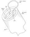
본 발명의 추가적인 양태에 따르면, 심장 판엽에 앵커고정(anchoring)하기 위한 거어즈가 제공된다. 상기 거어즈는 실질적으로 중첩하는 영역을 가지는 두 개의 편평한 시트들; 상기 두 개의 평평한 시트들 사이에 위치하는 봉합사; 및 상기 두 개의 편평한 시트들을 통해 연장되는 하나 이상의 개구;를 구비한다. 상기 봉합사는 근위 단부 및 원위 단부를 가진다. 상기 근위 단부는 상기 두 개의 편평한 시트들의 제1 측면으로부터 연장된다. 상기 하나 이상의 개구는 상기 봉합사를 수용할 수 있는 크기를 가진다. 상기 두 개의 편평한 시트들은 상기 봉합사의 양측에서 상기 중첩하는 영역의 일부 상에서 서로 결합되어 있다.According to a further aspect of the invention, a gauze is provided for anchoring the heart leaf. The gauze includes two flat sheets having a substantially overlapping area; A suture positioned between the two flat sheets; And one or more openings extending through the two flat sheets. The suture has a proximal end and a distal end. The proximal end extends from the first side of the two flat sheets. The one or more openings are sized to receive the suture. The two flat sheets are joined to each other on a portion of the overlapping area on both sides of the suture.
상기 봉합사는 상기 두 개의 시트들 사이에서 적어도 부분적으로 평탄화되어 있을 수 있다. 상기 하나 이상의 개구는 평탄화된 봉합사를 통해 연장될 수 있다. 상기 봉합사의 원위 단부는 상기 두 개의 편평한 시트들에서 상기 제1 측면의 반대편에 있는 제2 측면으로 연장될 수 있다. 상기 봉합사는 상기 두 개의 편평한 시트들 사이에서 실질적으로 직선을 따라 연장될 수 있다. 상기 봉합사는 상기 두 개의 편평한 시트들 사이에서 지그재그로 또는 믈결처럼 움직이는 방향으로 연장될 수 있다. 상기 두 개의 편평한 시트들은 확장형 폴리테트라플루오로에틸렌(ePTFE)을 포함할 수 있다. 상기 두 개의 편평한 시트들 중 적어도 하나는 부분적으로 소결되어 있을 수 있다.The suture may be at least partially planarized between the two sheets. The one or more openings may extend through the flattened suture. The distal end of the suture may extend from the two flat sheets to a second side opposite the first side. The suture may extend substantially along a straight line between the two flat sheets. The suture may extend in a zigzag or smoothly moving direction between the two flat sheets. The two flat sheets may comprise expanded polytetrafluoroethylene (ePTFE). At least one of the two flat sheets may be partially sintered.
상기 두 개의 편평한 시트들의 상기 제1 측면으로부터 연장되는 상기 봉합사의 근위 단부는 상기 하나 이상의 개구에 꿰어져 있을 수 있다. 상기 거어즈는 The proximal end of the suture extending from the first side of the two flat sheets may be sewn into the one or more openings. The gauze is
상기 두 개의 편평한 시트들이 적어도 한번 접혀져 있다가 반지름방향으로 확장된 단면을 형성하는 접혀진 구성을 구비할 수 있다. 상기 반지름방향으로 확장된 단면은 상기 하나 이상의 개구를 통해 통과하였을 때 상기 봉합사 주위로 연장될 수 있다.The two flat sheets can be folded at least once and have a folded configuration to form a radially expanded cross section. The radially extending cross section may extend around the suture when passed through the one or more openings.
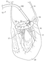
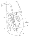
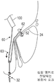
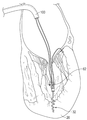
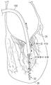
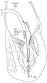
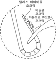
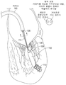
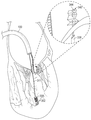
도 1은 카테터를 통해서 전달된 봉합사가 부착된 상태의 승모판륜를 보여준다.
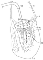
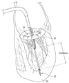
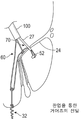
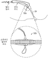
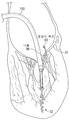
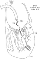
도 2는 카테터를 통해서 전달되고, 승모판륜에 접속된 봉합사에 부착되는 말단 앵커를 보여준다.
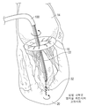
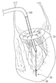
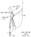
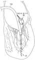
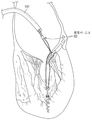
도 3은 추후에 승모판엽 또는 승모판륜에 부착할 수 있도록 봉합사 선들을 구비하며, 심장의 심첨에 회전에 의해 고정되는 말단 앵커를 보여준다.
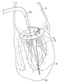
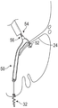
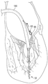
도 4는 승모판엽 또는 승모판륜에 부착된 봉합사 선들을 구비하며, 심장의 심첨에 회전에 의해 고정되는 말단 앵커를 보여준다.
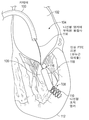
도 5는 심장의 심첨에 부착되고, 유두근의 상단과 대략 같은 높이가 되도록 심장의 심첨 위로 돌출되는 말단 앵커를 보여준다.
도 6은 심장의 심첨에 부착되고, 유두근의 상단과 대략 같은 높이가 되도록 심장의 심첨 위로 돌출되며, 승모판륜 및/또는 승모판엽에 부착된 말단 앵커를 보여준다.
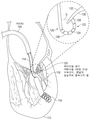
도 7은 심장의 심첨에 부착되고, 유두근의 상단과 대략 같은 높이가 되도록 심장의 심첨 위로 돌출되며, 카테터를 관통하여 가로지르는 루프 봉합사에 부착된 말단 앵커를 보여준다.
도 8은 승모판엽의 심실 측에 스트레인 릴리프가 마련된 승모판엽과, 좌심실의 저면에 있는 말단 앵커를 관통하며, 최종적인 봉합사 장력 조정이 봉합사 꼬리 위로 전진되어 있는 봉합사 로크로 유지되는 카테터-전달 봉합사 루프를 보여준다.
도 9는 승모판엽의 심실 측에 스트레인 릴리프가 마련된 승모판엽을 관통하는 카테터-전달 봉합사 선과, 봉합사를 절단하기 전에 봉합사 꼬리를 고정할 수 있도록 승모판엽의 심방 측으로 전진하는 봉합사 로크를 보여준다.
도 10은 승모판엽의 심실 측에 스트레인 릴리프가 마련된 승모판엽을 관통하는 카테터-전달 봉합사 선과, 봉합사 꼬리를 고정할 수 있도록 승모판엽의 심방 측으로 전진하는 봉합사 로크를 보여준다. 봉합사 꼬리의 타 단부는 카테터 핸들로부터 카테터를 통해 연장되어, 봉합사를 팽팽하게 할 수 있도록, 좌심실의 저부에 있는 말단 앵커 주위를 가로지르게 된다. 사용자에 의해 봉합사 장력이 조절되면, 제2 봉합사 로크는 최종적인 봉합사 꼬리 상에서 전진될 수 있다.
도 11은 승모판엽의 심실 측에 스트레인 릴리프가 마련된 승모판엽을 관통하고 스트레인 릴리프와 좌심실의 저부에 있는 말단 앵커를 거치는 루프 형태로 되어 있으며, 최종적인 봉합사 장력 조정이 봉합사 꼬리 위로 전진되어 있는 봉합사 로크로 유지되는 카테터-전달 봉합사 선을 보여준다. 판엽을 안정되게 붙잡고 스트레인 릴리프가 천공하는 힘에 대응하는 힘을 제공하는 것은 승모판에 접근되는 냉동 카테터를 사용하여 달성될 수 있다.
도 12는 승모판엽을 관통하고, 승모판엽의 심실 측에 전달되어야 할 스트레인 릴리프를 구비하며, 스트레인 릴리프와 좌심실의 저부에 있는 말단 앵커를 거치는 루프 형태로 되어 있고, 최종적인 봉합사 장력 조정이 봉합사 꼬리 위로 전진되어 있는 봉합사 로크로 유지되는 카테터-전달 봉합사 선을 보여준다. 판엽을 안정되게 붙잡고 스트레인 릴리프가 천공하는 힘에 대응하는 힘을 제공하는 것은 승모판에 접근되는 냉동 카테터에 의해 구현된다.
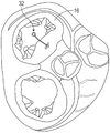
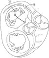
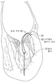
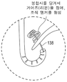
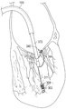
도 13은 일부 실시예에서 승모판륜이 관통되어 있고 말단 앵커가 선천적 유두근에 대하여 위치하도록 설치된 것을 심방 측에서 본 모습을 도시한 도면이다.
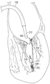
도 14는 일부 실시예에서 승모판륜이 관통되어 있고 말단 앵커가 선천적 유두근에 대하여 위치하도록 설치된 것을 심방 측에서 본 모습을 도시한 도면이다.
도 15는 좌심실의 심첨에 부착하기 위한 것으로서, 연결 지점을 유두근의 높이에 더 가깝게 하여 정확한 각도를 시뮬레이션하고 새로운 코드 연결에 정합되게 해주는 수직 융기부를 구비하는 다양한 앵커들을 보여주는데, 이 실시예들은 코일형 곡선 와이어와 레이저 절삭 하이포튜브를 포함한다.
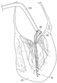
도 16은 카테터의 핸들에 부착되고 이로부터 연장되는 복수의 대체용 코드들을 구비하는 앵커를 좌심실의 심첨에 전달하는 횡-중격 카테터를 보여준다.
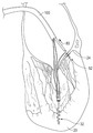
도 17은 봉합사에 연결된 스트레인 릴리프 앵커를 전달하기 위하여 승모판엽을 통해서 피어싱 도구를 전달하는 횡-중격 카테터를 보여준다.
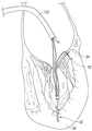
도 18은 봉합사 루프로 승모판엽을 뚫고 승모판엽을 통해서 봉합사 루프를 전달하는 횡-중격 카테터를 보여준다.
도 19는 승포판엽의 심실 측으로 스트레인 릴리프를 전달하여, 피어싱 도구를 통해서 또는 피어싱 도구와 함께 전달하기 위해 스트레인 릴리프가 노출되게 하는 횡-중격 카테터를 보여준다.
도 20은 스트레인 릴리프와, 승모판엽으로부터 인출되는 피어싱 도구를 전달하는 횡-중격 카테터를 보여준다.
도 21은 카테터 핸들로부터 재차 연장되는 봉합사 루프와 말단 앵커에 연결되어 있는 스트레인 릴리프를 전달하는 횡-중격 카테터를 보여준다.
도 22는 말단 앵커에 봉합사 로크를 전달하는 횡-중격 카테터를 보여주는데, 여기서 봉합사 로크는, 승모판엽 및 말단 심첨 앵커에 연결된 최종적인 식립 봉합사의 위치와 장력을 조절하기 위해 카테터 핸들을 통해 봉합사의 근위단으로부터 장력을 인가하는 동안에, 봉합사 꼬리 상에서 전진된다.
도 23은 말단 심첨 앵커를 승모판엽에 고정시키는 연속 봉합사 루프를 보여주는데, 여기서 승모판엽 앵커는 확대되지 않은 부위에서 볼 수 있는 바와 같이 단면 플랜지 내지 단면형으로 되어 있을 수 있다.
도 24는 연속 루프가 말단 심첨 앵커와 승모판엽 상의 스트레인 릴리프 요소와 함께 최종 위치로 전달되는 실시예를 보여준다.
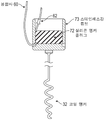
도 25는 최종 위치조정을 위한 봉합사 로크의 전달 전에 봉합사의 움직임을 제한하도록 구성되는 스테인레스강 튜브 및 실리콘 앵커 플러그로 구성되는 말단 심첨 앵커의 예를 보여준다.
도 26은 우심방과 좌심방으로부터 격막를 관통하는 카테터를 보여준다.
도 27은 좌심실의 심첨 안으로 회전에 의해 고정되는 앵커를 보여준다.
도 28은 카테터를 통해 다시 되돌아가도록 연장되는 봉합선이 부착되어 있는 제 위치의 말단 심첨 앵커와, 제대로 위치하게 되었을 때 발사될 수 있는 바늘로 승모판엽을 포착하도록 노출되는 연장 아암을 보여준다.
도 29는 승모판엽과 접촉하는 연장 아암과, 승모판엽의 심방 측에 봉합사 루프를 노출시키기 위하여, 판엽을 관통하는 봉합사 루프에 연결된 바늘을 보여준다.
도 30은 봉합사 루프를 포착하고 카테터를 통해 회수하기 위한 루프-올가미를 수용하기 위해, 승모판엽을 관통하여 판엽의 심방 측으로 노출된 봉합사 루프를 보여준다.
도 32는 봉합사가 말단 심첨 앵커를 포함하는 경로 주위에서 봉합사가 루프를 형성할 때, 승모판엽의 뒤쪽으로 봉합사 로크를 전달하는 카테터를 보여준다.
도 33은 양 단부를 적합하게 팽팽히 한 후에 봉합사를 함께 잠그는 두 판엽에 봉합사 로크를 전달하기 위해 봉합사 단부들를 수용하는 제2 카테터를 보여준다.
도 34는 승모판엽의 위와 아래 위치에 자리잡은 봉합사 로크의 최종 위치를 보여주는 것으로서, 여기서 승모판엽에 연결된 말단 심첨 앵커의 최종 임플란트를 남겨두고 봉합사 단부들은 절단된다.
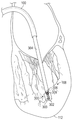
도 35a는 좌심실 내에서의 새로운 유두근의 부착을 보여준다.
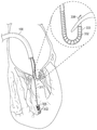
도 35b는 승모판을 통해 전진하는 조종가능한 판엽 천자 카테터를 보여준다.
도 35c는 적어도 약 180°의 각도만큼 굴절된 조종가능한 판엽 천자 카테터를 보여준다.
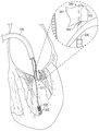
도 35d 내지 35g는 판엽의 천자와, 접힘가능한 거어즈 형태의 판엽 앵커의 전개를 보여준다.
도 35h는 전개용 카테터를 통해 근위 방향으로 연장되는 심실 봉합사와 판엽 봉합사를 보여준다.
도 35ia 내지 도 35id는 T-태그 타입 판엽 앵커의 전개를 보여준다.
도 35ja 내지 도 35j-4는 반지름방향으로 확장가능한 조직 앵커의 전개를 보여준다.
도 35k는 새로운 유두근의 근위 단부 근처에 있는 지렛목을 개략적으로 보여준다.
도 35l은 전개 시스템의 제거 이전의 승모판 기능 검증을 보여준다.
도 35m은 소망하는 수준의 장력 조정 이후의 심실 봉합사에 대한 판엽 봉합사의 부착을 보여준다.
도 36n은 새로운 건삭 구조체를 제 위치에 둔 상태에서의 판엽 봉합사 및 심실 봉합사의 절단을 보여준다.
도 36o는 복합 굴절 구성을 구비하는 판엽 천자 카테터의 말단에 있는 조종가능 부위를 보여준다.
도 36a는 루프 포획된 유두근의 사진으로서 처음 포착된 상태의 구성을 보여준다.
도 36b는 절단 단계가 수행되는 것이 바람직한 영역에 있는 건삭 쪽으로 당겨올려지는 루프 포획된 유두근을 보여준다.
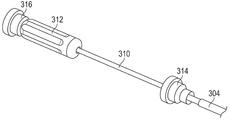
도 37은 건삭 절단 공구의 일 실시예를 보여준다.
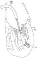
도 38a는 좌심실의 심첨 근처에서의 나선형 앵커 설치를 묘사한 것이다.
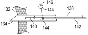
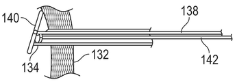
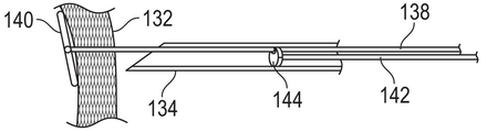
도 38b는 말단의 굴절 튜브를 사용하여 판엽의 심실 측에 판엽 앵커 전달 서브 시스템을 위치시키는 것을 묘사한 것이다.
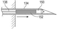
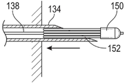
도 38c는 심실 판엽 전달 서브시스템의 원위 단부에 배치된 바늘을 사용하여 판엽에 천공하는 것을 묘사한 것이다.
도 38d는 감소된 반지름방향 단면 구조에서 바늘을 통해 거어즈 판엽 앵커를 전진시키는 것을 묘사한 것이다.
도 38e는 확장된 반지름방향 단면 구조로 확장되는 거어즈 판엽 앵커를 묘사한 것이다.
도 38f는 봉합사를 판엽의 심방측에 앵커 고정시키기 위하여 거어즈 판엽 앵커가 붕괴된 형태로 접혀지는 것을 묘사한 것이다.
도 38g는 봉합사 전달 서브시스템을 통해서 판엽 앵커 봉합사와 심실 앵커 봉합사를 위로 봉합사 로크를 전진시켜서 판엽 앵커를 심실 앵커에 연결시키는 것을 묘사한 것이다.
도 38h는 장력이 조절되고 봉합사 꼬리가 절단된 후의 고정 위치에서의 봉합사 로크를 묘사한 것이다.
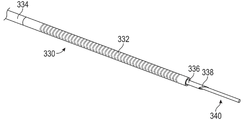
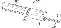
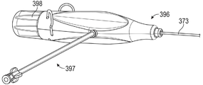
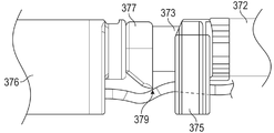
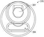
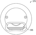
도 39a는 심실 앵커 전달 서브시스템의 원위 단부의 사시도이다.
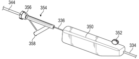
도 39b는 심실 앵커 전달 서브시스템의 근위 단부의 사시도이다.
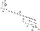
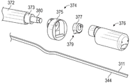
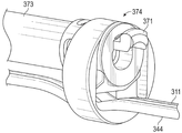
도 39c는 심실 앵커 전달 서브시스템의 원위 단부의 부분분해 사시도이다.
도 40a 내지 도 40f는 판엽 앵커 전달 서브시스템과 그 컴포넌트에 대한 다양한 뷰를 보여준다.
도 40a는 서브시스템의 원위 단부의 사시도이다.
도 40b는 서브시스템의 근위 단부의 사시도이다.
도 40c는 서브시스템의 원위 단부의 분해사시도이다.
도 40d는 굴절 튜브의 사시도이다.
도 40e는 판엽 앵커 전달 서브시스템의 굴절 튜브의 천이영역의 측면도이다.
도 40f는 판엽 앵커 전달 서브시스템의 굴절 튜브의 천이영역의 측면도로서, 도 40e에 묘사된 것에 수직인 방향에서 본 측면도이다.
도 41a는 봉합사 로크 전달 서브시스템의 원위 단부의 사시도이다.
도 41b는 봉합사 로크 전달 서브시스템의 근위 단부의 사시도이다.
도 41c는 봉합사 로크 전달 서브시스템의 원위 단부의 부분분해 사시도이다.
도 41d는 커터 어셈블리의 원위 단부의 사시도이다.
도 41e는 봉합사 로크 전달 서브시스템의 커팅 어셈블리 부분의 측면도로서, 절단되기 이전의 봉합사를 유지하기 위하여 커터 헤드가 전진되지 않은 상태의 구성을 보여준다.
도 41f는 봉합사 로크 전달 서브시스템의 커팅 어셈블리 부분의 측면도로서, 봉합사를 절단하기 위하여 커터 헤드가 전진된 상태의 구성을 보여준다.
도 41g는 봉합사 로크와, 상기 봉합사 로크에 맞물리도록 구성된 토크 드라이버의 원위 단부의 측면도이다.
도 41h는 봉합사 로크의 근위 단부에 대한 뷰를 묘사하고 있다.
도 41i는 봉합사 로크의 원위 단부에 대한 뷰를 묘사하고 있다.
도 42는 두 개의 유두근 사이에서 선천적 건삭에 실질적으로 평행하도록 정렬될 수 있게 식립되는 새로운 건삭 구조를 개략적으로 보여준다.
도 43a는 거어즈의 두 평탄 시트 사이에 봉합사의 원위 단부를 통합함으로써 형성되는 거어즈를 개략적으로 보여준다.
도 43b는 도 43a에 도시된 거어즈의 단면도이다.
도 43c는 붕괴가능한 앵커를 형성하기 위해 봉합사 꼬리가 다시 꿰어질 수 있는 개구들을 포함하는 도 43a의 거어즈를 개략적으로 보여준다.Figure 1 shows the mitral annulus attached to the suture delivered through the catheter.
2 shows a terminal anchor delivered through a catheter and attached to a suture connected to the mitral annulus.
Figure 3 shows a terminal anchor with suture lines for later attachment to the mitral valve or mitral valve annulus, which is secured by rotation to the apex of the heart.
4 shows a terminal anchor with suture lines attached to the mitral valve or mitral valve annulus, which is secured by rotation to the apex of the heart.
5 shows a terminal anchor attached to the apex of the heart and protruding above the apex of the heart to be approximately flush with the top of the papillary muscle.
6 shows a terminal anchor attached to the apex of the heart, protruding above the apex of the heart to be approximately flush with the top of the papillary muscle, and attached to the mitral annulus and / or mitral valve.
7 shows a terminal anchor attached to the apex of the heart, protruding above the apex of the heart to be approximately the same height as the top of the papillary muscle, and attached to a loop suture across the catheter.
8 is a catheter-delivered suture loop that penetrates the mitral valve leaf with a strain relief at the ventricular side of the mitral valve leaf and a terminal anchor at the bottom of the left ventricle, with final suture tension adjustment being maintained with a suture lock advanced over the suture tail. Shows.
9 shows a catheter-delivered suture line penetrating the mitral valve leaf with a strain relief on the ventricular side of the mitral leaf, and the suture lock advancing to the atrial side of the mitral leaf to secure the suture tail before cutting the suture.
10 shows a catheter-delivered suture line penetrating the mitral valve leaf with a strain relief at the ventricular side of the mitral leaf, and the suture lock advancing to the atrial side of the mitral leaf to fix the suture tail. The other end of the suture tail extends from the catheter handle through the catheter and traverses around the terminal anchor at the bottom of the left ventricle to tension the suture. Once the suture tension is adjusted by the user, the second suture lock can be advanced on the final suture tail.
11 is a loop through a mitral leaf with a strain relief on the ventricular side of the mitral leaf and passing through a strain relief and a terminal anchor at the bottom of the left ventricle, where the final suture tension adjustment is advanced over the suture tail. Show the catheter-delivery suture line that is maintained as. Stably holding the leaflets and providing a force corresponding to the force the strain relief punctures can be achieved using a refrigeration catheter approaching the mitral valve.
12 is a loop through a mitral valve and with a strain relief to be delivered to the ventricular side of the mitral valve, passing through the strain relief and a terminal anchor at the bottom of the left ventricle, with the final suture tension being adjusted to the suture tail. Show the catheter-delivery suture line that is held up with the suture lock advanced. The stable holding of the leaflets and providing a force corresponding to the force the strain relief punctures is realized by the freezing catheter approaching the mitral valve.
FIG. 13 is a view of the atrial side from which the mitral valve annulus is penetrated and the terminal anchor is positioned with respect to the congenital papilla in some embodiments.
FIG. 14 is a view of the atrial side of the mitral valve annulus in some embodiments, with the distal anchor installed so as to be positioned relative to the congenital papilla.
FIG. 15 shows various anchors with vertical ridges for attaching to the apical of the left ventricle, bringing the connection point closer to the height of the papillary muscle, simulating an accurate angle and mating to a new cord connection, which embodiments are coiled. Curved wires and laser cut hypotubes.
FIG. 16 shows a transverse septal catheter that delivers an anchor with a plurality of replacement cords attached to and extending from the handle of the catheter to the apical of the left ventricle.
17 shows a transverse septal catheter delivering a piercing tool through the mitral valve to deliver a strain relief anchor connected to the suture.
18 shows a transverse septal catheter that punctures the mitral leaf with a suture loop and delivers the suture loop through the mitral leaf.
FIG. 19 shows a transverse septal catheter that delivers a strain relief to the ventricular side of the mitral leaflet to expose the strain relief for delivery through or with a piercing tool.
20 shows a strain relief and a transverse septal catheter delivering a piercing tool withdrawn from the mitral valve.
FIG. 21 shows a transverse septal catheter carrying a suture loop extending back from the catheter handle and a strain relief connected to the distal anchor.
FIG. 22 shows a transversely septal catheter delivering a suture lock to a distal anchor, wherein the suture lock is proximal to the suture through a catheter handle to adjust the position and tension of the final placement suture connected to the mitral valve and distal apical anchor. During tension application from the stage, it is advanced on the suture tail.
Figure 23 shows a continuous suture loop that secures the terminal apical anchor to the mitral valve, where the mitral leaf anchor can be of the cross-sectional flange to cross-sectional shape as seen in the non-expanded area.
FIG. 24 shows an embodiment where the continuous loop is delivered to its final position along with the terminal apex anchor and strain relief elements on the mitral valve leaflet.
FIG. 25 shows an example of a terminal tip anchor consisting of a stainless steel tube and a silicone anchor plug configured to limit suture movement prior to delivery of the suture lock for final positioning.
26 shows a catheter penetrating the septum from the right atrium and the left atrium.
Figure 27 shows an anchor secured by rotation into the apex of the left ventricle.
FIG. 28 shows the terminal apical anchor in place with sutures attached extending back through the catheter, and an extension arm exposed to capture the mitral valve with a needle that can be launched when properly positioned.
FIG. 29 shows an extension arm in contact with the mitral leaf and a needle connected to the suture loop penetrating the leaf to expose the suture loop to the atrial side of the mitral leaf.
FIG. 30 shows suture loops exposed through the mitral lobe to the atrial side of the leaflets to accommodate loop-noose for capturing the suture loops and withdrawing through the catheter.
FIG. 32 shows a catheter that delivers suture locks to the back of the mitral valve when the sutures form a loop around the path that includes the terminal apical anchors.
FIG. 33 shows a second catheter receiving the suture ends to deliver suture locks to the two leaflets locking the suture together after proper tensioning both ends.
FIG. 34 shows the final position of the suture locks positioned in the upper and lower positions of the mitral valve, where the suture ends are cut leaving the final implant of the terminal apical anchor connected to the mitral leaf.
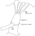
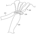
35A shows attachment of new papillary muscles in the left ventricle.
35B shows a steerable leaflet catheter advancing through the mitral valve.
35C shows the steerable leaf puncture catheter refracted by an angle of at least about 180 °.
35D-35G show the puncture of leaflets and the leaflet anchors in the form of collapsible gauze.
35H shows ventricular sutures and leaf sutures extending proximally through a developing catheter.
35ia-35id show the development of the T-tag type leaf anchor.
35ja-35j-4 show the deployment of tissue anchors that are radially expandable.
35K schematically shows the lever near the proximal end of the new papillary muscle.
35L shows mitral valve functional verification prior to removal of the deployment system.
35M shows the attachment of leaf leaf sutures to ventricular sutures after the desired level of tension adjustment.
36N shows cleavage of the leaf sutures and ventricular sutures with the new keying structure in place.
36O shows the steerable portion at the distal end of a leaf puncture catheter with a compound refractive configuration.
36A shows the configuration of the first captured state as a picture of the loop trapped papillary muscle.
36B shows the loop trapped papillary muscle pulled towards the abdomen in the area where the cutting step is preferably performed.
37 shows one embodiment of a dry cut tool.
38A depicts the installation of a spiral anchor near the apex of the left ventricle.
38B depicts positioning the leaflet anchor delivery subsystem on the ventricular side of the leaflet using a distal refraction tube.
38C depicts puncturing the leaflet using a needle placed at the distal end of the ventricular leaflet delivery subsystem.
38D depicts advancing a gauze leaf anchor through a needle in a reduced radial cross-sectional structure.
38E depicts a gauze leaflet anchor extending into an extended radial cross sectional structure.
38F depicts the gauze leaflet anchor collapsed in collapsed form to anchor the suture to the atrium side of the leaflet.
38G depicts connecting leaflet anchors to ventricular anchors by advancing leaflet sutures and ventricular anchor sutures upward through the suture delivery subsystem.
38H depicts suture lock in a fixed position after tension is adjusted and the suture tail is cut.
39A is a perspective view of the distal end of the ventricular anchor delivery subsystem.
39B is a perspective view of the proximal end of the ventricular anchor delivery subsystem.
39C is a partially exploded perspective view of the distal end of the ventricular anchor delivery subsystem.
40A-40F show various views of leaflet delivery subsystems and their components.
40A is a perspective view of the distal end of a subsystem.
40B is a perspective view of the proximal end of the subsystem.
40C is an exploded perspective view of the distal end of a subsystem.
40D is a perspective view of the refractive tube.
40E is a side view of the transition region of the articulation tube of the leaflet anchoring subsystem.
FIG. 40F is a side view of the transition region of the articulation tube of the leaflet anchoring subsystem, viewed from a direction perpendicular to that depicted in FIG. 40E.
41A is a perspective view of the distal end of the suture lock delivery subsystem.
41B is a perspective view of the proximal end of the suture lock delivery subsystem.
41C is a partially exploded perspective view of the distal end of the suture lock delivery subsystem.
41D is a perspective view of the distal end of the cutter assembly.
FIG. 41E is a side view of the cutting assembly portion of the suture lock delivery subsystem, showing the configuration with the cutter head not advanced to hold the suture before being cut. FIG.
41F is a side view of the cutting assembly portion of the suture lock delivery subsystem, showing the configuration with the cutter head advanced to cut the suture.
41G is a side view of a suture lock and a distal end of a torque driver configured to engage the suture lock.
41H depicts a view of the proximal end of the suture lock.
41I depicts a view of the distal end of the suture lock.
FIG. 42 schematically shows a new keying structure that is placed so that it can be aligned substantially parallel to the natural keying between two papillary muscles.
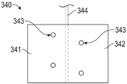
43A schematically shows the gauze formed by integrating the distal end of the suture between two flat sheets of gauze.
FIG. 43B is a cross-sectional view of the gauze shown in FIG. 43A.
FIG. 43C schematically shows the gauze of FIG. 43A including openings in which the suture tail may be resewn to form a collapsible anchor.
파열된 건삭 또는 나풀거리는 동요 건삭을 부착하는 실시예는 대퇴정맥을 통해 전달되어 하대정맥(IVC: inferior vena cava) 내부에서 상측으로 그리고 승모판륜에 대한 부착이 이루어지는 좌심방까지 심실간의 중격을 가로질러 전달되는 카테터를 포함할 수 있다. 이 부착은 승모판륜 조직이나, 승모판엽이 승모판륜이나 그 근처에서 심방 조직과 만나는 국소 조직에 회전이나, 피어싱 즉 봉합사에 끼움으로써 판륜에 삽입되는, 앵커를 통과하는 단일 봉합사 루프일 수 있다. 상기 앵커는 조직 내부로의 회전에 의해 설치되고 건삭 치환을 위한 봉합사 수용부를 가지거나 사전부착의 방식으로 코드가 부착되어 있는 코일 형태의 와이어 앵커(coiled-wire anchor)로 구성될 수 있다.An embodiment of attaching a ruptured or fluttering agitated muscle is delivered through the femoral vein and transversely between the ventricular septum to the upper atrium inside the inferior vena cava (IVC) and to the left atrium where attachment to the mitral annulus occurs. Catheter to be included. This attachment may be a single suture loop passing through the anchor, which is inserted into the annulus by rotation in the mitral annulus tissue or local tissue where the mitral lobe meets at or near the atrial tissue, or by piercing, or fitting into the suture. The anchor may be configured as a coiled-wire anchor installed by rotation into the tissue and having a suture receptacle for dry replacement or to which the cord is attached in a pre-attached manner.
승모판륜과의 연결은 피어싱, 후크 또는 코르크스크류 고정 장치를 통한 안정된 앵커와 같이 안전하고 양호한 부착 지점을 제공할 수 있다. 이 부착 지점에 코드가 연결되어, 승모판엽 위에 걸쳐지고 좌심실의 심첨(apex)에 부착 내지 앵커고정(anchoring)될 수 있다. 또한 코드는 전첨판 또는 후첨판에서 어느 위치에서든 피어싱될 수 있다. 코드는 종래에 건삭 재건 수술용으로 사용되던 것과 같이 곡면형의 또는 편평한 폴리테트라플루로에틸렌(PTFE), 폴리에틸렌(PE), 또는 나일론으로 제작될 수 있다.The connection with the mitral annulus can provide a secure and good attachment point, such as a stable anchor through a piercing, hook or cork screw anchor. The cord is connected to this point of attachment so that it can span over the mitral valve and attach or anchor to the apex of the left ventricle. The code can also be pierced anywhere in the leading or trailing edge. The cord may be made of curved or flat polytetrafluoroethylene (PTFE), polyethylene (PE), or nylon as was conventionally used for dry reconstructive surgery.
일부 실시예에 있어서, 상기 코드는 새로운 건삭(neo chord) 내지 인공 건삭(prosthetic chord)의 역할을 할 수 있다. 어떤 실시예에서 상기 코드는 표준 봉합사일 수 있다. 일부 실시예에서는, 하나 이상의 추가적인 재건 요소가 코드 상에 고정될 수 있다. 예를 들어, 튜브 구조물이 상기 전달 장치를 통해 상기 코드 위로 전진(예컨대, 미끄러져 이동)될 수 있다. 상기 구조물은 코드의 길이 방향으로 적절하게 스스로를 자기위치조정할 수 있게 구성되거나, (예컨대, 상기 구조물의 근위 및/또는 원위에 잠금 부재를 배치함으로써) 상기 코드의 길이를 따라 적절한 위치에서 코드에 고정될 수 있다. 구조물을 제자리에 위치시키기 위하여, 임의의 적절한 잠금 부재가 사용될 수 있다. 잠금 부재는 권측될 수 있거나(cimpable), 기계식 잠금 부재를 구비하거나, 그리고/또는 코드 위로 이동시키기 위해서는 임계치 이상의 힘이 필요하도록 마찰력에 의해 맞물릴 수 있다 . 임의의 적합한 유형의 잠금 부재가 사용될 수 있다. 잠금 부재는 본 명세서의 다른 곳에 기재된 봉합사 로크와 유사할 수 있다. 일부 실시예에서, 잠금 부재는 코드 상에서 원위 방향으로 그리고 근위 방향으로 전진될 수 있게 구성될 수 있다. 일부 실시예에서는, 잠금 부재가 일방향으로만(예컨대, 코드 상에서 멀어지는 방향으로만) 전진할 수 있게 구성될 수도 있다. 일부 실시예에서는, 추가적인 재건 구조물이 코드의 길이 방향으로 근위 단부에, 원위 단부에, 또는 주기적으로 고정될 수 있다. 상기 코드는 재건 구조물의 근위 또는 원위 단부에 부착될 수 있다. 예를 들어, 2 개의 코드를 사용하되, 하나는 구조물의 근위 단부에 부착되고, 다른 하나는 구조물의 원위 단부에 부착되게 할 수 있다. 일부 실시예에서, 상기 코드는 재건 구조물에, 예를 들어 재건 구조물의 근위 단부 및/또는 원위 단부에 연결될 수 있고(예컨대 구조물에 삽입되거나 구조체 상의 루프를 둘러쌀 수 있고), 구조물의 길이를 따라 평행하게 연장될 수도 있다. 상기 재건 구조물은 하나 이상의 생리학적 조직과 접촉하도록(예컨대, 판엽과 접하도록) 구성될 수 있고, 및/또는 생리학적 구조(예를 들어, 유두근)의 기계적/구조적 특성을 복제하도록 구성될 수 있다.In some embodiments, the cord may serve as a neo chord or prosthetic chord. In some embodiments, the cord may be a standard suture. In some embodiments, one or more additional reconstruction elements may be fixed on the code. For example, a tube structure may be advanced (eg, slipped) over the cord through the delivery device. The structure may be configured to self-position itself appropriately in the longitudinal direction of the cord, or to be secured to the cord at an appropriate location along the length of the cord (eg, by placing a locking member proximal and / or distal of the structure). Can be. Any suitable locking member can be used to position the structure in place. The locking member may be crimped, provided with a mechanical locking member, and / or engaged by friction to require a force above a threshold to move over the cord. Any suitable type of locking member can be used. The locking member may be similar to the suture lock described elsewhere herein. In some embodiments, the locking member may be configured to be advanced in the distal direction and the proximal direction on the cord. In some embodiments, the locking member may be configured to be able to advance only in one direction (eg, away from the cord). In some embodiments, additional reconstruction structures may be secured to the proximal end, distal end, or periodically in the longitudinal direction of the cord. The cord may be attached to the proximal or distal end of the reconstruction structure. For example, two cords may be used, one attached to the proximal end of the structure and the other attached to the distal end of the structure. In some embodiments, the cord may be connected to the reconstruction structure, eg, at the proximal end and / or distal end of the reconstruction structure (eg, inserted into or enclosing a loop on the structure) and along the length of the structure. It may extend in parallel. The reconstructive structure may be configured to contact one or more physiological tissues (eg, in contact with leaflets), and / or may be configured to replicate the mechanical / structural properties of the physiological structure (eg, papillary muscle). .
승모판륜에 대한 앵커고정은 파열된 건삭을 심장박동시의 움직임으로 인하여 포착하기 어려운 승모판엽에 대하여 움직이지 않는 양호한 부착 방안이 될 수 있다. 상기 움직임은 기계적인 그립 도구, 석션 튜브, 또는 냉동 카테터(cryo-catheter)로 동요 판엽을 포회갛여 견고하게 붙잡아둠으로써 멈추게 할 수 있는데, 이에 대해서는 일부 도시된 실시예와 관련하여 아래에서 상세하게 기술한다. 상부 앵커가 승모판륜에 양호하게 부착됨에 따라, 코드는 승모판엽 위로 그리고 기존의 건삭들 사이에 걸쳐져서, 판엽에 대한 횡방향 위치를 한정하게 된다. 기존의 건삭들 사이에 판엽이 위치하게 되면, 인공 건삭의 상부 앵커 지점에 양호한 앵커를 제공하게 되고, 인공 건삭이 기존의 건삭을 통과하는 안전한 장소를 제공하게 되며, 좌심실의 심첨에 다른 양호한 앵커 위치를 제공할 수 있는 기반을 제공하게 된다. 대체용 코드 즉, 인공 건삭은 하나의 봉합사 가닥일 수도 있고, 전술한 경로를 상하로 오르내려서 물건을 운반하는 경로를 제공하는 복수의 코드일 수도 있다.Anchor fixation to the mitral annulus can be a good attachment method that does not move against the mitral valve, which is difficult to capture due to the movement of the ruptured tendon. The movement can be stopped by mechanically holding a grip tool, suction tube, or cryo-catheter by holding the agitated leaf tightly and firmly, as described in detail below in connection with some illustrated embodiments. do. As the upper anchor is well attached to the mitral annulus, the cord is spanned over the mitral valve leaf and between existing keystrokes, thereby defining the transverse position relative to the leaf leaf. The presence of leaflets between the existing keystrokes provides a good anchor to the upper anchor point of the artificial keying, provides a safe place for the artificial keying to pass through the existing keying, and other good anchoring positions at the apical of the left ventricle. It will provide a foundation to provide. The replacement cord, ie, the artificial dry, may be a single suture strand, or may be a plurality of cords that provide a route for carrying goods by moving up and down the path described above.
좌심실 내에 위치할 수 있는 하단 앵커는 회전 나사 또는 플러그를 통해 고정되어 코드를 양호하게 지탱할 수 있다. 상기 앵커는 높이가 짧아서 심첨의 기저에 가까울 수도 있고, 좌심실의 심첨 위에 있고 약 20~22 밀리미터(㎜)의 길이를 갖는 선천적 유두근에 더 잘 매칭될 수 있도록 보다 긴 길이를 가질 수도 있다. 일부 실시예에서, 상기 앵커는 상기 심첨 위에서 5 ㎜ 이하, 5 ㎜, 10 ㎜, 15 ㎜, 20 ㎜, 25 ㎜, 30 ㎜, 35 ㎜, 40 ㎜, 45 ㎜, 50 ㎜, 또는 50 ㎜ 이상, 및/또는 상기 값들 사이의 범위의 길이만큼 연장될 수 있다. 하나의 코드 또는 복수의 코드가 좌심실 기저부에 있는 하나 이상의 앵커에 부착될 수 있다. 상기 앵커는 형광 투시법으로 볼 수 있는 식립가능 등급의 스테인레스강, 니티놀, 또는 여타 금속 물질, 또는 PEEK, PTFE 또는 여타 식립가능 물질과 같은 고분자 재료로 제작될 수 있다. 고분자 재료들은 필요에 따라 가시성을 높이기 위한 방사선불투과성 마커로 도핑될 수 있다.The bottom anchor, which may be located in the left ventricle, may be secured through a rotating screw or plug to better support the cord. The anchor may be short in height and close to the base of the apex, or may have a longer length to better match the congenital papillae above the apex of the left ventricle and having a length of about 20-22 millimeters (mm). In some embodiments, the anchor is 5 mm or less, 5 mm, 10 mm, 15 mm, 20 mm, 25 mm, 30 mm, 35 mm, 40 mm, 45 mm, 50 mm, or 50 mm or more above the core, And / or by a length in a range between the values. One cord or a plurality of cords may be attached to one or more anchors at the left ventricular base. The anchor may be made of a graftable grade stainless steel, nitinol, or other metal material, or polymer material, such as PEEK, PTFE or other implantable material, as seen by fluoroscopy. Polymeric materials may be doped with radiopaque markers to increase visibility as needed.
앵커고정(anchoring) 시스템의 일 실시예는 좌심실에 결합되거나 부착되는 심첨 조직 앵커, 및 상기 심첨 조직 앵커로부터 부착부를 돌출시키는 융기부(riser)를 구비할 수 있으며, 하나의 물질로 구성되거나 고분자 및 금속 성분을 포함하는 물질들의 결합으로 구성될 수도 있다. 이러한 구성은 전체적으로 강성을 가질 수도 있고, 제어되는 동작과 유연성을 위한 움직임이나 탄성 부위 내지 탄성 부위들을 가질 수 있도록 해주는 가요성 이음새를 구비할 수도 있다. 이것은 길이 방향으로 형상이 변화하는 곡면 교차 구조(round crossing profile)나 여타 구조로 구성될 수 있다. 직경은 약 6 내지 24 프렌치(2 내지 8 ㎜)이고 길이는 약 20 내지 40 ㎜이며, 중심축을 따라 일반적으로 배치되는 가이드 와이어가 있거나 없는 조종가능한(steerable) 카테터를 통해 운반된다. 일단 상부 판엽 앵커가 승모판륜이나 판엽에 부착된 후 승모판엽 위로 늘어뜨려지고 하부 앵커에 추가적으로 결합되면, 실시간 이미징/모니터링을 통해 판엽 움직임과 역류 감소를 모니터링하면서 장력을 이용하여 조정하는 것이 가능해진다. 마지막 단계는 코드를 팽팽하게 하고, 잠근 후, 전달 시스템으로부터 분리하는 것이다. 코드에 가해지는 장력은 연결된 승모판엽의 스트레인 릴리프에 장력을 인가하게 되며, 이와 같은 상태에서 엘에스아이 솔루션즈사(LSI Solutions)의 Cor-Knot와 같은 로킹 장치를 코드 아래로 내리고, 마지막으로 봉합사 꼬리를 절단할 수 있게 된다.One embodiment of an anchoring system may include a tachycardia anchor that is attached or attached to the left ventricle, and a riser that protrudes the attachment portion from the tachycardia anchor, and may consist of a single material or a polymer and It may also consist of a combination of materials comprising a metal component. Such a configuration may be rigid in its entirety, or may be provided with flexible seams that allow it to have movement or elastic to elastic regions for controlled motion and flexibility. It may consist of a round crossing profile or other structure whose shape changes in the longitudinal direction. The diameter is about 6 to 24 French (2 to 8 mm) and the length is about 20 to 40 mm and is carried through a steerable catheter with or without guide wires generally disposed along the central axis. Once the upper leaf anchor is attached to the mitral valve or leaflet and then hangs over the mitral leaf and additionally coupled to the lower anchor, real-time imaging / monitoring makes it possible to adjust with tension while monitoring leaf motion and backflow reduction. The final step is to tighten the cord, lock it, and detach it from the delivery system. The tension applied to the cord applies tension to the strain relief of the mitral valves connected to it, in this state lowering a locking device such as Cor-Knot from LSI Solutions under the cord, and finally cutting the suture tail. You can do it.
일 실시예(도 1-7 참조)에 따르면, 대체용 코드의 전달 작업은 다음 단계들을 포함한다:According to one embodiment (see FIGS. 1-7), the task of delivering the replacement code includes the following steps:
1. 딜리버리 카테터(100)를 정맥과 대퇴부를 가로질러 진입시킴1.Delivery the
2. 카테터(100)를 우심방(10)으로 전진시킴2. Advancing the
3. 카테터(100)를 중격을 가로질러 좌심방(14)으로 전진시킴(12)3. Advance the
4. 스트레인 릴리프 앵커(18)의 위치조정 및 전달을 위해 카테터(100)를 승모판륜(16)으로 전진시킴4.
5. 승모판엽 그립 도구의 위치조정5. Positioning the Mitral Leaf Grip Tool
6. 스트레인 릴리프 앵커(18)를 승모판륜(16)에 부착6. Attach strain relief anchor (18) to mitral annulus (16)
7. 대체용 코드(22)를 승모판(25) 위로 기존의 건삭(17) 사이에 있도록 전진시킴7. Advance the replacement cord (22) over the mitral valve (25) so that it is in between the existing troughs (17).
8. 코드(22)를 좌심실의 심첨(20)으로 전진시키고, 말단을 심첨(20)에 부착8. Advance the
9. 승모판엽 움직임을 모니터링하면서 코드(22)를 팽팽하게 함9. Tension the cord (22) while monitoring mitral leaf motion
대안으로서, 어떤 실시예들(예컨대, 도 26-34 참조)에서는, 대체 코드 전달 작업이 일부 단계에서 반대 순서로 이루어질 수도 있다.Alternatively, in some embodiments (eg, see FIGS. 26-34), alternative code delivery operations may be performed in some order in the reverse order.
1. 전달 카테터(100)를 대퇴부를 가로질러 진입시킴1. Pass the
2. 카테터(100)를 우심방(10)으로 전진시킴2. Advancing the
3. 카테터(100)를 중격을 가로질러 좌심방(14)으로 전진시킴(12)3. Advance the
4. 전달 카테터(100)를 승모판(24)을 통해서 좌심실의 심첨(20)으로 전진시킴4. Advance the
5. 원위 심실 앵커(예컨대, 회전 앵커(32))를 심첨(20)으로 전달5. Transfer the distal ventricular anchor (eg, rotational anchor 32) to the apex 20
6. 하측 심첨 앵커(30)가 노출되도록 전달 카테터(100)를 인출6. Withdraw the
7. 새로운 코드 봉합선(22) 내지 봉합선들(22)이 노출되도록 전달 카테터(100)의 근위단을 당김7. Pull the proximal end of
8. 각각의 새로운 코드(22) 위로, 승모판엽 스트레인 릴리프를 승모판엽을 통해서 판막의 심실 측에서 전달8. Transfer the mitral valve strain relief through the mitral valve to the ventricular side of each valve, over each new cord (22).
9. 봉합사 로크(26)를 봉합사 꼬리(28) 위로 전진시켜서, 봉합사의 위치를 스트레인 릴리프 앵커의 위치로 고정시킴9. Advance the suture lock (26) over the suture tail (28) to secure the position of the suture to the position of the strain relief anchor.
10. 승모판엽 앵커에서 봉합사 꼬리를 절단10. Cut the suture tail from the mitral valve anchor
11. 봉합사 로크(26)를 카테터 핸들로부터 승모판엽 앵커까지 봉합사 꼬리(28) 위로 전진시킴11. Advance the suture lock (26) over the suture tail (28) from the catheter handle to the mitral valve anchor.
12. 봉합사 로크(26)를 카테터 핸들로부터 말단 심첨 앵커까지 봉합사 꼬리(28) 위로 전진시켜서, 카테터 핸들 외부에 있는 최원위단 봉합사 꼬리로부터 인가되는 그대로 장력을 고정시킴12. Advance the suture lock 26 over the suture tail 28 from the catheter handle to the distal apical anchor, thereby securing tension as applied from the distal most suture tail outside the catheter handle.
13. 말단 심첨 앵커에서 봉합사 꼬리를 절단13. Cut the suture tail from the terminal apical anchor
이 방법의 일부 단계들은 선택적으로 행해지는 것일 수 있다. 적절하다면, 추가적인 단계가 포함될 수 있다. 더욱이, 이 단계들은 임의의 가능한 순서로 재정렬될 수 있다.Some steps of this method may be done selectively. If appropriate, additional steps may be included. Moreover, these steps may be rearranged in any possible order.
도 1 내지 도 7에 따른 실시예를 보다 구체적으로 설명한다. 도 1은 카테터(100)를 통해서 전달된 봉합사(22)가 부착된 상태의 승모판륜(16)을 보여준다. 도 2는 카테터를 통해서 전달되고, 승모판륜에 접속된 봉합사(22)에 부착되는 말단 앵커(32)를 보여준다. 도 3은 추후에 승모판엽(24) 또는 승모판륜(16)에 부착할 수 있도록 봉합사 선들(22)을 구비하며, 심장의 심첨(20)에 회전에 의해 고정되는 말단 앵커(32)를 보여준다. 도 4는 승모판엽(24) 또는 승모판륜(16)에 부착된 봉합사 선들(22)을 구비하며, 심장의 심첨(20)에 회전에 의해 고정되는 말단 앵커(32)를 보여준다. 도 5는 심장의 심첨(20)에 부착되고, 유두근의 상단과 대략 같은 높이가 되도록 심장의 심첨(20) 위로 돌출되는 말단 앵커(32)를 보여준다. 앵커(32)는 연결 지점(72)에 연결되고 일부 실시예에서 약 20~40 ㎜의 길이를 가지는 융기부(70)를 구비할 수 있다. 융기부(70)는 재료, 직경, 강성 등이 앵커(32)의 나머지 부분과 동일하거나 상이할 수 있다. 융기부(70)는 앵커(32)의 나머지 부분과 길이 방향으로 정렬되어 있을 수도 있고, 앵커(32)의 나머지 부분에 대하여 일정 각도로 배치되어 있을 수도 있다. 융기부(70)는 앵커(32)의 나머지 부분에 고정 결합되거나, 관절식으로 결합되거나(예컨대, 조인트/소켓의 사용), 또는 유연하게 결합(예컨대, 상호연결 루프의 사용)될 수 있다. 새로운 건삭의 설치시에 앵커(32)에 가해지는 장력은 심장 및/또는 앵커(32)의 나머지 부분에 대한 융기부(70)의 방향을 결정하거나 변경할 수 있다. 도 6은 심장의 심첨(20)에 부착되고, 유두근의 상단과 대략 같은 높이가 되도록 심장의 심첨(20) 위로 돌출되는 말단 앵커(32)를 보여준다. 말단 앵커(32)는 하나 이상의 봉합선을 통해 승모판륜(16) 및/또는 승모판엽(24)에 부착될 수 있다. 도 7은 심장의 심첨20)에 부착되고, 유두근의 상단과 대략 같은 높이가 되도록 심장의 심첨(20) 위로 돌출되며, 카테터(100)를 관통하여 가로지르는 루프 형태로 되어 있는 봉합사(33)에 부착된 말단 앵커(32)를 보여준다.1 to 7 will be described in more detail. 1 shows the
도 8은 승모판엽(24)의 심실 측에 스트레인 릴리프(52)가 마련된 승모판엽(24)과, 좌심실의 저부에 있는 말단 앵커(32)를, 루프 형태로 카테터를 통해 전달되는 봉합사(50)가 관통할 수 있는 실시예를 보여주는데, 여기서 최종적인 봉합사 장력 조정은 봉합사 꼬리(56) 위로 전진되어 있는 봉합사 로크(54)로 유지된다. 단일 봉합사 루프(50)는 말단 앵커(32)를 스트레인 릴리프(52)에, 직접 말단 앵커로 및/또는 다른 판엽 앵커로, 결합시킬 수 있다. 하나 이상의 루프가 사용될 수도 있다. 일부 실시예에서 봉합사(50)는, 그 자체로 사실상 두 배가 되도록, 말단 앵커(32) 및/또는 스트레인 릴리프(52)에 있는 루프 구조를 통과할 수 있다. 일부 실시예에서 봉합사(50)는, 봉합사(50)의 근위 단부가 한쪽 구멍으로 들어가고 봉합사(50)의 원위 단부가 다른 구멍으로 빠져나오도록, 말단 앵커(32) 및/또는 스트레인 릴리프(52)에 있는 채널을 통과할 수도 있다. 상기 구멍들은 말단 앵커(32) 및/또는 스트레인 릴리프(52)와 같은 쪽에 위치할 수 있다. 상기 구멍들은 말단 앵커(32) 및/또는 스트레인 릴리프(52)와 반대 쪽에 위치할 수도 있다. 말단 앵커(32) 및 스트레인 릴리프(52)로부터 연장되는 봉합사 꼬리(56)의 상대적 길이는 봉합사 로크(54)의 사실상의 최종 위치를 결정할 수 있다. 예를 들어, 스트레인 릴리프(52)로부터 연장되는 봉합사 꼬리(56)의 길이를 최소화함으로써, 봉합사 로크(54)는 스트레인 릴리프(52) 바로 위에 있는 것과 같이 사실상 승모판엽(24)의 심방 측에 위치하게 될 수 있다. 말단 앵커(32)의 근위 단부로부터 연장되는 봉합사 꼬리(56)의 길이를 최소화함으로써, 봉합사 로크(54)는 말단 앵커(32)의 바로 위에 위치하게 될 수 있다. 봉합사 로크(54)는 본 명세서의 다른 곳에서 기재된 것을 포함하여 임의의 적합한 유형의 봉합사 잠금 장치일 수 있다. 스트레인 릴리프(52)는, 접혀진 구조(예컨대, 단면적이 축소된 구조)로 판엽(24)을 통해 삽입되어 판엽(24)의 심실측에서 (예컨대 단면적이 확장된 구조로) 팽창될 수 있도록. 팽창가능한 구조를 포함할 수 있다. 스트레인 릴리프(52)는 자체-팽창될 수 있다. 일부 실시예에서는, 스트레인 릴리프(52)가 본 명세서의 다른 곳에 기재된 바와 같은 거어즈(pledget)일 수 있다. 스트레인 릴리프(52)는 본 명세서의 다른 곳에 기재된 바와 같이 판엽(24) 조직을 천공하기 위한 바늘 또는 다른 적합한 기구를 통해 삽입될 수 있다. 스트레인 릴리프(52)는 바늘의 내강 내부에 보관되고 이 내강을 통해서 전진될 수 있다. 상기 바늘은 스트레인 릴리프(52)를 접혀진 구조로 구속할 수 있다. 스트레인 릴리프(52)는, 스트레인 릴리프로부터 연장되는 봉합사(50)의 근위 단부와 원위 단부가 모두 스트레인 릴리프(52)가 설치되었을 때 판엽(24)의 천공을 통해 연장되는 상태를 유지할 수 있도록, 봉합사(50)에 사전 장착된 상태로(예컨대, 스트레인 릴리프를 꿴 상태로) 판엽(24)을 통해 삽입될 수 있다. 봉합사 로크(54)는 봉합사 꼬리들(56)이 봉합사 로크(54)를 통해 전진하거나 후퇴하는 것을 방지함으로써, 봉합사 로크(54)가 결합된 후에 봉합사 코드를 팽팽한 상태로 유지하고, 봉합사 꼬리(56)가 봉합사 로크(54)에 가깝게 절단될 수 있게 해준다. 봉합사(50)의 꼬리들(56)은, 봉합사 로크(54)로부터 자유롭게 연장될 만큼의 길이를 가질 수 있을 만큼, 봉합사 로크(54)에 인접하거나 봉합사 로크(54)에 가까이 떨어져있도록 직접 절단될 수 있다. 스트레인 릴리프(52) 및 말단 앵커(32)는 체외에서 봉합 루프(50) 상으로 로딩될 수 있으며 임의의 순서로 카테터(100)를 통해 순차적으로 설치될 수 있다.FIG. 8 shows a
도 9는 카테터를 통해 전달되는 봉합사 선 내지 루프(60)가 승모판엽(24)의 심실 측에 스트레인 릴리프(52)가 마련된 승모판엽(24)을 관통할 수 있는 실시예를 보여준다. 스트레인 릴리프(52)는 도 8과 관련하여 설명한 바와 같이 삽입될 수 있다. 본 실시예에서 봉합사 로크(62)는 승모판엽(24)의 심방 측으로 전진하여, 봉합사(60)를 절단하기 전에 봉합사 꼬리를 고정할 수 있다. 봉합사 로크(62)는, 말단 앵커(32)로부터 연장되는 봉합사 꼬리는 고정시키지 않고 스트레인 릴리프(52)로부터 연장되는 꼬리만을 고정시키도록, 봉합사(60)의 하나의 꼬리만을 따라 전진될 수 있다. 봉합 잠금장치(62)는 봉합사에 장력이 가해질 때 봉합사 로크가 승모판엽(24)에 있는 천공을 통해 당겨지는 것을 방지하도록 구성될(예컨대, 크기 및/또는 형상이 정해질) 수 있다. 말단 앵커(32)로부터 연장되는 봉합사 꼬리는 도 10과 관련하여 기술하는 바와 같이 고정될 수도 있다.FIG. 9 shows an embodiment in which the suture line to
도 10은, 도 9와 관련하여 설명한 바와 같이, 카테터를 통해 전달되는 봉합사 선(60)이 승모판엽(24)의 심실 측에 스트레인 릴리프(52)가 마련된 승모판엽(24)을 관통할 수 있으며, 봉합사 꼬리를 고정할 수 있도록 봉합사 로크(54)가 승모판엽(24)의 심f방 측으로 전진하는 실시예를 보여준다. 봉합사 꼬리의 타 단부는 카테터 핸들로부터 카테터(100)를 통해 연장되어, 봉합사를 팽팽하게 할 수 있도록, 좌심실의 저부에 있는 말단 앵커(32) 주위를 가로지르게 된다. 사용자에 의해 봉합사 장력이 조절되면, 제2 봉합사 로크(63)는 최종적인 봉합사 꼬리 상에서 전진되어 최종적인 봉합사 꼬리 상의 위치에 고정될 수 있다. 제2 봉합사 로크(63)는 봉합사에 장력이 가해질 때 상기 봉합사 로크(63)가 말단 앵커(32)를 통해 당겨지는 것을 방지하도록 구성될(예컨대, 크기 및/또는 형상이 정해질) 수 있다.10, as described in connection with FIG. 9, the
도 11은 카테터를 통해 전달되는 봉합사 루프(60)가 승모판엽(24)의 심실 측에 스트레인 릴리프(52)가 마련된 승모판엽(24)을 피어싱 요소(27)(예컨대, 바늘)로 관통할 수 있고 스트레인 릴리프(52)와 좌심실의 저부에 있는 말단 앵커(32)를 거치는 루프 형태로 되어 있으며, 최종적인 봉합사 장력 조정은 봉합사 꼬리(56) 위로 전진되어 있는 봉합사 로크로 유지되는 실시예를 보여준다. 본 실시예의 구성은 도 8~10에 도시된 것과 유사할 수 있다. 판엽을 안정되게 붙잡고 스트레인 릴리프가 천공하는 힘에 대항하는 힘을 제공하는 것은 승모판엽(24)에 찔러지는 냉동 카테터(70)를 사용하여 달성될 수 있다. 상기 냉동 카테터(70)는 동일한 카테터(100)를 통해서 또는 별도의 카테터를 통해서 전달될 수 있다. 상기 냉동 카테터는 승모판엽(24)에 일시적으로 냉각 효과를 인가하여 판엽(24) 조직이 일시적으로 카테터에 부착하게 할 수 있다. 석션 장치, 조직-파지 장치, 추가적인 천공장치 등을 포함하는 다른 유지 장치도 단독으로 또는 조합되어 사용될 수 있다. 판엽(24)에 유지력(retention force)를 제공하는 것은 피어싱 요소(27)의 삽입 중에 판엽(24)에 대항하는 힘을 가하는 것을 유리하게 도울 수 있다.11 shows that a
도 12는 승모판엽(24)을 관통하고, 승모판엽(24)의 심실 측에 전달되어야 할 스트레인 릴리프(52)를 구비하며, 스트레인 릴리프(52)와 좌심실의 저부에 있는 말단 앵커(32)를 거치는 루프 형태로 되어 있고, 최종적인 봉합사 장력 조정이 봉합사 꼬리(56) 위로 전진되어 있는 봉합사 로크로 유지되는 카테터-전달 봉합사 선을 보여준다. 판엽을 안정되게 붙잡고 스트레인 릴리프가 천공하는 힘에 대항하는 힘을 제공하는 것은 승모판엽에 찔러지는 냉동 카테터(70)에 의해 구현된다. 도 12에 도시된 실시예는 도 11에 도시된 실시예와 유사하며, 다만 피어싱 요소(27)가 조직으로부터 인출되어 있다.12 has a
도 13 및 14는 일부 실시예에서 승모판륜(16)이 관통되어 있고 말단 앵커(32)가 선천적 유두근에 대하여 위치하도록 설치된 것을 심방 측에서 본 모습을 도시한 도면이다. 일부 실시예에서는, 전엽 또는 후엽이나 그에 가까운 판륜 조직이 관통될 수 있다. 관통 및 스트레인 릴리프 내지 판엽 앵커의 설치 위치 조정을 통해 판엽에 가해지는 장력의 양에 영향을 줄 수도 있다.13 and 14 show, in some embodiments, the
도 15는 좌심실의 심첨에 부착하기 위한 것으로서, 연결 지점(72)을 유두근의 높이에 더 가깝게 하여 정확한 각도를 시뮬레이션하고 새로운 코드 연결에 정합되게 해주는 수직 융기부(riser)(70)를 구비하는 다양한 앵커 실시예들(32a, 32b, 32c, 32d)을 보여주는데, 이 실시예들은 코일형 곡선 와이어(32a, 32b, 32c)와 레이저 절삭 하이포튜브(32d)를 포함한다. 앵커(32a)는 길이 방향으로 정렬된 끝이 뾰족한 샤프트의 외측을 둘러싸도록 연장되는 하나의 나선형 코일을 포함한다. 일부 실시예에서, 상기 샤프트는 배제될 수 있다. 앵커(32b)는 실질적으로 동일한 피치를 가지고 반대 방향으로 연장되는 2 개의 나선형 코일을 포함한다. 일부 실시예에서는, 앵커(32a)와 같이 끝이 뾰족한 샤프트가 코일 사이에서 연장될 수도 있다. 앵커(32c)는 코일의 근위 단부로부터 원위 단부으로 갈수록 외경이 감소하는 하나의 나선형 코일을 포함한다. 앵커(32d)는 레이저 절삭 하이포튜브로 형성되는 하나의 코일을 포함한다. 일부 실시예에서, 상기 연결 지점(72)는 하나의 닫힌 고리일 수 있다. 봉합사들은 상기 고리에 끼워져 있거나 다른 방식으로 상기 고리에 부착될 수 있다. 일부 실시예에서는, 봉합사 또는 다른 유형의 코드에 대한 다른 유형의 연결방식이 사용될 수도 있다. 앵커(32c)는 지주(strut) 형태로 된 융기부(70)와, 봉합사(60)를 수용할 수 있는 연결 지점(72)를 포함하는데, 상기 봉합사(60)는 실리콘 플러그(74)에 의해 연결 지점(72)에 고정될 수 있다. 임의의 적합한 물질이 플러그에 사용될 수 있다. 상기 연결 지점(72)은 플러그(74)를 수용할 수 있도록 구성된(예컨대, 크기와 형태가 적합한) 채널을 구비할 수 있다. 상기 커넥터는 봉합사가 통과할 수 있도록 채널의 측벽을 관통하여 연장되는 하나 이상의 개구를 포함할 수 있다. 상기 플러그(74)는 상기 채널에 끼워맞춤 결합될 수 있다. 도 15에 도시된 바와 같이, 상기 하나 이상의 봉합사는 채널을 통해서 그리고 측벽의 개구를 통해서 연장될 수 있다. 봉합사는 상기 플러그(74)가 없을 때 설치되는 중에 상기 개구를 통해 자유로이 습동할 수 있어서, 봉합사의 길이 및 장력을 조절할 수 있게 해준다. 상기 플러그(74)는 상기 채널 내부로 삽입되어 상기 채널과 꽉조이게 마찰력에 의한 결합을 형성할 수 있다. 상기 플러그(74)는 상기 하나 이상의 봉합사를 플러그(74)의 외주면과 측벽의 내주면 사이에서 마찰력으로 고정시킬 수 있으며, 이에 따라 앵커(32c)에 대하여 봉합사의 위치를 사실상 고정시킨다. 상기 플러그(74)는 상기 하나 이상의 봉합사의 길이 및 장력을 조절한 후에 설치될 수 있다. 다른 실시예에서는, 봉합사가 채널의 말단에 있는 루프를 통해 연장될 수 있어서, 봉합사가 이를 통해 습동할 수 있게 해준다. 봉합사의 근위단 및 말단은 채널의 근위 개구를 통해 연장될 수 있다. 플러그(74)는 전술한 바와 같이 봉합사를 마찰력으로 고정하여 앵커(32d)에 대한 봉합사의 추가적인 습동을 방지할 수 있다. 본 명세서에 기재된 앵커(32a-32d)의 다양한 특징은 임의로 적합하게 조합되어 사용될 수도 있다.FIG. 15 is for attaching to the apical of the left ventricle, with a variety of
도 16 내지 도 22는 일부 실시예에 따른 다른 방법을 보여준다. 도 16은 카테터(100)의 핸들에 부착되고 이로부터 연장되는 복수의 대체용 코드들(22)을 구비하는 앵커(32)를 좌심실의 심첨(20)에 전달하는 횡-중격(trans-septal) 카테터를 보여준다. 도 17은 봉합사(60)에 연결된 스트레인 릴리프 앵커를 전달하기 위하여 승모판엽(24)을 통해서 피어싱 도구(80)를 전달하는 도 16의 횡-중격 카테터(100)를 보여준다. 도 18은 봉합사 루프(60)로 승모판엽(24)을 뚫고 승모판엽(24)을 통해서 봉합사 루프(60)를 전달하는 횡-중격 카테터(100)를 보여준다. 도 19는 승포판엽(24)의 심실 측으로 스트레인 릴리프(52)를 전달하여, 피어싱 도구(80)를 통해서 또는 피어싱 도구(80)와 함께 전달하기 위해 스트레인 릴리프(52)가 노출되게 하는 횡-중격 카테터(100)를 보여준다. 일부 실시예에서는, 스트레인 릴리프(52)가 본 명세서의 다른 부분에 기술된 바와 같이 노출시에 자체 팽창될 수도 있다. 도 20은 스트레인 릴리프(52)와, 승모판엽(24)으로부터 인출되는 피어싱 도구(80)를 전달하는 횡-중격 카테터를 보여준다. 도 20은 2 개의 스트레인 릴리프가 승모판엽(24)의 반대쪽에 위치하는 실시예를 보여준다. 판엽은 심방측 스트레인 릴리프와 심실측 스트레인 릴리프 사이에 끼워질 수 있다. 심실측 스트레인 릴리프(52)가 제자리를 잡고 장력을 가하여 심실측 스트레인 릴리프(52)가 판엽(24)에 빽빽하게 접촉한 연후에, 상기 방측 스트레인 릴리프가 봉합사 상으로 전진될 수 있다. 스트레인 릴리프들 사이가 느슨해지면 스트레인 릴리프들과 판엽(240 사이의 접촉면이 영향을 받게되어 스트레인 릴리프들이 가하는 압력을 앗아가기 때문에, 스트레인 릴리프들 사이가 느슨해지지 않도록 심방측 스트레인 릴리프는 봉합사에 잠금 또는 고정되도록 구성될 수 있다. 일부 실시예에서는, 심방측 스트레인 릴리프 뒤로 봉합사 로크가 전진되어, 심방측 스트레인 릴리프가 판엽(24) 조직과 빽빽하게 접촉하도록 강제하게 할 수 있다. 일부 예에서는, 스트레인 릴리프를 2개 사용함에 따라, 판엽(24)을 관통하는 천공지점에 야기되는 변형이 감소되고 판엽(24) 조직의 손상이 경감될 수 있다. 도 21은 카테터 핸들로부터 재차 연장되는 봉합사 루프(60)와 말단 앵커(32)에 연결되어 있는 스트레인 릴리프(52)를 전달하는 횡-중격 카테터(100)를 보여준다. 도 22는 말단 앵커(32)에 봉합사 로크(62)를 전달하는 횡-중격 카테터(100)를 보여준다. 봉합사 로크(62)는, 승모판엽(24) 및 말단 심첨 앵커(32)에 연결된 최종적인 식립 봉합사의 위치와 장력을 조절하기 위해 카테터 핸들을 통해 봉합사의 근위단으로부터 장력을 인가하는 동안에, 봉합사 꼬리 상에서 전진된다.16-22 show another method in accordance with some embodiments. FIG. 16 illustrates a trans-septal delivery of an
도 23은, 연속 봉합사 루프가 말단 심첨 앵커(32)를 승모판엽(24) 상의 스트레인 릴리프 요소(52)에 고정시키는, 최종 위치에 있는 실시예를 보여준다. 일부 실시예에서, 상기 연속 루프는 루프를 이루는 봉합사의 꼬리들에 봉합사 로크들을 적용함으로써 형성될 수 있다. 연속 루프 봉합사를 형성하기 위한 임의의 다른 적합한 수단이 사용될 수도 있다. 실시예에 따라서, 승모판엽 앵커 내지 스트레인 릴리프 요소(52)는 도면 중 부분확대 부위에서 볼 수 있는 바와 같이 양면형(예컨대, 양면 플랜지(52b)를 구비)으로 되어 있을 수도 있고, 확대되지 않은 부위에서 볼 수 있는 바와 같이 단면 플랜지(52)로 되어 있을 수도 있다. 양면 플랜지(52b)는 승모판엽 조직의 대향 면에 배치되도록 구성되는 팽창가능한 요소들(예컨대, 팽창가능한 플랜지들)을 포함할 수 있다. 일부 실시예에서, 대향하는 2 개의 플랜지들은 판엽(24)의 천공을 가로지르는 중간 요소를 통해 서로 고정 결합될 수 있다. 플랜지들은 판엽(24)의 보다 넓은 표면영역에 걸쳐 변형을 분산시키도록 구성되는 복수의 스트레인 릴리프 요소들(예컨대, 가요성/변형가능한 루프)을 포함할 수 있다.FIG. 23 shows an embodiment in the final position where the continuous suture loop secures the terminal
도 24는 연속 루프(90)가 말단 심첨 앵커(32)와 승모판엽(24) 상의 스트레인 릴리프 요소(52)와 함께 최종 위치로 전달되는 실시예를 보여준다. 본 실시예는 도 23에 도시 된 것과 유사할 수 있다.FIG. 24 shows an embodiment where the continuous loop 90 is delivered to its final position along with the
도 25는 최종 위치조정을 위한 봉합사 로크(62)의 전달 전에 봉합사의 움직임을 제한하도록 구성되는 스테인레스강 튜브(73) 및 실리콘 앵커 플러그(72)로 구성되는 말단 심첨 앵커(32)의 예를 보여준다. 일부 실시예에서, 플러그(72)는 임시 봉합사 로크로 사용될 수도 있다. 다른 실시예에서, 플러그는 봉합사 위로 전진하는 봉합사 로크(62)에 더해 추가적으로 또는 그 대안으로써 임시 봉합사 로크의 역할을 할 수도 있다. 플러그(72)가 임시로 사용되는 경우에, 플러그(72)는 식립 설치가 완료되기 이전에 제거될 수 있다. 재질은 크기 및/또는 재료의 발전에 따라 다양하게 변경될 수 있다. 일부 구현예에서, 앵커(32)는 도 15에 도시된 앵커(32c)와 동일하거나 유사 할 수 있다.FIG. 25 shows an example of a
도 26~34는 말단 심첨 앵커(32)의 배치 순서가 변경될 수 있는 실시예를 보여준다. 도시된 바와 같이, 도 26은 우심방과 좌심방(14)으로부터 중격(12)을 관통하는 카테터(100)를 보여준다.26-34 show embodiments in which the order of placement of the
도 27은 좌심실의 심첨 안으로 회전에 의해 고정되는 앵커(32)를 보여준다. 앵커(32)는 그 구성에 따라 시계 방향 또는 반시계 방향으로 회전될 수 있다. 본 명세서의 다른 부분에서 기술하는 바와 같이, 앵커(32)는 카테터(100)를 통해 삽입될 수 있는 전달기구(예컨대, 회전 드라이버)에 의해 회동할 수 있다. 아울러, 도시된 실시예에서는 앵커(32)가 좌심실의 심첨 안으로 회전해서 들어가지만, 변형된 실시예에서는 앵커(32)가 좌심실 내의 다른 위치에 고정될 수도 있다. 예를 들어, 아래에서 보다 상세하게 설명하는 바와 같이, 본 명세서에 기재된 방법들과 장치들의 실시예는 앵커(32)가 좌심실 내에서 유두근들 사이에 위치되는 배치에 대해서도 활용될 수 있다. 이와 같은 배치는 앵커(32) 및 승모판엽(24)에서 연장되는 봉합사를 고정된 승모판엽(24)으로부터 연장되는 하나 이상의 건삭과 유리하게 정렬시킬 수 있다.27 shows an
도 28은 체외에 있는 전달 장치의 근위 단부에 카테터(100)를 통해 다시 되돌아가도록 연장되는 봉합선(22)이 부착되어 있는, 제 위치의 말단 심첨 앵커(32)를 보여준다. 봉합사는 본 명세서의 다른 부분에서 기술된 바와 같이 앵커(32)를 통과하는 루프를 형성할 수 있다. 카테터(100)의 연장 아암(94)은 카테터(100)의 말단에 다소 가까운 위치에서카테터의 측면으로 노출될 수 있다. 상기 연장 아암(94)은 카테터(100)의 측면으로부터 근위 방향으로 연장되도록 경사가 부여될 수 있다. 연장 아암은 판엽(24)의 심실 측과 같은 부위에서 승모판엽(24)을 포착하도록 구성될 수 있다. 연장 아암(94)은 팁이 뾰족하거나, 바늘을 포함하거나, 카테터(100) 및 연장 아암(94)을 통해 바늘의 통과를 허용할 수 있다. 판엽(24)은, 판엽(24) 상에 제대로 위치하게 되었을 때 발사되도록 구성된 바늘과, 상호작용을 하게 될 수 있다. 일부 실시예에서, 연장 아암은 카테터(100)를 통해 연장되고 상기 카테터(100)를 통해 독립적으로 말단 방향으로 전진할 수 있고 근위 방향으로 수축될 수 있는 별도의 카테터 상에 형성될 수 있다.FIG. 28 shows the distal
도 29는 승모판엽(24)과 접촉하는 연장 아암(94)과, 승모판엽(24)의 심방 측에 봉합사 루프(60)를 노출시키기 위하여, 판엽(24)을 관통하는 봉합사 루프(60)에 연결된 바늘(96)을 보여준다. 일부 실시예에서, 봉합사 루프는 말단 앵커(32)를 통해 연장되는 봉합사의 한 꼬리로부터 형성될 수 있다. 타 단부는 전달 카테터를 통해서 근위 방향으로 즉, 전달 카테터(100)의 근위 단부 및 체외로 연장될 수 있다. 일부 실시예에서, 봉합사 루프(60)는 이를 통해서 봉합사가 루프를 이루는 고리(ring)일 수 있다. 일부 실시예에서, 봉합사 루프(60)는 바늘(96)과 맞물리는 봉합사 내의 고리일 수 있고, 바늘(96)은 봉합 루프(60)를 유지하고 봉합 루프가 바늘(96)을 통해 근위 방향으로 후퇴하는 것을 방지하도록 구성될 수 있다. 일부 실시예에서는, 4 개의 가닥이 말단 앵커(32)로부터 연장되되, 이중 2 두 가닥이 카테터(100)의 근위 단부까지 연장되고 나머지 두 가닥이 연장되어 봉합사 루프(60)를 형성하도록, 연속적인 봉합사가 말단 앵커(32)를 통해 꿰어져있을 수 있다.29 shows an extension arm 94 in contact with the
도 30은 봉합사 루프(60)를 포착하고 카테터(100)를 통해 회수하기 위한 루프-올가미(99)를 수용하기 위해, 승모판엽을 관통하여 판엽의 심방 측으로 노출된 봉합사 루프(60)를 보여준다. 상기 루프 올가미는 카테터(100)에서 연장 아암(94)에 가까이 위치하는 다른 개구를 통해 전달될 수 있다. 연장 아암(94) 및 루프 올가미 개구는 카테터(100)의 동일한 측면에 위치할 수 있다. 루프 올가미(99)가 봉합사 루프(60)를 유지하고 루프 올가미 개구를 통하여 카테터(100) 내부로 근위 방향으로 회수할 수 있도록(연장 아암(94)을 통해 봉합사 루프를 말단쪽으로 전진시키면서), 루프 올가미(99)는 봉합사 루프(60) 주위에서 줄어들게 구성될 수 있다.30 shows a
도 31은 봉합사 루프(60) 주위에서 닫혀지는 봉합사 루프 올가미(99)와 카테터(100)를 통해 근위 방향으로 인출되는 봉합사를 보여준다. 도 32는 봉합사가 말단 심첨 앵커(32)를 포함하는 경로 주위에서 봉합사가 루프를 형성할 때, 승모판엽의 뒤쪽으로 봉합사 로크(62)를 전달하는 카테터(100)를 보여준다. 봉합사 로크(62) 및 말단 앵커(32)는, 봉합사 로크(62)가 말단 앵커(32)의 연결 지점을 자유롭게 통과하여 판엽(24)의 심실 측에 도달할 수 있도록, 구성될 수 있다. 예를 들어, 봉합사 로크(62)는 말단 앵커(32)에 있는 루프를 통과하도록 구성될 수 있다. 연장 아암(94)은, 판엽(24)이 더 이상 연장 아암(94)에 포착되지 않도록, 이 단계 이전에 또는 이 단계 도중에 수축되어질 수 있다. 본 명세서의 다른 부분에서 기술하는 바와 같이, 일부 실시예에서는 연장 아암이 카테터(100)를 통해 전진되고 이어서 카테터(100)를 통해 인출될 수 있는 내부 카테터의 일부로서 형성될 수 있다.FIG. 31 shows the suture loop drawn proximally through the
도 33은 양 단부를 적합하게 팽팽히 한 후에 봉합사를 함께 잠그는 두 판엽에 봉합사 로크를 전달하기 위해 봉합사 단부들를 수용하는 제2 카테터(101)를 보여준다. 카테터(100)는 봉합사 루프(60)를 지닌 상태로 체외로 인출될 수 있어서, 체외에서 봉합사의 타 단부와 정렬될 수 있다. 제2 봉합사 로크를 봉합사 단부들에 적용하고, 이어서 제2 카테터(101)를 사용하여 체내로 전달할 수 있다. 도 34는 승모판엽(35)의 위와 아래 위치에 자리잡은 봉합사 로크(62)의 최종 위치를 보여주는 것으로서, 여기서 승모판엽(24)에 연결된 말단 심첨 앵커의 최종적인 식립부위를 남겨두고 봉합사 단부들은 절단된다. 두 봉합로크들 사이에 있는 봉합사의 길이에 따라, 제2 봉합사 로크(62)는 판엽(24)에 대하여 다른 위치에 배치 될 수도 있다. 판엽(24)의 대향면에 2 개의 봉합사 로크들을 배치시키면 봉합사 로크들이 스트레인 릴리프의 역할을 할 수도 있다. 일부 실시예에서는, 판엽(24)의 심실 측에 배치되는 제1 봉합사 로크(62)가 생략될 수 있다.FIG. 33 shows a
코드 단부의 종단처리와 봉합사 로킹을 위한 구성 및 장치는, 부착 지점에서의 중심 응력(focal stress)을 줄이기 위하여, 하나 이상의 매듭, 거어즈, 또는 여타 종단 기술을 포함할 수 있다. 고리 조직과 판엽에 대한 천공은 날카로운 바늘 삽입을 통해 달성할 수 있으며, 승모판엽을 통해 바늘을 밀고 위치시키고 구동하도록, 조종가능한 카테터 및 코어 샤프트를 통해 구동될 수 있다. 이 시술은 투시조영술, 초음파 검사에 의한 안내(echo guidance), 또는 기타 적합한 시각화 내지 모니터링 절차에 따라 안내될 수 있다. 판엽의 위치조정 및 격리는 판엽을 잡거나 당기는 기계적인 기법이나, 석션 또는 냉동 카테터를 사용한 동결 포획에 의해 달성할 수 있다. 이 기법들은, 예컨대 도 12를 참조하여 기술한 바와 같이, 초점 조직을 동결시키기 위해 절제술에 사용되는 냉동 카테터를 포함할 것이다. 심방 세동에 사용되는 이들 냉동 절제 카테터는 때때로 의도치않게 승모판엽에 부착될 수 있어서, 부착된 판엽을 분리시키기 위해 비활성화될 필요가 있곤 하다. 위와 동일한 냉동 부착을, 재건물의 재설치를 위하여, 문제가 되는 판엽을 찾아서 격리하는데 이용할 수가 있다. 냉동 카테터는 가스 교환기(산화질소 또는 아르곤)를 사용하여 카테터 팁의 온도를 떨어뜨리며, 최저 75℃의 저온에 도달할 수 있다.Configurations and devices for termination of cord ends and suture locking can include one or more knots, gauze, or other termination techniques to reduce focal stress at the point of attachment. Perforation of the ring tissue and leaflets can be achieved through sharp needle insertion and driven through a steerable catheter and core shaft to push, position and drive the needle through the mitral leaf. This procedure may be guided according to fluoroscopy, echo guidance, or other suitable visualization or monitoring procedure. Positioning and isolation of leaflets can be accomplished by mechanical techniques of grabbing or pulling leaflets, or by freezing capture using suction or freezing catheter. These techniques will include a frozen catheter used in resection to freeze focal tissue, as described, for example, with reference to FIG. 12. These cryoablation catheters used for atrial fibrillation can sometimes be inadvertently attached to the mitral valves, and therefore need to be inactivated to separate the attached leaflets. The same freeze attachment can be used to locate and isolate the problematic leaflets for reconstruction of the reconstruction. Refrigeration catheter uses a gas exchanger (nitrogen oxide or argon) to lower the temperature of the catheter tip and reach low temperatures as low as 75 ° C.
하부의 심첨 앵커 구조물은 곡선형이거나 평평한 와이어로 구성되어 좌심실의 심첨으로 회전해서 들어가는 코일형 말단 단면, 또는 예컨대 도 6과 도 15와 관련하여 기술한 바와 같이 와인 코르크와 유사한 코르크스크류를 따라한 레이저 절삭 튜브로 구성될 수 있다. 나사의 피치에 변화를 주면 주변 조직에 보다 안전하게 부착될 수 있다. 조직 내에서의 고정을 위한 또 다른 장치는 동일한 고정을 달성하기 위해 나사 앵커의 스웨이징이나 타원화를 포함할 수 있다. 앵커 융기부에 대한 부착은 다른 기계적 장치를 통해 고정, 용접 또는 체결될 수 있다. 대안으로서, 스테인레스강, 니티놀 또는 여타 식립가능 재질의 동일한 튜브로부터, 동일한 재료로 레이저 절삭하여 구성할 수 있다. 최근위단은 도 15의 연결부(72)에 도시된 바와 같이 대체용 코드를 수용하기위한 고리 또는 튜브일 수 있거나, 복수의 대체용 코드가 즉시 전달될 수 있도록 카테터의 핸들로부터 연장되어 사전 장착될 수 있다.The lower apical anchor structure consists of a curved or flat wire that is coiled end section that rotates into the apical of the left ventricle, or a laser along a corkscrew similar to a wine cork, as described, for example, with reference to FIGS. 6 and 15. It can consist of a cutting tube. Changing the pitch of the screws allows them to attach more securely to the surrounding tissue. Another device for fixation in tissue may include swaging or ellipsing of the screw anchors to achieve the same fixation. Attachment to anchor ridges may be secured, welded or fastened via other mechanical devices. Alternatively, the same material can be laser cut from the same tube of stainless steel, nitinol or other implantable material. The top edge may be a ring or tube to receive a replacement cord as shown in
다른 실시예에서, 말단 앵커는 상기 앵커에 끼워져있고 카테터의 가장 인접한 핸들 부분으로 재차 연장되는 복수의 대체용 코드로 좌심실의 심첨에 전달될 수 있다. 이 경우 좌심실의 심첨으로부터 수직으로 연장되는 하나의 원점에 다수의 앵커를 전달할 수 있게 되고, 대체용 코드의 자유 단부를 전달 카테터로부터 재차 연장되게 하여 고정이나 절단을 위한 다른 공구의 접근과 전진을 가능하게 해준다. 이들 자유 단부를 통해서, 전달되는 피어싱 요소 내지 튜브가 승모판엽으로 전진될 수 있어서, 거어즈 또는 억제 요소를 판엽을 통해 판엽의 뒤쪽(심실 측)으로 전달할 수 있게 된다. 이는 루프와 억제 요소를 고정시켜서, 루프가 판엽을 통해 당겨지지 않도록 지지하고 스트레인 릴리프 요소로서 작용할 수 있게 해준다. 대체용 코드의 동일한 자유 단부를 통해, 코드와 거어즈의 위치를 유지하기 위한 록킹 요소를 안전하게 판엽 위치로 전달할 수 있다. 전달이 완료되면 이 자유 단부는 절단될 수 있다. 판엽을 찾아서 붙잡아두는 것은 심방 측으로부터 판엽을 붙잡는 냉동 카테터에 의해 달성될 수도 있고, 아니면 자유 단부로부터 판엽을 붙잡는 파지 도구가 사용될 수도 있다. 일단 제1 피어싱 요소와 거어즈가 전달되면, 다른 자유 단부는 말단 심첨 앵커를 중심으로 팽팽하게 당겨질 수 있고, 심첨 앵커의 단부에 대한 위치를 유지하기 위한 제2 로킹 요소가 전달될 수 있다. 코드 내지 봉합 앵커는 말단 심첨 앵커 및/또는 승모판엽까지 이어지는 다른 코드 라인에 억지끼워맞춤으로 고정될 수 있다. 도면에는 승모판엽 앵커를 후엽에 전달하여 설치하는 것이 도시되어 있지만, 앵커와 대체용 코드는 전엽이나, 자유모서리, 맞물림 영역, 또는 판륜을 포함하는 승모판의 임의의 위치에 전달될 수도 있음을 유의해야 한다.In another embodiment, the distal anchor may be delivered to the apical of the left ventricle with a plurality of replacement cords fitted into the anchor and extending back to the closest handle portion of the catheter. In this case, it is possible to transfer a plurality of anchors to one origin extending vertically from the apex of the left ventricle, and to extend the free end of the replacement cord from the delivery catheter to allow access and advancement of other tools for fixation or cutting. Make it possible. Through these free ends, the piercing element or tube to be delivered can be advanced to the mitral valve leaflet, thereby allowing the gauze or suppression element to pass through the leaflet to the back of the leaflet (the ventricular side). This secures the loop and the restraint element, allowing the loop not to be pulled through the leaflets and acting as a strain relief element. Through the same free end of the replacement cord, the locking element for maintaining the position of the cord and the gauze can be safely transferred to the leaflet position. This free end can be cut when delivery is complete. Finding and holding the leaflets may be accomplished by a freezing catheter that holds the leaflets from the atrial side, or a gripping tool may be used to hold the leaflets from the free end. Once the first piercing element and the gauze are delivered, the other free end can be pulled tightly about the distal tip anchorage and a second locking element can be delivered to maintain position relative to the end of the tail anchor. The cord to suture anchor may be secured to the terminal cord anchorage and / or other cord lines leading up to the mitral lobe. Although the drawing shows the delivery of the mitral lobe anchor to the posterior lobe, it should be noted that the anchor and replacement cord may be delivered to any location of the mitral valve, including the anterior lobe, free edge, engagement area, or annulus. do.
다른 방법은 고무 밴드와 유사한 봉합사 연속 루프에 연결된 말단 회전 앵커를 좌심실에 설치하는 것이다. 일 단부는 말단 앵커에 고정되고, 타 단부는 승모판엽을 관통해서 스트레인 릴리프 요소에 연결되어 승모판엽의 심실 측에 힘을 분산시키게 되고, 이를 통해 판엽을 통해서 대체용 코드가 당겨지거나 판엽이 파열되는 것을 방지할 수 있게 된다. 스트레인 릴리프 요소는 축방향 압축력을 통해 일단 판엽을 통과하면 작은 크기로부터 큰 크기로 확장되는 레이저 절삭 튜브일 수도 있고, 니티놀과 같은 형상기억금속으로 제작되어 전달 직경은 작고 전달후 직경은 보다 큰 상태로 확장되는 형상으로 설정될 수도 있다. 전달후 직경을 살펴보면 약 0.5 ㎜에서 확장되는 약 2-3 ㎜의 직경이 될 수 있고, 길이는 약 2~5 ㎜ 였다가 전달 후에 약 1~2 ㎜로 단축될 수 있다. 또한 형상기억금속으로 제작하여 앰플라츠(Amplatz) 장치에 유사한 곡면형으로 설정하거나, 판엽의 심실 측에 단순한 또는 복잡한 봉합사 매듭을 배치할 수도 있다. 또 다른 구성은 니티놀 와이어 페달처럼 보이는 권취된 루프형(wound looped) 니티놀 와이어이다. 이 장치는 판엽을 통과한 루프의 끝을 권취하거나 나선형으로 감아서 루프 코드의 최종 길이를 조정하는 데 사용할 수도 있다. 예를 들어, 봉합사 내지 코드가 장치 둘레에 권취되는 횟수는 봉합사 내지 코드의 자유 길이를 단계적으로 감소시킬 수 있다. 이 권취 메커니즘은 좌심실에 위치한 말단 코일 앵커에 마련될 수도 있다. 길이 조정은 코드 길이를 조정하기 위한 전달 과정에서 및/또는 길이 조정을 시도하여 단축하거나 늘리는 사후 절차에서 실행될 수 있다. 구동축 내지 와이어에 결합된 회전식 미늘톱니바퀴 드라이브(ratcheted drive)를 조정이 필요할 때 커플링 및 디커플링하여 체외에서 회전시킬 수 있다. 상기 구동축은 스텐레스 또는 니티놀로 제작될 수 있고, 구동축과 권취 메커니즘 사이에 육각 커플링 인터페이스를 사용하여 두 요소가 결합 또는 결합해제되게 할 수 있다. 상기 두 요소는 활성화될 수 있도록 서로 짝을 이룬 형태로 전달되어, 나중에 루프 올가미를 사용하여 권취 메커니즘을 포획해서 결합될 수 있고, 육각 구동 장치와 맞물리는 구동축과 결합할 수 있다. 권취 메커니즘은 장력이 가해지는 위치를 유지하기 위하여, 회전 방지 또는 마찰 저항을 위한 톱니형 스토퍼를 구비하는, 간단한 회전 스풀을 이용할 수 있다. 대안으로서, 내부 정합 피치 조정 스크류(inner matching pitch adjustment screw)를 받아들일 수 있게 말단 코일 앵커를 설계하여, 이 내부 정합 피치 조정 스크류가 코드에 결합되고 말단 앵커의 외부 몸체가 심첨 조직 내부로 구동될 수 있게 하고, 이차적으로 내부 정합 피치 조정 스크류의 회전시에 두 스크류 요소 간의 상대적 거리가 단축되어 코드가 팽팽해지게 하게 된다. 가장 단순한 구성은 코일이 다른 코일 내부에 배치된 것으로서, 여기서 두 코일은 모두 왼나사 또는 오른나사 구조를 가지며, 서로 결합되어 회전운동을 병진운동 내지 축 방향 이동으로 변환하게 된다. 두 개의 코일을 함께 잠그면, 추후 조정을 통해 판엽과 말단 앵커 시스템 간의 코드 길이를 긍정적으로 변경할 수 있게 된다.Another method is to install a terminal rotational anchor in the left ventricle that is connected to a suture continuous loop similar to a rubber band. One end is fixed to the distal anchor, the other end penetrates the mitral valve and connects to the strain relief element to distribute the force to the ventricular side of the mitral valve, through which the replacement cord is pulled or the valve is ruptured. Can be prevented. The strain relief element may be a laser cutting tube that expands from small to large once it passes through the leaf through axial compression, or is made of a shape memory metal such as Nitinol, which has a small transfer diameter and a larger diameter after transfer. It may be set to an extended shape. Looking at the diameter after delivery may be a diameter of about 2-3 mm extending from about 0.5 mm, the length may be about 2 to 5 mm and then shortened to about 1 to 2 mm after delivery. It can also be made of shape-memory metal and set to a curved shape similar to the Amplatz device, or a simple or complex suture knot may be placed on the ventricular side of the leaflet. Another configuration is a wound looped nitinol wire that looks like a nitinol wire pedal. The device can also be used to adjust the final length of the loop cord by winding or spirally winding the end of the loop through the leaflets. For example, the number of times the suture to the cord is wound around the device can reduce the free length of the suture to the cord in steps. This winding mechanism may be provided in a terminal coil anchor located in the left ventricle. The length adjustment may be performed in the forwarding process to adjust the code length and / or in a post procedure which attempts to shorten or lengthen the length adjustment. Rotating ratcheted drives coupled to drive shafts or wires can be rotated in vitro by coupling and decoupling when adjustment is required. The drive shaft can be made of stainless steel or nitinol and the two elements can be engaged or disengaged using a hexagonal coupling interface between the drive shaft and the winding mechanism. The two elements can be delivered in paired form so that they can be activated, which can later be combined by capturing the winding mechanism using a loop noose and can be combined with a drive shaft that engages the hexagonal drive. The winding mechanism may use a simple rotating spool, with a serrated stopper for anti-rotation or frictional resistance, to maintain the tensioned position. As an alternative, the end coil anchor is designed to accept an inner matching pitch adjustment screw so that the inner match pitch adjustment screw is coupled to the cord and the outer body of the end anchor is driven into the apical tissue. And secondly the relative distance between the two screw elements in the rotation of the inner mating pitch adjusting screw is shortened, causing the cord to become taut. The simplest configuration is where the coils are arranged inside other coils, where both coils have a left or right screw structure and are joined together to convert rotational motion into translational or axial movement. If the two coils are locked together, further adjustments can be made to positively change the cord length between the leaflet and the terminal anchor system.
환자의 선택Patient choice
일 실시예에서, 환자 치료 방법은 적절한 환자를 선택하는 것으로 시작된다. 그렇지만, 본 명세서에 기재된 방법, 장치, 및 시스템은 바람직한 환자 또는 다른 기준에 따른 적절한 환자에게만 적용되는 것으로 한정되지 않는다. 바람직하게는, 환자는 제1 그룹으로부터 다음 특성들 중 적어도 1 개, 3 개, 또는 5 개를 포함하는 사람이 선택된다:In one embodiment, the patient treatment method begins with selecting an appropriate patient. However, the methods, devices, and systems described herein are not limited to being applied only to preferred patients or appropriate patients according to other criteria. Preferably, the patient is selected from a first group of persons comprising at least one, three, or five of the following characteristics:
· 1차 내지 퇴행성 승모판폐쇄부전 진단을 받음Have been diagnosed with primary to degenerative mitral regurgitation
· 2차 내지 기능성 승모판폐쇄부전 진단을 받음Has been diagnosed with secondary to functional mitral regurgitation
· 점액성 승모판폐쇄부전 진단을 받음Diagnosed mucous mitral regurgitation
· 동요 판엽(flail leaflet), 건삭 파열, 판엽탈출증 진단을 받음Diagnosed flail leaflet, tear rupture, leaf escape
· 승모판폐쇄부전 1등급 또는 그 이상; 2등급 또는 그 이상; 3등급 또는 그 이상; 4등급 또는 그 이상
· A2 판엽에서 P2 판엽까지의 고리 직경이 최소 5, 10, 15, 20, 30, 50 ㎜이고, P2 및 A2 판엽의 길이의 합(P2 + A2) 미만임. 내구성있는 재건을 위해, 재건 후 적절한 여분의 맞물림을 보장하는 유사한 수학적 관계식이 사용될 수도 있음.Ring diameter from A2 leaflets to P2 leaflets is at least 5, 10, 15, 20, 30, 50 mm and less than the sum of the lengths of the P2 and A2 leaflets (P2 + A2). For durable reconstruction, similar mathematical relationships may be used to ensure proper extra engagement after reconstruction.
· A2에서 P2까지 고리 직경이 10 내지 50 ㎜, 또는 바람직하게는 24 내지 36 ㎜, 가장 바람직하게는 26 내지 33 ㎜임Ring diameter from A2 to P2 is from 10 to 50 mm, or preferably from 24 to 36 mm, most preferably from 26 to 33 mm
· 액세스 베슬(access vessel) 직경이 최소 2-10 ㎜.Access vessel diameters of at least 2-10 mm.
바람직하게는, 환자는 제2 그룹으로부터 다음 특성들 중 적어도 1 개, 3 개, 또는 5 개를 가지는 사람이 선택된다:Preferably, the patient is selected from a second group of persons having at least one, three, or five of the following characteristics:
· 최소 1 명, 바람직하게는 2 명의 심장외과의를 포함하는 심장팀이 평가하여 기존의 개흉수술을 받을 적절한 후보가 아닌 것으로 결정A cardiac team including at least one cardiac surgeon, preferably at least one cardiac surgeon, evaluated to determine that it is not a suitable candidate for conventional thoracotomy
· STS 방식으로 예측한 수술사망률(흉부외과학회(STS: Society of Thoracic Surgeons) 스코어 즉, STS 스코어) 2~20 이상Surgery mortality predicted by STS method (Society of Thoracic Surgeons (STS) score, STS score) 2-20 or more
· 환자가 개흉수술을 제시받고 거절The patient is presented with and refused thoracotomy
· 연령이 18~90 세, 바람직하게는 35~85 세, 보다 바람직하게는 40~85 세Age 18-90 years, preferably 35-85 years, more preferably 40-85 years
· 환자가 수혈을 거부Patient refuses blood transfusion
· 이전의 개흉수술 경험Previous thoracotomy experience
· 적어도 10~60 %의 박출율At least 10 to 60% ejection rate
장치의 일부 실시예에 대해서는, 환자가 다음 조건들로부터 실질적으로 자유로운 것이 바람직하다(제3 그룹).For some embodiments of the device, it is desirable for the patient to be substantially free from the following conditions (third group).
· 중등도 또는 중증의 만성폐색성폐질환(COPD)Moderate or severe chronic obstructive pulmonary disease (COPD)
· 응고항진 장애Coagulation hyperactivity disorder
· 전신성 퇴행성 콜라겐 질환(즉, 마판 증후군)Systemic degenerative collagen disease (ie Marfan's syndrome)
· 앵커 영역에 영향을 미치는 중격 경색 이력· Septal infarction history affecting the anchor area
· 심실 중격 결함Ventricular septal defect
· 조영제에 대한 알려진 알레르기Known allergies to contrast agents
· 승모판치환술 이력Mitral Valve Replacement History
일 실시예에서, 선택된 환자는 제1 그룹에서 적어도 1, 2 또는 3 개의 기준을, 그리고 제2 그룹에서 적어도 1, 2 또는 3 개의 기준을 충족시킬 수 있다. 일 실시예에서, 선택된 환자는 제제1 그룹에서 적어도 1, 2 또는 3 개의 기준을, 그리고 제2 그룹에서 적어도 1, 2 또는 3 개의 기준을 충족시킬 수 있고, 제3 그룹에서 적어도 1, 2 또는 3 개의 기준을 충족시키지 못할 수 있다.In one embodiment, the selected patient may meet at least one, two or three criteria in the first group and at least one, two or three criteria in the second group. In one embodiment, the selected patient may meet at least one, two or three criteria in the
심장초음파 검사 및/또는 CT 촬영을 사용하여 환자를 스크리닝할 수 있다. MRI 촬영도 가능하다. 바람직하게는, 적어도 32, 64, 또는 128 슬라이스의 조영제-게이팅(contrast gated) 심장 CT를 시술 전에 획득하여, 환자 선택 및/또는 치료 계획에 사용한다. 영상처리 소프트웨어를 사용하여 A2 판엽의 굴곡점(hinge point)에서 P2 판엽의 굴곡점까지의 고리 직경을 측정할 수 있고, 판엽의 자유 길이를 측정할 수 있다. 이러한 측정 결과들을 비교하여, 시술 완료 후 내구성있는 재건이 될 만큼 충분한 여분의 맞물림이 있는지 확인한다. 일 실시예에서, 고리의 크기는 경피적 고리성형술 장치와 같은 다른 장치나 방법을 사용하여 감소시켜, 충분히 작은 고리 직경을 생성할 수 있다.Echocardiography and / or CT imaging can be used to screen patients. MRI is also available. Preferably, at least 32, 64, or 128 slices of contrast gated cardiac CT are obtained prior to the procedure and used for patient selection and / or treatment planning. Image processing software can be used to measure the ring diameter from the bending point of the A2 leaflet to the bending point of the P2 leaflet and the free length of the leaflet. The results of these measurements are compared to ensure that there is enough extra engagement after the procedure is complete to ensure a durable rebuild. In one embodiment, the size of the rings can be reduced using other devices or methods, such as percutaneous annuloplasty devices, to produce sufficiently small ring diameters.
이미징Imaging
본 발명은 시술 중에 봉합사 배치와 장력에 대한 뛰어난 실시간 감사 및 조정 잠재능력이 있다. 이미징 방법의 일부 실시예는 개흉수술 과정에서 이용가능한 것과 비교하더라도 시각화에 상당한 이점을 제공한다.The present invention has an excellent real-time audit and adjustment potential for suture placement and tension during the procedure. Some embodiments of the imaging method provide significant advantages in visualization even when compared to those available during thoracotomy.
[147-148][147-148]
장력 최적화Tension optimization
개흉 승모판 재건수술 과정에서는, 심장이 정지되고 쳐지고 수축되어, 외과의사가 자신의 경험을 토대로 동적 구조의 흐름을 추정해야만 한다. 외과의사는 초기 검사 단계에서 심실을 식염수로 채워서 승모판엽을 폐쇄위치로 밀고 누출, 탈출, 및/또는 부적절한 맞물림이 있는지 육안으로 검사하게 된다.In thoracic mitral reconstruction, the heart stops, sags and contracts, so the surgeon must estimate the flow of the dynamic structure based on his or her experience. The surgeon fills the ventricles with saline at an early stage of testing, pushing the mitral valve to the closed position and visually inspecting for leaks, prolapses, and / or improper engagement.
이 검사는 박동하는 심장에서 수행되는 것이 아니기 때문에 제한적일 수 있지만, 이 검사를 토대로 봉합사를 묶고 고정하게 되며, 그 다음 심방을 닫고 심장을 재활성화하게 되고, 최종적으로 박동 심장에 대한 심장초음파 검사나 다른 모니터링 절차를 수행하게 된다. 문제가 발견되면, 외과의사는 심장을 다시 멈추고 심방을 다시 열어 이전에 완료한 재건 구조를 수정해야 할 수 있다. 봉합사는 매듭이 지어져 있고 마무리 손질이 되어있기 때문에, 단순히 잡아당기는 것으로는 안되고, 일반적으로 봉합사를 교체하거나 추가적인 인공 코드를 추가하게 된다. 본 발명의 일부 실시예에서는, 봉합사들의 장력이 개별적으로 조정되기 때문에 실시간 심장초음파 검사가 가능하다.This test may be limited because it is not performed on the pulsating heart, but based on this test, the suture is tied and secured, then the atrium is closed and the heart is reactivated, and finally an echocardiogram or other examination of the pulsating heart. The monitoring procedure will be performed. If problems are found, the surgeon may need to stop the heart again and reopen the atrium to correct the previously completed reconstructive structure. Since the suture is knotted and finished, it should not be a simple pull, but usually replaces the suture or adds additional artificial cords. In some embodiments of the present invention, real-time echocardiography is possible because the tension of the sutures is individually adjusted.
일 실시예에서, 인공 코드를 식립하는 방법은 다음 단계 즉, (1) 복수의 인공 코드의 일 단부를 승모판엽이나 주변 조직의 고리에 고정하고 타 단부를 좌심실에 기계적으로 연결된 앵커 지점에 고정하는 단계; (2) 심장초음파 영상이나 승모판에 대한 다른 영상을 보면서 인공 코드의 장력을 조정하는 단계;를 포함한다.In one embodiment, the method of implanting the artificial cord comprises the following steps: (1) securing one end of the plurality of artificial cords to a ring of mitral valve or surrounding tissue and the other end to an anchor point mechanically connected to the left ventricle. step; (2) adjusting the tension of the artificial cord while viewing an echocardiography image or another image of the mitral valve.
상술한 방법의 일부 실시예에서, 심장초음파 영상은 속도 및/또는 혈류에 대한 컬러 도플러 검사를 포함한다. 일부 실시예에서, 심장초음파 영상은 실시간 3D 또는 4D 초음파를 포함한다. 일부 실시예에서, 컬러 혈류 도플러 및 3D 이미지는 융합되거나 결합된다. 일부 실시예에서, 초음파검사 프로브는 환자의 식도를 통해 배치된다. 일부 실시예에서는 초음파검사 프로브가 환자의 흉부에 부착되는 표면 프로브이고, 일부 실시예에서는 초음파검사 프로브가 환자의 혈관 시스템 내에 위치한다.In some embodiments of the methods described above, the echocardiography includes color Doppler tests for speed and / or blood flow. In some embodiments, the echocardiography image comprises real time 3D or 4D ultrasound. In some embodiments, the color blood flow Doppler and 3D images are fused or combined. In some embodiments, the ultrasound probe is placed through the patient's esophagus. In some embodiments, the ultrasound probe is a surface probe that is attached to the chest of the patient, and in some embodiments, the ultrasound probe is located within the vascular system of the patient.
일부 실시예에서는, 인공 코드들이 당겨지고 있는 상태에서 다음 기능들 중 적어도 1, 2, 3, 4 또는 5 가지가 심장초음파 검사를 통해 확인된다. 다른 실시예에서는, 인공 코드들이 당겨진 후이지만 코드들이 전달 시스템으로부터 영구적으로 분리되기 전에 다음 기능들이 확인되는데, 이 경우 필요에 따라 쉽게 장력 재조정이 가능하다. In some embodiments, at least one, two, three, four or five of the following functions are identified by echocardiography while the artificial cords are being pulled. In another embodiment, after the artificial cords are pulled but before the cords are permanently disconnected from the delivery system, the following functions are identified, in which case the tension can be easily adjusted as needed.
· 좌심실 유출관의 방해나 제한을 유발하는 수축기 전엽 운동이 없음No systolic anterior lobe movement causing obstruction or restriction of the left ventricular outflow tract
· 승모판 기울기Mitral tilt
· 역류성 분출의 모양Shape of reflux jets
· 역류성 분출의 속도· Rate of backflow jet
· 역류성 분출의 길이Length of reflux jet
· 승모판폐쇄부전 등급Mitral valve regurgitation
· 3, 5, 9, 12 또는 15 ㎜의 최소 판엽 맞물림 거리가 맞물림 라인 전체에 걸쳐 달성됨Minimum leaf engagement distance of 3, 5, 9, 12 or 15 mm is achieved throughout the engagement line
· 판엽탈출도 즉, 승모판엽의 일부분이 승모판 평면 위로 움직이는 높이의 측정치Leaflet escape, that is, a measure of the height of a portion of the mitral valve moving above the
· 심방실 또는 심방 부속구조물 내에서의 불확실한 영역(area of smoke) 내지 혈류정체(stasis)An area of smoke to stasis in the atrium or atrial appendages
· 좌심실과 우심실 사이, 특히 앵커 위치나 다른 모퉁이 격막 부위에서의 심장단락(shunting)Cardiac shunting between the left and right ventricle, especially at anchor positions or other corner diaphragms
또한, 초기에 봉합사를 팽팽하게 하고 전달 시스템에서 봉합사들을 분리하기 이전, 또는 잉여 봉합사를 잘라내기 이전의 검사 기간 중에, 봉합사 장력을 쉽게 즉각적으로 조정할 수 있을 때 다음 중 1, 2, 3, 4 또는 5 가지를 검사한다.In addition, if the suture tension can be readily and readily adjusted immediately during the inspection period prior to tensioning the suture and detaching the sutures from the delivery system, or cutting off the excess suture, one, two, three, four or Examine five things.
· 혈압· Blood pressure
· 심 박출량Cardiac output
· 실제 응고 시간(ACT)Actual solidification time (ACT)
· 심전도(EKG)Electrocardiogram (EKG)
· 심장 효소 CKMB 및 트로포닌Cardiac enzymes CKMB and troponin
· 관상동맥의 혈류개방성· Blood flow opening of coronary artery
· 잠재적으로 앵커로부터의 또는 심실간을 가로지른(trans-ventricular) 접근을 통한, 심실 단락의 투시조영 평가Perspective contrast assessment of ventricular shunts, potentially from anchors or through trans-ventricular access
· 투시조영영상 상의 심실 앵커의 외관Exterior of ventricular anchor on fluoroscopy images
· 투시조영영상 상의 전달 시스템의 위치Position of delivery system on fluoroscopy images
· 심방 압력 내지 쐐기압(wedge pressure)Atrial pressure to wedge pressure
· 환자 혈중 산소포화도Oxygen Saturation in Patients' Blood
측정결과에서 획득한 정보를 토대로 검사 단계가 완료되면, 내과의사 또는 내과팀은 시술결과를 영구적인 것으로 만들거나 장력을 재조정하거나, 추가적인 재건 컴포넌트를 추가하거나, 시술을 중단할 것을 결정할 수 있다. 일부 실시예에서, 내과의사는 식립된 것을 모두 제거하는 옵션도 가진다. 다른 실시예에서, 내과의사는 식립된 것 중 인공 코드 부분을 제거하되 심실 앵커는 식립된 채 남겨두는 옵션을 가진다. 일부 실시예에서는, 환자에게 혈압조절제와 같은 약물을 투여하여 맥박, 심 박출량, 및 심실 압력을 조절하고 다른 혈류역학 조건 하에서 재건 결과가 어떻게 작용하는지 검사하는, 스트레스 심장초음파 컴포넌트를 검사 단계에 추가할 수도 있다.Based on the information obtained from the measurement results, the physician or physician team may decide to make the procedure permanent or to re-tension, add additional reconstructive components, or abort the procedure. In some embodiments, the physician also has the option of removing all of the implants. In another embodiment, the physician has the option of removing the artificial cord portion of the implant but leaving the ventricular anchor implanted. In some embodiments, a stress echocardiogram component is added to a test step that administers a drug, such as a blood pressure regulator, to the patient to regulate pulse, cardiac output, and ventricular pressure and examine how the reconstruction results work under different hemodynamic conditions. It may be.
모니터링monitoring
시술 중에, 환자는 의식하 진정(conscious sedation) 상태에 있는 것이 바람직하다. 이점이 식도를 가로지르는(trans-esophageal) 심장초음파를 보다 간단치 않은 것으로 만들지만, 마취 위험을 최소화하고 환자가 더 빨리 귀가할 수 있게 해준다. 시술 중의 전신마취나 의식하 진정으로 인하여, 동맥혈압, 심전도, ACT, 혈중 산소포화도 등을 포함한 표준 검사실 모니터링 절차가 수행되어야 한다. 또한, 쐐기압 내지 좌심방 압력이 이 시술에서 유용할 수 있다. 이 시술에 대해서는, 동맥혈압을 주의깊게 모니터링하는 것이 승모판 장치의 손상, 건삭에 있는 장치의 얽힘, 및/또는 중격 벽 손상에 대한 조기 표지를 제공한다. 좌심방 압력을 측정하는 것은 적절한 심장초음파 영상 획득시 발생하는 위험성을 야기하지 않으면서 승모판 기능 개선에 대한 간단한 정량화가능한 측정결과를 제공할 수 있다.During the procedure, the patient is preferably in a conscious sedation state. This makes trans-esophageal echocardiography less simple, but minimizes the risk of anesthesia and allows the patient to return home more quickly. Due to general anesthesia or conscious sedation during the procedure, standard laboratory monitoring procedures should be performed, including arterial blood pressure, electrocardiogram, ACT, and blood oxygen saturation. In addition, wedge pressure to left atrial pressure may be useful in this procedure. For this procedure, careful monitoring of arterial blood pressure provides an early indication of damage to the mitral valve device, entanglement of the device in the tendon, and / or septal wall damage. Measuring left atrial pressure can provide a simple quantifiable measurement of mitral valve function improvement without incurring the risks of obtaining an appropriate echocardiographic image.
접근Access
혈관은 혈관중재술에서 사용하는 기존의 표준 방법을 통해 접근된다. 바람직하게는, 상기 혈관은 정맥이다. 일 실시예에서, 상기 혈관은 대퇴정맥이다. 다른 실시예에서, 상기 혈관은 방사형의 위팔정맥 또는 쇄골하정맥이다. 접근은 절개 또는 경피적 바늘 스틱으로 될 수 있다. 일부 실시예에서, 혈관에는 봉합을 위해 Perclose 또는 Prostar(Abbott Vascular 사)와 같은 혈관봉합기구를 사전 삽입에 의해 투입한다.Blood vessels are accessed through existing standard methods used in angioplasty. Preferably, the blood vessel is a vein. In one embodiment, the blood vessel is femoral vein. In another embodiment, the blood vessel is a radial gastric vein or subclavian vein. The approach can be with an incision or a percutaneous needle stick. In some embodiments, the vessel is injected with pre-insertion of a vessel closure device such as Perclose or Prostar (Abbott Vascular) for closure.
가이드 와이어는, 선택적으로 가이드 카테터를 사용하여, 판막을 통해서 우심실로 전진시킬 수 있다. 본 발명의 장치는 가이드 와이어를 통해 심실의 심첨 근처 위치로 전진시킬 수 있다.The guide wire can be advanced through the valve to the right ventricle, optionally using a guide catheter. The device of the present invention can be advanced through the guide wire to a position near the apex of the ventricles.
장치의 팁에서 날카로운 곡선부분이 형성될 수 있다. 이 곡선부분은 내강의 출구가 심장의 중격 벽을 향하도록 지향될 수 있다. 끝까지 만곡된 시스템의 곡률반경은 바람직하게는 약 3~30 ㎜ 미만이고, 이 곡률은 시스템의 팁으로부터 약 5~50 ㎜ 미만인 곳에 위치하는 것이 바람직하다.Sharp curves may be formed at the tip of the device. This curved portion can be directed so that the exit of the lumen is directed towards the septum wall of the heart. The radius of curvature of the system curved to the end is preferably less than about 3-30 mm, which is preferably located at less than about 5-50 mm from the tip of the system.
일 실시예에서, 이 곡선부분은 조종가능한 카테터를 사용하여 형성된다. 조종가능한 카테터의 어떤 실시예는 잡아당겨질 때 카테터의 내경을 생성하는 당김 줄(pull wire)를 포함한다. 또한, 일부 실시예는 코일, 꼬아진 줄, 및/또는 축방향 보강재을 포함한다.In one embodiment, this curved portion is formed using a steerable catheter. Some embodiments of steerable catheter include a pull wire that, when pulled, creates an inner diameter of the catheter. In addition, some embodiments include coils, twisted strings, and / or axial reinforcements.
다른 실시예에서, 곡선부분은 상이한 형상을 가지는 동축 쉬스를 사용하여 형성된다. 예를 들어, 원위 팁에서 작은 곡률반경을 갖는 내측 쉬스에, 팁 근처에서 실질적으로 직선이거나 곡률반경이 큰 외측 쉬스가 결합된 카테터가 사용될 수 있다. 외측 쉬스 밖으로 내측 쉬스를 전진시킴으로써, 소망하는 곡선부분을 카테터의 팁이 생성한다. 곡선형 외측 쉬스를 더 전진시킬수록, 곡률각이 더 커지게 된다.In another embodiment, the curved portion is formed using coaxial sheaths having different shapes. For example, a catheter may be used in which an inner sheath having a small radius of curvature at the distal tip is coupled to an outer sheath that is substantially straight or has a large radius of curvature near the tip. By advancing the inner sheath out of the outer sheath, the tip of the catheter produces the desired curved portion. The further the curved outer sheath advances, the greater the angle of curvature.
일부 실시예에서, 쉬스들은 그 길이를 따라 서로 다른 지점에서 서로 다른 상대 강성을 가진다. 어떤 실시예에서는, 외측 쉬스가 심실의 심첨에 접근하여 대정맥을 통해 안정화되도록 만곡되어 있다. 이를 가능하게 하는 형상은 쉬스의 말단 팁으로부터 약 7~50 cm 뒤쪽에 있을 수 있다. 원위 팁으로부터 약 7~50 cm의 영역에서, 내측 쉬스는 외측 쉬스보다 실질적으로 더 유연할 수 있다(예컨대, ASTM 3점 굽힘시험에 의해 약 30, 50, 70, 또는 90 % 미만의 굽힘 강성). 이것은 심장과 대정맥 안에서 외측 쉬스의 방향을 실질적으로 변화시킴이 없이 내측 쉬스를 외측 쉬스에 대하여 상대적으로 움직일 수 있게 해준다. 내측 쉬스의 원위 부분은 앞에서 기술한 부분보다 더 뻣뻣한 것이 바람직하며, 외측 쉬스 밖으로 연장될 때 심장 내부구조와의 접촉에도 불구하고 그 대략적인 형상을 유지할 만큼 충분히 뻣뻣하다.In some embodiments, the sheaths have different relative stiffness at different points along their length. In some embodiments, the outer sheath is curved to approach the ventricle of the ventricle and stabilize through the vena cava. The shape that enables this may be about 7-50 cm back from the distal tip of the sheath. In the region of about 7-50 cm from the distal tip, the inner sheath may be substantially more flexible than the outer sheath (eg less than about 30, 50, 70, or 90% bending stiffness by ASTM three-point bend test). . This allows the medial sheath to move relative to the lateral sheath without substantially changing the direction of the lateral sheath in the heart and vena cava. The distal portion of the inner sheath is preferably stiffer than the portion described above, and is stiff enough to maintain its approximate shape despite contact with the cardiac internals when extending out of the outer sheath.
장치는, 카테터의 출구가 우심실 심첨 근처에 있고 중격 벽을 향하며 바람직하게는 승모판을 향해 상방을 향하도록, 배향될 수 있다. 쉬스의 위치는 영상으로 확인할 수 있다. 4 개의 방실에 대한 심장초음파 영상이 일부 실시예에서는 사용될 수 있다. 다른 실시예에서는 단축 승모판 영상이 사용될 수 있다. 일부 실시예에서는 투시조영 영상이 사용될 수 있다. 재건이 필요한 부위의 위치에 따라, 원하는 천공 부위와 적절한 각도를 대체용 코드의 계획된 방향을 토대로 선택할 수 있다.The device may be oriented such that the outlet of the catheter is near the right ventricular apical and points towards the septal wall and preferably upwards towards the mitral valve. The position of the sheath can be confirmed by the image. Echocardiographic images of four atrioventricular may be used in some embodiments. In other embodiments short axis mitral valve images may be used. In some embodiments, a perspective image may be used. Depending on the location of the site in need of reconstruction, the desired drilling site and the appropriate angle can be selected based on the planned orientation of the replacement cord.
일부 실시예에서는, 천공이 더 높을수록, 심실 심첨에서 떨어져 유두근에 더 가깝게 삽입되는 것이 바람직하다. 이 위치는 심장이 개조되고 심실 체적이 보다 정상적인 생리학적 수준으로 감소되었을 때 코드의 장력이 심첨 가까이 부착된 경우보다 덜 변화하게 된다는 이점을 제공한다.In some embodiments, the higher the perforation, the better it is to be inserted away from the ventricular ventricle and closer to the papillary muscle. This location offers the advantage that when the heart is remodeled and the ventricular volume is reduced to a more normal physiological level, the tension of the cord changes less than if it was attached near the apex.
바늘 및/또는 확장기는 쉬스 또는 쉬스들을 통해 심장의 중격 벽을 관통하여 전진시킬 수 있다. 일부 실시예에서는, 바늘 및/또는 확장기가 함께 사용된다. 바늘과 확장기는 모두, 바늘이 확실하게 좌심실 내에 있고 승모판 장치를 피할 수 있도록 하기 위해, 원위 팁 근처의 곡률로 미리 성형될 수 있다. 좌심실에 바늘이 있는지 여부는 심장초음파, 투시조영, 및/또는 바늘의 근위 단부에서의 적색(산소가 공급된) 박동류의 존재 여부로써 확인할 수 있다.The needle and / or dilator may advance through the septum wall of the heart through the sheath or sheaths. In some embodiments, a needle and / or dilator are used together. Both the needle and the dilator may be preformed with curvature near the distal tip to ensure that the needle is reliably in the left ventricle and avoids the mitral valve device. The presence of a needle in the left ventricle can be determined by the presence of an echocardiography, fluoroscopy, and / or the presence of a red (oxygenated) rhythm at the proximal end of the needle.
심실 접근이 이루어진 후에, 가이드 와이어를 중격을 가로질러 전진시킬 수 있다. 일부 실시예에서, 가이드 와이어는 승모판을 가로질러 심방 내부로 더 전진되고, 일부 실시예에서는 폐정맥으로 더 진행된다. 와이어가 승모판 장치에서 얽히지 않았다는 것은 심장초음파 및/또는 와이어 조작에 의해 확인될 수 있다. 일부 실시예에서는, 벌룬 또는 쉬스과 같은 장치를 와이어 위로 전진시켜서 와이어가 코드 구조를 통과하지 않음을 확인한다.After ventricular access is made, the guide wire can be advanced across the septum. In some embodiments, the guide wire is advanced further into the atrium across the mitral valve, and in some embodiments, further into the pulmonary vein. It can be confirmed by echocardiography and / or wire manipulation that the wire is not entangled in the mitral valve device. In some embodiments, devices such as balloons or sheaths are advanced over the wires to confirm that the wires do not pass through the cord structure.
심실 앵커Ventricular anchor
본 발명은 심실 앵커의 여러 실시예를 포함한다.The present invention includes several embodiments of ventricular anchors.
일 실시예에서, 심실 앵커는 중격 벽의 양측에서 팽창하는 편조 섹션으로 구성된 암플라츠(Amplatz) 중격폐쇄기(ST Jude Medical 사)와 유사하다.In one embodiment, the ventricular anchor is similar to an Amplatz septal obstruction (ST Jude Medical) consisting of braided sections that expand on either side of the septum wall.
다른 실시예에서, 앵커는 심실 벽 내에 전개되도록 의도된 미늘있는 스텐트 같은 구조이다. 스텐트 구조는 자체 팽창되거나 기계적으로 팽창(즉, 벌룬 팽창)될 수 있으며, 인듀어런트(Endurant, Medtronic 사)와 같은 스텐트 그래프트에서 볼 수 있는 것과 유사한 미늘있는 앵커를 포함할 수 있다.In another embodiment, the anchor is a barbed stent-like structure intended to develop within the ventricular wall. The stent structure can be self-expanded or mechanically expanded (ie balloon expanded), and can include barbed anchors similar to those found in stent grafts such as Endurant (Medtronic).
다른 실시예에서, 앵커는 플랜지가 있는 피복 스텐트이며, 여기서 우심실 측이 스텐트 축에 실질적으로 수직인 평면 내에 배향되는 실질적으로 편평한 형상으로 개방된다.In another embodiment, the anchor is a flanged coated stent, where the right ventricular side is opened in a substantially flat shape that is oriented in a plane substantially perpendicular to the stent axis.
다른 실시예에서, 상기 플랜지는 플랜지 둘레 주위에 있는 링으로 구성되고 플랜지 자체는 직물층이다. 상기 플랜지는 타원형으로 접혀져서 루멘을 통해 전달될 수 있다. 상기 링은 니티놀 티타늄, 스테인리스강, 또는 코발트 크롬 합금으로 구성 될 수 있다. 직물 재질의 루멘(lumen)은 플랜지의 중심을 통과하여 횡-중격 천공 내부로 연장될 수 있다. 코드 식립 후에, 일부 실시예에서는 플랜지를 중격 벽에 꽉 조이기 위한 장력이 코드를 통해 제공된다. 시술 과정에서, 전달 시스템의 일부를 사용하여 플랜지를 중격 벽에 밀어 누를 수도 있다. 다른 실시예에서는, 직물 재질의 슬리브가 스텐트나 미늘과 같은 앵커를 통합시켜서, 중격 벽 내에서 이를 안정화시킨다.In another embodiment, the flange consists of a ring around the flange and the flange itself is a fabric layer. The flange can be folded in an elliptical shape and delivered through the lumen. The ring may be composed of nitinol titanium, stainless steel, or cobalt chromium alloy. The lumen of the fabric material can extend through the center of the flange and into the transverse-gravity perforation. After cord placement, in some embodiments tension is provided through the cord to tightly tighten the flange to the septum wall. During the procedure, part of the delivery system may be used to push the flange against the septum wall. In another embodiment, the fabric sleeve incorporates an anchor, such as a stent or barb, to stabilize it in the septum wall.
심실 앵커는 가이드 와이어 위에 전개될 수 있다. 앵커가 전개된 후, 코드 전달 앵커와 그 전달 시스템은 가이드 와이어 상으로 그리고 심실 앵커를 통해서 전달될 수 있다.The ventricular anchor may be deployed over the guide wire. After the anchor is deployed, the cord delivery anchor and its delivery system can be delivered onto the guide wire and through the ventricular anchor.
포지셔닝Positioning
새로운 코드를 배치할 올바른 위치를 식별하는 것은 실질적으로 심장초음파 검사를 사용하여 수행할 수 있다. 역류성 분출 또는 판엽탈출이나 동요 판엽이 발생하는 영역은 2D 또는 3D 초음파 및/또는 컬러 혈류 도플러를 사용하여 식별할 수 있다. 바람직하게는, 이들 영상처리방식들의 조합이 사용된다.Identifying the correct location to place the new code can be accomplished using virtually any echocardiogram. Areas in which reflux eruptions or leaflet escape or agitated leaflets occur can be identified using 2D or 3D ultrasound and / or color blood flow Doppler. Preferably, a combination of these image processing methods is used.
코드를 전달하는 장치는 중격의 천공을 가로질러 전진될 수 있다. 일부 실시예에서, 중격 천공을 생성하는데 사용한 것과 동일한 조종가능한 카테터 시스템 즉 형상변경이 가능한 시스템이 천공을 가로질러 전진된다. 다른 실시예에서는, 다른 쉬스을 통과할 수 있는 별도의 장치이다.The device for delivering the cord may be advanced across the puncture of the septum. In some embodiments, the same steerable catheter system that is used to create the septal perforation, ie, a reshaping system, is advanced across the perforation. In another embodiment, a separate device capable of passing other sheaths.
장치의 말단 팁의 위치는 다음과 같이 승모판 구조에 대하여 배향될 수 있다. 이 장치는 중격을 통해 좌심실 내부로 통과하는 시스템의 곡률을 증가시킴으로써 더 전방으로 치우칠 수 있다. 상기 장치는 중격을 통해 좌심실 내부로 통과하는 시스템의 곡률을 감소시킴으로써 더 후방으로 치우칠 수 있다. 상기 장치는 쉬스를 통과하는 만곡부를 회전시킴으로써 접합부(co㎜issure)에서 접합부로 치우칠 수 있다. 상기 장치는 상기 장치의 원위 단부를 연장시킴으로써 심방측으로 치우치거나, 인출함으로써 심실측으로 치우칠 수 있다.The position of the distal tip of the device can be oriented relative to the mitral valve structure as follows. The device can be biased further forward by increasing the curvature of the system passing through the septum into the left ventricle. The device can be biased further backwards by reducing the curvature of the system passing through the septum into the left ventricle. The device can be biased from the joint to the joint by rotating the bend through the sheath. The device may be biased towards the atrium by extending the distal end of the device or towards the ventricle by withdrawal.
1차 건삭(primary chordae)Primary chordae
판엽의 자유연 근처에 위치한 건삭인 1차 건삭을 치환하기 위해서는, 판엽과 결합(engagement)하기 위한 여러 가지 방법이 가능하다. 일 실시예에서는, 하푼 메디컬 사(Harpoon Medical Inc.)에 의해 사용되는 부피가 큰 매듭 시스템을 사용할 수 있다. 다른 실시예에서는, 네오코드 사(Neochord Inc.)에 의해 사용되는 루프를 이루는 봉합사를 사용할 수 있다. 연속 루프 봉합사를 형성하기위한 임의의 다른 적절한 수단이 사용될 수도 있다. 이 두 방법 모두 초기임상실험에서 잘 작용하는 것으로 보인다. 바람직한 실시예들은 개흉수술 경험에서 발전된 임상적으로 입증된 봉합사 조직 계면을 재현하고자 하는 것이다.In order to displace the primary dry, which is located near the free edge of the leaf, several methods are available for engagement with the leaf. In one embodiment, a bulky knot system used by Harpoon Medical Inc. may be used. In other embodiments, looped sutures used by Neochord Inc. may be used. Any other suitable means for forming the continuous loop suture may be used. Both of these methods appear to work well in early clinical trials. Preferred examples are to reproduce the clinically proven suture tissue interface developed from thoracotomy experience.
다른 실시예는 두 갈래로 분기된 카테터를 사용할 수 있다. 카테터의 일측은 판엽 아래에 들어가고, 이쪽을 상방으로 밀면 봉합사가 통과할 판엽 영역을 식별하는데 도움이 된다. 타측은 심방으로 들어간다. 하나의 바늘 또는 한 쌍의 바늘이 카테터의 제1 측으로부터 판엽을 천공하고, 올가미가 카테터의 제2 측으로부터 바늘들 또는 바늘들로부터 나와있는 봉합사를 포착한다. 일부 실시예에서, 봉합사의 루프 단부는 올가미 위를 통과하여, 봉합사의 바늘 단부가 루프 단부를 통과하여 당겨질 때 거스히치(girth hitch) 매듭을 형성하게 된다. 다른 실시예에서는, 봉합사의 루프 단부가 꼬여져서, 프루지크(prusik) 매듭 또는 이중 거스히치 매듭을 형성하게 된다.Other embodiments may use bifurcated catheter. One side of the catheter goes under the leaflet and pushes it upwards to help identify the leaflet area for the suture to pass through. The other side enters the atrium. One needle or a pair of needles punctures the leaflets from the first side of the catheter, and the noose captures sutures emerging from the needles or needles from the second side of the catheter. In some embodiments, the loop end of the suture passes over the noose to form a girth hitch knot when the needle end of the suture is pulled through the loop end. In another embodiment, the loop ends of the sutures are twisted to form a prusik knot or double gusset knot.
2차 건삭(secondary chordae)Secondary chordae
판엽의 자유연에서 뒤쪽으로 멀리 떨어져 있는 건삭인 2차 건삭을 치환하기 위해서는, 1차 건삭을 치환하기 위한 것으로 설명한 장치 및 방법 중 일부가 그에 맞게 변경되어야 할 필요가 있다. 부피가 큰 매듭으로 앵커고정하는 방법은 수정없이 2차 건삭을 치환하는데 적절히 사용할 수 있다.In order to replace the secondary ridges, which are farther rearwards from the free edge of the leaflets, some of the devices and methods described for replacing the primary ridges need to be modified accordingly. Anchor fastening with bulky knots can be used as appropriate to displace secondary plows without modification.
두 갈래로 분기된 카테터를 사용하는 방법은 올가미 쪽이 판엽을 천공하도록 하는 미미한 변경만으로 2차 건삭을 치환하는데 적절히 사용할 수 있다.The use of a bifurcated catheter can be suitably used to displace secondary dryness with only minor changes that cause the snare to pierce the leaflets.
절제 등Ablation
승모판 재건술 중에, 외과의사는 종종 판엽 조직 일부를 절제하게 된다. 상술한 분기된 카테터 시스템을 사용하여 유사한 효과를 만들 수 있다. 판엽의 단면을 통해 봉합사를 배치하고 봉합사가 조여짐에 따라 조직을 함께 모으기만 하면, 유사한 효과를 달성할 수 있다. 봉합사는 판엽에 가까이 있게 하여 표시하고 절제하거나, 연장하여 새로운 코드로 사용할 수 있다.During mitral valve reconstruction, surgeons often resection some of the leaf tissue. Similar effects can be made using the branched catheter system described above. A similar effect can be achieved by placing the suture through the cross section of the leaflet and bringing the tissue together as the suture is tightened. Sutures can be displayed close to the leaflets, marked, excised, or extended to use new cords.
부분적으로 판륜성형술Partial annuloplasty
일부 시술예에서는, 외과적 봉합사 판륜성형술과 유사한 결과를 만들기 위하여 판엽의 굴곡점에서 가까운 판륜 내부로 이중 천자 방법(dual puncture method)을 사용하는 것이 바람직할 수 있다. 일부 실시예에서는, 전체 판륜을 둘러싸는 일련의 봉합사 루프가 생성된다. 일부 실시예에서, 봉합사 루프는 대동맥판, 관상동맥, 및 전도경로로부터 떨어진 안전한 영역에서만 생성된다. 일부 실시예에서, 봉합사 루프는 심장이 확장될 가능성이 높은 영역(즉, 이전의 경색 영역) 또는 승모판 접합부 주위 영역에서 생성된다.In some embodiments, it may be desirable to use a dual puncture method into the annulus near the flexion point of the leaflet to produce a result similar to surgical suture annuloplasty. In some embodiments, a series of suture loops are created that surround the entire annulus. In some embodiments, suture loops are created only in a safe area away from the aortic plate, coronary artery, and conduction pathway. In some embodiments, the suture loops are created in areas where the heart is more likely to expand (ie, previous infarct areas) or areas around the mitral valve junction.
검사inspection
하나 이상의 재건 봉합사를 승모판 구조에 배치한 후에는, 결과를 검사할 수 있다. 원하는 판엽 운동이 달성될 때까지 각 인공 코드 즉 인공 건삭에 장력을 선택적으로 인가한다. 바람직하게는, 목표하는 맞물림 높이는 심장초음파로 달성된다. 일부 실시예에서는, 너무 많은 수의 장력과 너무 적은 수의 장력이 균형을 이루기 때문에, 약간의 리모델링이 발생하도록 봉합사에 약간 과도한 장력이 인가된다.After placing one or more reconstructed sutures in the mitral valve structure, the results can be examined. Tension is selectively applied to each artificial cord, i.e., the artificial dry, until the desired leaf motion is achieved. Preferably, the desired engagement height is achieved with echocardiography. In some embodiments, because too many tensions and too few tensions are balanced, slightly excessive tension is applied to the suture so that some remodeling occurs.
매듭knot
일 실시예에서, 봉합사는 구부려진 매듭이 앵커의 개구를 통과하는 것을 방지할 만큼 충분히 큰 구부려질 수 있는 매듭(crimpable knot)를 사용하여 앵커의 우심실 측에 매듭이 지어진다.In one embodiment, the suture is knotted on the right ventricle side of the anchor using a crimpable knot large enough to prevent the bent knot from passing through the anchor's opening.
다른 실시예에서, 인공 코드는 앵커에 봉합되거나 묶인 봉합사에 직접 구부러져 결합된다(crimped).In another embodiment, the artificial cord is bent and crimped directly into a suture tied or tied to an anchor.
봉합사 조정Suture Adjustment
일부 실시예에서, 인공 건삭의 장력은 유사한 절차를 따라 조정될 수 있다. 일부 실시예에서, 장력 조정은 격막을 다시 가로지르지 않고서 전적으로 우심실로부터 달성될 수 있다. 일 실시예에서는, 구부려질 수 있는 매듭을 올가미로 잡고, 베이스에서 떼어낸 후, 비틀게 된다. 인공 건삭을 형성하는 한 쌍의 봉합사의 봉합사 비틀림 동작은 그것을 효과적으로 단축시킨다. 다른 실시예에서, 구부려질 수 있는 매듭을 올가미로 잡고, 잡아당긴 다음, 구부려질 수 있는 매듭을 그 위에 배치한다.In some embodiments, the tension of the artificial gun may be adjusted following a similar procedure. In some embodiments, tension adjustment may be achieved entirely from the right ventricle without again crossing the septum. In one embodiment, the bendable knot is held in a lasso, removed from the base, and twisted. The suture torsional motion of the pair of sutures forming the artificial pruning effectively shortens it. In another embodiment, the bendable knot is held in a lasso, pulled, and then the bendable knot is placed thereon.
다중 시스템Multiple systems
일부 실시예에서, 하나의 중격 앵커에 최대 약 1 내지 약 10 개의 인공 건삭을 부착하는 것이 가능하다. 일부 실시예에서는, 하나 이상의 심실 앵커를 사용하여, 인공 건삭의 당김 방향을 최적화하거나, 중격 앵커의 부하를 최소화하게 된다.In some embodiments, it is possible to attach up to about 1 to about 10 artificial pruning to one septum anchor. In some embodiments, one or more ventricular anchors are used to optimize the pull direction of the artificial tendon or minimize the load on the septum anchor.
대안적인 방법들Alternative methods
일부 환자의 해부학적 구조에서는 중격 벽이 아닌 좌심실의 다른 영역에 인공 건삭을 고정하는 것이 필요하거나 바람직할 수 있다. 바람직하게는, 유두근 또는 심실벽에 대한 봉합사 부착은 개흉 건삭치환 수술 과정에서 외과의사들이 일반적으로 행하는 8자형 봉합사(figure-eight suture)를 생성함으로써 이루어진다. 이러한 유형의 앵커는 전술한 경-중격 심실 천공을 통해 경피적 방법으로 설치되거나, 보다 일반적 방법이라 할 수 있는 심방 경-중격 천공을 통해 설치될 수 있다. 유두근에 봉합하기에 적합한 시스템의 일 실시예는, 분기된 판엽 봉합 시스템을 간단히 변경해서 바늘과 올가미 단부가 서로를 향하도록 내측으로 만곡되어 있도록 하여, 활성화되었을 때 이들이 유두근을 통해 봉합사를 배치하도록 한다. 다른 실시예에서, 심실 앵커는 앱토스(Aptos) 혈관내 스테이플(Medtronic 사)과 유사한 코르크스크류 모양의 앵커이거나 심장박동기 단자를 고정하는데 사용되는 임의의 구성이다.In some patients' anatomical structures, it may be necessary or desirable to secure the artificial tendon to other areas of the left ventricle other than the septal wall. Preferably, suture attachment to the papillary or ventricular wall is accomplished by creating an eight-figure-eight suture that surgeons typically perform during thoracotomy replacement surgery. This type of anchor may be installed in a percutaneous manner through the trans-septal ventricular perforation described above, or by atrial trans-septal puncture, which may be referred to as a more general method. One embodiment of a system suitable for suturing the papillary muscle simply changes the branched leaf closure system so that the needle and snare ends are curved inwards toward each other so that when activated they place the suture through the papillary muscle. . In another embodiment, the ventricular anchor is a corkscrew shaped anchor similar to Aptos vascular staples (Medtronic) or any configuration used to secure the pacemaker terminals.
긴급대책Emergency measures
일부 실시예에서, 심실 앵커가 복구가능하다. 일 예로, 복원가능한(recapturable) 자체팽창 스텐트, 내지 앰플라츠(Amplatz) 장치에 유사한 것이 있다. 일부 실시예에서, 인공 건삭은 혈류역학 검사 시간 동안에 복구가능하다. 일 실시예에서 이것은, 영구적 식립을 위한 거스히치 매듭을 형성하기 이전에, 검사를 위해 봉합사의 양단을 당김으로써 달성된다.In some embodiments, the ventricular anchor is recoverable. One example is a recapturable self-expanding stent, or similar to an Amplatz device. In some embodiments, artificial pruning is recoverable during hemodynamic testing time. In one embodiment this is accomplished by pulling both ends of the suture for inspection prior to forming a gusset knot for permanent placement.
부수적인 재건, 판륜, 알피에리 성형술Incidental reconstruction, panthera, Alphiri plastic surgery
일부 실시예에서, 시술은 다른 승모판 재건술과 함께 수행된다. 이것은 외과의사가 일반적으로 사용하는 여러 기법들을 시뮬레이션한다. 심장 차원의 관상정맥동 기반 접근법, 마이트럴라인(Mitralign) 및 밸텍(Valtech) 봉합사 기반 접근법 등과 같은 판륜성형 링을 시뮬레이션하는 임상에서 사용하는 장치들이 여럿 있다. 아울러, 마이트러클립(Mitraclip)(Abbott 사)은, 거의 사용되지 않는 수술기법으로서 두 개의 오리피스를 만드는, 알피에리 성형술(Alfieri stitch)을 시뮬레이션한다.In some embodiments, the procedure is performed in conjunction with other mitral valve reconstructions. This simulates many of the techniques commonly used by surgeons. There are several devices used in the clinic to simulate annular ring rings, such as the coronary sinus-based approach at the heart level and the miteralign and Valtech suture-based approaches. In addition, Mitraclip (Abbott) simulates Alfieri stitch, which makes two orifices as a rarely used surgical technique.
장치Device
장치의 일부 실시예는 대정맥 및 우심실의 형태에 맞게 만곡된 외측 쉬스를 포함한다. 외측 쉬스의 근위 단부는 전달 시스템의 핸들에 연결된다. 외측 쉬스 내에는 혈관 접근을 용이하게 하기 위한 종래의 확장기가 있다. 일단 우심실에 접근하면, 확장기는 심실간을 가로지르는(trans-ventricular) 특수 확장기로 변경되는데, 이 확장기는 상대적으로 유연한 근위 부분과 더 뻣뻣하고 날카롭게 만곡된 원위 부분을 가지고, 짧은 테이퍼 형상의 방사선비투과 팁을 가진다. 핸들은 축방향 운동과 회전 운동 모두를 방지하면서 확장기에 고정하는 구성을 포함할 수 있다. 확장기의 내경(ID)은 길고 유연한, 바람직하게는 중공인 바늘을 위한 틈새를 허용한다. 일부 실시예에서, 바늘은 만곡되어 있다. 바늘은 바늘 팁이 확장기의 말단 팁을 통해 전진될 수 있게 하고 바늘 팁이 심실간을 가로지르는 천공이 정확한 위치에 생성하도록 구성 될 수 있다. 일부 실시예에서, 바늘은 0.009, 0.014, 0.018, 또는 0.035 인치 직경의 가이드 와이어을 수용할 수 있는 크기로 되어있다. 다른 실시예에서, 팽창기는 천공을 통해서 그리고 바늘 위로 전진되며, 그리고 바늘은 인출된다. 일부 실시예에서, 바늘은 팽창기에 필수적이며, 팽창기 내에서 후방으로 수축되거나 팽창기의 팁을 지나 제한된 길이만큼 연장될 수 있다. 일부 실시예에서, 길이는 약 2 내지 20 ㎜일 수 있다. 다른 실시예에서는, 길이가 약 4 내지 40 ㎜일 수 있다. 일부 실시예에서는, 길이가 약 2 ㎜ 미만이거나 약 40 ㎜를 초과할 수 있다.Some embodiments of the device include an outer sheath curved to conform to the shape of the vena cava and the right ventricle. The proximal end of the outer sheath is connected to the handle of the delivery system. Within the outer sheath is a conventional dilator to facilitate vascular access. Once approaching the right ventricle, the dilator is transformed into a trans-ventricular special dilator, which has a relatively taper proximal part and a stiffer and sharper distal part, with short tapered radiopacity Have a tip. The handle may include a configuration that secures to the dilator while preventing both axial and rotational movement. The inner diameter (ID) of the dilator allows clearance for long, flexible, preferably hollow needles. In some embodiments, the needle is curved. The needle may be configured to allow the needle tip to be advanced through the distal tip of the dilator and to create a puncture in the correct position where the needle tip crosses the ventricle. In some embodiments, the needle is sized to accept a guide wire of 0.009, 0.014, 0.018, or 0.035 inch diameter. In another embodiment, the inflator is advanced through the puncture and over the needle, and the needle is withdrawn. In some embodiments, the needle is essential to the inflator and may be retracted back in the inflator or extended by a limited length past the tip of the inflator. In some embodiments, the length can be about 2-20 mm. In other embodiments, the length may be about 4 to 40 mm. In some embodiments, the length may be less than about 2 mm or greater than about 40 mm.
이하, 상술한 내용에 대한 하나의 예시적인 응용예를 도 35a 내지 도 35o를 참조하여 설명한다. 도 35a를 참조하면, 카테터(100)(본 명세서에서, 가늘과 길며 유연한 튜브형 몸체라고도 칭함)는 원위 단부와 근위 단부를 구비한다. 카테터(100)는 승모판(104)을 통해 좌심실(106)의 심첨(112) 부근으로 전진된다. 나선형 조직 앵커(110)와 같은 조직 앵커(108)는 앵커 드라이버(미도시)에 의해 근육 벽 내부로 회전해서 들어가는데, 상기 앵커 드라이버는 카테터(100)를 통해 원위 방향으로 전진하는 회전 드라이버(미도시)의 형태로 되어있을 수 있다. 어떤 실시예에서는, 앵커 드라이버 내지 회전 드라이버가 카테터(100)를 통해 근위 방향으로 연장될 수 있다. 조직 앵커(108)를 고정시킨 후에, 카테터(100) 및/또는 앵커 드라이버는 벽에 고정된 앵커(110)를 남겨두고 근위 방향으로 수축되고, 카테터(100)의 전체 길이를 통해서 근위 방향으로 연장되는 앵커 봉합사(114)에 부착되어 있다. 앵커 봉합사(114)의 말단 부분은, 선택적으로 승모판 유두근과 크기와 유사한. 연질 리본 또는 몸체(118)를 포함할 수 있는 새로운 유두근(116, neo papillary muscle)을 운반할 수 있다. 상기 새로운 유두근(116)은 봉합사(114)에 비하여 실질적으로 더 큰 직경을 가질 수 있다. 봉합사(114)는, 본 명세서의 다른 곳에서 기술된 바와 같이, 새로운 유두근(116)을 통해서(예컨대, 중심 채널을 통해) 연장도록 구성되거나, 새로운 유두근의 근위 단부에 부착 될 수 있다. 일부 실시예에서는, 새로운 유두근 대체물(118)은 연질 PTFE 재질로 형성될 수 있다.Hereinafter, one exemplary application to the above description will be described with reference to FIGS. 35A to 35O. Referring to FIG. 35A, catheter 100 (also referred to herein as a slender and flexible tubular body) has a distal end and a proximal end. The
바람직하기로는, 앵커(108)가 심첨(112)의 얇은 조직으로부터 오프셋된 지점에 부착되고, 심실에서 대체적으로 더 두꺼운 인접한 벽에 식립된다. 또한, 앵커의 위치설정은 식립된 새로운 건삭 구조의 종축이 선천적 건삭의 원래 경로에 대략 평행하거나 동심이 되게 정렬되도록 하는 것이 바람직하다. 이러한 배치구조에서, 조직 앵커(108)는 좌심실에서 유두근 사이에 위치할 수 있다. 본 명세서에 언급되고 기술된 바와 같이, 조직 앵커는 나선형 심실 앵커의 형태로 되어있을 수 있다.Preferably,
도 35b를 참조하면, 조종가능한 판엽 포착 카테터(120)는, 승모판(104)을 통해 좌심실(106) 내부로, 카테터(100)를 넘어 원위 방향으로 전진될 수 있다. 상기 조종가능한 카테터(120)는 카테터(100)를 통해 전달될 수 있다. 대안으로서, 조종가능한 카테터(120)는 카테터(100)와 함께 전달될 수 있다. 일부 실시예에서, 조종가능한 판엽 포착 카테터(120)는 조직 앵커(예컨대, 나선형 심실 앵커)에 결합된 드라이버(예컨대, 회전 드라이버)를 따라서 카테터(100) 내에 위치할 수 있다. 일부 실시예에서, 조직 앵커(예컨대, 나선형 심실 앵커)에 결합된 드라이버(예컨대, 회전 드라이버)는 카테터(100)를 통해 삽입될 수 있고, 전개 후에는 카테터(100)로부터 제거되거나 부분적으로 제거될 수 있다. 조종가능한 판엽 포착 카테터(120)는 카테터(100)를 통해 목표 위치로 전진될 수 있다.Referring to FIG. 35B, the steerable
판엽 포착 카테터(120)의 원위 부분에는 굴절 영역(122)이 부여될 수 있다. 굴절 영역(122)은 임의의 다양한 굴절 메커니즘을 구비할 수 있다. 예를 들어, 다수의 횡방향 슬롯들(124)이 카테터(120)의 제1 측면을 따라 일정한 간격을 두고 배치될 수 있다. 반대편에 있는 카테터의 제2 측면(126)은 축방향으로 비압축성인 척추를 구비할 수 있다. 하나 이상의 당김 줄(미도시)의 근위 방향 수축은 슬롯들(124)의 축방향 붕괴를 야기할 수 있으며, 이에 따라 예컨대 도 35c에 도시된 바와 같이 카테터를 굴절시킬 수 있게 된다. 슬롯들(124)은 판엽 앵커의 삽입에 적합한 운동의 유형 및 범위가 가능하도록 구체적으로 구성될 수 있다.The distal portion of the
바람직하기로는, 굴절 영역(122)이 단순 곡선 또는 복합 곡선을 형성하면서 적어도 약 160°, 바람직하게는 적어도 약 180°, 또는 약 190 ° 이상의 각도로 굴절될 수 있고, 약 2 ㎝ 미만의 최적의 곡률반경을 가질 수 있으며, 일 실시예에서는, 1.5 ㎝ 미만, 바람직하게는 약 1 ㎝ 미만의 곡률반경을 가질 수 있다. 판엽 앵커가 판엽의 맞물림 모서리로부터 원하는 거리만큼 떨어져 있도록, 일 구현예에서, 말단 팁(128)과 카테터 샤프트 사이의 최단 직선거리(D)는 약 0.5 ㎝ 내지 약 1.5 ㎝의 범위 내에 있으며, 약 1 ㎝가 최적이다.Preferably, the
조종가능한 판엽 포착 카테터(120)는 승모판(104)을 통해 전진될 수 있고, 도 35c에 도시된 바와 같이 굴절되어 말단 팁(128)이 동요 판엽(143)의 심실 측(130)에 접촉하도록 위치시킬 수 있다.The steerable
도 35d에 도시된 바와 같이, 근위 매니폴드 상의 제어장치를 조작하여 바늘(134)이 원위 단부(128)로부터 나와 동요 판엽(132)을 통해 전진하도록 할 수 있다. 판엽(143)의 천자는, 판엽(132)이 좌심실(106) 쪽으로 치우치는 시기인 이완기 동안에, 달성될 수 있다.As shown in FIG. 35D, a control device on the proximal manifold can be manipulated to cause the
카테터(120) 및/또는 바늘(134)은 봉합사를 판엽(132)에 고정하기 위한 임의의 다양한 조직 앵커를 전개하는데 활용될 수 있다. 본 명세서에 기재된 일부 실시예에서, 조직 앵커는 카테터(100)를 통해 근위 방향으로 연장될 수 있는 봉합사에 결합된 반지름방향으로 확장가능한 판엽 앵커이다. 도시된 실시예에서, 판엽 앵커 봉합사(138)에 의해 운반되는 거어즈(136)는 판엽(132)의 심방 측에 있는 바늘(134)로부터 전개된다. 거어즈는 가늘고 기다란 리본 형태로 되어 있으며, 근위 단부와 원위 단부를 구비한다. 원위 단부는 판엽 앵커 봉합사(138)에 대하여 고정된다. 판엽 앵커 봉합사(138)는 가늘고 기다란 리본에 있는 1 개, 또는 2 개, 또는 4 개, 또는 그 이상의 개구에 꿰어질 수 있다. 도 35e 내지 도 35g에서 볼 수 있는 바와 같이, 판엽 앵커 봉합사(138)의 근위 방향 수축은 리본이 접혀서 축 방향으로 붕괴되도록 하여 충분한 횡단면을 갖는 덩어리를 형성하게 되며, 결과적으로 생성된 거어즈 덩어리를 판업 봉합사의 근위 방향 장력이 판엽을 통해 끌어당기지 못하게 한다. 따라서, 일부 배치예에서는 거어즈(136)가, 봉합사(138)의 근위 방향 수축에 의해, 가늘고 기다란 스트립으로 된 구성으로부터 반지름방향으로 확대되고 축방향으로는 단축된 구성으로 변형될 수 있다.
그 다음, 판엽 포착 카테터(120)는 근위 방향으로 수축되어 도 35h에 도시 된 구조물을 남길 수 있다.The
판엽을 가로지를 수 있는 작은 단면 크기로부터 판엽을 통한 신축에 저항하는 큰 단면기기로 측방향 확장된다는 특성을 일반적으로 공유하는 다양한 판엽 앵커 중 임의의 것이 사용될 수 있다. 측방향 확장은, T 앵커를 경사지게 함으로써, 또는 컨트롤 와이어에 의한 능동 변형에 의해, 또는 구속 상태에서 풀린 후의 탄성 변형에 의해 달성될 수 있다.Any of a variety of leaflet anchors that generally share the property of extending laterally from a small cross-sectional size that can cross the leaflet to a large cross-section machine that resists stretching through the leaflet can be used. Lateral expansion can be achieved by tilting the T anchor, or by active deformation with the control wire, or by elastic deformation after being released from restraint.
도 35ia 내지 도 35id는 동요 판엽(132)을 통한 T-태그 타입 앵커의 전개를 보여준다. 봉합사(138)에 고정된 단일 T 태그 바(140)와 같은 앵커 요소는 푸시 와이어 (142)에 의해 바늘(134)을 통하여 원위 방향으로 전진될 수 있다. 푸쉬 와이어(142)에는 원위 푸싱 플랫폼(144)이 제공 될 수 있으며, 상기 원위 푸싱 플랫폼(144)에는 봉합사(138)를 수용하기 위한 절개부(146)가 제공될 수 있다. 상기 바(140)가 바늘(134)을 빠져나올 때, 바(140)는 봉합사 부착 지점을 중심으로 회전하고, 판엽 봉합사(138)를 근위 방향으로 견인할 때 판엽(132)의 심방 측에 대항하여 안착된다. 상기 바(140)는, 원하는 성능 특성에 따라, 도시된 바와 같이 단일 요소를 포함하거나, 또는 X-자형 스트럿 구조 또는 다중 스트럿 구조를 포함할 수 있다.35ia-35id show the development of a T-tag type anchor through the
대안이 될 수 있는 판엽 앵커가 연속된 도면 35ja 내지 35jc에 도시되어 있다. 조직 앵커는 봉합사(138)에 고정된 허브(150)를 구비한다. 상기 허브(150)는 바늘(134) 내에 갇혀있을 때의 단면적이 낮은 선형 구성으로부터 35jc에 도시된 팽창된 구성으로 횡방향으로 펼쳐질 수 있어서 판엽(132)를 통한 근위 방향 수축에 저항할 수 있는 복수의 스포크(152)를 운반한다. 적어도 2 개, 바람직하게는 4 개 또는 6 개 이상의 스포크들(152) 내지 지주들이 제공되어, 전개된 상태에서 허브(150)로부터 반지름방향인 외측으로 확장되어 판엽에 대해 지지하는 발바닥 역할을 할 수 있다. 상기 지주들은 반지름방향이면서 근위 방향인 외측으로 경사져 있어서 완충장치 기능을 제공하게 되어, 심장수축기에 식립된 새로운 건삭에 의해 정해지는 움직임 한계에 판엽(132)이 도달할 때와 같이 장력 충격이 가해지는 경우에 허브(150)가 과도기적으로 판엽(132)으로 밀려 가까워지도록 하게 된다. 상기 스포크들(152)과 허브(150)는 니켈-티타늄(NiTi) 튜브로부터 레이저 절삭되어, 판엽 봉합사(138)에 접착제로 부착되거나, 크림핑 또는 다른 방식으로 부착될 수 있다.An alternative leaf anchor is shown in successive figures 35ja to 35jc. The tissue anchor has a
도 35k를 참조하면, 새로운 건삭의 대략 원위 단부이자 새로운 유두근의 근위 단부에는, 지렛목(154)이 위치할 수 있다. 지렛목(154)은 판엽 앵커(136)와 말단 앵커(110) 간의 길이 및/또는 장력이 조정될 수 있는 지점을 제공할 수 있다. 적어도 판엽 봉합사(138)가 지렛목(154)을 가로질러 통과하게 되며, 판엽 봉합사(138)상의 근위 방향 수축은 동요 판엽의 심방 방향 움직임 한계를 심실 방향으로 당겨오게 된다. 지렛목(154)은, 판엽 봉합사 상으로 그리고 잠재적으로는 심실 앵커 봉합사 상으로 원위 방향으로 전진하는, 조정 카테터의 내강의 말단 개구 가장자리일 수 있다. 대안으로서, 상기 지렛목은 하이포튜브 또는 서포트 와이어와 같은 지렛대 지지부의 말단에 있는 관통공 또는 루프를 포함할 수 있다. 대안으로서, 지렛목(154)은 앵커 봉합사와 판엽 봉합가 모두 통과할 수 있는 봉합사 로크 상에 있을 수 있다.Referring to FIG. 35K, a
봉합사 로크를 체결하기 전에, 판엽 봉합사를 천천히 근위 방향으로 수축시켜서, 동요 판엽의 좌심방으로의 탈출을 점진적으로 제한할 수 있다. 승모판폐쇄부전(MR)은 투시조영술을 통해 관찰할 수 있으며, MR이 제거되거나 충분히 최소화될 때까지 판엽 봉합사를 후퇴시킬 수 있다.Prior to engaging the suture lock, the leaflet suture can be contracted slowly proximally to progressively limit the escape of the sway leaf to the left atrium. Mitral regurgitation (MR) can be observed through fluoroscopy and retreat the leaflet sutures until MR is removed or sufficiently minimized.
도 35l을 참조하면, 카테터(100)는 앵커 봉합사와 판엽 봉합사가 느슨해지도록 원위 방향으로 전진시킴으로써, 카테터(100)가 판엽의 기능에 미치는 영향을 최소화할 수 있다. 이를 통해 내과의사는 판엽 봉합사의 현 장력 수준에서의 승모판폐쇄부전에 미치는 영향을 평가할 수 있다. 판엽 봉합사를 후퇴시키거나 전진시켜서 원하는 바에 따라 판엽의 운동 범위를 더 조정할 수도 있다.Referring to FIG. 35L, the
원하는 심장 기능이 달성되면, 공지기술 또는 본 명세서의 다른 곳에 기재된 기술을 사용하여 봉합사 로크가 결합되어, 도 35m에 도시된 바와 같이 조직 앵커 (108)와 판엽 앵커 사이의 최대 거리를 고정하게 된다. 대안으로서, 만약 조정 카테터가 지렛목으로 활용된다면, 봉합사 로크 또는 매듭이 새로운 건삭의 원위 단부 및 새로운 유두근의 근위 단부 근처에 있는 위치로 카테터를 통해 원위 방향으로 전진되어, 조정 카테터를 후퇴시키기 이전에 고정된다.Once the desired cardiac function is achieved, suture locks are engaged using known or otherwise described techniques to fix the maximum distance between
도 35n을 참조하면, 판엽 봉합사(138) 및 앵커 봉합사(114)는 공지기술 또는 본 명세서의 다른 곳에 기재된 기술을 사용하여 봉합사 로크의 근위에서 절단될 수 있으며, 카테터(100)는 환자로부터 인출될 수 있다. 이에 따라, 새로운 건삭과 새루운 유두근 구조체가 좌심실 내에서 제자리에 남아있게 된다.Referring to FIG. 35N,
도 35o를 참조하면, 개조된 판엽 포착 카테터(120) 상의 원위 굴절영역(122)이 도시되어 있다. 도 35c에 도시된 굴절 영역과 마찬가지로, 도 35o의 구현예는 접혀지지 않는 척추(126)의 반대편에 있는 복수의 축방향으로 압축가능한 슬롯들(124)을 포함한다. 당김 줄(미도시)의 근위 방향 수축 시에, 이 구조는 제1 오목부(150)를 생성한다. 상술한 바와 같이, 굴절 영역(122)이 최대로 굴곡되었을 때의 최단 거리(D)는 일반적으로 약 0.5 ㎝ 내지 약 1.5 ㎝의 범위 내에 있다.Referring to FIG. 35O, a distal
원하는 성능에 따라, 제2의 복수의 슬롯(154)을 축방향으로 붕괴시킴으로써 작동가능한 제2 오목부(152)가 제공될 수 있다. 제2 오목부(152)의 굴절은 제2 당김 줄의 근위 방향 수축에 의해 달성될 수 있다. 대안으로서, 제1 오목부(150)와 제2 오목부(152)는 하나의 당김 줄을 당김으로써 동시에 굴절될 수도 있다.Depending on the desired performance, a
도시된 실시예에서, 제2 오목부(152)는 제1 오목부(150)와 동일 평면에서 그리고 반대 방향으로 오목하다. 대안으로서, 제2 오목부(152)는 제1 오목부(150)와 동일한 방향으로 오목할 수도 있다. 상기 두 실시예 중 어느 구성에 있어서나, 제1 오목부는 제1 평면에 존재하되, 제2 오목부(152)는 원하는 성능에 따라 제1 평면으로부터 회전 오프셋된 제2 평면에 존재할 수 있다. 복합 곡률 카테터 샤프트의 추가적인 세부사항은 미국공개특허공보 2014/0243877호에서 볼 수 있으며, 이 문헌의 전체 내용을 본 명세서에서 원용하는 바이다.In the illustrated embodiment, the
도 36a 내지 도 37을 참조하면, 일부 실시예에서는, 본 명세서에 기재된 방법과 장치의 실시예들이 순수한 퇴행성 승모판폐쇄부전을 치료하기보다는 견인된 판엽에 결함이 있는 유형의 기능적 승모판폐쇄부전을 가진 환자군의 치료에도 사용될 수 있다. 이 해부학적 상황에서는, 누출이 없도록 판엽이 폐쇄되어 밀봉하기에 적당한 승모판엽의 길이가 있지만, 건삭이 너무 짧기 때문에 판엽이 승모판륜의 평면까지 올라갈 수가 없다. 이런 유형의 해부학적 문제는 전형적으로, 건삭이 거의 동일한 길이로 유지되는 동안 판륜이 확장되고 심실이 팽창되기 때문에 발생한다. 이들 환자의 치료는 시술 중의 한 단계로써 선천적 건삭의 전체 또는 일부를 절단함으로써 수행될 수 있다.Referring to FIGS. 36A-37, in some embodiments, embodiments of the methods and apparatus described herein have a group of patients with functional mitral regurgitation of a type that is defective in towed leaflets rather than treating pure degenerative mitral regurgitation. It can also be used to treat. In this anatomical situation, there is a length of the mitral valve that is closed to prevent leakage, and the length of the mitral valve is suitable to seal, but the leaflets are too short to rise to the plane of the mitral annulus. This type of anatomical problem typically occurs because the annulus expands and the ventricles expand while the abdomen remains approximately the same length. Treatment of these patients can be carried out by cutting all or part of the natural dry abdomen as a step in the procedure.
일 실시예에서, 건삭 절단 단계는 장치 식립 단계들의 이전에 초기 단계로서 수행된다. 이렇게 하면 식립 중에 우발적인 손상 가능성을 방지할 수는 있지만, 시술 중에 심각한 역류 상태가 발생할 수 있다. 대안으로서, 인공 건삭의 식립 중에 또는 인공 건삭의 식립을 위한 다른 단계들이 완료된 후에, 선천적 건삭들이 임의의 지점에서 절단될 수 있다. 최종 단계에서 절단을 하게 되면, 인공 건삭들이 식립될 때까지는 정확한 결과를 평가할 수 없다는 단점이 생길 수 있다. 식립된 장치는 본 명세서에 기재된 실시예들 중 하나와 동일하거나 유사할 수 있다.In one embodiment, the dry cutting step is performed as an initial step prior to the device placement steps. This will prevent the possibility of accidental damage during placement, but may result in severe reflux during the procedure. As an alternative, the natural drywalls can be cut at any point during the placement of the artificial drywall or after the other steps for the placement of the artificial drywall are completed. Cutting in the final stage can lead to the disadvantage that the exact results cannot be assessed until the artificial tendons are placed. The implanted device may be the same as or similar to one of the embodiments described herein.
일부 실시예에서는, 초기에 판엽 앵커와 심실 앵커를 설치한 후에 그렇지만 최종적인 장력 조정을 시행하기 이전에, 선천적 건삭이 절단될 수 있다. 일부 실시예에서 이는 코드 식립 이전에 먼저 각 유두근 주위에 가이드 와이어을 통과시키고 안내선의 단부를 올가미로 잡은 후에 안내선을 통해 쉬스를 전진시켜서 선천적 건삭을 격리시킴으로써 달성될 수 있으며, 이러한 방식으로 딱 맞는 루프를 생성할 수 있다. 이러한 루프는 심실 앵커와 판엽 앵커가 정상적으로 식립되는 동안에 그대로 유지된다. 본 명세서에 기재된 장치들 및 방법들 중 하나를 사용하여 심실 앵커와 판엽 앵커가 제 위치를 잡게 되고 바람직하기로는 부분적으로 장력이 가해지게 되면, 선천적 건삭들이 절단된다. 이것은 유두근 주변의 루프들을 조작하여 유두근 머리부분을 지나 건삭의 기저부로 이동하게 한 후에 이들을 절단함으로써 달성될 수 있다. 일 실시예에서, 가이드 와이어은 단순히 가이드 내부로 당겨져서 절단 동작을 생성한다. 다른 실시예에서는, 가이드 안에 끼워지고 가이드 와이어을 위한 내강을 가지는 절단날 타입의 공구가 제공된다. 가이드 와이어의 양쪽 끝을 당김으로써, 건삭을 절단날로 당겨서 절단한다. 많은 다른 조직 절단 장치가 당해 기술 분야에 알려져 있으며, 본 명세서에 기술된 장치 및 방법에 적용가능하다. 선천적 건삭이 절단되면, 식립된 코드 상의 장력이 조정된다. 결과가 만족스럽다면, 봉사 로크를 잠그고 본 명세서에 기재된 바에 따라 또는 유사한 방법으로 봉합사 꼬리를 절단함으로써 식립된 구조물을 영구화할 수 있다. 결과가 만족스럽지 않으면, 추가적인 건삭이 부가되거나 다른 승모판 재건술이 함께 수행될 수 있다.In some embodiments, the innate tendon may be cut after initially installing leaflet and ventricular anchors but prior to final tension adjustment. In some embodiments, this may be accomplished by first passing a guide wire around each papillary and lassoing the end of the guide prior to cord placement, and then advancing the sheath through the guide to isolate the innate tendon, thereby creating a fit loop. Can be generated. This loop remains intact while the ventricular and leaf anchors are normally placed. When the ventricular anchor and leaflet anchor are put in place and preferably partially tensioned using one of the devices and methods described herein, the natural dry cuts are cut. This can be accomplished by manipulating the loops around the papillary muscles to move past the papillary head to the base of the puff and then cut them. In one embodiment, the guide wire is simply pulled into the guide to create a cutting action. In another embodiment, a cutting blade type tool is provided that fits within the guide and has a lumen for the guide wire. By pulling both ends of the guide wire, the pruning is pulled by the cutting blade to cut it. Many other tissue cutting devices are known in the art and are applicable to the devices and methods described herein. When the natural cutting is cut, the tension on the placed cord is adjusted. If the results are satisfactory, the implanted structure can be made permanent by locking the service lock and cutting the suture tails as described herein or in a similar manner. If the results are not satisfactory, additional tendons may be added or other mitral valve reconstruction may be performed together.
정상적인 건삭들은 모두 유두근의 머리부분에 붙어있기 때문에, 건삭을 직접 루프로 포획하는 대신에 유두근을 루프로 포획하게 되면 모든 건삭을 확실히 포착할 수 있다. 루프로 된 가이드 와이어를 사용하여 절단하는 것이 선천적 건삭을 절단하는 하나의 방법이기는 하지만, 다양한 유형의 경혈관 봉합사 절단기와 같은 다른 방법과 장치가 사용될 수도 있다.Since the normal keystrokes are all attached to the head of the papillary, instead of capturing the keying directly into the loop, capturing the papillary into the loop ensures that all keyings are captured. Although cutting using looped guide wires is one method of cutting natural dry cuts, other methods and apparatus may be used, such as various types of acupoint suture cutters.
도 36a 내지 도 37을 참조하면, 도 36a는 루프 포획된 유두근(200)의 사진으로서 처음 포착된 상태의 구성을 보여준다. 도 36b는 절단 단계가 수행되는 것이 바람직한 영역에 있는 건삭(202) 쪽으로 당겨올려지는 루프 포획된 유두근(200)을 보여준다. 도 37은 건삭 절단 공구(210)의 일 실시예를 보여준다. 도시된 실시예는 루프를 이루는 가이드 와이어(216)의 양 단부에 대응하는 두 개의 내강(212, 214)과, 절단날(218)과, 상기 절단날(218)이 쉬스(210) 및 절단을 의도치 않는 장치의 장치부분 및 환자신체에 접촉하는 것을 방지하기 위한 요소(220)를 포함한다. 가이드 와이어는 제1 내강(212)을 통해 전달될 수 있고, 올가미는 유두근을 둘레를 루프 포획한 후에 제2 내강(214)을 통해 전달될 수 있다. 상기 올가미는 제2 내강(214) 내부로 가이드 와이어를 인출할 수 있다. 위에서 언급한 바와 같이, 루프를 이루는 가이드 와이어를 사용하여 절단하는 것이 선천적 건삭을 절단하는 하나의 방법이기는 하지만, 다양한 유형의 경혈관 봉합사 절단기와 같은 다른 방법과 장치가 사용될 수도 있다.36A-37, FIG. 36A shows the configuration of the first captured state as a picture of the loop-captured
일부 실시예에서, 본 명세서에서 기술된 시술은 특화된 전달 시스템들 및 장치들을 통해 수행될 수 있다. 상기 전달 시스템은 상기 시술의 여러 단계들을 수행하도록 구성된 다수의 하위 구성요소들을 포함할 수 있다. 일부 구현예에서, 카테터(100)와 같이 가늘고 긴 유연한 튜브형 몸체를 포함하는 새로운 건삭 전개 시스템이 환자의 심장(예컨대, 좌심방)에 접근하는데 사용될 수 있다. 다수의 서브시스템이 전달 카테터(100)를 통해서 심장 내부로 도입될 수 있다. 상기 서브시스템은, 전달 카테터(100)를 통해 삽입되게 구성되도록, 전달 카테터(100) 내부의 내강보다 작은 직경의 카테터를 포함할 수 있다. 일부 구현예에서, 다양한 서브시스템의 일부 또는 전부는 본 명세서의 다른 부분에 기재된 동작들을 수행할 수 있도록 하기 위하여 동시에 전달 카테터(100)를 점유할 수 있다. 일부 구현예에서는, 다양한 서브시스템의 일부 또는 전부는 본 명세서의 다른 부분에 기재된 동작들을 수행할 수 있도록 하기 위하여 순차적인 방식으로 전달 카테터(100)를 점유할 수 있다. 예를 들어, 본 명세서의 다른 부분에 기재된 바와 같이, 전달 시스템은 심실 앵커 전달 시스템(300), 판엽 앵커 전달 시스템(330) 및/또는 봉합사 로크 전달 시스템(370)을 구비할 수 있다. 도 38a 내지 도 38h는 심실 앵커 전달, 판엽 앵커 전달, 및 봉합사 로크 전달을 위한 서브시스템들을 포함하는 전달 시스템을 통해 새로운 건삭을 식립하는 방법을 개략적으로 보여준다. 도 38a 내지 도 38h에 도시된 시술 절차는 도 35a 내지 도 35o에 도시된 것과 동일하거나 실질적으로 동일할 수 있다. 일부 실시예에서, 새로운 건삭(즉, 인공 건삭)은 도 38a~38h에 도시된 바와 같이 봉합사를 포함한다. 다른 실시예에서는, 새로운 건삭이 다른 가요성 요소일 수 있다. 상기 가요성 요소는 심실 앵커 및/또는 판엽 앵커에 결합하기 위하여 봉합사의 근위 단부 및/또는 원위 단부에 부착될 수 있다.In some embodiments, the procedures described herein may be performed through specialized delivery systems and devices. The delivery system may include a number of subcomponents configured to perform the various steps of the procedure. In some embodiments, a new barrage deployment system that includes an elongated flexible tubular body, such as
도 38a는 좌심실(196)의 심첨(112) 근처에서의 나선형 앵커(302) 설치를 묘사한 것이다. 후속 도면들에서 나선형 앵커(302)가 심첨(112) 근처에 위치하는 것으로 보이지만, 앵커(302)는 심첨의 얇은 조직으로부터 오프셋된 지점에 부착될 수 있고, 두 유두근 사이와 같이 대체로 더 두꺼운 인접한 심실벽에 식립될 수 있다. 또한, 앵커의 위치설정은 식립된 새로운 건삭 구조의 종축이 선천적 건삭의 원래 경로에 대략 평행하거나 동심이 되게 정렬되도록 하는 것이 바람직하다. 이러한 배치구조에서, 조직 앵커(108)는 예컨대 도 42에 도시된 바와 같이 좌심실에서 유두근 사이에 위치할 수 있다. 아울러, 나선형 앵커가 도시되어 있지만, 상기 앵커는 심장 조직에 결합하기 위한 다른 구조를 가질 수 있으며, 따라서 전술한 바와 같이 다양한 피어싱이나 후크 구조를 포함하여 심장 조직에 결합하기 위한 다른 구조가 나선형 구조 대신에 사용될 수 있다.38A depicts the installation of a
나선형 앵커(302)는 심실 앵커 전달 서브시스템(300)에 의해 전달될 수 있다. 도 39a 내지 도 39c는 심실 앵커 전달 서브시스템(300) 및 그 구성부품에 대한 다양한 뷰를 보여준다. 도 39a는 서브시스템(300)의 원위 단부의 사시도이다. 도 39b는 서브시스템(300)의 근위 단부의 사시도이다. 도 39c는 서브시스템(300)의 원위 단부의 부분분해 사시도이다. 상기 서브 시스템(300)은 전달 카테터(100)를 통해 전달될 수 있다. 전달 카테터 (100)는 예컨대 심방 중격 천자와 같은 종래의 기술을 통하여 좌심방에 접근할 수 있다. 전달 카테터(100)는 전체 시술과정에 걸쳐 다양한 서브시스템들이 전달 카테터(100)에 투입되거나 이로부터 제거되는 동안에 실질적으로 일정한 위치에 유지될 수 있다. 예를 들어, 전달 카테터(100)의 원위 단부는 좌심방에 위치할 수 있다. 다른 구현예에서, 전달 카테터(100)의 원위 단부는 시술 과정 내내 좌심실에 위치할 수 있다.
도 39a 및 도 39c에 도시된 바와 같이, 심실 앵커 전달 서브시스템(300)은 외측 쉬스(304), 가이드 샤프트(305), (샤프트(307) 및 헤드(306)를 포함하는) 드라이버(309), 앵커 허브(308), 및 앵커를 구비할 수 있다. 앵커는 나선형 앵커(302)일 수 있고, 드라이버(309)는 나선형 앵커(302)를 회전시키도록 구성될 수 있다. 나선형 앵커(302)는 앵커 허브(308)의 외경 위로 수용되도록 구성되는 내경을 가질 수 있다. 나선형 앵커(302)는 끼워맞춤 또는 다른 마찰결합 방식으로 앵커 허브(308)에 안정되게 고정될 수 있다. 앵커 허브(308)는 나선형 앵커(302)와 함께 식립된 채로 남겨질 수 있다. 앵커 허브(308)는, 봉합사(311)(미도시됨)를 수용하고 봉합사(311)를 나선형 앵커(302)에 부착시킬 수 있도록, 실질적으로 앵커 허브(308)의 중심축을 따라 배치되는 루멘을 포함할 수 있다. 일부 실시예에서, 봉합사(311)는 봉합사(311)가 앵커 허브(308)의 루멘을 통해 근위 방향으로 당겨지는 것을 방지하는 크기의 직경을 갖는 부착 요소(예컨대, 매듭 또는 와셔)를 구비할 수 있다. 예를 들어, 봉합사(311)는 루멘의 말단 측면 상에 매듭될 수 있다. 일부 실시예에서, 봉합사(311)는 앵커 허브(308)에 결합될 수 있다(예를 들어, 루멘을 통과한 후 외주면을 감싸고 그 자체에 묶일 수 있음). 나선형 앵커(302)는 나선 와인딩의 원위 부분과 나선 와인딩의 근위 부분을 포함할 수 있다. 나선 와인딩의 근위 부분은 나선 와인딩의 원위 부분보다 함께 더 조밀하게 감겨있을 수 있고, 나선형 앵커(302)를 앵커 허브(308)에 고정시키도록 구성될 수 있다. 나선 와인딩의 원위 부분은 나선 와인딩의 근위 부분보다 더 이격되게 감겨있을 수 있고 심실 조직에 삽입될 수 있게 구성될 수 있다. 앵커 허브(308)는 그 근위 단부에서 단면이 확대된 형상을 구비하여, 나선형 앵커(302)를 접하여 지지하고 나선형 앵커(302)가 앵커 허브(308)의 근위 단부 상에서 근위 방향으로 전진하는 것을 방지하도록 구성될 수 있다. 본 명세서의 다른 부분에 기재된 바와 같은 여타의 나선형 앵커가 본 명세서에 기재된 심실 앵커 전달 서브시스템(300)과 함께 사용될 수 있도록 구성될 수 있다.As shown in FIGS. 39A and 39C, the ventricular
앵커 허브(308)의 근위 단부면은 드라이버 헤드(306)의 연장부(306')를 수용하기 위한 오목부를 구비할 수 있다. 상기 오목부는 드라이버(309)의 회전시에 드라이버(309)로부터 앵커 허브(308)로 토크를 전달할 수 있게 비-원형(예컨대, 일자형 또는 다각형 형상)으로 구성될 수 있다. 상기 오목부는 앵커 허브(308)의 중심 루멘 주위에 위치할 수 있다. 다른 실시예에서는, 앵커 허브(308)가 연장부를 구비하고 드라이버(306)가 오목부를 가질 수도 있다. 드라이버 헤드(306)는 대체로 원통형일 수 있다. 드라이버 헤드(306)는 구동축(307)에 고정 결합될 수 있다. 드라이버(309)는 봉합사(311)를 수용할 수 있도록 드라이버 헤드(306) 및 드라이버 샤프트(307)를 관통하는 중심 내강을 포함할 수 있다. 드라이버(309)의 중심 내강은 앵커 허브(308)의 중심 내강과 정렬되도록 구성될 수 있다. 드라이버 샤프트(307)는 가이드 샤프트(305) 내에 수용될 수 있다. 드라이버 헤드(306)의 직경은 가이드 샤프트(305)의 내경보다 클 수 있다. 외측 쉬스(304)는, 가이드 샤프트 (305)는 물론, 드라이버 헤드(306), 앵커 허브(308), 및 나선형 앵커(302)를 수용하는 크기를 가질 수 있다.The proximal end face of
외측 쉬스(304)는 전달 카테터(100)를 통해서, 좌심실 내부로 그리고 심실 부착 부위에 근접하게, 전달될 수 있다. 일부 실시예에서, 외측 쉬스(304)는 전달 카테터 없이도 전달될 수 있다. 일부 구현예에서는, 외측 쉬스(304)가 심실 부착 부위의 근접한 위치에 이를 때까지 나선형 앵커(302)가 외측 쉬스(304) 내에 은닉되어 있다가, 외측 쉬스(304)를 통해 원위 방향으로 밀려서 노출될 수 있다. 나선형 앵커(302)는 심실 조직과 접촉하도록 배치될 수 있다. 드라이버 샤프트(307)의 회전은 드라이버 헤드(306), 앵커 허브(308), 및 나선형 앵커(302)가 회전하도록 하고, 이를 통해서 심실 앵커(302)를 심실 조직 내부로 나사고정시킬 수 있다. 드라이버(309)의 회전은 드라이버(309), 앵커 허브(308), 및 나선형 스크류 (302)를 외측 쉬스(304)에 대하여 원위 방향으로 축방향 전진시킬 수 있다. 드라이버 샤프트(307)는 도 39b에 도시된 바와 같은 드라이버 핸들(312)에 의해 사용자가 수동으로 회전시킬 수 있다. 도 39b에 도시된 바와 같이, 심실 앵커 전달 서브시스템(300)의 근위 단부는 제1 및 제2 지혈 밸브(314, 316)를 포함할 수 있다. 제1 지혈 밸브(314)는 드라이버 핸들(312)에 대하여 원위 측에 위치할 수 있고 가이드 샤프트(305)에 접근할 수 있게 해준다. 제2 지혈 밸브(316)는 드라이버 핸들(312)에 인접하도록 위치할 수 있으며, 드라이버의 중심 루멘에 접근할 수 있게 해준다. 심실 앵커 봉합사(311)는 제2 지혈 밸브(316)를 통해서 연장될 수 있다.
일부 실시예에서, 심실 전달 서브시스템(300)은 외측 쉬스(304)의 원위 단부 둘레에 위치하는 쉴드 내지 보호부(303)(도 38a에 도시됨)를 포함할 수 있다. 가드(303)는 개방된 말단을 갖는 튜브형 쉬스(304)에 부착되거나 그로부터 전진 가능한 튜브형 벽을 포함할 수 있다. 상기 가드(303)는 내강을 가로지르는 내비게이션이 가능하도록 축소된 단면인 제1 단면으로부터 그 내부에서 앵커의 회전을 허용할만큼 확대된 단면인 제2 단면으로 확장될 수 있다.In some embodiments,
상기 가드(303)는 말단 방향으로 갈수록 증가하는 직경을 가질 수 있어서, 가드(303)의 원위 방향 단부에서의 가드(303)의 내경이 외측 쉬스(304)의 말단에서의 외경보다 클 수 있다. 가드(303)의 확장된 직경은 나선형 앵커(302)가 가드(303)의 내면과 접촉하지 않고서 회전할 수 있는 충분한 공간을 제공할 수 있다. 가드(303)는 나선형 앵커(302)의 설치 중에 심실 조직과 접촉하거나 심실 조직에 근접하도록 위치시킬 수 있다. 가드(303)는 나선형 앵커(302)의 회전 삽입 중에 나선형 앵커(302)에 인접한 건삭이나 다른 조직이 나선형 앵커(302)의 와인딩에 걸리는 것을 유리하게 방지할 수 있다. 일단 나선형 앵커(302)가 심실 조직에 적합한 깊이로 삽입되면, 드라이버 (309)는 나선형 앵커(302)가 심실 앵커 전달 서브시스템(300)의 나머지 부분으로부터 맞물림 해제되도록 앵커 허브(308)로부터 인출될 수 있다.The
일부 구현예에서, 드라이버 헤드(306)의 삽입부(306') 및 앵커 허브(308)의 오목부는 두 구성요소가 잠정적으로만 맞물리도록 마찰 결합될 수 있다. 마찰 결합은, 일단 나선형 앵커(302)가 삽입된 후에, 반대 힘에 의해 드라이버를 심실 조직으로부터의 근위 방향으로 후퇴시킴으로써 극복될 수 있다. 일부 구현예에서, 봉합사(311) 상에서의 근위 방향 장력은 앵커 허브(308)와 드라이버 헤드(306) 사이의 결합력을 제공할 수 있으며, 이 결합력은 드라이버(309)를 후퇴시킴으로써 해제될 수 있다. 드라이버 헤드(306)는, 외측 쉬스(304)가 전달 카테터(100) 내부로 후퇴되기 전에, 외측 쉬스(304) 내부로 근위 방향으로 후퇴될 수 있다.In some implementations, the
심실 앵커 전달 서브시스템(300)에서 식립되지 않는 컴포넌트들은 전달 카테터(100)로부터 제거될 수 있으며, 새로운 건삭의 식립을 완료하기 위하여 후속 서브 시스템들이 전달 카테터(100)에 배치될 수 있다. 변형된 실시예에서는, 심실 앵커 전달 서브시스템(300)과, 판엽 앵커 전달 서브시스템(330)과 같은 후속 서브시스템이 전달 카테터(100) 내에 동시에 배치될 수 있으며, 이 경우 조직 앵커와 판엽 앵커가 모두 전달 카테터 내부로 사전적재될 수 있는 특정배열 상태로 배치될 수 있다. 대안적인 실시예에서, 심실 앵커의 식립은 상이한 순서로(예컨대, 판엽 앵커의 식립 이후에) 수행될 수 있다. 심실 앵커 전달 컴포넌트들은 봉합사(311)의 근위 단부 상에서 근위 방향으로 후퇴될 수 있으며, 상기 봉합사(311)는 전달 카테터(100)를 통해 심실 앵커(302)로 연장된 상태로 남아있을 수 있다. 도 38a 내지 도 38h는, 예컨대 도 35a에 도시된 바와 같이, 새로운 유두근(116) 없이 새로운 건삭을 설치하는 것을 묘사하고 있다. 그렇지만, 새로운 유두근(116)과 결합하여 시술이 수행될 수도 있다. 새로운 유두근(116)은, 예컨대 심실 앵커(302)의 설치 후에, 봉합사(311) 위로 전진될 수 있다. 일부 실시예에서, 새로운 유두근은 앵커 허브(308)에 결합될 수 있다.Components not implanted in the ventricular
도 38b 내지 도 38f는 판엽 앵커 전달 서브시스템(330)을 통한 판엽 앵커의 설치를 포함하는 다양한 단계를 묘사하고 있다. 판엽 앵커는 심실 앵커의 설치 후에 전달될 수 있다. 판엽 앵커 전달 서브시스템(330)은 심실 앵커(302)에 연결된 채로 있는 심실 앵커 봉합사(311)와 함께 전달 카테터(100)를 통해 전달될 수 있다. 일부 실시예에서, 판엽 앵커는 심실 앵커(302)의 설치 이전에 전달될 수 있다. 대안으로서, 판엽 전달 서브시스템(330)은 심실 벽을 통해서 전달될 수 있는데, 예를 들어 심첨을 가로질러 좌심실로 전달되거나. 중격을 가로질러 우심실에서 좌심실로 전달될 수 있다.38B-38F depict various steps involving installation of leaflet anchors through leaflet
도 40a 내지 도 40f는 판엽 앵커 전달 서브시스템(330)과 그 컴포넌트들에 대한 다양한 뷰를 보여준다. 도 40a는 서브시스템(330)의 원위 단부의 사시도이다. 도 40b는 서브시스템(330)의 근위 단부의 사시도이다. 도 40c는 서브시스템(330)의 원위 단부의 분해사시도이다. 도 40d는 굴절 튜브(332)의 사시도이다. 도 40e 및 도 40f는 굴절 튜브(332)의 천이영역에 대한 서로 다른 측면도이다.40A-40F show various views of
도 40a 및 도 40c에 도시된 바와 같이, 판엽 앵커 전달 서브시스템(330)은 전달 샤프트(334)를 포함할 수 있다. 휘어질 수 있는 굴절 튜브(332)는 전달 샤프트(334)의 원위 단부에 접속될 수 있다. 도 40d는 굴절 튜브(332)의 일 실시예를 묘사하고 있다. 상기 휘어질 수 있는 굴절 튜브(332)는 본 명세서의 다른 부분에서 기재된 바와 같이 굴절 영역(122)을 형성할 수 있다. 휘어질 수 있는 굴절 튜브(332)는 본 명세서의 다른 부분에 기재된 바와 같이, 예를 들어 굴절 튜브(332)의 여러 측면을 따라서 하나 또는 두 개 이상의 당김 줄을 근위 방향으로 당김으로써, 작업자에 의해 조종가능하도록 구성될 수 있다. 작업자는 도 40b에 도시된 바와 같이 판엽 앵커 전달 서브시스템(330)의 근위 단부에 있는 핸들(350)에 배치된 노브(352) 또는 레버나 다른 작동 메카니즘을 통해서 굴절 튜브의 굴곡을 조절할 수 있다.As shown in FIGS. 40A and 40C,
도 40d에 도시된 바와 같이, 굴절 튜브는 횡방향 슬롯들을 포함할 수 있다. 상기 횡방향 슬롯들은 굴절 튜브(332)에서, 개구나 슬롯이 형성되어 있지 않아서 상대적으로 뻣뻣하거나 축방향으로 비압축성인 척추를 형성하는 굴절 튜브(332) 측면과 사실상 반대편에 있는 측면에서, 다양한 길이만큼 떨어져 위치할 수 있다. 횡방향 슬롯들의 축방향 간격, 횡방향 슬롯들의 축방향 폭, 횡방향 슬롯들의 형상, 횡방향 슬롯들의 원주방향 배향, 및/또는 횡방향 슬롯들의 원주방향 길이는 유연성 정도에 영향을 미칠 수 있으며, 그리고/또는 굴절 튜브(332)의 방향은 굴절 튜브(332)의 전체길이 상에서 국부적으로 또는 전체적으로 굴절이 되도록 한다.As shown in FIG. 40D, the articulation tube may include transverse slots. The transverse slots may be of varying length in the
굴절 튜브(332)는, 서로 다른 횡방향 슬롯들의 패턴 및/또는 서로 다른 굴절 특성을 갖는 둘 이상의 부분을 굴절 튜브(332)의 길이를 따라 가질 수 있다. 예를 들어, 도 40d에 묘사된 굴절 튜브(332)는 서로 다른 횡방향 슬롯들의 패턴을 갖는 근위 부분과 원위 부분을 구비한다. 도 40e 및 도 40f는 근위 부분과 원위 부분 사이에 있는 천이영역 근처에 대한 굴절 튜브(332)의 확대된 측면도이다. 도 40e 및 도 40f의 측면도는 굴절 튜브(332)의 길이방향 축에 대하여 서로 약 90도 만큼 회전오프셋 되어 있다.The
상기 굴절 튜브(332)는 판엽 앵커 전달 서브시스템(330)의 원위 단부를 조정하거나 판엽으로 가이드하는데 사용될 수 있다. 굴절 튜브(332)는 서브시스템이 우심방으로부터 심장으로 전달될 때 판엽의 심실 측에 있는 원위 단부의 위치를 정하는데 특히 유리할 수 있다. 도 38b에 도시된 바와 같이, 판엽 앵커 전달 서브시스템(330)의 원위 단부는, 서브시스템의 근위 방향 수축이 판엽의 심실측 표면에 압력을 가하게 되도록, (예컨대, 적어도 약 180도의 각도만큼) 굴절될 수 있다. 구부러진 굴절 튜브(332)의 최적의 곡률반경은 일반적으로 약 2 cm 미만, 바람직하게는 약 1.5 cm 또는 1.0 cm 미만이다.The
가요성 재킷(333)이 굴절 튜브(332) 및 전달 샤프트(334)를 둘러쌀 수 있다. 원위 단부에서 바늘 지점으로 종단되는 내부 가요성 샤프트(336)는 전달 샤프트(334) 및 굴절 튜브(333)를 통해 연장될 수 있다. 상기 내부 가요성 샤프트(336)는 굴절 튜브(332)의 형상에 부합할 만큼 충분히 가요성이 있는 편조 튜브 또는 카테터를 포함할 수 있다. 바늘 팁(338)이 내부 가요성 샤프트(336)의 원위 단부에 접속될 수 있다. 내부 가요성 샤프트(336)의 근위 단부는 도 40b에 도시된 바와 같이 바늘 핸들(354)에 연결될 수 있다. 상기 바늘 핸들(354)은 지혈 밸브(356)를 구비할 수 있다. 판엽 봉합사(344)는 밸브(356)를 통해 삽입될 수 있다. 상기 밸브(356)는 토우( touhy )일 수 있다. 상기 바늘 핸들(354)은 내부 가요성 샤프트(336)의 내강에 접근하기위한 추가 포트(358)를 포함할 수 있다. 바늘 핸들(354)은, 내부 가요성 샤프트(336)가 핸들(350)을 통해서 그리고 전달 샤프트(334)의 루멘 내부로 연장되도록, 핸들(350)에 근접하게 위치할 수 있다. 핸들(350)은 내부 가요성 샤프트(336)를 수용하고 전달 샤프트(334)에 대한 개구를 포함하여 핸들의 내부 컴포넌트들을 주변환경으로부터 밀봉하기 위한 지혈 밸브를 포함할 수 있다. 바늘(338)은, 바늘 핸들(354)을 핸들(350) 쪽으로 연장시키거나 바늘 핸들 (354)을 핸들(350)로부터 후퇴시킴으로써, 연장 및 수축 가능할 수 있다.The
바늘 팁(338)이 굴절 튜브(332) 및 가요성 재킷(333)을 넘어서 원위 방향으로 연장될 때 판엽에 압력을 가하면, 바늘 팁(338)이 도 38c에 도시된 바와 같이 반대편(예컨대, 심방 측)으로 관통하여 연장되도록 바늘 팁(338)이 판엽을 천자하게 될 수 있다. 이 압력은, 바늘 팁(338)을 연장시킴으로써 및/또는 바늘 팁(338)을 연장된 위치에 둔 상태로 전체 전달 장치(330)를 근위 방향으로 후퇴시킴으로써, 발휘될 수 있다.When pressure is applied to the leaflets as the
도 38d 내지 도 38f는 판엽 앵커의 배치를 묘사하고 있다. 판엽 앵커는 본 명세서의 다른 부분에서 기술하는 것들과 유사한 거어즈(pledget)(340)일 수 있다. 상기 거어즈(340)는 봉합사(344)의 원위 단부에 결합되거나 부착될 수 있다. 상기 거어즈는 직물과 같이 부드럽고 및/또는 가요성이 있는 재료를 포함할 수 있다. 봉합사(344)는 내부 가요성 샤프트(336)를 통해 연장될 수 있다. 거어즈(340)는, 도 38d 및 도 40a에 도시된 바와 같이, 전달을 위해 내부 가요성 샤프트(336) 내에 배치될 수 있게 반지름방향 단면이 감소된 형태로 접혀지거나 압축될 수 있다. 거어즈(340)는, 도 38e에 도시 된 바와 같이, 바늘 팁(338)의 원위 단부로부터 전개되면, 팽창되어 더 큰 반지름방향 단면을 가지게 될 수 있다. 일부 실시예에서, 거어즈(340)는 도 35e에 도시된 것과 유사한 푸쉬 와이어 내지 릴리스 와이어(미도시)를 경유하여 내부 가요성 샤프트(336)를 통해 푸싱될 수 있다. 바늘 팁(338)을 통해 전달이 되면, 판엽 봉합사(344)의 근위 방향 수축은 판엽 앵커가 축방향으로 붕괴되어 반지름 방향으로 확대된 형태를 가지도록 할 수 있어서, 판엽 앵커가 판엽에 있는 천공을 통해 후퇴하는 것을 막고 이를 통해 도 38f에 도시된 바와 같이 판엽 봉합사(344)를 판엽에 앵커 고정시킬 수 있도록 한다.38D-38F depict the placement of leaflet anchors. The leaf anchor may be a
도 40c는 판엽 봉합사(344)의 원위 단부에 연결된 거어즈(340)를 개략적으로 보여준다. 거어즈(340)는, 감소된 단면 구조를 형성할 수 있도록, 거어즈(340)의 종축을 중심으로 (예컨대, 시계방향 또는 반시계방향으로) 말아지거나 접혀질 수 있는 두 개의 날개(341, 342)를 구비할 수 있다. 일부 실시예에서, 판엽 봉합사(344)는 본 명세서의 다른 부분에 기재된 바와 같이 거어즈(340)와 일체로 형성될 수 있다(도 43a~43c 참조). 접혀지거나 붕괴될 수 있는 구성을 생성하기 위하여, 거어즈(340)로부터 연장되는 봉합사(344)의 근위 단부는 도 38e에 도시된 바와 같이 거어즈(340)에 형성된 하나 이상의 개구(예컨대, 두 개의 개구, 세 개의 개구, 네 개의 개구 등)를 통해 꿰어질 수 있다. 일부 실시예에서, 상기 개구들은 거어즈(340)의 중심을 따라 정렬되어 있을 수 있다. 상기 개구들은 거어즈(340)를 통해서 그리고 거어즈(340)와 일체로 되어 있는 봉합사(344)의 꿰어진 부분의 일부를 통해서 연장될 수 있다. 상기 봉합사(344)의 꿰어진 부분은 거어즈(340) 내에서 적어도 부분적으로 편평화될 수 있다. 일부 실시예에서, 상기 개구들은 상기 거어즈의 중심의 실질적으로 근처에 (예컨대, 꿰어진 봉합사(344)의 바로 좌측 또는 바로 우측에, 즉 봉합사(344)의 좌측과 우측사이에 교대로) 위치할 수 있다. 전개되었을 때, 봉합사(344)는 거어즈(340)의 원위 단부에 효과적으로 결합될 수 있다 (예를 들어, 봉합사(344)는 거어즈 쉬트들 사이에서 삽입되는 곳으로 되돌려지게 루프가 형성될 수 있다). 거어즈(340)은 날개들(341, 342)이 대략 동일한 크기를 가지도록 형성될 수도 있고, 날개들(341, 342)이 상이한 크기로 형성되도록 형성될 수도 있다. 판엽 봉합사(344)의 근위 방향 수축시에, 거어즈(340)는 접혀져서 도 38f에 묘사된 바와 같이 아코디언과 같 형태로 될 수 있다. 거어즈(340)는 판엽 봉합사(344)의 종축에 대략 수직인 실질적인 평면을 포함하는 형태를 취할 수 있다. 이 형태는 봉합사(344)를 판엽에 앵커 고정하는 것을 용이해지게 할 수 있다. 판엽 봉합사(344)를 판엽에 앵커 고정시킨 후에, 판엽 앵커 전달 서브시스템(340)은 전달 카테터(100)로부터 인출될 수 있다. 판엽 앵커 전달 컴포넌트들은 봉합사(344)의 근위 단부 상에서 근위 방향으로 후퇴될 수 있는데, 상기 봉합사(344)는 심실 앵커 봉합사(311)와 함께 전달 카테터(100)를 통해서 판엽 앵커(340)까지 연장된 상태로 남아있을 수 있다.40C schematically shows the
심실 앵커 봉합사(311) 및 판엽 앵커 봉합사(344)는 장력에 의해 팽팽한 상태로 서로 결합되어 새로운 건삭 임플란트를 형성하거나 새로운 건삭 임플란트의 두 부분을 결합시킴으로써, 심실 앵커(302)와 판엽 앵커(340) 사이에 새로운 건삭이 연장되도록 할 수 있다. 새로운 건삭의 전체적인 길이는 적절한 장력이 판엽에 가해지도록 조절될 수 있으며, 상기 장력은 심실 앵커(302)에 의해 유지될 수 있다. 봉합사들(311, 344)은 전달 카테터(100)를 통해 체외의 위치까지 연장된 채로 남아있을 수 있다. 일부 실시 예에서, 봉합사들(311, 344)의 근위 단부들은, 봉합사 로크를 설치하고 봉합사들(311, 344)을 절단하는 중에, 봉합사 전달 시스템(370)의 핸들 또는 근위 부분으로 공급될 수 있다. 일부 실시예에서, 상기 근위 단부들은 자유롭게 유지되거나 다른 수단에 의해 결합되거나 고정될 수 있다.The
도 41a 내지 도 41i는 봉합사 로크 전달 서브시스템(370) 및 그 컴포넌트들에 대한 다양한 뷰를 보여준다. 도 41a는 서브시스템(370)의 원위 단부의 사시도이다. 도 41b는 서브시스템(370)의 근위 단부의 사시도이다. 도 41c는 서브시스템(370)의 원위 단부의 부분분해 사시도이다. 도 41d는 커터 어셈블리의 원위 단부의 사시도이다. 도 41e 및 41f는 서브시스템(370)의 커팅 어셈블리 부분의 측면도이다. 도 41g는 봉합사 로크(376)와, 상기 봉합사 로크(376)에 맞물리도록 구성된 토크 드라이버(388)의 원위 단부의 측면도이다. 도 41h 및 도 41i는 각각 봉합사 로크(376)의 근위 단부와 원위 단부에 대한 뷰를 묘사하고 있다.41A-41I show various views of suture
봉합사 로크 전달 서브시스템(370)은 두 봉합사(311, 344) 상으로(또는 추가적인 봉합사 상으로도) 전진(예컨대, 슬라이딩)하여 봉합사들을 고정시키도록 구성될 수 있다. 봉합사들(311, 344) 각각은, 봉합사(311, 344)에 장력을 가하고 봉합사 로크(376)와 각각의 조직 앵커(302, 340) 사이의 봉합사(311, 344)의 길이를 조절하기 위하여, 근위 방향으로 후퇴될 수 있다. 일단 새로운 건삭 임플란트의 장력과 길이가 최적화되면, 봉합사 로크(376)는 잠겨져서, 봉합사들(311, 344)이 봉합사 로크(376)에 대하여 더이상 움직일 수 없도록 봉합사들(311, 344)의 길이를 고정할 수 있게 된다. 그 다음, 봉합사들(311, 344)은 봉합사 로크(376)에 인접한 지점에서 절단될 수 있다. 봉합사들(311, 344)은 봉합사 로크(376)을 전달한 것과 동일한 봉합사 로크 전달 서브시스템(370)에 의해 절단될 수 있다. 다른 실시예에서는, 봉합사 로크가 제 위치에서 잠겨진 후에 별도의 절단 장치가 전달 카테터(100)에 삽입될 수 있다.Suture
도 38g는 심실 앵커 봉합사(311) 및 판엽 봉합사(344) 상의 봉합사 로크(376)의 전진을 묘사하고 있다. 봉합사 로크 전달 서브시스템(370)은 전달 카테터(100)를 통해 전진될 수 있고, 봉합사들(311, 344)의 원위 방향을 따라서 봉합사 로크(376)를 밀어서 봉합사들(311, 344)의 근위 부분들이 봉합사 로크(376)의 원위 단부에서 매우 가까워지게 할 수 있다. 봉합사 로크(376)는 리테이너 카테터(373)에 의해 봉합사들을 따라 전진될 수 있다. 리테이너 카테터(373)의 원위 단부는 리테이너 요소(377)에 결합될 수 있다 (도 41c). 상기 리테이너 요소는 봉합사 로크(376)와 맞물리도록 구성되는 플랜지(371) 또는 다른 기계요소를 구비할 수 있다. 예를 들어, 상기 플랜지(371)는 봉합사 로크(376)의 근위 단부의 오목부 안으로 삽입될 수 있다. 일부 실시예에서는, 리테이너 카테터(373)의 회전 및/또는 리테이너 카테터 (373)의 축방향에 실질적으로 수직한 병진운동이 리테이너 카테터(373)를 봉합사 로크(376)로부터 분리시키는데 사용될 수 있다. 봉합사들(311, 344)은 각각의 조직 앵커들로부터 연장되어 봉합사 로크(376)를 통과하게 되는데, 도 41i에 도시된 봉합사 로크(376)의 원위 면에 있는 원위 채널(395)에서 진입하여, 도 41h에 도시된 봉합사 로크(376)의 근위 면에 있는 근위 채널(394)에서 진출한다. 봉합사들(311, 344)은, 봉합사 로크(376)에서 근접한 위치에 있는 커터 헤드 (375) 내에 있는 채널을 통해서, 리테이너 카테터(373)의 외주면을 따라서 그리고 전달 카테터(100)를 통해서, 연장될 수 있다. 상기 커터 헤드(375)는 커터 카테터(372)의 원위 단부에 결합될 수 있다. 리테이너 카테터(373)는, 두 카테터들(372, 373)이 서로에 대하여 연장되거나 수축될 수 있도록, 커터 카테터(372)의 내강을 통해 연장될 수 있다.38G depicts the advancement of
일단 봉합사들(311, 344)이 봉합사 로크(376) 내에서 잠겨지면(고정되면), 봉합사(311, 344)의 근위 단부는 봉합사 로크의 근위 면에 인접하도록 절단될 수 있다. 봉합사들(311, 344)은 커터 헤드(375)에 결합된 커터 카테터(372)를 봉합사 로크(376)의 근위 면을 향해 전진시킴으로써 절단될 수 있다. 도 41e 및 도 41f에 개략적으로 도시된 바와 같이, 커터 헤드(375)가 리테이너 요소(377)를 향해 리테이너 카테터(373)를 따라 전진함에 따라, 커터 헤드는 리테이너 요소(377) 상에 위치하는 절단날(379)에 근접한 위치로 봉합사들(311, 344)을 가져온다. 커터 헤드(375)는, 봉합사들(311, 344)을 유지하는 커터 헤드(375)의 채널을 절단날(379)이 공간적으로 점점 더 점유하는 방식으로, 리테이너 요소(377) 위로 전진하도록 구성될 수 있다. 절단날(379)이 커터 헤드(375)의 채널 내부로 더 밀고들어감에 따라, 절단날(379)은 봉합사들(311, 344)을 절단하게 된다. 봉합사들(311, 344)에 근위 방향의 장력을 가하면, 봉합사들(311, 344)의 절단이 더 원활해질 수 있다. 다른 실시예에서는, 상이한 작동(예컨대, 커터 카테터의 회전)에 의해 봉합사들(311, 344)을 절단하도록 구성될 수 있다. 일부 구현예에서는, 두 개를 초과하는 봉합사들이 사용되고, 동일한 방식으로 봉합사 로크(376) 내에 잠기고, 봉합사 로크 전달 서브시스템(370)에 의해 절단될 수 있다. 일부 실시예에서, 리테이너 요소(377) 상의 커터 헤드(375)의 전진은 봉합사 로크(376)로부터 리테이너 요소(377)를 분리하는 것을 원활해지게 할 수 있다. 예를 들어, 커터 헤드(375)는 봉합사 로크(376)를 안정화시키도록 구성된 말단 위치로 전진하여, 리테이너 카테터(373)가 축방향으로 및/또는 회전에 의해 봉합사 로크(376)로부터 분리되게 할 수 있다.Once
도 41g는 봉합사 로크(376)의 일 예에 대한 (외부 케이싱/셸이 제거된 상태로 도시한) 측면도이다. 봉합사는, 본 명세서의 다른 부분에 기재된 바와 같이, 봉합사 로크(376)를 원위 단부에서 근위 단부로 관통할 수 있다. 봉합사 로크(376)는 나사의 회전방향에 따라 푸시 웨지(push wedge: 384)를 원위 방향으로 전진시키거나 근위 방향으로 후퇴시키도록 구성된 나사(382)를 포함할 수 있다. 상기 나사(382)는 토크 샤프트(388)에 의해 회전될 수 있다. 토크 샤프트(388)는 봉합사 로크(376)의 원위 단부에 배치되는 오목부(381)(예컨대, 도 41h에 도시된 다각형 단면 오목부 또는 다른 비-원형 오목부)에 교합될 수 있게 구성되는 드라이버 헤드를 구비하여, 토크 샤프트(388)의 회전이 나사(382)의 회전을 야기할 수 있게 되어있다. 상기 토크 샤프트(388)는 리테이너 카테터(373)의 내강을 통해 연장될 수 있다. 상기 토크 샤프트(388)는 서브시스템 핸들(396)의 근위 단부에 위치되는 노브(398) 또는 다른 작동 메커니즘에 의해 그 근위 단부에서 회전될 수 있다. 상기 핸들(396)은 지혈 밸브(397)를 포함할 수 있다. 일부 구현예에서, 봉합사들(311, 344)은 상기 지혈 밸브(397)를 통과할 수 있다.41G is a side view (shown with the outer casing / shell removed) of an example of
토크 샤프트(388)에 의한 푸쉬 웨지(384)의 전진은 비탈면 내지 경사면(386)이 스프링 핀(388)과 같은 하나 이상의 스프링을 점차적으로 압축시킬 수 있다. 하나 이상의 스프링(388)의 압축은 봉합사들(311, 344) 상에서 클램프(390)에 하방으로 힘을 가하게 되어, 두 대향 면 사이에 있는 봉합사들(311, 344)를 압축하게 될 수 있다. 일부 실시예에서, 클램프(390)와 그 대향면(392)은 절결된 표면을 구비하여, 절결된 각 개별 구획영역에서 서로 교합되도록 구성될 수 있다. 교합되는 절결 면들은 대향 면 사이에서 봉합사들(311, 344)의 유지력을 향상시킬 수 있어서, 봉합사 로크(376)로부터 근위 방향이나 원위 방향 중 어느 쪽으로나 봉합사들(311, 344)이 인출될 수 없게 한다. 일부 실시예에서, 조임은 토크 샤프트를 반대방향으로 회전시킴으로써 가역적으로 될 수 있다.Advancement of the
일단 봉합사 로크가 봉합사들(311, 344) 위에 적합하게 배치되고 잠겨지면, 봉합사들(311, 344)은 본 명세서의 다른 부분에 기재된 바와 같이 절단될 수 있다. 도 38h는 봉합사들(311, 344)이 절단된 후의 봉합사 로크 전달 서브시스템(370)의 인출을 묘사하고 있다. 일단 봉합사 로크 전달 서브시스템(370)이 전달 카테터(100)로부터 제거되면, 전달 카테터(100)는 인체로부터 인출될 수 있다.Once the suture lock is properly positioned and locked over the
도 42는 두 개의 유두근 사이에서 비교적 두꺼운 조직을 가지고 있는 심실 부분에 식립된 나선형 앵커(110)를 개략적으로 보여준다. 본 명세서의 다른 부분에서 기술된 바와 같이, 이식된 새로운 건삭 구조, 선택적으로 설치되는 새로운 유두근, 및/또는 나선형 앵커는 선천적 건삭의 원 경로 및/또는 주변 건삭의 경로와 실질적으로 평행하거나 동심이 되도록 종축방향으로 정렬될 수 있다. 일부 실시예에서, 이식된 새로운 건삭 구조, 선택적으로 설치되는 새로운 유두근, 및/또는 나선형 앵커는 선천적 건삭의 원 경로 및/또는 주변 건삭의 경로와 평행한 상태에서 5도, 10도 또는 15도 이내의 범위 내에 있게 종축방향으로 정렬될 수 있다.42 schematically shows a
도 43a 내지 도 43c는 본 명세서의 다른 부분에서 특히 도 38e 및 38f를 참조하여 설명한 거어즈의 일 예를 개략적으로 보여준다. 도 43a는 두 개의 편평한 시트 사이에 봉합사(344)의 원위 단부(파선으로 도시됨)를 부착하여 두 시트가 좌측 및 우측 날개(341, 342)를 구성하도록 형성한 거어즈(340)를 개략적으로 보여준다. 도 43b는 도 43a에 도시된 B-B 선에 따른 거어즈(340) 단면도이다. 일부 실시예에서, 봉합사(344)는 두 시트 사이에(예컨대, 실질적으로 시트들의 중간을 따라) 삽입될 수 있고, (예컨대, 열 및/또는 압력하에서) 가압 및/또는 적층되어 3 개의 구성요소가 함께 결합되게 할 수 있다. 레이어들 중 적어도 하나는 부분적으로 소결될 수 있다. 봉합사(344)는 봉합사 파열에 대한 내성을 향상시키기 위하여 평탄화 및/또는 치밀화될 수 있다. 상기 시트들은 편평한 폴리테트라플루오로에틸렌(PTFE) 시트(예컨대, 얇은 경화되지않은 확장된 PTFE 시트) 또는 임의의 다른 적합한 재료일 수 있다. 일부 구현예에서, 판엽 봉합사(344)는 지그재그 또는 S-자 형상과 같은 대안적 구성 형태로 시트들 사이에 배치될 수 있다. 도 43c는 봉합사(344)의 근위 방향 꼬리 단부가 관통할 수 있는 복수의 개구들(343)을 구비하는 도 43a의 거어즈(340)를 보여준다. 일부 실시예에서, 하나 이상의 개구(343)가 다양한 구성으로 거어즈를 관통하도록 형성되어, 본 명세서의 다른 부분에서 설명한 바와 같이, 봉합사(344)를 승모판엽에 고정하도록 구성되는 붕괴가능한 구조를 형성할 수 있다. 도 43c는 봉합사(344)의 대향면들 여기저기에 형성된 개구들(343)을 보여준다. 일부 실시예에서, 상기 개구들(343)은 봉합사(344)의 동일한 측면상에(예컨대, 날개(341) 또는 날개(342)에) 형성될 수 있다. 일부 실시예에서, 개구들(343)은 봉합사(344)를 통해 형성될 수 있다. 개구들(343)은 거어즈(340)의 중심을 따라 정렬될 수 있다. 개구들(343)은 봉합사(344)의 길이를 따라 정렬될 수 있다(예컨대, 직선을 형성할 수 있다). 봉합사(344)는 2 개의 대향 시트 사이에서 적어도 부분적으로 평탄화될 수 있으며, 이는 봉합사(344)를 관통하는 개구(343)의 배치를 원활하게 해줄 수 있다. 전술한 배치를 포함하여, 개구들(343)의 다양한 조합이 사용될 수 있다.43A-43C schematically illustrate an example of gauze described elsewhere in particular with reference to FIGS. 38E and 38F. 43A schematically illustrates a
본 명세서에서 특정 실시예 및 작용예를 기술하였지만, 전술한 시스템 및 방법의 많은 양태는 상이하게 조합 및/또는 변경이 되어, 더 추가적인 실시예나 허용가능한 작용예를 형성할 수 있다. 그와같은 모든 변경 및 변형은 본 명세서의 범위 내에 포함되는 것으로 의도된다. 실제로, 다양한 설계 및 접근법이 가능하고 본 발명의 범위 내에 있다.Although specific embodiments and acts have been described herein, many aspects of the systems and methods described above can be combined and / or modified differently to form further embodiments or acceptable acts. All such changes and modifications are intended to be included within the scope of this specification. Indeed, various designs and approaches are possible and within the scope of the present invention.
또한, 위에서 또는 본 명세서의 다른 부분에서 명시적으로 언급하지 않았지만 본 발명의 범위 내에 있는 일부 실시예가 있을 수 있는데, 본 발명은 본 명세서가 보여주고 구실하는 범위 내에 있는 모든 실시예를 고려한 것으로서 이를 포함한다. 더욱이, 본 발명은 본 명세서의 어딘가에 기재된 임의의 구조, 재료, 단계, 또는 특징과, 본 명세서의 다른 곳에 기재된 임의의 다른 구조, 재료, 단계, 또는 특징의 임의의 조합을 포함하는 실시예를 고려한 것으로서 이를 포함한다.In addition, there may be some embodiments that are not explicitly mentioned above or elsewhere in the present specification but are within the scope of the present invention, the present invention being considered to include all embodiments within the scope of the present invention as shown and intended. do. Moreover, the present invention contemplates embodiments that include any combination of any structure, material, step, or feature described elsewhere herein, and any other structure, material, step, or feature described elsewhere herein. And as such.
더욱이, 별도의 구현예의 맥락에서 본 명세서에 기술된 특정 특징들은 하나의 구현예에서 조합하여 구현될 수 있다. 역으로, 단일 구현예의 맥락에서 기술된 다양한 특징들은 다수의 구현예에서 개별적으로 또는 임의의 적절한 하위 조합으로 구현될 수 있다. 더욱이, 위에서 복수의 특징들이 특정 조합으로 작용하는 것으로 기재되어 있을 수 있지만, 청구범위에 기재된 조합에 기재된 하나 이상의 특징이 어떤 경우에는 조합으로부터 제외될 수 있고, 그 조합이 청구범위에 하위 조합 형태로 또는 하위 조합의 변형으로서 특허청구될 수도 있다.Moreover, certain features described herein in the context of separate embodiments can be implemented in combination in one embodiment. Conversely, various features described in the context of a single embodiment can be implemented individually or in any suitable subcombination in multiple embodiments. Moreover, while a plurality of features may be described as acting in a particular combination, one or more features described in the combination described in the claims may in some cases be excluded from the combination, the combination being in the form of a subcombination in the claims. Or as a variant of a subcombination.
본 명세서의 목적 상, 특정 양태, 이점, 및 특징을 본 명세서에서 기재한 바 있다. 그러한 양상, 이점, 및 특징이 어떤 특정 실시예에 따라 반드시 모두 달성되어야만 하는 것은 아니다. 본 발명이 속하는 기술분야의 당업자는 개시된 내용이, 본 명세서에서 교시하거나 제안하는 다른 이점을 반드시 달성하지는 않으면서 교시하는 어느 하나의 이점 또는 복수의 이점만을 달성하는 방식으로, 구현되거나 수행될 수 있다는 것을 인식할 수 있을 것이다.For purposes of this specification, certain aspects, advantages, and features have been described herein. Such aspects, advantages, and features are not necessarily all achieved in accordance with any particular embodiment. Those skilled in the art to which the present invention pertains may realize that the disclosed subject matter may be implemented or performed in such a way as to achieve only one or a plurality of the advantages taught without necessarily achieving the other advantages taught or suggested herein. You will recognize that.
다양한 실시예와 관련하여 개시된 임의의 특정 특징, 양상, 방법, 물성, 특성, 품질, 속성, 요소 등은 본 명세서에 설명한 모든 다른 실시예에서 사용될 수 있다. 또한, 본 명세서에 기술된 임의의 방법은 기재된 단계를 수행하기에 적합한 임의의 장치를 사용하여 실시될 수 있다.Any particular feature, aspect, method, property, property, quality, property, element, etc., disclosed in connection with various embodiments, may be used in all other embodiments described herein. In addition, any of the methods described herein may be practiced using any apparatus suitable for carrying out the steps described.
또한, 구성 및 동작이 특정 배열이나 또는 순서로 도면에 도시되거나 명세서에 기재되어 있을 수 있지만, 그러한 구성 및 동작은 도시된 특정 배열 및 순서대로 또는 순차적으로 수행될 필요가 없으며, 소망하는 결과를 달성함에 있어 모든 구성이나 동작을 포함해야만 하는 것도 아니다. 도시되거나 기재되지 않은 다른 구성 및 동작이 실시예 및 작용예에 포함될 수도 있다. 예를 들어, 임의의 기술된 동작 이전에, 후에, 동시에, 또는 사이에, 하나 이상의 추가 동작이 수행될 수 있다. 더욱이, 다른 구현예에서 동작들은 재정렬되거나 순서변경될 수 있다. 또한, 상술 한 구현예에서 다양한 시스템 구성의 분리는 모든 구현예에서 그러한 분리를 필요로 하는 것으로 이해되어서는 안되며, 설명된 구성 및 시스템은 일반적으로 단일제품으로 통합되거나 여러 제품으로 패키징될 수 있음을 이해해야 한다.In addition, although configurations and operations may be shown in the drawings or described in the specification in a specific arrangement or order, such configurations and operations need not be performed in the particular arrangement and order shown or in sequence, and achieve desired results. The contents do not have to include every configuration or operation. Other configurations and operations not shown or described may also be included in the embodiments and working examples. For example, one or more additional operations may be performed before, after, simultaneously, or in between any described operation. Moreover, in other implementations, the operations may be rearranged or reordered. In addition, the separation of the various system configurations in the above-described embodiments should not be understood as requiring such separation in all embodiments, and the described configurations and systems may generally be integrated into a single product or packaged into multiple products. You have to understand.
요약하자면, 본 명세서에는 다양한 예시적인 실시예 및 작용예가 기재되어 있다. 이들 실시예 및 작용예와 관련하여 시스템들 및 방법들을 설명하였지만, 본 발명은 구체적으로 개시된 실시예를 넘어 다른 실시예들 및/또는 개시된 실시예의 다른 활용, 그리고 이들의 변형이나 균등물로 확장된다. 본 발명은 개시된 실시예들의 다양한 특징 및 양상이 서로 조합되거나 또는 서로 대체될 수 있음을 명시적으로 고려한 것이다. 따라서, 본 발명의 범위는 전술한 특정 실시예로 한정되어서는 안되며, 다음 청구범위를 공정하게 판독하고 그들의 전체 균등범위를 포함해서 결정되어야만 한다.In summary, various exemplary embodiments and acts are described herein. Although systems and methods have been described with respect to these embodiments and working examples, the invention extends beyond the specifically disclosed embodiments to other embodiments and / or other uses of the disclosed embodiments, and variations or equivalents thereof. . The invention is expressly contemplated that various features and aspects of the disclosed embodiments can be combined with or substituted for one another. Accordingly, the scope of the present invention should not be limited to the specific embodiments described above, but should be determined by reading the following claims fairly and including their entire equivalents.
Claims (72)
상기 카테터로부터 상기 좌심실의 벽으로 심실 앵커를 전개하여, 상기 심실 앵커에 부착되고 상기 카테터를 통해 근위 방향으로 연장되는 심실 봉합사를 남겨두는 단계;
판엽 봉합사가 상기 카테터를 통해 근위 방향으로 연장된 채로, 판엽 앵커를 상기 심실로부터 승모판엽으로 전진시켜서 상기 승모판엽을 상기 판엽 봉합사에 고정하는 단계; 및
상기 판엽 봉합사를 상기 심실 봉합사에 고정시켜서, 상기 좌심방의 방향으로의 판엽 움직임 영역을 제한하는 단계;
를 포함하는 경-혈관 인공 건삭 식립 방법.Advancing the catheter into the left atrium, through the mitral valve, and into the left ventricle;
Deploying a ventricular anchor from the catheter to the wall of the left ventricle, leaving a ventricular suture attached to the ventricular anchor and extending proximally through the catheter;
Securing the mitral leaf to the leaf suture by advancing a leaf anchor from the ventricle to the mitral leaf with the leaf suture extending proximally through the catheter; And
Securing the leaflet suture to the ventricular suture, thereby limiting the leaflet movement area in the direction of the left atrium;
Hard-vessel artificial dry placement method comprising a.
상기 판엽 앵커를 상기 판엽에서 판엽 맞물림 모서리로부터 약 3 ㎜ 내지 약 10 ㎜인 영역 내에 고정시키는 단계;
를 포함하는 경-혈관 인공 건삭 식립 방법.The method of claim 1 wherein the step of advancing the leaf leaf anchor
Securing the leaflet anchor in an area of about 3 mm to about 10 mm from the leaf engaging edge in the leaflet;
Hard-vessel artificial dry placement method comprising a.
상기 앵커를 심실 중격에 부착하는 단계;
를 포함하는 경-혈관 인공 건삭 식립 방법.The method of claim 1 or 2, wherein deploying the ventricular anchor
Attaching the anchor to the ventricular septum;
Hard-vessel artificial dry placement method comprising a.
상기 승모판을 통해 앵커 드라이버를 전진시키고, 상기 앵커 드라이버를 회전시켜서 상기 심실 앵커를 고정시키고, 상기 앵커 드라이버를 근위 방향으로 후퇴시켜서 상기 심실 앵커에 의해 운반되는 상기 심실 봉합사가 노출되게 하는 단계;
를 포함하는 경-혈관 인공 건삭 식립 방법.The method of claim 1, wherein deploying the ventricular anchor is
Advancing an anchor driver through the mitral valve, rotating the anchor driver to secure the ventricular anchor, and retracting the anchor driver proximal to expose the ventricular sutures carried by the ventricular anchor;
Hard-vessel artificial dry placement method comprising a.
상기 심실 봉합사 및 상기 판엽 봉합사에 봉합사 로크를 적용하는 단계;
를 포함하는 경-혈관 인공 건삭 식립 방법.The method of claim 1, wherein fixing the leaf suture is
Applying a suture lock to the ventricular suture and leaflet suture;
Hard-vessel artificial dry placement method comprising a.
상기 판엽 봉합사를 고정시키는 단계 이전에, 판엽 기능을 향상시키기 위하여 상기 판엽 봉합사에 장력을 가하는 단계;
를 더 포함하는 경-혈관 인공 건삭 식립 방법.The method according to any one of claims 1 to 5,
Prior to fixing the leaf suture, applying tension to the leaf suture to improve leaf function;
Hard-vessel artificial drought implantation method further comprising a.
수축기 동안의 판엽 움직임 한계를 대략 판륜의 레벨로 끌어당기기 위해 판엽 봉합사에 충분한 장력을 가하는 단계;
를 더 포함하는 경-혈관 인공 건삭 식립 방법.The method according to claim 6,
Applying sufficient tension to the leaf sutures to pull the leaf motion limits during the systolic to approximately the level of the annulus;
Hard-vessel artificial drought implantation method further comprising a.
상기 판엽 봉합사와 상기 심실 봉합사를 고정하기 위한 매듭을 짓는 단계;
를 포함하는 경-혈관 인공 건삭 식립 방법.The method of claim 1, wherein the step of fixing the leaf suture is
Knotting the leaflet suture and the ventricular suture;
Hard-vessel artificial dry placement method comprising a.
상기 매듭 가까이에서 상기 판엽 봉합사 및 상기 심실 봉합사를 절단하여, 상기 상기 판엽 봉합사 및 상기 심실 봉합사가 선천적 건삭으로서 기능하게 남게두는 단계;
를 더 포함하는 경-혈관 인공 건삭 식립 방법.The method according to claim 5,
Cutting the leaflet suture and the ventricular suture close to the knot, leaving the leaflet suture and the ventricular suture to function as congenital dry grinding;
Hard-vessel artificial drought implantation method further comprising a.
상기 봉합사 로크 가까이에서 상기 판엽 봉합사 및 상기 심실 봉합사를 절단하여, 상기 상기 판엽 봉합사 및 상기 심실 봉합사가 선천적 건삭으로서 기능하게 남게두는 단계;
를 더 포함하는 경-혈관 인공 건삭 식립 방법.The method according to claim 5,
Cutting the leaflet suture and the ventricular suture close to the suture lock, leaving the leaflet suture and the ventricular suture to function as congenital dry grinding;
Hard-vessel artificial drought implantation method further comprising a.
판엽 고정으로 인해 기능부전인 승모판을 판별하고 승모판의 선천적 건삭 중 적어도 일부를 절단하는 단계;
를 더 포함하는 경-혈관 인공 건삭 식립 방법.The method according to any one of claims 1 to 10,
Determining mitral valves that are dysfunctional due to leaf lobe fixation and cutting at least some of the innate tendon of the mitral valves;
Hard-vessel artificial drought implantation method further comprising a.
다음 그룹:
· 환자가 1차 내지 퇴행성 승모판폐쇄부전 진단을 받음;
· 환자가 2차 내지 기능성 승모판폐쇄부전 진단을 받음;
· 환자가 점액성 승모판폐쇄부전 진단을 받음;
· 환자가 동요판엽, 건삭 파열, 판엽탈출증 진단을 받음;
· 환자가 1등급 또는 그 이상의 승모판폐쇄부전을 앓고 있음;
· 환자의 A2 판엽에서 P2 판엽까지의 판륜 직경이 최소 5 ㎜이고 P2 및 A2 판엽의 길이의 합(P2 + A2) 미만임;
· 환자가 최소 10 ㎜의 A2에서 P2까지 판륜 직경을 가짐; 및
· 환자가 최소 2 ㎜의 액세스 베슬 직경을 가짐;
에서 선택되는 적어도 세 가지 특성을 가진 환자를 식별하는 초기 단계;
를 더 포함하는 경-혈관 인공 건삭 식립 방법.The method according to any one of claims 1 to 11,
Next group:
The patient is diagnosed with primary to degenerative mitral regurgitation;
The patient is diagnosed with secondary to functional mitral regurgitation;
The patient is diagnosed with mucus mitral regurgitation;
The patient is diagnosed with agitation leaflets, rupture rupture, leaflet escape;
The patient has a grade 1 or higher mitral regurgitation;
The annulus diameter from the A2 leaflet to the P2 leaflet of the patient is at least 5 mm and less than the sum of the lengths of the P2 and A2 leaflets (P2 + A2);
The patient has a annulus diameter from A2 to P2 of at least 10 mm; And
The patient has an access vessel diameter of at least 2 mm;
An initial step of identifying a patient having at least three characteristics selected from;
Hard-vessel artificial drought implantation method further comprising a.
· 환자가 최소 1 명의 심장외과의를 포함하는 심장팀이 평가하여 기존의 개흉수술을 받을 적절한 후보가 아닌 것으로 결정됨;
· 환자가 2 또는 그 이상의 STS 예측방식 수술사망률(STS 스코어)을 가짐;
· 환자가 개흉수술을 제시받고 거절했음;
· 환자의 연령이 18~90 세임;
· 환자가 수혈을 거부함;
· 환자가 이전의 개흉수술 경험이 있음; 및
· 환자가 적어도 10~60 %의 박출율을 가짐;
에서 선택되는 적어도 하나의 특징을 추가적으로 가지는 경-혈관 인공 건삭 식립 방법.The method of claim 12, wherein the patient additionally comprises:
The patient is assessed by a cardiac team that includes at least one cardiac surgeon and is not determined to be a good candidate for conventional thoracotomy;
The patient has two or more STS predictive operative mortality rates (STS scores);
The patient was presented and refused thoracotomy;
The age of the patient is between 18 and 90 years old;
The patient refuses a blood transfusion;
The patient has had previous thoracotomy; And
The patient has a ejection rate of at least 10-60%;
Hard-vessel artificial ginseng placement method further having at least one feature selected from.
바늘 가이드를 상기 판엽에 접촉하도록 배치하고 상기 바늘을 상기 바늘 가이드로부터 상기 판엽을 통해서 전진시키는 단계;
를 포함하는 경-혈관 인공 건삭 식립 방법.The method of any one of the preceding claims, wherein advancing the leaflet anchor
Positioning a needle guide to contact the leaflet and advancing the needle from the needle guide through the leaflet;
Hard-vessel artificial dry placement method comprising a.
상기 바늘 가이드의 원위 단부를 적어도 약 160 도의 각도만큼 굴절시켜서 상기 바늘 가이드의 원위 단부가 상기 판엽의 상기 심실 측에 대항하여 위치되게 하는 단계;
를 더 포함하는 경-혈관 인공 건삭 식립 방법.The method according to claim 16,
Refracting the distal end of the needle guide at an angle of at least about 160 degrees such that the distal end of the needle guide is positioned against the ventricular side of the leaf leaf;
Hard-vessel artificial drought implantation method further comprising a.
상기 바늘 가이드를 굴절시키는 것은 당김 줄을 근위 방향으로 후퇴시킴으로써 달성되는 경-혈관 인공 건삭 식립 방법.The method of claim 17, wherein the needle guide comprises a slotted tube,
Refracting the needle guide is achieved by retracting the pull string in the proximal direction.
상기 카테터로 적어도 제1 심실 장력 요소를 상기 심실의 벽에 고정하는 단계;
상기 카테터로 적어도 제1 판엽 장력 요소를 승모판엽에 고정하는 단계;
상기 판엽 장력 요소를 근위 방향으로 후퇴시켜서, 수축기 동안의 판엽 움직임 한계를 상기 심실 방향으로 이동시키고 이를 통해 수축기 동안의 승모판엽 맞물림 영역을 증가시키는 단계; 및
상기 판엽 장력 요소를 상기 심실 장력 요소에 고정하는 단계;
를 포함하는 수축기 동안의 승모판엽 맞물림 영역 증대 방법.Advancing the catheter to the first ventricle;
Securing at least a first ventricular tension element to the wall of the ventricle with the catheter;
Securing at least a first leaflet tension element to the mitral valve leaflet with the catheter;
Retracting the leaf tension element in the proximal direction to shift the leaf motion limit during the systole to the ventricular direction, thereby increasing the mitral leaf engaging region during the systole; And
Securing the leaflet tension element to the ventricular tension element;
How to increase the mitral lobe engagement area during the systolic system comprising a.
상기 판엽 장력 요소를 고정하는 단계가
상기 새로운 유두근의 상기 근위 단부에서 상기 판엽 장력 요소를 상기 심실 장력 요소에 고정하는 단계;
를 포함하는 승모판엽 맞물림 영역 증대 방법.20. The system of claim 19, wherein the ventricular tension element comprises a new papillary muscle having a distal end opposite the ventricular anchor and a proximal end at approximately the top height of the congenital papillae,
Fixing the leaf tension element
Securing the leaflet tension element to the ventricular tension element at the proximal end of the new papillary muscle;
Mitral leaf engaging region enhancement method comprising a.
원위 단부를 구비하는 바늘 가이드를 상기 승모판을 통해서 좌심실 내부로 전진시키는 단계; 및
상기 바늘 가이드를 적어도 약 160 도의 각도만큼 굴절시켜서 상기 원위 단부를 이완기 동안에 상기 판엽에 접촉하도록 위치시키는 단계;
를 포함하는 승모판엽 맞물림 영역 증대 방법.The method of claim 21, wherein fixing the leaflet tension element with the catheter
Advancing a needle guide having a distal end through the mitral valve into the left ventricle; And
Refracting the needle guide at an angle of at least about 160 degrees to position the distal end to contact the leaflet during the diastolic phase;
Mitral leaf engaging region enhancement method comprising a.
판엽 앵커 전개 바늘을 상기 바늘 가이드의 상기 원위 단부로부터 상기 판엽을 통해 전진시키고, 상기 바늘로부터 상기 앵커를 전개하는 단계;
를 더 포함하는 승모판엽 맞물림 영역 증대 방법.The method according to claim 23,
Advancing a leaflet anchoring needle through the leaflet from the distal end of the needle guide and deploying the anchor from the needle;
Mitral leaf engaging region enhancement method further comprising.
상기 전개 바늘 내에서의 축소된 단면인 제1 단면으로부터 판엽의 심방 측에 대항하여 안착되는 확대된 단면인 제2 단면으로 앵커를 전개하는 단계;
를 포함하는 승모판엽 맞물림 영역 증대 방법.The method of claim 24, wherein deploying the anchor is
Deploying the anchor from a first cross-section, which is a reduced cross-section in the developing needle, to a second cross-section, an enlarged cross-section set against the atrial side of the leaf leaf;
Mitral leaf engaging region enhancement method comprising a.
거어즈를 전개하는 단계;
를 포함하는 승모판엽 맞물림 영역 증대 방법.The method of claim 24, wherein deploying the anchor is
Deploying the gauze;
Mitral leaf engaging region enhancement method comprising a.
적어도 개구를 통해 연장되는 상기 판엽 장력 요소로, 상기 좌심실에 상기 개구를 위치시키는 단계; 및
상기 장력 요소가 상기 심실 방향으로 상기 판엽을 당길 수 있도록, 상기 개구를 지렛목으로 하여 상기 판엽 장력 요소를 근위 방향으로 후퇴시키는 단계;
를 포함하는 승모판엽 맞물림 영역 증대 방법.27. The method of any of claims 19 to 26, wherein retracting the leaflet tension element in the proximal direction
Positioning the opening in the left ventricle with at least the leaflet tension element extending through the opening; And
Retracting the leaflet tension element in the proximal direction with the opening as a lever so that the tension element pulls the leaflet in the ventricular direction;
Mitral leaf engaging region enhancement method comprising a.
상기 판엽 장력 요소를 근위 방향으로 후퇴시시키는 단계가
상기 카테터를 통해 상기 판엽 장력 요소를 근위 방향으로 후퇴시키는 단계;
를 포함하는 승모판엽 맞물림 영역 증대 방법.The method of claim 27, wherein the lever is the distal opening of the catheter,
Retracting the leaflet tension element in the proximal direction
Withdrawing the leaflet tension element proximally through the catheter;
Mitral leaf engaging region enhancement method comprising a.
제2 판엽 장력 요소를 상기 판엽과 상기 심실 장력 요소에 고정하는 단계;
를 더 포함하는 승모판엽 맞물림 영역 증대 방법.The method according to any one of claims 19 to 28,
Securing a second leaflet tension element to the leaflet and the ventricular tension element;
Mitral leaf engaging region enhancement method further comprising.
상기 새로운 유두근의 원위 단부에 부착되는 나선형 조직 앵커;
상기 새로운 유두근으로부터 근위 방향으로 연장되는, 가늘고 길며 유연성을 가진 인공 건삭; 및
상기 인공 건삭의 근위 단부에 부착되는 판엽 앵커;
를 구비하며,
상기 판엽 앵커가 상기 카테터를 통해 전진시키기 위한 제1의 축소된 단면으로부터 상기 판엽의 심방측에 접촉하기 위한 제2의 확장된 단면으로 확장가능한, 원위치에서 조립되는 승모판엽 구속 장치.A new, thin, flexible papillary with proximal and distal ends;
A spiral tissue anchor attached to the distal end of the new papillary muscle;
An elongated, flexible artificial tendon extending in the proximal direction from the new papillary muscle; And
A leaf leaf anchor attached to the proximal end of the artificial pruning;
Equipped with,
And the leaflet anchor is in situ assembled from the first reduced cross section for advancing through the catheter to a second expanded cross section for contacting the atrial side of the leaf leaf.
상기 제1 컴포넌트의 근위 부분과, 상기 제2 컴포넌트의 원위 부분이 록킹 장치에 의해 함께 결합되는, 원위치에서 조립되는 승모판엽 구속 장치.36. The method of claim 35, wherein the prosthesis includes a first component extending proximally from the new papillary muscle, and a second component extending distally from the leaf leaf anchor,
The mitral valve restraint device assembled in situ, wherein the proximal portion of the first component and the distal portion of the second component are joined together by a locking device.
상기 록킹 장치는 잠금해제 상태의 구성에 있을 때 상기 제1 컴포넌트 및 상기 제2 컴포넌트 상으로 전진하고, 잠금 상태의 구성에 있을 때 상기 제1 컴포넌트 및 상기 제2 컴포넌트를 고정적으로 클램핑하는, 원위치에서 조립되는 승모판엽 구속 장치.38. The device of claim 37, wherein the locking device has a configuration in a locked state and a configuration in an unlocked state,
The locking device advances onto the first component and the second component when in the unlocked configuration and fixedly clamps the first component and the second component when in the locked configuration. Mitral leaf restraint device assembled.
상기 T-태그 바는 봉합사에 회동가능하게 결합된 바를 구비하며, 상기 바의 회전이 상기 판엽 앵커를 상기 제1의 축소된 단면으로부터 상기 제2의 확장된 단면으로 확장시키는, 원위치에서 조립되는 승모판엽 구속 장치.The leaflet anchor according to claim 30, wherein the leaflet anchor has a T-tag bar,
The T-tag bar has a bar rotatably coupled to the suture, and the rotation of the bar assembles in situ, extending the leaflet anchor from the first reduced cross section to the second extended cross section. Lobe restraint device.
상기 스포크들은 전달 바늘 안에 갇혀있도록 휘어져서 길이방향 축을 따라 정렬되고, 갇혀있지 않게 되었을 때 반지름방향 외측으로 확장되어 상기 제1의 축소된 단면으로부터 상기 제2의 확장된 단면으로 상기 판엽 앵커를 확장시키는, 원위치에서 조립되는 승모판엽 구속 장치.The leaflet anchor of claim 30, wherein the leaflet anchor has a hub, the hub having a plurality of flexible spokes extending radially,
The spokes are flexed to be confined in a transfer needle and aligned along a longitudinal axis, and when not locked, extend radially outward to extend the leaflet anchor from the first reduced cross section to the second extended cross section. , Mitral valve restraint device assembled in situ.
상기 카테터 내에 있고, 상기 카테터를 통해 근위 방향으로 연장되는 나선형 앵커; 및
상기 카테터 내에 있고, 상기 카테터를 통해 근위 방향으로 연장되는 봉합사를 구비하는, 반지름방향으로 확장가능한 판엽 앵커;
를 구비하며, 상기 나선형 앵커는 상기 나선형 앵커를 회전시킬 수 있게 구성되는 드라이버를 구비하는 인공 건삭 전개 시스템.A catheter having a proximal end and a distal end;
A helical anchor in the catheter and extending in the proximal direction through the catheter; And
A radially expandable leaflet anchor in the catheter and having a suture extending proximally through the catheter;
And the spiral anchor has a driver configured to rotate the spiral anchor.
상기 전달 샤프트의 원위 단부를 통해서 전진될 수 있게 구성되는 조직 천공 요소;
를 구비하며,
상기 굴절영역이, 상기 전달 샤프트의 근위 단부가 좌심방 내부로 연장되는 상태에서 상기 전달 샤프트의 원위 단부를 판엽의 심실 측에 배치하도록, 구성되는 판엽 앵커 전달 시스템.A transmission shaft having a distal portion and a proximal portion, the transmission shaft having a refractive region located at the distal portion; And
A tissue puncture element configured to be advanced through the distal end of the delivery shaft;
Equipped with,
And the refractive zone is configured to place the distal end of the delivery shaft on the ventricular side of the leaf leaf with the proximal end of the delivery shaft extending into the left atrium.
상기 두 개의 평평한 시트들 사이에 위치하고, 근위 단부 및 원위 단부를 가지되 상기 근위 단부가 상기 두 개의 편평한 시트들의 제1 측면으로부터 연장되는 봉합사; 및
상기 두 개의 편평한 시트들을 통해 연장되고 상기 봉합사를 수용할 수 있는 크기를 가지는 하나 이상의 개구;
를 구비하며,
상기 두 개의 편평한 시트들이 상기 봉합사의 양측에서 상기 중첩하는 영역의 일부 상에서 서로 결합되어 있는 심장 판엽 앵커고정용 거어즈.Two flat sheets having a substantially overlapping area;
A suture located between the two flat sheets, the suture having a proximal end and a distal end, the proximal end extending from a first side of the two flat sheets; And
One or more openings extending through the two flat sheets and sized to receive the suture;
Equipped with,
Cardiac leaf anchoring gauze, wherein the two flat sheets are bonded to each other on a portion of the overlapping area on both sides of the suture.
Priority Applications (1)
| Application Number | Priority Date | Filing Date | Title |
|---|---|---|---|
| KR1020247002028A KR20240015145A (en) | 2016-12-30 | 2017-12-29 | Method and apparatus for transvascular implantation of neo chordae tendinae |
Applications Claiming Priority (5)
| Application Number | Priority Date | Filing Date | Title |
|---|---|---|---|
| US201662441031P | 2016-12-30 | 2016-12-30 | |
| US62/441,031 | 2016-12-30 | ||
| US15/638,176 US9877833B1 (en) | 2016-12-30 | 2017-06-29 | Method and apparatus for transvascular implantation of neo chordae tendinae |
| US15/638,176 | 2017-06-29 | ||
| PCT/US2017/069046 WO2018126188A1 (en) | 2016-12-30 | 2017-12-29 | Method and apparatus for transvascular implantation of neo chordae tendinae |
Related Child Applications (1)
| Application Number | Title | Priority Date | Filing Date |
|---|---|---|---|
| KR1020247002028A Division KR20240015145A (en) | 2016-12-30 | 2017-12-29 | Method and apparatus for transvascular implantation of neo chordae tendinae |
Publications (1)
| Publication Number | Publication Date |
|---|---|
| KR20190104045A true KR20190104045A (en) | 2019-09-05 |
Family
ID=61005186
Family Applications (2)
| Application Number | Title | Priority Date | Filing Date |
|---|---|---|---|
| KR1020247002028A KR20240015145A (en) | 2016-12-30 | 2017-12-29 | Method and apparatus for transvascular implantation of neo chordae tendinae |
| KR1020197022302A KR20190104045A (en) | 2016-12-30 | 2017-12-29 | Method and Apparatus for Acupuncture Placement of Artificial Drying |
Family Applications Before (1)
| Application Number | Title | Priority Date | Filing Date |
|---|---|---|---|
| KR1020247002028A KR20240015145A (en) | 2016-12-30 | 2017-12-29 | Method and apparatus for transvascular implantation of neo chordae tendinae |
Country Status (10)
| Country | Link |
|---|---|
| US (6) | US9877833B1 (en) |
| EP (1) | EP3562410A4 (en) |
| JP (2) | JP7136806B2 (en) |
| KR (2) | KR20240015145A (en) |
| CN (2) | CN115363825A (en) |
| AU (2) | AU2017388857B2 (en) |
| BR (1) | BR112019013553A2 (en) |
| CA (1) | CA3048893A1 (en) |
| RU (1) | RU2019121972A (en) |
| WO (1) | WO2018126188A1 (en) |
Cited By (1)
| Publication number | Priority date | Publication date | Assignee | Title |
|---|---|---|---|---|
| KR20220042529A (en) * | 2020-09-28 | 2022-04-05 | (주)바이오융합기술 | Anchor type vascular hemostasis tool |
Families Citing this family (65)
| Publication number | Priority date | Publication date | Assignee | Title |
|---|---|---|---|---|
| GB2530487B (en) | 2014-09-17 | 2016-12-28 | Cardiomech As | Device for heart repair |
| US10507101B2 (en) | 2014-10-13 | 2019-12-17 | W. L. Gore & Associates, Inc. | Valved conduit |
| US11833034B2 (en) | 2016-01-13 | 2023-12-05 | Shifamed Holdings, Llc | Prosthetic cardiac valve devices, systems, and methods |
| US9877833B1 (en) | 2016-12-30 | 2018-01-30 | Pipeline Medical Technologies, Inc. | Method and apparatus for transvascular implantation of neo chordae tendinae |
| US11083580B2 (en) | 2016-12-30 | 2021-08-10 | Pipeline Medical Technologies, Inc. | Method of securing a leaflet anchor to a mitral valve leaflet |
| US10925731B2 (en) | 2016-12-30 | 2021-02-23 | Pipeline Medical Technologies, Inc. | Method and apparatus for transvascular implantation of neo chordae tendinae |
| US11406533B2 (en) | 2017-03-17 | 2022-08-09 | W. L. Gore & Associates, Inc. | Integrated aqueous shunt for glaucoma treatment |
| US10058428B1 (en) | 2017-03-28 | 2018-08-28 | Cardiac Success Ltd. | Method of repositioning papillary muscles to improve cardiac function |
| US11318018B2 (en) | 2017-03-28 | 2022-05-03 | Cardiac Success Ltd. | Method of improving cardiac function |
| CN110730633B (en) | 2017-04-05 | 2023-01-20 | 欧普斯医疗疗法有限公司 | Transcatheter valve, anchor, tether implant assembly |
| AU2018357200B2 (en) | 2017-10-23 | 2022-08-25 | Cardiac Success Ltd. | Adjustable self-locking papillary muscle band |
| US11464638B2 (en) | 2017-10-23 | 2022-10-11 | Cardiac Success Ltd | Adjustable self-locking papillary muscle band |
| US11376127B2 (en) * | 2017-12-20 | 2022-07-05 | W. L. Gore & Associates, Inc. | Artificial chordae tendineae repair devices and delivery thereof |
| US20210085353A1 (en) * | 2018-02-06 | 2021-03-25 | Septulus Ab | Negative pressure-based gripping system and method |
| WO2019177909A1 (en) * | 2018-03-12 | 2019-09-19 | Pipeline Medical Technologies, Inc. | Method and apparatus for mitral valve chord repair |
| WO2019183626A1 (en) | 2018-03-23 | 2019-09-26 | Neochord, Inc. | Device for suture attachment for minimally invasive heart valve repair |
| WO2019195860A2 (en) | 2018-04-04 | 2019-10-10 | Vdyne, Llc | Devices and methods for anchoring transcatheter heart valve |
| US11253360B2 (en) | 2018-05-09 | 2022-02-22 | Neochord, Inc. | Low profile tissue anchor for minimally invasive heart valve repair |
| EP3790509A4 (en) * | 2018-05-09 | 2022-03-09 | NeoChord, Inc. | Systems and methods for transcatheter heart valve repair |
| US11173030B2 (en) | 2018-05-09 | 2021-11-16 | Neochord, Inc. | Suture length adjustment for minimally invasive heart valve repair |
| US11147673B2 (en) | 2018-05-22 | 2021-10-19 | Boston Scientific Scimed, Inc. | Percutaneous papillary muscle relocation |
| US10470797B1 (en) | 2018-07-17 | 2019-11-12 | SlipStream, LLC | Systems and methods for vascular access |
| WO2020051147A1 (en) * | 2018-09-06 | 2020-03-12 | Edwards Lifesciences Corporation | Pre-shaped tissue anchors and needles for tissue anchor deployment |
| US11278437B2 (en) | 2018-12-08 | 2022-03-22 | Vdyne, Inc. | Compression capable annular frames for side delivery of transcatheter heart valve replacement |
| US10595994B1 (en) | 2018-09-20 | 2020-03-24 | Vdyne, Llc | Side-delivered transcatheter heart valve replacement |
| US11071627B2 (en) | 2018-10-18 | 2021-07-27 | Vdyne, Inc. | Orthogonally delivered transcatheter heart valve frame for valve in valve prosthesis |
| US11344413B2 (en) | 2018-09-20 | 2022-05-31 | Vdyne, Inc. | Transcatheter deliverable prosthetic heart valves and methods of delivery |
| US10321995B1 (en) | 2018-09-20 | 2019-06-18 | Vdyne, Llc | Orthogonally delivered transcatheter heart valve replacement |
| AU2019353156A1 (en) | 2018-10-05 | 2021-05-13 | Shifamed Holdings, Llc | Prosthetic cardiac valve devices, systems, and methods |
| KR20210087041A (en) * | 2018-10-22 | 2021-07-09 | 오푸스 메디칼 테라피스, 엘엘씨 | Via catheter anchoring assembly for mitral valve, mitral valve, and related methods |
| US11109969B2 (en) | 2018-10-22 | 2021-09-07 | Vdyne, Inc. | Guidewire delivery of transcatheter heart valve |
| WO2020109582A1 (en) * | 2018-11-29 | 2020-06-04 | Cardiomech As | Device for heart repair |
| JP2022513793A (en) * | 2018-12-12 | 2022-02-09 | パイプライン メディカル テクノロジーズ, インコーポレイテッド | Methods and equipment for mitral valve chordae tendineae repair |
| US11678983B2 (en) | 2018-12-12 | 2023-06-20 | W. L. Gore & Associates, Inc. | Implantable component with socket |
| US11253359B2 (en) | 2018-12-20 | 2022-02-22 | Vdyne, Inc. | Proximal tab for side-delivered transcatheter heart valves and methods of delivery |
| CN109498216A (en) * | 2018-12-25 | 2019-03-22 | 乐普(北京)医疗器械股份有限公司 | A kind of drag wire locking catheters for valve reparation |
| US11273032B2 (en) | 2019-01-26 | 2022-03-15 | Vdyne, Inc. | Collapsible inner flow control component for side-deliverable transcatheter heart valve prosthesis |
| US11185409B2 (en) | 2019-01-26 | 2021-11-30 | Vdyne, Inc. | Collapsible inner flow control component for side-delivered transcatheter heart valve prosthesis |
| EP4364706A2 (en) | 2019-03-05 | 2024-05-08 | Vdyne, Inc. | Tricuspid regurgitation control devices for orthogonal transcatheter heart valve prosthesis |
| US11173027B2 (en) | 2019-03-14 | 2021-11-16 | Vdyne, Inc. | Side-deliverable transcatheter prosthetic valves and methods for delivering and anchoring the same |
| US11076956B2 (en) | 2019-03-14 | 2021-08-03 | Vdyne, Inc. | Proximal, distal, and anterior anchoring tabs for side-delivered transcatheter mitral valve prosthesis |
| WO2020191216A1 (en) | 2019-03-19 | 2020-09-24 | Shifamed Holdings, Llc | Prosthetic cardiac valve devices, systems, and methods |
| WO2020214818A1 (en) | 2019-04-16 | 2020-10-22 | Neochord, Inc. | Transverse helical cardiac anchor for minimally invasive heart valve repair |
| CA3138875A1 (en) | 2019-05-04 | 2020-11-12 | Vdyne, Inc. | Cinch device and method for deployment of a side-delivered prosthetic heart valve in a native annulus |
| CN113811249A (en) * | 2019-05-09 | 2021-12-17 | W.L.戈尔及同仁股份有限公司 | Continuous tethered tissue anchors and associated systems and methods |
| WO2020252202A1 (en) * | 2019-06-11 | 2020-12-17 | Valcare, Inc. | Systems and methods for delivery of chordae replacement system |
| WO2021007346A1 (en) | 2019-07-09 | 2021-01-14 | Juad Nextgen Neuroend, Llc | Apparatus, systems and methods for transvascular access to the brain |
| CN114599316A (en) | 2019-08-20 | 2022-06-07 | 维迪内股份有限公司 | Delivery and retrieval devices and methods for sidedly deliverable transcatheter prosthetic valves |
| AU2020337235A1 (en) | 2019-08-26 | 2022-03-24 | Vdyne, Inc. | Side-deliverable transcatheter prosthetic valves and methods for delivering and anchoring the same |
| WO2021041639A1 (en) * | 2019-08-28 | 2021-03-04 | Boston Scientific Scimed, Inc. | Method and device for mitral repair including papillary muscle relocation |
| US20210138239A1 (en) | 2019-09-25 | 2021-05-13 | Swift Sync, Llc | Transvenous Intracardiac Pacing Catheter |
| US11844695B2 (en) | 2019-10-11 | 2023-12-19 | Opus Medical Therapies, LLC | Devices for transcatheter chordal implantation and methods of implantation |
| WO2021135270A1 (en) * | 2019-12-31 | 2021-07-08 | 杭州德晋医疗科技有限公司 | Integrated anchor and anchoring system |
| EP4084737A4 (en) * | 2019-12-31 | 2024-02-14 | Creative Heart Valve Solutions Llc | Methods, implants, and systems for treatment of mitral valve prolapse |
| US20210220138A1 (en) * | 2020-01-16 | 2021-07-22 | Neochord, Inc. | Helical cardiac anchors for minimally invasive heart valve repair |
| US11234813B2 (en) | 2020-01-17 | 2022-02-01 | Vdyne, Inc. | Ventricular stability elements for side-deliverable prosthetic heart valves and methods of delivery |
| EP4171723A4 (en) | 2020-06-30 | 2023-12-13 | Vonova Inc. | Transcatheter electroctode array and use thereof |
| WO2022047653A1 (en) * | 2020-09-02 | 2022-03-10 | 南微医学科技股份有限公司 | Handle mechanism, delivery system, and operating method |
| JP2023544036A (en) * | 2020-10-01 | 2023-10-19 | オーパス メディカル セラピーズ、エルエルシー | Transcatheter anchor support and implantation method |
| US11980756B2 (en) | 2021-01-20 | 2024-05-14 | Swift Sync, Inc. | Transvenous intracardiac pacing catheter |
| JP2024515310A (en) | 2021-04-25 | 2024-04-08 | パイプライン メディカル テクノロジーズ,インコーポレイティド | Pericardial anchor system |
| CN114041872B (en) * | 2021-09-28 | 2023-07-18 | 四川大学华西医院 | Valve leaf segmentation device |
| CN115634076B (en) * | 2022-10-08 | 2023-09-01 | 瀚芯医疗科技(深圳)有限公司 | Artificial tendon grip and manipulator |
| WO2024092059A1 (en) | 2022-10-26 | 2024-05-02 | Pipeline Medical Technologies, Inc. | Mitral valve leaflet repair system |
| CN116269941B (en) | 2023-05-11 | 2023-08-08 | 科瑞迈吉(北京)医疗科技有限公司 | Valve annulus contraction operation system with adjustable annulus contraction force single point |
Family Cites Families (187)
| Publication number | Priority date | Publication date | Assignee | Title |
|---|---|---|---|---|
| US4677065A (en) | 1986-03-24 | 1987-06-30 | Aktieselskabet De Danske Sukkerfabrikker | Production of improved protein isolate derived from seeds of a grain legume |
| US5329923A (en) | 1991-02-15 | 1994-07-19 | Lundquist Ingemar H | Torquable catheter |
| US6458107B1 (en) | 1993-08-13 | 2002-10-01 | Daig Corporation | Steerable coronary sinus catheter |
| US5423806A (en) | 1993-10-01 | 1995-06-13 | Medtronic, Inc. | Laser extractor for an implanted object |
| US5456708A (en) | 1993-10-28 | 1995-10-10 | Pacesetter, Inc. | Rotatable pin, screw-in pacing and sensing lead having improved tip and fluidic seal |
| EP0930845B1 (en) | 1997-06-27 | 2009-10-14 | The Trustees Of Columbia University In The City Of New York | Apparatus for circulatory valve repair |
| WO1999011201A2 (en) | 1997-09-04 | 1999-03-11 | Endocore, Inc. | Artificial chordae replacement |
| FR2768324B1 (en) | 1997-09-12 | 1999-12-10 | Jacques Seguin | SURGICAL INSTRUMENT FOR PERCUTANEOUSLY FIXING TWO AREAS OF SOFT TISSUE, NORMALLY MUTUALLY REMOTE, TO ONE ANOTHER |
| US8075570B2 (en) | 2001-11-28 | 2011-12-13 | Aptus Endosystems, Inc. | Intraluminal prosthesis attachment systems and methods |
| AU770243B2 (en) | 1999-04-09 | 2004-02-19 | Evalve, Inc. | Methods and apparatus for cardiac valve repair |
| US6752813B2 (en) | 1999-04-09 | 2004-06-22 | Evalve, Inc. | Methods and devices for capturing and fixing leaflets in valve repair |
| US7563267B2 (en) | 1999-04-09 | 2009-07-21 | Evalve, Inc. | Fixation device and methods for engaging tissue |
| US20040044350A1 (en) | 1999-04-09 | 2004-03-04 | Evalve, Inc. | Steerable access sheath and methods of use |
| US6626930B1 (en) | 1999-10-21 | 2003-09-30 | Edwards Lifesciences Corporation | Minimally invasive mitral valve repair method and apparatus |
| US7083628B2 (en) | 2002-09-03 | 2006-08-01 | Edwards Lifesciences Corporation | Single catheter mitral valve repair device and method for use |
| US6743239B1 (en) | 2000-05-25 | 2004-06-01 | St. Jude Medical, Inc. | Devices with a bendable tip for medical procedures |
| US6840246B2 (en) | 2000-06-20 | 2005-01-11 | University Of Maryland, Baltimore | Apparatuses and methods for performing minimally invasive diagnostic and surgical procedures inside of a beating heart |
| US6569105B1 (en) | 2000-09-14 | 2003-05-27 | Syntheon, Llc | Rotatable and deflectable biopsy forceps |
| US20040073216A1 (en) | 2000-10-05 | 2004-04-15 | The Cleveland Clinic Foundation | Apparatus and method for attaching adjacent bones |
| US20050177180A1 (en) | 2001-11-28 | 2005-08-11 | Aptus Endosystems, Inc. | Devices, systems, and methods for supporting tissue and/or structures within a hollow body organ |
| US6978176B2 (en) | 2001-12-08 | 2005-12-20 | Lattouf Omar M | Treatment for patient with congestive heart failure |
| US20030120341A1 (en) | 2001-12-21 | 2003-06-26 | Hani Shennib | Devices and methods of repairing cardiac valves |
| US7493156B2 (en) | 2002-01-07 | 2009-02-17 | Cardiac Pacemakers, Inc. | Steerable guide catheter with pre-shaped rotatable shaft |
| US7048754B2 (en) | 2002-03-01 | 2006-05-23 | Evalve, Inc. | Suture fasteners and methods of use |
| RU2219853C1 (en) | 2002-04-05 | 2003-12-27 | Научный центр сердечно-сосудистой хирургии им. А.Н.Бакулева РАМН | Method for substituting chordae of cardiac atrioventricular valves |
| US6969098B2 (en) | 2002-07-03 | 2005-11-29 | Illinois Tool Works Inc. | Non-elevating handle for center lift carrier |
| US20040176751A1 (en) | 2002-08-14 | 2004-09-09 | Endovia Medical, Inc. | Robotic medical instrument system |
| FR2844515B1 (en) | 2002-09-18 | 2004-11-26 | Roquette Freres | PROCESS FOR EXTRACTING COMPONENTS OF PEA FLOUR |
| US20050119735A1 (en) | 2002-10-21 | 2005-06-02 | Spence Paul A. | Tissue fastening systems and methods utilizing magnetic guidance |
| US20040097979A1 (en) * | 2002-11-14 | 2004-05-20 | Oleg Svanidze | Aortic valve implantation device |
| US7763063B2 (en) | 2003-09-03 | 2010-07-27 | Bolton Medical, Inc. | Self-aligning stent graft delivery system, kit, and method |
| WO2005027754A1 (en) | 2003-09-15 | 2005-03-31 | Abbott Laboratories | Suture locking device and methods |
| EP1845890A4 (en) | 2003-11-20 | 2010-06-09 | Arthrosurface Inc | System and method for retrograde procedure |
| US7597705B2 (en) | 2003-12-03 | 2009-10-06 | St. Jude Medical Puerto Rico Llc | Vascular puncture seal anchor nest |
| US7637903B2 (en) | 2004-02-09 | 2009-12-29 | Cryocor, Inc. | Catheter articulation segment with alternating cuts |
| US7390329B2 (en) | 2004-05-07 | 2008-06-24 | Usgi Medical, Inc. | Methods for grasping and cinching tissue anchors |
| EP1750592B1 (en) | 2004-05-14 | 2016-12-28 | Evalve, Inc. | Locking mechanisms for fixation devices |
| US7678135B2 (en) * | 2004-06-09 | 2010-03-16 | Usgi Medical, Inc. | Compressible tissue anchor assemblies |
| KR100634376B1 (en) | 2004-07-07 | 2006-10-16 | 삼성전자주식회사 | Apparatus drying substrates |
| EP1812104B1 (en) | 2004-10-20 | 2012-11-21 | Boston Scientific Limited | Leadless cardiac stimulation systems |
| ATE513516T1 (en) * | 2005-01-21 | 2011-07-15 | Mayo Foundation | THORASCOPIC HEART VALVE REPAIR DEVICE |
| US20110060407A1 (en) | 2005-02-07 | 2011-03-10 | Ted Ketai | Methods, systems and devices for cardiac valve repair |
| CN101184455A (en) | 2005-03-25 | 2008-05-21 | 安普尔医药公司 | Devices, systems, and methods for reshaping a heart valve annulus |
| US8394113B2 (en) * | 2005-05-20 | 2013-03-12 | Neotract, Inc. | Coiled anchor device |
| US8685083B2 (en) | 2005-06-27 | 2014-04-01 | Edwards Lifesciences Corporation | Apparatus, system, and method for treatment of posterior leaflet prolapse |
| US8951285B2 (en) | 2005-07-05 | 2015-02-10 | Mitralign, Inc. | Tissue anchor, anchoring system and methods of using the same |
| FR2889416B1 (en) | 2005-08-05 | 2007-10-26 | Roquette Freres | COMPOSITION OF PEAS PROTEINS |
| US9271720B2 (en) | 2005-08-11 | 2016-03-01 | Biomet Sports Medicine, Llc | Steerable suture passing device |
| US20070118151A1 (en) | 2005-11-21 | 2007-05-24 | The Brigham And Women's Hospital, Inc. | Percutaneous cardiac valve repair with adjustable artificial chordae |
| US7632308B2 (en) | 2005-11-23 | 2009-12-15 | Didier Loulmet | Methods, devices, and kits for treating mitral valve prolapse |
| DE102005062657A1 (en) | 2005-12-28 | 2007-07-12 | Osypka, Peter, Dr.-Ing. | Device for closing an opening located in a heart separation wall |
| RS20060147A (en) * | 2006-03-02 | 2008-04-04 | Uroš Babić | Implant, apparatus and implantation method for catheter based mitral valve repair |
| US7635386B1 (en) | 2006-03-07 | 2009-12-22 | University Of Maryland, Baltimore | Methods and devices for performing cardiac valve repair |
| US7431692B2 (en) | 2006-03-09 | 2008-10-07 | Edwards Lifesciences Corporation | Apparatus, system, and method for applying and adjusting a tensioning element to a hollow body organ |
| US20070219565A1 (en) * | 2006-03-17 | 2007-09-20 | Vahid Saadat | Kinetic anchoring deployment system |
| US20080004485A1 (en) | 2006-06-30 | 2008-01-03 | Moreschi Rafael M | Trans-Septal Heart Assist Devices and Methods of Use |
| WO2008017080A2 (en) | 2006-08-03 | 2008-02-07 | Hansen Medical, Inc. | Systems for performing minimally invasive procedures |
| US8273054B2 (en) | 2006-09-01 | 2012-09-25 | St. Jude Medical Puerto Rico, Llc | System and method for arterial access |
| WO2008031103A2 (en) | 2006-09-08 | 2008-03-13 | Edwards Lifesciences Corporation | Integrated heart valve delivery system |
| WO2008045877A2 (en) | 2006-10-10 | 2008-04-17 | St. Jude Medical, Atrial Fibrillation Division, Inc. | Electrode tip and ablation system |
| EP3345572A1 (en) | 2007-02-14 | 2018-07-11 | Edwards Lifesciences Corporation | Suture and method for repairing heart |
| US20080228266A1 (en) | 2007-03-13 | 2008-09-18 | Mitralign, Inc. | Plication assistance devices and methods |
| US11660190B2 (en) | 2007-03-13 | 2023-05-30 | Edwards Lifesciences Corporation | Tissue anchors, systems and methods, and devices |
| US8303622B2 (en) | 2007-03-14 | 2012-11-06 | St. Jude Medical, Inc. | Heart valve chordae replacement methods and apparatus |
| US8480730B2 (en) | 2007-05-14 | 2013-07-09 | Cardiosolutions, Inc. | Solid construct mitral spacer |
| US20080294188A1 (en) | 2007-05-23 | 2008-11-27 | Angiodynamics, Inc. | Implant Holder and Method of Deploying the Implant |
| US7914515B2 (en) | 2007-07-18 | 2011-03-29 | St. Jude Medical, Atrial Fibrillation Division, Inc. | Catheter and introducer catheter having torque transfer layer and method of manufacture |
| CA2696575A1 (en) | 2007-08-17 | 2009-02-26 | Wilson-Cook Medical, Inc. | Suture lock |
| EP2203216A1 (en) | 2007-09-20 | 2010-07-07 | Nanostim, Inc. | Leadless cardiac pacemaker with secondary fixation capability |
| US20090088837A1 (en) | 2007-09-28 | 2009-04-02 | The Cleveland Clinic Foundation | Prosthetic chordae assembly and method of use |
| JP5357167B2 (en) * | 2007-10-18 | 2013-12-04 | ネオコード インコーポレイテッド | Instrument for repairing pulsating leaflets in the heart with minimal invasiveness |
| US8728097B1 (en) | 2008-02-26 | 2014-05-20 | Mitralign, Inc. | Tissue plication devices and methods for their use |
| US9131939B1 (en) | 2008-02-27 | 2015-09-15 | Mitralign, Inc. | Device for percutaneously delivering a cardiac implant through the application of direct actuation forces external to the body |
| US8382829B1 (en) | 2008-03-10 | 2013-02-26 | Mitralign, Inc. | Method to reduce mitral regurgitation by cinching the commissure of the mitral valve |
| US20090287304A1 (en) | 2008-05-13 | 2009-11-19 | Kardium Inc. | Medical Device for Constricting Tissue or a Bodily Orifice, for example a mitral valve |
| US20100023118A1 (en) | 2008-07-24 | 2010-01-28 | Edwards Lifesciences Corporation | Method and apparatus for repairing or replacing chordae tendinae |
| US8778016B2 (en) | 2008-08-14 | 2014-07-15 | Edwards Lifesciences Corporation | Method and apparatus for repairing or replacing chordae tendinae |
| US8945211B2 (en) | 2008-09-12 | 2015-02-03 | Mitralign, Inc. | Tissue plication device and method for its use |
| US8147542B2 (en) | 2008-12-22 | 2012-04-03 | Valtech Cardio, Ltd. | Adjustable repair chords and spool mechanism therefor |
| US8911494B2 (en) | 2009-05-04 | 2014-12-16 | Valtech Cardio, Ltd. | Deployment techniques for annuloplasty ring |
| US8808368B2 (en) | 2008-12-22 | 2014-08-19 | Valtech Cardio, Ltd. | Implantation of repair chords in the heart |
| US20110011917A1 (en) | 2008-12-31 | 2011-01-20 | Hansen Medical, Inc. | Methods, devices, and kits for treating valve prolapse |
| US9326843B2 (en) | 2009-01-16 | 2016-05-03 | Claret Medical, Inc. | Intravascular blood filters and methods of use |
| US20170202657A1 (en) | 2009-01-16 | 2017-07-20 | Claret Medical, Inc. | Intravascular blood filters and methods of use |
| US8108054B2 (en) | 2009-02-04 | 2012-01-31 | Pacesetter, Inc. | Active fixation implantable medical lead configured to indicate via fluoroscopy embedment of helical anchor in cardiac tissue |
| US8439969B2 (en) * | 2009-03-31 | 2013-05-14 | The Cleveland Clinic Foundation | Pre-sized prosthetic chordae implantation system |
| US9968452B2 (en) | 2009-05-04 | 2018-05-15 | Valtech Cardio, Ltd. | Annuloplasty ring delivery cathethers |
| US8828053B2 (en) | 2009-07-24 | 2014-09-09 | Depuy Mitek, Llc | Methods and devices for repairing and anchoring damaged tissue |
| EP2480165B1 (en) | 2009-09-21 | 2017-08-23 | Claret Medical, Inc. | Intravascular blood filters |
| US9011520B2 (en) | 2009-10-29 | 2015-04-21 | Valtech Cardio, Ltd. | Tissue anchor for annuloplasty device |
| US8940042B2 (en) | 2009-10-29 | 2015-01-27 | Valtech Cardio, Ltd. | Apparatus for guide-wire based advancement of a rotation assembly |
| US9180007B2 (en) | 2009-10-29 | 2015-11-10 | Valtech Cardio, Ltd. | Apparatus and method for guide-wire based advancement of an adjustable implant |
| US10058323B2 (en) | 2010-01-22 | 2018-08-28 | 4 Tech Inc. | Tricuspid valve repair using tension |
| US8961596B2 (en) | 2010-01-22 | 2015-02-24 | 4Tech Inc. | Method and apparatus for tricuspid valve repair using tension |
| US9307980B2 (en) | 2010-01-22 | 2016-04-12 | 4Tech Inc. | Tricuspid valve repair using tension |
| US8475525B2 (en) | 2010-01-22 | 2013-07-02 | 4Tech Inc. | Tricuspid valve repair using tension |
| EP2584977A4 (en) | 2010-06-26 | 2017-08-09 | Vasostitch, Inc. | Method and apparatus for transapical access and closure |
| US10076327B2 (en) | 2010-09-14 | 2018-09-18 | Evalve, Inc. | Flexible actuator mandrel for tissue apposition systems |
| US8939936B2 (en) | 2010-09-20 | 2015-01-27 | Entorurage Medical Technologies, Inc. | System for providing surgical access |
| WO2012040865A1 (en) | 2010-10-01 | 2012-04-05 | Alberto Weber | Medical apparatus and method for heart valve repair |
| US9020611B2 (en) | 2010-10-13 | 2015-04-28 | Pacesetter, Inc. | Leadless cardiac pacemaker with anti-unscrewing feature |
| US8920518B2 (en) | 2010-10-15 | 2014-12-30 | Evolution Industries, Inc. | Socket system including a vacuum liner for prosthetic or orthotic devices and associated methods |
| US8968335B2 (en) | 2010-10-27 | 2015-03-03 | Mitralign, Inc. | Hand operated device for controlled deployment of a tissue anchor and method of using the same |
| US20120158021A1 (en) | 2010-12-19 | 2012-06-21 | Mitralign, Inc. | Steerable guide catheter having preformed curved shape |
| WO2012092377A1 (en) | 2010-12-30 | 2012-07-05 | Claret Medical, Inc. | Intravascular blood filters and methods of use |
| CN103491901B (en) | 2011-04-04 | 2016-04-20 | 特拉维夫医学中心医学研究,基础设施及健康服务基金 | The equipment of heart valve repair and method |
| EP2697721B1 (en) * | 2011-04-15 | 2019-09-18 | Heartstitch, Inc. | Suturing devices for suturing an anatomic valve |
| US20130035757A1 (en) | 2011-06-01 | 2013-02-07 | John Zentgraf | Minimally invasive repair of heart valve leaflets |
| WO2013003228A1 (en) | 2011-06-27 | 2013-01-03 | University Of Maryland, Baltimore | Transapical mitral valve repair device |
| US8926588B2 (en) | 2011-07-05 | 2015-01-06 | Medtronic Vascular, Inc. | Steerable delivery catheter |
| EP2734157B1 (en) | 2011-07-21 | 2018-09-05 | 4Tech Inc. | Apparatus for tricuspid valve repair using tension |
| US9364210B2 (en) | 2012-01-27 | 2016-06-14 | Arthrocare Corporation | Biased wedge suture anchor and method for soft tissue repair |
| US9198649B2 (en) | 2012-01-27 | 2015-12-01 | Arthrocare Corporation | Rotating locking member suture anchor and method for soft tissue repair |
| US9226742B2 (en) | 2012-01-27 | 2016-01-05 | Arthrocare Corporation | Restricted wedge suture anchor and method for soft tissue repair |
| US8961594B2 (en) | 2012-05-31 | 2015-02-24 | 4Tech Inc. | Heart valve repair system |
| US9216018B2 (en) | 2012-09-29 | 2015-12-22 | Mitralign, Inc. | Plication lock delivery system and method of use thereof |
| US20140142689A1 (en) | 2012-11-21 | 2014-05-22 | Didier De Canniere | Device and method of treating heart valve malfunction |
| WO2014093861A1 (en) | 2012-12-14 | 2014-06-19 | Mayo Foundation For Medical Education And Research | Mitral valve repair devices |
| CN105007832B (en) | 2013-01-09 | 2018-01-23 | 4科技有限公司 | Organize ancora equipment |
| CN104000627B (en) | 2013-02-26 | 2017-04-12 | 米特拉利根公司 | tissue anchor and anchoring system |
| WO2014141239A1 (en) | 2013-03-14 | 2014-09-18 | 4Tech Inc. | Stent with tether interface |
| CN105283214B (en) | 2013-03-15 | 2018-10-16 | 北京泰德制药股份有限公司 | Translate conduit, system and its application method |
| US9289297B2 (en) * | 2013-03-15 | 2016-03-22 | Cardiosolutions, Inc. | Mitral valve spacer and system and method for implanting the same |
| AU2014268717A1 (en) | 2013-05-24 | 2015-12-03 | Bioventrix, Inc. | Cardiac tissue penetrating devices, methods, and systems for treatment of congestive heart failure and other conditions |
| GB2535907A (en) | 2013-09-24 | 2016-08-31 | Vekcus Llc | Method and apparatus for locking assemblies |
| US20170156861A1 (en) | 2013-10-23 | 2017-06-08 | Lc Therapeutics, Inc. | Percutaneous or Minimally Invasive Cardiac Valve Repair System and Methods of Using the Same |
| WO2015063580A2 (en) | 2013-10-30 | 2015-05-07 | 4Tech Inc. | Multiple anchoring-point tension system |
| US10052095B2 (en) | 2013-10-30 | 2018-08-21 | 4Tech Inc. | Multiple anchoring-point tension system |
| US10022114B2 (en) | 2013-10-30 | 2018-07-17 | 4Tech Inc. | Percutaneous tether locking |
| EP3057641B1 (en) | 2013-12-10 | 2018-06-06 | St. Jude Medical Atrial Fibrillation Division Inc. | Catheter curve shape strut |
| US10426515B2 (en) | 2013-12-26 | 2019-10-01 | The Regents Of The University Of California | Transseptal access device and methods |
| US9681864B1 (en) | 2014-01-03 | 2017-06-20 | Harpoon Medical, Inc. | Method and apparatus for transapical procedures on a mitral valve |
| CN108836414B (en) | 2014-02-14 | 2021-06-29 | 爱德华兹生命科学公司 | Percutaneous leaflet augmentation |
| US20150250590A1 (en) | 2014-03-10 | 2015-09-10 | St. Jude Medical, Cardiology Division, Inc. | Transapical mitral chordae replacement |
| US20150342737A1 (en) | 2014-05-30 | 2015-12-03 | Brian A. Biancucci | Mitral and ventricular geometry restoration systems and methods |
| US10039644B2 (en) | 2014-06-12 | 2018-08-07 | The Cleveland Clinic Foundation | Device, system, and method for treating a regurgitant heart valve |
| EP3157607B1 (en) | 2014-06-19 | 2019-08-07 | 4Tech Inc. | Cardiac tissue cinching |
| WO2016008058A1 (en) | 2014-07-17 | 2016-01-21 | Coremedic Ag | Medical apparatus and method for heart valve repair |
| GB2530487B (en) | 2014-09-17 | 2016-12-28 | Cardiomech As | Device for heart repair |
| EP3206629B1 (en) | 2014-10-14 | 2021-07-14 | Valtech Cardio, Ltd. | Apparatus for heart valve leaflet restraining |
| WO2016087934A1 (en) | 2014-12-02 | 2016-06-09 | 4Tech Inc. | Off-center tissue anchors |
| US20160228117A1 (en) | 2014-12-15 | 2016-08-11 | Peter Scott Borden | Suture lock |
| US20160256269A1 (en) | 2015-03-05 | 2016-09-08 | Mitralign, Inc. | Devices for treating paravalvular leakage and methods use thereof |
| EP3364884B1 (en) | 2015-10-21 | 2020-02-05 | Coremedic AG | Medical instrument for heart valve repair |
| CN112618107B (en) | 2015-10-21 | 2024-04-02 | 核心医疗股份公司 | Medical implants and methods for heart valve repair |
| EP3364917A1 (en) | 2015-10-21 | 2018-08-29 | Coremedic AG | Medical apparatus and method for heart valve repair |
| EP3442436B1 (en) | 2015-11-02 | 2024-03-13 | University Of Maryland, Baltimore | Distal anchor apparatus for mitral valve repair |
| US10555814B2 (en) | 2015-11-17 | 2020-02-11 | Edwards Lifesciences Corporation | Ultrasound probe for cardiac treatment |
| EP3397209A4 (en) | 2015-12-30 | 2019-11-27 | Pipeline Medical Technologies, Inc. | Mitral leaflet tethering |
| US10624743B2 (en) | 2016-04-22 | 2020-04-21 | Edwards Lifesciences Corporation | Beating-heart mitral valve chordae replacement |
| US20170340443A1 (en) | 2016-05-24 | 2017-11-30 | Edwards Lifesciences Corporation | Posterior mitral valve leaflet approximation |
| JP6632047B2 (en) | 2016-08-18 | 2020-01-15 | 4テック インコーポレイテッド | Tissue anchor with flexible tip for insertion into pericardial cavity |
| AU2017361422B2 (en) | 2016-11-16 | 2023-07-06 | Cagent Vascular, Inc. | Systems and methods of depositing drug into tissue through serrations |
| WO2018112429A1 (en) | 2016-12-16 | 2018-06-21 | Edwards Lifesciences Corporation | Deployment systems, tools, and methods for delivering an anchoring device for a prosthetic valve |
| US11083580B2 (en) | 2016-12-30 | 2021-08-10 | Pipeline Medical Technologies, Inc. | Method of securing a leaflet anchor to a mitral valve leaflet |
| US9877833B1 (en) | 2016-12-30 | 2018-01-30 | Pipeline Medical Technologies, Inc. | Method and apparatus for transvascular implantation of neo chordae tendinae |
| US10925731B2 (en) | 2016-12-30 | 2021-02-23 | Pipeline Medical Technologies, Inc. | Method and apparatus for transvascular implantation of neo chordae tendinae |
| US10743991B2 (en) | 2017-01-23 | 2020-08-18 | Edwards Lifesciences Corporation | Chordae tendineae adjustment |
| CN110381895B (en) | 2017-02-08 | 2020-05-26 | 4科技有限公司 | Implanted dynamometer |
| JP6718189B2 (en) | 2017-02-08 | 2020-07-08 | 4テック インコーポレイテッド | Tensioning after implantation in heart implantation |
| WO2018160456A1 (en) | 2017-03-01 | 2018-09-07 | 4Tech Inc. | Post-implantation tension adjustment in cardiac implants |
| US11123187B2 (en) | 2017-04-05 | 2021-09-21 | Opus Medical Therapies, LLC | Transcatheter atrial anchors and methods of implantation |
| US10765515B2 (en) | 2017-04-06 | 2020-09-08 | University Of Maryland, Baltimore | Distal anchor apparatus and methods for mitral valve repair |
| US10799312B2 (en) | 2017-04-28 | 2020-10-13 | Edwards Lifesciences Corporation | Medical device stabilizing apparatus and method of use |
| US20180353297A1 (en) | 2017-06-08 | 2018-12-13 | 4Tech Inc. | Tissue Anchor with Tether Stop |
| WO2018236843A2 (en) | 2017-06-19 | 2018-12-27 | Harpoon Medical, Inc. | Method and apparatus for cardiac procedures |
| WO2019013994A1 (en) | 2017-07-10 | 2019-01-17 | 4Tech Inc. | Tissue anchors with load-bearing features |
| CN107569301B (en) | 2017-07-31 | 2023-10-31 | 杭州德晋医疗科技有限公司 | Artificial tendon and artificial tendon implantation system thereof |
| WO2019074815A1 (en) | 2017-10-10 | 2019-04-18 | 4Tech Inc. | Force-distributing anchor system |
| CR20200141A (en) | 2017-10-24 | 2020-08-27 | Univ Maryland | Method and apparatus for cardiac procedures |
| US11376127B2 (en) | 2017-12-20 | 2022-07-05 | W. L. Gore & Associates, Inc. | Artificial chordae tendineae repair devices and delivery thereof |
| WO2019177909A1 (en) | 2018-03-12 | 2019-09-19 | Pipeline Medical Technologies, Inc. | Method and apparatus for mitral valve chord repair |
| WO2019195860A2 (en) | 2018-04-04 | 2019-10-10 | Vdyne, Llc | Devices and methods for anchoring transcatheter heart valve |
| US11389297B2 (en) | 2018-04-12 | 2022-07-19 | Edwards Lifesciences Corporation | Mitral valve spacer device |
| US20190365539A1 (en) | 2018-05-29 | 2019-12-05 | Edwards Lifesciences Corporation | Reverse ventricular remodeling and papillary muscle approximation |
| US11285004B2 (en) | 2018-06-05 | 2022-03-29 | Edwards Lifesciences Corporation | Valve repair devices and procedures |
| US11224418B2 (en) | 2018-06-15 | 2022-01-18 | Edwards Lifesciences Corporation | Papillary muscle approximation pads |
| US10595994B1 (en) | 2018-09-20 | 2020-03-24 | Vdyne, Llc | Side-delivered transcatheter heart valve replacement |
| US11583658B2 (en) | 2018-11-16 | 2023-02-21 | Medtronic, Inc. | Out of plane deflectable catheters |
| SG11202105160XA (en) | 2018-11-20 | 2021-06-29 | Edwards Lifesciences Corp | Deployment tools and methods for delivering a device to a native heart valve |
| WO2020109582A1 (en) | 2018-11-29 | 2020-06-04 | Cardiomech As | Device for heart repair |
| JP2022513793A (en) | 2018-12-12 | 2022-02-09 | パイプライン メディカル テクノロジーズ, インコーポレイテッド | Methods and equipment for mitral valve chordae tendineae repair |
| WO2020214818A1 (en) | 2019-04-16 | 2020-10-22 | Neochord, Inc. | Transverse helical cardiac anchor for minimally invasive heart valve repair |
| WO2020219281A1 (en) | 2019-04-22 | 2020-10-29 | Edwards Lifesciences Corporation | Heart wall remodeling devices and methods |
| EP3982842A1 (en) | 2019-06-17 | 2022-04-20 | W.L. Gore & Associates, Inc. | Continuous tethered tissue anchor and associated systems and methods |
| EP4167905A1 (en) | 2020-06-17 | 2023-04-26 | Pipeline Medical Technologies, Inc. | Method and apparatus for mitral valve chord repair |
| JP2024515310A (en) | 2021-04-25 | 2024-04-08 | パイプライン メディカル テクノロジーズ,インコーポレイティド | Pericardial anchor system |
-
2017
- 2017-06-29 US US15/638,176 patent/US9877833B1/en active Active
- 2017-10-31 US US15/799,635 patent/US10675150B2/en active Active
- 2017-10-31 US US15/799,585 patent/US10682230B2/en active Active
- 2017-11-09 US US15/808,158 patent/US10667910B2/en active Active
- 2017-12-29 KR KR1020247002028A patent/KR20240015145A/en active Application Filing
- 2017-12-29 CN CN202211030562.1A patent/CN115363825A/en active Pending
- 2017-12-29 KR KR1020197022302A patent/KR20190104045A/en active Application Filing
- 2017-12-29 JP JP2019556554A patent/JP7136806B2/en active Active
- 2017-12-29 CA CA3048893A patent/CA3048893A1/en active Pending
- 2017-12-29 RU RU2019121972A patent/RU2019121972A/en not_active Application Discontinuation
- 2017-12-29 AU AU2017388857A patent/AU2017388857B2/en active Active
- 2017-12-29 EP EP17887715.5A patent/EP3562410A4/en active Pending
- 2017-12-29 CN CN201780084920.8A patent/CN110325125B/en active Active
- 2017-12-29 WO PCT/US2017/069046 patent/WO2018126188A1/en unknown
- 2017-12-29 BR BR112019013553-7A patent/BR112019013553A2/en not_active Application Discontinuation
-
2020
- 2020-05-22 US US16/881,935 patent/US11684475B2/en active Active
-
2022
- 2022-09-01 JP JP2022139351A patent/JP2022164874A/en active Pending
-
2023
- 2023-05-15 US US18/317,691 patent/US20230363909A1/en active Pending
- 2023-08-09 AU AU2023214277A patent/AU2023214277A1/en active Pending
Cited By (1)
| Publication number | Priority date | Publication date | Assignee | Title |
|---|---|---|---|---|
| KR20220042529A (en) * | 2020-09-28 | 2022-04-05 | (주)바이오융합기술 | Anchor type vascular hemostasis tool |
Also Published As
| Publication number | Publication date |
|---|---|
| US11684475B2 (en) | 2023-06-27 |
| US20230363909A1 (en) | 2023-11-16 |
| US10675150B2 (en) | 2020-06-09 |
| CN110325125B (en) | 2022-09-16 |
| JP2020503165A (en) | 2020-01-30 |
| RU2019121972A (en) | 2021-02-01 |
| BR112019013553A2 (en) | 2020-01-07 |
| RU2019121972A3 (en) | 2021-10-18 |
| EP3562410A1 (en) | 2019-11-06 |
| EP3562410A4 (en) | 2020-08-12 |
| CN115363825A (en) | 2022-11-22 |
| JP7136806B2 (en) | 2022-09-13 |
| US20180185150A1 (en) | 2018-07-05 |
| US10682230B2 (en) | 2020-06-16 |
| CN110325125A (en) | 2019-10-11 |
| AU2017388857A1 (en) | 2019-08-08 |
| JP2022164874A (en) | 2022-10-27 |
| KR20240015145A (en) | 2024-02-02 |
| WO2018126188A1 (en) | 2018-07-05 |
| US20180185152A1 (en) | 2018-07-05 |
| US20180185151A1 (en) | 2018-07-05 |
| AU2017388857B2 (en) | 2023-06-29 |
| US9877833B1 (en) | 2018-01-30 |
| US10667910B2 (en) | 2020-06-02 |
| US20200345496A1 (en) | 2020-11-05 |
| CA3048893A1 (en) | 2018-07-05 |
| AU2023214277A1 (en) | 2023-08-31 |
Similar Documents
| Publication | Publication Date | Title |
|---|---|---|
| US11931262B2 (en) | Method and apparatus for transvascular implantation of neo chordae tendinae | |
| US11684475B2 (en) | Method and apparatus for transvascular implantation of neo chordae tendinae | |
| JP7004765B2 (en) | Systems and methods for implant fixation | |
| US20210393404A1 (en) | Methods, systems and devices for cardiac valve repair | |
| US10499905B2 (en) | Methods and apparatus for atrioventricular valve repair | |
| US20190350710A1 (en) | Methods, systems and devices for cardiac valve repair | |
| EP2410948B1 (en) | Devices for cardiac valve repair | |
| US20240173131A1 (en) | Method and apparatus for transvascular implantation of neo chordae tendinae | |
| JP2024073411A (en) | Mitral valve leaflet restraint |
Legal Events
| Date | Code | Title | Description |
|---|---|---|---|
| AMND | Amendment | ||
| E902 | Notification of reason for refusal | ||
| AMND | Amendment | ||
| E601 | Decision to refuse application | ||
| AMND | Amendment | ||
| X601 | Decision of rejection after re-examination | ||
| A107 | Divisional application of patent |