KR20190091569A - Test element for electrochemically detecting at least one analyte - Google Patents
Test element for electrochemically detecting at least one analyte Download PDFInfo
- Publication number
- KR20190091569A KR20190091569A KR1020197022195A KR20197022195A KR20190091569A KR 20190091569 A KR20190091569 A KR 20190091569A KR 1020197022195 A KR1020197022195 A KR 1020197022195A KR 20197022195 A KR20197022195 A KR 20197022195A KR 20190091569 A KR20190091569 A KR 20190091569A
- Authority
- KR
- South Korea
- Prior art keywords
- electrode
- test element
- capillary
- layer
- sample
- Prior art date
Links
Images


Classifications
-
- G—PHYSICS
- G01—MEASURING; TESTING
- G01N—INVESTIGATING OR ANALYSING MATERIALS BY DETERMINING THEIR CHEMICAL OR PHYSICAL PROPERTIES
- G01N27/00—Investigating or analysing materials by the use of electric, electrochemical, or magnetic means
- G01N27/26—Investigating or analysing materials by the use of electric, electrochemical, or magnetic means by investigating electrochemical variables; by using electrolysis or electrophoresis
- G01N27/28—Electrolytic cell components
- G01N27/30—Electrodes, e.g. test electrodes; Half-cells
- G01N27/327—Biochemical electrodes, e.g. electrical or mechanical details for in vitro measurements
- G01N27/3271—Amperometric enzyme electrodes for analytes in body fluids, e.g. glucose in blood
- G01N27/3272—Test elements therefor, i.e. disposable laminated substrates with electrodes, reagent and channels
-
- C—CHEMISTRY; METALLURGY
- C12—BIOCHEMISTRY; BEER; SPIRITS; WINE; VINEGAR; MICROBIOLOGY; ENZYMOLOGY; MUTATION OR GENETIC ENGINEERING
- C12Q—MEASURING OR TESTING PROCESSES INVOLVING ENZYMES, NUCLEIC ACIDS OR MICROORGANISMS; COMPOSITIONS OR TEST PAPERS THEREFOR; PROCESSES OF PREPARING SUCH COMPOSITIONS; CONDITION-RESPONSIVE CONTROL IN MICROBIOLOGICAL OR ENZYMOLOGICAL PROCESSES
- C12Q1/00—Measuring or testing processes involving enzymes, nucleic acids or microorganisms; Compositions therefor; Processes of preparing such compositions
- C12Q1/001—Enzyme electrodes
- C12Q1/005—Enzyme electrodes involving specific analytes or enzymes
- C12Q1/006—Enzyme electrodes involving specific analytes or enzymes for glucose
-
- G—PHYSICS
- G01—MEASURING; TESTING
- G01N—INVESTIGATING OR ANALYSING MATERIALS BY DETERMINING THEIR CHEMICAL OR PHYSICAL PROPERTIES
- G01N27/00—Investigating or analysing materials by the use of electric, electrochemical, or magnetic means
- G01N27/02—Investigating or analysing materials by the use of electric, electrochemical, or magnetic means by investigating impedance
- G01N27/04—Investigating or analysing materials by the use of electric, electrochemical, or magnetic means by investigating impedance by investigating resistance
-
- G—PHYSICS
- G01—MEASURING; TESTING
- G01N—INVESTIGATING OR ANALYSING MATERIALS BY DETERMINING THEIR CHEMICAL OR PHYSICAL PROPERTIES
- G01N27/00—Investigating or analysing materials by the use of electric, electrochemical, or magnetic means
- G01N27/26—Investigating or analysing materials by the use of electric, electrochemical, or magnetic means by investigating electrochemical variables; by using electrolysis or electrophoresis
- G01N27/28—Electrolytic cell components
- G01N27/30—Electrodes, e.g. test electrodes; Half-cells
- G01N27/327—Biochemical electrodes, e.g. electrical or mechanical details for in vitro measurements
- G01N27/3271—Amperometric enzyme electrodes for analytes in body fluids, e.g. glucose in blood
- G01N27/3274—Corrective measures, e.g. error detection, compensation for temperature or hematocrit, calibration
-
- G—PHYSICS
- G01—MEASURING; TESTING
- G01N—INVESTIGATING OR ANALYSING MATERIALS BY DETERMINING THEIR CHEMICAL OR PHYSICAL PROPERTIES
- G01N33/00—Investigating or analysing materials by specific methods not covered by groups G01N1/00 - G01N31/00
- G01N33/48—Biological material, e.g. blood, urine; Haemocytometers
- G01N33/483—Physical analysis of biological material
- G01N33/487—Physical analysis of biological material of liquid biological material
Landscapes
- Health & Medical Sciences (AREA)
- Life Sciences & Earth Sciences (AREA)
- Chemical & Material Sciences (AREA)
- Hematology (AREA)
- Physics & Mathematics (AREA)
- Analytical Chemistry (AREA)
- Immunology (AREA)
- General Health & Medical Sciences (AREA)
- Biochemistry (AREA)
- Molecular Biology (AREA)
- General Physics & Mathematics (AREA)
- Pathology (AREA)
- Electrochemistry (AREA)
- Chemical Kinetics & Catalysis (AREA)
- Engineering & Computer Science (AREA)
- Biophysics (AREA)
- Organic Chemistry (AREA)
- Biomedical Technology (AREA)
- Wood Science & Technology (AREA)
- Proteomics, Peptides & Aminoacids (AREA)
- Zoology (AREA)
- Biotechnology (AREA)
- Microbiology (AREA)
- Emergency Medicine (AREA)
- Bioinformatics & Cheminformatics (AREA)
- General Engineering & Computer Science (AREA)
- Genetics & Genomics (AREA)
- Urology & Nephrology (AREA)
- Medicinal Chemistry (AREA)
- Food Science & Technology (AREA)
- Measurement Of The Respiration, Hearing Ability, Form, And Blood Characteristics Of Living Organisms (AREA)
- Investigating Or Analysing Biological Materials (AREA)
- Apparatus Associated With Microorganisms And Enzymes (AREA)
Abstract
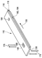
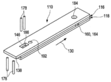
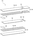
체액 내의 적어도 하나의 분석물을 전기 화학적으로 검출하기 위한 테스트 엘리먼트 (110) 가 개시된다. 테스트 엘리먼트 (110) 는 적어도 하나의 제 1 전극 (116) 및 적어도 하나의 제 2 전극 (118) 을 포함한다. 제 1 전극 (116) 은 작업 전극으로서 설계되고 제 2 전극은 카운터 전극으로서 설계된다. 테스트 엘리먼트 (110) 는 체액의 샘플을 수용할 수 있는 적어도 하나의 캐필러리 (160) 를 포함한다. 제 1 전극 (116) 및 제 2 전극 (118) 은 캐필러리 (160) 의 대향 사이드들 상에 배열된다. 제 1 전극 (116) 및 제 2 전극 (118) 은, 캐필러리 충진 동안 제 1 전극 (116) 및 제 2 전극 (118) 이 동시에 그리고 동일한 속도로 습윤되도록 배열된다.A test element 110 is disclosed for electrochemically detecting at least one analyte in a body fluid. The test element 110 includes at least one first electrode 116 and at least one second electrode 118. The first electrode 116 is designed as a working electrode and the second electrode is designed as a counter electrode. Test element 110 includes at least one capillary 160 that can receive a sample of a bodily fluid. The first electrode 116 and the second electrode 118 are arranged on opposite sides of the capillary 160. The first electrode 116 and the second electrode 118 are arranged such that the first electrode 116 and the second electrode 118 wet simultaneously and at the same rate during capillary filling.

Description
본 발명은 적어도 하나의 분석물 (analyte) 을 전기 화학적으로 검출하기 위한 테스트 엘리먼트, 이 테스트 엘리먼트를 제조하는 방법 및 샘플의 적어도 하나의 특성을 결정하기 위한 시스템을 개시한다. 본 발명에 따른 방법 및 디바이스들은 신체 조직 또는 체액 중 하나 또는 양자 모두에 존재하는 적어도 하나의 분석물을 검출하기 위해 사용될 수도 있고, 특히 이 방법 및 디바이스들은, 전문 진단 분야 및 가정 모니터링 분야 양자 모두에서, 혈액, 바람직하게는 전혈, 혈장, 혈청, 뇨, 타액, 간질액 또는 다른 체액들과 같은 체액들에서 글루코스, 락테이트, 트리글리세라이드들, 콜레스테롤 또는 다른 분석물들, 바람직하게는 대사물들과 같은 하나 이상의 분석물들을 검출하는 분야에 적용된다. 그러나, 다른 적용 분야들이 실행 가능하다.The present invention discloses a test element for electrochemically detecting at least one analyte, a method of making the test element, and a system for determining at least one property of a sample. The methods and devices according to the invention may be used for detecting at least one analyte present in one or both of body tissues or body fluids, in particular the methods and devices being used in both professional diagnostics and home monitoring. One such as glucose, lactate, triglycerides, cholesterol or other analytes, preferably metabolites in body fluids such as blood, preferably whole blood, plasma, serum, urine, saliva, interstitial fluid or other body fluids Applies to the field of detecting the above analytes. However, other applications are feasible.
의학 기술 및 진단 분야에서, 체액 내의 적어도 하나의 분석물을 검출하기 위한 다수의 디바이스들 및 방법들이 알려져 있다. 이 방법 및 디바이스들은, 혈액, 바람직하게는 전혈, 혈장, 혈청, 뇨, 타액, 간질액 또는 다른 체액들과 같은 체액들에서, 신체 조직 또는 체액 중 하나 또는 양자 모두에 존재하는 적어도 하나의 분석물, 특히 글루코스, 락테이트, 트리글리세라이드, 콜레스테롤 또는 다른 분석물들, 바람직하게는 대사물과 같은 하나 이상의 분석물들을 검출하기 위해 사용될 수도 있다. 활성화 시간들, 예를 들어 응고 모니터링을 위한 트롬빈 활성 시간을 측정하기 위한 추가의 디바이스들이 알려져 있다. 본 발명의 범위를 제한하지 않고, 다음에서는 예시적이고 바람직한 분석물로서 글루코스의 결정을 주로 참조한다.In the field of medical technology and diagnostics, a number of devices and methods are known for detecting at least one analyte in a body fluid. The methods and devices include at least one analyte present in one or both of body tissues or body fluids in body fluids such as blood, preferably whole blood, plasma, serum, urine, saliva, interstitial fluid or other body fluids. In particular, one or more analytes such as glucose, lactate, triglycerides, cholesterol or other analytes, preferably metabolites. Further devices are known for measuring activation times, eg thrombin activation time for coagulation monitoring. Without limiting the scope of the invention, the following mainly refers to the determination of glucose as an exemplary and preferred analyte.
혈당 농도 뿐만 아니라 대응하는 약물의 결정은 많은 당뇨병 환자에게 일상적으로 필수적인 부분이다. 편의성을 증가시키고, 허용 가능한 정도보다 많이 일상 생활을 제한하는 것을 회피하기 위해, 예컨대 작업, 여가 또는 집을 떠나 다른 활동들 동안 혈당 농도를 측정하기 위한 휴대용 디바이스들 및 테스트 엘리먼트들이 이 분야에 알려져 있다. 그 동안에, 많은 테스트 디바이스들이 상용 가능하다. 테스트 스트립들의 형태로 테스트 엘리먼트들의 사용에 기초하는 다수의 테스트 디바이스들 및 테스트 시스템들의 알려져 있다. 다수의 테스트 스트립들이 매거진에 의해 제공되고, 매거진으로부터의 테스트 스트립이 자동으로 테스팅 디바이스에 제공될 수도 있는 애플리케이션들이 알려져 있다. 그러나, 사용자에 의해 테스팅 디바이스 안으로 수동으로 삽입되는, 단일의 테스트 스트립들이 사용되는 다른 애플리케이션들이 알려져 있다. 통상적으로, 테스트 스트립의 단부는 테스팅 디바이스 안으로 삽입되고 분석물을 검출하기 위해 적응되고, 테스트 스트립의 대향 단부는 사용자가 테스트 스트립을 테스팅 디바이스 안으로 밀거나 또는 테스팅 디바이스로부터 테스트 스트립을 제거하게 할 수 있는 핸들로서 역할을 한다. 샘플을 테스트 엘리먼트에 공급하기 위해, 통상적인 테스트 엘리먼트는 캐필러리 테스트 엘리먼트의 캐필러리 개구 또는 상부 도징 시스템을 갖는 광학 테스트 스트립들의 스트라이프 망과 같은 적어도 하나의 샘플 적용 사이트를 제공한다. 이 유형의 테스트 스트립들은, 예를 들어 상품명 Accu-Chek Active® 하에서 상용 가능하다. 홈 케어 애플리케이션들 대신에, 이러한 테스트 엘리먼트들은 병원 애플리케이션들에서와 같은 전문적인 진단들에서 사용될 수도 있다.Determination of the corresponding drug, as well as blood sugar levels, is a routinely essential part of many diabetics. Portable devices and test elements are known in the art, for example, to measure blood glucose levels during work, leisure, or other activities away from home to increase convenience and avoid limiting daily life above an acceptable level. In the meantime, many test devices are commercially available. A number of test devices and test systems are known based on the use of test elements in the form of test strips. Applications are known in which multiple test strips are provided by a magazine and test strips from the magazine may be automatically provided to the testing device. However, other applications are known in which single test strips are used, which are manually inserted into the testing device by the user. Typically, the end of the test strip is inserted into the testing device and adapted to detect the analyte, and the opposite end of the test strip can allow the user to push the test strip into the testing device or to remove the test strip from the testing device. It serves as a handle. To supply the sample to the test element, a typical test element provides at least one sample application site, such as a stripe network of optical test strips having a capillary opening of the capillary test element or an upper dosing system. Test strips of this type are commercially available, for example under the trade name Accu-Chek Active®. Instead of home care applications, these test elements may be used in professional diagnostics, such as in hospital applications.
많은 경우들에서, 분석물을 검출하기 위해, 하나 이상의 테스트 화학물질들을 갖는 하나 이상의 테스트 필드들을 포함하는, 테스트 스트립들과 같은 테스트 엘리먼트들이 사용된다. 테스트 화학물질들은 검출될 분석물의 존재 시에 하나 이상의 검출 가능한 특성들을 변화시키도록 적응된다. 따라서, 테스트 화학물질의 전기 화학적으로 검출 가능한 특성들 및/또는 테스트 화학물질의 광학적으로 검출 가능한 특성들은 분석물의 존재의 영향으로 인해 변화될 수도 있다. 본 발명 내에서 사용될 수도 있는 잠재적인 테스트 화학물질에 대해서는, J. Hones 등: Diabetes Technology and Therapeutics, Vol.10, Supplement 1, 2008, S-10 내지 S-26 을 참조할 수 있다. 그러나, 테스트 화학물질들의 다른 유형들이 본 발명 내에서 사용될 수도 있다.In many cases, test elements, such as test strips, are used that include one or more test fields with one or more test chemicals to detect an analyte. Test chemicals are adapted to change one or more detectable properties in the presence of the analyte to be detected. Thus, the electrochemically detectable properties of the test chemical and / or the optically detectable properties of the test chemical may change due to the effect of the presence of the analyte. For potential test chemicals that may be used within the present invention, see J. Hones et al .: Diabetes Technology and Therapeutics, Vol. 10,
일반적으로, 적어도 하나의 분석물의 검출은 전기화학 테스트 엘리먼트를 사용함으로써 수행될 수 있다. 일반적으로, 일회용 전기화학 캐필러리 센서 테스트 엘리먼트들이 사용된다. 이러한 테스트 엘리먼트들은 통상적으로, 분석물을 검출하기 위한 적어도 하나의 작업 전극뿐만 아니라 테스트 엘리먼트의 측정 셀을 통과하는 전류를 지지하기 위한 적어도 하나의 카운터 전극을 포함한다. 또한, 옵션으로 테스트 엘리먼트는 적어도 하나의 레퍼런스 전극을 포함할 수도 있다. 대안의 실시형태들에서, 레퍼런스 전극은 개별적으로 설계될 수도 있고/있거나 카운터 전극과 결합될 수도 있다. 그러나, 전극 전위들의 비교로부터 분석물 농도를 도출하기 위해 다른 유형들의 측정 셋업들이 가능하다.In general, the detection of at least one analyte can be performed by using an electrochemical test element. Generally, disposable electrochemical capillary sensor test elements are used. Such test elements typically include at least one working electrode for detecting an analyte as well as at least one counter electrode for supporting a current passing through the test cell of the test element. In addition, the test element may optionally include at least one reference electrode. In alternative embodiments, the reference electrode may be designed separately and / or combined with the counter electrode. However, other types of measurement setups are possible to derive analyte concentration from a comparison of electrode potentials.
이러한 테스트 엘리먼트들은 통상적으로, 측정 셀을 포함한다. 측정 셀은 적어도 2 개의 전극 표면들, 특히 작업 전극과 카운터 전극 사이에 임베딩된 액체 샘플을 흡인하도록 구성된 캐필러리일 수도 있다. 적어도 2 개의 전극들 사이에 전압이 인가될 수도 있고, 응답 전류가 검출되어 적어도 하나의 분석물의 농도 값으로 변환된다. 통상적으로, 작업 전극으로 전기 회로를 폐쇄하기 위해 카운터 전극이 제공된다. 이 목적을 위해, 통상적으로 레독스 (redox) 전류들 및/또는 더 낮은 정도까지, 용량성 충전 전류들이 사용된다. 통상적으로, 작업 전극은 분석물과의 산화 반응 및/또는 레독스 반응을 수행하도록 적응된 적어도 하나의 검출기 물질을 포함한다. 많은 경우들에서, 검출기 물질은 글루코스 옥시다제 (GOD) 와 같은 적어도 하나의 효소를 포함한다. 검출 반응이 작업 전극에서 산화 반응을 포함하는 경우에서, 카운터 전극은 통상적으로 전기 회로를 폐쇄하기 위해 환원 반응을 제공한다.Such test elements typically include a measurement cell. The measuring cell may be a capillary configured to draw a liquid sample embedded between at least two electrode surfaces, in particular between the working electrode and the counter electrode. A voltage may be applied between the at least two electrodes and the response current is detected and converted into a concentration value of the at least one analyte. Typically, a counter electrode is provided to close the electrical circuit to the working electrode. For this purpose, capacitive charging currents are typically used to redox currents and / or to a lower extent. Typically, the working electrode comprises at least one detector material adapted to carry out an oxidation reaction and / or a redox reaction with the analyte. In many cases, the detector material comprises at least one enzyme, such as glucose oxidase (GOD). In the case where the detection reaction involves an oxidation reaction at the working electrode, the counter electrode typically provides a reduction reaction to close the electrical circuit.
구체적으로, 작업 전극은 적어도 하나의 시약 층에 의해 커버될 수도 있다. 종종 시약 층은 체액 내의 분석물의 특정 산화를 지원하도록 레독스 활성 효소 보조 인자를 갖는 효소를 포함할 수도 있다. 시약 층은 전자 억셉터로서 작용할 수도 있는 레독스 사이클 제공 물질을 더 포함할 수도 있다. 레독스 사이클 제공 물질은 효소 보조 인자와 반응할 수도 있고, 확산에 의해 효소 보조 인자로부터 취해진 전자들을 전극 표면으로 이송할 수도 있다. 전극 표면에서, 레독스 매개체가 산화될 수도 있고, 전달된 전자들은 전류로서 검출될 수도 있다. 전류는 체액 내의 분석물의 농도에 비례할 수도 있다. 액체 샘플을 측정 셀에 공급할 때, 시약이 용해될 수도 있고 전압을 인가함으로써 측정 프로세스가 시작될 수 있다. 전압은 일반적으로 테스트 스트립을 따라 전도성 트레이스들과 접속된 테스트 스트립의 일 단부에 배열된 전도성 접촉 패드들을 사용함으로써 전극들에 인가된다.In particular, the working electrode may be covered by at least one reagent layer. Often the reagent layer may include enzymes with redox active enzyme cofactors to support specific oxidation of analytes in body fluids. The reagent layer may further comprise a redox cycle providing material that may act as an electron acceptor. The redox cycle providing material may react with the enzyme cofactor and transfer electrons taken from the enzyme cofactor to the electrode surface by diffusion. At the electrode surface, the redox mediator may be oxidized and the transferred electrons may be detected as a current. The current may be proportional to the concentration of the analyte in the body fluid. When supplying a liquid sample to the measurement cell, the reagent may be dissolved and the measurement process may begin by applying a voltage. Voltage is generally applied to the electrodes by using conductive contact pads arranged at one end of the test strip connected with the conductive traces along the test strip.
WO 00/20626 에서는, 비-침출 또는 확산 레독스 매개체를 이용하는 센서가 설명된다. 이 센서는 작업 전극 및 카운터 전극을 포함하는 전극 쌍을 포함한다. 센서는 작업 전극 및 카운터 전극과 전해질 접촉하는 샘플 유체를 홀딩하기 위한 샘플 챔버를 포함한다. 샘플 챔버는 작업 전극 및 카운터 전극에 인접하여 포지셔닝된 측정 존을 포함한다. 분석물-반응 효소 및 확산가능 레독스 매개체가 측정 존에 배치된다.In WO 00/20626, sensors using non-leaching or diffusion redox mediators are described. The sensor includes an electrode pair that includes a working electrode and a counter electrode. The sensor includes a sample chamber for holding a sample fluid in electrolyte contact with a working electrode and a counter electrode. The sample chamber includes a measurement zone positioned adjacent to the working electrode and the counter electrode. Analyte-reacting enzymes and diffusible redox mediators are placed in the measurement zone.
일반적으로, 작업 전극은 혈당 테스트 엘리먼트, 예컨대 상품명 Accu-Chek Aviva® 또는 Performa® 하에서 상용 가능한 테스트 엘리먼트로서, 또는 예를 들어 상품명 CoaguChek® 하에서 상용 가능한 테스트 스트립들과 같은 테스트 엘리먼트들을 모니터링하는 응고물로서 설계될 수도 있다. 따라서, 플라스틱 포일은, 적어도 하나의 접촉, 전도성 트레이스들 및 전극 지지부들을 구축하는 적어도 하나의 전도성 층으로 커버될 수도 있는 테스트 캐리어로서 사용될 수도 있다. 전도성 층은 테스트 캐리어 상에 직접적으로 얇은 금속 필름으로서 스퍼터링될 수도 있고, 레이저 에칭 레이저 어블레이션 또는 리소그래피 중 하나 이상에 의해 구조화될 수도 있다. 대안으로, 구조물들은 스크린 또는 잉크젯 인쇄 프로세스에 의해 생성될 수도 있다. 시약 층은 코팅, 인쇄 또는 투여 중 하나 이상에 의해 테스트 캐리어에 공급될 수도 있다.In general, the working electrode is a blood glucose test element, for example a test element commercially available under the trade name Accu-Chek Aviva® or Performa®, or as a coagulum for monitoring test elements, for example test strips commercially available under the trade name CoaguChek®. It may be designed. Thus, the plastic foil may be used as a test carrier, which may be covered with at least one conductive layer that establishes at least one contact, conductive traces and electrode supports. The conductive layer may be sputtered as a thin metal film directly on the test carrier and may be structured by one or more of laser etching laser ablation or lithography. Alternatively, the structures may be created by a screen or ink jet printing process. The reagent layer may be supplied to the test carrier by one or more of coating, printing or dosing.
작업 전극은 금, 팔라듐, 백금과 같은 귀금속, 또는 흑연 또는 유리질 카본 형태의 카본 중 하나 이상일 수도 있다. 예를 들어, Accu-Chek Aviva® 또는 Performa®, 또는 CoaguChek® 의 테스트 스트립들에 금이 사용된다. 먼저, 금은 매우 고가의 재료이다. 또한, 카운터 전극은 심지어 환원 가능한 재료로 만들어질 수도 있다. 당해 기술에서, 예컨대 결합된 카운터 전극들/레퍼런스 전극들에 대해 Ag/AgCl 시스템들과 같은 레독스 재료들이 알려져 있다. 이 경우에서, 금 작업 전극 대 Ag/AgCl 전극의 이용 가능한 산화 전위는 약 700mV 에 제한되고, 금은 높은 전압에서 산화되어, 높은 예측할 수 없는 배경 전류를 야기할 수도 있다.The working electrode may be one or more of precious metals such as gold, palladium, platinum, or carbon in the form of graphite or glassy carbon. For example, gold is used in test strips of Accu-Chek Aviva® or Performa®, or CoaguChek®. First, gold is a very expensive material. In addition, the counter electrode may even be made of a reducible material. In the art, redox materials such as Ag / AgCl systems are known, for example for combined counter electrodes / reference electrodes. In this case, the available oxidation potential of the gold working electrode to Ag / AgCl electrode is limited to about 700 mV, and gold may be oxidized at high voltage, resulting in a high unpredictable background current.
금을 대신하여, 흑연 전극들이 사용될 수도 있다. 흑연은 코팅 프로세스를 허용하는 유기 성분들을 또한 포함하는, 페이스트 또는 잉크로서 사용될 수도 있다. 두꺼운 흑연 필름들은 스크린 인쇄 또는 유사한 프로세스에 의해 구조화될 수도 있다. 그러나, 인쇄된 흑연 전극 표면들은 상대적으로 높은 허용 오차를 가질 수도 있고, 스퍼터링된, 레이저 제거된 금 전극에 비해 더 높은 부정확도를 야기할 수도 있다. 이러한 전극 구조화 프로세서들에서 생산된 전극들을 갖는 모든 유형들의 테스트 엘리먼트들은 라미네이션 프로세스들에서 정확한 포지셔닝을 필요로 하고, 여기서 구조화된 테스트 캐리어 및 캐필러리 구조가 어셈블링된다. 따라서, 이러한 테스트 스트립의 제조 프로세스는 복잡하고, 고가이며 유연하지 않을 수도 있다. 또한, 테스트 엘리먼트들의 치수들과 같은 테스트 엘리먼트들의 구조들은 고정되고, 테스트 스트립의 변형들을 생성하기 위해 쉽게 변경될 수 없다.Instead of gold, graphite electrodes may be used. Graphite may be used as a paste or ink, which also includes organic components that allow the coating process. Thick graphite films may be structured by screen printing or similar processes. However, printed graphite electrode surfaces may have a relatively high tolerance and may cause higher inaccuracies compared to sputtered, laser removed gold electrodes. All types of test elements with electrodes produced in such electrode structuring processors require accurate positioning in lamination processes, where the structured test carrier and capillary structure is assembled. Thus, the manufacturing process of such test strips may be complicated, expensive and inflexible. In addition, the structures of the test elements, such as the dimensions of the test elements, are fixed and cannot be easily changed to produce deformations of the test strip.
일반적으로 사용된 테스트 엘리먼트들에서, 전극들은 동일평면 구성으로 배열될 수도 있다. 제조 비용들 및 프로세스 복잡성으로 인해, 하나의 생산 프로세스 동안, 예컨대 하나의 라미네이션 프로세스 동안 전극들을 생산하는 것이 바람직할 수도 있다. 체액의 샘플들은, 예를 들어 셀프-테스팅 또는 홈 케어 애플리케이션에서 사용자에 의해 손가락 끝을 찌름으로써 취해질 수도 있다. 이들 샘플들은 2㎕ 보다 더 작은 체적들과 같은 작은 체적들을 가질 수도 있다. 따라서, 이들 샘플들에 적합한 캐필러리 체적은, 생산 상의 이유들로 하나의 라미네이션 프로세스에서 동일한 시약 스트라이프로 적어도 2 개의 동일 평면상의 전극들을 코팅하는 것이 가능할 수 있도록, 작아야 한다. 따라서, 시약 중의 활성 성분들은 작업 전극에서의 분석 검출 반응을 지원할 뿐만 아니라, 또한 카운터 전극상의 전극 반응들을 지원해야 한다. 그러나, 이것은 사용 가능한 화학 옵션에 대한 제한을 설정할 수 있다: 시약은, 최대 7 일까지 지속될 수도 있는 코팅 프로세스 동안 액체로 안정해야 하고; 시약은 샘플의 레독스 활성 물질을 방해해서는 안 되며; 제한된 카운터 전극 반응에 의해 작업 전극 전류가 컷 오프되지 않아야 한다.In generally used test elements, the electrodes may be arranged in a coplanar configuration. Due to manufacturing costs and process complexity, it may be desirable to produce the electrodes during one production process, such as during one lamination process. Samples of body fluids may be taken, for example, by pricking the fingertip by the user in a self-testing or home care application. These samples may have small volumes, such as volumes smaller than 2 μl. Thus, the capillary volume suitable for these samples should be small so that for production reasons it may be possible to coat at least two coplanar electrodes with the same reagent stripe in one lamination process. Thus, the active ingredients in the reagents must not only support the assay detection reaction at the working electrode, but also support the electrode reactions on the counter electrode. However, this may set a limit on the chemical options available: the reagents must be stable with the liquid during the coating process, which may last up to 7 days; Reagents should not interfere with the redox active material of the sample; The working electrode current should not be cut off by the limited counter electrode reaction.
원리적으로, 동일평면 구성에 대한 대안의 구성들이 알려져 있다. US 2004/0118705 A1 은, 얇은 스페이서 층에 의해 분리된 대향하는 금속 전극들에 의해 정의된 복수의 반응 존들을 갖는 전기화학 테스트 스트립들을 설명한다. 전기화학 테스트 스트립은 상기 반응 존들 각각에 존재하는 시약 조성물을 포함한다. EP 0964059 B1 은, 작업 전극 베이스 플레이트, 카운터 전극 베이스 플레이트, 적어도 하나의 효소를 함유하는 시약 층 및 전자 매개체를 포함하는 바이오센서를 개시한다. 작업 전극은 상기 작업 전극 베이스 플레이트 상에 배치되고 카운터 전극은 상기 카운터 전극 베이스 플레이트 상에 배치된다. 상기 작업 전극 및 상기 카운터 전극은, 전극들 사이에 공간을 갖고 서로 상호적으로 대면하도록 포지셔닝된다.In principle, alternative configurations for coplanar configurations are known. US 2004/0118705 A1 describes electrochemical test strips having a plurality of reaction zones defined by opposing metal electrodes separated by a thin spacer layer. The electrochemical test strip comprises a reagent composition present in each of the reaction zones. EP 0964059 B1 discloses a biosensor comprising a working electrode base plate, a counter electrode base plate, a reagent layer containing at least one enzyme and an electron mediator. A working electrode is disposed on the working electrode base plate and a counter electrode is disposed on the counter electrode base plate. The working electrode and the counter electrode are positioned to face each other with a space between the electrodes.
WO 2009/053834 A1 에서, 대향하는 전극들을 갖는 센서 및 이 센서를 사용한 테스트 스트립들이 설명된다. 센서는 작업 전극, 카운터 전극 및 전기화학 기판을 포함하고, 이 센서는 전기화학 기판의 분열 (cleavage) 을 검출한다. WO01/57238 A1 에서, 스페이서에 의해 분리된 대향하는 작업 및 레퍼런스 전극들을 에 의해 정의된 반응 존을 포함하는 전기화학 테스트 스트립이 개시된다. 레독스 시약 시스템이 상기 반응 존에 존재하고, 상기 레독스 시약 시스템은 적어도 하나의 효소 및 매개체를 포함한다.In WO 2009/053834 A1 a sensor with opposing electrodes and test strips using the sensor are described. The sensor comprises a working electrode, a counter electrode and an electrochemical substrate, which detects cleavage of the electrochemical substrate. In WO01 / 57238 A1 an electrochemical test strip is disclosed which comprises a reaction zone defined by opposing working and reference electrodes separated by a spacer. A redox reagent system is present in the reaction zone and the redox reagent system comprises at least one enzyme and mediator.
대향 전극 구성은 작업 및 카운터 전극이 별개의 시약들로 코팅되는 것을 허용한다. 예를 들어, 카운터 전극은 Ag/AgCl 페이스트로 코팅될 수도 있다. 그러나, 대향 전극 구성들을 갖는 알려진 디바이스들은 단점을 드러낸다. 특히, 전극들의 제조 프로세스의 코팅 및 건조 프로세스들은 함께 수행될 수 없고, 병행 또는 별개의 프로세스 단계들로 수행되어야 한다. 따라서, 제조 프로세스는 복잡하고 따라서 고가일 수도 있다. 또한, 캐필러리의 달성 가능한 체적은 하나의 시약 스트라이프를 갖는 스트립 설계들과 비교하여 더 클 수도 있다. 대향 전극들의 이러한 제조 프로세스는 US 5,437,999 에서 설명된다. 상기 문헌은, 매우 작은 샘플 크기에서 정확한 분석물 농도를 결정할 수 있는 전기화학 센서의 생산을 가능하게 하는 고-해상도의 생체 적합성 전극을 제조하는 방법을 개시한다. 전기 전도성 재료가 제 1 절연 기판에 고정된다. 그 다음, 제 2 절연 기판이 전기 전도성 재료에 부착되고 포토 리소그래피를 사용하여 패턴화되어 전극 영역을 정의한다. 전극은 기판 재료의 별개의 피스들 상에 제조되고, 따라서 2 개의 전극들의 제조 프로세스들이 분리되어, 작업 전극 및 카운터 전극과 연관된 화학물질들의 분리를 허용한다는 것이 요약되어 있다.The counter electrode configuration allows the working and counter electrodes to be coated with separate reagents. For example, the counter electrode may be coated with Ag / AgCl paste. However, known devices with opposing electrode configurations present a disadvantage. In particular, the coating and drying processes of the manufacturing process of the electrodes cannot be carried out together and must be carried out in parallel or in separate process steps. Thus, the manufacturing process may be complex and therefore expensive. In addition, the achievable volume of the capillary may be larger compared to strip designs with one reagent stripe. This manufacturing process of the counter electrodes is described in US 5,437,999. This document discloses a method of making high-resolution biocompatible electrodes that enable the production of electrochemical sensors capable of determining accurate analyte concentrations at very small sample sizes. An electrically conductive material is secured to the first insulating substrate. A second insulating substrate is then attached to the electrically conductive material and patterned using photolithography to define the electrode region. It is summarized that the electrode is fabricated on separate pieces of substrate material, so that the manufacturing processes of the two electrodes are separated, allowing separation of the chemicals associated with the working electrode and the counter electrode.
또한, 위에서 요약된 바와 같이, 요구된 전극 형상 및/또는 알려진 전극들의 구조가 불리할 수도 있다. A. Heller 와 B. Feldman: Electrochemistry in Diabetes Management, Accounts of chemical research, vol 43, No 7, July 2010, 963-973 에서, 대향 전극 구성을 갖는 테스트 스트립이 도시된다. 그러나, 설명된 테스트 스트립은 특정 전극 구조를 갖는 전극들을 요구한다. 따라서, 정확한 포지셔닝이 요구되고, 따라서 제조 프로세스는 복잡하고 고가일 수도 있다.In addition, as summarized above, the required electrode shape and / or the structure of known electrodes may be disadvantageous. In A. Heller and B. Feldman: Electrochemistry in Diabetes Management, Accounts of chemical research, vol 43, No 7, July 2010, 963-973, test strips with counter electrode configurations are shown. However, the described test strip requires electrodes with a specific electrode structure. Therefore, accurate positioning is required, and thus the manufacturing process may be complicated and expensive.
US 2007/068807 A1 에서, 샘플 내의 분석물의 농도를 결정하기 위한 캔틸레버된 (cantilevered) 분석물 센서가 설명된다. 이 센서는 센서의 샘플 수용 단부에 오버행 기판 벽을 갖는 샘플 챔버를 포함한다.In US 2007/068807 A1 a cantilevered analyte sensor for determining the concentration of an analyte in a sample is described. The sensor includes a sample chamber having an overhang substrate wall at the sample receiving end of the sensor.
문헌 US 2014/174947 A1 은 샘플-수용 챔버를 한정하도록 배열된 상호 절연된 제 1 및 제 2 전극들을 갖는 분석 테스트 스트립을 설명한다. 전기적 절연층들이 개별의 전극들 위에 배치된다. 제 1 및 제 2 전기 접촉 패드들은 제 1 전극에 전기적으로 접속되고, 제 3 패드는 제 2 전극에 전기적으로 접속된다. 테스트 스트립의 제 1 사이드는 제 1 전기 절연층 및 제 3 패드를 갖고, 제 2 사이드는 제 2 전기 절연층과 제 1 및 제 2 패드들을 갖는다. 제 3 패드는 샘플 수용 챔버로부터 제 1 전기 절연층보다 더 멀리 길이방향으로 연장된다. 또한, 체액의 샘플 내의 분석물을 결정하는 방법들 및 분석 테스트 시스템들이 설명된다.Document US 2014/174947 A1 describes an analytical test strip having mutually insulated first and second electrodes arranged to define a sample-receiving chamber. Electrically insulating layers are disposed over the individual electrodes. The first and second electrical contact pads are electrically connected to the first electrode, and the third pad is electrically connected to the second electrode. The first side of the test strip has a first electrically insulating layer and a third pad, and the second side has a second electrically insulating layer and first and second pads. The third pad extends longitudinally further from the sample receiving chamber than the first electrically insulating layer. Also described are methods and analytical test systems for determining analytes in a sample of bodily fluid.
EP 1 253 204 A2 에서, 전극지지 기판, 전극지지 기판 상에 위치된 전극들, 전극지지 기판에 연결된 센서 지지 기판 및 센서 지지 기판 상에 위치된 전기 전도성 트랙들을 포함하는 바이오 센서가 개시된다. 각각의 트랙은 전극들 중 하나와 전기 통신한다.In
US 2013/026050 A1 은, 특정 기질로서 분석물을 산화시켜 비활성 환원된 형태의 효소를 생성하는 활성 레독스 효소를 포함하는 건조 시약 조성물을 설명한다. 또한, 스트립 구조의 일 부분에 제 1 전극 및 스트립 구조의 제 2 부분에 제 2 전극, 스트립을 조립함으로써 형성된 액체 샘플을 수용하기 위한 샘플 셀을 포함하는 테스트 스트립이 개시되며, 샘플 셀 내에 배치된 액체 샘플은 제 1 및 제 2 전극들, 전극들에 전기적 접촉하는 것을 허용하는 노출된 표면들, 및 조립 전에 노출된 전극 상에 디포짓된 건조 시약과 접촉된다.US 2013/026050 A1 describes a dry reagent composition comprising an active redox enzyme that oxidizes analyte as a specific substrate to produce an enzyme in an inactive reduced form. Also disclosed is a test strip comprising a first electrode on a portion of a strip structure and a second electrode on a second portion of the strip structure, a sample cell for receiving a liquid sample formed by assembling the strip, the test strip being disposed within the sample cell. The liquid sample is contacted with the first and second electrodes, exposed surfaces allowing electrical contact to the electrodes, and a drying reagent deposited on the exposed electrode prior to assembly.
US 2005/214171 A1 에서, 액체 샘플들을 샘플링하기 위한 디바이스가 설명된다. 이 디바이스는 캐필러리-활성 채널, 샘플링 사이트, 및 결정 사이트를 포함한다. 캐필러리-활성 채널은 샘플을 샘플링 사이트로부터 결정 사이트로 운송하기 위해 구성된다. 캐필러리-활성 채널은 실질적으로, 캐리어, 커버 및 캐리어와 커버 사이에 위치된 중간 층에 의해 형성된다. 캐리어는 샘플링 사이트의 영역에서 커버 위로 돌출한다. 중간층은 샘플링 사이트의 영역에서 결정 사이트의 방향으로 뒤쪽을 향해 변위되므로, 이 캐리어 뿐만 아니라 커버는 중간 층을 넘어 돌출한다. 디바이스는 샘플이 샘플링 사이트의 영역에서 캐리어의 노출된 영역에 위에서부터 공급되는 것을 허용하고, 또한 샘플이 사이드로부터 공급되는 것을 허용한다.In US 2005/214171 A1 a device for sampling liquid samples is described. The device includes a capillary-active channel, a sampling site, and a decision site. The capillary-active channel is configured to transport the sample from the sampling site to the decision site. The capillary-active channel is formed substantially by the carrier, the cover and the intermediate layer located between the carrier and the cover. The carrier protrudes over the cover in the region of the sampling site. Since the intermediate layer is displaced backwards in the direction of the crystal site in the region of the sampling site, the cover as well as the carrier protrudes beyond the intermediate layer. The device allows the sample to be fed from above to the exposed area of the carrier in the region of the sampling site and also to allow the sample to be fed from the side.
US 2005/279647 A1 은 생물학적 유체 내의 관심있는 분석물의 농도를 측정하기 위한 테스트 스트립을 설명하며, 테스트 스트립은 테스트 스트립이 삽입되는 테스트 미터에 의해 판독될 수 있는 정보로 인코딩될 수도 있다. 홈 케어 및/또는 셀프-테스팅 애플리케이션들에 대해 알려진 테스트 엘리먼트들은 캐필러리 안으로 샘플을 투여 또는 공급하기 위한 프론트 도징 또는 사이드 도징 포지션을 가질 수도 있다. 위에서 요약된 바와 같이, 체액의 샘플은 손가락 끝을 찌름으로써 취해질 수도 있다. 일반적으로, 캐필러리 개구들은 테스트 엘리먼트의 프론트 에지 또는 사이드 에지 상에 배열될 수도 있다. 그러나, 병원과 같이 전문적인 장소들에서의 사용을 위해, 전체 테스팅의 상당 부분이 샘플 튜브들로부터 취해진 정맥 또는 동맥혈에서 나올 수 있으므로, 피펫들, 유리 캐필러리들 또는 주사기들과 같은 트랜스퍼 디바이스들이 샘플의 투여 또는 공급을 위해 사용되어야 한다. 따라서, 프론트 에지 또는 사이드 에지 상의 캐필러리 개구들은 이들 트랜스퍼 디바이스들로 핸들링하기가 편리하지 않고 어려울 수도 있다.US 2005/279647 A1 describes test strips for measuring the concentration of an analyte of interest in a biological fluid, which may be encoded into information that can be read by a test meter into which the test strip is inserted. Test elements known for home care and / or self-testing applications may have a front or side dosing position for administering or supplying a sample into the capillary. As summarized above, a sample of body fluid may be taken by pricking the fingertip. In general, the capillary openings may be arranged on the front edge or side edge of the test element. However, for use in professional places such as hospitals, transfer devices such as pipettes, glass capillaries or syringes may be used because a significant portion of the total testing may come from venous or arterial blood taken from the sample tubes. Should be used for the administration or supply of Thus, capillary openings on the front edge or side edge may not be convenient and difficult to handle with these transfer devices.
따라서, 본 발명의 목적은 전체 제조 프로세스에서 요구된 어떤 포지셔닝 의존 정렬 없이도 용이하고 비용 효율적인 프로세스로 제조될 수 있는 테스트 엘리먼트를 제공하는 것이다. 또한, 테스트 엘리먼트들로의 샘플 투여는 홈 케어 및 전문적인 진단 애플리케이션들 양자 모두에서 핸들링하기 편리하고 쉬워야 할 것이다.It is therefore an object of the present invention to provide a test element that can be manufactured in an easy and cost effective process without any positioning dependent alignment required in the entire manufacturing process. In addition, sample administration to test elements should be convenient and easy to handle in both home care and professional diagnostic applications.
이 문제는 적어도 하나의 분석물을 전기 화학적으로 검출하기 위한 테스트 엘리먼트, 테스트 엘리먼트를 생산하는 방법 및 독립항들의 특징들을 갖는 샘플의 적어도 하나의 특성을 결정하기 위한 시스템에 의해 해결된다. 분리된 방식으로 또는 임의의 조합으로 실현될 수도 있는 바람직한 실시형태들은 종속 항들에 열거된다.This problem is solved by a system for determining at least one characteristic of a sample having the features of the test elements, a method of producing the test element, and the independent claims for electrochemically detecting at least one analyte. Preferred embodiments which may be realized in a separate manner or in any combination are listed in the dependent claims.
다음에서 사용된 바와 같이, 용어들 "갖는" 또는 "포함하는" 또는 임의의 그 문법적인 변형들은 비-배타적인 방식으로 사용된다. 따라서, 이들 용어는 이들 용어들에 의해 도입된 특징 이외에, 이 문맥에서 설명된 엔티티에 추가의 특징이 존재하지 않는 상황 및 하나 이상의 추가의 특징들이 존재하는 상황 양자 모두를 지칭할 수도 있다. 일 예로서, 표현들 "A 는 B 를 갖는다", "A 는 B 를 포함한다" 및 "A 는 B 를 포함한다" 양자 모두는, B 이외에, 다른 엘리먼트가 A 에 존재하지 않는 상황 (즉, A가 유일하게 그리고 배타적으로 B 로 이루어진 상황) 및, B 이외에 하나 이상의 추가의 엘리먼트들, 예컨대 엘리먼트 C, 엘리먼트들 C 및 D 또는 심지어 추가의 엘리먼트들이 엔티티 A 에 존재하는 상황을 지칭할 수도 있다.As used in the following, the terms “having” or “comprising” or any of its grammatical variations are used in a non-exclusive manner. Thus, these terms may refer to both situations in which, in addition to the features introduced by these terms, there are no additional features in the entity described in this context, and situations in which one or more additional features are present. As one example, the expressions “A has B”, “A contains B” and “A contains B” both refer to a situation in which no other element is present in A other than B (ie, A situation in which A consists solely and exclusively of B) and one or more additional elements other than B, such as element C, elements C and D or even additional elements may be present in entity A.
또한, 이하에서 사용되는 바와 같이, 용어들 "바람직하게", "더 바람직하게", "특히", "보다 특히", "구체적으로", "보다 구체적으로" 또는 유사한 용어들은 대안의 가능성들을 제한하지 않고, 선택적 특징들과 결합되어 사용된다. 따라서, 이들 용어들에 의해 도입된 특징들은 선택적 특징들이고 청구항들의 범위를 임의의 방식으로 제한하도록 의도되지 않는다. 당업자가 인식할 수 있는 바와 같이, 본 발명은 대안의 특징들을 사용함으로써 수행될 수도 있다. 유사하게, "본 발명의 실시형태에서" 또는 유사한 표현들에 의해 도입된 특징들은 본 발명의 범위에 관한 임의의 제한들 없이, 그리고 이러한 방식으로 도입된 특징들을 본 발명의 다른 선택적인 또는 비-선택적 특징들과 결합하는 가능성에 관한 임의의 제한 없이 선택적 특징들인 것으로 의도된다.Also, as used below, the terms "preferably", "more preferably", "particularly", "more particularly", "specifically", "more specifically" or similar terms limit alternative possibilities. Rather, it is used in conjunction with optional features. Accordingly, the features introduced by these terms are optional features and are not intended to limit the scope of the claims in any way. As will be appreciated by those skilled in the art, the invention may be practiced by using alternative features. Similarly, features introduced by "in an embodiment of the present invention" or by similar expressions may be incorporated without other limitations of the scope of the present invention and other optional or non-current features of the present invention. It is intended to be optional features without any limitation as to the possibility of combining with optional features.
본 발명의 제 1 양태에서, 체액 상에서 적어도 하나의 분석물을 전기 화학적으로 검출하기 위한 테스트 엘리먼트가 개시된다. 본원에 추가로 사용된 바와 같이, 용어 "분석물" 은 사용자 또는 환자에게 관심 있을 수도 있는 농도 및 체액에 존재할 수도 있는 임의의 엘리먼트, 컴포넌트 또는 화합물을 지칭할 수도 있다. 바람직하게는, 분석물은 적어도 하나의 대사물과 같은 환자의 신진 대사에 참여할 수도 있는 임의의 화학 물질 또는 화학적 화합물일 수도 있거나 이를 포함할 수도 있다. 일 예로서, 적어도 하나의 분석물은 글루코스, 콜레스테롤, 트리글리세라이드들, 락테이트로 이루어진 군으로부터 선택될 수도 있다. 그러나, 부가적으로 또는 대안으로, 다른 유형들의 분석물들이 사용될 수도 있고/있거나 분석물들의 임의의 조합이 결정될 수도 있다. 일반적으로, 임의의 유형의 체액이 사용될 수도 있다. 본 발명에서 일반적으로 사용되는 바와 같이, 용어 "환자" 는, 인간 또는 동물이 각각 건강한 상태에 있거나 또는 하나 이상의 질병을 앓고 있다는 사실과 무관하게 인간 또는 동물을 지칭할 수도 있다. 일 예로서, 환자는 당뇨병을 앓고 있는 인간이거나 동물일 수도 있다. 그러나, 부가적으로 또는 대안으로, 본 발명은 다른 유형들의 사용자들 또는 환자들에게 적용될 수도 있다.In a first aspect of the invention, a test element for electrochemically detecting at least one analyte on a body fluid is disclosed. As further used herein, the term “analyte” may refer to any element, component or compound that may be present in a body fluid and at a concentration that may be of interest to a user or patient. Preferably, the analyte may be or include any chemical or chemical compound that may participate in metabolism of the patient, such as at least one metabolite. As one example, the at least one analyte may be selected from the group consisting of glucose, cholesterol, triglycerides, lactate. However, additionally or alternatively, other types of analytes may be used and / or any combination of the analytes may be determined. In general, any type of body fluid may be used. As used generally in the present invention, the term “patient” may refer to a human or an animal regardless of the fact that each human or animal is in a healthy state or suffers from one or more diseases. In one example, the patient may be a human or animal suffering from diabetes. However, in addition or alternatively, the present invention may be applied to other types of users or patients.
체액은 간질 조직과 같은 환자의 신체 조직에 존재하는 체액일 수도 있다. 따라서, 일 예로서, 체액은 혈액 및 간질액으로 이루어진 군으로부터 선택될 수도 있다. 그러나, 부가적으로 또는 대안으로, 하나 이상의 다른 유형들의 체액들이 사용될 수도 있다. 체액은 일반적으로, 신체 조직에 포함될 수도 있다.Body fluid may be a body fluid present in the body tissue of a patient, such as interstitial tissue. Thus, as an example, the body fluid may be selected from the group consisting of blood and interstitial fluid. Additionally or alternatively, however, one or more other types of body fluids may be used. Body fluids may generally be included in body tissues.
본원에 사용된 바와 같이, 용어 "테스트 엘리먼트" 는, 바람직하게는 분석물이 테스트 화학물질, 예컨대 위에 열거된 종래 기술에서 개시된 테스트 화학물질들 중 하나 이상과 같은 체액에 존재하는 경우, 적어도 하나의 검출 가능한 특성을 변화시키는 적어도 하나의 컴포넌트를 포함함으로써, 체액 내의 분석물을 검출할 수 있는 임의의 디바이스를 지칭한다. 용어 "테스트 화학물질" 은 적어도 하나의 분석물의 존재에서 적어도 하나의 검출 가능한 특성을 변화시키도록 적응된 재료들의 조성물 또는 임의의 재료를 지칭한다. 일반적으로, 이 특성은 전기 화학적으로 검출 가능한 특성 및/또는 광학적으로 검출 가능한 특성, 예컨대 컬러 변화 및/또는 경감하는 특성들에서의 변화로부터 선택될 수도 있다. 잠재적인 화학물질들에 대해, 전술된 종래 기술을 참조할 수도 있다. 구체적으로, 적어도 하나의 테스트 화학물질은 테스트 엘리먼트에 공급된 체액의 샘플에 분석물이 존재하는 경우에만 특성을 변화시키는 반면에, 분석물이 존재하지 않는 경우 변화가 발생하지 않는 고도로 선택적인 테스트 화학물질일 수도 있다. 보다 바람직하게, 적어도 하나의 특성의 정도 또는 변화는 분석물의 정량적 검출을 허용하기 위해서, 체액 내의 분석물의 농도에 의존한다. 일 예로서, 테스트 화학물질은 글루코스 옥시다제 및/또는 글루코스 탈수소효소와 같은 적어도 하나의 효소를 포함할 수도 있다. 부가적으로 또는 대안으로, 테스트 화학물질은 하나 이상의 조효소 (co-enzyme) 및/또는 하나 이상의 매개체들을 포함할 수도 있다. 또한, 대안으로 또는 부가적으로, 테스트 화학물질은 하나 이상의 염료들을 포함할 수도 있고, 이것은 바람직하게는 하나 이상의 효소들과의 상호 작용에서, 검출될 적어도 하나의 분석물의 존재에서 그들의 컬러를 변화시킬 수도 있다. 추가의 잠재적인 실시형태들에 대해, 전술된 종래 기술의 문헌들을 참조할 수도 있다. 본원에 사용된 바와 같이, 용어 "전기 화학적으로 검출" 은 전기 화학적 검출 반응과 같은, 분석물의 전기 화학적으로 검출 가능한 특성의 검출을 지칭한다. 따라서, 예를 들어, 전기 화학적 검출 반응은 작업 전극의 정전 전위와 같은 하나 이상의 전극 전위들을 카운터 전극 또는 레퍼런스 전극과 같은 하나 이상의 추가의 전극들의 정전 전위와 비교함으로써 검출될 수도 있다. 이 검출은 분석물 특정적일 수도 있다. 검출은 정성 및/또는 정량적 검출일 수도 있다. 테스트 엘리먼트는 스트립-형 테스트 엘리먼트일 수도 있다. 본원에 사용된 바와 같이, 용어 "스트립-형" 은 긴 형상 및 두께를 갖는 엘리먼트를 지칭하고, 측방 치수에서 엘리먼트의 연장은 그 엘리먼트의 두께를, 예컨대 적어도 2 배만큼, 바람직하게는 적어도 5 배, 보다 바람직하게는 적어도 10 배, 및 가장 바람직하게는 적어도 20 배 또는 심지어 적어도 30 배만큼 초과한다. 테스트 엘리먼트는 테스트 스트립일 수도 있다.As used herein, the term “test element” preferably refers to at least one when the analyte is present in a body fluid such as a test chemical, such as one or more of the test chemicals disclosed in the prior art listed above. By including at least one component that changes the detectable property, it refers to any device capable of detecting an analyte in a bodily fluid. The term “test chemical” refers to any material or composition of materials that is adapted to change at least one detectable property in the presence of at least one analyte. In general, this property may be selected from electrochemically detectable properties and / or optically detectable properties such as color changes and / or changes in mitigating properties. For potential chemicals, reference may be made to the prior art described above. Specifically, the at least one test chemical only changes properties when the analyte is present in the sample of bodily fluid supplied to the test element, whereas the highly selective test chemistry does not occur when no analyte is present. It may be a substance. More preferably, the degree or change of at least one property depends on the concentration of the analyte in the body fluid to allow for quantitative detection of the analyte. As an example, the test chemical may include at least one enzyme, such as glucose oxidase and / or glucose dehydrogenase. Additionally or alternatively, the test chemical may include one or more co-enzymes and / or one or more mediators. Alternatively or additionally, the test chemicals may also comprise one or more dyes, which preferably change their color in the presence of at least one analyte to be detected, in interaction with one or more enzymes. It may be. For further potential embodiments, reference may be made to the prior art documents described above. As used herein, the term “electrochemically detecting” refers to the detection of electrochemically detectable properties of an analyte, such as an electrochemical detection reaction. Thus, for example, an electrochemical detection reaction may be detected by comparing one or more electrode potentials, such as the electrostatic potential of the working electrode, with the electrostatic potential of one or more additional electrodes, such as a counter electrode or a reference electrode. This detection may be analyte specific. Detection may be qualitative and / or quantitative detection. The test element may be a strip-type test element. As used herein, the term “strip-shaped” refers to an element having an elongated shape and thickness, wherein the extension of the element in the lateral dimension increases the thickness of the element, such as at least two times, preferably at least five times. , More preferably at least 10 times, and most preferably at least 20 times or even at least 30 times. The test element may be a test strip.
테스트 엘리먼트는 적어도 하나의 제 1 전극 및 적어도 하나의 제 2 전극을 포함한다. 제 1 전극은 작업 전극으로서 설계되고, 제 2 전극은 카운터 전극으로서 설계된다. 본원에 사용된 바와 같이, 용어 "전극" 은 직접 또는 적어도 하나의 반투과성 막 또는 층을 통해 체액과 접촉하게 되도록 적응되는 테스트 엘리먼트의 엔티티를 지칭한다. 각각의 전극은, 전기 화학적 반응이 이 전극에서 발생할 수도 있도록 구현될 수도 있다. 따라서, 전극들은 산화 반응 및/또는 환원 반응이 이 전극들에서 발생할 수도 있도록 구현될 수도 있다. 본원에 사용된 바와 같이, 용어 "작업 전극" 은 체액 내의 적어도 하나의 분석물을 검출하기 위해 적어도 하나의 전기 화학적 검출 반응을 수행하기 위해 적응되는 전극을 지칭한다. 따라서, 작업 전극은 적어도 하나의 시약, 예컨대 하나의 테스트 화학물질을 포함할 수도 있다. 본원에 사용된 바와 같이, 용어 "카운터 전극" 은 작업 전극에서 검출 반응에 의해 요구된 전류 흐름의 균형을 맞추기 위해 적응된 적어도 하나의 전기 화학적 카운터 반응을 수행하기 위해 적응된 전극을 지칭한다. 테스트 엘리먼트는 적어도 하나의 레퍼런스 전극, 예를 들어 결합된 카운터 전극/레퍼런스 전극 시스템을 더 포함할 수도 있다. 본원에 사용된 바와 같이, 용어 작업 전극은 체액 내의 적어도 하나의 분석물을 검출하기 위한 적어도 하나의 전기 화학적 검출 반응을 수행하기 위해 적응되는 전극을 지칭한다.The test element comprises at least one first electrode and at least one second electrode. The first electrode is designed as a working electrode and the second electrode is designed as a counter electrode. As used herein, the term “electrode” refers to an entity of a test element that is adapted to come into contact with body fluids directly or through at least one semipermeable membrane or layer. Each electrode may be implemented such that an electrochemical reaction may occur at this electrode. Thus, the electrodes may be implemented such that an oxidation reaction and / or a reduction reaction may occur at these electrodes. As used herein, the term “working electrode” refers to an electrode that is adapted to perform at least one electrochemical detection reaction to detect at least one analyte in a body fluid. Thus, the working electrode may comprise at least one reagent, such as one test chemical. As used herein, the term “counter electrode” refers to an electrode that is adapted to perform at least one electrochemical counter reaction adapted to balance the current flow required by the detection reaction at the working electrode. The test element may further comprise at least one reference electrode, for example a combined counter electrode / reference electrode system. As used herein, the term working electrode refers to an electrode that is adapted to perform at least one electrochemical detection reaction to detect at least one analyte in a body fluid.
제 1 전극 및 제 2 전극은 동일한 치수를 가질 수도 있다. 용어 "치수" 는 제 1 및 제 2 전극들의 폭, 길이, 표면적, 형상 중 하나 이상을 지칭한다. 특히, 제 1 및 제 2 전극들은 인렛들, 노치들 등과 같은 구조들이 없는 형상과 같은 비-구조화된 전극 형상으로 설계될 수도 있다. 전극들의 형상은 제조 프로세스, 예컨대 커팅 프로세스에 의해 결정될 수도 있다. 따라서, 형상은 본질적으로 직사각형 일 수도 있고, 용어 "본질적으로 직사각형" 은 제조 허용 오차들 내에서 직사각형 형상으로부터의 편차들이 가능하다는 것을 지칭한다.The first electrode and the second electrode may have the same dimension. The term "dimension" refers to one or more of the width, length, surface area, shape of the first and second electrodes. In particular, the first and second electrodes may be designed in a non-structured electrode shape, such as a shape without structures such as inlets, notches, and the like. The shape of the electrodes may be determined by a manufacturing process, such as a cutting process. Thus, the shape may be essentially rectangular, and the term “essentially rectangular” refers to deviations from the rectangular shape within manufacturing tolerances.
제 1 전극 및 제 2 전극은 비-부식성 및 비-패시베이팅 재료로 만들어질 수도 있다. 가능한 전극 재료들에 관하여, 위에서 언급된 종래 기술의 문헌들을 참조할 수도 있다.The first electrode and the second electrode may be made of non-corrosive and non-passivating materials. Regarding possible electrode materials, reference may also be made to the prior art documents mentioned above.
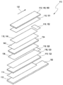
제 1 전극은 적어도 하나의 전극 전도층 및 제 1 전극 전도층과 접촉하는 적어도 하나의 시약 코팅을 포함할 수도 있다. 용어 "전극 전도층" 은 전기적으로 전도성 특성들을 갖는 층을 지칭한다. 용어 "전기 전도성" 은 통상적으로 적어도 100 S/m, 바람직하게는 적어도 103 S/m, 더욱 바람직하게는 적어도 105 S/m 의 S/m 또는 1/Ωm 으로 주어진 전기 전도도를 지칭한다. 제 1 전극 전도층은 금속 층, 바람직하게는 팔라듐, 은 또는 금으로 이루어진 군으로부터 선택된 귀금속 층; 전도성 카본 층, 특히 카본 페이스트 층 중 적어도 하나를 포함할 수도 있다. 그러나, 다른 유형들의 금속들이 추가적으로 또는 대안으로 사용될 수도 있다. 본원에 사용된 바와 같이, 용어 "페이스트" 는 하나 이상의 전도성 성분 및/또는 분말들과 같은 하나 이상의 미립자 성분들, 뿐만 아니라 하나 이상의 유기 바인더 재료들과 같은 하나 이상의 바인더 재료들을 포함하는 비결정 물질을 지칭한다. 부가적으로 또는 대안으로, 제 1 전극 전도층은 전도성 카본 페이스트와 결합된, 스퍼터링된 알루미늄 층과 같은 알루미늄 층을 포함할 수도 있다.The first electrode may comprise at least one electrode conductive layer and at least one reagent coating in contact with the first electrode conductive layer. The term “electrode conductive layer” refers to a layer having electrically conductive properties. The term “electrically conductive” typically refers to an electrical conductivity given as S / m or 1 / mm of at least 10 0 S / m, preferably at least 10 3 S / m, more preferably at least 10 5 S / m. . The first electrode conductive layer comprises a metal layer, preferably a noble metal layer selected from the group consisting of palladium, silver or gold; It may also comprise at least one of a conductive carbon layer, in particular a carbon paste layer. However, other types of metals may additionally or alternatively be used. As used herein, the term “paste” refers to an amorphous material that includes one or more conductive components and / or one or more particulate components such as powders, as well as one or more binder materials such as one or more organic binder materials. do. Additionally or alternatively, the first electrode conductive layer may comprise an aluminum layer, such as a sputtered aluminum layer, combined with a conductive carbon paste.
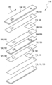
제 1 전극 전도층은 제 1 전극 캐리어 층, 바람직하게는 제 1 전극 캐리어 포일 상에 배치될 수도 있다. 일 실시형태에서, 제 1 전극 캐리어 층은 전도성 카본 페이스트로, 바람직하게는 등질로 코팅될 수도 있다. 대안으로, 위에서 요약된 바와 같이, 제 1 전극 캐리어 층은, 예를 들어 금 또는 팔라듐 상의 금 등으로 코팅될 수도 있다. 테스트 엘리먼트는 연속적인 테이프 제조 프로세스로 생산될 수도 있다. 따라서, 코팅된 층은, 제조 프로세스 중에 릴 상에서 연속적인 테이프의 다중 층 권취가 가능하도록 가능한 한 얇게 코팅될 수도 있다. 제 1 전극은 멀티-층 셋업을 가질 수도 있다. 본원에 사용된 바와 같이, 용어 "전극 캐리어 층" 은 제 1 전극의 추가의 층들 또는 엘리먼트들이 공급될 수도 있는 제 1 전극의 엘리먼트를 지칭한다. 일반적으로, 전극 캐리어 층은 스트립-형과 같은 임의의 형상을 가질 수도 있다. 제 1 전극 캐리어 층은 플라스틱 재료 및/또는 라미네이트 재료 및/또는 종이 재료 및/또는 세라믹 재료와 같은 가요성 기판을 포함할 수도 있다. 전극 캐리어 층은 포일, 특히 폴리머 포일을 포함할 수도 있다. 제 1 전극 전도층은 제 1 전극 캐리어 층의 제 1 길이방향 에지로부터 제 1 전극 캐리어 층의 제 2 길이방향 에지까지 확장될 수도 있다. 제 1 전극 전도층은 제 1 전극 캐리어 층을 완전히 커버할 수도 있다. 따라서, 제 1 전극 전도층의 폭은 제 1 전극 캐리어 층의 폭에 대응하고, 용어 제 1 전극 캐리어 층 및 제 1 전극 전도층의 "폭" 은 연장된 테스트 엘리먼트 방향에 수직한 최대 확장을 지칭한다. 그러나, 이하에서 요약되는 바와 같이, 특히, 테스트 엘리먼트의 핸들이 형성될 수도 있도록 제 1 전극 전도층의 핸들 길이가 제 1 전극 캐리어 층의 길이보다 더 짧을 수도 있도록, 제 1 전극 전도층의 길이가 제 1 전극 캐리어 층의 길이와 상이할 수도 있는 실시형태들이 바람직하다.The first electrode conductive layer may be disposed on the first electrode carrier layer, preferably the first electrode carrier foil. In one embodiment, the first electrode carrier layer may be coated with a conductive carbon paste, preferably homogeneously. Alternatively, as summarized above, the first electrode carrier layer may be coated with, for example, gold or gold on palladium. The test element may be produced in a continuous tape manufacturing process. Thus, the coated layer may be coated as thin as possible to enable multiple layers of continuous tape winding on the reel during the manufacturing process. The first electrode may have a multi-layer setup. As used herein, the term “electrode carrier layer” refers to an element of the first electrode to which additional layers or elements of the first electrode may be supplied. In general, the electrode carrier layer may have any shape such as strip-shaped. The first electrode carrier layer may comprise a flexible substrate, such as a plastic material and / or a laminate material and / or a paper material and / or a ceramic material. The electrode carrier layer may comprise a foil, in particular a polymer foil. The first electrode conductive layer may extend from the first longitudinal edge of the first electrode carrier layer to the second longitudinal edge of the first electrode carrier layer. The first electrode conductive layer may completely cover the first electrode carrier layer. Thus, the width of the first electrode conductive layer corresponds to the width of the first electrode carrier layer, and the term "width" of the first electrode carrier layer and the first electrode conductive layer refers to the maximum expansion perpendicular to the direction of the extended test element. do. However, as summarized below, in particular, the length of the first electrode conductive layer is increased so that the handle length of the first electrode conductive layer may be shorter than the length of the first electrode carrier layer so that the handle of the test element may be formed. Embodiments that may differ from the length of the first electrode carrier layer are preferred.
시약 코팅은 제 1 전극 전도층 위에 코팅된 적어도 하나의 시약 스트라이프를 포함할 수도 있다. 일 실시형태에서, 시약 시트라이프는 제 1 전극 캐리어 층 위에 코팅될 수도 있다. 시약 스트라이프 재료는 분석물과 전기적으로 검출 가능한 전기 화학적 검출 반응을 수행하도록 적어도 하나의 검출기 물질을 포함할 수도 있다. 적어도 하나의 검출기 물질은 글루코스 옥시다제 (GOD) 및/또는 글루코스 탈수소 효소 (GDH) 와 같은 하나 이상의 효소들, 바람직하게는 그 자체로 및/또는 검출기 물질의 다른 성분들과 결합하여, 바람직하게는 검출될 하나 이상의 분석물과 함께 산화 및/또는 환원 반응을 수행하도록 적응되는 하나 이상의 효소들을 포함할 수도 있다. 시약 스트라이프 재료는 하나 이상의 조효소들과 같은 하나 이상의 보조 성분들을 더 포함할 수도 있고/있거나 검출 반응의 하나의 성분으로부터 다른 성분으로 개선된 전하 트랜스퍼를 위해 적응될 수도 있는 하나 이상의 매개체들을 포함할 수도 있다. 시약 스트라이프는 제 1 전극 전도층 위에 균일하게 코팅될 수도 있다. 코팅은 적어도 하나의 코팅 디바이스에서 다이 코팅 프로세스로 수행한 다음에 적어도 하나의 건조기를 통해 건조시킴으로써 건조 프로세스에 의해 수행될 수도 있다.The reagent coating may include at least one reagent stripe coated over the first electrode conductive layer. In one embodiment, the reagent sheet life may be coated over the first electrode carrier layer. The reagent stripe material may include at least one detector material to perform an electrically detectable electrochemical detection reaction with the analyte. The at least one detector material is preferably combined with one or more enzymes, preferably by itself and / or with other components of the detector material, such as glucose oxidase (GOD) and / or glucose dehydrogenase (GDH). It may also comprise one or more enzymes that are adapted to undergo an oxidation and / or reduction reaction with one or more analytes to be detected. The reagent stripe material may further comprise one or more accessory ingredients, such as one or more coenzymes, and / or may include one or more mediators that may be adapted for improved charge transfer from one component to another of the detection reaction. . The reagent stripe may be uniformly coated over the first electrode conductive layer. Coating may be performed by a drying process by performing in a die coating process on at least one coating device and then drying through at least one dryer.
제 2 전극은 적어도 하나의 제 2 전극 전도층을 포함할 수도 있다. 제 2 전극 전도층은 금속 층, 바람직하게는 팔라듐, 은 또는 금으로 이루어진 군으로부터 선택된 금속 층; 전도성 카본 층, 특히 카본 페이스트 층 중 적어도 하나를 포함할 수도 있다. 제 2 전극은 Ag/AgCl, 특히 Ag/AgCl 페이스트를 더 포함할 수도 있다. Ag/AgCl 페이스트는, Ag/AgCl 페이스트로 코팅된 영역이 제 1 전극 전도층의 시약 코팅을 대면할 수 있도록 제 2 전극 전도층 위에 코팅될 수도 있다. 제 2 전극 전도층은 제 2 전극 캐리어 층, 바람직하게는 제 2 전극 캐리어 포일 상에 배치될 수도 있다. 제 2 전극 캐리어 포일은 테스트 엘리먼트의 커버 포일로서 설계될 수도 있다. 일 실시형태에서, 제 2 전극 캐리어 층은 은 층으로 코팅될 수도 있고, 예를 들어 제 2 전극 캐리어 층은 은 층으로 스퍼터링될 수도 있다. 제 2 전극 전도층은 제 2 전극 캐리어 층의 제 1 길이방향 에지로부터 제 2 전극 캐리어 층의 제 2 길이방향 에지까지 확장될 수도 있다. 제 2 전극 전도층은 제 2 전극 캐리어 층을 완전히 커버할 수도 있다. 따라서, 제 2 전극 전도층의 폭은 제 2 전극 캐리어 층의 폭에 대응하고, 용어 제 2 전극 캐리어 층 및 제 2 전극 전도층의 "폭" 은 연장된 테스트 엘리먼트 방향에 수직한 최대 확장을 지칭한다.The second electrode may comprise at least one second electrode conductive layer. The second electrode conductive layer comprises a metal layer, preferably a metal layer selected from the group consisting of palladium, silver or gold; It may also comprise at least one of a conductive carbon layer, in particular a carbon paste layer. The second electrode may further comprise Ag / AgCl, in particular Ag / AgCl paste. The Ag / AgCl paste may be coated over the second electrode conductive layer such that a region coated with Ag / AgCl paste can face the reagent coating of the first electrode conductive layer. The second electrode conductive layer may be disposed on the second electrode carrier layer, preferably the second electrode carrier foil. The second electrode carrier foil may be designed as a cover foil of the test element. In one embodiment, the second electrode carrier layer may be coated with a silver layer, for example the second electrode carrier layer may be sputtered with a silver layer. The second electrode conductive layer may extend from the first longitudinal edge of the second electrode carrier layer to the second longitudinal edge of the second electrode carrier layer. The second electrode conductive layer may completely cover the second electrode carrier layer. Thus, the width of the second electrode conductive layer corresponds to the width of the second electrode carrier layer, and the term “width” of the second electrode carrier layer and the second electrode conductive layer refers to the maximum expansion perpendicular to the direction of the extended test element. do.
테스트 엘리먼트는 체액의 샘플을 수용할 수 있는 적어도 하나의 캐필러리를 포함한다. 본원에 사용된 바와 같이, 용어 "캐필러리" 는 캐필러리 힘들에 의해 체액의 샘플을 이송하고/하거나 체액의 샘플을 수용하도록 적응되는 엘리먼트를 지칭한다. 캐필러리 엘리먼트는 체액의 샘플을 수용하도록 구성된 적어도 하나의 체적, 예를 들어 직사각형 단면 및/또는 둥근 단면 및/또는 다각형 단면과 같은 임의의 단면을 갖는 하나 이상의 캐필러리 캡들 및/또는 하나 이상의 캐필러리 슬롯들 및/또는 하나 이상의 캐필러리 튜브들을 포함할 수도 있다.The test element includes at least one capillary capable of receiving a sample of bodily fluid. As used herein, the term “capillary” refers to an element that is adapted to transport a sample of bodily fluid and / or to receive a sample of bodily fluid by capillary forces. The capillary element has one or more capillary caps and / or one or more having at least one volume configured to receive a sample of bodily fluid, for example a rectangular cross section and / or a round cross section and / or a polygonal cross section. Capillary slots and / or one or more capillary tubes may be included.
제 1 전극 및 제 2 전극은 캐필러리의 대향 사이드들 상에 배열된다. 제 1 전극 및 제 2 전극은, 제 1 전극의 표면이 제 2 전극의 표면을 대면하도록 대향하는 전극들로서 배열된다. 제 1 전극 및 제 2 전극은, 캐필러리 충진 동안 제 1 전극 및 제 2 전극이 동시에 그리고 동일한 속도로 습윤되도록 배열된다. 캐필러리의 충진된 체적의 증분 (dV) 당 제 1 전극의 습윤된 표면적의 증분 (dA1) 은 제 2 전극의 습윤된 표면적 증분 (dA2) 과 항상 동일할 수도 있다. 결과적으로, 본원에 사용된 바와 같이, 용어 "동일한 속도로 습윤" 은, 이 문맥에서, 일반적으로 dA1/dV = dA2/dV, 즉 습윤된 표면적 및 충진된 체적의 비율들이 적어도 평형 상태에 도달하기 위해 필요한 시간 후에 양자 모두의 전극에 대해 동일하다는 사실을 지칭한다. 그러나, 습윤의 시간 종속성은 반드시 동일하지는 않다, 즉, 방정식 dA1/dt = dA2/dt 은 모든 시간들에 대해 참일 수도 있지만, 또한 모든 시점에 대해 참이 아닐 수도 있다. 제 1 전극 및 제 2 전극은 평행하게, 특히 적어도 캐필러리의 길이에 의해 정의된 방향에서 서로 평행한 표면들로서 정렬될 수도 있다. 또한, 요약된 바와 같이, 제 1 및 제 2 전극은 동일한 치수를 가질 수도 있고, 비-구조화된 형상을 가질 수도 있다. 제 1 전극은 캐필러리의 전 길이 (full length) 를 넘어 확장할 수도 있다. 제 2 전극은 캐필러리의 전 길이를 넘어 확장할 수도 있다. 본원에 사용된 바와 같이, 용어 "캐필러리의 길이" 는 테스트 엘리먼트 내에서 일 차원으로 캐필러리의 최대 확장을 지칭한다. 일 실시형태에서, 캐필러리는, 이 경우에서 캐필러리의 길이가 연장된 테스트 엘리먼트 방향에 수직한 캐필러리의 최대 확장을 지칭하도록 연장된 테스트 엘리먼트 방향에 수직하게 확장될 수도 있다. 대안의 실시형태에서, 캐필러리는, 이 경우에서 캐필러리의 길이가 연장된 테스트 엘리먼트 방향을 따른 캐필러리의 최대 확장을 지칭하도록 연장된 테스트 엘리먼트 방향을 따라 확장될 수도 있다.The first electrode and the second electrode are arranged on opposite sides of the capillary. The first electrode and the second electrode are arranged as opposing electrodes such that the surface of the first electrode faces the surface of the second electrode. The first and second electrodes are arranged such that during capillary filling the first and second electrodes wet simultaneously and at the same rate. The increment (dA1) of the wetted surface area of the first electrode per increment (dV) of the filled volume of the capillary may always be the same as the wetted surface area increment (dA2) of the second electrode. As a result, as used herein, the term "wetting at the same rate" means, in this context, that in general, dA1 / dV = dA2 / dV, i.e., the ratios of wet surface area and filled volume at least reach equilibrium. It refers to the fact that both are the same for both electrodes after the time required for the purpose. However, the time dependence of wetting is not necessarily the same, ie the equation dA1 / dt = dA2 / dt may be true for all times but also not true for every time point. The first electrode and the second electrode may be arranged in parallel, in particular as surfaces parallel to each other in at least the direction defined by the length of the capillary. In addition, as summarized, the first and second electrodes may have the same dimensions or may have a non-structured shape. The first electrode may extend beyond the full length of the capillary. The second electrode may extend beyond the full length of the capillary. As used herein, the term “length of capillary” refers to the maximum expansion of the capillary in one dimension within the test element. In one embodiment, the capillary may in this case extend perpendicular to the extended test element direction to refer to the maximum extension of the capillary, in which case the length of the capillary is perpendicular to the extended test element direction. In alternative embodiments, the capillary may in this case extend along the extended test element direction to refer to the maximum extension of the capillary along the extended test element direction.
제 1 전극 및 제 2 전극은, 캐필러리 충진 동안 제 1 전극 및 제 2 전극이 동시에 습윤되도록 배열된다. 캐필러리의 충진된 부피의 증분 (dV) 당 제 1 전극의 습윤된 표면적의 증분 (dA1) 은 제 2 전극의 습윤된 표면적의 증분 (dA2) 과 항상 동일할 수도 있다. 본원에 사용된 바와 같이, 용어 "캐필러리 충진" 은 체액의 샘플을 수용하는 프로세스를 지칭한다.The first electrode and the second electrode are arranged such that the first electrode and the second electrode wet simultaneously during capillary filling. The increment (dA1) of the wetted surface area of the first electrode per increment (dV) of the filled volume of the capillary may always be equal to the increment (dA2) of the wetted surface area of the second electrode. As used herein, the term “capillary filling” refers to the process of receiving a sample of bodily fluid.
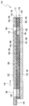
제 1 전극과 제 2 전극 및 제 1 전극과 제 2 전극 사이의 캐필러리는 전기화학 셀을 형성하며, 테스트 엘리먼트는 전기화학 셀의 충진 레벨과 독립적으로 적어도 하나의 분석물을 검출하도록 구성된다. 전기화학 셀은 캐필러리의 전 길이를 넘어 확장할 수도 있다. 따라서, 제 1 전극 및 제 2 전극은 캐필러리의 전 길이를 넘어 확장할 수도 있다.The capillary between the first and second electrodes and the first and second electrodes forms an electrochemical cell, and the test element is configured to detect at least one analyte independent of the filling level of the electrochemical cell. . The electrochemical cell may extend beyond the full length of the capillary. Thus, the first electrode and the second electrode may extend beyond the full length of the capillary.
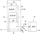
체액의 샘플은 사이드 도즈 포지션, 상부 도즈 포지션, 프론트 도즈 포지션 중 하나 이상에 공급 가능할 수도 있다. 본원에 사용된 바와 같이, 용어 "사이드 도즈 포지션" 은 체액의 샘플이 공급 가능한 테스트 엘리먼트의 연장된 에지 상의 포지션을 지칭한다, 예를 들어 테스트 엘리먼트는 테스트 엘리먼트의 에지들에 적어도 2 개의 대향하는 개구들을 포함할 수도 있다. 사이드 도즈 포지션은 손가락 스틱으로부터 캐필러리 혈액에 대한 이상적인 공급 포지션일 수도 있다. 본원에 사용된 바와 같이, 용어 "상부 도즈 포지션" 은 체액의 샘플이 테스트 엘리먼트의 층-셋업을 통해 위로부터 캐필러리 내로 공급될 수도 있는 포지션을 나타낸다. 테스트 엘리먼트는 상부 도즈 포지션 및 커버 포일을 통해 캐필러리 안으로 연장되는 추가의 스루 홀을 포함할 수도 있다. 본원에 사용된 바와 같이, 용어 "커버 포일" 은 테스트 엘리먼트의 층 셋업을 정의하는 테스트 엘리먼트의 엘리먼트, 예를 들어 상부 포일을 지칭한다. 커버 포일은 제 1 전극 캐리어 층 또는 제 2 전극 캐리어 층으로서 구성될 수도 있다. 스루 홀은, 이 스루 홀이 적어도 하나의 캐필러리 벽의 하나의 에지에서 캐필러리를 터치할 수 있도록 포지셔닝될 수도 있다. 상부 도즈 포지션은 트랜스퍼 디바이스, 예를 들어 피펫으로 샘플을 투여하기 위한 이상적인 공급 포지션일 수도 있다. 또한, 테스트 엘리먼트가 적어도 하나의 상부 도즈 포지션을 포함하는 경우, 캐필러리 공간의 적합한 배기가, 예를 들어 벤팅 엘리먼트, 예를 들어 작은 벤트 홀 개구 또는 벤팅 막을 통해 가능하면 모든 사이드들 상에서 캐필러리를 폐쇄하는 것이 가능할 수도 있다. 본원에 사용된 바와 같이, 용어 "프론트 도즈 포지션" 은 테스트 엘리먼트의 프론트 페이스에서의 포지션을 지칭하고, 용어 "프론트 페이스" 는 테스트 엘리먼트의 폭의 전면 영역을 지칭한다. 예를 들어, 프론트 도즈 포지션은 프론트 페이스에서 개방 사이드일 수도 있다. 사이드 도즈 포지션, 상부 도즈 포지션 및 프론트 도즈 포지션은, 추가의 측정 디바이스 안으로 트랜스퍼되는 샘플이 없도록, 추가의 측정 디바이스, 예를 들어 미터 안으로 삽입된 테스트 엘리먼트의 영역까지의 거리에 포지셔닝될 수도 있다. 이것은, 위생 측면들 및 세척 및 소독 요건들 하에서 유리하다.The sample of bodily fluid may be supplyable to one or more of a side dose position, an upper dose position, and a front dose position. As used herein, the term “side dose position” refers to a position on an extended edge of a test element capable of supplying a sample of bodily fluid, eg, the test element has at least two opposite openings at the edges of the test element. It may also include. The side dose position may be an ideal supply position for capillary blood from the finger stick. As used herein, the term “top dose position” refers to a position where a sample of bodily fluid may be supplied into the capillary from above through a layer-setup of a test element. The test element may include additional through holes extending into the capillary through the upper dose position and cover foil. As used herein, the term “cover foil” refers to an element of a test element, eg, an upper foil, that defines a layer setup of the test element. The cover foil may be configured as a first electrode carrier layer or a second electrode carrier layer. The through hole may be positioned such that the through hole can touch the capillary at one edge of the at least one capillary wall. The upper dose position may be an ideal feed position for administering the sample with a transfer device, eg a pipette. In addition, where the test element comprises at least one upper dose position, suitable exhaust of the capillary space is possible on all sides, if possible, for example through a venting element, for example a small vent hole opening or venting membrane. It may be possible to close the lid. As used herein, the term “front dose position” refers to the position at the front face of the test element, and the term “front face” refers to the front region of the width of the test element. For example, the front dose position may be the open side at the front face. The side dose position, the top dose position and the front dose position may be positioned at a distance to an area of the test element inserted into the further measurement device, eg a meter, such that no sample is transferred into the further measurement device. This is advantageous under hygienic aspects and cleaning and disinfection requirements.
테스트 엘리먼트는 길이방향 축을 따라 확장한 장방형 (elongated) 형상을 가질 수도 있고, 캐필러리는 테스트 엘리먼트의 길이방향 축을 따라 적어도 부분적으로 확장한다. 용어 "길이방향 축을 따라 적어도 부분적으로 확장하는" 은 캐필러리가 길이방향 축을 따라 완전히 확장할 수도 있는 실시형태 및/또는 캐필러리의 부분들이 길이방향 축을 따라 확장하지 않을 수도 있는 실시형태를 지칭한다. 특히,이 실시형태는 캐필러리 내의 샘플이 건조되지 않을 것이기 때문에 1 분 보다 상당히 긴 테스팅 시간들, 예를 들어 5 분 보다 긴 테스팅 시간들이 요구되는 경우 사용될 수도 있다. 또한, 이 실시형태는, 샘플이 추가의 디바이스로, 예를 들어 가열 디바이스, 바람직하게는 미터 내의 온도 제어된 가열 디바이스로 이송되어야 하는 경우에, 테스트 파라미터들이 주변 온도 위의 온도까지 가열될 필요가 있을 수도 있는 경우에 사용될 수도 있다. 테스트 엘리먼트는 추가의 디바이스 안으로 삽입 가능한 영역을 포함할 수도 있다. 캐필러리는, 삽입 가능한 영역의 방향으로 캐필러리의 단부에 벤트 홀 개구와 같은 벤트 홀 개구를 포함할 수도 있다. 이 실시형태에서, 제 1 전극은 소수성 표면을 생성할 수도 있는 삽입 가능한 영역의 방향에서 제 2 시약 코팅을 포함할 수도 있다. 소수성 표면은 체액의 샘플을 벤트 홀까지 통과시켜, 다른 디바이스를 오염시키는 것을 방해할 수도 있다. 신뢰성 있고 빠른 샘플 이송을 보장하기 위해, 일반적으로 캐필러리 벽들은 친수성일 수도 있다. 따라서, 캐필러리 벽의 표면들, 특히 캐필러리의 대향 사이드들 상에 배열되는 제 1 전극 및 제 2 전극의 표면들은 적어도 하나의 세제 및/또는 적어도 하나의 계면 활성제로 처리될 수도 있다.The test element may have an elongated shape extending along the longitudinal axis and the capillary at least partially extends along the longitudinal axis of the test element. The term “expanding at least partially along the longitudinal axis” refers to an embodiment in which the capillary may fully extend along the longitudinal axis and / or an embodiment in which portions of the capillary may not extend along the longitudinal axis. In particular, this embodiment may be used when testing times longer than one minute, for example testing times longer than five minutes, are required because the sample in the capillary will not be dried. In addition, this embodiment requires that the test parameters need to be heated to a temperature above the ambient temperature if the sample is to be transferred to an additional device, for example to a heating device, preferably a temperature controlled heating device in the meter. It may be used where there may be. The test element may include an insertable area into the additional device. The capillary may include a vent hole opening, such as a vent hole opening, at the end of the capillary in the direction of the insertable region. In this embodiment, the first electrode may comprise a second reagent coating in the direction of the insertable region that may produce a hydrophobic surface. The hydrophobic surface may pass a sample of bodily fluid to the vent hole, preventing it from contaminating other devices. In order to ensure reliable and fast sample transfer, capillary walls may generally be hydrophilic. Thus, the surfaces of the capillary wall, in particular the surfaces of the first and second electrodes arranged on opposite sides of the capillary, may be treated with at least one detergent and / or at least one surfactant.
테스트 엘리먼트는 길이방향 축을 따라 확장되는 장방형 형상을 가질 수도 있고, 캐필러리는 길이방향 축에 수직하게 적어도 부분적으로 확장한다. 용어 "길이방향 축에 수직하게 적어도 부분적으로 확장하는" 은 캐필러리가 길이방향 축에 수직하게 확장할 수도 있는 실시형태 및/또는 캐필러리의 부분들이 길이방향 축에 수직하게 확장하지 않을 수도 있는 실시형태를 지칭한다. 캐필러리는 테스트 엘리먼트의 제 1 길이방향 에지에서의 제 1 개구로부터 테스트 엘리먼트의 제 2 길이방향 에지에서의 제 2 개구까지 확장할 수도 있다. 캐필러리는 테스트 엘리먼트의 프론트 페이스에 오픈 사이드를 가질 수도 있다. 테스트 엘리먼트는 테스트 엘리먼트의 프론트 페이스에 위치된 프론트 도즈 포지션을 가질 수도 있다. 캐필러리는 벤트 홀을 포함할 수도 있다.The test element may have a rectangular shape that extends along the longitudinal axis and the capillary extends at least partially perpendicular to the longitudinal axis. The term “at least partially extending perpendicular to the longitudinal axis” refers to embodiments in which the capillary may extend perpendicular to the longitudinal axis and / or practice that portions of the capillary may not extend perpendicular to the longitudinal axis. Refers to form. The capillary may extend from the first opening at the first longitudinal edge of the test element to the second opening at the second longitudinal edge of the test element. The capillary may have an open side at the front face of the test element. The test element may have a front dose position located at the front face of the test element. The capillary may include a vent hole.
테스트 엘리먼트는 제 1 개구 또는 제 2 개구 중 하나 또는 양자 모두 상에 위치된 사이드 도즈 포지션을 포함할 수도 있다. 일 실시형태에서, 캐필러리는 3 개의 사이드들에서 개방될 수도 있다. 캐필러리는 체액의 샘플을 수용하기 위한 3 개의 개구들을 포함할 수 있고, 예를 들어 캐필러리는 테스트 엘리먼트의 대향 에지들 상의 캐필러리의 대향하는 개구들과 같은 적어도 2 개의 사이드 도즈 포지션들 및 상부 개구 또는 전면 개구와 같은 제 3 도즈 포지션으로부터 샘플을 수용할 수 있다. 테스트 엘리먼트가 사이드 도즈 포지션 및 이에 따른 제 1 개구 및 제 2 개구를 포함하면, 이들 개구들 중 하나는 샘플 투여에 사용될 수도 있고 다른 개구는 벤트 홀 개구의 기능을 갖는다. 이 실시형태에서, 별개의 벤트 홀 개구는 필요하지 않다. 캐필러리 외측이지만 체액의 샘플을 수용하기 위한 개구 바로 옆에 위치된 테스트 엘리먼트의 적어도 하나의 벽은 적어도 하나의 소수성 코팅에 의해 적어도 부분적으로 코팅될 수도 있다. 소수성 코팅은 체액의 샘플의 캐필러리 외부로의 확산을 회피할 수도 있고, 따라서 캐필러리의 충진을 지원할 수도 있다. 예를 들어, 소수성 코팅이 제 2 전극 캐리어 층 상부에, 예를 들어 상부 도즈 포지션에, 및/또는 제 1 전극 캐리어 층의 전방에 공급될 수도 있다.The test element may include a side dose position located on one or both of the first opening or the second opening. In one embodiment, the capillary may be open on three sides. The capillary may comprise three openings for receiving a sample of body fluid, for example the capillary has at least two side dose positions, such as opposing openings of the capillary on opposite edges of the test element. And a sample from a third dose position, such as a top opening or front opening. If the test element comprises a side dose position and thus a first opening and a second opening, one of these openings may be used for sample administration and the other opening has the function of a vent hole opening. In this embodiment, no separate vent hole opening is needed. At least one wall of the test element outside the capillary but located next to the opening for receiving a sample of body fluid may be at least partially coated by at least one hydrophobic coating. The hydrophobic coating may avoid diffusion of the sample of bodily fluid out of the capillary and thus may support filling of the capillary. For example, a hydrophobic coating may be supplied over the second electrode carrier layer, for example in an upper dose position, and / or in front of the first electrode carrier layer.
테스트 엘리먼트는 스트립 핸들을 포함할 수도 있다. 본원에 사용된 바와 같이, 용어 "스트립 핸들" 은 테스트 엘리먼트를 취급할 때, 예를 들어 테스트 엘리먼트를 저장 바이알에서 꺼낼 때 테스트 엘리먼트를 추가의 디바이스 안으로 삽입하거나 테스트 엘리먼트를 추가의 디바이스로부터 잡아당길 때와 같이 체액의 샘플과 접촉하는 것을 피하도록 구성된 테스트 엘리먼트의 엘리먼트를 지칭한다. 테스트 엘리먼트는 적어도 하나의 캐리어 엘리먼트의 상부에 배치된 층 셋업을 포함할 수도 있고, 테스트 엘리먼트의 길이방향 방향으로 캐리어 엘리먼트는 층 셋업으로부터 돌출하여, 이에 의해 스트립 핸들을 형성한다.The test element may include a strip handle. As used herein, the term “strip handle” refers to when handling a test element, for example when inserting a test element into an additional device or pulling a test element out of an additional device when removing the test element from a storage vial. Refers to an element of a test element configured to avoid contact with a sample of bodily fluid. The test element may comprise a layer setup disposed on top of the at least one carrier element, in the longitudinal direction of the test element the carrier element protrudes from the layer setup, thereby forming a strip handle.
테스트 엘리먼트는 적어도 하나의 캐리어 엘리먼트를 포함할 수도 있다. 본원에 사용된 바와 같이, 용어 "캐리어 엘리먼트" 는 하나 이상의 컴포넌트들을 포함하는 임의의 엘리먼트를 지칭한다. 캐리어 엘리먼트는 적어도 하나의 테스트 필드와 같은 테스트 엘리먼트의 다른 컴포넌트들을 운반하도록 적응될 수도 있다. 따라서, 캐리어 엘리먼트는 라미네이트 셋업과 같은 다중층 셋업의 단일-층 셋업을 포함할 수도 있다. 캐리어 엘리먼트는 플라스틱 재료들 및/또는 종이 재료들 및/또는 판지 재료들 및/또는 세라믹 재료들과 같은 하나 이상의 재료들을 포함할 수도 있다. 가장 바람직하게는, 캐리어 엘리먼트는 가요성 기판, 예를 들어 폴리 카보네이트, 폴리에틸렌, 폴리에틸렌 테레프탈레이트, 아크릴로니트릴-부타디엔-스티렌으로 이루어진 군으로부터 선택된 하나 이상의 플라스틱 재료들을 포함할 수도 있다. 그러나, 추가하여 또는 대안으로, 다른 플라스틱 재료들이 공급 가능하다. 부가적으로 또는 대안으로, 캐리어 엘리먼트는 알루미늄과 같은 하나 이상의 금속 재료들을 포함할 수도 있다. 또한, 라미네이트 재료들과 같은 재료들의 조합이 가능하며, 이 조합들은 층 셋업에서와 같이 플라스틱 재료들 및 금속 재료들의 조합과 같은 2 이상의 상이한 유형들의 재료들을 포함할 수도 있다. 일반적으로, 캐리어 엘리먼트는 스트립-형과 같은 임의의 형상을 가질 수도 있다. 적어도 하나의 캐리어 포일은 폴리머 포일일 수도 있다. 적어도 하나의 캐리어 포일은 테스트 엘리먼트의 안정성을 제공하도록 구성될 수도 있다.The test element may include at least one carrier element. As used herein, the term “carrier element” refers to any element that includes one or more components. The carrier element may be adapted to carry other components of the test element, such as at least one test field. Thus, the carrier element may comprise a single-layer setup of a multilayer setup, such as a laminate setup. The carrier element may comprise one or more materials such as plastic materials and / or paper materials and / or cardboard materials and / or ceramic materials. Most preferably, the carrier element may comprise one or more plastic materials selected from the group consisting of flexible substrates such as polycarbonate, polyethylene, polyethylene terephthalate, acrylonitrile-butadiene-styrene. However, in addition or alternatively, other plastic materials may be supplied. Additionally or alternatively, the carrier element may comprise one or more metallic materials such as aluminum. Combinations of materials, such as laminate materials, are also possible, and the combinations may include two or more different types of materials, such as a combination of plastic materials and metal materials, such as in a layer setup. In general, the carrier element may have any shape such as strip-shaped. At least one carrier foil may be a polymer foil. At least one carrier foil may be configured to provide stability of the test element.
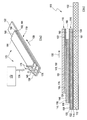
테스트 엘리먼트는 제 1 전극 및 제 2 전극을 추가의 디바이스와, 특히 미터와 접촉시키도록 구성된 제 1 전극 접촉존 및 제 2 전극 접촉존을 포함할 수도 있다. 일 실시형태에서, 제 1 전극 접촉존 및 제 2 전극 접촉존은 테스트 엘리먼트의 동일한 사이드로부터 전기적으로 접촉되도록 구성될 수도 있다. 제 1 전극 접촉존 및 제 2 전극 접촉존은 테스트 엘리먼트의 층 셋업의 상이한 층들에 배열될 수도 있고, 여기서 제 1 전극 접촉존 및 제 2 전극 접촉존 중 하나는 제 1 전극 접촉존 및 제 2 전극 접촉존 중 다른 하나 위로 돌출할 수도 있다. 제 1 전극 접촉존 및 제 2 전극 접촉존은 층 셋업의 계단 구성의 상이한 스텝들을 형성할 수도 있다. 예를 들어, 제 1 전극 접촉존 및 제 2 전극 접촉존은 테스트 엘리먼트의 일 단부에서의 2 개의 직사각형 존들일 수도 있다. 제 1 및 제 2 전극 접촉존들은 각각 추가의 디바이스의 적어도 하나의 커넥터, 예를 들어 미터 커넥터 핀들에 의해 타격될 수도 있다. 추가의 디바이스는 2 개의 커넥터 쌍들을 가질 수도 있고, 하나의 쌍은 제 1 및 제 2 전극 각각에 대한 것이다. 각각의 커넥터 쌍의 하나의 커넥터는 테스트 엘리먼트를 통한 전류 흐름을 지원하도록 구성될 수도 있다. 다른 커넥터는 전압을 검출하는데 사용될 수도 있다. 4-와이어-기법으로도 지칭된 이러한 구성은 추가의 디바이스의 전자 제어기가, 제 1 전극 접촉존 및 제 2 전극 접촉존들 및 커넥터들의 접속 스폿들에서 기생 전달 저항들에 의해 유도된 전압 강하를 보상하는 것을 허용할 수도 있다. 그러나, 이하에서 상세히 요약되는 바와 같이, 제 1 전극 및 제 2 전극이 테스트 엘리먼트의 동일한 사이드로부터의 전기적 접촉을 허용하도록 대향하는 전극들로서 구성될 수도 있기 때문에, 제 1 전극 또는 제 2 전극은 적어도 하나의 전기적으로 전도성 회전 엘리먼트에 의해 전기적으로 접촉될 수도 있다.The test element may comprise a first electrode contact zone and a second electrode contact zone configured to contact the first electrode and the second electrode with an additional device, in particular with the meter. In one embodiment, the first electrode contact zone and the second electrode contact zone may be configured to be in electrical contact from the same side of the test element. The first electrode contact zone and the second electrode contact zone may be arranged in different layers of the layer setup of the test element, wherein one of the first electrode contact zone and the second electrode contact zone is a first electrode contact zone and a second electrode. It may protrude over the other of the contact zones. The first electrode contact zone and the second electrode contact zone may form different steps of the step configuration of the layer setup. For example, the first electrode contact zone and the second electrode contact zone may be two rectangular zones at one end of the test element. The first and second electrode contact zones may each be hit by at least one connector, eg, meter connector pins, of the additional device. The further device may have two connector pairs, one pair for each of the first and second electrodes. One connector of each connector pair may be configured to support current flow through the test element. Other connectors may be used to detect the voltage. This configuration, also referred to as a four-wire technique, allows the electronic controller of the additional device to overcome the voltage drop induced by parasitic transfer resistances in the connection spots of the first electrode contact zone and the second electrode contact zones and connectors. You may allow to compensate. However, as summarized in detail below, the first electrode or the second electrode is at least one because the first electrode and the second electrode may be configured as opposing electrodes to allow electrical contact from the same side of the test element. It may be in electrical contact by means of an electrically conductive rotating element.
일 실시형태에서, 제 1 전극 접촉존 및 제 2 전극 접촉존은 테스트 엘리먼트의 대향 사이드들로부터 전기적으로 접촉되도록 구성될 수도 있다. 제 1 전극은 테스트 엘리먼트 층 셋업에서 돌출한 제 1 전극 접촉존을 통해 접촉될 수도 있다. 커버 포일 및 스페이서 포일을 통과한 펀칭된 홀은 제 2 전극 접촉존, 특히 접촉 홀로서 구성될 수도 있다. 따라서, 위에서 요약된 바와 동일한 사이드 접촉에 대해 추가적인 전기적으로 전도성 회전 엘리먼트가 요구되지 않을 수도 있다. 제 1 및 제 2 전극 접촉존들은 추가의 디바이스의 적어도 하나의 커넥터, 예를 들어 미터 커넥터 핀들에 의해 타격될 수도 있다. 바람직하게, 추가의 디바이스는 2 개의 커넥터 쌍들을 가질 수도 있고, 하나의 쌍은 제 1 전극 및 제 2 전극 각각에 대한 것이다. 한 쌍의 커넥터들은 테스트 엘리먼트의 일 사이드로부터 제 1 또는 제 2 전극들 중 하나와 접촉할 수도 있는 반면에, 다른 쌍은 테스트 엘리먼트의 대향 사이드로부터 제 1 또는 제 2 전극들 중 다른 하나와 접촉할 수도 있다.In one embodiment, the first electrode contact zone and the second electrode contact zone may be configured to be in electrical contact from opposite sides of the test element. The first electrode may be contacted through a first electrode contact zone protruding in the test element layer setup. The punched holes through the cover foil and the spacer foil may be configured as second electrode contact zones, in particular contact holes. Thus, no additional electrically conductive rotating element may be required for the same side contact as summarized above. The first and second electrode contact zones may be hit by at least one connector of the additional device, for example meter connector pins. Preferably, the additional device may have two connector pairs, one pair for each of the first electrode and the second electrode. The pair of connectors may contact one of the first or second electrodes from one side of the test element, while the other pair may contact the other of the first or second electrodes from the opposite side of the test element. It may be.
제 1 전극 또는 제 2 전극 중 하나 또는 양자 모두는 적어도 하나의 전기적으로 전도성 회전 엘리먼트에 의해 전기적으로 접촉될 수도 있고, 제 1 또는 제 2 전극은 각각 제 1 방향을 향하도록 배향될 수도 있고, 전기적으로 전도성 회전 엘리먼트는 제 1 방향과 반대 방향인 제 2 방향으로부터 접촉 가능할 수도 있다. 전기적으로 전도성 회전 엘리먼트는 제 1 섹션 및 제 2 섹션을 갖는 전기적 전도성 포일 또는 전기적 전도성 층 중 적어도 하나를 포함할 수도 있고, 제 1 섹션은 제 1 전극 또는 제 2 전극을 각각 전기적으로 접촉하고, 제 2 섹션은 전기적으로 접촉 가능하다. 예를 들어, 전기적으로 전도성 회전 엘리먼트는 전도성 접착제 층으로서 구성될 수도 있다. 전기적으로 전도성 회전 엘리먼트는 제 1 전극 또는 제 2 전극을 각각 포함하는 적어도 하나의 층에 의해 부분적으로 커버될 수도 있고, 제 2 섹션은 커버되지 않은 영역에 위치될 수도 있다. 본원에 사용된 바와 같이, 용어 "부분적으로 커버된" 은, 전기적으로 전도성 회전 엘리먼트의 부분들이 제 1 또는 제 2 전극을 포함하는 적어도 하나의 층에 의해 커버될 수도 있고 전기적으로 전도성 회전 엘리먼트의 부분들이 커버되지 않을 수도 있다는 것을 지칭한다. 전기적으로 전도성 회전 엘리먼트는 제 1 전극 또는 제 2 전극에 각각 라미네이트될 수도 있다.One or both of the first electrode or the second electrode may be electrically contacted by at least one electrically conductive rotating element, and the first or second electrode may be oriented to face the first direction, respectively, The conductive rotating element may thus be contactable from a second direction opposite the first direction. The electrically conductive rotating element may comprise at least one of an electrically conductive foil or an electrically conductive layer having a first section and a second section, wherein the first section is in electrical contact with the first electrode or the second electrode, respectively, The two sections are electrically contactable. For example, the electrically conductive rotating element may be configured as a conductive adhesive layer. The electrically conductive rotating element may be partially covered by at least one layer each comprising a first electrode or a second electrode, and the second section may be located in an uncovered area. As used herein, the term “partially covered” means that portions of the electrically conductive rotating element may be covered by at least one layer comprising a first or second electrode and that part of the electrically conductive rotating element. They may not be covered. The electrically conductive rotating element may be laminated to the first electrode or the second electrode, respectively.
테스트 엘리먼트는 층 셋업을 포함할 수 있고, 제 1 전극은 적어도 하나의 제 1 전극 캐리어 층 상에 배치된 적어도 하나의 제 1 전극 전도층을 포함할 수 있으며, 제 2 전극은 적어도 하나의 제 2 전극 캐리어 층 상에 배치된 적어도 하나의 제 2 전극 전도층을 포함할 수도 있다. 층 셋업은, 제 1 전극 전도층이 캐필러리를 사이에 두고 제 2 전극 전도층을 향하도록 배열될 수도 있다. 적어도 하나의 스페이서 층은 제 1 전극 전도층과 제 2 전극 전도층 사이에 배치될 수도 있다. 추가로, 층 셋업은 적어도 하나의 접착제 층을 포함할 수도 있다. 전기화학 셀의 높이는 제 1 전극과 제 2 전극 사이의 접착제 층들 및 스페이서 층의 두께에 의해 정의될 수도 있다. 적어도 하나의 접착제 층은 캐리어 엘리먼트와 제 1 전극 캐리어 층 사이 및/또는 시약 코팅과 스페이서 층 사이에 배열될 수도 있는 실시형태들이 실현 가능하다. 예를 들어, 적어도 하나의 접착제 층이 캐리어 엘리먼트와 제 1 전극 캐리어 층 사이에 배열될 수도 있는 경우, 적어도 하나의 접착제 층은, 전기화학 셀의 포지션에 의해 한정된 영역이 캐리어 엘리먼트와 제 1 전극 사이에 갭이 형성될 수 있도록 접착제 층에 의해 커버되지 않도록 포지셔닝될 수도 있다. 따라서, 사용자가 테스트 엘리먼트를 고의로 구부리지 않을 수도 있는 경우에, 제 1 전극면과 제 2 전극면 사이의 거리는 영향을 받지 않을 수도 있다. 또한, 적어도 하나의 접착제 층은 전도성 접착제 층, 예를 들어 커버 포일과 제 2 전극 전도층 및/또는 제 2 전극 전도층과 스페이서 층 사이에 배열될 수도 있는, 은-계 접착제일 수도 있다. 그러나, 접착제 층들의 다른 배열들이 실현 가능할 수도 있다.The test element may comprise a layer setup, the first electrode may comprise at least one first electrode conductive layer disposed on the at least one first electrode carrier layer, and the second electrode may be at least one second It may also comprise at least one second electrode conductive layer disposed on the electrode carrier layer. The layer setup may be arranged such that the first electrode conductive layer faces the second electrode conductive layer with the capillary interposed therebetween. At least one spacer layer may be disposed between the first electrode conductive layer and the second electrode conductive layer. In addition, the layer setup may include at least one adhesive layer. The height of the electrochemical cell may be defined by the thickness of the spacer layer and the adhesive layers between the first electrode and the second electrode. Embodiments may be realized in which at least one adhesive layer may be arranged between the carrier element and the first electrode carrier layer and / or between the reagent coating and the spacer layer. For example, where at least one adhesive layer may be arranged between the carrier element and the first electrode carrier layer, the at least one adhesive layer has a region defined by the position of the electrochemical cell between the carrier element and the first electrode. It may be positioned so that it is not covered by the adhesive layer so that a gap can be formed. Thus, if the user may not intentionally bend the test element, the distance between the first electrode surface and the second electrode surface may not be affected. In addition, the at least one adhesive layer may be a conductive adhesive layer, for example a silver-based adhesive, which may be arranged between the cover foil and the second electrode conductive layer and / or the second electrode conductive layer and the spacer layer. However, other arrangements of adhesive layers may be feasible.
테스트 엘리먼트는 층 셋업을 포함할 수도 있다. 작업 전극은 적어도 하나의 제 1 전극 전도층을 포함할 수도 있다. 제 1 전극 전도층은 카본 잉크 코팅을 포함할 수도 있다. 제 1 전극 전도층은 적어도 하나의 제 1 전극 캐리어 층 상에 배치될 수도 있다. 제 1 전극 캐리어 층은 포일, 예를 들어 상부 포일일 수도 있다. 작업 전극은 제 1 전극 전도층과 접촉하는, 적어도 하나의 시약 코팅, 예를 들어 검출 시약 코팅을 포함할 수도 있다. 시약 코팅은 적어도 부분적으로 제 1 전극 전도층을 커버할 수도 있다. 카운터 전극은 적어도 하나의 제 2 전극 전도층을 포함할 수도 있다. 제 2 전극 전도층은 카본 잉크 코팅을 포함할 수도 있다. 제 2 전극 전도층은 적어도 하나의 제 2 전극 캐리어 층 상에 배치될 수도 있다. 제 2 전극 캐리어 층은 포일, 예를 들어 하부 포일일 수도 있다. 카운터 전극은 제 2 전극 전도층과 접촉하는 적어도 하나의 시약 코팅을 포함할 수도 있다. 시약 코팅은 레독스 화학반응을 포함할 수도 있다. 시약 코팅은 Ag/AgCl 잉크를 포함할 수도 있다. 시약 코팅은 적어도 부분적으로 제 2 전극 전도층을 커버할 수도 있다. 작업 전극 및 카운터 전극의 시약 코팅은 각각의 전극 전도층들의 동일한 영역들을 커버할 수도 있다. 적어도 하나의 스페이서 층은 제 1 전극 전도층과 제 2 전극 전도층 사이에 배치될 수도 있다. 접착제 층들은 스페이서 층의 하나 또는 양자의 사이드들에 공급될 수도 있다. 따라서, 제 1 전극 전도층 및 제 2 전극 전도층은 스페이서 층에 의해 층 셋업 내에 고정될 수도 있다. 제 1 전극 및 제 2 전극 및 제 1 전극과 제 2 전극 사이의 캐필러리는 전기화학 셀을 형성할 수도 있다. 전기화학 셀은 캐필러리의 전 길이를 넘어 확장할 수도 있다. 제 1 전극 및 제 2 전극은 캐필러리의 전 길이를 넘어 확장할 수도 있다. 스페이서 층은, 그것이 테스트 엘리먼트의 전 길이를 넘어 확장하지 않도록 배열될 수도 있다. 예를 들어, 스페이서 층은 캐필러리를 부분적으로 커버할 수도 있다. 캐필러리는 3 개의 사이드들에서 개방될 수도 있다. 체액의 샘플은 사이드 도즈 포지션 및 프론트 도즈 포지션에 공급 가능할 수도 있다.The test element may include a layer setup. The working electrode may comprise at least one first electrode conductive layer. The first electrode conductive layer may comprise a carbon ink coating. The first electrode conductive layer may be disposed on at least one first electrode carrier layer. The first electrode carrier layer may be a foil, for example an upper foil. The working electrode may comprise at least one reagent coating, for example a detection reagent coating, in contact with the first electrode conductive layer. The reagent coating may at least partially cover the first electrode conductive layer. The counter electrode may comprise at least one second electrode conductive layer. The second electrode conductive layer may comprise a carbon ink coating. The second electrode conductive layer may be disposed on at least one second electrode carrier layer. The second electrode carrier layer may be a foil, for example a bottom foil. The counter electrode may comprise at least one reagent coating in contact with the second electrode conductive layer. Reagent coatings may include redox chemical reactions. The reagent coating may comprise Ag / AgCl ink. The reagent coating may at least partially cover the second electrode conductive layer. The reagent coating of the working electrode and the counter electrode may cover the same regions of the respective electrode conductive layers. At least one spacer layer may be disposed between the first electrode conductive layer and the second electrode conductive layer. Adhesive layers may be supplied to one or both sides of the spacer layer. Thus, the first electrode conductive layer and the second electrode conductive layer may be fixed in the layer setup by the spacer layer. The capillary between the first and second electrodes and the first and second electrodes may form an electrochemical cell. The electrochemical cell may extend beyond the full length of the capillary. The first electrode and the second electrode may extend beyond the full length of the capillary. The spacer layer may be arranged such that it does not extend beyond the full length of the test element. For example, the spacer layer may partially cover the capillary. The capillary may be open on three sides. Samples of the bodily fluid may be supplyable to the side dose position and the front dose position.
테스트 엘리먼트는 작업 전극 및 카운터 전극을 추가의 디바이스와 접촉시키도록 구성된 제 1 전극 접촉존 및 제 2 전극 접촉존을 포함할 수도 있다. 제 1 전극 접촉존 및/또는 제 2 전극 접촉존 및 사이드 및 프론트 도즈 포지션들은 테스트 엘리먼트의 대향 단부들에 배열될 수도 있다. 제 1 전극 접촉존 및 제 2 전극 접촉존은 테스트 엘리먼트의 층 셋업의 상이한 층들에 배열될 수도 있다. 제 1 전극 접촉존 및 제 2 전극 접촉존은, 예를 들어 테스트 엘리먼트의 상부 및 하부 사이드들에서 테스트 엘리먼트의 대향 사이드들로부터 전기적으로 접촉되도록 구성될 수도 있다. 제 1 전극 전도층 및 제 1 전극 캐리어 층은 제 2 전극 전도층 및 제 2 전극 캐리어 층 위의 테스트 엘리먼트의 접촉면 상에 오버행을 형성할 수도 있다. 따라서, 제 1 전극 전도층의 부분들은 노출될 수도 있고, 작업 전극을 추가의 디바이스와 접촉시키는 것을 허용할 수도 있다. 전술된 바와 같이, 스페이서 층은, 그것이 테스트 엘리먼트의 전 길이를 넘어 확장하지 않도록 배열될 수도 있다. 스페이서 층은 적어도 하나의 홀 및/또는 임의의 형태, 예를 들어 원형 또는 직사각형을 가질 수도 있는 적어도 하나의 리세스를 포함할 수 있다. 스페이서 층은 하나의 부분에 또는 다수의 부분들에 형성될 수도 있다. 제 2 전극 접촉존은 다음과 같은 방식으로 형성 될 수도 있다: 제 1 전극 전도층 및 제 1 전극 캐리어 층은 적어도 하나의 홀 및/또는 임의의 형태, 예를 들어 원형 또는 직사각형을 가질 수도 있는 적어도 하나의 리세스를 포함할 수도 있다. 예를 들어, 제 1 전극 전도층 및 제 1 전극 캐리어 층의 적어도 하나의 리세스들은 커팅 및/또는 펀칭에 의해 형성될 수도 있다. 스페이서 층은, 테스트 엘리먼트의 층 셋업 내에서, 스페이서 층이 제 1 전극 전도층 및 제 1 전극 캐리어 층의 적어도 하나의 홀 및/또는 적어도 하나의 리세스를 커버하지 않을 수도 있도록 배열될 수도 있다. 예를 들어, 스페이서 층 내의 적어도 하나의 리세스는 커팅 및/또는 펀칭에 의해 형성될 수도 있다. 따라서, 제 2 전극 전도층의 부분들은 노출될 수도 있고, 카운터 전극을 다른 디바이스와 접촉시키는 것을 허용할 수도 있다.The test element may comprise a first electrode contact zone and a second electrode contact zone configured to contact the working electrode and the counter electrode with the further device. The first electrode contact zone and / or the second electrode contact zone and the side and front dose positions may be arranged at opposite ends of the test element. The first electrode contact zone and the second electrode contact zone may be arranged in different layers of the layer setup of the test element. The first electrode contact zone and the second electrode contact zone may be configured to be in electrical contact from opposite sides of the test element, for example at the upper and lower sides of the test element. The first electrode conductive layer and the first electrode carrier layer may form an overhang on the contact surface of the test element over the second electrode conductive layer and the second electrode carrier layer. Thus, portions of the first electrode conductive layer may be exposed and may allow contacting the working electrode with a further device. As mentioned above, the spacer layer may be arranged such that it does not extend beyond the full length of the test element. The spacer layer may comprise at least one hole and / or at least one recess, which may have any shape, for example circular or rectangular. The spacer layer may be formed in one portion or in multiple portions. The second electrode contact zone may be formed in the following manner: at least the first electrode conductive layer and the first electrode carrier layer may have at least one hole and / or any shape, for example circular or rectangular. It may also include one recess. For example, at least one recess of the first electrode conductive layer and the first electrode carrier layer may be formed by cutting and / or punching. The spacer layer may be arranged such that within the layer setup of the test element the spacer layer may not cover at least one hole and / or at least one recess of the first electrode conductive layer and the first electrode carrier layer. For example, at least one recess in the spacer layer may be formed by cutting and / or punching. Thus, portions of the second electrode conductive layer may be exposed and may allow for contacting the counter electrode with another device.
본 발명의 추가의 양태에서, 위의 실시형태들 중 하나 이상에서 개시된 또는 이하의 추가의 상세에 개시된, 테스트 엘리먼트를 생산하는 방법이 개시된다. 방법은, 층 셋업을 형성하는 적어도 하나의 단계를 포함한다. 제 1 전극, 제 2 전극 및 캐필러리는, 제 1 전극 및 제 2 전극이 캐필러리의 대향 사이드들 상에 배열되도록 형성된다. 테스트 엘리먼트의 가능한 실시형태들 및 정의들의 설명을 위해, 본 발명에 따른 전술된 테스트 엘리먼트를 참조할 수도 있다.In a further aspect of the invention, a method of producing a test element is disclosed, which is disclosed in one or more of the above embodiments or disclosed in further details below. The method includes at least one step of forming a layer setup. The first electrode, second electrode and capillary are formed such that the first electrode and the second electrode are arranged on opposite sides of the capillary. For description of possible embodiments and definitions of a test element, reference may be made to the test element described above according to the present invention.
방법은 이하의 추가의 상세에 개시된 방법 단계들을 포함할 수도 있다. 방법 단계들은, 일 예로서, 소정 순서로 수행될 수도 있다. 그러나, 상이한 순서가 또한, 실현 가능하다. 추가로, 방법 단계들 중 하나 이상 또는 그 이상은 병렬로 또는 시기적절하게 오버랩하는 방식으로 수행될 수도 있다. 추가로, 방법 단계들 중 하나 이상 또는 그 이상은 한 번 또는 반복적으로 수행될 수도 있다.The method may comprise the method steps disclosed in further details below. Method steps may be performed in one order, for example. However, different orders are also feasible. In addition, one or more or more of the method steps may be performed in a parallel or timely overlapping manner. In addition, one or more or more of the method steps may be performed once or repeatedly.
특정 실시형태에서, 테스트 엘리먼트는 테스트 스트립일 수도 있고, 예를 들어 테스트 엘리먼트는 스트립-형상, 특히 직사각형 베이스 영역을 갖는다.In a particular embodiment, the test element may be a test strip, for example the test element has a strip-shaped, in particular rectangular base area.
테스트 엘리먼트는 연속적인 프로세스로 생산될 수도 있다. 본원에 사용된 바와 같이, 용어 "연속적인 프로세스" 는 배치-대-배치 프로세스와 달리 생산이 순차적으로 그리고 지지 테이프, 예를 들어 캐리어 테이프의 중단없이 진행되는 임의의 프로세스를 지칭한다. 연속적인 프로세스는 릴-투-릴 프로세스일 수도 있다. 예를 들어, 지지 테이프는 시작 롤러로부터 제공될 수 있고, 추가의 테이프를 그 위에 라미네이트 한 후에 추가의 롤러 위로 감아 올릴 수도 있다.The test element may be produced in a continuous process. As used herein, the term “continuous process” refers to any process in which production proceeds sequentially and without interruption of the support tape, such as a carrier tape, unlike a batch-to-batch process. The continuous process may be a reel-to-reel process. For example, the support tape may be provided from the starting roller and may be rolled over the additional roller after laminating the additional tape thereon.
층 셋업을 형성하는 단계는 적어도 하나의 라미네이션 단계를 포함할 수도 있고, 라미네이션 단계에서 적어도 2 개의 층들이 라미네이션 프로세스에 의해 결합된다. 라미네이션 단계는 적어도 2 개의 테이프들의 라미네이션을 포함할 수도 있다. 층 셋업은 테스트 엘리먼트들 중 전술된 엘리먼트들, 예컨대 캐리어 엘리먼트, 제 1 전극, 제 2 전극, 스페이서 층, 적어도 하나의 접착제 층 중 하나 이상을 포함할 수도 있다.Forming the layer setup may comprise at least one lamination step, in which at least two layers are joined by a lamination process. The lamination step may comprise a lamination of at least two tapes. The layer setup may comprise one or more of the aforementioned elements of the test elements, such as a carrier element, a first electrode, a second electrode, a spacer layer, at least one adhesive layer.
방법은 층 셋업을 테스트 스트립들로 커팅하는 단계를 더 포함할 수도 있다. 층 셋업은 테이프-형상 층 셋업일 수도 있고, 여기서 테이프-형상 층 셋업의 폭은 테스트 스트립의 길이를 정의할 수도 있다. 테스트 스트립의 길이는 연장된 방향으로 테스트 스트립의 최대 확장으로서 이해될 수도 있다. 라미네이트된 테이프들의 폭은 테이프 확장 방향에 수직한 치수에서 최대 확장으로서 이해될 수도 있으며, 테이프 확장 방향에서 테이프의 확장은 테이프 확장 방향에 수직한 확장, 바람직하게는 적어도 3 배, 적어도 10 배, 또는 심지어 적어도 100 배 만큼을 초과한다. 용어 "커팅" 은, 분리된 테스트 스트립들이 개별적으로 사용될 수도 있도록 라미네이트된 테이프를 별개의 테스트 스트립들로 분할하는 것으로서 이해될 수도 있다. 층 셋업, 예를 들어, 라미네이트된 테이프는 하나의 테이프로부터 여러 개의 테스트 스트립들, 바람직하게는 10 개 이상, 보다 바람직하게는 20 개 이상, 및 가장 바람직하게는 50 개 이상의 테스트 스트립들을 커팅하는 것을 허용하는 길이를 가질 수도 있다. 커팅은 커팅 디바이스에 의해 수행될 수도 있다. 무한의 비구조화 테이프로부터 제조된 이러한 스트립 디자인은 스트립 길이 및 폭이 커팅 거리 및 라미네이션 테이프 폭들을 변경함으로써 쉽게 적응될 수 있기 때문에 유리할 수도 있다.The method may further include cutting the layer setup into test strips. The layer setup may be a tape-shaped layer setup, where the width of the tape-shaped layer setup may define the length of the test strip. The length of the test strip may be understood as the maximum extension of the test strip in the extended direction. The width of the laminated tapes may be understood as the maximum expansion in the dimension perpendicular to the tape expansion direction, wherein the expansion of the tape in the tape expansion direction is an expansion perpendicular to the tape expansion direction, preferably at least 3 times, at least 10 times, or Even exceed by at least 100 times. The term “cutting” may be understood as dividing the laminated tape into separate test strips so that separate test strips may be used separately. A layer setup, for example a laminated tape, is intended to cut several test strips, preferably at least 10, more preferably at least 20, and most preferably at least 50 test strips from one tape. It may have an acceptable length. The cutting may be performed by a cutting device. Such strip designs made from infinite unstructured tape may be advantageous because the strip length and width can be easily adapted by changing the cutting distance and lamination tape widths.
캐필러리의 형성은 적어도 하나의 스페이서로부터 캐필러리를 커팅하는 것을 포함할 수도 있다. 커팅은 키스-컷 (kiss-cut) 프로세스를 포함할 수도 있다. 키스-컷 프로세스에서, 커팅 프로파일 휠이 사용될 수도 있다. 스페이서, 특히 테스트 엘리먼트의 스페이서 층을 커팅한 후에 형성하는 스페이서 테이프는 접착제 및 릴리즈 라이너 중 하나 또는 양자 모두와 양 사이드들 상에서 커버될 수도 있다. 스페이서는 2 개의 역 회전 휠들 사이의 갭을 관통할 수도 있고, 여기서 하나의 휠은 윤곽이 잡힌 캐필러리 형상이 스페이서로 커팅될 수 있도록 커팅 프로파일 휠이다. 스트립 폭은 2 개의 커팅된 캐필러리 구조들 사이의 거리에 의해 정의될 수도 있다.Formation of the capillary may include cutting the capillary from at least one spacer. Cutting may include a kiss-cut process. In a kiss-cut process, a cutting profile wheel may be used. The spacer tape, which forms after cutting the spacer layer, in particular the spacer layer of the test element, may be covered on both sides and one or both of the adhesive and the release liner. The spacer may penetrate the gap between two counter rotating wheels, where one wheel is a cutting profile wheel so that the outlined capillary shape can be cut into the spacer. The strip width may be defined by the distance between the two cut capillary structures.
작업 전극은 적어도 하나의 시약을 포함할 수도 있고, 방법은 시약 스트라이프를 적어도 하나의 캐리어 층 위에 코팅하는 단계를 포함할 수도 있다. 코팅은 다이 코팅 프로세스를 포함할 수도 있다. 다이 코팅은 시약 스트라이프를 코팅 디바이스 다음에 건조기를 통과시키는 단계를 포함할 수도 있다.The working electrode may comprise at least one reagent, and the method may include coating the reagent stripe on at least one carrier layer. The coating may comprise a die coating process. Die coating may include passing the reagent stripe through the dryer after the coating device.
지지 테이프, 예를 들어 캐리어 층은 특히 폴리머 포일로서 제공될 수도 있다. 캐리어 층의 상부 위에, 제 1 전극 캐리어 층이 라미네이트된다. 제 1 전극 캐리어 층은 전도성 층으로 코팅될 수도 있다. 제 1 전극 캐리어 층은, 코팅된 전극 캐리어 층 및 지지 테이프를 라미네이팅할 때, 스트립 핸들이 형성될 수 있도록 지지 테이프의 폭보다 더 작은 폭을 가질 수도 있다. 스페이서 층은 코팅된 제 1 전극 캐리어 층 위에 라미네이트될 수도 있다. 스페이서 층은 코팅된 제 1 전극 캐리어 층보다 더 작은 폭을 가질 수도 있다. 스페이서 층은, 코팅된 제 1 전극 캐리어 층의 양 에지들 상에서 일부가 스페이서 층으로부터 커버되지 않아서 전극 접촉존을 형성할 수 있도록, 코팅된 제 1 전극 캐리어 층 위에 라미네이트될 수도 있다. 스페이서 층은 바람직하게 얇은 은 층으로 스퍼터링된, 전도성 재료로 코팅될 수도 있다. 스페이서 층 위에, 전도성 접착제 층이, 제 1 및 제 2 전극 접촉존들이 커버되지 않을 수 있도록 라미네이트될 수도 있다. 전도성 접착제 층의 상부에, Ag/AgCl 페이스트의 스트라이프로 코팅될 수도 있는 얇은 은 층으로 코팅될 수도 있는 제 2 전극 캐리어 층이 라미네이트될 수도 있다. 스트라이프는, 그것이 제 1 전극 시약 층을 대면하도록 포지셔닝될 수도 있다. 마지막으로, 층 셋업은, 캐필러리가 3 개의 사이드들에서 개방되도록 커팅될 수도 있다.The support tape, for example the carrier layer, may in particular be provided as a polymer foil. On top of the carrier layer, the first electrode carrier layer is laminated. The first electrode carrier layer may be coated with a conductive layer. The first electrode carrier layer may have a width that is less than the width of the support tape so that when the coated electrode carrier layer and the support tape are laminated, a strip handle can be formed. The spacer layer may be laminated over the coated first electrode carrier layer. The spacer layer may have a smaller width than the coated first electrode carrier layer. The spacer layer may be laminated over the coated first electrode carrier layer so that some on both edges of the coated first electrode carrier layer are not covered from the spacer layer to form an electrode contact zone. The spacer layer may be coated with a conductive material, preferably sputtered with a thin silver layer. Over the spacer layer, a conductive adhesive layer may be laminated so that the first and second electrode contact zones may not be covered. On top of the conductive adhesive layer, a second electrode carrier layer, which may be coated with a thin silver layer, which may be coated with a stripe of Ag / AgCl paste, may be laminated. The stripe may be positioned so that it faces the first electrode reagent layer. Finally, the layer setup may be cut so that the capillary is open on three sides.
또한, 방법은 테스트 엘리먼트 내에 홀들, 예를 들어 상부 도즈 포지션에 대한 홀들, 접촉 홀, 벤트 홀 개구를 생성하는 단계를 포함할 수도 있다. 일반적으로, 홀들은 임의의 형상, 예를 들어 직사각형 형상 또는 라운드 형상을 가질 수도 있다.The method may also include creating holes in the test element, for example, holes for the upper dose position, contact holes, vent hole openings. In general, the holes may have any shape, for example rectangular shape or round shape.
추가의 양태에서, 샘플의 적어도 하나의 특성을 결정하기 위한 시스템이 개시된다. 시스템은, 위의 실시형태들 중 하나 이상에서 개시된 또는 이하의 추가의 상세에서 개시된 적어도 하나의 테스트 엘리먼트를 포함한다. 시스템은 테스트 엘리먼트를 사용하여 적어도 하나의 전기적 측정을 수행하기 위해 적응된 적어도 하나의 측정 디바이스를 더 포함한다. 테스트 엘리먼트의 가능한 실시형태들 및 정의들의 설명을 위해, 본 발명에 따른 전술된 테스트 엘리먼트를 참조할 수도 있다.In a further aspect, a system for determining at least one characteristic of a sample is disclosed. The system includes at least one test element disclosed in one or more of the above embodiments or disclosed in further details below. The system further includes at least one measurement device adapted to perform at least one electrical measurement using the test element. For description of possible embodiments and definitions of a test element, reference may be made to the test element described above according to the present invention.
본원에 사용된 바와 같이, 용어 "적어도 하나의 특성을 결정하는" 은 체액 내의 적어도 하나의 분석물을 검출하는 것을 지칭한다. 그러나, 다른 특성들이 검출될 수도 있는 실시형태들이 실현 가능하다. 본원에 사용된 바와 같이, 용어 "측정 디바이스" 는, 테스트 엘리먼트로부터 독립적으로 핸들링될 수도 있는 임의의 디바이스, 바람직하게는 전자 디바이스를 지칭한다. 측정 디바이스는 제 1 및 제 2 전극 중 하나에 의해 생성된 적어도 하나의 신호를 검출하고 제 1 및 제 2 전극 중 다른 하나에 전압을 인가하기 위해서 테스트 엘리먼트와 접촉하도록 적응될 수도 있다. 측정 디바이스는 또한, 이 검출로부터 체액 내의 분석물의 존재 및/또는 농도에 관한 정보 중 적어도 하나의 아이템을 도출하도록 적응될 수도 있다. 따라서, 측정 디바이스는 적어도 하나의 신호로부터 적어도 하나의 분석물의 농도 및/또는 적어도 하나의 정보를 도출하기 위해, 제 1 및 제 2 전극들과 상호작용하는 적어도 하나의 전자 평가 디바이스를 포함할 수도 있다. 따라서, 측정 디바이스는 적어도 하나의 데이터 프로세싱 디바이스, 예컨대 마이크로제어기를 포함하는 적어도 하나의 평가 유닛을 포함할 수도 있다.As used herein, the term “determining at least one property” refers to detecting at least one analyte in a body fluid. However, embodiments in which other characteristics may be detected are feasible. As used herein, the term “measuring device” refers to any device, preferably an electronic device, that may be handled independently from the test element. The measuring device may be adapted to contact the test element to detect at least one signal generated by one of the first and second electrodes and to apply a voltage to the other of the first and second electrodes. The measurement device may also be adapted to derive at least one item of information regarding the presence and / or concentration of the analyte in the body fluid from this detection. Thus, the measurement device may include at least one electronic evaluation device that interacts with the first and second electrodes to derive the concentration and / or the at least one information of the at least one analyte from the at least one signal. . Thus, the measurement device may comprise at least one evaluation unit comprising at least one data processing device, such as a microcontroller.
테스트 엘리먼트는 측정 디바이스의 테스트 엘리먼트 리셉터클 안으로 삽입될 수도 있다. 본원에 사용된 바와 같이, 테스트 엘리먼트 리셉터클은 적어도 하나의 테스트 엘리먼트를 수용하도록 적응된 기계적 인터페이스일 수도 있다. 가장 바람직하게는, 테스트 엘리먼트 리셉터클은 한 번에 하나의 테스트 엘리먼트를 정확하게 수용하도록 적응된 테스트 엘리먼트 리셉터클이다. 기계적 인터페이스는 테스트 엘리먼트를 적어도 부분적으로 수용하고 측정 동안 테스트 엘리먼트를 기계적으로 안전하게 하도록 적응될 수도 있다. 테스트 엘리먼트 리셉터클은, 특히 측정 디바이스의 적어도 하나의 커넥터 엘리먼트, 예를 들어 2 쌍의 커넥터 핀들과 제 1 및 제 2 전극 접촉존들의 접촉을 통해 제 1 전극 및 제 2 전극을 전기적으로 접촉시키도록 구성될 수도 있다.The test element may be inserted into a test element receptacle of the measurement device. As used herein, the test element receptacle may be a mechanical interface adapted to receive at least one test element. Most preferably, the test element receptacle is a test element receptacle adapted to accurately accommodate one test element at a time. The mechanical interface may be adapted to at least partially receive the test element and mechanically secure the test element during measurement. The test element receptacle is configured to electrically contact the first electrode and the second electrode, in particular through contact of at least one connector element of the measuring device, for example two pairs of connector pins and first and second electrode contact zones. May be
측정 디바이스는 제 1 전극 및 제 2 전극을 사용하여 적어도 하나의 임피던스 측정을 수행하도록 구성될 수도 있다. 측정 디바이스는 또한, 제 1 전극 및 제 2 전극을 사용하여 적어도 하나의 전류 측정을 수행하도록 구성될 수도 있다.The measuring device may be configured to perform at least one impedance measurement using the first electrode and the second electrode. The measuring device may also be configured to perform at least one current measurement using the first electrode and the second electrode.
측정 디바이스는 AC 신호 및 DC 신호 양자 모두를 검출하도록 구성될 수도 있다. 측정 디바이스는 AC 신호 및 DC 신호를 동시에 검출하도록 구성될 수도 있다. AC 신호 및 DC 신호 양자 모두의 병렬 결정은 각각의 여기 전위들을 오버랩시킴으로써 수행될 수도 있다. 측정 디바이스는 AC 신호 및 DC 신호를 순차적으로 검출하도록 구성될 수도 있다. 2 개의 측정들 간의 시간 인터벌은 시간-의존적 효과들을 최소화하도록 가능한 한 짧을 수도 있다. 측정 디바이스는 AC 신호를 제 1 전극 및 제 2 전극에 인가하고, 예를 들어 연속적으로 응답을 검출하도록 구성될 수도 있다. 측정 디바이스는, 예를 들어 샘플이 제 1 및 제 2 전극 표면들과 접촉될 수도 있는 때에, 제 1 및 제 2 전극 사이에 AC 신호를 인가하고 시간 경과에 따라 응답을 측정함으로써 접촉 시간을 검출할 수도 있다. AC 응답이 미리정의된 임계를 초과할 수도 있는 경우에, 이것은 "샘플 투여가 검출됨" 으로서 인식될 수도 있다.The measurement device may be configured to detect both an AC signal and a DC signal. The measuring device may be configured to detect the AC signal and the DC signal simultaneously. Parallel determination of both the AC signal and the DC signal may be performed by overlapping respective excitation potentials. The measuring device may be configured to detect the AC signal and the DC signal sequentially. The time interval between the two measurements may be as short as possible to minimize time-dependent effects. The measuring device may be configured to apply an AC signal to the first electrode and the second electrode, for example to continuously detect the response. The measuring device may detect the contact time by applying an AC signal between the first and second electrodes and measuring the response over time, for example when the sample may be in contact with the first and second electrode surfaces. It may be. If the AC response may exceed a predefined threshold, this may be recognized as “sample administration is detected”.
측정 디바이스는 전기화학 셀의 충진 레벨에 독립적으로 적어도 하나의 분석물을 검출하도록 구성된다. 동시적인 AC- 및 DC-측정을 수행함으로써, 테스트 엘리먼트의 캐필러리의 완전한 충진이 필요하지 않을 수도 있다. AC 신호는 캐필러리의 충진 레벨에 비례할 수도 있다. 전기화학 셀의 전기-전도도 (G) 는 캐필러리의 충진 레벨에 비례할 수도 있고, 다음과 같이 정의된다:The measurement device is configured to detect at least one analyte independent of the filling level of the electrochemical cell. By performing simultaneous AC- and DC-measurements, full filling of the capillary of the test element may not be necessary. The AC signal may be proportional to the fill level of the capillary. The electro-conductivity (G) of the electrochemical cell may be proportional to the filling level of the capillary and is defined as follows:
![]()
![]()
여기서, x 는 샘플의 특정 전도도이고, l 은 캐필러리의 충진된 길이이고, w 는 캐필러리의 폭이며 h 는 캐필러리의 높이이다. 전술된 바와 같이, 전기화학 셀의 높이는 제 1 전극과 제 2 전극 사이의 접착제 층들 및 스페이서 층의 두께에 의해 정의될 수도 있다. 추가로 본원에 사용된 바와 같이, 용어 "캐필러리의 길이" 는 테스트 엘리먼트 내에서 일 차원에서의 캐필러리의 최대 확장을 지칭한다. 일 실시형태에서, 캐필러리는, 이 경우에서 캐필러리의 길이가 연장된 테스트 엘리먼트 방향에 수직한 캐필러리의 최대 확장을 지칭하도록 연장된 테스트 엘리먼트 방향에 수직하게 확장될 수도 있다. 일 실시형태에서, 캐필러리는, 이 경우에서 캐필러리의 길이가 연장된 테스트 엘리먼트 방향을 따른 캐필러리의 최대 확장을 지칭하도록 연장된 테스트 엘리먼트 방향을 따라 확장할 수도 있다. 용어 "캐필러리의 충진된 길이" 는, 샘플에 의해 충진되는 전체 캐필러리 길이의 양을 지칭한다. 용어 캐필러리의 "폭" 은, 2 차원 공간에서, 캐필러리의 길이에 수직한 디멘전에서 캐필러리의 최대 확장을 지칭한다.Where x is the specific conductivity of the sample, l is the filled length of the capillary, w is the width of the capillary and h is the height of the capillary. As mentioned above, the height of the electrochemical cell may be defined by the thickness of the spacer layer and the adhesive layers between the first electrode and the second electrode. As further used herein, the term “length of capillary” refers to the maximum expansion of the capillary in one dimension within the test element. In one embodiment, the capillary may in this case extend perpendicular to the extended test element direction to refer to the maximum extension of the capillary, in which case the length of the capillary is perpendicular to the extended test element direction. In one embodiment, the capillary may in this case extend along the extended test element direction to refer to the maximum extension of the capillary along the extended test element direction. The term "filled length of capillary" refers to the amount of total capillary length filled by a sample. The term "width" of the capillary refers to the maximum expansion of the capillary in dimensions perpendicular to the length of the capillary in two-dimensional space.
전기화학 셀의 전류측정 응답 DC 는 캐필러리의 충진 레벨에 비례할 수도 있고, 소위 코트렐 (Cottrell) 함수에 의해 다음과 같이 정의된다:The amperometric response DC of an electrochemical cell may be proportional to the filling level of the capillary, and is defined by the so-called Cottrell function as follows:
![]()
![]()
여기서, F 는 패러데이 상수이고, c 는 분석물의 초기 농도이고, z 는 이송된 전자들의 수이고, D 는 확산 계수이며, t 는 측정 시간이다.Where F is a Faraday constant, c is the initial concentration of the analyte, z is the number of electrons transferred, D is the diffusion coefficient, and t is the measurement time.
전기 전도도 및 전류측정 응답 양자 모두는 통상적으로, AC 와 DC 측정 값의 관계, 예를 들어 비율이 충진 레벨과는 독립적이도록 캐필러리의 충진 레벨에 비례한다. 충진 레벨에서의 변화들 및/또는 충진 레벨로 인한 영향들은 교정에 의해 보상될 수도 있다. 따라서, 동시적인 AC- 및 DC-측정을 수행함으로써, 테스트 엘리먼트는 추가의 도즈 또는 충진 검출 전극들 없이 설계될 수도 있다.Both electrical conductivity and amperometric response are typically proportional to the filling level of the capillary so that the relationship between the AC and DC measurement values, for example, the ratio, is independent of the filling level. Changes in the fill level and / or effects due to the fill level may be compensated for by calibration. Thus, by performing simultaneous AC- and DC-measurement, the test element may be designed without additional dose or fill detection electrodes.
측정 디바이스는 또한, 캐필러리의 충진 프로세스를 전기적으로 모니터링하도록 구성될 수도 있다. 예를 들어, 캐필러리가 테스트 엘리먼트의 길이방향 축을 따라 적어도 부분적으로 확장될 수도 있는 실시형태에서, 측정 디바이스는 샘플이 작업 전극의 시약 코팅에 도달할 수도 있을 때를 전기적으로 모니터링하도록 구성될 수도 있다. 시약 코팅은, 제 1 전극 표면에서 산화 또는 환원될 수도 있는 적어도 하나의 레독스 활성 물질을 포함할 수도 있다. 측정 디바이스는 제 1 및 제 2 전극 사이에 DC 전압을 인가하고, 응답, 특히 DC 응답을 검출하도록 구성될 수도 있다. 샘플은 시약을 분해하기 시작할 수도 있고, DC 전압이 인가되는 경우에 DC 응답, 특히 응답 신호가 증가할 수도 있다. DC 응답이 미리정의된 임계를 초과할 수도 있는 경우, 이것은 "분석물 검출이 시작됨" 으로서 인식될 수도 있다. 시약 코팅에 도달하기 위한 시간이 미리정의된 한계를 초과할 수도 있으면, 에러 메시지가 측정 디바이스에 의해 생성될 수도 있다.The measuring device may also be configured to electrically monitor the filling process of the capillary. For example, in embodiments where the capillary may be at least partially extended along the longitudinal axis of the test element, the measurement device may be configured to electrically monitor when the sample may reach the reagent coating of the working electrode. . The reagent coating may include at least one redox active material that may be oxidized or reduced at the first electrode surface. The measuring device may be configured to apply a DC voltage between the first and second electrodes and to detect a response, in particular a DC response. The sample may begin to dissolve the reagents and increase the DC response, particularly the response signal, when a DC voltage is applied. If the DC response may exceed a predefined threshold, this may be recognized as “analyte detection started”. If the time to reach the reagent coating may exceed a predefined limit, an error message may be generated by the measurement device.
추가로, 측정 디바이스는, 캐필러리가 완전히 충진될 수도 있는 때를 전기적으로 모니터링하도록 구성될 수도 있다. 따라서, "샘플 투여가 검출됨" 및/또는 "분석물 검출이 시작됨" 이 검출된 후에, 제 2 AC 전압이 전극들에 인가될 수도 있고 응답이 검출될 수도 있다. 검출된 응답 신호가 정상 상태에 도달할 수도 있다면, 이것은 충진된 것으로서 인식될 수도 있다. 충진을 위한 시간이 미리정의된 한계를 초과할 수도 있으면, 에러 메시지가 측정 디바이스에 의해 생성될 수도 있다. 응답 신호의 기울기 (gradient) 가 측정될 수도 있다. 기울기가 미리정의된 임계가 되거나 이를 초과하면, 이것은 충진된 것으로서 인식될 수도 있다. 미리정의된 임계는, 최소 충진 레벨이 보장되도록 선택될 수도 있다. 미리정의된 임계는 샘플의 특정 전도도에 대하여 선택될 수도 있다. 미리정의된 임계는 최하위 예상된 특정 전도도를 갖는 샘플에 대하여 선택될 수도 있다. 추가의 미리정의된 임계들은, 충진 레벨이 결정되거나 모니터링될 수 있도록 응답 신호의 기울기의 상이한 값들에 할당될 수도 있다.In addition, the measurement device may be configured to electrically monitor when the capillary may be fully filled. Thus, after “sample administration is detected” and / or “analyte detection has begun” is detected, a second AC voltage may be applied to the electrodes and a response may be detected. If the detected response signal may reach a steady state, it may be recognized as filled. If the time for filling may exceed a predefined limit, an error message may be generated by the measuring device. The gradient of the response signal may be measured. If the slope is at or exceeds a predefined threshold, it may be recognized as filled. The predefined threshold may be selected so that the minimum fill level is guaranteed. The predefined threshold may be selected for a particular conductivity of the sample. The predefined threshold may be selected for the sample with the lowest expected specific conductivity. Further predefined thresholds may be assigned to different values of the slope of the response signal so that the fill level can be determined or monitored.
측정 디바이스는 체액의 샘플을 공급하기 전에 적어도 하나의 초기 페일세이프 (failsafe) 측정을 수행하도록 구성될 수도 있다. 페일세이프 측정은 제 1 전극 및 제 2 전극을 사용하는 적어도 하나의 전기적 측정을 포함할 수도 있다. 전기적 측정은 적어도 하나의 전기적 측정 값을 도출하기 위해 사용될 수도 있고, 이 페일세이프 측정은 적어도 하나의 임계 값과 전기적 측정 값을 비교하는 것을 더 포함할 수도 있다. 페일세이프 측정은 제 1 전극 또는 제 2 전극 중 적어도 하나의 열화 및/또는 적어도 하나의 손상을 검출하는 것을 포함할 수도 있다.The measurement device may be configured to perform at least one initial failsafe measurement before feeding a sample of bodily fluid. The failsafe measurement may include at least one electrical measurement using the first electrode and the second electrode. The electrical measurement may be used to derive at least one electrical measurement value, which may further comprise comparing the electrical measurement value with the at least one threshold value. The failsafe measurement may include detecting degradation and / or at least one damage of at least one of the first electrode or the second electrode.
추가의 양태에서, 샘플의 적어도 하나의 특성을 결정하는 방법이 개시된다. 위에서 요약된 바와 같이, 용어 "적어도 하나의 특성을 결정하는" 은 체액 내의 적어도 하나의 분석물을 검출하는 것을 지칭한다. 정의들 및 실시형태들에 대하여, 위에 개시된 바와 같이 테스트 엘리먼트, 측정 디바이스 및 테스트 엘리먼트를 생산하는 방법의 정의들 및 실시형태들이 참조될 수 있다. 방법에서, 샘플의 적어도 하나의 특성을 결정하기 위한 시스템이 사용된다. 시스템의 정의들 및 실시형태들에 대하여, 본 발명에 따른 전술된 시스템을 참조할 수 있다. 방법은 다음의 단계들을 포함한다:In a further aspect, a method of determining at least one property of a sample is disclosed. As summarized above, the term “determining at least one characteristic” refers to detecting at least one analyte in a body fluid. For definitions and embodiments, reference may be made to definitions and embodiments of a test element, a measurement device and a method of producing a test element as disclosed above. In the method, a system is used to determine at least one characteristic of a sample. For definitions and embodiments of the system, reference may be made to the above-described system according to the present invention. The method includes the following steps:
a) 테스트 엘리먼트를 적어도 하나의 측정 디바이스에 접속시키는 단계;a) connecting the test element to at least one measuring device;
b) 적어도 하나의 테스트 엘리먼트의 캐필러리에 체액의 샘플을 공급하는 단계; b) supplying a sample of bodily fluid to the capillary of at least one test element;
c) AC 신호 및 DC 신호 양자 모두를 결정하는 단계;c) determining both an AC signal and a DC signal;
d) AC 및 DC 신호를 사용함으로써 측정 결과들을 교정하는 단계.d) calibrating the measurement results by using AC and DC signals.
방법 단계들은, 일 예로서, 소정 순서로 수행될 수도 있다. 그러나, 상이한 순서가 또한, 실현 가능하다. 추가로, 방법 단계들 중 하나 이상 또는 그 이상은 병렬로 또는 시기적절하게 오버랩하는 방식으로 수행될 수도 있다. 추가로, 방법 단계들 중 하나 이상 또는 그 이상은 한 번 또는 반복적으로 수행될 수도 있다. 테스트 엘리먼트, 캐필러리 및 측정 디바이스의 정의들 및 실시형태들에 대하여, 위에서 제공된 테스트 엘리먼트, 캐필러리 및 측정 시스템의 정의들 및 실시형태들을 참조할 수 있다.Method steps may be performed in one order, for example. However, different orders are also feasible. In addition, one or more or more of the method steps may be performed in a parallel or timely overlapping manner. In addition, one or more or more of the method steps may be performed once or repeatedly. For definitions and embodiments of the test element, capillary and measurement device, reference may be made to the definitions and embodiments of the test element, capillary and measurement system provided above.
단계 a) 에서, 적어도 하나의 테스트 엘리먼트의 캐필러리로 체액의 샘플이 공급된다. 본원에 사용된 바와 같이, 용어 "공급하는 (applying)" 은, 캐필러리의 충진이 가능하도록 테스트 엘리먼트와 샘플을 접촉시키는 프로세스 및 캐필러리를 충진시키는 프로세스를 지칭한다. 체액의 샘플은 사이드 도즈 포지션, 상부 도즈 포지션, 프론트 도즈 포지션 중 하나 이상에 공급 가능할 수도 있다. 샘플은 사이드 도즈 포지션에 의해 테스트 엘리먼트에 공급될 수도 있고, 예를 들어 손가락 스틱으로부터의 모세 혈관은 사이드 도즈 포지션으로 손가락을 가압함으로써 사이드 도즈 포지션에 공급될 수도 있다. 체액의 샘플은 테스트 엘리먼트의 층 셋업을 통해 위로부터, 예를 들어 트랜스퍼 디바이스, 예를 들어 피펫에 의해 캐필러리 안으로 공급될 수도 있다. 샘플은 프론트 도즈 포지션에 의해 테스트 엘리먼트에 공급될 수도 있다.In step a), a sample of the bodily fluid is supplied to the capillary of the at least one test element. As used herein, the term “applying” refers to the process of contacting a test element with a sample and the process of filling a capillary to enable filling of the capillary. The sample of bodily fluid may be supplyable to one or more of a side dose position, an upper dose position, and a front dose position. The sample may be supplied to the test element by the side dose position, for example capillaries from the finger stick may be supplied to the side dose position by pressing the finger into the side dose position. Samples of the bodily fluid may be supplied from above through the layer setup of the test element into the capillary, for example by a transfer device, for example a pipette. The sample may be supplied to the test element by the front dose position.
본원에 사용된 바와 같이, 용어 "적어도 하나의 측정 디바이스에 테스트 엘리먼트를 접속시키는" 은 테스트 엘리먼트를 측정 디바이스의 테스트 엘리먼트 리셉터클, 예를 들어 기계적 인터페이스 안으로 삽입하고, 특히, 측정 디바이스의 적어도 하나의 커넥터 엘리먼트, 예를 들어 2 쌍의 커넥터 핀들과 제 1 및 제 2 전극 접촉존들의 접촉을 통해 제 1 전극 및 제 2 전극을 전기적으로 접촉시키는 것을 지칭한다. As used herein, the term “connecting a test element to at least one measurement device” inserts a test element into a test element receptacle, eg a mechanical interface, of a measurement device, in particular at least one connector of the measurement device. An element, for example electrically contacting a first electrode and a second electrode through contact of two pairs of connector pins with first and second electrode contact zones.
샘플의 적어도 하나의 특성, 예를 들어, 체액의 포도당 농도의 안정한 전류 측정을 위해, 측정을 시작하기 전에 캐필러리가 완전히 충진될 필요가 있을 수도 있다. 원칙적으로, 캐필러리의 충진은 도즈 또는 충진 검출 전극들과 같은 추가의 전극들에 의해 결정될 수도 있다. 추가 전극들의 사용을 포기하는 것은 테스트 엘리먼트의 제조 비용들 및 재료 비용들을 감소시킬 수도 있다. 개시된 방법은 추가의 전극들을 사용하지 않고 캐필러리 충진의 영향들 및/또는 효과들 없이 샘플의 적어도 하나의 특성을 결정하는 것을 허용한다. 특히, 캐필러리의 완전한 충진이 필요하지 않을 수도 있다. 단계 c) 에서, AC 신호 및 DC 신호 양자 모두가 결정된다. 본원에 사용된 바와 같이, 용어 "AC 신호 및 DC 신호 양자 모두를 결정하는" 은 AC 및 DC 여기, 예를 들어 병렬 AC 및 DC 여기 양자 모두, 및 AC 및 DC 응답 신호들 양자 모두의 검출을 지칭한다. AC 응답 신호는 전기화학 셀의 전기 전도도일 수도 있거나 또는 이에 비례할 수도 있다. AC 신호 및 DC 신호는 동시에 또는 순차적으로 결정될 수도 있다. AC 및 DC 신호의 결정은 여기 전위들을 오버랩함으로써 수행될 수도 있다. For stable current measurement of at least one property of the sample, eg, glucose concentration in body fluids, the capillary may need to be fully filled before starting the measurement. In principle, the filling of the capillary may be determined by additional electrodes such as dose or fill detection electrodes. Abandoning the use of additional electrodes may reduce material costs and manufacturing costs of the test element. The disclosed method allows determining at least one property of a sample without using additional electrodes and / or without the effects of capillary filling. In particular, full filling of the capillary may not be necessary. In step c), both the AC signal and the DC signal are determined. As used herein, the term “determining both an AC signal and a DC signal” refers to the detection of both AC and DC excitation, eg, parallel AC and DC excitation, and both AC and DC response signals. do. The AC response signal may be or proportional to the electrical conductivity of the electrochemical cell. The AC signal and the DC signal may be determined simultaneously or sequentially. The determination of the AC and DC signal may be performed by overlapping the excitation potentials.
단계 d) 에서, 측정 결과들은 AC 및 DC 신호를 사용함으로써 교정된다. 본원에 사용된 바와 같이, 용어 "교정" 은 AC 응답 신호 및/또는 DC 응답 신호에 대한 캐필러리의 충진 레벨의 영향 및/또는 임팩트를 감소, 바람직하게는 제거하는 것을 지칭한다. AC 신호 및 DC 신호 양자 모두는, 캐필러리의 충진으로 인한 영향들이 보상되도록 캐필러리의 충진 레벨에 비례할 수도 있다. AC 응답 신호는 전기화학 셀의 전기 전도도이거나 또는 이에 비례할 수도 있다. 전기화학 셀의 전기-전도도 G 는 캐필러리의 충진 레벨에 비례할 수도 있고, 다음과 같이 정의된다:In step d), the measurement results are calibrated by using AC and DC signals. As used herein, the term “calibration” refers to reducing, preferably eliminating, the impact and / or impact of the filling level of the capillary on the AC response signal and / or the DC response signal. Both the AC signal and the DC signal may be proportional to the filling level of the capillary so that effects due to filling of the capillary are compensated. The AC response signal may be or proportional to the electrical conductivity of the electrochemical cell. The electro-conductivity G of the electrochemical cell may be proportional to the filling level of the capillary and is defined as follows:
![]()
![]()
여기서, x 는 샘플의 특정 전도도이고, l 은 캐필러리의 충진된 길이이고, w 는 캐필러리의 폭이며 h 는 캐필러리의 높이이다. DC 응답 신호는 전기화학 셀의 전류측정 응답 DC 이거나 또는 이에 비례할 수도 있고, 이것은 소위 코트렐 함수에 의해 다음과 같이 정의된다:Where x is the specific conductivity of the sample, l is the filled length of the capillary, w is the width of the capillary and h is the height of the capillary. The DC response signal may be or proportional to the amperometric response DC of the electrochemical cell, which is defined by the so-called Cottrell function as follows:
![]()
![]()
여기서, F 는 패러데이 상수이고, c 는 분석물의 초기 농도이고, z 는 이송된 전자들의 수이고, D 는 확산 계수이며, t 는 측정 시간이다. 따라서, AC 응답 신호 및 DC 응답 신호 양자 모두는 캐필러리의 충진된 길이에 비례할 수도 있다. AC 및 DC 신호를 동시에 측정함으로써, 가변하는 충진 레벨로 인한 영향들이 보상될 수도 있다. 결정된 전기 전도도 (G) 및 전류 측정 응답 (DC) 의 값들은 결합될 수도 있다. 캐필러리의 가변하는 충진 레벨들로 인한 영향들은 적합한 교정에 의한 보상일 수도 있다. 예를 들어, 전기 전도도 (G) 및 전류측정 응답의 비율이 사용될 수도 있다. 따라서, 이 분수 (fraction) 는 캐필러리의 충진된 길이에 의해 감소될 수도 있다. 결과적으로, 방법, 특히 방법 단계 d) 는 G 와 DC 응답 신호의 비율 및/또는 AC 응답 신호와 DC 응답 신호의 비율과 같은 비율을 형성하는 것을 의미할 수도 있고, 이 비율은 예를 들어, 일정한 온도 컨디션들 및 다른 측정 컨디션들 하에서 충진 길이 (l) 과 독립적, 즉 전기화학 셀의 충진 레벨과는 독립적이다.Where F is a Faraday constant, c is the initial concentration of the analyte, z is the number of electrons transferred, D is the diffusion coefficient, and t is the measurement time. Thus, both the AC and DC response signals may be proportional to the filled length of the capillary. By measuring the AC and DC signals simultaneously, the effects due to varying filling levels may be compensated. The values of the determined electrical conductivity G and the current measurement response DC may be combined. The effects due to varying filling levels of the capillary may be compensation by suitable calibration. For example, the ratio of electrical conductivity (G) and amperometric response may be used. Thus, this fraction may be reduced by the filled length of the capillary. As a result, the method, in particular method step d), may mean to form a ratio such as the ratio of G to DC response signal and / or the ratio of AC response signal to DC response signal, the ratio being, for example, constant It is independent of the filling length l under temperature conditions and other measurement conditions, ie independent of the filling level of the electrochemical cell.
방법은 접촉 시간을 결정하는 단계를 더 포함할 수도 있고, AC 신호가 테스트 엘리먼트의 적어도 하나의 제 1 전극과 적어도 하나의 제 2 전극 사이에 인가될 수도 있다. 시간 경과에 따른 응답이 측정될 수도 있고, 예를 들어 AC 응답 신호가 검출될 수도 있다. 본원에 사용된 바와 같이, 용어 "접촉 시간" 은 샘플이 제 1 및 제 2 전극 표면들과 접촉할 수도 있는 때의 시간을 지칭한다. AC 응답은 미리정의된 임계에 비교될 수도 있다. AC 응답이 미리정의된 임계를 초과할 수도 있는 경우에, 이것은 "샘플 투여가 검출됨" 으로서 인식될 수도 있다.The method may further comprise determining a contact time, and an AC signal may be applied between at least one first electrode and at least one second electrode of the test element. The response over time may be measured, for example an AC response signal may be detected. As used herein, the term “contact time” refers to the time when a sample may be in contact with the first and second electrode surfaces. The AC response may be compared to a predefined threshold. If the AC response may exceed a predefined threshold, this may be recognized as “sample administration is detected”.
방법은 캐필러리의 충진 레벨을 결정하는 단계를 더 포함할 수도 있고, AC 신호는 테스트 엘리먼트의 적어도 하나의 제 1 전극과 적어도 하나의 제 2 전극 사이에 인가될 수도 있고, 시간 경과에 따른 응답 신호가 측정될 수도 있으며, 응답은 적어도 하나의 미리정의된 임계에 비교될 수도 있다. 본원에 사용된 바와 같이, 용어 "캐필러리의 충진 레벨을 결정하는" 은 일반적으로, 캐필러리의 충진에 관한 정보의 적어도 하나의 아이템을 생성하는 임의의 프로세스를 지칭한다. 따라서, 적어도 하나의 정보 아이템은, 일 예로서 아래에서 더 상세히 설명되는 바와 같이, 충진 레벨이 적어도 하나의 미리 결정되거나 또는 결정 가능한 임계 위 또는 아래인지 여부에 관한 정보의 아이템을 포함한다. 그러나, 부가적으로 또는 대안으로, 충진에 관한 하나 이상의 다른 정보 아이템들이 결정될 수도 있다.The method may further comprise determining a fill level of the capillary, wherein an AC signal may be applied between the at least one first electrode and the at least one second electrode of the test element, and the response signal over time May be measured and the response may be compared to at least one predefined threshold. As used herein, the term “determining the level of filling of a capillary” generally refers to any process of generating at least one item of information about the filling of the capillary. Thus, the at least one information item includes an item of information regarding whether the fill level is above or below at least one predetermined or determinable threshold, as described in more detail below as an example. Additionally or alternatively, however, one or more other items of information regarding filling may be determined.
예를 들어, "샘플 투여가 검출됨" 및/또는 "분석물 검출이 시작됨" 이 검출된 후에, 제 2 AC 전압이 전극들에 인가될 수도 있다. 검출된 응답 신호가 정상 상태에 도달할 수도 있으면, 이것은 충진된 것으로서 인식될 수도 있다. 충진을 위한 시간이 미리정의된 한계를 초과할 수도 있으면, 에러 메시지가 측정 디바이스에 의해 생성될 수도 있다. 응답 신호의 기울기가 측정될 수도 있다. 기울기가 미리정의된 임계가 되거나 이를 초과하면, 이것은 충진된 것으로서 인식될 수도 있다. 미리정의된 임계는, 최소 충진 레벨이 보장되도록 선택될 수도 있다. 미리정의된 임계는 샘플의 특정 전도도에 대하여 선택될 수도 있다. 미리정의된 임계는 최하위 예상된 특정 전도도를 갖는 샘플에 대하여 선택될 수도 있다. 추가의 미리정의된 임계들은, 충진 레벨이 결정되거나 모니터링될 수 있도록 응답 신호의 기울기의 상이한 값들에 할당될 수도 있다.For example, after detecting “sample administration detected” and / or “analyte detection started”, a second AC voltage may be applied to the electrodes. If the detected response signal may reach a steady state, it may be recognized as filled. If the time for filling may exceed a predefined limit, an error message may be generated by the measuring device. The slope of the response signal may be measured. If the slope is at or exceeds a predefined threshold, it may be recognized as filled. The predefined threshold may be selected so that the minimum fill level is guaranteed. The predefined threshold may be selected for a particular conductivity of the sample. The predefined threshold may be selected for the sample with the lowest expected specific conductivity. Further predefined thresholds may be assigned to different values of the slope of the response signal so that the fill level can be determined or monitored.
방법은 캐필러리의 충진 프로세스를 모니터링하는 단계를 더 포함할 수도 있고, DC 전압이 제 1 전극과 제 2 전극 사이에 인가될 수도 있다. DC 응답이 검출될 수도 있다. DC 응답은 미리정의된 한계에 비교될 수도 있다. 샘플이 작업 전극의 시약 코팅에 도달하는 경우, 적어도 하나의 레독스 활성 물질을 포함할 수도 있는 시약 코팅은 제 1 전극 표면에서 산화되거나 환원될 수도 있다. DC 전압이 제 1 전극과 제 2 전극 사이에 인가될 수도 있고, 응답, 특히 DC 응답이 검출될 수도 있다. 샘플은 시약을 분해하기 시작할 수도 있고, DC 전압이 인가되는 경우에 DC 응답, 특히 응답 신호가 증가할 수도 있다. DC 응답이 미리정의된 임계를 초과할 수도 있는 경우, 이것은 "분석물 검출이 시작됨" 으로서 인식될 수도 있다. 시약 코팅에 도달하기 위한 시간이 미리정의된 한계를 초과할 수도 있으면, 에러 메시지가 측정 디바이스에 의해 생성될 수도 있다.The method may further comprise monitoring the filling process of the capillary and a DC voltage may be applied between the first electrode and the second electrode. DC response may be detected. The DC response may be compared to a predefined limit. When the sample reaches the reagent coating of the working electrode, the reagent coating, which may include at least one redox active material, may be oxidized or reduced at the first electrode surface. DC voltage may be applied between the first electrode and the second electrode, and a response, in particular a DC response, may be detected. The sample may begin to dissolve the reagents and increase the DC response, particularly the response signal, when a DC voltage is applied. If the DC response may exceed a predefined threshold, this may be recognized as “analyte detection started”. If the time to reach the reagent coating may exceed a predefined limit, an error message may be generated by the measurement device.
본 발명의 발견들을 요약하면, 다음의 실시형태들이 바람직하다:Summarizing the findings of the present invention, the following embodiments are preferred:
실시형태 1: 체액 내의 적어도 하나의 분석물을 전기화학적으로 검출하기 위한 테스트 엘리먼트로서, 테스트 엘리먼트는 적어도 하나의 제 1 전극 및 적어도 하나의 제 2 전극을 포함하고, 제 1 전극은 작업 전극으로서 설계되고 제 2 전극은 카운터 전극으로서 설계되고, 테스트 엘리먼트는 체액의 샘플을 수용할 수 있는 적어도 하나의 캐필러리를 포함하고, 제 1 전극 및 제 2 전극은 캐필러리의 대향 사이드들 상에 배열되고, 제 1 전극 및 제 2 전극 및 제 1 전극과 제 2 전극 사이에 있는 캐필러리는 전기화학 셀을 형성하고, 테스트 엘리먼트는 전기화학 셀의 충진 레벨에 독립적으로 적어도 하나의 분석물을 검출하도록 구성되고, 제 1 전극 및 제 2 전극은, 캐필러리 충진 동안 제 1 전극 및 제 2 전극 이 동시에 그리고 동일한 속도로 습윤되도록 배열된다.Embodiment 1 A test element for electrochemically detecting at least one analyte in a body fluid, the test element comprising at least one first electrode and at least one second electrode, the first electrode being designed as a working electrode The second electrode is designed as a counter electrode, the test element comprises at least one capillary capable of receiving a sample of body fluid, the first electrode and the second electrode being arranged on opposite sides of the capillary , The capillary between the first and second electrodes and between the first and second electrodes forms an electrochemical cell, and the test element is configured to detect at least one analyte independently of the filling level of the electrochemical cell. And the first electrode and the second electrode are arranged such that during capillary filling the first electrode and the second electrode wet simultaneously and at the same rate.
실시형태 2: 이전 실시형태에 따른 테스트 엘리먼트로서, 제 1 전극은 캐필러리의 전 길이를 넘어 확장한다.Embodiment 2: As a test element according to the previous embodiment, the first electrode extends beyond the full length of the capillary.
실시형태 3: 이전 실시형태들 중 어느 하나에 따른 테스트 엘리먼트로서, 제 2 전극은 캐필러리의 전 길이를 넘어 확장한다.Embodiment 3: The test element according to any one of the preceding embodiments, wherein the second electrode extends beyond the full length of the capillary.
실시형태 4: 이전 실시형태들 중 어느 하나에 따른 테스트 엘리먼트로서, 캐필러리의 충진된 체적의 증분 (dV) 당 제 1 전극의 습윤된 표면적의 증분 (dA1) 은 제 2 전극의 습윤된 표면적의 증분 (dA2) 과 항상 동일하다.Embodiment 4: The test element according to any one of the preceding embodiments, wherein the increment (dA1) of the wetted surface area of the first electrode per increment (dV) of the filled volume of the capillary is equal to the wetted surface area of the second electrode. Always equal to increment (dA2).
실시형태 5: 이전 실시형태들 중 어느 하나에 따른 테스트 엘리먼트로서, 캐필러리 외부에 위치되지만 체액의 샘플을 수용하기 위한 개구 옆에 위치된 테스트 엘리먼트의 적어도 하나의 벽은 적어도 하나의 소수성 코팅에 의해 적어도 부분적으로 커버된다.Embodiment 5: A test element according to any one of the preceding embodiments, wherein at least one wall of the test element located outside the capillary but next to the opening for receiving a sample of bodily fluid is attached to at least one hydrophobic coating. Covered at least in part.
실시형태 6: 이전 실시형태에 따른 테스트 엘리먼트로서, 전기화학 셀은 캐필러리의 전 길이를 넘어 확장한다.Embodiment 6 As a test element according to the previous embodiment, the electrochemical cell extends beyond the full length of the capillary.
실시형태 7: 이전 실시형태들의 어느 하나에 따른 테스트 엘리먼트로서, 제 1 전극 및 제 2 전극은 비-부식성 및 비-패시베이팅 재료로 이루어진다.Embodiment 7: A test element according to any of the preceding embodiments, wherein the first electrode and the second electrode are made of non-corrosive and non-passivating material.
실시형태 8: 이전 실시형태들 중 어느 하나에 따른 테스트 엘리먼트로서, 전기화학 셀을 형성하는 제 1 전극의 표면적 및 제 2 전극의 표면적은 동일한 치수를 갖는다.Embodiment 8: The test element according to any one of the preceding embodiments, wherein the surface area of the first electrode and the surface area of the second electrode forming the electrochemical cell have the same dimensions.
실시형태 9: 이전 실시형태들 중 어느 하나에 따른 테스트 엘리먼트로서, 제 1 전극은 적어도 하나의 전극 전도층 및 제 1 전극 전도층과 접촉하는 적어도 하나의 시약 코팅을 포함한다.Embodiment 9: A test element according to any one of the preceding embodiments, wherein the first electrode comprises at least one electrode conductive layer and at least one reagent coating in contact with the first electrode conductive layer.
실시형태 10: 이전 실시형태에 따른 테스트 엘리먼트로서, 제 1 전극 전도층은 금속 층, 바람직하게는 팔라듐, 백금, 은 또는 금으로 이루어진 군으로부터 선택된 귀금속 층; 전도성 카본 층, 특히 카본 페이스트 층 중 적어도 하나를 포함한다.Embodiment 10 A test element according to the previous embodiment, wherein the first electrode conductive layer comprises a metal layer, preferably a precious metal layer selected from the group consisting of palladium, platinum, silver or gold; At least one of a conductive carbon layer, in particular a carbon paste layer.
실시형태 11: 2 개의 이전 실시형태들 중 어느 하나에 따른 테스트 엘리먼트로서, 제 1 전극 전도층은 제 1 전극 캐리어 층, 바람직하게는 제 1 전극 캐리어 포일 상에 배치된다.Embodiment 11: A test element according to any one of the two previous embodiments, wherein the first electrode conductive layer is disposed on the first electrode carrier layer, preferably the first electrode carrier foil.
실시형태 12: 이전 실시형태에 따른 테스트 엘리먼트로서, 제 1 전극 전도층은 제 1 전극 캐리어 층의 제 1 길이방향 에지로부터 제 1 전극 캐리어 층의 제 2 길이방향 에지로 확장한다.Embodiment 12 A test element according to the previous embodiment, wherein the first electrode conductive layer extends from the first longitudinal edge of the first electrode carrier layer to the second longitudinal edge of the first electrode carrier layer.
실시형태 13: 이전 실시형태에 따른 테스트 엘리먼트로서, 제 1 전극 전도층은 제 1 전극 캐리어 층을 완전히 커버한다.Embodiment 13: The test element according to the previous embodiment, wherein the first electrode conductive layer completely covers the first electrode carrier layer.
실시형태 14: 5 개의 이전 실시형태들 중 어느 하나에 따른 테스트 엘리먼트로서, 시약 코팅은 제 1 전극 전도층 위에 코팅된 적어도 하나의 시약 스트라이프를 포함한다.Embodiment 14 The test element according to any one of five previous embodiments, wherein the reagent coating comprises at least one reagent stripe coated over the first electrode conductive layer.
실시형태 15: 이전 실시형태들 중 어느 하나에 따른 테스트 엘리먼트로서, 제 2 전극은 적어도 하나의 제 2 전극 전도층을 포함한다.Embodiment 15 The test element according to any one of the preceding embodiments, wherein the second electrode comprises at least one second electrode conductive layer.
실시형태 16: 이전 실시형태에 따른 테스트 엘리먼트로서, 제 2 전극 전도층은 금속 층, 바람직하게는 팔라듐, 백금, 은 또는 금으로 이루어진 군으로부터 선택된 귀금속 층; 전도성 카본 층, 특히 카본 페이스트 층 중 적어도 하나를 포함한다.Embodiment 16: A test element according to the previous embodiment, wherein the second electrode conductive layer comprises a metal layer, preferably a precious metal layer selected from the group consisting of palladium, platinum, silver or gold; At least one of a conductive carbon layer, in particular a carbon paste layer.
실시형태 17: 2 개의 이전 실시형태들 중 어느 하나에 따른 테스트 엘리먼트로서, 제 2 전극은 Ag/AgCl, 특히 Ag/AgCl 페이스트를 더 포함한다.Embodiment 17 The test element according to any one of the two previous embodiments, wherein the second electrode further comprises Ag / AgCl, in particular Ag / AgCl paste.
실시형태 18: 3 개의 이전 실시형태들 중 어느 하나에 따른 테스트 엘리먼트로서, 제 2 전극 전도층은 제 2 전극 캐리어 층, 바람직하게는 제 2 전극 캐리어 포일 상에 배치된다.Embodiment 18: A test element according to any one of three previous embodiments, wherein the second electrode conductive layer is disposed on the second electrode carrier layer, preferably the second electrode carrier foil.
실시형태 19: 이전 실시형태에 따른 테스트 엘리먼트로서, 제 2 전극 전도층은 제 2 전극 캐리어 층의 제 1 길이방향 에지로부터 제 2 전극 캐리어 층의 제 2 길이방향 에지로 확장한다.Embodiment 19 The test element according to the previous embodiment, wherein the second electrode conductive layer extends from the first longitudinal edge of the second electrode carrier layer to the second longitudinal edge of the second electrode carrier layer.
실시형태 20: 이전 실시형태에 따른 테스트 엘리먼트로서, 제 2 전극 전도층은 제 2 전극 캐리어 층을 완전히 커버한다.Embodiment 20 The test element according to the previous embodiment, wherein the second electrode conductive layer completely covers the second electrode carrier layer.
실시형태 21: 이전 실시형태들 중 어느 하나에 따른 테스트 엘리먼트로서, 테스트 엘리먼트는 테스트 스트립이다.Embodiment 21 A test element according to any of the preceding embodiments, wherein the test element is a test strip.
실시형태 22: 이전 실시형태들 중 어느 하나에 따른 테스트 엘리먼트로서, 캐필러리는 3 개의 사이드들에서 개방된다.Embodiment 22: The test element according to any of the previous embodiments, wherein the capillary is open at three sides.
실시형태 23: 이전 실시형태들 중 어느 하나에 따른 테스트 엘리먼트로서, 체액의 샘플은 사이드 도즈 포지션, 상부 도즈 포지션, 프론트 도즈 포지션 중 하나 이상에 공급 가능하다.Embodiment 23: The test element according to any one of the preceding embodiments, wherein a sample of bodily fluid is capable of supplying one or more of a side dose position, an upper dose position, a front dose position.
실시형태 24: 이전 실시형태들 중 어느 하나에 따른 테스트 엘리먼트로서, 테스트 엘리먼트는 상부 도즈 포지션을 포함하고 커버포일을 통해 캐필러리 안으로 확장하는, 특히 캐필러리의 충진된 체적의 증분 (dV) 당 제 1 전극의 습윤된 표면적의 증분 (dA1) 가 제 2 전극의 습윤된 표면적의 증분 (dA2) 과 항상 동일하다는 컨디션이 여전이 충족되는 방식으로 커버 포일을 통해 캐필러리 안으로 확장하는 스루 홀을 더 포함한다.Embodiment 24 A test element according to any of the preceding embodiments, wherein the test element comprises an upper dose position and extends through the cover foil into the capillary, in particular per increment (dV) of the filled volume of the capillary Through-covers extending through the cover foil into the capillary in such a way that the condition that the increment (dA1) of the wet surface area of the first electrode is always the same as the increment (dA2) of the wet surface area of the second electrode is still satisfied. It includes more.
실시형태 25: 이전 실시형태들 중 어느 하나에 따른 테스트 엘리먼트로서, 테스트 엘리먼트는 길이방향 축을 따라 확장한 장방형 형상을 갖고, 캐필러리는 테스트 엘리먼트의 길이방향 축을 따라 적어도 부분적으로 확장한다.Embodiment 25 A test element according to any one of the preceding embodiments, wherein the test element has a rectangular shape extending along the longitudinal axis and the capillary extends at least partially along the longitudinal axis of the test element.
실시형태 26: 이전 실시형태들 중 어느 하나에 따른 테스트 엘리먼트로서, 테스트 엘리먼트는 길이방향 축을 따라 확장한 장방형 형상을 갖고, 캐필러리는 길이방향 축에 적어도 부분적으로 수직하게 확장한다.Embodiment 26 The test element according to any one of the preceding embodiments, wherein the test element has a rectangular shape extending along the longitudinal axis, wherein the capillary extends at least partially perpendicular to the longitudinal axis.
실시형태 27: 이전 실시형태에 따른 테스트 엘리먼트로서, 캐필러리는 테스트 엘리먼트의 제 1 길이방향 에지에서의 제 1 개구로부터 테스트 엘리먼트의 제 2 길이방향 에지에서의 제 2 개구까지 연장한다.Embodiment 27 The test element according to the previous embodiment, wherein the capillary extends from the first opening at the first longitudinal edge of the test element to the second opening at the second longitudinal edge of the test element.
실시형태 28: 이전 실시형태에 따른 테스트 엘리먼트로서, 테스트 엘리먼트는 제 1 개구 또는 제 2 개구 중 하나 또는 양자 모두에 위치된 사이드 도즈 포지션을 포함한다.Embodiment 28 A test element according to the previous embodiment, wherein the test element comprises a side dose position located in one or both of the first opening or the second opening.
실시형태 29: 3 개의 이전 실시형태들 중 어느 하나에 따른 테스트 엘리먼트로서, 캐필러리는 테스트 엘리먼트의 프론트 페이스에서 개방 사이드를 갖는다.Embodiment 29 The test element according to any one of three previous embodiments, wherein the capillary has an open side at the front face of the test element.
실시형태 30: 이전 실시형태에 따른 테스트 엘리먼트로서, 테스트 엘리먼트는 테스트 엘리먼트의 프론트 페이스에 위치된 프론트 도즈 포지션을 갖는다.Embodiment 30: A test element according to the previous embodiment, wherein the test element has a front dose position located at the front face of the test element.
실시형태 31: 이전 실시형태들 중 어느 하나에 따른 테스트 엘리먼트로서, 캐필러리는 벤트 홀 개구를 포함한다.Embodiment 31 A test element according to any of the preceding embodiments, wherein the capillary comprises a vent hole opening.
실시형태 32: 이전 실시형태들 중 어느 하나에 따른 테스트 엘리먼트로서, 테스트 엘리먼트는 스트립 핸들을 포함한다.Embodiment 32 A test element according to any one of the preceding embodiments, wherein the test element comprises a strip handle.
실시형태 33: 이전 실시형태에 따른 테스트 엘리먼트로서, 테스트 엘리먼트는 적어도 하나의 캐리어 엘리먼트의 상부에 배치된 층 셋업을 포함하고, 테스트 엘리먼트의 길이방향 방향으로 캐리어 엘리먼트는 층 셋업으로부터 돌출하여 이에 의해 스트립 핸들을 형성한다.Embodiment 33 A test element according to the previous embodiment, wherein the test element comprises a layer setup arranged on top of the at least one carrier element, in the longitudinal direction of the test element the carrier element protrudes from the layer setup and thereby strips Form a handle.
실시형태 34: 이전 실시형태들 중 어느 하나에 따른 테스트 엘리먼트로서, 테스트 엘리먼트는 추가의 디바이스, 특히 미터와 제 1 전극 및 제 2 전극을 접촉시키도록 구성된 제 1 전극 접촉존 및 제 2 전극 접촉존을 포함한다.Embodiment 34 A test element according to any one of the preceding embodiments, wherein the test element is a first electrode contact zone and a second electrode contact zone configured to contact the first device and the second electrode with a further device, in particular a meter. It includes.
실시형태 35: 이전 실시형태에 따른 테스트 엘리먼트로서, 제 1 전극 접촉존 및 제 2 전극 접촉존은 테스트 엘리먼트의 동일한 사이드로부터 전기적으로 접촉되도록 구성된다.Embodiment 35 A test element according to the previous embodiment, wherein the first electrode contact zone and the second electrode contact zone are configured to be in electrical contact from the same side of the test element.
실시형태 36: 이전 실시형태에 따른 테스트 엘리먼트로서, 제 1 전극 접촉존 및 제 2 전극 접촉존은 테스트 엘리먼트의 층 셋업의 상이한 층들에 배열되고, 제 1 전극 접촉존 및 제 2 전극 접촉존 중 하나는 제 1 전극 접촉존 및 제 2 전극 접촉존 중 다른 하나 위로 돌출한다.Embodiment 36: A test element according to the previous embodiment, wherein the first electrode contact zone and the second electrode contact zone are arranged in different layers of the layer setup of the test element, one of the first electrode contact zone and the second electrode contact zone Protrudes over the other one of the first electrode contact zone and the second electrode contact zone.
실시형태 37: 이전 실시형태에 따른 테스트 엘리먼트로서, 제 1 전극 접촉존 및 제 2 전극 접촉존은 층 셋업의 계단 구성의 상이한 스텝들을 형성한다.Embodiment 37 The test element according to the previous embodiment, wherein the first electrode contact zone and the second electrode contact zone form different steps of the step configuration of the layer setup.
실시형태 38: 4 개의 이전 실시형태들 중 어느 하나에 따른 테스트 엘리먼트로서, 제 1 전극 접촉존 및 제 2 전극 접촉존은 테스트 엘리먼트의 대향 사이드들로부터 전기적으로 접촉되도록 구성된다.Embodiment 38 A test element according to any one of the four previous embodiments, wherein the first electrode contact zone and the second electrode contact zone are configured to be in electrical contact from opposite sides of the test element.
실시형태 39: 이전 실시형태에 따른 테스트 엘리먼트로서, 커버 포일 및 스페이서 층을 통과한 펀칭된 홀은 제 2 전극 접촉존, 특히 접촉 홀로서 구성된다.Embodiment 39 A test element according to the previous embodiment, wherein the punched hole through the cover foil and spacer layer is configured as a second electrode contact zone, in particular a contact hole.
실시형태 40: 이전 실시형태들 중 어느 하나에 따른 테스트 엘리먼트로서, 테스트 엘리먼트는 적어도 하나의 캐리어 엘리먼트를 포함한다.Embodiment 40 A test element according to any one of the preceding embodiments, wherein the test element comprises at least one carrier element.
실시형태 41: 이전 실시형태들 중 어느 하나에 따른 테스트 엘리먼트로서, 테스트 엘리먼트는 층 셋업을 포함하고, 제 1 전극은 적어도 하나의 제 1 전극 캐리어 층 상에 배치된 적어도 하나의 제 1 전극 전도층을 포함하며, 제 2 전극은 적어도 하나의 제 2 전극 캐리어 층 상에 배치된 적어도 하나의 제 2 전극 전도층을 포함한다.Embodiment 41 A test element according to any of the preceding embodiments, wherein the test element comprises a layer setup and the first electrode is at least one first electrode conductive layer disposed on the at least one first electrode carrier layer Wherein the second electrode comprises at least one second electrode conductive layer disposed on the at least one second electrode carrier layer.
실시형태 42: 이전 실시형태에 따른 테스트 엘리먼트로서, 층 셋업은 제 1 전극 전도층이 캐필러리를 사이에 두고 제 2 전극 전도층을 대면하도록 배열된다.Embodiment 42 The test element according to the previous embodiment, wherein the layer setup is arranged such that the first electrode conductive layer faces the second electrode conductive layer with the capillary sandwiched therebetween.
실시형태 43: 2 개의 이전 실시형태들 중 어느 하나에 따른 테스트 엘리먼트로서, 적어도 하나의 스페이서 층은 제 1 전극 전도층과 제 2 전극 전도층 사이에 배치된다.Embodiment 43 The test element according to any one of two previous embodiments, wherein at least one spacer layer is disposed between the first electrode conductive layer and the second electrode conductive layer.
실시형태 44: 이전 실시형태들 중 어느 하나에 따른 테스트 엘리먼트로서, 제 1 전극 또는 제 2 전극 중 하나 또는 양자 모두는 적어도 하나의 전기적으로 전도성 회전 엘리먼트에 의해 전기적으로 접촉되고, 제 1 또는 제 2 전극은 각각 제 1 방향을 향하도록 배향되고, 전기적으로 전도성 회전 엘리먼트는 제 1 방향과 반대 방향인 제 2 방향으로부터 접촉 가능하다.Embodiment 44 A test element according to any one of the preceding embodiments, wherein one or both of the first electrode or the second electrode is in electrical contact by at least one electrically conductive rotating element, and the first or second The electrodes are each oriented facing the first direction, and the electrically conductive rotating element is contactable from a second direction opposite the first direction.
실시형태 45: 이전 실시형태들에 따른 테스트 엘리먼트로서, 전기적으로 전도성 회전 엘리먼트는 제 1 섹션 및 제 2 섹션을 갖는 전기적 전도성 포일 또는 전기적 전도성 층 중 적어도 하나를 포함하고, 제 1 섹션은 제 1 전극 또는 제 2 전극을 각각 전기적으로 접촉하고, 제 2 섹션은 전기적으로 접촉 가능하다.Embodiment 45 A test element according to the previous embodiments, wherein the electrically conductive rotating element comprises at least one of an electrically conductive foil or an electrically conductive layer having a first section and a second section, wherein the first section is a first electrode Or the second electrode is in electrical contact, respectively, and the second section is in electrical contact.
실시형태 46: 이전 실시형태들에 따른 테스트 엘리먼트로서, 전기적으로 전도성 회전 엘리먼트는 제 1 전극 또는 제 2 전극을 각각 포함하는 적어도 하나의 층에 의해 부분적으로 커버되고, 제 2 섹션은 커버되지 않은 영역에 위치된다.Embodiment 46 A test element according to the preceding embodiments, wherein the electrically conductive rotating element is partially covered by at least one layer each comprising a first electrode or a second electrode, the second section being an uncovered area Is located in.
실시형태 47: 2 개의 이전 실시형태들 중 어느 하나에 따른 테스트 엘리먼트로서, 전기적으도 전도성 회전 엘리먼트는 제 1 또는 제 2 전극에 각각 라미네이트된다.Embodiment 47 A test element according to any one of the two previous embodiments, wherein the electrically conductive rotating element is laminated to the first or second electrode, respectively.
실시형태 48: 이전 실시형태들 중 어느 하나에 따른 테스트 엘리먼트를 생산하는 방법으로서, 방법은 층 셋업을 형성하는 적어도 하나의 단계를 포함하고, 제 1 전극, 제 2 전극 및 캐필러리는, 제 1 전극 및 제 2 전극이 캐필러리의 대향 사이드들 상에 배열되도록 형성된다.Embodiment 48 A method of producing a test element according to any one of the preceding embodiments, wherein the method comprises at least one step of forming a layer setup, wherein the first electrode, the second electrode and the capillary are: The first electrode and the second electrode are formed to be arranged on opposite sides of the capillary.
실시형태 49: 이전 실시형태에 따른 방법으로서, 테스트 엘리먼트는 테스트 스트립이다.Embodiment 49 The method according to the previous embodiment, wherein the test element is a test strip.
실시형태 50: 이전 방법 실시형태들 중 어느 하나에 따른 방법으로서, 테스트 엘리먼트는 연속적인 프로세스로, 바람직하게는 릴-투-릴 프로세스로 생산된다.Embodiment 50 A method according to any one of the preceding methods, wherein the test element is produced in a continuous process, preferably in a reel-to-reel process.
실시형태 51: 이전 방법 실시형태들 중 어느 하나에 따른 방법으로서, 층 셋업을 형성하는 단계는 적어도 하나의 라미네이션 단계를 포함하고, 라미네이션 단계에서 적어도 2 개의 층들이 라미네이션 프로세스에 의해 결합된다.Embodiment 51 A method according to any one of the preceding methods embodiments, wherein forming the layer setup comprises at least one lamination step, in which at least two layers are joined by a lamination process.
실시형태 52: 이전 실시형태에 따른 방법으로서, 라미네이션 단계는 적어도 2 개의 테이프들의 라미네이션을 포함한다.Embodiment 52 The method according to the previous embodiment, wherein the lamination step comprises lamination of at least two tapes.
실시형태 53: 이전 방법 실시형태들 중 어느 하나에 따른 방법으로서, 방법은 층 셋업을 테스트 스트립들로 커팅하는 단계를 더 포함한다.Embodiment 53 The method according to any one of the previous methods embodiments, further comprising cutting the layer setup into test strips.
실시형태 54: 이전 실시형태에 따른 방법으로서, 층 셋업은 테이프-형상 층 셋업이고, 테이프-형상 층 셋업의 폭은 테스트 스트립들의 길이를 정의한다.Embodiment 54 The method according to the previous embodiment, wherein the layer setup is a tape-shaped layer setup and the width of the tape-shaped layer setup defines the length of the test strips.
실시형태 55: 이전 방법 실시형태들 중 어느 하나에 따른 방법으로서, 캐필러리를 형성하는 단계는 적어도 하나의 스페이서 층으로부터 캐필러리를 커팅하는 단계를 포함한다.Embodiment 55 A method according to any one of the preceding methods embodiments, wherein forming the capillary comprises cutting the capillary from at least one spacer layer.
실시형태 56: 이전 실시형태에 따른 방법으로서, 커팅하는 단계는 키스-컷 프로세스를 포함한다.Embodiment 56 The method according to the previous embodiment, wherein the cutting comprises a kiss-cut process.
실시형태 57: 5 개의 이전 실시형태들 중 어느 하나에 따른 방법으로서, 작업 전극은 적어도 하나의 시약을 포함하고, 방법은 시약 스트라이프를 적어도 하나의 캐리어 층 위에 코팅하는 단계를 포함한다.Embodiment 57 The method according to any one of five previous embodiments, wherein the working electrode comprises at least one reagent and the method comprises coating the reagent stripe onto at least one carrier layer.
실시형태 58: 이전 실시형태에 따른 방법으로서, 커팅하는 단계는 다이 코팅 프로세스를 포함한다.Embodiment 58 The method according to the previous embodiment, wherein the cutting comprises a die coating process.
실시형태 59: 이전 실시형태에 따른 방법으로서, 다이 코팅은 시약 스트라이프를 코팅 디바이스 다음에 건조기를 통과시키는 단계를 더 포함한다.Embodiment 59 The method according to the previous embodiment, wherein the die coating further comprises passing the reagent stripe through the dryer after the coating device.
실시형태 60: 샘플의 적어도 하나의 특성을 결정하기 위한 시스템으로서, 시스템은 테스트 엘리먼트를 지칭하는 이전 실시형태들 중 어느 하나에 따른 적어도 하나의 테스트 엘리먼트를 포함하고, 시스템은 이 테스트 엘리먼트를 사용하여 적어도 하나의 전기적 측정을 수행하기 위해 적응된 적어도 하나의 측정 디바이스를 더 포함한다.Embodiment 60 A system for determining at least one characteristic of a sample, the system comprising at least one test element according to any of the previous embodiments, which refers to a test element, the system using the test element And at least one measurement device adapted to perform at least one electrical measurement.
실시형태 61: 이전 실시형태에 따른 시스템으로서, 테스트 엘리먼트는 적어도 하나의 제 1 전극 및 적어도 하나의 제 2 전극을 포함하고, 제 1 전극은 작업 전극으로서 설계되고 제 2 전극은 카운터 전극으로서 설계되고, 테스트 엘리먼트는 체액의 샘플을 수용할 수 있는 적어도 하나의 캐필러리를 포함하고, 제 1 전극 및 제 2 전극은 캐필러리의 대향 사이드들 상에 배열되고, 제 1 전극 및 제 2 전극 및 제 1 전극과 제 2 전극 사이에 있는 캐필러리는 전기화학 셀을 형성하고, 테스트 엘리먼트는 전기화학 셀의 충진 레벨에 독립적으로 적어도 하나의 분석물을 검출하도록 구성되고, 제 1 전극 및 제 2 전극은, 캐필러리 충진 동안 제 1 전극 및 제 2 전극이 동시에 그리고 동일한 속도로 습윤되도록 배열되고, 측정 디바이스는 AC 신호 및 DC 신호 양자 모두를 검출하도록 구성되며, 측정 디바이스는 전기화학 셀의 충진 레벨에 독립적으로 적어도 하나의 분석물을 검출하도록 구성된다.Embodiment 61 A system according to the previous embodiment, wherein the test element comprises at least one first electrode and at least one second electrode, the first electrode is designed as a working electrode and the second electrode is designed as a counter electrode The test element comprises at least one capillary capable of receiving a sample of body fluid, the first electrode and the second electrode arranged on opposite sides of the capillary, the first electrode and the second electrode and the first electrode The capillary between the first electrode and the second electrode forms an electrochemical cell, the test element is configured to detect at least one analyte independent of the filling level of the electrochemical cell, and the first electrode and the second electrode The silver and second electrodes are arranged to wet simultaneously and at the same rate during capillary filling, and the measurement device detects both AC and DC signals. Configured to be, the measurement device is configured independently of the filling level of the electrochemical cell to detect at least one analyte.
실시형태 62: 시스템을 지칭하는 이전 실시형태들 중 어느 하나에 따른 시스템으로서, 측정 디바이스는 제 1 전극 및 제 2 전극을 사용하여 적어도 하나의 임피던스 측정을 수행하도록 구성된다.Embodiment 62 A system according to any one of the preceding embodiments, referring to a system, wherein the measurement device is configured to perform at least one impedance measurement using the first electrode and the second electrode.
실시형태 63: 2 개의 이전 실시형태들 중 어느 하나에 따른 시스템으로서, 측정 디바이스는 또한, 제 1 전극 및 제 2 전극을 사용하여 적어도 하나의 전류 측정을 수행하도록 구성된다.Embodiment 63 The system according to any one of the two previous embodiments, wherein the measurement device is further configured to perform at least one current measurement using the first electrode and the second electrode.
실시형태 64: 시스템을 지칭하는 이전 실시형태들 중 어느 하나에 따른 시스템으로서, 측정 디바이스는 AC 신호 및 DC 신호 양자 모두를 검출하도록 구성된다.Embodiment 64 A system according to any one of the preceding embodiments, referring to a system, wherein the measurement device is configured to detect both an AC signal and a DC signal.
실시형태 65: 이전 실시형태에 따른 시스템으로서, 측정 디바이스는 AC 신호 및 DC 신호를 순차적으로 검출하도록 구성된다.Embodiment 65 A system according to the previous embodiment, wherein the measurement device is configured to detect the AC signal and the DC signal sequentially.
실시형태 66: 2 개의 이전 실시형태들 중 어느 하나에 따른 시스템으로서, 측정 디바이스는, 제 1 전극 및 제 2 전극에 AC 신호를 인가하고 응답을 검출하도록 구성된다.Embodiment 66 The system according to any one of the two previous embodiments, wherein the measurement device is configured to apply an AC signal to the first electrode and the second electrode and detect a response.
실시형태 67: 시스템을 지칭하는 이전 실시형태들 중 어느 하나에 따른 시스템으로서, 측정 디바이스는 또한, 캐필러리의 충진 프로세스를 전기적으로 모니터링하도록 구성된다.Embodiment 67 A system according to any one of the preceding embodiments, referring to a system, wherein the measurement device is also configured to electrically monitor the filling process of the capillary.
실시형태 68: 시스템을 지칭하는 이전 실시형태들 중 어느 하나에 따른 시스템으로서, 측정 디바이스는 체액의 샘플을 공급하기 전에 적어도 하나의 초기 페일세이프 측정을 수행하도록 구성된다.Embodiment 68 A system according to any one of the preceding embodiments, which refers to a system, wherein the measurement device is configured to perform at least one initial failsafe measurement before feeding a sample of a bodily fluid.
실시형태 69: 이전 실시형태에 따른 시스템으로서, 페일세이프 측정은 제 1 전극 및 제 2 전극을 사용하는 적어도 하나의 전기적 측정을 포함한다.Embodiment 69 A system according to the previous embodiment, wherein the failsafe measurement comprises at least one electrical measurement using the first electrode and the second electrode.
실시형태 70: 이전 실시형태에 따른 시스템으로서, 전기적 측정은 적어도 하나의 전기적 측정 값을 도출하기 위해 사용되고, 페일세이프 측정은 적어도 하나의 임계 값과 전기적 측정 값을 비교하는 것을 더 포함한다.Embodiment 70 A system according to the previous embodiment, wherein the electrical measurement is used to derive at least one electrical measurement value, wherein the failsafe measurement further comprises comparing the electrical measurement value with the at least one threshold value.
실시형태 71: 3 개의 이전 실시형태들 중 어느 하나에 따른 시스템으로서, 페일세이프는 제 1 전극 또는 제 2 전극 중 적어도 하나의 열화 및/또는 적어도 하나의 손상을 검출하는 것을 포함한다.Embodiment 71 A system according to any one of three previous embodiments, wherein the failsafe comprises detecting degradation and / or at least one damage of at least one of the first electrode or the second electrode.
실시형태 72: 샘플의 적어도 하나의 특성을 결정하는 방법으로서, 시스템을 지칭하는 이전 실시형태들 중 어느 하나에 따른 시스템이 사용되고, 방법은 다음의 단계들을 포함한다:Embodiment 72: A method for determining at least one characteristic of a sample, wherein a system according to any of the previous embodiments referring to the system is used, the method comprising the following steps:
a) 테스트 엘리먼트를 적어도 하나의 측정 디바이스에 접속시키는 단계;a) connecting the test element to at least one measuring device;
b) 적어도 하나의 테스트 엘리먼트의 캐필러리에 체액의 샘플을 공급하는 단계; b) supplying a sample of bodily fluid to the capillary of at least one test element;
c) AC 신호 및 DC 신호 양자 모두를 결정하는 단계;c) determining both an AC signal and a DC signal;
d) AC 및 DC 신호를 사용함으로써 측정 결과들을 교정하는 단계.d) calibrating the measurement results by using AC and DC signals.
실시형태 73: 이전 실시형태에 따른 방법으로서, AC 신호 및 DC 신호가 동시에 또는 순차적으로 결정된다.Embodiment 73 The method according to the previous embodiment, wherein the AC signal and the DC signal are determined simultaneously or sequentially.
실시형태 74: 샘플의 적어도 하나의 특성을 결정하는 방법을 지칭하는 이전 실시형태들 중 어느 하나에 따른 방법으로서, AC 및 DC 신호의 결정은 여기 전위들을 오버랩함으로써 수행된다.Embodiment 74 A method according to any one of the preceding embodiments, which refers to a method of determining at least one characteristic of a sample, wherein the determination of the AC and DC signal is performed by overlapping the excitation potentials.
실시형태 75: 샘플의 적어도 하나의 특성을 결정하는 방법을 지칭하는 이전 실시형태들 중 어느 하나에 따른 방법으로서, AC 및 DC 신호 양자 모두는, 캐필러리의 충진으로 인한 영향들이 보상되도록 캐필러리의 충진 레벨에 비례한다.Embodiment 75 A method according to any one of the preceding embodiments, which refers to a method of determining at least one characteristic of a sample, wherein both of the AC and DC signals are modified so that the effects of filling of the capillary are compensated for. Proportional to the filling level.
실시형태 76: 샘플의 적어도 하나의 특성을 결정하는 방법을 지칭하는 이전 실시형태들 중 어느 하나에 따른 방법으로서, 방법은 접촉 시간을 결정하는 단계를 더 포함하고, AC 신호가 테스트 엘리먼트의 적어도 하나의 제 1 전극과 적어도 하나의 제 2 전극 사이에 인가되고, 시간 경과에 따른 응답이 측정되며, 이 응답은 미리정의된 임계에 비교된다.Embodiment 76 A method according to any one of the preceding embodiments, which refers to a method of determining at least one characteristic of a sample, wherein the method further comprises determining a contact time, wherein the AC signal is at least one of the test elements. It is applied between the first electrode and at least one second electrode of, and the response over time is measured, which response is compared to a predefined threshold.
실시형태 77: 샘플의 적어도 하나의 특성을 결정하는 방법을 지칭하는 이전 실시형태들 중 어느 하나에 따른 방법으로서, 방법은 캐필러리의 충진 레벨을 결정하는 단계를 더 포함하고, AC 신호가 테스트 엘리먼트의 적어도 하나의 제 1 전극과 적어도 하나의 제 2 전극 사이에 인가되고, 시간 경과에 따른 응답 신호가 측정되고, 이 응답은 적어도 하나의 미리정의된 임계에 비교되며, 미리결정된 임계는 최소 충진 레벨이 보장되도록 선택된다.Embodiment 77 A method according to any one of the preceding embodiments, which refers to a method of determining at least one characteristic of a sample, the method further comprising determining a filling level of the capillary, wherein the AC signal is a test element Is applied between at least one first electrode and at least one second electrode of a response signal over time, the response is compared to at least one predefined threshold, the predetermined threshold being the minimum filling level This is chosen to ensure.
실시형태 78: 이전 실시형태에 따른 방법으로서, 미리정의된 임계는 샘플의 특정 전도도에 대하여 선택된다.Embodiment 78 The method according to the previous embodiment, wherein the predefined threshold is selected for a particular conductivity of the sample.
실시형태 79: 샘플의 적어도 하나의 특성을 결정하는 방법을 지칭하는 이전 실시형태들 중 어느 하나에 따른 방법으로서, 방법은 캐필러리의 충진 프로세스를 모니터링하는 단계를 더 포함하고, DC 전압이 제 1 전극과 제 2 전극 사이에 인가되고, DC 응답이 검출되며, 이 DC 응답은 미리정의된 한계에 비교된다.Embodiment 79 A method according to any one of the preceding embodiments, which refers to a method of determining at least one characteristic of a sample, the method further comprising monitoring a filling process of the capillary, wherein the DC voltage is firstly measured. Applied between the electrode and the second electrode, a DC response is detected and this DC response is compared to a predefined limit.
본 발명의 추가의 선택적 특성들 및 실시형태들이, 바람직하게는 종속항들과 함께 바람직한 실시형태들의 후속하는 설명에서 더 상세히 개시될 것이다. 여기서, 각각의 선택적 특성들은 당업자가 실현하는 바와 같이 임의의 실현 가능한 조합 뿐만 아니라 분리된 방식으로 실현될 수도 있다. 본 발명의 범위는 바람직한 실시형태들에 의해 제한되지 않는다. 실시형태들은 도면들에서 개략적으로 도시된다. 여기에서, 이들 도면들에서 동일한 참조 부호들은 동일하거나 기능적으로 비교 가능한 엘리먼트들을 지칭한다.
도면들에서:
도 1 은 본 발명에 따른 테스트 엘리먼트의 실시형태의 층 셋업을 나타낸다;
도 2 는 본 발명에 따른 테스트 엘리먼트의 확대도를 나타낸다;
도 3a 및 도 3b 는 본 발명에 따른 시스템 및 테스트 엘리먼트의 단면을 나타낸다;
도 4a 및 도 4b 는 충진 프로세스를 모니터링하기 위해 사용된 히스토그램 및 페일세이프 측정의 임피던스 측정의 히스토그램을 나타낸다;
도 5a 및 도 5b 는 본 발명에 따른 테스트 엘리먼트의 제 2 실시형태를 나타낸다;
도 6 은 테스트 엘리먼트의 제 2 실시형태의 확대도를 나타낸다;
도 7 은 상이한 제조 단계들로 제 2 실시형태에 따른 테스트 엘리먼트의 층들을 나타낸다;
도 8a 내지 도 8c 는 본 발명에 따른 테스트 엘리먼트의 제 3 실시형태를 나타낸다;
도 9 는 테스트 엘리먼트의 제 3 실시형태의 확대도를 나타낸다;
도 10 은 상이한 제조 단계들로 제 3 실시형태에 따른 테스트 엘리먼트의 층들을 나타낸다;
도 11 은 본 발명에 따른 테스트 엘리먼트의 실시형태의 확대도를 나타낸다;
도 12 는 본 발명에 따른 테스트 엘리먼트의 실시형태의 확대도를 나타낸다;
도 13a 및 도 13b 는 도 12 의 테스트 엘리먼트의 실시형태의 상부 뷰 및 하부 뷰를 나타낸다.Further optional features and embodiments of the invention will be disclosed in more detail in the following description of the preferred embodiments, preferably together with the dependent claims. Here, the respective optional features may be realized in a separate manner as well as in any feasible combination, as will be realized by one skilled in the art. The scope of the invention is not limited by the preferred embodiments. Embodiments are schematically illustrated in the drawings. Here, the same reference numerals in these figures refer to the same or functionally comparable elements.
In the drawings:
1 shows a layer setup of an embodiment of a test element according to the invention;
2 shows an enlarged view of a test element according to the invention;
3a and 3b show cross sections of a system and a test element according to the invention;
4A and 4B show histograms of impedance measurements of histograms and failsafe measurements used to monitor the filling process;
5a and 5b show a second embodiment of a test element according to the invention;
6 shows an enlarged view of a second embodiment of a test element;
7 shows layers of a test element according to the second embodiment with different fabrication steps;
8a to 8c show a third embodiment of a test element according to the invention;
9 shows an enlarged view of a third embodiment of a test element;
10 shows the layers of the test element according to the third embodiment with different fabrication steps;
11 shows an enlarged view of an embodiment of a test element according to the invention;
12 shows an enlarged view of an embodiment of a test element according to the invention;
13A and 13B show top and bottom views of the embodiment of the test element of FIG. 12.
도 1 내지 도 3 에서는, 본 발명에 따른 테스트 엘리먼트 (110) 의 제 1 실시형태가 도시된다. 도 1 은 특히, 층 셋업을 개별의 테스트 엘리먼트 (110) 로 커팅하기 전에, 테스트 엘리먼트 (110) 의 테이프-형상 층 셋업의 상이한 층들의 예시적인 어레인지먼트를 나타내는 반면에, 도 2 에서는 하나의 개별의 테스트 엘리먼트 (110) 의 확대도를 나타낸다. 테스트 엘리먼트 (110) 는 체액 내의 적어도 하나의 분석물을 전기 화학적으로 검출하기 위해 적응된다. 적어도 하나의 분석물은 체액에 존재하는 성분 또는 화합물일 수도 있고, 그 농도가 사용자에게 관심 있을 수도 있다. 일 예로서, 적어도 하나의 분석물은 글루코스, 콜레스테롤, 트리글리세라이드들, 락테이트로 이루어진 군으로부터 선택될 수도 있다. 그러나, 부가적으로 또는 대안으로, 다른 유형들의 분석물들이 사용될 수도 있고/있거나 분석물들의 임의의 조합이 결정될 수도 있다. 체액은 손가락 스틱에서 취해진 캐필러리 혈액의 샘플과 같은 전혈일 수도 있다.1 to 3, a first embodiment of a
테스트 엘리먼트 (110) 는 적어도 하나의 캐리어 엘리먼트 (112), 예컨대 적어도 하나의 캐리어 포일을 포함할 수도 있다. 예를 들어, 캐리어 엘리먼트 (112) 는, 테스트 엘리먼트가 바람직하게는 휨 (deflection) 들 및/또는 파단면 (fraction) 들 없이 사용자에 의해 핸들링될 수 있도록, 테스트 엘리먼트의 안정성을 제공하도록 구성될 수도 있는 폴리머 포일일 수도 있다. 캐리어 엘리먼트 (112) 상에, 접착제 층 (114) 이 라미네이트될 수도 있다.
테스트 엘리먼트 (110) 는 적어도 하나의 제 1 전극 (116) 및 적어도 하나의 제 2 전극 (118) 을 포함한다. 제 1 전극 (116) 은 작업 전극으로서 설계되고, 제 2 전극 (118) 은 카운터 전극으로서 설계된다. 제 1 전극 (116) 및 제 2 전극 (118) 은 비-부식성 및 비-패시베이팅 재료로 만들어질 수도 있다. 도 1 내지 도 3 에 도시된 제 1 실시형태에서, 제 1 전극 (116) 은 접착제 층 (114) 의 상부에 배열될 수도 있다. 제 1 전극 (116) 은 적어도 하나의 제 1 전극 전도층 (120) 을 포함할 수도 있다. 제 1 전극 전도층 (120) 은 금속 층, 바람직하게는 팔라듐, 백금, 은 또는 금으로 이루어진 군으로부터 선택된 귀금속 층; 전도성 카본 층, 특히 카본 페이스트 층 중 적어도 하나를 포함할 수도 있다. 제 1 전극 전도층 (120) 은 제 1 전극 캐리어 층 (122), 예컨대 제 1 전극 캐리어 포일 상에 배치될 수도 있다. 예를 들어, 제 1 전극 캐리어 층 (122) 은 전도성 카본 페이스트로 또는 귀금속 층, 예를 들어 금, 팔라듐 또는 백금으로 코팅될 수도 있다. 제 1 전극 전도층 (120) 은 제 1 전극 캐리어 층 (122) 의 제 1 길이방향 에지 (124) 로부터 제 1 전극 캐리어 층 (122) 의 제 2 길이방향 에지 (126) 까지 확장될 수도 있다. 제 1 전극 전도층 (120) 은 제 1 전극 캐리어 층 (122) 을 완전히 커버할 수도 있다. 제 1 전극 (116) 은 제 1 전극 전도층 (120) 과 접촉하는 적어도 하나의 시약 코팅 (128) 을 포함할 수도 있다. 시약 코팅 (128) 은 제 1 전극 전도층 (120) 위에 코팅된 적어도 하나의 시약 스트라이프를 포함할 수도 있다. 예를 들어, 시약 스트라이프는 코팅 디바이스에 의한 다이 코팅 프로세스에 의해 코팅될 수도 있고, 코팅 디바이스 다음에 건조기를 통과함으로써 건조될 수도 있다.The
테스트 엘리먼트는 스트립 핸들 (132) 을 포함할 수도 있다. 도시된 테스트 엘리먼트 (110) 는 캐리어 엘리먼트 (112) 의 상부에 배치된 층 셋업을 포함할 수도 있다. 테스트 엘리먼트 (110) 의 길이방향 축 (130) 을 따라, 캐리어 엘리먼트 (112) 는 층 셋업으로부터 돌출되어, 이에 의해 스트립 핸들 (132) 을 형성할 수도 있다. 따라서, 제 1 전극 캐리어 층 (122) 은 캐리어 엘리먼트 (112) 의 폭보다 더 작은 폭을 가질 수도 있다. 부가적으로 또는 대안으로, 테스트 엘리먼트 (110) 가 스트립 핸들 (132) 과 같은 돌출한 캐리어 엘리먼트 (112) 없이 구성될 수도 있는 실시형태들이 실현 가능하다. 이 실시형태에서, 테스트 엘리먼트 (110) 의 길이는, 사용자가 투여 (dosing) 사이드와, 테스트 엘리먼트 (110) 가 삽입될 수도 있는 추가의 디바이스 사이를 잡을 수 있기 위한 것일 수도 있다.The test element may include a
제 1 전극 (116) 의 상부에는, 스페이서 층 (134), 예컨대 폴리머 포일이 라미네이트될 수도 있다. 제 1 전극 (116) 과 스페이서 층 (134) 사이에는, 접착제 층 (136) 이 포지셔닝될 수도 있다. 테스트 엘리먼트 (110) 는 추가의 디바이스와 제 1 전극 (116) 을 접촉시키도록 구성된 제 1 전극 접촉존 (138) 을 포함할 수도 있다. 스페이서 층 (134) 은 제 1 전극 캐리어 층 (122) 의 폭보다 더 작은 폭을 가질 수도 있다. 스페이서 층 (134) 은, 제 1 전극 캐리어 층 (122) 의 부분들이 스페이서 층 (134) 에 의해 커버되지 않을 수도 있도록, 특히 제 1 전극 캐리어 층 (122) 이 양 사이드들 상에서 스페이서 층 (134) 으로부터 돌출될 수도 있도록 배열될 수도 있다. 따라서, 하나의 돌출 사이드 상에 제 1 전극 접촉존 (138) 이 생성될 수도 있고, 다른 사이드 상에 측정 존 (140) 이 생성될 수도 있다. 스페이서 층 (134) 은 전도성 재료층 (142) 으로 코팅될 수도 있고, 예를 들어 스페이서 층 (134) 은 얇은 은 층으로 스퍼터링될 수도 있다. 또한, 전도성 재료층 (142) 의 상부 상에, 전도성 접착제 층 (144), 예컨대 은 입자 기반의 접착제 층이 라미네이트될 수도 있다. 테스트 엘리먼트 (110) 는 추가의 디바이스와 제 2 전극 (118) 을 접촉시키도록 구성된 제 2 전극 접촉존 (146) 을 포함할 수도 있다. 전도성 접착제 층 (144) 은 스페이서 층 (134) 의 폭보다 더 작은 폭을 가질 수도 있다. 전도성 접착제 층 (144) 은, 제 1 전극 접촉존 (138) 을 가리키는 전도성 재료층 (144) 의 부분이 전도성 접착제 층 (144) 에 의해 커버되지 않도록 특히 전도성 재료층 (144) 이 전도성 접착제 층 (144) 으로부터 한 사이드 상에서 돌출할 수도 있도록 포지셔닝될 수도 있다. 따라서, 제 2 전극 접촉존 (146) 이 생성될 수도 있다.On top of the
제 2 전극 (118) 은 전도성 접착제 층 (144) 의 상부에 배열될 수도 있다. 제 1 전극 (116) 및 제 2 전극 (118) 은 동일한 치수를 가질 수도 있다. 제 2 전극 (118) 은 적어도 하나의 제 2 전극 전도층 (148) 을 포함할 수도 있다. 제 2 전극 전도층 (148) 은 금속 층, 바람직하게는 팔라듐, 백금, 은 또는 금으로 이루어진 군으로부터 선택된 귀금속 층; 전도성 카본 층, 특히 카본 페이스트 층 중 적어도 하나를 포함할 수도 있다. 제 2 전극 전도층 (148) 은 제 2 전극 캐리어 층 (150), 예컨대 제 2 전극 캐리어 포일 상에 배치될 수도 있다. 예를 들어, 제 2 전극 캐리어 층 (150) 은, 라미네이션 단계 후에 스페이서 층 (134) 을 대면하는 하나의 사이드 상에서, 바람직하게는 은 층에 의해 금속화될 수도 있다. 예를 들어, 제 2 전극 캐리어 층 (150) 은, 예를 들어 은 입자들을 기반으로 한 전도성 접착제 층 (151) 에 의해 코팅될 수도 있다. 제 2 전극 (118) 은 Ag/AgCl, 특히 Ag/AgCl 페이스트를 더 포함할 수도 있다. 예를 들어, 이 제 1 실시형태에서, 전극 캐리어 층 (150) 의 금속화된 사이드는 Ag/AgCl 페이스트 (152) 의 스트립으로 코팅될 수도 있다. 제 2 전극 전도층 (148) 은 제 2 전극 캐리어 층 (150) 의 제 1 길이방향 에지 (154) 로부터 제 2 전극 캐리어 층 (150) 의 제 2 길이방향 에지 (156) 까지 확장될 수도 있다. 제 2 전극 전도층 (148) 은 제 2 전극 캐리어 층 (150) 을 완전히 커버할 수도 있다. Ag/AgCl 페이스트의 스트립은, 라미네이션 단계 후에 제 2 전극 캐리어 층 (150) 이 시약 코팅 (128) 를 대면할 수도 있도록 포지셔닝될 수도 있다. 대안의 실시형태에서, 은 층 코팅 대신에, 전극 캐리어 층 (150) 은 Ag/AgCl 페이스트에 의해 완전히 코팅될 수도 있다. 추가의 대안의 실시형태에서, 레독스 전극은 카운터 전극으로서 사용될 수도 있다. 이러한 레독스 전극은, 환원성 물질, 예를 들어 유기 레독스 매개체를 포함하는 시약 층으로 코팅된, 전도성 층, 예를 들어 전도성 카본 층을 포함할 수도 있다. 도 1 에 나타낸 화살표 (158) 는, 도시된 라미네이팅된 제 2 전극 (118) 이 전도성 접착제 (144) 위로 터닝 (turn) 될 수도 있다는 것을 표시한다.The
테스트 엘리먼트 (110) 는 체액의 샘플을 수용할 수 있는 적어도 하나의 캐필러리 (160) 를 포함한다. 제 1 전극 (116) 및 제 2 전극 (118) 은 캐필러리 (160) 의 대향 사이드들 상에 배열될 수도 있다. 제 1 전극 (116) 및 제 2 전극 (118) 은, 제 1 전극 (116) 의 표면이 제 2 전극 (118) 의 표면을 대면하도록 대향하는 전극들로서 배열될 수도 있다. 제 1 전극 (116) 및 제 2 전극 (118) 은 평행하게 정렬될 수도 있다. 제 1 전극 (116) 및 제 2 전극 (118) 및 제 1 전극 (116) 과 제 2 전극 (118) 사이의 캐필러리 (160) 는 전기화학 셀을 형성할 수도 있다. 전도성 접착제 층 (144) 위에 제 2 전극 (118) 을 라미네이팅함으로써, 전기화학 셀이 생성될 수도 있다. 전기화학 셀은 캐필러리 (160) 의 전 길이를 넘어 확장할 수도 있다. 전기화학 셀의 높이는 제 1 전극 (116) 과 제 2 전극 (118) 사이의 접착제 층들 및 스페이서 층 (134) 의 두께에 의해 정의될 수도 있다. 측정 동안, 예를 들어 스트립 핸들 (132) 이 테스트 엘리먼트 (110) 가 구부러지도록 사용자에 의해 터치될 때 전기화학 셀의 높이의 변화를 방지하기 위해, 접착제 층 (114) 은, 전기화학 셀의 포지션에 의해 정의된 영역이 접착제 층 (114) 에 의해 커버되지 않아서 캐리어 엘리먼트 (112) 와 제 1 전극 (116) 사이의 갭 (161) 이 형성될 수 있도록 설계될 수도 있고, 도 3b 를 참조한다. 따라서, 사용자가 테스트 엘리먼트를 부주의로 구부릴 수도 있는 경우에, 제 1 전극면과 제 2 전극면 사이의 거리는 영향을 받지 않을 수도 있다. 제 1 전극 (116) 은 캐필러리 (160) 의 전 길이를 넘어 확장할 수도 있다. 제 2 전극 (118) 은 캐필러리 (160) 의 전 길이를 넘어 확장할 수도 있다. 제 1 전극 (116) 및 제 2 전극 (118) 은, 캐필러리 충진 동안 제 1 전극 (116) 및 제 2 전극 (118) 이 동시에 그리고 동일한 속도로 습윤되도록 배열된다. 캐필러리 (160) 의 충진된 체적의 증분 (dV) 당 제 1 전극 (116) 의 습윤된 표면적의 증분 (dA1) 은 항상, 제 2 전극 (118) 의 습윤된 표면적의 증분 (dA2) 과 동일할 수도 있다. 따라서, 테스트 엘리먼트 (110) 는 전기화학 셀의 충진 레벨에 독립적으로 적어도 하나의 분석물을 검출하도록 구성될 수도 있다.
테스트 엘리먼트 (110) 는 본 발명에 따른 방법으로 생산될 수도 있다. 본 발명은, 예를 들어 도 1 내지 도 3 에 도시된 층 셋업과 같은 층 셋업을 형성하는 적어도 하나의 단계를 포함한다. 테스트 엘리먼트 (110) 는 연속적인 프로세스로, 바람직하게는 릴-투-릴 프로세스로 생산될 수도 있다. 층 셋업을 형성하는 단계는 적어도 하나의 라미네이션 단계를 포함할 수도 있고, 라미네이션 단계에서 적어도 2 개의 층들이 라미네이션 프로세스에 의해 결합된다. 라미네이션 단계는 적어도 2 개의 테이프들의 라미네이션을 포함할 수도 있다. 방법은 층 셋업을 개별의 테스트 엘리먼트들 (110), 예컨대 테스트 스트립들로 커팅하는 단계를 더 포함할 수도 있다. 커팅 및 커팅 라인들 (162) 은 도 1 에 표시된다. 층 셋업은 테이프-형상 층 셋업일 수도 있고, 여기서 테이프-형상 층 셋업의 폭은 테스트 스트립의 길이를 정의할 수도 있다. 결과의 테스트 엘리먼트 (110) 는 길이방향 축 (130) 을 따라 확장한 장방형 형상을 가질 수도 있고, 캐필러리 (160) 는 테스트 엘리먼트 (110) 의 길이방향 축 (130) 에 적어도 부분적으로 수직하게 확장할 수도 있다. 층 셋업을 개별의 테스트 엘리먼트 (110) 로 커팅함으로써, 캐필러리 (160) 는 3 개의 사이드들에서 개방될 수도 있다. 본 발명에 따르면, 체액의 샘플은 사이드 도즈 포지션, 상부 도즈 포지션, 프론트 도즈 포지션 중 하나 이상에 공급 가능할 수도 있다. 테스트 엘리먼트 (110) 의 제 1 실시형태에서, 캐필러리 (160) 는 도 3a 에서 최선으로 보여진, 2 개의 사이드 도즈 포지션들 (164) 및 하나의 프론트 도즈 포지션 (166) 을 가질 수도 있다. 캐필러리 (160) 는 테스트 엘리먼트 (110) 의 제 1 길이방향 에지에서의 제 1 개구, 예를 들어 제 1 사이드 도즈 포지션 (164) 으로부터 테스트 엘리먼트 (110) 의 제 2 길이방향 에지에서의 제 2 개구, 예를 들어 제 2 사이드 도즈 포지션 (164) 까지 확장할 수도 있다. 사이드 도즈 포지션들은 손가락 스틱으로부터 캐필러리 혈액에 대한 이상적인 공급 포지션일 수도 있다. 테스트 엘리먼트 (110) 는 테스트 엘리먼트 (110) 의 프론트 페이스 (168) 에서 오픈 사이드를 가질 수도 있다. 테스트 엘리먼트 (110) 는 테스트 엘리먼트 (110) 의 프론트 페이스 (168) 에 위치된 하나의 프론트 도즈 포지션 (166) 을 가질 수도 있다. 캐필러리 (160) 의 프론트에서, 예컨대 스트립 핸들 (132) 의 방향에서, 캐리어 엘리먼트 (112) 는 소수성 코팅으로 코팅될 수도 있다. 도 3b 는 테스트 엘리먼트 (110) 의 단면을 도시한다.
위에서 요약된 바와 같이, 테스트 엘리먼트 (110) 는 제 1 전극 (116) 및 제 2 전극 (118) 을 추가의 디바이스와 접촉시키도록 구성된 제 1 전극 접촉존 (138) 및 제 2 전극 접촉존 (146) 을 포함할 수도 있다. 도 3a 에서, 본 발명에 따른 시스템이 도시된다. 시스템 (170) 은 적어도 하나의 테스트 엘리먼트 (110) 를 포함한다. 시스템은 테스트 엘리먼트 (110) 를 사용하여 적어도 하나의 전기적 측정을 수행하기 위해 적응된 적어도 하나의 측정 디바이스 (172) 를 더 포함한다. 제 1 전극 접촉존 (138) 및 제 2 전극 접촉존 (146) 은 테스트 엘리먼트 (110) 의 동일한 사이드 (174) 로부터 전기적으로 접촉되도록 구성될 수도 있다. 제 1 전극 접촉존 (138) 및 제 2 전극 접촉존 (146) 은 테스트 엘리먼트 (110) 의 층 셋업의 상이한 층들에 배열될 수도 있고, 제 1 전극 접촉존 (138) 및 제 2 전극 접촉존 (146) 중 하나는 제 1 전극 접촉존 (138) 및 제 2 전극 접촉존 (146) 중 다른 하나 위로 돌출할 수도 있다. 제 1 전극 접촉존 (138) 및 제 2 전극 접촉존 (146) 은 층 셋업의 계단 구성의 상이한 스텝들을 형성할 수도 있다. 그러나, 제 1 전극 (116) 및 제 2 전극 (118) 이 테스트 엘리먼트 (110) 의 동일한 사이드 (174) 로부터의 전기적 접촉을 허용하도록 대향하는 전극들로서 구성될 수도 있기 때문에, 제 1 전극 (116) 또는 제 2 전극 (118) 은 적어도 하나의 전기적으로 전도성 회전 엘리먼트 (176) 에 의해 전기적으로 접촉될 수도 있다. 제 1 전극 (116) 또는 제 2 전극 (118) 은 각각, 제 1 방향을 대면하도록 배향될 수도 있고, 여기서 전기적으로 전도성 회전 엘리먼트 (176) 는 제 2 방향으로부터 접촉 가능할 수도 있고, 제 2 방향은 제 1 방향의 반대 방향이다. 전기적으로 전도성 회전 엘리먼트 (176) 는 제 1 섹션 및 제 2 섹션을 갖는 전기적 전도성 포일 또는 전기적 전도성 층 중 적어도 하나를 포함할 수도 있고, 제 1 섹션은 제 1 전극 (116) 또는 제 2 전극 (118) 을 각각 전기적으로 접촉하고, 제 2 섹션은 전기적으로 접촉 가능하다. 전기적으로 전도성 회전 엘리먼트 (176) 는 제 1 전극 (116) 또는 제 2 전극 (118) 을 각각 포함하는 적어도 하나의 층에 의해 부분적으로 커버될 수도 있고, 제 2 섹션은 커버되지 않은 영역에 위치될 수도 있다. 전기적으로 전도성 회전 엘리먼트 (176) 는 제 1 전극 (116) 또는 제 2 전극 (118) 에 각각 라미네이트될 수도 있다. 예를 들어, 전도성 재료 층 (142) 및 전도성 접착제 층 (144) 은 회전 엘리먼트 (176) 로서 적응될 수도 있다. 제 1 전극 접촉존 (138) 및 제 2 전극 접촉존 (146) 은 측정 디바이스 (172) 의 적어도 하나의 커넥터 (178), 예를 들어 미터 커넥터 핀들에 의해 타격될 수도 있다. 측정 디바이스 (172) 는 2 개의 커넥터 쌍들 (178) 을 가질 수도 있고, 하나의 쌍은 제 1 전극 (116) 및 제 2 전극 (118) 각각에 대한 것이다. 각각의 커넥터 쌍의 하나의 커넥터 (178) 는 테스트 엘리먼트 (110) 를 통한 전류 흐름을 지원하도록 구성될 수도 있다. 다른 커넥터 (178) 는 전압을 검출하는데 사용될 수도 있다. 4-와이어-기법으로도 지칭된 이러한 구성은 측정 디바이스 (172) 의 전자 제어기가, 제 1 전극 접촉존 (138) 및 제 2 전극 접촉존들 (146) 및 커넥터들 (178) 의 접속 스폿들에서 기생 전달 저항들에 의해 유도된 전압 강하를 보상하는 것을 허용할 수도 있다.As summarized above, the
측정 디바이스 (172) 는 제 1 전극 (116) 및 제 2 전극 (118) 을 사용하여 적어도 하나의 임피던스 측정을 수행하도록 구성될 수도 있다. 측정 디바이스 (172) 는 AC 신호를 제 1 전극 (116) 및 제 2 전극 (118) 에 인가하고, 응답을 검출하도록 구성될 수도 있다. 측정 디바이스 (172) 는 체액의 샘플을 공급하기 전에 적어도 하나의 초기 페일세이프 측정을 수행하도록 구성될 수도 있다. 페일세이프 측정은 제 1 전극 (116) 및 제 2 전극 (118) 을 사용하는 적어도 하나의 전기적 측정을 포함할 수도 있다. 전기적 측정은 적어도 하나의 전기적 측정 값을 도출하기 위해 사용될 수도 있고, 페일세이프 측정은 적어도 하나의 임계 값과 전기적 측정 값을 비교하는 것을 더 포함할 수도 있다. 페일세이프 측정은 제 1 전극 (116) 또는 제 2 전극 (118) 중 적어도 하나의 열화 및/또는 적어도 하나의 손상을 검출하는 것을 포함할 수도 있다. 적어도 하나의 손상 및/또는 열화, 예컨대 제 1 전극 (116) 및/또는 제 2 전극 (118) 의 전도성 표면 상의 스크래치는 전기화학 셀 전에 또는 그 내에서 전도성 표면을 인터럽트하는 것을 초래할 수도 있다.The measuring
도 4a 는 페일세이프 측정의 임피던스 측정의 히스토그램을 나타낸다. 이 측정을 위해, AC 신호, 특히 10 mV rms (root mean square) AC 전압이 제 1 전극 (116) 및 제 2 전극 (118) 에 인가될 수도 있고, 복합 임피던스가 측정될 수도 있다. 히스토그램은 제 1 전극 (116) 과 제 2 전극 (118) 간에 측정된 상이한 주파수들 (f) 에서 결과의 어드미턴스 (Y) 를 나타낸다. 크로스들로서 표시된, 제 1 전극 접촉존 (138) 에 가까운 제 1 전극 전도층 (120) 또는 제 2 전극 접촉존 (146) 에 가까운 제 2 전극 전도층 (148) 중 하나에 적용된 스크래치들이 있는 5 개의 테스트 엘리먼트들 (110) 의 측정 결과들은, 삼각형들로서 표시된, 전기화학 셀에 가까운 제 1 전극 전도층 (120) 또는 전기화학 셀에 가까운 제 2 전극 전도층 (148) 중 하나에 적용된 스크래치들이 있는 5 개의 테스트 엘리먼트들 (110) 의 측정 결과들, 및 마름모로서 표시된 스크래치들이 없는 테스트 엘리먼트들 (110) 의 측정 결과들에 비교된다. 측정 결과들은 어드미턴스의 시프트를 나타낸다. 따라서, 상이한 주파수들에서의 어드미턴스 정보 및 위상 정보를 사용함으로써, 예를 들어 제 1 전극 및/또는 제 2 전극 전도층들 (120, 148) 의 가변 두께에 의해 야기된, 다르게는 변화된 전도도들로부터 스크래치들의 영향을 분리하는 것이 가능할 수도 있다.4A shows a histogram of impedance measurements of failsafe measurements. For this measurement, an AC signal, in particular a 10 mV rms (root mean square) AC voltage, may be applied to the
측정 디바이스 (172) 는 제 1 전극 (116) 및 제 2 전극 (118) 을 사용하여 적어도 하나의 전류 측정을 수행하도록 구성될 수도 있다. 측정 디바이스 (172) 는 AC 신호 및 DC 신호 양자 모두를 검출하도록 구성될 수도 있다. 측정 디바이스 (172) 는 AC 신호 및 DC 신호를 순차적으로 검출하도록 구성될 수도 있다. 측정 디바이스 (172) 는 또한, 캐필러리 (160) 의 충진 프로세스를 전기적으로 모니터링하도록 구성될 수도 있다. AC 신호는 제 1 전극 (116) 및 제 2 전극 (118) 에 인가될 수도 있다. 체액의 샘플이 제 1 전극 (116) 및 제 2 전극 (118) 을 먼저 터치한다는 것이 검출된 후에, 제 1 전극 (116) 의 습윤된 표면적 (dA1) 및 제 2 전극 (118) 의 습윤된 표면적 (dA2) 이 연속적으로 증가할 수도 있기 때문에 AC 응답이 또한 증가할 수도 있다. 이 응답 신호가 소정 임계에 도달할 수도 있다면, 이 시간은 "충진이 완료됨" 으로서 검출될 수도 있고, 체액 내의 적어도 하나의 분석물의 분석 측정을 수행하기 위한 테스트 시퀀스가 시작될 수도 있다. 일정한 값에 도달하는 기간은 응답 기울기가 미리정의된 임계 아래로 떨어지는 것을 지칭할 수도 있다. 측정 디바이스 (172) 가 미리정의된 시간 내에 일정한 값에 도달하는 응답 신호를 검출하지 않을 수도 있는 경우에서, 에러 메시지는 측정 디바이스 (172) 에 의해 생성될 수도 있고/있거나 측정이 정지될 수도 있다. 도 4b 는 70% (커브들의 긴 파선 세트), 43 % (커브들의 짧은 파선 세트), 및 0% (커브들의 점선 세트) 의 상이한 헤마토그리트 레벨들로 조정된, 3 개의 상이한 혈액 샘플들에 대한 충진 프로세스를 모니터링하기 위해 사용된 히스토그램을 나타낸다. AC 신호는 통합되었고, 체액의 샘플이 제 1 전극 (116) 및 제 2 전극 (118) 에 먼저 터치하는 것을 검출한 후에 어드미턴스 (Y) 대 충진 시간으로서 도시된다. 수직 파선 화살표들 (180) 은, 일정한 값에 도달하는 시간을 표시한다. 수평 화살표 (182) 는 일정한 값에 도달하기 위한 기간을 표시한다.The measuring
테스트 엘리먼트 (110) 의 제 2 실시형태가 도 5a 내지 도 7 에 도시된다. 테스트 엘리먼트 (110) 의 층 셋업의 상세한 설명을 위해, 이하에 제공된 추가의 실시형태들의 설명 또는 위의 제 1 실시형태의 설명을 참조할 수 있다. 테스트 엘리먼트 (110) 의 제 2 실시형태에서, 캐필러리 (160) 는 2 개의 사이드 도즈 포지션들 (164) 및 하나의 상부 도즈 포지션 (184) 을 가질 수도 있고, 도 5a 및 도 5b 를 참조한다. 캐필러리 (160) 는 테스트 엘리먼트 (110) 의 제 1 길이방향 에지에서의 제 1 개구, 예를 들어 제 1 사이드 도즈 포지션 (164) 으로부터 테스트 엘리먼트 (110) 의 제 2 길이방향 에지에서의 제 2 개구, 예를 들어 제 2 사이드 도즈 포지션 (164) 까지 확장할 수도 있다. 사이드 도즈 포지션들은 손가락 스틱으로부터 캐필러리 혈액에 대한 이상적인 공급 포지션일 수도 있다. 테스트 엘리먼트 (110) 는 상부 도즈 포지션 (184) 을 포함할 수도 있고, 커버 포일을 통해, 예를 들어 제 1 전극 캐리어 층 (122) 을 통해 캐필러리 (160) 안으로 확장되는 스루 홀을 더 포함할 수도 있다. 상부 도즈 포지션 (184) 은 트랜스퍼 디바이스, 예를 들어 피펫으로 샘플을 투여하기 위한 이상적인 공급 포지션일 수도 있다.A second embodiment of the
제 1 전극 접촉존 (138) 및 제 2 전극 접촉존 (146) 은 테스트 엘리먼트 (110) 의 대향 사이드들로부터 전기적으로 접촉되도록 구성될 수도 있다. 제 1 전극 접촉존 (138) 은 테스트 엘리먼트 (110) 의 층 셋업에서 돌출할 수도 있다. 커버 포일 및 스페이서 층 (134) 을 통과한 펀칭된 홀은 제 2 전극 접촉존 (146), 특히 접촉 홀 (186) 로서 구성될 수도 있다. 특정 실시형태에서, 2 개의 접촉 홀들은 커버 포일 및 스페이서 층 (134) 을 통과하여 펀칭된다. 대안으로 연속 생산 프로세스에서, 하나의 접촉 홀은 최종 테스트 엘리먼트의 대향 에지들 상에 2 개의 측방 접촉존들을 포함하는 테스트 엘리먼트들을 초래하는 후속의 커팅 프로세스 (커팅 선) 에서 테스트 엘리먼트가 개별화되는 포지션에서 펀칭된다. 각각의 전극에 대한 2 개의 접촉 홀들 또는 접촉존들이 있는 실시형태들은, 4-와이어-기법이 사용되는 경우 유리하다. 접촉 홀 (186) 은 직사각형 형상을 가질 수도 있다. 도 5a 및 도 5b 는 제 2 전극이 접촉 홀 (186) 을 통해 커넥터들 (178) 의 쌍과 같은 커넥터 (178) 에 의해 접촉되고 있는 것을 나타낸다. 따라서, 측정 디바이스 (172) 는 도 5a 및 도 5b 에 도시된 이 실시형태에서는, 제 1 전극 접촉존 (138) 에 의해 제 1 방향으로부터 제 1 전극 (116) 을 접촉하고 접촉 홀 (186) 을 통해 테스트 엘리먼트 (110) 의 대향 사이드 상의 제 2 방향으로부터 제 2 전극 (118) 을 접촉하도록 구성된 한 쌍의 커넥터들 (178) 을 포함할 수도 있다.The first
접촉 홀 (186) 및 상부 도즈 포지션 (184) 은, 바람직하게는 하나의 펀칭 스텝으로, 테스트 엘리먼트 (110) 의 라미네이션 단계 전에, 커버 포일 및 스페이서 층 (134) 을 통과하는 펀칭된 홀들에 의해 실현될 수도 있다. 이들 홀들, 접촉 홀 (186) 및 상부 도즈 포지션 (184) 은, 개별의 테스트 엘리먼트 (110) 의 폭이 커버 포일을 따라 펀칭된 홀들의 간격에 의해 정의될 수도 있도록 그리고 홀들이 각각의 테스트 엘리먼트 (110) 의 폭의 중간에 포지셔닝될 수도 있도록 커팅을 트리거링하는데 사용될 수도 있다. 이 실시형태에 대해서는, 추가의 회전 엘리먼트 (176) 가 필요하지 않을 수도 있다. 도 6 은 테스트 엘리먼트 (110) 의 제 2 실시형태의 확대도를 나타낸다. 제 1 전극 (116) 및 제 2 전극 (118) 의 설계, 구조 및 생산에 관해서는, 테스트 엘리먼트 (110) 의 제 1 실시형태의 설명을 참조할 수 있다. 스페이서 층 (134) 은 적어도 2 개의 부분들을 포함하는 것으로 설계될 수도 있다. 적어도 2 개의 부분들에서의 용어는, 2 개보다 많은 부분들을 포함하는 스페이서 층 (134) 이 설계될 수도 있는 실시형태들이 또한, 실현 가능할 수도 있다는 것을 지칭한다. 제 1 전극 (116) 위에서, 양 사이드들 상에서 접착제 층 (189, 191) 으로 커버된 스페이서 층 (134) 의 제 1 부분 (188) 은, 채널이 시약 코팅 (128) 의 포지션에서 생성될 수도 있도록 라미네이트될 수도 있다. 스페이서 층 (134) 의 제 1 부분 (188) 의 폭은, 제 1 전극 (116) 이 부분적으로 커버되지 않고 제 1 전극 접촉존 (138) 을 형성할 수도 있도록 구성될 수도 있다. 또한, 스페이서 층 (134) 과 제 1 전극 (116) 사이에서 채널의 포지션 및 폭이 정의되도록 제 1 전극 (116) 위에 제 2 부분 (190) 이 라미네이트될 수도 있고, 제 2 부분 (190) 의 폭은 제 1 부분 (188) 의 폭보다 더 작을 수도 있다. 도 7 의 우측 컬럼은 제 1 전극 (116) 및 스페이서 층 (134) 의 라미네이트된 층 셋업을 나타낸다.
또한, 펀칭 단계에서, 홀들, 접촉 홀 (186) 및 상부 도즈 포지션 (184) 은 바람직하게는 하나의 펀칭 단계 내에서, 펀칭 디바이스에 의해 제 1 전극 (116) 및 스페이서 층 (134) 의 라미네이트된 층 셋업을 통과하여 펀칭될 수도 있다. 펀칭 단계는 릴-투-릴 프로세스와 같은 연속적인 프로세스로 수행될 수도 있다. 스페이서 층 (134) 은 릴리즈 라이너에 의해 커버될 수도 있다. 상부 도즈 포지션 (184) 은, 펀칭된 홀이 하나의 에지에서 캐필러리 (160) 를 터치할 수 있도록 배열될 수도 있다. 접촉 홀 (186) 은 테스트 엘리먼트 (110) 의 대향 에지에 배열될 수도 있다. 펀칭 단계 후에, 릴리즈 라이너는 스페이서 층 (134) 으로부터 제거될 수도 있다. 도 7 의 중간 컬럼은 펀칭 단계 후에 제 1 전극 (116) 및 스페이서 층 (134) 의 라미네이트된 층 셋업을 나타낸다. 추가의 라미네이션 단계에서, 제 1 전극 (116) 및 스페이서 층 (134) 의 라미네이트된 층 셋업은 제 2 전극 (118) 위로 터닝될 수도 있고, 제 2 전극 (118) 과 라미네이트될 수도 있다. 도 7 에 도시된 화살표 (158) 는, 도시된 라미네이팅된 제 2 전극 (118) 이 전도성 접착제 (144) 위로 터닝될 수도 있다는 것을 나타낸다. 제 2 전극 캐리어 층 (150) 은 테스트 엘리먼트 (110) 의 커버 포일로서 구성될 수도 있다. 제 2 전극 캐리어 층 (150) 은 제 2 전극 전도층 (148) 으로 한 사이드 상에서 코팅될 수도 있다, 예를 들어 제 2 전극 캐리어 층 (150) 은 은 층으로 스퍼터링될 수도 있다. 캐필러리 (160) 의 포지션에서, Ag/AgCl 페이스트 스트라이프가 배열될 수도 있다. 라미네이트된 제 2 전극은 도 7 의 좌측 컬럼에 도시된다. 최종적으로, 층 셋업은 테스트 스트립들과 같은 개별의 테스트 엘리먼트들 (110) 로 커팅될 수도 있다. 커팅 및 커팅 라인들 (162) 은 도 7 에 표시된다.Also, in the punching step, the holes, the contact holes 186 and the
테스트 엘리먼트 (110) 의 제 3 실시형태가 도 8a 내지 도 10 에 도시된다. 테스트 엘리먼트 (110) 의 층 셋업의 상세한 설명을 위해, 이하에 제공된 추가의 실시형태들의 설명 또는 위의 제 1 및 제 2 실시형태의 설명을 참조할 수 있다. 제 2 실시형태에서와 같이, 제 1 전극 (116) 및 제 2 전극 (118) 은, 예를 들어 측정 디바이스 (172) 의 커넥터들 (178) 에 의해, 테스트 엘리먼트 (110) 의 대향 사이드들로부터 접촉될 수도 있다. 테스트 엘리먼트 (110) 의 제 3 실시형태에서, 캐필러리 (160) 는, 예를 들어 도 8b 에 도시된 테스트 엘리먼트 (110) 의 길이방향 축 (130) 을 따라 적어도 부분적으로 확장할 수도 있다. 캐필러리 (160) 를 형성하는 것은 스페이서 층 (134) 으로부터 캐필러리 (160) 를 커팅하는 것을 포함할 수도 있다. 따라서, 스페이서 층 (134) 은 릴리즈 라이너에 의해 라마네이트된 접착제에 의해 양 사이드들 상에서 커버될 수도 있다. 커팅은 키스-컷 프로세스를 포함할 수도 있다. 커팅 프로세스에서, 커팅 프로파일 휠이 사용될 수도 있다. 스페이서 층 (134) 은 2 개의 역 회전 휠들 사이의 갭을 관통할 수도 있고, 이 휠 중 하나는 둘레에서 캐필러리 (160) 의 반복된 윤곽 형상을 갖는 키스 컷 휠일 수도 있다. 회전 휠들을 관통시킴으로써, 윤곽이 잡힌 캐필러리 형상은 대향하는 릴리즈 라이너의 표면 아래에서 스페이서 층 (134) 으로 커팅될 수도 있다. 도 8b 는 제 2 전극 (118) 상에 라미네이트된 스페이서 층 (134) 의 캐필러리 (160) 컷 아웃을 나타내는 반면에, 도 8c 는 테스트 엘리먼트 (110) 의 단면을 나타낸다.A third embodiment of the
제 1 전극 캐리어 층 (122) 은 귀금속 층으로 스퍼터링되거나 카본 페이스트로 코팅될 수도 있다. 시약 코팅 (128), 예를 들어 시약 스트립은 측정 디바이스 (172) 에 가깝게, 특히 측정 디바이스의 가열 디바이스에 가깝게 배열될 수도 있다. 따라서, 체액의 샘플을 대기 온도 위로 가열하여, 응고 상태 파라미터들이 전혈 샘플들에서 테스트되는 것을 허용할 수도 있다. 시약 코팅 (128) 의 포지션은 테스트 엘리먼트 (110) 의 측정존을 정의할 수도 있다. 테스트 엘리먼트 (110) 는 벤트 홀 개구 (192) 를 더 포함할 수도 있다. 시약 코팅에 인접하여, 제 1 전극 접촉존 (138) 의 방향에서, 제 1 전극 (116) 은, 측정존을 따르는 소수성 표면 (194) 이 생성될 수도 있도록 제 2 시약에 의해 코팅될 수도 있다. 따라서, 측정 디바이스 (172) 가 오염될 수도 있도록 체액의 샘플이 캐필러리 (160) 의 단부에서 벤트홀 (192) 까지 패스되지 못하게 할 수도 있다. 그러나, 제 1 전극 (116) 의 표면의 다른 부분들은, 신속한 샘플 운송이 보장되도록 친수성일 수도 있다. 따라서, 표면은 세제로 처리될 수도 있다. 도 9 는 테스트 엘리먼트 (110) 의 확대도를 나타낸다.The first
키스-컷 프로세스 후에, 릴리즈 라이너들 중 하나는 스페이서 층 (134) 으로부터 제거될 수도 있고, 스페이서 층 (134) 은 제 1 전극 (116) 에 라미네이트될 수도 있다. 스페이서 층 (134) 은 양 사이드들 상에서, 접착제 층들 (189, 191) 로 커버될 수도 있다. 그 후, 캐필러리 구조의 컷 아웃된 내측 부분들 (196) 은 캐필러리 구조의 외측 부분들 (198) 이 제 1 전극 (116) 상에 남아있도록 풀 오프될 수도 있다. 이 제거 단계는 도 10 의 우측 컬럼 상에 도시된다, 예를 들어 풀 오프는 화살표 (200) 로 표시된다. 캐필러리의 구조는 벤트 홀 (192), 상부 도즈 포지션 (184) 및 제 2 접촉홀 (186) 을 정렬시키는데 사용될 수도 있다. 추가의 라미네이션 단계에서, 도 10 의 중간 컬럼에 도시된, 제 1 전극 (116) 및 스페이서 층 (134) 의 라미네이트된 층 셋업은 제 2 전극 (118) 위로 터닝될 수도 있고, 도 10 에 도시된 화살표 (158) 에 의해 표시된, 제 2 전극 (118) 과 라미네이트될 수도 있다. 라미네이트된 제 2 전극은 도 7 의 좌측 컬럼에 도시된다. 최종적으로, 층 셋업은 테스트 스트립들과 같은 개별의 테스트 엘리먼트들 (110) 로 커팅될 수도 있다. 커팅 및 커팅 라인들 (162) 은 도 10 에 표시된다.After the kiss-cut process, one of the release liners may be removed from the
도 11 은 테스트 엘리먼트 (110) 의 실시형태의 확대도를 나타낸다. 이 실시형태에서, 제 1 전극 캐리어 층 (122) 은 스퍼터링된 알루미늄 층 (202) 에 의해 커버될 수도 있다. 알루미늄 층의 사용은 카본 페이스트들 또는 잉크들보다 낮은 원료 비용들 및 더 좋은 전기 전도도 때문에 유리할 수도 있다. 그러나, 알루미늄 층은, 알루미늄 층의 표면 상의 산화물 층 때문에, 레독스 반응을 지원하기 위한 전극 재료로서 직접 사용될 수 없다. 알루미늄 층 (202) 은 전도성 카본 페이스트와 결합될 수도 있다. 따라서, 전기화학 셀의 포지션에서 알루미늄 층 (202) 위에는, 카본 (204) 의 스트라이프가 코팅될 수도 있다. 시약 코팅 (128) 은 카본 스트라이프 (204) 의 상부에 코팅될 수도 있다. 접착제 층 (205) 은 카본 스트라이프 (204) 와 스페이서 층 (134) 사이에 배열될 수도 있다. 회전 엘리먼트 (176) 는 스페이서 층 (134) 의 상부에 배열될 수도 있다, 예를 들어 회전 엘리먼트 (176) 는 전도성 접착제 및 전도성 카본 코팅으로서 설계될 수도 있다. 스페이서 층 (134) 의 다른 사이드는 접착제 층 (206) 으로 코팅될 수도 있다. 대안으로, 시약 코팅 (128) 의 검출 시약의 활성 성분들은 카본 페이스트와 혼합될 수도 있고, 알루미늄 표면 상에 직접 코팅될 수도 있다. 다른 실시형태에서, 시약 코팅 (128) 으로 균일하게 코팅될 수도 있고 알루미늄 층 (202) 위에 라미네이트될 수도 있는 전도성 카본 트랜스퍼 접착 포일이 사용될 수도 있다. 알루미늄 상에 카본을 사용하는 것은 모든 설명된 실시형태들에 대해 실현 가능할 수도 있다. 테스트 엘리먼트 (110) 가 스트립 핸들 (132) 과 같이 돌출하는 캐리어 엘리먼트 (112) 없이 구성될 수도 있는 실시형태들에서, 알루미늄 상의 카본의 사용이 또한 실현 가능할 수도 있다. 이들 실시형태들에서, 캐리어 엘리먼트 (112) 는 전기화학 셀의 포지션에서 시약 코팅 및 코팅된 카본 스트라이프를 갖는 알루미늄으로 코팅될 수도 있다.11 shows an enlarged view of an embodiment of a
도 12 는 본 발명에 따른 테스트 엘리먼트 (110) 의 실시형태의 확대도를 나타낸다. 도 13a 및 도 13b 는 이 실시형태의 상부 뷰 및 하부 뷰를 나타낸다. 테스트 엘리먼트 (110) 는 층 셋업을 포함할 수도 있다. 작업 전극으로서 설계되는 제 1 전극 (116) 은 적어도 하나의 제 1 전극 전도층 (120) 을 포함할 수도 있다. 제 1 전극 전도층 (120) 은 카본 잉크 코팅을 포함할 수도 있다. 제 1 전극 전도층 (120) 은 적어도 하나의 제 1 전극 캐리어 층 (122) 상에 배치될 수도 있다. 제 1 전극 캐리어 층 (122) 은 포일, 예를 들어 상부 포일일 수도 있다. 제 1 전극 (116) 은 제 1 전극 전도층 (120) 과 접촉하는, 적어도 하나의 시약 코팅 (128), 예를 들어 검출 시약 코팅을 포함할 수도 있다. 시약 코팅 (128) 은 적어도 부분적으로 제 1 전극 전도층 (120) 을 커버할 수도 있다. 시약 층 (128) 은 캐필러리 (160) 의 전체 폭 및 길이를 넘어 확장할 수도 있다.12 shows an enlarged view of an embodiment of a
카운터 전극으로서 설계될 수도 있는 제 2 전극 (118) 은 적어도 하나의 제 2 전극 전도층 (148) 을 포함할 수도 있다. 제 2 전극 전도층 (148) 은 카본 잉크 코팅을 포함할 수도 있다. 제 2 전극 전도층 (148) 은 적어도 하나의 제 2 전극 캐리어 층 (150) 상에 배치될 수도 있다. 제 2 전극 캐리어 층 (150) 은 포일, 예를 들어 하부 포일일 수도 있다. 카운터 전극은 제 2 전극 전도층 (148) 과 접촉하는 적어도 하나의 시약 코팅 (128) 을 포함할 수도 있다. 시약 코팅 (128) 은 레독스 화학물질을 포함할 수도 있다. 시약 코팅은 Ag/AgCl 잉크를 포함할 수도 있다. 시약 코팅 (128) 은 적어도 부분적으로 제 2 전극 전도층 (148) 을 커버할 수도 있다. 시약 층 (128) 은 캐필러리 (160) 의 전체 폭 및 길이를 넘어 확장할 수도 있다. 제 1 전극 (116) 및 제 2 전극 (118) 의 시약 코팅들은 각각의 전극 전도층들 (120, 148) 의 동일한 영역들을 커버할 수도 있다.The
적어도 하나의 스페이서 층 (134) 은 제 1 전극 전도층 (120) 과 제 2 전극 전도층 (148) 사이에 배치될 수도 있다. 제 1 전극 (116) 및 제 2 전극 (118) 및 제 1 전극 (116) 과 제 2 전극 (118) 사이의 캐필러리 (160) 는 전기화학 셀을 형성한다. 전기화학 셀은 캐필러리 (160) 의 전 길이를 넘어 확장할 수도 있다. 제 1 전극 (116) 및 제 2 전극 (118) 은 캐필러리 (160) 의 전 길이를 넘어 확장할 수도 있다. 스페이서 층 (134) 은, 그것이 테스트 엘리먼트 (110) 의 전 길이를 넘어 확장하지 않도록 배열될 수도 있다. 예를 들어, 스페이서 층 (134) 은 캐필러리 (160) 를 부분적으로 커버할 수도 있다. 캐필러리 (160) 는 3 개의 사이드들에서 개방될 수도 있다. 체액의 샘플은, 도 13a 및 도 13b 에서 최선으로 볼 수 있는, 사이드 도즈 포지션 (164) 및 프론트 도즈 포지션 (166) 에 공급 가능할 수도 있다.At least one
또한, 테스트 엘리먼트 (110) 는 제 1 전극 (116) 및 제 2 전극 (118) 을 추가의 디바이스와, 예를 들어 측정 디바이스 (172) 에 접촉시키도록 구성된 제 1 전극 접촉존 (138) 및 제 2 전극 접촉존 (146) 을 포함할 수도 있다. 제 1 전극 접촉존 (138) 및/또는 제 2 전극 접촉존 (146) 과, 사이드 도즈 포지션 (164) 및 프론트 도즈 포지션 (166) 은 테스트 엘리먼트 (110) 의 대향 단부들에 배열될 수도 있다. 제 1 전극 접촉존 (138) 및 제 2 전극 접촉존 (146) 은 테스트 엘리먼트 (110) 의 층 셋업의 상이한 층들에 배열될 수도 있다. 제 1 전극 접촉존 (138) 및 제 2 전극 접촉존 (146) 은 테스트 엘리먼트 (110) 의 대향 사이드들로부터 전기적으로 접촉되도록 구성될 수도 있다.The
제 1 전극 전도층 (120) 및 제 1 전극 캐리어 층 (122) 은 제 2 전극 전도층 (148) 및 제 2 전극 캐리어 층 (150) 위에서 테스트 엘리먼트 (110) 의 접촉면 상에 오버행을 형성할 수도 있다. 따라서, 제 1 전극 전도층 (120) 의 부분들이 노출될 수도 있고, 제 1 전극 (116) 을 추가의 디바이스와 접촉시키는 것을 허용할 수도 있다.The first electrode
스페이서 층 (134) 은, 그것이 테스트 엘리먼트 (110) 의 전 길이를 넘어 확장하지 않도록 설계될 수도 있다. 스페이서 층 (134) 은 적어도 하나의 홀 및/또는 임의의 형태, 예를 들어 원형 또는 직사각형을 가질 수도 있는 적어도 하나의 리세스를 포함할 수도 있다. 스페이서 층 (134) 은 하나의 부분에 또는 다수의 부분들에 형성될 수도 있다. 스페이서 층 (134) 은 2 개의 부분들에 형성될 수도 있고, 2 개의 부분들은 그 사이의 갭 (208) 을 갖고 정렬될 수도 있다. 제 2 전극 접촉존 (146) 은 다음과 같은 방식으로 형성될 수도 있다: 제 1 전극 전도층 (120) 및 제 1 전극 캐리어 층 (122) 은 적어도 하나의 홀 및/또는 임의의 형태, 예를 들어 원형 또는 직사각형을 가질 수도 있는 적어도 하나의 리세스를 포함할 수도 있다. 예를 들어, 제 1 전극 전도층 (120) 및 제 1 전극 캐리어 층 (122) 의 리세스들은 커팅 및/또는 펀칭에 의해 형성될 수도 있다. 이 실시형태에서, 2 개의 직사각형 리세스들 (210) 은 제 1 전극 전도층 (120) 및 제 1 전극 캐리어 층 (122) 에 존재할 수도 있다. 스페이서 층 (134) 은 테스트 엘리먼트 (110) 의 층 셋업 내에서 스페이서 층 (134) 이 리세스들 (210) 을 커버하지 않을 수도 있도록, 배열될 수도 있다. 따라서, 제 2 전극 전도층 (120) 의 부분들이 노출될 수도 있고, 제 2 전극 (118) 을 다른 디바이스, 예를 들어 측정 디바이스 (172) 와 접촉시키는 것을 허용할 수도 있다. The
110
테스트 엘리먼트
112
캐리어 엘리먼트
114
접착제 층
116
제 1 전극
118
제 2 전극
120
제 1 전극 전도층
122
제 1 전극 캐리어 층
124
제 1 길이방향 에지
126
제 2 길이방향 에지
128
시약 코팅
130
길이방향 축
132
스트립 핸들
134
스페이서 층
136
접착제 층
138
제 1 전극 접촉존
140
측정 존
142
전도성 재료층
144
전도성 접착제 층
146
제 2 전극 접촉존
148
제 2 전극 전도층
150
제 2 전극 캐리어 층
151
전도성 접착제 층
152
Ag/AgCl 페이스트의 스트립
154
제 1 길이방향 에지
156
제 2 길이방향 에지
158
화살표들
160
캐필러리
161
갭
162
커팅 라인들
164
사이드 도즈 포지션
166
프론트 도즈 포지션
168
프론트 페이스
170
시스템
172
측정 디바이스
174
사이드
176
회전 엘리먼트
178
커넥터
180
화살표들
182
화살표
184
상부 도즈 포지션
186
접촉 홀
188
제 1 부분
189
접착제 층
190
제 2 부분
191
접착제 층
192
벤트 홀 개구
194
소수성 표면
196
내측 부분들
198
외측 부분들
200
화살표
202
알루미늄 층
204
카본의 스트라이프
205
접착제 층
206
접착제 층
208
갭
210
리세스110 test elements
112 carrier elements
114 adhesive layers
116 first electrode
118 second electrode
120 first electrode conductive layer
122 first electrode carrier layer
124 first longitudinal edge
126 second longitudinal edge
128 reagent coating
130 longitudinal axis
132 strip handle
134 spacer layers
136 adhesive layer
138 First electrode contact zone
140 measuring zones
142 Conductive Material Layer
144 conductive adhesive layers
146 second electrode contact zone
148 Second electrode conductive layer
150 second electrode carrier layer
151 conductive adhesive layer
Strip of 152 Ag / AgCl Paste
154 first longitudinal edge
156 second longitudinal edge
158 arrows
160 capillaries
161 gap
162 cutting lines
164 side dose position
166 front dose position
168 front face
170 system
172 measuring device
174 side
176 rotating elements
178 connector
180 arrows
182 arrows
184 Upper Dose Position
186 contact hole
188 first part
189 adhesive layers
190 second part
191 adhesive layer
192 vent hole opening
194 hydrophobic surface
196 inner parts
198 outer parts
200 arrows
202 aluminum layers
204 carbon stripe
205 adhesive layers
206 adhesive layer
208 gap
210 recessed
Claims (14)
상기 샘플의 적어도 하나의 특성을 결정하기 위한 시스템 (170) 은 적어도 하나의 테스트 엘리먼트 (110) 를 포함하고, 상기 테스트 엘리먼트 (110) 는 적어도 하나의 제 1 전극 (116) 및 적어도 하나의 제 2 전극 (118) 을 포함하고, 상기 제 1 전극 (116) 은 작업 전극으로서 설계되고 상기 제 2 전극은 카운터 전극으로서 설계되고, 상기 테스트 엘리먼트 (110) 는 체액의 샘플을 수용할 수 있는 적어도 하나의 캐필러리 (160) 를 포함하고, 상기 제 1 전극 (116) 및 상기 제 2 전극 (118) 은 상기 캐필러리 (160) 의 대향 사이드들 상에 배열되고, 상기 제 1 전극 (116) 과 상기 제 2 전극 (118), 및 상기 제 1 전극 (116) 과 상기 제 2 전극 (118) 사이에 있는 상기 캐필러리 (160) 는 전기화학 셀을 형성하고, 상기 테스트 엘리먼트 (110) 는 상기 전기화학 셀의 충진 레벨에 독립적으로 적어도 하나의 분석물을 검출하도록 구성되고, 상기 제 1 전극 (116) 및 상기 제 2 전극 (118) 은, 캐필러리 충진 동안 상기 제 1 전극 (116) 및 상기 제 2 전극 (118) 이 동시에 그리고 동일한 속도로 습윤되도록 배열되고,
상기 샘플의 적어도 하나의 특성을 결정하기 위한 시스템 (170) 은 상기 테스트 엘리먼트 (110) 를 사용하여 적어도 하나의 전기적 측정을 수행하기 위해 적응된 적어도 하나의 측정 디바이스 (172) 를 더 포함하고, 상기 측정 디바이스 (172) 는 AC 신호 및 DC 신호 양자 모두를 검출하도록 구성되며, 상기 측정 디바이스 (172) 는 상기 전기화학 셀의 충진 레벨에 독립적으로 상기 적어도 하나의 분석물을 검출하도록 구성되는, 샘플의 적어도 하나의 특성을 결정하기 위한 시스템 (170).A system 170 for determining at least one characteristic of a sample, comprising:
System 170 for determining at least one characteristic of the sample includes at least one test element 110, wherein the test element 110 includes at least one first electrode 116 and at least one second. An electrode 118, the first electrode 116 is designed as a working electrode and the second electrode is designed as a counter electrode, and the test element 110 is capable of receiving at least one sample of body fluid A capillary 160, wherein the first electrode 116 and the second electrode 118 are arranged on opposite sides of the capillary 160, and with the first electrode 116; The second electrode 118 and the capillary 160 between the first electrode 116 and the second electrode 118 form an electrochemical cell, and the test element 110 includes the At least independently of the filling level of the electrochemical cell And configured to detect one analyte, wherein the first electrode 116 and the second electrode 118 are simultaneously connected to the first electrode 116 and the second electrode 118 during capillary filling and Arranged to wet at the same rate,
The system 170 for determining at least one characteristic of the sample further includes at least one measurement device 172 adapted to perform at least one electrical measurement using the test element 110, the Measurement device 172 is configured to detect both an AC signal and a DC signal, and the measurement device 172 is configured to detect the at least one analyte independently of the fill level of the electrochemical cell. System 170 for determining at least one characteristic.
상기 측정 디바이스 (172) 는 또한, 상기 캐필러리 (160) 의 충진 프로세스를 전기적으로 모니터링하도록 구성되는, 샘플의 적어도 하나의 특성을 결정하기 위한 시스템 (170).The method of claim 1,
The measuring device (172) is also configured to electrically monitor the filling process of the capillary (160).
상기 측정 디바이스 (172) 는 상기 체액의 샘플을 공급하기 전에 적어도 하나의 초기 페일세이프 측정을 수행하도록 구성되는, 샘플의 적어도 하나의 특성을 결정하기 위한 시스템 (170).The method according to claim 1 or 2,
The measuring device (172) is configured to perform at least one initial failsafe measurement prior to supplying a sample of the bodily fluid.
제 1 항 내지 제 3 항 중 어느 한 항에 기재된 샘플의 적어도 하나의 특성을 결정하기 위한 시스템 (170) 이 사용되고,
상기 샘플의 적어도 하나의 특성을 결정하는 방법은,
a) 상기 테스트 엘리먼트 (110) 를 적어도 하나의 측정 디바이스 (172) 에 접속시키는 단계;
b) 체액의 샘플을 적어도 하나의 테스트 엘리먼트 (110) 의 캐필러리 (160) 에 공급하는 단계;
c) AC 신호 및 DC 신호 양자 모두를 결정하는 단계; 및
d) 상기 AC 및 DC 신호를 사용함으로써 측정 결과들을 교정하는 단계를 포함하는, 샘플의 적어도 하나의 특성을 결정하는 방법.A method of determining at least one property of a sample,
A system 170 is used for determining at least one property of a sample according to any one of claims 1 to 3,
Method for determining at least one characteristic of the sample,
a) connecting said test element (110) to at least one measuring device (172);
b) supplying a sample of bodily fluid to the capillary 160 of at least one test element 110;
c) determining both an AC signal and a DC signal; And
d) calibrating measurement results by using the AC and DC signals.
상기 AC 신호 및 상기 DC 신호는 동시에 결정되는, 샘플의 적어도 하나의 특성을 결정하는 방법.The method of claim 4, wherein
Wherein the AC signal and the DC signal are determined at the same time.
상기 AC 신호 및 상기 DC 신호의 결정은 여기 전위들을 오버랩함으로써 수행되는, 샘플의 적어도 하나의 특성을 결정하는 방법.The method according to claim 4 or 5,
The determination of the AC signal and the DC signal is performed by overlapping excitation potentials.
상기 AC 신호 및 상기 DC 신호 양자 모두는, 상기 캐필러리 (160) 의 충진으로 인한 영향들이 보상되도록 상기 캐필러리 (160) 의 충진 레벨에 비례하는, 샘플의 적어도 하나의 특성을 결정하는 방법.The method according to any one of claims 4 to 6,
Both the AC signal and the DC signal are proportional to the filling level of the capillary 160 such that effects due to filling of the capillary 160 are compensated for .
상기 샘플의 적어도 하나의 특성을 결정하는 방법은 접촉 시간을 결정하는 단계를 더 포함하고,
상기 테스트 엘리먼트 (110) 의 적어도 하나의 제 1 전극 (116) 과 적어도 하나의 제 2 전극 (118) 사이에 AC 신호가 인가되고, 시간 경과에 따른 응답이 측정되며, 상기 응답은 미리정의된 임계에 비교되는, 샘플의 적어도 하나의 특성을 결정하는 방법.The method according to any one of claims 4 to 7,
The method of determining at least one characteristic of the sample further comprises determining a contact time,
An AC signal is applied between at least one first electrode 116 and at least one second electrode 118 of the test element 110, a response over time is measured, and the response is a predefined threshold. Comparing to at least one characteristic of the sample.
상기 샘플의 적어도 하나의 특성을 결정하는 방법은 상기 캐필러리 (160) 의 충진 레벨을 결정하는 단계를 더 포함하고,
상기 테스트 엘리먼트 (110) 의 상기 적어도 하나의 제 1 전극 (116) 과 상기 적어도 하나의 제 2 전극 (118) 사이에 AC 신호가 인가되고, 시간 경과에 따른 응답 신호가 측정되고, 상기 응답은 적어도 하나의 미리정의된 임계에 비교되며, 미리결정된 임계는 최소 충진 레벨이 보장되도록 선택되는, 샘플의 적어도 하나의 특성을 결정하는 방법.The method according to any one of claims 4 to 8,
The method of determining at least one characteristic of the sample further comprises determining a fill level of the capillary 160,
An AC signal is applied between the at least one first electrode 116 and the at least one second electrode 118 of the test element 110, a response signal over time is measured, and the response is at least At least one characteristic of the sample is compared to one predefined threshold, wherein the predetermined threshold is selected such that a minimum fill level is guaranteed.
상기 미리정의된 임계는 샘플의 특정 전도도에 대하여 선택되는, 샘플의 적어도 하나의 특성을 결정하는 방법.The method of claim 9,
Wherein the predefined threshold is selected for a particular conductivity of the sample.
상기 샘플의 적어도 하나의 특성을 결정하는 방법은 상기 캐필러리 (160) 의 충진 프로세스를 모니터링하는 단계를 더 포함하고,
상기 제 1 전극 (116) 과 상기 제 2 전극 (118) 사이에 DC 전압이 인가되고, DC 응답이 검출되며, 상기 DC 응답은 미리정의된 한계에 비교되는, 샘플의 적어도 하나의 특성을 결정하는 방법.The method according to any one of claims 4 to 10,
The method of determining at least one characteristic of the sample further comprises monitoring a filling process of the capillary 160,
A DC voltage is applied between the first electrode 116 and the second electrode 118, a DC response is detected, and the DC response is to determine at least one characteristic of the sample that is compared to a predefined limit. Way.
상기 테스트 엘리먼트 (110) 는 적어도 하나의 제 1 전극 (116) 및 적어도 하나의 제 2 전극 (118) 을 포함하고, 상기 제 1 전극 (116) 은 작업 전극으로서 설계되고 상기 제 2 전극은 카운터 전극으로서 설계되고, 상기 테스트 엘리먼트 (110) 는 상기 체액의 샘플을 수용할 수 있는 적어도 하나의 캐필러리 (160) 를 포함하고, 상기 제 1 전극 (116) 및 상기 제 2 전극 (118) 은 상기 캐필러리 (160) 의 대향 사이드들 상에 배열되고, 상기 제 1 전극 (116) 과 상기 제 2 전극 (118), 및 상기 제 1 전극 (116) 과 상기 제 2 전극 (118) 사이에 있는 상기 캐필러리 (160) 는 전기화학 셀을 형성하고, 상기 테스트 엘리먼트 (110) 는 상기 전기화학 셀의 충진 레벨에 독립적으로 상기 적어도 하나의 분석물을 검출하도록 구성되고, 상기 제 1 전극 (116) 및 상기 제 2 전극 (118) 은, 캐필러리 충진 동안 상기 제 1 전극 (116) 및 상기 제 2 전극 (118) 이 동시에 그리고 동일한 속도로 습윤되도록 배열되고, 상기 캐필러리 (160) 는 3 개의 사이드들에서 개방되고, 체액의 샘플이 사이드 도즈 포지션 (164) 및/또는 프론트 도즈 포지션 (166) 에 공급 가능하고, 상기 테스트 엘리먼트는 상기 제 1 전극 (116) 및 상기 제 2 전극 (118) 을 추가의 디바이스와 접촉시키도록 구성된 제 1 전극 접촉존 (138) 및 제 2 전극 접촉존 (146) 을 포함하고, 상기 제 1 전극 접촉존 (138) 및 상기 제 2 전극 접촉존 (146) 은 상기 테스트 엘리먼트 (110) 의 층 셋업의 상이한 층들에 배열되고, 상기 제 1 전극 접촉존 (138) 및 상기 제 2 전극 접촉존 (146) 중 하나는 상기 제 1 전극 접촉존 (138) 및 상기 제 2 전극 접촉존 (146) 중 다른 하나 위로 돌출하고, 상기 제 1 전극 접촉존 (138) 및 상기 제 2 전극 접촉존 (146) 은 상기 테스트 엘리먼트 (110) 의 대향 사이드들로부터 전기적으로 접촉되도록 구성되고, 상기 테스트 엘리먼트 (110) 는 층 셋업을 포함하고, 상기 제 1 전극 (116) 은 적어도 하나의 제 1 전극 캐리어 층 (122) 상에 배치된 적어도 하나의 제 1 전극 전도층 (120) 을 포함하고, 상기 제 2 전극 (118) 은 적어도 하나의 제 2 전극 캐리어 층 (150) 상에 배치된 적어도 하나의 제 2 전극 전도층 (148) 을 포함하고, 상기 제 1 전극 전도층 (122) 과 상기 제 2 전극 전도층 (148) 사이에는 적어도 하나의 스페이서 층 (134) 이 배치되는, 체액 내의 적어도 하나의 분석물을 전기 화학적으로 검출하기 위한 테스트 엘리먼트 (110).A test element 110 for electrochemically detecting at least one analyte in a body fluid,
The test element 110 comprises at least one first electrode 116 and at least one second electrode 118, wherein the first electrode 116 is designed as a working electrode and the second electrode is a counter electrode And the test element 110 includes at least one capillary 160 capable of receiving a sample of the body fluid, wherein the first electrode 116 and the second electrode 118 are Arranged on opposite sides of the capillary 160 and between the first electrode 116 and the second electrode 118, and between the first electrode 116 and the second electrode 118. The capillary 160 forms an electrochemical cell, the test element 110 is configured to detect the at least one analyte independently of the filling level of the electrochemical cell, and the first electrode 116 ) And the second electrode 118 during capillary filling The first electrode 116 and the second electrode 118 are arranged to wet at the same time and at the same rate, the capillary 160 is open at three sides, and the sample of body fluid is in a side dose position ( 164 and / or a front dose position 166, the test element configured to contact the first electrode 116 and the second electrode 118 with a further device; 138 and a second electrode contact zone 146, wherein the first electrode contact zone 138 and the second electrode contact zone 146 are arranged in different layers of the layer setup of the test element 110 and , One of the first electrode contact zone 138 and the second electrode contact zone 146 protrudes over the other of the first electrode contact zone 138 and the second electrode contact zone 146, and First electrode contact zone 138 and the second electrode contact zone 146 ) Is configured to be in electrical contact from opposite sides of the test element 110, wherein the test element 110 comprises a layer setup, and the first electrode 116 comprises at least one first electrode carrier layer ( At least one first electrode conductive layer 120 disposed on 122, wherein the second electrode 118 is at least one second electrode disposed on at least one second electrode carrier layer 150. At least one analyte in the body fluid, including a conductive layer 148, wherein at least one spacer layer 134 is disposed between the first electrode conductive layer 122 and the second electrode conductive layer 148. Test element 110 for detecting electrochemically.
상기 테스트 엘리먼트 (110) 는 길이방향 축 (130) 을 따라 확장하는 장방형 (elongated) 형상을 갖고, 상기 캐필러리 (160) 는 상기 길이방향 축 (130) 에 수직하게 적어도 부분적으로 확장하고, 상기 캐필러리 (160) 는 상기 테스트 엘리먼트 (110) 의 제 1 길이방향 에지에서의 제 1 개구로부터 상기 테스트 엘리먼트 (110) 의 제 2 길이방향 에지에서의 제 2 개구로 확장하는, 체액 내의 적어도 하나의 분석물을 전기 화학적으로 검출하기 위한 테스트 엘리먼트 (110).The method of claim 12,
The test element 110 has an elongated shape extending along the longitudinal axis 130, the capillary 160 at least partially extending perpendicular to the longitudinal axis 130, and The capillary 160 extends from the first opening at the first longitudinal edge of the test element 110 to the second opening at the second longitudinal edge of the test element 110, at least one in the body fluid. Test element 110 for electrochemically detecting analytes of.
상기 테스트 엘리먼트 (110) 를 제조하는 방법은 층 셋업을 형성하는 적어도 하나의 단계를 포함하고,
상기 제 1 전극 (116), 상기 제 2 전극 (118) 및 상기 캐필러리 (160) 는 상기 제 1 전극 (116) 및 상기 제 2 전극 (118) 이 상기 캐필러리 (160) 의 대향 사이드들 상에 배열되도록 형성되고, 상기 테스트 엘리먼트 (110) 는 연속적인 프로세스로 제조되며,
상기 테스트 엘리먼트 (110) 를 제조하는 방법은 상기 층 셋업을 테스트 스트립들로 커팅하는 단계를 더 포함하는, 테스트 엘리먼트를 제조하는 방법. A method of manufacturing the test element 110 according to claim 12, wherein
The method of manufacturing the test element 110 includes at least one step of forming a layer setup,
The first electrode 116, the second electrode 118, and the capillary 160 have the first electrode 116 and the second electrode 118 opposite sides of the capillary 160. The test element 110 is manufactured in a continuous process,
The method of manufacturing the test element (110) further comprises cutting the layer setup into test strips.
Applications Claiming Priority (3)
| Application Number | Priority Date | Filing Date | Title |
|---|---|---|---|
| EP14199341.0 | 2014-12-19 | ||
| EP14199341 | 2014-12-19 | ||
| PCT/EP2015/080132 WO2016097079A1 (en) | 2014-12-19 | 2015-12-17 | Test element for electrochemically detecting at least one analyte |
Related Parent Applications (1)
| Application Number | Title | Priority Date | Filing Date |
|---|---|---|---|
| KR1020177016608A Division KR102170067B1 (en) | 2014-12-19 | 2015-12-17 | Test element for electrochemically detecting at least one analyte |
Publications (1)
| Publication Number | Publication Date |
|---|---|
| KR20190091569A true KR20190091569A (en) | 2019-08-06 |
Family
ID=52282464
Family Applications (2)
| Application Number | Title | Priority Date | Filing Date |
|---|---|---|---|
| KR1020177016608A KR102170067B1 (en) | 2014-12-19 | 2015-12-17 | Test element for electrochemically detecting at least one analyte |
| KR1020197022195A KR20190091569A (en) | 2014-12-19 | 2015-12-17 | Test element for electrochemically detecting at least one analyte |
Family Applications Before (1)
| Application Number | Title | Priority Date | Filing Date |
|---|---|---|---|
| KR1020177016608A KR102170067B1 (en) | 2014-12-19 | 2015-12-17 | Test element for electrochemically detecting at least one analyte |
Country Status (7)
| Country | Link |
|---|---|
| US (2) | US11099149B2 (en) |
| EP (2) | EP4191239A1 (en) |
| JP (2) | JP6779210B2 (en) |
| KR (2) | KR102170067B1 (en) |
| CN (2) | CN113899801A (en) |
| BR (1) | BR112017011033B1 (en) |
| WO (1) | WO2016097079A1 (en) |
Families Citing this family (3)
| Publication number | Priority date | Publication date | Assignee | Title |
|---|---|---|---|---|
| CN113899801A (en) * | 2014-12-19 | 2022-01-07 | 豪夫迈·罗氏有限公司 | Test element for electrochemically detecting at least one analyte |
| TWI799926B (en) * | 2021-07-28 | 2023-04-21 | 五鼎生物技術股份有限公司 | Electrochemical detection system, measuring instrument and electrochemical detection method |
| TWI781063B (en) * | 2022-03-08 | 2022-10-11 | 福永生物科技股份有限公司 | Electrochemical sensing module and method |
Family Cites Families (33)
| Publication number | Priority date | Publication date | Assignee | Title |
|---|---|---|---|---|
| US5437999A (en) | 1994-02-22 | 1995-08-01 | Boehringer Mannheim Corporation | Electrochemical sensor |
| JP3874321B2 (en) | 1998-06-11 | 2007-01-31 | 松下電器産業株式会社 | Biosensor |
| US6338790B1 (en) | 1998-10-08 | 2002-01-15 | Therasense, Inc. | Small volume in vitro analyte sensor with diffusible or non-leachable redox mediator |
| CA2305922C (en) * | 1999-08-02 | 2005-09-20 | Bayer Corporation | Improved electrochemical sensor design |
| US6841052B2 (en) | 1999-08-02 | 2005-01-11 | Bayer Corporation | Electrochemical-sensor design |
| US6767440B1 (en) * | 2001-04-24 | 2004-07-27 | Roche Diagnostics Corporation | Biosensor |
| US6716577B1 (en) | 2000-02-02 | 2004-04-06 | Lifescan, Inc. | Electrochemical test strip for use in analyte determination |
| DK1311702T3 (en) * | 2000-03-28 | 2006-03-27 | Diabetes Diagnostics Inc | Continuous process for producing a disposable electrochemical sensing element |
| US6855243B2 (en) | 2001-04-27 | 2005-02-15 | Lifescan, Inc. | Electrochemical test strip having a plurality of reaction chambers and methods for using the same |
| US6797150B2 (en) * | 2001-10-10 | 2004-09-28 | Lifescan, Inc. | Determination of sample volume adequacy in biosensor devices |
| US6856125B2 (en) * | 2001-12-12 | 2005-02-15 | Lifescan, Inc. | Biosensor apparatus and method with sample type and volume detection |
| DE10220296A1 (en) * | 2002-05-07 | 2003-11-20 | Roche Diagnostics Gmbh | Device for sampling liquid samples |
| DE10229314A1 (en) * | 2002-06-29 | 2004-01-29 | Roche Diagnostics Gmbh | Automatic differentiation between sample and control liquid |
| US7452457B2 (en) * | 2003-06-20 | 2008-11-18 | Roche Diagnostics Operations, Inc. | System and method for analyte measurement using dose sufficiency electrodes |
| US7601299B2 (en) * | 2004-06-18 | 2009-10-13 | Roche Diagnostics Operations, Inc. | System and method for coding information on a biosensor test strip |
| KR100698961B1 (en) | 2005-02-04 | 2007-03-26 | 주식회사 아이센스 | Electrochemical Biosensor |
| WO2007027678A1 (en) * | 2005-08-30 | 2007-03-08 | Bayer Healthcare Llc | A test sensor with a fluid chamber opening |
| US7846311B2 (en) * | 2005-09-27 | 2010-12-07 | Abbott Diabetes Care Inc. | In vitro analyte sensor and methods of use |
| US7993512B2 (en) * | 2006-07-11 | 2011-08-09 | Bayer Healthcare, Llc | Electrochemical test sensor |
| TW200914822A (en) * | 2007-05-03 | 2009-04-01 | Koninkl Philips Electronics Nv | Sensor system based on compound with solubility depending on analyte concentration |
| TWI516601B (en) | 2007-10-26 | 2016-01-11 | 環球生物醫療感測器私人有限公司 | Apparatus and method for electrochemical detection |
| US8551320B2 (en) * | 2008-06-09 | 2013-10-08 | Lifescan, Inc. | System and method for measuring an analyte in a sample |
| TR201905816T4 (en) | 2008-11-07 | 2019-05-21 | Hoffmann La Roche | Fine-grained fillers for photometric reaction films. |
| US8101065B2 (en) * | 2009-12-30 | 2012-01-24 | Lifescan, Inc. | Systems, devices, and methods for improving accuracy of biosensors using fill time |
| US8932445B2 (en) | 2010-09-30 | 2015-01-13 | Cilag Gmbh International | Systems and methods for improved stability of electrochemical sensors |
| US9084570B2 (en) | 2010-10-08 | 2015-07-21 | Roche Diagnostics Operations, Inc. | Electrochemical sensor having symmetrically distributed analyte sensitive areas |
| KR101749045B1 (en) * | 2010-12-31 | 2017-06-20 | 시락 게엠베하 인터내셔날 | Systems and methods for high accuracy analyte measurement |
| EP2737078B1 (en) * | 2011-07-27 | 2017-11-01 | Agamatrix, Inc. | Reagents for electrochemical test strips |
| US20130228475A1 (en) * | 2012-03-02 | 2013-09-05 | Cilag Gmbh International | Co-facial analytical test strip with stacked unidirectional contact pads and inert carrier substrate |
| US9157882B2 (en) * | 2012-12-20 | 2015-10-13 | Cilag Gmbh International | Analytical test strip |
| WO2014100423A1 (en) * | 2012-12-21 | 2014-06-26 | Abbott Diabetes Care Inc. | Method for improving measurement accuracy and devices and systems related thereto |
| WO2014198428A1 (en) * | 2013-06-10 | 2014-12-18 | Roche Diagnostics Gmbh | Method and system for detecting an analyte in a body fluid |
| CN113899801A (en) * | 2014-12-19 | 2022-01-07 | 豪夫迈·罗氏有限公司 | Test element for electrochemically detecting at least one analyte |
-
2015
- 2015-12-17 CN CN202111296694.4A patent/CN113899801A/en active Pending
- 2015-12-17 JP JP2017532723A patent/JP6779210B2/en active Active
- 2015-12-17 WO PCT/EP2015/080132 patent/WO2016097079A1/en active Application Filing
- 2015-12-17 BR BR112017011033-4A patent/BR112017011033B1/en active IP Right Grant
- 2015-12-17 EP EP23153643.4A patent/EP4191239A1/en active Pending
- 2015-12-17 KR KR1020177016608A patent/KR102170067B1/en active IP Right Grant
- 2015-12-17 EP EP15813379.3A patent/EP3234565A1/en not_active Ceased
- 2015-12-17 CN CN201580069360.XA patent/CN107110814A/en active Pending
- 2015-12-17 KR KR1020197022195A patent/KR20190091569A/en active Application Filing
-
2017
- 2017-05-24 US US15/604,017 patent/US11099149B2/en active Active
-
2020
- 2020-08-27 JP JP2020143174A patent/JP2020197541A/en active Pending
- 2020-11-30 US US17/106,620 patent/US11774395B2/en active Active
Also Published As
| Publication number | Publication date |
|---|---|
| JP2017538942A (en) | 2017-12-28 |
| EP3234565A1 (en) | 2017-10-25 |
| CN107110814A (en) | 2017-08-29 |
| KR102170067B1 (en) | 2020-10-27 |
| US11774395B2 (en) | 2023-10-03 |
| EP4191239A1 (en) | 2023-06-07 |
| BR112017011033A2 (en) | 2018-02-14 |
| KR20170084310A (en) | 2017-07-19 |
| JP2020197541A (en) | 2020-12-10 |
| US20170254772A1 (en) | 2017-09-07 |
| US20210080420A1 (en) | 2021-03-18 |
| BR112017011033B1 (en) | 2021-12-14 |
| US11099149B2 (en) | 2021-08-24 |
| CN113899801A (en) | 2022-01-07 |
| WO2016097079A1 (en) | 2016-06-23 |
| JP6779210B2 (en) | 2020-11-04 |
Similar Documents
| Publication | Publication Date | Title |
|---|---|---|
| CA2838176C (en) | Compensating for inadequate sample volume in biosensor devices | |
| US6616819B1 (en) | Small volume in vitro analyte sensor and methods | |
| JP4879459B2 (en) | Electrochemical biosensor strip for analysis of liquid samples | |
| JP4964552B2 (en) | Method and apparatus for rapid electrochemical analysis | |
| US11774395B2 (en) | Test element for electrochemically detecting at least one analyte | |
| JP2007507710A (en) | Electrochemical cell | |
| KR20150048702A (en) | Electrochemical-based analytical test strip with intersecting sample-receiving chambers | |
| KR102119301B1 (en) | Method and test element for electrochemically detecting at least one analyte in a sample of a body fluid | |
| CA2423837C (en) | Small volume in vitro analyte sensor and methods | |
| KR20170021317A (en) | End-fill electrochemical-based analytical test strip with perpendicular intersecting sample-receiving chambers | |
| KR20160044504A (en) | Analytical test strip having cantilevered contacts | |
| KR20160055186A (en) | Electrochemical-based analytical test strip with ultra-thin discontinuous metal layer | |
| TWI274876B (en) | Multistage examination method for a biosensor test piece | |
| GB2509325A (en) | End-fill electrochemical analytical test strip with perpendicular intersecting sample receiving chambers | |
| GB2509166A (en) | Analytical test strip with reagent diffusion bridge |
Legal Events
| Date | Code | Title | Description |
|---|---|---|---|
| A107 | Divisional application of patent |