KR20190052690A - Illuminator with asymmetric light distribution pattern - Google Patents
Illuminator with asymmetric light distribution pattern Download PDFInfo
- Publication number
- KR20190052690A KR20190052690A KR1020197010428A KR20197010428A KR20190052690A KR 20190052690 A KR20190052690 A KR 20190052690A KR 1020197010428 A KR1020197010428 A KR 1020197010428A KR 20197010428 A KR20197010428 A KR 20197010428A KR 20190052690 A KR20190052690 A KR 20190052690A
- Authority
- KR
- South Korea
- Prior art keywords
- edge
- light guide
- light
- obtuse angle
- leds
- Prior art date
Links
Images


Classifications
-
- F—MECHANICAL ENGINEERING; LIGHTING; HEATING; WEAPONS; BLASTING
- F21—LIGHTING
- F21S—NON-PORTABLE LIGHTING DEVICES; SYSTEMS THEREOF; VEHICLE LIGHTING DEVICES SPECIALLY ADAPTED FOR VEHICLE EXTERIORS
- F21S2/00—Systems of lighting devices, not provided for in main groups F21S4/00 - F21S10/00 or F21S19/00, e.g. of modular construction
-
- F—MECHANICAL ENGINEERING; LIGHTING; HEATING; WEAPONS; BLASTING
- F21—LIGHTING
- F21S—NON-PORTABLE LIGHTING DEVICES; SYSTEMS THEREOF; VEHICLE LIGHTING DEVICES SPECIALLY ADAPTED FOR VEHICLE EXTERIORS
- F21S8/00—Lighting devices intended for fixed installation
- F21S8/08—Lighting devices intended for fixed installation with a standard
- F21S8/085—Lighting devices intended for fixed installation with a standard of high-built type, e.g. street light
- F21S8/086—Lighting devices intended for fixed installation with a standard of high-built type, e.g. street light with lighting device attached sideways of the standard, e.g. for roads and highways
-
- G—PHYSICS
- G02—OPTICS
- G02B—OPTICAL ELEMENTS, SYSTEMS OR APPARATUS
- G02B6/00—Light guides; Structural details of arrangements comprising light guides and other optical elements, e.g. couplings
-
- G—PHYSICS
- G02—OPTICS
- G02B—OPTICAL ELEMENTS, SYSTEMS OR APPARATUS
- G02B6/00—Light guides; Structural details of arrangements comprising light guides and other optical elements, e.g. couplings
- G02B6/0001—Light guides; Structural details of arrangements comprising light guides and other optical elements, e.g. couplings specially adapted for lighting devices or systems
- G02B6/0011—Light guides; Structural details of arrangements comprising light guides and other optical elements, e.g. couplings specially adapted for lighting devices or systems the light guides being planar or of plate-like form
- G02B6/0033—Means for improving the coupling-out of light from the light guide
- G02B6/0035—Means for improving the coupling-out of light from the light guide provided on the surface of the light guide or in the bulk of it
- G02B6/004—Scattering dots or dot-like elements, e.g. microbeads, scattering particles, nanoparticles
- G02B6/0043—Scattering dots or dot-like elements, e.g. microbeads, scattering particles, nanoparticles provided on the surface of the light guide
-
- G—PHYSICS
- G02—OPTICS
- G02B—OPTICAL ELEMENTS, SYSTEMS OR APPARATUS
- G02B6/00—Light guides; Structural details of arrangements comprising light guides and other optical elements, e.g. couplings
- G02B6/0001—Light guides; Structural details of arrangements comprising light guides and other optical elements, e.g. couplings specially adapted for lighting devices or systems
- G02B6/0011—Light guides; Structural details of arrangements comprising light guides and other optical elements, e.g. couplings specially adapted for lighting devices or systems the light guides being planar or of plate-like form
- G02B6/0033—Means for improving the coupling-out of light from the light guide
- G02B6/005—Means for improving the coupling-out of light from the light guide provided by one optical element, or plurality thereof, placed on the light output side of the light guide
- G02B6/0055—Reflecting element, sheet or layer
-
- G—PHYSICS
- G02—OPTICS
- G02B—OPTICAL ELEMENTS, SYSTEMS OR APPARATUS
- G02B6/00—Light guides; Structural details of arrangements comprising light guides and other optical elements, e.g. couplings
- G02B6/0001—Light guides; Structural details of arrangements comprising light guides and other optical elements, e.g. couplings specially adapted for lighting devices or systems
- G02B6/0011—Light guides; Structural details of arrangements comprising light guides and other optical elements, e.g. couplings specially adapted for lighting devices or systems the light guides being planar or of plate-like form
- G02B6/0033—Means for improving the coupling-out of light from the light guide
- G02B6/0063—Means for improving the coupling-out of light from the light guide for extracting light out both the major surfaces of the light guide
-
- G—PHYSICS
- G02—OPTICS
- G02B—OPTICAL ELEMENTS, SYSTEMS OR APPARATUS
- G02B6/00—Light guides; Structural details of arrangements comprising light guides and other optical elements, e.g. couplings
- G02B6/0001—Light guides; Structural details of arrangements comprising light guides and other optical elements, e.g. couplings specially adapted for lighting devices or systems
- G02B6/0011—Light guides; Structural details of arrangements comprising light guides and other optical elements, e.g. couplings specially adapted for lighting devices or systems the light guides being planar or of plate-like form
- G02B6/0066—Light guides; Structural details of arrangements comprising light guides and other optical elements, e.g. couplings specially adapted for lighting devices or systems the light guides being planar or of plate-like form characterised by the light source being coupled to the light guide
- G02B6/0068—Arrangements of plural sources, e.g. multi-colour light sources
-
- G—PHYSICS
- G02—OPTICS
- G02B—OPTICAL ELEMENTS, SYSTEMS OR APPARATUS
- G02B6/00—Light guides; Structural details of arrangements comprising light guides and other optical elements, e.g. couplings
- G02B6/0001—Light guides; Structural details of arrangements comprising light guides and other optical elements, e.g. couplings specially adapted for lighting devices or systems
- G02B6/0011—Light guides; Structural details of arrangements comprising light guides and other optical elements, e.g. couplings specially adapted for lighting devices or systems the light guides being planar or of plate-like form
- G02B6/0066—Light guides; Structural details of arrangements comprising light guides and other optical elements, e.g. couplings specially adapted for lighting devices or systems the light guides being planar or of plate-like form characterised by the light source being coupled to the light guide
- G02B6/0073—Light emitting diode [LED]
-
- G—PHYSICS
- G02—OPTICS
- G02B—OPTICAL ELEMENTS, SYSTEMS OR APPARATUS
- G02B6/00—Light guides; Structural details of arrangements comprising light guides and other optical elements, e.g. couplings
- G02B6/0001—Light guides; Structural details of arrangements comprising light guides and other optical elements, e.g. couplings specially adapted for lighting devices or systems
- G02B6/0011—Light guides; Structural details of arrangements comprising light guides and other optical elements, e.g. couplings specially adapted for lighting devices or systems the light guides being planar or of plate-like form
- G02B6/0081—Mechanical or electrical aspects of the light guide and light source in the lighting device peculiar to the adaptation to planar light guides, e.g. concerning packaging
- G02B6/0086—Positioning aspects
- G02B6/0091—Positioning aspects of the light source relative to the light guide
-
- F—MECHANICAL ENGINEERING; LIGHTING; HEATING; WEAPONS; BLASTING
- F21—LIGHTING
- F21W—INDEXING SCHEME ASSOCIATED WITH SUBCLASSES F21K, F21L, F21S and F21V, RELATING TO USES OR APPLICATIONS OF LIGHTING DEVICES OR SYSTEMS
- F21W2131/00—Use or application of lighting devices or systems not provided for in codes F21W2102/00-F21W2121/00
- F21W2131/10—Outdoor lighting
- F21W2131/103—Outdoor lighting of streets or roads
-
- F—MECHANICAL ENGINEERING; LIGHTING; HEATING; WEAPONS; BLASTING
- F21—LIGHTING
- F21Y—INDEXING SCHEME ASSOCIATED WITH SUBCLASSES F21K, F21L, F21S and F21V, RELATING TO THE FORM OR THE KIND OF THE LIGHT SOURCES OR OF THE COLOUR OF THE LIGHT EMITTED
- F21Y2105/00—Planar light sources
- F21Y2105/10—Planar light sources comprising a two-dimensional array of point-like light-generating elements
- F21Y2105/12—Planar light sources comprising a two-dimensional array of point-like light-generating elements characterised by the geometrical disposition of the light-generating elements, e.g. arranging light-generating elements in differing patterns or densities
-
- F—MECHANICAL ENGINEERING; LIGHTING; HEATING; WEAPONS; BLASTING
- F21—LIGHTING
- F21Y—INDEXING SCHEME ASSOCIATED WITH SUBCLASSES F21K, F21L, F21S and F21V, RELATING TO THE FORM OR THE KIND OF THE LIGHT SOURCES OR OF THE COLOUR OF THE LIGHT EMITTED
- F21Y2105/00—Planar light sources
- F21Y2105/10—Planar light sources comprising a two-dimensional array of point-like light-generating elements
- F21Y2105/14—Planar light sources comprising a two-dimensional array of point-like light-generating elements characterised by the overall shape of the two-dimensional array
- F21Y2105/18—Planar light sources comprising a two-dimensional array of point-like light-generating elements characterised by the overall shape of the two-dimensional array annular; polygonal other than square or rectangular, e.g. for spotlights or for generating an axially symmetrical light beam
-
- F—MECHANICAL ENGINEERING; LIGHTING; HEATING; WEAPONS; BLASTING
- F21—LIGHTING
- F21Y—INDEXING SCHEME ASSOCIATED WITH SUBCLASSES F21K, F21L, F21S and F21V, RELATING TO THE FORM OR THE KIND OF THE LIGHT SOURCES OR OF THE COLOUR OF THE LIGHT EMITTED
- F21Y2115/00—Light-generating elements of semiconductor light sources
- F21Y2115/10—Light-emitting diodes [LED]
-
- G—PHYSICS
- G02—OPTICS
- G02B—OPTICAL ELEMENTS, SYSTEMS OR APPARATUS
- G02B6/00—Light guides; Structural details of arrangements comprising light guides and other optical elements, e.g. couplings
- G02B6/0001—Light guides; Structural details of arrangements comprising light guides and other optical elements, e.g. couplings specially adapted for lighting devices or systems
- G02B6/0011—Light guides; Structural details of arrangements comprising light guides and other optical elements, e.g. couplings specially adapted for lighting devices or systems the light guides being planar or of plate-like form
- G02B6/0013—Means for improving the coupling-in of light from the light source into the light guide
- G02B6/0015—Means for improving the coupling-in of light from the light source into the light guide provided on the surface of the light guide or in the bulk of it
- G02B6/002—Means for improving the coupling-in of light from the light source into the light guide provided on the surface of the light guide or in the bulk of it by shaping at least a portion of the light guide, e.g. with collimating, focussing or diverging surfaces
- G02B6/0021—Means for improving the coupling-in of light from the light source into the light guide provided on the surface of the light guide or in the bulk of it by shaping at least a portion of the light guide, e.g. with collimating, focussing or diverging surfaces for housing at least a part of the light source, e.g. by forming holes or recesses
-
- G—PHYSICS
- G02—OPTICS
- G02B—OPTICAL ELEMENTS, SYSTEMS OR APPARATUS
- G02B6/00—Light guides; Structural details of arrangements comprising light guides and other optical elements, e.g. couplings
- G02B6/0001—Light guides; Structural details of arrangements comprising light guides and other optical elements, e.g. couplings specially adapted for lighting devices or systems
- G02B6/0011—Light guides; Structural details of arrangements comprising light guides and other optical elements, e.g. couplings specially adapted for lighting devices or systems the light guides being planar or of plate-like form
- G02B6/0013—Means for improving the coupling-in of light from the light source into the light guide
- G02B6/0023—Means for improving the coupling-in of light from the light source into the light guide provided by one optical element, or plurality thereof, placed between the light guide and the light source, or around the light source
- G02B6/0031—Reflecting element, sheet or layer
-
- G—PHYSICS
- G02—OPTICS
- G02B—OPTICAL ELEMENTS, SYSTEMS OR APPARATUS
- G02B6/00—Light guides; Structural details of arrangements comprising light guides and other optical elements, e.g. couplings
- G02B6/0001—Light guides; Structural details of arrangements comprising light guides and other optical elements, e.g. couplings specially adapted for lighting devices or systems
- G02B6/0011—Light guides; Structural details of arrangements comprising light guides and other optical elements, e.g. couplings specially adapted for lighting devices or systems the light guides being planar or of plate-like form
- G02B6/0033—Means for improving the coupling-out of light from the light guide
- G02B6/0035—Means for improving the coupling-out of light from the light guide provided on the surface of the light guide or in the bulk of it
- G02B6/0036—2-D arrangement of prisms, protrusions, indentations or roughened surfaces
Landscapes
- Physics & Mathematics (AREA)
- General Physics & Mathematics (AREA)
- Optics & Photonics (AREA)
- Engineering & Computer Science (AREA)
- General Engineering & Computer Science (AREA)
- Microelectronics & Electronic Packaging (AREA)
- Planar Illumination Modules (AREA)
- Non-Portable Lighting Devices Or Systems Thereof (AREA)
Abstract
광 가이드 및 복수의 발광 다이오드(LED)를 포함하는 장치가 개시된다. 광 가이드는 제1 에지, 제2 에지, 및 후방 에지를 포함하는 후방부를 포함한다. 제1 에지는 제1 둔각에서 후방 에지와 만나고, 제2 에지는 제2 둔각에서 후방 에지와 만난다. 복수의 발광 다이오드(LED)가 제1 에지, 제2 에지 및 후방 에지 상에 배치되고, 이는 후방 발광 및 후방 발광보다 더 큰 피크 강도를 갖는 전방 발광을 포함하는 비대칭 배광 패턴을 생성하도록 배열된다.An apparatus comprising a light guide and a plurality of light emitting diodes (LEDs) is disclosed. The light guide includes a rear portion including a first edge, a second edge, and a rear edge. The first edge meets the rear edge at the first obtuse angle and the second edge meets the back edge at the second obtuse angle. A plurality of light emitting diodes (LEDs) are arranged on the first edge, the second edge and the rear edge, which are arranged to produce an asymmetrical light distribution pattern comprising forward light emission having greater peak intensity than back light emission and back light emission.

Description
본 개시내용은 일반적으로 발광 디바이스에 관한 것으로, 더 구체적으로 비대칭 배광 패턴(light distribution pattern)을 갖는 조명 기구(luminaire)에 관한 것이다.This disclosure relates generally to light emitting devices, and more particularly to a luminaire having an asymmetric light distribution pattern.
발광 다이오드("LED")는 통상적으로 다양한 용례에서 광원으로서 사용된다. LED는 전통적인 광원보다 더 에너지 효율적이어서, 예를 들어 백열 램프 및 형광등보다 훨씬 더 높은 에너지 변환 효율을 제공한다. 더욱이, LED는 피조명 영역에 더 적은 열을 방사하고 전통적인 광원보다 더 큰 밝기, 발광 색상 및 스펙트럼에 대한 제어 폭을 제공한다. 이들 특성은 LED를 실내 조명으로부터 가로등에 이르기까지 다양한 조명 용례를 위한 탁월한 선택이 되게 한다.Light emitting diodes (" LEDs ") are commonly used as light sources in a variety of applications. LEDs are more energy efficient than traditional light sources, providing much higher energy conversion efficiencies than, for example, incandescent lamps and fluorescent lamps. Furthermore, LEDs emit less heat in the illuminated area and provide a greater controllability for brightness, luminescence color and spectrum than traditional light sources. These characteristics make LEDs an excellent choice for a variety of lighting applications, from indoor lighting to street lamps.
몇몇 조명 용례는 비대칭 배광 패턴을 필요로 할 수도 있다. 예를 들어, 가로등 용례는 인접한 주택지의 방향으로 너무 많은 광을 투사하지 않고 거리를 양호하게 조명하는 비대칭 배광 패턴을 갖는 조명 기구를 필요로 할 수도 있다. 그러나, 이러한 비대칭 배광 패턴은 고가의 2차 광학계 및 복잡한 조명 기구 디자인 없이 달성하기 어려울 수도 있다. 게다가, 기존의 LED 기반 실외 조명 기구는 종종 픽셀화된 또는 스폿이 있는(spotty) 광원을 생성하는 이들의 높은 피크 휘도로 인해 눈에 불편함(섬광)을 생성할 수 있는 다수의 가시성 LED로 구성된다. 이에 따라, 고가의 2차 광학계에 의존하지 않고, 최소화된 섬광 및 스폿성(spottiness)을 갖는 제어 가능한 배광 패턴을 제공하는 개선된 조명 기구 디자인에 대한 요구가 존재한다.Some lighting applications may require asymmetric light distribution patterns. For example, a streetlight application may require a luminaire with an asymmetric light distribution pattern that illuminates the distance well without projecting too much light in the direction of the adjacent residential area. However, this asymmetric light distribution pattern may be difficult to achieve without expensive secondary optical systems and complicated luminaire designs. In addition, existing LED-based outdoor lighting fixtures often consist of a number of visible LEDs that can generate eye inconveniences (flashes) due to their high peak luminance producing a pixilated or spotty light source do. There is therefore a need for an improved luminaire design that provides a controllable light distribution pattern with minimal flash and spotsiness, without relying on expensive secondary optics.
본 개시내용은 이러한 요구를 해결한다. 본 개시내용의 양태에 따르면, 광 가이드 및 복수의 LED를 포함하는 장치가 개시된다. 광 가이드는 제1 에지, 제2 에지, 및 후방 에지를 포함하는 후방부를 포함한다. 제1 에지는 제1 둔각에서 후방 에지와 만나고, 제2 에지는 제2 둔각에서 후방 에지와 만난다. 복수의 LED는 제1 에지, 제2 에지 및 후방 에지 상에 배치되고, 이는 후방 발광 및 후방 발광보다 더 큰 피크 강도를 갖는 전방 발광을 포함하는 비대칭 배광 패턴을 생성하도록 배열된다.The present disclosure addresses this need. According to an aspect of the present disclosure, an apparatus is disclosed that includes a light guide and a plurality of LEDs. The light guide includes a rear portion including a first edge, a second edge, and a rear edge. The first edge meets the rear edge at the first obtuse angle and the second edge meets the back edge at the second obtuse angle. A plurality of LEDs are arranged on the first edge, the second edge and the rear edge, which are arranged to produce an asymmetrical light distribution pattern comprising forward light emission with greater peak intensity than back light emission and back light emission.
이하에 설명된 도면은 단지 설명을 위한 것이다. 도면은 본 개시내용의 범주를 한정하도록 의도되지 않는다. 도면에 도시된 유사한 도면 부호는 다양한 실시예에서 동일한 부분을 나타낸다.
도 1은 본 개시내용의 양태에 따른, 조명 기구의 예의 사시도이다.
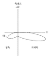
도 2는 본 개시내용의 양태에 따른, 조명 기구 아래의 수평 평면에서 도 1의 조명 기구에 의해 생성된 배광 패턴을 도시하는 칸델라 다이어그램이다.
도 3은 본 개시내용의 양태에 따른, 조명 기구를 교차하는 수직 평면에서 도 1의 조명 기구에 의해 생성된 배광 패턴을 도시하는 칸델라 다이어그램이다.
도 4는 본 개시내용의 양태에 따른, 도 1의 조명 기구의 평면도이다.
도 5는 일 가능한 구성에 따른, 도 1의 조명 기구에 사용될 수 있는 광 가이드 조립체의 예의 측단면도이다.
도 6은 다른 가능한 구성에 따른, 도 1의 조명 기구에 사용될 수 있는 광 가이드 조립체의 예의 측단면도이다.
도 7은 본 개시내용의 양태에 따른, LED 스트립의 예의 다이어그램이다.
도 8은 본 개시내용의 양태에 따른, LED 스트립의 예의 다이어그램이다.
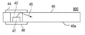
도 9는 본 개시내용의 양태에 따른, 광 가이드의 예의 다이어그램이다.
도 10은 본 개시내용의 양태에 따른, 도 9의 광 가이드를 포함하는 광 가이드 조립체의 부분의 측단면도이다.
도 11은 본 개시내용의 양태에 따른, 광 가이드 조립체의 예의 측단면도이다.
도 12는 본 개시내용의 양태에 따른, 도 11의 광 가이드 조립체의 평단면도이다.
도 13은 본 개시내용의 양태에 따른, 광 가이드 조립체의 예의 측단면도이다.
도 14는 본 개시내용의 양태에 따른 광 가이드 조립체의 예의 측단면도이다.
도 15는 본 개시내용의 양태에 따른, 도 14의 광 가이드 조립체의 평단면도이다.
도 16은 본 개시내용의 양태에 따른, 광 가이드 조립체의 예의 측단면도이다.
도 17은 본 개시내용의 양태에 따른, 광 가이드 조립체의 예의 측단면도이다.
도 18은 본 개시내용의 양태에 따른, 광 가이드 조립체의 예의 측단면도이다.
도 19a는 본 개시내용의 양태에 따른, 광 가이드 조립체의 예의 평면도이다.
도 19b는 본 개시내용의 양태에 따른, 도 19a의 광 가이드 조립체의 예의 측면도이다.
도 20a는 본 개시내용의 양태에 따른, 광 가이드의 예의 평면도이다.
도 20b는 본 개시내용의 양태에 따른, 도 20a의 광 가이드 조립체의 측면도이다.
도 21a는 본 개시내용의 양태에 따른, 광 가이드 조립체의 예의 평면도이다.
도 21b는 본 개시내용의 양태에 따른, 도 21a의 광 가이드 조립체의 측면도이다.
도 22a는 본 개시내용의 양태에 따른, 광 가이드 조립체의 예의 평면도이다.
도 22b는 본 개시내용의 양태에 따른, 도 22a의 광 가이드 조립체의 측면도이다.
도 23은 본 개시내용의 양태에 따른, 광 가이드 조립체의 예의 평면도이다.
도 24는 본 개시내용의 양태에 따른, 광 가이드 조립체의 예의 평면도이다.
도 25는 본 개시내용의 양태에 따른, 광 가이드 조립체의 예의 평면도이다.
도 26은 본 개시내용의 양태에 따른, 광 가이드 조립체의 예의 평면도이다.
도 27은 본 개시내용의 양태에 따른, 광 가이드 조립체의 예의 측면도이다.
도 28은 본 개시내용의 양태에 따른, 광 가이드 조립체의 예의 측면도이다.
도 29는 본 개시내용의 양태에 따른, 광 가이드 조립체의 예의 측면도이다.
도 30은 본 개시내용의 양태에 따른, 광 가이드 조립체의 예의 측면도이다.
도 31은 본 개시내용의 양태에 따른, 광 가이드 조립체의 예의 측면도이다.
도 32는 본 개시내용의 양태에 따른, 광 가이드 조립체의 예의 측면도이다.
도 33은 본 개시내용의 양태에 따른, 광 가이드 조립체의 예의 측단면도이다.
도 34는 본 개시내용의 양태에 따른, 광 가이드 조립체의 예의 측단면도이다.
도 35는 본 개시내용의 양태에 따른, 광 가이드 조립체의 예의 측단면도이다.
도 36은 본 개시내용의 양태에 따른, 광 가이드 조립체의 예의 측단면도이다.
도 37은 본 개시내용의 양태에 따른, 광 가이드 조립체의 예의 측단면도이다.
도 38은 본 개시내용의 양태에 따른, 광 가이드 조립체의 예의 측단면도이다.
도 39는 본 개시내용의 양태에 따른, 광 가이드의 예의 측단면도이다.
도 40은 본 개시내용의 양태에 따른, 광 가이드의 예의 측단면도이다.
도 41은 본 개시내용의 양태에 따른, 광 가이드의 예의 측단면도이다.
도 42는 본 개시내용의 양태에 따른, 광 가이드의 예의 측단면도이다.
도 43은 본 개시내용의 양태에 따른, 광 가이드의 예의 측단면도이다.
도 44는 본 개시내용의 양태에 따른, 광 가이드의 예의 측단면도이다.
도 45는 본 개시내용의 양태에 따른, 광 가이드의 예의 측단면도이다.
도 46은 본 개시내용의 양태에 따른, 광 가이드의 예의 측단면도이다.
도 47은 본 개시내용의 양태에 따른, 광 가이드의 예의 측단면도이다.
도 48은 본 개시내용의 양태에 따른, 광 가이드의 예의 측단면도이다.
도 49는 본 개시내용의 양태에 따른, 광 가이드의 예의 측단면도이다.
도 50은 본 개시내용의 양태에 따른, 광 가이드의 예의 측단면도이다.The drawings described below are for illustrative purposes only. The drawings are not intended to limit the scope of the present disclosure. Like reference numerals in the drawings denote like parts in various embodiments.
1 is a perspective view of an example of a luminaire according to an aspect of the present disclosure;
Figure 2 is a candela diagram illustrating the light distribution pattern produced by the lighting fixture of Figure 1 in a horizontal plane below the lighting fixture, in accordance with an aspect of the present disclosure;
3 is a candela diagram illustrating a light distribution pattern produced by the lighting fixture of FIG. 1 in a vertical plane intersecting a lighting fixture, in accordance with an aspect of the present disclosure;
Figure 4 is a plan view of the luminaire of Figure 1, in accordance with aspects of the present disclosure;
5 is a side cross-sectional view of an example of a light guide assembly that may be used in the luminaire of Fig. 1, in accordance with a possible configuration.
Figure 6 is a side cross-sectional view of an example of a light guide assembly that may be used in the luminaire of Figure 1, according to another possible configuration.
Figure 7 is a diagram of an example of an LED strip, in accordance with aspects of the present disclosure.
Figure 8 is a diagram of an example of an LED strip, in accordance with aspects of the present disclosure.
9 is a diagram of an example of a light guide, in accordance with aspects of the present disclosure;
10 is a side cross-sectional view of a portion of a light guide assembly including the light guide of FIG. 9, in accordance with aspects of the present disclosure;
11 is a side cross-sectional view of an example of a light guide assembly, in accordance with aspects of the present disclosure;
12 is a top cross-sectional view of the light guide assembly of FIG. 11, in accordance with an aspect of the present disclosure;
13 is a side cross-sectional view of an example of a light guide assembly, in accordance with aspects of the present disclosure;
14 is a side cross-sectional view of an example of a light guide assembly in accordance with aspects of the present disclosure;
Figure 15 is a top cross-sectional view of the light guide assembly of Figure 14, in accordance with an aspect of the present disclosure;
16 is a side cross-sectional view of an example of a light guide assembly, in accordance with aspects of the present disclosure;
17 is a side cross-sectional view of an example of a light guide assembly, in accordance with aspects of the present disclosure;
18 is a side cross-sectional view of an example of a light guide assembly, in accordance with aspects of the present disclosure;
19A is a plan view of an example of a light guide assembly, in accordance with aspects of the present disclosure;
19B is a side view of an example of the light guide assembly of FIG. 19A, in accordance with aspects of the present disclosure;
20A is a plan view of an example of a light guide, in accordance with aspects of the present disclosure;
20B is a side view of the light guide assembly of FIG. 20A, in accordance with aspects of the present disclosure;
21A is a top view of an example of a light guide assembly, in accordance with aspects of the present disclosure;
21B is a side view of the light guide assembly of FIG. 21A, in accordance with aspects of the present disclosure;
22A is a plan view of an example of a light guide assembly, in accordance with aspects of the present disclosure;
Figure 22B is a side view of the light guide assembly of Figure 22A, in accordance with aspects of the present disclosure;
23 is a top view of an example of a light guide assembly, in accordance with aspects of the present disclosure;
24 is a top view of an example of a light guide assembly, in accordance with aspects of the present disclosure;
25 is a top view of an example of a light guide assembly, in accordance with aspects of the present disclosure;
26 is a top view of an example of a light guide assembly, in accordance with aspects of the present disclosure;
Figure 27 is a side view of an example of a light guide assembly, in accordance with aspects of the present disclosure;
28 is a side view of an example of a light guide assembly, in accordance with aspects of the present disclosure;
29 is a side view of an example of a light guide assembly, in accordance with aspects of the present disclosure;
30 is a side view of an example of a light guide assembly, in accordance with aspects of the present disclosure;
31 is a side view of an example of a light guide assembly, in accordance with aspects of the present disclosure;
32 is a side view of an example of a light guide assembly, in accordance with aspects of the present disclosure;
33 is a side cross-sectional view of an example of a light guide assembly, in accordance with aspects of the present disclosure;
34 is a side cross-sectional view of an example of a light guide assembly, in accordance with aspects of the present disclosure;
35 is a side cross-sectional view of an example of a light guide assembly, in accordance with aspects of the present disclosure;
36 is a side cross-sectional view of an example of a light guide assembly, in accordance with aspects of the present disclosure;
37 is a side cross-sectional view of an example of a light guide assembly, in accordance with aspects of the present disclosure;
38 is a side cross-sectional view of an example of a light guide assembly, in accordance with aspects of the present disclosure;
39 is a side cross-sectional view of an example of a light guide, in accordance with aspects of the present disclosure;
40 is a side cross-sectional view of an example of a light guide, in accordance with aspects of the present disclosure;
41 is a side cross-sectional view of an example of a light guide, in accordance with aspects of the present disclosure;
Figure 42 is a side cross-sectional view of an example of a light guide, in accordance with an aspect of the present disclosure;
43 is a side cross-sectional view of an example of a light guide, in accordance with aspects of the present disclosure;
44 is a side cross-sectional view of an example of a light guide, in accordance with aspects of the present disclosure;
45 is a side cross-sectional view of an example of a light guide, in accordance with aspects of the present disclosure;
46 is a side cross-sectional view of an example of a light guide, in accordance with aspects of the present disclosure;
47 is a side cross-sectional view of an example of a light guide, in accordance with aspects of the present disclosure;
48 is a side cross-sectional view of an example of a light guide, in accordance with aspects of the present disclosure;
49 is a side cross-sectional view of an example of a light guide, in accordance with aspects of the present disclosure;
50 is a side cross-sectional view of an example of a light guide, in accordance with aspects of the present disclosure;
본 개시내용의 양태에 따르면, 감소된 섬광 및 스폿성을 갖고, 비대칭 배광 패턴을 생성하기 위해 고가의 2차 광학계를 필요로 하지 않는 LED 기반 조명 기구가 개시된다. 감소된 섬광 및 스폿성은 표준 성형 렌즈 어레이 대신에 광 가이드 광학계를 사용함으로써 달성된다. 광 가이드 광학계는 또한 조명 기구의 외관에 영향을 미치지 않고, 조명 기구의 배광 패턴을 변경하기 위해 교체 인입 및 인출될(swapped in and out) 수 있다.According to an aspect of the present disclosure, an LED-based luminaire having reduced flashing and spotting properties and requiring no expensive secondary optical system to produce an asymmetric light distribution pattern is disclosed. Reduced flashing and spots are achieved by using a light guide optical system instead of a standard molded lens array. The optical waveguide optical system may also be swapped in and out to change the light distribution pattern of the luminaire without affecting the appearance of the luminaire.
본 개시내용의 양태에 따르면, 실질적으로 균일한 확산 광 외관을 생성할 수도 있는 가로등 용례에 사용을 위한 광 가이드가 개시된다. 이는 각각의 LED(예를 들어, 각각 8개의 2개의 열로 배열된 16개의 LED를 갖는 라이트)에 대한 개별 광학계를 갖는 LED 어레이를 사용하는 가로등과는 대조된다. 이러한 가로등은 직접 볼 때 높은 섬광을 가질 수도 있다. 더욱이, 이들 가로등은 관찰자에 의해 종종 미관적으로 매력이 없는 것으로 판명된 픽셀화된 광 패턴을 생성한다.In accordance with an aspect of the present disclosure, a light guide for use in a streetlight application that may produce a substantially uniform diffused light appearance is disclosed. This contrasts with the streetlamps using LED arrays with separate optics for each LED (e.g., a light with 16 LEDs arranged in each of eight columns). These street lights can have high flashes when viewed directly. Moreover, these streetlights produce a pixilated light pattern that is often found by the observer to be unattractively attractive.
본 개시내용의 양태에 따르면, 조명 기구 광 가이드 광학계는 그 외부면을 성형 및/또는 텍스처링하고 원하는 배광 패턴을 생성하기 위해 사출 성형 프로세스를 필요로 하지 않을 수도 있다. 이는 예를 들어, 교외의 가로등, 코너 조명 및 교차로 조명과 같은 상이한 가로등 용례에 적합하도록 상이한 배광 패턴을 제공하는 다양한 유사한 외관의 조명 기구를 공급하기 위해 상당히 저가가 되게 할 수 있다.In accordance with an aspect of the present disclosure, the illuminator optical waveguide optical system may not require an injection molding process to shape and / or texturize its outer surface and produce a desired light distribution pattern. This can make it considerably inexpensive to provide a variety of similar exterior lighting fixtures that provide different light distribution patterns, for example, for different street lamp applications such as suburban street lights, corner lights and intersection lighting.
본 개시내용의 양태에 따르면, 광 가이드 조립체로부터 방출된 광에 방향성을 부여하는 상이한 특징을 구비하는 광 가이드 조립체가 개시된다. 이러한 특징은 광 가이드의 형상, 광 가이드 상에 인쇄된 가우시안 도트(Gaussian dots), 광 가이드 상에 성형된 프리즘, 광 가이드 상에 성형되거나 에칭된 홈 및/또는 랜덤 표면 거칠기를 포함할 수도 있다. 이들 특징의 결과로서, 광 가이드 조립체는 특정 분배 패턴을 달성하기 위해 2차 광학계에 의존하지 않을 수도 있다. 그럼에도 불구하고, 광 가이드 조립체는 요구되면 2차 광학계와 함께 또한 사용될 수도 있다.SUMMARY OF THE INVENTION In accordance with an aspect of the present disclosure, a light guide assembly is disclosed that has different features that direct light emitted from the light guide assembly. This feature may include the shape of the light guide, the Gaussian dots printed on the light guide, the prism formed on the light guide, the grooved or etched groove on the light guide, and / or the random surface roughness. As a result of these features, the light guide assembly may not rely on the secondary optical system to achieve a particular distribution pattern. Nevertheless, the light guide assembly may also be used with a secondary optical system if desired.
본 개시내용의 양태에 따르면, 다양한 조명 용례에 사용을 위한 광 가이드가 개시된다. 광 가이드는 투명 또는 반투명 재료로 형성된 슬레이트일 수도 있다. 슬레이트는 복수의 에지 및 2개의 표면을 가질 수도 있다. 광 가이드에 의한 대부분의 광 출력은 표면들 중 하나 이상을 통해 광 가이드를 출사할 수도 있다. 이에 따라, 광이 방출되는 표면들 중 임의의 표면은 광 출사면이라 칭할 수도 있다. 몇몇 구현예에서, 일 표면은 지정된 광 출사면을 향해 광을 반사하기 위한 반사기를 구비할 수도 있다.According to aspects of the present disclosure, a light guide for use in various illumination applications is disclosed. The light guide may be a slate formed of a transparent or translucent material. The slate may have a plurality of edges and two surfaces. Most light output by the light guide may exit the light guide through one or more of the surfaces. Accordingly, any surface among the surfaces on which light is emitted may be referred to as a light exit surface. In some embodiments, one surface may have a reflector for reflecting light towards a designated light exit surface.
본 개시내용의 양태에 따르면, 비대칭 배광 패턴을 생성하기 위해 최적화된 광 가이드가 개시된다. 광 가이드는 경사진 측면 에지를 갖는 전방부 및 직선형 측면 에지를 갖는 전방부를 특징으로 한다. 경사진 측면 에지의 각각은 직선형 측면 에지 중 상이한 하나를 만날 수도 있다. 본 개시내용의 양태에 따르면, 경사진 측면 에지들 중 임의의 측면 에지와 소정의 직선형 측면 에지 사이의 각도는 광 가이드의 광 출력의 어느 부분이 특정 방향으로 지향되는지를 결정한다. 본 개시내용에 따르면, 이 각도를 130도 내지 160도 사이에서 변동하는 것은 광 가이드로부터의 광 출력의 원하는 방향성을 부여하기 위해 실용적인 것으로 판명되었다.According to an aspect of the present disclosure, a light guide optimized for producing an asymmetric light distribution pattern is disclosed. The light guide is characterized by a front portion with a sloping side edge and a front portion with a straight side edge. Each of the sloped side edges may meet a different one of the straight side edges. According to an aspect of the present disclosure, the angle between any of the side edges of the sloped side edges and the predetermined straight side edge determines which portion of the light output of the light guide is oriented in a particular direction. According to the present disclosure, varying this angle between 130 degrees and 160 degrees has proven to be practical for imparting the desired directionality of light output from the light guide.
본 개시내용의 양태에 따르면, 복수의 LED 및 광 가이드를 포함하는 광 가이드 조립체가 개시된다. 광 가이드는 그 코너가 절단된 직사각형으로서 성형될 수도 있는데; 이는 둔각으로 그 사이에 배치된 후방 에지를 만나는 2개의 경사진 에지를 가질 수도 있다. 조명 기구 내의 LED가 경사진 에지와 그 사이의 후방 에지에 집중될 때, 광 가이드는 LED가 정방향으로 그 광 출력의 더 큰 부분을 방출하게 할 수도 있다.According to an aspect of the present disclosure, a light guide assembly comprising a plurality of LEDs and a light guide is disclosed. The light guide may be shaped as a rectangle whose corner is cut; It may have two oblique edges that meet the rear edge disposed therebetween at an obtuse angle. When the LEDs in the luminaire are focused on the beveled edge and the back edge therebetween, the light guide may cause the LED to emit a larger portion of its light output in the normal direction.
몇몇 양태에서, 광의 하나 이상의 표면은 광 가이드로부터 광의 추출을 용이하게 하기 위해 복수의 가우시안 도트를 구비할 수도 있다. 몇몇 구현예에서, 표면상의 임의의 위치에서의 가우시안 도트의 밀도는 그 위치와 전방 에지 사이의 거리에 비례할 수도 있다. 거리가 작을수록 밀도가 높아진다. 이하에 더 설명되는 바와 같이, 광 가이드의 전방 에지 부근에 더 많은 가우시안 도트를 집중시키는 것은 정방향에서 광 추출을 용이하게 할 수도 있다.In some aspects, one or more surfaces of the light may have a plurality of Gaussian dots to facilitate extraction of light from the light guide. In some implementations, the density of the Gaussian dots at any location on the surface may be proportional to the distance between that location and the front edge. The smaller the distance, the higher the density. As described further below, concentrating more Gaussian dots near the forward edge of the lightguide may facilitate light extraction in the forward direction.
본 개시내용의 양태에 따르면, 고도의 가요성 디자인을 특징으로 하는 광 가이드 조립체가 개시된다. 광 가이드 조립체는 광 가이드(예를 들어, 투명 또는 반투명 슬레이트) 및 광 가이드의 에지 중 적어도 일부에 있는 LED 스트립을 포함할 수도 있다. 광 가이드 조립체의 배광 패턴은 광 가이드 주위에 감긴 LED 스트립의 타입 및/또는 길이를 간단히 변경함으로써 조정될 수도 있다. 이에 따라, 소정의 광 가이드의 에지 주위에 감겨진 LED 스트립을 변경함으로써 다수의 상이한 배광 패턴이 달성될 수도 있다.SUMMARY OF THE INVENTION According to an aspect of the present disclosure, a light guide assembly is disclosed that features a highly flexible design. The light guide assembly may include a light guide (e.g., a transparent or translucent slate) and an LED strip at least a portion of the edge of the light guide. The light distribution pattern of the light guide assembly may be adjusted by simply changing the type and / or length of the LED strip wound around the light guide. Accordingly, a plurality of different light distribution patterns may be achieved by changing the LED strips wound around the edge of a given light guide.
본 개시내용의 양태에 따르면, 후방부를 포함하는 광 가이드로서, 후방부는 제1 에지, 제2 에지 및 후방 에지를 포함하고, 제1 에지는 제1 둔각에서 후방 에지와 만나고, 제2 에지는 제2 둔각에서 후방 에지와 만나는, 광 가이드; 및 제1 에지, 제2 에지 및 후방 에지 상에 배치된 복수의 발광 다이오드(LED)로서, 복수의 LED는 후방 발광 및 후방 발광보다 더 큰 피크 강도를 갖는 전방 발광을 포함하는 비대칭 배광 패턴을 생성하도록 배열되는, 복수의 발광 다이오드(LED)를 포함하는 장치가 개시된다.According to an aspect of the present disclosure there is provided a light guide comprising a rear portion, the rear portion including a first edge, a second edge and a rear edge, wherein the first edge meets a rear edge at a first obtuse angle, 2 light guide, which meets the rear edge at an obtuse angle; And a plurality of light emitting diodes (LEDs) disposed on the first edge, the second edge, and the back edge, wherein the plurality of LEDs generate an asymmetric light distribution pattern including forward light emission having greater peak intensity than back light emission and back light emission A device comprising a plurality of light emitting diodes (LEDs) arranged to emit light.
본 개시내용의 양태에 따르면, 지지 구조체; 지지 구조체에 결합된 하우징; 상기 하우징 내에 배열되는 광 가이드 - 상기 광 가이드는 균일한 폭의 전방부 및 후방 테이퍼부를 포함하고, 상기 전방부는 상기 지지 구조체로부터 외면하는 전방 에지를 포함하고, 상기 후방부는 상기 지지 구조체를 향해 대면하는 후방 에지를 포함함 - ; 및 상기 지지 구조체로부터 멀어지게 지향되는 전방 발광 및 상기 지지 구조체를 향해 지향되는 후방 발광을 적어도 갖는 비대칭 배광을 생성하기 위해 상기 광 가이드의 후방부의 둘레 주위에 장착된 복수의 발광 다이오드(LED) - 상기 전방 발광은 상기 후방 발광보다 더 큰 피크 강도를 가짐 -를 포함하는 장치가 개시된다.According to an aspect of the present disclosure, there is provided a lithographic apparatus comprising: a support structure; A housing coupled to the support structure; A light guide arranged in the housing, the light guide including a front portion and a backward taper portion of uniform width, the front portion including a front edge facing away from the support structure, the rear portion facing toward the support structure A back edge; And a plurality of light emitting diodes (LEDs) mounted around a periphery of a rear portion of the light guide to produce an asymmetrical light distribution having at least a front light directed away from the support structure and a back light directed toward the support structure, Wherein the front emission has a greater peak intensity than the back emission.
본 개시내용의 양태에 따르면, 직사각형 형상인 전방부 및 사다리꼴 형상인 후방부를 갖는 발광면을 포함하는 광 가이드; 발광면의 후방부와 만나는 광 가이드의 하나 이상의 에지에 결합된 복수의 LED - 복수의 LED는 후방 발광 및 후방 발광보다 더 큰 피크 강도를 갖는 전방 발광을 포함하는 배광 패턴을 생성하도록 배열됨 -를 포함하는 장치가 개시된다.According to an aspect of the present disclosure, there is provided a light guide comprising a light-emitting surface having a rectangular front portion and a trapezoidal rear portion; A plurality of LEDs coupled to at least one edge of a light guide that meets the rear of the light emitting surface, the plurality of LEDs being arranged to produce a light distribution pattern comprising forward emission having greater peak intensity than backlight and backlight A device comprising the same is disclosed.
상이한 조명 디바이스의 예가 첨부 도면을 참조하여 이하에 더 상세히 설명될 것이다. 이들 예는 상호 배타적인 것이 아니며, 일 예에서 발견된 특징은 하나 이상의 다른 예에서 발견된 특징과 조합되어 부가의 구현예를 달성할 수 있다. 이에 따라, 첨부 도면에 도시된 예는 단지 예시의 목적으로 제공된 것이고, 본 개시내용을 결코 한정하도록 의도된 것은 아니라는 것이 이해될 수 있을 것이다. 동일한 도면 부호는 전체에 걸쳐 동일한 요소를 지칭한다.Examples of different illumination devices will be described in more detail below with reference to the accompanying drawings. These examples are not mutually exclusive, and features found in one example may be combined with features found in one or more other examples to achieve additional embodiments. Accordingly, it is to be understood that the example shown in the accompanying drawings is provided for illustrative purposes only, and is not intended to limit the present disclosure in any way. Like reference numerals refer to like elements throughout.
용어 제1, 제2 등은 본 명세서에서 다양한 요소를 설명하기 위해 사용될 수도 있지만, 이들 요소는 이들 용어에 의해 한정되어서는 안된다는 것이 이해될 수 있을 것이다. 이들 용어는 하나의 요소를 다른 요소와 구별하기 위해서만 사용된다. 예를 들어, 본 발명의 범주로부터 벗어나지 않고, 제1 요소는 제2 요소로 명명될 수 있고, 유사하게, 제2 요소는 제1 요소로 명명될 수 있다. 본 명세서에 사용될 때, 용어 "및/또는"은 연관된 열거된 항목 중 하나 이상의 임의의 및 모든 조합을 포함한다.The terms first, second, etc. may be used herein to describe various elements, but it should be understood that these elements should not be limited by these terms. These terms are only used to distinguish one element from another. For example, without departing from the scope of the present invention, a first element can be named a second element, and similarly, a second element can be named a first element. As used herein, the term " and / or " includes any and all combinations of one or more of the associated listed items.
층, 영역 또는 기판과 같은 요소가 다른 요소의 "위에" 있거나 다른 구성요소 "위로" 연장하는 것으로 언급될 때, 이는 다른 요소 바로 위에 있거나 바로 위로 연장할 수 있고 또는 개재 요소가 또한 존재할 수도 있다는 것이 이해될 수 있을 것이다. 대조적으로, 요소가 다른 요소에 "바로 위에" 있거나 또는 "바로 위로" 연장하는 것으로 언급될 때, 개재 요소는 존재하지 않는다. 요소가 다른 요소에 "연결"또는 "결합"되는 것으로 언급될 때, 요소는 다른 요소에 직접 연결되거나 결합될 수 있고, 또는 개재 요소가 존재할 수도 있다는 것이 또한 이해될 수 있을 것이다. 대조적으로, 요소가 다른 요소에 "직접 연결" 또는 "직접 결합"되는 것으로 언급될 때, 개재 요소는 존재하지 않는다. 이들 용어는 도면에 도시된 임의의 배향에 추가하여 요소의 상이한 배향을 포함하도록 의도된다는 것이 이해될 수 있을 것이다.It is to be understood that when an element such as a layer, region or substrate is referred to as being "on" or "over" another element, it may be directly on top of or directly above another element, It can be understood. In contrast, when an element is referred to as being "directly over" or "directly over" another element, the intervening element is not present. It will also be appreciated that when an element is referred to as being " connected " or " coupled " to another element, the element may be directly connected or coupled to another element, or intervening elements may be present. In contrast, when an element is referred to as being " directly connected " or " directly coupled " to another element, there is no intervening element. It will be appreciated that these terms are intended to encompass different orientations of the elements in addition to any orientation shown in the figures.
"아래" 또는 "위" 또는 "상부" 또는 "하부" 또는 "수평" 또는 "수직"과 같은 상대 용어는 도면에 도시된 바와 같이 다른 요소, 층 또는 영역에 대한 하나의 요소, 층 또는 영역의 관계를 설명하기 위해 본 명세서에서 사용될 수도 있다. 이들 용어는 도면에 도시된 배향에 추가하여 디바이스의 상이한 배향을 포함하도록 의도된 것이라는 것이 이해될 수 있을 것이다.Relative terms such as "below" or "above" or "upper" or "lower" or "horizontal" or "vertical" May be used herein to describe the relationship. It will be appreciated that these terms are intended to encompass different orientations of the device in addition to the orientation shown in the figures.
도 1은 본 개시내용의 양태에 따른, 조명 기구(10)의 예의 사시도이다. 조명 기구(10)는 거리(14) 위에 지지 구조체(12)에 의해 지지된다. 거리를 대면하는 조명 기구(10)의 전방측은 본 명세서에서 "거리측"이라 칭한다. 반대 방향으로 대면하는 조명 기구의 후방측은 본 명세서에서 "집측"이라 칭한다. 이 명명법 하에서, 광이 정방향으로 출력될 때, 이는 거리측 방향으로 방출된다고 일컫는다. 유사하게, 광이 역방향으로 출력될 때, 이는 집측 방향으로 방출된다고 일컫는다. 그리고 광이 측방향으로(예를 들어, 좌측 및/또는 우측 방향으로) 출력될 때, 이는 거리를 따라 방출된다고 일컫는다.1 is a perspective view of an example of a
본 예에 따르면, 조명 기구(10)는 타입 II 비대칭 배광 패턴을 갖는다. 이는 거리의 특정 길이를 따라 높은 광 강도, 거리측 방향에서 더 낮은 광 강도, 및 집측 방향에서 훨씬 더 낮은 광 강도를 제공하도록 구성된다. 몇몇 경우에, 조명 기구(10)는 더 큰 가로등 시스템의 부분일 수도 있다. 거리의 길이를 따른 광은 인접한 가로등으로부터의 광과 혼합되어 전체 거리의 균일한 조명을 제공할 수도 있다.According to this example, the
도 2는 본 개시내용의 양태에 따른, 조명 기구 아래의 수평 평면(예를 들어, 거리(14)의 평면)에서 조명 기구(10)에 의해 생성된 배광 패턴을 도시하는 칸델라 다이어그램이다. 도 3은 본 개시내용의 양태에 따른, 조명 기구를 교차하는 수직 평면에서 조명 기구(10)에 의해 생성된 배광 패턴을 도시하는 칸델라 다이어그램이다. 도시된 예에서, 거리(14)를 따라 지향된 피크 광 강도는 거리측 방향으로 생성되는 피크 광 강도보다 약 2 내지 3배 더 높다. 더욱이, 집측 방향에서의 피크 광 강도는 이웃 부동산에 광 침해를 최소화하기 위해 거리측 방향에서의 광 강도의 3분의 1 미만이다. 즉시 이해될 수 있는 바와 같이, 집측 방향으로 방출되는 임의의 광은 거리를 따른 인도를 조명하기 위해 또는 조명 기구가 거리에 양호하게 현수되어 경우 연석 지역을 조명하기 위해 사용될 수도 있다.2 is a candela diagram illustrating the light distribution pattern produced by the
도 4는 본 개시내용의 양태에 따른, 조명 기구(10)의 평면도이다. 본 예에서 조명 기구(10)의 커버(도시되지 않음)는 조명 기구의 내부 구조를 드러내기 위해 제거되어 있다. 커버 아래에서, 조명 기구(10)는 광 가이드(24)를 수용하도록 배열된 원형 금속 프레임(20)을 포함한다. 몇몇 구현예에서, LED 스트립과 같은 가요성 회로 테이프(도시되지 않음)가 광 가이드(24)의 에지와 프레임(20) 사이에 배치될 수도 있다. 가요성 회로 테이프는 프레임(20)의 내주부 주위에 배치될 수도 있고 LED의 선형 어레이를 포함할 수도 있다.4 is a plan view of a
몇몇 구현예에서, 프레임(20)은 직경이 약 15 인치일 수도 있고, 약 168개의 LED를 포함할 수도 있다. 몇몇 구현예에서, 가요성 LED 회로 테이프는 공유 전원에 직렬 또는 병렬로 접속된 12개의 세그먼트로 분할될 수 있다. 몇몇 구현예에서, 광 가이드(24)는 PMMA와 같은 투명 폴리머로 형성될 수도 있고, 두께가 약 4 내지 5 mm일 수도 있다. 부가적으로 또는 대안적으로, 몇몇 구현예에서, 광 가이드(24)는 그 위에 인쇄된 복수의 가우시안 도트(26)를 가질 수도 있다.In some embodiments, the
반사기 시트(도시되지 않음)가 광 가이드(24) 및 LED 위에 위치되어 거리(14)를 향해 광을 반사할 수도 있다. 반사기 시트는 정반사성 또는 약간 확산성 미러 시트일 수도 있고, 광선의 방향성을 실질적으로 유지할 수도 있고 조명 기구(10)의 배광 패턴에 대해 더 양호한 제어를 제공할 수 있다. 부가적으로 또는 대안적으로, 몇몇 구현예에서, 반사기 시트는 더 많은 램버시안(Lambertian) 배광 패턴에 대한 광의 확산을 더 증가시키기 위한 백색 표면을 가질 수도 있다. 반사기 시트는 광 가이드(24)로부터 이격되거나 또는 직접 맞접할 수도 있다.A reflector sheet (not shown) may be positioned over the
도 5는 조명 기구(10)에 사용될 수 있는 광 가이드 조립체(500)의 예의 측단면도이다. 본 예에서, 가우시안 도트(26)는 광 가이드(24)의 광 출사면(24a)(예를 들어, 거리(14)를 대면하는 표면) 상에 인쇄된다. 게다가, LED(30)는 LED 스트립(32) 상의 광 가이드(24)의 둘레 주위에 제공되고, 반사기 시트(28)가 광 가이드(24)의 내부면(24b) 상에 제공된다. 광선(34)은 반사기 시트(28)를 향해 그리고/또는 광 가이드(24)의 외부로 가우시안 도트(26)에 의해 방출된다.5 is a side cross-sectional view of an example of a
몇몇 양태에서, 가우시안 도트(26)는 바람직한 배광 패턴을 달성하기 위해 입사광을 확산성/방향성 방식으로 재지향할 수도 있다. 가우시안 도트(26)는 1 mm 정도의 직경을 가질 수도 있다. 부가적으로 또는 대안적으로, 몇몇 구현예에서, 가우시안 도트는 1 mm 이하로 피칭될(pitched) 수도 있다. 이러한 경우에, 조명 기구(10)는 가우시안 도트(26) 사이의 밀접한 근접도로 인해 관찰자에게 균일하게 백색으로 보일 수도 있다.In some embodiments, the
몇몇 구현예에서, 가우시안 도트(26)는 스크린 인쇄 및/또는 임의의 다른 적합한 인쇄 기술을 사용하여 잉크로 인쇄될 수도 있다. 부가적으로 또는 대안적으로, 가우시안 도트(26)는 에폭시계 또는 실리콘계일 수도 있고, SiO2, TiO2, 또는 고굴절률 마이크로 비드와 같은 확산 입자를 포함할 수도 있다. 이러한 경우, 가우시안 도트(26)는 LED(30)에 의해 방출된 광을 단지 약간 확산시킬 수도 있다. 예를 들어, 이들 가우시안 도트는 충돌하는 광선의 방향에 집중된, 약 12도의 반치전폭(full-width half-maximum: HWHM)을 갖는 패턴으로 광을 확산시킬 수도 있다.In some implementations, the
도 6은 본 개시내용의 양태에 따른, 조명 기구(10)에 사용될 수 있는 광 가이드 조립체(600)의 예의 측단면도이다. 도시된 바와 같이, 광 가이드 조립체(600)에서, 가우시안 도트(26)는 광 가이드(24)의 내부면(24b) 상에 인쇄된다. 가우시안 도트(26)에 의해 상향으로 재지향되는 임의의 광은 반사기 시트(28)에 의해, 광 가이드(24)의 광 출사면(24a)을 향해 반사된다. 몇몇 구현예에서, 표면(24a)은 조명 기구(10)의 배광 패턴을 더 조절하기 위해 그 위에 형성된 확산층을 가질 수도 있다. 몇몇 구현예에서, 확산층은 적층 시트를 포함할 수도 있다. 부가적으로 또는 대안적으로, 몇몇 구현예에서, 확산층은 광 가이드(24)를 기계 가공 또는 성형함으로써 형성될 수도 있다. 부가적으로 또는 대안적으로, 몇몇 구현예에서, 다른 방향성 추출 요소가 광 가이드(24) 상에 포함될 수도 있다. 이러한 추출 요소는 광 가이드(24) 상에 직접 성형된 적층 시트 또는 프리즘 상에 형성된 광학 요소를 포함할 수도 있다.FIG. 6 is a side cross-sectional view of an example of a
도 7은 조명 기구(10)에 사용될 수 있는 LED 스트립(700)의 예의 다이어그램이고, 도 8은 조명 기구(10)에 또한 사용될 수 있는 LED 스트립(800)의 예의 다이어그램이다. LED 스트립(700)은 제1 피치로 배열된 LED(37)를 포함한다. 다른 한편으로, LED 스트립(800)은 제1 피치보다 큰 제2 피치로 배열된 LED(38)를 포함한다. 따라서 조명 기구(10)는 그 광원으로서 임의의 특정 타입의 LED 또는 LED 스트립을 사용하는 것에 한정되지 않는다. LED 및/또는 LED 스트립의 타입은 설계 사양 및/또는 원하는 배광 패턴에 따라 케이스별로 선택될 수 있다.7 is a diagram of an example of an
조명 기구(10)의 하우징은 둥근형이지만, 다양한 형상 및/또는 상이한 타입의 광원(예를 들어, LED 스트립, 개별 LED 등)의 광 가이드를 수용하도록 구성될 수도 있다. 예를 들어, 조명 기구(10)의 하우징은 원형, 직사각형인 광 가이드, 및/또는 각형성된 코너를 갖는 광 가이드를 수용하도록 구성될 수도 있다. 더 구체적으로, 조명 기구(10)는 도 9 및 도 50과 관련하여 설명된 임의의 광 가이드를 수용하도록 구성될 수도 있다. 상이한 타입의 광 가이드에 대해 동일한(또는 유사한) 하우징을 제공하는 것은 조명 기구(10)가 사용되는 조명 시스템의 전체 비용을 감소시키면서, 균일한 미적 외관을 생성할 수도 있다.The housing of the
본 예에서 조명 기구(10)는 둥근 형상을 갖지만, 조명 기구(10)의 하우징이 직사각형 형상 및/또는 임의의 다른 적합한 형상을 갖는 대안 구현예가 가능하다. 더욱이, 본 예에서 조명 기구(10)는 타입 II의 배광을 제공하도록 구성되었지만, 조명 기구(10)가 예를 들어 타입 III 또는 타입 IV 배광과 같은 임의의 바람직한 분배를 갖도록 구성되는 대안 구현예가 가능하다. 조명 기구(10)의 배광 패턴은 그 내부에 배치된 광 가이드 조립체를 교체함으로써 변경될 수도 있다. 이하에 더 설명되는 바와 같이, 광 가이드 조립체가 특정 분배 패턴을 달성하기 위해 요구되는 모든 광 추출 특징(예를 들어, 특정 형상을 갖는 광 가이드 조립체, 가우시안 도트, 프리즘, 특정 방향으로 배향된 LED 등)을 포함할 수도 있기 때문에, 이러한 것이 가능하다.In this example, the
몇몇 양태에서, 조명 기구(10)는 더 큰 가로등 시스템의 부분일 수도 있다. 가로등 시스템은 모두 동일한 하우징을 갖는 복수의 조명 기구를 포함할 수도 있다. 몇몇 양태에서, 조명 기구 사이의 간격은 조명 기구의 배광 패턴에 의존할 수도 있다. 측방향으로 방출되는 광의 강도가 클수록, 간격이 더 크다. 더욱이, 몇몇 경우에, 그러나, 조명 기구의 적어도 일부는 상이한 배광 패턴을 가질 수도 있다. 예를 들어, 거리 코너에 위치된 조명 기구는 타입 V 분배 패턴을 가질 수도 있고, 반면에 거리 블록의 중간에 위치된 조명 기구는 타입 III 분배 패턴을 가질 수도 있다. 상이한 배광 패턴에 대한 추가의 정보는 ["Lighting for Exterior Environments," RP-33 published by the Illuminating Engineering Society of North America.]에서 발견될 수 있다.In some aspects, the
도 9는 본 개시내용의 양태에 따른, 광 가이드(40)의 예의 평면도이고, 도 10은 광 가이드(40)를 포함하는 광 가이드 조립체(900)의 부분의 측단면도이다. 도시된 바와 같이, 광 가이드(40)는 그 둘레 주위에 형성된 리세스(42)를 포함할 수도 있다. 리세스(42)는 관통 구멍 또는 막힌 구멍(blind hole)일 수도 있다. 각각의 리세스(42)는 도시된 바와 같이, LED 스트립(48) 내에 상이한 LED(47)를 수용하도록 배열될 수도 있다. 반사링(44)이 리세스(42) 위에 배치될 수도 있다. 링(44)은 백색, 정반사성, 확산 반사성 및/또는 임의의 다른 적합한 타입의 반사링일 수도 있다. 반사링(44)은 광선(45)과 같은 광선을 광 가이드(40)의 광 출사면(40a)을 향해 반사시키도록 동작 가능할 수도 있다.FIG. 9 is a plan view of an example of a
도 11은 본 개시내용의 양태에 따른, 광 가이드 조립체(1100)의 예의 측단면도이고, 도 12는 광 가이드 조립체(1100)의 평단면도이다. 도시된 바와 같이, 광 가이드 조립체(1100)는 광 가이드(52)의 에지에 결합된 하나 이상의 LED(50)를 포함할 수도 있다. 반사기(55)는 도시된 바와 같이, LED(50) 위 및/또는 아래에 배치될 수도 있다. LED(50)를 광 가이드(52)의 에지에 결합하는 것은 광선(54)의 도시에 의해 지시된 바와 같이, 광의 좁은 빔이 광 가이드(52) 내로 유도되게 할 수 있다.11 is a side cross-sectional view of an example of a
도 13은 본 개시내용의 양태에 따른, 광 가이드 조립체(1300)의 예의 측단면도이다. 도시된 바와 같이, 광 가이드 조립체(1300)는 광 가이드(52)의 에지(52a)에 결합된 LED(50)를 포함할 수도 있다. LED(50)는 광 가이드(52)의 표면(52b)의 평면을 대면하도록 배열될 수도 있고, LED(50)를 지지하는 가요성 회로(56)가 광 가이드(52)의 표면(52c)과 동일 높이에 있을 수도 있다. 만곡형 반사기(58)가 도시된 바와 같이, LED(50) 위에 배치될 수도 있다. 반사기(58)는 제1 단부 및 제2 단부를 가질 수도 있다. 도시된 바와 같이, 제1 단부는 가요성 회로(56)와 동일한 평면에 놓일 수도 있고, 제2 단부는 표면(52b)과 중첩될 수도 있다.13 is a side cross-sectional view of an example of a
도 14는 본 개시내용의 양태에 따른, 광 가이드 조립체(1400)의 예의 측단면도이고, 도 15는 광 가이드 조립체(1400)의 평단면도이다. 도시된 바와 같이, 광 가이드 조립체(1400)는 광 가이드의 표면(57a)에 형성된 리세스(59)를 갖는 광 가이드(57)를 포함할 수도 있다. 리세스(59)는 도시된 바와 같이, 광 가이드(57)의 에지(57b)에 인접하여 형성될 수도 있다. 몇몇 구현예에서, 리세스(59)는 LED(50)만을 수용하기에 충분히 큰 둥근 구멍일 수도 있다. 부가적으로 또는 대안적으로, 몇몇 구현예에서, 리세스(59)는 에지(57b)를 따라 연장하는 슬롯일 수도 있다. 이러한 경우에, 다수의 LED를 포함하는 전체 LED 스트립이 슬롯 내에 배치될 수도 있다. 부가적으로 또는 대안적으로, 몇몇 구현예에서, 슬롯은 실질적으로 에지(57b)의 전체 길이를 따라 연장할 수도 있다(예를 들어, 전체 길이의 90% 이상).14 is a side cross-sectional view of an example of a
반사기(51)가 LED(50) 위에 배치될 수도 있다. 몇몇 구현예에서, 반사기(51)는 광 가이드(57)의 상부면(57c)이 반사기(51)의 상부면과 동일 높이가 되도록, 광 가이드(57)의 상부면(57c)에 형성된 리세스 내에 배치될 수도 있다. 몇몇 구현예에서, 반사기(51)가 배치되는 리세스는 실질적으로 리세스(59) 위에 형성될 수도 있다. 부가적으로 또는 대안적으로, 몇몇 구현예에서, 반사기(51)가 배치되는 리세스는 광 가이드(57)의 부분(57d)에 의해 리세스(59)로부터 분리될 수도 있다.The
몇몇 양태에서, LED(50)는 그 베이스가 광 가이드의 주 표면에 평행한 상태로, 광 가이드(57) 내에 배치되기 때문에, 광선(53)의 도시에 의해 도시된 바와 같이, 광 가이드(57) 내로 360° 방출을 생성할 수도 있다. 이는, 광 가이드(52)의 에지들 중 하나 이상을 대면하도록 배향되는 결과로서 좁은 방출을 생성하는 LED(50)(광 가이드 조립체(1100)의)와 대조된다. 이와 관련하여, 광의 에지 주입(광 가이드 조립체(1100) 내에서와 같은)은 매립형 주입(광 가이드 조립체(1400)에서와 같은)보다 더 방향성 광 방출을 생성한다는 것이 다시 주목되어야 한다. 이에 따라, 광 가이드의 에지 및 표면을 향해 배향되는 LED의 수 및 위치를 변동함으로써, 상이한 비대칭 배광 패턴이 달성될 수 있다.The
도 16은 본 개시내용의 양태에 따른, 광 가이드 조립체(1600)의 예의 측단면도이다. 그리고, 도 17은 본 개시내용의 양태에 따른, 광 가이드 조립체(1700)의 예의 측단면도이다. 광 가이드 조립체(1600, 1700)는 라운딩된 에지를 갖는 광 가이드를 각각 포함한다. 그러나, 조립체(1600)의 광 가이드(62)는 조립체(1700)의 광 가이드(64)를 제조하는 데 사용된 재료와는 상이한 굴절률을 갖는 재료로 형성된다. 그 결과, 광 가이드(62)의 라운딩된 에지(62a)는 광 가이드(64)의 라운딩된 에지(64a)보다 더 많은 광을 반사하는 것이 가능하다.16 is a side cross-sectional view of an example of a
더 구체적으로, 조립체(1600)는 라운딩된 에지(62a) 및 직선형 에지(62b)를 갖는 광 가이드(62)를 포함한다. 리세스(61)는 광 가이드(62)의 하부면(62c)의 라운딩된 에지(62a)에 인접하여 형성된다. LED(60)가 리세스(61) 내에 배치되고 광 가이드(62)의 상부면(62d)을 대면하도록 배열된다. 전술된 바와 같이, 광 가이드(62)의 에지(62a)는 LED(60)로부터 광 가이드(62)의 표면(62d)을 향해 방출된 광을 반사시키도록 라운딩된다. 도시된 바와 같이, LED(60)에 의해 방출된 광선(63)은 도시된 바와 같이, 에지(62a)로부터 반사되어 광 출사면(62c)으로 복귀될 수도 있다. 본 개시내용의 양태에 따르면, 에지(62a)의 곡률 반경은 광 가이드 조립체(1600)가 원하는 배광 패턴에 따라 선택될 수 있다.More specifically,
리세스(61)는 임의의 적합한 타입의 구멍을 포함할 수도 있다. 예를 들어, 몇몇 구현예에서, 리세스(61)는 단일 LED를 수용하도록 크기 설정된 둥근형(또는 직사각형) 구멍일 수도 있다. 부가적으로 또는 대안적으로, 몇몇 구현예에서, 리세스(61)는 에지(62a)의 길이를 따라 연장하는 슬롯일 수도 있다. 이러한 경우에, 다수의 LED를 포함하는 전체 LED 스트립이 슬롯 내에 배치될 수도 있다. 부가적으로 또는 대안적으로, 몇몇 구현예에서, 슬롯은 실질적으로 에지(62a)의 전체 길이(예를 들어, 전체 길이의 90% 이상을 따라)로 연장할 수도 있다. 부가적으로 또는 대안적으로, 몇몇 구현예에서, 광 출사면(62c)을 향해 광선(63)을 반사시키기 위해 반사 필름이 표면(62d) 상에 배치될 수도 있다.The
광 가이드 조립체(1700)는 라운딩된 에지(64a) 및 직선형 에지(64b)를 갖는 광 가이드(64)를 포함한다. 리세스(61)가 라운딩된 에지(64a)에 인접하여 형성되고, LED(60)가 그 내에 배치된다. 도시된 바와 같이, 광 가이드(64)는 LED(60)에 의해 방출된 광선(63)이 라운딩된 에지(64a)를 통해 출사되게 하는 굴절률을 갖는 재료로 형성될 수도 있다. 이에 따라, 광 가이드 조립체(1700)는 더 큰 후면 방출(back emission)을 필요로 하는 용례에서 광 가이드 조립체(1600)에 비해 바람직할 수도 있다.The
도 18은 본 개시내용의 양태에 따른, 광 가이드 조립체(1800)의 예의 측단면도이다. 광 가이드 조립체(1800)는 도 9 및 도 10과 관련하여 설명된 광 조립체(900)와 실질적으로 유사하다. 그러나, 도 18의 광 조립체에서, 부가의 LED(65)가 조립체의 광 출력을 증가시키거나 광 출력에 상이한 색 성분 추가하기 위해 리세스(42)에 설치된다. 예를 들어, LED(65)는 (백색광) LED(30)를 보충하고 광 가이드 조립체에 의한 광 출력을 더 따뜻하게 하도록 배열된 적색 LED일 수도 있다. 몇몇 구현예에서, 적색 LED는 (백색광) LED(30)와는 별도로 제어될 수도 있다. 이러한 경우에, 조립체의 광 출력의 색 온도는 그 동작 중에 동적으로 변동될 수도 있다.18 is a side cross-sectional view of an example of a
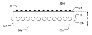
도 19a는 본 개시내용의 양태에 따른, 광 가이드 조립체(1900)의 예의 평면도이고, 도 19b는 광 가이드 조립체(1900)의 측면도이다. 조립체는 광 가이드(66) 및 광 가이드(66)의 후방부에 결합되는 복수의 LED(68)를 포함한다. 몇몇 양태에서, 광 가이드 조립체는 도 1과 관련하여 설명된 바와 같이, 가로등 용례에서 사용될 수도 있다.19A is a plan view of an example of a
몇몇 구현예에서, 광 가이드(66)는 5 mm와 동일한 두께(t)를 가질 수도 있고, 이는 PMMA와 같은 투명 또는 반투명 폴리머로 형성될 수도 있다. 가우시안 도트(26)는 도시된 바와 같이, 표면(66e, 66f) 중 적어도 하나 상에 인쇄될 수도 있다. 가우시안 도트(26)는 광 가이드의 직시(direct view)가 실질적으로 균일한 밝기를 갖게 하는 패턴으로 인쇄될 수도 있다. 몇몇 구현예에서, 패턴은, 광 가이드 출사면에서 직접 보았을 때 실질적으로 균일한 밝기 외관을 생성하기 위해 가우시안 도트의 밀도가 후방 에지(66a)로부터 거리에 따라 증가하는 패턴일 수도 있다. 이러한 경우에, 가우시안 도트(26)는 후방 에지(66a) 부근에서보다 전방 에지(66d) 부근에서 더 큰 밀도를 가질 것이다.In some embodiments, the
부가적으로 또는 대안적으로, 몇몇 구현예에서, 광 가이드(66)는 예를 들어 프리즘과 같은, 다른 타입의 방향성 광 추출 특징을 구비할 수도 있다. 부가적으로 또는 대안적으로, 몇몇 구현예에서, 광 가이드(66)는 랜덤 거칠기와 같은, 비방향성 광 추출 특징을 구비할 수도 있다. 몇몇 양태에서, 비방향성 광 추출 특징에 의해 불균일한 배광 패턴을 달성하는 것이 더 어려울 수도 있기 때문에, 방향성 광 추출 특징이 비방향성 광 추출 특징에 비해 바람직할 수도 있다.Additionally or alternatively, in some implementations, the
몇몇 구현예에서, LED(68)는 YAG 인광체(황색광 방출)와 조합된 청색광을 방출하여 백색광을 생성하는 GaN계 LED 다이를 사용하는 백색광 LED를 포함할 수도 있다. 부가적으로 또는 대안적으로, 몇몇 구현예에서, 적색 인광체가 첨가되어 CRI를 개선시킬 수도 있다. 광 가이드가 PMMA이고 LED 외부층이 실리콘 바인더 내의 YAG 인광체와 같은 실리콘인 경우, LED와 광 가이드 사이의 공기 갭은 굴절률의 다양한 차이에 기인하는 개선된 주입 효율을 위해 남아 있을 수도 있다.In some embodiments, the
플롯(77)은 광 가이드 조립체(1900)의 배광 패턴을 도시하고 있다. 더 구체적으로, 플롯(77)은 그래프(70, 72)를 포함한다. 그래프(70)는 광 가이드(66)의 표면(66f, 66e)과 정렬된 수평 평면에서 광 가이드 조립체(1900)에 의해 생성된 배광 패턴을 도시하고 있다. 그래프(72)는 조립체를 교차하는 수직 평면에서 광 가이드 조립체(1900)에 의해 생성된 배광 패턴을 도시하고 있다. 그래프(72)의 더 큰 로브(lobe)는 정방향에서 광 가이드 조립체(1900)에 의해 생성된 발광(예를 들어, 전방 발광)을 나타낸다. 그래프(72)의 더 작은 로브는 역방향에서 광 가이드 조립체(1900)에 의해 생성된 발광(예를 들어, 후방 발광)을 나타낸다.
더욱이, 좌측 및/또는 우측 방향에서 광 가이드 조립체(1900)의 발광(예를 들어, 측면 발광)는 정방향으로 생성된 발광의 적어도 2배인 피크 강도를 갖는다. 더욱이, 역방향에서의 발광의 피크 강도는 정방향에서의 발광의 피크 강도보다 작다. 간략하게 말하면, 광 가이드 조립체(1900)는 더 강한 전방 발광에 의해 특징화된 타입 II 배광 패턴을 생성하도록 배열되는데, 이는 광 가이드 조립체를 가로등 용례를 위해 적합하게 한다.Furthermore, the light emission (e.g., side emission) of the
본 개시내용의 양태에 따르면, 광 가이드(66)의 후방 에지(66a)를 따르는 LED(68)는 정방향으로 방출되는 대부분의 광을 공급한다. 더욱이, 측면 에지(66b, 66c)를 따르는 LED(68)는 측방향 및 역방향으로 지향되는 대부분의 광에 기여할 수도 있다. 후방 에지(66a)를 따라 또는 측면 에지(66b, 66c)를 따라 더 많은 LED를 추가함으로써, 조립체(1900)의 배광 패턴은 광 가이드(66) 자체를 변경하지 않고 가로등 사이의 특정 거리 폭 또는 피치에 정밀하게 맞춤화될 수 있다. 달리 말하면, 특정 용례에 적합하도록 조립체(1900)의 배광 패턴을 조정하기 위해 광 가이드의 후방부 주위에 부착된 가요성 회로 스트립 상의 LED 배열만이 변경될 필요가 있을 수도 있다. LED의 배열을 변경하는 것은 스트립의 단위 길이당 LED의 밀도를 변경하는 것, LED의 피치를 변경하는 것, 스트립에 사용되는 LED의 타입을 변경하는 것 등을 포함할 수도 있다.According to an aspect of the present disclosure, the
도 20a는 본 개시내용의 양태에 따른, 광 가이드 조립체(2000)의 예의 평면도이고, 도 20b는 광 가이드 조립체(2000)의 측면도이다. 도시된 바와 같이, 광 가이드 조립체(2000)는 광 가이드(76) 및 광 가이드(76)의 후방부에 결합된 복수의 LED(68)를 포함할 수도 있다. 본 예에서, 각각의 LED(68)가 광 가이드(76)의 후방부의 에지들 중 하나를 대면하지만(예를 들어, 도 11에 도시된 방식으로), LED(68) 중 하나 이상이 상향 또는 하향으로 배향되는(예를 들어, 도 13에 도시된 방식으로) 대안 구현예가 가능하다.20A is a plan view of an example of a
몇몇 구현예에서, 광 가이드(66)는 5 mm와 동일한 두께(t)를 가질 수도 있고, 이는 PMMA와 같은 투명 또는 반투명 폴리머로 형성될 수도 있다. 광 가이드의 후방부는 후방 에지(76a) 및 측면 에지(76b, 76c)를 포함한다. 후방 에지(76a)와 측면 에지(76b) 사이의 각도(A1)는 110도일 수도 있다. 후방 에지와 측면 에지(76c) 사이의 각도(A2)는 또한 110도일 수도 있다. 본 예에서 각도(A1, A2)는 동일하지만, 각도(A1, A2)가 상이한 대안 구현예가 가능하다.In some embodiments, the
광 가이드(76)의 전방부는 전방 에지(76d) 및 측면 에지(76e, 76f)를 포함한다. 몇몇 구현예에서, 각각의 측면 에지(76e, 76f)는 직각으로 전방 에지(76d)와 만날 수도 있다. 더욱이, 측면 에지(76b)와 측면 에지(76e) 사이의 각도(A3)는 160도와 동일할 수도 있다. 유사하게, 측면 에지(76c)와 측면 에지(76f) 사이의 각도(A4)는 160도와 동일할 수도 있다. 본 예에서 각도(A3, A4)는 동일하지만, 각도(A3, A4)가 상이한 대안 구현예가 가능하다. 본 예에서, 광 가이드 조립체의 전방부는 어떠한 LED도 포함하지 않지만, LED(68) 중 적어도 일부가 광 가이드(76)의 전방부에 배치되는 대안 구현예가 가능하다. 도시되지는 않았지만, 광 가이드(76)는 인쇄된 가우시안 도트와 같은 방향성 광 추출 특징을 그 표면(들) 상에 포함할 수도 있다.The front portion of the
플롯(79)은 광 가이드 조립체(2000)의 배광 패턴을 도시하고 있다. 더 구체적으로, 플롯(79)은 그래프(72, 78, 80)를 포함한다. 그래프(78)는 광 가이드(76)의 표면(76g, 76h)과 정렬되는 수평 평면에서 광 가이드 조립체(2000)에 의해 생성된 배광 패턴을 도시하고 있다. 그래프(80)는 조립체(2000)를 교차하는 수직 평면에서 광 가이드 조립체(2000)에 의해 생성된 배광 패턴을 도시하고 있다. 그래프(72)는 조립체(1900)를 교차하는 수직 평면에서 광 가이드 조립체(1900)에 의해 생성된 배광 패턴을 도시하고 있다. 그래프(80)의 더 큰 로브는 정방향에서 광 가이드 조립체(2000)에 의해 생성된 발광(예를 들어, 전방 발광)을 나타낸다. 그래프(80)의 더 작은 로브는 역방향에서 광 가이드 조립체에 의해 생성된 발광(예를 들어, 후방 발광)을 나타낸다. 도시된 바와 같이, 광 가이드 조립체(2000)는 후방 발광 및 후방 발광보다 큰 전방 발광을 포함하는 타입 III 배광 패턴을 생성하도록 배열된다.The
본 예에 따르면, 광 가이드 조립체(2000)는 광 가이드 조립체(1900)보다 적은 광을 방출한다. 이는 광 가이드 조립체(2000)가 광 가이드 조립체(1900)보다 적은 수의 LED를 포함하기 때문에 그러하다. 그러나, 광 가이드 조립체(2000)는 광 가이드 조립체(1900)보다 정방향으로 그 광 출력의 더 많은 부분을 출력한다. 이는 측면 에지(76b, 76c)가 후방 에지(76a)에 대해 둔각으로 위치된 결과이다. 더욱이, 그래프(80)에 의해 도시된 바와 같이, 정방향으로 방출되는 광의 피크 강도는 역방향으로 방출되는 광의 피크 강도보다 클 수도 있다.According to this example, the
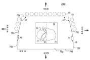
도 21a는 본 개시내용의 양태에 따른, 광 가이드 조립체(2100)의 예의 평면도이고, 도 21b는 광 가이드 조립체(2100)의 측면도이다. 광 가이드 조립체(2100)는 그 후방 코너가 더 각형성되어 있는 점에서 광 가이드 조립체(2000)는 상이하다. 이하에 더 설명되는 바와 같이, 광 가이드의 전방부의 측면 에지와 후방부의 측면 에지 사이의 각도(예를 들어, 각도(B3) 및/또는 각도(B4))를 증가시키는 것은 광 가이드 조립체(2100)가 광 가이드 조립체(2000)보다 정방향으로 그 광 출력의 더 많은 부분을 방출하게 할 수도 있다.21A is a plan view of an example of a
몇몇 양태에서, 광 가이드의 전방부 및 후방부의 측면 에지 사이의 각도를 130도 내지 160도로 변동하는 것은 광 가이드의 전방 발광의 피크 강도를 제어하기 위한 실용적인 방법일 수도 있다.In some embodiments, varying the angle between the front and rear side edges of the light guide to 130 to 160 degrees may be a practical method for controlling the peak intensity of the front emission of the light guide.
광 가이드 조립체(2100)는 광 가이드(86) 및 광 가이드(86)의 후방부에 결합된 복수의 LED(68)를 포함한다. 본 예에서, 각각의 LED(68)가 광 가이드(86)의 후방부의 에지들 중 하나를 대면하지만(예를 들어, 도 11에 도시된 방식으로), LED(68) 중 하나 이상이 상향 또는 하향으로 배향되는(예를 들어, 도 13에 도시된 방식으로) 대안 구현예가 가능하다.The
몇몇 구현예에서, 광 가이드(86)는 5 mm와 동일한 두께(t)를 가질 수도 있고, 이는 PMMA와 같은 투명 또는 반투명 폴리머로 형성될 수도 있다. 광 가이드의 후방부는 후방 에지(86a) 및 측면 에지(86b, 86c)를 포함한다. 후방 에지(86a)와 측면 에지(86b) 사이의 각도(B1)는 125도와 동일할 수도 있다. 후방 에지(86a)와 측면 에지(86c) 사이의 각도(B2)는 또한 125도와 동일할 수도 있다. 본 예에서 각도(B1, B2)는 동일하지만, 각도(B1, B2)가 상이한 대안 구현예가 가능하다.In some embodiments, the
광 가이드 조립체(2100)는 전방부를 더 포함한다. 전방부는 전방 에지(86d) 및 측면 에지(86e, 86f)를 포함할 수도 있다. 몇몇 구현예에서, 측면 에지(86e, 86f)는 직각으로 전방 에지(86d)와 만날 수도 있다. 더욱이, 측면 에지(86e)와 측면 에지(86b) 사이의 각도(B3)는 145도와 동일할 수도 있다. 에지(86f)와 측면 에지(86c) 사이의 각도(B4)는 또한 145도와 동일할 수도 있다. 본 예에서 각도(B3, B4)는 동일하지만, 각도(B3, B4)가 상이한 대안 구현예가 가능하다. 본 예에서 광 가이드(86)의 전방부에 어떠한 LED도 위치되어 있지 않지만, 하나 이상의 LED가 에지(86d, 86e, 86f) 중 적어도 하나에 결합되는 대안 구현예가 가능하다.The
플롯(87)은 광 가이드 조립체(2100)의 배광 패턴을 도시하고 있다. 더 구체적으로, 플롯(87)은 그래프(88, 90, 72)를 포함한다. 그래프(88)는 광 가이드(86)의 표면(86g, 86h)과 정렬된 수평 평면에서 광 가이드 조립체(2100)에 의해 생성된 배광 패턴을 도시하고 있다. 그래프(90)는 조립체(2100)를 교차하는 수직 평면에서 광 가이드 조립체(2100)에 의해 생성된 배광 패턴을 도시하고 있다. 그래프(72)는 조립체(1900)를 교차하는 수직 평면에서 광 가이드 조립체(1900)에 의해 생성된 배광 패턴을 도시하고 있다. 그래프(90)의 더 큰 로브는 정방향에서 광 가이드 조립체(2100)에 의해 생성된 발광(예를 들어, 전방 발광)을 나타낸다. 그래프(90)의 더 작은 로브는 역방향에서 광 가이드 조립체에 의해 생성된 발광(예를 들어, 후방 발광)을 나타낸다. 도시된 바와 같이, 광 가이드 조립체(2100)는 후방 발광 및 후방 발광보다 큰 전방 발광을 포함하는 타입 IV 배광 패턴을 생성하도록 배열된다.The
광 가이드 조립체(2100)의 배광 패턴은 정방향에서 넓은 발광(예를 들어, 전방 발광) 및 역방향에서 비교적 좁은 발광(예를 들어, 후방 발광)에 의해 특징화된다. 정방향의 발광은 그래프(90)의 더 큰 로브에 의해 표현되고, 역방향에서의 발광은 그래프(90)의 더 작은 로브에 의해 표현된다. 도시된 바와 같이, 정방향에서의 피크 광 강도는 역방향에서의 피크 광 강도보다 상당히 클 수도 있다. 몇몇 양태에서, 광 가이드 조립체의 전방 발광은 비교적 넓고 균일하기 때문에, 도 21의 조명 기구는 오버헤드 재배용 라이트로서 원예 용도에 적합할 수도 있다. 이러한 경우, LED(68)는 성장에 최적인 색(들)을 가질 수도 있다.The light distribution pattern of the
몇몇 양태에서, 각도(B3, B4)의 크기는 광 가이드 조립체(2100)의 배광 패턴에 영향을 미칠 수도 있다. 그래프(90) 및 그래프(80)(도 20에 도시됨)에 의해 도시된 바와 같이, 광 가이드 조립체의 전방부 및 후방부의 각각의 측면 에지 사이의 각도(B3, B4)의 크기가 감소될 때, 더 많은 광이 광 가이드(86)의 전방을 향해 지향되고 궁극적으로 정방향으로 방출된다. 또한, 몇몇 구현예에서, 광 가이드(86)의 배광 패턴은 인쇄된 가우시안 도트와 같은 방향성 광 추출 특징을 그 표면(들) 상에 포함함으로써 조절될 수도 있다. 더욱이, 광 가이드(86)의 배광 패턴은 광 가이드(86)의 후방부에 배치된 LED의 피치 및 수를 신중하게 선택함으로써 조절될 수도 있다.In some aspects, the magnitude of the angles B3, B4 may affect the light distribution pattern of the
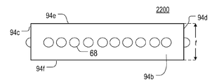
도 22a는 본 개시내용의 양태에 따른, 광 가이드 조립체(2200)의 예의 평면도이고, 도 22b는 광 가이드 조립체(2200)의 측면도이다. 광 가이드 조립체(2200)는 광 가이드(94)의 에지(94a, 94b, 94c, 94d) 상에 균일하게 분포된 복수의 LED(68)에 결합된 광 가이드(94)를 포함한다. 본 예에서, 각각의 LED(68)가 광 가이드(94)의 에지들 중 하나를 대면하지만(예를 들어, 도 11에 도시된 방식으로), LED(68) 중 하나 이상이 상향 또는 하향으로 배향되는(예를 들어, 도 13에 도시된 방식으로) 대안 구현예가 가능하다.22A is a plan view of an example of a
몇몇 구현예에서, 광 가이드(94)는 5 mm와 동일한 두께(t)를 가질 수도 있고, 이는 PMMA와 같은 투명 또는 반투명 폴리머로 형성될 수도 있다. 플롯(97)은 광 가이드 조립체(2200)의 배광 패턴을 도시하고 있다. 더 구체적으로, 플롯(97)은 그래프(96, 98)를 포함한다. 그래프(96)는 광 가이드(94)의 표면(94e, 94f)과 정렬된 수평 평면에서 광 가이드 조립체(2200)에 의해 생성된 배광 패턴을 도시하고 있다. 그래프(98)는 조립체(2200)를 교차하는 수직 평면에서 광 가이드 조립체(2200)에 의해 생성된 배광 패턴을 도시하고 있다. 도시된 바와 같이, 광 가이드 조립체(2200)는 모든 방향에서 실질적으로 균일한 강도에 의해 특징화되는 타입 V 배광 패턴을 생성하도록 배열된다.In some implementations, the
본 개시내용의 양태에 따르면, 광 가이드 조립체 중 임의의 것은 광 가이드 조립체(1900 내지 2200)가 더 큰 조명 시스템(예를 들어, 가로등 시스템)에 사용될 때 일관적인 외관을 달성하도록 동일한 조명 기구 하우징 내에 배치될 수도 있다. 소정의 조명 시스템에서, 가이드 광 조립체 중 임의의 것이 각각의 배광 패턴을 위해 가장 적합한 위치에 전개될 수도 있다. 예를 들어, 광 가이드 조립체(2100)는 조용한 거주 지역(그 감소된 후방 발광으로 인해)에 바람직한 것으로 간주될 수도 있고, 반면 광 가이드 조립체(1900)는 상가 거리(더 큰 후방 발광으로 인해)에 바람직한 것으로 간주될 수도 있다.In accordance with an aspect of the present disclosure, any of the light guide assemblies may be disposed within the same luminaire housing (e.g., a streetlight system) to achieve a consistent appearance when the light guide assemblies 1900-2200 are used in a larger illumination system . In a given illumination system, any of the guide light assemblies may be deployed in a position most suitable for each light distribution pattern. For example,
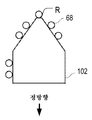
또한, 도 23 내지 도 26은 본 개시내용의 양태에 따른, 다양한 광 가이드 조립체의 평면도를 도시하고 있다. 광 가이드 조립체는 원하는 배광 패턴을 달성하기 위해 상이한 위치에서 에지 주위에 LED가 위치되어 있는, 상이한 형상의 광 가이드(100 내지 103)를 각각 포함한다. 도 23 내지 도 26에 도시된 광 가이드 조립체는 일반적으로 이들의 각각의 광 가이드의 후방측(R)으로부터 이격하여 광을 지향시킨다. 광 가이드(100 내지 103) 중 임의의 것의 후방측(R)이 벽에 대해 위치될 때, 그 광 가이드는 정방향으로 벽으로부터 이격하여 광을 방출할 것이다. 간략하게 말하면, 도 23 내지 도 36에 도시된 광 가이드 조립체는 더 많은 광이 후방 방향보다 정방향으로 방출되는 비대칭 배광 패턴을 생성한다. 전술된 바와 같이, 도 24에 도시된 광 가이드 조립체는 가로등 용례에 적합한 타입 IV 배광을 생성할 수 있다.23-26 also show plan views of various light guide assemblies, in accordance with aspects of the present disclosure. The light guide assemblies each include light guides 100-103 of different shapes, with the LEDs positioned around the edges at different locations to achieve the desired light distribution pattern. The light guide assemblies shown in FIGS. 23-26 generally direct light away from the rear side R of each of these light guides. When the rear side R of any of the light guides 100-103 is positioned relative to the wall, the light guide will emit light away from the wall in a positive direction. Briefly, the light guide assembly shown in Figs. 23-36 produces an asymmetric light distribution pattern in which more light is emitted in a more positive direction than the backward direction. As described above, the light guide assembly shown in Fig. 24 can produce a Type IV light distribution suitable for street lamp applications.
본 개시내용의 양태에 따르면, 광 가이드 조립체는 광 가이드 상의 특정 위치에 LED를 전략적으로 배치함으로써 특정 배광 패턴을 갖도록 구성될 수도 있다. 전술된 바와 같이, LED가 광 가이드의 에지 상에(예를 들어, 에지 상에 형성된 구멍에) 배치될 때, 광 가이드는 결과적으로 비교적 좁은 방향성 빔을 방출할 수도 있다. 대조적으로, LED가 광 가이드의 표면 중 하나 상에 배치될 때, 광 가이드는 넓은(예를 들어, 360°) 방출을 생성할 수도 있다. 이에 따라, 광 가이드의 에지 및/또는 표면 상의 상이한 위치에 LED를 배치함으로써, 상이한 배광 패턴이 달성될 수 있다.According to an aspect of the present disclosure, the light guide assembly may be configured to have a specific light distribution pattern by strategically placing the LEDs at specific locations on the light guide. As described above, when the LED is placed on the edge of the light guide (e.g., in the aperture formed on the edge), the light guide may eventually emit a relatively narrow directional beam. In contrast, when the LED is placed on one of the surfaces of the light guide, the light guide may produce a broad (e.g., 360) emission. Thus, by disposing the LEDs at different positions on the edge and / or surface of the light guide, different light distribution patterns can be achieved.
도 27 내지 도 38은 본 개시내용의 양태에 따른, LED가 조립체의 각각의 광 가이드 상의 상이한 위치에 배치되어 있는 광 가이드 조립체의 상이한 예를 도시하고 있다. 도 27 내지 도 32에 도시된 광 가이드 조립체의 각각은 조립체의 광 가이드에 에지 결합된(예를 들어, 도 27 내지 도 30 및 도 32 참조), 광 가이드에 공동 결합된(예를 들어, 도 32 참조), 또는 광 가이드의 주 표면 중 하나에 결합된(예를 들어, 도 29 및 도 31 참조) 하나 이상의 LED(68)를 포함한다. LED(68)가 광 가이드에 에지-결합될 때, 그 LED(68)는 광 가이드의 에지에 인접하여 부착되어, LED(68)로부터 방출된 광이 광 가이드의 에지를 통해 광 가이드에 진입하게 되고, 이어서 광 가이드가 더 많은 방향성 배광 패턴을 생성하게 한다. 유사하게, LED(68)가 광 가이드의 주 표면에 결합될 때, 그 LED는 광 가이드의 주 표면에 인접하여 부착되어, LED(68)로부터 방출된 광이 그 표면을 통해 광 가이드에 진입하게 되고, 이어서 또한 광 가이드가 더 많은 방향성 배광 패턴을 생성하게 한다.Figures 27-38 illustrate different examples of light guide assemblies in which LEDs are disposed at different locations on each light guide of the assembly, in accordance with aspects of the present disclosure. Each of the light guide assemblies shown in Figs. 27-32 may include a plurality of light guide assemblies (not shown) coupled edge to light guide (e.g., see Figs. 27-30 and 32) 32), or one or
대조적으로, LED(68)가 광 가이드에 공동 결합될 때, 그 LED(68)는 광 가이드에 형성된 리세스(또는 공동) 내에 배치된다. LED(68)로부터 방출된 광은 리세스(또는 공동)의 벽을 통해 모든 방향으로 광 가이드에 진입하고, 이는 광 가이드가 더 넓게 확산된 배광 패턴을 갖게 한다. 특히, 광 가이드의 리세스를 통해 광 가이드 내로 주입되는 광은 광 가이드의 에지를 통해 주입되는 광보다 더 높은 전파 속도를 가질 수도 있다. 간략하게 말하면, 도 27 내지 도 38에 관하여 제공된 예는 다양한 원하는 배광 패턴을 생성하는 광 가이드에 대한 LED(68)의 위치의 다양한 조합을 도시하고 있다.In contrast, when the
도 27은 광 가이드(106) 및 광 가이드(106)의 에지(106a, 106b, 106c) 상에 균일하게 분포된 복수의 LED(68)를 포함하는 광 가이드 조립체의 측면도이다.Figure 27 is a side view of a light guide assembly including a plurality of
도 28은 광 가이드(107) 및 복수의 LED(68)를 포함하는 광 가이드 조립체의 측면도이다. 도 28의 예에서, LED(68)는 광 가이드(107)의 에지(107a) 상에 비대칭으로 배열되어, 에지(107a)의 다른 단부보다 일 단부 부근에 더 많은 LED가 배치된다.28 is a side view of a light guide assembly including a
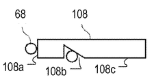
도 29는 광 가이드(108) 및 광 가이드 상에 배열된 복수의 LED(68)를 포함하는 광 가이드 조립체의 측면도이다. 본 예에 따르면, LED(68) 중 적어도 하나는 광 가이드의 에지(108a) 상에 위치될 수도 있다. 더욱이, 하나 이상의 LED가 광 가이드의 표면(108c) 상에 형성된 리세스(108b) 내에 배치될 수도 있다.29 is a side view of a light guide assembly including a
도 30은 광 가이드(109) 및 복수의 LED(68)를 포함하는 광 가이드 조립체의 측면도이다. 도 30의 예에서, 하나 이상의 LED(68)는 광 가이드(109)의 에지(109a, 109b) 상에 배치될 수도 있다. 게다가, 하나 이상의 LED(68)가 광 가이드(109)의 상부면(109c) 상에 배치될 수도 있다. 도시된 바와 같이, LED(68)는 상부면(109c)의 일 측면에 집중될 수도 있다. 전술된 바와 같이, 광 가이드(109)의 에지 및/또는 표면 상에 불균일한 패턴으로 LED를 분배하는 것은 광 조립체가 비대칭 배광 패턴을 갖게 할 수도 있다.30 is a side view of a light guide assembly including a
도 31은 광 가이드(110) 및 복수의 LED(68)를 포함하는 광 가이드 조립체의 측면도이다. 도 31의 예에서, LED(68) 중 하나 이상은 광 가이드(110)의 상부면(110a) 상에 배열될 수도 있다. 게다가, LED(68) 중 하나 이상은 광 가이드(110)의 하부면(110b) 상에 배열될 수도 있다.31 is a side view of a light guide assembly including a
도 32는 광 가이드(111) 및 복수의 LED(68)를 포함하는 광 가이드 조립체의 측면도이다. 도 32의 예에서, LED(68)는 광 가이드(111)의 에지(111a, 111b) 상에 배열된다.32 is a side view of a light guide assembly including a
도 33은 광 가이드(114) 및 복수의 LED(68)를 포함하는 광 가이드 조립체의 측단면도이다. 도 33의 예에서, 적어도 하나의 LED(68)가 광 가이드(114)의 에지(114a) 상에 배치될 수도 있다. 더욱이, 적어도 하나의 LED(68)가 광 가이드(114)의 하부면(114c)에 형성된 리세스(114b) 내에 배치될 수도 있다. 더욱이, 하나 이상의 LED가 광 가이드(114)에 형성된 관통 구멍(114d) 내에 배치될 수도 있다. 도시된 바와 같이, 리세스(114b)는 광 가이드(114)의 에지(114a)에 인접하여 형성될 수도 있다. 리세스(114b)는 임의의 적합한 형상을 가질 수도 있다. 몇몇 경우에, 리세스(114b)는 하나 이상의 LED(68)를 수용하도록 크기 설정된 원형 또는 직사각형 구멍을 포함할 수도 있다. 부가적으로 또는 대안적으로, 몇몇 구현예에서, 리세스(114b)는 에지(114a)를 따라 연장하는 슬롯일 수도 있다. 부가적으로 또는 대안적으로, 몇몇 구현예에서, 슬롯은 실질적으로 에지(114a)의 전체 길이를 따라(예를 들어, 전체 길이의 90% 이상) 연장할 수도 있다. 관통 구멍(114d)은 광 가이드(114)의 에지(114e)에 인접하여 형성될 수도 있다. 몇몇 경우에, 관통 구멍(114d)은 하나 이상의 LED(68)를 수용하도록 크기 설정된 원형 또는 직사각형 구멍 중 하나를 포함할 수도 있다.33 is a side cross-sectional view of a light guide assembly including a
도 34는 광 가이드(115) 및 복수의 LED(68)를 포함하는 광 가이드 조립체의 측단면도이다. 도 34의 예에서, LED(68) 중 적어도 하나는 광 가이드(115)의 표면(115b)에 형성된 리세스(115a) 내에 배치될 수도 있다. 게다가, 하나 이상의 LED가 광 가이드(115)의 에지(115c) 상에 배치될 수도 있다. 도시된 바와 같이, 리세스는 광을 에지(115d)의 방향으로 더 효율적으로 지향하기 위해 삼각형 단면을 가질 수도 있다.34 is a side cross-sectional view of a light guide assembly including a
도 35는 광 가이드(116) 및 복수의 LED(68)를 포함하는 광 가이드 조립체의 측단면도이다. 도 35의 예에서, 적어도 하나의 LED(68)가 광 가이드(116)의 에지(116a) 상에 배치될 수도 있다. 게다가, 하나 이상의 LED(68)가 표면(116c)에 형성된 리세스(116b) 내에 배치될 수도 있다. 또한, 하나 이상의 LED(68)는 광 가이드(116)의 에지(116e)에 인접하여 형성된 관통 구멍(116d) 내에 배치될 수도 있다. 본 개시내용의 양태에 따르면, 각각의 반사기(124)는 광 출사면(116c)을 향해 광을 반사하도록 광 가이드(116)의 표면(116f) 상의 리세스(116b) 및 관통 구멍(116d)의 각각 위에 배치될 수도 있다. 더욱이, 반사 필름(126)이 광을 에지(116a)의 방향으로 반사하도록 광 가이드(116)의 에지(116e) 상에 배치될 수도 있다.35 is a side cross-sectional view of a light guide assembly including a
도 36은 광 가이드(117) 및 복수의 LED(68)를 포함하는 광 가이드 조립체의 측단면도이다. 도 36의 예에서, 적어도 하나의 LED(68)는 광 가이드(117)의 표면(117b) 상에 형성된 리세스(117a) 내에 배치될 수도 있다. 게다가, 도시된 바와 같이, 하나 이상의 LED(68)가 에지(117c)와 반사기(127) 사이에 배치될 수도 있다. 게다가, 반사기(128)가 광 출사면(117d)을 향해 광을 지향하기 위해 표면(117b) 상에 배치될 수도 있다. 도시된 바와 같이, 반사기(127)는 제1 단부 및 제2 단부를 갖는다. 제1 단부는 반사기(128)와 맞접할 수도 있고 제2 단부는 표면(117d) 위로 돌출할 수도 있다.36 is a side cross-sectional view of a light guide assembly including a
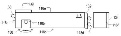
도 37은 광 가이드(118) 및 복수의 LED(68)를 포함하는 광 가이드 조립체의 측단면도이다. 도 37의 예에서, 하나 이상의 LED(68)가 광 가이드(118)의 에지(118a) 상에 배치될 수도 있다. 게다가, 하나 이상의 LED(68)는 에지(118a)에 인접하여 광 가이드(118)의 표면(118c)에 형성된 리세스(118b) 내에 배치될 수도 있다. 도시된 바와 같이, 렌즈(138)가 리세스(118b)의 개구 위에서, 표면(118c) 상에 배치될 수도 있고 반사기(139)가 리세스(118b) 위의 표면(118e) 상에 배치될 수도 있다.37 is a side cross-sectional view of a light guide assembly including a
더욱이, 하나 이상의 LED(68)가 에지(118f)에 인접하여 광 가이드(118)에 형성되는 관통 구멍(118d) 내에 배치될 수도 있다. 부분 반사기(132)가 관통 구멍(118d)의 내부벽 중 하나 이상에 결합될 수도 있다. 부분 반사기(132)는 나머지가 에지(118a)를 향해 이동하는 것을 허용하면서, 관통 구멍(118d) 내의 LED에 의해 방출된 광의 일부를 광 가이드(118)의 에지(118f)를 향해 반사시킬 수도 있다. 확산 반사기(134)가 또한 도시된 바와 같이, 에지(118a)를 향해 광을 반사하도록 에지(116e) 상에 배치될 수도 있다.Further, one or
도 38은 광 가이드(119) 및 복수의 LED(68)를 포함하는 광 가이드 조립체의 측단면도이다. 도 38의 예에서, 적어도 하나의 LED(68)가 광 가이드(119)의 표면(119b)에 형성된 리세스(119a) 내에 배치된다. 리세스(119a)는 삼각형 단면을 가질 수도 있다. 부분 반사기(140)가 에지(119d)의 방향으로 광을 반사시키도록 리세스(119a)의 경사진 내부벽 중 하나 이상 위에 배치될 수도 있고, 반면에 확산 반사기(142)가 리세스(119a)의 개구를 커버하도록 표면(119b) 상에 배치될 수도 있다. 부분 반사기(140)는 나머지가 반사기(140)를 가로질러 이동하게 하면서, LED에 의해 방출된 광의 일부를 반사시킬 수도 있다. 더욱이, 하나 이상의 LED가 도시된 바와 같이, 광 가이드(119)의 에지(119c) 상에 배치될 수도 있다.38 is a side cross-sectional view of a light guide assembly including a
몇몇 구현예에서, 상이한 색을 방출하는 LED가 광 가이드에서 조합되어 원하는 색 온도를 달성할 수도 있다. 부가적으로, 상이한 색 LED의 배치는, 정방향에서 더 차가운 백색 및 역방향에서 더 따뜻한 백색과 같이, 상이한 색 온도를 갖는 광이 광 가이드로부터 상이한 방향으로 방출되게 하는 데 사용될 수도 있다. 백색광 LED 및 적색 LED와 같은 다양한 상이한 색 LED는 광 가이드로부터의 방출의 색 온도를 상이한 방향으로 제어하기 위해 개별적으로 제어될 수 있다.In some implementations, LEDs emitting different colors may be combined in the lightguide to achieve the desired color temperature. Additionally, the arrangement of different color LEDs may be used to cause light having a different color temperature to be emitted in different directions from the light guide, such as a cooler white in the forward direction and a warmer white in the reverse direction. A variety of different color LEDs, such as a white light LED and a red LED, can be individually controlled to control the color temperature of the emission from the light guide in different directions.
도 39 내지 도 46은 본 개시내용의 양태에 따른, 광 가이드의 상이한 예의 측단면도이다. 도시된 바와 같이, 본 개시내용은 광 가이드의 임의의 특정 형상에 한정되지 않는다. 더 구체적으로, 도 49는 직사각형 단면을 갖는 광 가이드를 도시하고 있다. 도 49는 광 가이드의 하부면 아래로 연장하는 하나의 낫 형상의 단부를 갖는 광 가이드를 도시하고 있다. 특히, 도 49의 예는 본 개시내용 전체에 걸쳐 설명된 광 가이드 중 임의의 것이 가변 두께를 가질 수 있다는 것을 도시하고 있다.Figures 39-46 are side cross-sectional views of different examples of light guides, in accordance with aspects of the present disclosure; As shown, the present disclosure is not limited to any particular shape of the light guide. More specifically, FIG. 49 shows a light guide having a rectangular cross section. Figure 49 shows a light guide with one sickle-shaped end extending beneath the lower surface of the light guide. In particular, the example of Figure 49 illustrates that any of the light guides described throughout this disclosure may have varying thicknesses.
도 41은 그 하부면에 형성된 삼각형 리세스를 포함하는 광 가이드의 예를 도시하고 있다. 도 42는 상부면 및 하부면으로부터 연장하는 삼각형 돌기를 갖는 광 가이드의 예를 도시하고 있다. 도 43은 타원형 단면을 갖는 그 하부면에 형성된 리세스를 갖는 광 가이드의 예를 도시하고 있다. 도 44 및 도 49는 삼각형 단면을 갖는 광 가이드의 예를 도시하고 있다. 그리고 도 46은 아치형 단면을 갖는 광 가이드의 예를 도시하고 있다.Fig. 41 shows an example of a light guide including a triangular recess formed on the lower surface thereof. Figure 42 shows an example of a light guide having triangular protrusions extending from the top and bottom surfaces. Figure 43 shows an example of a light guide having a recess formed in its lower surface with an elliptical cross section. Figs. 44 and 49 show an example of a light guide having a triangular cross section. And Fig. 46 shows an example of a light guide having an arcuate cross section.
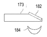
도 47 내지 도 50은 반사기 또는 렌즈와 같은 상이한 광학 요소와 함께 사용되는 광 가이드의 상이한 예의 측단면도이다. 더 구체적으로, 도 47은 그 상부면 상에 배치된 부분 반사기(176)를 갖는 광 가이드(170)의 예를 도시하고 있다. 도 48은 렌즈(178)와 함께 사용되는 광 가이드(171)의 예를 도시하고 있다. 도 49는 렌즈 어레이(180)와 함께 사용되는 광 가이드(172)의 예를 도시하고 있다. 그리고 도 50은 하나의 경사진 에지를 갖는 광 가이드(173)의 예를 도시하고 있다. 반사기(182)는 도시된 바와 같이 경사진 에지 상에 배치될 수도 있다. 광 가이드(173)는 렌즈(184)와 함께 사용될 수도 있다. 특히, 도 40, 도 43, 도 44, 도 45 및 도 46에 도시된 광 가이드는 모두 가변 두께를 갖는다. 이는 광이 점진적으로 수평 방향에 매우 근접하여 이들 광 가이드로부터 추출되는 것을 허용한다. 본 명세서에 개시된 개념 중 몇몇은 가로등의 맥락에서 제시되었지만, 광 가이드는 실내 조명을 위해 의도된 조명 기구, 원예용 조명을 위해 의도된 조명 기구, 무대 조명을 위해 의도된 조명 기구, 또는 장식용 조명을 위해 의도된 조명 기구를 포함하여, 임의의 적합한 타입의 조명 기구에 사용될 수 있다는 것이 이해될 수 있을 것이다. 본 개시내용에서, 상이한 광 가이드는 5 mm의 두께를 갖는 것으로 설명되었지만, 본 개시내용은 임의의 특정 광 가이드 치수에 한정되지 않는다. 본 명세서에서 설명된 임의의 광 가이드는 임의의 적합한 두께(예를 들어, 1 cm 미만의 두께, 2 cm 미만의 두께, 5 cm 미만의 두께, 10 cm 미만의 두께, 20 cm 미만의 두께 등)를 가질 수 있다. 본 개시내용에서, 상이한 광 가이드가 PMMA와 같은 투명 또는 반투명 폴리머로 형성되는 것으로 설명되었지만, 임의의 적합한 타입의 재료가 대신에 사용될 수 있다. 이에 따라, 본 개시내용은 광 가이드를 제조하기 위한 임의의 특정 재료에 한정되지 않는다. 더욱이, 본 개시내용 전체에 걸쳐, 정방향 또는 역방향으로 각각의 광 가이드에 의해 생성되는 광 방출의 다양한 예가 제공된다. 즉시 이해될 수 있는 바와 같이, 이들 방출은 수평일 필요는 없다. 예를 들어, 이들 중 일부 또는 모두는 또한 각각의 광 가이드로부터 하향 또는 상향으로 배향될 수도 있다.47-50 are side cross-sectional views of different examples of light guides used with different optical elements, such as reflectors or lenses. More specifically, FIG. 47 shows an example of a
또한, 도 1 내지 도 50은 단지 예로서 제공된다. 이들 도면과 관련하여 설명된 요소 중 적어도 일부는 상이한 순서로 배열되고, 조합되고, 및/또는 모두 생략될 수 있다. 본 개시내용 전체에 걸쳐 사용될 때, 구문 "광 가이드의 에지 상에 배치된 LED"는 LED가 광 가이드의 에지에 인접하여 부착되어, LED로부터 방출된 광의 적어도 일부가 그 에지를 통해 광 가이드에 진입하는 배열을 칭하는 것으로 해석되어야 한다. LED는 에지와 직접 접촉하게 되거나 접촉하게 되지 않을 수도 있다. 즉시 이해될 수 있는 바와 같이, LED는 임의의 적합한 방식으로 그리고/또는 장착 브래킷과 같은 임의의 적합한 기계적 수단, 접착제 등을 사용하여 에지 상에 근접하여 또는 직접 부착될 수도 있다. 더욱이, 본 개시내용 전체에 걸쳐 사용될 때, 구문 "광 가이드의 표면 상에 배치된 LED"는 LED가 광 가이드의 표면에 인접하여 부착되어, LED로부터 방출된 광의 적어도 일부가 그 표면을 통해 광 가이드에 진입하는 배열을 칭하는 것으로 해석되어야 한다. LED는 표면에 직접 접촉하게 되거나 접촉하게 되지 않을 수도 있다. 즉시 이해될 수 있는 바와 같이, LED는 임의의 적합한 방식으로 그리고/또는 장착 브래킷과 같은 임의의 적합한 기계적 수단, 접착제 등을 사용하여 에지 상에 근접하여 또는 직접 부착될 수도 있다. 본 명세서에 설명된 예, 뿐만 아니라 "~와 같은", "예를 들어", "포함하는", "몇몇 양태에서", "몇몇 구현예에서" 등으로서 표현된 절의 제공은 개시된 주제를 특정 예에 한정하는 것으로서 해석되어서는 안된다. 본 개시내용 전체에 걸쳐서 사용될 때, 용어 "인접한" 및 그 활용형은 "부근에 놓인", "바로 옆에 놓인" 및/또는 "소정 거리 이격하여 놓인"으로서 해석될 수도 있다.1 to 50 are provided by way of example only. At least some of the elements described in connection with these figures may be arranged, combined, and / or omitted in a different order. When used throughout this disclosure, the phrase " an LED disposed on the edge of a light guide " is attached adjacent an edge of the light guide such that at least a portion of the light emitted from the LED enters the light guide through its edge Quot; array " The LED may or may not be in direct contact with the edge. As can be readily appreciated, the LEDs may be attached to the edge in close proximity or directly in any suitable manner and / or using any suitable mechanical means, such as mounting brackets, adhesives, and the like. Furthermore, when used throughout this disclosure, the phrase " LEDs disposed on the surface of the light guide " is attached adjacent the surface of the light guide so that at least a portion of the light emitted from the LED is directed through the surface of the light guide As shown in FIG. The LED may or may not come into direct contact with the surface. As can be readily appreciated, the LEDs may be attached to the edge in close proximity or directly in any suitable manner and / or using any suitable mechanical means, such as mounting brackets, adhesives, and the like. It should be understood that the examples provided herein as well as the provision of phrases expressed as "such as", "as in", "including", "in some aspects", "in some embodiments" Should not be construed as limited to. As used throughout this disclosure, the terms " adjacent " and their utility forms may be interpreted as being "in close proximity", "on the side" and / or "spaced apart by a predetermined distance".
본 발명을 상세히 설명하였지만, 통상의 기술자는, 본 개시내용에 따라, 본 명세서에 설명된 발명 개념의 사상으로부터 벗어나지 않고 수정이 본 발명에 이루어질 수도 있다는 것을 이해할 수 있을 것이다. 따라서, 본 발명의 범주는 도시되고 설명된 특정 실시예에 한정되는 것으로 의도되지 않는다.Having described the invention in detail, it will be appreciated by those of ordinary skill in the art that modifications may be made to the invention without departing from the spirit of the inventive concept described herein. Accordingly, the scope of the present invention is not intended to be limited to the specific embodiments shown and described.
Claims (20)
후방부를 포함하는 광 가이드 - 상기 후방부는 제1 에지, 제2 에지 및 후방 에지를 포함하고, 상기 제1 에지는 제1 둔각에서 상기 후방 에지와 만나고, 상기 제2 에지는 제2 둔각에서 상기 후방 에지와 만남 -; 및
상기 제1 에지, 상기 제2 에지 및 상기 후방 에지 상에 배치된 복수의 발광 다이오드(LED) - 상기 복수의 LED는 후방 발광 및 상기 후방 발광보다 더 큰 피크 강도를 갖는 전방 발광을 포함하는 비대칭 배광 패턴을 생성하도록 배열됨 -
를 포함하는, 장치.As an apparatus,
Wherein the first edge, the second edge, and the rear edge meet at a first obtuse angle with the rear edge, the second edge at a second obtuse angle, Meet with edge -; And
A plurality of light emitting diodes (LEDs) arranged on the first edge, the second edge and the rear edge, the plurality of LEDs having a backlight and an asymmetrical light distribution comprising forward light with a greater peak intensity than the backlight Arranged to generate a pattern -
.
지지 구조체;
상기 지지 구조체에 결합된 하우징;
상기 하우징 내에 배열되는 광 가이드 - 상기 광 가이드는 균일한 폭의 전방부 및 후방 테이퍼부를 포함하고, 상기 전방부는 상기 지지 구조체로부터 외면하는 전방 에지를 포함하고, 상기 후방부는 상기 지지 구조체를 향해 대면하는 후방 에지를 포함함 - ; 및
상기 지지 구조체로부터 멀어지게 지향되는 전방 발광 및 상기 지지 구조체를 향해 지향되는 후방 발광을 적어도 갖는 비대칭 배광을 생성하기 위해 상기 광 가이드의 후방부의 둘레 주위에 장착된 복수의 발광 다이오드(LED) - 상기 전방 발광은 상기 후방 발광보다 더 큰 피크 강도를 가짐 -
를 포함하는, 장치.As an apparatus,
A support structure;
A housing coupled to the support structure;
A light guide arranged in the housing, the light guide including a front portion and a backward taper portion of uniform width, the front portion including a front edge facing away from the support structure, the rear portion facing toward the support structure A back edge; And
A plurality of light emitting diodes (LEDs) mounted around a periphery of a rear portion of the light guide to produce an asymmetrical light distribution having at least a front light directed away from the support structure and a back light directed toward the support structure, The luminescence has a larger peak intensity than the back luminescence -
.
직사각형 형상의 전방부와 사다리꼴 형상의 후방부를 갖는 발광면을 포함하는 광 가이드; 및
상기 발광면의 후방부와 만나는 상기 광 가이드의 하나 이상의 에지 상에 배치된 복수의 LED - 상기 복수의 LED는 후방 발광 및 상기 후방 발광보다 더 큰 피크 강도를 갖는 전방 발광을 포함하는 배광 패턴을 생성하도록 배열됨 -
를 포함하는, 장치.As an apparatus,
A light guide including a light emitting surface having a rectangular front portion and a trapezoidal rear portion; And
A plurality of LEDs disposed on at least one edge of the light guide that meet a rear portion of the light emitting surface, the plurality of LEDs generating a light distribution pattern comprising backlighting and forward emission having a greater peak intensity than the backlighting Arranged to -
.
상기 발광면의 후방부와 만나는 후방 에지, 제1 에지, 및 제2 에지 - 상기 제1 에지는 제1 둔각에서 상기 후방 에지와 만나고, 상기 제2 에지는 제2 둔각에서 상기 후방 에지와 만남 -; 및
상기 발광면의 전방부와 만나는 전방 에지, 제3 에지, 및 제4 에지 - 상기 제3 에지는 제3 둔각에서 상기 제1 에지와 만나고, 상기 제4 에지는 제4 둔각에서 상기 제2 에지와 만남 -를 더 포함하는, 장치.18. The method of claim 17, wherein the light guide comprises:
The first edge and the second edge meeting the rear edge at a first obtuse angle and the second edge meeting the rear edge at a second obtuse angle, ; And
A third edge, and a fourth edge, said third edge meeting said first edge at a third obtuse angle, said fourth edge meeting at a fourth obtuse angle with said second edge and said fourth edge, ≪ / RTI >
Priority Applications (1)
| Application Number | Priority Date | Filing Date | Title |
|---|---|---|---|
| KR1020217014734A KR20210059039A (en) | 2016-09-12 | 2017-09-12 | Luminaire having an asymmetrical light distribution pattern |
Applications Claiming Priority (9)
| Application Number | Priority Date | Filing Date | Title |
|---|---|---|---|
| US201662393294P | 2016-09-12 | 2016-09-12 | |
| US62/393,294 | 2016-09-12 | ||
| US201662414586P | 2016-10-28 | 2016-10-28 | |
| US62/414,586 | 2016-10-28 | ||
| EP16204094 | 2016-12-14 | ||
| EP16204094.3 | 2016-12-14 | ||
| US15/700,938 US10345509B2 (en) | 2016-09-12 | 2017-09-11 | Luminaire having an asymmetrical light distribution pattern |
| US15/700,938 | 2017-09-11 | ||
| PCT/US2017/051165 WO2018049395A1 (en) | 2016-09-12 | 2017-09-12 | Luminaire having an asymmetrical light distribution pattern |
Related Child Applications (1)
| Application Number | Title | Priority Date | Filing Date |
|---|---|---|---|
| KR1020217014734A Division KR20210059039A (en) | 2016-09-12 | 2017-09-12 | Luminaire having an asymmetrical light distribution pattern |
Publications (1)
| Publication Number | Publication Date |
|---|---|
| KR20190052690A true KR20190052690A (en) | 2019-05-16 |
Family
ID=66671908
Family Applications (2)
| Application Number | Title | Priority Date | Filing Date |
|---|---|---|---|
| KR1020217014734A KR20210059039A (en) | 2016-09-12 | 2017-09-12 | Luminaire having an asymmetrical light distribution pattern |
| KR1020197010428A KR20190052690A (en) | 2016-09-12 | 2017-09-12 | Illuminator with asymmetric light distribution pattern |
Family Applications Before (1)
| Application Number | Title | Priority Date | Filing Date |
|---|---|---|---|
| KR1020217014734A KR20210059039A (en) | 2016-09-12 | 2017-09-12 | Luminaire having an asymmetrical light distribution pattern |
Country Status (6)
| Country | Link |
|---|---|
| US (2) | US10809447B2 (en) |
| EP (1) | EP3510322B1 (en) |
| JP (1) | JP2019532470A (en) |
| KR (2) | KR20210059039A (en) |
| CN (1) | CN110036234A (en) |
| TW (1) | TW202020363A (en) |
Families Citing this family (3)
| Publication number | Priority date | Publication date | Assignee | Title |
|---|---|---|---|---|
| US10416377B2 (en) * | 2016-05-06 | 2019-09-17 | Cree, Inc. | Luminaire with controllable light emission |
| US11719882B2 (en) | 2016-05-06 | 2023-08-08 | Ideal Industries Lighting Llc | Waveguide-based light sources with dynamic beam shaping |
| KR20210059039A (en) | 2016-09-12 | 2021-05-24 | 루미레즈 엘엘씨 | Luminaire having an asymmetrical light distribution pattern |
Family Cites Families (39)
| Publication number | Priority date | Publication date | Assignee | Title |
|---|---|---|---|---|
| JP2002015603A (en) | 2000-06-30 | 2002-01-18 | Nichia Chem Ind Ltd | Led display equipment |
| EP2397875A3 (en) | 2001-12-14 | 2012-05-02 | QUALCOMM MEMS Technologies, Inc. | Uniform illumination system |
| KR100783592B1 (en) | 2002-02-05 | 2007-12-07 | 삼성전자주식회사 | Illuminating apparatus and display device using the same |
| JP2003346530A (en) * | 2002-05-23 | 2003-12-05 | Nippon Sheet Glass Co Ltd | Planar light source and image scanner |
| JP2004253318A (en) | 2003-02-21 | 2004-09-09 | Minebea Co Ltd | Planar lighting device |
| JP4631375B2 (en) | 2004-09-27 | 2011-02-16 | パナソニック電工株式会社 | Signal light |
| JP2007220352A (en) * | 2006-02-14 | 2007-08-30 | Aristo Engineering Pte Ltd | Luminaire |
| TWI308627B (en) | 2006-12-05 | 2009-04-11 | Ind Tech Res Inst | Illumination device of flexible lighting angle |
| WO2008126023A2 (en) | 2007-04-16 | 2008-10-23 | Koninklijke Philips Electronics N.V. | Optical arrangement |
| US8277106B2 (en) | 2007-05-10 | 2012-10-02 | Koninklijke Philips Electronics N.V. | Lighting device |
| JP4878335B2 (en) * | 2007-06-14 | 2012-02-15 | シチズン電子株式会社 | Light guide plate manufacturing method, light guide plate, backlight unit, and display device |
| US8721149B2 (en) | 2008-01-30 | 2014-05-13 | Qualcomm Mems Technologies, Inc. | Illumination device having a tapered light guide |
| WO2009109974A2 (en) | 2008-03-05 | 2009-09-11 | Oree, Advanced Illumination Solutions Inc. | Illumination apparatus and methods of forming the same |
| KR101429176B1 (en) * | 2008-04-24 | 2014-08-13 | 삼성디스플레이 주식회사 | Back-light assembly and display device having the same |
| US8783898B2 (en) | 2009-05-01 | 2014-07-22 | Abl Ip Holding Llc | Light emitting devices and applications thereof |
| KR101546741B1 (en) | 2009-05-13 | 2015-08-25 | 삼성디스플레이 주식회사 | Light emitting module and display apparatus having the same |
| EP2452218A1 (en) | 2009-07-09 | 2012-05-16 | Koninklijke Philips Electronics N.V. | Free form lighting module |
| JP2012015603A (en) | 2010-06-29 | 2012-01-19 | Sony Corp | Image processor and image video processing method |
| JP5595962B2 (en) * | 2011-03-30 | 2014-09-24 | 豊田合成株式会社 | Light emitting device |
| JP2012248293A (en) * | 2011-05-25 | 2012-12-13 | Japan Display East Inc | Backlight and display device |
| KR20130018015A (en) | 2011-08-12 | 2013-02-20 | 삼성디스플레이 주식회사 | Backlight assembly |
| CN102997106A (en) * | 2011-09-09 | 2013-03-27 | 柯尼卡美能达先进多层薄膜株式会社 | Illumination device and illumination stand |
| TWM422633U (en) | 2011-09-22 | 2012-02-11 | Arex Twn Internat Co Ltd | The luminaire with asymmetric luminous intensity |
| US20130100704A1 (en) * | 2011-10-25 | 2013-04-25 | Unipixel Displays, Inc. | Light guide with a printed film |
| US8613542B2 (en) * | 2011-12-09 | 2013-12-24 | Skc Haas Display Films Co., Ltd. | Light guide films having reduced banding levels |
| JP2013182730A (en) * | 2012-02-29 | 2013-09-12 | Sharp Corp | Lighting module, and lighting device having the same |
| JP2013191338A (en) * | 2012-03-13 | 2013-09-26 | Koito Mfg Co Ltd | Lighting fixture |
| CN104246349A (en) * | 2012-04-03 | 2014-12-24 | 夏普株式会社 | Illumination device, display device, and television receiver device |
| US9222627B2 (en) | 2013-04-19 | 2015-12-29 | Abl Ip Holding Llc | Annulus shaped luminaire |
| DE102013211311A1 (en) | 2013-06-17 | 2014-12-18 | Zett Optics Gmbh | Area light source |
| EP2957827A1 (en) | 2014-06-18 | 2015-12-23 | Hella KGaA Hueck & Co. | Optical element, in particular for a street light, and street light with an optical element |
| JP6376385B2 (en) * | 2014-09-09 | 2018-08-22 | パナソニックIpマネジメント株式会社 | Aisle lighting device |
| US20160103266A1 (en) | 2014-10-14 | 2016-04-14 | Qualcomm Mems Technologies, Inc. | Asymmetrical light-turning features |
| DE102014119616A1 (en) | 2014-12-23 | 2016-06-23 | Siteco Beleuchtungstechnik Gmbh | LED lens body for generating a direct and indirect light component |
| EP3040605B1 (en) * | 2015-01-02 | 2021-03-03 | Goodrich Lighting Systems GmbH | Light unit with an extended light emission surface |
| US10416370B2 (en) * | 2016-02-22 | 2019-09-17 | Lumileds Llc | Asymmetrical light intensity distribution from luminaire |
| KR20210059039A (en) | 2016-09-12 | 2021-05-24 | 루미레즈 엘엘씨 | Luminaire having an asymmetrical light distribution pattern |
| US10345509B2 (en) | 2016-09-12 | 2019-07-09 | Lumileds Llc | Luminaire having an asymmetrical light distribution pattern |
| US10267972B2 (en) * | 2016-10-25 | 2019-04-23 | Svv Technology Innovations, Inc. | Shaped light guide illumination devices |
-
2017
- 2017-09-12 KR KR1020217014734A patent/KR20210059039A/en not_active Application Discontinuation
- 2017-09-12 KR KR1020197010428A patent/KR20190052690A/en not_active Application Discontinuation
- 2017-09-12 CN CN201780069805.3A patent/CN110036234A/en active Pending
- 2017-09-12 TW TW109101962A patent/TW202020363A/en unknown
- 2017-09-12 JP JP2019514000A patent/JP2019532470A/en active Pending
- 2017-09-12 EP EP17768955.1A patent/EP3510322B1/en active Active
-
2019
- 2019-05-28 US US16/424,047 patent/US10809447B2/en active Active
-
2020
- 2020-08-25 US US17/002,532 patent/US20200386936A1/en not_active Abandoned
Also Published As
| Publication number | Publication date |
|---|---|
| EP3510322A1 (en) | 2019-07-17 |
| JP2019532470A (en) | 2019-11-07 |
| US20200386936A1 (en) | 2020-12-10 |
| CN110036234A (en) | 2019-07-19 |
| EP3510322B1 (en) | 2022-05-11 |
| TW202020363A (en) | 2020-06-01 |
| US20190324188A1 (en) | 2019-10-24 |
| US10809447B2 (en) | 2020-10-20 |
| KR20210059039A (en) | 2021-05-24 |
Similar Documents
| Publication | Publication Date | Title |
|---|---|---|
| US10890709B2 (en) | Asymmetrical light intensity distribution from luminaire | |
| US10345509B2 (en) | Luminaire having an asymmetrical light distribution pattern | |
| US9823408B2 (en) | Optical waveguide and luminaire incorporating same | |
| CN110325787B (en) | Luminaire with light guide | |
| US8167462B2 (en) | Illumination lens and illumination unit including the same | |
| US20140313774A1 (en) | Lighting assembly | |
| US20200386936A1 (en) | Luminaire having an asymmetrical light distribution pattern | |
| EP2314911A2 (en) | Light source apparatus | |
| US20230313969A1 (en) | Curved light-guide optics for led lighting | |
| JP7042962B2 (en) | Asymmetric light intensity distribution from luminaires | |
| JP2012182117A (en) | Tubular lighting fixture, casing for tubular lighting fixture and both-side inner illumination-type signboard | |
| JP5588217B2 (en) | Lighting device | |
| RU2689329C2 (en) | Lighting device, especially for road lighting | |
| KR20190045431A (en) | Lighting apparatus of LED | |
| EP3963253B1 (en) | A light emitting device | |
| CN113710952B (en) | Light emitting device | |
| JP3162092U (en) | Optical element and LED light emitting device | |
| CN118049621A (en) | Indirect lighting device with symmetrical light sources |
Legal Events
| Date | Code | Title | Description |
|---|---|---|---|
| A201 | Request for examination | ||
| AMND | Amendment | ||
| E902 | Notification of reason for refusal | ||
| AMND | Amendment | ||
| E601 | Decision to refuse application | ||
| X091 | Application refused [patent] |