KR20190040263A - Information processing terminal - Google Patents
Information processing terminal Download PDFInfo
- Publication number
- KR20190040263A KR20190040263A KR1020197007659A KR20197007659A KR20190040263A KR 20190040263 A KR20190040263 A KR 20190040263A KR 1020197007659 A KR1020197007659 A KR 1020197007659A KR 20197007659 A KR20197007659 A KR 20197007659A KR 20190040263 A KR20190040263 A KR 20190040263A
- Authority
- KR
- South Korea
- Prior art keywords
- camera
- information processing
- processing terminal
- image
- main body
- Prior art date
Links
Images


Classifications
-
- G—PHYSICS
- G03—PHOTOGRAPHY; CINEMATOGRAPHY; ANALOGOUS TECHNIQUES USING WAVES OTHER THAN OPTICAL WAVES; ELECTROGRAPHY; HOLOGRAPHY
- G03B—APPARATUS OR ARRANGEMENTS FOR TAKING PHOTOGRAPHS OR FOR PROJECTING OR VIEWING THEM; APPARATUS OR ARRANGEMENTS EMPLOYING ANALOGOUS TECHNIQUES USING WAVES OTHER THAN OPTICAL WAVES; ACCESSORIES THEREFOR
- G03B17/00—Details of cameras or camera bodies; Accessories therefor
- G03B17/02—Bodies
- G03B17/04—Bodies collapsible, foldable or extensible, e.g. book type
-
- H—ELECTRICITY
- H04—ELECTRIC COMMUNICATION TECHNIQUE
- H04N—PICTORIAL COMMUNICATION, e.g. TELEVISION
- H04N23/00—Cameras or camera modules comprising electronic image sensors; Control thereof
- H04N23/58—Means for changing the camera field of view without moving the camera body, e.g. nutating or panning of optics or image sensors
-
- H04N5/2259—
-
- G—PHYSICS
- G03—PHOTOGRAPHY; CINEMATOGRAPHY; ANALOGOUS TECHNIQUES USING WAVES OTHER THAN OPTICAL WAVES; ELECTROGRAPHY; HOLOGRAPHY
- G03B—APPARATUS OR ARRANGEMENTS FOR TAKING PHOTOGRAPHS OR FOR PROJECTING OR VIEWING THEM; APPARATUS OR ARRANGEMENTS EMPLOYING ANALOGOUS TECHNIQUES USING WAVES OTHER THAN OPTICAL WAVES; ACCESSORIES THEREFOR
- G03B15/00—Special procedures for taking photographs; Apparatus therefor
-
- G—PHYSICS
- G03—PHOTOGRAPHY; CINEMATOGRAPHY; ANALOGOUS TECHNIQUES USING WAVES OTHER THAN OPTICAL WAVES; ELECTROGRAPHY; HOLOGRAPHY
- G03B—APPARATUS OR ARRANGEMENTS FOR TAKING PHOTOGRAPHS OR FOR PROJECTING OR VIEWING THEM; APPARATUS OR ARRANGEMENTS EMPLOYING ANALOGOUS TECHNIQUES USING WAVES OTHER THAN OPTICAL WAVES; ACCESSORIES THEREFOR
- G03B17/00—Details of cameras or camera bodies; Accessories therefor
- G03B17/02—Bodies
-
- G—PHYSICS
- G03—PHOTOGRAPHY; CINEMATOGRAPHY; ANALOGOUS TECHNIQUES USING WAVES OTHER THAN OPTICAL WAVES; ELECTROGRAPHY; HOLOGRAPHY
- G03B—APPARATUS OR ARRANGEMENTS FOR TAKING PHOTOGRAPHS OR FOR PROJECTING OR VIEWING THEM; APPARATUS OR ARRANGEMENTS EMPLOYING ANALOGOUS TECHNIQUES USING WAVES OTHER THAN OPTICAL WAVES; ACCESSORIES THEREFOR
- G03B30/00—Camera modules comprising integrated lens units and imaging units, specially adapted for being embedded in other devices, e.g. mobile phones or vehicles
-
- H—ELECTRICITY
- H04—ELECTRIC COMMUNICATION TECHNIQUE
- H04M—TELEPHONIC COMMUNICATION
- H04M1/00—Substation equipment, e.g. for use by subscribers
- H04M1/02—Constructional features of telephone sets
- H04M1/0202—Portable telephone sets, e.g. cordless phones, mobile phones or bar type handsets
- H04M1/026—Details of the structure or mounting of specific components
- H04M1/0264—Details of the structure or mounting of specific components for a camera module assembly
-
- H—ELECTRICITY
- H04—ELECTRIC COMMUNICATION TECHNIQUE
- H04M—TELEPHONIC COMMUNICATION
- H04M1/00—Substation equipment, e.g. for use by subscribers
- H04M1/02—Constructional features of telephone sets
- H04M1/0202—Portable telephone sets, e.g. cordless phones, mobile phones or bar type handsets
- H04M1/026—Details of the structure or mounting of specific components
- H04M1/0266—Details of the structure or mounting of specific components for a display module assembly
-
- H—ELECTRICITY
- H04—ELECTRIC COMMUNICATION TECHNIQUE
- H04M—TELEPHONIC COMMUNICATION
- H04M1/00—Substation equipment, e.g. for use by subscribers
- H04M1/02—Constructional features of telephone sets
- H04M1/0202—Portable telephone sets, e.g. cordless phones, mobile phones or bar type handsets
- H04M1/026—Details of the structure or mounting of specific components
- H04M1/0272—Details of the structure or mounting of specific components for a projector or beamer module assembly
-
- H—ELECTRICITY
- H04—ELECTRIC COMMUNICATION TECHNIQUE
- H04M—TELEPHONIC COMMUNICATION
- H04M1/00—Substation equipment, e.g. for use by subscribers
- H04M1/02—Constructional features of telephone sets
- H04M1/04—Supports for telephone transmitters or receivers
-
- H—ELECTRICITY
- H04—ELECTRIC COMMUNICATION TECHNIQUE
- H04N—PICTORIAL COMMUNICATION, e.g. TELEVISION
- H04N23/00—Cameras or camera modules comprising electronic image sensors; Control thereof
-
- H—ELECTRICITY
- H04—ELECTRIC COMMUNICATION TECHNIQUE
- H04N—PICTORIAL COMMUNICATION, e.g. TELEVISION
- H04N23/00—Cameras or camera modules comprising electronic image sensors; Control thereof
- H04N23/50—Constructional details
- H04N23/53—Constructional details of electronic viewfinders, e.g. rotatable or detachable
-
- H—ELECTRICITY
- H04—ELECTRIC COMMUNICATION TECHNIQUE
- H04N—PICTORIAL COMMUNICATION, e.g. TELEVISION
- H04N23/00—Cameras or camera modules comprising electronic image sensors; Control thereof
- H04N23/57—Mechanical or electrical details of cameras or camera modules specially adapted for being embedded in other devices
-
- H04N5/22525—
-
- H04N5/2257—
-
- H—ELECTRICITY
- H04—ELECTRIC COMMUNICATION TECHNIQUE
- H04M—TELEPHONIC COMMUNICATION
- H04M1/00—Substation equipment, e.g. for use by subscribers
- H04M1/02—Constructional features of telephone sets
- H04M1/0202—Portable telephone sets, e.g. cordless phones, mobile phones or bar type handsets
- H04M1/0206—Portable telephones comprising a plurality of mechanically joined movable body parts, e.g. hinged housings
- H04M1/0208—Portable telephones comprising a plurality of mechanically joined movable body parts, e.g. hinged housings characterized by the relative motions of the body parts
- H04M1/021—Portable telephones comprising a plurality of mechanically joined movable body parts, e.g. hinged housings characterized by the relative motions of the body parts using combined folding and rotation motions
- H04M1/0212—Portable telephones comprising a plurality of mechanically joined movable body parts, e.g. hinged housings characterized by the relative motions of the body parts using combined folding and rotation motions with a two degrees of freedom mechanism, i.e. folding around a first axis and rotating around a second axis perpendicular to the first
-
- H—ELECTRICITY
- H04—ELECTRIC COMMUNICATION TECHNIQUE
- H04M—TELEPHONIC COMMUNICATION
- H04M2250/00—Details of telephonic subscriber devices
- H04M2250/20—Details of telephonic subscriber devices including a rotatable camera
Landscapes
- Engineering & Computer Science (AREA)
- Signal Processing (AREA)
- Physics & Mathematics (AREA)
- General Physics & Mathematics (AREA)
- Multimedia (AREA)
- Studio Devices (AREA)
- Indication In Cameras, And Counting Of Exposures (AREA)
- Structure And Mechanism Of Cameras (AREA)
- Telephone Set Structure (AREA)
- Camera Bodies And Camera Details Or Accessories (AREA)
- Viewfinders (AREA)
- Telephone Function (AREA)
- Accessories Of Cameras (AREA)
Abstract
고성능 카메라를 단말 본체에 대하여 자유로운 방향을 향하는 것을 가능케 하고, 카메라 시점 화상을 시인하면서도, 자유로운 자세로 촬영할 수 있는 휴대 정보 단말을 제공하는 것. 정보 처리 단말(1)은, 피사체를 촬상하는 촬상부인 카메라(21)와, 촬상부에 의해 촬상되는 피사체를 포함한 촬상 화상을 표시하는 표시부(13)가 소정의 일면인 정면(11a)에 배치된 본체부(11)와, 촬상부의 광축 방향과 표시부(13)의 법선 방향이 이루는 각도를 변화시키는 제1 회전축인 회동축(Z1)과, 제1 회전축과는 다른 방향의 제2 회전축인 회동축(Z3)을 포함한 복수의 회전축에 의하여, 촬상부를 본체부(11)에 대하여 상대적으로 회동 가능하도록, 직접적 또는 간접적으로 연결하는 연결부(12)를 구비한다.A portable information terminal capable of orienting a high-performance camera in a free direction with respect to the terminal main body, and capable of shooting in a free attitude while viewing a camera viewpoint image. The information processing terminal 1 includes a camera 21 as an image capturing section for capturing an image of a subject and a display section 13 for displaying a captured image including an object to be imaged by the image capturing section are disposed on a front face 11a A rotation axis Z1 which is a first rotation axis for changing an angle formed between the optical axis direction of the image sensing unit and the normal direction of the display unit 13 and a second rotation axis Z1 which is a second rotation axis in a direction different from the first rotation axis, (12) for directly or indirectly connecting the imaging unit to the main body unit (11) so as to be rotatable relative to the main body unit (11) by a plurality of rotation shafts (Z3).

Description
본 발명은, 정보 처리 단말에 관한 것이다.The present invention relates to an information processing terminal.
종래부터, 스마트폰 등의 카메라 부착 휴대 단말에 있어서, 단말 표시부 이면측을 향한 리어 카메라(상대 촬영 전용 카메라) 외에, 표시면측을 향한 프론트 카메라(본인 촬영 전용 카메라)를 별도로 구비하는 것이 보급되어 있었다. 이와 같은 단말에서는, 고성능 카메라를 2 개나 사용하면, 단말이 고액이 되어버리는 것, 카메라 및 렌즈를 크게 해야되고 디자인 상 바람직하지 않은 것, 및 통상은 상대 촬영을 메인으로 하여 사용되는 것으로부터, 프론트 카메라는 서브 카메라로서, 소형이며 저렴한 가격의 저성능의 것이 채용되어 있었다.Conventionally, in a portable terminal with a camera such as a smart phone, it has been popular to separately provide a front camera (a camera for capturing one's own image) facing the display surface side, in addition to a rear camera . In such a terminal, if two high-performance cameras are used, since the terminal becomes a high amount, the camera and the lens must be made large, the design is not preferable, and usually, The camera is a sub-camera, and a small, low-cost, low-performance camera has been adopted.
그러나, 카메라가 실제로 촬영하고 있는 화상(이하, 「카메라 시점 화상」이라고 부름)을 표시부에서 시인(視認)하면서 본인 촬영을 고성능 카메라로 행하고자 하는 요구도 존재하므로, 상대 촬영 모드와 본인 촬영 모드로, 카메라를 공용하는 것이 있었다. 예를 들면, 특허 문헌 1에는, 이미지 센서부가 가동 기구에 의해 촬영 모드의 선택에 따라 회전하고, 이 회전에 맞추어 사용하는 필터 및 렌즈가 자동적으로 전환된다고 하는 기술이 개시되어 있다.However, there is also a demand to perform a self-image capturing with a high-performance camera while viewing an image actually captured by the camera (hereinafter referred to as a "camera viewpoint image") on the display unit, , There was to share a camera. For example,
그러나, 특허 문헌 1을 포함한 종래의 기술에서는, 촬상 방향이 극히 한정되어 있으므로, 기능적으로는 비용 문제를 개의치 않고 고성능 카메라를 2~3 개 부착한 경우와 전혀 다름없이, 촬영 시의 사용자의 자세가 한정되어 있다고 하는 문제가 있었다.However, according to the conventional technique including the
본 발명은, 이러한 상황에 비추어져 이루어진 것이며, 고성능 카메라를 단말 본체에 대하여 자유로운 방향을 향하는 것을 가능케 하고, 카메라 시점 화상을 시인(視認)하면서도, 자유로운 자세로 촬영할 수 있는 휴대 정보 단말을 제공하는 것을 목적으로 한다.SUMMARY OF THE INVENTION It is an object of the present invention to provide a portable information terminal capable of orienting a high performance camera in a free direction with respect to a terminal main body and capable of shooting in a free attitude while viewing a camera viewpoint image The purpose.
상기 목적을 달성하기 위하여, 본 발명의 일 태양의 정보 처리 단말은, 피사체를 촬상하는 촬상부와, 상기 촬상부에 의해 촬상되는 상기 피사체를 포함한 촬상 화상을 표시하는 표시부가 소정의 일면에 배치된 본체부와, 상기 촬상부의 광축 방향과 상기 표시부의 법선 방향이 이루는 각도를 변화시키는 제1 회전축과, 상기 제1 회전축과는 다른 방향의 제2 회전축을 포함한 복수의 회전축에 의하여, 상기 촬상부를 상기 본체부에 대하여 상대적으로 회동 가능하도록, 직접적 또는 간접적으로 연결하는 연결부를 구비한다.According to an aspect of the present invention, there is provided an information processing terminal of an aspect of the present invention, the information processing terminal comprising: an imaging unit for imaging a subject; and a display unit for displaying a captured image including the subject to be imaged by the imaging unit, And a second rotation axis which is different from the first rotation axis and which changes the angle formed by the optical axis direction of the imaging unit and the normal direction of the display unit, And a connecting portion that directly or indirectly connects with the body portion so as to be rotatable relative to the body portion.
또한, 상기 연결부는, 상기 본체부보다 용적이 작은 가동부를 하나 이상 가지고 있고, 상기 촬상부는, 하나 이상의 상기 가동부 중, 소정의 하나의 소정의 면에 배치되고, 상기 제1 회전축의 방향과 상기 제2 회전축의 방향이 이루는 각도는 대략 90 도로 할 수 있다.It is preferable that the connecting portion has at least one movable portion having a volume smaller than that of the main body portion, and the imaging portion is disposed on a predetermined one of the at least one movable portion, The angle formed by the direction of the two rotary shafts can be approximately 90 degrees.
본 발명에 의하면, 카메라 시점 화상을 시인하면서도, 자유로운 자세로 촬영할 수 있는 휴대 정보 단말을 제공할 수 있다.According to the present invention, it is possible to provide a portable information terminal capable of photographing in a free attitude while viewing a camera viewpoint image.
도 1은, 본 발명의 정보 처리 단말의 일 실시 형태의 외관 구성을 도시하는 도면이다.
도 2는, 도 1의 정보 처리 단말의 외관 구성을 도시하는 도면이다.
도 3은, 도 1의 정보 처리 단말의 연결부를 회동시킨 모습을 도시하는 도면이다.
도 4는, 도 1의 정보 처리 단말의 스탠드부를 회동시킨 모습을 도시하는 도면이다.
도 5는, 도 1의 정보 처리 단말을 탁상에 기대어 세워놓고 사용하고 있는 모습을 도시하는 도면이다.
도 6은, 본 발명의 정보 처리 단말의 일 실시 형태이며, 도 1과는 상이한 실시 형태의 연결부를 회동시킨 외관 구성을 도시하는 도면이다.
도 7은, 도 6의 정보 처리 단말을 탁상에 기대어 세워놓고 사용하고 있는 모습을 도시하는 도면이다.
도 8은, 본 발명의 정보 처리 단말의 일 실시 형태이며, 도 1 및 도 6과는 상이한 실시 형태의 탁상에서의 사용 모습을 도시하는 도면이다.
도 9는, 도 1의 정보 처리 단말을 탁상에 기대어 세워놓고 사용하고 있는 모습을 도시하는 도면이다.
도 10은, 도 1의 정보 처리 단말을 이용하여 타임 랩스 촬영을 하고 있는 모습을 도시하는 도면이다.
도 11은, 도 1의 정보 처리 단말의 카메라의 회전 가능한 각도를 예시하는 도면이다.
도 12는, 도 1의 정보 처리 단말을 이용하여, 배경만을 지운 화상을 촬영하는 순서를 도시하는 도면이다.
도 13은, 도 1의 정보 처리 단말을 이용하여, 배경을 희미하게한 화상을 촬영하는 순서를 도시하는 도면이다.
도 14는, 도 1의 정보 처리 단말을 이용하여, 과거의 사진과의 비교용의 화상을 촬영하는 모습을 도시하는 도면이다.
도 15는, 도 1의 정보 처리 단말을, 레이저 포인터를 이용하여 조작하는 모습을 도시하는 도면이다.
도 16은, 도 1의 정보 처리 단말의 조작에, 인쇄된 키보드를 이용하는 모습을 도시하는 도면이다.
도 17은, 인쇄된 키보드의 예를 도시하는 도면이다.
도 18은, 도 1의 정보 처리 단말을 손가락의 움직임으로 조작하는 모습을 도시하는 도면이다.
도 19는, 도 1의 정보 처리 단말을 카 내비게이션 시스템으로서 사용하는 모습을 도시하는 도면이다.
도 20은, 도 1의 정보 처리 단말을 카 내비게이션 시스템으로서 사용하는 모습을 도시하는 도면이다.
도 21은, 도 1의 정보 처리 단말을 이용하여, 촬영 대상을 적절한 위치에서 촬영하는 모습을 도시하는 도면이다.
도 22는, 도 1의 정보 처리 단말을 이용하여, 카메라의 방향을 수평으로 유지하는 모습을 도시하는 도면이다.
도 23은, 도 1의 정보 처리 단말을 이용하여, 서적을 텍스트 데이터화하는 모습을 도시하는 도면이다.
도 24는, 도 1의 정보 처리 단말을 이용하여, 상품이나 상품의 바코드를 읽어내는 모습을 도시하는 도면이다.
도 25은, 도 1의 정보 처리 단말을 이용하여, 영수증을 읽어내는 모습을 도시하는 도면이다.
도 26은, 도 1의 정보 처리 단말을 이용하여, 상품을 회전시키면서 촬영하는 모습을 도시하는 도면이다.
도 27은, 도 1의 정보 처리 단말을 이용하여, 상품을 회전시키면서 촬영하는 모습을 도시하는 도면이다.
도 28은, 도 1의 정보 처리 단말을 이용하여, 파노라마 촬영을 하는 모습을 도시하는 도면이다.
도 29는, 도 1의 정보 처리 단말을 이용하여, 비디오 채팅을 하는 모습을 도시하는 도면이다.
도 30은, 도 1의 정보 처리 단말을 이용하여, 자동 촬영을 하는 모습을 도시하는 도면이다.
도 31은, 센서가 켜진 회전형 크래들을 도시하는 도면이다.
도 32는, 본 발명의 정보 처리 단말의 일 실시 형태의 외관 및 내부의 구성이며, 도 2 등과는 상이한 구성을 나타내고 있다.
도 33은, 도 32의 스테핑 모터를 채용한 경우에 있어서의 회동의 제어를 실현하기 위한 구성을 나타내는 블럭도이다.1 is a diagram showing an external configuration of an embodiment of an information processing terminal of the present invention.
Fig. 2 is a diagram showing an external configuration of the information processing terminal of Fig. 1. Fig.
Fig. 3 is a diagram showing a state in which the connection portion of the information processing terminal of Fig. 1 is rotated.
Fig. 4 is a view showing a state in which the stand portion of the information processing terminal of Fig. 1 is rotated.
Fig. 5 is a diagram showing a state in which the information processing terminal of Fig. 1 is laid on a desk.
Fig. 6 is a diagram showing an external configuration of an information processing terminal according to an embodiment of the present invention, in which connection portions in different embodiments, which are different from those in Fig. 1, are rotated.
Fig. 7 is a diagram showing a state in which the information processing terminal of Fig. 6 is used while standing on a table.
Fig. 8 is a diagram showing an embodiment of the information processing terminal according to the present invention, which is different from that shown in Figs. 1 and 6, in use on a desktop.
Fig. 9 is a diagram showing a state in which the information processing terminal of Fig. 1 is laid on a desk.
10 is a diagram showing a state in which time-lapse photography is performed using the information processing terminal shown in Fig.
Fig. 11 is a diagram illustrating an angle at which the camera of the information processing terminal of Fig. 1 can rotate. Fig.
Fig. 12 is a diagram showing a procedure for photographing an image in which only the background is erased, using the information processing terminal of Fig. 1. Fig.
Fig. 13 is a diagram showing a procedure for shooting an image in which the background is blurred, using the information processing terminal of Fig. 1;
14 is a diagram showing a state in which an image for comparison with a past photograph is photographed using the information processing terminal of Fig.
15 is a diagram showing a state in which the information processing terminal of Fig. 1 is operated by using a laser pointer.
16 is a diagram showing a state in which a printed keyboard is used for the operation of the information processing terminal in Fig.
17 is a diagram showing an example of a printed keyboard.
18 is a diagram showing a state in which the information processing terminal of Fig. 1 is operated by the movement of a finger.
19 is a diagram showing a state in which the information processing terminal of Fig. 1 is used as a car navigation system.
20 is a diagram showing a state in which the information processing terminal of Fig. 1 is used as a car navigation system.
FIG. 21 is a diagram showing a state in which an object to be photographed is photographed at an appropriate position using the information processing terminal of FIG. 1;
22 is a diagram showing a state in which the direction of the camera is held horizontally using the information processing terminal of Fig.
23 is a diagram showing a state in which a book is converted into text data using the information processing terminal of Fig.
24 is a diagram showing a state in which a barcode of a product or a product is read using the information processing terminal of Fig.
25 is a diagram showing a state in which a receipt is read using the information processing terminal of Fig.
Fig. 26 is a diagram showing a state in which a photograph is taken while rotating a product using the information processing terminal of Fig. 1. Fig.
27 is a diagram showing a state in which a photograph is taken while rotating a product by using the information processing terminal of Fig.
28 is a view showing a state in which panoramic photographing is performed using the information processing terminal of Fig.
FIG. 29 is a diagram showing a video chatting using the information processing terminal of FIG. 1; FIG.
30 is a diagram showing a state in which automatic photographing is performed using the information processing terminal of Fig.
31 is a view showing a rotary type cradle in which the sensor is turned on.
Fig. 32 shows the appearance and internal configuration of an embodiment of the information processing terminal of the present invention, and shows a configuration different from that shown in Fig. 2 and the like.
Fig. 33 is a block diagram showing a configuration for realizing control of the rotation when the stepping motor of Fig. 32 is employed.
이하, 본 발명의 일 실시 형태를 도면에 기초하여 설명한다.Hereinafter, one embodiment of the present invention will be described with reference to the drawings.
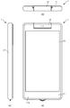
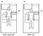
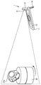
도 1은, 본 발명의 정보 처리 단말의 일 실시 형태의 외관 구성을 도시하는 도면이다. 도 1(a)은, 정보 처리 단말의 정면도이다. 도 1(b)은, 정보 처리 단말(1)의 상면도이다. 도 1(c)은, 정보 처리 단말의 좌측면도이다. 정보 처리 단말(1)은, 적어도 표시 기능과 디지털 카메라 기능을 구비하고, 본체부(11)와 연결부(12)로 구성되고, 이것들은 회동 가능하도록 서로 접속되어 있다.1 is a diagram showing an external configuration of an embodiment of an information processing terminal of the present invention. 1 (a) is a front view of an information processing terminal. Fig. 1 (b) is a top view of the
본체부(11)는, 평면 형상 사각형의 단주(短柱) 형상으로 형성되어, 각종 기판 등이 내장되는 제1 하우징이다. 본체부(11)의 소정의 일면(11a)(이하, 「정면(11a)」이라고 부름)에는, 터치 패널식 디스플레이 등으로 구성되는 표시부(13)가 배치된다.The
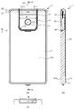
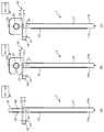
도 2는, 도 1의 정보 처리 단말의 외관 구성을 도시하는 도면이다. 도 2(a)는, 정보 처리 단말의 배면도이다. 도 2(b)는, 도 2(a)의 선 A-A에 있어서의 단면도이다. 도 2(c)는, 도 2(a)를 상면에서 본 단면도이다.Fig. 2 is a diagram showing an external configuration of the information processing terminal of Fig. 1. Fig. 2 (a) is a rear view of the information processing terminal. Fig. 2 (b) is a cross-sectional view taken along the line A-A in Fig. 2 (a). Fig. 2 (c) is a sectional view of Fig. 2 (a) taken from the top.
본체부(11)의 배면(11b)은, 도 1에서 상술한 정면(11a)에 대향하는 측의 일면이다. 연결부(12)는, 평면 형상 대략 직사각형으로 형성되어, 본체부(11)의 배면(11b)의 일방의 단변측에 회동 가능하도록 배치된다. 연결부(12)는, 카메라 기부(基部)(12-1)와, 카메라 지향부(12-2)를 가지고 있다. 카메라 지향부(12-2)의 정면(도 2(a)에서 보여지고 있는 측의 면)에는 원 형상의 카메라(21)가 배치되어 있다. 즉, 연결부(12)는, 카메라(21)를 내장하는 제2 하우징이다. 카메라(21)는, 피사체를 촬상하는 촬상부이다. 카메라(21)에 의해 촬상된 피사체를 포함하는 촬상 화상은, 표시부(13)에 표시된다. 여기서, 도 2(c)에 도시한 바와 같이, 함몰 폭(W)은, 카메라부용의 함몰의 폭이다. 그리고, 회전 반경(r2)은, 2 축째의 힌지의 회전축(중심)으로부터 가장 긴 회전 반경이다. 이에 의하여, 함몰 폭(W)과 회전 반경(r2)의 관계는, 이하의 식 (1)에서 나타내는 관계가 된다.The
W/2>r2 ... (1)W / 2 > r2 (1)
카메라 기부(12-1)는, 회동축(Z1)을 회동 중심으로 하여 본체부(11)에 대하여 연결부(12) 전체를 회동 가능하도록 축지(軸支)된다. 보다 구체적으로는, 카메라 기부(12-1)는, 주형(柱形)의 외형 중, 단면을 본체부(11)에 접힘 접촉(摺接)하면서, 회동축(Z1)을 중심으로 하여 회동할 수 있도록 구성된다.The camera base 12-1 is pivotally supported so that the entire connecting
축지(軸支)는 양단면 사이를 관통하고 하는 것이 강도 상 바람직하지만, 양단면으로부터 상호 회동축을 삽입하여 양팔보 축지해도 되고, 나아가서는 외팔보 축지해도 된다. 카메라(21)가 탑재되는 카메라 지향부(12-2)는, 회동축(Z1)에 대하여 대략 직교 방향으로 배치된 회동축(Z3)을 회동 중심으로 하여 카메라 기부(12-1)에 대하여 회동 가능하도록 외팔보 축지된다.It is preferable for the shaft to penetrate between both end faces in terms of strength, but it is also possible to insert the mutual pivot shafts from both end faces to shave both arms, and furthermore, to cantilever the pivot shaft. The camera directing part 12-2 on which the
여기서, 카메라(21)의 배치 방향은, 회동축(Z3)에 대해서도, 대략 90 도이다. 즉, 카메라(21)는, 회동축(Z1)과 회동축(Z3)이라고 하는 2 개의 대략 직교 독립한 회동축에 의해, 본체부(11)에 대하여 입체각 상에서 모션을 취할 수 있다.Here, the arrangement direction of the
이와 같이, 카메라(21)의 광축 방향과 표시부(13)의 법선 방향이 이루는 각도를 변화시키는 회동축(Z1)과, 회동축(Z1)과는 다른 방향(본 예에서는 대략 직교 방향)의 회동축(Z3)을 포함하는 복수의 회동축에 의하여, 카메라(21)를 본체부(11)에 대하여 상대적으로 회동 가능하도록, 직접적 또는 간접적으로 연결하는 부가 연결부(12)이다. 연결부(12)는, 본체부(11)보다 용적이 작은 가동부를 하나 이상 가지고 있다. 본 예에서는, 이러한 가동부로서, 카메라 기부(12-1)와, 카메라 지향부(12-2)가 설치되어 있다. 촬상부인 카메라(21)는, 하나 이상의 가동부 중, 소정의 하나의 소정의 면에 배치되면 충분하지만, 본 예에서는 상술한 바와 같이, 카메라 지향부(12-2)의 정면에 배치되어 있다. 그리고, 회동축(Z1)의 방향과 회동축(Z3)의 방향이 이루는 각도는 대략 90 도이다.As described above, the rotation axis Z1, which changes the angle formed by the optical axis direction of the
정보 처리 단말(1)에는, 또한, 해당 정보 처리 단말(1)을 책상 등의 위에 기대어 세워놓아 배치시킬 수 있도록, 스탠드(14)가 설치되어 있다. 스탠드(14)는, 회동축(Z2)을 회동 중심으로 하여 본체부(11)에 대하여 회동 가능하도록 축지된다. 즉, 스탠드(14)는, 프레임 형상으로 형성되고, 회동축(Z2)을 중심으로 하는 회동에 의해 본체부(11)와 바람직한 임의의 각도를 이룸으로써, 수평면 상에서 정보 처리 단말(1)을 자립 안정시킨다(후술하는 도 5 참조). 또한, 도시한 평면 형상 대략 コ 자 형상은 일예이며, 평면 형상 대략 U 자 형상 등이여도 좋음은 말할 필요도 없다. 나아가서는 후술하는 수직면 상에서의 사용이 가능하다면, 평면 형상 훅 형상 등이여도 된다.The
스탠드(14)는, 연결부(12)를 프레임 형상으로 둘러싸는 형상으로 함으로써, 스탠드(14)와 연결부(12)를 별도로 떨어진 위치에 배치하는 것보다도 대폭 스페이스 효율을 올릴 수 있어, 쓸모없이 정보 처리 단말(1)의 하우징을 크게 하지 않게 할 수 있다. 또는, 내부 기판을 쓸모없이 분할하지 않도록 할 수 있다. 또한, 연결부(12)와 스탠드(14)는, 회동축에 대한 양단면에 대한 중심선을, 선 A-A와 같이 대략 공유하고 있다.The
또한, 이하, 회동축(Z1 내지 Z3)에 대하여 설명한다. 회동축(Z1)은, 본체부(11)와 연결부(12)를 접속축의 회동 중심이다. 회동축(Z1)의 회동 범위는, 배면(11b)으로부터 대략 180 도 이상까지이며, 270 도를 넘는 것이 바람직하다.Hereinafter, the pivot shafts Z1 to Z3 will be described. The pivot axis Z1 is the center of rotation of the connecting shaft between the
회동축(Z2)은, 본체부(11)와 스탠드(14)와의 접속축의 회동 중심이다. 회동축(Z2)의 회동 범위는, 배면(11b)으로부터 180 도까지 달하는 것이 바람직하고, 특히 배면(11b)으로부터 90 도까지의 임의의 각도를, 수평면 상에서의 정보 처리 단말(1)의 자중(自重) 모멘트에 대항하여 유지할 수 있도록, 적절한 회동 저항이 주어져 있다. 이에 의해 유저는, 정보 처리 단말(1)을, 수평면 상에서 원하는 각도 자세로 자립 안정시켜 배치할 수 있다. 또한, 스탠드(14)의 회동축(Z2)측에 오프셋시키는 부위를 설치하여, 회동축(Z1)과 회동축(Z2)의 회동 중심을 공유시켜도 된다.The pivot axis Z2 is the center of rotation of the connecting shaft between the
회동축(Z3)은, 카메라 기부(12-1)와, 카메라 지향부(12-2)와의 접속축의 회동 중심이다. 회동축(Z3)은, 회동축(Z1)과는 대략 직교하여 설치되고, 회동축(Z1) 둘레의 대략 직교 평면 상을 회동한다. 회동축(Z3)의 회동 범위는, 회동축(Z3)이 회동하는 회동축(Z1) 둘레의 대략 직교 평면으로부터 좌우 180 도씩까지 달하는 것이 바람직하다.The rotation axis Z3 is a rotation center of the connection axis between the camera base 12-1 and the camera directing unit 12-2. The rotation axis Z3 is provided substantially perpendicular to the rotation axis Z1 and rotates on a substantially orthogonal plane around the rotation axis Z1. It is preferable that the rotation range of the rotation shaft Z3 extends from the substantially orthogonal plane around the rotation axis Z1 on which the rotation axis Z3 rotates to 180 degrees on both sides.
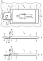
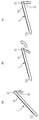
도 3은, 도 1의 정보 처리 단말의 연결부를 회동시킨 모습을 도시하는 도면이다. 도 3(a)에서는, 도 1의 정보 처리 단말(1)의 연결부(12)(보다 정확하게는 카메라 기부(12-1))는, 회동축(Z1)을 중심으로 90 도 회동한 상태로 되어 있다. 도 3(b)에서는, 연결부(12)(보다 정확하게는 카메라 기부(12-1))는, 도 3(a)의 상태로부터 더욱 회동축(Z1)을 중심으로 회동하여, 회동축(Z1)을 중심으로 180 도 회동한 상태로 되어 있다. 도 3(c)에서는, 연결부(12)(보다 정확하게는 카메라 지향부(12-2))는, 도 3(b)의 상태로부터 더욱 회동축(Z3)을 중심으로 90 도 회동한 상태로 되어 있다. 도 3(a) 내지 도 3(c)에 도시한 바와 같이, 거리 h1는, 1 축째의 힌지의 회전축(중심)으로부터, 정보 처리 단말(1)(스마트폰)의 본체부(11)의 상측면, 정보 처리 단말(1)의 윗면(표시부(13)가 있는 쪽), 또는 정보 처리 단말(1)의 저면(표시부(13)가 없는 쪽)까지의 가장 긴 거리이다. 또한, 거리 h2는, 1 축째의 힌지의 회전축(중심)으로부터 2 축째의 힌지의 회전 단면까지의 거리이다. 그리고, 거리 h1와 거리 h2의 관계는, 이하의 식 (2)에서 나타내는 관계가 된다.Fig. 3 is a diagram showing a state in which the connection portion of the information processing terminal of Fig. 1 is rotated. 3 (a), the connection portion 12 (more precisely, the camera base 12-1) of the
h2>h1...(2)h2 > h1 (2)
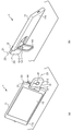
도 4는, 도 1의 정보 처리 단말(1)의 스탠드(14)를 회동시킨 모습을 도시한 도면이다. 도 4(a)는, 상술의 도 3(b)과 동일한 상태이며, 스탠드(14)는 회동하고 있지 않고, 본체부(11)에 수납되어 있다. 도 4(b)에서는, 스탠드(14)는, 도 4(a)의 상태로부터 더욱 회동축(Z2)을 중심으로 회동하고, 회동축(Z2)을 중심으로 180 도 회동한 상태로 되어 있다. 또한, 도 3과 마찬가지로, 거리 h1와 거리 h2의 관계는, 상기의 식 (2)와 같은 관계이다.Fig. 4 is a view showing a state in which the
도 4(b)에 도시한 바와 같이, 스탠드(14)를 회동축(Z2)을 중심으로 180 도 회동한 상태로 함으로써, 유저는, 도 4(c)에 도시한 바와 같이, 스탠드(14)를 벽(KB)의 클립(CL) 등에 걺으로써, 정보 처리 단말(1)을 벽(KB)에 달 수 있다. 이 도 4(c)의 상태에서는, 카메라(21)의 광축 방향(피사체의 촬영 방향) 및 표시부(13)의 법선 방향(유저가 표시부(13)를 보는 방향)은, 벽(KB)의 표면에 대한 법선 방향으로 되어 있다. 따라서, 유저는, 벽(KB)에 대향하여 위치함으로써, 카메라 시점 화상(자신이 비치는 화상)을 보면서, 자신을 피사체로 한 촬영, 즉, 셀프 샷(본인 촬영)을 하는 것이 용이하게 가능하다.4 (b), when the
이상 설명한 바와 같이, 회동축(Z2)에 의해 스탠드(14)는 본체부(11)에 대하여 회동하여, 회동축(Z1) 및 회동축(Z3)의 2 축에 의해 카메라(21)(연결부(12))는 표시부(13)(본체부(11))에 대하여 회동한다. 이 때문에, 유저는, 셀프 샷(본인 촬영) 등을 할 때에, 도 4에 도시한 바와 같이, 정보 처리 단말(1)을 벽(KB)에 걸어 사용할 수도 있고, 도 5에 도시한 바와 같이, 정보 처리 단말(1)을 탁상에 기대어 세워놓고 사용할 수도 있다.As described above, the
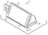
도 5는, 도 1의 정보 처리 단말(1)을 탁상에 기대어 세워놓고 사용하고 있는 모습을 도시하는 도면이다. 도 5(a)는, 표시부(13)가 배치된 정면(11a)측을 보는 시점에 의한 사시도이다. 도 5(b)는, 표시부(13)가 배치된 배면(11b)측을 보는 도 1의 정보 처리 단말의 탁상에서의 사용 형태를 나타내는 사시도이다. 본 형태에 있어서의 스탠드(14)는, 도 4(a)의 상태에서부터 회동축(Z2)을 중심으로 90 도 이내에서 회동한 상태로 되어 있다.Fig. 5 is a diagram showing a state in which the
회동축(Z2)에는, 배면(11b)으로부터 90 도까지의 임의의 각도를, 수평면 상에서의 정보 처리 단말(1)의 자중(自重) 모멘트에 대항하여 유지할 수 있도록, 적절한 회동 저항이 주어져 있다. 이에 의해 유저는, 정보 처리 단말(1)을, 수평면 상에서 원하는 각도 자세로 자립 안정시켜 배치할 수 있다.A proper turning resistance is given to the pivot axis Z2 so that an arbitrary angle from the
도 1의 정보 처리 단말(1)에 따른 유저는, 본인을 촬상하는 경우 등에는, 도 5에 도시한 바와 같이, 본체부(11)와 스탠드(14)가 소정 각도 확개(開)하도록 변형한 상태의 정보 처리 단말(1)을 탁상 등에 입설(立設)시킨다. 이 상태에서도, 정보 처리 단말(1)은, 회동축(Z1) 및 회동축(Z3)을 회동시킴으로써, 카메라(21)를 피사체로 향할 수 있다.The user according to the
또한, 정보 처리 단말(1)은, 셔터 리모콘 기능 또는 셀프타이머 기능을 병용함으로써, 본체부(11)를 손으로 쥐지 않아도 촬영할 수 있으므로, 후술하는 모든 과제를 해결할 수 있다.Further, the
이상 설명한 본 발명이 적용되는 정보 처리 단말(1)을 채용함으로써, 다음과 같은 다양한 효과를 갖는 것이 가능하다.By employing the
즉, 종래의 스마트폰에서의 프론트 카메라를 이용한 셀프 샷(본인 촬영)이 전세계적으로, 특히 아시아권에서 유행하고 있다. 그러나, 종래의 스마트폰에서는, 아래와 같은 다양한 과제가 있었다. 본 발명이 적용되는 정보 처리 단말(1)을 채용함으로써, 이들 다양한 과제를 해결할 수 있다고 하는 효과를 가질 수 있다.That is, a self-shot (self-photographing) using a front camera in a conventional smart phone is prevalent all over the world, especially in Asia. However, the conventional smartphone has various problems as described below. By adopting the
예를 들면, 종래의 스마트폰을 이용하는 유저는, 자신의 손으로 셔터를 누르므로, 본인 손의 길이 이상으로 떨어진 거리로부터 본인들의 사진을 찍을 수 없다. 즉, 광각의 한도가 있으므로, 함께 찍고자 하는 전원(가족, 애인, 동료 등)이 들어오지 않을 가능성이 있거나, 본인의 전신 사진을 찍는 것은 불가능하다. 이 과제의 종래의 해결 방법으로서는, 셀프 스틱(본인 촬영 봉)을 이용하는 방법이 있다. 이 방법으로는, 본인 손의 길이 이상으로 떨어진 거리로부터 사진을 찍을 수도 있으나, 셀프 스틱의 길이 이상으로 떨어진 거리로부터는 찍히지 않는다. 또한, 셀프 스틱을 가지고 다닐 필요성이 있고, 안전성의 관점에서 셀프 스틱의 사용을 금지하는 장소(테마파크나 스포츠 시설 또는 콘서트 회장이나 역의 홈 등)도 나오고 있어, 만능 해결 방법은 아니다. 즉, 셀프 스틱을 이용하지 않고 촬영하고자 하는 과제가 있다. 이 과제의 해결 방법은, 본 발명이 적용되는 정보 처리 단말(1)을 채용하는 것이다. 즉, 본 발명이 적용되는 정보 처리 단말(1)은, 스탠드(14)를 가지고 있으므로, 도 4 또는 도 5에 도시한 바와 같이, 벽이나 탁상에 고정 가능하고, 셀프 스틱이 불필요해진다.For example, a user using a conventional smart phone can not take a picture of himself / herself from a distance that is longer than the length of his or her hand because the user presses the shutter with his / her hand. In other words, there is a wide angle limit, and there is a possibility that the power (family, lover, co-worker) that you want to shoot together may not come in, or it is impossible to take a picture of yourself. As a conventional solution to this problem, there is a method using a self-stick (self-image pickup stick). With this method, you can take pictures from a distance that is more than your hand's length, but not from distances farther than your self-stick's length. In addition, there is a need to carry a self-stick, and a place (a theme park, a sports facility, a concert hall, a station home, etc.) where the use of the self-stick is prohibited from the viewpoint of safety comes out. That is, there is a problem to shoot without using the self-stick. The solution to this problem is to adopt the
또한, 본인의 손을 뻗으므로, 셔터를 누른 손이 뻗어진 상태에서만 촬영이 되어, 부자연스러운 포즈가 된다. 이는 셀프 스틱을 사용해도 약간 부자연스러움이 완화되는 경우도 있으나, 부자연스러움은 남고, 본인이 취하고자 하는 포즈(예를 들면, 양손을 사용한 포즈 등)를 할 수 없는 경우가 있다.In addition, since the user's hand is stretched, shooting is performed only when the hand holding the shutter is extended, resulting in an unnatural pose. This may alleviate some of the unnaturalness even though the self-stick is used, but the unnaturalness may remain and the user may not be able to perform a pose (for example, a pose using both hands) to be taken.
즉, 셀프 스틱을 이용하지 않고 촬영하고자 하는 과제가 있다. 이 과제의 해결 방법은, 본 발명이 적용되는 정보 처리 단말(1)을 채용하는 것이다. 즉, 본 발명이 적용되는 정보 처리 단말(1)은, 스탠드(14) 및 셀프타이머 및 셔터 리모콘 기능을 가지고 있으므로, 도 4 또는 도 5에 도시한 바와 같이, 벽이나 탁상에 고정 가능하고, 셀프 스틱이 불필요해진다.That is, there is a problem to shoot without using the self-stick. The solution to this problem is to adopt the
또한, 보다 많은 인원의 셀프가 되면, 셀프라고 하기보다는 집합 사진이 되지만, 자신의 손으로도, 셀프 스틱으로도, 전원이 카메라에 들어가지 않는 경우가 있다. 이러한 경우는, 동료 중 한사람이 희생하여 촬영자가 되지만, 촬영자는 집합 사진에 들어갈 수 없다. 점포에서 파티 등을 열 때에는, 점원에 의뢰하여 집합 사진의 촬영을 받는 경우가 많으나, 점원을 부를 필요가 있으므로 귀찮다.In addition, if the number of people becomes more than the number of people, it becomes a group picture rather than a self, but the power may not enter the camera by the hand or the self stick. In this case, one of the peers is sacrificed to become the photographer, but the photographer can not enter the collective photograph. When opening a party at a store, it is often the case that a clerk is asked to take a group photo, but it is troublesome to call a clerk.
즉, 촬영 대상자 이외의 사람의 손을 번거롭게 하지 않고, 촬영 대상자를 전원, 사진에 넣고자 하는 과제가 있다. 이 과제의 해결 방법은, 본 발명이 적용되는 정보 처리 단말(1)을 채용하는 것이다. 즉, 본 발명이 적용되는 정보 처리 단말(1)은, 스탠드(14) 및 카메라의 2 축 회동 기구를 가지고 있으므로, 도 4 또는 도 5에 도시한 바와 같이, 벽이나 탁상에 고정 가능하여, 촬영 대상자 이외의 사람의 손이 불필요해진다.That is, there is a problem that the person to be photographed is to be put into the power source and the photograph without making the hand of the person other than the person to be photographed unnecessary. The solution to this problem is to adopt the
또한, 예를 들면, 스포츠의 폼을 스스로 확인할 때에, 스마트폰의 카메라를 사용하여 촬영하고 싶으나, 스마트폰을 마루나 책상 위 등에 고정하는 것이 없으면 촬영조차 불가능하여, 스마트폰으로의 촬영을 단념하는 경우가 많다.In addition, for example, when a form of a sport is checked by itself, it is desired to shoot using a camera of a smartphone, but if the smartphone is not fixed on a floor, a desk, or the like, There are many cases.
마찬가지로, 책상 위 등에 스마트폰을 두어 셀프 샷을 찍는 경우도 있으나, 피사체에 프론트 카메라를 향하여 스마트폰을 둘 때에, 안정되게 둘 수 없거나, 접치(接置)에 시간이 걸린다.Likewise, when a smartphone is placed on a desk or the like to take a self-shot, there is a case in which the smartphone can not be stably placed or placed on the front camera toward the subject.
즉, 삼각대를 이용하지 않고 촬영하고자 하는 과제가 있다. 이 과제의 해결 방법은, 본 발명이 적용되는 정보 처리 단말(1)을 채용하는 것이다. 즉, 본 발명이 적용되는 정보 처리 단말(1)은, 스탠드(14) 및 카메라의 2 축 회동 기구를 가지고 있으므로, 도 4 또는 도 5에 도시한 바와 같이, 벽이나 탁상에 고정 가능하여, 삼각대가 불필요해진다. 또한, 세로로 긴 화면으로 촬영하고자 하는 경우에는, 도 9와 같이 스탠드(14)를 세워, 연결부(12)를 180 도 이상 회동시킴으로써, 탁상에 고정한 상태에서 촬영할 수 있으므로, 삼각대가 불필요해진다. 이 경우, 반드시 스탠드(14)를 세울 필요는 없다.That is, there is a problem to be photographed without using a tripod. The solution to this problem is to adopt the
또한, 스마트폰으로 비디오 채팅을 하면, 많은 사람이 스마트폰의 프론트 카메라에 자신의 얼굴을 비추기 위하여, 채팅 내내 쭉 스마트폰을 가지고 있을 필요가 있다.Also, when video chatting on a smartphone, many people need to have a smartphone all the time throughout the chat in order to shine their face on the smartphone's front camera.
조사에 의하면 80%의 사람이 손에 쥐고 채팅하고 있다고 대답하고 있어, 채팅하는 시간에 따르기도 하지만, 손이 지쳐버리고 만다.According to the survey, 80% of people say they are chatting in their hands, even following the time of chatting, but their hands are exhausted.
즉, 스마트폰을 손에 쥐지 않고 비디오 채팅을 하고자 하는 과제가 있다. 이 과제의 해결 방법은, 본 발명이 적용되는 정보 처리 단말(1)을 채용하는 것이다. 즉, 본 발명이 적용되는 정보 처리 단말(1)은, 스탠드(14) 및 카메라의 회동 기구를 가지고 있으므로, 도 4 또는 도 5에 도시한 바와 같이, 벽이나 탁상에 고정 가능하여, 스마트폰을 손에 쥐는 것이 불필요해진다. 또한, 세로로 긴 화면으로 자신의 얼굴을 촬영하여 비디오 채팅을 하고자 하는 경우에는, 도 9와 같이 스탠드(14)를 세워, 연결부(12)를 180 도 이상 회동시킴으로써, 탁상에 고정한 상태에서 촬영할 수 있으므로, 스마트폰을 손에 쥐는 것이 불필요해진다. 이 경우, 반드시 스탠드(14)를 세울 필요는 없다.That is, there is a problem of video chatting without holding a smartphone in hand. The solution to this problem is to adopt the
또한, 이들 과제의 해결책으로서, 스마트폰을 책상 위 등에 두기 위한, 스탠드를 스마트폰에 탑재하는 방법이 있으나, 스탠드에서 표시 화면과 프론트 카메라의 각도가 고정되어 버리므로, 반드시 피사체 방향으로 카메라가 향하지 않아, 사진 또는 영상을 찍는다고 하는 목적으로는, 이것들도 만능 해결책은 되지 않는다.As a solution to these problems, there is a method of mounting a stand on a smart phone to place a smart phone on a desk, but since the angle between the display screen and the front camera is fixed on the stand, For the purpose of taking pictures or video, these are not universal solutions either.
즉, 각도가 고정된 프론트 카메라를 이용하지 않고 촬영하고자 하는 과제가 있다. 이 과제의 해결 방법은, 본 발명이 적용되는 정보 처리 단말(1)을 채용하는 것이다. 즉, 본 발명이 적용되는 정보 처리 단말(1)은, 스탠드(14) 및 카메라의 2 축 회동 기구를 가지고 있으므로, 도 4 또는 도 5에 도시한 바와 같이, 리어 카메라를 2 축 회동에 의해 정면으로 돌아 들어가게 하여 자유로운 각도로 지향시키는 것이 가능하여, 각도가 고정된 프론트 카메라가 불필요해진다. 또한, 세로로 긴 화면으로 촬영하고자 하는 경우는, 도 9와 같이 스탠드(14)를 세워, 연결부(12)를 180 도 이상 회동시킴으로써, 탁상에 고정한 상태에서 촬영할 수 있으므로, 각도가 고정된 프론트 카메라가 불필요해진다. 이 경우, 반드시 스탠드(14)를 세울 필요는 없다.That is, there is a problem to be photographed without using a front camera whose angle is fixed. The solution to this problem is to adopt the
또한, 스마트폰이 만일 스탠드를 구비해도, 둘 장소가 없고, 벽 밖에 없으면, 스마트폰을 두는 것은 불가능하다. 이 과제의 해결책으로서, 벽에 정보 처리 단말을 매달아 고정하는 방법도 있으나, 그것을 위한 훅을 스마트폰에 준비할 필요가 있어서, 그것도 스마트폰 본체에 스페이스가 필요해진다.Also, if a smartphone has a stand, there are no two places, only a wall, it is impossible to place a smartphone. As a solution to this problem, there is a method of fixing the information processing terminal to the wall by fixing it to the wall. However, it is necessary to prepare a hook for the smartphone so that a space is required for the smart phone itself.
즉, 훅을 별도로 구비하지 않고자 하는 과제가 있다. 이 과제의 해결 방법은, 본 발명이 적용되는 정보 처리 단말(1)을 채용하는 것이다. 즉, 본 발명이 적용되는 정보 처리 단말(1)은, 연결부(12) 및 스탠드(14)를 180 도 회동시킨 상태로 함으로써, 스탠드(14)와 연결부(12)의 사이에 설치되어 있는 공극을 이용하여, 평면 상에 돌기부나 핀 형상 부재를 이용하여 현가(懸架) 지지시킬 수 있으므로, 벽걸이로의 사용에 바람직하며, 훅을 별도 구비할 필요가 없어진다.That is, there is a problem that the hook is not provided separately. The solution to this problem is to adopt the
또한, 프론트 카메라는 일반적으로, 리어 카메라와 비교하여,In addition, the front camera generally has, compared to the rear camera,
(가) 저해상도(end) Low resolution
(나) 저감도(어두운 장면에서는 플래시 없이는 촬영할 수 없다)(I) Low sensitivity (can not shoot without flash in dark scenes)
(다) 고정 초점으로, 오토 포커스는 아님(All) Fixed focus, not autofocus
(라) 오토 포커스의 것도 있으나, 오토 포커스의 스피드가 느림(la) Some autofocus are available, but the autofocus speed is slow
(마) 저줌 배율(hemp) Low zoom factor
(바) 플래시 라이트가 없음(bar) No flash light
과 같이, 성능적으로 뒤떨어지는 것이 많아, 깔끔한 화질로 촬상할 수 없다. 또한, 리어 카메라와 프론트 카메라는 성능이 다른 경우, 한 기종을 위하여, 2 개의 카메라를 개발할 필요가 있다. 이 과제의 해결 방법으로서, 리어 카메라로, 셀프 샷을 찍는 어플리케이션이 있으나, 표시부가 보이지 않으므로, 소리로 네비게이트하는 등, 사용감은 매우 안좋았다.There are many performance deteriorations, so that it is not possible to capture images with a clear image quality. In addition, if the performance of the rear camera and the front camera differ, it is necessary to develop two cameras for one model. As a solution to this problem, there is an application for taking a self shot with the rear camera, but since the display portion is not visible, the feeling of use is very bad, such as navigating through the sound.
즉, 표시부를 보지 않고 셀프 샷을 찍기 위한 어플리케이션 프로그램은, 사용하지 않고자 하는 과제가 있다. 이 과제의 해결 방법은, 본 발명이 적용되는 정보 처리 단말(1)을 채용하는 것이다. 즉, 본 발명이 적용되는 정보 처리 단말(1)은, 고성능 카메라로서의 카메라(21)를 단말 본체에 대하여 자유로운 방향을 향하는 것이 가능하고, 카메라 시점 화상을 시인하면서도, 자유로운 자세로 촬영할 수 있으므로, 표시부(13)를 보지 않고 셀프 샷을 찍기 위한 어플리케이션 소프트웨어가 불필요해진다.That is, there is a problem that an application program for shooting a self shot without looking at the display unit is not used. The solution to this problem is to adopt the
또한, 상기의 해결책인 스탠드와 회동식 카메라도, 본체측에 회동을 위한 각각의 축이 필요하게 되고, 그 두 개의 축용으로 스페이스를 확보할 필요가 있어, 본체의 하우징이 보다 커져 버린다. 또한, 카메라의 회동의 방법에도 따르지만, 스탠드로, 세운 스마트폰의 카메라가 회동해도, 피사체로 카메라가 향하지 않는 경우가 많아, 해결책이 되지 않는 경우가 많다. 피사체에 카메라가 향하도록 더욱 회동축을 늘리는 것도 가능하지만, 사진을 촬영할 때에 피사체로 항상 카메라를 향하고나서 촬영하는 것은 귀찮은 경우가 많다.In addition, both the stand and the pivoting camera, which are the solution to the above problems, require each shaft for pivoting on the body side, and it is necessary to secure space for the two shafts, and the housing of the body becomes larger. In addition, although the camera of the smart phone rotated by the stand is rotated by the stand, there are many cases where the camera does not face the subject, which is often the solution, although it depends on the method of rotating the camera. Although it is possible to further extend the pivot axis so that the camera faces the subject, it is often troublesome to shoot the subject after the camera is always pointed at the time of photographing.
즉, 적은 회동축 수로 피사체로 항상 카메라를 향하고자 하는 과제가 있다. 이 과제의 해결 방법은, 본 발명이 적용되는 정보 처리 단말(1)을 채용하는 것이다. 즉, 본 발명이 적용되는 정보 처리 단말(1)은, 스탠드(14)와 카메라(21)의 회동축을 겸용시켜도 되므로, 도 4 또는 도 5에 도시한 바와 같이, 2 축 회동만으로 피사체로 항상 카메라(21)를 향하는 것이 가능하여, 회동축을 늘리는 것이 불필요해진다.That is, there is a problem that the camera always faces the subject with a small number of rotation axes. The solution to this problem is to adopt the
또한, 종래의, 리어 카메라 및 정면 표시부도 본체에 고정된 정보 처리 단말에서는, 눈보다 높은 위치로부터 촬영하는 하이 앵글 샷이나, 허리보다 낮은 위치로부터 촬영하는 로우 앵글 샷은, 카메라의 방향과 표시부의 방향이 대향하고 있으므로, 표시부를 보면서 촬영하는 것은 곤란하다. 예를 들면, 하이 앵글 샷은, 사진을 찍을 때에, 피사체가 사람들에 의해 둥글게 둘러싸이거나 할 때에, 사람들이 둘러싸는 곳의 위로부터 촬영하는 것과 같은 때에 필요해지지만, 카메라를 피사체로 향하면 표시부가 위를 향하게 되어버리므로, 카메라 시점 화상을 시인하면서 촬영할 수 없다.In the conventional information processing terminal fixed to the main body of the rear camera and the front display unit, a high-angle shot taken from a position higher than the eye or a low-angle shot taken from a position lower than the waist, It is difficult to take a picture while viewing the display portion. For example, a high-angle shot is required when photographing, when the subject is rounded by people, or when photographing from above people's surroundings. However, when the camera is aimed at a subject, The user can not shoot while viewing the camera viewpoint image.
마찬가지로, 허리보다 낮은 위치로부터 카메라보다 높은 위치에 있는 피사체로 카메라를 향하면, 표시부가 아래를 향하게 되어버리므로, 역시나 카메라 시점 화상을 시인하면서 촬영할 수 없다. 이 과제의 해결책으로서, 카메라가 회동하면, 카메라의 방향과 표시부의 방향을 따로 따로 설정할 수 있으므로, 카메라 시점 화상을 시인하면서 촬영하는 것이 가능해진다.Likewise, when the subject is positioned at a position higher than the waist and the subject is positioned higher than the waist, the display portion faces downward, so that the subject can not photograph while viewing the camera viewpoint image. As a solution to this problem, when the camera rotates, the direction of the camera and the direction of the display portion can be set separately, so that it is possible to shoot while viewing the camera viewpoint image.
이 때에, 카메라를 회전시켜 가면, 화면의 상하 방향이 바뀔 때가 있으나, 별 생각을 기울이지 않으면 상하 방향이 반대가 되어 버리는 경우 등도 있다. 이러한 하이 앵글 샷이나 로우 앵글 샷 시에는, 카메라가 회전하는 방향이 정해져 있으면(정위치로부터 시계 방향으로 밖에 회전하지 않거나) 촬영하기 어려우므로, 양방향으로 회동 가능하다고 하는 것이 바람직하다.At this time, if the camera is rotated, the up and down direction of the screen may be changed, but the up and down direction may be reversed if not thought out. In such a high-angle shot or low-angle shot, it is preferable that the camera can be rotated bidirectionally since it is difficult to photograph the camera when the direction of rotation of the camera is fixed (it does not rotate only in the clockwise direction from the fixed position).
즉, 각도가 고정된 리어 카메라를 이용하지 않고 촬영하고자 하는 과제가 있다. 이 과제의 해결 방법은, 본 발명이 적용되는 정보 처리 단말(1)을 채용하는 것이다. 즉, 본 발명이 적용되는 정보 처리 단말(1)은, 스탠드(14) 및 카메라(21)의 2 축 회동 기구를 가지고 있으므로, 도 4 또는 도 5에 도시한 바와 같이, 리어의 카메라(21)를 2 축 회동에 의해 상하로 자유로운 각도로 지향시키는 것이 가능하여, 각도가 고정된 리어 카메라가 불필요해진다. 카메라(21)를 회동시키고 있으면, 어딘가의 타이밍에서, 촬영할 수 있는 화각(광각, 통상, 협각 등)을 자동으로 전환할 수 있으면 바람직하다. 일반적으로는 프론트 카메라의 광축 방향측은, 피사체까지의 거리가 짧은 경우가 많으므로, 광각으로 촬영하기를 원하나, 리어 카메라의 광축 방향측은, 통상 또는 협각으로 촬영하길 원한다. 따라서, 카메라의 방향에 의하여, 화각이 자동으로 바뀌면 바람직하다.That is, there is a problem to shoot without using a rear camera whose angle is fixed. The solution to this problem is to adopt the
또한, 셀프 샷을 찍을 때에, 셔터 버튼이나 터치 패널을 눌러, 셔터를 내릴 필요가 있어서, 제대로 스마트폰을 홀드하지 못하고, 불안정하게 된 스마트폰을 떨어뜨리게 되어버리는 경우도 있다. 이 과제의 해결책으로서, 타이머 설정, 제스쳐 인식, 또는 음성 인식에 의한 셔터 압하가 있으나, 셔터가 내려지는 타이밍을 알기 어렵거나 반응이 나빠서, 예를 들면, 5 명이 점프한 순간을 찍고자 했을 때에는 사용하기 어렵다.In addition, when taking a self shot, it is necessary to lower the shutter by pressing the shutter button or the touch panel, so that the smartphone can not be properly held and the smartphone which has become unstable may be dropped. As a solution to this problem, there is a problem in that when the timer is set, the gesture recognition is performed, or the shutter is pressed down due to speech recognition, but it is difficult to know the timing at which the shutter is lowered or the reaction is bad. For example, it's difficult.
즉, 스마트폰으로부터 손을 놓고 셔터 버튼을 눌러 촬영하고자 하는 과제가 있다. 이 과제의 해결 방법은, 본 발명이 적용되는 정보 처리 단말(1)을 채용하는 것이다. 즉, 본 발명이 적용되는 정보 처리 단말(1)은, 셔터 리모콘 대응 기능을 가지고 있으므로, 도 4 또는 도 5에 도시한 바와 같이, 셀프 샷을 찍을 때에, 셔터 버튼이나 터치 패널을 누르지 않고 셔터를 내리는 것이 가능하여, 제대로 스마트폰을 홀드하는 것이 불필요해진다.In other words, there is a problem to shoot by pressing the shutter button while leaving the hand from the smartphone. The solution to this problem is to adopt the
여기서, 셔터 리모콘 대응 기능이 있어도, 예를 들면, 10 명이 그룹 샷을 촬영할 때에, 상술의 정보 처리 단말(1)을 책상 위 등에 설치하고, 10 명을 향해 카메라(21)를 회전시켜, 정보 처리 단말(1)로부터 멀리 떨어지면, 표시부(13)가 작아 안보이게 되어버려서, 카메라 시점 화상의 프레임에 전원이 들어가 있는지 모르거나 또는 각각의 표정을 알 수 없는 등의 이유로 인해, 셔터를 누르기 어려운 경우가 있다. 즉, 카메라 시점 화상을 어떠한 방법으로 확인하면서 촬영하고자 하는 과제가 있다. 이 과제의 해결 방법은, 다음과 같은 수법을 채용하는 것이다. 즉, 본 발명이 적용되는 정보 처리 단말(1)에 대하여, 카메라 시점 화상을 별도의 스마트폰이나 퍼스널 컴퓨터 등의 정보 처리 단말에, 유선 혹은 무선으로 전송하여, 조작도 가능하게 하는 화면 공유 기능을 탑재한다고 하는 수법을 채용하면 된다. 이에 의하여, 정보 처리 단말(1)의 카메라 시점 화상을 다른 정보 처리 단말과 공유하면서, 멀어진 위치로부터 정지 영상 또는 동영상의 촬영을 하는 것이 가능해진다. 정보 처리 단말끼리가 직접 연결되는 경우도 있다고 한다면, 인터넷 회선을 사용하여, 자택에 둔 정보 처리 단말(1)의 카메라 시점 화상을 오피스의 퍼스널 컴퓨터와 화면 공유하여, 그 퍼스널 컴퓨터의 화면을 보면서, 자택에 남아 있는 애완 동물의 촬영을 하는 것도 가능하다.For example, when 10 persons take a group shot, the
또한, 종래의 디지털 카메라나 스마트폰으로도, 카메라를 가로 이동시킴으로써, 합성의 파노라마 샷을 찍을 수 있다. 그러나, 스마트폰이나 카메라를 다양한 방향을 향하여 가로 이동하면서 촬영할 필요가 있으므로, 깔끔하게 합성할 수 없는 경우가 많다.In addition, even with a conventional digital camera or a smart phone, a synthetic panoramic shot can be taken by horizontally moving the camera. However, since it is necessary to photograph a smartphone or a camera while moving in various directions, it is often impossible to synthesize neatly.
즉, 본체를 가로 이동시키지 않고 카메라로 주위를 촬영하고자 하는 과제가 있다. 이 과제의 해결 방법은, 본 발명이 적용되는 정보 처리 단말(1)을 채용하는 것이다. 즉, 본 발명이 적용되는 정보 처리 단말(1)은, 카메라(21)의 회동축(Z1 및 Z3)에 대한 회동은 전동이면 되므로, 도 3에 도시한 바와 같이, 본체를 멈춘 채로 카메라(21)를 팬(pan)하는 것이 가능하여, 카메라(21)를 가로 이동시키는 것이 불필요해진다.That is, there is a problem that the user is required to photograph the surroundings with the camera without moving the main body horizontally. The solution to this problem is to adopt the
또한, 종래부터, 인간의 제스쳐를 기기나 게임의 조작에 활용하고자 하는 시도가 있으나, 제스쳐를 인식하는 카메라는 항상 피사체를 향하고 있을 필요가 있으므로, 카메라 단말과 게임 단말과는 별도로 준비할 필요가 있어, 스마트폰 한 대로 처리하는 것이 불가능하였다. 한편, 제스쳐 인식용의 카메라는 매우 고가이며, 추가의 비용이 발생하고 있었다.Conventionally, there is an attempt to utilize a human gesture in the operation of a device or a game, but since a camera that recognizes a gesture must always face a subject, it is necessary to prepare it separately from a camera terminal and a game terminal , It was impossible to process one smartphone. On the other hand, cameras for gesture recognition are very expensive and additional costs have been incurred.
즉, 제스쳐 인식 전용의 카메라를 사용하지 않고 제스쳐 인식하고자 하는 과제가 있다. 이 과제의 해결 방법은, 본 발명이 적용되는 정보 처리 단말(1)을 채용하는 것이다. 즉, 본 발명이 적용되는 정보 처리 단말(1)은, 사람에게 향하는 카메라(21)가 고기능(예를 들면, Exvision의 제스쳐 인식)이면 가능하며, 제스쳐 인식 전용의 카메라가 불필요해진다.That is, there is a problem to recognize a gesture without using a camera dedicated to gesture recognition. The solution to this problem is to adopt the
또한, 종래부터, 스마트폰에는, 보행자용의 네비게이션 소프트가 있으나, 그럼에도 특히 옥외라면, 자신이 향해 있는 방향을 간단히 모르고, 자신이 나아가야 하는 방향을 모르거나, 아는데까지 시간이 걸린다. 이 과제의 해결책으로서, 카메라를 사용한 AR에 의한 네비게이션이 있다.Conventionally, smart phones have navigation software for pedestrians, but even if they are outdoors, they do not know the direction to which they are heading and do not know the direction in which they should go, or take time to know. As a solution to this problem, there is AR navigation using a camera.
해당 네비게이션은, 실제로 카메라에 찍혀 있는 영상에 화살표를 중첩시키거나 하는 유저 인터페이스에 의하여, 방향를 인식하는 데에 시간이 걸리는 일도 없어, 금방 사용할 수 있게 된다. 단, 본체부 배면에 직교하는 각도로 고정된 카메라로 촬영하기 위해서는, 항상 스마트폰 본체부를 지면과 수직으로 가질 필요가 있고, 그 때의 표시부는 매우 보기 어려운 각도가 되거나, 계속 쥐기가 피곤하게 된다.The navigation can be used immediately because the navigation does not take time to recognize the direction by the user interface that superimposes the arrow on the image actually shot on the camera. However, in order to shoot with a camera fixed at an angle orthogonal to the back surface of the main body portion, it is necessary to always keep the main body portion of the smartphone perpendicular to the ground, and the display portion at that time becomes an angle that is very difficult to see, .
옥외에서의 보행 중에 스마트폰을 사용하는 행위인 「보행중 스마트폰」도 사회 현상으로 되어 있으나, 화면에 집중하고 있으므로, 부딪히게 될 때까지 좀처럼 깨닫지 못한다. 이들 두 개의 과제도, 회동식의 카메라가 있으면 해결할 수 있는 경우가 있다. 「보행중 스마트폰」 시에, 회동한 카메라(21)의 영상을 표시부(13)에 윈도우의 하나로서 표시하거나, 장애물의 존재를, 소리, 화면, 또는 진동으로 전달하는 것도 가능해지므로, 위험을 회피할 수 있다."Walking smartphone", which is the act of using smartphone while walking outdoors, is also a social phenomenon, but because it focuses on the screen, it hardly realizes until it is encountered. Both of these tasks can be solved with a rotating camera. It is possible to display the image of the
본 형태에서는, 표시면에 대하여 카메라가 세로 방향으로 회동하므로, 상기 두 개의 분류로 될 수 있으나, 카메라의 방향이 순조롭게 회동하는 경우는, 카메라가 유 동(遊動)하여 안정되지 않는다고 하는 문제도 있다.In this embodiment, since the camera rotates in the longitudinal direction with respect to the display surface, it can be divided into the above two types. However, when the direction of the camera rotates smoothly, There is a problem that it is not stabilized by floating.
즉, 본체를 파지하여 안정시켜도, 카메라가 유동하여 안정되지 않는다고 하는 과제가 있다. 이 과제의 해결 방법은, 본 발명이 적용되는 정보 처리 단말(1)을 채용하는 것이다. 즉, 본 발명이 적용되는 정보 처리 단말(1)은, 카메라(21)의 회동을 특정 각도로 잠글 수 있어서 좋고, 본체부(11)를 파지하여 안정시키면 카메라(21)도 안정된다.That is, even if the main body is gripped and stabilized, there is a problem that the camera does not flow and is not stabilized. The solution to this problem is to adopt the
또한, 최근, 만일의 사고 시, 영상 데이터 또는 GPS(Global Positioning System)에 의한 데이터 등을 기록함으로써, 사고의 객관적인 검증에 기여하는 것을 목적으로 하는, 자동차 또는 자전거에 탑재하는 드라이브 레코더가 급속히 확산되고 있다. 스마트폰에 어플리케이션 소프트웨어를 인스톨함으로써, 드라이브 레코더 대신으로 하는 것도 가능하지만, 그다지 확산되어 있지 않다. 자동차의 경우의 이유로서, 차의 대쉬보드 상에 흡반(吸盤) 또는 양면 테이프 등으로 스마트폰 등을 고정하는 홀더를 사용하여, 드라이버로부터 표시부를 보기 쉽도록 스마트폰을 고정하면, 그 스마트폰의 카메라의 광축 방향은, 촬영하고자 하는 차 전방 또는 후방을 향하지 않고, 대쉬보드가 찍혀 버린다. 즉, 드라이버로부터 보기 쉬운 위치 및 운전의 방해가 되지 않는 위치에 스마트폰을 두면, 드라이브 레코더의 역할을 완수할 수 없다. 한편, 드라이브 레코더로서의 영상을 우선하면, 스마트폰을 드라이버로부터 보기 어려운 위치에 설치해야 한다. 그렇게 함으로써, 스마트폰을 드라이브 레코더 겸 네비게이션 시스템으로서 이용하고자 하는 등의 겸용 용도를 만족시킬 수 없게 되어버린다. 자전거의 경우도 마찬가지이다. 그 때문에, 스마트폰을 드라이브 레코더로서 사용하는 것이 그다지 확대되어 있지 않다고 생각된다. 즉, 스마트폰을 드라이브 레코더로서 이용하면서, 다른 용도에도 동시에 사용하고자 하는 과제가 있다. 이 과제의 해결 방법은, 본 발명이 적용되는 정보 처리 단말(1)을 채용하는 것이다. 즉, 본 발명이 적용되는 정보 처리 단말(1)은, 카메라(21)를 단말 본체에 대하여 자유로운 방향으로 향하는 것이 가능하고, 네비게이션의 지도를 표시하면서, 화면의 일부에 카메라 시점 화상을 Picture in Picture와 같은 형태로 표시할 수 있으므로, 스마트폰을 드라이브 레코더로서 이용하면서, 다른 용도에도 동시에 사용할 수 있다. 따라서, 전용의 드라이브 레코더가 불필요해진다. 또한, 자동차로의 설치는, 가로로 긴 화면이 되도록 설치하지만, 자전거로의 설치는, 세로로 긴 화면이 되도록 설치하는 등, 카메라(21)가 2 축으로 회전할 수 있으므로, 폭넓은 설치의 방법에 대응할 수 있다.In recent years, a drive recorder mounted on an automobile or a bicycle has been rapidly spreading for the purpose of contributing to the objective verification of an accident by recording video data or data by GPS (Global Positioning System) in case of an accident have. It is also possible to replace the drive recorder by installing the application software on a smart phone, but it is not so spread. As a reason for the case of a car, if a smartphone is fixed on a dashboard of a car so that a display unit can be easily viewed from a driver by using a holder that fixes a smartphone or the like with a sucker or double-sided tape or the like, The direction of the optical axis of the camera is not directed toward the front or back of the car to be photographed, and the dashboard is photographed. That is, if the smartphone is placed in a position where it is easy to see from the driver and in a position where it does not disturb the driving, the role of the drive recorder can not be accomplished. On the other hand, if the image as the drive recorder is given priority, the smartphone should be installed in a position difficult to see from the driver. By doing so, it becomes impossible to satisfy the dual purpose of using the smart phone as a drive recorder and a navigation system. The same applies to bicycles. Therefore, it is considered that the use of a smart phone as a drive recorder is not so widened. That is, there is a problem that a smartphone is used as a drive recorder and simultaneously used for other purposes. The solution to this problem is to adopt the
또한, 향후, 스마트폰 업계에서는, 리어 카메라에 센서를 복수 개 탑재하여, 사진 촬영뿐만이 아니라, 거리를 측정하거나, 줌에 활용하거나 하는 예가 많아지고 있다고 보여지고 있다. 하지만, 프론트 카메라측도 동일한 대응을 하면, 비용이 배가 들게 되어버리므로, 보류될 가능성이 높고, 프론트와 리어에서 카메라의 기능차가 나게 되어버린다.In addition, in the smartphone industry in the future, it is considered that there are many cases in which a plurality of sensors are mounted on the rear camera and not only photographing but also measuring or zooming is used for zooming. However, if the front camera side does the same, the cost becomes doubled, so there is a high possibility that the front camera and the rear camera will be held.
즉, 리어 카메라밖에 고기능화시킬 수 없다고 하는 과제가 있다. 이 과제의 해결 방법은, 본 발명이 적용되는 정보 처리 단말(1)을 채용하는 것이다. 즉, 본 발명이 적용되는 정보 처리 단말(1)은, 스테레오 카메라로의 응용을 상정하여, 회동하는 카메라(21)가 있으면 해결이 가능하고, 프론트 카메라로의 기능 추가의 대응이 불필요해진다.That is, there is a problem that it is impossible to make the rear camera highly functional. The solution to this problem is to adopt the
또한, 본 발명은, 상술의 실시 형태에 한정되는 것이 아니며, 본 발명의 목적을 달성할 수 있는 범위에서의 변형, 개량 등은 본 발명에 포함되는 것이다.The present invention is not limited to the above-described embodiments, and variations, improvements, and the like within the scope of achieving the object of the present invention are included in the present invention.
예를 들면, 연결부(12)는, 상술의 실시 형태에서는, 카메라 기부(12-1)와, 카메라 지향부(12-2)라고 하는 2 개의 가동부로 구성되어 있었으나, 특별히 상술의 실시 형태에 한정되지 않고, 본체부(11)보다 용적이 작은 가동부를 하나 이상 가지고 있으면 충분하다. 이 경우, 촬상부인 카메라(21)는, 하나 이상의 가동부 중, 소정의 하나의 소정의 면에 배치되면 충분하다. 또한, 하나 이상의 가동부 중 임의의 개수의 임의의 종류의 가동부(촬상부가 배치된 가동부 포함)에는, 임의의 기능을 가지는 디바이스를 탑재시킬 수 있다.For example, in the above-described embodiment, the
예를 들면, 도 6에 도시한 바와 같이, 촬상부인 카메라(21)가 탑재되는 카메라 지향부(12-2)에, 프로젝터(22)가 탑재되어도 된다. 도 6은, 본 발명의 정보 처리 단말의 일 실시 형태이며, 도 1과는 상이한 실시 형태의 연결부를 회동시킨 모습을 도시하는 도면이다.For example, as shown in Fig. 6, the
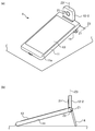
도 6(a)에서는, 도 1의 정보 처리 단말(1)의 연결부(12)(보다 정확하게는 카메라 기부(12-1))는, 회동축(Z1)을 중심으로 180 도 회동한 상태로 되어 있다. 도 6(b)에서는, 연결부(12)(보다 정확하게는 카메라 지향부(12-2))는, 도 6(a)의 상태로부터 더욱 회동축(Z3)을 중심으로(본체부(11)의 정면(11a)측에서 보아) 우측으로 90 도 회동한 상태로 되어 있다. 도 6(b)에 도시한 바와 같이, 카메라 지향부(12-2)의 정면(도 6(b)에서 보이고 있는 측의 면)의 대략 중앙에는 원 형상의 카메라(21)가 배치되어 있다. 도 6(c)에서는, 연결부(12)(보다 정확하게는 카메라 지향부(12-2))는, 도 6(a)의 상태로부터 더욱 회동축(Z3)을 중심으로(본체부(11)의 정면(11a)측에서 보아) 좌방으로 90 도 회동한 상태로 되어 있다. 도 6(c)에 도시한 바와 같이, 카메라 지향부(12-2)의 배면(정면과는 대향하는 면이며, 도 6(c)에서 보이고 있는 측의 면)의 대략 중앙에는 원 형상의 프로젝터(22)가 배치되어 있다. 또한, 도 3과 같이, 거리 h1와 거리 h2의 관계는, 상기의 식 (2)과 같은 관계이다.6A, the connection portion 12 (more precisely, the camera base 12-1) of the
도 6의 실시 형태의 정보 처리 단말(1)에서는, 회동축(Z2)에 의해 스탠드(14)는 본체부(11)에 대하여 회동하고, 회동축(Z1) 및 회동축(Z3)의 2 축에 의해 카메라(21)(연결부(12))는 표시부(13)(본체부(11))에 대하여 회동한다. 이 때문에, 유저는, 셀프 샷(본인 촬영) 등을 할 때에, 도 7에 도시한 바와 같이, 정보 처리 단말(1)을 탁상에 기대어 세워놓고 사용할 수도 있다.In the
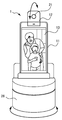
도 7은, 도 6의 정보 처리 단말(1)을 탁상에 기대어 세워놓고 사용하고 있는 모습을 도시하는 도면이다. 카메라(21)는, 유저(U)를 촬상한다. 이 카메라(21)의 촬상 화상, 즉 유저(U)의 상(Ug1)을 포함한 카메라 시점 화상은, 표시부(13)에 표시된다. 또한, 도 7에 도시한 바와 같이, 카메라 지향부(12-2)에는, 카메라(21)가 배치된 정면과 대향하는 배면에는 프로젝터(22)가 배치되어 있다. 이에 의하여, 프로젝터(22)는, 카메라(21)의 촬상 화상, 즉 유저(U)의 상(Ug2)을 포함하는 카메라 시점 화상을 스크린(Scr)에 투영할 수도 있다. 그 결과, 카메라 시점 화상은, 표시부(13)를 통하여 유저(U)에 시인될 수 있음과 동시에, 스크린(Scr)을 통하여 도시하지 않은 다른 사람에게 시인될 수도 있다.Fig. 7 is a diagram showing a state in which the
또한, 표시부(13)에 표시되는 화상과 프로젝터(22)에 의해 스크린(Scr)에 투영되는 화상은, 도 7의 예와 같이 반드시 일치시킬 필요는 특별히 없으며, 상이한 화상이어도 된다. 예를 들면, 화상 전화로서 정보 처리 단말(1)을 사용하는 경우라면, 표시부(13)와 스크린(Scr) 중 일방에, 유저(U)의 화상(카메라(21)의 카메라 시점 화상)을 표시시키고, 타방에 상대방 통화자의 화상을 표시시켜도 된다. 또한, 예를 들면, 카메라(21)와 프로젝터(22)는, 이와 같이 연결부(12)의 대향하는 위치에 배치하지 않아도, 같은 면에 배치해도 되고, 다른 면에 배치해도 된다.The image displayed on the
또한, 도 6 및 도 7의 예에서는, 동일한 가동부(카메라 지향부(12-2))에 카메라(21)와 프로젝터(22)가 탑재되어 있으므로, 카메라(21)의 촬상 방향과, 프로젝터(22)의 투영 방향의 일방이 제한을 받게 된다. 이에, 도시하지는 않았으나, 카메라 지향부(12-2)와는 별도의 가동부를 설치하고, 이 가동부에 프로젝터(22)를 탑재시키도록 해도 된다. 이에 의하여, 카메라(21)의 촬상 방향과, 프로젝터(22)의 투영 방향의 각각을 독립하여 임의의 방향을 향할 수 있게 된다.6 and 7, since the
또한, 예를 들면, 상술의 실시 형태에서는, 스탠드(14)는, 본체부(11)의 긴 방향과 수직인 위치에 있는 회동축(Z2)에서 회동하도록 되어 있었으나, 특별히 이에 한정되지 않는다. 도 8은, 본 발명의 정보 처리 단말의 일 실시 형태이며, 도 1 및 도 6과는 상이한 실시 형태의 탁상에서의 사용 모습을 도시하는 도면이다.Further, for example, in the above-described embodiment, the
도 8의 실시 형태의 정보 처리 단말(1)에 있어서는, 스탠드(23)는, 회동축(Z4)을 중심으로 배면(11b)측으로 약 50 도 회동시키고, 탁상에서 입설시키고, 또한 회동축(Z1) 및 회동축(Z3)도 회동시켜, 카메라(21)를 셀프 샷(본인 촬영) 가능한 방향으로 한 상태로 되어 있다. 스탠드(23)는, 본체부(11)의 단변과 대략 동일한 외형 치수이며, 본체부(11)와의 개도(開度)를 제로도로 함으로써, 본체부(11)와 형태적으로 일체화하여, 정보 처리 단말(1) 전체로서의 하단부를 구성한다.In the
회동축(Z4)은, 본체부(11)의 하나의 각부에 있어서, 본체부(11)와 스탠드(23)를 회동 가능하도록 연결한다. 회동축(Z4)은, 축 방향이, 본체부(11)의 장변에 대략 평행이며. 정보 처리 단말(1)의 자중 모멘트에 대항하여 자립 안정하도록, 적절한 회동 저항이 주어져 있다. 또한, 개도 90 도 이내의 몇 군데에, 회동이 도중에 정지되는 개소를 설치해도 된다.The pivot Z4 connects the
회동축(Z4)은, 적어도 배면(11b)측 90 도 이내에 스탠드(23)를 회동할 수 있고, 상술한대로, 본체부(11)와 스탠드(23)의 개도를 제로도로 할 수 있다. 상술한대로, 회동축(Z4)은, 축 방향이 본체부(11)의 장변에 대략 평행이므로, 유저는, 셀프 샷(본인 촬영) 등을 하기 위하여, 도 8에 도시한 바와 같이, 정보 처리 단말(1)을 탁상에 세워 횡 위치(랜드스케이프)에서 사용하는 경우의 회동축(Z4)의 회동각이, 본체부(11)의 입설각과 일치하여, 해당 각도의 조절이 용이하다.The turning shaft Z4 can rotate the
환언하면, 스탠드(23)는, 정보 처리 단말(1)을 탁상에 평평하게 둔 상태에서 탁상면에 둔 채로, 본체부(11)측을 일으켜서, 도 8의 사용 상태로 할 수 있다. 나아가서는 해당 상태로부터 본체부(11)측을 온화하게 탁상면으로 누름으로써, 정보 처리 단말(1)을 들어 올리지 않고, 보다 안정도 높은 평평하게 둔 상태로 이행시키는 것이 가능하다.In other words, the
또한, 이 스탠드(23)의 경우, 각도 조정을 세세히 할 수 있으므로, 피사체가 프론트 카메라 또는 1 축의 회동 카메라보다 위에 있으면, 2 축 카메라가 아니어도, 카메라를 완벽하게 피사체로 향하게 하는 것이 가능해진다.Further, in the case of the
도 9는, 도 1의 정보 처리 단말을 탁상에 기대어 세워놓고 사용하고 있는 모습을 도시하는 도면이다. 도 9(a)는, 탁상에 세로 위치(포트레이트)에서 기대어 세워놓고 사용하고 있는 모습을 나타내는 사시도이다. 도 9(b)는, 탁상에 세로 위치(포트레이트)에서 기대어 세워놓고 사용하고 있는 모습을 나타내는 측면도이다.Fig. 9 is a diagram showing a state in which the information processing terminal of Fig. 1 is laid on a desk. Fig. 9 (a) is a perspective view showing a state in which it is used standing upright from a vertical position (portrait) on a table. Fig. 9 (b) is a side view showing a state in which it is used while standing on a table at a vertical position (portrait).
도 9의 실시 형태의 정보 처리 단말(1)에 있어서는, 스탠드(14)는, 회동축(Z2)을 중심으로 배면(11b)측으로 90 도 미만으로 회동시켜, 탁상에 입설시키고, 또한 회동축(Z1)도 회동시켜, 카메라(21)를 세로 위치(포트레이트)에서 셀프 샷(본인 촬영) 가능한 방향으로 한 상태로 되어 있다. 예를 들면, 비디오 채팅에서의 이용에 있어서, 정보 처리 단말(1)을 쾌적하게 사용하기 위해, 통신의 상대방이 세로로 쥐고 촬상하고 있는지, 가로로 쥐고 촬상하고 있는지에 맞추어, 수신측도 세로로 쥠 또는 가로로 쥠을 전환할 수 있다.In the
만약, 통신의 상대방이 세로로 쥐고 촬상하고 있으나, 본인측이 정보 처리 단말(1)을 세로 위치에서 입설한 채로 본인 촬영을 행할 수 없는 경우, 본인측의 사용자는 정보 처리 단말(1)을 손으로 계속 쥐거나, 상대방에게 세로로 쥠을 멈추게 하여, 가로로 쥠의 촬영을 강요하거나, 또는 쌍방이 표시부에 서로의 화상이 작게 혹은 잘려서 표시되는 것을 감수해야 하게 된다. 그러나, 도 1의 정보 처리 단말(1)에서는, 스탠드(14) 및 촬영부의 회동 기구를 구비하므로, 주위에 적절한 벽면 및 매달아 지지 가능한 돌기물 또는 압정 등의 고정구가 없는 경우에도, 탁상에 세로 위치(포트레이트)에서 입설시켜 본인 촬영을 행할 수 있고, 그 결과, 세로 위치(포트레이트)에서 정보 처리 단말(1)을 손으로 계속 쥐는 부담 및 소지 촬상 시의 손 흔들림 등의 여러 문제로부터 한번에 해방되게 된다.If the person himself / herself can not take a picture of himself / herself while holding the
그런데, 회동축(Z1)을 회동시켜, 연결부(12)를 일으키면, 카메라(21)의 어플리케이션 프로그램이 자동으로 시작되는 것과 같은 구성으로 하면 된다. 이와 같이 함으로써, 돌연의 셔터 찬스에 대비하여, 카메라(21)의 어플리케이션 프로그램을 상시 기동할 필요가 없으며, 유한 귀중한 배터리 전원을 낭비하지 않아도 된다. 또한, 본체부(11)의 측면 등의 압하 조작이 용이한 위치로, 회동축(Z1)을 자동으로 회동시키는 「여는 버튼」을 설치하여, 압하 조작에 의해 간단하게 연결부(12)가 일어서는 기구를 채용해도 된다.Incidentally, the configuration may be such that the application program of the
통상, 타임 랩스의 사진이나 비디오를 찍을 때에는, 카메라를 삼각대로 고정하여, 일정 간격을 두고 촬영을 행하는 방법이 취해지고 있으나, 삼각대 등 많은 기재가 필요해진다고 하는 과제가 있다. 또한, 타임 랩스 촬영 시에 완전하게 카메라를 고정하는 것이 아니라, 예를 들면, 태양의 움직임에 맞추어, 카메라의 방향을 이동시켜 촬영하고자 하는 요망이 있으나, 그 때에는, 카메라를 이동시키는 돌리와 같은 기재가 더욱 추가로 필요해지고, 또한 그 설정도 카메라와는 별도로 필요하게 되어 버린다.Normally, when photographing a time-lapse photograph or video, there is a method of fixing the camera with a tripod and taking a picture at a predetermined interval, but there is a problem that a lot of equipment such as a tripod is required. Further, there is a demand to move the direction of the camera in accordance with the motion of the sun, for example, instead of fixing the camera completely at the time of the time-lapse photographing, but at this time, And further, the setting is also necessary separately from the camera.
그러나, 본 발명의 정보 처리 단말의 일 실시 형태에 의하면, 도 10에 도시한 바와 같이, 정보 처리 단말(1)은, 도 4 또는 도 5에 나타낸 바와 같이, 2 축 회전 기구를 가지고, 스탠드(14) 또는 카메라(21) 등을 구비함으로써, 삼각대 등의 고정용의 기재를 추가로 이용하지 않고, 카메라(21)를 고정하여, 창(MD)으로부터 보이는 태양(Sun)의 타임 랩스의 사진 또는 동영상을 촬영할 수 있다.However, according to the embodiment of the information processing terminal of the present invention, as shown in Fig. 10, the
또한, 도 10에 기재한 정보 처리 단말(1)은, 상술한 회동축(Z1~Z4)과 같은 복수의 회동축을 가지므로, 돌리와 같은 기재를 추가로 이용하지 않고, 태양(Sun)과 같이 저속으로 움직이는 것의 움직임에 맞추어 카메라의 방향이 움직이도록 사전에 설정하여, 타임 랩스의 사진이나 비디오를 촬영하는 것이 가능해진다.Since the
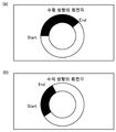
정보 처리 단말(1)은, 예를 들면, 도 11(a)에 도시하는 바와 같은 각도로, 카메라를 수평 방향으로 회전시키는 것이 가능하고, 도 11(b)에 도시하는 바와 같은 각도로, 카메라를 수직 방향으로 회전시키는 것이 가능하다.The
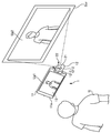
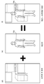
대상물의 사진을 찍을 때에, 예를 들면, 흐트러진 실내를 보여주고 싶지 않거나, 사람이나 상품에 주목을 받기 위해 흰색 배경으로 하고자 하는 등의 이유에 의하여, 대상물의 더욱 뒤의 배경은 숨기고자 하는 때가 있다. 종래에는, 카메라의 렌즈를 사용하여 흐려짐을 만들거나, 2 개 이상의 카메라를 사용하여 깊이를 계산하여 흐려짐을 만들었으나, 보통의 스마트폰의 하나의 카메라나 스마트폰의 렌즈의 경우, 정밀도 높게 배경을 깔끔하게 희미하게 하거나 지우는 것은 곤란했다. 그러나, 본 발명의 정보 처리 단말의 일 실시 형태에 의하면, 도 12 및 도 13에 도시한 바와 같이, 정보 처리 단말(1)이, 촬영 화상의 배경만을 깔끔하게 지우거나 희미하게 하는 것이 가능하다.When taking a picture of an object, for example, there is a time when it is desired to hide the background behind the object, for example, due to the fact that the user does not want to show a disordered room, . Conventionally, blurring has been made by using a camera lens or by calculating depth by using two or more cameras. However, in the case of a camera of a normal smartphone or a lens of a smart phone, It was difficult to fade neatly or erase. However, according to the embodiment of the information processing terminal of the present invention, as shown in Figs. 12 and 13, it is possible for the
우선은, 도 12(a)와 같이 대상(Obj)이 비친 화상을 촬영하고, 그 전후에 도 12(b)와 같이 대상(Obj)이 비치지 않은 배경만의 화상을 촬영한다. 또한, 도 12(a)의 화상과 도 12(b)의 화상의 차분만큼을 남김으로써, 도 12(c)와 같이, 상품이나 사람 등의 대상(Obj)만을 남긴 화상을 만들 수 있다. 또한, 도 12(c)와 같이, 대상(Obj)만을 남긴 화상을 만들 수 있다면, 그 화상을, 도 13(d)과 같이, 배경만의 화상을 희미하게 한 화상과 결합함으로써, 도 13(f)과 같이, 배경을 깔끔하게 희미하게 한 화상을 만들 수 있다. 또한, 동영상에 있어서도, 화상과 같은 처리를 함으로써 움직임이 있는 것만이 표시 가능하게 되어, 방범 카메라의 영상 해석 등에도 사용할 수 있다.First, as shown in Fig. 12 (a), an image of the object Obj is photographed, and before and after that, an image of only the background in which the object Obj is not irradiated is photographed as shown in Fig. 12 (b). In addition, by leaving only the difference between the image shown in Fig. 12 (a) and the image shown in Fig. 12 (b), it is possible to create an image leaving only the object Obj such as a product or a person as shown in Fig. 12 (c). 13 (c), if an image leaving only the object Obj can be made, the image is combined with an image in which only the background image is blurred as shown in Fig. 13 (d) As in f), you can create a cleanly blurred background. In addition, in the moving picture, only the motion can be displayed by performing the same processing as the picture, and the picture can also be used for the image analysis of the security camera.
예를 들면, 리노베이션을 행하기 전의 집의 사진과 행한 후의 사진을 비교하고자 하거나, 세제의 효과를 확인하기 위해 비교하고자 하는 등, 과거의 사진과의 비교 화상 또는 비교 영상을 촬영하고자 하는 때가 있다. 한편, 과거의 사진을 보면서, 같은 구도로 촬영할 수 있는 카메라나 스마트폰의 어플리케이션은 거의 존재하지 않는다.For example, there is a case where it is desired to compare a photograph of a house before a renovation and a photograph after a renovation, or to compare a comparison image or a comparison image with a photograph of the past, such as a comparison to confirm the effect of a detergent. On the other hand, there are very few applications of cameras and smart phones that can shoot in the same composition while viewing past photographs.
그러나, 본 발명의 정보 처리 단말의 일 실시 형태에 의하면, 간단하게 과거의 사진과의 비교 화상 또는 영상을 촬영할 수 있다. 도 14(a) 및 도 14(b)에 도시한 바와 같이, 정보 처리 단말(1)은, 과거의 사진 데이터를 반투명으로 표시할 수 있거나, 촬영하는 카메라의 라이브 뷰 화면으로부터 비교하고자 하는 사진을 1 버튼으로 표시할 수 있고, 또한 카메라의 라이브 뷰 화면으로 자동으로 되돌아오는 것 또는 1 액션(버튼을 누름, 리모콘의 버튼을 누름, 소리로 조작함 등)으로, 카메라의 라이브 뷰 화면으로 되돌아갈 수 있으므로, 간단하게 비교의 사진을 촬영하는 것이 가능해진다.However, according to the embodiment of the information processing terminal of the present invention, it is possible to simply photograph a comparison image or an image with a past photograph. As shown in Figs. 14 (a) and 14 (b), the
스마트폰이나 태블릿의 조작에 익숙해져 있는 사람에게 있어서, 보고 있는 아이콘을 직접 조작할 수 없는 UI(유저 인터페이스)는 이해하기 어렵다고 느껴지게 된다. 이에, Xperia touch와 같이, 프로젝터로 큰 화면에 투영할 수 있고, 투영한 스크린에도 터치로 조작을 할 수 있는 것이 시장에 생겨나고 있으나, 가격이 비싸고, 특정 거리 이상으로 투영 거리를 떨어뜨려 놓으면 터치를 할 수 없는 등의 제약도 많다. 또한, 화면이 크면 클수록, 터치하기 위해 스크린까지 행하여, 크게 손을 움직일 필요가 있으므로, 사용하기 쉽다고는 말하기 어렵다. 즉, 손에 화면마다 쥐고 행하는 근거리 조작과 화면이 멀어지고 있는 원거리 조작을 동일하게 하는 것은 무척 어렵다.For those who are accustomed to the operation of a smartphone or tablet, the UI (user interface) that can not directly manipulate the icon to be viewed feels difficult to understand. So, like Xperia touch, it is possible to project on a large screen with a projector, and it is possible for the market to operate the projected screen with a touch. However, if the price is high and the projection distance is decreased over a certain distance, There are many restrictions such as the inability to do. In addition, it is difficult to say that the larger the screen, the easier it is to use because it is necessary to move to the screen and to move the hand largely. In other words, it is very difficult to make the near distance operation held in the hand on the hand and the remote operation which is distant from the screen equal to each other.
그러나, 본 발명의 정보 처리 단말의 일 실시 형태에 의하면, 도 15에 도시한 바와 같이, 정보 처리 단말(1)의 표시부(13)에 표시되어 있는 영상을, 무선 또는 유선으로 TV 또는 프로젝터 등으로 대화면의 스크린으로 출력하고, 조작은, 레이저 포인터(LP) 등의 화면 상에 겹쳐 표시할 수 있는 디바이스에 의해 행할 수 있다. 이 때에, 예를 들면, 스크린(Scr) 상에 3 점 이상의 마커(24)를 영상의 일부로서 표시할 수 있다. 또한, 정보 처리 단말(1)의 카메라(21)로, 레이저 포인터(LP)의 커서(P)와 3 점 이상의 마커(24)를 촬영함으로써, 스크린(Scr) 상에서의 영상과 커서(P)의 상대적인 위치 관계를 알 수 있다. 레이저 포인터(LP)에는, 커서(P)의 On/Off 버튼 이외에도, 커서(P)의 확대·축소용의 버튼을 설치해도 되고, 또한 그 확대/축소용의 버튼은 커서(P)의 On/Off 버튼과 일체화해도 된다. 화면의 확대 시, 축소 시에, 커서의 색이나 형태가 바뀌는 등의 변화를 주어도 된다. 커서(P)는, 1 개라고는 한정할 수 없고, 복수 개를 동시에 판별해도 된다. 확대나 축소 조작 시에는, 2 개의 점이 멀어져 가면 영상을 확대하고, 2 개의 점이 가까워져 오면 영상을 축소한다고 하는 판단을 행할 수도 있다. 커서(P)를 알기 쉽게 정보 처리 단말(1)로 인식하기 위하여, TV 또는 프로젝터 등으로 출력하는 표시부(13)의 영상과 TV 또는 프로젝터 등에 비추어지고, 커서(P)도 비추어지고 있는 스크린 상의 영상을 리얼타임으로 촬영해 두고, 그 차분만큼을 남김으로써, 커서(P)의 궤적을 보다 알기 쉽게 인식할 수 있다. 정보 처리 단말(1)의 표시부(13)와 텔레비젼 수상기 또는 프로젝터로 출력하는 화면은 반드시 일치하고 있을 필요는 없음도 덧붙여 둔다. 예를 들면, 정보 처리 단말(1)의 표시부(13)에, 카메라(21)로 촬영하고 있는 화상을 표시해도 되고, 처리를 가볍게 하는 등의 목적으로, 억지로 아무것도 표시하지 않아도 된다.However, according to the embodiment of the information processing terminal of the present invention, as shown in Fig. 15, the image displayed on the
노트형 퍼스널 컴퓨터 등을 휴대하여, 이동처에서도 일을 하거나, 정해진 오피스나 자리를 가지지 않는 노마드 워커가 증가하고 있다. 그러나, 노트형 퍼스널 컴퓨터 등 운반할 짐이 많으면, 운반할 때에, 짐이 무거워지거나, 짐이 부피가 커져, 운반이 귀찮다. 한편, 퍼스널 컴퓨터를 운반하지 않고, 스마트폰만으로 일을 하고자 하면, 물리적인 키보드가 없으므로, 문자 입력에 시간이 걸려버리게 된다. 음성 입력도 가능해지고 있으나, 조용한 오피스에서는 사용할 수 없다. 전용의 박형의 키보드 등이 판매되고 있으나, 하나 하나 구입하는 것도 비용이 든다. 키보드를 제조하는 메이커에게 있어서는, 팔리지 않는 특정 언어용의 키보드를 제조하거나, 키보드의 커스터마이즈를 행하는 것은 현실적이지 않다고 하는 문제도 있다.Nomad walkers who do not have a fixed office or a place and work in a destination by carrying a notebook type personal computer are increasing. However, if there are many luggage to be carried, such as a notebook type personal computer, the luggage becomes heavy at the time of carrying, the luggage becomes bulky, and transportation is troublesome. On the other hand, if you do not carry a personal computer and want to work only with a smart phone, there is no physical keyboard, so that it takes time to input characters. Voice input is also available, but can not be used in a quiet office. Though thin keyboards are sold, it is also costly to buy them one by one. There is also a problem in that it is not realistic for a manufacturer of a keyboard to manufacture a keyboard for a specific language that is not sold or to customize the keyboard.
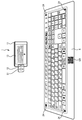
한편, 본 발명의 정보 처리 단말의 일 실시 형태에 의하면, 도 16에 도시한 바와 같이, 종이 등의 극박 소재에 인쇄된 키보드를 이용할 수 있으므로, 휴대성이나 제조 비용의 면에서 우수하다. 도 16의 정보 처리 단말(1)은, 스탠드(14)를 사용하고, 정보 처리 단말(1)을 세워 2 축의 카메라의 회전 기구를 사용함으로써, 카메라(21)를 고정하고, 인쇄된 키보드(K)를 촬영하고, 키보드(K) 위에 둔 손가락을 카메라로 촬영하여, 누른 손가락의 위치를 검지할 수 있다. 예를 들면, 키보드(K) 옆에 인쇄된 QR 코드(등록 상표)(QR)를 카메라(21)로 촬영함으로써, 인쇄된 키보드(K)의 버튼의 레이아웃을 1 개로 특정할 수 있도록 한다. 예를 들면, 3 점 이상의 마커(24)를 키보드(K) 옆에 인쇄함으로써, 키보드(K)의 버튼 영역을 지정할 수 있고, 키를 누른 버튼의 상대적인 위치도 알고, 인쇄된 키보드(K)로의 손가락의 압하로 문자 입력이 가능해진다. 키보드(K)는, 도 17에 도시하는 바와 같은 일반적인 배치의 것을 이용하는 것도 물론 가능하지만, 인쇄로 키보드(K)를 제조할 수 있으므로, 판매량을 신경쓰지 않고, 맘껏 커스터마이즈 할 수 있다. 예를 들어, 「안녕하세요」 「스즈키 이치로입니다」 「입니다」 「받겠습니다」 등의 버튼을 만듦으로써, 한 자 한 자 입력하는 것이 아니라, 정해진 어구의 단위로 입력시키는 것도 가능하다. 이것의 응용에 의하여, 게임 패드, 악기, 비디오 편집용의 믹서, DJ 믹서, 악기도 인쇄함으로써 만들 수 있다. 자필 문자 및 일러스트도 카메라로 촬영함으로써, 자필 입력도 가능해진다.On the other hand, according to the embodiment of the information processing terminal of the present invention, as shown in Fig. 16, since a keyboard printed on a very thin material such as paper can be used, it is excellent in portability and manufacturing cost. The
스마트폰을 책상 위에 두고, 스탠드 등으로 세우거나 하면, 스마트폰으로의 터치 조작을 할 때에, 본체의 디스플레이에 손을 대므로, 스마트폰 본체가 후방으로 이동하게 되거나, 스마트폰이 넘어지거나, 세운 스마트폰의 스탠드가 넘어지는 경우가 있다고 하는 문제가 있다.When a smartphone is placed on a desk and placed on a stand or the like, the user touches the display of the main body when touching with the smartphone, so that the main body of the smartphone moves backward, There is a problem that the stand of the smartphone may fall down.
한편, 본 발명의 정보 처리 단말의 일 실시 형태에 의하면, 도 18에 도시한 바와 같이, 정보 처리 단말(1)을 직접 조작하지 않고, 손가락(Fn)의 이동이나 책상으로의 터치 동작을 카메라(21)로 촬영함으로써, 손가락(Fn)의 움직임을 커서(P)의 움직임과 연동시켜, 퍼스널 컴퓨터의 터치 패드를 조작했을 때와 같이 조작할 수 있다. 마찬가지로, 예를 들면, 엄지를 붙인 채로, 집게 손가락을 상하로 움직이면, 마우스의 조그 다이얼과 움직이게 할 때와 같이 조작할 수 있다. 동일한 요령으로 자필 문자를 입력하는 것도 가능해진다.On the other hand, according to the embodiment of the information processing terminal of the present invention, as shown in Fig. 18, the movement of the finger Fn and the touch operation to the desk are performed by the
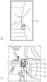
카 내비게이션 시스템으로서, 전용 기기를 사용하지 않고, 스마트폰의 네비게이션 어플리케이션으로 끝내는 사람도 많다. 그러나, 실제의 풍경과 지도로는 받는 인상이 상이한 등의 이유로, 길을 착각하는 경우도 있다. 그러한 길 착각을 막기 위하여, AR의 네비게이션이 있으나, AR 네비게이션으로서 사용하면, 스마트폰을 드라이버로부터 보기 어려운 각도로 설치해야 한다. 또는, 운전에 지장이 있는 위치에 설치해야 한다. 드라이브 레코더로서의 병용도 동일한 과제가 생겨난다.As a car navigation system, many people end up with a navigation application of a smartphone without using a dedicated device. However, there are cases where the road is mistaken for reasons such as differences in the impressions received from actual scenery and maps. In order to prevent such misunderstanding, there is AR navigation, but when used as AR navigation, the smart phone should be installed at a difficult angle from the driver. Or, it should be installed at a position that interferes with operation. The same problem arises in combination with a drive recorder.
한편, 본 발명의 정보 처리 단말의 일 실시 형태에 의하면, 도 19(a) 및 도 19(b)에 도시한 바와 같이, 정보 처리 단말(1)은, 복수의 회동축으로 회전할 수 있는 카메라(21)를 가지고 있다. 그 때문에, 이 정보 처리 단말(1)을 네비게이션 스탠드(25)로 고정하고, 카메라(21)로 AR 네비게이션이나 드라이브 레코더로서 차의 진행 방향의 영상을 촬영하고, 동시에 정보 처리 단말(1)의 표시부(13)를 드라이버에게 있어서 보기 쉬운 각도로 향할 수 있다.According to one embodiment of the information processing terminal of the present invention, as shown in Figs. 19 (a) and 19 (b), the
차 등의 운전 시, 드라이브 레코더나 카 내비게이션 시스템을 이용하는 것이 일반적으로 되어 있다. 이들 기기로는, 차의 움직임으로부터, 예를 들면, 졸음 운전을 하고 있을 가능성이 있거나, 음주 운전을 하고 있을 가능성이 있는 등, 운전자에게 무언가 문제가 있음을 예측할 수 있는 경우가 있다. 그러나, 어디까지나 차의 움직임으로부터 추측하고 있는 것에 지나지 않아서, 운전수의 상태를 직접적으로 조사할 수 없었다.It is general to use a drive recorder or a car navigation system when driving a car or the like. In these devices, there is a possibility that there is a problem in the driver, for example, there is a possibility that the vehicle is in the drowsy driving state, or the driver is driving in the alcoholic drink, for example, due to the movement of the vehicle. However, it was only possible to guess from the movement of the car, and the state of the driver could not be directly examined.
한편, 본 발명의 정보 처리 단말의 일 실시 형태에 의하면, 정보 처리 단말(1)의 카메라(21)는, 통상은 도 20(a)에 도시한 바와 같이, 통상은 진행 방향을 촬영하고 있으나, 위험 등을 찰지(察知)하면, 도 20(b)에 도시한 바와 같이, 카메라(21)가 회전하여 운전자의 얼굴 등을 촬영하여, 운전자의 건강 상태를 체크할 수 있다.On the other hand, according to the embodiment of the information processing terminal of the present invention, the
매일 입는 양복을 촬영할 수 있는 Amazon Echo look 등의 고정 카메라가 존재하고 있으나, 매회 촬영하는 위치를 조정하지 않으면, 촬영할 수 있는 인물의 크기가 각양각색이 되어 버리거나, 포즈도 저마다 다양해져, 깔끔하게 비교할 수 없다.There is a fixed camera such as Amazon Echo look that can shoot a suit every day, but if you do not adjust the position every time you shoot, the size of the person you can shoot becomes various, or the pose becomes diverse, so you can not compare it neatly .
한편, 본 발명의 정보 처리 단말의 일 실시 형태에 의하면, 도 21(a)에 도시하는 바와 같은 현재의 촬영 화상과, 예를 들면, 도 21(b)에 도시하는 바와 같은 전회의 사진을 비교하여, 대상(Obj)이 어울리는 위치로 오도록, 카메라(21)나 회전형 크래들(26)이 전동으로 회전하여 조정하거나, 동일한 포즈가 되도록, 포즈를 결정할 때의 가이드를 표시부(13)에 도시하거나 할 수 있다. 가이드로서는, 예를 들면, 스스로 자필 입력한 것을 표시할 수도 있다. 또한, 촬영과 동시에 건강 상태도 체크할 수 있고, 목소리나 제스쳐로 셔터를 누를 수도 있다.On the other hand, according to the embodiment of the information processing terminal of the present invention, the current photographed image as shown in Fig. 21 (a) is compared with the previous photographed image as shown in Fig. 21 (b) The
AR 보행자 네비게이션에 회전 카메라를 이용하고 있는 경우, 스마트폰의 방향이 바뀌면 카메라도 방향도 바뀌게 되어, 디스플레이를 보고 있는 사람이 멀미가 나게된다고 하는 문제가 생긴다.When using a rotating camera for AR pedestrian navigation, if the direction of the smart phone is changed, the direction of the camera also changes, causing a problem that the person watching the display becomes motion sickness.
한편, 본 발명의 정보 처리 단말의 일 실시 형태에 의하면, 도 22(a) 내지 도 22(c)에 도시한 바와 같이, 카메라(21)가, 회동축(Z1)을 이용하여 항상 일정한 방향(예를 들면, 수평 방향)을 향하도록 G 센서의 데이터 등을 이용하여 전기 제어함으로써, 정보 처리 단말(1)의 표시부(13)에 표시되는 화상을 일정하게 유지할 수 있게 된다.On the other hand, according to the embodiment of the information processing terminal of the present invention, as shown in Figs. 22 (a) to 22 (c), the
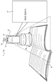
자신이 이해할 수 없는 언어로 쓰여진 서적을 읽기 위해서는, 그 언어를 습득하여 의미를 이해하거나, 자신의 언어로 번역될 때까지 기다릴 필요가 있어, 곧바로 읽고자 하는 사람에게 있어서는 큰 장애물이 있었다.In order to read a book written in a language that he can not understand, he had to learn the language and understand the meaning or wait until it was translated into his own language.
한편, 본 발명의 정보 처리 단말의 일 실시 형태에 의하면, 도 23에 도시한 바와 같이, 서적(B)을 카메라(21)로 촬영하여, OCR를 가함으로써, 텍스트 데이터를 인식하고, 번역을 정보 처리 단말(1)의 표시부(13)에 표시할 수 있게 된다. 서적(B)의 한 페이지 한 페이지를 하나 하나 셔터를 누르지 않고 정지 영상이나 동영상으로서 촬영하고, 페이지가 넘겨진 것을 트리거로 하여, 번역을 행한다. 페이지의 다시 읽어들임은, 음성으로 행해도 좋고, 소리로 행해도 된다. 물론, 이 기능을 사용함으로써, 서적(B)의 텍스트 데이터화도 가능해진다. 정보 처리 단말(1)은, 연결부(12)에 복수의 회동축을 가지므로, 표시부(13)의 방향에 의존하지 않고, 카메라(21)의 각도를 바꿀 수 있으므로, 이 기능이 가능해진다. 또한, 정보 처리 단말(1)을 회전형 크래들(26) 위에 둠으로써, 높이 방향의 거리를 벌 수 있어서 촬영하기가 쉬워지고, 한편, 회전형 크래들(26)의 회전과, 정보 처리 단말(1)의 각 회동축의 움직임을 조합함으로써, 촬영하는 서적(B)으로 카메라(21)의 방향을 적절히 맞출 수 있으므로, 보다 정밀도 높게 텍스트 데이터화가 가능해진다.On the other hand, according to the embodiment of the information processing terminal of the present invention, as shown in FIG. 23, the book B is photographed by the
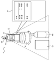
가게에서 회계를 행할 때에 사용하는 레지스터는, 업무용의 것이 일반적이지만, 그것은 매우 고액이며, 상품의 바코드 리더로 읽어들이거나, 상품에 붙어 있는 IC 태그를 검지하여 상품의 정보를 레지스터에 입력한다고 하는 공정이 필요해진다. 특히, 바코드 입력의 경우, 바코드의 위치를 맞추는 데에 수고가 드는 경우가 있으므로, 바코드 입력의 조작에 익숙함이 필요하다. 개인이 경영하는 빵 가게 등은, 빵 그 자체에 바코드를 붙일 수 없으므로, 레지스터에서 점원이 상품의 버튼을 손으로 입력하고 있다.The register used to carry out the accounting in the shop is common for business, but it is very expensive, and it is read by the bar code reader of the commodity, the IC tag attached to the commodity is detected, and the information of the commodity is inputted to the register . Particularly, in the case of bar code input, it takes time to adjust the position of the bar code, so it is necessary to be familiar with the operation of the bar code input. Since the bread shop which an individual manages can not attach the bar code to the bread itself, the clerk inputs the button of the product by hand in the register.
한편, 본 발명의 정보 처리 단말의 일 실시 형태에 의하면, 도 24에 도시한 바와 같이, 카메라(21)를 회전할 수 있는 정보 처리 단말(1)을 사용하거나, 또는 정보 처리 단말(1)을 회전형 크래들(26) 위에 두고, 정보 처리 단말(1)의 회전 기구와 조합하여 사용함으로써, 바코드의 위치에 맞추어, 카메라(21)의 방향이 자동으로 바뀌고, 예를 들면, 초콜릿(Ch), 패트병(Pb) 등의 구입할 상품의 바코드를 높은 정밀도로 읽어낼 수 있게 된다. 또한, 상품의 형상 등의 특징을 사전에 인식시킴으로써, 빵 등의 바코드가 붙어있지 않은 상품에서도, 상품명, 가격 등의 정보를 알 수 있게 될 수 있다.On the other hand, according to the embodiment of the information processing terminal of the present invention, as shown in Fig. 24, the
상품 구입 시의 영수증 또는 영수서를 카메라로 촬영함으로써, 가계부 또는 장표(帳票)의 입력을 간략화하는 것이 가능하게 되어 있으나, 촬영을 위해서는, 영수증을 두고, 카메라를 구비하여 셔터를 누를 필요가 있으므로, 매우 수고가 든다.It is possible to simplify the input of the household part or the bill slip by photographing the receipt or receipt at the time of purchase of the goods with the camera. However, since it is necessary to put the receipt and the camera and press the shutter for photographing, It takes effort.
한편, 본 발명의 정보 처리 단말의 일 실시 형태에 의하면, 도 25에 도시한 바와 같이, 카메라(21)를 회전할 수 있는 정보 처리 단말(1)을 책상 위의 회전형 크래들(26) 위에 둠으로써, 높이 방향의 거리를 벌 수 있고, 한편, 회전형 크래들(26)의 회전과, 정보 처리 단말(1)의 회전을 조합함으로써, 책상 위의 영수증의 한 개 한 개를(셔터 압하와 같은) 조작을 하지 않고, 자동으로 촬영할 수 있다. 촬영이 가능하다면, 반드시 회전형 크래들(26)은 필요하지 않다. 촬영된 영수증, 영수서 등에 OCR를 가함으로써, 텍스트 데이터를 인식하여 입력할 수 있게 된다. 유저는, 정보 처리 단말(1) 또는 회전형 크래들(26)을 거의 조작할 필요가 없이, 영수증이나 영수서를 놓는 것에 집중하는 것만 하면 된다. 특히, 책상과 같은 평면 위에서 하면, 영수증이나 영수서를 늘어놓기 쉽다.On the other hand, according to the embodiment of the information processing terminal of the present invention, as shown in Fig. 25, the
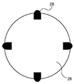
상품을 옥션 어플리케이션이나 프리마켓 어플리케이션 등에 게재할 때에는, 상품의 상태를 알고자 하는 구입자를 위하여, 다양한 각도에서 사진을 찍을 필요가 있으므로, 출품하는 수고의 하나로 되어 있었다.When a product is placed in an auction application or a flea market application, it is necessary to take a picture at various angles for a purchaser who wants to know the state of the product.
한편, 본 발명의 정보 처리 단말의 일 실시 형태에 의하면, 도 26에 도시한 바와 같이, 회전형 크래들(26)에 윗면 어태치먼트를 고정함으로써, 회전형 크래들(26)의 위에 촬영하고자 하는 상품을 두고, 스탠드(14)로 고정된 정보 처리 단말(1)의 카메라(21)를 이용하면서, 정보 처리 단말(1)로부터 회전형 크래들(26)의 회전을 컨트롤 하여, 360 도의 상품 촬영이 가능해진다.On the other hand, according to the embodiment of the information processing terminal of the present invention, as shown in Fig. 26, by fixing the top attachment to the
의류를 옥션이나 프리마켓의 어플리케이션 소프트웨어 등에 게재할 때에는, 상품의 상태를 알고자 하는 구입자를 위하여, 다양한 각도에서 사진을 찍을 필요가 있으므로, 출품하는 수고의 하나로 되어 있었다. 양복 등은, 매달아 촬영하므로, 도 26과는 다른 해결책이 필요해진다.When placing clothes on auction software or application software on a flea market, it is necessary to take pictures at various angles for purchasers who want to know the status of the products, and it has become one of the labor of exhibiting. Since the clothes and the like are photographed by hanging, a solution different from that in Fig. 26 is required.
한편, 본 발명의 정보 처리 단말의 일 실시 형태에 의하면, 도 27에 도시한 바와 같이, 회전형 크래들(26)에 매달음 어태치먼트(27)를 고정함으로써, 회전형 크래들(26)의 아래에, 물건을 행거 등으로 매다는 것이 가능해진다. 매단 상품을, 스탠드(14)로 고정된 정보 처리 단말(1)의 카메라(21)를 이용하면서, 정보 처리 단말(1)로부터 회전형 크래들(26)의 회전을 컨트롤하여, 360 도의 상품 촬영이 가능해진다.On the other hand, according to the embodiment of the information processing terminal of the present invention, the
디지털 카메라나 스마트폰에서도 카메라를 가로 이동함으로써, 합성의 파노라마 샷을 찍을 수 있으나, 매끄럽게 카메라나 스마트폰을 가로 이동시킬 필요가 있으므로, 깔끔하게 합성할 수 없는 경우가 많다. 또한, 가로 이동뿐만 아니라 세로 이동도 할 수 있으면, 좀더 큰 사진을 합성할 수 있으나, 이것도 깔끔하게 합성할 수 없다.In digital cameras and smartphones, it is possible to take a panoramic shot of a composite by moving the camera horizontally, but since it is necessary to smoothly move the camera or smartphone horizontally, it is often impossible to synthesize neatly. Further, if it is possible to move not only the horizontal movement but also the vertical movement, a larger picture can be synthesized, but this can not be neatly synthesized.
한편, 본 발명의 정보 처리 단말의 일 실시 형태에 의하면, 복수의 회동축을 움직여 정보 처리 단말(1)의 카메라(21)를 조작함으로써, 도 28에 도시한 바와 같이, 세로 방향 및 가로 방향의 파노라마 촬영이 가능하게 되어, 보다 큰 사진을 촬영할 수 있다. 또한, 정보 처리 단말(1)을 회전형 크래들(26)의 위에 둠으로써, 정보 처리 단말(1)의 회동축을 이용하여 촬영 포인트를 세로 방향으로 이동하여, 회전형 크래들(26)의 가로 회전을 맞추어 이용하는 등 하여, 정보 처리 단말(1)의 회동축만을 이용한 경우보다, 더욱 광범위한 영역을 촬영할 수도 있다. 전동으로 촬영할 수 있으므로, 깔끔하게 합성하는 것이 가능해진다. 가로 세로의 합성을 행할 수 있으면, 보다 큰 사진을 촬영할 수 있다. 스캔할 때에, 몇 글자 쓰기의 요령으로 스캔하는 순서를 정해가면 낭비가 없다.On the other hand, according to the embodiment of the information processing terminal of the present invention, by operating the
인터넷의 비디오 채팅 등을 통하여, 수업을 행할 때 등, 종이에 쓴 것을 상대에게 전하고자 할 때가 있다. 상대가 쓴 것은, 다 쓴 후에, 카메라에 비추는 것이 일반적이지만, 그렇다면 도중의 과정을 잘 모른다고 하는 과제가 있다.Through video chatting on the Internet, there are times when you want to tell your opponent what you have written on paper, such as when you are in class. It is common for the opponent to write on the camera after they have written it, but there is a problem that they do not know the course on the way.
한편, 본 발명의 정보 처리 단말의 일 실시 형태에 의하면, 도 29(a)에 도시한 바와 같이, 교사(Tc)측의 정보 처리 단말(1)의 카메라(21)를 회전시킴으로써, 셔터를 누르지 않고, 책상 위의 서적(B)을 자동으로 촬영하여, 사다리꼴 보정, 상하 반전을 행한 후, 도 29(b)에 도시한 바와 같이, 학생측의 정보 처리 단말(1)의 표시부(13)에 서적(B)이나 교사(Tc)의 얼굴을 동시에 표시하는 것도 가능해진다. 그 때에는, 책상에서부터 카메라까지의 높이가 충분하지 않고, 종이를 전부 촬영할 수 없을 때에는, 정보 처리 단말(1)을 세로 방향으로 세울 수 있는 스탠드 등을 이용하면 된다. 또한, 회전형 크래들(26)을 사용하면, 높이 방향의 거리를 벌 수가 있고, 정보 처리 단말(1)의 카메라 회전 기능은, 카메라의 세로 회전에 이용하여, 회전형 크래들(26)의 가로 회전을 맞춤으로써, 정보 처리 단말(1)의 회전보다 더욱 광범위한 영역을 촬영할 수도 있다. 이를 응용하여, 리모콘에 의한 카메라 조작 및 회전을 행하거나, 네트워크를 초월한 조작도 가능해진다. 또한, 프라이버시를 지키기 위해, 카메라의 움직임에 제한을 두거나, 촬영하고 있는 것을 나타내는 표시를 붙일 수도 있다. 예를 들면, 네트워크를 초월한 조작(카메라(21)의 방향을 바꿈)을 할 수 없는 것과 같은 설정을, 조작되는 측의 기기(카메라나 스마트폰 등)로부터 행하는 것도 가능하다. 촬영을 하고 있음을 알 수 있도록, LED, 표시 화면, 플래쉬 라이트를 발광하거나, 바이브래이터 또는 소리를 울리고, 냄새를 풍기고, 촬영하고 있는 화상을 디스플레이에 표시하는 것도 가능하다. 또한, 조작을 행하기 위해 패스워드의 입력을 필요로 할 수도 있다. LED를 발광시키거나, 촬영 중의 화상의 표시를 행하지 않는 설정도 조작되는 측, 조작을 받는 측의 어느 쪽에서도 행할 수 있고, 행할 수 없는 것과 같은 설정도 가능하다.On the other hand, according to the embodiment of the information processing terminal of the present invention, as shown in Fig. 29 (a), by rotating the
파티나 회식 등의 자리에서, 그 모임의 모습의 사진을 찍을 때에는, 셔터를 누르는 카메라맨이 되는 사람이 필요했다. 자동으로 촬영을 행해주는 로보트 펀치 루터도 있으나, 어디에 사람이 있는지 모르며, 어림짐작으로 회전하므로, 좀처럼 좋은 구도의 사진이 찍히지 않았다.When we took photograph of state of meeting in party such as party and meal, person who became cameraman to press shutter was necessary. There is a robot punch luther that shoots automatically, but I do not know where people are, and since I guessed it, I could not take a picture of a good composition.
한편, 본 발명의 정보 처리 단말의 일 실시 형태에 의하면, 도 30에 도시한 바와 같이, 카메라(21)가 회전 가능한 정보 처리 단말(1)을 책상 위의 회전형 크래들(26) 위에 둠으로써, 회전형 크래들(26)의 회전과, 정보 처리 단말(1)의 카메라(21)의 회전을 조합하여, 모든 방향으로 카메라(21)를 향하는 것이 가능해진다. 도 31에 도시한 바와 같이, 회전형 크래들(26) 또는 정보 처리 단말(1)에 내장한 사람 감지 센서(28)로 사람이 있는 위치를 특정한 후, 카메라(21)를 회전시키므로, 어림짐작으로 회전하지 않고, 사람을 확실히 촬영하는 것이 가능해진다. 회전형 크래들(26)이 없어도, 2 축 이상 회전할 수 있는 정보 처리 단말(1)의 카메라(21)가 있으면 자동 촬영이 가능해진다.On the other hand, according to the embodiment of the information processing terminal of the present invention, by placing the
사람 감지 센서(28) 이외에도, 예를 들면, 마이크로폰을 복수 탑재함으로써, 소리가 마이크로폰으로 들어오는 미묘한 시간 차를 계산하는 등 하여, 위치를 특정하는 것이 가능해진다. 회전 기구를 응용하고, 대상물을 결정하고, 카메라를 자동 추적시키는 것도 가능해진다. 촬영은 반드시 모두 자동으로 행할 필요는 없으며, 소리로 촬영을 해도 되고, 제스쳐로 촬영해도 된다. 사람을 판단하여, 사진찍기를 원치 않는 사람이 있으면, 자동으로 판별하여 사진을 찍지 않는 것과 같은 설정도 가능하다. 사진을 찍히고 싶지 않은 사람을 사전에 카메라로 등록해 두거나, 촬영 중에 손으로 Х 마크를 만들면 촬영하지 않는 등, 화상 처리로 판단시키는 것도 가능하다.In addition to the
크래들은 원래 스마트폰에 대하여, 충전을 위한 전력을 공급하는 것이 주 목적의 하나이므로, 스마트폰으로부터 전력을 받지 못하고, 크래들에 내장된 기능을 움직이기 위해, 전지나 AC 아답터 등의 전원이 필요하게 되어, 매우 짧은 시간을 위해서도 전지 또는 AC 아답터를 운반해야 한다.Since the cradle is one of the primary purposes of supplying power for charging the smartphone, Without power from the smartphone, you will need a battery or AC adapter to power the cradle's built-in functions, and you will need to carry a battery or AC adapter for a very short time.
한편, 본 발명의 정보 처리 단말의 일 실시 형태에 의하면, 회전형 크래들(26)에 전원이 공급되어 있지 않은 것을 자동으로 판단하고, 정보 처리 단말(1)로부터 회전형 크래들(26)에 전원 공급을 행함으로써, 회전형 크래들(26)에 붙어 있는 사람 감지 센서(28) 등의 기능을 정보 처리 단말(1)의 전원으로 움직이게 할 수 있게 된다.On the other hand, according to the embodiment of the information processing terminal of the present invention, it is automatically determined that no power is supplied to the
스마트폰을 퍼스널 컴퓨터처럼 사용할 수 있도록, HDMI(등록 상표)의 단자를 붙여, 영상 출력을 가능케 하거나, USB의 A 단자를 탑재하는 등 하여, 크래들에 다양한 기능을 포함하는 경우가 있다. 그러나, 스마트폰의 인카메라는, 크래들이 놓여있는 위치, 방향, 또는 각도에 의하여, 퍼스널 컴퓨터의 인카메라처럼은 사용할 수 없는 경우가 많다. 왜냐하면, 원래 스마트폰의 인카메라를 사용할 수 있는 것과 같은 기능이 없거나, 퍼스널 컴퓨터의 인카메라는, 디스플레이 위 또는 아래에 붙어 있고, 디스플레이를 향하면, 인카메라에도 얼굴을 향한 것이 되지만, 스마트폰을 퍼스널 컴퓨터처럼 사용하는 경우에는, 얼굴은, 접속된 모니터를 향하므로, 크래들에 놓인 스마트폰을 본다고는 한정할 수 없고, 크래들의 각도에 의하여, 인카메라가 향하는 각도도 정해지므로, 따라서, 하나 하나 스마트폰의 크래들의 위치나 방향을 바꿀 필요가 있다.In some cases, the cradle may include various functions such as attaching a terminal of HDMI (registered trademark) so as to enable a smart phone to be used as a personal computer, or to output video, or to mount an A terminal of USB. However, due to the position, orientation, or angle of the cradle, which is called the smartphone's in-camera, it is often impossible to use the smartphone as an in-camera of a personal computer. This is because, if there is no function such as the ability to use the in-camera of the original smartphone, or if the in-camera of the personal computer is on or under the display and faces the display, The face faces the connected monitor, so that it is not always possible to view the smartphone placed on the cradle, and the angle at which the in-camera faces is determined by the angle of the cradle. Therefore, It is necessary to change the position or direction of the cradle.
한편, 본 발명의 정보 처리 단말의 일 실시 형태에 의하면, 도 31에 도시하는 바와 같은 사람 감지 센서(28)가 붙은 회전형 크래들(26)에, 정보 처리 단말(1)을 두면, 카메라(21)가 자동적으로 시작되고, 촬영 대상이 카메라(21)에 들어가도록 회전형 크래들(26) 또는 정보 처리 단말(1)의 회동축이 구동하여, 촬영 대상이 카메라에 들어가도록 할 수 있다. 퍼스널 컴퓨터의 인카메라처럼 사용할 수 있을 뿐만이 아니라, 그 카메라(21)의 영상을 얼굴 인증에 사용할 수 있거나, 사람 감지 센서(28)를 사용하여, 사람이 없을 때에는 모니터를 끄는 등, 다양한 것이 가능해진다.On the other hand, according to the embodiment of the information processing terminal of the present invention, when the
또한, 이러한 회전형 크래들(26)에는, 예를 들면, 복수의 마이크로폰, 복수의 스피커, 복수의 사람 감지 센서, 스위벨 기능, 모바일 배터리 등을 내장할 수 있다. 이에 의하여, 회전형 크래들(26)에 탑재된 정보 처리 단말은, 정보 표시, 음악 재생, 뉴스의 재생, 일기 예보, 오디오 북, 캘린더, 스포츠 속보, 교통 정보, 쇼핑, 전기, 에어콘, 커텐과의 연동 등, 다양한 것에 이용 가능해진다.The
그런데, 본 발명의 정보 처리 단말에 있어서, 본체부(11)와 연결부(12)는, 회동 가능하도록 상호 접속되어 있는 것은 상술한 바와 같다. 이 연결부(12)의 회동 조작은, 수동이여도 되고, 전동이여도 된다. 연결부(12)의 회동 조작이 전동화되는 경우, 정보 처리 단말은, 예를 들면, 도 32와 같이 구성된다. 도 32는, 본 발명의 정보 처리 단말의 일 실시 형태의 외관 및 내부의 구성이며, 도 2 등과는 상이한 구성을 나타내고 있다. 도 32(a)는, 정보 처리 단말의 배면도이다. 도 32(b)는, 도 32(a)의 단면도이다. 연결부(12)는, 도 2와 마찬가지로, 카메라 기부(12-1)와, 카메라 지향부(12-2)를 가지고 있다. 카메라 지향부(12-2)의 정면(도 32(a)에서 보이고 있는 측의 면)에는 원 형상의 카메라(21)가 배치되어 있다.Incidentally, in the information processing terminal of the present invention, the
카메라 기부(12-1)는, 회동축(Z1)을 회동 중심으로 하여 본체부(11)에 대하여 연결부(12) 전체를 전동 가능하게 회동 가능하도록 축지된다. 즉, 카메라 기부(12-1)는, 주형의 외형 중의 단면을 본체부(11)에 접힘 접촉(摺接)하면서, 회동축(Z1)을 중심으로 하여 회동할 수 있도록 구성된다. 이 회동축(Z1)에서의 자동적인 회동을 가능케 하도록, 스테핑 모터(51)와, 2 축 힌지(53)와, 기어(54)와, 기어(55)가, 연결부(12)의 내부에 설치되어 있다(도 32(b) 참조). 즉, 스테핑 모터(51)의 회전 구동력이, 2 축 힌지(53)에 전달됨으로써, 카메라 기부(12-1)는 회동축(Z1)을 중심으로 하여 자동적으로 회동한다.The camera base 12-1 is axially rotatable about the
카메라(21)가 탑재되는 카메라 지향부(12-2)는, 회동축(Z1)에 대하여 대략 직교 방향으로 배치된 회동축(Z3)을 회동 중심으로 하여 카메라 기부(12-1)에 대하여 회동 가능하도록 외팔보로 축지된다. 이 회동축(Z3)에서의 자동적인 회동을 가능케 하도록, 스테핑 모터(52)와, 2 축 힌지(53)와, 기어(54)와, 기어(56)가, 연결부(12)의 내부에 설치되어 있다(도 32(b) 참조). 즉, 스테핑 모터(52)의 회전 구동력이, 기어(54) 및 기어(56)를 통하여, 2 축 힌지(53)에 전달됨으로써, 카메라 지향부(12-2)는 회동축(Z3)을 중심으로 하여 자동적으로 회동한다. 말할 필요도 없이, 2 축 힌지(53)는 반드시 일체형의 2 축 힌지일 필요는 없고, 힌지가 2 개로 분할되어 있어도 된다.The camera directing part 12-2 on which the
이와 같이, 스테핑 모터(51) 및 스테핑 모터(52)를 채용함으로써, 회동축(Z1) 및 회동축(X3)에서의 회동이, 고정밀도 및 고속으로 전동으로 행할 수 있게 된다.By employing the stepping
도 33은, 도 32의 스테핑 모터(51) 및 스테핑 모터(52)를 채용한 경우에 있어서의, 회동축(Z1) 및 회동축(Z3)에서의 회동의 제어를 실현하기 위한 구성을 나타내는 블럭도이다. 스테핑 모터(51) 및 스테핑 모터(52)를 채용한 경우에 있어서의, 회동축(Z1) 및 회동축(Z3)에서의 회동의 제어를 실현하기 위해, 스테핑 모터(51)의 모터 드라이버(61) 및 스테핑 모터(52)의 모터 드라이버(62), 스테핑 모터(51)의 회전각 센서(63) 및 스테핑 모터(52)의 회전각 센서(64), MCU(Micro Controller Unit)(65) 및 무선 모듈(66)이 설치되어 있다. 또한, 이들 블록 등은, 설명의 편의 상, 정보 처리 단말(1)의 외부에 도시되어 있으나, 정보 처리 단말(1)에 내장되어도 된다. MCU(65)에는, 무선 모듈(66)과의 인터페이스가 되는 드라이버(71)와, 정보 처리 단말(1)의 인풋 디바이스(82)와의 인터페이스가 되는 드라이버(72)와, 모터 드라이버(61)와의 인터페이스가 되는 드라이버(73)와, 모터 드라이버(62)와의 인터페이스가 되는 드라이버(74)가 설치되어 있다. MCU(65)에는 또한, 회전각 센서(63, 64)의 각각의 아날로그의 검출 신호를 디지털 신호로 변환하기 위하여, ADC(Analog to Digital Converter)(75, 76)의 각각이 설치되어 있다.33 is a block diagram showing a configuration for realizing the control of the rotation on the rotary shaft Z1 and the rotary shaft Z3 in the case of employing the stepping
회동축(Z1) 및 회동축(Z3)에서의 회동의 지시(카메라(21)의 이동 지시)는, 와이어리스 리모콘(81) 등을 이용한 유저의 지시(OP1)와, 정보 처리 단말(1)의 터치 패널 등의 인풋 디바이스(82)를 이용한 유저의 지시(OP2)의 각각에 의해 행해진다. 지시(OP1)에 의한 지시는 MCU(65)의 드라이버(71)에, 지시(OP2)에 의한 지시는 MCU(65)의 드라이버(72)에, 각각 입력된다.The instructions of the rotation (movement instruction of the camera 21) on the rotary shaft Z1 and the rotary shaft Z3 are made by the instruction OP1 of the user using the wireless
MCU(65)는, 지시(OP1)에 의한 지시와, 회전각 센서(63, 64)의 각각의 검출 신호에 기초하여, 드라이버(73, 74) 각각을 통하여, 모터 드라이버(61, 62) 각각에 대한 제어를 실행한다.The
이와 같이 2 개의 회전각 센서(63, 64)를 채용함으로써, 다음의 점이 가능해진다. 즉, 첫번째는, 절대 위치를 아는(유저의 손으로 작동되거나 하면 계산으로 위치를 낼 수 없으므로) 경우가 생기는 점이다. 두번째는, 가동 범위 외까지 움직이지 않도록 하기 위한 Fail Safe가 가능하게 되는 점이다. 세번째는, 본체의 G 센서와 회전각 센서(63, 64)를 조합함으로써, 카메라(21)의 방향을 정밀도 좋게 산출할 수 있는 점이다.By employing the two
이와 같이, 본 발명이 적용되는 정보 처리 단말은, 다양한 실시 형태를 취하는 것이 가능하다. 환언하면, 본 발명이 적용되는 정보 처리 단말은, 다음과 같은 구성을 취하면 충분하며, 그 실시 형태는 특별히 한정되지 않는다. 즉, 본 발명이 적용되는 정보 처리 단말은, 피사체를 촬상하는 촬상부(예를 들면, 도 2의 카메라)와, 상기 촬상부에 의해 촬상되는 상기 피사체를 포함한 촬상 화상을 표시하는 표시부(예를 들면, 도 1 또는 도 2의 표시부(13))가 소정의 일면(예를 들면, 도 1 또는 도 2의 정면(11a))에 배치된 본체부(예를 들면, 도 1 또는 도 2의 본체부(11))와, 상기 촬상부의 광축 방향과 상기 표시부의 법선 방향이 이루는 각도를 변화시키는 제1 회전축(예를 들면, 도 2의 회동축(Z1))과, 상기 제1 회전축과는 다른 방향의 제2 회전축(예를 들면, 도 2의 회동축(Z3))을 포함한 복수의 회전축에 의하여, 상기 촬상부를 상기 본체부에 대하여 상대적으로 회동 가능하도록, 직접적 또는 간접적으로 연결하는 연결부(예를 들면, 도 1 또는 도 2의 연결부(12))를 구비한다.As described above, the information processing terminal to which the present invention is applied can take various embodiments. In other words, the information processing terminal to which the present invention is applied may suffice if it has the following configuration, and the embodiment is not particularly limited. That is, the information processing terminal to which the present invention is applied includes an imaging unit (for example, the camera shown in Fig. 2) for imaging an object, a display unit for displaying a sensed image including the object to be imaged by the imaging unit (For example, the
또한, 상기 연결부는, 상기 본체부보다 용적이 작은 가동부(예를 들면, 도 2의 카메라 기부(12-1)와 카메라 지향부(12-2))를 하나 이상 가지고 있고, 상기 촬상부는, 하나 이상의 상기 가동부 중, 소정의 하나(예를 들면, 카메라 지향부(12-2))의 소정의 면에 배치되고, 상기 제1 회전축의 방향과 상기 제2 회전축의 방향이 이루는 각도는, 대략 90 도가 되게 할 수 있다.The connecting portion has at least one movable portion (for example, the camera base portion 12-1 and the camera directing portion 12-2 in Fig. 2) having a smaller volume than the main body portion, The angle formed by the direction of the first rotation axis and the direction of the second rotation axis is set to be substantially 90 (for example, 90 degrees) It can be done.
또한, 상기 본체부와 2 개 이상의 가동부는, 2 축 이상의 힌지로 연결하도록 할 수 있다.In addition, the main body and the two or more movable parts may be connected by a hinge of two or more axes.
또한, 상기 본체부와 가동부는, 플렉서블 암으로 연결하도록 할 수 있다.The main body and the movable part may be connected by a flexible arm.
또한, 본체부의 긴 방향과 수직인 위치에 있는 회동축(예를 들면, 회동축(Z1))을 중심으로 카메라부가 회동하는 경우에, 더 이상 회동하지 않는 위치까지 회동하기 전에, 멈추는 장소가 있게 할 수 있다.Further, when the camera unit rotates about the pivot axis (for example, the pivot axis Z1) at a position perpendicular to the longitudinal direction of the main body, there is a stopping position before turning to the position where it is no longer turning can do.
또한, 본체부의 긴 방향과 수직인 위치에 있는 회동축(예를 들면, 회동축(Z1))을 중심으로 연결부가 회동하는 경우에, 180 도를 크게 초과하여, 카메라부가 회동하도록 할 수 있다.Further, when the connecting portion rotates about the pivot axis (for example, the pivot axis Z1) at a position perpendicular to the longitudinal direction of the main body portion, the camera portion can be rotated by exceeding 180 degrees.
또한, 카메라를 붙인 가동부(예를 들면, 카메라 지향부(12-2))에 상하 좌우 방향을 판별하기 위한 가속도 센서 등이 붙어 있고, 그 센서의 값에 의하여, 표시부의 화상의 방향으로 영향이 있게 할 수 있다. 구체적으로는, 예를 들면, 본체부(11)의 상하 좌우 방향을 판별하기 위한 가속도 센서 등이, 본체부(11)측에도 붙어 있는 경우는, 본체부(11)의 방향과 카메라 지향부(12-2)의 방향을 감안하여, 카메라 시점 화상을 표시한다. 그 밖의 수법으로서, 본체부(11)와 카메라 지향부(12-2)의 각도를 단수 또는 복수의 센서에 의해 계산하고, 본체부(11)에 탑재되어 있는 가속도 센서 등의 값과 조합하여, 카메라 지향부(12-2)의 방향을 감안하여, 카메라 시점 화상을 표시하는 수법을 채용할 수도 있다.An acceleration sensor or the like is attached to a moving part (for example, the camera directing part 12-2) to which the camera is attached, and the influence of the acceleration sensor or the like on the direction of the image of the display part You can do it. Specifically, for example, when an acceleration sensor or the like for identifying the up-and-down and left-right direction of the
또한, 본체부를 지표에 평행 또는 수직으로 두는 것이 아니라, 다른 각도로 고정할 수 있는 스탠드의 구조가 있게 할 수 있다.Further, it is possible to provide a structure of the stand which can be fixed at different angles, not in parallel or perpendicular to the surface of the body.
또한, 이에 가세하여, 그 스탠드에 회동축(예를 들면, 회동축(Z2))이 있어, 스탠드가 본체와 평행한 위치까지 180 도 회전하도록 할 수 있다.In addition, in addition to this, a pivot shaft (for example, a pivot axis Z2) is provided on the stand so that the stand can be rotated 180 degrees to a position parallel to the main body.
또한, 변형예로서, 최초부터 본체부와 카메라부를 분리할 수 있게 할 수 있다.As a modified example, it is possible to separate the main body and the camera from the beginning.
또한, 그 때에는, 분리한 카메라부에 가동부를 1 개 이상 가지고 있어, 카메라의 촬상부의 광축 방향을 변화시키는 제1 회전축과, 제1 회전축과는 다른 방향의 제2 회전축을 포함한 복수의 회동축에 의해 카메라를 회동 가능케 하여, 제1 회전축의 방향과 제2 회전축의 방향이 이루는 각도는 대략 90 도가 되게 할 수 있다.At this time, the separated camera section has at least one movable section, and the first rotating shaft for changing the optical axis direction of the image pickup section of the camera and the second rotating shaft for rotating the second rotating shaft in the direction different from the first rotating shaft So that the angle formed by the direction of the first rotation axis and the direction of the second rotation axis can be made to be about 90 degrees.
또한, 가동부가 전동으로도 회동하도록 할 수 있다.Further, the movable portion can also be rotated by electric power.
또한, 분리한 카메라에 상하 좌우 방향을 판별하기 위한 가속도 센서 등이 붙어 있고, 그 센서의 값에 의하여, 표시부의 화상의 방향으로 영향이 있게 할 수 있다.In addition, an acceleration sensor or the like for discriminating the up, down, left, and right directions is attached to the separated camera, and the direction of the image of the display portion can be influenced by the value of the sensor.
또한, 촬영 후에 간단하게 문자를 쓰거나 편집할 수 있도록, 셔터 리모콘을 펜으로서도 사용할 수 있게 할 수 있다.In addition, the shutter remote controller can be used as a pen so that characters can be easily written or edited after photographing.
1 : 정보 처리 단말
11 : 본체부
11a : 정면
11b : 배면
12 : 연결부
12-1 : 카메라 기부
12-2 : 카메라 지향부
13 : 표시부
14 : 스탠드
21 : 카메라
22 : 프로젝터
23 : 스탠드
24 : 마커
25 : 네비게이션 스탠드
26 : 회전형 크래들
27 : 매달림 어태치먼트
28 : 사람 감지 센서
51 : 스테핑 모터
52 : 스테핑 모터
53 : 2 축 힌지
54 : 기어
55 : 기어
61 : 모터 드라이버
62 : 모터 드라이버
63 : 회전각 센서
64 : 회전각 센서
65 : MCU
66 : 무선 모듈
71 : 드라이버
72 : 드라이버
73 : 드라이버
74 : 드라이버
75 : ADC
76 : ADC
81 : 와이어리스 리모콘
82 : 인풋 디바이스
B : 서적
CL : 클립
Fn : 손가락
K : 키보드
KB : 벽
MD : 창
Obj : 대상
P : 포인터
QR : QR 코드(등록 상표)
Scr : 스크린
Sun : 태양
Tc : 교사
U : 유저
Ug1, Ug2 : 유저(U)의 상
Z1, Z2, Z3, Z4 : 회동축1: Information processing terminal
11:
11a: Front
11b: rear surface
12: Connection
12-1: Camera donation
12-2: camera-oriented portion
13:
14: Stand
21: Camera
22: Projector
23: Stand
24: Marker
25: Navigation stand
26: Rotary cradle
27: Hanging attachment
28: People Sensing Sensor
51: Stepping motor
52: Stepping motor
53: 2-axis hinge
54: gear
55: gear
61: Motor driver
62: Motor driver
63: Rotation angle sensor
64: Rotation angle sensor
65: MCU
66: Wireless module
71: Driver
72: Driver
73: Driver
74: Driver
75: ADC
76: ADC
81: Wireless remote control
82: Input device
B: Books
CL: Clip
Fn: Fingers
K: Keyboard
KB: Wall
MD: Window
Obj: Target
P: Pointer
QR: QR code (registered trademark)
Scr: Screen
Sun: The sun
Tc: Teacher
U: User
Ug1, Ug2: Image of the user (U)
Z1, Z2, Z3, Z4:
Claims (2)
상기 촬상부에 의해 촬상되는 상기 피사체를 포함한 촬상 화상을 표시하는 표시부가 소정의 일면에 배치된 본체부와,
상기 촬상부의 광축 방향과 상기 표시부의 법선 방향이 이루는 각도를 변화시키는 제1 회전축과, 상기 제1 회전축과는 다른 방향의 제2 회전축을 포함한 복수의 회전축에 의하여, 상기 촬상부를 상기 본체부에 대하여 상대적으로 회동 가능하게, 직접적 또는 간접적으로 연결하는 연결부
를 구비하는 정보 처리 단말.An image pickup unit for picking up an image of a subject,
A main body part having a display part for displaying a photographed image including the subject picked up by the image pickup part,
A first rotation shaft for changing an angle formed between an optical axis direction of the imaging unit and a normal direction of the display unit and a plurality of rotation shafts including a second rotation shaft in a direction different from the first rotation axis, A relatively rotatable, direct or indirect connection
And an information processing terminal.
상기 연결부는, 상기 본체부보다 용적이 작은 가동부를 하나 이상 가지고 있고,
상기 촬상부는, 하나 이상의 상기 가동부 중, 소정의 하나의 소정의 면에 배치되고,
상기 제1 회전축의 방향과 상기 제2 회전축의 방향이 이루는 각도는, 대략 90 도인
정보 처리 단말.The method according to claim 1,
Wherein the connecting portion has at least one movable portion having a smaller volume than the main body portion,
Wherein the imaging section is disposed on a predetermined one of the at least one movable section,
The angle formed by the direction of the first rotation axis and the direction of the second rotation axis is approximately 90 degrees
Information processing terminal.
Applications Claiming Priority (3)
| Application Number | Priority Date | Filing Date | Title |
|---|---|---|---|
| JP2016168212 | 2016-08-30 | ||
| JPJP-P-2016-168212 | 2016-08-30 | ||
| PCT/JP2017/031277 WO2018043615A1 (en) | 2016-08-30 | 2017-08-30 | Information processing terminal |
Publications (1)
| Publication Number | Publication Date |
|---|---|
| KR20190040263A true KR20190040263A (en) | 2019-04-17 |
Family
ID=61300827
Family Applications (1)
| Application Number | Title | Priority Date | Filing Date |
|---|---|---|---|
| KR1020197007659A KR20190040263A (en) | 2016-08-30 | 2017-08-30 | Information processing terminal |
Country Status (7)
| Country | Link |
|---|---|
| US (4) | US20190260863A1 (en) |
| EP (1) | EP3509288B1 (en) |
| JP (3) | JPWO2018043615A1 (en) |
| KR (1) | KR20190040263A (en) |
| CN (2) | CN109891871B (en) |
| CA (1) | CA3040824A1 (en) |
| WO (1) | WO2018043615A1 (en) |
Families Citing this family (19)
| Publication number | Priority date | Publication date | Assignee | Title |
|---|---|---|---|---|
| US20190260863A1 (en) * | 2016-08-30 | 2019-08-22 | Xleap, Inc. | Information processing terminal |
| CN106886255B (en) * | 2017-03-07 | 2023-08-29 | Oppo广东移动通信有限公司 | terminal |
| US20190327355A1 (en) * | 2017-11-07 | 2019-10-24 | Katrina Goff Candy | Hands free on call phone (foncph) |
| USD968390S1 (en) * | 2018-06-04 | 2022-11-01 | Compal Electronics, Inc. | Electronic device |
| USD866498S1 (en) * | 2018-09-28 | 2019-11-12 | Ben Mercer | Mobile device with an integrated hazardous condition detection system |
| WO2020158955A1 (en) * | 2019-02-01 | 2020-08-06 | エックスリープ株式会社 | Information processing device |
| CN112019660B (en) * | 2019-05-31 | 2021-07-30 | Oppo广东移动通信有限公司 | Control method of electronic device and electronic device |
| CN110505404A (en) * | 2019-08-21 | 2019-11-26 | Oppo(重庆)智能科技有限公司 | Photographic method and device based on mobile terminal |
| CN110602372B (en) * | 2019-10-14 | 2021-04-13 | 成都拓普森科技有限公司 | Mirror surface photographing and photographing equipment |
| CN110748754A (en) * | 2019-10-25 | 2020-02-04 | 安徽信息工程学院 | It is multi-functional from rapping bar |
| CN111405092A (en) * | 2020-03-19 | 2020-07-10 | 维沃移动通信有限公司 | Electronic device |
| KR20210118616A (en) | 2020-03-23 | 2021-10-01 | 삼성전자주식회사 | Display apparatus and the control method thereof |
| US11843853B2 (en) * | 2020-04-03 | 2023-12-12 | Canon Kabushiki Kaisha | Image pickup apparatus including display device capable of providing an appropriate display image and control method therefor |
| CN213370363U (en) * | 2020-07-06 | 2021-06-08 | 诚瑞光学(重庆)有限公司 | Wearable device |
| CN111867312B (en) * | 2020-07-31 | 2021-12-14 | 维沃移动通信有限公司 | Electronic device |
| US11240438B1 (en) * | 2021-05-10 | 2022-02-01 | Dell Products L.P. | Information handling system camera with automated tilt, pan and shutter functionality |
| US11910075B2 (en) * | 2021-11-12 | 2024-02-20 | Canon Kabushiki Kaisha | Imaging apparatus |
| US11985448B2 (en) * | 2021-12-14 | 2024-05-14 | Dell Products L.P. | Camera with magnet attachment to display panel |
| US20230188672A1 (en) * | 2021-12-14 | 2023-06-15 | Dell Products L.P. | Camera with magnet attachment to display panel and lightguide housing |
Citations (1)
| Publication number | Priority date | Publication date | Assignee | Title |
|---|---|---|---|---|
| JP2008131555A (en) | 2006-11-24 | 2008-06-05 | Sony Ericsson Mobilecommunications Japan Inc | Mobile terminal |
Family Cites Families (38)
| Publication number | Priority date | Publication date | Assignee | Title |
|---|---|---|---|---|
| JP2000295504A (en) * | 1999-04-06 | 2000-10-20 | Canon Inc | Digital camera |
| JP2001051799A (en) * | 1999-05-28 | 2001-02-23 | Sony Corp | Display device and camera using the device |
| JP2001136254A (en) * | 1999-11-10 | 2001-05-18 | Nec Corp | Portable radio communication apparatus |
| JP3751200B2 (en) | 2000-12-28 | 2006-03-01 | 株式会社ケンウッド | Foldable mobile phone |
| JP2003244301A (en) * | 2002-02-18 | 2003-08-29 | Nec Corp | Portable information terminal |
| WO2004066598A1 (en) * | 2003-01-23 | 2004-08-05 | Siemens Aktiengesellschaft | Mobile telephone fitted with a pivotal camera |
| JP4288971B2 (en) | 2003-03-20 | 2009-07-01 | カシオ計算機株式会社 | Portable electronic device and display control method thereof |
| JP2004328279A (en) * | 2003-04-23 | 2004-11-18 | Kato Electrical Mach Co Ltd | Portable terminal machine |
| JP2005086252A (en) * | 2003-09-04 | 2005-03-31 | Nikon Corp | Portable terminal |
| JP4286735B2 (en) * | 2004-07-08 | 2009-07-01 | シャープ株式会社 | Portable device |
| KR100652570B1 (en) * | 2004-10-27 | 2006-12-07 | 엘지전자 주식회사 | Camera swivel apparatus for portable terminal |
| WO2006087599A1 (en) * | 2005-02-18 | 2006-08-24 | Nokia Corporation | A portable electronic device for capturing images |
| JP2006311196A (en) * | 2005-04-28 | 2006-11-09 | Sony Corp | Imaging apparatus and imaging method |
| TWI260906B (en) | 2005-05-17 | 2006-08-21 | Jin-Chiuan Huang | Lens turning device for mobile phone with camera function |
| KR100713433B1 (en) * | 2006-01-27 | 2007-05-04 | 삼성전자주식회사 | Self-cradling type mobile phone |
| TWI316167B (en) * | 2006-05-01 | 2009-10-21 | Quanta Comp Inc | Built-in webcam device |
| US7580625B2 (en) * | 2006-05-24 | 2009-08-25 | Nokia Corporation | Handheld electronic device |
| JP2008067228A (en) * | 2006-09-08 | 2008-03-21 | Toshiba Corp | Mobile terminal |
| JP4278675B2 (en) * | 2006-10-30 | 2009-06-17 | シャープ株式会社 | Portable information terminal |
| CN201019145Y (en) * | 2007-07-13 | 2008-02-13 | 林佐伟 | Mobile phone cover |
| KR101366859B1 (en) * | 2007-10-31 | 2014-02-21 | 엘지전자 주식회사 | Portable terminal |
| KR101356167B1 (en) * | 2007-11-02 | 2014-01-24 | 엘지전자 주식회사 | Portable terminal |
| TWI360383B (en) * | 2008-08-27 | 2012-03-11 | Pegatron Corp | Electronic apparatus |
| EP2178276B1 (en) * | 2008-10-20 | 2014-07-30 | LG Electronics Inc. | Adaptation of recorded or shown image according to the orientation of a mobile terminal |
| CN101754609B (en) * | 2008-12-08 | 2012-08-22 | 深圳富泰宏精密工业有限公司 | Portable electronic device |
| US20100304795A1 (en) * | 2009-05-28 | 2010-12-02 | Nokia Corporation | Multiple orientation apparatus |
| CN102103306B (en) * | 2009-12-16 | 2014-07-16 | 鸿富锦精密工业(深圳)有限公司 | Portable electronic device |
| JP2012186524A (en) * | 2011-03-03 | 2012-09-27 | Panasonic Corp | Portable terminal device with three dimensional camera |
| JP2014036434A (en) * | 2012-08-10 | 2014-02-24 | Panasonic Corp | Portable electronic device |
| KR20170030463A (en) * | 2014-01-10 | 2017-03-17 | 리볼브 로보틱스 인코포레이티드 | Systems and methods for controlling robotic stands during videoconference operation |
| JP2015145961A (en) * | 2014-02-03 | 2015-08-13 | ソニー株式会社 | Imaging apparatus |
| JP6406966B2 (en) * | 2014-10-07 | 2018-10-17 | オリンパス株式会社 | IMAGING DEVICE, IMAGING DEVICE CONTROL METHOD, IMAGING DEVICE CONTROL PROGRAM |
| CN104333623B (en) * | 2014-11-06 | 2017-07-28 | 广东欧珀移动通信有限公司 | Terminal device |
| US9557775B2 (en) * | 2014-11-21 | 2017-01-31 | Google Inc. | Detecting an operating mode of a computing device using accelerometers |
| CN104539830A (en) * | 2014-12-16 | 2015-04-22 | 广东欧珀移动通信有限公司 | Camera shooting device capable of rotating by full angles |
| CN105988519A (en) * | 2015-02-16 | 2016-10-05 | 联想(北京)有限公司 | Electronic device |
| KR20160133328A (en) * | 2015-05-12 | 2016-11-22 | 삼성전자주식회사 | Remote control method and device using wearable device |
| US20190260863A1 (en) * | 2016-08-30 | 2019-08-22 | Xleap, Inc. | Information processing terminal |
-
2017
- 2017-08-30 US US16/327,971 patent/US20190260863A1/en not_active Abandoned
- 2017-08-30 EP EP17846619.9A patent/EP3509288B1/en active Active
- 2017-08-30 JP JP2018537372A patent/JPWO2018043615A1/en active Pending
- 2017-08-30 CN CN201780053492.2A patent/CN109891871B/en active Active
- 2017-08-30 CN CN202210149791.9A patent/CN114598761A/en active Pending
- 2017-08-30 WO PCT/JP2017/031277 patent/WO2018043615A1/en unknown
- 2017-08-30 KR KR1020197007659A patent/KR20190040263A/en unknown
- 2017-08-30 CA CA3040824A patent/CA3040824A1/en not_active Abandoned
-
2020
- 2020-05-25 JP JP2020090719A patent/JP7184375B2/en active Active
- 2020-06-24 US US16/911,337 patent/US11005982B2/en active Active
-
2021
- 2021-04-12 US US17/228,503 patent/US11659074B2/en active Active
-
2022
- 2022-11-16 JP JP2022183548A patent/JP2023022110A/en active Pending
-
2023
- 2023-04-10 US US18/298,191 patent/US20230283699A1/en active Pending
Patent Citations (1)
| Publication number | Priority date | Publication date | Assignee | Title |
|---|---|---|---|---|
| JP2008131555A (en) | 2006-11-24 | 2008-06-05 | Sony Ericsson Mobilecommunications Japan Inc | Mobile terminal |
Also Published As
| Publication number | Publication date |
|---|---|
| JP7184375B2 (en) | 2022-12-06 |
| US20190260863A1 (en) | 2019-08-22 |
| CA3040824A1 (en) | 2018-03-08 |
| EP3509288A4 (en) | 2020-04-15 |
| WO2018043615A1 (en) | 2018-03-08 |
| EP3509288A1 (en) | 2019-07-10 |
| JPWO2018043615A1 (en) | 2019-08-15 |
| CN109891871B (en) | 2022-03-01 |
| US11659074B2 (en) | 2023-05-23 |
| EP3509288B1 (en) | 2024-03-13 |
| JP2020162130A (en) | 2020-10-01 |
| CN114598761A (en) | 2022-06-07 |
| JP2023022110A (en) | 2023-02-14 |
| US20230283699A1 (en) | 2023-09-07 |
| US20200344340A1 (en) | 2020-10-29 |
| CN109891871A (en) | 2019-06-14 |
| US11005982B2 (en) | 2021-05-11 |
| US20210234949A1 (en) | 2021-07-29 |
Similar Documents
| Publication | Publication Date | Title |
|---|---|---|
| US11659074B2 (en) | Information processing terminal | |
| US10331024B2 (en) | Mobile and portable screen to view an image recorded by a camera | |
| US10831093B1 (en) | Focus control for a plurality of cameras in a smartphone | |
| US9171221B2 (en) | Camera to track an object | |
| CN100461212C (en) | Display control device, display control method, program, and portable apparatus | |
| US9332208B2 (en) | Imaging apparatus having a projector with automatic photography activation based on superimposition | |
| US20180109734A1 (en) | Image processing device, image processing method and program | |
| CN106716985B (en) | Video camera controller, camera shooting control method and camera system | |
| CN101023655B (en) | There is the mancarried electronic aid of picture-in-picture capability | |
| US10261408B2 (en) | Mobile and portable camera platform for tracking an object | |
| CN109981944A (en) | Electronic device and its control method | |
| KR20110133698A (en) | Method and apparatus for operating camera function in portable terminal | |
| CN108920113A (en) | Video frame images Method of printing, device and computer readable storage medium | |
| JP5125979B2 (en) | Image display apparatus and program | |
| CN108983971A (en) | Labeling method and device based on augmented reality | |
| JP2005010512A (en) | Autonomous photographing device | |
| WO2020158955A1 (en) | Information processing device | |
| TW201203129A (en) | Image pickup system | |
| JP3212469U (en) | Vehicle shooting system | |
| JP2020162149A (en) | Vehicle photographing system | |
| CN205946041U (en) | A mobile terminal for taking VR image and VR image imaging system thereof | |
| JP7146944B2 (en) | Display device | |
| JP2010128009A (en) | Photographing support device, photographing device and photographing support method | |
| JP2023049060A (en) | Overhead camera | |
| JP2014175779A (en) | Imaging apparatus and imaging method |