KR20190035753A - Wireless power transmission control - Google Patents
Wireless power transmission control Download PDFInfo
- Publication number
- KR20190035753A KR20190035753A KR1020197004617A KR20197004617A KR20190035753A KR 20190035753 A KR20190035753 A KR 20190035753A KR 1020197004617 A KR1020197004617 A KR 1020197004617A KR 20197004617 A KR20197004617 A KR 20197004617A KR 20190035753 A KR20190035753 A KR 20190035753A
- Authority
- KR
- South Korea
- Prior art keywords
- harmonics
- diode
- power
- signal
- wireless power
- Prior art date
Links
- 230000005540 biological transmission Effects 0.000 title claims abstract description 40
- 238000000034 method Methods 0.000 claims abstract description 45
- 239000003990 capacitor Substances 0.000 claims description 41
- 239000007943 implant Substances 0.000 claims description 8
- 230000001965 increasing effect Effects 0.000 claims description 5
- 238000001914 filtration Methods 0.000 claims description 2
- 238000010586 diagram Methods 0.000 description 18
- 238000012545 processing Methods 0.000 description 10
- 238000010168 coupling process Methods 0.000 description 9
- 230000008878 coupling Effects 0.000 description 8
- 238000005859 coupling reaction Methods 0.000 description 8
- 230000006870 function Effects 0.000 description 8
- 230000009471 action Effects 0.000 description 7
- 238000004891 communication Methods 0.000 description 6
- 238000013461 design Methods 0.000 description 6
- 238000012546 transfer Methods 0.000 description 5
- 230000011664 signaling Effects 0.000 description 4
- 238000001514 detection method Methods 0.000 description 3
- 230000001939 inductive effect Effects 0.000 description 3
- 230000008901 benefit Effects 0.000 description 2
- 230000000694 effects Effects 0.000 description 2
- 230000005672 electromagnetic field Effects 0.000 description 2
- NOESYZHRGYRDHS-UHFFFAOYSA-N insulin Chemical compound N1C(=O)C(NC(=O)C(CCC(N)=O)NC(=O)C(CCC(O)=O)NC(=O)C(C(C)C)NC(=O)C(NC(=O)CN)C(C)CC)CSSCC(C(NC(CO)C(=O)NC(CC(C)C)C(=O)NC(CC=2C=CC(O)=CC=2)C(=O)NC(CCC(N)=O)C(=O)NC(CC(C)C)C(=O)NC(CCC(O)=O)C(=O)NC(CC(N)=O)C(=O)NC(CC=2C=CC(O)=CC=2)C(=O)NC(CSSCC(NC(=O)C(C(C)C)NC(=O)C(CC(C)C)NC(=O)C(CC=2C=CC(O)=CC=2)NC(=O)C(CC(C)C)NC(=O)C(C)NC(=O)C(CCC(O)=O)NC(=O)C(C(C)C)NC(=O)C(CC(C)C)NC(=O)C(CC=2NC=NC=2)NC(=O)C(CO)NC(=O)CNC2=O)C(=O)NCC(=O)NC(CCC(O)=O)C(=O)NC(CCCNC(N)=N)C(=O)NCC(=O)NC(CC=3C=CC=CC=3)C(=O)NC(CC=3C=CC=CC=3)C(=O)NC(CC=3C=CC(O)=CC=3)C(=O)NC(C(C)O)C(=O)N3C(CCC3)C(=O)NC(CCCCN)C(=O)NC(C)C(O)=O)C(=O)NC(CC(N)=O)C(O)=O)=O)NC(=O)C(C(C)CC)NC(=O)C(CO)NC(=O)C(C(C)O)NC(=O)C1CSSCC2NC(=O)C(CC(C)C)NC(=O)C(NC(=O)C(CCC(N)=O)NC(=O)C(CC(N)=O)NC(=O)C(NC(=O)C(N)CC=1C=CC=CC=1)C(C)C)CC1=CN=CN1 NOESYZHRGYRDHS-UHFFFAOYSA-N 0.000 description 2
- 238000012986 modification Methods 0.000 description 2
- 230000004048 modification Effects 0.000 description 2
- 230000002093 peripheral effect Effects 0.000 description 2
- 102000004877 Insulin Human genes 0.000 description 1
- 108090001061 Insulin Proteins 0.000 description 1
- 230000009286 beneficial effect Effects 0.000 description 1
- 230000000903 blocking effect Effects 0.000 description 1
- 230000001413 cellular effect Effects 0.000 description 1
- 239000004020 conductor Substances 0.000 description 1
- 238000012790 confirmation Methods 0.000 description 1
- 230000003247 decreasing effect Effects 0.000 description 1
- 230000005684 electric field Effects 0.000 description 1
- 238000005516 engineering process Methods 0.000 description 1
- 230000008713 feedback mechanism Effects 0.000 description 1
- 229940125396 insulin Drugs 0.000 description 1
- 239000000463 material Substances 0.000 description 1
- 230000004007 neuromodulation Effects 0.000 description 1
- 206010033675 panniculitis Diseases 0.000 description 1
- 230000003071 parasitic effect Effects 0.000 description 1
- 230000001902 propagating effect Effects 0.000 description 1
- 238000004549 pulsed laser deposition Methods 0.000 description 1
- 230000004044 response Effects 0.000 description 1
- 210000004304 subcutaneous tissue Anatomy 0.000 description 1
- 238000001356 surgical procedure Methods 0.000 description 1
- 239000003826 tablet Substances 0.000 description 1
- 210000001519 tissue Anatomy 0.000 description 1
- 229910000859 α-Fe Inorganic materials 0.000 description 1
Images


Classifications
-
- H—ELECTRICITY
- H02—GENERATION; CONVERSION OR DISTRIBUTION OF ELECTRIC POWER
- H02J—CIRCUIT ARRANGEMENTS OR SYSTEMS FOR SUPPLYING OR DISTRIBUTING ELECTRIC POWER; SYSTEMS FOR STORING ELECTRIC ENERGY
- H02J50/00—Circuit arrangements or systems for wireless supply or distribution of electric power
- H02J50/10—Circuit arrangements or systems for wireless supply or distribution of electric power using inductive coupling
- H02J50/12—Circuit arrangements or systems for wireless supply or distribution of electric power using inductive coupling of the resonant type
-
- H—ELECTRICITY
- H02—GENERATION; CONVERSION OR DISTRIBUTION OF ELECTRIC POWER
- H02J—CIRCUIT ARRANGEMENTS OR SYSTEMS FOR SUPPLYING OR DISTRIBUTING ELECTRIC POWER; SYSTEMS FOR STORING ELECTRIC ENERGY
- H02J50/00—Circuit arrangements or systems for wireless supply or distribution of electric power
- H02J50/80—Circuit arrangements or systems for wireless supply or distribution of electric power involving the exchange of data, concerning supply or distribution of electric power, between transmitting devices and receiving devices
-
- H—ELECTRICITY
- H02—GENERATION; CONVERSION OR DISTRIBUTION OF ELECTRIC POWER
- H02J—CIRCUIT ARRANGEMENTS OR SYSTEMS FOR SUPPLYING OR DISTRIBUTING ELECTRIC POWER; SYSTEMS FOR STORING ELECTRIC ENERGY
- H02J50/00—Circuit arrangements or systems for wireless supply or distribution of electric power
- H02J50/90—Circuit arrangements or systems for wireless supply or distribution of electric power involving detection or optimisation of position, e.g. alignment
-
- H—ELECTRICITY
- H02—GENERATION; CONVERSION OR DISTRIBUTION OF ELECTRIC POWER
- H02J—CIRCUIT ARRANGEMENTS OR SYSTEMS FOR SUPPLYING OR DISTRIBUTING ELECTRIC POWER; SYSTEMS FOR STORING ELECTRIC ENERGY
- H02J7/00—Circuit arrangements for charging or depolarising batteries or for supplying loads from batteries
- H02J7/00032—Circuit arrangements for charging or depolarising batteries or for supplying loads from batteries characterised by data exchange
- H02J7/00034—Charger exchanging data with an electronic device, i.e. telephone, whose internal battery is under charge
-
- H02J7/025—
-
- H—ELECTRICITY
- H04—ELECTRIC COMMUNICATION TECHNIQUE
- H04B—TRANSMISSION
- H04B5/00—Near-field transmission systems, e.g. inductive or capacitive transmission systems
- H04B5/20—Near-field transmission systems, e.g. inductive or capacitive transmission systems characterised by the transmission technique; characterised by the transmission medium
- H04B5/24—Inductive coupling
- H04B5/26—Inductive coupling using coils
-
- H—ELECTRICITY
- H04—ELECTRIC COMMUNICATION TECHNIQUE
- H04B—TRANSMISSION
- H04B5/00—Near-field transmission systems, e.g. inductive or capacitive transmission systems
- H04B5/70—Near-field transmission systems, e.g. inductive or capacitive transmission systems specially adapted for specific purposes
- H04B5/79—Near-field transmission systems, e.g. inductive or capacitive transmission systems specially adapted for specific purposes for data transfer in combination with power transfer
Landscapes
- Engineering & Computer Science (AREA)
- Power Engineering (AREA)
- Computer Networks & Wireless Communication (AREA)
- Signal Processing (AREA)
- Charge And Discharge Circuits For Batteries Or The Like (AREA)
- Circuits Of Receivers In General (AREA)
Abstract
본 개시의 특정 양태들은 무선 전력 전송의 전력 레벨을 제어하기 위한 방법들 및 장치에 관련된다. 특정 양태들은 무선 전력 수신기를 제공한다. 무선 전력 수신기는 안테나 및 정류기를 포함한다. 정류기는 제 1 다이오드 및 제 2 다이오드를 포함한다. 무선 전력 수신기는 제 1 다이오드와 병렬인 저항기를 더 포함한다. 저항기의 제 1 단자는 제 1 다이오드의 제 1 단자에 커플링된다. 저항기의 제 2 단자는 제 1 다이오드의 제 2 단자에 커플링된다.Certain aspects of the disclosure relate to methods and apparatus for controlling the power level of a wireless power transmission. Certain aspects provide a wireless power receiver. The wireless power receiver includes an antenna and a rectifier. The rectifier includes a first diode and a second diode. The wireless power receiver further includes a resistor in parallel with the first diode. A first terminal of the resistor is coupled to a first terminal of the first diode. A second terminal of the resistor is coupled to a second terminal of the first diode.
Description
우선권 주장Priority claim
본 특허출원은 2016년 8월 19일자로 출원된 미국 특허출원 제15/241,394호의 이익 및 그 우선권을 주장하며, 이 출원의 내용은 본 명세서에 참조로 전부 명백히 통합된다.This patent application claims the benefit of and priority to U.S. Patent Application No. 15 / 241,394, filed August 19, 2016, the contents of which are expressly incorporated herein by reference in their entirety.
본 개시는 일반적으로 무선 전력 전송에 관한 것으로서, 상세하게는, 무선 전력 전송의 전력 레벨을 제어하는 것에 관한 것이다.[0001] This disclosure relates generally to wireless power transmission, and more particularly, to controlling the power level of a wireless power transmission.
증가하는 수의 및 다양한 전자 디바이스들이 재충전가능 배터리들을 통해 전력공급된다. 그러한 디바이스들은 모바일 폰들, 휴대용 뮤직 플레이어들, 랩탑 컴퓨터들, 태블릿 컴퓨터들, 컴퓨터 주변기기 디바이스들, 통신 디바이스들 (예를 들어, 블루투스 디바이스들), 디지털 카메라들, 보청기들, 의료용 임플란트들 등등을 포함한다. 배터리 기술이 개선되었지만, 배터리 전력공급식 전자 디바이스들은 더 큰 전력량들을 점점더 요구하고 소모한다. 그에 따라, 이들 디바이스들은 재충전을 계속 요구한다. 재충전가능 디바이스들은 종종, 전력 공급부에 물리적으로 접속되는 케이블들 또는 다른 유사한 커넥터들을 요구하는 유선 커넥션들을 통해 충전된다. 케이블들 및 유사한 커넥터들은 종종 불편하거나 거추장스러우며, 다른 단점들을 가질 수도 있다. 무선 전력 전송 시스템들이 예를 들어 사용자들로 하여금 물리적 전기적 커넥션들없이도 전자 디바이스들을 충전 및/또는 전력공급하게 할 수도 있으며, 따라서, 전자 디바이스들의 동작을 위해 요구된 컴포넌트들의 수를 감속시키고 전자 디바이스의 사용을 단순화할 수도 있다.An increasing number and variety of electronic devices are powered through rechargeable batteries. Such devices include mobile phones, portable music players, laptop computers, tablet computers, computer peripheral devices, communication devices (e.g., Bluetooth devices), digital cameras, hearing aids, medical implants, etc. do. While battery technology has improved, battery-powered electronic devices are increasingly demanding and consuming larger amounts of power. Accordingly, these devices continue to require recharging. Rechargeable devices are often charged through wired connections that require cables or other similar connectors that are physically connected to the power supply. Cables and similar connectors are often inconvenient or cumbersome, and may have other disadvantages. Wireless power transmission systems may allow, for example, users to charge and / or power electronic devices without physical electrical connections, thus reducing the number of components required for operation of the electronic devices, It can also simplify use.
예를 들어, 일부 배터리 전력공급식 디바이스들, 예컨대, 의료용 임플란트들 (예를 들어, 심박 조율기들, 신경조절 디바이스들, 인슐린 펌프들 등) 은, 배터리를 대체하는 것이 항상 가능하진 않은 영역들에 (예를 들어, 인체와 같은 보디에) 위치/포지셔닝될 수도 있다. 예를 들어, 의료용 임플란트를 위한 배터리를 교체하기 위해, 수술이 수행될 필요가 있을 수도 있으며, 이는 위험성이 있다. 이에 따라, 그러한 디바이스들을 무선으로 충전하는 것이 더 안전할 수도 있다.For example, some battery powered devices, such as medical implants (e.g., pacemakers, neuromodulation devices, insulin pumps, etc.), may be used in areas where replacement of the battery is not always possible (E.g., to a body such as a human body). For example, in order to replace a battery for a medical implant, surgery may need to be performed, which is a risk. As such, it may be safer to charge such devices wirelessly.
추가로, 일부 전자 디바이스들은 배터리 전력공급식이 아닐 수도 있지만, 그러한 디바이스들을 전력공급하기 위해 무선 전력 전송을 활용하는 것이 여전히 유익할 수도 있다. 특히, 무선 전력의 사용은, 불편하고 미학적으로도 불쾌할 수도 있는, 코드들/케이블들이 전자 디바이스들에 부착되기 위한 필요성을 제거할 수도 있다.Additionally, some electronic devices may not be battery powered, but it may still be beneficial to utilize wireless power transmission to power such devices. In particular, the use of wireless power may eliminate the need for cords / cables to be attached to electronic devices, which may be uncomfortable and aesthetically unpleasant.
상이한 전자 디바이스들은 상이한 형상들, 사이즈들, 전력 요건들을 가질 수도 있다. 광범위한 디바이스들에 대한 산업적 설계 및 지원의 관점에서 무선 전력 송신기 및/또는 무선 전력 수신기를 구성하는 컴포넌트들 (예를 들어, 자기 코일, 충전 플레이트 등) 에 있어서의 상이한 사이즈들 및 형상들에서의 유연성이 존재한다.Different electronic devices may have different shapes, sizes, power requirements. Flexibility in different sizes and shapes in components (e.g., magnetic coils, fill plates, etc.) that make up a wireless power transmitter and / or a wireless power receiver in terms of industrial design and support for a wide range of devices Lt; / RTI >
본 개시의 특정 양태들은 무선 전력 수신기를 제공한다. 무선 전력 수신기는 안테나 및 정류기를 포함한다. 정류기는 제 1 다이오드 및 제 2 다이오드를 포함한다. 무선 전력 수신기는 제 1 다이오드와 병렬인 저항기를 더 포함한다. 저항기의 제 1 단자는 제 1 다이오드의 제 1 단자에 커플링된다. 저항기의 제 2 단자는 제 1 다이오드의 제 2 단자에 커플링된다.Certain aspects of the disclosure provide a wireless power receiver. The wireless power receiver includes an antenna and a rectifier. The rectifier includes a first diode and a second diode. The wireless power receiver further includes a resistor in parallel with the first diode. A first terminal of the resistor is coupled to a first terminal of the first diode. A second terminal of the resistor is coupled to a second terminal of the first diode.
본 개시의 특정 양태들은, 무선 전력 전송을 위한 무선 필드를 생성하고 생성된 무선 필드에 기초하여 신호를 수신하도록 구성된 하나 이상의 안테나들을 포함하는 무선 전력 송신기를 제공한다. 무선 전력 송신기는 신호의 제 2 하모닉들 (harmonics) 을 선택하도록 구성된 제 1 필터를 더 포함한다. 무선 전력 송신기는 신호의 제 3 하모닉들을 선택하도록 구성된 제 2 필터를 더 포함한다. 무선 전력 송신기는 제 1 필터에 커플링된 제 1 검출기를 더 포함한다. 무선 전력 송신기는 제 2 필터에 커플링된 제 2 검출기를 더 포함한다.Certain aspects of the present disclosure provide a wireless power transmitter including one or more antennas configured to generate a wireless field for wireless power transmission and receive a signal based on the generated wireless field. The wireless power transmitter further comprises a first filter configured to select second harmonics of the signal. The wireless power transmitter further comprises a second filter configured to select third harmonics of the signal. The wireless power transmitter further includes a first detector coupled to the first filter. The wireless power transmitter further includes a second detector coupled to the second filter.
본 개시의 특정 양태들은 무선 전력 수신기를 제공한다. 무선 전력 수신기는 안테나 및 정류기를 포함한다. 정류기는 제 1 다이오드 및 제 2 다이오드를 포함한다. 무선 전력 수신기는 안테나와 병렬로 커플링된 커패시터를 더 포함한다. 커패시터의 구성은 무선 전력 수신기에서 하모닉들을 선택적으로 생성하도록 구성된다.Certain aspects of the disclosure provide a wireless power receiver. The wireless power receiver includes an antenna and a rectifier. The rectifier includes a first diode and a second diode. The wireless power receiver further includes a capacitor coupled in parallel with the antenna. The configuration of the capacitors is configured to selectively generate harmonics in the wireless power receiver.
본 개시의 특정 양태들은 무선 전력 송신기를 제어하기 위한 방법을 제공한다. 그 방법은 전력 레벨에서 무선 전력 전송을 위한 무선 필드를 생성하는 단계를 포함한다. 그 방법은 생성된 무선 필드의 제 2 하모닉들 및 제 3 하모닉들의 레벨들을 검출하는 단계를 더 포함한다. 그 방법은 제 1 임계치 초과의 제 2 하모닉들의 레벨들을 검출하는 것에 기초하여 무선 필드의 전력 레벨을 증분적으로 증가시키는 단계를 더 포함한다. 그 방법은 제 1 임계치 초과의 제 2 하모닉들의 레벨들 및 제 2 임계치 초과의 제 3 하모닉들의 레벨들을 검출하는 것에 기초하여 무선 필드의 전력 레벨을 유지하는 단계를 더 포함한다.Certain aspects of the present disclosure provide a method for controlling a wireless power transmitter. The method includes generating a radio field for wireless power transmission at a power level. The method further comprises detecting levels of second harmonics and third harmonics of the generated radio field. The method further includes incrementally increasing a power level of the radio field based on detecting levels of second harmonics above the first threshold. The method further includes maintaining a power level of the radio field based on detecting levels of second harmonics above a first threshold and levels of third harmonics above a second threshold.
본 개시의 특정 양태들은 무선 전력 수신기를 제공한다. 무선 전력 수신기는 커패시터에 전기적으로 커플링된 코일을 포함하는 안테나를 포함한다. 안테나는, 안테나에서 교류 신호를 유도하는 무선 필드로부터의 전력을 유도적으로 커플링하도록 구성된다. 무선 전력 수신기는, 교류 신호에 기초하여 부하에 인가하기 위한 직류 신호를 생성하도록 구성된 능동 정류기를 더 포함한다. 능동 정류기의 정류는 상이한 전력 레벨들에서 하모닉들을 선택적으로 변조하도록 제어된다.Certain aspects of the disclosure provide a wireless power receiver. The wireless power receiver includes an antenna including a coil electrically coupled to the capacitor. The antenna is configured to inductively couple power from a wireless field that induces an AC signal at the antenna. The wireless power receiver further includes an active rectifier configured to generate a direct current signal for application to the load based on the alternating current signal. The rectification of the active rectifier is controlled to selectively modulate the harmonics at different power levels.
다음의 상세한 설명 및 첨부 도면들은 본 개시의 본성 및 이점들의 더 양호한 이해를 제공한다.The following detailed description and the annexed drawings provide a better understanding of the nature and advantages of the present disclosure.
뒤이어질 논의, 특히, 도면들에 관하여, 나타낸 상세들은 예시적인 논의의 목적들로 예들을 나타내고 그리고 본 개시의 원리들 및 개념적 양태들의 설명을 제공하기 위하여 제시됨이 강조된다. 이와 관련하여, 본 개시의 기본적 이해를 위해 필요로 한 것을 넘어서서 구현 상세들을 나타내기 위한 어떠한 시도도 행해지지 않는다. 뒤이어질 논의는, 도면들과 함께, 본 개시에 따른 실시형태들이 어떻게 실시될 수 있을지를 당업자에게 자명하게 한다. 첨부 도면들에 있어서:
도 1 은 예시적인 양태에 따른, 무선 전력 전송 시스템의 기능 블록 다이어그램이다.
도 2 는 예시적인 양태에 따른, 무선 전력 전송 시스템의 기능 블록 다이어그램이다.
도 3 은 예시적인 양태에 따른, 전력 송신 또는 수신 엘리먼트를 포함한 도 2 의 송신 회로부 또는 수신 회로부의 부분의 개략 다이어그램이다.
도 4 는 본 개시의 특정 양태들에 따른, 정류기를 포함한 수신 회로부의 부분의 개략 다이어그램이다.
도 5 는 본 개시의 특정 양태들에 따른, 송신 회로부의 부분의 블록 다이어그램이다.
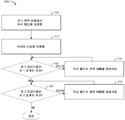
도 6 은 본 개시의 특정 양태들에 따른, 무선 전력 전송을 위한 예시적인 동작들의 플로우차트이다.
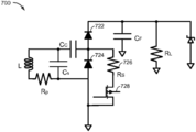
도 7 은 본 개시의 특정 양태들에 따른, 하모닉들을 선택적으로 생성하도록 구성된 수신 회로부의 부분의 개략 다이어그램이다.
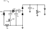
도 8 은 본 개시의 특정 양태들에 따른, 하모닉들을 선택적으로 생성하도록 구성된 수신 회로부의 부분의 개략 다이어그램이다.
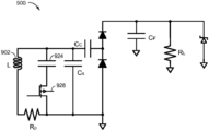
도 9 는 본 개시의 특정 양태들에 따른, 하모닉들을 선택적으로 생성하도록 구성된 수신 회로부의 부분의 개략 다이어그램이다.
도 10 은 본 개시의 특정 양태들에 따른, 하모닉들을 선택적으로 생성하도록 구성된 수신 회로부의 부분의 개략 다이어그램이다.In the following discussion, and in particular with respect to the figures, the details set forth are set forth for purposes of illustrative discussion, and are emphasized to provide examples of the principles of the disclosure and the description of the conceptual aspects. In this regard, no attempt is made to indicate implementation details beyond what is needed for a basic understanding of this disclosure. The discussion that follows, together with the drawings, makes it apparent to those skilled in the art how the embodiments of the present disclosure may be practiced. In the accompanying drawings:
1 is a functional block diagram of a wireless power transmission system, in accordance with an exemplary aspect.
2 is a functional block diagram of a wireless power transmission system, in accordance with an exemplary aspect.
FIG. 3 is a schematic diagram of a portion of the transmitting or receiving circuitry of FIG. 2, including a power transmitting or receiving element, in accordance with an exemplary embodiment.
4 is a schematic diagram of a portion of a receiving circuitry including a rectifier, in accordance with certain aspects of the present disclosure;
5 is a block diagram of a portion of a transmit circuitry, in accordance with certain aspects of the present disclosure.
6 is a flow chart of exemplary operations for wireless power transmission, in accordance with certain aspects of the present disclosure.
Figure 7 is a schematic diagram of a portion of a receiving circuitry configured to selectively generate harmonics, in accordance with certain aspects of the present disclosure.
8 is a schematic diagram of a portion of a receive circuitry configured to selectively generate harmonics, in accordance with certain aspects of the present disclosure.
9 is a schematic diagram of a portion of a receive circuitry configured to selectively generate harmonics, in accordance with certain aspects of the present disclosure.
10 is a schematic diagram of a portion of a receive circuitry configured to selectively generate harmonics, in accordance with certain aspects of the present disclosure;
다음의 도면들 중에 공통인 도면 엘리먼트들은 동일한 참조 부호들을 사용하여 식별될 수도 있다.Drawing elements common to the following Figures may be identified using the same reference numerals.
무선 전력 전송은 전기 필드들, 자기 필드들, 전자기 필드들, 또는 기타 등등과 연관된 임의의 형태의 에너지를 물리적인 전기 컨덕터들의 사용없이 송신기로부터 수신기로 전송하는 것 (예를 들어, 전력이 자유 공간을 통해 전송될 수도 있음) 을 지칭할 수도 있다. 무선 필드 (예를 들어, 자기 필드 또는 전자기 필드) 로의 전력 출력은 전력 전송을 달성하기 위해 "전력 수신 엘리먼트" 에 의해 수신, 캡처 또는 커플링될 수도 있다.Wireless power transmission may involve transferring any form of energy associated with electrical fields, magnetic fields, electromagnetic fields, or the like from a transmitter to a receiver without the use of physical electrical conductors (e.g., Which may be transmitted via a < / RTI > The power output to a wireless field (e.g., a magnetic field or an electromagnetic field) may be received, captured or coupled by a "power receiving element" to achieve power transmission.
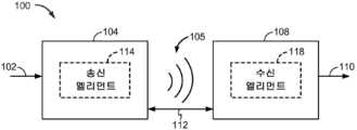
도 1 은 예시적인 양태에 따른, 무선 전력 전송 시스템 (100) 의 기능 블록 다이어그램이다. 입력 전력 (102) 은, 에너지 전송을 수행하기 위한 무선 (예를 들어, 자기 또는 전자기) 필드 (105) 를 생성하기 위해 전력 소스 (이 도면에 도시 안됨) 로부터 송신기 (104) 에 제공될 수도 있다. 수신기 (108) 는, 출력 전력 (110) 에 커플링된 디바이스 (이 도면에 도시 안됨) 에 의한 저장 또는 소비를 위해, 무선 필드 (105) 에 커플링하고 출력 전력 (110) 을 생성할 수도 있다. 송신기 (104) 및 수신기 (108) 는 거리 (112) 만큼 분리될 수도 있다. 송신기 (104) 는 에너지를 수신기 (108) 에 송신/커플링하기 위한 전력 송신 엘리먼트 (114) 를 포함할 수도 있다. 수신기 (108) 는 송신기 (104) 로부터 송신된 에너지를 수신하거나 캡처/커플링하기 위한 전력 수신 엘리먼트 (118) 를 포함할 수도 있다.FIG. 1 is a functional block diagram of a wireless
일 예시적인 양태에 있어서, 송신기 (104) 및 수신기 (108) 는 상호 공진 관계에 따라 구성될 수도 있다. 수신기 (108) 의 공진 주파수와 송신기 (104) 의 공진 주파수가 실질적으로 동일하거나 매우 근접할 경우, 송신기 (104) 와 수신기 (108) 간의 송신 손실들은 감소된다. 그에 따라, 무선 전력 전송은 더 큰 거리들에 걸쳐 제공될 수도 있다. 따라서, 공진 유도성 커플링 기술들은 다양한 거리들에 걸쳐 그리고 다양한 유도성 전력 송신 및 수신 엘리먼트 구성들로 개선된 효율 및 전력 전송을 허용할 수도 있다.In one exemplary aspect, the
특정 양태들에 있어서, 무선 필드 (105) 는 송신기 (104) 의 "근거리장" 에 대응할 수도 있다. 근거리장은, 전력을 전력 송신 엘리먼트 (114) 로부터 멀리 최소로 방사하는 전력 송신 엘리먼트 (114) 내 전류들 및 전하들로부터 기인하는 강한 리액티브 필드들이 존재하는 영역에 대응할 수도 있다. 근거리장은 전력 송신 엘리먼트 (114) 의 대략 일 파장 (또는 그의 분수) 내인 영역에 대응할 수도 있다. 역으로, 원거리장은 전력 송신 엘리먼트 (114) 의 대략 일 파장보다 큰 영역에 대응할 수도 있다.In certain aspects, the
특정 양태들에 있어서, 전자기파에서의 에너지 대부분을 원거리장으로 전파하는 것보다는 무선 필드 (105) 내의 에너지의 대부분을 전력 수신 엘리먼트 (118) 에 커플링시킴으로써, 효율적인 에너지 전송이 발생할 수도 있다.In certain aspects, efficient energy transfer may occur by coupling most of the energy in the
특정 구현들에 있어서, 송신기 (104) 는, 전력 송신 엘리먼트 (114) 의 공진 주파수에 대응하는 주파수를 갖는 시변 자기 (또는 전자기) 필드를 출력할 수도 있다. 수신기 (108) 가 무선 필드 (105) 내에 있을 경우, 시변 자기 (또는 전자기) 필드는 전력 수신 엘리먼트 (118) 에서 전류를 유도할 수도 있다. 상기 설명된 바와 같이, 전력 수신 엘리먼트 (118) 가 전력 송신 엘리먼트 (114) 의 주파수에서 공진하기 위한 공진 회로로서 구성되면, 에너지는 효율적으로 전송될 수도 있다. 전력 수신 엘리먼트 (118) 에서 유도된 교류 (AC) 신호는, 부하를 충전하거나 전력공급하도록 제공될 수도 있는 직류 (DC) 신호를 생성하기 위해 정류될 수도 있다.In certain implementations, the
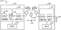
도 2 는 다른 예시적인 양태에 따른, 무선 전력 전송 시스템 (200) 의 기능 블록 다이어그램이다. 시스템 (200) 은 송신기 (204) 및 수신기 (208) 를 포함할 수도 있다. 송신기 (204) (본 명세서에서 전력 전송 유닛, PTU 로서 또한 지칭됨) 는, 오실레이터 (222), 구동기 회로 (224), 및 프론트-엔드 회로 (226) 를 포함할 수도 있는 송신 회로부 (206) 를 포함할 수도 있다. 오실레이터 (222) 는, 주파수 제어 신호 (223) 에 응답하여 조정될 수도 있는 원하는 주파수 (예를 들어, 기본 주파수) 에서 오실레이터 신호 (오실레이팅 신호로서 또한 공지됨) 를 생성하도록 구성될 수도 있다. 오실레이터 (222) 는 오실레이터 신호를 구동기 회로 (224) 에 제공할 수도 있다. 구동기 회로 (224) 는, 예를 들어, 입력 전압 신호 (VD) (225) 에 기초하여 전력 송신 엘리먼트 (214) 의 공진 주파수에서 전력 송신 엘리먼트 (214) 를 구동하도록 구성될 수도 있다. 구동기 회로 (224) 는, 오실레이터 (222) 로부터 구형파를 수신하고 구동 신호 출력으로서 사인파를 출력하도록 구성된 스위칭 증폭기일 수도 있다.FIG. 2 is a functional block diagram of a wireless
프론트-엔드 회로 (226) 는 하모닉들 또는 다른 원치않는 주파수들을 필터링-아웃 (filter out) 하도록 구성된 필터 회로를 포함할 수도 있다. 프론트-엔드 회로 (226) 는 송신기 (204) 의 임피던스를 전력 송신 엘리먼트 (214) 의 임피던스에 매칭하도록 구성된 매칭 회로를 포함할 수도 있다. 하기에서 더 상세히 설명될 바와 같이, 프론트-엔드 회로 (226) 는 전력 송신 엘리먼트 (214) 를 갖는 공진 회로를 생성하기 위한 튜닝 회로를 포함할 수도 있다. 전력 송신 엘리먼트 (214) 를 구동한 결과로서, 전력 송신 엘리먼트 (214) 는, 배터리 (236) 를 충전하거나 또는 그렇지 않으면 부하를 전력공급하기에 충분한 레벨에서 전력을 무선으로 출력하기 위해 무선 필드 (205) 를 생성할 수도 있다.The front-
송신기 (204) 는, 송신 회로부 (206) 에 동작가능하게 커플링되고 그리고 송신 회로부 (206) 의 하나 이상의 양태들을 제어하거나 전력의 전송을 관리하는 것에 관련된 다른 동작들을 달성하도록 구성된 제어기 (240) 를 더 포함할 수도 있다. 제어기 (240) 는 마이크로 제어기 또는 프로세서일 수도 있다. 제어기 (240) 는 주문형 집적 회로 (ASIC) 로서 구현될 수도 있다. 제어기 (240) 는 송신 회로부 (206) 의 각각의 컴포넌트에 동작가능하게 직접 또는 간접적으로 접속될 수도 있다. 제어기 (240) 는 추가로, 송신 회로부 (206) 의 컴포넌트들의 각각으로부터 정보를 수신하고 그리고 수신된 정보에 기초하여 계산들을 수행하도록 구성될 수도 있다. 제어기 (240) 는, 그 컴포넌트의 동작을 조정할 수도 있는 컴포넌트들의 각각에 대한 제어 신호들 (예를 들어, 신호 (223)) 을 생성하도록 구성될 수도 있다. 그에 따라, 제어기 (240) 는, 그에 의해 수행된 동작들의 결과에 기초하여 전력 전송을 조정하거나 관리하도록 구성될 수도 있다. 송신기 (204) 는, 예를 들어, 제어기 (240) 로 하여금 무선 전력 전송의 관리에 관련된 것들과 같은 특정 기능들을 수행하게 하기 위한 명령들과 같은 데이터를 저장하도록 구성된 메모리 (도시 안됨) 를 더 포함할 수도 있다.
수신기 (208) (본 명세서에서 전력 수신 유닛, PRU 로서 또한 지칭됨) 는, 프론트-엔드 회로 (232) 및 정류기 회로 (234) 를 포함할 수도 있는 수신 회로부 (210) 를 포함할 수도 있다. 프론트-엔드 회로 (232) 는 수신 회로부 (210) 의 임피던스를 전력 수신 엘리먼트 (218) 의 임피던스에 매칭하도록 구성된 매칭 회로부를 포함할 수도 있다. 하기에서 설명될 바와 같이, 프론트-엔드 회로 (232) 는 전력 수신 엘리먼트 (218) 를 갖는 공진 회로를 생성하기 위한 튜닝 회로를 더 포함할 수도 있다. 도 2 에 도시된 바와 같이, 정류기 회로 (234) 는 배터리 (236) 를 충전하기 위해 AC 전력 입력으로부터 DC 전력 출력을 생성할 수도 있다. 수신기 (208) 및 송신기 (204) 는 부가적으로, 별도의 통신 채널 (219) (예를 들어, 블루투스, 지그비, 셀룰러 등) 상에서 통신할 수도 있다. 수신기 (208) 및 송신기 (204) 는 대안적으로, 무선 필드 (205) 의 특성들을 이용하여 대역내 시그널링을 통해 통신할 수도 있다.The receiver 208 (also referred to herein as a power receiving unit, also referred to as a PRU) may include a receiving
수신기 (208) 는, 송신기 (204) 에 의해 송신된 및 수신기 (208) 에 의해 수신된 전력의 양이 배터리 (236) 를 충전하기에 적당한지 여부를 결정하도록 구성될 수도 있다. 특정 양태들에 있어서, 송신기 (204) 는, 에너지 전송을 제공하기 위한 직접 필드 커플링 계수 (k) 를 갖는 지배적 비-방사 필드를 생성하도록 구성될 수도 있다. 수신기 (208) 는 무선 필드 (205) 에 직접 커플링할 수도 있고, 출력 또는 수신 회로부 (210) 에 커플링된 배터리 (또는 부하) (236) 에 의한 저장 또는 소비를 위해 출력 전력을 생성할 수도 있다.The
수신기 (208) 는, 무선 전력 수신기 (208) 의 하나 이상의 양태들을 관리하기 위해 상기 설명된 바와 같은 송신 제어기 (240) 와 유사하게 구성된 제어기 (250) 를 더 포함할 수도 있다. 수신기 (208) 는, 예를 들어, 제어기 (250) 로 하여금 무선 전력 전송의 관리에 관련된 것들과 같은 특정 기능들을 수행하게 하기 위한 명령들과 같은 데이터를 저장하도록 구성된 메모리 (도시 안됨) 를 더 포함할 수도 있다.
상기 논의된 바와 같이, 송신기 (204) 및 수신기 (208) 는 거리만큼 분리될 수도 있고, 송신기 (204) 와 수신기 (208) 간의 송신 손실들을 최소화하기 위해 상호 공진 관계에 따라 구성될 수도 있다.As discussed above, the
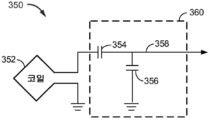
도 3 은 예시적인 양태들에 따른, 도 2 의 송신 회로부 (206) 또는 수신 회로부 (210) 의 부분의 개략 다이어그램이다. 도 3 에 예시된 바와 같이, 송신 또는 수신 회로부 (350) 는 전력 송신 또는 수신 엘리먼트 (352) 및 튜닝 회로 (360) 를 포함할 수도 있다. 전력 송신 또는 수신 엘리먼트 (352) 는 또한 안테나 또는 "루프" 안테나로서 지칭되거나 구성될 수도 있다. 용어 "안테나" 는 일반적으로, 다른 안테나에 커플링하기 위해 에너지를 무선으로 출력 또는 수신할 수도 있는 컴포넌트를 지칭한다. 전력 송신 또는 수신 엘리먼트 (352) 는 또한 "자기" 안테나 또는 유도 코일, 공진기 또는 공진기의 부분으로서 본 명세서에서 지칭되거나 구성될 수도 있다. 전력 송신 또는 수신 엘리먼트 (352) 는 또한, 전력을 무선으로 출력 또는 수신하도록 구성되는 타입의 코일 또는 공진기로서 지칭될 수도 있다. 본 명세서에서 사용된 바와 같이, 전력 송신 또는 수신 엘리먼트 (352) 는, 전력을 무선으로 출력 및/또는 수신하도록 구성되는 타입의 "전력 전송 컴포넌트" 의 일 예이다. 전력 송신 또는 수신 엘리먼트 (352) 는 페라이트 코어 (이 도면에 도시 안됨) 와 같은 물리적 코어 또는 에어 코어를 포함할 수도 있다.FIG. 3 is a schematic diagram of a portion of the transmit
전력 송신 또는 수신 엘리먼트 (352) 가 튜닝 회로 (360) 로의 공진 회로 또는 공진기로서 구성될 경우, 전력 송신 또는 수신 엘리먼트 (352) 의 공진 주파수는 인덕턴스 및 커패시턴스에 기초할 수도 있다. 인덕턴스는, 간단히, 전력 송신 또는 수신 엘리먼트 (352) 를 형성하는 코일 및/또는 다른 인덕터에 의해 생성된 인덕턴스일 수도 있다. 커패시턴스 (예를 들어, 커패시터) 는 원하는 공진 주파수에서 공진 구조를 생성하기 위해 튜닝 회로 (360) 에 의해 제공될 수도 있다. 비한정적인 예로서, 튜닝 회로 (360) 는 커패시터 (354) 및 커패시터 (356) 를 포함할 수도 있으며, 이는 공진 회로를 생성하기 위해 송신 및/또는 수신 회로부 (350) 에 부가될 수도 있다.When the power transmitting or receiving
튜닝 회로 (360) 는, 전력 송신 또는 수신 엘리먼트 (352) 로 공진 회로를 형성하기 위한 다른 컴포넌트들을 포함할 수도 있다. 다른 비한정적인 예로서, 튜닝 회로 (360) 는 회로부 (350) 의 2개의 단자들 사이에 병렬로 배치된 커패시터 (도시 안됨) 를 포함할 수도 있다. 또다른 설계들이 가능하다. 일부 양태들에 있어서, 프론트-엔드 회로 (226) 에서의 튜닝 회로는 프론트-엔드 회로 (232) 에서의 튜닝 회로와 동일한 설계 (예를 들어, 360) 를 가질 수도 있다. 다른 양태들에 있어서, 프론트-엔드 회로 (226) 는 프론트-엔드 회로 (232) 에서와는 상이한 튜닝 회로 설계를 사용할 수도 있다.The
전력 송신 엘리먼트들에 대해, 전력 송신 또는 수신 엘리먼트 (352) 의 공진 주파수에 실질적으로 대응하는 주파수를 갖는 신호 (358) 는 전력 송신 또는 수신 엘리먼트 (352) 에 대한 입력일 수도 있다. 전력 수신 엘리먼트들에 대해, 전력 송신 또는 수신 엘리먼트 (352) 의 공진 주파수에 실질적으로 대응하는 주파수를 갖는 신호 (358) 는 전력 송신 또는 수신 엘리먼트 (352) 에 대한 출력일 수도 있다. 본 명세서에 개시된 양태들이 일반적으로 공진 무선 전력 전송에 관한 것일 수도 있더라도, 당업자는 본 명세서에 개시된 양태들이 무선 전력 전송을 위한 비공진 구현들에서 이용될 수도 있음을 인식할 것이다.For power transmission elements, a
일부 양태들에 있어서, 전력 (예를 들어, 에너지) 이 무선 전력 수신기 (예를 들어, 수신기 (208)) 를 갖는 디바이스 (예를 들어, 의료용 임플란트) 에 의해 무선 전력 송신기 (예를 들어, 송신기 (204)) 로부터 무선으로 수신될 경우, 정확한 양의 전력이 송신기 (204) 로부터 수신기 (208) 로 전송되는 것을 보장하기 위한 전력 제어의 방법이 존재할 수도 있다. 예를 들어, 수신기 (208) 를 갖는 디바이스는 특정 전압 (예를 들어, 4.2 V) 에서 동작/충전하도록 구성될 수도 있다. 하지만, 송신기 (204) 에 의해 고정 강도의 무선 필드 (205) 를 생성하는 것은 수신기 (208) 에서 원하는 전압을 생성하지 않을 수도 있다. 예를 들어, 무선 필드 (205) 의 임의의 주어진 강도로 송신기 (204) 와 수신기 (208) 사이에서 전송되는 전력의 양은 송신기 (204) 와 수신기 (208) 사이의 거리 (및/또는 그 사이의 재료들과 같은 다른 팩터들 등) 에 기초하여 상이할 수도 있다. 이에 따라, 디바이스에 대해 수신기 (208) 에 의해 생성된 전력 (예를 들어, 전압) 은 송신기 (204) 로부터의 무선 필드 (205) 의 동일한 강도에 대한 하나 이상의 팩터들에 기초하여 가변일 수도 있다. 예를 들어, 의료용 임플란트 디바이스는 피하의 다양한 거리들/포지션들에서 그리고 가변하는 조직 타입들 및 두께들로 사람에게 이식될 수도 있다. 이에 따라, 본 명세서에서 논의된 특정 양태들은, 무선 전력 수신기를 갖는 디바이스가 정확한 전력 공급을 수용하는 것을 보장하기 위해 무선 전력 송신기로부터 무선 전력 수신기로 전송된 전력을 제어하기 위한 시스템들 및 방법들에 관련된다.In some aspects, a power (e.g., energy) is transmitted by a device (e.g., a medical implant) having a wireless power receiver (e.g., receiver 208) There may be a method of power control to ensure that an accurate amount of power is transmitted from the
일부 양태들에 있어서, 폐쇄 루프 전력 제어 방식이, 무선으로 전력공급되는 디바이스에서의 전력 (예를 들어, 전압) 이 원하는 전력 (예를 들어, 원하는 전압) 인 것을 보장하기 위해 무선 필드 (205) 의 강도를 조정하도록 채용될 수도 있다. 예를 들어, 일부 양태들에 있어서, 무선 수신기 (208) 는, 정류기 (234) 에서의 전압과 같이 수신기 (208) 에서 수신된 전력의 전력 레벨을 능동적으로 결정하도록 구성될 수도 있다. 예를 들어, 제어기 (250) 는 정류기 (234) 에서의 전압을 모니터링하도록 구성될 수도 있다. 정류기 (234) 에서의 전압이 원하는 전압 레벨의 범위 초과인지 또는 이하인지에 의존하여, (예를 들어, 제어기 (250) 에 의해 제어되는 바와 같은) 무선 수신기 (208) 는 무선 필드 (205) 의 강도가 증가되어야 하는지 또는 감소되어야 하는지를 표시하는 피드백 정보를 (예를 들어, 제어 신호로서) (예를 들어, 무선 필드 (205) 를 사용하여 대역내 시그널링 또는 통신 채널 (219) 을 통해) 무선 송신기 (204) 에 송신할 수도 있다. 정류기 (234) 에서의 전압이 원하는 전압 레벨의 범위 내에 있으면 어떠한 제어 신호도 전송되지 않을 수도 있다. 무선 송신기 (204) 는 제어 신호를 수신하고, 이에 따라, (예를 들어, 제어기 (240) 로부터의 제어에 의해) 무선 필드 (205) 의 강도를 조정할 수도 있다.In some aspects, a closed loop power control scheme may be used to control the
일부 양태들에 있어서, 수신기 (208) 에서의 전력 레벨들은 매우 낮을 수도 있으며, 따라서, 피드백 정보를 송신하기 위한 더 높은 전력 기술들 (예를 들어, 통신 채널 (219) 또는 대역내 시그널링을 통한 더 높은 전력 통신) 이 가능하지 않을 수도 있다. 특히, 수신기 (208) 를 갖는 디바이스는 송신기 (204) 로 피드백 정보를 능동적으로 송신할 수 없을 수도 있어서, 송신기 (204) 는 충전되는 디바이스에서의 전압에 관한 정보를 갖지 않으며, 디바이스가 현재 기법들을 사용하여 정확한 전압에서 동작하고 있음을 보장하기 위해 무선 필드 (205) 의 강도를 조정하지 못할 수 있다. 예를 들어, 디바이스에서의 배터리가 완전히 방전되면, 전력이 디바이스에서의 무선 수신기 (208) 에 의해 무선 전력 송신기 (204) 로부터 처음에 수신된 때와, 디바이스가 시동되고 송신기 (204) 로 피드백 정보를 송신하기 위해 (예를 들어, 무선기기를 통한) 통신 채널 (219) 또는 (예를 들어, 전력을 요구하는 제어기 (250) 에 의해 제어되는 바와 같은) 대역내 시그널링을 사용할 수 있을 때와의 사이의 시간 지연 (예를 들어, 10 s) 이 존재할 수도 있다. 일부 경우들에 있어서, 디바이스는 피드백 정보를 송신하기 위한 수단 (예를 들어, 무선기기) 을 갖지 않을 수도 있다.In some aspects, the power levels at the
이에 따라, 본 개시의 특정 양태들은 무선 전력 송신기의 전력 레벨을 제어하기 위하여 무선 전력 전송을 위한 피드백 메커니즘들에 관한 것이다. 특히, 논의된 바와 같이, 수신기 (208) 는 AC 전력 입력으로부터 DC 전력 출력을 생성하기 위해 정류기 (234) 를 포함한다. 본 개시의 특정 양태들은 수신기 (208) 에서의 전압 레벨에 관한 피드백 정보를 제공하도록 설계된 정류기에 관한 것이다. 특히, 특정 양태들은, 정류 동안 하모닉들을 생성하고 그러한 하모닉들을 사용하여 송신기 (204) 와 통신하도록 구성된 수신기 (208) 에 관한 것이다. 예를 들어, 수신기 (208) 는, 수신기 (208) 에서의 충분한 전력 또는 심지어 임의의 다른 정보 (예를 들어, 수신기 (208) 의 다른 스테이터스 정보) 가 존재함을 표시하는 특정 하모닉들을 생성할 수도 있다. 특정 양태들에 있어서, 송신기 (204) 는 그러한 하모닉들을 (예를 들어, 송신 엘리먼트 (214) 와 같은 안테나를 통해) 검출할 수도 있다. 특정 양태들에 있어서, 하모닉들의 검출은, 무선 전력을 수신하도록 구성되고 수신할 수 있는 디바이스 (예를 들어, 수신기 (208)) 가 존재하고 무선 전력을 흡수하고 있음을 송신기 (204) 에 표시할 수도 있다. 특정 양태들에 있어서, 하모닉들의 검출은 논의된 바와 같은 다른 정보를 표시할 수도 있다.Accordingly, certain aspects of the disclosure are directed to feedback mechanisms for wireless power transmission to control the power level of a wireless power transmitter. In particular, as discussed, the
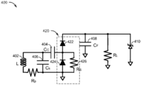
도 4 는 본 개시의 특정 양태들에 따른, 정류기를 포함한 수신 회로부 (400) 의 부분의 개략 다이어그램이다. 수신 회로부 (400) 는 수신기 (208) 의 부분에 대응할 수도 있다. 도시된 바와 같이, 수신 회로부 (400) 는 수신 안테나 (예를 들어, 인덕터, 코일, 수신 엘리먼트 (352) 등) (402) 를 포함한다. 추가로, 수신 회로부 (400) 는 커플링 커패시터 (CC) (404) 및 션트 공진 커패시터 (CS) (406) (예를 들어, 300 pF) 를 포함한다. CC (404) 는 큰값의 (예를 들어, 260 pF) 커패시터일 수도 있으며, AC 전력을 정류기 (420) 에 커플링하도록 구성될 수도 있다. 커패시터들 (404 및 406) 은 원하는 공진 주파수에서 공진 구조를 생성하기 위해 제공될 수도 있다.4 is a schematic diagram of a portion of receive
수신 회로부 (400) 는, 전송된 전력을 필터링/평활화하도록 구성될 수도 있는 필터 커패시터 (Cf) (408) (예를 들어, .01 μF) 를 더 포함한다. 추가로, 수신 회로부 (400) 에 의해 전력공급된 부하 (예를 들어, 배터리, 임플란트 디바이스 등) 의 등가 저항 (RL) (예를 들어, 1 kΩ) 이 도시된다. 특정 양태들에 있어서, 수신 회로부 (400) 는, 전압 클램프로서 작동하도록 구성되는 옵션적인 다이오드 (410) (예를 들어, 제너 다이오드) 를 포함한다. 추가로, 커패시터들 및 안테나의 기생 저항 (RP) (예를 들어, 1 Ω) 이 도시된다.The receiving
정류기 (420) 는 직렬로 커플링된 제 1 다이오드 (422) 및 제 2 다이오드 (424) 를 포함한다. 추가로, 정류기 (420) 는 제 2 다이오드 (424) 에 병렬로 커플링된 저항기 (RS) (426) (예를 들어, 100 kΩ 과 같은 높은 값의 저항기) 를 포함하고, RS (426) 의 제 1 단자는 제 2 다이오드 (424) 의 제 1 단자에 커플링되고, RS (426) 의 제 2 단자는 제 2 다이오드 (424) 의 제 2 단자에 커플링된다. 특정 양태들에 있어서, 제 1 다이오드 (422) 및 제 2 다이오드 (424) 는 전압 더블러 정류기로서 또는 그 부분으로서 작동하도록 구성된다.The
정류기 (420) 의 특성들은 수신 회로부 (400) 에서의 전압 레벨 (예를 들어, 수신 회로부 (400) 에 접속된 부하에서의 전압) 에 관한 피드백 정보로서 사용될 수도 있다. 예를 들어, 무선 전력 송신기 (예를 들어, 송신기 (204)) 로부터 안테나 (402) 에 의해 수신된 전력이 발생함에 따라, 제 1 다이오드 (422) 및 제 2 다이오드 (424) 의 비선형 특성들은 제 1 다이오드 (422) 및 제 2 다이오드 (424) 로 하여금 전압 레벨로 변화하는 하모닉들을 생성하게 한다. 제 1 임계치 (예를 들어, .5 V) 이하의 안테나 (402) 에 의해 수신된 전력 레벨들에서, RS (426) 가 제 1 다이오드 (422) 와 제 2 다이오드 (424) 사이의 노드에서의 전압을 낮게 유지함에 따라 제 1 다이오드 (422) 또는 제 2 다이오드 (424) 중 어느 것도 도전되지 않는다. 이에 따라, 수신 회로부 (400) 의 부하에서 실질적으로 어떠한 전압도 존재하지 않는다.The characteristics of the
무선 전력 송신기 (예를 들어, 송신기 (204)) 로부터 안테나 (402) 에 의해 수신된 전력이 제 1 임계치 초과이지만 제 2 임계치 (예를 들어, RL 상의 .5 V 초과의 전압) 이하로 발생함에 따라, 제 2 다이오드 (424) 가 도전되기 시작한다. 특히, 제 2 다이오드 (424) 와 병렬인 RS (426) 는 제 2 다이오드 (424) 로 하여금 제 1 다이오드 (422) 보다 낮은 전력 레벨들에서 도전되게 한다. 제 2 다이오드 (424) 가 도전됨에 따라, 수신된 전력 신호 (예를 들어, 특정 기본 주파수에서 수신됨) 의 제 2 하모닉들이 제 2 다이오드 (424) 에 의해 생성되고 안테나 (402) 를 통해 다시 방사된다. 제 2 하모닉들의 그러한 생성은 제 2 다이오드 (424) 의 특성들에 기초하고 능동 회로부에 의해 별도로 생성되지 않음을 유의해야 한다. 안테나 (402) 로부터 다시 방사된 그러한 제 2 하모닉들은, 본 명세서에서 추가로 논의되는 바와 같이 무선 전력 송신기 (예를 들어, 송신기 (204)) 에 의해 검출가능할 수도 있다. 오직 제 2 다이오드 (424) 만이 도전되는 전력 레벨들에서, 수신 회로부 (400) 의 부하에서의 전압 레벨은 원하는 전압 레벨 이하일 수도 있다.If the power received by
추가로, 무선 전력 송신기 (예를 들어, 송신기 (204)) 로부터 안테나 (402) 에 의해 수신된 전력이 제 2 임계치 초과로 발생함에 따라, 제 2 다이오드 (424) 에 부가하여 제 1 다이오드 (422) 가 도전되기 시작한다. 특히, 이들 더 높은 전력 레벨들에서, 회로에 대한 RS (426) 의 영향은, 제 1 다이오드와 제 2 다이오드 (424) 사이의 노드에서의 전압이 제 1 다이오드 (422) 및 제 2 다이오드 (424) 의 클램핑 액션에 의해 설정될 때 최소가 된다. 제 1 다이오드 (422) 및 제 2 다이오드 (424) 는 수신된 전력 신호의 제 3 하모닉들을 생성한다. 제 3 하모닉들은 안테나 (402) 를 통해 다시 방사된다. 제 3 하모닉들의 그러한 생성은 제 1 다이오드 (422) 및 제 2 다이오드 (424) 의 특성들에 기초하고 능동 회로부에 의해 별도로 생성되지 않음을 유의해야 한다. 그러한 제 3 하모닉들은, 본 명세서에서 추가로 논의되는 바와 같이 무선 전력 송신기 (예를 들어, 송신기 (204)) 에 의해 검출가능할 수도 있다. 제 1 다이오드 (422) 및 제 2 다이오드 (424) 가 도전되는 전력 레벨들에서, 수신 회로부 (400) 의 부하에서의 전압 레벨은 원하는 전압 레벨이거나 그 근처일 수도 있다.Additionally, as the power received by the
무선 전력 송신기, 예를 들어, 송신기 (204) 는 안테나 (402) 로부터 방사된 (예를 들어, 반사된) 제 2 및 제 3 하모닉들을 검출하고, 그 신호들에 기초하여, 무선 전력 송신기에 의해 방출된 충전 필드의 전력을 제어하도록 구성될 수도 있다. 특정 양태들에 있어서, 무선 전력 송신기는 충전 필드의 전력을 제어하기 위해 제 2 및 제 3 하모닉들의 각각의 레벨 또는 제 2 및 제 3 하모닉들의 비율을 활용할 수도 있다.A wireless power transmitter, e.g.,
특정 양태들에 있어서, 송신기 (204) 는, 수신기 (208) 에 송신하기 위한 클린 (최소의 2차 또는 3차 하모닉들) 무선 필드 (205) 를 생성하도록 구성될 수도 있다. 예를 들어, 프론트-엔드 회로 (226) 는, 무선 필드 (205) 를 생성하도록 활용된 신호로부터 2차 및 3차 하모닉들을 필터링-아웃하도록 구성된 필터 회로를 포함할 수도 있다. 그러한 제 2 및 제 3 하모닉들을 필터링-아웃하는 것은, 송신기 (204) 로부터의 그러한 제 2 및 제 3 하모닉들이 수신기 (208) 에 의해 생성된 제 2 및 제 3 하모닉들로 오해받는 것을 방지하도록 도울 수도 있다. 무선 필드 (205) 의 전력 레벨이 증가하고 제 1 다이오드 (422) 및/또는 제 2 다이오드 (424) 가 도전되기 시작함에 따라, 송신기 (204) 는 수신기 (208) 로부터 방사된 하모닉들을 수신할 수도 있다. 송신기 (204) 는 방사된 하모닉들을 수신하기 위해 무선 필드 (205) 를 생성하도록 사용된 바와 동일한 전력 송신 엘리먼트 (214) 를 활용할 수도 있거나, 또는 상이한 엘리먼트 (예를 들어, 안테나, 코일 등) 를 사용할 수도 있다. 방사된 하모닉들은, 무선 필드 (205) 와 같이 다른 신호들을 포함할 수도 있는 수신기 (208) 에 의해 생성된 무선 필드의 부분으로서 수신될 수도 있다. 송신기 (204) 는, 본 명세서에서 논의된 바와 같이 수신된 하모닉들에 기초하여 무선 전력 송신기 (204) 에 의해 방출된 무선 필드 (205) 의 전력을 제어할 수도 있다.The
도 5 는 본 개시의 특정 양태들에 따른, 송신 회로부 (500) 의 부분의 블록 다이어그램이다. 송신 회로부 (500) 는 송신기 (204) 의 부분에 대응할 수도 있다. 송신 회로부 (500) 는 수신기 (208) 로부터 방사된 하모닉들을 수신하도록 활용될 수도 있다. 도시된 바와 같이, 송신기 회로부 (500) 는 안테나 (예를 들어, 전력 송신 엘리먼트 (214), 별도의 안테나, 코일 등) (502) 를 포함한다. 안테나 (502) 로부터의 수신된 신호는 증폭기 (503) 에 의해 증폭되고, 각각 제 2 및 제 3 하모닉들을 위해 선택하는 2개의 별도의 필터들 (예를 들어, 대역 필터들) 을 통해 분할 및 통과될 수도 있다. 특히, 수신된 신호는, 제 2 하모닉들에 대응하는 신호에서의 주파수들을 통과하도록 대역 통과 필터를 포함할 수도 있는 도시된 바와 같은 제 1 필터 (504) 로 통과될 수도 있다. 부가적으로, 수신된 신호는, 제 3 하모닉들에 대응하는 신호에서의 주파수들을 통과하도록 대역 통과 필터를 포함할 수도 있는 도시된 바와 같은 제 2 필터 (506) 로 통과될 수도 있다.5 is a block diagram of a portion of transmit
그 후, 제 1 필터 (504) 및 제 2 필터 (506) 의 각각의 출력은, 수신된 제 2 하모닉들 및 제 3 하모닉들의 상대적 강도를 검출하기 위해 하나 이상의 신호 프로세서들 (예를 들어, 신호 검출기들) (508) 에 전송될 수도 있다. 특정 양태들에 있어서, 별도의 신호 프로세서들 (508) 이 제 2 하모닉들 및 제 3 하모닉들의 각각을 검출하기 위해 사용될 수도 있다. 특정 양태들에 있어서, 단일의 신호 프로세서 (508) 가 제 2 하모닉들 및 제 3 하모닉들 양자를 검출하도록 구성될 수도 있다. (예를 들어, 하나 이상의 임계치들, 절대 표시자들, 강도에 비례하는 전압 출력 등에 대한) 강도의 표시들이, 무선 필드 (205) 의 전력을 조정하기 위해 신호 프로세서 (508) 로부터 제어기 (240) (또는 다른 프로세서) 로 전송될 수도 있다. 특정 양태들에 있어서, 신호 프로세서 (508) 및 제어기 (240) 는 단일의 칩 또는 별도의 칩들 상에서 구현될 수도 있다.Each output of the
제어기 (240) 는, 수신기 (208) 로부터 수신된 제 2 및 제 3 하모닉들의 강도의 표시들에 기초하여 무선 필드 (205) 의 전력을 제어할 수도 있다. 특히, 제어기 (240) 는, 특정 양태들에 있어서, 수신된 제 2 하모닉들의 강도가 제 1 임계치를 초과하고 수신된 제 3 하모닉들의 강도가 제 2 임계치를 초과할 때까지 (예를 들어, 송신기 (204) 와 수신기 (208) 사이의 초기 커플링 시에) 디바이스를 처음에 전력공급할 경우 무선 필드 (205) 의 전력을 증분적으로 증가시키도록 구성될 수도 있다. 그 후, 제어기 (240) 는 무선 필드 (205) 의 강도를 유지하거나, 또는 수신기 (208) 가 완전히 전력공급될 때까지 무선 필드 (205) 의 강도를 기지의 양만큼 증가시킬 수도 있다.The
도 6 은 본 개시의 특정 양태들에 따른, 무선 전력 전송을 위한 예시적인 동작들 (600) 의 플로우차트이다.6 is a flow chart of
605 에서, 송신기 (204) 는 수신기 (208) 로 전력을 전송하기 위해 초기 전력 레벨 (예를 들어, 최저 전력 레벨) 에서 무선 필드 (205) 를 생성할 수도 있다. 특정 양태들에 있어서, 무선 필드 (205) 를 생성하기 전에, 송신기 (204) 는, 생성될 무선 필드 (205) 의 하모닉들에서 하모닉 레벨들 (예를 들어, 제 2 및 제 3 하모닉들) 을 측정할 수도 있다. 일부 양태들에 있어서, 무선 전력 수신기의 검출, 무선 필드 (205) 의 전력 레벨의 조정 등을 위한 제 2 하모닉들 및 제 3 하모닉들에 대한 임계치들은 측정된 하모닉 레벨들에 기초하여 조정될 수도 있다 (예를 들어, 측정된 하모닉 레벨들을 기선으로서 사용하고 특정 임계치만큼의 증가를 찾음). 610 에서, 송신기 (204) 는, 수신기 (208) 로부터의 방사된 하모닉들을 포함할 수도 있는 수신된 신호를 측정할 수도 있다. 특정 양태들에 있어서, 송신기 (204) 는, 수신기 (208) 로부터의 방사된 하모닉들을 측정하는 동안 무선 필드 (205) 를 생성하는 것을 유지할 수도 있다. 특정 양태들에 있어서, 송신기 (204) 는, 수신기 (208) 로부터의 방사된 하모닉들을 측정하는 동안 일시적으로 (예를 들어, 구동기 (224) 를 파워-다운함으로써) 무선 필드 (205) 를 생성하는 것을 중지하고, 그 후, 무선 필드 (205) 를 생성하는 것으로 리턴할 수도 있다. 615 에서, 송신기 (204) 는 수신된 신호에서의 2차 하모닉들이 제 1 임계치를 초과하는지를 결정한다. 2차 하모닉들이 제 1 임계치를 초과하지 않으면, 620 에서, 송신기 (204) 는 무선 필드 (205) 의 전력 레벨 업을 증분시키고 615 로 리턴한다.At 605, the
2차 하모닉들이 제 1 임계치를 초과하면, 625 에서, 송신기 (204) 는 수신된 신호 상의 3차 하모닉들이 제 2 임계치를 초과하는지를 결정한다. 3차 하모닉들이 제 2 임계치를 초과하지 않으면, 630 에서, 송신기 (204) 는 무선 필드 (205) 의 전력 레벨 업을 증분시키고 625 로 리턴한다.If the second harmonics exceed the first threshold, then at 625, the
3차 하모닉들이 제 2 임계치를 초과하면, 동작들 (600) 은 종료할 수도 있다. 송신기 (204) 는 무선 필드 (205) 의 강도를 유지하거나, 또는 무선 필드 (205) 의 강도를 기지의 양만큼 증가시킬 수도 있다. 특히, 일단 3차 하모닉들이 제 2 임계치를 초과하면, 수신기 (208) 의 다이오드들은 도전되고 있고, 수신기 (208) 를 갖는 디바이스가 파워-업하기 위해 충분한 전력이 수신기 (208) 에서 수신되고 있다. 송신기 (204) 및 수신기 (208) 의 추가의 제어가 피드백을 위한 기법들 및 다른 수단들에 의해 달성될 수도 있다.If tertiary harmonics exceed the second threshold, then
일부 양태들에 있어서, 도 4 에 관하여 논의된 수신 회로부 (400) 는 수동 회로부를 사용하여 하모닉들을 생성하고, 임의의 능동 회로부들 (예를 들어, 스위치들) 이 하모닉들을 생성할 것을 요구하지 않도록 구성될 수도 있다. 이에 따라, 수신 회로부 (400) 는, 논의된 바와 같이, 하모닉들을 생성하도록 그러한 능동 회로부를 제어하기 위한 추가적인 전력을 요구하지 않을 수도 있고, 매우 낮은 전력 레벨들에서 작동할 수 있다.In some aspects, the receiving
일부 다른 양태들에 있어서, 수신기 (예를 들어, 수신기 (208)) 에서의 수신 회로부는, 송신기 (204) 와 통신하기 위해 수신기 (208) 에서의 하모닉들을 선택적으로 생성하기 위한 일부 능동 회로부를 갖도록 설계될 수도 있다. 송신기 (204) 는 수신기 (208) 에 의해 생성된 하모닉들을 (예를 들어, 송신 회로부 (500) 를 활용하여) 검출하고, 수신된 하모닉들을, 통신된 정보를 표시하는 것으로서 해석할 수도 있다. 특히, 일부 능동 회로부를 활용함으로써, 하모닉들이 생성되는 때 및 방법이 수신기 (208) 에 의해 능동적으로 제어될 수 있어서, 거의 임의의 정보가 그러한 하모닉들에 의해 표시될 수 있다. 예를 들어, 일부 양태들에 있어서, 하모닉들의 단순한 존재 여부는 정보의 단일 비트 (예를 들어, 수신기 (208) 가 충분한 전력을 갖는지 여부, 수신기 (208) 가 통상적으로 기능하고 있는지 여부 등) 를 표시할 수 있다. 추가로. 일부 양태들에 있어서, 하모닉들은 추가 정보 (예를 들어, 상이한 변조 또는 변동에 대응하는 정보의 비트들) 를 표시하도록 수정 (예를 들어, 변조 또는 변경) 될 수도 있다. 예를 들어, 일부 양태들에 있어서, 하모닉들은 수동 다이오드 정류 경로를 조정하는 것, 또는 정류 경로에서의 컴포넌트들 (예를 들어, 스위치들, 저항기들 등) 을 통한 정류에 대한 다른 수정에 의해 수정될 수도 있다. 예를 들어, 직렬 저항을 (예컨대, 스위치를 선택적으로 개방 및 폐쇄함으로써) 스위칭하는 것, 부하, 토폴로지 변화들, 공진기의 재-튜닝 등은 모두, 생성된 하모닉들을 수정하도록 수행될 수도 있다. 일부 양태들에 있어서, 하모닉들은, 수신기 (208) 의 능동 정류기의 하나 이상의 스위치들을 (예컨대, 스위치를 선택적으로 개방 및 폐쇄함으로써) 스위칭하는 것에 의해 하모닉들을 변조함으로써 수정될 수도 있다. 하모닉들은, 수신기 (208) 에서의 전력 레벨을 송신기 (204) 에 시그널링하기 위해 능동 정류기에 의해 생성된 DC 전류의 전력 레벨에 기초하여 변조될 수도 있다. 본 명세서에서 설명된 기법들은, 일부 양태들에 있어서, 정보를 통신하기 위해 다른 능동 회로 기법들보다 여전히 더 낮은 전력인 동안 수신기 (208) 와 송신기 (204) 사이에서 정보를 통신하도록, 하모닉들을 선택적으로 생성 및/또는 수정하기 위해 저전력 소비 기법들을 활용할 수도 있다.In some other aspects, the receiving circuitry in the receiver (e.g., receiver 208) may be configured to have some active circuitry for selectively generating harmonics at the
일부 양태들에 있어서, 수신기 (208) 에 의해 생성된 하모닉들은, 송신기 (204) 가 무선 필드 (205) 를 생성할 경우에 홀수 하모닉들을 또한 생성할 수도 있기 때문에, 수신기 (208) 로부터 하모닉들을 수신하기 위해 송신기 (204) 에서 낮은 신호 대 노이즈 비를 회피하도록 홀수 하모닉들과는 대조적으로 짝수 하모닉들 (예를 들어, 2차, 4차 등) 일 수도 있다. 이에 따라, 특정 양태들에 있어서, 수신기 (208) 는, 그러한 짝수 하모닉들을 생성하기 위해 비선형 컴포넌트들 (예를 들어, 역 바이어싱된 다이오드 접합 (예를 들어, 다이오드 또는 FET) 과 같은 전압의 함수로서의 커패시턴스를 갖는 커패시터) 을 활용할 수도 있다.In some aspects, the harmonics generated by the
도 7 은 본 개시의 특정 양태들에 따른, 하모닉들을 선택적으로 생성하도록 구성된 수신 회로부 (700) 의 부분의 개략 다이어그램이다. 수신 회로부 (700) 는 수신기 (208) 의 부분에 대응할 수도 있다. 특히, 수신 회로부 (700) 는, 도시된 바와 같이, 도 4 의 수신 회로부 (400) 와 거의 동일한 컴포넌트들을 가질 수도 있다. 하지만, 수신 회로부 (700) 는, 제 2 다이오드 (724) 와 병렬인 저항기 (726) 를 (스위치 (728) 를 선택적으로 개방 및 폐쇄함으로써) 선택적으로 커플링하도록 구성된 스위치 (예를 들어, 트랜지스터) (728) 를 더 포함할 수도 있다. 이에 따라, 수신 회로부 (700) 는, 저항기 (726) 가 제 2 다이오드 (724) 와 병렬로 커플링되는지 여부에 기초하여 하모닉들 (예를 들어, 제 2 및 제 3 하모닉들) 을 선택적으로 생성하도록 구성될 수도 있다. 예를 들어, 일부 양태들에 있어서, 하모닉들은 저항기 (726) 가 제 2 다이오드 (724) 와 병렬로 커플링될 경우에 생성될 수도 있으며, 하모닉들은 저항기 (726) 가 제 2 다이오드 (724) 와 병렬로 커플링되지 않을 경우에 생성되지 않을 수도 있다. 스위치 (728) 는 제어기 (250) 와 같은 제어기에 의해 제어될 수도 있다.FIG. 7 is a schematic diagram of a portion of receive
도 8 은 본 개시의 특정 양태들에 따른, 하모닉들을 선택적으로 생성하도록 구성된 수신 회로부 (800) 의 다른 부분의 개략 다이어그램이다. 수신 회로부 (800) 는 수신기 (208) 의 부분에 대응할 수도 있다. 특히, 수신 회로부 (800) 는, 도시된 바와 같이, 도 4 의 수신 회로부 (400) 와 거의 동일한 컴포넌트들을 가질 수도 있다. 하지만, 수신 회로부 (800) 는 수신 회로부 (400) 의 저항기 (426) 를 포함하지 않을 수도 있다. 추가로, 수신 회로부 (800) 는 부가적으로, 수신 안테나 (802) 와 병렬로 선택적으로 커플링된 커패시터 (824) 를 포함할 수도 있다. 특히, 스위치 (예를 들어, 트랜지스터) (828) 는 커패시터 (824) 와 직렬로 커플링되고, 그리고 수신 안테나 (802) 와 병렬인 커패시터 (824) 를 (스위치 (828) 를 선택적으로 개방 및 폐쇄함으로써) 선택적으로 커플링하도록 구성될 수도 있다. 추가로, 수신 회로부 (800) 는 부가적으로, 안테나 (802) 와 직렬로 커플링된 인덕터 (826) 를 포함할 수도 있으며, 여기서, 커패시터 (824) 의 커플링 포인트는 수신 안테나 (802) 와 인덕터 (826) 사이이다. 커패시터 (824) 및 인덕터 (826) 는, 수신 회로부 (800) 로부터 하모닉들을 차단하거나 통과시킬 수도 있는 전자기 간섭 (EMI) 필터들을 작동하도록 구성될 수도 있다. 특히, 안테나 (802) 와 병렬인 커패시터 (824) 를 선택적으로 커플링 또는 디커플링하는 것은 EMI 필터로서의 효과를 끊거나 수정할 수도 있고, 따라서, 하모닉들을 차단하거나 통과시킬 수도 있다. 예를 들어, 커패시터 (824) 가 안테나 (802) 와 병렬로 커플링되면, 인덕터 (826) 및 커패시터 (824) 는 하모닉들이 생성되는 것을 차단할 수도 있다. 하지만, 커패시터 (824) 가 안테나 (802) 와 병렬로 커플링되지 않으면, 수신 회로부 (800) 는 하모닉들을 생성할 수도 있다. 스위치 (828) 는 제어기 (250) 와 같은 제어기에 의해 제어될 수도 있다.FIG. 8 is a schematic diagram of another portion of receive
도 9 은 본 개시의 특정 양태들에 따른, 하모닉들을 선택적으로 생성하도록 구성된 수신 회로부 (900) 의 다른 부분의 개략 다이어그램이다. 수신 회로부 (900) 는 수신기 (208) 의 부분에 대응할 수도 있다. 특히, 수신 회로부 (900) 는, 도시된 바와 같이, 도 4 의 수신 회로부 (400) 와 거의 동일한 컴포넌트들을 가질 수도 있다. 하지만, 수신 회로부 (900) 는 수신 회로부 (400) 의 저항기 (426) 를 포함하지 않을 수도 있다. 추가로, 수신 회로부 (900) 는 부가적으로, 수신 안테나 (902) 와 병렬로 커플링된 커패시터 (924) 를 포함할 수도 있다. 일부 양태들에 있어서, 스위치 (예를 들어, 트랜지스터) (928) 는 커패시터 (924) 와 직렬로 커플링되고, 그리고 수신 안테나 (902) 와 병렬인 커패시터 (924) 를 (스위치 (928) 를 선택적으로 개방 및 폐쇄함으로써) 선택적으로 커플링하도록 구성될 수도 있다. 커패시터 (924) 는 비선형 커패시턴스를 가질 수도 있다 (예를 들어, 커패시터 (924) 는 트랜스캡 가변 커패시터, 버랙터/다이오드, FET 등 중 하나일 수도 있음). 이에 따라, 커패시터 (924) 가 안테나 (902) 와 병렬로 커플링되면, 수신 회로부 (900) 는 짝수 하모닉들을 생성할 수도 있다. 하지만, 커패시터 (924) 가 안테나 (902) 와 병렬로 커플링되지 않으면, 수신 회로부 (900) 는 하모닉들을 생성하지 않을 수도 있다. 스위치 (928) 는 제어기 (250) 와 같은 제어기에 의해 제어될 수도 있다. 다른 양태에 있어서, 스위치 (928) 를 포함하는 수신 회로부 (900) 대신, 커패시터 (924) 의 커패시턴스는 하모닉들을 선택적으로 생성하기 위해 조정될 수도 있다 (예를 들어, 커패시터 (924) 는 가변 커패시터를 포함할 수도 있음). 커패시터 (924) 의 커패시턴스는 제어기 (250) 와 같은 제어기에 의해 제어될 수도 있다.FIG. 9 is a schematic diagram of another portion of receive
도 10 은 본 개시의 특정 양태들에 따른, 하모닉들을 선택적으로 생성하도록 구성된 수신 회로부 (1000) 의 다른 부분의 개략 다이어그램이다. 수신 회로부 (1000) 는 수신기 (208) 의 부분에 대응할 수도 있다. 특히, 수신 회로부 (1000) 는, 도시된 바와 같이, 도 4 의 수신 회로부 (400) 와 거의 동일한 컴포넌트들을 가질 수도 있다. 하지만, 수신 회로부 (1000) 는 수신 회로부 (400) 의 저항기 (426) 를 포함하지 않을 수도 있다. 추가로, 수신 회로부 (1000) 는 수동 정류기를 형성하는 제 1 다이오드 (422) 및 제 2 다이오드 (424) 를 포함하지 않을 수도 있지만, 대신, 트랜지스터들 (1022 및 1024) 을 사용하여 도시된 바와 같은 능동 정류기를 포함할 수도 있다. 일부 양태들에 있어서, 트랜지스터들 (1022 및 1024) 의 스위치 타이밍 (개방 및 폐쇄) 은, 송신기 (204) 로부터의 수신된 전력의 대부분을 여전히 정류하는 동안 하모닉들을 변조하도록 수정될 수 있다. 일부 다른 양태들에 있어서, 트랜지스터들 (1022 및 1024) 은 정류를 선택적으로 인에이블 및 디스에이블하도록 선택적으로 인에이블되고 디스에이블될 수도 있다. 정류가 인에이블될 경우, 하모닉들이 생성될 수도 있다. 정류가 디스에이블될 경우, 하모닉들은 생성되지 않을 수도 있다. 트랜지스터들 (1022 및 1024) 은 제어기 (250) 와 같은 제어기에 의해 제어될 수도 있다.FIG. 10 is a schematic diagram of another portion of receiving
송신기 (204) 는 회로부 (700-100) 중 임의의 회로부에 의해 생성된 그러한 하모닉들을 수신하고 그리고 수신된 하모닉들에 기초하여 액션을 수행 (예를 들어, 무선 필드 (205) 의 강도를 조정) 하도록 구성될 수도 있다. 예를 들어, 상기 논의된 바와 같이, 수신기 (208) 의 제어기 (250) 는, 송신기 (204) 가 액션을 수행하도록 활용할 수도 있는 정보를 송신기 (204) 에 통신하기 위해 하모닉들을 선택적으로 생성하도록 구성될 수도 있다.The
상기 설명된 방법들의 다양한 동작들은 대응하는 기능들을 수행 가능한 임의의 적합한 수단에 의해 수행될 수도 있다. 그 수단은 회로, 주문형 집적 회로 (ASIC), 또는 프로세서를 포함하지만 이에 한정되지 않는 다양한 하드웨어 및/또는 소프트웨어 컴포넌트(들) 및/또는 모듈(들)을 포함할 수도 있다. 일반적으로, 도면들에 예시된 동작들이 존재하는 경우, 그 동작들은 유사한 넘버링을 갖는 대응하는 상대의 수단-플러스-기능 컴포넌트들을 가질 수도 있다.The various operations of the above-described methods may be performed by any suitable means capable of performing the corresponding functions. The means may include various hardware and / or software component (s) and / or module (s), including, but not limited to, circuitry, an application specific integrated circuit (ASIC) In general, when the operations illustrated in the Figures are present, they may have corresponding relative means-plus-function components with similar numbering.
본 명세서에서 사용된 바와 같이, 용어 "결정하는 것" 은 매우 다양한 액션들을 포괄한다. 예를 들어, "결정하는 것" 은 계산하는 것, 연산하는 것, 프로세싱하는 것, 도출하는 것, 조사하는 것, 검색하는 것 (예를 들어, 표, 데이터베이스, 또는 다른 데이터 구조에서 검색하는 것), 확인하는 것 등을 포함할 수도 있다. 또한, "결정하는 것" 은 수신하는 것 (예를 들어, 정보를 수신하는 것), 액세스하는 것 (예를 들어, 메모리 내 데이터에 액세스하는 것) 등을 포함할 수도 있다. 또한, "결정하는 것" 은 해결하는 것, 선택하는 것, 선출하는 것, 확립하는 것 등을 포함할 수도 있다.As used herein, the term " determining "encompasses a wide variety of actions. For example, "determining" may include calculating, computing, processing, deriving, investigating, searching (e.g., searching in a table, database, ), Confirmation, and so on. In addition, "determining" may include receiving (e.g., receiving information), accessing (e.g., accessing in-memory data), and the like. In addition, "determining" may include resolving, selecting, electing, establishing, and the like.
본 명세서에서 사용된 바와 같이, 아이템들의 리스트 "중 적어도 하나" 를 지칭하는 어구는 단일 멤버들을 포함하여 그 아이템들의 임의의 조합을 지칭한다. 일 예로서, "a, b, 또는 c 중 적어도 하나" 는 a, b, c, a-b, a-c, b-c, 및 a-b-c 뿐 아니라 동일한 엘리먼트의 배수들과의 임의의 조합 (예를 들어, a-a, a-a-a, a-a-b, a-a-c, a-b-b, a-c-c, b-b, b-b-b, b-b-c, c-c, 및 c-c-c 또는 a, b, 및 c 의 임의의 다른 순서화) 을 커버하도록 의도된다.As used herein, a phrase referring to "at least one of a list of items" refers to any combination of the items, including single members. As an example, "at least one of a, b, or c" means any combination of a, b, c, ab, ac, bc, and abc as well as multiples of the same element , aab, aac, abb, acc, bb, bbb, bbc, cc, and ccc or any other ordering of a, b, and c.
본 개시와 관련하여 설명된 다양한 예시적인 논리 블록들, 모듈들, 및 회로들은 범용 프로세서, 디지털 신호 프로세서 (DSP), ASIC, 필드 프로그래밍가능 게이트 어레이 (FPGA) 또는 다른 프로그래밍가능 로직 디바이스 (PLD), 이산 게이트 또는 트랜지스터 로직, 이산 하드웨어 컴포넌트들, 또는 본 명세서에서 설명된 기능들을 수행하도록 설계된 이들의 임의의 조합으로 구현 또는 수행될 수도 있다. 범용 프로세서는 마이크로프로세서일 수도 있지만, 대안적으로, 그 프로세서는 임의의 상업적으로 입수가능한 프로세서, 제어기, 마이크로 제어기, 또는 상태 머신일 수도 있다. 프로세서는 또한, 컴퓨팅 디바이스들의 조합, 예를 들어, DSP 와 마이크로프로세서의 조합, 복수의 마이크로프로세서들, DSP 코어와 결합된 하나 이상의 마이크로프로세서들, 또는 임의의 기타 다른 구성물로서 구현될 수도 있다.The various illustrative logical blocks, modules, and circuits described in connection with the present disclosure may be implemented or performed with a general purpose processor, a digital signal processor (DSP), an ASIC, a field programmable gate array (FPGA) or other programmable logic device Discrete gate or transistor logic, discrete hardware components, or any combination thereof designed to perform the functions described herein. A general purpose processor may be a microprocessor, but, in the alternative, the processor may be any commercially available processor, controller, microcontroller, or state machine. The processor may also be implemented as a combination of computing devices, e.g., a combination of a DSP and a microprocessor, a plurality of microprocessors, one or more microprocessors in conjunction with a DSP core, or any other such configuration.
본 명세서에서 개시된 방법들은 설명된 방법을 달성하기 위한 하나 이상의 단계들 또는 액션들을 포함한다. 그 방법 단계들 및/또는 액션들은 청구항들의 범위로부터 일탈함없이 서로 상호대체될 수도 있다. 즉, 단계들 또는 액션들의 특정 순서가 명시되지 않으면, 특정 단계들 및/또는 액션들의 순서 및/또는 그 사용은 청구항들의 범위로부터 일탈함없이 수정될 수도 있다.The methods disclosed herein include one or more steps or actions for achieving the described method. The method steps and / or actions may be interchanged with one another without departing from the scope of the claims. That is, the order and / or use of certain steps and / or actions may be modified without departing from the scope of the claims, unless a specific order of steps or actions is specified.
설명된 기능들은 하드웨어, 소프트웨어, 펌웨어, 또는 이들의 임의의 조합에서 구현될 수도 있다. 하드웨어에서 구현되면, 예시적인 하드웨어 구성은 무선 노드에 프로세싱 시스템을 포함할 수도 있다. 프로세싱 시스템은 버스 아키텍처로 구현될 수도 있다. 버스는 프로세싱 시스템의 특정 어플리케이션 및 전체 설계 제약들에 의존하는 임의의 수의 상호접속 버스들 및 브리지들을 포함할 수도 있다. 버스는 프로세서, 머신 판독가능 매체들, 및 버스 인터페이스를 포함하는 다양한 회로들을 함께 링크시킬 수도 있다. 버스 인터페이스는, 다른 것들 중에서, 네트워크 어댑터를 버스를 통해 프로세싱 시스템에 접속시키는데 사용될 수도 있다. 네트워크 어댑터는 물리 (PHY) 계층의 신호 프로세싱 기능들을 구현하는데 사용될 수도 있다. 사용자 단말기의 경우, 사용자 인터페이스 (예를 들어, 키패드, 디스플레이, 마우스, 조이스틱 등) 가 또한 버스에 접속될 수도 있다. 버스는 또한, 당업계에 널리 공지되고 따라서 어떠한 추가로 설명되지 않을 타이밍 소스들, 주변기기들, 전압 레귤레이터들, 전력 관리 회로들 등과 같은 다양한 다른 회로들을 링크시킬 수도 있다.The functions described may be implemented in hardware, software, firmware, or any combination thereof. When implemented in hardware, the exemplary hardware configuration may include a processing system at the wireless node. The processing system may be implemented with a bus architecture. The bus may include any number of interconnected busses and bridges that depend on the particular application of the processing system and overall design constraints. The bus may link various circuits including a processor, machine readable media, and a bus interface together. The bus interface may be used, among other things, to connect the network adapter to the processing system via the bus. The network adapter may be used to implement the signal processing functions of the physical (PHY) layer. In the case of a user terminal, a user interface (e.g., a keypad, display, mouse, joystick, etc.) may also be connected to the bus. The bus may also link various other circuits, such as timing sources, peripherals, voltage regulators, power management circuits, etc., that are well known in the art and therefore will not be described further.
프로세싱 시스템은 프로세서 기능을 제공하는 하나 이상의 마이크로프로세서들 및 머신 판독가능 매체들의 적어도 일부를 제공하는 외부 메모리를 갖는 범용 프로세싱 시스템으로서 구성될 수도 있고, 이들 모두는 외부 버스 아키텍처를 통해 다른 지원 회로와 함께 링크된다. 대안적으로, 프로세싱 시스템은, 단일 칩으로 집적된 프로세서, 액세스 단말기의 경우에서의 버스 인터페이스, 지원 회로부, 및 머신 판독가능 매체들의 적어도 일부를 갖는 ASIC 로, 또는 하나 이상의 FPGA들, PLD들, 제어기들, 상태 머신들, 게이트형 로직, 이산 하드웨어 컴포넌트들, 또는 임의의 다른 적합한 회로, 또는 본 개시 전반에 걸쳐 설명된 다양한 기능을 수행할 수 있는 회로들의 임의의 조합으로 구현될 수도 있다. 당업자는 전체 시스템에 부과된 전체 설계 제약들 및 특정 어플리케이션에 의존하여 프로세싱 시스템에 대한 설명된 기능을 최상으로 구현하기 위한 방법을 인식할 것이다.The processing system may be configured as a general purpose processing system having one or more microprocessors that provide processor functionality and an external memory that provides at least a portion of machine-readable media, all of which may be coupled with other support circuitry Link. Alternatively, the processing system may be implemented as a single-chip integrated processor, an ASIC with at least some of the bus interface, support circuitry, and machine readable media in the case of an access terminal, or with one or more FPGAs, PLDs, , State machines, gated logic, discrete hardware components, or any other suitable circuit, or any combination of circuits capable of performing the various functions described throughout this disclosure. Those skilled in the art will recognize the overall design constraints imposed on the overall system and how to best implement the described functionality for the processing system depending on the particular application.
청구항들은 상기 예시된 정확한 구성 및 컴포넌트들로 한정되지 않음이 이해되어야 한다. 다양한 수정들, 변경들 및 변동들이 청구항들의 범위로부터 일탈함없이, 상기 설명된 방법들 및 장치의 배열, 동작 및 상세들에서 행해질 수도 있다.It is to be understood that the claims are not limited to the precise configuration and components illustrated above. Various modifications, changes, and variations may be made in the arrangement, operation and details of the above-described methods and apparatus without departing from the scope of the claims.
Claims (30)
안테나;
제 1 다이오드 및 제 2 다이오드를 포함하는 정류기; 및
상기 제 1 다이오드와 병렬인 저항기를 포함하고,
상기 저항기의 제 1 단자는 상기 제 1 다이오드의 제 1 단자에 커플링되고, 상기 저항기의 제 2 단자는 상기 제 1 다이오드의 제 2 단자에 커플링되는, 무선 전력 수신기.A wireless power receiver,
antenna;
A rectifier including a first diode and a second diode; And
And a resistor in parallel with the first diode,
Wherein a first terminal of the resistor is coupled to a first terminal of the first diode and a second terminal of the resistor is coupled to a second terminal of the first diode.
상기 제 1 다이오드는, 상기 제 1 다이오드가 도전되고 상기 제 2 다이오드가 도전되지 않을 경우 제 2 하모닉들을 생성하도록 구성되고, 상기 제 1 다이오드 및 상기 제 2 다이오드는, 상기 제 1 다이오드 및 상기 제 2 다이오드가 도전될 경우 제 3 하모닉들을 생성하도록 구성되는, 무선 전력 수신기.The method according to claim 1,
Wherein the first diode is configured to generate second harmonics when the first diode is conducting and the second diode is not conducting, and wherein the first diode and the second diode are configured such that the first diode and the second And to generate third harmonics when the diode is challenged.
상기 제 2 하모닉들의 생성은 상기 안테나를 통해 수신된 전력의 제 1 레벨을 표시하고, 상기 제 3 하모닉들의 생성은 상기 안테나를 통해 수신된 전력의 제 2 레벨을 표시하고, 상기 전력의 제 2 레벨은 상기 전력의 제 1 레벨보다 큰, 무선 전력 수신기.3. The method of claim 2,
Wherein generation of the second harmonics represents a first level of power received via the antenna and generation of the third harmonics represents a second level of power received via the antenna, Is greater than a first level of the power.
상기 무선 전력 수신기는 의료용 임플란트를 포함하는, 무선 전력 수신기.The method according to claim 1,
Wherein the wireless power receiver comprises a medical implant.
상기 안테나는 상기 제 1 다이오드와 병렬로 커플링되는, 무선 전력 수신기.The method according to claim 1,
Wherein the antenna is coupled in parallel with the first diode.
상기 저항기에 직렬로 커플링된 스위치를 더 포함하고,
상기 스위치는 상기 저항기의 상기 제 2 단자와 상기 제 1 다이오드의 상기 제 2 단자 사이에 커플링되는, 무선 전력 수신기.The method according to claim 1,
Further comprising a switch coupled in series with the resistor,
The switch being coupled between the second terminal of the resistor and the second terminal of the first diode.
상기 정류기는, 상기 스위치의 선택적인 개방 및 폐쇄에 기초하여 하모닉들을 선택적으로 생성하도록 구성되는, 무선 전력 수신기.The method according to claim 6,
Wherein the rectifier is configured to selectively generate harmonics based on selective opening and closing of the switch.
상기 안테나는 무선 필드로부터 전력을 유도적으로 커플링하도록 구성되는, 무선 전력 수신기.The method according to claim 1,
Wherein the antenna is configured to inductively couple power from a wireless field.
상기 무선 필드는 상기 안테나에서 교류 신호를 유도하도록 구성되고, 상기 정류기는 상기 교류 신호에 기초하여 부하에 인가하기 위한 직류 신호를 생성하도록 구성되는, 무선 전력 수신기.9. The method of claim 8,
Wherein the radio field is configured to derive an alternating signal at the antenna and the rectifier is configured to generate a direct current signal to apply to the load based on the alternating signal.
상기 안테나에 유도된 상기 교류 신호의 전력의 레벨은 보디에 있어서 상기 무선 전력 수신기의 포지션에 기초하고, 상기 무선 전력 수신기는 임플란트를 포함하는, 무선 전력 수신기.10. The method of claim 9,
Wherein the level of power of the alternating signal induced in the antenna is based on a position of the wireless power receiver in a body, and the wireless power receiver comprises an implant.
상기 제 1 다이오드는, 상기 제 1 다이오드가 도전되고 상기 제 2 다이오드가 도전되지 않을 경우 제 2 하모닉들을 생성하도록 구성되고, 상기 제 1 다이오드 및 상기 제 2 다이오드는, 상기 제 1 다이오드 및 상기 제 2 다이오드가 도전될 경우 제 3 하모닉들을 생성하도록 구성되고, 상기 무선 필드의 전력 레벨은 상기 제 2 하모닉들 및 상기 제 3 하모닉들의 생성에 기초하는, 무선 전력 수신기.9. The method of claim 8,
Wherein the first diode is configured to generate second harmonics when the first diode is conducting and the second diode is not conducting, and wherein the first diode and the second diode are configured such that the first diode and the second Wherein the power level of the radio field is based on generation of the second harmonics and the third harmonics when the diode is energized.
상기 안테나는 커패시터에 전기적으로 커플링된 코일을 포함하는, 무선 전력 수신기.The method according to claim 1,
Wherein the antenna comprises a coil electrically coupled to a capacitor.
무선 전력 전송을 위한 무선 필드를 생성하고 생성된 상기 무선 필드에 기초하여 신호를 수신하도록 구성된 하나 이상의 안테나들;
상기 신호의 제 2 하모닉들을 선택하도록 구성된 제 1 필터;
상기 신호의 제 3 하모닉들을 선택하도록 구성된 제 2 필터;
상기 제 1 필터에 커플링된 제 1 검출기; 및
상기 제 2 필터에 커플링된 제 2 검출기를 포함하는, 무선 전력 송신기.A wireless power transmitter comprising:
One or more antennas configured to generate a radio field for wireless power transmission and receive a signal based on the generated radio field;
A first filter configured to select second harmonics of the signal;
A second filter configured to select third harmonics of the signal;
A first detector coupled to the first filter; And
And a second detector coupled to the second filter.
상기 제 1 검출기는 상기 신호의 상기 제 2 하모닉들의 강도를 검출하도록 구성되고, 상기 제 2 검출기는 상기 신호의 상기 제 3 하모닉들의 강도를 검출하도록 구성되는, 무선 전력 송신기.14. The method of claim 13,
Wherein the first detector is configured to detect the intensity of the second harmonics of the signal and the second detector is configured to detect the intensity of the third harmonics of the signal.
상기 제 1 검출기 및 상기 제 2 검출기에 커플링된 제어기를 더 포함하고,
상기 제어기는 상기 신호의 상기 제 2 하모닉들의 강도 및 상기 신호의 상기 제 3 하모닉들의 강도에 기초하여 상기 무선 필드의 전력 레벨을 조정하도록 구성되는, 무선 전력 송신기.15. The method of claim 14,
Further comprising a controller coupled to the first detector and the second detector,
Wherein the controller is configured to adjust a power level of the radio field based on the strength of the second harmonics of the signal and the strength of the third harmonics of the signal.
상기 제 1 검출기 및 상기 제 2 검출기에 커플링된 제어기를 더 포함하고,
상기 제어기는 상기 제 1 검출기가 상기 신호의 상기 제 2 하모닉들을 검출하는 것에 기초하여 상기 무선 필드의 전력 레벨을 증가시키도록 구성되는, 무선 전력 송신기.14. The method of claim 13,
Further comprising a controller coupled to the first detector and the second detector,
Wherein the controller is configured to increase a power level of the radio field based on the first detector detecting the second harmonics of the signal.
상기 제어기는 상기 제 2 검출기가 상기 신호의 상기 제 3 하모닉들을 검출하는 것에 기초하여 상기 무선 필드의 전력 레벨을 증가시키는 것을 중지하도록 구성되는, 무선 전력 송신기.17. The method of claim 16,
Wherein the controller is configured to stop increasing the power level of the radio field based on the second detector detecting the third harmonics of the signal.
상기 제 1 검출기 및 상기 제 2 검출기에 커플링된 제어기를 더 포함하고,
상기 제어기는, 상기 제 1 검출기가 상기 신호의 상기 제 2 하모닉들을 검출하는 것에 기초하여, 상기 신호의 상기 제 2 하모닉들 및 상기 제 3 하모닉들을 생성하도록 구성된 무선 전력 수신기가 존재함을 결정하도록 구성되는, 무선 전력 송신기.14. The method of claim 13,
Further comprising a controller coupled to the first detector and the second detector,
The controller is configured to determine that there is a wireless power receiver configured to generate the second harmonics and the third harmonics of the signal based on the first detector detecting the second harmonics of the signal Wireless power transmitter.
상기 하나 이상의 안테나들 중 적어도 하나에 커플링된 필터 회로를 더 포함하고,
상기 필터 회로는, 상기 하나 이상의 안테나들을 구동하는 구동기로부터 출력된 구동 신호에 있어서 상기 신호의 상기 제 2 하모닉들 및 상기 제 3 하모닉들에 대응하는 주파수들을 필터링-아웃하도록 구성되는, 무선 전력 송신기.14. The method of claim 13,
Further comprising a filter circuit coupled to at least one of the one or more antennas,
Wherein the filter circuit is configured to filter out frequencies corresponding to the second harmonics and the third harmonics of the signal in a drive signal output from a driver that drives the one or more antennas.
상기 무선 필드를 생성하기 위한 상기 하나 이상의 안테나들을 구동하도록 구성된 구동기; 및 제어기를 더 포함하고,
상기 제어기는,
전력 레벨에서 상기 하나 이상의 안테나들을 구동하도록 상기 구동기를 제어하는 것으로서, 상기 전력 레벨은 초기 전력 레벨인, 상기 하나 이상의 안테나들을 구동하도록 상기 구동기를 제어하고;
상기 신호의 상기 제 2 하모닉들 및 상기 제 3 하모닉들을 검출하도록 상기 제 1 검출기 및 상기 제 2 검출기를 제어하고;
상기 제 2 하모닉들이 제 1 임계치 초과임을 상기 제 1 검출기가 검출하는 것에 기초하여 상기 전력 레벨을 증분시키도록 상기 구동기를 제어하고; 그리고
상기 제 2 하모닉들이 상기 제 1 임계치 초과임을 상기 제 1 검출기가 검출하는 것 및 상기 제 3 하모닉들이 제 2 임계치 초과임을 상기 제 2 검출기가 검출하는 것에 기초하여 상기 전력 레벨을 유지하도록 상기 구동기를 제어하도록
구성되는, 무선 전력 송신기.14. The method of claim 13,
A driver configured to drive the one or more antennas to generate the radio field; And a controller,
The controller comprising:
Controlling the driver to drive the one or more antennas at a power level, the power level being an initial power level;
Control the first detector and the second detector to detect the second harmonics and the third harmonics of the signal;
Control the driver to increment the power level based on the first detector detecting that the second harmonics are above a first threshold; And
Controlling said driver to maintain said power level based on said first detector detecting that said second harmonics are above said first threshold and said second detector detecting that said third harmonics are above a second threshold; so
Wherein the wireless power transmitter comprises:
상기 제어기는 추가로, 상기 구동기를 파워-다운하고, 그리고 상기 구동기가 파워-다운되는 동안, 상기 신호의 상기 제 2 하모닉들 및 상기 제 3 하모닉들을 검출하도록 상기 제 1 검출기 및 상기 제 2 검출기를 제어하도록 구성되는, 무선 전력 송신기.21. The method of claim 20,
The controller is further configured to power down the driver and to cause the first detector and the second detector to detect the second harmonics and the third harmonics of the signal while the driver is powered down Wherein the wireless power transmitter is configured to control the wireless power transmitter.
상기 하나 이상의 안테나들 중 적어도 하나는 커패시터에 전기적으로 커플링된 코일을 포함하는, 무선 전력 송신기.14. The method of claim 13,
Wherein at least one of the one or more antennas includes a coil electrically coupled to the capacitor.
오실레이팅 신호를 생성하도록 구성된 오실레이터; 및 상기 커패시터에 전기적으로 커플링된 상기 코일을 포함하는 공진 회로의 공진 주파수에 실질적으로 대응하는 주파수에서 상기 오실레이팅 신호에 기초하여 상기 하나 이상의 안테나들 중 상기 적어도 하나를 구동하기 위한 구동기 회로를 더 포함하는, 무선 전력 송신기.23. The method of claim 22,
An oscillator configured to generate an oscillating signal; And a driver circuit for driving the at least one of the one or more antennas based on the oscillating signal at a frequency substantially corresponding to a resonant frequency of the resonant circuit comprising the coil electrically coupled to the capacitor Comprising: a wireless power transmitter;
전력 레벨에서 무선 전력 전송을 위한 무선 필드를 생성하는 단계;
생성된 상기 무선 필드의 제 2 하모닉들 및 제 3 하모닉들의 레벨들을 검출하는 단계;
제 1 임계치 초과의 상기 제 2 하모닉들의 레벨들을 검출하는 것에 기초하여 상기 무선 필드의 상기 전력 레벨을 증분적으로 증가시키는 단계; 및
상기 제 1 임계치 초과의 상기 제 2 하모닉들의 레벨들 및 제 2 임계치 초과의 상기 제 3 하모닉들의 레벨들을 검출하는 것에 기초하여 상기 무선 필드의 상기 전력 레벨을 유지하는 단계를 포함하는, 무선 전력 송신기를 제어하기 위한 방법.A method for controlling a wireless power transmitter,
Generating a wireless field for wireless power transmission at a power level;
Detecting levels of second harmonics and third harmonics of the generated radio field;
Incrementally increasing the power level of the radio field based on detecting levels of the second harmonics above a first threshold; And
Maintaining the power level of the radio field based on detecting levels of the second harmonics above the first threshold and levels of the third harmonics above a second threshold, / RTI >
상기 제 2 하모닉들 및 상기 제 3 하모닉들의 레벨들을 검출하는 동안 상기 무선 필드를 생성하지 않는 단계를 더 포함하는, 무선 전력 송신기를 제어하기 위한 방법.25. The method of claim 24,
Further comprising not generating the radio field while detecting levels of the second harmonics and the third harmonics.
상기 무선 필드를 생성하도록 구성된 하나 이상의 안테나들을 구동하는 구동 신호로부터 상기 제 2 하모닉들 및 상기 제 3 하모닉들에 대응하는 주파수들을 필터링-아웃하는 단계를 더 포함하는, 무선 전력 송신기를 제어하기 위한 방법.25. The method of claim 24,
Further comprising filtering out the frequencies corresponding to the second harmonics and the third harmonics from a drive signal driving one or more antennas configured to generate the radio field, .
커패시터에 전기적으로 커플링된 코일을 포함하는 안테나로서, 상기 안테나는, 상기 안테나에서 교류 신호를 유도하는 무선 필드로부터의 전력을 유도적으로 커플링하도록 구성되는, 상기 안테나; 및
상기 교류 신호에 기초하여 부하에 인가하기 위한 직류 신호를 생성하도록 구성된 능동 정류기로서, 상기 능동 정류기의 정류는 상이한 전력 레벨들에서 하모닉들을 선택적으로 변조하도록 제어되는, 상기 능동 정류기를 포함하는, 무선 전력 수신기.A wireless power receiver,
An antenna comprising a coil electrically coupled to a capacitor, the antenna being configured to inductively couple power from a radio field to induce an AC signal at the antenna; And
Wherein the rectifier of the active rectifier is controlled to selectively modulate the harmonics at different power levels, the active rectifier being configured to generate a direct current signal for application to a load based on the alternating signal, receiving set.
상기 능동 정류기는 제 1 트랜지스터 및 제 2 트랜지스터를 포함하고, 상기 제 1 트랜지스터 및 상기 제 2 트랜지스터의 스위치 타이밍은 상기 상이한 전력 레벨들에서 상기 하모닉들을 선택적으로 변조하도록 제어되는, 무선 전력 수신기.28. The method of claim 27,
Wherein the active rectifier includes a first transistor and a second transistor and wherein the switch timing of the first transistor and the second transistor is controlled to selectively modulate the harmonics at the different power levels.
상기 제 1 트랜지스터 및 상기 제 2 트랜지스터의 상기 스위치 타이밍은 생성된 상기 직류 신호의 전력 레벨에 기초하여 상기 상이한 전력 레벨들에서 상기 하모닉들을 선택적으로 변조하도록 제어되는, 무선 전력 수신기.29. The method of claim 28,
Wherein the switch timing of the first transistor and the second transistor is controlled to selectively modulate the harmonics at the different power levels based on the power level of the generated dc signal.
상기 제 1 트랜지스터 및 상기 제 2 트랜지스터의 상기 스위치 타이밍은 무선 전력 송신기와 통신하기 위해 상기 상이한 전력 레벨들에서 상기 하모닉들을 선택적으로 변조하도록 제어되는, 무선 전력 수신기.29. The method of claim 28,
Wherein the switch timing of the first transistor and the second transistor is controlled to selectively modulate the harmonics at the different power levels to communicate with a wireless power transmitter.
Applications Claiming Priority (3)
| Application Number | Priority Date | Filing Date | Title |
|---|---|---|---|
| US15/241,394 US10333352B2 (en) | 2016-08-19 | 2016-08-19 | Wireless power transfer control |
| US15/241,394 | 2016-08-19 | ||
| PCT/US2017/046977 WO2018035135A1 (en) | 2016-08-19 | 2017-08-15 | Wirless power transfer control |
Publications (1)
| Publication Number | Publication Date |
|---|---|
| KR20190035753A true KR20190035753A (en) | 2019-04-03 |
Family
ID=59714133
Family Applications (1)
| Application Number | Title | Priority Date | Filing Date |
|---|---|---|---|
| KR1020197004617A KR20190035753A (en) | 2016-08-19 | 2017-08-15 | Wireless power transmission control |
Country Status (7)
| Country | Link |
|---|---|
| US (1) | US10333352B2 (en) |
| EP (1) | EP3501081B1 (en) |
| JP (1) | JP2019528663A (en) |
| KR (1) | KR20190035753A (en) |
| CN (1) | CN109804525B (en) |
| BR (1) | BR112019002774A2 (en) |
| WO (1) | WO2018035135A1 (en) |
Cited By (2)
| Publication number | Priority date | Publication date | Assignee | Title |
|---|---|---|---|---|
| KR20220000743A (en) | 2020-06-26 | 2022-01-04 | 한화시스템 주식회사 | Rectifier having schottky diode |
| US11515729B2 (en) | 2020-09-09 | 2022-11-29 | Samsung Electronics Co., Ltd. | Apparatus and method with wireless power relay |
Families Citing this family (11)
| Publication number | Priority date | Publication date | Assignee | Title |
|---|---|---|---|---|
| DE102015102633A1 (en) * | 2015-02-24 | 2016-08-25 | Brose Fahrzeugteile Gmbh & Co. Kg, Hallstadt | Drive arrangement for a closure element of a motor vehicle |
| KR20190038587A (en) | 2016-08-26 | 2019-04-08 | 누커런트, 인코포레이티드 | Wireless connector system |
| ES2667121B2 (en) * | 2017-12-27 | 2018-11-05 | Universidad Politécnica de Madrid | INDUCTIVE TRANSMISSION / DATA RECEPTION SYSTEM BY BLOCKING THE HARMONIC GENERATION OF A PHERROMAGNETIC CORE |
| KR102569722B1 (en) | 2018-07-09 | 2023-08-23 | 삼성전자주식회사 | Electronic apparatus |
| EP3855597A4 (en) * | 2018-11-02 | 2022-09-28 | Nichicon Corporation | Wireless electrical power supply device |
| JP7356102B2 (en) * | 2019-08-16 | 2023-10-04 | ニチコン株式会社 | Wireless power supply device |
| US11527915B2 (en) * | 2018-11-02 | 2022-12-13 | Nichicon Corporation | Wireless electrical transfer with zero voltage switching power supply apparatus |
| JP7356104B2 (en) * | 2018-11-02 | 2023-10-04 | ニチコン株式会社 | Two-way wireless power supply device |
| CN111865355B (en) * | 2020-07-29 | 2021-09-03 | 西北工业大学 | Wireless power and information transmission system based on second harmonic |
| CN112350456A (en) * | 2020-09-25 | 2021-02-09 | 广州市网优优信息技术开发有限公司 | Intelligent wireless charging circuit and system |
| KR20230045979A (en) * | 2021-09-29 | 2023-04-05 | 삼성전자주식회사 | Wireless power transmitter comprising downsized inverter reducing harmonics |
Family Cites Families (15)
| Publication number | Priority date | Publication date | Assignee | Title |
|---|---|---|---|---|
| NL9001877A (en) | 1990-08-27 | 1992-03-16 | Hollandse Signaalapparaten Bv | TEMPERATURE MEASUREMENT SYSTEM. |
| JPH10215530A (en) * | 1997-01-28 | 1998-08-11 | Matsushita Electric Works Ltd | Non-contact power transmission device |
| US6442434B1 (en) * | 1999-10-19 | 2002-08-27 | Abiomed, Inc. | Methods and apparatus for providing a sufficiently stable power to a load in an energy transfer system |
| JP2006163609A (en) * | 2004-12-03 | 2006-06-22 | Nissan Motor Co Ltd | Luminous sign system and radio power delivery device |
| PT2154763T (en) * | 2007-03-22 | 2021-11-02 | Powermat Tech Ltd | Efficiency monitor for inductive power transmission |
| WO2010012035A1 (en) | 2008-07-31 | 2010-02-04 | Newcastle Innovation Limited | A harmonics-based wireless transmission device and associated method |
| US8432070B2 (en) * | 2008-08-25 | 2013-04-30 | Qualcomm Incorporated | Passive receivers for wireless power transmission |
| US8947041B2 (en) * | 2008-09-02 | 2015-02-03 | Qualcomm Incorporated | Bidirectional wireless power transmission |
| US8686684B2 (en) * | 2009-03-27 | 2014-04-01 | Microsoft Corporation | Magnetic inductive charging with low far fields |
| US20120155344A1 (en) | 2010-12-16 | 2012-06-21 | Qualcomm Incorporated | Out-of-band communication on harmonics of the primary carrier in a wireless power system |
| KR101818773B1 (en) * | 2011-10-24 | 2018-02-22 | 삼성전자주식회사 | Power conversion device for resonance wireless power transfer system |
| KR20140101028A (en) | 2013-02-07 | 2014-08-19 | 한국전자통신연구원 | Apparatus for wireless power transmission using frequency multiplier and method thereof |
| WO2015071902A1 (en) | 2013-11-14 | 2015-05-21 | Powermat Technologies Ltd. | System and method for selecting power transmitters across a wireless power coupling |
| US9923382B2 (en) | 2014-05-30 | 2018-03-20 | Infineon Technologies Austria Ag | Active rectifier for efficient wireless power transfer |
| EP3791922A1 (en) | 2014-07-10 | 2021-03-17 | Stimwave Technologies Incorporated | Circuit for an implantable device |
-
2016
- 2016-08-19 US US15/241,394 patent/US10333352B2/en active Active
-
2017
- 2017-08-15 BR BR112019002774-2A patent/BR112019002774A2/en not_active IP Right Cessation
- 2017-08-15 EP EP17758353.1A patent/EP3501081B1/en active Active
- 2017-08-15 WO PCT/US2017/046977 patent/WO2018035135A1/en unknown
- 2017-08-15 CN CN201780049817.XA patent/CN109804525B/en active Active
- 2017-08-15 JP JP2019506474A patent/JP2019528663A/en active Pending
- 2017-08-15 KR KR1020197004617A patent/KR20190035753A/en not_active Application Discontinuation
Cited By (2)
| Publication number | Priority date | Publication date | Assignee | Title |
|---|---|---|---|---|
| KR20220000743A (en) | 2020-06-26 | 2022-01-04 | 한화시스템 주식회사 | Rectifier having schottky diode |
| US11515729B2 (en) | 2020-09-09 | 2022-11-29 | Samsung Electronics Co., Ltd. | Apparatus and method with wireless power relay |
Also Published As
| Publication number | Publication date |
|---|---|
| CN109804525A (en) | 2019-05-24 |
| US10333352B2 (en) | 2019-06-25 |
| WO2018035135A1 (en) | 2018-02-22 |
| EP3501081A1 (en) | 2019-06-26 |
| EP3501081B1 (en) | 2020-09-23 |
| JP2019528663A (en) | 2019-10-10 |
| CN109804525B (en) | 2023-05-16 |
| BR112019002774A2 (en) | 2019-05-14 |
| WO2018035135A9 (en) | 2018-06-14 |
| US20180054090A1 (en) | 2018-02-22 |
Similar Documents
| Publication | Publication Date | Title |
|---|---|---|
| EP3501081B1 (en) | Wirless power transfer control | |
| KR102014126B1 (en) | Wireless power receiver system | |
| JP5855713B2 (en) | Bidirectional wireless power transfer | |
| EP3393002A1 (en) | Flexible bridge amplifier for wireless power | |
| US10541552B2 (en) | Near field communication (NFC) coexistence | |
| JP5863261B2 (en) | Power receiving apparatus and wireless power transmitting / receiving system | |
| CN105474504B (en) | System, device and method for the power consumption for quantifying to generate due to the sensing heating in wireless power receiver | |
| KR101436063B1 (en) | Wiress Power Transmission Apparatus | |
| US10361581B2 (en) | Battery charger power control | |
| JPWO2017081975A1 (en) | Power receiving device and non-contact power feeding system | |
| CN109478802A (en) | The device and method that wireless power for subsequent receiver charges | |
| US10291075B2 (en) | Over voltage protection detection | |
| US20180131218A1 (en) | Wirless power transfer for a wireless power receiver with a dead battery | |
| WO2018071170A1 (en) | Hybrid rectification for wireless power | |
| US20160359467A1 (en) | Dynamic adjustment of power for wireless power transfer | |
| Chang et al. | Cognitive wireless charger: Sensing-based real-time frequency control for near-field wireless charging | |
| US20180109145A1 (en) | Power dissipation control for a wireless power receiver | |
| US20180219418A1 (en) | Methods and apparatus for efficient wireless power transfer | |
| KR101678989B1 (en) | Protection apparatus for communication system by magnetic field and mobile terminal thereof | |
| US11171518B2 (en) | Wireless power system with reconfigurable rectifier circuitry | |
| CN111799891B (en) | Wireless power system with reconfigurable rectifier circuit | |
| US10411493B2 (en) | Phase and magnitude control for wireless power transmitters |
Legal Events
| Date | Code | Title | Description |
|---|---|---|---|
| E902 | Notification of reason for refusal | ||
| E601 | Decision to refuse application |