KR20180102612A - Antenna mapping and diversity - Google Patents
Antenna mapping and diversity Download PDFInfo
- Publication number
- KR20180102612A KR20180102612A KR1020187022809A KR20187022809A KR20180102612A KR 20180102612 A KR20180102612 A KR 20180102612A KR 1020187022809 A KR1020187022809 A KR 1020187022809A KR 20187022809 A KR20187022809 A KR 20187022809A KR 20180102612 A KR20180102612 A KR 20180102612A
- Authority
- KR
- South Korea
- Prior art keywords
- signal streams
- streams
- transmit
- signal
- beam signal
- Prior art date
Links
- 238000013507 mapping Methods 0.000 title claims abstract description 62
- 238000000034 method Methods 0.000 claims abstract description 42
- 230000005540 biological transmission Effects 0.000 claims abstract description 34
- 239000011159 matrix material Substances 0.000 claims description 42
- 239000002131 composite material Substances 0.000 claims description 4
- 238000006243 chemical reaction Methods 0.000 description 17
- 230000010287 polarization Effects 0.000 description 15
- 238000012545 processing Methods 0.000 description 13
- 238000004891 communication Methods 0.000 description 8
- 238000010586 diagram Methods 0.000 description 6
- 230000002776 aggregation Effects 0.000 description 5
- 238000004220 aggregation Methods 0.000 description 5
- 230000008859 change Effects 0.000 description 5
- 238000005388 cross polarization Methods 0.000 description 5
- 230000010363 phase shift Effects 0.000 description 3
- 230000008569 process Effects 0.000 description 3
- 101100126292 Caenorhabditis elegans irx-1 gene Proteins 0.000 description 2
- 238000013459 approach Methods 0.000 description 2
- 238000003491 array Methods 0.000 description 2
- 230000001427 coherent effect Effects 0.000 description 2
- 238000009432 framing Methods 0.000 description 2
- 230000005855 radiation Effects 0.000 description 2
- 238000013316 zoning Methods 0.000 description 2
- 101000727840 Drosophila melanogaster Retinal homeobox protein Rx Proteins 0.000 description 1
- 230000004931 aggregating effect Effects 0.000 description 1
- 239000000969 carrier Substances 0.000 description 1
- 230000001413 cellular effect Effects 0.000 description 1
- 230000007613 environmental effect Effects 0.000 description 1
- 230000007774 longterm Effects 0.000 description 1
- 230000001360 synchronised effect Effects 0.000 description 1
Images


Classifications
-
- H—ELECTRICITY
- H04—ELECTRIC COMMUNICATION TECHNIQUE
- H04B—TRANSMISSION
- H04B7/00—Radio transmission systems, i.e. using radiation field
- H04B7/02—Diversity systems; Multi-antenna system, i.e. transmission or reception using multiple antennas
- H04B7/04—Diversity systems; Multi-antenna system, i.e. transmission or reception using multiple antennas using two or more spaced independent antennas
- H04B7/06—Diversity systems; Multi-antenna system, i.e. transmission or reception using multiple antennas using two or more spaced independent antennas at the transmitting station
- H04B7/0686—Hybrid systems, i.e. switching and simultaneous transmission
- H04B7/0695—Hybrid systems, i.e. switching and simultaneous transmission using beam selection
-
- H—ELECTRICITY
- H04—ELECTRIC COMMUNICATION TECHNIQUE
- H04B—TRANSMISSION
- H04B7/00—Radio transmission systems, i.e. using radiation field
- H04B7/02—Diversity systems; Multi-antenna system, i.e. transmission or reception using multiple antennas
- H04B7/04—Diversity systems; Multi-antenna system, i.e. transmission or reception using multiple antennas using two or more spaced independent antennas
- H04B7/0413—MIMO systems
- H04B7/0456—Selection of precoding matrices or codebooks, e.g. using matrices antenna weighting
- H04B7/0478—Special codebook structures directed to feedback optimisation
- H04B7/0479—Special codebook structures directed to feedback optimisation for multi-dimensional arrays, e.g. horizontal or vertical pre-distortion matrix index [PMI]
-
- H—ELECTRICITY
- H04—ELECTRIC COMMUNICATION TECHNIQUE
- H04B—TRANSMISSION
- H04B7/00—Radio transmission systems, i.e. using radiation field
- H04B7/02—Diversity systems; Multi-antenna system, i.e. transmission or reception using multiple antennas
- H04B7/04—Diversity systems; Multi-antenna system, i.e. transmission or reception using multiple antennas using two or more spaced independent antennas
- H04B7/06—Diversity systems; Multi-antenna system, i.e. transmission or reception using multiple antennas using two or more spaced independent antennas at the transmitting station
- H04B7/0613—Diversity systems; Multi-antenna system, i.e. transmission or reception using multiple antennas using two or more spaced independent antennas at the transmitting station using simultaneous transmission
- H04B7/0615—Diversity systems; Multi-antenna system, i.e. transmission or reception using multiple antennas using two or more spaced independent antennas at the transmitting station using simultaneous transmission of weighted versions of same signal
- H04B7/0617—Diversity systems; Multi-antenna system, i.e. transmission or reception using multiple antennas using two or more spaced independent antennas at the transmitting station using simultaneous transmission of weighted versions of same signal for beam forming
-
- H—ELECTRICITY
- H04—ELECTRIC COMMUNICATION TECHNIQUE
- H04B—TRANSMISSION
- H04B7/00—Radio transmission systems, i.e. using radiation field
- H04B7/02—Diversity systems; Multi-antenna system, i.e. transmission or reception using multiple antennas
- H04B7/04—Diversity systems; Multi-antenna system, i.e. transmission or reception using multiple antennas using two or more spaced independent antennas
- H04B7/08—Diversity systems; Multi-antenna system, i.e. transmission or reception using multiple antennas using two or more spaced independent antennas at the receiving station
- H04B7/0837—Diversity systems; Multi-antenna system, i.e. transmission or reception using multiple antennas using two or more spaced independent antennas at the receiving station using pre-detection combining
- H04B7/0842—Weighted combining
- H04B7/086—Weighted combining using weights depending on external parameters, e.g. direction of arrival [DOA], predetermined weights or beamforming
-
- H—ELECTRICITY
- H04—ELECTRIC COMMUNICATION TECHNIQUE
- H04W—WIRELESS COMMUNICATION NETWORKS
- H04W16/00—Network planning, e.g. coverage or traffic planning tools; Network deployment, e.g. resource partitioning or cells structures
- H04W16/24—Cell structures
- H04W16/28—Cell structures using beam steering
-
- H—ELECTRICITY
- H04—ELECTRIC COMMUNICATION TECHNIQUE
- H04W—WIRELESS COMMUNICATION NETWORKS
- H04W88/00—Devices specially adapted for wireless communication networks, e.g. terminals, base stations or access point devices
- H04W88/08—Access point devices
- H04W88/085—Access point devices with remote components
Landscapes
- Engineering & Computer Science (AREA)
- Computer Networks & Wireless Communication (AREA)
- Signal Processing (AREA)
- Physics & Mathematics (AREA)
- Mathematical Physics (AREA)
- Variable-Direction Aerials And Aerial Arrays (AREA)
- Radio Transmission System (AREA)
- Mobile Radio Communication Systems (AREA)
Abstract
복수의 개별 송신 신호 스트림들을 포함하는 소스 신호 스트림에 의해 운반되는 정보를 무선으로 송신하기 위한 안테나 어레이를 포함하는 방법으로서, 상기 방법은: 상기 복수의 송신 신호 스트림들을 복수의 개별 빔 신호 스트림들에 맵핑하는 단계 - 상기 복수의 빔 신호 스트림들 중 적어도 하나의 빔 신호 스트림들은 상기 복수의 송신 신호 스트림들의 다중 송신 신호 스트림들의 조합임 - ; 복수의 송신 빔들을 생성하기 위해 상기 안테나 어레이를 사용하는 단계; 및 상기 복수의 송신 빔들 중 상이한 송신 빔을 통해 상기 복수의 빔 신호 스트림들의 각각의 빔 신호 스트림을 송신하는 단계를 포함하는, 안테나 어레이를 포함하는 방법.CLAIMS What is claimed is: 1. A method comprising: an antenna array for wirelessly transmitting information carried by a source signal stream comprising a plurality of individual transmit signal streams, the method comprising: transmitting the plurality of transmit signal streams to a plurality of individual beam signal streams Mapping at least one of the plurality of beam signal streams to a combination of multiple transmit signal streams of the plurality of transmit signal streams; Using the antenna array to generate a plurality of transmit beams; And transmitting each beam signal stream of the plurality of beam signal streams via a different one of the plurality of transmission beams.
Description
관련 출원에 대한 상호 참조Cross-reference to related application
본 출원은 "Antenna Mapping and Diversity"라는 명칭으로, 2016 년 1 월 8 일자로 출원된, 임시출원 번호 제62/276,311호의 35 U.S.C.119(e)에 따른 우선권을 주장하며, 그 전체 내용은 본 명세서에 참고로 포함된다.This application claims priority under 35 USC 119 (e) to Temporary Application No. 62 / 276,311, entitled " Antenna Mapping and Diversity, " filed January 8, 2016, ≪ / RTI >
본 개시는 일반적으로 셀룰러 또는 무선 로컬 영역 네트워크에 사용되는 것과 같은 무선 통신 시스템들에 관한 것으로, 보다 상세하게는, 다중 빔 위상 배열 시스템들(multi-beam phased array systems)에 관한 것이다.[0001] This disclosure relates generally to wireless communication systems such as those used in cellular or wireless local area networks, and more particularly to multi-beam phased array systems.
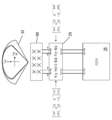
종래의 MIMO(Multiple-Input Multiple-Output) LTE 시스템에서, 각각의 송신 신호 스트림은 섹터 내에서 모든 빔 패턴들이 서로 중첩되는 별도의 기지국 안테나로 직접 라우팅되거나 맵핑된다. 세 가지 예들이 도 1-3에 도시되어 있다. In a conventional Multiple-Input Multiple-Output (LTE) LTE system, each transmit signal stream is routed or mapped directly to a separate base station antenna where all beam patterns overlap in the sector. Three examples are shown in Figs. 1-3.
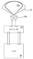
도 1은 기지국(30), 원격 무선 헤드(20, remote radio head) 및 2개의 엘리먼트(element), +/- 45° 교차-편파 안테나(10a, cross-polarized antennas)를 포함하는 종래의 2T2R MIMO LTE 기지국 시스템 기능 배치(base station system functional arrangement)를 도시한다. 이 2T2R 시스템에서, 안테나(10a)는 송신 및 수신 기능들 모두에 대해 레인지 또는 섹터(32) 내에 2 개의 고정된, 광각 중첩 빔들(33a, wide-angle overlapping beams)을 생성한다. 기지국(30)은 2 개의 송신 신호 스트림들(Tx1 및 Tx2)을 원격 헤드에 전송하고, 원격 헤드는, 일부 처리 후, 중첩하는 넓은 빔들 중 대응하는 하나를 통해 송신하기 위해 교차 편파 안테나(10a) 내의 상이한 대응하는 안테나 엘리먼트로 이들 2 개의 송신 각각을 라우팅한다. 수신기 측에서, 원격 무선 헤드(20)는 2 개의 안테나 엘리먼트들에 의해 수신된 2 개의 신호 스트림들(Rx1 및 Rx2) 각각을 수신하여 처리하고, 이들 2 개의 수신된 신호 스트림들을 기지국(30)에 제공한다. Figure 1 shows a conventional 2T2R MIMO system including a
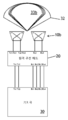
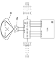
도 2는 기지국(30), 원격 무선 헤드(20), 및 2 개의 +/- 45° 교차 편파 안테나들을 포함하는 안테나 시스템(10b)을 포함하는 종래의 2T4R MIMO LTE 기지국 시스템 기능 배치를 도시한다. 이 2T4R 시스템에서, 안테나 시스템(10b)은 송신 기능에 대해 2 개의 고정된, 광각 중첩 빔들 및 수신 기능에 대해 4 개의 광각 중첩 빔들을 생성한다. 기지국(30)은 2 개의 송신 신호 스트림들(Tx1 및 Tx2)을 원격 헤드(20)에 전송하고, 원격 헤드는 각각의 송신 신호 스트림들을 교차 편파 안테나들(10b)의 하나에서 2 개의 안테나 엘리먼트들 중 대응하는 상이한 안테나 엘리먼트로 전달한다. 수신기 측에서, 원격 무선 헤드(20)는 2 개의 교차 편파 안테나 엘리먼트들에 의해 수신된 4 개의 신호 스트림(Rx1, Rx2, Rx3 및 Rx4) 각각을 수신하여 처리하고, 이들 수신된 신호들을 기지국(30)으로 송신한다. 2 illustrates a conventional 2T4R MIMO LTE base station system functional arrangement including a
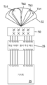
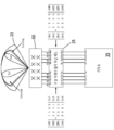
도 3은 기지국(30), 원격 무선 헤드(20) 및 2 개의 +/- 45° 교차 편파 안테나를 포함하는 안테나 시스템(10b)을 포함하는 종래의 4T4R MIMO LTE 기지국 시스템 기능 배치를 도시한다. 이 4T4R 시스템에서, 안테나 시스템(10b)은 송신 기능 및 수신 기능 모두에 대해 4 개의 고정된, 광각 중첩 빔들을 생성한다. 기지국(30)은 4 개의 송신 신호 스트림들(Tx1, Tx2, Tx3 및 Tx4)을 원격 헤드(20)에 전송하고, 원격 헤드는 각각의 송신 신호를 4 개의 안테나 엘리먼트들 중 대응하는 상이한 안테나 엘리먼트들로 전송한다. 수신기 측에서, 원격 무선 헤드(20)는 4 개의 안테나 엘리먼트들(10b)에 의해 수신된 4 개의 신호 스트림들(Rx1, Rx2, Rx3 및 Rx4) 각각을 수신하여 처리하고, 이들 4 개의 신호들을 기지국(30)에 송신한다.3 shows a conventional 4T4R MIMO LTE base station system functional arrangement including a
일반적으로 하나의 양상에서, 본 발명은 복수의 개별 송신 신호 스트림들을 포함하는 소스 신호 스트림에 의해 운반되는 정보를 무선으로 송신하기 위한 안테나 어레이를 포함하는 방법을 특징으로 한다. 상기 방법은: 상기 복수의 송신 신호 스트림들을 복수의 개별 빔 신호 스트림들에 맵핑하는 단계 - 상기 복수의 빔 신호 스트림들 중 적어도 하나의 빔 신호 스트림들은 상기 복수의 송신 신호 스트림들의 다중 송신 신호 스트림들의 조합임 - ; 복수의 송신 빔들을 생성하기 위해 상기 안테나 어레이를 사용하는 단계; 및 상기 복수의 송신 빔들 중 상이한 송신 빔을 통해 상기 복수의 빔 신호 스트림들의 각각의 빔 신호 스트림을 송신하는 단계를 포함한다.In general, in one aspect, the invention features a method comprising an antenna array for wirelessly transmitting information carried by a source signal stream comprising a plurality of discrete transmit signal streams. The method comprising the steps of: mapping the plurality of transmit signal streams to a plurality of separate beam signal streams, wherein at least one of the plurality of beam signal streams comprises a plurality of transmit signal streams of the plurality of transmit signal streams Combination; Using the antenna array to generate a plurality of transmit beams; And transmitting each beam signal stream of the plurality of beam signal streams over a different one of the plurality of transmission beams.
다른 실시 예들은 다음 특징들 중 적어도 하나를 포함한다. 상기 방법은 또한 상기 복수의 송신 신호 스트림들을 상기 복수의 개별 빔 신호 스트림들로 맵핑하기 전에, 상기 소스 신호 스트림으로부터 상기 복수의 송신 신호 스트림들을 추출하는 단계를 포함한다. 상기 복수의 송신 빔들은 독립적으로 조종 가능한 송신 빔들이다. 상기 조합은 선형 조합이다. 상기 복수의 빔 신호 스트림들의 각 빔 신호 스트림은 상기 복수의 송신 신호 스트림들의 다중 송신 신호 스트림들의 대응하는 선형 조합이다. 상기 방법은 또한 상기 복수의 송신 빔들을 통해 상기 복수의 빔 신호 스트림들을 송신하기 전에 상기 복수의 빔 신호 스트림들을 IF로 변환하는 단계를 포함한다. 상기 소스 신호 스트림은 디지털 형태이고, 상기 방법은 또한 상기 소스 신호 스트림을 디멀티플렉싱(de-multiplexing)하여 상기 복수의 송신 신호 스트림들을 생성하는 단계를 포함한다. 상기 맵핑은 디지털 도메인(digital domain)에서 수행된다. 상기 맵핑하는 단계는 상기 복수의 빔 신호 스트림들을 생성하기 위해 상기 복수의 송신 신호 스트림들에 행렬 곱셈 연산을 수행하는 단계를 포함한다. 대안적으로, 상기 소스 신호 스트림은 RF 신호이고 상기 방법은 또한 상기 복수의 송신 신호 스트림들을 상기 복수의 빔 신호 스트림들로 맵핑하기 전에 상기 복수의 송신 신호 스트림들을 IF로 하향 변환하는 단계를 포함한다. 이 경우에, 상기 복수의 개별 빔 신호 스트림들에 상기 복수의 송신 신호 스트림들을 맵핑하는 단계는 아날로그 도메인(analog domain)에서 수행된다. Other embodiments include at least one of the following features. The method also includes extracting the plurality of transmit signal streams from the source signal stream prior to mapping the plurality of transmit signal streams to the plurality of separate beam signal streams. The plurality of transmit beams are independently steerable transmit beams. The combination is a linear combination. Wherein each beam signal stream of the plurality of beam signal streams is a corresponding linear combination of multiple transmit signal streams of the plurality of transmit signal streams. The method also includes converting the plurality of beam signal streams to an IF before transmitting the plurality of beam signal streams through the plurality of transmission beams. The source signal stream is in digital form and the method also includes de-multiplexing the source signal stream to generate the plurality of transmit signal streams. The mapping is performed in a digital domain. The mapping step comprises performing a matrix multiplication operation on the plurality of transmit signal streams to generate the plurality of beam signal streams. Alternatively, the source signal stream is an RF signal and the method also includes downconverting the plurality of transmit signal streams to an IF before mapping the plurality of transmit signal streams to the plurality of beam signal streams . In this case, mapping the plurality of transmit signal streams to the plurality of individual beam signal streams is performed in an analog domain.
일반적으로, 다른 양상에서, 본 발명은 복수의 개별 송신 신호 스트림들로 구성된 소스 신호 스트림에 의해 운반되는 정보를 무선으로 송신하기 위한 안테나 시스템을 특징으로 한다. 상기 시스템은 다중 안테나 엘리먼트들 및 복수의 입력들을 갖는 안테나 어레이 시스템; 안테나 어레이 시스템을 제어하고 안테나 어레이 시스템으로 하여금 복수의 송신 빔들을 생성하도록 구성되는 제어기 - 상기 복수의 송신 빔들의 각각은 송신 빔은 상기 안테나 어레이 시스템의 복수의 입력들의 상이한 입력에 대응함 - ; 및 각각의 출력이 안테나 어레이 시스템의 대응하는 상이한 입력에 전기적으로 결합되는 복수의 출력을 갖는 신호 맵핑 모듈 - 상기 신호 맵핑 모듈은 상기 복수의 송신 신호 스트림들을 복수의 개별 빔 신호 스트림들에 맵핑하도록 구성되고, 복수의 개별 빔 신호 스트림들의 각각이 상기 신호 맵핑 모듈의 복수의 출력들의 대응하는 상이한 출력 상에 제공되고, 상기 복수의 빔 신호 스트림들 중 적어도 하나의 빔 신호 스트림들은 상기 복수의 송신 신호 스트림들의 다중 송신 신호 스트림들의 조합임 - 를 포함한다.In general, in another aspect, the invention features an antenna system for wirelessly transmitting information carried by a source signal stream comprised of a plurality of discrete transmit signal streams. The system comprising: an antenna array system having multiple antenna elements and a plurality of inputs; A controller configured to control an antenna array system and to cause an antenna array system to generate a plurality of transmit beams, each transmit beam corresponding to a different input of a plurality of inputs of the antenna array system; And a plurality of outputs, each output electrically coupled to a corresponding different input of the antenna array system, wherein the signal mapping module is configured to map the plurality of transmit signal streams to a plurality of separate beam signal streams, Wherein each of the plurality of individual beam signal streams is provided on a corresponding different output of the plurality of outputs of the signal mapping module and wherein at least one of the plurality of beam signal streams comprises a plurality of transmit signal streams A combination of multiple transmit signal streams of the same.
다른 실시 예는 다음 특징들 중 하나 이상을 포함한다. 상기 안테나 시스템은 또한 상기 소스 신호 스트림으로부터 상기 복수의 송신 신호 스트림들을 추출하고 상기 신호 맵핑 모듈에 상기 복수의 송신 신호들을 제공하기 위해, 상기 신호 맵핑 모듈과 전기적으로 결합되는 디멀티플렉서 모듈(de-multiplexer module)을 포함한다. 상기 복수의 송신 빔들은 독립적으로 조종가능한 송신 빔들이다. 상기 소스 신호 스트림은 디지털 형태이고, 상기 시스템은 또한 상기 소스 신호 스트림을 디멀티플렉싱(de-multiplexing)하여 복수의 디지털 송신 신호 스트림들을 생성하는 디멀티플렉서(de-multiplexer)를 포함한다. 이 경우에, 상기 신호 맵핑 모듈은 디지털 도메인(digital domain)에서 상기 맵핑을 수행한다. 상기 안테나 어레이는 또한 상기 복수의 송신 빔들을 통해 상기 복수의 빔 신호 스트림들을 송신하기 전에 상기 복수의 빔 신호 스트림들을 IF로 변환하기 위한 디지털-IF 변환기(digital-to-IF converter)를 포함한다. 상기 소스 신호 스트림은 RF 신호이다. 상기 안테나 시스템은 또한 상기 신호 맵핑 모듈이 상기 복수의 개별 빔 신호 스트림들에 상기 복수의 송신 신호 스트림들을 맵핑하기 전에 상기 복수의 송신 신호 스트림들을 IF로 하향 변환하는 하향 변환기를 포함한다. 상기 신호 맵핑 모듈은 아날로그 도메인(analog domain)에서 맵핑을 수행한다. 상기 조합은 선형 조합이다. 복수의 빔 신호 스트림들의 각각의 빔 신호 스트림은 복수의 송신 신호 스트림들의 다중 송신 신호 스트림들의 대응하는 선형 조합이다. 신호 맵핑 모듈은 복수의 빔 신호 스트림들을 생성하기 위해 복수의 송신 신호 스트림들에 행렬 곱셈 연산을 수행하도록 구성된다.Other embodiments include one or more of the following features. The antenna system may further include a de-multiplexer module, electrically coupled to the signal mapping module, for extracting the plurality of transmit signal streams from the source signal stream and for providing the plurality of transmit signals to the signal mapping module. ). The plurality of transmit beams are independently steerable transmit beams. The source signal stream is in digital form and the system also includes a de-multiplexer that de-multiplexes the source signal stream to produce a plurality of digital transmit signal streams. In this case, the signal mapping module performs the mapping in a digital domain. The antenna array also includes a digital-to-IF converter for converting the plurality of beam signal streams to an IF before transmitting the plurality of beam signal streams through the plurality of transmission beams. The source signal stream is an RF signal. The antenna system also includes a downconverter that downconverts the plurality of transmit signal streams to an IF before the signal mapping module maps the plurality of transmit signal streams to the plurality of separate beam signal streams. The signal mapping module performs mapping in an analog domain. The combination is a linear combination. Each beam signal stream of the plurality of beam signal streams is a corresponding linear combination of the plurality of transmitted signal streams of the plurality of transmitted signal streams. The signal mapping module is configured to perform a matrix multiplication operation on the plurality of transmit signal streams to generate a plurality of beam signal streams.
일반적으로, 또 다른 양상에서, 본 발명은 안테나 어레이를 포함하는 방법을 특징으로 한다. 이 방법은, 복수의 수신 빔들을 생성하기 위해 상기 안테나 어레이를 사용하는 단계; 상기 복수의 수신 빔들을 통해 상기 복수의 빔 신호 스트림들을 수신하는 단계 - 상기 복수의 빔 신호 스트림들의 각각의 빔 신호 스트림은 상기 복수의 수신 빔들의 상이한 대응하는 수신 빔을 통해 수신됨 - ; 및 상기 복수의 빔 신호 스트림들을 복수의 개별 수신된 신호 스트림들에 맵핑하는 단계 - 상기 복수의 수신된 신호 스트림들 중 적어도 하나의 수신된 신호 스트림들은 상기 복수의 빔 신호 스트림들의 다중 빔 신호 스트림들의 조합임 - 를 포함한다.In general, in another aspect, the invention features a method comprising an antenna array. The method includes using the antenna array to generate a plurality of receive beams; Receiving the plurality of beam signal streams through the plurality of receive beams, wherein each beam signal stream of the plurality of beam signal streams is received via a different corresponding receive beam of the plurality of receive beams; And mapping the plurality of beam signal streams to a plurality of individually received signal streams, wherein at least one received signal streams of the plurality of received signal streams are multiplexed with a plurality of beam signal streams of the plurality of beam signal streams Combination.
다른 실시 예들은 다음 특징들 중 하나 이상을 포함한다. 조합은 선형 조합이다. 상기 복수의 수신된 신호 스트림들의 각 수신된 신호 스트림은 상기 복수의 빔 신호 스트림들의 다중 빔 신호 스트림들의 대응하는 선형 조합이다. 상기 맵핑하는 단계는 복수의 수신된 신호 스트림을 생성하기 위해 복수의 빔 신호 스트림들에 행렬 곱셈 연산을 수행하는 단계를 포함한다. 상기 방법은 복수의 수신된 신호 스트림들을 합성 신호 스트림으로 멀티플렉싱하는 단계를 더 포함한다. 복수의 수신 빔들은 독립적으로 조종 가능한 수신 빔들이다. 상기 빔 신호 스트림은 IF 신호들이고, 상기 방법은 또한 상기 복수의 빔 신호 스트림들을 상기 복수의 개별 수신된 신호 스트림들로 맵핑하기 전에 IF로부터 디지털로 상기 복수의 빔 신호 스트림들을 변환하는 단계를 포함한다. 상기 맵핑은 디지털 도메인(digital domain)에서 수행된다. Other embodiments include one or more of the following features. The combination is a linear combination. Each received signal stream of the plurality of received signal streams is a corresponding linear combination of the multiple beam signal streams of the plurality of beam signal streams. The mapping step includes performing a matrix multiplication operation on the plurality of beam signal streams to generate a plurality of received signal streams. The method further comprises multiplexing the plurality of received signal streams into a composite signal stream. The plurality of receive beams are independently controllable receive beams. The beam signal stream is IF signals and the method also includes converting the plurality of beam signal streams to digital from the IF before mapping the plurality of beam signal streams to the plurality of individually received signal streams . The mapping is performed in a digital domain.
일반적으로, 또 다른 양상에서, 본 발명은 안테나 시스템이: 다중 안테나 엘리먼트들을 갖는 안테나 어레이 시스템; 안테나 어레이 시스템을 제어하고 안테나 어레이 시스템으로 하여금 복수의 빔 신호 스트림들을 수신하기 위한 복수의 수신 빔들을 생성하도록 구성되는 제어기 - 상기 복수의 수신 빔들의 각각은 상기 복수의 빔 신호 스트림들의 대응하는 빔 신호 스트림을 생성하기 위한 것임 - ; 및 안테나 어레이 시스템에 전기적으로 결합되고 복수의 출력들을 갖는 신호 맵핑 모듈 - 상기 신호 맵핑 모듈은 상기 복수의 수신 신호 스트림들을 복수의 개별 수신된 신호 스트림들에 맵핑하도록 구성되고, 복수의 개별 수신된 신호 스트림들의 각각이 상기 신호 맵핑 모듈의 복수의 출력들의 대응하는 상이한 출력 상에 제공되고, 상기 복수의 수신된 신호 스트림들 중 적어도 하나의 수신된 신호 스트림들은 상기 복수의 빔 신호 스트림들의 다중 빔 신호 스트림들의 조합임 - 를 포함하는 것을 특징으로 한다.In general, in another aspect, the invention provides an antenna system comprising: an antenna array system having multiple antenna elements; A controller configured to control an antenna array system and to cause an antenna array system to generate a plurality of receive beams for receiving a plurality of beam signal streams, each of the plurality of receive beams including a corresponding beam signal of the plurality of beam signal streams To generate a stream; And a signal mapping module electrically coupled to the antenna array system and having a plurality of outputs, the signal mapping module being configured to map the plurality of received signal streams to a plurality of respective received signal streams, Each of the streams being provided on a corresponding different output of the plurality of outputs of the signal mapping module and wherein at least one of the plurality of received signal streams comprises a plurality of beam signal streams of the plurality of beam signal streams, And a combination of the two.
다른 실시 예들은 다음 특징들 중 하나 이상을 포함한다. 상기 조합은 선형 조합이다. 상기 복수의 수신된 신호 스트림들의 각 수신된 신호 스트림은 상기 복수의 빔 신호 스트림들의 다중 빔 신호 스트림들의 대응하는 선형 조합이다. 상기 맵핑은 상기 복수의 수신된 신호 스트림들을 생성하기 위해 상기 복수의 빔 신호 스트림들에 행렬 곱셈 연산을 수행하는 것을 포함한다. 상기 안테나 시스템은 또한 복수의 수신된 신호 스트림들을 합성 신호 스트림으로 멀티플렉싱하기 위해 상기 신호 맵핑 모듈에 전기적으로 결합된 멀티플렉서 모듈을 포함한다.Other embodiments include one or more of the following features. The combination is a linear combination. Each received signal stream of the plurality of received signal streams is a corresponding linear combination of the multiple beam signal streams of the plurality of beam signal streams. The mapping includes performing a matrix multiplication operation on the plurality of beam signal streams to generate the plurality of received signal streams. The antenna system also includes a multiplexer module electrically coupled to the signal mapping module for multiplexing the plurality of received signal streams into a composite signal stream.
본 발명의 하나 이상의 실시 예들의 세부 사항들은 첨부된 도면들 및 이하의 설명에서 설명된다. 본 발명의 다른 특징들, 목적들 및 이점들은 상세한 설명 및 도면들 및 청구 범위들로부터 명백해질 것이다.The details of one or more embodiments of the invention are set forth in the accompanying drawings and the description below. Other features, objects, and advantages of the invention will be apparent from the description and drawings, and from the claims.
도 1은 종래의 2T2R MIMO LTE 기지국 시스템 기능 배치를 나타낸다.
도 2는 종래의 2T4R MIMO LTE 기지국 시스템 기능 배치를 나타낸다.
도 3은 종래의 4T4R MIMO LTE 기지국 시스템 기능 배치를 나타낸다.
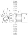
도 4는 4 개의 빔들을 갖는 위상 어레이 4T4R MIMO LTE 기지국 시스템 기능 배치를 도시한다.
도 5는 4 개의 빔들을 갖는 다른 위상 어레이 4T4R MIMO LTE 기지국 시스템 기능 배치를 도시한다.
도 6은 +45°/-45° 교차 편파 안테나 어레이를 사용하여 0°/90° 편광 빔들을 생성하는 것을 도시한다.
도 7은 +45°/-45° 교차 편파 안테나 어레이를 사용하여 RHCP 및 LHCP 빔들을 생성하는 것을 도시한다.
도 8은 단일 종래의 교차 편파 안테나에 4T4R을 맵핑하는 것을 도시한다.
도 9는 추가적인 다이버시티를 갖는 단일 종래 교차 편파 안테나에 4T4R를 맵핑하는 것을 도시한다.
도 10은 완전한 오버헤드 커버리지 및 추가적인 핫스팟 커버리지를 갖는 위상 어레이 4T4R을 도시한다.
도 11은 Tx 및 Rx 행렬 곱셈을 구현하는 디지털 실시 예의 기능 블록도를 도시한다.
도 12는 Tx 및 Rx 행렬 곱셈을 구현하는 RF 실시 예의 기능 블록도를 도시한다.
도 13은 안테나 어레이의 하나의 안테나 엘리먼트에 연결된 프론트 엔드 모듈의 블록도이다.
도 14는 다중 안테나 엘리먼트들을 갖는 능동 안테나 어레이 시스템의 송신기 측의 블록도이다.
도 15는 다중 안테나 엘리먼트들을 갖는 능동 안테나 어레이 시스템의 수신기 측의 블록도이다.
이전의 도면들에서, 유사한 엘리먼트들은 동일한 참조 번호들로 식별될 수 있다.Figure 1 shows a conventional 2T2R MIMO LTE base station system functional arrangement.
Figure 2 shows a conventional 2T4R MIMO LTE base station system functional arrangement.
3 illustrates a conventional 4T4R MIMO LTE base station system function arrangement.
Figure 4 shows a phased array 4T4R MIMO LTE base station system functional arrangement with four beams.
5 shows another phase array 4T4R MIMO LTE base station system functional arrangement with four beams.
Figure 6 shows the generation of 0 ° / 90 ° polarized beams using a + 45 ° / -45 ° cross polarization antenna array.
Figure 7 shows the generation of RHCP and LHCP beams using a + 45 ° / -45 ° cross polarization antenna array.
Figure 8 shows mapping 4T4R to a single conventional cross-polarized antenna.
Figure 9 shows mapping of 4T4R to a single conventional cross-polarized antenna with additional diversity.
Figure 10 shows a phased array 4T4R with full overhead coverage and additional hotspot coverage.
Figure 11 shows a functional block diagram of a digital embodiment for implementing Tx and Rx matrix multiplication.
Figure 12 shows a functional block diagram of an RF embodiment that implements Tx and Rx matrix multiplication.
Figure 13 is a block diagram of a front end module coupled to one antenna element of the antenna array.
14 is a block diagram of a transmitter side of an active antenna array system with multiple antenna elements.
15 is a block diagram of a receiver side of an active antenna array system with multiple antenna elements.
In the preceding figures, like elements may be identified with the same reference numerals.
여기에 설명된 접근법은 무선 통신 시스템 내에서 사용되고 기지국 또는 모바일 중 어느 하나에 적용될 수 있지만, 기지국에서 보다 많이 사용된다. 위상 배열 안테나 시스템 내에서 사용되지만, 종래의 안테나 시스템에도 사용될 수 있다. The approach described herein is used in a wireless communication system and can be applied to either a base station or a mobile, but is more commonly used in a base station. Although used in a phased array antenna system, it can also be used in conventional antenna systems.
이하의 실시 예들은 기지국 송신기로 설명되지만, 이 원리들은 후술하는 바와 같이 수신기에도 적용된다. 설명된 실시 예는 3GPP LTE(3rd Generation Partnership Project Long-Term Evolution) 표준을 따르지만, 이 원리들은 임의의 일반적인 다중 스트림 통신 시스템에 적용된다. The following embodiments are described as a base station transmitter, but these principles also apply to the receiver as described below. The described embodiments conform to the 3GPP LTE (3 rd Generation Partnership Project Long-Term Evolution) standard, but these principles apply to any common multi-stream communication system.
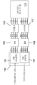
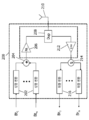
도 4에 도시된 것과 같은, 위상 어레이 안테나 시스템은 본 명세서에서 개발된 아이디어들을 예시하기 위해 사용될 것이다. 그것은 위상 어레이 안테나(50)를 동작시키는 원격 위상 어레이 무선 헤드(25)와 통신하는 기지국(35)을 포함한다. 이 시스템에서, 다중 빔들이 섹터 내에서 형성될 수 있으며, 일부는 아마도 중첩되고 일부는 중첩되지 않을 수 있다. 이 특정 실시 예에서, 기지국(35)은 4 개의 송신 신호 스트림들(Tx1, Tx2, Tx3 및 Tx4)을 원격 무선 헤드(25)에 전송하고, 원격 무선 헤드(25)로부터 4 개의 수신된 신호 스트림들(Rx1, Rx2, Rx3 및 Rx4)을 수신한다. 원격 무선 헤드(25)는, 차례로, 4 개의 빔, 즉 각각의 송신 빔 신호 스트림에 대해 하나의 빔을 생성하기 위해, 안테나 어레이(50)에 4 개의 송신 빔 신호 스트림(Tb1, Tb2, Tb3 및 Tb4)을 송신하고, 4개의 신호 스트림들(Rb1, Rb2, Rb3 및 Rb4)을 안테나 어레이(50)로부터 수신한다. 일반적으로, 각각의 송신 신호 스트림(Tx1, Tx2, Tx3 및 Tx4)은 대응하는 상이한 빔에 맵핑된다. 그러나, 이러한 시스템에서, 2 개 이상의 송신 신호 스트림들의 선형 조합을 단일 안테나 빔에 송신하는 것이 매우 유리할 수 있다. 그렇게 하기 위해, 시스템(예를 들어, 무선 헤드)은 다중 송신 신호 스트림들을 선형적으로 결합하여 송신 빔 신호 스트림들 중 하나를 생성하도록 수정된다. A phased array antenna system, such as that shown in Figure 4, will be used to illustrate the ideas developed herein. It includes a base station (35) in communication with a remote phased array radio head (25) which operates a phased array antenna (50). In this system, multiple beams can be formed in a sector, some possibly overlapping and some not overlapping. In this particular embodiment, the
이러한 개념의 일반적인 구현이 이제 특정 예들에 의해 기술되고 예시될 것이다. The general implementation of this concept will now be described and illustrated by specific examples.
안테나 어레이에 의해 형성된 n 개의 입력 송신 신호 스트림들 및 m 개의 출력 송신 빔들을 갖는 다중 스트림 통신 시스템을 고려한다. 입력 송신 신호 스트림들(Tx1 내지 Txn)을 각각의 송신 빔(TB1 내지 TBm)에 맵핑하는 것은 선형 조합 행렬(M)을 통해 달성된다:Consider a multi-stream communication system having n input transmit signal streams and m output transmit beams formed by an antenna array. Mapping the input transmission signal streams Tx 1 to Tx n to the respective transmission beams TB 1 to TB m is achieved through a linear combination matrix M:
[TB] = [M] [Tx][TB] = [M] [Tx]
행렬들을 확장함:Expand matrices:

명백한 바와 같이, 임의의 수의 입력 스트림들이 임의의 수의 위상 어레이 안테나 빔들에 임의의 선형 조합으로 맵핑될 수 있다. 다르게 말하면, 가장 일반적인 의미에서, 각각의 안테나 빔에 대한 맵핑은 그 빔에 대한 입력 스트림들의 가중된 합계이다. 이는 4 개의 송신 신호 스트림들이 4 개의 빔들(즉, m = 4 및 n = 4)으로 맵핑되는 경우에 대해 도 5에 도시된다. As is evident, any number of input streams may be mapped to any number of phased array antenna beams in any linear combination. In other words, in its most general sense, the mapping for each antenna beam is the weighted sum of the input streams for that beam. This is illustrated in FIG. 5 for the case where four transmit signal streams are mapped to four beams (i.e., m = 4 and n = 4).
어떤 경우들에서는, 입력들의 일부의 위상뿐만 아니라 크기를 변경하는 것이 유리하다. 이것은 선형 조합 행렬에 위상 컴포넌트를 부가함으로써 쉽게 수행될 수 있다. 선형 조합 행렬(M)의 각각의 행렬 요소(Mij)는 스케일러(scaler) 및 위상 조정(phase adjustment)의 곱이 될 것이다: Mij=Aij (ejθij), 여기서, Aij는 크기 승수(multiplier)이고, θij는 위상 시프트이다. In some cases, it is advantageous to change the size as well as the phase of some of the inputs. This can be easily accomplished by adding a phase component to the linear combination matrix. Each matrix element M ij of the linear combination matrix M will be the product of a scaler and a phase adjustment: M ij = A ij (e j ? Ij ), where A ij is the magnitude multiplier multiplier, and [theta] ij is the phase shift.
다음은 이것이 실용적인 시스템에서 어떻게 사용될 것인지의 예이다. 4 개의 독립적인 데이터 스트림들을 송신하고 교차 폴 안테나 엘리먼트 어레이 행렬(cross-pol antenna element array matrix)로 형성된 4 개의 빔들에 맵핑되는 4T4R MIMO 기지국을 고려한다. 3GPP LTE에서, 오버헤드 심볼들은 4 개의 송신 신호 스트림들(Tx1 및 Tx2) 중 2 개에 걸쳐 확산되고 그 다음 나머지 두 개의 송신 신호 스트림들(Tx3 및 Tx4)에 대한 알라무티(Alamouti) 코딩을 사용하여 반복된다. 위상 어레이 시스템이 4 개의 빔들로, +45° 편파를 갖는 2 개의 빔들 및 -45° 편파를 갖는 다른 2 개의 빔들로, 제한되는 경우, 신호들(Tx1 및 Tx2)의 동일하게 가중된 선형 조합을 단일 빔이 섹터를 통해 넓게 퍼져서 오버헤드 채널들 모두가 모바일들이 셀에 래치할 수 있도록 한다. 이것은 섹터 내의 핫스팟 영역들에 대해 아마도 더욱 좁게 포커싱된 빔들 상의 입력 스트림들의 개별 입력 스트림 송신 또는 상이한 선형 조합들을 위해 다른 3 개의 빔들을 자유롭게 해준다. The following is an example of how this would be used in a practical system. Consider a 4T4R MIMO base station that transmits four independent data streams and maps to four beams formed of a cross-pol antenna element array matrix. In 3GPP LTE, the overhead symbols are spread over two of the four transmit signal streams Tx 1 and Tx 2 and then spread over two of the remaining transmit signal streams Tx 3 and Tx 4 , ) Coding. If the phased array system is limited to four beams, two beams with +45 DEG polarization and two other beams with -45 DEG polarization, the signals (Tx 1 and Tx 2 ) are equally weighted linear The combination allows a single beam to spread widely through the sector so that all of the overhead channels allow the mobiles to latch onto the cell. This frees up the other three beams for separate input streams transmission or different linear combinations of input streams on possibly more narrowly focused beams for hotspot areas within the sector.
추가적인 다이버시티는 입력 신호들의 위상을 회전시키고 이들을 서로 대향하는 안테나 엘리먼트 편파들에 적절히 공급하여, 도 6에 예시된 바와 같이, +45°/-45° 안테나 쌍으로부터 아마도 0°/90° 편광된 파형을 생성함으로써 달성될 수 있다. 대안적으로, 도 7에 예시된 바와 같이 적절하게 선택된 위상 시프트를 사용함으로써, 시스템은 RHCP(right hand circularly polarized) 또는 LHCP(left hand circularly polarized) 전파를 생성할 수 있다. 이러한 몇몇 예들로부터, 이 방식으로는 가능한 많은 가능성들이 있음이 명백해야 한다. Additional diversity may be achieved by rotating the phase of the input signals and appropriately feeding them to opposing antenna element polarizations to produce a polarization of 0 ° / 90 ° polarized from a + 45 ° / -45 ° antenna pair, as illustrated in FIG. 6 Can be achieved by generating a waveform. Alternatively, by using a properly selected phase shift as illustrated in FIG. 7, the system can generate right hand circularly polarized (RHCP) or left hand circularly polarized (LHCP) radio waves. From these few examples it should be clear that there are as many possibilities in this way as possible.
수신 방향을 고려하라. 4T4R MIMO LTE 시스템에서, 최소 평균 제곱 에러(MMSE, minimum mean square error) 방식으로 가산되고 기지국 모뎀에서 복조되는 4 개의 대응하는 수신 스트림들이 존재할 것이다. 종래의 기지국의 경우, 각각의 수신 스트림은 각 송신 스트림에 대응하므로, 각 안테나와 각 수신 스트림 사이에 일대일 대응이 존재할 것이다. 안테나 어레이의 경우에서, 빔들의 수와 수신 스트림들의 수 사이에 일대일 대응이 존재하지 않을 수 있으므로, 각 빔으로부터의 수신 정보는 네 개의 모든 수신 경로들이 활용되고 있는 것이 확인되도록 각 수신 스트림에 전송(맵핑)되어야 한다. Consider the receiving direction. In a 4T4R MIMO LTE system, there will be four corresponding receive streams that are added in the minimum mean square error (MMSE) manner and demodulated in the base station modem. In the case of a conventional base station, each receive stream corresponds to each transmit stream, so there will be a one-to-one correspondence between each antenna and each receive stream. In the case of an antenna array, there may not be a one-to-one correspondence between the number of beams and the number of received streams, so that the received information from each beam is transmitted to each received stream so that all four receive paths are utilized Mapping).
수신 측은 역방향으로, 즉, 수신 빔으로부터 수신 스트림으로, 맵핑된다. 수신 빔들(RB1 내지 RBm)을 각각의 출력 수신 스트림(Rx1 내지 Rxn)으로 맵핑하는 것은 선형 조합 행렬 L을 통해 이루어진다:The receiving side is mapped in the reverse direction, i.e., from the receiving beam to the receiving stream. The map the receive beams (RB 1 to RB m) to each of the received output stream (Rx 1 through Rx n) takes place through a linear combination matrix L:
[Rx] = [L] [RB][Rx] = [L] [RB]
행렬을 확장함:Expands the matrix:

일부 경우에서는, 입력들의 일부의 위상뿐만 아니라 크기를 변경하는 것이 유리하다. 송신 경우에서와 같이, 이는 선형 조합 행렬에 위상 컴포넌트를 추가함으로써 쉽게 수행될 수 있다. 선형 조합 행렬(L)의 각각의 행렬 엘리먼트(Lij)는 스케일러 및 위상 조정의 곱셈이 될 것이다: Lij=Aij (ejθij), 여기서, Aij는 크기 승수이고, θij는 위상 시프트이다. 또한, 송신 행렬(M) 내의 엘리먼트들은 수신 행렬(L) 내의 엘리먼트들과는 완전히 다를 수 있다. In some cases, it is advantageous to change the phase as well as the magnitude of a portion of the inputs. As in the case of transmission, this can be easily done by adding a phase component to the linear combination matrix. Each of the matrix elements of the linear combination matrix (L) (L ij) will be the multiplication of a scalar and phase adjustment: L ij = A ij (e jθij), wherein, A ij is the size of the multiplier, θ ij is a phase shift to be. In addition, the elements in the transmission matrix M may be completely different from the elements in the reception matrix L. [
4 개의 빔들을 형성하는 4T4R 위상 어레이 시스템은 송신 및 수신 모두에 대해 4x4 맵핑 행렬을 요구할 것이다:A 4T4R phased array system that forms four beams will require a 4x4 mapping matrix for both transmit and receive:


여기에서 핵심 개념은 제한된 수의 종래의 안테나들 또는 안테나 어레이에서 생성될 수 있는 제한된 수의 빔들의 사용을 최적화하기 위해, 다중 스트림 통신 시스템의 입력들의 선형 조합들을 생성하는 아이디어이다. 추가적인 종래의 안테나를 추가하는 것은 타워 구역 제한들(tower zoning restriction) 및 임대 비용(rental fees)으로 인하여 종종 실용적이지 않으며, 안테나 어레이에서 추가적인 빔들을 생성하는 능력은 이용 가능한 시스템 하드웨어 또는 소프트웨어에 의해 제한될 수 있다. The key concept here is the idea of creating linear combinations of inputs of a multi-stream communication system to optimize the use of a limited number of conventional antennas or a limited number of beams that can be generated in an antenna array. Adding additional conventional antennas is often impractical due to tower zoning restrictions and rental fees and the ability to generate additional beams in the antenna array is limited by available system hardware or software .
종래의 안테나의 예. 어떤 유형의 타워 제한(예를 들어, 공간, 구역화, 비용)으로 인해 서비스 제공자가 단일 교차 편파 종래의 안테나(10a)로 제한되는 4T4R 무선 통신 시스템을 고려한다. 무선 헤드(28)(도 8 참조)에서 구현될 수 있는 하나의 솔루션은 4 개의 송신 스트림들 중 2 개(예를 들어, Tx1 및 Tx2)를 선형적으로 결합하여 이들을 +45° 안테나 편파로 공급하는 것이고, 도 8에 도시된 바와 같이, 나머지 두 개의 송신 스트림들(예를 들어, Tx3 및 Tx4)을 선형적으로 결합하여 -45° 안테나 편파로 공급한다. An example of a conventional antenna . Consider a 4T4R wireless communication system in which a service provider is limited to a single cross polarization
추가적인 다이버시티 이득을 허용할 수 있는 제 2 솔루션은, +45°에서의 Tx1(경사 편광, slant polarization), -45°에서의 Tx2(경사 편광), 0°에서의 Tx3(수직 편광, vertical polarization) 및 +90°에서의 Tx4와 같이, 4 개의 스트림 모두를 상이한 편광들로 방사하는 방식으로, 교차 편파 안테나의 2 개의 입력에 4 개의 송신 스트림 모두의 선형 조합을 공급하는 것이다. 이것은 도 9에 예시된다. A second solution that may allow for additional diversity gain is Tx1 (slant polarization) at + 45 degrees, Tx2 (oblique polarization) at -45 degrees, Tx3 (vertical polarization ) And Tx4 at + 90 [deg.], In such a way as to radiate all four streams to different polarizations, to the two inputs of the cross-polarized antenna. This is illustrated in FIG.
어느 경우에나, 수신기 측에서, 수신된 신호들은 전형적으로 송신기 측의 선형 조합 및/또는 편광과 정합하는 방식으로 결합될 수 있다. In either case, at the receiver side, the received signals may be combined in a manner that typically matches the linear combination and / or polarization of the transmitter side.
위상 배열 안테나의 예. 어떤 유형의 장비 제한(예를 들어, 하드웨어/소프트웨어)으로 인해 안테나 어레이(50)로 형성될 수 있는 빔들의 수가 4로 제한되는 4T4R 무선 통신 시스템을 고려한다. 간단한 솔루션은 송신 스트림들 각각을 고유한 송신 빔에 개별적으로 할당하는 것이다. 그러나, 이러한 기본 배치는 섹터(32) 내의 빔들의 최적의 배치(optimal placement)를 제한하는데, 그 이유는 3GPP LTE 시스템에서 모바일들이 셀들에 고정되기 위해서 4 개의 빔들 중 2 개가 중첩 빔들로 전체 섹터를 커버할 필요가 있기 때문이다. An example of a phased array antenna . Consider a 4T4R wireless communication system in which the number of beams that can be formed into the
하나의 솔루션은 4 개의 송신 스트림들 중 2 개(예를 들어, Tx1 및 Tx2)를 선형적으로 결합하고 그들을 +45° 안테나 편파에서 빔 1로 공급하고, 나머지 두 개의 송신 스트림들(예를 들어, Tx3 및 Tx4)을 선형적으로 결합하고 -45° 안테나 편파에서 빔 2로 공급하는 것이다. 이는 개별 또는 선형으로 조합된 송신 스트림들의 핫스팟 커버리지에 대해 빔 3 및 빔 4를 자유롭게 한다. 이것은 도 10에 예시된다. One solution linearly combines two of the four transmit streams (e.g., Tx1 and Tx2) and feeds them to
최적의 섹터 커버리지를 위해 3 개의 빔을 자유롭게 하지만, 다이버시티 트레이드 오프를 갖는, 4 개의 송신 스트림들 모두의 조합을 포함하는 단일 빔을 생성하는 것과 같은 추가적인 해결책이 가능하다. 마지막으로, 각 빔의 편광, 또는 중첩하는 빔들 상의 특정 개별적인 또는 선형적으로 결합된 송신 스트림 조합들의 편광은 다이버시티 향상을 위해 앞서 논의된 바와 같이 변경될 수 있다. Additional solutions are possible, such as generating a single beam that frees three beams for optimal sector coverage, but with a combination of all four transmit streams, with diversity trade-offs. Finally, the polarization of each beam, or the polarization of certain individual or linearly combined transmission stream combinations on overlapping beams, may be changed as discussed above for diversity enhancement.
위상 어레이 시스템들은 각 빔의 앙각(elevation angle)을 기울어지게 하거나(skewing) 중첩하는 빔들의 방위각(azimuth angle)을 기울어지게 하거나, 또는 이들과 상기 다이버시티 방식들의 조합과 같은, 종래의 안테나 시스템들에 비해 부가적인 다이버시티 옵션들을 위한 유연성을 제공한다. The phased array systems may either skew the elevation angle of each beam or incline the azimuth angle of the overlapping beams, or may be used in conjunction with conventional antenna systems, such as a combination of these and the diversity schemes To provide flexibility for additional diversity options.
도 11은 송신 측 및 수신 측에서 행렬 곱셈을 사용하는 예시적인 디지털 기지국 인터페이스 구현을 도시한다. CPRI(Common Public Radio Interface) 모듈(100)은 Rx 및 Tx 신호들을 무선 헤드로 및 무선 헤드로부터 전달하는 호스트 기지국(도시되지 않음)으로부터의 링크에 대한 인터페이스를 제공한다. 본 명세서 및 이하의 설명에서의 혼란을 피하기 위해, 기지국은 두 개의 인터페이스 포인트: 즉 기지국의 기저 대역 처리 유닛에 대한 디지털 CPRI 인터페이스(도 1의 경우와 같이)를 가질 수 있거나, 또는 기지국 무선기 또는 기지국 RF 헤드에 대한 직접 RF 인터페이스(이하에서 논의되는 도 12의 경우와 같이)를 포함할 수 있다. 11 illustrates an exemplary digital base station interface implementation using matrix multiplication on the transmit and receive sides. The CPRI (Common Public Radio Interface)
신호들은 CPRI 프레임들로서 기지국과 무선 헤드 사이에서 교환된다. CPRI 모듈(100) 내에는, 기지국에 의해 송신된 CPRI 프레임으로부터 다중 디지털 송신 신호들(DTx1, DTx2, DTx3, 및 DTx4)을 추출하는 디멀티플렉서 또는 CPRI 디프레임 기능(102, de-framing function)이 있다. 그 다음, 이들 신호 스트림들은 복수의 송신 빔 신호들(BTx1, BTx2, BTx3 및 BTx4)을 생성하는 프로세싱 모듈(106)에 제공되며, 각각은 프로세싱 모듈(106)에 의해 수신되는, 적어도 하나의 디지털 송신 신호 스트림들의 선형 조합이다. 프로세싱 모듈(106)은 디지털 송신 신호들로부터 선형 조합을 생성하기 위해 이전에 기술된 타입의 행렬 곱셈을 수행하기 위해 사용하는 디지털 행렬 곱셈기들(digital matrix multipliers) 및 가산기들(adders)을 포함한다. 결과적인 송신 빔 신호들은 디지털-IF 변환기(110)에 의해 IF 신호들로 변환되고, 결과적인 IF 빔 신호들(ITx1, ITx2, ITx3 및 ITx4)은 능동 안테나 어레이 시스템(114)에 제공되고 무선 전송을 위해 RF로 변환된다. 이하 더 상세히 기술되는, 능동 안테나 어레이 시스템(114)은 송신 빔 신호들이 송신되는 4 개의 빔뿐만 아니라 IF-RF 변환을 생성하는데 사용되는, 빔 형성 및 빔 맵핑 기능을 포함한다. The signals are exchanged between the base station and the wireless head as CPRI frames. Within the
수신기 측에서, 수신된 RF 빔 신호들은 능동 안테나 어레이 시스템 (114)에서 IF 신호(IRx1, IRx2, IRx3 및 IRx4)로 하향 변환되고, 이들 IF 신호들은 IF-디지털 변환기(112)에 의해 디지털 수신된 빔 신호들(BRx1, BRx2, BRx3, 및 BRx4)로 변환된다. 이들 신호들는 복수의 디지털 수신된 신호들(DRx1, DRx2, DRx3, 및 DRx4)을 생성하는 프로세싱 모듈(108)에 제공되며, 각각은 프로세싱 모듈(108)에 의해 수신된 빔 신호들 중 적어도 하나의 선형 조합이다. 프로세싱 모듈(108)은 수신된 빔 신호들의 선형 조합을 생성하기 위해 이전에 기술된 유형의 행렬 곱셈을 수행하기 위해 사용하는 디지털 행렬 곱셈기 및 가산기를 포함한다. CPRI 모듈(100) 내의 멀티플렉서 또는 CPRI 프레이밍 기능(104)은 기지국으로 다시 송신하기 위해 복수의 디지털 수신 신호를 CPRI 프레임으로 조립한다. At the receiver side, the received RF beam signals are down-converted to IF signals IRx1, IRx2, IRx3 and IRx4 in the active
설명된 실시 예에서, CPRI 모듈(100) 및 프로세싱 모듈(106 및 108)의 행렬 곱셈 연산은 필요한 기능들을 수행하도록 적절하게 프로그래밍된 FPGA(또는 다른 프로세서 엘리먼트들)를 사용하여 구현된다. 디지털-IF 변환기(110) 및 IF-디지털 변환기(112)는 디지털-아날로그 및 아날로그-디지털 회로를 사용하는 하드웨어로 구현된다. In the described embodiment, the matrix multiplication operations of
도 12는 송신 측 및 수신 측에서 행렬 곱셈을 사용하는 RF 기지국 인터페이스 구현의 예를 도시한다. 이 경우, 기지국 신호들는 RF 송신 신호들(Tx1, Tx2, Tx3 및 Tx4)로서 원격 무선 헤드에 송신되고 원격 무선 헤드로부터 수신된다. 이들 신호들은 RF-IF 변환기(126)에 의해 대응하는 IF 송신 신호들(ITx1, ITx2, ITx3 및 ITx4)로 변환된다. 이들 IF 송신 신호는 복수의 빔 송신 신호(BTx1, BTx2, BTx3 및 BTx4)를 생성하는 프로세싱 모듈(130)에 제공되고, 각각은, 프로세싱 모듈(130)에 의해 수신되는, 적어도 하나의 IF 송신 신호의 선형 조합이다. 프로세싱 모듈(130)은 IF 송신 신호들의 선형 조합을 생성하기 위해, 앞서 기술된 유형의 행렬 곱셈을 수행하기 위해 사용하는 디지털 행렬 곱셈기 및 가산기를 포함한다. 결과적인 빔 신호들을(BTx1, BTx2, BTx3, 및 BTx4)은 능동 안테나 어레이 시스템(114)에 제공되고, 무선 송신을 위해 RF로 변환된다. 전술한 바와 같이, 능동 안테나 어레이 시스템(114)은 송신 빔 신호들이 송신되는 4 개의 빔들뿐만 아니라 IF-RF 변환을 생성하는데 사용되는 빔 형성 및 빔 맵핑 기능을 포함한다. Figure 12 shows an example of an RF base station interface implementation using matrix multiplication on the transmit and receive sides. In this case, the base station signals are transmitted to and received from the remote radio head as RF transmission signals (Tx1, Tx2, Tx3 and Tx4). These signals are converted to corresponding IF transmission signals (ITx1, ITx2, ITx3 and ITx4) by the RF-to-
수신기 측에서, 능동 안테나 어레이로부터 수신된 IF 빔 신호들, BRx1, BRx2, BRx3 및 BRx4는 복수의 수신된 IF 신호들(IRx1, IRx2, IRx3, 및 IRx4)을 생성하는 프로세싱 모듈(132)에 제공되고, 각각은 프로세싱 모듈에 의해 수신되는 적어도 하나의 IF 빔 신호들의 선형 조합이다. 프로세싱 모듈은 IF 송신 신호들의 선형 조합을 생성하기 위해 이전에 기술된 유형의 행렬 곱셈을 수행하기 위해 사용하는 디지털 행렬 곱셈기 및 가산기를 포함한다. 수신된 IF 신호들은 IF-RF 변환기(128)에 의해 대응하는 RF 수신 신호, Rx1, Rx2, Rx3 및 Rx4로 변환되어 기지국으로 송신된다. At the receiver side, the IF beam signals BRx1, BRx2, BRx3 and BRx4 received from the active antenna array are provided to a
기술된 실시 예에서, RF-IF 및 IF-RF 모듈(126 및 128)은 예를 들어, 2011년 6월 30일에 출원된, “Low Cost, Active Antenna Arrays”라는 명칭인, 미국 특허 제 8,622,959 호에 개시된 바와 같은 종래의 상향 변환 및 하향 변환 회로에 의해 구현되고, 그 전체 내용은 본 명세서에 참고로 포함된다. 행렬 곱셈 모듈들(130 및 132)은 설명된 기능들을 수행하도록 적절히 구성된 IF 및/또는 RF 결합기들 및 스위치들을 사용함으로써 구현된다. In the described embodiment, the RF-IF and IF-
전형적으로, 행렬들은 시스템 설정에서 정의되고 프로그램된다. 그러나, 필요하다면, 필드에서 또는 비행 상에서 변경될 수도 있다. 시스템이 구현되는 환경이 시간이 지남에 따라 변하기 때문에, 예를 들어 새로운 건물, 상점 또는 고속도로가 건설되기 때문에 이것은 필요할 수 있다. 이러한 환경 변화는 전형적으로 시스템이 최적의 성능에 더 가깝게 동작하도록 행렬의 변경을 필요로 할 것이다. 선형 조합은 각 섹터에 대한 특정 커버리지 요구들에 기초하여 설계될 수 있고, 이용 가능한 옵션들의 툴박스가 제공되어 특정 섹터의 RF 커버리지 레이아웃을 최적화할 수 있다. Typically, the matrices are defined and programmed in the system settings. However, it may be changed in the field or in flight, if necessary. This may be necessary because the environment in which the system is implemented changes over time, for example, because new buildings, shops or expressways are built. Such an environmental change would typically require a change in the matrix to make the system operate closer to optimal performance. The linear combination may be designed based on specific coverage requirements for each sector and a toolbox of available options may be provided to optimize the RF coverage layout of a particular sector.
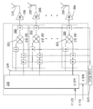
도 11 및 도 12의 시스템에서 사용될 수 있는 예시적인 능동 안테나 어레이 시스템의 내부 구조의 상세들이 도 13, 도 14 및 도 15에 제시되어 있다. 도면들은 능동 안테나 어레이 시스템을 구현하는 많은 상이한 가능한 방법들의 단지 일례를 도시한 것임을 이해해야 한다. Details of the internal structure of an exemplary active antenna array system that can be used in the systems of Figs. 11 and 12 are shown in Figs. 13, 14 and 15. Fig. It should be understood that the figures illustrate only one example of many different possible ways of implementing an active antenna array system.
설명된 실시 예에서, 안테나 어레이는 M 개의 안테나 엘리먼트들의 1 차원 또는 2 차원 어레이를 포함한다. 도 13은 다중 엘리먼트 안테나 어레이의 단일 안테나 엘리먼트(210)에 접속되는 회로의 블록도를 도시한다. M 개의 안테나 엘리먼트들을 갖는 안테나 어레이 시스템에서, 이 회로는 각 안테나 엘리먼트마다 복제된다. 각각의 안테나 엘리먼트(210)에는, 안테나 엘리먼트(210)에 접속된 프론트 엔드 모듈(또는 Tx/Rx 모듈)(200)이 있다. 프론트-엔드 모듈은 송신기 측 및 수신기 측을 갖는다. 송신기 측은 N 개의 상향 변환 모듈(202), 결합기 회로(204) 및 전력 증폭기(PA)(206)를 포함한다. 수신기 측은 저잡음 증폭기(LNA)(212), 스플리터(214), 및 N 개의 하향 변환 모듈들(216)을 포함한다. 프론트-엔드 모듈(200)은 송신기 측의 PA(206)로부터의 구동 신호를 안테나 엘리먼트(210)에 결합시키고 수신기 측의 안테나 엘리먼트(210)로부터 수신된 신호를 LNA(212)에 결합하는 듀플렉서 회로(208)를 포함한다. 각각의 상향 변환 모듈(202)의 입력은 기저 대역 유닛(미도시)으로부터 상이한 빔 송신 신호 스트림(Bt1 ... Btn)을 수신하기 위한 것이다. 각각의 하향 변환 모듈(216)의 출력은 상이한 빔 수신된 신호 스트림(Br1 ... Brn)을 출력하기 위한 것이다. 전형적으로, 각각의 빔 송신 신호 스트림은 능동 안테나 어레이 시스템에 의해 생성된 상이한 빔에 맵핑되고, 각각의 수신된 신호 스트림은 능동 안테나 어레이에 의해 형성된 상이한 수신된 빔에 의해 수신된 신호에 대응한다. In the described embodiment, the antenna array comprises a one-dimensional or two-dimensional array of M antenna elements. 13 shows a block diagram of a circuit connected to a
상향 변환 모듈(202)이 보다 상세히 도시된 능동 안테나 어레이 시스템이 도 14에 도시된다; 하향 변환 모듈(216)이 보다 상세하게 도시된 능동 안테나 어레이 시스템이 도 15에 도시된다. 실제 문제로서, 별개로 도시된, 이들 2 개의 시스템은 동일한 능동 안테나 어레이 시스템에서 구현될 것이지만, 도면을 단순화하기 위해, 여기서는 개별적으로 제시된다. 도 14의 능동 안테나 어레이 시스템은 안테나 어레이의 M개의 엘리먼트들(210)에 의해 생성된 단일 송신 빔을 통해 하나의 송신 신호 스트림을 송신하기 위한 시스템이다. 각각의 안테나 엘리먼트(210)에 대해 하나의 상향 변환 모듈(202)만이 있기 때문에, 도 13에 도시된, 결합기(204)는 필요하지 않으므로 생략되었다. 유사하게, 도 15의 능동 안테나 어레이 시스템은 안테나 어레이에 의해 생성된 단일 수신 빔 패턴상의 신호 스트림을 수신하기 위한 것이다. 각각의 안테나 엘리먼트(210)에 대해 오직 하나의 하향 변환 모듈(216)이 있기 때문에, 도 13에 도시된, 스플리터(214)는 필요하지 않으므로 생략되었다. An active antenna array system in which the up-
코히런트 또는 위상 동기화된 LO 신호를 M 개의 상향 변환 모듈(202) 및 M 개의 하향 변환 모듈(216)에 분배하기 위한 LO 분배 네트워크(220)가 있다. 도 14에 도시된 바와 같이, IF 송신 신호를 각각의 상향 변환 모듈(202)에 전달하기 위한 IF 분배 네트워크(224)가 또한 존재한다. 그리고, 도 15에 도시된 바와 같이, 하향 변환 모듈들(216) 각각으로부터 수신된 신호들을 어그리게이팅하기 위한 IF 어그리게이션 네트워크(226)가 있다. There is an
분포 및 어그리게이션 네트워크들은 신호들의 코히어런트 분포/어그리게이션을 보장하기 위해 전기적으로 동일한 경로들을 갖는 수동 선형 상호 네트워크일 수 있다. 대안적으로, 하나 이상의 이들 네트워크는 2008 년 7 월 21 일자로 출원된 "Method and System for Multi-Point Signal Generation with Phase Synchronized Local Carriers"이라는 명칭의 미국 특허 제 8,259,884 호 및 2011 년 6 월 30 일 출원된 " Low Cost, Active Antenna Arrays"라는 명칭의 미국 특허 제 8,622,959 호에 개시된 양방향 신호 네트워크를 사용하여 구현될 수 있거나 또는 2016 년 9 월 8 일자로 출원된 "Calibrating a Serial Interconnection"라는 명칭의 미국 특허 USSN15/259,639에 개시된 직렬 상호접속 접근법을 사용하여 구현될 수 있다. Distribution and aggregation networks may be passive linear interconnect networks with electrically identical paths to ensure coherent distribution / aggregation of signals. Alternatively, one or more of these networks may be used as described in U.S. Patent No. 8,259,884, entitled " Method and System for Multi-Point Signal Synchronization with Phase Synchronized Local Carriers, " filed on July 21, 2008, Which may be implemented using a bi-directional signal network as disclosed in U.S. Patent No. 8,622,959 entitled " Low Cost, Active Antenna Arrays ", or may be implemented in the United States Patent of "Calibrating a Serial Interconnection" filed September 8, May be implemented using a serial interconnection approach disclosed in USSN 15 / 259,639.
각각의 상향 변환 모듈(202)은 혼합기(203) 및 각각 A 및 P로 표시되는 다양한 진폭 및 위상 설정 회로들을 포함한다. LO 신호 및 분배된 IF 송신 신호 스트림은 모두 IF 송신 신호 스트림을 전력 증폭기(206)에 제공되는 RF 송신 신호 스트림으로 상향 변환하는 혼합기(203)에 제공된다. 유사하게, 각각의 하향 변환 모듈(216)은 혼합기(217) 및 A 및 P로 각각 식별되는 다양한 진폭 및 위상 설정 회로를 또한 포함한다. 하향 변환 모듈(216)의 혼합기(217)는 LO 분배 네트워크(220)에 의해 제공된 LO 신호와 안테나 엘리먼트(210)에 결합된 저잡음 증폭기(212)로부터 수신된 RF 신호 스트림을 곱하여 하향 변환된 IF 수신 신호 스트림을 생성한다. 하향 변환된 IF 신호 스트림은 다른 안테나 엘리먼트들로부터의 IF 수신된 신호 스트림들과의 어그리게이션과 기지국으로의 송신을 위해 IF 어그리게이션 네트워크(226)에 제공된다. Each up
진폭 및 위상 설정 회로들(A 및 P)는 개별 안테나 신호들의 상대 위상 또는 진폭을 변경하여 안테나 어레이에 의해 생성된 송신 및 수신 빔 패턴들의 크기, 방향 및 강도를 설정하기 위해 사용된다. (주 : 안테나 어레이에서, 송신 빔은 안테나 어레이에 의해 생성된 방사 패턴이다. 그 방사 패턴은 안테나 어레이의 전방에서 측정될 수 있다. 대조적으로, 수신 빔은 안테나 어레이에 의해 형성된 방사 패턴이 아니라 오히려 안테나 감도의 패턴이다. 그럼에도 불구하고, 이 차이에도 불구하고, 양자는 일반적으로 빔이라고 불린다.) 진폭 설정 회로는, 입력 신호 진폭에 대한 출력 신호 진폭의 비율이 프로그램 가능하고 전자 제어로 설정되는, 가변 이득 증폭기와 기본적으로 동일하다. 위상 설정 회로는 전자 제어 하에서 입력 신호를 위상(또는 시간)으로 시프트하는 기본 기능을 갖는다. 이들 진폭 및 위상 설정 회로는 개별 제어 프로세서(213)에 의해 공급된 디지털 제어 신호에 의해 제어된다. Amplitude and phase setting circuits A and P are used to change the relative phase or amplitude of the individual antenna signals to set the magnitude, direction and intensity of the transmit and receive beam patterns generated by the antenna array. (Note: In an antenna array, the transmit beam is a radiation pattern produced by the antenna array.) The radiation pattern may be measured in front of the antenna array. The amplitude setting circuit is a circuit in which the ratio of the output signal amplitude to the input signal amplitude is programmable and is set to electronic control, It is basically the same as a variable gain amplifier. The phase setting circuit has a basic function of shifting the input signal to phase (or time) under electronic control. These amplitude and phase setting circuits are controlled by a digital control signal supplied by an
도 14 및 도 15에 도시된 진폭 설정 및 위상 설정 회로들의 유형은 기본 송신기 및 수신기에 개별 안테나 신호의 진폭 및 위상 값을 독립적으로 제어하는 능력을 부여하는 많은 가능성 중 하나일 뿐이다. 진폭 및 위상 설정 회로의 수 및 배치는 도 14 및 도 15에 도시된 것과 변경될 수 있다. 또한, 상향 변환 및 하향 변환 모듈들에는 존재하지만 당업자에게 잘 알려져 있기 때문에 도면에 도시되지 않은 다른 컴포넌트들이 있다. 이들은, 예를 들면, 채널 IF 필터들 및 자동 이득 제어들을 포함할 수 있다. The types of amplitude setting and phase setting circuits shown in Figures 14 and 15 are only one of many possibilities to give the base transmitter and receiver the ability to independently control the amplitude and phase values of the individual antenna signals. The number and arrangement of the amplitude and phase setting circuits can be changed to those shown in Figs. 14 and 15. Fig. There are also other components that are present in the up-conversion and down-conversion modules, but are not shown in the figures because they are well known to those skilled in the art. These may include, for example, channel IF filters and automatic gain controls.
전술한 설명에서, n은 무선 헤드에 제공되는 송신 신호 스트림들의 수이고, m은 위상 어레이에 의해 생성된 빔들의 수이며, 동일할 필요는 없다는 것을 이해해야 한다. In the above description, it should be understood that n is the number of transmit signal streams provided to the wireless head, m is the number of beams generated by the phased array, and need not be the same.
전술한 가장 일반적인 경우, 행렬 곱셈을 구현하는 프로세서로부터의 각각의 출력 신호 스트림은 다중 입력 스트림의 선형 조합이다. 그러나, 반드시 그럴 필요는 없다. 출력 스트림들 중 오직 하나만이 하나보다 많은 입력 스트림의 서브세트의 선형 조합이고 나머지 모든 출력 스트림은 입력 스트림의 선형 조합이 아니지만 단순히 입력 스트림과 출력 스트림의 일대일 맵핑들일 수 있다. 또한, 이들 두 극단들(extremes) 사이의 임의의 경우도 본 발명의 범위 내에 있다는 것을 이해해야 한다. 또한, 모든 가중치(Mij)는 1과 동일할 수 있고, 이 경우 신호 스트림들의 가중된 합계는 신호 스트림들의 간단한 합계이다. In the most general case described above, each output signal stream from the processor implementing the matrix multiplication is a linear combination of multiple input streams. However, it is not necessary. Only one of the output streams is a linear combination of a subset of more than one input stream and all the remaining output streams are not linear combinations of the input streams but may simply be one-to-one mappings of the input and output streams. It is also to be understood that any instance between these two extremes is within the scope of the present invention. In addition, all weights Mij may be equal to one, in which case the weighted sum of the signal streams is a simple sum of the signal streams.
다양한 기능들이 프로세서에 의해 구현되는 실시 예에서, 프로세서는 하나 이상의 프로세서 또는 마이크로 프로세서, 하나 이상의 FPGA 또는 다른 프로그래머블 디바이스들일 수 있으며, 프로그래밍 코드 또는 명령들은 컴퓨터 판독 가능한 비휘발성 저장매체(예를 들어, EEPROM, 자기 디스크, RAM 등)에 저장될 수 있다. In embodiments where various functions are implemented by a processor, the processor may be one or more processors or microprocessors, one or more FPGAs or other programmable devices, and the programming code or instructions may be stored in a computer readable nonvolatile storage medium (e.g., an EEPROM , Magnetic disk, RAM, etc.).
다른 실시 예들은 다음의 청구 범위 내에 있다. 예를 들어, 수신기 또는 송신기의 신호 경로를 따라 IF로 변환하는 대신에, 신호는 모두 RF에서 처리될 수 있다. 따라서, 송신 측에서, 기저 대역 유닛으로부터의 디지털 신호는 IF 대신에 RF로 변환되거나 기저 대역 유닛으로부터의 RF 신호는 RF 신호로 남아있게 된다. 유사하게, 수신 측에서, 수신된 RF 신호들은 RF 신호들로 남아있을 수 있다. 또한, 행렬 곱셈 단계들은 상기 예시된 위치(예를 들어 능동 안테나 어레이 시스템(114) 내의) 이외의 신호 경로를 따라 상이한 위치(또는 심지어 다수의 위치)에서 수행될 수 있다. 또한, 여기에 기술된 신호 스트림들의 조합들은 선형 조합들이지만, 비선형 조합들과 같은 다중 신호 스트림들의 다른 유형의 조합들이 가능하다. Other embodiments are within the scope of the following claims. For example, instead of converting to an IF along the signal path of the receiver or transmitter, the signals can all be processed in RF. Thus, on the transmit side, the digital signal from the baseband unit is converted to RF instead of IF, or the RF signal from the baseband unit remains as an RF signal. Similarly, at the receiving end, the received RF signals may remain as RF signals. In addition, matrix multiplication steps may be performed at different locations (or even at multiple locations) along the signal path other than the above-exemplified location (e.g., within the active antenna array system 114). Also, combinations of signal streams described herein are linear combinations, but other types of combinations of multiple signal streams, such as non-linear combinations, are possible.
Claims (41)
상기 복수의 송신 신호 스트림들을 복수의 개별 빔 신호 스트림들에 맵핑하는 단계 - 상기 복수의 빔 신호 스트림들 중 적어도 하나의 빔 신호 스트림들은 상기 복수의 송신 신호 스트림들의 다중 송신 신호 스트림들의 조합임 - ;
복수의 송신 빔들을 생성하기 위해 상기 안테나 어레이를 사용하는 단계; 및
상기 복수의 송신 빔들 중 상이한 송신 빔을 통해 상기 복수의 빔 신호 스트림들의 각각의 빔 신호 스트림을 송신하는 단계를 포함하는, 안테나 어레이를 포함하는 방법.CLAIMS What is claimed is: 1. A method comprising: an antenna array for wirelessly transmitting information carried by a source signal stream comprising a plurality of individual transmit signal streams, the method comprising:
Mapping the plurality of transmit signal streams to a plurality of separate beam signal streams, wherein at least one of the plurality of beam signal streams is a combination of multiple transmit signal streams of the plurality of transmit signal streams;
Using the antenna array to generate a plurality of transmit beams; And
And transmitting each beam signal stream of the plurality of beam signal streams over a different one of the plurality of transmission beams.

여기서, 상기 Txi(i=1…n이고, n은 정수임)는 상기 복수의 송신 신호 스트림들이고, TBj(j=1…m이고, m은 정수임)는 상기 복수의 빔 신호 스트림들이고, 상기 Mji(i=1…n이고, j=1…m임)는 가중치인, 안테나 어레이를 포함하는 방법.10. The method of claim 9, wherein the matrix multiplication operation comprises:
(M = 1, ..., m, m) are the plurality of beam signal streams, and the Mji (i = 1 ... n, n is an integer) are the plurality of transmission signal streams, i = 1 ... n, j = 1 ... m) is a weight.
다중 안테나 엘리먼트들 및 복수의 입력들을 갖는 안테나 어레이 시스템;
상기 안테나 어레이 시스템을 제어하고 상기 안테나 어레이 시스템으로 하여금 복수의 송신 빔들을 생성하도록 구성되는 제어기 - 상기 복수의 송신 빔들의 각각의 송신 빔은 상기 안테나 어레이 시스템의 복수의 입력들의 상이한 입력에 대응함 - ; 및
각각의 출력이 안테나 어레이 시스템의 대응하는 상이한 입력에 전기적으로 결합되는 복수의 출력을 갖는 신호 맵핑 모듈 - 상기 신호 맵핑 모듈은 상기 복수의 송신 신호 스트림들을 복수의 개별 빔 신호 스트림들에 맵핑하도록 구성되고, 복수의 개별 빔 신호 스트림들의 각각이 상기 신호 맵핑 모듈의 복수의 출력들의 대응하는 상이한 출력 상에 제공되고, 상기 복수의 빔 신호 스트림들 중 적어도 하나의 빔 신호 스트림들은 상기 복수의 송신 신호 스트림들의 다중 송신 신호 스트림들의 조합임 - 를 포함하는, 안테나 시스템.An antenna system for wirelessly transmitting information carried by a source signal stream comprising a plurality of discrete transmit signal streams, the system comprising:
An antenna array system having multiple antenna elements and a plurality of inputs;
A controller configured to control the antenna array system and to cause the antenna array system to generate a plurality of transmit beams, wherein each transmit beam of the plurality of transmit beams corresponds to a different input of a plurality of inputs of the antenna array system; And
A signal mapping module having a plurality of outputs, each output electrically coupled to a corresponding different input of the antenna array system, the signal mapping module being configured to map the plurality of transmit signal streams to a plurality of separate beam signal streams Wherein each of a plurality of individual beam signal streams is provided on a corresponding different output of a plurality of outputs of the signal mapping module and wherein at least one of the plurality of beam signal streams comprises a plurality of transmit signal streams, A combination of multiple transmit signal streams.

여기서, 상기 TBi(i=1…m이고, m은 정수임)는 상기 복수의 송신 신호 스트림들이고, Txj(j=1…n이고, n은 정수임)는 상기 복수의 빔 신호 스트림들이고, 상기 Mij(i=1…m이고, j=1…n임)는 가중치인, 안테나 시스템.23. The method of claim 22, wherein the matrix multiplication operation comprises:
(J = 1 ... n, where n is an integer) are the plurality of beam signal streams, and Mij (i = 1, i = 1 ... m, j = 1 ... n) is a weight.
복수의 수신 빔들을 생성하기 위해 상기 안테나 어레이를 사용하는 단계;
상기 복수의 수신 빔들을 통해 복수의 빔 신호 스트림들을 수신하는 단계 - 상기 복수의 빔 신호 스트림들의 각각의 빔 신호 스트림은 상기 복수의 수신 빔들의 상이한 대응하는 수신 빔을 통해 수신됨 - ; 및
상기 복수의 빔 신호 스트림들을 복수의 개별 수신된 신호 스트림들에 맵핑하는 단계 - 상기 복수의 수신된 신호 스트림들 중 적어도 하나의 수신된 신호 스트림들은 상기 복수의 빔 신호 스트림들의 다중 빔 신호 스트림들의 조합임 - 를 포함하는, 안테나 어레이를 포함하는 방법.A method comprising an antenna array, the method comprising:
Using the antenna array to generate a plurality of receive beams;
Receiving a plurality of beam signal streams through the plurality of receive beams, wherein each beam signal stream of the plurality of beam signal streams is received via a different corresponding receive beam of the plurality of receive beams; And
Mapping the plurality of beam signal streams to a plurality of individually received signal streams, wherein at least one received signal streams of the plurality of received signal streams comprise a combination of multiple beam signal streams of the plurality of beam signal streams, And an antenna array.

여기서, 상기 Rxi(i=1…n이고, n은 정수임)는 상기 복수의 수신된 신호 스트림들이고, RBj(j=1…m이고, m은 정수임)는 상기 복수의 빔 신호 스트림들이고, 상기 Lji(i=1…n이고, j=1…m임)는 가중치인, 안테나 어레이를 포함하는 방법.35. The method of claim 34, wherein the matrix multiplication operation comprises:
Wherein m is an integer, and Rxj is the plurality of received signal streams, RBj (where j = 1 ... m and m is an integer) are the plurality of beam signal streams, and Lji (where i = 1 ... n and j = 1 ... m) is a weight.
다중 안테나 엘리먼트들을 갖는 안테나 어레이 시스템;
안테나 어레이 시스템을 제어하고 안테나 어레이 시스템으로 하여금 복수의 빔 신호 스트림들을 수신하기 위한 복수의 수신 빔들을 생성하도록 구성되는 제어기 - 상기 복수의 수신 빔들의 각각은 상기 복수의 빔 신호 스트림들의 대응하는 빔 신호 스트림을 생성하기 위한 것임 - ; 및
상기 안테나 어레이 시스템에 전기적으로 결합되고 복수의 출력들을 갖는 신호 맵핑 모듈 - 상기 신호 맵핑 모듈은 상기 복수의 수신 신호 스트림들을 복수의 개별 수신된 신호 스트림들에 맵핑하도록 구성되고, 복수의 개별 수신된 신호 스트림들의 각각이 상기 신호 맵핑 모듈의 복수의 출력들의 대응하는 상이한 출력 상에 제공되고, 상기 복수의 수신된 신호 스트림들 중 적어도 하나의 수신된 신호 스트림들은 상기 복수의 빔 신호 스트림들의 다중 빔 신호 스트림들의 조합임 - 를 포함하는, 안테나 시스템.An antenna system,
An antenna array system having multiple antenna elements;
A controller configured to control an antenna array system and to cause an antenna array system to generate a plurality of receive beams for receiving a plurality of beam signal streams, each of the plurality of receive beams including a corresponding beam signal of the plurality of beam signal streams To generate a stream; And
A signal mapping module electrically coupled to the antenna array system and having a plurality of outputs, the signal mapping module being configured to map the plurality of received signal streams to a plurality of individually received signal streams, Each of the streams being provided on a corresponding different output of the plurality of outputs of the signal mapping module and wherein at least one of the plurality of received signal streams comprises a plurality of beam signal streams of the plurality of beam signal streams, The antenna system comprising:

여기서, 상기 Rxi(i=1…n이고, n은 정수임)는 상기 복수의 수신된 신호 스트림들이고, RBj(j=1…m이고, m은 정수임)는 상기 복수의 빔 신호 스트림들이고, 상기 Lij(i=1…n이고, j=1…m임)는 가중치인, 안테나 시스템.The method of claim 37, wherein the matrix multiplication operation further comprises:
(J = 1 ... m, where m is an integer) is the plurality of beam signal streams, and Lij (j = 1 ... m and m is an integer) are the plurality of received signal streams, (where i = 1 ... n and j = 1 ... m) is a weight.
Applications Claiming Priority (3)
| Application Number | Priority Date | Filing Date | Title |
|---|---|---|---|
| US201662276311P | 2016-01-08 | 2016-01-08 | |
| US62/276,311 | 2016-01-08 | ||
| PCT/US2017/012428 WO2017120403A1 (en) | 2016-01-08 | 2017-01-06 | Antenna mapping and diversity |
Publications (1)
| Publication Number | Publication Date |
|---|---|
| KR20180102612A true KR20180102612A (en) | 2018-09-17 |
Family
ID=57868393
Family Applications (1)
| Application Number | Title | Priority Date | Filing Date |
|---|---|---|---|
| KR1020187022809A KR20180102612A (en) | 2016-01-08 | 2017-01-06 | Antenna mapping and diversity |
Country Status (7)
| Country | Link |
|---|---|
| US (1) | US10700755B2 (en) |
| EP (1) | EP3400656B1 (en) |
| JP (1) | JP2019507527A (en) |
| KR (1) | KR20180102612A (en) |
| CN (1) | CN108702195B (en) |
| CA (1) | CA3010775A1 (en) |
| WO (1) | WO2017120403A1 (en) |
Cited By (3)
| Publication number | Priority date | Publication date | Assignee | Title |
|---|---|---|---|---|
| KR20220024039A (en) | 2019-06-20 | 2022-03-03 | 유니챰 가부시키가이샤 | Pants-type absorbent article |
| KR20220024073A (en) | 2019-06-20 | 2022-03-03 | 유니챰 가부시키가이샤 | absorbent article |
| KR20220163382A (en) | 2020-04-06 | 2022-12-09 | 유니챰 가부시키가이샤 | Pants-type absorbent article |
Families Citing this family (6)
| Publication number | Priority date | Publication date | Assignee | Title |
|---|---|---|---|---|
| KR102306128B1 (en) * | 2015-06-04 | 2021-09-28 | 한국전자통신연구원 | Method and apparatus for configuring virtual beam identifier, and method and apparatus for allocating resource using the virtual beam identifier |
| EP3400656B1 (en) * | 2016-01-08 | 2022-07-20 | Blue Danube Systems, Inc. | Antenna mapping and diversity |
| US20180150256A1 (en) | 2016-11-29 | 2018-05-31 | Intel Corporation | Technologies for data deduplication in disaggregated architectures |
| US11133575B2 (en) * | 2017-12-11 | 2021-09-28 | Commscope Technologies Llc | Small cell base stations with strand-mounted antennas |
| US10826570B2 (en) | 2018-05-31 | 2020-11-03 | Skyworks Solutions, Inc. | Apparatus and methods for multi-antenna communications |
| KR102400999B1 (en) * | 2018-12-27 | 2022-05-23 | 삼성전자주식회사 | Method and apparatus for combining a plurality of radio frequency signals |
Family Cites Families (23)
| Publication number | Priority date | Publication date | Assignee | Title |
|---|---|---|---|---|
| JPH06244766A (en) * | 1993-02-19 | 1994-09-02 | Mitsubishi Electric Corp | Radio carrier communication equipment for mobile expansion |
| US6968022B1 (en) * | 1999-09-23 | 2005-11-22 | Princeton University | Method and apparatus for scheduling switched multibeam antennas in a multiple access environment |
| CA2466922A1 (en) * | 2001-11-09 | 2003-05-15 | Ems Technologies, Inc. | Beamformer for multi-beam broadcast antenna |
| US6856284B1 (en) * | 2003-10-22 | 2005-02-15 | Itt Manufacturing Enterprises, Inc. | Methods and apparatus for multi-beam, multi-signal transmission for active phased array antenna |
| US8031117B2 (en) * | 2004-09-23 | 2011-10-04 | Interdigital Technology Corporation | Blind signal separation using polarized antenna elements |
| WO2006133225A2 (en) * | 2005-06-06 | 2006-12-14 | Multigig Inc. | True time delay phase array radar using rotary clocks and electronic delay lines |
| JP4356756B2 (en) * | 2006-04-27 | 2009-11-04 | ソニー株式会社 | Wireless communication system, wireless communication apparatus, and wireless communication method |
| US20100259433A1 (en) * | 2007-05-10 | 2010-10-14 | Astrium Limited | Signal Processing System |
| EP2854326A1 (en) | 2007-07-20 | 2015-04-01 | Blue Danube Labs Inc | Method and system for multi-point signal generation with phase synchronized local carriers |
| WO2010043752A1 (en) * | 2008-10-16 | 2010-04-22 | Elektrobit Wireless Communications Oy | Beam forming method, apparatus and system |
| TR201807974T4 (en) | 2010-07-01 | 2018-06-21 | Blue Danube Systems Inc | Cost effective, active antenna arrays. |
| US9036475B2 (en) * | 2010-12-22 | 2015-05-19 | Telefonaktiebolaget L M Ericsson (Publ) | Method and arrangement in a distributed radio base station |
| US20120281555A1 (en) * | 2011-05-02 | 2012-11-08 | Research In Motion Limited | Systems and Methods of Wireless Communication with Remote Radio Heads |
| KR20130127347A (en) | 2012-05-10 | 2013-11-22 | 삼성전자주식회사 | Method and apparatus for communication on analog and digital hybrid beam-forming |
| US8861635B2 (en) * | 2012-05-29 | 2014-10-14 | Magnolia Broadband Inc. | Setting radio frequency (RF) beamformer antenna weights per data-stream in a multiple-input-multiple-output (MIMO) system |
| US9568589B1 (en) * | 2012-09-05 | 2017-02-14 | Rkf Engineering Solutions Llc | Satellite beamforming and channelization |
| US20140334564A1 (en) * | 2013-05-09 | 2014-11-13 | Samsung Electronics Co., Ltd | Method and system for providing low-complexity hybrid precoding in wireless communication systems |
| US9806926B2 (en) * | 2013-11-04 | 2017-10-31 | Samsung Electronics Co., Ltd. | Multistage beamforming of multiple-antenna communication system |
| WO2015115776A1 (en) | 2014-01-28 | 2015-08-06 | Samsung Electronics Co., Ltd. | Multistage beamforming of multiple-antenna communication system |
| EP3091681B1 (en) * | 2014-04-02 | 2019-11-06 | Huawei Technologies Co. Ltd. | Beamforming-based communication method and apparatus |
| AU2014399819B2 (en) * | 2014-06-09 | 2018-03-15 | Huawei Technologies Co., Ltd. | Antenna port mapping method and apparatus |
| US9762301B2 (en) * | 2015-07-24 | 2017-09-12 | Electronics And Telecommunications Research Institute | Base station and terminal for distributed array massive multiple-input and multiple-output (MIMO) communication antenna system |
| EP3400656B1 (en) * | 2016-01-08 | 2022-07-20 | Blue Danube Systems, Inc. | Antenna mapping and diversity |
-
2017
- 2017-01-06 EP EP17701219.2A patent/EP3400656B1/en active Active
- 2017-01-06 CA CA3010775A patent/CA3010775A1/en active Pending
- 2017-01-06 JP JP2018535406A patent/JP2019507527A/en active Pending
- 2017-01-06 CN CN201780016033.7A patent/CN108702195B/en active Active
- 2017-01-06 US US15/399,833 patent/US10700755B2/en active Active
- 2017-01-06 KR KR1020187022809A patent/KR20180102612A/en not_active Application Discontinuation
- 2017-01-06 WO PCT/US2017/012428 patent/WO2017120403A1/en active Application Filing
Cited By (3)
| Publication number | Priority date | Publication date | Assignee | Title |
|---|---|---|---|---|
| KR20220024039A (en) | 2019-06-20 | 2022-03-03 | 유니챰 가부시키가이샤 | Pants-type absorbent article |
| KR20220024073A (en) | 2019-06-20 | 2022-03-03 | 유니챰 가부시키가이샤 | absorbent article |
| KR20220163382A (en) | 2020-04-06 | 2022-12-09 | 유니챰 가부시키가이샤 | Pants-type absorbent article |
Also Published As
| Publication number | Publication date |
|---|---|
| EP3400656B1 (en) | 2022-07-20 |
| CA3010775A1 (en) | 2017-07-13 |
| WO2017120403A1 (en) | 2017-07-13 |
| EP3400656A1 (en) | 2018-11-14 |
| US10700755B2 (en) | 2020-06-30 |
| US20170201310A1 (en) | 2017-07-13 |
| CN108702195A (en) | 2018-10-23 |
| JP2019507527A (en) | 2019-03-14 |
| CN108702195B (en) | 2021-11-09 |
Similar Documents
| Publication | Publication Date | Title |
|---|---|---|
| CN108702195B (en) | Antenna mapping and diversity | |
| US10771123B2 (en) | Distributed phased arrays based MIMO (DPA-MIMO) for next generation wireless user equipment hardware design and method | |
| CN108432153B (en) | Method and apparatus for controlling equivalent omni-directional radiated power | |
| EP2514034B1 (en) | Communication unit, integrated circuit and method of diverse polarisation | |
| EP2865105B1 (en) | Full-duplex wireless communication system using polarization | |
| US11728879B2 (en) | Dual-polarization beamforming | |
| US10020866B2 (en) | Wireless communication node with adaptive communication | |
| US10374670B2 (en) | Port-to-beam precoding to enable codebook based MU-MIMO operation in active antenna systems | |
| CN110915148B (en) | Antenna arrangement and method for beamforming | |
| US9240813B2 (en) | Distributed digitally convertible radio (DDCR) | |
| EP3130038B1 (en) | Antenna arrangement | |
| WO2019178464A1 (en) | Digital port expansion for hybrid massive mimo systems | |
| CN115189745A (en) | Signal forwarding method and device | |
| WO2017143133A1 (en) | Synthesizing cross-polarized beams with a phased array | |
| WO2023191673A1 (en) | Method and network node for handling a phased array antenna module of a network node of a wireless communication network |
Legal Events
| Date | Code | Title | Description |
|---|---|---|---|
| A201 | Request for examination | ||
| E902 | Notification of reason for refusal | ||
| E601 | Decision to refuse application |