KR20180098443A - Method and apparatus for recognizing finger print - Google Patents
Method and apparatus for recognizing finger print Download PDFInfo
- Publication number
- KR20180098443A KR20180098443A KR1020170024883A KR20170024883A KR20180098443A KR 20180098443 A KR20180098443 A KR 20180098443A KR 1020170024883 A KR1020170024883 A KR 1020170024883A KR 20170024883 A KR20170024883 A KR 20170024883A KR 20180098443 A KR20180098443 A KR 20180098443A
- Authority
- KR
- South Korea
- Prior art keywords
- fingerprint
- fingerprint image
- image
- control unit
- registered
- Prior art date
Links
- 238000000034 method Methods 0.000 title claims description 61
- 238000012545 processing Methods 0.000 claims description 23
- 238000012937 correction Methods 0.000 claims description 17
- 238000012935 Averaging Methods 0.000 claims description 10
- 230000008569 process Effects 0.000 description 11
- 238000011156 evaluation Methods 0.000 description 6
- 230000002093 peripheral effect Effects 0.000 description 6
- 210000003462 vein Anatomy 0.000 description 6
- 208000016339 iris pattern Diseases 0.000 description 5
- 210000004204 blood vessel Anatomy 0.000 description 3
- 230000008859 change Effects 0.000 description 3
- 238000010586 diagram Methods 0.000 description 3
- 239000013598 vector Substances 0.000 description 3
- 238000003491 array Methods 0.000 description 2
- 230000006870 function Effects 0.000 description 2
- 210000000554 iris Anatomy 0.000 description 2
- 230000003287 optical effect Effects 0.000 description 2
- 101100219325 Phaseolus vulgaris BA13 gene Proteins 0.000 description 1
- 230000008901 benefit Effects 0.000 description 1
- 238000004891 communication Methods 0.000 description 1
- 238000004590 computer program Methods 0.000 description 1
- 230000007423 decrease Effects 0.000 description 1
- 238000011161 development Methods 0.000 description 1
- 238000005516 engineering process Methods 0.000 description 1
- 210000000887 face Anatomy 0.000 description 1
- 238000005286 illumination Methods 0.000 description 1
- 238000002156 mixing Methods 0.000 description 1
- 238000003672 processing method Methods 0.000 description 1
- 210000001747 pupil Anatomy 0.000 description 1
- 230000004044 response Effects 0.000 description 1
- 210000003786 sclera Anatomy 0.000 description 1
- 238000013519 translation Methods 0.000 description 1
- 238000012795 verification Methods 0.000 description 1
Images


Classifications
-
- G—PHYSICS
- G06—COMPUTING; CALCULATING OR COUNTING
- G06F—ELECTRIC DIGITAL DATA PROCESSING
- G06F21/00—Security arrangements for protecting computers, components thereof, programs or data against unauthorised activity
- G06F21/30—Authentication, i.e. establishing the identity or authorisation of security principals
- G06F21/31—User authentication
- G06F21/32—User authentication using biometric data, e.g. fingerprints, iris scans or voiceprints
-
- G—PHYSICS
- G06—COMPUTING; CALCULATING OR COUNTING
- G06F—ELECTRIC DIGITAL DATA PROCESSING
- G06F21/00—Security arrangements for protecting computers, components thereof, programs or data against unauthorised activity
- G06F21/30—Authentication, i.e. establishing the identity or authorisation of security principals
- G06F21/45—Structures or tools for the administration of authentication
-
- G06K9/00006—
-
- G06K9/4609—
-
- G—PHYSICS
- G06—COMPUTING; CALCULATING OR COUNTING
- G06V—IMAGE OR VIDEO RECOGNITION OR UNDERSTANDING
- G06V10/00—Arrangements for image or video recognition or understanding
- G06V10/40—Extraction of image or video features
- G06V10/44—Local feature extraction by analysis of parts of the pattern, e.g. by detecting edges, contours, loops, corners, strokes or intersections; Connectivity analysis, e.g. of connected components
- G06V10/443—Local feature extraction by analysis of parts of the pattern, e.g. by detecting edges, contours, loops, corners, strokes or intersections; Connectivity analysis, e.g. of connected components by matching or filtering
-
- G—PHYSICS
- G06—COMPUTING; CALCULATING OR COUNTING
- G06V—IMAGE OR VIDEO RECOGNITION OR UNDERSTANDING
- G06V40/00—Recognition of biometric, human-related or animal-related patterns in image or video data
- G06V40/10—Human or animal bodies, e.g. vehicle occupants or pedestrians; Body parts, e.g. hands
- G06V40/12—Fingerprints or palmprints
- G06V40/1347—Preprocessing; Feature extraction
- G06V40/1359—Extracting features related to ridge properties; Determining the fingerprint type, e.g. whorl or loop
-
- G—PHYSICS
- G06—COMPUTING; CALCULATING OR COUNTING
- G06V—IMAGE OR VIDEO RECOGNITION OR UNDERSTANDING
- G06V40/00—Recognition of biometric, human-related or animal-related patterns in image or video data
- G06V40/10—Human or animal bodies, e.g. vehicle occupants or pedestrians; Body parts, e.g. hands
- G06V40/12—Fingerprints or palmprints
- G06V40/1365—Matching; Classification
- G06V40/1376—Matching features related to ridge properties or fingerprint texture
Landscapes
- Engineering & Computer Science (AREA)
- Theoretical Computer Science (AREA)
- Physics & Mathematics (AREA)
- General Physics & Mathematics (AREA)
- Computer Security & Cryptography (AREA)
- Multimedia (AREA)
- Computer Hardware Design (AREA)
- Software Systems (AREA)
- General Engineering & Computer Science (AREA)
- Human Computer Interaction (AREA)
- Computer Vision & Pattern Recognition (AREA)
- Collating Specific Patterns (AREA)
Abstract
Description
본 개시는 지문 인식 장치 및 지문 인식 방법에 관한 것이다.The present disclosure relates to a fingerprint recognition apparatus and a fingerprint recognition method.
최근 다양한 모바일 기기 및 웨어러블(wearable) 기기의 발전에 따라, 금융, 보안 등 개인 정보가 활용되는 다양한 기능이 제공되고 있어, 보안 인증에 대한 중요성이 증대되고 있다. 2. Description of the Related Art [0002] With the recent development of various mobile devices and wearable devices, various functions utilizing personal information such as finance and security have been provided, and the importance of security authentication is increasing.
생체 인식에 의한 인증 기술은 지문, 홍채, 목소리, 얼굴, 혈관 등을 이용하여 사용자를 인증한다. 인증에 사용되는 생체 특성들은 사람마다 다르고, 소지의 불편함이 없을 뿐 아니라, 도용이나 모조의 위험성이 적고, 일생 동안 잘 변하지 않는다. Biometrics authentication technology authenticates users using fingerprints, irises, voices, faces, blood vessels, and so on. The biometric characteristics used for authentication vary from person to person, and not only do they have the inconvenience of possession, they have less risk of theft or imitation, and do not change well throughout their lives.
특히, 지문 인증 방식은 편리성, 보안성, 경제성 등의 여러 가지 이유로 점차 상용화되고 있다. 지문 인증 방식에서 사용되는 센싱부는 사용자의 손가락과 직접적으로 또는 간접적으로 접촉하여 손가락의 지문을 인식하고, 지문 패턴을 지문 이미지로서 획득할 수 있다.In particular, the fingerprint authentication method is gradually being commercialized for various reasons such as convenience, security, and economy. The sensing unit used in the fingerprint authentication method can directly or indirectly contact the user's finger to recognize the fingerprint of the finger and acquire the fingerprint pattern as the fingerprint image.
실시예들은 저해상도의 지문 이미지를 이용하여 지문 인증을 수행하는 지문 인증 장치 및 지문 인증 방법을 제공하기 위한 것이다.Embodiments provide a fingerprint authentication device and a fingerprint authentication method for performing fingerprint authentication using a fingerprint image of a low resolution.
실시예들은 여러 유형으로 획득된 지문 이미지를 이용하여 정확한 지문 인증을 수행하는 지문 인증 장치 및 지문 인증 방법을 제공하기 위한 것이다.Embodiments provide a fingerprint authentication device and a fingerprint authentication method that perform accurate fingerprint authentication using fingerprint images obtained in various types.
실시예에 따른 지문 인증 장치는 사용자의 지문으로부터 지문 이미지를 획득하는 센싱부, 등록 지문 이미지를 저장하는 메모리, 그리고 지문 이미지의 적어도 일 영역과 등록 지문 이미지 간의 상관 계수를 계산하고, 상관 계수와 임계치를 비교한 결과에 따라 지문 이미지를 미리 결정된 각도에 따라 회전 보정하는 제어부를 포함하고, 적어도 일 영역의 면적이 지문 이미지의 면적의 5% 내지 40% 범위이다.A fingerprint authentication apparatus according to an embodiment includes a sensing unit that acquires a fingerprint image from a fingerprint of a user, a memory that stores the registered fingerprint image, and a correlation coefficient calculating unit that calculates a correlation coefficient between at least one area of the fingerprint image and the registered fingerprint image, And the control unit rotates the fingerprint image according to a predetermined angle, and the area of at least one area is in the range of 5% to 40% of the area of the fingerprint image.
제어부는 위상 한정 상관법(POC: Phase only Correlation)을 이용하여, 적어도 일 영역과 등록 지문 이미지 간의 중첩 영역을 판정하고, 판정 결과를 이용하여 등록 이미지에 대한 적어도 일 영역의 위치를 보정할 수 있다.The control unit can determine the overlapping area between at least one area and the registered fingerprint image using Phase-Only Correlation (POC) and correct the position of at least one region with respect to the registered image using the determination result .
제어부는 적어도 일 영역과 등록 이미지 간의 최대 상관 계수를 갖게 하는 회전 각도 및 보정 위치를 메모리에 저장할 수 있다.The control unit may store in the memory a rotation angle and a correction position that have a maximum correlation coefficient between at least one area and the registration image.
제어부는 지문 이미지를 복수의 블록으로 분할하고, 각각의 블록 마다 휘도 편차를 산출하여, 각각의 블록의 가중치 계수를 획득할 수 있다.The control unit can divide the fingerprint image into a plurality of blocks, calculate the luminance deviation for each block, and obtain the weighting coefficient of each block.
제어부는 지문 이미지의 적어도 하나의 분기점을 지문 이미지의 특징점으로서 검출하여, 지문 이미지의 특징점이 등록 지문 이미지의 특징점과 일치하는지 여부를 판단할 수 있다.The control unit may detect at least one turning point of the fingerprint image as a feature point of the fingerprint image to determine whether the feature point of the fingerprint image matches the feature point of the registered fingerprint image.
제어부는 분기점들 사이의 거리를 검출하고, 검출된 거리를 이용하여 적어도 하나의 분기점 중 적어도 하나의 분기점을 지문 이미지의 특징점에서 제외할 수 있다.The control unit may detect a distance between the bifurcation points and exclude at least one bifurcation of the at least one bifurcation from the feature points of the fingerprint image using the detected distance.
제어부는 지문 이미지의 특징점이 등록 지문 이미지의 특징점과 일치하는지 여부를 판단할 때, 가중치 계수를 고려하여, 지문 이미지의 특징점과 등록 지문 이미지의 특징점의 일치 정도를 산출할 수 있다.The control unit can calculate the degree of coincidence between the minutiae points of the fingerprint image and the minutiae points of the registered fingerprint image in consideration of the weighting coefficient when judging whether or not the minutiae points of the fingerprint image coincide with the minutiae points of the registered fingerprint image.
센싱부가 획득한 지문 이미지는 해상도가 300dpi 미만일 수 있다.The fingerprint image acquired by the sensing unit may have a resolution of less than 300 dpi.
제어부는 지문 이미지에 대해 고해상화 처리하고, 처리된 지문 이미지를 복수의 서브 블록으로 분할하며, 각각의 서브 블록 내의 고주파 노이즈를 제거하여 조합 지문 이미지를 생성할 수 있다.The control unit may perform a high-resolution process on the fingerprint image, divide the processed fingerprint image into a plurality of subblocks, and remove the high-frequency noise in each subblock to generate a combined fingerprint image.
제어부는 처리된 이미지를 서로 상이한 원점을 기준으로 분할하여 생성된 적어도 두 개의 조합 지문 이미지를 평균화 처리할 수 있다.The control unit may averify the at least two combined fingerprint images generated by dividing the processed images based on different origin points.
실시예에 따른 지문 인증 방법은 센싱부가 사용자의 지문으로부터 지문 이미지를 획득하는 단계, 메모리에 미리 저장된 등록 지문 이미지를 판독하는 단계, 지문 이미지의 적어도 일 영역과 등록 지문 이미지 간의 상관 계수를 계산하는 단계, 그리고 상관 계수와 임계치를 비교한 결과에 따라 지문 이미지를 미리 결정된 각도에 따라 회전 보정하는 단계를 포함하고, 적어도 일 영역의 면적이 지문 이미지의 면적의 5% 내지 40% 범위이다.The fingerprint authentication method according to the embodiment includes the steps of acquiring a fingerprint image from the fingerprint of the user, reading a registered fingerprint image stored in advance in the memory, calculating a correlation coefficient between at least one area of the fingerprint image and the registered fingerprint image And correcting rotation of the fingerprint image according to a predetermined angle according to a result of comparing the correlation coefficient and the threshold value, wherein the area of at least one area is in a range of 5% to 40% of the area of the fingerprint image.
상관 계수를 계산하는 단계 이전에, 위상 한정 상관법(POC: Phase only Correlation)을 이용하여, 적어도 일 영역와 등록 지문 이미지 간의 중첩 영역을 판정하는 단계, 그리고 판정 결과를 이용하여 등록 이미지에 대한 적어도 일 영역의 위치를 보정하는 단계를 더 포함할 수 있다.Prior to calculating the correlation coefficient, determining an overlapping region between at least one region and a registered fingerprint image using phase-only correlation (POC), and determining at least one region of the registration image using the determination result And correcting the position of the area.
회전 보정 하는 단계 이후에, 적어도 일 영역과 등록 이미지 간의 최대 상관 계수를 갖게 하는 회전 각도 및 보정 위치를 메모리에 저장하는 단계를 더 포함할 수 있다.The step of correcting the rotation may further include storing a rotation angle and a correction position in the memory, the rotation angle having a maximum correlation coefficient between at least one area and the registration image.
메모리에 저장하는 단계 이후에, 지문 이미지를 복수의 블록으로 분할하는 단계, 그리고, 각각의 블록 마다 휘도 편차를 산출하여, 각각의 블록의 가중치 계수를 획득하는 단계를 더 포함할 수 있다.Dividing the fingerprint image into a plurality of blocks after the storing in the memory, and calculating a brightness deviation for each of the blocks to obtain weight coefficients of the respective blocks.
메모리에 저장하는 단계 이후에, 지문 이미지의 적어도 하나의 분기점을 지문 이미지의 특징점으로서 검출하는 단계, 그리고 지문 이미지의 특징점이 등록 지문 이미지의 특징점과 일치하는지 여부를 판단하는 단계를 더 포함할 수 있다.Detecting at least one bifurcation point of the fingerprint image as a feature point of the fingerprint image after the storing in the memory and determining whether the feature point of the fingerprint image matches the feature point of the registered fingerprint image .
지문 이미지의 적어도 하나의 분기점을 지문 이미지의 특징점으로서 검출하는 단계 이후에, 분기점들 사이의 거리를 검출하고, 검출된 거리를 이용하여 적어도 하나의 분기점 중 적어도 하나의 분기점을 지문 이미지의 특징점에서 제외하는 단계를 더 포함할 수 있다.Detecting at least one bifurcation point of the fingerprint image as a feature point of the fingerprint image, detecting a distance between the bifurcation points, and removing at least one of the at least one bifurcation point from the feature points of the fingerprint image using the detected distance The method comprising the steps of:
지문 이미지의 특징점이 등록 지문 이미지의 특징점과 일치하는지 여부를 판단하는 단계는, 가중치 계수를 고려하여, 지문 이미지의 특징점과 등록 지문 이미지의 특징점의 일치 정도를 산출하는 단계를 포함할 수 있다.The step of determining whether or not the minutiae points of the fingerprint image coincide with the minutiae points of the registered fingerprint image may include calculating a degree of matching between the minutiae points of the fingerprint image and the minutiae points of the registered fingerprint image in consideration of the weighting coefficient.
상관 계수를 계산하는 단계 이전에, 지문 이미지에 대해 고해상화 처리하는 단계, 처리된 지문 이미지를 복수의 서브 블록으로 분할하는 단계, 그리고 각각의 서브 블록 내의 고주파 노이즈를 제거하여 조합 지문 이미지를 생성하는 단계를 더 포함할 수 있다.Prior to the step of calculating the correlation coefficient, a step of high-resolution processing the fingerprint image, dividing the processed fingerprint image into a plurality of sub-blocks, and removing the high-frequency noise in each sub-block to generate a combined fingerprint image Step < / RTI >
조합 지문 이미지를 생성하는 단계 이후에, 처리된 이미지를 서로 상이한 원점을 기준으로 분할하여 생성된 적어도 두 개의 조합 지문 이미지를 평균화 처리하는 단계를 더 포함할 수 있다.And a step of averaging at least two combined fingerprint images generated by dividing the processed images based on different origin from each other after the step of generating the combined fingerprint image.
센싱부가 획득한 지문 이미지는 해상도가 300dpi 미만일 수 있다.The fingerprint image acquired by the sensing unit may have a resolution of less than 300 dpi.
실시예들에 따르면, 저해상도의 센싱부를 이용하여 지문 인증을 수행할 수 있는 장점이 있다.According to the embodiments, fingerprint authentication can be performed using a low-resolution sensing unit.
실시예들에 따르면, 신속하고 편리하게 지문 인증을 수행할 수 있는 장점이 있다.According to the embodiments, there is an advantage that fingerprint authentication can be performed quickly and conveniently.
도 1은 실시예의 지문 인증 장치를 개략적으로 나타낸 블록도(block diagram)이다.
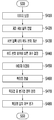
도 2는 실시예의 지문 인증 방법을 개략적으로 나타낸 순서도(flow chart)이다.
도 3은 도 2의 지문 이미지 처리 단계를 구체적으로 나타낸 순서도이다.
도 4는 도 3의 고해상화 처리의 일 예를 나타낸 예시도이다.
도 5는 도 3의 조합 이미지 생성의 일 예를 나타낸 예시도이다.
도 6은 도 3의 평균화 처리와 관련된 지문 이미지의 일 예를 나타낸 예시도이다.
도 7은 도 2의 이미지 정합(image matching) 단계를 구체적으로 나타낸 순서도이다.
도 8은 도 7에서 전체 이미지에 대한 기준 이미지의 비율 변화에 따른 이미지 정합을 나타낸 예시도이다.
도 9는 도 2의 특징점 평가 단계를 구체적으로 나타낸 순서도이다.
도 10은 도 9의 서브 블록 분할 후에 계산된 휘도 편차의 일 예를 나타낸 예시도이다.
도 11은 도 9의 특징점 진위 판정 단계를 구체적으로 나타낸 순서도이다.
도 12 및 도 13은 도 11의 방식에 따라 분기점이 특징점인지 판단하는 예들을 나타낸 예시도이다.
도 14는 도 9의 특징점의 일치 여부를 평가하는 일 예를 나타낸 예시도이다.1 is a block diagram schematically showing a fingerprint authentication apparatus according to an embodiment of the present invention.
2 is a flow chart schematically showing the fingerprint authentication method of the embodiment.
FIG. 3 is a flowchart illustrating the fingerprint image processing step of FIG. 2 in detail.
4 is an exemplary view showing an example of the high-definition processing in Fig.
5 is an exemplary view showing an example of the combination image generation of FIG.
FIG. 6 is an exemplary view showing an example of a fingerprint image related to the averaging process of FIG. 3;
FIG. 7 is a flowchart showing the image matching step of FIG. 2 in detail.
8 is an exemplary view showing an image registration according to a change in a ratio of a reference image to an entire image in FIG.
FIG. 9 is a flowchart specifically showing the minutiae evaluation step of FIG. 2. FIG.
10 is an exemplary view showing an example of a luminance deviation calculated after sub-block division in FIG.
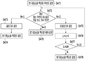
11 is a flowchart specifically showing the minutia truth determination step of Fig.
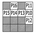
FIGS. 12 and 13 are views illustrating examples of determining whether a branch point is a minutia according to the method of FIG.
FIG. 14 is an exemplary view showing an example of evaluating whether the minutiae of FIG. 9 match. FIG.
이하, 첨부한 도면을 참고로 하여 본 발명의 여러 실시예들에 대하여 본 발명이 속하는 기술 분야에서 통상의 지식을 가진 자가 용이하게 실시할 수 있도록 상세히 설명한다. 본 발명은 여러 가지 상이한 형태로 구현될 수 있으며 여기에서 설명하는 실시예들에 한정되지 않는다.DETAILED DESCRIPTION OF THE PREFERRED EMBODIMENTS Hereinafter, embodiments of the present invention will be described in detail with reference to the accompanying drawings. The present invention may be embodied in many different forms and is not limited to the embodiments described herein.
본 발명을 명확하게 설명하기 위해서 설명과 관계없는 부분은 생략하였으며, 명세서 전체를 통하여 동일 또는 유사한 구성요소에 대해서는 동일한 참조 부호를 붙이도록 한다.In order to clearly illustrate the present invention, parts not related to the description are omitted, and the same or similar components are denoted by the same reference numerals throughout the specification.
또한, 명세서 전체에서, 어떤 부분이 어떤 구성요소를 "포함" 한다고 할 때, 이는 특별히 반대되는 기재가 없는 한 다른 구성요소를 제외하는 것이 아니라 다른 구성요소를 더 포함할 수 있는 것을 의미한다.Also, throughout the specification, when an element is referred to as "including" an element, it is understood that the element may include other elements as well, without departing from the other elements unless specifically stated otherwise.
하기에서 설명될 실시예들은 사용자의 지문을 인식(recognize)하는 데 사용될 수 있다. 이하, 사용자의 지문을 인식하는 동작은 사용자의 지문을 인식함으로써 그 사용자를 인증(verify)하거나 식별(identify)하는 동작을 포함할 수 있다. 사용자를 인증하는 동작은 그 사용자가 기 등록된 사용자인지 여부를 판단하는 동작을 포함할 수 있다. 이 경우, 사용자를 인증하는 동작의 결과는 참 또는 거짓으로 출력될 수 있다. 사용자를 식별하는 동작은 그 사용자가 기 등록된 복수의 사용자들 중 어느 사용자에 해당하는지를 판단하는 동작을 포함할 수 있다. 이 경우, 사용자를 식별하는 동작의 결과는 어느 하나의 미리 등록된 사용자의 아이디로서 출력될 수 있다. 만약 그 사용자가 미리 등록된 복수의 사용자들 중 어느 사용자에도 해당하지 않는 경우, 그 사용자가 식별되지 않음을 알리는 신호가 출력될 수도 있다.The embodiments described below can be used to recognize a fingerprint of a user. Hereinafter, the operation of recognizing the fingerprint of the user may include an operation of verifying or identifying the user by recognizing the fingerprint of the user. The operation of authenticating a user may include an operation of determining whether the user is an already registered user. In this case, the result of the operation of authenticating the user may be output as true or false. The operation of identifying a user may include an operation of determining which user of the plurality of registered users the user corresponds to. In this case, the result of the operation of identifying the user can be output as the ID of any one of the pre-registered users. If the user does not correspond to any of a plurality of users registered in advance, a signal indicating that the user is not identified may be output.
실시예들은 데스크톱 컴퓨터, 랩톱 컴퓨터, 태블릿 PC, 스마트 폰, 디지털 TV, 스마트 가전 기기, 지능형 자동차, 키오스크, 웨어러블 장치 등 다양한 형태의 제품으로 구현될 수 있다. Embodiments can be implemented in a variety of products such as desktop computers, laptop computers, tablet PCs, smart phones, digital TVs, smart home appliances, intelligent cars, kiosks, wearable devices,
예를 들어, 실시예들은 스마트 폰, 모바일 기기, 스마트 홈 시스템 등에서 사용자를 인증하는 데 사용될 수 있다. 실시예들은 사용자 인증을 통한 결제 서비스에서 사용될 수 있다. 또한, 실시예들은 사용자를 인증하여 자동으로 시동을 거는 지능형 자동차 시스템 등에도 적용될 수 있다. 이하, 실시예들을 첨부된 도면을 참조하여 상세하게 설명한다. For example, embodiments may be used to authenticate users in smart phones, mobile devices, smart home systems, and the like. Embodiments may be used in a payment service through user authentication. In addition, the embodiments can be applied to an intelligent automobile system that automatically authenticates a user and starts up. Hereinafter, embodiments will be described in detail with reference to the accompanying drawings.
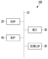
도 1은 실시예의 지문 인증 장치(100)를 개략적으로 나타낸 블록도(block diagram)이다. 도시된 바와 같이, 지문 인증 장치(100)는 센싱부(20), 메모리(30), 인터페이스부(50), 및 제어부(40)를 포함할 수 있다. 센싱부(20), 메모리(30), 인터페이스부(50), 및 제어부(40)는 버스(10)을 통해 서로 통신할 수 있다.1 is a block diagram schematically showing a
먼저, 센싱부(20)는 사용자의 손가락(경우에 따라서는 발가락)의 지문의 이미지를 획득(capture)할 수 있다. 센싱부(20)는 광학 방식, 열감지 방식, 및 정전용량 방식 등으로 지문 이미지를 획득할 수 있다.First, the
센싱부(20)는 사용자의 지문을 센싱하는 센싱 영역을 가질 수 있다. 이 때, 센싱부(20)의 센싱 영역의 크기는 지문의 크기보다 작을 수 있다. 이 경우, 센싱부(20)는 센싱 영역을 통하여 지문의 일부를 센싱할 수 있다.The
센싱부(20)는 센싱된 지문을 이용하여 지문 이미지를 생성할 수 있다. 지문 이미지는 사용자의 지문을 등록하거나 인식하는데 이용될 수 있다. 센싱부(20)의 센싱 영역의 크기가 지문의 크기보다 작은 경우, 센싱부(20)에 의해 생성되는 지문 이미지는 지문의 일부를 포함하는 부분 이미지(partial image)일 수 있다. 이하, 설명의 편의를 위하여 센싱부(20)가 획득한 이미지를 원본 이미지라고 지칭한다. 한편, 원본 이미지의 해상도는 300dpi 미만의 저해상도 이미지일 수 있다.The
다음으로, 메모리(30)는 지문 인증 장치(100)의 다양한 기능을 지원하는 데이터를 저장한다. 메모리(30)는 지문 인증 장치(100)의 동작을 위한 데이터들, 명령어들을 저장할 수 있다. Next, the memory 30 stores data supporting various functions of the
특히, 메모리(30)는 지문 이미지를 등록(enroll) 및 저장한다. 메모리(30)에는 센싱부(20)에서 획득한 원본 이미지 및 원본 이미지가 변형된 변형 이미지(modified image) 중 적어도 하나가 등록될 수 있다. 변형 이미지는 원본 이미지가 공간 영역에서 변형된 이미지, 주파수 영역에서 변형된 이미지 및 공간 영역과 주파수 영역에서 변형된 이미지 등을 나타낼 수 있다. 이하, 설명의 편의를 위하여 메모리(30)에 등록된 변형 이미지를 등록 변형 이미지라고 지칭한다.In particular, the memory 30 enrolls and stores the fingerprint image. At least one of the original image acquired by the
또한 메모리(30)는 지문 이미지들에 대응하는 특성 정보들을 저장할 수 있다. 예를 들어, 메모리(30)는 센싱부(20)에 의해 획득된 후 변형된 입력 변형 이미지, 제어부(40)에 의해 처리된 지문 이미지, 이미지 정합 결과, 이미지의 특징점 정보, 및 제어부(40)에 의해 계산된 스코어 등을 저장할 수 있다. 메모리(30)는 휘발성 메모리 또는 비휘발성 메모리일 수 있다.The memory 30 may also store characteristic information corresponding to the fingerprint images. For example, the memory 30 stores the deformed input deformed image obtained by the
제어부(40)는 지문 인식 장치의 적어도 하나의 다른 구성요소들을 제어하거나, 데이터 처리에 관련된 다양한 연산을 수행할 수 있다. 예를 들어, 제어부(40)는 CPU, AP(application processor), 또는 CP(communication processor) 중 하나 또는 그 이상을 포함할 수 있다.The
제어부(40)는 센싱부(20)로부터 획득된 지문 이미지를 일련의 절차에 따라 처리하여 변형 이미지를 생성하고, 생성한 변형 이미지를 메모리(30)에 등록 및 저장할 수 있다. The
또한, 제어부(40)는 센싱부(20)를 통해 획득된 지문 이미지에 기초하여 사용자의 지문 인증을 수행할 수 있다. 예를 들어, 제어부(40)는 메모리(30)에 저장된 등록 변형 이미지와 획득된 지문 이미지를 비교하여, 사용자(지문)의 인증을 수행할 수 있다. 제어부(40)에 의한 지문 인증 방법에 대하여는 도 2와 관련하여 후술한다.In addition, the
지문 인식 장치는 인터페이스부(50)를 통해 외부 기기에 연결되고, 데이터를 교환할 수 있다. 예를 들어, 인터페이스부(50)는 사용자 또는 다른 외부 기기로부터 입력된 명령 또는 데이터를 지문 인식 장치의 다른 구성요소에 전달할 수 있다. 또한, 인터페이스부(50)는 지문 인식 장치의 다른 구성요소로부터 수신된 명령 또는 데이터를 사용자 또는 다른 외부 기기로 출력할 수 있다.The fingerprint recognition device is connected to an external device through the interface part 50 and can exchange data. For example, the interface unit 50 may transmit commands or data input from a user or other external device to other components of the fingerprint recognition apparatus. In addition, the interface unit 50 can output the command or data received from the other components of the fingerprint recognition apparatus to the user or another external device.
상기 각 구성요소들 중 적어도 일부는, 이하에서 설명되는 다양한 실시 예들에 따른 지문 인식 장치의 동작, 제어, 또는 제어방법을 구현하기 위하여 서로 협력하여 동작할 수 있다. 또한, 상기 지문 인식 장치의 동작, 제어, 또는 제어방법은 상기 메모리(30)에 저장된 적어도 하나의 응용 프로그램의 구동에 의하여 지문 인식 장치 상에서 구현될 수 있다. At least some of the components may operate in cooperation with each other to implement a method of operation, control, or control of a fingerprint recognition device in accordance with various embodiments described below. In addition, the operation, control, or control method of the fingerprint recognition device may be implemented on the fingerprint recognition device by driving at least one application program stored in the memory 30.
이하에서는 실시예의 지문 인식 장치에 의해 수행될 수 있는 지문 인식 방법에 대해 도 2 내지 도 14를 참조하여 설명한다.Hereinafter, a fingerprint recognition method that can be performed by the fingerprint recognition apparatus of the embodiment will be described with reference to FIG. 2 to FIG.
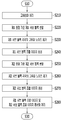
도 2는 실시예의 지문 인증 방법을 개략적으로 나타낸 순서도(flow chart)이다.2 is a flow chart schematically showing the fingerprint authentication method of the embodiment.
먼저, 센싱부(20)는 지문 이미지를 획득(S10)한다. 센싱부(20)는 센싱 영역을 통해 사용자의 지문을 센싱하여, 지문 이미지(원본 이미지)를 획득할 수 있다. First, the
그러면, 제어부(40)는 원본 이미지를 이미지 처리(S20)한다. 제어부(40)는 원본 이미지를 고해상도 이미지로 변환(이하에서는 고해상화 처리)하고, 변환된 이미지의 노이즈를 제거하고, 노이즈가 제거된 이미지들을 평균화하여 하나의 입력 변형 이미지로 가공하는 이미지 처리를 수행할 수 있다. 제어부(40)는 원본 이미지를, LBP(local binary pattern) 타입, HOG(histogram of oriented gradients) 타입, Haar feature 타입, MCT(Modified Census Transform) 타입, N비트로 양자화된(N-bit quantized) 타입(여기서, N은 1이상의 정수), 및 기하학적으로 변형(warping)된 타입으로 변형된 이미지 등으로 변형, 가공할 수도 있다. 여기서, 제어부(40)가 원본 이미지를 이미지 처리하는 방식은 이에 제한되지 않는다.Then, the
다음으로, 제어부(40)는 입력 변형 이미지와 등록 변형 이미지를 정합(S30)하고, 입력 변형 이미지와 등록 변형 이미지의 특징점을 평가(S40)한다.Next, the
그러면, 제어부(40)는 이미지 정합의 결과 및 특징점 평가 결과를 이용하여, 입력 변형 이미지와 등록 변형 이미지가 일치하는지 여부를 판정(S50)한다. 입력 변형 이미지와 등록 변형 이미지가 일치하는지 여부에 따라, 사용자 인증(verification) 결과 또는 사용자 식별(identification) 결과가 도출될 수 있다.Then, the
이하에서는, 도 3 내지 도 6을 참조하여 도 2의 이미지 처리 단계(S20)를 구체적으로 설명한다. Hereinafter, the image processing step S20 of FIG. 2 will be described in detail with reference to FIG. 3 to FIG.
도 3은 도 2의 지문 이미지 처리 단계를 구체적으로 나타낸 순서도이다. FIG. 3 is a flowchart illustrating the fingerprint image processing step of FIG. 2 in detail.
제어부(40)는 센싱부(20)에서 획득된 원본 이미지를 고해상화 처리(S210)한다. 고해상화 처리와 관련하여 도 4를 함께 참조한다.The
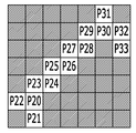
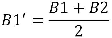
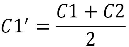
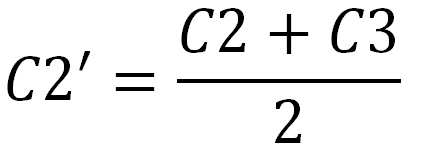
도 4는 도 3의 고해상화 처리의 일 예를 나타낸 예시도이다. 원본 이미지는 M×N개의 화소로 구성된 이미지 데이터일 수 있다. 도 4의 (a)는 저해상도의 원본 이미지의 일부를 모식적으로 나타낸 도면이다. 원본 이미지의 일부는 3×3개의 화소 배열을 포함하고, 화소 각각은 휘도 값(A1-A3, B1-B3, C1-C3)을 포함할 수 있다.4 is an exemplary view showing an example of the high-definition processing in Fig. The original image may be image data composed of M x N pixels. 4A is a diagram schematically showing a part of an original image of low resolution. A part of the original image includes 3 × 3 pixel arrays, and each of the pixels may include a luminance value (A1-A3, B1-B3, C1-C3).
제어부(40)는 (2×M)×(2×N)개의 화소 배열을 마련한다. 그리고, 제어부(40)는 원본 이미지의 위치(i, j)에 있는 화소의 휘도 값을 (2×M)×(2×N)개의 화소 배열 내의 위치(2×i, 2×j)에 있는 화소, 위치(2×i+1, 2×j)에 있는 화소, 위치(2×i, 2×j+1)에 있는 화소, 위치 (2×i+1, 2×j+1)에 있는 화소에 복사한다. 여기서, i 및 j는 1 이상의 정수이다. 그러면 제어부(40)는 3×3 화소 배열을, 도 4의 (b)에 도시된 바와 같이 6×6 화소 배열로 변환할 수 있다.The
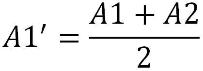
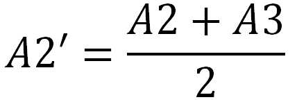
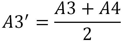
그 다음, 제어부(40)는 도 4의 (b)의 화소 배열을 하나의 화소만큼 오른쪽으로 이동시킨 화소 배열에 도 4의 (b)의 화소 배열을 더하여 각 화소 마다 평균 휘도 값을 계산한다. 그러면 제어부(40)는 도 4의 (c)에 도시된 바와 같은 6×6 화소 배열을 구성할 수 있다. 여기서, A1'-A3', B1'-B3', C1'-C3'은 다음의 수학식 1 내지 9로 나타낼 수 있다.Then, the


그 다음, 제어부(40)는 도 4의 (c)의 화소 배열을 하나의 화소만큼 위쪽으로 이동시킨 화소 배열에 도 4의 (c)의 화소 배열을 더하여 각 화소 마다 평균 휘도 값을 계산한다. 그러면 제어부(40)는 도 4의 (d)에 도시된 바와 같은 6×6 화소 배열을 구성할 수 있다. Next, the
다음으로, 제어부(40)는 고해상화 처리 이미지의 제1 원점을 기준으로 고해상화 처리 이미지를 서브 블록 단위로 분할(S220)한다. 제1 원점을 기준으로 분할된 서브 블록들을 제1 서브 블록들로 설명한다.Next, the
제어부(40)는 제1 서브 블록들 각각의 고주파 노이즈를 제거(S230)한다. 제어부(40)는 서브 블록들 각각을 주파수 도메인으로 변환할 수 있다. 여기서, 주파수 도메인 변환 방식은 빠른 푸리에 변환(FFT: Fast Fourier Transform), 이산 푸리에 변환(DFT: Discrete Fourier Transform) 등의 2차원 푸리에 변환을 포함한다. The
제어부(40)는 각각의 제1 서브 블록에 대해, 2차원 푸리에 변환된 실수부(Re)와 허수부(Im)를 산출하여, 각각의 제1 서브 블록의 공간 주파수 특성을 획득할 수 있다. The
일반적으로, 지문 이미지 내의 지문의 융선(Ridge)은 노이즈에 비해 공간 주파수가 더 낮다. 제어부(40)는 노이즈를 제거하기 위해, 실수부(Re)와 허수부(Im)를 저주파 통과 필터(LPF: Low Pass Filter)에 통과시켜 고주파 성분을 제거할 수 있다. Generally, a ridge of a fingerprint in a fingerprint image has a lower spatial frequency than noise. The
제어부(40)는 저주파 성분에 대해, 주파수 피크(peak)를 강조하기 위해, 실수부(Re)와 허수부(Im) 각각에 계수를 승산할 수 있다. 또는 제어부(40)는 저주파 성분에 대해, 주파수 피크(peak)를 강조하기 위해, 실수부(Re)와 허수부(Im) 각각에 Re^2+Im^2의 제곱근을 승산할 수 있다. 제어부(40)는 강조 처리된 실수부(Re')와 허수부(Im')를 역 푸리에 변환할 수 있다. 그러면, 제어부(40)는 각각의 제1 서브 블록 마다 융선이 강조된 이미지를 획득할 수 있다.The
제어부(40)는 각각의 제1 서브 블록의 융선이 강조된 이미지를 연결하여, 제1 서브 블록 이미지를 생성(S240)한다. The
제어부(40)는 고해상화 처리 이미지의 제2 원점을 기준으로 고해상화 처리 이미지를 서브 블록 단위로 분할(S250)한다. 제2 원점을 기준으로 분할된 서브 블록들을 제2 서브 블록들로 설명한다.The
제어부(40)의 제1 원점 기준 서브 블록 분할 단계(S220) 및 제2 원점 기준 서브 블록 분할 단계(S250)에 대해 도 5를 함께 참조하여 설명한다.The first origin-based subblock division step S220 and the second origin-based subblock division step S250 of the
도 5는 도 3의 서브 블록 분할의 일 예를 나타낸 예시도이다. 먼저, 도 5의 (a)에 도시된 바와 같이, 이미지(PIM)의 제1 영역(A1)에 제1 원점 및 제2 원점이 설정되는 예를 들어 설명한다.5 is an exemplary view showing an example of sub-block division in FIG. First, as shown in FIG. 5A, an example in which a first origin and a second origin are set in the first area A1 of the image PIM will be described.
도 5의 (b)에 도시된 바와 같이, 제어부(40)는 (0,0)의 화소(PX)를 제1 원점으로 설정할 수 있다. 제어부(40)는 제1 원점을 기준으로 dx×dy개(dx, dy는 자연수)의 화소를 서브 블록 단위로 설정할 수 있다. 그러나, 발명이 이에 한정되는 것은 아니고, 제어부(40)는 서브 블록 단위를 임의의 화소 개수로 설정할 수 있다. 또한, 서브 블록 단위의 형태는 삼각형, 사각형, 육각형과 같은 다각형, 원형, 타원형 등일 수 있으나, 이에 제한되지 않는 임의의 형태를 가질 수 있다. As shown in FIG. 5B, the
제어부(40)는 제1 원점(0,0)을 기준으로, x축 방향을 따라 dx개의 화소(dx-1,0)까지를 제1 변, y축 방향을 따라 dy개의 화소(0,dy-1)까지를 제2 변으로 하는 사각 형태의 영역을 하나의 서브 블록으로 설정할 수 있다. 즉, 제1 서브 블록(BA11)은 (0,0)의 화소, (dx-1,0)의 화소, (0,dy-1)의 화소, (dx-1,dy-1)의 화소를 각각 꼭짓점으로 포함하는 사각 형태의 영역 내에 위치한 화소를 포함할 수 있다. The
이와 마찬가지로, 제1 서브 블록(BA11)과 x축 방향으로 인접한 제1 서브 블록(BA12)은 (dx,0)의 화소, (2dx-1,0)의 화소, (dx,dy-1)의 화소, (2dx-1,dy-1)의 화소를 각각 꼭짓점으로 포함하는 사각 형태의 영역 내에 위치한 화소를 포함할 수 있다. 그리고 제1 서브 블록(BA11)과 y축 방향으로 인접한 제1 서브 블록(BA21)은 (0,dy)의 화소, (dx-1,dy)의 화소, (0,2dy-1)의 화소, (dx-1,2dy-1)의 화소를 각각 꼭짓점으로 포함하는 사각 형태의 영역 내에 위치한 화소를 포함할 수 있다.Similarly, the first sub-block BA12 adjacent to the first sub-block BA11 in the x-axis direction is divided into (dx, 0) And pixels located within a rectangular area including pixels of (2dx-1, dy-1) as vertexes, respectively. The first sub-block BA21 adjacent to the first sub-block BA11 in the y-axis direction is a pixel of (0, dy), a pixel of (dx-1, dy) (dx-1, 2dy-1) as pixels, respectively.
즉, 제어부(40)는 단계(S220)에서 제1 원점(0,0)을 기준으로, 제1 서브 블록들(BA11~BA13, BA21~BA23, BA31~BA33)로 이미지(PIM)를 분할할 수 있다. 그리고, 제어부(40)는 단계(S230) 및 단계(S240)를 수행하여 제1 서브 블록 조합 이미지를 생성할 수 있다.That is, the
다음으로, 도 5의 (c)에 도시된 바와 같이, 제어부(40)는 (ax,ay)의 화소(PX)를 제2 원점으로 설정할 수 있다. 이때, 제어부(40)는 제2 원점을 기준으로 dx×dy개의 화소를 서브 블록 단위로 설정할 수 있다. 제어부(40)는 단계(S220)와 단계(S250)에서 설정되는 서브 블록 단위의 형태, 서브 블록 단위에 포함되는 화소의 개수를 서로 다르게 설정할 수 있다.Next, as shown in Fig. 5C, the
제어부(40)는 제2 원점(ax,ay)을 기준으로, x축 방향을 따라 dx개의 화소(dx+ax-1,ay)까지를 제1 변, y축 방향을 따라 dy개의 화소(ax,dy+ay-1)까지를 제2 변으로 하는 사각 형태의 영역을 하나의 서브 블록으로 설정할 수 있다. 즉, 제2 서브 블록(BB11)은 (ax,ay)의 화소, (dx+ax-1,ay)의 화소, (ax,dy+ay-1)의 화소, (dx+ax-1,dy+ay-1)의 화소를 각각 꼭짓점으로 포함하는 사각 형태의 영역 내에 위치한 화소를 포함할 수 있다. The
이와 마찬가지로, 제2 서브 블록(BB11)과 x축 방향으로 인접한 제2 서브 블록(BB12)은 (dx+ax,ay)의 화소, (2dx+ax-1,ay)의 화소, (dx+ax,dy+ay-1)의 화소, (2dx+ax-1,dy+ay-1)의 화소를 각각 꼭짓점으로 포함하는 사각 형태의 영역 내에 위치한 화소를 포함할 수 있다. 그리고 제2 서브 블록(BB11)과 y축 방향으로 인접한 제2 서브 블록(BB21)은 (ax,dy+ay)의 화소, (dx+ax-1,dy+ay)의 화소, (ax,2dy+ay-1)의 화소, (dx+ax-1,2dy+ay-1)의 화소를 각각 꼭짓점으로 포함하는 사각 형태의 영역 내에 위치한 화소를 포함할 수 있다.Likewise, the second sub-block BB11 and the second sub-block BB12 adjacent in the x-axis direction are pixels of (dx + ax, ay), pixels of (2dx + ax- , dy + ay-1, and pixels of (2dx + ax-1, dy + ay-1) as vertexes. The second sub-block BB11 adjacent to the second sub-block BB11 in the y-axis direction is a pixel of (ax, dy + ay), a pixel of (dx + ax-1, dy + ay) + ay-1), and (dx + ax-1,2dy + ay-1), respectively.
즉, 제어부(40)는 단계(S250)에서 제2 원점(ax,ay)을 기준으로, 제2 서브 블록들(BB11~BB13, BB21~BB23, BB31~BB33)로 이미지(PIM)를 분할할 수 있다. 그리고, 제어부(40)는 단계(S230) 및 단계(S240)와 유사하게, 단계(S260) 및 단계(S270)를 수행하여 제2 서브 블록 조합 이미지를 생성할 수 있다.That is, in step S250, the
이외에도 제어부(40)는 필요에 의해, 임의의 화소를 제3 원점으로 설정하여 이미지(PIM)을 서브 블록들로 분할하고, 고주파 노이즈를 제거하여 제3 서브 블록 조합 이미지를 생성할 수 있다. In addition, the
제어부(40)는 제1 원점 및 제2 원점 각각을 기준으로 한, 제1 및 제2 서브 블록 조합 이미지를 평균화 처리(S280)한다. 단계(S280)의 평균화 처리에 대해서 도 6을 함께 참조하여 설명한다.The
도 6은 도 3의 평균화 처리와 관련된 지문 이미지의 일 예를 나타낸 예시도이다. 먼저 도 6의 (a)는 단계(S210)에서 고해상화 처리된 이미지를 나타낸다.FIG. 6 is an exemplary view showing an example of a fingerprint image related to the averaging process of FIG. 3; First, FIG. 6A shows an image obtained in step S210.
그리고, 도 6의 (b), (c), 및 (d)는 단계(S220) 내지 단계(S270)에 따라 생성된 서브 블록 조합 이미지를 나타낸다. 강조 처리된 이미지는 서브 블록의 경계에서 융선이 서로 어긋날 수 있다. 즉, 강조 처리된 이미지 내의 적어도 하나의 서브 블록의 경계에서 융선이 불연속할 수 있다.6 (b), 6 (c), and 6 (d) show sub-block combination images generated according to steps S220 to S270. The highlighted image may have ridges at the boundaries of the sub-blocks. That is, ridges may be discontinuous at the boundary of at least one sub-block in the emphasized image.
제어부(40)는 도 6의 (e)에 도시된 바와 같이, 강조 처리된 이미지들을 평균화(image blending) 처리할 수 있다. 평균화는 산술 평균화, 웨이트(weight) 계수를 고려한 평균화 처리(예를 들어, 알파 블렌딩)일 수 있다. 또한 평균화 처리하는 조합 이미지의 개수는 제한이 없고, 조합 이미지가 많을수록 매끄러운 이미지가 생성될 수 있다.The
이하에서는, 도 7 및 도 8을 참조하여 도 2의 이미지 정합 단계(S30)를 구체적으로 설명한다.Hereinafter, the image matching step (S30) of Fig. 2 will be described in detail with reference to Figs. 7 and 8. Fig.
도 7은 도 2의 이미지 정합 단계를 구체적으로 나타낸 순서도이다. 제어부(40)는 등록 변형 이미지와 획득된 지문 이미지로부터 평균화 처리된 이미지를 이미지 정합할 수 있다. FIG. 7 is a flowchart showing the image matching step of FIG. 2 in detail. The
일 실시예에 따르면 이미지 정합은 서로 다른 이미지를 변형하여 하나의 좌표계에 나타내는 처리 방식이다. 이미지 정합을 통해, 상이한 이미지들이 서로 어떻게 대응되는지 파악될 수 있다. According to one embodiment, image matching is a processing method in which different images are transformed and displayed in one coordinate system. Through image registration, it can be understood how different images correspond to each other.
제어부(40)는 도 7에 도시된 바와 같이, 메모리(30)로부터 등록 변형 이미지를 판독(S310)한다.The
다음으로, 제어부(40)는 평균화 처리된 이미지의 일 부분을 기준 이미지로 결정(S320)한다. 이때, 기준 이미지로 결정된 이미지의 일 부분이 전체 이미지의 소정 비율의 면적을 가지도록, 제어부(40)는 기준 이미지를 결정할 수 있다. 예를 들어, 제어부(40)는 기준 이미지가 전체 이미지의 5% 내지 10%의 면적을 가지도록 기준 이미지를 결정할 수 있다. Next, the
그리고, 제어부(40)는 위상 한정 상관법(POC: Phase only Correlation)을 이용하여, 등록 변형 이미지 및 기준 이미지 간의 중첩 영역을 판정(S330)한다. Then, the
푸리에 공간에서 두 이미지의 위상 간 상호 상관 값을 계산하여 신규 이미지(예를 들어, 상관 강도 이미지)를 생성하면, 신규 이미지에서 최댓값이 나타나는 부분(예를 들어, 상관 강도가 높은 피크)이 두 이미지 간의 상대적인 위치 관계가 될 수 있다. 일례로, 제어부(40)는 상관 강도의 가장 높은 상관 값 및 그 상관 값의 피크 위치를, 등록 변형 이미지와 기준 이미지의 2차원 상의 위치 관계로서 특정한다. When a new image (e.g., a correlation intensity image) is generated by calculating the cross-correlation value between the phases of two images in the Fourier space, a portion where the maximum value appears in the new image (e.g., As shown in FIG. In one example, the
제어부(40)는 복수의 상관 값 및 그것에 대응하는 피크 위치에 기초하여, 기준 이미지의 위치를 보정(S340)한다. 예를 들어, 제어부(40)는 기준 이미지의 패턴과 등록 변형 이미지의 패턴이 서로 일치하도록, 기준 이미지를 평행 이동할 수 있다.The
제어부(40)는 두 이미지 사이의 유사한 정도를 나타내는 상관 계수를 계산(S350)한다. 예를 들어, 제어부(40)는 제로-민 노말라이즈드 크로스 코릴레이션(ZNCC: Zero-mean normalized cross correlation)을 사용하여 등록 변형 이미지에 대해 기준 이미지가 얼마나 유사한지를 0 내지 1의 값을 갖는 상관 계수로서 나타낼 수 있다. The
제어부(40)는 두 이미지, 즉 기준 이미지와 중첩하는 것으로 판정된 등록 변형 이미지의 일 영역 및 기준 이미지에 각각 포함된 화소들의 밝기, 에지(edge) 성분, 색좌표 등을 비교한 후, 이를 정규화(normalized)하여 상관 정도를 0부터 1까지의 값 중 하나로 나타낼 수 있다. 제어부(40)는 상관 정도가 0에 가까우면 두 이미지의 유사도가 낮은 것이고, 상관 정도가 1에 가까우면 두 이미지가 동일한 것으로 결정할 수 있다. ZNCC를 사용하여 이미지의 유사도를 나타내는 방법은 영상 처리 분야에서 당업자에게 공지되어 있으므로 자세한 설명은 생략한다.The
그러면, 제어부(40)는 상관 계수가 임계치를 초과하는지 판단(S360)한다.Then, the
제어부(40)는 상관 계수가 임계치를 초과하지 않는 경우, 기준 이미지를 회전 보정(S370)한다. 이때, 기준 이미지가 회전 보정되는 각도는 임의의 각도 값으로 설정될 수 있다. 예를 들어, 단계(S360)에서, 제어부(40)는 기준 이미지를 시계 방향을 따라 5도 단위, 10도 단위, 또는 15도 단위 등으로 회전 보정할 수 있다. If the correlation coefficient does not exceed the threshold value, the
제어부(40)는 단계(S330) 내지 단계(S370)의 루프 내에서는 하나의 각도 값만을 이용하여, 기준 이미지를 회전 보정할 수 있다. 예를 들어, 제어부(40)는 단계(S370)에서, 기준 이미지를 10도 단위로만 회전시켜 보정할 수 있다.The
그 다음 제어부(40)는 다시 POC를 사용하여 중첩 영역을 판정(S330)한다.Then, the
즉, 제어부(40)는 계산된 상관 계수의 값에 따라, 기준 이미지의 회전 각도를 점진적으로 증가(또는 감소)시켜 보정한다. 즉, 단계(S330) 내지 단계(S370)가 반복적으로 수행되어, 기준 이미지와 등록 변형 이미지 간의 위치 관계 및 회전 각도가 보정된다. That is, the
한편, 제어부(40)는 상관 계수가 임계치를 초과하는 경우, 계산된 상관 계수, 회전 각도 보정 값, 및 위치 보정 값(예를 들어, 평행 이동 값)을 저장(S380)한다. 제어부(40)는 상관 계수, 회전 각도 보정 값, 및 위치 보정 값을 평균화 처리된 이미지에 관련시켜 저장할 수 있다. 즉, 제어부(40)는 두 이미지 간의 최대 상관 계수를 갖는 위치 관계 및 회전 각도를 저장할 수 있다.Meanwhile, when the correlation coefficient exceeds the threshold value, the
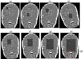
도 8은 도 7에서 전체 이미지에 대한 기준 이미지의 비율 변화에 따른 이미지 정합을 나타낸 예시도이다.8 is an exemplary view showing an image registration according to a change in a ratio of a reference image to an entire image in FIG.
도 8의 (a) 내지 도 8의 (d)는 전체 이미지에 대해 각각 1%, 2%, 3%, 4%의 면적으로 기준 이미지들을 결정하여 등록 변형 이미지에 대해 이미지 정합을 수행한 결과를 나타낸다.FIGS. 8A to 8D show the result of performing image matching on a registered deformation image by determining reference images with an area of 1%, 2%, 3%, and 4%, respectively, .
도 8의 (a) 내지 도 8의 (d)에서, 등록 변형 이미지에 대한 기준 이미지의 위치, 기준 이미지와 등록 변형 이미지가 이루는 각도가 상이하다.8A to 8D, the position of the reference image with respect to the registered deformation image, and the angle formed between the reference image and the registered deformation image are different.
도 8의 (e) 내지 도 8의 (h)는 전체 이미지에 대해 각각 5%, 10%, 20%, 30%의 면적으로 기준 이미지들을 결정하여 등록 변형 이미지에 대해 이미지 정합을 수행한 결과를 나타낸다.8 (e) to 8 (h) show reference images determined by 5%, 10%, 20%, and 30% areas of the entire image, respectively, .
도 8의 (e) 내지 도 8의 (h)에서, 등록 변형 이미지에 대한 기준 이미지의 위치, 기준 이미지와 등록 변형 이미지가 이루는 각도가 각 도면 마다 서로 동일하다. 그러므로, 이미지 정합성을 높일 수 있도록, 기준 이미지는 평균화 처리된 이미지 전체에 대해 5% 이상의 면적 비율을 갖는 영역을 포함할 수 있다.8 (e) to 8 (h), the position of the reference image with respect to the registered deformation image, and the angle between the reference image and the registered deformation image are the same for each drawing. Therefore, in order to enhance the image matching, the reference image may include an area having an area ratio of 5% or more with respect to the entire averaged image.
한편, 기준 이미지가 전체 이미지에 대해 40%를 초과하는 경우, 기준 이미지는 전체 이미지의 코어(core) 영역(CA)을 포함하여 결정될 수 있다. 코어 영역은 융선 패턴의 명확하지 않을 수 있다. 그러므로, 코어 영역을 제외한 영역을 기준 영역으로 갖도록, 기준 이미지는 평균화 처리된 이미지 전체에 대해 40% 이내의 면적 비율을 갖는 영역을 포함할 수 있다. On the other hand, when the reference image exceeds 40% with respect to the entire image, the reference image may be determined including the core region CA of the entire image. The core region may not be clear of the ridge pattern. Therefore, the reference image may include an area having an area ratio within 40% with respect to the entire averaged image so as to have the area excluding the core area as the reference area.
다음으로, 도 9 내지 도 12를 참조하여 도 2의 특징점 평가 단계(S40)를 구체적으로 설명한다.Next, the minutiae evaluation step (S40) of Fig. 2 will be described in detail with reference to Figs. 9 to 12. Fig.
도 9는 도 2의 특징점 평가 단계를 구체적으로 나타낸 순서도이다. 도 9에 도시된 바와 같이, 제어부(40)는 회전 각도 보정 값 및 위치 보정 값을 이용하여, 평균화 처리된 이미지를 보정(S410)한다. 제어부(40)는 회전 각도 보정 값을 이용하여 평균화 처리된 이미지를 회전 처리하고, 위치 보정 값을 이용하여 회전 처리된 이미지를 평행 이동 처리할 수 있다. 또는 제어부(40)는 위치 보정 값을 이용하여 평균화 처리된 이미지를 평행 이동 처리한 후, 회전 각도 보정 값을 이용하여 평행 이동 처리된 이미지를 회전 처리할 수 있다.FIG. 9 is a flowchart specifically showing the minutiae evaluation step of FIG. 2. FIG. As shown in FIG. 9, the
제어부(40)는 보정된 이미지를 서브 블록 단위로 분할(S420)한다. 제어부(40)는 m×n개(m, n은 자연수)의 화소 단위를 서브 블록 단위로 설정할 수 있다. 도 9의 서브 블록 단위 도 5에서 설명한 서브 블록 단위와 동일하거나 상이할 수 있다.The
제어부(40)는 각각의 서브 블록 내의 화소 휘도 편차를 계산(S430)한다. 구체적으로, 제어부(40)는 서브 블록 내에 위치한 화소들의 휘도 평균을 계산할 수 있다. 제어부(40)는 휘도 평균과 서브 블록 내의 각 화소의 휘도 사이의 차이를 계산하고, 각각의 차이들의 절대 값의 평균을 휘도 편차 값으로서 계산한다.The
그러면, 제어부(40)는 휘도 편차 값이 포함되는 범위에 따라 가중치 계수를 서브 블록 별로 결정(S440)한다. 예를 들어, 제어부(40)는 휘도 편차 값이, (1) 0 이상 a(a>0) 미만인 경우, 해당 서브 블록에 대응하는 가중치 계수를 0.5로 결정하고, (2) a 이상 b(b>a>0) 미만인 경우, 해당 서브 블록에 대응하는 가중치 계수를 1로 결정하며, (3) b 이상인 경우, 해당 서브 블록에 대응하는 가중치 계수를 2로 결정한다.Then, the
단계(S420) 내지 단계(S440)와 관련하여 도 10을 함께 참조하여 설명한다.Referring to Fig. 10 together with steps S420 to S440, description will be made.
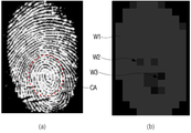
도 10은 도 9의 서브 블록 분할 후에 계산된 휘도 편차의 일 예를 나타낸 예시도이다. 10 is an exemplary view showing an example of a luminance deviation calculated after sub-block division in FIG.
도 10의 (a)는 원본 이미지를 나타내고, 도 10의 (b)는 원본 이미지에 대응하는 가중치 계수를 서브 블록 별로 모식적으로 나타낸다. 도 10의 (b)에서 각 서브 블록은 세 개의 가중치 계수(W1, W2, W3) 중 적어도 하나를 가진다. 10 (a) shows an original image, and FIG. 10 (b) schematically shows a weight coefficient corresponding to an original image on a sub-block basis. In FIG. 10B, each sub-block has at least one of three weighting coefficients W1, W2 and W3.
도 10의 (a)와 도 10의 (b)를 비교하면, 도 10의 (a)의 코어 영역(CA)에 대응하는 영역에는 휘도 편차 값이 작은 서브 블록이 분포한다. 코어 영역(CA)의 경우, 융선의 패턴이 명확하게 인식되지 않을 수 있어, 평균적으로 높은 휘도를 갖는 화소가 위치할 수 있다. 그러므로, 코어 영역(CA)에 대응하는 서브 블록은 비교적 작은 값을 갖는 가중치 계수(W3) 또는 가중치 계수(W2)로 결정되는 경향이 있다. 10 (a) and 10 (b), sub-blocks having a small luminance deviation value are distributed in a region corresponding to the core region CA in FIG. 10 (a). In the case of the core region CA, a pattern of ridges may not be clearly recognized, and a pixel having an average high luminance may be located. Therefore, the sub-block corresponding to the core region CA tends to be determined by the weight coefficient W3 or the weight coefficient W2 having a relatively small value.
코어 영역(CA) 외의 영역은 비교적 융선이 명확하게 인식되어, 코어 영역(CA) 외의 영역에 위치하는 서브 블록 내의 화소들 간의 휘도 편차가 크게 나타나는 경향이 있다. 그러므로, 코어 영역(CA) 외의 영역에 위치하는 서브 블록은 비교적 높은 값을 갖는 가중치 계수(W1)로 결정된다. 즉, 융선이 비교적 명확하게 인식된 영역(즉, 신뢰도가 높은 영역)에 위치하는 특징점에 대해 평가할 때, 더 높은 가중치 계수를 부여할 수 있다.The ridges in the regions other than the core region CA are clearly recognized as ridges and the luminance deviations between the pixels in the sub-blocks located in the regions other than the core region CA tend to appear. Therefore, a sub-block located in an area other than the core area CA is determined by a weight coefficient W1 having a relatively high value. That is, when evaluating a feature point located in a region in which a ridge is relatively clearly recognized (i.e., a region with high reliability), a higher weight coefficient can be given.
상이한 값으로 결정된 가중치 계수에 따라, 이후의 특징점 평가 단계에서 각각의 특징점이 위치한 서브 블록의 가중치 계수를 고려하여 특징점 일치 여부를 평가할 수 있다.It is possible to evaluate the coincidence between the feature points by considering the weight coefficients of the sub-blocks in which the respective feature points are located, in the subsequent feature point evaluation step, according to the weight coefficients determined as different values.
이어서, 도 9를 다시 참조하면, 제어부(40)는 이미지에 대해 이진화(binarization)를 수행(S450)한다. 이진화는 임계치 보다 휘도가 높은 화소들은 모두 최대 휘도 값(예를 들어, 1 비트의 이진화 이미지로 나타내면, 1)으로 변경하고, 임계치 보다 휘도가 같거나 낮은 화소들은 모두 최소 휘도 값(예를 들어, 1 비트의 이진화 이미지로 나타내면, 0)으로 바꾸는 것을 지칭한다. 이미지 이진화 방법은 영상 처리 분야에서 당업자에게 공지되어 있으므로 자세한 설명은 생략한다.Referring again to FIG. 9, the
제어부(40)는 이진화된 이미지로부터 특징점을 검출(S460)한다. 이진화된 이미지에서 지문의 특징점, 즉, 융선의 끝점(ridge end)이나 분기점(bifurcation) 등의 세밀한 특징점인 미뉴샤(minutiae)가 존재할 수 있다. The
제어부(40)는 검출된 특징점들 중 분기점의 진위를 판정(S470)한다. 원본 이미지의 해상도가 낮은 경우, 인접한 융선들이 서로 완전하게 분리되지 않고, 노이즈 등에 의해 서로 연결될 수 있다. 이 경우, 노이즈에 의해 연결된 지점(이하, 가짜 분기점)이 분기점으로 검출될 수 있으므로, 제어부(40)는 각각의 분기점들 마다 진위를 판정할 수 있다. The
가짜 분기점은 노이즈에 의해 형성되므로, 가짜 분기점들 사이의 거리가 진짜 분기점들 사이의 거리에 비해 가깝다. 이러한 특징을 고려하여 이하에서 특징점 진위를 판정하는 방법을 도 11 및 도 12를 함께 참조하여 설명한다. Since the false branch point is formed by noise, the distance between the false branch points is closer to the distance between the real branch points. A method for determining the feature point authenticity will be described below with reference to Figs. 11 and 12 in consideration of these features. Fig.
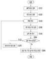
도 11은 도 9의 특징점 진위 판정 단계를 구체적으로 나타낸 순서도이고, 도 12 및 도 13은 도 11의 방식에 따라 분기점이 특징점인지 판단하는 예들을 나타낸 예시도이다.FIG. 11 is a flow chart specifically showing the minutia truth determination step of FIG. 9, and FIGS. 12 and 13 are examples of judging whether a minutia point is a minutia point according to the method of FIG.
먼저, 한 화소는 네 방향(상, 하, 좌, 우)으로 인접한 화소들과 연결될 수 있다. 분기점은 세 방향으로 인접한 화소들과 연결된 지점이고, 끝점은 한 방향으로 인접한 화소와 연결된 지점이며, 연결점은 두 방향으로 인접한 화소들과 연결된 지점이다.First, one pixel can be connected to adjacent pixels in four directions (up, down, left, right). A branch point is a point connected to adjacent pixels in three directions, an end point is a point connected to adjacent pixels in one direction, and a connection point is a point connected to adjacent pixels in two directions.
도 11에 도시된 바와 같이, 제어부(40)는 분기점들 중 어느 하나의 분기점(a)을 특징점 후보로서 결정(S471)한다. 도 12 및 도 13에 도시된 바와 같이, 이진화된 이미지 내에서 분기점(도 12의 P10, 도 13의 P20)을 특징점 후보로서 결정한다.As shown in Fig. 11, the
그러면, 제어부(40)는 대상 화소(분기점(a))의 주변 화소들의 연결 화소 개수를 판단(S472)한다. 즉, 제어부(40)는 분기점(a)을 기준으로, 분기점(a)의 주변에 위치하는 화소가 끝점, 연결점, 또는 분기점인지를 판단한다.Then, the
주변에 위치하는 화소가 끝점, 연결점, 또는 분기점인지 확인하기 위해, 제어부(40)는 주변에 위치하는 화소가 몇 개의 방향으로 인접한 화소들과 연결되어 있는지 판단한다.In order to confirm whether the surrounding pixel is an end point, a connection point, or a branch point, the
도 12에서 제어부(40)는 화소(P10)의 주변에 위치하는 화소가 몇 개의 방향으로 인접한 화소들과 연결되어 있는지 판단한다. 예를 들어, 제어부(40)는 화소(P10) 좌측의 화소(P13), 상측의 화소(P11), 및 하측의 화소(P12)가 몇 개의 방향으로 인접한 화소들과 연결되어 있는지 판단할 수 있다. In FIG. 12, the
또한, 도 13를 참조하면, 제어부(40)는 화소(P20)의 상측의 화소(P23), 좌측의 화소(P22), 하측의 화소(P21)가 몇 개의 방향으로 인접한 화소들과 연결되어 있는지 판단할 수 있다.13, the
제어부(40)는 대상 화소의 주변의 화소가 하나의 방향으로 인접한 화소와 연결되어 있으면, 그 주변 화소를 끝점으로서 결정(S473)한다. 예를 들어, 도 12에서 화소(P10)의 하측의 화소(P12)가 연결된 화소는 화소(P10)이다. 화소(P10)의 하측의 화소(P12)는 하나의 방향으로 인접한 화소(P10)와 연결되어 있으므로, 끝점으로서 결정된다.If the peripheral pixel of the target pixel is connected to the adjacent pixel in one direction, the
한편, 대상 화소(분기점(a))의 주변에 끝점만 존재하는 경우, 즉 분기점(a)에 대해 단계(S472)만 수행되고, 단계(S475) 및 단계(S479)가 수행되지 않는 경우, 제어부(40)는 대상 화소(분기점(a)) 주변에 다른 분기점이 존재하지 않으므로, 해당 대상 화소(분기점(a))을 특징점으로 결정(S474)한다. On the other hand, when only the end point exists in the vicinity of the target pixel (branch point a), that is, only the step S472 is performed with respect to the branch point a, and when the steps S475 and S479 are not performed, (Branch point a) is determined as a minutia point (S474) because no other branch point exists around the target pixel (branch point a).
또는, 제어부(40)는 대상 화소(분기점(a))의 주변의 화소에 연결된 화소가 3개이면, 대상 화소(분기점(a))을 특징점에서 제외하도록 결정(S479)한다. 제어부(40)는 대상 화소(분기점(a)) 주변에 다른 분기점이 존재하기 때문에, 대상 화소(분기점(a))를 가짜 분기점으로 결정한다.Alternatively, if the number of pixels connected to the surrounding pixels of the target pixel (branch point (a)) is three, the
또는, 제어부(40)는 대상 화소(분기점(a)) 주변의 화소가 두 방향으로 인접한 화소들과 연결되어 있으면, 그 주변 화소를 연결점으로서 결정(S475)한다. Alternatively, if the pixel around the target pixel (branch point (a)) is connected to pixels adjacent in two directions, the
예를 들어, 도 12에서 화소(P10)의 좌측의 화소(P13)가 연결된 화소는 화소(P10)와 화소(P14)이다. 화소(P10)의 좌측의 화소(P13)는 두 개의 방향으로 인접한 화소(P10, P12)와 연결되어 있으므로, 연결점으로서 결정된다.For example, in FIG. 12, the pixel P13 to which the pixel P13 on the left side of the pixel P10 is connected is the pixel P10 and the pixel P14. Since the pixel P13 on the left side of the pixel P10 is connected to the adjacent pixels P10 and P12 in the two directions, it is determined as a connection point.
연결점은 화소와 화소를 잇는 점으로서, 분기점(a)가 연결점을 통해 다른 분기점과 연결되어 있을 수 있다. 그러므로, 연결점의 주변에 다른 분기점이 위치하는지 여부를 판단하기 위해, 연결점의 주변 화소들이 끝점, 연결점, 또는 분기점인지 판단해야 한다. 즉, 단계(S476) 및 단계(S477) 이후에, 연결점이 단계(S472)의 대상 화소로서 설정될 수 있다. 이 경우 연결점의 주변 화소들은 연결점에 의해 분기점(a)으로부터 하나의 화소 만큼 이격된다. A connection point is a point connecting a pixel and a pixel, and the branch point (a) may be connected to another branch point via a connection point. Therefore, in order to determine whether or not another branch point is located around the connection point, it is necessary to judge whether the peripheral pixels of the connection point are the end point, the connection point, or the branch point. That is, after step S476 and step S477, the connection point may be set as the target pixel of step S472. In this case, the peripheral pixels of the connection point are separated from the branch point (a) by one pixel by the connection point.
그러므로, 제어부(40)는 거리(L) 값을 하나의 화소 만큼 증가(S476)시킨다. 여기서 거리(L)는 연결 화소 개수가 판단될 화소(대상 화소의 주변 화소)와 분기점(a)와의 거리를 나타내고, 초기 값은 1로 설정된다.Therefore, the
거리(L) 값이 임계치(Lth)를 초과하는지를 판단(S477)한다. It is determined whether the value of the distance L exceeds the threshold value Lth (S477).
거리(L) 값이 임계치(Lth)를 초과하지 않는 경우, 제어부(40)는 대상 화소(연결점) 주변의 화소들의 연결 화소 개수를 판단(S472)한다. 그리고, 제어부(40)는 연결 화소 개수에 따라, 대상 화소(연결점)의 주변의 화소를 끝점, 분기점, 또는 연결점으로서 각각 결정(S473, S479, S475)할 수 있다. 대상 화소(연결점)의 주변의 화소가 끝점으로 결정된 경우, 분기점(a)를 특징점으로 결정할 수 있다. 대상 화소(연결점)의 주변의 화소가 분기점인 경우, 분기점(a)를 특징점에서 제외하도록 결정(S479)할 수 있다. 또는 대상 화소(연결점)의 주변의 화소가 연결점인 경우, 거리(L) 값을 증가(S476)시키고, 임계치와 비교(S477)한다.If the value of the distance L does not exceed the threshold value Lth, the
일례로, 도 12에 도시된 바와 같이, 제어부(40)는 화소(P10)의 좌측의 연결점 화소(P13)를 기준으로, 연결점 화소(P13) 주변에 위치하는 화소는 화소(P14) 또는 화소(P10)이다. 그러면, 연결점 화소(P13)의 주변에 위치하는 화소들(P14, P10)이 끝점, 연결점, 또는 분기점인지를 판단한다. 화소(P10)는 특징점 후보 화소이므로, 판단에서 제외된다. For example, as shown in FIG. 12, the
제어부(40)는 화소(P14)가 끝점, 연결점, 또는 분기점인지 판단할 수 있다. 화소(P14)는 세 개의 방향으로 인접한 화소들(P13, P15, P16)과 연결되어 있으므로, 분기점으로서 판단된다. 그러므로 제어부(40)는 분기점(a)을 특징점에서 제외하도록 결정(S479)한다.The
다른 예로, 도 13에 도시된 바와 같이, 제어부(40)는 화소(P20)의 상측의 연결점 화소(P23)를 기준으로, 연결점 화소(P23)의 주변에 위치하는 화소가 끝점, 연결점, 또는 분기점인지를 판단한다. 연결점 화소(P23) 주변의 위치하는 화소는 화소(P20) 또는 화소(P24)이다. 화소(P20)은 특징점 후보 화소이므로 판단에서 제외된다. 제어부(40)는 화소(P24)가 끝점, 연결점, 또는 분기점인지 판단한다. 제어부(40)는, 화소(P24)가 다시 두 개의 방향으로 인접한 화소들(P23, P25)와 연결되어 있으므로, 화소(P24)를 연결점인 것으로 판단(S475)한다. 13, the
제어부(40)는 거리(L) 값을 증가(S476)시키며, 거리(L) 값이 임계치(Lth)를 초과하는지 판단한다. 도 13에서 임계치는 7로 가정하여 설명한다. 제어부(40)는 화소(P25), 화소(P26), 화소(P27), 화소(P28), 화소(P29)에 대해서도 단계(S472) 내지 단계(S477)를 순차적으로 수행할 수 있다. 화소(P29)에 대해 단계(S477)이 수행되는 때, 제어부(40)는 거리(L) 값이 임계치(Lth=7)를 초과하므로, 분기점(a)을 특징점으로 결정할 수 있다. 즉, 분기점(a)로부터 미리 설정된 거리 이내에 다른 분기점이 없는 경우, 분기점(a)를 특징점으로 결정할 수 있다.The
상기와 같은 방식으로, 제어부(40)는 분기점들 각각을 특징점에서 제외할지 여부를 결정할 수 있다.In this manner, the
다시 도 9를 참조하면, 제어부(40)는 특징점 일치 여부를 평가(S480)한다. 제어부(40)는 메모리(30)에 저장된 등록 변형 이미지의 특징점 정보를 이용하여, 등록 변형 이미지와 보정된 이미지의 특징점이 서로 일치하는지 여부를 판단할 수 있다. Referring again to FIG. 9, the
제어부(40)는 두 이미지 내에서 대응하는 특징점들이 위치한 서브 블록의 가중치 계수, 대응하는 특징점들의 종류가 일치하는지 여부, 대응하는 특징점들 간의 거리, 및 대응하는 특징점들의 벡터가 이루는 각도를 모두 고려하여 특징점 일치 여부를 평가할 수 있다.The
예를 들어, 제어부(40)는 각각의 특징점에 대해 가중치 계수, 종류가 일치도, 거리, 및 각도를 모두 승산한 값을 평균한 값으로, 두 이미지들 간의 특징점 일치 정도를 산출할 수 있다.For example, the
이러한 특징점 일치 여부 평가에 대해 도 14를을 참조하여 함께 설명한다. This feature point matching evaluation will be described together with reference to FIG.
도 14는 도 9의 특징점의 일치 여부를 평가하는 일 예를 나타낸 예시도이다. 도 14에 도시된 바와 같이, 제어부(40)는 등록 변형 이미지의 특징점들의 위치 및 각 특징점들의 벡터와 획득된 보정 이미지의 특징점들의 위치 및 각 특징점들의 벡터가 서로 어느 정도로 일치하는지 여부를 평가할 수 있다.FIG. 14 is an exemplary view showing an example of evaluating whether the minutiae of FIG. 9 match. FIG. As shown in FIG. 14, the
그러면, 제어부(40)는 이미지 정합에서 산출된 상관 계수 및 특징점 일치 정도를 이용하여, 입력 변형 이미지와 등록 변형 이미지가 일치하는지 여부를 판정할 수 있다. Then, the
이상에서 사용자의 지문의 일부를 이용하여 사용자를 인식하는 경우를 설명하였으나, 실시예들은 사용자의 생체 데이터의 일부를 이용하여 사용자를 인식하는 경우로 확장될 수 있다. 여기서, 생체 데이터는 사용자의 지문에 관한 정보, 정맥(blood vessel)에 관한 정보, 홍채(iris)에 관한 정보 등을 포함할 수 있다. 이 경우, 제어부(40)는 센싱부(20)로부터 사용자의 생체 데이터의 일부에 해당하는 입력 데이터를 수신하고, 입력 데이터를 변형 이미지로 변형하며, 변형 이미지들과 기 등록된 생체 데이터의 부분 데이터들에 해당하는 등록 변형 데이터들을 비교하며, 비교 결과에 기초하여 사용자를 인식할 수 있다.Although the case where the user is recognized by using a part of the fingerprint of the user has been described above, the embodiments can be extended to the case of recognizing the user using a part of the user's biometric data. Here, the biometric data may include information on a fingerprint of a user, information on a blood vessel, information on an iris, and the like. In this case, the
일 예로, 센싱부(20)는 사용자의 정맥 패턴을 인식하는 센서를 포함할 수 있다. 센싱부(20)는 사용자의 손등의 피부로부터 정맥 패턴을 추출할 수 있다. 센싱부(20)는 적외선 조명과 필터를 사용하여 피부에 대한 혈관의 밝기 대비를 최대화한 뒤, 정맥 패턴을 포함하는 이미지를 획득할 수 있다. 이 때, 센싱부(20)는 정맥 패턴을 변형한 변형 이미지를 획득할 수 있다. 이 경우, 제어부(40)는 정맥 패턴 중 일부에 해당하는 변형 이미지와 기 등록된 정맥 패턴의 변형 이미지들을 비교함으로써, 사용자를 인식할 수 있다.As an example, the
다른 예로, 센싱부(20)는 사용자의 홍채 패턴을 인식하는 센서를 포함할 수 있다. 센싱부(20)는 사용자의 동공과 공막(눈의 백색 영역) 사이의 홍채 패턴을 스캔 또는 캡쳐할 수 있다. 이 때, 센싱부(20)는 홍채 패턴을 변형한 변형 이미지를 획득할 수 있다. 이 경우, 제어부(40)는 홍채 패턴 중 일부에 해당하는 변형 이미지와 기 등록된 홍채 패턴의 변형 이미지들을 비교함으로써, 사용자를 인식할 수 있다.As another example, the
이상에서 설명된 장치는 하드웨어 구성요소, 소프트웨어 구성요소, 및/또는 하드웨어 구성요소 및 소프트웨어 구성요소의 조합으로 구현될 수 있다. 예를 들어, 실시예들에서 설명된 장치 및 구성요소는, 예를 들어, 프로세서, 콘트롤러, ALU(arithmetic logic unit), 디지털 신호 프로세서(digital signal processor), 마이크로컴퓨터, FPA(field programmable array), PLU(programmable logic unit), 마이크로프로세서, 또는 명령(instruction)을 실행하고 응답할 수 있는 다른 어떠한 장치와 같이, 하나 이상의 범용 컴퓨터 또는 특수 목적 컴퓨터를 이용하여 구현될 수 있다. 처리 장치는 운영 체제(OS) 및 운영 체제 상에서 수행되는 하나 이상의 소프트웨어 애플리케이션을 수행할 수 있다. 또한, 처리 장치는 소프트웨어의 실행에 응답하여, 데이터를 접근, 저장, 조작, 처리 및 생성할 수도 있다. 이해의 편의를 위하여, 처리 장치는 하나가 사용되는 것으로 설명된 경우도 있지만, 해당 기술분야에서 통상의 지식을 가진 자는, 처리 장치가 복수 개의 처리 요소(processing element) 및/또는 복수 유형의 처리 요소를 포함할 수 있음을 알 수 있다. 예를 들어, 처리 장치는 복수 개의 프로세서 또는 하나의 프로세서 및 하나의 콘트롤러를 포함할 수 있다. 또한, 병렬 프로세서(parallel processor)와 같은, 다른 처리 구성(processing configuration)도 가능하다.The apparatus described above may be implemented as a hardware component, a software component, and / or a combination of hardware components and software components. For example, the apparatus and components described in the embodiments may be implemented within a computer system, such as, for example, a processor, a controller, an arithmetic logic unit (ALU), a digital signal processor, a microcomputer, a field programmable array (FPA) A programmable logic unit (PLU), a microprocessor, or any other device capable of executing and responding to instructions. The processing device may execute one or more software applications that are executed on an operating system (OS) and an operating system. The processing device may also access, store, manipulate, process, and generate data in response to execution of the software. For ease of understanding, the processing apparatus may be described as being used singly, but those skilled in the art will recognize that the processing apparatus may have a plurality of processing elements and / As shown in FIG. For example, the processing unit may comprise a plurality of processors or one processor and one controller. Other processing configurations are also possible, such as a parallel processor.
소프트웨어는 컴퓨터 프로그램(computer program), 코드(code), 명령(instruction), 또는 이들 중 하나 이상의 조합을 포함할 수 있으며, 원하는 대로 동작하도록 처리 장치를 구성하거나 독립적으로 또는 결합적으로(collectively) 처리 장치를 명령할 수 있다. 소프트웨어 및/또는 데이터는, 처리 장치에 의하여 해석되거나 처리 장치에 명령 또는 데이터를 제공하기 위하여, 어떤 유형의 기계, 구성요소(component), 물리적 장치, 가상 장치(virtual equipment), 컴퓨터 저장 매체 또는 장치, 또는 전송되는 신호 파(signal wave)에 영구적으로, 또는 일시적으로 구체화(embody)될 수 있다. 소프트웨어는 네트워크로 연결된 컴퓨터 시스템 상에 분산되어서, 분산된 방법으로 저장되거나 실행될 수도 있다. 소프트웨어 및 데이터는 하나 이상의 컴퓨터 판독 가능 기록 매체에 저장될 수 있다.The software may include a computer program, code, instructions, or a combination of one or more of the foregoing, and may be configured to configure the processing device to operate as desired or to process it collectively or collectively Device can be commanded. The software and / or data may be in the form of any type of machine, component, physical device, virtual equipment, computer storage media, or device , Or may be permanently or temporarily embodied in a transmitted signal wave. The software may be distributed over a networked computer system and stored or executed in a distributed manner. The software and data may be stored on one or more computer readable recording media.
실시예에 따른 방법은 다양한 컴퓨터 수단을 통하여 수행될 수 있는 프로그램 명령 형태로 구현되어 컴퓨터 판독 가능 매체에 기록될 수 있다. 컴퓨터 판독 가능 매체는 프로그램 명령, 데이터 파일, 데이터 구조 등을 단독으로 또는 조합하여 포함할 수 있다. 매체에 기록되는 프로그램 명령은 실시예를 위하여 특별히 설계되고 구성된 것들이거나 컴퓨터 소프트웨어 당업자에게 공지되어 사용 가능한 것일 수도 있다. 컴퓨터 판독 가능 기록 매체의 예에는 하드 디스크, 플로피 디스크 및 자기 테이프와 같은 자기 매체(magnetic media), CD-ROM, DVD와 같은 광기록 매체(optical media), 플롭티컬 디스크(floptical disk)와 같은 자기-광 매체(magneto-optical media), 및 롬(ROM), 램(RAM), 플래시 메모리 등과 같은 프로그램 명령을 저장하고 수행하도록 특별히 구성된 하드웨어 장치가 포함된다. 프로그램 명령의 예에는 컴파일러에 의해 만들어지는 것과 같은 기계어 코드뿐만 아니라 인터프리터 등을 사용해서 컴퓨터에 의해서 실행될 수 있는 고급 언어 코드를 포함한다. 상기된 하드웨어 장치는 실시예의 동작을 수행하기 위해 하나 이상의 소프트웨어 모듈로서 작동하도록 구성될 수 있으며, 그 역도 마찬가지이다.The method according to an embodiment may be implemented in the form of a program command that can be executed through various computer means and recorded in a computer-readable medium. The computer readable medium may include program instructions, data files, data structures, and the like, alone or in combination. Program instructions to be recorded on the medium may be those specially designed and constructed for the embodiments or may be available to those skilled in the art of computer software. Examples of computer-readable media include magnetic media such as hard disks, floppy disks and magnetic tape; optical media such as CD-ROMs and DVDs; magnetic media such as floppy disks; Magneto-optical media, and hardware devices specifically configured to store and execute program instructions such as ROM, RAM, flash memory, and the like. Examples of program instructions include machine language code such as those produced by a compiler, as well as high-level language code that can be executed by a computer using an interpreter or the like. The hardware devices described above may be configured to operate as one or more software modules to perform the operations of the embodiments, and vice versa.
이상에서 본 발명의 실시예에 대하여 상세하게 설명하였지만 본 발명의 권리범위는 이에 한정되는 것은 아니고 다음의 청구범위에서 정의하고 있는 본 발명의 기본 개념을 이용한 당업자의 여러 변형 및 개량 형태 또한 본 발명의 권리범위에 속하는 것이다. While the present invention has been particularly shown and described with reference to exemplary embodiments thereof, it is to be understood that the invention is not limited to the disclosed exemplary embodiments, It belongs to the scope of right.
Claims (20)
등록 지문 이미지를 저장하는 메모리, 그리고
상기 지문 이미지의 적어도 일 영역과 상기 등록 지문 이미지 간의 상관 계수를 계산하고, 상기 상관 계수와 임계치를 비교한 결과에 따라 상기 지문 이미지를 미리 결정된 각도에 따라 회전 보정하는 제어부
를 포함하고,
상기 적어도 일 영역의 면적이 상기 지문 이미지의 면적의 5% 내지 40% 범위인,
지문 인증 장치.A sensing unit for acquiring a fingerprint image from the fingerprint of the user,
A memory for storing registered fingerprint images, and
Calculating a correlation coefficient between at least one region of the fingerprint image and the registered fingerprint image, and correcting the fingerprint image according to a predetermined angle according to a result of comparing the correlation coefficient and a threshold value,
Lt; / RTI >
Wherein the area of at least one region is in the range of 5% to 40% of the area of the fingerprint image.
Fingerprint authentication device.
상기 제어부는 위상 한정 상관법(POC: Phase only Correlation)을 이용하여, 상기 적어도 일 영역과 상기 등록 지문 이미지 간의 중첩 영역을 판정하고, 상기 판정 결과를 이용하여 상기 등록 이미지에 대한 상기 적어도 일 영역의 위치를 보정하는,
지문 인증 장치.The method according to claim 1,
Wherein the control unit determines an overlapped area between the at least one area and the registered fingerprint image using Phase-Only Correlation (POC), and determines, based on the determination result, Correcting the position,
Fingerprint authentication device.
상기 제어부는 상기 적어도 일 영역과 상기 등록 이미지 간의 최대 상관 계수를 갖게 하는 회전 각도 및 보정 위치를 상기 메모리에 저장하는,
지문 인증 장치.3. The method of claim 2,
Wherein the control unit stores in the memory a rotation angle and a correction position that have a maximum correlation coefficient between the at least one area and the registered image,
Fingerprint authentication device.
상기 제어부는 상기 지문 이미지를 복수의 블록으로 분할하고, 각각의 블록 마다 휘도 편차를 산출하여, 상기 각각의 블록의 가중치 계수를 획득하는,
지문 인증 장치.The method of claim 3,
Wherein the controller divides the fingerprint image into a plurality of blocks, calculates a luminance deviation for each block, and obtains a weighting coefficient of each block,
Fingerprint authentication device.
상기 제어부는 상기 지문 이미지의 적어도 하나의 분기점을 상기 지문 이미지의 특징점으로서 검출하여, 상기 지문 이미지의 특징점이 상기 등록 지문 이미지의 특징점과 일치하는지 여부를 판단하는,
지문 인증 장치.5. The method of claim 4,
Wherein the control unit detects at least one bifurcation point of the fingerprint image as a feature point of the fingerprint image to determine whether the feature point of the fingerprint image matches the feature point of the registered fingerprint image.
Fingerprint authentication device.
상기 제어부는 상기 분기점들 사이의 거리를 검출하고, 상기 검출된 거리를 이용하여 상기 적어도 하나의 분기점 중 적어도 하나의 분기점을 상기 지문 이미지의 특징점에서 제외하는,
지문 인증 장치.6. The method of claim 5,
Wherein the control unit detects a distance between the branch points and excludes at least one branch point of the at least one branch point from the feature points of the fingerprint image using the detected distance,
Fingerprint authentication device.
상기 제어부는 상기 지문 이미지의 특징점이 상기 등록 지문 이미지의 특징점과 일치하는지 여부를 판단할 때, 상기 가중치 계수를 고려하여, 상기 지문 이미지의 특징점과 상기 등록 지문 이미지의 특징점의 일치 정도를 산출하는,
지문 인증 장치.6. The method of claim 5,
Wherein the control unit calculates the degree of coincidence between the minutiae points of the fingerprint image and the minutiae points of the registered fingerprint image when the minutiae point of the fingerprint image coincides with the minutiae point of the registered fingerprint image,
Fingerprint authentication device.
상기 센싱부가 획득한 상기 지문 이미지는 해상도가 300dpi 미만인, 지문 인증 장치.The method according to claim 1,
Wherein the fingerprint image obtained by the sensing unit has a resolution of less than 300 dpi.
상기 제어부는 상기 지문 이미지에 대해 고해상화 처리하고, 처리된 지문 이미지를 복수의 서브 블록으로 분할하며, 각각의 서브 블록 내의 고주파 노이즈를 제거하여 조합 지문 이미지를 생성하는,
지문 인증 장치.The method according to claim 1,
Wherein the control unit performs a high-definition processing on the fingerprint image, divides the processed fingerprint image into a plurality of subblocks, and removes high-frequency noise in each subblock to generate a combined fingerprint image,
Fingerprint authentication device.
상기 제어부는 상기 처리된 이미지를 서로 상이한 원점을 기준으로 분할하여 생성된 적어도 두 개의 조합 지문 이미지를 평균화 처리하는,
지문 인증 장치.10. The method of claim 9,
Wherein the control unit averages at least two combined fingerprint images generated by dividing the processed images based on different origin points,
Fingerprint authentication device.
메모리에 미리 저장된 등록 지문 이미지를 판독하는 단계,
상기 지문 이미지의 적어도 일 영역과 상기 등록 지문 이미지 간의 상관 계수를 계산하는 단계, 그리고
상기 상관 계수와 임계치를 비교한 결과에 따라 상기 지문 이미지를 미리 결정된 각도에 따라 회전 보정하는 단계
를 포함하고,
상기 적어도 일 영역의 면적이 상기 지문 이미지의 면적의 5% 내지 40% 범위인,
지문 인증 방법.The sensing unit acquiring a fingerprint image from the fingerprint of the user,
Reading a registered fingerprint image stored in advance in the memory,
Calculating a correlation coefficient between at least one region of the fingerprint image and the registered fingerprint image, and
Correcting the fingerprint image according to a predetermined angle according to a result of comparing the correlation coefficient and a threshold value
Lt; / RTI >
Wherein the area of at least one region is in the range of 5% to 40% of the area of the fingerprint image.
Fingerprint authentication method.
상기 상관 계수를 계산하는 단계 이전에, 위상 한정 상관법(POC: Phase only Correlation)을 이용하여, 상기 적어도 일 영역와 상기 등록 지문 이미지 간의 중첩 영역을 판정하는 단계, 그리고
상기 판정 결과를 이용하여 상기 등록 이미지에 대한 상기 적어도 일 영역의 위치를 보정하는 단계
를 더 포함하는 지문 인증 방법.12. The method of claim 11,
Determining an overlapping region between the at least one region and the registered fingerprint image using Phase-Only Correlation (POC) before calculating the correlation coefficient, and
Correcting the position of the at least one region with respect to the registered image using the determination result
The fingerprint authentication method further comprising:
상기 회전 보정 하는 단계 이후에, 상기 적어도 일 영역과 상기 등록 이미지 간의 최대 상관 계수를 갖게 하는 회전 각도 및 보정 위치를 상기 메모리에 저장하는 단계,
를 더 포함하는 지문 인증 방법.13. The method of claim 12,
Storing in the memory a rotation angle and a correction position that have a maximum correlation coefficient between the at least one area and the registered image after the rotation correction step,
The fingerprint authentication method further comprising:
상기 메모리에 저장하는 단계 이후에, 상기 지문 이미지를 복수의 블록으로 분할하는 단계, 그리고,
각각의 블록 마다 휘도 편차를 산출하여, 상기 각각의 블록의 가중치 계수를 획득하는 단계
를 더 포함하는 지문 인증 방법.14. The method of claim 13,
Dividing the fingerprint image into a plurality of blocks after storing in the memory,
Calculating a luminance deviation for each block, and obtaining a weighting coefficient of each block
The fingerprint authentication method further comprising:
상기 메모리에 저장하는 단계 이후에, 상기 지문 이미지의 적어도 하나의 분기점을 상기 지문 이미지의 특징점으로서 검출하는 단계, 그리고
상기 지문 이미지의 특징점이 상기 등록 지문 이미지의 특징점과 일치하는지 여부를 판단하는 단계
를 더 포함하는 지문 인증 방법.15. The method of claim 14,
Detecting at least one bifurcation point of the fingerprint image as a feature point of the fingerprint image after storing in the memory, and
Determining whether the feature point of the fingerprint image matches the feature point of the registered fingerprint image
The fingerprint authentication method further comprising:
상기 지문 이미지의 적어도 하나의 분기점을 상기 지문 이미지의 특징점으로서 검출하는 단계 이후에, 상기 분기점들 사이의 거리를 검출하고, 상기 검출된 거리를 이용하여 상기 적어도 하나의 분기점 중 적어도 하나의 분기점을 상기 지문 이미지의 특징점에서 제외하는 단계
를 더 포함하는 지문 인증 방법.16. The method of claim 15,
Detecting at least one bifurcation point of the fingerprint image as a feature point of the fingerprint image, detecting a distance between the bifurcation points, and detecting at least one of the at least one bifurcation point using the detected distance Steps to exclude from the feature points of the fingerprint image
The fingerprint authentication method further comprising:
상기 지문 이미지의 특징점이 상기 등록 지문 이미지의 특징점과 일치하는지 여부를 판단하는 단계는, 상기 가중치 계수를 고려하여, 상기 지문 이미지의 특징점과 상기 등록 지문 이미지의 특징점의 일치 정도를 산출하는 단계를 포함하는,
지문 인증 방법.16. The method of claim 15,
Wherein the step of determining whether the feature points of the fingerprint image coincide with the feature points of the registered fingerprint image includes calculating a degree of coincidence between the feature points of the fingerprint image and the feature points of the registered fingerprint image in consideration of the weight coefficient doing,
Fingerprint authentication method.
상기 상관 계수를 계산하는 단계 이전에,
상기 지문 이미지에 대해 고해상화 처리하는 단계,
처리된 지문 이미지를 복수의 서브 블록으로 분할하는 단계, 그리고
각각의 서브 블록 내의 고주파 노이즈를 제거하여 조합 지문 이미지를 생성하는 단계
를 더 포함하는 지문 인증 방법.12. The method of claim 11,
Before the step of calculating the correlation coefficient,
High-resolution processing of the fingerprint image,
Dividing the processed fingerprint image into a plurality of subblocks, and
Removing the high-frequency noise in each sub-block to generate a combined fingerprint image
The fingerprint authentication method further comprising:
상기 조합 지문 이미지를 생성하는 단계 이후에, 상기 처리된 이미지를 서로 상이한 원점을 기준으로 분할하여 생성된 적어도 두 개의 조합 지문 이미지를 평균화 처리하는 단계
를 더 포함하는 지문 인증 방법.19. The method of claim 18,
Averaging the at least two combined fingerprint images generated by dividing the processed images based on different origin, after the generating the combined fingerprint image
The fingerprint authentication method further comprising:
상기 센싱부가 획득한 상기 지문 이미지는 해상도가 300dpi 미만인,
지문 인증 방법.12. The method of claim 11,
Wherein the fingerprint image obtained by the sensing unit has a resolution of less than 300 dpi,
Fingerprint authentication method.
Priority Applications (2)
| Application Number | Priority Date | Filing Date | Title |
|---|---|---|---|
| KR1020170024883A KR102668332B1 (en) | 2017-02-24 | Method and apparatus for recognizing finger print | |
| US15/866,202 US10509944B2 (en) | 2017-02-24 | 2018-01-09 | Method and device for recognizing fingerprint |
Applications Claiming Priority (1)
| Application Number | Priority Date | Filing Date | Title |
|---|---|---|---|
| KR1020170024883A KR102668332B1 (en) | 2017-02-24 | Method and apparatus for recognizing finger print |
Publications (2)
| Publication Number | Publication Date |
|---|---|
| KR20180098443A true KR20180098443A (en) | 2018-09-04 |
| KR102668332B1 KR102668332B1 (en) | 2024-05-23 |
Family
ID=
Cited By (5)
| Publication number | Priority date | Publication date | Assignee | Title |
|---|---|---|---|---|
| US10877599B2 (en) | 2018-02-14 | 2020-12-29 | Samsung Display Co., Ltd. | Touch sensing unit and display device including the same |
| WO2021132736A1 (en) * | 2019-12-23 | 2021-07-01 | 엘지전자 주식회사 | Electronic device for checking authentication information and control method therefor |
| US11176350B2 (en) | 2019-08-27 | 2021-11-16 | Samsung Electronics Co., Ltd. | Electronic apparatus and method of processing fingerprint image |
| WO2022139151A1 (en) * | 2020-12-21 | 2022-06-30 | 삼성전자 주식회사 | Electronic device and method of acquiring biometric information by electronic device |
| US11776300B2 (en) | 2020-12-21 | 2023-10-03 | Samsung Electronics Co., Ltd. | Electronic device and method for obtaining biometric information thereof |
Cited By (7)
| Publication number | Priority date | Publication date | Assignee | Title |
|---|---|---|---|---|
| US10877599B2 (en) | 2018-02-14 | 2020-12-29 | Samsung Display Co., Ltd. | Touch sensing unit and display device including the same |
| US11176350B2 (en) | 2019-08-27 | 2021-11-16 | Samsung Electronics Co., Ltd. | Electronic apparatus and method of processing fingerprint image |
| US11631273B2 (en) | 2019-08-27 | 2023-04-18 | Samsung Electronics Co., Ltd. | Electronic apparatus and method of processing fingerprint image |
| US11869271B2 (en) | 2019-08-27 | 2024-01-09 | Samsung Electronics Co., Ltd. | Electronic apparatus and method of processing fingerprint image |
| WO2021132736A1 (en) * | 2019-12-23 | 2021-07-01 | 엘지전자 주식회사 | Electronic device for checking authentication information and control method therefor |
| WO2022139151A1 (en) * | 2020-12-21 | 2022-06-30 | 삼성전자 주식회사 | Electronic device and method of acquiring biometric information by electronic device |
| US11776300B2 (en) | 2020-12-21 | 2023-10-03 | Samsung Electronics Co., Ltd. | Electronic device and method for obtaining biometric information thereof |
Also Published As
| Publication number | Publication date |
|---|---|
| US20180247098A1 (en) | 2018-08-30 |
| US10509944B2 (en) | 2019-12-17 |
Similar Documents
| Publication | Publication Date | Title |
|---|---|---|
| US10679037B2 (en) | Method and apparatus for recognizing fingerprint | |
| US10339178B2 (en) | Fingerprint recognition method and apparatus | |
| KR102170725B1 (en) | Fingerprint enrollment method and apparatus | |
| US10509944B2 (en) | Method and device for recognizing fingerprint | |
| TWI706272B (en) | Biometric system and computer-implemented method for biometrics | |
| KR102434562B1 (en) | Method and apparatus for detecting fake fingerprint, method and apparatus for recognizing fingerprint | |
| US10248775B2 (en) | Managing latency and power in a heterogeneous distributed biometric authentication hardware | |
| JP6837288B2 (en) | Fingerprint authentication method and device | |
| KR102415509B1 (en) | Face verifying method and apparatus | |
| CN107004113B (en) | System and method for obtaining multi-modal biometric information | |
| KR101774746B1 (en) | Authentication method by using finger print and authentication apparatus thereof | |
| KR102459852B1 (en) | Method and device to select candidate fingerprint image for recognizing fingerprint | |
| KR101997479B1 (en) | Detecting method and apparatus of biometrics region for user authentication | |
| US8792686B2 (en) | Biometric authentication device, method of controlling biometric authentication device and non-transitory, computer readable storage medium | |
| KR102369412B1 (en) | Device and method to recognize iris | |
| KR102205495B1 (en) | Method and apparatus for recognizing finger print | |
| KR102204307B1 (en) | Method for pre-processing image comprising biological inforamtion | |
| CN106940802B (en) | Method and apparatus for authentication using biometric information | |
| US20100008546A1 (en) | Pattern identification method, registration device, verification device and program | |
| KR102558736B1 (en) | Method and apparatus for recognizing finger print | |
| KR102387569B1 (en) | Method and apparatus for verifying fingerprint | |
| JP2009020698A (en) | Registration device, collation device, data structure and storage medium | |
| KR102668332B1 (en) | Method and apparatus for recognizing finger print | |
| KR102447100B1 (en) | Method and apparatus for verifying fingerprint | |
| KR101995025B1 (en) | Method and Apparatus for Restoring Fingerprint Image Using Fingerprints Left on Fingerprint Sensor and Touch Screen |
Legal Events
| Date | Code | Title | Description |
|---|---|---|---|
| A201 | Request for examination | ||
| E902 | Notification of reason for refusal | ||
| E701 | Decision to grant or registration of patent right | ||
| GRNT | Written decision to grant |