KR20180098304A - Shell and tubular heat exchangers, tubes with these heat exchanger pins, and corresponding methods - Google Patents
Shell and tubular heat exchangers, tubes with these heat exchanger pins, and corresponding methods Download PDFInfo
- Publication number
- KR20180098304A KR20180098304A KR1020187020540A KR20187020540A KR20180098304A KR 20180098304 A KR20180098304 A KR 20180098304A KR 1020187020540 A KR1020187020540 A KR 1020187020540A KR 20187020540 A KR20187020540 A KR 20187020540A KR 20180098304 A KR20180098304 A KR 20180098304A
- Authority
- KR
- South Korea
- Prior art keywords
- tube
- heat exchanger
- shell
- fin
- advance angle
- Prior art date
Links
Images


Classifications
-
- F—MECHANICAL ENGINEERING; LIGHTING; HEATING; WEAPONS; BLASTING
- F28—HEAT EXCHANGE IN GENERAL
- F28F—DETAILS OF HEAT-EXCHANGE AND HEAT-TRANSFER APPARATUS, OF GENERAL APPLICATION
- F28F1/00—Tubular elements; Assemblies of tubular elements
- F28F1/10—Tubular elements and assemblies thereof with means for increasing heat-transfer area, e.g. with fins, with projections, with recesses
- F28F1/12—Tubular elements and assemblies thereof with means for increasing heat-transfer area, e.g. with fins, with projections, with recesses the means being only outside the tubular element
- F28F1/34—Tubular elements and assemblies thereof with means for increasing heat-transfer area, e.g. with fins, with projections, with recesses the means being only outside the tubular element and extending obliquely
- F28F1/36—Tubular elements and assemblies thereof with means for increasing heat-transfer area, e.g. with fins, with projections, with recesses the means being only outside the tubular element and extending obliquely the means being helically wound fins or wire spirals
-
- B—PERFORMING OPERATIONS; TRANSPORTING
- B21—MECHANICAL METAL-WORKING WITHOUT ESSENTIALLY REMOVING MATERIAL; PUNCHING METAL
- B21C—MANUFACTURE OF METAL SHEETS, WIRE, RODS, TUBES OR PROFILES, OTHERWISE THAN BY ROLLING; AUXILIARY OPERATIONS USED IN CONNECTION WITH METAL-WORKING WITHOUT ESSENTIALLY REMOVING MATERIAL
- B21C37/00—Manufacture of metal sheets, bars, wire, tubes or like semi-manufactured products, not otherwise provided for; Manufacture of tubes of special shape
- B21C37/06—Manufacture of metal sheets, bars, wire, tubes or like semi-manufactured products, not otherwise provided for; Manufacture of tubes of special shape of tubes or metal hoses; Combined procedures for making tubes, e.g. for making multi-wall tubes
- B21C37/15—Making tubes of special shape; Making tube fittings
- B21C37/20—Making helical or similar guides in or on tubes without removing material, e.g. by drawing same over mandrels, by pushing same through dies ; Making tubes with angled walls, ribbed tubes and tubes with decorated walls
- B21C37/207—Making helical or similar guides in or on tubes without removing material, e.g. by drawing same over mandrels, by pushing same through dies ; Making tubes with angled walls, ribbed tubes and tubes with decorated walls with helical guides
-
- B—PERFORMING OPERATIONS; TRANSPORTING
- B21—MECHANICAL METAL-WORKING WITHOUT ESSENTIALLY REMOVING MATERIAL; PUNCHING METAL
- B21H—MAKING PARTICULAR METAL OBJECTS BY ROLLING, e.g. SCREWS, WHEELS, RINGS, BARRELS, BALLS
- B21H7/00—Making articles not provided for in the preceding groups, e.g. agricultural tools, dinner forks, knives, spoons
- B21H7/18—Making articles not provided for in the preceding groups, e.g. agricultural tools, dinner forks, knives, spoons grooved pins; Rolling grooves, e.g. oil grooves, in articles
- B21H7/187—Rolling helical or rectilinear grooves
-
- F—MECHANICAL ENGINEERING; LIGHTING; HEATING; WEAPONS; BLASTING
- F28—HEAT EXCHANGE IN GENERAL
- F28D—HEAT-EXCHANGE APPARATUS, NOT PROVIDED FOR IN ANOTHER SUBCLASS, IN WHICH THE HEAT-EXCHANGE MEDIA DO NOT COME INTO DIRECT CONTACT
- F28D7/00—Heat-exchange apparatus having stationary tubular conduit assemblies for both heat-exchange media, the media being in contact with different sides of a conduit wall
- F28D7/16—Heat-exchange apparatus having stationary tubular conduit assemblies for both heat-exchange media, the media being in contact with different sides of a conduit wall the conduits being arranged in parallel spaced relation
- F28D7/1607—Heat-exchange apparatus having stationary tubular conduit assemblies for both heat-exchange media, the media being in contact with different sides of a conduit wall the conduits being arranged in parallel spaced relation with particular pattern of flow of the heat exchange media, e.g. change of flow direction
-
- F—MECHANICAL ENGINEERING; LIGHTING; HEATING; WEAPONS; BLASTING
- F28—HEAT EXCHANGE IN GENERAL
- F28D—HEAT-EXCHANGE APPARATUS, NOT PROVIDED FOR IN ANOTHER SUBCLASS, IN WHICH THE HEAT-EXCHANGE MEDIA DO NOT COME INTO DIRECT CONTACT
- F28D7/00—Heat-exchange apparatus having stationary tubular conduit assemblies for both heat-exchange media, the media being in contact with different sides of a conduit wall
- F28D7/16—Heat-exchange apparatus having stationary tubular conduit assemblies for both heat-exchange media, the media being in contact with different sides of a conduit wall the conduits being arranged in parallel spaced relation
- F28D7/1615—Heat-exchange apparatus having stationary tubular conduit assemblies for both heat-exchange media, the media being in contact with different sides of a conduit wall the conduits being arranged in parallel spaced relation the conduits being inside a casing and extending at an angle to the longitudinal axis of the casing; the conduits crossing the conduit for the other heat exchange medium
- F28D7/1623—Heat-exchange apparatus having stationary tubular conduit assemblies for both heat-exchange media, the media being in contact with different sides of a conduit wall the conduits being arranged in parallel spaced relation the conduits being inside a casing and extending at an angle to the longitudinal axis of the casing; the conduits crossing the conduit for the other heat exchange medium with particular pattern of flow of the heat exchange media, e.g. change of flow direction
-
- F—MECHANICAL ENGINEERING; LIGHTING; HEATING; WEAPONS; BLASTING
- F28—HEAT EXCHANGE IN GENERAL
- F28F—DETAILS OF HEAT-EXCHANGE AND HEAT-TRANSFER APPARATUS, OF GENERAL APPLICATION
- F28F1/00—Tubular elements; Assemblies of tubular elements
- F28F1/10—Tubular elements and assemblies thereof with means for increasing heat-transfer area, e.g. with fins, with projections, with recesses
- F28F1/42—Tubular elements and assemblies thereof with means for increasing heat-transfer area, e.g. with fins, with projections, with recesses the means being both outside and inside the tubular element
- F28F1/422—Tubular elements and assemblies thereof with means for increasing heat-transfer area, e.g. with fins, with projections, with recesses the means being both outside and inside the tubular element with outside means integral with the tubular element and inside means integral with the tubular element
Abstract
셸 및 튜브형 종류 열교환기는 격납 케이싱(101)을 포함하고, 이 격납 케이싱 내에서 제 1 유체가 상기 케이싱(101)의 종축선에 실질적으로 평행하게 흐를 수 있고, 상기 격납 케이싱(101)은 그 내부에 튜브(2)의 다발 및 복수의 그리드 형상의 배플(102)을 수용하고, 상기 튜브(2)의 다발은 서로에 대해 그리고 상기 케이싱(101)에 대해 실질적으로 평행하고, 상기 복수의 그리드 형상의 배플(102)은 상기 케이싱(101)의 종축선에 대해 실질적으로 횡방향이고, 상기 튜브(2)를 지지하고, 상기 제 2 유체는 상기 튜브(2)의 다발 내에서 흐른다. 상기 튜브(2)의 외면의 적어도 일부 상에는 복수의 낮은 핀(21)이 제공되고, 상기 낮은 핀(21)은 상기 튜브(2)의 외면 상에 제 1 진각(α)으로 나선형으로 배치되고, 제 2 진각(β)(α≠β)을 가진 나선형 그루브(22)가 할입된 프로파일을 갖는다.The shell and tubular type heat exchanger includes a containment casing 101 in which a first fluid can flow substantially parallel to the longitudinal axis of the casing 101, And a plurality of grid-shaped baffles (102) received in a plurality of grid-shaped baffles (102), the bundles of tubes (2) being substantially parallel to each other and to the casing (101) The baffle 102 of the casing 101 is substantially transverse to the longitudinal axis of the casing 101 and supports the tube 2 and the second fluid flows in the bundle of tubes 2. A plurality of low pins 21 are provided on at least a part of the outer surface of the tube 2 and the low pins 21 are arranged helically at a first advancing angle a on the outer surface of the tube 2, A spiral groove 22 having a second advance angle? (?? Beta) has an interrupted profile.
Description
본 발명은 셸 및 튜브형 열교환기(shell and tube heat exchanger), 특히 특정 유형의 핀을 가진 튜브를 포함하는 셸 및 튜브형 열교환기에 관한 것이다. 추가의 양태에서, 본 발명은 특정 핀 시스템을 구비한 핀을 가진 튜브를 제조하는 방법에 관한 것이다.The present invention relates to shell and tube heat exchangers, and more particularly to shell and tube heat exchangers including tubes with certain types of fins. In a further aspect, the present invention relates to a method of manufacturing a tube having a fin with a particular fin system.
셸 및 튜브형 열교환기는 공지된 유형의 산업용 열교환기이고, 통상적으로 원통형인 격납 케이싱(셸)의 내부에 위치된 튜브의 다발로 기본적으로 구성된다. 작동 상태에서, 2 개의 유체가 열교환기를 통해 흐른다. 바람직하게는 더 고온이거나, 또는 더 부식성이거나, 또는 더 높은 파울링 계수(fouling coefficient)를 갖는 제 1 유체는 튜브의 내부에서 흐르고("튜브 측" 흐름), 제 2 유체는 셸의 내면과 튜브의 외면에 의해 형성되는 공간 내부에서 흐른다("셸 측" 흐름). The shell and tubular heat exchanger is a known type of industrial heat exchanger and is basically constructed of a bundle of tubes located within the interior of a typically cylindrical containment casing (shell). In the operating state, two fluids flow through the heat exchanger. A first fluid, preferably at a higher temperature, or more corrosive, or with a higher fouling coefficient, flows inside the tube ("tube side" flow) and the second fluid passes through the inner surface of the shell and the tube ("Shell side" flow).
일반적으로 시트 금속으로 제작되는 횡방향 배플("다이어프램")이 튜브의 다발을 지지하기 위한 목적과 열전달 계수를 증가시키기 위해 셸 측 상에서 유체 내에 난류를 생성하기 위한 목적의 이중의 목적으로 셸의 내부에 일반적으로 제공된다.A transverse baffle ("diaphragm"), typically made of sheet metal, is used for the purpose of supporting a bundle of tubes and for the dual purpose of creating turbulence in the fluid on the shell side to increase the heat transfer coefficient ≪ / RTI >
도 3을 참조하면, 횡방향 배플은 열교환기(10)의 내부 부분의 일부를 점하는 시트 금속판으로 제조되고, 열교환기(10)의 축선에 대해 종방향 성분 및 모든 횡방향 성분을 갖는 셸 측 상에 유체의 사행 경로(도 3에서 화살표로 표시됨)를 형성하며, 이러한 유형의 다이어프램은 국제적 수준에서 일반적으로 채택되는 TEMA 표준에 따라 분류되는 종래의 해결책을 구성한다.3, the transverse baffle is made of a sheet metal plate pointing to a portion of the interior portion of the
이것의 일례인 EMBaffle®(Expanded Metal Baffle)형 종방향 열교환기가 첨부한 도 1 및 도 2에 도시되어 있으며, 셸 측 상의 유체는 실질적으로 직선 방향(예를 들면, 도 2에서 화살표로 표시된 방향이고, 일반적으로 튜브 측 상의 유체에 대해 대향류이고, 열교환기(1)의 축선에 실질적으로 평행함)으로 흐른다. An example of this is an expanded metal baffle type EMBaffle (R) longitudinal heat exchanger shown in Figures 1 and 2 attached, wherein the fluid on the shell side is substantially in a linear direction (e.g., , Generally countercurrent to the fluid on the tube side, and substantially parallel to the axis of the heat exchanger 1).
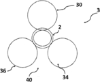
셸 측 상의 유체의 흐름은, 예를 들면, 도 4에 도시된 바와 같이, 나선형 추세(helical trend)를 가질 수도 있다. 이 경우, 스탬핑된 그리드(grid)로 제작된 특정 수의 다이어프램이 열교환기(100) 내에 설치되고, 유체가 열교환기(100)를 통해 진행하는 동안에 유체에 회전 운동을 부여하도록 경사를 이루고, 이를 통해 도 4에서 화살표로 도시된 바와 같이 셸 측 상의 유체에 전체적인 나선 운동을 생성한다.The flow of fluid on the shell side may have a helical trend, for example, as shown in FIG. In this case, a certain number of diaphragms made of a stamped grid are installed in the
종래의 TEMA형 열교환기에서 직면하는 전형적인 문제점은 유체에 의해 운반되거나 또는 다이어프램 또는 셸 측 상의 유체 경로 내의 사각 모서리(dead corner) 상에서 석출에 의해 형성되는 고형 물질의 퇴적에 의해 발생된다. 고형 물질의 퇴적은 열팽창 계수의 감소를 초래할 수 있고, 그 결과 열교환기의 성능을 감소시킬 수 있다. 또한, 열교환기 내에 퇴적된 고형 물질의 존재는 셸 측 상에서 불균일한 분포의 유체 흐름을 초래할 수 있고, 이에 따라 열교환기의 성능을 악화시킬 수 있다.A typical problem encountered in conventional TEMA heat exchangers is caused by the deposition of solid materials carried by the fluid or formed by precipitation on the dead corners in the fluid path on the diaphragm or shell side. Deposition of the solid material may result in a decrease in the coefficient of thermal expansion and, as a result, may reduce the performance of the heat exchanger. In addition, the presence of the solid material deposited in the heat exchanger can result in a non-uniform distribution of fluid flow on the shell side, thereby deteriorating the performance of the heat exchanger.
열교환기, 특히 산업용 열교환기의 분야에서, 열교환 표면을 증가시키기 위해 표면 핀을 구비한 튜브를 사용하는 것이 공지되어 있다. 셸 및 튜브형 열교환기의 경우, 성능을 셸 측 상에서 증가시킬 것인지 또는 튜브 측 상에서 증가시킬 것인지에 따라 튜브의 외면 또는 내면에 핀이 제공될 수 있다. 특수한 경우, 양면 상에 핀을 가진 튜브가 사용된다.In the field of heat exchangers, in particular industrial heat exchangers, it is known to use tubes with surface fins to increase the heat exchange surface. In the case of shell and tubular heat exchangers, a pin may be provided on the outer or inner surface of the tube depending on whether the performance is to be increased on the shell side or on the tube side. In special cases, tubes with pins on both sides are used.
종래의 열교환기(도 3에 도시된 유형의 횡방향의 주요 흐름을 가짐)에서, 통상적으로 사용되는 핀은 셸 측 상의 유체의 흐름의 주성분과의 열교환을 최대화하기 위해 튜브에 대해 횡방향이다. 셸 및 튜브형 종류(longitudinal flow) 열교환기(도 1 및 도 2에 도시된 유형)에서, 이들 횡방향 핀(즉, 진각(angle of advancement, α)=90°)은 대신에 효율을 상실할 수 있다.In a conventional heat exchanger (with a major flow in the transverse direction of the type shown in FIG. 3), the commonly used fin is transverse to the tube to maximize heat exchange with the main component of the flow of fluid on the shell side. In a shell and a longitudinal flow heat exchanger (the type shown in Figures 1 and 2), these transverse fins (i.e., angle of advancement, alpha) = 90 deg. have.
나선형 핀을 구비한 튜브, 또는 핀의 진각이 튜브의 축선에 대해 종방향 성분을 갖는 튜브(α < 90°)도 있다.There is also a tube with a helical fin, or a tube whose advancing angle of the fin has a longitudinal component with respect to the axis of the tube (α <90 °).
나선형 핀을 갖는 튜브를 제조하는 현재 공지된 방법은 나선형 핀의 수를 최대화하기 위해 여러가지 공구의 조합을 사용한다. 그러나, 핀을 가진 튜브를 제조하는 공지된 기술은 튜브를 제조하는 재료의 특성에 따라 그 적용에 한계가 있고, 따라서 핀을 제조할 수 있는 재료의 범위가 제한된다.Currently known methods of making tubes with spiral fins use a combination of tools in order to maximize the number of spiral fins. However, the known techniques for manufacturing tubes with pins have limitations in their application depending on the properties of the material from which the tube is made, thus limiting the range of materials from which the pins can be made.
실제로, 더 높은 기계적 강도를 가진 합금(즉, 스테인리스 및 이상(duplex) 강) 튜브의 존재 하에서, 핀의 형성 시에 튜브 상에 작용하는 종방향의 힘 성분은 공구들 사이에서 균일하게 분포될 수 없고, 연속적인 공구들의 작용에 의해 유발되는 재료의 점진적인 경화로 인해, 제조 중에 프로파일의 외부에서 최대 하중으로 공구의 체계적인 슬리핑(slipping)을 초래한다. 이로 인해 공구가 손상되고, 공구를 빈번하게 교체해 주어야 하며, 공구의 직접 비용 및 기계의 가동중단에 기인된 생산 부족의 면에서 손해가 발생한다.Indeed, in the presence of alloys with higher mechanical strength (i.e., stainless steel and duplex steel) tubes, longitudinal force components acting on the tube during formation of the fins can be uniformly distributed between the tools And due to gradual curing of the material caused by the action of successive tools, leads to a systematic slipping of the tool from outside the profile to maximum load during manufacture. This results in damage to the tool, frequent replacement of the tool, and loss of production due to the direct cost of the tool and the lack of production due to machine downtime.
합금 강(스테인리스 강 이상)의 존재 하에서 소정의 높이의 핀을 얻는 것을 불가능하게 하는 것은 아니지만 어렵게 만드는 경화 효과를 최소화하기 위해, 튜브는 통상적으로 2 가지 후속 기계가공 작업들 사이에서 어닐링되는데, 이는 브 생산 공정 비용을 현저히 증가시킨다.In order to minimize the hardening effect which makes it difficult, but not impossible, to obtain a pin of a predetermined height in the presence of alloy steel (stainless steel or higher), the tube is typically annealed between two subsequent machining operations, Significantly increases production process costs.
이러한 고려사항을 기반으로 하여, 본 발명의 주요 목표는 전술한 단점 및 문제점들 해결하는 셸 및 튜브형 열교환기를 제공하는 것이다.On the basis of these considerations, a main object of the present invention is to provide a shell and a tubular heat exchanger which solve the above-mentioned disadvantages and problems.
이 목표 내에서, 본 발명의 목적은 공지된 유형의 열교환기에 비해 성능이 향상된 셸 및 튜브형 종류 열교환기를 제공하는 것이다.Within this aim, it is an object of the present invention to provide a shell and tubular type heat exchanger with improved performance over known types of heat exchangers.
본 발명의 다른 목적은 종래의 열교환기에 비해 특히 셸 측 상에서 압력 강하의 단위 당 열전달 계수가 증가되는 셸 및 튜브형 종류 열교환기를 제공하는 것이다. It is another object of the present invention to provide a shell and tubular type heat exchanger in which the heat transfer coefficient per unit of pressure drop is increased, especially on the shell side compared to conventional heat exchangers.
본 발명의 또 다른 목적은 종래의 열교환기에 비해 셸 측 상 및 튜브 측 상의 둘 모두에서 압력 강하 단위 당 열전달 계수가 증가되는 셸 및 튜브형 종류 열교환기를 제공하는 것이다.It is a further object of the present invention to provide a shell and tube type heat exchanger in which the heat transfer coefficient per pressure drop unit is increased both on the shell side and on the tube side compared to the conventional heat exchanger.
본 발명의 추가의 목적은 열교환기의 성능을 향상시킬 수 있는 교환기, 특히 셸 및 튜브형 열교환기용 핀을 가진 튜브를 제공하는 것이다.It is a further object of the present invention to provide a tube having an exchanger, in particular a fin for a shell and a tubular heat exchanger, which can improve the performance of the heat exchanger.
본 발명의 다른 목적은 상기 튜브가 높은 기계적 강도를 가진 재료로 제작된 경우에도 나선형 핀(α < 90°)을 구비한 튜브의 제작을 가능하게 하는 핀을 가진 튜브를 제조하는 법을 제공하는 것이다.Another object of the present invention is to provide a method of making a tube with a fin that enables the manufacture of a tube with a helical fin (? <90 °) even when the tube is made of a material with high mechanical strength .
본 발명의 요지의 또 하나의 목적은 신뢰성이 높고 경쟁력 있는 비용으로 제조하기 쉬운 셸 및 튜브형 종류 열교환기, 및 열교환기용 핀을 가진 튜브를 제공하는 것이다.It is another object of the present invention to provide a shell and tube type heat exchanger which is easy to manufacture with high reliability and at a competitive cost, and a tube with a fin for a heat exchanger.
이하에서 보다 명확해질 이 목표, 이들 목적 및 기타 목적은 격납 케이싱 및 복수의 그리드(grid) 형상의 배플을 포함하는 셸 및 튜브형 종류 열교환기로서, 상기 격납 케이싱의 내부에서 제 1 유체가 상기 케이싱의 종축선에 대해 실질적으로 평행하게 흐를 수 있고, 상기 격납 케이싱은 그 내부에 실질적으로 서로에 대해 그리고 상기 케이싱의 종축선에 대해 평행한 튜브의 다발을 수용하고, 상기 배플은 상기 케이싱의 종축선에 대해 실질적으로 횡방향이고, 상기 배플은 상기 튜브를 지지하고, 상기 튜브의 다발은 그 내부의 제 2 유체의 흐름에 적합하도록 구성되어 있는, 셸 및 튜브형 종류 열교환기에 의해 달성되고, 본 발명에 따른 열교환기는 상기 튜브의 외면의 적어도 일부 상에는 복수의 낮은 핀이 제공되고, 상기 낮은 핀은 상기 튜브의 외면 상에 제 1 진각(angle of advancement; α)으로 나선형으로 배치되고, 상기 낮은 핀(21)은 제 2 나선형 진각(β)(α ≠ β)을 갖는 나선형 그루브가 할입(interruption)된 프로파일을 갖는 것을 특징으로 한다.These and other objects, which will become more apparent hereinafter, are a shell and a tubular type heat exchanger including a containment casing and a plurality of grid-shaped baffles, wherein a first fluid is introduced into the casing And the containment casing receives a bundle of tubes substantially parallel to one another and to the longitudinal axis of the casing within the containment casing, the baffle having a longitudinal axis extending parallel to the longitudinal axis of the casing Wherein the baffle supports the tube and the bundle of tubes is configured to fit the flow of the second fluid therein. The heat exchanger is provided with a plurality of low pins on at least a portion of an outer surface of the tube, Characterized in that the lower pin (21) has a profile in which a helical groove having a second helical advance angle (?) Is interrupted .
실제로, 이와 같이 구성된 셸 및 튜브형 종류 열교환기는 전술한 결점 및 문제점을 해결할 수 있는 일련의 특징 및 특성을 갖는다는 것이 주목되어 왔다.In fact, it has been noted that the thus configured shell and tubular type heat exchanger have a series of features and characteristics that can solve the aforementioned drawbacks and problems.
특히, 나선형 핀의 존재는 셸 측 상의 열전달 계수를 상당히 증가시킬 수 있고, 이를 통해 열교환기의 성능을 향상시킬 수 있는 것으로 밝혀졌다. In particular, it has been found that the presence of helical fins can significantly increase the heat transfer coefficient on the shell side, thereby improving the performance of the heat exchanger.
이하에서 설명되는 바와 같이 나선형 글브로 인해 핀의 프로파일 상에 파손 또는 할입(interruption)이 존재하면, 초기의 핀에 비해 열전달 면적을 더 증가시키는 3 차원 표면이 생성될 수 있다. 얻어지는 최종 표면은 3.0-4.0 배 더 크고, 심지어 초기의 매끈한 튜브에 비해 4.5 배에 도달할 수도 있다.As described below, if there is breakage or interruption on the profile of the pin due to the helical gob, a three-dimensional surface can be created that further increases the heat transfer area compared to the initial pin. The resulting final surface is 3.0-4.0 times larger and may even reach 4.5 times the initial smooth tube.
또한, 이하에서 더 잘 설명되는 바와 같이, 핀을 가진 튜브를 제조하는 특정의 방법으로 인해, 상기 방법은 또한 본 발명의 요지를 형성하며, 본 발명의 열교환기에서 전술한 이유로 중요한 높은 기계적 강도를 갖는 재료, 예를 들면, 구리-니켈, 스테인리스, 이상 강(duplex steel) 또는 타이타늄 강과 같은 합금 강으로 제조되는 핀을 가진 튜브를 사용하는 것이 가능하다.Also, as will be explained in greater detail below, due to the particular method of manufacturing tubes with fins, the method also forms the gist of the present invention and provides a significant high mechanical strength in the heat exchanger of the present invention It is possible to use a tube having a fin made of alloy steel such as copper-nickel, stainless steel, duplex steel or titanium steel.
실제로, 현재까지, 외면 상에 낮은 나선형 핀이 배치된 튜브, 특히 높은 기계적 강도를 가진 재료로 제조된 튜브를 구비하는 셸 및 튜브형 종류 열교환기는 공지되어 있지 않다.Indeed, to date, no shell and tubular type heat exchangers have been known with tubes with low spiral fins on the outer surface, especially tubes made of materials with high mechanical strength.
본 발명의 목적에서, 용어 "낮은 핀"은 약 2 mm 미만, 바람직하게는 0.5 내지 1.5 mm의 높이(H)를 갖는 핀을 의미한다.For purposes of the present invention, the term "low pin" means a pin having a height (H) of less than about 2 mm, preferably 0.5 to 1.5 mm.
핀의 진각(α)은 일반적으로 80° 미만, 바람직하게는 15° ≤ α ≤ 60°, 더 바람직하게는 20° ≤ α ≤ 45°이고, 후자는 실험적으로 증명될 수 있는 바와 같이 핀 높이와 밀도 사이의 최적의 절충을 얻기 위한 가장 좋은 범위이다.The lead angle? Of the pin is generally less than 80 占 preferably 15 占??? 60 占 more preferably 20 占?? 45 占 and the latter is the pin height It is the best range to obtain the optimum trade-off between density.
아래에서 더 잘 설명되는 바와 같이, 핀의 프로파일 상의 할입은 튜브에 상이한 진각으로 순차적으로 실시되는 2 개의 피닝(finning) 작업을 가함으로써 얻어질 수 있다.As will be explained more fully below, the profile on the profile of the pin can be obtained by applying two finishing operations to the tube, which are carried out sequentially at different lead angles.
튜브에 제 1 피닝/그루빙(finning/grooving) 공구를 이용한 제 1 그루브 기계가공 작업이 가해지고, 이 작업에 의해 재료의 경화를 제한하기 위한 얕은 깊이(바람직하게는 0.5 mm 이하) 및 진각(β)을 가진 핀이 생성된다. 이와 같이 그루브가 형성된 튜브 상에서 진각(α)을 가진 실제 핀을 생성하기 위한 제 2 주(main) 피닝 작업이 실시된다. The tube is subjected to a first groove machining operation using a first finishing / grooving tool, the depth of which shallow (preferably less than 0.5 mm) and the advance angle beta) is generated. A second main peening operation is then performed to create an actual pin with an advance angle? On the grooved tube.
이러한 방식으로, 이미 리지(ridge) 및 그루브를 가지고 있는 표면 상에 주 핀(main fin)이 생성된다. 본 방법은 제 1 피닝/그루빙 공구 및 주 피닝 공구에 대해 진각 및 피치를 사용함으로써, 주 공구의 기계가공의 결과, 보통의 원형의 매끄한 표면으로부터 시작하여 얻어질 수 있는 것에 비해 완성된 핀의 높이를 증가시킨다.In this way, a main fin is created on the surface having the ridges and grooves. By using the advancing and pitching for the first pinning / grooving tool and the main pinning tool, the method can result in machining of the main tool, as compared to what can be achieved starting from a smooth, .
특히, 주 핀 기계가공 작업은 튜브의 종축선에 대해 각도 α2 만큼 경사진 평면을 따라 실행되는 반면에 핀/그루브 기계가공 작업은 튜브의 종축선에 대해 각도 α1 만큼 경사진 평면을 따라 실행된다. 2 개의 기계가공 평면들 사이의 상대 각도(경사 각도)는 핀 높이의 가능한 최대 증가와 튜브의 종축선을 따라 측정된 단위 길이 당 획득가능한 할입의 최대수 사이의 절충에 기초하여 선택된다.In particular, the main pin machining operation is performed along a plane inclined at an angle? 2 relative to the longitudinal axis of the tube, while the pin / groove machining operation is performed along a plane inclined at an angle? 1 relative to the longitudinal axis of the tube. The relative angle (tilt angle) between the two machining planes is selected based on the trade-off between the maximum possible increase of the pin height and the maximum number of acquisitions possible per unit length measured along the longitudinal axis of the tube.
따라서 경사 각도는 0°(최대 높이 증가 및 할입 없음) 내지 90°(최소 높이 증가 및 최대 할입 효과)이다. 바람직하게는, 경사 각도는 필요에 따라 30 내지 60°이다. 이러한 방식으로, 단일 기계가공 작업에 비해 최종 핀의 높이 증가와 동시에 원하는 할입이 얻어진다.Thus, the tilt angle is 0 DEG (maximum height increase and no tilt) to 90 DEG (minimum height increase and maximum tilt effect). Preferably, the angle of inclination is 30 to 60 degrees as required. In this manner, the desired entrainment is achieved at the same time as the height of the final fin is increased compared to a single machining operation.
그루브/핀 기계가공의 2 가지 작업이 거의 동시에 실시되므로, 전술한 바와 같이, 2 개의 후속 기계가공 작업들 사이에서 튜브에 어닐링을 가하지 않으면 합금 강(스테인리스 강 이상)에서 핀 높이를 증가시키는 것을 것을 매우 어렵게 만들고, 그 결과로 비용을 증가시키는 경화 발생을 최소화시킬 수 있다.Since the two operations of groove / pin machining are carried out almost simultaneously, as described above, it is necessary to increase the fin height in the alloy steel (above stainless steel) without annealing the tube between two subsequent machining operations Making it very difficult and, as a result, minimizing the occurrence of hardening which increases the cost.
본 발명에 따른 셸 및 튜브형 열교환기에서, 상기 제 1 진각(α)과 상기 제 2 진각(β) 사이의 상대 각도는 바람직하게는 0° 내지 90°, 더 바람직하게는 30° 내지 60°이다.In the shell-and-tube heat exchanger according to the present invention, the relative angle between the first advance angle? And the second advance angle? Is preferably 0 ° to 90 °, more preferably 30 ° to 60 ° .
이와 같이 얻어질 수 있는 할입된 핀은 튜브의 전체 표면에 대해 또는 임의의 길이의 일부에 대해 연장될 수 있고, 나머지 부분은 매끈하게 남을 수 있다. 이 특징은, U 형상의 굴곡부를 가진 튜브를 사용하는 경우, 특정 용도에서 만곡된 부분을 약화시키지 않고, 그 기계적 강도를 유지시키는데 유용하다.The entrained fins thus obtainable may extend about the entire surface of the tube or about a portion of any length and the remaining portion may remain smooth. This feature is useful for maintaining the mechanical strength of a tube having a U-shaped bent portion without weakening the curved portion in a specific use.
Embaffle®형 셸 및 튜브형 종류 열교환기의 경우, 이 특징은 매끈한 부분이 배플의 안정한 위치설정을 용이하게 하므로 특히 유용하다. 이러한 이유로, 유리하게도, 본 발명에 따른 셸 및 튜브형 종류 열교환기에는 핀 부분들 사이에 매끈한 부분이 개재되는 튜브가 제공될 수 있다.In the case of Embaffle® type shell and tube type heat exchangers, this feature is particularly useful because the smooth portion facilitates stable positioning of the baffle. For this reason, advantageously, the shell and tubular type heat exchanger according to the present invention may be provided with a tube in which a smooth portion is interposed between the fin portions.
튜브 측 상에도 열전달 계수를 향상시키기 위해, 유리하게도 발명에 따른 셸 및 튜브형 종류 열교환기는 내면 상에 그루브를 형성함으로써 얻어지는 내부 핀을 가질 수 있는 튜브를 구비한다.To improve the heat transfer coefficient also on the tube side, the shell and tube type heat exchanger according to the invention advantageously has a tube which can have an inner fin which is obtained by forming a groove on the inner surface.
본 발명의 추가의 양태에서, 본 발명은 또한 제 1 가공 조립체 및 하나 이상의 지지 조립체를 포함하는 기계를 사용하여 핀을 가진 튜브를 제조하는 방법에 관한 것이다. 제 1 가공 조립체는 제 1 회전식 피닝/그루빙 공구 및 동일한 구동 축선 상에 순차적으로 장착된 제 2 회전식 피닝 공구를 포함한다. 제 1 회전식 피닝/그루빙 공구에는 제 1 진각(α1)을 갖는 제 1 나선 가공 프로파일이 제공되고, 제 2 회전식 피닝 공구에는 제 2 진각(α2)(α2≠α1)을 갖는 제 2 나선 가공 프로파일이 제공된다. In a further aspect of the present invention, the present invention also relates to a method of manufacturing a tube with a fin using a machine comprising a first processing assembly and at least one support assembly. The first machining assembly includes a first rotatable pinning / grooving tool and a second rotatable pinning tool sequentially mounted on the same drive axis. The first rotary pinning / grooving tool is provided with a first spiral machining profile having a first
본 발명에 따른 방법은 상기 지지 조립체에 의해 형성된 평면 상에서 상기 튜브를 전진시키는 단계, 상기 제 1 회전식 공구에 의해 상기 튜브 상에 (임시의) 제 1 핀/그루브를 형성하는 단계, 및 상기 제 2 회전식 공구에 의해 상기 튜브 상에 (근간의) 제 2 핀을 형성하는 단계를 포함하고, 상기 제 2 핀을 형성하는 단계는 상기 제 1 핀을 형성하는 단계의 직후에 실시되고, 또한 상기 제 1 핀의 높이는 상기 제 2 핀의 높이보다 대체로 낮다.The method according to the present invention comprises advancing the tube on a plane formed by the support assembly, forming a (temporary) first pin / groove on the tube by the first rotary tool, And forming a second fin (on a base) on the tube by a rotary tool, wherein the step of forming the second fin is performed immediately after the step of forming the first fin, The height of the pin is generally lower than the height of the second pin.
제 1 회전식 피닝/그루빙 공구의 구동 축선과 제 2 회전식 피닝 공구의 구동 축선이 튜브이 종축선에 평행인 보다 빈번한 사례에서, 제 1 진각(α1)은 상기 (임시의) 제 1 핀/그루브의 제 2 진각(β)과 동일한 값을 가지며, 제 2 진각(α2)은 (근간의) 제 2 핀의 제 1 진각(α)과 동일한 값을 갖는다. In a more frequent case where the drive axis of the first rotary pinning / grooving tool and the drive axis of the second rotary pinning tool are parallel to the longitudinal axis of the tube, the first advance angle? Has the same value as the second advance angle beta and the second
전술한 바와 같이, 상기 제 1 진각(α1)과 상기 제 2 진각(α2) 사이의 상대 각도(경사 각도)는 유리하게는 0° 내지 90°, 바람직하게는 30° 내지 60°이고, 또한, 제 1 회전식 피닝/그루빙 공구와 제 2 회전식 피닝 공구는 상기 제 1 핀의 높이(h)가 바람직하게는 0.5 mm 이하가 되도록 그리고 상기 제 2 핀의 높이(H)가 바람직하게는 0.2 mm 이하가 되도록 형성되는 것이 유리하다.As described above, the relative angle (tilt angle) between the first
또한 열교환기, 특히 본 명세서에 기술된 방법을 사용하여 얻어지는 셸 및 튜브형 열교환기를 위한 핀을 가진 튜브는 본 발명의 요지를 형성한다.Tubes with heat exchangers, particularly those for shells and tubular heat exchangers obtained using the methods described herein, form the subject of the present invention.
특히, 본 발명의 핀을 가진 튜브의 외면의 적어도 일부 상에는 복수의 낮은 핀이 제공되며, 이것은 상기 튜브의 외면 상에 제 1 진각(α)으로 나선형으로 배치되며, 제 2 진각(β)(α≠β)을 갖는 나선형 그루브가 할입된 프로파일을 가지며, 상기 진각(α)은 바람직하게는 80° 미만, 더 바람직하게는 15° ≤ α ≤ 60°이고, 상기 제 1 진각(α)과 상기 제 2 진각(β) 사이의 상대 각도는 바람직하게는 0° 내지 90°, 더 바람직하게는 30° 내지 60°이고, 상기 낮은 핀은 바람직하게는 2mm 이하, 더 바람직하게는 0.5 내지 1.5 mm의 높이(H)를 갖는다.In particular, a plurality of low pins are provided on at least a portion of an outer surface of a tube having a fin of the present invention, which is helically arranged at a first advancing angle? On the outer surface of the tube and a second advancing angle? ≠ β), and the advance angle α is preferably less than 80 °, more preferably 15 ° ≦ α ≦ 60 °, and the first advance angle α and the second advance angle α The relative angle between the two advance angles? Is preferably 0 ° to 90 °, more preferably 30 ° to 60 °, and the low pin preferably has a height of 2 mm or less, more preferably 0.5 to 1.5 mm (H).
본 발명의 추가의 특징 및 장점은 첨부 도면에서 비제한적 실시례로 도시된 본 발명에 따른 셸 및 튜브형 종류 열교환기의 바람직한 그러나 비배타적인 실시형태로부터 더 쉽게 이해될 것이다.Additional features and advantages of the present invention will become more readily apparent from the preferred but non-exclusive embodiments of the shell and tubular type heat exchanger according to the present invention shown in a non-limiting example in the accompanying drawings.
도 1은 셸 및 튜브형 종류 열교환기의 사시도를 도시하고;
도 2는 셸 및 튜브형 종류 열교환기의 개략도를 도시하고;
도 3은 셸 및 튜브형 사행 흐름 열교환기의 개략도를 도시하고;
도 4는 셸 및 튜브형 나선 흐름 열교환기의 개략도를 도시하고;
도 5는 본 발명에 따른 셸 및 튜브형 종류 열교환기에서 사용될 수 있는 핀을 가진 튜브의 일부를 도시하고;
도 6a는 본 발명에 따른 셸 및 튜브형 종류 열교환기에서 사용될 수 있는 핀을 가진 튜브의 핀들의 나선형 추세(trend)를 개략적으로 도시하고;
도 6b는 본 발명에 따른 셸 및 튜브형 종류 열교환기에서 사용될 수 있는 핀을 가진 튜브의 핀의 프로파일에 할입(interruption)되는 그루브의 나선형 추세를 개략적으로 도시하고;
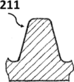
도 7a 내지 도 7c는 본 발명에 따른 셸 및 튜브형 종류 열교환기에서 사용될 수 있는 핀을 가진 튜브의 핀의 대안적인 프로파일의 단면을 도시하고;
도 8은 본 발명에 따른 셸 및 튜브형 종류 열교환기에서 사용될 수 있는 매끈한 부분이 핀 부분 내에 할입된 핀을 가진 튜브의 일부를 도시하고;
도 9는 본 발명에 따른 핀을 가진 튜브를 제조하는 방법을 구현하는 기계의 제 1 실시형태의 개략 측면도이고;
도 10은 도 9의 기계의 개략 정면도이고;
도 11a는 본 발명에 따른 핀을 가진 튜브를 제조하는 방법으로 튜브 상에 제 1 핀/그루브를 형성하는 것을 개략적으로 도시하고;
도 11b는 본 발명에 따른 핀을 가진 튜브를 제조하는 방법으로 튜브 상에 (근간의) 제 2 핀을 형성하는 것을 개략적으로 도시하고;
도 12는 본 발명에 따른 핀을 가진 튜브를 제조하는 방법을 구현하는 기계의 제 2 실시형태의 개략 측면도이고;
도 13은 도 12의 기계의 개략 정면도이고;
도 14는 본 발명에 따른 셸 및 튜브형 종류 열교환기의 개략도를 도시하고;
도 15는 도 14의 셸 및 튜브형 종류 열교환기의 세부를 도시한다.1 shows a perspective view of a shell and a tubular type heat exchanger;
Figure 2 shows a schematic view of a shell and tubular type heat exchanger;
Figure 3 shows a schematic view of a shell and tubular sheathed flow heat exchanger;
Figure 4 shows a schematic view of a shell and tubular spiral flow heat exchanger;
Figure 5 shows a portion of a tube with a fin that can be used in a shell and tubular type heat exchanger according to the present invention;
Figure 6a schematically illustrates the spiral trend of the fins of the tube with the fins that can be used in the shell and tubular type heat exchanger according to the present invention;
Figure 6b schematically illustrates the spiral trend of grooves interrupted by the profile of the fin of the tube with the fins that can be used in the shell and tubular type heat exchanger according to the present invention;
Figures 7a to 7c show cross sections of alternative profiles of the fins of tubes with fins that can be used in shell and tubular type heat exchangers according to the invention;
Figure 8 shows a portion of a tube with smooth portions that can be used in a shell and tubular type heat exchanger according to the present invention having fins inserted into the fin portion;
9 is a schematic side view of a first embodiment of a machine embodying a method of making a tube with a fin according to the present invention;
Figure 10 is a schematic front view of the machine of Figure 9;
Figure 11a schematically illustrates forming a first pin / groove on a tube in accordance with the method of making a tube with a pin according to the present invention;
Figure 11b schematically shows forming a second pin (on base) on a tube in accordance with a method of making a tube with a pin according to the present invention;
12 is a schematic side view of a second embodiment of a machine implementing a method of making a tube with a fin according to the present invention;
Figure 13 is a schematic front view of the machine of Figure 12;
Figure 14 shows a schematic view of a shell and tubular type heat exchanger according to the present invention;
Figure 15 shows details of the shell and tubular type heat exchanger of Figure 14;
첨부한 도면을 참조하면, EMBaffle® 유형의 셸 및 튜브형 종류 열교환기는 더욱 일반적인 실시형태에서 격납 케이싱(101)을 포함하고, 그 내부에서 제 1 유체가 상기 케이싱(101)의 종축선에 대해 실질적으로 평행하게 흐를 수 있다.Referring to the attached drawings, the shell and tubular type heat exchanger of the EMBaffle (R) type includes a
격납 케이싱(101) 내부에는 튜브(2)의 다발이 위치되어 있고, 이 튜브(2)의 다발은 서로에 대해, 그리고 케이싱(101)의 종축선에 대해 실질적으로 평행하고, 이 케이싱(101)은 또한 상기 케이싱(101)의 종축선에 대해 횡방향의 복수의 그리드 형상의 배플(102)을 포함하고, 상기 배플(102)은 상기 튜브(2)를 지지한다. A bundle of
특히 도 14를 참조하면, 제 2 유체는 셸(101) 내부의 제 1 유체의 흐름 방향(화살표(110) 참조)에 대해 대체적으로 대향류로 튜브(2)의 내부에서 흐른다(화살표(210) 참조).14, the second fluid flows in the interior of the tube 2 (arrow 210) in a generally counter-current direction relative to the flow direction of the first fluid (see arrow 110) inside the
도 7을 참조하면, 본 발명에 따른 셸 및 튜브형 종류 열교환기(1)의 고유의 특징들 중 하나는 상기 튜브(2)의 외면의 적어도 일부 상에는 제 1 진각(α)에 따라 상기 튜브(2)의 외면 상에 나선형으로 배치되는 복수의 낮은 핀(21)이 제공되는 것이다. 이 진각(α)은 일반적으로 80° 미만, 바람직하게는 15° 내지 60°, 더 바람직하게는 20° 내지 45°이다.7, one of the unique characteristics of the shell and tubular
본 발명에 따른 셸 및 튜브형 종류 열교환기(1)의 추가의 고유의 특징은 낮은 핀(21)이 제 2 진각(β)(α≠β)을 갖는 나선형 그루브(22)에 의해 할입된 프로파일을 갖는 것이다.A further unique feature of the shell and tubular
튜브(2)의 특징을 더 명확하게 도시하기 위해, 도 6a 및 도 6b에서는 개략적으로 핀과 그루브가 개별적으로 도시되어 있다. 또한 도 11a를 참조하면, 튜브(2)의 제 1 기계가공 단계로 인해 튜브의 베이스는 (h의 양 만큼) 하강 및 (동일한 h의 양만큼) 상승될 수 있으므로 나선형 핀(22) 및 도 6b에 도시된 바와 같은 진각(β)을 갖는 대응하는 나선형 그루브를 갖는 파형 프로파일을 형성할 수 있다. 베이스 프로파일에 관한 높이(h)는 바람직하게는 0.5 mm 미만이다.To more clearly illustrate the features of the
이제 도 11b를 참조하면, 튜브(2)의 제 2 기계가공 단계로 인해 진각(α)(도 6a 참조)으로 나선형 기계가공 작업에 따라 도 11a의 튜브(2)의 파형 프로파일을 (H의 양 만큼) 하강 및 (동일한 H의 양만큼) 상승시킴으로써 최종 핀(21)이 얻어질 수 있다. Referring now to FIG. 11B, the second machining step of the
높이 및 할입의 수의 관점에서 핀(21)의 최종 구조는 2 개의 변형의 구성, 특히 h 및 H의 양 및 각도 α 및 β에 의존한다. α와 β 사이의 상대 각도가 0°에 근접하는 경우, 핀(21)의 높이의 최대 증가가 얻어지고, 반면에 이것인 90°에 근접하는 경우, 그루브(22)로 인해 핀(21)의 프로파일 상에 최대 수의 할입이 얻어진다.The final structure of the
핀(21)의 "형상"에 관하여 이것은 필요에 따라 자유롭게 선택될 수 있다. 도 7a 내지 도 7c는 핀(21)의 일부의 가능한 단면을 도시한 것이며, 결코 이들 실시형태에 제한되는 것은 아니다.With respect to the "shape" of the
도 8를 참조하면, 본 발명에 따른 셸 및 튜브형 종류 열교환기(1)의 바람직한 실시형태에서, 튜브(2)에는 매끈한 부분(200)이 개재된 핀 부분(20)이 제공된다. 이러한 방식으로, 또한 도 15를 참조하면, 배플(102)의 안정된 위치설정이 용이해진다.Referring to Fig. 8, in a preferred embodiment of the shell and tubular
이제 도 9 및 도 10을 참조하여 외면의 하나 이상의 부분 상에 복수의 낮은 핀을 구비하는 핀을 가진 튜브(2)를 제조하는 방법의 제 1 실시형태를 설명한다. 이들 핀(21)은 제 1 진각(α)으로 상기 외면 상에 나선형으로 배치되고, 제 2 진각(β)을 가진 나선형 그루브(22)가 할입된 프로파일을 갖는다.Referring now to Figures 9 and 10, a first embodiment of a method of manufacturing a
본 발명에 따른 방법은 가공 조립체(30) 및 하나 이상의 지지 조립체(40)를 포함하는 기계(3)를 사용하여 실시된다. 제 1 가공 조립체(30)는 제 1 회전식 피닝/그루빙 공구(32) 및 동일한 구동 축선(33) 상에 순차적으로 장착된 제 2 회전식 피닝 공구(31)를 포함한다. 지지 조립체(40)는 2 개의 매끈한 표면의 원통형 가이드(34, 36)를 포함하고, 이것의 목적은 기계가공 중에 튜브(2)를 정위치에 유지시키고, 가공 조립체(30)의 스러스트 하중(thrust load)을 지지하는 것이다.The method according to the invention is carried out using a
제 1 회전식 피닝/그루빙 공구(32)는 튜브(2)의 외면 상에 형성되는 제 1 진각(α1)을 갖는 나선형 그루브(22)에 대칭인 제 1 나선 가공 프로파일를 구비한다. The first rotary pinning /
제 2 회전식 피닝 공구(31)는 튜브(2)의 외면 상에 형성되는 제 2 진각(α2)(α2≠α1)을 갖는 낮은 핀(21)에 대칭인 제 2 나선 가공 프로파일를 구비한다.The second
본 발명에 따른 방법은 지지 조립체(40)에 의해 형성되는 평면 상에서 튜브(2)를 전진시키는 단계 및 제 1 회전식 공구(32)에 의해 상기 튜브(2) 상에 제 1 핀/그루브(22)를 형성하는 단계를 포함한다. 유리하게는, 핀/그루브(22)는 재료의 경화를 제한하기 위해 바람직하게는 0.5 mm 이하의 깊이를 갖는다.The method according to the present invention comprises the steps of advancing the
제 1 핀/그루브(22)가 형성된 직후에 제 2 핀(21)(주 핀)이 상기 제 2 회전식 피닝 공구(31)에 의해 상기 튜브(2) 상에 형성된다. 상기 주 핀인 제 2 핀(21)의 높이는 통상적으로 2 mm 미만이지만 상기 제 1 핀(22)의 높이보다 높다.A second pin 21 (main pin) is formed on the
전술한 바와 같이, 상기 제 1 진각(α1)과 상기 제 2 진각(α2) 사이의 상대 각도에 의존하여, 더 높거나 더 낮은 주 핀(21)의 높이를 얻을 수 있고, 그루브(22)에 의한 더 많거나 더 적은 수의 할입을 얻을 수 있다.A higher or lower height of the
도 12 및 도 13을 참조하면, 본 발명에 따른 핀을 가진 튜브(2)를 제조하는 방법의 제 2 실시형태에서, 튜브의 외면과 내면의 둘 모두에 복수의 낮은 핀이 형성된다. Referring to Figures 12 and 13, in a second embodiment of the method of manufacturing a tube (2) with a fin according to the present invention, a plurality of lower pins are formed on both the outer and inner surfaces of the tube.
이 경우, 본 발명에 따른 방법은 전술한 제 1 가공 조립체(30) 및 지지 조립체(40)와 유사한 제 1 가공 조립체(50) 및 지지 조립체(70)를 포함하는 기계(5)를 사용하여 실시된다. 튜브(2)의 외부 부분에 관련하여, 기계가공은 전술한 것과 동일한 방식으로 실시된다.In this case the method according to the invention is carried out using a
이 기계(5)는 또한 튜브(2)의 내부 핀을 형성하도록 구성된 제 2 가공 조립체를 포함한다. 내부 핀은 튜브(2)의 내면 상에서 얻어지도록 된 것과 대칭인 프로파일을 갖는 피닝 공구(61)에 의해 얻어진다. 공구(61)는 튜브 내에 삽입되고, 지지 조립체(70)의 매끈한 표면의 원통형 가이드(71, 72) 상에 지지되어 있는 튜브(2) 상에 제 1 회전식 공구(32) 및 제 2 회전식 공구(31)에 의해 가해지는 압력에 이해 "작동"된다. 이로 인해 튜브(2)의 내경은 감소되고, 이에 따라 내부 공구(61)에 의해 피닝된다.The machine (5) also includes a second processing assembly configured to form the inner pins of the tube (2). The inner pin is obtained by a pinning
내부 핀은 외부 공구 또는 내부 공구가 속박되는 것을 방지하기 위해 외부 핀(21)의 것과 반대인 워프 각도(wrap angle)를 갖는다. 내부 부분의 진각, 핀의 높이 및 핀의 밀도는 종래 기술에서 공지된 범위 내에서 얻어질 수 있다.The inner pin has a wrap angle opposite to that of the
요컨대, 개시된 본 방법은 저합금강 또는 고합금강으로 제조된 튜브의 외부(또는 외부 및 내부)의 냉간 성형을 위해 2 개의 프로파일을 갖는 공구를 사용한다. 이한 구성은 높은 생산성을 가능하게 하고, 빈번한 공구의 손상/파손의 위험을 방지하고, 사용되는 기계적 장치의 복잡성을 최소로 감소시킨다. 또한 종래 기술로부터 공지된 바와 같이, 많은 대안적 방법에서 중요한 구리-니켈, 스테인리스, 이상, 타이타늄 강과 같은 합금 강의 기계가공을 위해 적합할 수 있다.In short, the disclosed method uses a tool having two profiles for cold forming (either external or internal) of a tube made of low alloy steel or high alloy steel. This configuration enables high productivity, avoids the risk of frequent tool damage / breakage, and minimizes the complexity of the mechanical devices used. It may also be suitable for the machining of alloy steels such as copper-nickel, stainless steel, ideal, titanium steels, which are important in many alternative methods, as is known from the prior art.
전술한 설명에 기초하면, 핀을 가진 튜브를 제조하는 방법, 이에 따라 얻어지는 핀을 가진 튜브, 및 열교환기, 특히 본 발명에 따른 셸 및 튜브형 종류 열교환기가 의도된 목표 및 목적을 달성하는 방법이 밝혀졌다.Based on the above description, it has been revealed how to make tubes with fins, tubes with the resulting fins, and heat exchangers, in particular the shell and tube type heat exchangers according to the invention, to achieve the intended goals and objectives lost.
제공된 설명에 기초하여 다른 특징, 수정, 또는 개선이 가능하고, 이는 당업자에게 명백하다. 따라서, 이들 특징, 수정 및 개선은 본 발명의 일부로 간주되어야 한다. 실제로, 사용되는 재료, 치수 및 부수적 형상은 요구사양 및 종래 기술에 따라 임의로 선택될 수 있다. Other features, modifications, or improvements are possible, based on the description provided, as will be apparent to those skilled in the art. Accordingly, these features, modifications, and improvements should be considered part of the present invention. Indeed, the materials, dimensions and minor shapes used may be arbitrarily selected according to the requirements and prior art.
Claims (10)
상기 격납 케이싱(101)의 내부에서 제 1 유체가 상기 케이싱(101)의 종축선에 대해 실질적으로 평행하게 흐를 수 있고, 상기 격납 케이싱(101)은 그 내부에 실질적으로 서로에 대해 그리고 상기 케이싱(101)의 종축선에 대해 평행한 튜브(2)의 다발을 수용하고,
상기 배플(102)은 상기 케이싱(101)의 종축선에 대해 실질적으로 횡방향이고, 상기 배플(102)은 상기 튜브(2)를 지지하고, 상기 튜브(2)의 다발은 그 내부의 제 2 유체의 흐름에 적합하도록 구성되어 있고,
상기 튜브(2)의 외면의 적어도 일부 상에는 복수의 낮은 핀(21)이 제공되고, 상기 낮은 핀(21)은 상기 튜브(2)의 외면 상에 제 1 진각(angle of advancement; α)으로 나선형으로 배치되고, 상기 낮은 핀(21)은 제 2 나선형 진각(β)(α ≠ β)을 갖는 나선형 그루브(22)가 할입(interruption)된 프로파일을 갖는,
셸 및 튜브형 종류 열교환기.A shell and tube longitudinal flow heat exchanger (1) comprising a containment casing (101) and a plurality of grid-shaped baffles (102)
The first fluid can flow substantially parallel to the longitudinal axis of the casing 101 inside the containment casing 101 and the containment casing 101 can be moved substantially inside the casing 101 101 parallel to the longitudinal axis of the tube 2,
The baffle 102 is substantially transverse to the longitudinal axis of the casing 101 and the baffle 102 supports the tube 2 and the bundle of tubes 2 has a second Which is adapted to the flow of the fluid,
A plurality of low pins 21 are provided on at least a part of the outer surface of the tube 2 and the low pins 21 are arranged on the outer surface of the tube 2 in a spiral shape with a first angle of advance And the lower pin 21 is arranged with a spiral groove 22 having a second spiral advance angle?
Shell and tube type heat exchanger.
상기 낮은 핀(21)은 2 mm 이하, 바람직하게는 0.5 내지 1.5 mm의 높이(H)를 갖는,
셸 및 튜브형 종류 열교환기(1).The method according to claim 1,
The lower pin 21 has a height H of 2 mm or less, preferably 0.5 to 1.5 mm,
Shell and tube type heat exchanger (1).
상기 제 1 진각(α)은 80° 미만, 바람직하게는 15° ≤ α ≤ 60°, 더 바람직하게는 20° ≤ α ≤ 45°인,
셸 및 튜브형 종류 열교환기(1). The method according to claim 1,
Wherein the first advance angle? Is less than 80 °, preferably 15 °??? 60 °, more preferably 20 °??? 45 °,
Shell and tube type heat exchanger (1).
상기 제 1 진각(α)과 상기 제 2 진각(β) 사이의 상대 각도는 0° 내지 90°, 바람직하게는 30° 내지 60°인,
셸 및 튜브형 종류 열교환기(1).4. The method according to any one of claims 1 to 3,
Wherein a relative angle between the first advancing angle alpha and the second advancing angle beta is from 0 DEG to 90 DEG and preferably from 30 DEG to 60 DEG,
Shell and tube type heat exchanger (1).
상기 튜브(2)의 내면 상에는 복수의 낮은 핀이 제공되는,
셸 및 튜브형 종류 열교환기(1).5. The method according to any one of claims 1 to 4,
Wherein a plurality of low pins are provided on the inner surface of the tube (2)
Shell and tube type heat exchanger (1).
상기 튜브(2)에는 매끈한 부분(200)이 개재되는 핀 부분(20)이 제공되는,
셸 및 튜브형 종류 열교환기(1).6. The method according to any one of claims 1 to 5,
Wherein the tube (2) is provided with a fin portion (20) in which a smooth portion (200)
Shell and tube type heat exchanger (1).
상기 방법은 상기 지지 조립체(40, 70)에 의해 형성되는 평면 상에서 상기 튜브(2)를 전진시키는 단계, 상기 제 1 회전식 피닝 공구(32)에 의해 상기 튜브(2) 상에 제 1 핀(22)을 형성하는 단계, 및 상기 제 2 회전식 피닝 공구(31)에 의해 상기 튜브(2) 상에 제 2 핀(21)을 형성하는 단계를 포함하고,
상기 제 2 핀(21)의 형성은 상기 제 2 핀(21)의 형성의 직후에 실시되고, 상기 제 1 핀(22)의 높이는 상기 제 2 핀(21)의 높이보다 낮은,
핀을 가진 튜브를 제조하는 방법.(30, 50) comprises a first rotary pinning tool (32) and a second rotary pinion tool (32) on the same drive axis (33), wherein the processing assembly (30, 50) and the at least one support assembly , Wherein the first rotary pinning tool (32) is provided with a first spiral working profile having a first advance angle (? 1), and the second rotary pinning tool (31) Is a method for manufacturing a tube (2) with a fin using a machine (3, 5) provided with a second spirally processed profile having a second advance angle (? 2) (? 2?
The method includes advancing the tube (2) on a plane defined by the support assembly (40,70), positioning the first pin (22) on the tube (2) by the first rotary pinning tool ) And forming a second pin (21) on the tube (2) by means of the second rotary pinning tool (31)
The formation of the second fin 21 is performed immediately after the formation of the second fin 21 and the height of the first fin 22 is lower than the height of the second fin 21,
A method of manufacturing a tube having a fin.
상기 제 1 진각(α1)과 상기 제 2 진각(α2) 사이의 상대 각도는 0° 내지 90°, 바람직하게는 30° 내지 60°이고, 상기 제 1 핀의 높이(h)는 0.5 mm 이하이고, 상기 제 2 핀의 높이(H)는 2 mm 이하인,
핀을 가진 튜브를 제조하는 방법.8. The method of claim 7,
The relative angle between the first advance angle alpha 1 and the second advance angle alpha 2 is 0 to 90 degrees and preferably 30 to 60 degrees and the height h of the first fin is 0.5 mm or less , The height (H) of the second fin is not more than 2 mm,
A method of manufacturing a tube having a fin.
핀을 가진 튜브(2).10. A heat exchanger for a heat exchanger (1, 10, 100) obtained according to claim 7 or 8, in particular for a shell and tube heat exchanger (1)
Tubes with pins (2).
상기 핀을 가진 튜브(2)의 외면의 적어도 일부 상에는 복수의 낮은 핀(21)이 제공되고, 상기 낮은 핀(21)은 상기 튜브(2)의 외면 상에 제 1 진각(α)으로 나선형으로 배치되고, 상기 낮은 핀(21)은 제 2 나선형 진각(β)(α ≠ β)을 가진 나선형 그루브(22)가 할입되는 프로파일을 가지며, 상기 제 1 진각(α)은 바람직하게는 80° 미만, 더 바람직하게는 15° ≤ α ≤ 60°이고, 상기 제 1 진각(α)과 상기 제 2 진각(β) 사이의 상대 각도는 바람직하게는 0° 내지 90°, 더 바람직하게는 30° 내지 60°이고, 상기 낮은 핀(21)은 바람직하게는 2 mm 이하, 더 바람직하게는 0.5 내지 1.5 mm의 높이(H)를 갖는,
핀을 가진 튜브(2).10. The method of claim 9,
A plurality of low pins 21 are provided on at least a part of the outer surface of the tube 2 with the pins and the low pins 21 are spirally arranged on the outer surface of the tube 2 at a first advance angle? And the lower pin 21 has a profile in which a helical groove 22 having a second helical advance angle beta (?? Beta) is inserted and the first advance angle alpha is preferably less than 80 degrees , More preferably 15 ° ≤ α ≤ 60 ° and the relative angle between the first advance angle α and the second advance angle β is preferably 0 ° to 90 °, 60 占 and the lower pin 21 has a height H of preferably 2 mm or less, more preferably 0.5 to 1.5 mm,
Tubes with pins (2).
Applications Claiming Priority (3)
| Application Number | Priority Date | Filing Date | Title |
|---|---|---|---|
| IT102015000086994 | 2015-12-23 | ||
| ITUB2015A009298A ITUB20159298A1 (en) | 2015-12-23 | 2015-12-23 | Shell and tube heat exchanger and shell, finned tubes for this exchanger and relative production method. |
| PCT/EP2016/078809 WO2017108330A1 (en) | 2015-12-23 | 2016-11-25 | Shell and tube heat exchanger, finned tubes for such heat exchanger and corresponding method |
Publications (1)
| Publication Number | Publication Date |
|---|---|
| KR20180098304A true KR20180098304A (en) | 2018-09-03 |
Family
ID=55697346
Family Applications (1)
| Application Number | Title | Priority Date | Filing Date |
|---|---|---|---|
| KR1020187020540A KR20180098304A (en) | 2015-12-23 | 2016-11-25 | Shell and tubular heat exchangers, tubes with these heat exchanger pins, and corresponding methods |
Country Status (9)
| Country | Link |
|---|---|
| US (2) | US20180372427A1 (en) |
| EP (1) | EP3394550B1 (en) |
| JP (1) | JP2019502084A (en) |
| KR (1) | KR20180098304A (en) |
| CN (1) | CN108431538A (en) |
| DK (1) | DK3394550T3 (en) |
| ES (1) | ES2944546T3 (en) |
| IT (1) | ITUB20159298A1 (en) |
| WO (1) | WO2017108330A1 (en) |
Families Citing this family (3)
| Publication number | Priority date | Publication date | Assignee | Title |
|---|---|---|---|---|
| CN109489456A (en) * | 2018-11-28 | 2019-03-19 | 江阴市森博特种换热设备有限公司 | A kind of silicon carbide tubular heat exchanger of high heat exchange efficiency |
| CA3195755A1 (en) * | 2020-11-17 | 2022-05-27 | Harald GAIBLER | Tube bundle heat exchanger |
| CN115397184A (en) * | 2021-05-25 | 2022-11-25 | 英业达科技有限公司 | Electronic device and heat dissipation assembly |
Family Cites Families (13)
| Publication number | Priority date | Publication date | Assignee | Title |
|---|---|---|---|---|
| GB1359647A (en) * | 1971-10-12 | 1974-07-10 | Dewandre Co Ltd C | Heat transfer tubes |
| US4660630A (en) * | 1985-06-12 | 1987-04-28 | Wolverine Tube, Inc. | Heat transfer tube having internal ridges, and method of making same |
| US5141049A (en) * | 1990-08-09 | 1992-08-25 | The Badger Company, Inc. | Treatment of heat exchangers to reduce corrosion and by-product reactions |
| CN1084876C (en) * | 1994-08-08 | 2002-05-15 | 运载器有限公司 | Heat transfer tube |
| EP0713072B1 (en) * | 1994-11-17 | 2002-02-27 | Carrier Corporation | Heat transfer tube |
| US5697430A (en) * | 1995-04-04 | 1997-12-16 | Wolverine Tube, Inc. | Heat transfer tubes and methods of fabrication thereof |
| CA2230213C (en) * | 1997-03-17 | 2003-05-06 | Xin Liu | A heat transfer tube and method of manufacturing same |
| US5933953A (en) * | 1997-03-17 | 1999-08-10 | Carrier Corporation | Method of manufacturing a heat transfer tube |
| US6176302B1 (en) * | 1998-03-04 | 2001-01-23 | Kabushiki Kaisha Kobe Seiko Sho | Boiling heat transfer tube |
| US6182743B1 (en) * | 1998-11-02 | 2001-02-06 | Outokumpu Cooper Franklin Inc. | Polyhedral array heat transfer tube |
| US6176301B1 (en) * | 1998-12-04 | 2001-01-23 | Outokumpu Copper Franklin, Inc. | Heat transfer tube with crack-like cavities to enhance performance thereof |
| CN100437011C (en) * | 2005-12-13 | 2008-11-26 | 金龙精密铜管集团股份有限公司 | Flooded copper-evaporating heat-exchanging pipe for electric refrigerator set |
| DE102006008083B4 (en) * | 2006-02-22 | 2012-04-26 | Wieland-Werke Ag | Structured heat exchanger tube and method for its production |
-
2015
- 2015-12-23 IT ITUB2015A009298A patent/ITUB20159298A1/en unknown
-
2016
- 2016-11-25 US US16/063,378 patent/US20180372427A1/en not_active Abandoned
- 2016-11-25 CN CN201680074849.0A patent/CN108431538A/en active Pending
- 2016-11-25 EP EP16810268.9A patent/EP3394550B1/en active Active
- 2016-11-25 WO PCT/EP2016/078809 patent/WO2017108330A1/en active Application Filing
- 2016-11-25 DK DK16810268.9T patent/DK3394550T3/en active
- 2016-11-25 JP JP2018533675A patent/JP2019502084A/en active Pending
- 2016-11-25 KR KR1020187020540A patent/KR20180098304A/en not_active Application Discontinuation
- 2016-11-25 ES ES16810268T patent/ES2944546T3/en active Active
-
2020
- 2020-10-20 US US17/074,740 patent/US20210033351A1/en not_active Abandoned
Also Published As
| Publication number | Publication date |
|---|---|
| CN108431538A (en) | 2018-08-21 |
| DK3394550T3 (en) | 2023-05-01 |
| US20180372427A1 (en) | 2018-12-27 |
| JP2019502084A (en) | 2019-01-24 |
| ITUB20159298A1 (en) | 2017-06-23 |
| US20210033351A1 (en) | 2021-02-04 |
| WO2017108330A1 (en) | 2017-06-29 |
| EP3394550B1 (en) | 2023-04-05 |
| EP3394550A1 (en) | 2018-10-31 |
| ES2944546T3 (en) | 2023-06-22 |
Similar Documents
| Publication | Publication Date | Title |
|---|---|---|
| US20210033351A1 (en) | Shell and tube heat exchanger, finned tubes for such heat exchanger and corresponding method | |
| US6488078B2 (en) | Heat-exchanger tube structured on both sides and a method for its manufacture | |
| EP2232187B1 (en) | Heat transfer tube | |
| CA1150723A (en) | Heat transfer surface and method of manufacture | |
| JP5376763B2 (en) | Heat exchanger tube | |
| US20050241150A1 (en) | Method of manufacture of heat-exchanger tube structured on both sides | |
| BRPI1005860A2 (en) | heat transmission tube and process for the manufacture of a heat transmission tube | |
| WO2012117440A1 (en) | Heat exchanger, refrigerator with the heat exchanger, and air conditioner with the heat exchanger | |
| EP2917674B1 (en) | Evaporation heat transfer tube with a hollow cavity | |
| EP3406997B1 (en) | Entwined tubular arrangements for heat exchangers and counterflow heat transfer systems | |
| JP2011106746A (en) | Heat transfer tube, heat exchanger, and processed product of heat transfer tube | |
| JP2005257160A (en) | Heat transfer pipe with grooved inner surface and heat exchanger using the heat transfer tube with grooved inner surface | |
| JP4913371B2 (en) | Manufacturing method of heat exchanger | |
| EP3218664B1 (en) | Fin for a finned pack for heat exchangers, as well as heat exchanger | |
| EP2735386A2 (en) | Heat exchanger and method for manufacturing same | |
| JP5289088B2 (en) | Heat exchanger and heat transfer tube | |
| JP2012200769A (en) | Flat tube for heat exchanger and method of manufacture the same | |
| Tangsri et al. | Influences of total reduction of area on drawing stress and tube dimension in inner spiral ribbed copper tube sinking | |
| JP2004322141A (en) | Hairpin bent copper tube and hairpin bending method for copper tube | |
| CN104251632B (en) | Twisted piece finned tube and finned tube heat-exchanging tube bundle thereof | |
| US11156382B2 (en) | C-shaped heat exchanger tube and nested bundle of C-shaped heat exchanger tubes | |
| JP2010133581A (en) | Inner helically grooved tube for heat pipe and the heat pipe | |
| JP2009246290A (en) | Tube with groove on inner surface for heat pipe, and heat pipe | |
| CN106643259A (en) | Composite tooth-shaped internal thread copper pipe structure | |
| JP2003062610A (en) | Manufacturing method for heat exchanger tube with inclined fin inside |
Legal Events
| Date | Code | Title | Description |
|---|---|---|---|
| E902 | Notification of reason for refusal | ||
| E601 | Decision to refuse application |