KR20170139615A - Graded diffuser - Google Patents
Graded diffuser Download PDFInfo
- Publication number
- KR20170139615A KR20170139615A KR1020177033657A KR20177033657A KR20170139615A KR 20170139615 A KR20170139615 A KR 20170139615A KR 1020177033657 A KR1020177033657 A KR 1020177033657A KR 20177033657 A KR20177033657 A KR 20177033657A KR 20170139615 A KR20170139615 A KR 20170139615A
- Authority
- KR
- South Korea
- Prior art keywords
- turbidity
- diffuser
- structured
- optical
- major surface
- Prior art date
Links
Images


Classifications
-
- G—PHYSICS
- G02—OPTICS
- G02B—OPTICAL ELEMENTS, SYSTEMS OR APPARATUS
- G02B5/00—Optical elements other than lenses
- G02B5/02—Diffusing elements; Afocal elements
- G02B5/0205—Diffusing elements; Afocal elements characterised by the diffusing properties
- G02B5/021—Diffusing elements; Afocal elements characterised by the diffusing properties the diffusion taking place at the element's surface, e.g. by means of surface roughening or microprismatic structures
- G02B5/0221—Diffusing elements; Afocal elements characterised by the diffusing properties the diffusion taking place at the element's surface, e.g. by means of surface roughening or microprismatic structures the surface having an irregular structure
-
- G—PHYSICS
- G02—OPTICS
- G02B—OPTICAL ELEMENTS, SYSTEMS OR APPARATUS
- G02B5/00—Optical elements other than lenses
- G02B5/02—Diffusing elements; Afocal elements
-
- C—CHEMISTRY; METALLURGY
- C25—ELECTROLYTIC OR ELECTROPHORETIC PROCESSES; APPARATUS THEREFOR
- C25D—PROCESSES FOR THE ELECTROLYTIC OR ELECTROPHORETIC PRODUCTION OF COATINGS; ELECTROFORMING; APPARATUS THEREFOR
- C25D3/00—Electroplating: Baths therefor
- C25D3/02—Electroplating: Baths therefor from solutions
- C25D3/04—Electroplating: Baths therefor from solutions of chromium
-
- C—CHEMISTRY; METALLURGY
- C25—ELECTROLYTIC OR ELECTROPHORETIC PROCESSES; APPARATUS THEREFOR
- C25D—PROCESSES FOR THE ELECTROLYTIC OR ELECTROPHORETIC PRODUCTION OF COATINGS; ELECTROFORMING; APPARATUS THEREFOR
- C25D3/00—Electroplating: Baths therefor
- C25D3/02—Electroplating: Baths therefor from solutions
- C25D3/38—Electroplating: Baths therefor from solutions of copper
-
- C—CHEMISTRY; METALLURGY
- C25—ELECTROLYTIC OR ELECTROPHORETIC PROCESSES; APPARATUS THEREFOR
- C25D—PROCESSES FOR THE ELECTROLYTIC OR ELECTROPHORETIC PRODUCTION OF COATINGS; ELECTROFORMING; APPARATUS THEREFOR
- C25D5/00—Electroplating characterised by the process; Pretreatment or after-treatment of workpieces
- C25D5/10—Electroplating with more than one layer of the same or of different metals
- C25D5/12—Electroplating with more than one layer of the same or of different metals at least one layer being of nickel or chromium
-
- C—CHEMISTRY; METALLURGY
- C25—ELECTROLYTIC OR ELECTROPHORETIC PROCESSES; APPARATUS THEREFOR
- C25D—PROCESSES FOR THE ELECTROLYTIC OR ELECTROPHORETIC PRODUCTION OF COATINGS; ELECTROFORMING; APPARATUS THEREFOR
- C25D5/00—Electroplating characterised by the process; Pretreatment or after-treatment of workpieces
- C25D5/60—Electroplating characterised by the structure or texture of the layers
- C25D5/605—Surface topography of the layers, e.g. rough, dendritic or nodular layers
-
- C—CHEMISTRY; METALLURGY
- C25—ELECTROLYTIC OR ELECTROPHORETIC PROCESSES; APPARATUS THEREFOR
- C25D—PROCESSES FOR THE ELECTROLYTIC OR ELECTROPHORETIC PRODUCTION OF COATINGS; ELECTROFORMING; APPARATUS THEREFOR
- C25D7/00—Electroplating characterised by the article coated
-
- G—PHYSICS
- G02—OPTICS
- G02B—OPTICAL ELEMENTS, SYSTEMS OR APPARATUS
- G02B1/00—Optical elements characterised by the material of which they are made; Optical coatings for optical elements
- G02B1/10—Optical coatings produced by application to, or surface treatment of, optical elements
- G02B1/11—Anti-reflection coatings
- G02B1/113—Anti-reflection coatings using inorganic layer materials only
- G02B1/115—Multilayers
-
- G—PHYSICS
- G02—OPTICS
- G02B—OPTICAL ELEMENTS, SYSTEMS OR APPARATUS
- G02B1/00—Optical elements characterised by the material of which they are made; Optical coatings for optical elements
- G02B1/10—Optical coatings produced by application to, or surface treatment of, optical elements
- G02B1/14—Protective coatings, e.g. hard coatings
-
- G—PHYSICS
- G02—OPTICS
- G02B—OPTICAL ELEMENTS, SYSTEMS OR APPARATUS
- G02B3/00—Simple or compound lenses
- G02B3/0006—Arrays
- G02B3/0037—Arrays characterized by the distribution or form of lenses
- G02B3/005—Arrays characterized by the distribution or form of lenses arranged along a single direction only, e.g. lenticular sheets
-
- G—PHYSICS
- G02—OPTICS
- G02B—OPTICAL ELEMENTS, SYSTEMS OR APPARATUS
- G02B3/00—Simple or compound lenses
- G02B3/0006—Arrays
- G02B3/0037—Arrays characterized by the distribution or form of lenses
- G02B3/0062—Stacked lens arrays, i.e. refractive surfaces arranged in at least two planes, without structurally separate optical elements in-between
-
- G—PHYSICS
- G02—OPTICS
- G02B—OPTICAL ELEMENTS, SYSTEMS OR APPARATUS
- G02B5/00—Optical elements other than lenses
- G02B5/02—Diffusing elements; Afocal elements
- G02B5/0205—Diffusing elements; Afocal elements characterised by the diffusing properties
- G02B5/0236—Diffusing elements; Afocal elements characterised by the diffusing properties the diffusion taking place within the volume of the element
- G02B5/0242—Diffusing elements; Afocal elements characterised by the diffusing properties the diffusion taking place within the volume of the element by means of dispersed particles
-
- G—PHYSICS
- G02—OPTICS
- G02B—OPTICAL ELEMENTS, SYSTEMS OR APPARATUS
- G02B5/00—Optical elements other than lenses
- G02B5/02—Diffusing elements; Afocal elements
- G02B5/0205—Diffusing elements; Afocal elements characterised by the diffusing properties
- G02B5/0263—Diffusing elements; Afocal elements characterised by the diffusing properties with positional variation of the diffusing properties, e.g. gradient or patterned diffuser
-
- G—PHYSICS
- G02—OPTICS
- G02B—OPTICAL ELEMENTS, SYSTEMS OR APPARATUS
- G02B5/00—Optical elements other than lenses
- G02B5/02—Diffusing elements; Afocal elements
- G02B5/0268—Diffusing elements; Afocal elements characterized by the fabrication or manufacturing method
-
- G—PHYSICS
- G02—OPTICS
- G02B—OPTICAL ELEMENTS, SYSTEMS OR APPARATUS
- G02B5/00—Optical elements other than lenses
- G02B5/02—Diffusing elements; Afocal elements
- G02B5/0273—Diffusing elements; Afocal elements characterized by the use
- G02B5/0278—Diffusing elements; Afocal elements characterized by the use used in transmission
-
- G—PHYSICS
- G02—OPTICS
- G02B—OPTICAL ELEMENTS, SYSTEMS OR APPARATUS
- G02B5/00—Optical elements other than lenses
- G02B5/02—Diffusing elements; Afocal elements
- G02B5/0273—Diffusing elements; Afocal elements characterized by the use
- G02B5/0284—Diffusing elements; Afocal elements characterized by the use used in reflection
-
- G—PHYSICS
- G02—OPTICS
- G02B—OPTICAL ELEMENTS, SYSTEMS OR APPARATUS
- G02B6/00—Light guides; Structural details of arrangements comprising light guides and other optical elements, e.g. couplings
- G02B6/0001—Light guides; Structural details of arrangements comprising light guides and other optical elements, e.g. couplings specially adapted for lighting devices or systems
- G02B6/0011—Light guides; Structural details of arrangements comprising light guides and other optical elements, e.g. couplings specially adapted for lighting devices or systems the light guides being planar or of plate-like form
- G02B6/0033—Means for improving the coupling-out of light from the light guide
- G02B6/005—Means for improving the coupling-out of light from the light guide provided by one optical element, or plurality thereof, placed on the light output side of the light guide
- G02B6/0051—Diffusing sheet or layer
-
- G—PHYSICS
- G02—OPTICS
- G02B—OPTICAL ELEMENTS, SYSTEMS OR APPARATUS
- G02B6/00—Light guides; Structural details of arrangements comprising light guides and other optical elements, e.g. couplings
- G02B6/0001—Light guides; Structural details of arrangements comprising light guides and other optical elements, e.g. couplings specially adapted for lighting devices or systems
- G02B6/0011—Light guides; Structural details of arrangements comprising light guides and other optical elements, e.g. couplings specially adapted for lighting devices or systems the light guides being planar or of plate-like form
- G02B6/0033—Means for improving the coupling-out of light from the light guide
- G02B6/0058—Means for improving the coupling-out of light from the light guide varying in density, size, shape or depth along the light guide
- G02B6/0061—Means for improving the coupling-out of light from the light guide varying in density, size, shape or depth along the light guide to provide homogeneous light output intensity
-
- G—PHYSICS
- G02—OPTICS
- G02B—OPTICAL ELEMENTS, SYSTEMS OR APPARATUS
- G02B6/00—Light guides; Structural details of arrangements comprising light guides and other optical elements, e.g. couplings
- G02B6/0001—Light guides; Structural details of arrangements comprising light guides and other optical elements, e.g. couplings specially adapted for lighting devices or systems
- G02B6/0011—Light guides; Structural details of arrangements comprising light guides and other optical elements, e.g. couplings specially adapted for lighting devices or systems the light guides being planar or of plate-like form
- G02B6/0075—Arrangements of multiple light guides
- G02B6/0076—Stacked arrangements of multiple light guides of the same or different cross-sectional area
-
- G—PHYSICS
- G02—OPTICS
- G02F—OPTICAL DEVICES OR ARRANGEMENTS FOR THE CONTROL OF LIGHT BY MODIFICATION OF THE OPTICAL PROPERTIES OF THE MEDIA OF THE ELEMENTS INVOLVED THEREIN; NON-LINEAR OPTICS; FREQUENCY-CHANGING OF LIGHT; OPTICAL LOGIC ELEMENTS; OPTICAL ANALOGUE/DIGITAL CONVERTERS
- G02F1/00—Devices or arrangements for the control of the intensity, colour, phase, polarisation or direction of light arriving from an independent light source, e.g. switching, gating or modulating; Non-linear optics
- G02F1/01—Devices or arrangements for the control of the intensity, colour, phase, polarisation or direction of light arriving from an independent light source, e.g. switching, gating or modulating; Non-linear optics for the control of the intensity, phase, polarisation or colour
- G02F1/13—Devices or arrangements for the control of the intensity, colour, phase, polarisation or direction of light arriving from an independent light source, e.g. switching, gating or modulating; Non-linear optics for the control of the intensity, phase, polarisation or colour based on liquid crystals, e.g. single liquid crystal display cells
- G02F1/133—Constructional arrangements; Operation of liquid crystal cells; Circuit arrangements
- G02F1/1333—Constructional arrangements; Manufacturing methods
- G02F1/1335—Structural association of cells with optical devices, e.g. polarisers or reflectors
- G02F1/1336—Illuminating devices
- G02F1/133602—Direct backlight
- G02F1/133603—Direct backlight with LEDs
-
- G—PHYSICS
- G02—OPTICS
- G02F—OPTICAL DEVICES OR ARRANGEMENTS FOR THE CONTROL OF LIGHT BY MODIFICATION OF THE OPTICAL PROPERTIES OF THE MEDIA OF THE ELEMENTS INVOLVED THEREIN; NON-LINEAR OPTICS; FREQUENCY-CHANGING OF LIGHT; OPTICAL LOGIC ELEMENTS; OPTICAL ANALOGUE/DIGITAL CONVERTERS
- G02F1/00—Devices or arrangements for the control of the intensity, colour, phase, polarisation or direction of light arriving from an independent light source, e.g. switching, gating or modulating; Non-linear optics
- G02F1/01—Devices or arrangements for the control of the intensity, colour, phase, polarisation or direction of light arriving from an independent light source, e.g. switching, gating or modulating; Non-linear optics for the control of the intensity, phase, polarisation or colour
- G02F1/13—Devices or arrangements for the control of the intensity, colour, phase, polarisation or direction of light arriving from an independent light source, e.g. switching, gating or modulating; Non-linear optics for the control of the intensity, phase, polarisation or colour based on liquid crystals, e.g. single liquid crystal display cells
- G02F1/133—Constructional arrangements; Operation of liquid crystal cells; Circuit arrangements
- G02F1/1333—Constructional arrangements; Manufacturing methods
- G02F1/1335—Structural association of cells with optical devices, e.g. polarisers or reflectors
- G02F1/1336—Illuminating devices
- G02F1/133602—Direct backlight
- G02F1/133606—Direct backlight including a specially adapted diffusing, scattering or light controlling members
-
- G—PHYSICS
- G02—OPTICS
- G02B—OPTICAL ELEMENTS, SYSTEMS OR APPARATUS
- G02B5/00—Optical elements other than lenses
- G02B5/04—Prisms
-
- G—PHYSICS
- G02—OPTICS
- G02B—OPTICAL ELEMENTS, SYSTEMS OR APPARATUS
- G02B6/00—Light guides; Structural details of arrangements comprising light guides and other optical elements, e.g. couplings
- G02B6/0001—Light guides; Structural details of arrangements comprising light guides and other optical elements, e.g. couplings specially adapted for lighting devices or systems
- G02B6/0011—Light guides; Structural details of arrangements comprising light guides and other optical elements, e.g. couplings specially adapted for lighting devices or systems the light guides being planar or of plate-like form
- G02B6/0033—Means for improving the coupling-out of light from the light guide
- G02B6/005—Means for improving the coupling-out of light from the light guide provided by one optical element, or plurality thereof, placed on the light output side of the light guide
- G02B6/0053—Prismatic sheet or layer; Brightness enhancement element, sheet or layer
-
- G—PHYSICS
- G02—OPTICS
- G02F—OPTICAL DEVICES OR ARRANGEMENTS FOR THE CONTROL OF LIGHT BY MODIFICATION OF THE OPTICAL PROPERTIES OF THE MEDIA OF THE ELEMENTS INVOLVED THEREIN; NON-LINEAR OPTICS; FREQUENCY-CHANGING OF LIGHT; OPTICAL LOGIC ELEMENTS; OPTICAL ANALOGUE/DIGITAL CONVERTERS
- G02F1/00—Devices or arrangements for the control of the intensity, colour, phase, polarisation or direction of light arriving from an independent light source, e.g. switching, gating or modulating; Non-linear optics
- G02F1/01—Devices or arrangements for the control of the intensity, colour, phase, polarisation or direction of light arriving from an independent light source, e.g. switching, gating or modulating; Non-linear optics for the control of the intensity, phase, polarisation or colour
- G02F1/13—Devices or arrangements for the control of the intensity, colour, phase, polarisation or direction of light arriving from an independent light source, e.g. switching, gating or modulating; Non-linear optics for the control of the intensity, phase, polarisation or colour based on liquid crystals, e.g. single liquid crystal display cells
- G02F1/133—Constructional arrangements; Operation of liquid crystal cells; Circuit arrangements
- G02F1/1333—Constructional arrangements; Manufacturing methods
- G02F1/1335—Structural association of cells with optical devices, e.g. polarisers or reflectors
- G02F1/1336—Illuminating devices
- G02F1/133602—Direct backlight
- G02F1/133606—Direct backlight including a specially adapted diffusing, scattering or light controlling members
- G02F1/133607—Direct backlight including a specially adapted diffusing, scattering or light controlling members the light controlling member including light directing or refracting elements, e.g. prisms or lenses
Landscapes
- Physics & Mathematics (AREA)
- General Physics & Mathematics (AREA)
- Optics & Photonics (AREA)
- Chemical & Material Sciences (AREA)
- Engineering & Computer Science (AREA)
- Materials Engineering (AREA)
- Metallurgy (AREA)
- Chemical Kinetics & Catalysis (AREA)
- Electrochemistry (AREA)
- Organic Chemistry (AREA)
- Nonlinear Science (AREA)
- Mathematical Physics (AREA)
- Crystallography & Structural Chemistry (AREA)
- Dispersion Chemistry (AREA)
- Manufacturing & Machinery (AREA)
- Inorganic Chemistry (AREA)
- Planar Illumination Modules (AREA)
- Optical Elements Other Than Lenses (AREA)
- Liquid Crystal (AREA)
Abstract
서로 반대편에 있는 구조화된 제1 및 제2 주 표면들을 포함하는 확산기가 설명된다. 제1 주 표면은 균일한 제1 탁도를 제공하는 제1 복수의 표면 구조체들을 포함한다. 제2 주 표면은 에지에 인접한 제1 부분 및 제1 부분에 인접한 제2 부분을 포함한다. 제1 부분은 제1 영역 및 제1 영역과 제2 부분 사이의 제2 영역을 포함한다. 제2 주 표면은 제2 부분 상에 균일한 제2 탁도를 제공하고, 제1 부분에 제3 탁도를 제공하는 제2 복수의 표면 구조체들을 포함한다. 제1 영역에서의 제3 탁도는 제2 탁도보다 높고, 제2 영역에서의 제3 탁도는 단조적으로 감소한다. 제2 부분은 상기 제2 주 표면의 표면적의 90% 이상의 표면적을 갖는다.A diffuser comprising structured first and second major surfaces opposite each other is described. The first major surface comprises a first plurality of surface structures providing a uniform first turbidity. The second major surface includes a first portion adjacent the edge and a second portion adjacent the first portion. The first portion includes a first region and a second region between the first region and the second portion. The second major surface includes a second plurality of surface structures that provide a uniform second turbidity on the second portion and provide a third turbidity to the first portion. The third turbidity in the first region is higher than the second turbidity and the third turbidity in the second region is monotonously decreased. And the second portion has a surface area of 90% or more of the surface area of the second main surface.
Description
액정 디스플레이(LCD)에 사용되는 백라이트는 도광체 및 도광체의 입력 에지 내로 광을 주입하는 복수의 발광 다이오드(LED)들을 포함할 수 있다. 확산기는 디스플레이 내에 도광체와 LCD 패널 사이에 통합될 수 있다. 백라이트의 입력 에지 근처의 불쾌한 조명 강도 변동이 때때로 디스플레이에서 보일 수 있다.BACKGROUND ART A backlight used in a liquid crystal display (LCD) may include a light guide and a plurality of light emitting diodes (LEDs) that inject light into the input edge of the light guide. The diffuser may be integrated between the light guide and the LCD panel in the display. Unpleasant light intensity fluctuations near the input edge of the backlight can sometimes be seen on the display.
본 발명의 일부 양태들에서, 서로 반대편에 있는 제1 및 제2 주 표면들, 및 제1 및 제2 주 표면들 사이에서 연장되는 에지를 포함하는 확산기가 제공된다. 제1 주 표면은 실질적으로 균일한 제1 탁도를 제공하는 제1 복수의 표면 구조체들을 포함하며, 제2 주 표면은 에지에 인접한 제1 부분 및 에지의 반대편에 있는 제1 부분에 인접한 제2 부분을 포함한다. 제1 부분은 에지에 인접한 제1 영역 및 제1 영역과 제2 부분 사이의 제2 영역을 포함한다. 제2 주 표면은 제2 주 표면의 제2 부분에 걸쳐 실질적으로 균일한 제2 탁도를 제공하고, 제2 주 표면의 제1 부분에 제3 탁도를 제공하는 제2 복수의 표면 구조체들을 포함한다. 제3 탁도는 제2 주 표면의 제1 및 제2 부분 사이의 연속 경계를 따라 제2 탁도와 실질적으로 동일하다. 제1 영역에서의 제3 탁도는 제2 탁도보다 높고, 제2 영역에서의 제3 탁도는 에지로부터 연속 경계를 향한 방향을 따른 거리에 따라 단조적으로(monotonically) 감소한다. 제2 부분은 제2 주 표면의 표면적의 90% 이상의 표면적을 갖는다.In some aspects of the invention, a diffuser is provided that includes first and second major surfaces opposite to each other, and an edge extending between the first and second major surfaces. The first major surface comprising a first plurality of surface structures providing a substantially uniform first turbidity and the second major surface having a first portion adjacent the edge and a second portion adjacent the first portion opposite the edge, . The first portion includes a first region adjacent the edge and a second region between the first region and the second portion. The second major surface includes a second plurality of surface structures that provide a substantially uniform second turbidity over a second portion of the second major surface and provide a third turbidity to the first portion of the second major surface . The third turbidity is substantially the same as the second turbidity along a continuous boundary between the first and second portions of the second major surface. The third turbidity in the first region is higher than the second turbidity and the third turbidity in the second region is monotonically decreasing according to the distance along the direction from the edge toward the continuous boundary. The second portion has a surface area of at least 90% of the surface area of the second major surface.
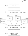
본 발명의 일부 양태들에서, 확산기를 제조하는 방법이 제공된다. 방법은 제1 구조화된 표면을 갖는 제1 미세복제 공구를 제공하는 단계, 서로 반대편에 있는 제1 및 제2 주 표면들을 갖는 기재를 제공하는 단계, 제1 미세복제 공구를 사용하여 기재의 제1 주 표면을 구조화하는 단계, 제2 구조화된 표면을 갖는 제2 미세복제 공구를 제공하는 단계, 및 제2 미세복제 공구를 사용하여 기재의 제2 주 표면을 구조화하는 단계를 포함한다. 제1 구조화된 표면은 표면 구조체들의 실질적으로 균일한 분포를 갖는다. 제2 구조화된 표면은 표면 구조체들의 분포를 가지며, 이는 제2 구조화된 표면의 영역에서 변동되고 제2 구조화된 표면의 제2 부분에 걸쳐 실질적으로 균일하다. 제2 부분은 제2 구조화된 표면의 표면적의 90% 이상의 표면적을 갖는다. 제1 미세복제 공구를 제공하는 단계는, 금속을 제1 전기도금 공정을 사용하여 전착(electrodepositing)시킴으로써 금속의 제1층을 형성하여 제1 평균 조도(roughness)를 갖는 제1 층의 제1 주 표면을 생성하는 단계, 및 금속을 제2 전기도금 공정을 사용하여 제1 주 표면 상에 전착시킴으로써 제1 층의 제1 주 표면 상에 금속의 제2 층을 형성하여 제1 평균 조도보다 작은 제2 평균 조도를 갖는 제2 층의 제2 주 표면을 생성하는 단계를 포함한다. 제2 미세복제 공구를 제공하는 단계는 사전 형성된 공구의 표면 내로 구조체들을 절삭하기 위한 절삭 시스템을 사용하는 것을 포함한다.In some aspects of the invention, a method of manufacturing a diffuser is provided. The method comprises the steps of providing a first microreplication tool having a first structured surface, providing a substrate having first and second major surfaces opposite to each other, Structuring the major surface, providing a second microreplication tool having a second structured surface, and structuring the second major surface of the substrate using a second microreplication tool. The first structured surface has a substantially uniform distribution of surface structures. The second structured surface has a distribution of surface structures that varies in the region of the second structured surface and is substantially uniform over the second portion of the second structured surface. The second portion has a surface area of at least 90% of the surface area of the second structured surface. The step of providing a first microreplication tool comprises forming a first layer of metal by electrodepositing the metal using a first electroplating process to form a first layer of metal with a first average roughness, And forming a second layer of metal on the first major surface of the first layer by electrodepositing the metal on the first major surface using a second electroplating process to form a second less than the first average roughness, And creating a second major surface of the second layer having a second average roughness. Providing the second microreplication tool includes using a cutting system for cutting the structures into the surface of the preformed tool.
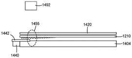
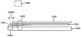
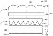
본 발명의 일부 양태들에서, 광학 필름 및 광학 필름과 실질적으로 동연적인(coextensive) 광학 확산기를 포함하는 광학 스택이 제공된다. 광학 필름은 제1 방향을 따라 선형으로 연장되는 복수의 실질적으로 평행한 상부 구조체들을 포함하는 구조화된 상부 표면; 및 제1 방향과 상이한 제2 방향을 따라 선형적으로 연장되는 실질적으로 평행한 복수의 하부 구조체들을 포함하는 구조화된 하부 표면을 포함하며, 각각의 상부 및 하부 구조체는 구조체의 기부(base)의 서로 반대편에 있는 제1 및 제2 단부들 각각으로부터 연장되어 구조체의 피크에서 만나는 서로 반대편에 있는 제1 및 제2 만곡면들을 포함한다. 광학 확산기는, 광학 필름의 구조화된 하부 표면에 대면하고, 구조화된 상부 표면을 가로질러 실질적으로 균일한 제1 광학 탁도를 갖는 구조화된 상부 표면; 및 제1 부분 및 제2 부분을 갖는 구조화된 하부 표면을 포함하며, 제1 부분은 구조화된 하부 표면의 제1 에지를 따르고, 제2 부분은 제1 부분으로부터 구조화된 하부 표면의 반대편 제2 에지까지 연장되고, 제2 부분은 제2 부분을 가로질러 실질적으로 균일한 제2 광학 탁도를 가지고, 제1 부분의 적어도 일부 영역들은 제1 광학 탁도 이상인 제3 광학 탁도를 가지며, 제2 광학 탁도는 제1 광학 탁도 미만이다.In some aspects of the invention, an optical stack is provided that includes an optical film and an optical diffuser substantially coextensive with the optical film. The optical film comprises a structured upper surface comprising a plurality of substantially parallel superstructures extending linearly along a first direction; And a structured lower surface comprising a plurality of substantially parallel lower structures extending linearly in a second direction different from the first direction, each upper and lower structure having a base And first and second curved surfaces that extend from each of the first and second ends on opposite sides and face each other at a peak of the structure. The optical diffuser comprises a structured upper surface facing the structured lower surface of the optical film and having a first optical turbidity substantially uniform across the structured upper surface; And a structured bottom surface having a first portion and a second portion, wherein the first portion follows a first edge of the structured bottom surface and the second portion extends from a first portion to a second opposite edge of the structured bottom surface, And the second portion has a second optical turbidity substantially uniform across the second portion, at least some regions of the first portion having a third optical turbidity above the first optical turbidity, and the second optical turbidity Is less than the first optical turbidity.
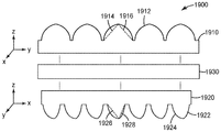
본 발명의 일부 양태들에서, 광원, 광원에 근접한 입력 표면 및 출력 표면을 갖는 도광체, 도광체 상에 배치되는 광학 확산기, 및 광학 확산기 상에 배치되는 광학 필름을 포함하는 백라이트가 제공된다. 광학 확산기는 구조화된 상부 표면을 가로질러 실질적으로 균일한 제1 광학 탁도를 갖는 구조화된 상부 표면; 및 도광체의 출력 표면에 대면하는 구조화된 하부 표면을 포함하며, 구조화된 하부 표면은 도광체의 입력 표면에 근접한 구조화된 하부 표면의 제1 에지를 따른 제1 부분, 및 제1 부분으로부터 구조화된 하부 표면의 반대편 제2 에지까지 연장되는 제2 부분을 가지고, 제2 부분은 제2 부분을 가로질러 실질적으로 균일한 제2 광학 탁도를 가지고, 제1 부분의 적어도 일부 영역들은 제1 광학 탁도 이상의 제3 광학 탁도를 가지며, 제2 광학 탁도는 제1 광학 탁도와 상이하다. 광학 필름은 광학 확산기의 구조화된 상부 표면에 대면하는 복수의 실질적으로 선형의 평행한 제1 구조체들을 포함하는 제1 구조화된 표면; 및 광학 확산기의 구조화된 상부 표면으로부터 멀어지는 방향으로 대면하는 복수의 실질적으로 선형의 평행한 제2 구조체들을 포함하는 제2 구조화된 표면을 포함하며, 각각의 제1 및 제2 구조체는 서로 반대편에 있는 만곡된 제1 및 제2 면들을 포함하며, 만곡된 제1 및 제2 면들은 상이한 곡률의 축을 갖는다.In some aspects of the invention, a backlight is provided that includes a light source, a light guide having an input surface proximate to the light source and an output surface, an optical diffuser disposed on the light guide, and an optical film disposed on the optical diffuser. The optical diffuser comprises a structured top surface having a first optical turbidity substantially uniform across the structured top surface; And a structured bottom surface facing the output surface of the light guide body, wherein the structured bottom surface includes a first portion along a first edge of the structured bottom surface proximate the input surface of the light guide, The second portion having a second optical turbidity substantially uniform across the second portion and at least some regions of the first portion having a first optical turbidity greater than the first optical turbidity, Has a third optical turbidity, and the second optical turbidity is different from the first optical turbidity. The optical film comprises a first structured surface comprising a plurality of substantially linear parallel first structures facing the structured upper surface of the optical diffuser; And a second structured surface comprising a plurality of substantially linear parallel second structures facing away from the structured upper surface of the optical diffuser, each first and second structures being opposite Wherein the curved first and second surfaces have different curvature axes.
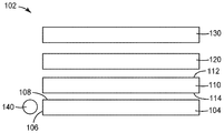
도 1a는 확산기를 포함하는 디스플레이의 개략적 측면도이다.
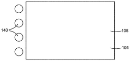
도 1b는 도 1a의 디스플레이의 도광체 및 광원들의 개략적 상부도이다.
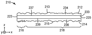
도 2a는 확산기의 측면도이다.
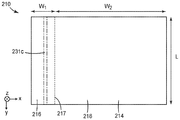
도 2b 및 도 2c는 도 2a의 확산기의 개략적 저면도들이다.
도 3a 내지 도 3d는 위치의 함수로서의 탁도를 나타내는 그래프들이다.
도 4는 구조화된 표면의 일부분의 개략적 평면도이다.
도 5는 구조화된 표면의 일부분의 개략적 측면도 또는 단면도이다.
도 6은 구조화된 표면의 일부분의 개략적 평면도이다.
도 7은 파워 스펙트럼 밀도 대 공간 주파수의 그래프이다.
도 8은 구조화된 층의 일부분의 개략적 측면도 또는 단면도이다.
도 9는 구조화된 표면을 제조하기 위해 사용되는 단계들을 도시하는 개략적 흐름도이다.
도 10은 절삭 공구 시스템의 개략적 측면도 또는 단면도이다.
도 11은 구조화된 층의 일부분의 개략적 측면도이다.
도 12a 내지 도 12c는 탁도 측정 기술의 개략도들이다.
도 13은 거리의 함수로서의 탁도의 그래프이다.
도 14a 및 도 14b는 열점(hot spot) 측정 기술의 개략도들이다.
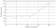
도 15는 거리의 함수로서의 열점 콘트라스트의 그래프이다.
도 16은 보완적 누적 경사도 분포의 그래프이다.
도 17은 광학 필름의 분할 전방측 입면 단면도이다.
도 18은 광학 필름 및 확산기를 포함하는 백라이트의 분할 전방측 입면 단면도이다.
도 19는 다른 광학 필름의 분할 전방측 입면 단면도이다.1A is a schematic side view of a display comprising a diffuser.
1B is a schematic top view of a light guide and light sources of the display of FIG.
2A is a side view of the diffuser.
Figures 2b and 2c are schematic bottom views of the diffuser of Figure 2a.
Figures 3a-3d are graphs showing the turbidity as a function of position.
Figure 4 is a schematic plan view of a portion of the structured surface.
Figure 5 is a schematic side view or cross-sectional view of a portion of the structured surface.
Figure 6 is a schematic plan view of a portion of the structured surface.
Figure 7 is a graph of power spectral density versus spatial frequency.
Figure 8 is a schematic side view or cross-sectional view of a portion of the structured layer.
Figure 9 is a schematic flow diagram illustrating the steps used to make a structured surface.
Figure 10 is a schematic side view or cross-sectional view of a cutting tool system.
Figure 11 is a schematic side view of a portion of the structured layer.
Figures 12A-12C are schematic diagrams of turbidity measurement techniques.
13 is a graph of turbidity as a function of distance.
14A and 14B are schematic diagrams of a hot spot measurement technique.
15 is a graph of hot spot contrast as a function of distance.
16 is a graph of the complementary cumulative gradient distribution.
Fig. 17 is a fragmentary front side elevational sectional view of the optical film. Fig.
18 is a fragmentary front side elevational sectional view of a backlight including an optical film and a diffuser.
19 is a fragmentary front side elevation sectional view of another optical film.
하기 설명에서, 본 발명의 일부를 형성하고 예시로서 도시된 첨부 도면을 참조한다. 도면은 반드시 축척대로 그려진 것은 아니다. 다른 실시예들이 고려되고, 이는 본 발명의 범주 또는 사상으로부터 벗어남이 없이 이루어질 수 있다는 것이 이해된다. 따라서, 하기의 상세한 설명은 제한적 의미로 해석되지 않아야 한다.In the following description, reference is made to the accompanying drawings which form a part hereof, and which are illustrated by way of illustration. The drawings are not necessarily drawn to scale. It is to be understood that other embodiments are contemplated and may be made without departing from the scope or spirit of the invention. Accordingly, the following detailed description should not be construed in a limiting sense.
액정 디스플레이들(LCDs)와 같은 투과성 디스플레이들에 사용되는 백라이트들은 종종 도광체, 및 도광체의 입력 에지 내로 광을 주입하도록 배치되는 복수의 발광 다이오드들(LEDs)을 포함할 수 있는 광원을 포함한다. 전형적으로 도광체는 광이 도광체의 출력 표면을 통해 추출되도록 배치되는 추출 특징부들을 포함한다. 확산기는 디스플레이로부터의 광 출력의 균일성을 개선하기 위해 도광체와 디스플레이 패널 사이에 배치될 수 있다. 그러나, 열점들(보다 낮은 세기의 영역들로 둘러싸인 상대적으로 높은 세기의 영역들)을 제거하기 위해 높은 수준의 탁도가 전형적으로 필요하고, 균일한 높은 탁도를 갖는 확산기는 디스플레이의 밝기를 바람직하지 않게 감소시킬 수 있다. 이는 주입 에지 근처에서 높은 탁도, 주입 에지로부터 멀어질수록 더 낮은 탁도를 갖는 가변 탁도를 갖는 확산기를 사용함으로써 해소될 수 있다. 그러나, 이것은 가변 탁도와 연관된 바람직하지 않은 가시적 아티팩트를 초래할 수 있다.Backlights used in transmissive displays, such as liquid crystal displays (LCDs), often include a light guide and a light source that may include a plurality of light emitting diodes (LEDs) arranged to inject light into the input edge of the light guide . Typically, the light guide includes extraction features that are arranged to extract light through the output surface of the light guide. The diffuser may be disposed between the light guide and the display panel to improve the uniformity of light output from the display. However, a high level of turbidity is typically required to remove hot spots (regions of relatively high intensity surrounded by areas of lower intensity), and a diffuser with uniform high turbidity may undesirably degrade the brightness of the display . This can be overcome by using a diffuser with a high turbidity near the injection edge, and a variable turbidity with a lower turbidity away from the injection edge. However, this can result in undesirable visible artifacts associated with variable turbidity.
본 발명에 따르면, 확산기 필름의 두 개의 개별적인 확산 표면들의 효과를 가변 탁도를 나타내는 두 개의 표면 중 단지 하나의 표면에만 조합하면, 가변 탁도로 인해 발생할 수 있는 원하지 않는 광학 아티팩트 없이 높고 균일한 밝기를 제공할 수 있다는 것이 밝혀졌다. 일부 실시예들에서, 본 발명에 따른 광학 확산기는 실질적으로 균일한 탁도를 제공하는 제1 표면을 가지며, 입력 에지 부근에서 변동되고 입력 에지로부터 멀어지는 방향으로 실질적으로 균일한 탁도를 갖는 반대편 제2 표면을 갖는다. 일부 실시예들에서, 도광체의 출력 표면에 대면하는 제2 표면을 갖는 확산기 필름을 포함하는 디스플레이가 제공된다. 확산기의 제2 표면은 또한 확산기가 도광체에 바로 인접하게 배치된 경우에 광학 아티팩트가 생성되지 않도록 웨트아웃 방지(anti-wetout, AWO) 기능을 제공할 수 있다. 제2 주 표면의 구조체들이 원하는 수준의 탁도를 제공하기 위해 종래의 AWO 층들보다 크고/크거나 더 조밀하게 배열될 수 있기 때문에, 확산기의 제2 표면의 구조체들은 종래의 AWO 층들보다 더 강력한 웨트아웃 방지 기능을 제공할 수 있다.According to the present invention, combining the effects of the two individual diffusing surfaces of the diffuser film on only one of the two surfaces exhibiting variable turbidity provides a high and uniform brightness without undesirable optical artifacts that can occur due to variable turbidity It can be done. In some embodiments, an optical diffuser in accordance with the present invention has a first surface that provides a substantially uniform turbidity and has an opposite second surface having a substantially uniform turbidity that varies near the input edge and is away from the input edge Respectively. In some embodiments, a display is provided that includes a diffuser film having a second surface facing the output surface of the light guide. The second surface of the diffuser may also provide an anti-wetout (AWO) function to prevent optical artifacts from being produced when the diffuser is positioned immediately adjacent the light guide. Because the structures of the second major surface can be arranged larger / larger or denser than conventional AWO layers to provide a desired level of turbidity, the structures of the second surface of the diffuser are more powerful than conventional AWO layers Prevention function can be provided.
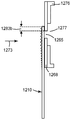
도 1a는 입력 에지(106) 및 출력 표면(108)을 갖는 도광체(104), 출력 표면(108)에서 멀어지는 방향으로 대면하는 제1 주 표면(112) 및 출력 표면(108)에 대면하는 반대편 제2 주 표면(114)을 가지고 출력 표면(108)에 인접하게 배치되는 확산기(110), 도광체(104) 반대편에 있는 확산기(110)에 인접하게 배치되는 광학 필름들(120), 확산기(110)의 반대편에 있는 광학 필름들(120)에 인접하게 배치되는 디스플레이 패널(130), 및 입력 에지(106)에 인접하게 배치되는 광원들(140)을 포함하는 디스플레이(102)의 개략적 측면도이다. 광학 필름들(120)은 예를 들어 교차 프리즘 필름과 같은 BEF(Brightness Enhancement Film)일 수 있다. 확산기(110)는 본 발명에서 설명된 확산기들 중 임의의 것일 수 있다. 도 1b는 광원들(140), 및 출력 표면(108)을 갖는 도광체(104)를 포함하는 디스플레이(102)의 일부분의 개략적 상부도이다. 도시된 실시예에서, 복수의 광원들(140)이 포함된다. 도광체(104)와 디스플레이 패널(130) 사이에 적합한 확산기(110)가 배치되지 않는다면, 열점들이 광원들(140) 각각의 부근 영역들에서 가시화될 수 있다. 에어 갭은 확산기(110)와 도광체(104)를 분리할 수 있고, 에어 갭은 확산기(110)와 광학 필름들(120)을 분리할 수 있다.1A shows a
광학 필름들(120)은 또한 확산기(110)에 인접한 방향전환 필름 또는 재순환 필름을 포함할 수 있다. 적합한 방향전환 필름들 또는 재순환 필름들은 본 출원과 동일 날짜에 출원되고 본 발명과 모순되지 않는 정도 내에서 본 발명에서 참고로 포함되는, 발명의 명칭이 "광학 필름(Optical film)"인 미국 가특허 출원 제 62/152,486호에 설명되어 있다. 이러한 광학 필름들은 본 발명의 다른 곳에서 더 설명된다.The
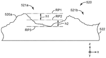
도 2a는 제1 주 표면(212), 반대편 제2 주 표면(214), 제1 및 제2 주 표면들(212 및 214) 사이에서 연장되는 제1 에지(223), 및 반대편 제2 에지(225)를 포함하는 확산기(210)의 측면도이다. 제2 주 표면(214)은 제1 에지(223)에 인접한 제1 부분(216) 및 제1 부분(216)에 인접한 제2 부분(218)을 포함한다. 제1 주 표면(212)은 실질적으로 균일한 제1 탁도를 제공하는 제1 복수의 표면 구조체들(213)을 포함한다. 제2 주 표면(214)은, 제2 주 표면(214)의 제2 부분(218)에 걸쳐 실질적으로 균일한 제2 탁도를 제공하고 제2 주 표면(214)의 제1 부분(216)에 제3 탁도를 제공하는 제2 복수의 표면 구조체들(215)을 포함한다. 제3 탁도는 제1 에지(223)에 가장 가까운 제1 부분(216)의 제1 영역(216a)(도 2b 참조)에서 실질적으로 일정하고, 제1 부분(216)의 제2 영역(216b)(도 2b 참조)에서 단조적으로 감소할 수 있다.2A shows a first
구조화된 제1 및 제2 주 표면들(212 및 214)은 일반적으로 직교하는 평면내 방향들을 따라 연장되며, 이는 도 2a 내지 도 2c에 나타낸 바와 같은 국부적 직교 x-y-z 좌표계를 정의하기 위해 사용될 수 있다. 확산기(210)의 기준 평면은 x 및 y 방향들로 연장되고, 확산기(210)의 두께는 z 방향을 따른다. x-방향은 제1 에지(223)로부터 연속 경계(217)를 향한 방향(도 2b 참조)으로서 설명될 수 있고, y-방향은 x-방향에 직교하는 평면내 방향으로서 설명될 수 있다. y-방향은 또한 에지(223)를 따른 방향으로서 설명될 수 있고, x-방향은 y-방향에 직교하는 평면내 방향으로서 설명될 수 있다.The structured first and second
도 2a에 도시된 실시예에서, 표면 구조체들(213)은 기재 층(233)의 주 표면 상에 배치되는 제1 층(234)에 형성되고, 표면 구조체들(215)은 제1 층(234)의 반대편에 있는 기재 층(233)의 주 표면 상에 배치되는 제2 층(236)에 형성된다. 기재 층(233)은 서로 반대편에 있는 주 표면들(237, 239)을 포함한다. 제1 층(234) 및 제2 층(236) 중 하나 또는 둘 모두는 경화가능한 수지가 공구(예컨대, 미세복제 공구)에 대해 주조되고 경화되는 주조 및 경화 공정에 의해 형성될 수 있다. 제1 및/또는 제2 층들(234 및 236)을 형성하기 위해 사용되는 재료의 경화는 자외선(UV) 조사, 열처리 또는 임의의 다른 공지된 방법으로 수행될 수 있다. 대안적으로, 확산기(210)는 표면 구조체들(213 및 215)이 단일체 층의 외부 주 표면들 상에 직접 형성되는 단일체 층일 수 있다. 이 경우, 구조화된 제1 및 제2 주 표면들은, 예를 들어 충분한 열과 압력으로 열가소성 기재를 엠보싱함으로써 형성될 수 있다.2A,
전형적으로, 확산기를 구성하는 층 또는 층들은 적어도 가시광선 스펙트럼의 대부분을 비추는 빛에 대해 고투과성이다. 따라서, 이러한 층 또는 층들은 전형적으로 그러한 광에 대해 낮은 흡수율을 갖는다. 캐리어 필름 또는 기재 층(233)으로 사용하기 위한 예시적인 재료들은 폴리아크릴레이트 및 폴리메타크릴레이트, 폴리카보네이트, 폴리에틸렌 테레프탈레이트, 폴리에틸렌나프탈레이트, 폴리스티렌, 시클로올레핀 중합체, 및 이들 중합체 부류들의 공중합체 또는 조합과 같은 광 투과성 중합체들을 포함한다. 패턴화된 제1 또는 제2 층(234 또는 236)으로 사용하기 위한 예시적인 재료들은 아크릴레이트 및 에폭시 수지와 같은 광 투과성 중합체들을 포함한다. 그러나, 다른 중합체 재료들뿐만 아니라 비중합체 재료들도 사용될 수 있다. 층 또는 층들은 임의의 적합한 굴절률, 예를 들어 1.4 내지 1.8 또는 1.5 내지 1.8 또는 1.5 내지 1.7의 범위를 가질 수 있지만, 이 범위를 벗어나는 값들 또한 사용될 수 있다. 굴절률은 550 nm 또는 다른 적합한 설계 파장으로 규정될 수 있거나, 가시 파장 범위에 대한 평균일 수 있다. 굴절률은 25℃로 규정될 수 있다.Typically, the layers or layers making up the diffuser are highly transmissive to light that illuminates most of the visible light spectrum. Thus, such layers or layers typically have a low absorption rate for such light. Exemplary materials for use as the carrier film or
도 2b는 제2 주 표면(214)의 제1 및 제2 부분들(216 및 218)을 도시하고, 제2 주 표면(214)의 제1 및 제2 부분들(216 및 218) 사이의 연속 경계(217)를 도시하는 확산기(210)의 개략적 저면도이다. 제1 부분(216)은 폭(W1a)을 갖는 제1 영역(216a) 및 폭(W1b)을 갖는 제2 영역(216b)을 포함한다. 제1 부분(216)은 에지(223)에 인접하고, 제2 부분(218)은 에지(223)의 반대편에 있는 제1 부분(216)에 인접하며, 제1 영역(216a)은 제1 에지(223)에 인접하고, 제2 영역(216b)은 제1 영역(216a)과 제2 부분(218) 사이에 있다. 제1 및 제2 부분들(216 및 218)은 확산기(210)의 길이(L)를 가로질러 연장될 수 있거나, 확산기의 길이(L)의 90% 이상을 가로질러 연장될 수 있다. 제1 및 제2 영역들(216a 및 216b)은 확산기(210)의 길이(L)를 가로질러 연장되거나 확산기의 길이의 90% 이상을 가로질러 연장될 수 있다. 제1 영역(216a)은 에지(223)에 바로 인접할 수 있고, 제2 영역(216b)은 제1 영역(216a)에 바로 인접할 수 있고, 제2 부분(218)은 제2 영역(216b)에 바로 인접할 수 있다. 제1 부분(216)은 폭(W1 = W1a + W1b)을 가지며, 제2 부분(218)은 폭(W2)을 갖는다. 제1 부분(216)의 제1 영역(216a)이 제2 탁도보다 높은 제3 탁도를 갖는 것은 - 제3 탁도는 제1 부분의 제2 영역(216b)에서 제1 에지(223)로부터의 거리에 따라 단조적으로 감소(즉, x에 따라 단조적으로 감소)하고, 제2 주 표면(214)의 제1 및 제2 부분들(216 및 218) 사이의 연속 경계(217)를 따라 제2 탁도와 실질적으로 동일함 -, 가변 탁도와 연관된 광학 아티팩트를 생성하지 않으면서 도광체의 입력 에지에 인접한 광원들과 연관된 열점들을 실질적으로 감소시킬 수 있다. 일부 실시예들에서, 제2 부분의 폭(W2)은 확산기의 폭(W1+W2)의 90% 이상이다. 일부 실시예들에서, W1을 W2로 나눈 값은 0.9 미만 또는 0.95 미만이다. 일부 실시예들에서, W1은 1 mm 초과이거나, 2 mm 초과이거나, 3 mm 초과이거나, 5 mm 초과이거나, 1 cm 초과이다. 일부 실시예들에서, W1a 및 W1b 중 하나 또는 둘 모두는 0.5 mm 초과 또는 1 mm 초과 또는 2 mm 초과 또는 3 mm 초과 또는 5 mm 초과 또는 1 cm 초과이다.Figure 2b illustrates the first and
제1 및 제2 주 표면들(212 및 214)의 탁도는 표면 구조체들(213 및 215)의 진폭(예컨대, 높이), 간격, 측방향 치수(예컨대, 직경) 및/또는 경사도의 기본적 분포에 관하여 설명될 수 있다. 이러한 분포들은, 분포들이 변동되는 길이 스케일에 비해 작지만, 표면 구조체들(213 및 215)의 크기에 비해 큰 영역들에서 결정될 수 있다. 예를 들어, 분포들은 제1 부분(216)의 영역(231) 및 제2 부분(218)의 영역(232)에서 결정될 수 있다. 영역(231)은 제1 영역(216a), 제2 영역(216b)에 있을 수 있거나, 제1 및 제2 영역들(216a 및 216b)에 걸칠 수 있다. 영역(231) 또는 영역(232)은 영역(231) 내의 구조체들의 평균 등가 원 직경(ECDavg)(본 발명의 다른 곳에서 더 설명됨)보다 1배, 2배, 3배, 4배 또는 5배 더 큰 직경을 갖는 원형 영역일 수 있다. 대안적으로, 영역(231 또는 232)은 예를 들어, 100 마이크로미터 또는 1 mm 또는 2 mm 또는 3 mm 또는 5 mm의 고정된 직경을 갖는 원형 영역일 수 있다. 영역(231) 또는 영역(232)과 같은 표면의 영역의 탁도 또는 투명도는 본 발명의 다른 곳에서 더 설명되는 바와 같이 탁도 측정기를 사용하여 결정될 수 있다. 일부 실시예들에서, 표면 구조체들(215)의 진폭, 간격 또는 경사도의 분포들 중 적어도 하나는 제1 부분(216)의 제2 영역(216b)에서 영역(231)의 위치(예컨대, x-위치)에 따라 변동된다. 일부 실시예들에서, 표면 구조체들(215)의 진폭, 간격 또는 경사도의 분포들 중 적어도 하나는 제1 부분(216)의 제1 영역(216a)의 영역(231)의 y-위치에 따라 변동된다. 일부 실시예들에서, 표면 구조체들(215)의 진폭, 간격 및 경사도의 분포들 각각은 제2 부분(218)의 영역(232)의 위치에 따라 변하지 않는다. 유사하게, 일부 실시예들에서, 표면 구조체들(213)의 진폭, 간격 및 경사도의 분포들 각각은 제1 주 표면(212) 상의 위치에 따라 변하지 않는다. 일부 실시예들에서, 표면 구조체들(215)의 진폭, 간격 및 경사도의 분포들 각각은 제1 부분(216)의 제1 영역(216a)의 영역(231)의 x-위치에 따라 변하지 않는다. 일부 실시예들에서, 표면 구조체들(215)의 진폭, 간격 및 경사도의 분포들은 y-좌표에 따라 변하지 않는다. 이러한 실시예들에서, 탁도는 y-좌표로 연장되는 영역에서 결정될 수 있다. 이것은 도 2c에 도시되어 있으며, 여기서 영역(231c)은 예를 들어, 1mm, 2 mm 또는 3mm의 폭을 갖는 스트립일 수 있다.The turbidity of the first and second
일부 실시예들에서, 경사도의 분포는 본 발명의 다른 곳에서 더 설명되는 바와 같이 표면각 분포들에 의해 특성화가 가능하다. 표면각 분포들은 두 개의 직교 방향(예컨대, x 및 y 방향) 각각에서 반치반폭(HWHM)에 의해 특성화가 가능할 수 있다. 일부 실시예들에서, 제2 주 표면(214)의 제1 부분(216)(예컨대, 영역(231 또는 231c)) 또는 제2 주 표면(214)의 제2 부분(218)(예컨대, 영역(232))에서 적어도 하나의 영역은 제1 방향(예컨대, x-방향)에서 제1 HWHM을 갖는 제1 표면각 분포 및 제1 방향과 상이한 제2 방향(예컨대, y-방향)에서 제2 HWHM을 갖는 제2 표면각 분포를 갖는다. 일부 실시예들에서, 제1 HWHM은 제2 HWHM과 상이하다. 일부 실시예들에서, 제2 주 표면(214)의 임의의 영역에서의 제1 HWHM은 그 영역에서의 제2 HWHM과 상이하다. 제1 및 제2 HWHM 각각은 예를 들어, 약 15도 미만 또는 약 10도 미만 또는 약 6도 미만일 수 있으며, 약 1도 내지 약 6도 또는 약 10도 또는 약 15도의 범위 내에 있을 수 있다. 제1 및 제2 HWHM는 예를 들어, 적어도 1도 또는 적어도 2도 만큼 상이할 수 있다.In some embodiments, the distribution of gradient is characterizable by surface angular distributions as further described elsewhere in the present invention. The surface angular distributions may be characterized by a half-width half-width (HWHM) in each of two orthogonal directions (e.g., x and y directions). In some embodiments, the first portion 216 (e.g.,
일부 실시예들에서, 제2 부분(218)은 제2 주 표면(214)의 표면적의 90% 이상 또는 95% 이상 또는 99% 이상의 표면적을 갖는다. 일부 실시예들에서, 제2 부분(218)은 제2 에지(225)까지 연장되지 않는다. 대신에, 제2 가변 탁도를 포함하는 제3 부분이 제2 에지(225)에 인접하게 있을 수 있다. 제3 부분의 제2 가변 탁도는 제1 부분(216)의 가변 탁도와 유사할 수 있다. 이러한 유형의 확산기는 반대편 측면들로부터 에지 조명되는(edge-lit) 백라이트들에 유용할 수 있다. 유사하게, 확산기는 제1 및 제2 에지들(223 및 225) 사이에서 연장되는 제3 및 제4 에지들을 가질 수 있고, 제3 및/또는 제4 에지들에 각각 인접하는 제4 및/또는 제5 부분들이 있을 수 있으며, 여기서 탁도는 변동될 수 있다.In some embodiments, the
도 11은 광산란 입자들(1166)을 포함하고, 피크(1172) 및 밸리(1174)를 포함하는 구조화된 표면(1171)을 갖는 구조화된 층(1140)의 단면도이다. 광선(1175)은 광선(1175)이 구조화된 표면(1171)을 통해 출사됨에 따라 굴절로 인해 변경되는 방향을 갖는다. 구조화된 표면(1171)의 기하학적 구조는 점대점(point to point)으로 변동되기 때문에, 구조화된 표면(1171)을 통해 출사되는 광의 방향의 전환은 점대점으로 변동된다. 방향의 이러한 가변적 전환은 층(1140)의 탁도에 표면 기여를 생성한다. 입자들(1166)도 층(1140)의 탁도에 기여한다. 예를 들어, 광선(1178)은 입자들(1166) 중 하나 이상에 의해 산란되어 탁도에 기여한다. 피크(1172) 아래에는 밸리(1174) 아래보다 더 많은 입자들(1166)이 있기 때문에, 피크(1172)를 통과하는 광은 밸리(1174)를 통과하는 광보다 더 많이 산란되는 경향이 있다. 따라서 구조화된 층의 표면 구조체들은 구조화된 표면과의 공기 계면에서의 굴절을 통해 탁도에 기여를 생성하고, 구조체들 내에 포함되는 입자들로 인한 산란을 생성하는 것 둘 모두에 의해 탁도를 제공할 수 있다.11 is a cross-sectional view of a
구조화된 표면을 갖는 확산기의 층에 의해 제공되는 탁도 또는 투명도는, 본 발명의 다른 곳에서 설명되는 바와 같이, 저탁도 기재(예컨대, 1% 미만의 탁도, 또는 0.5% 미만의 탁도) 상에 층을 재현하고, 탁도 측정기를 사용하여 재현된 층 및 기재를 통한 탁도 또는 투명도를 측정함으로써 결정될 수 있다. 예를 들어, 광학적으로 투명한 기재 상에 재현되는 제1 층(234) 또는 제2 층(236)을 갖는 샘플이 제조될 수 있고, 샘플을 통한 탁도 또는 투명도가 측정될 수 있다. 대안적으로, 구조화된 표면을 갖는 확산기의 층에 의해 제공되는 탁도 또는 투명도는 표면의 토포그래피를 측정하고(예를 들어, CSLM(confocal scanning laser microscopy) 또는 AFM(atomic force microscopy)을 사용함), 층과 그 층에 포함될 수 있는 임의의 광 산란 입자들의 굴절률을 측정하며, 탁도 또는 투명도에 대한 표면 구조체들의 기여도를 계산하기 위한 종래의 광선 추적 기술들을 사용함으로써 결정될 수 있다.The turbidity or transparency provided by the layer of the diffuser having the structured surface can be determined by measuring the turbidity or transparency of the layer (s) on a low turbidity substrate (e.g., less than 1% turbidity, or less than 0.5% turbidity), as described elsewhere herein And measuring the turbidity or transparency through the reproduced layer and substrate using a turbidity meter. For example, a sample having a
일부 실시예들에서, 확산기는 광산란 입자들 또는 비드(bead)들이 없거나 실질적으로 없을 수 있다. 이러한 실시예들에서, 주어진 표면에 의해 제공되는 탁도는 반대편 표면의 재료의 굴절률과 일치하는 굴절률을 갖는 재료로 반대편 표면을 코팅함으로써 측정될 수 있다. 이어서, 주어진 표면이 탁도 측정기의 광원에 대면하는 샘플을 통해 측정되는 전체 탁도가 주어진 표면에 의해 제공되는 탁도가 된다. 주어진 표면의 투명도는 또한 이러한 굴절률 매칭 기법을 사용하여 결정될 수도 있다.In some embodiments, the diffuser may be free or substantially free of light scattering particles or beads. In these embodiments, the turbidity provided by a given surface can be measured by coating the opposite surface with a material having a refractive index that matches the refractive index of the material of the opposite surface. Then, the total turbidity measured over the sample the given surface confronts the light source of the turbidity meter is the turbidity provided by the given surface. The transparency of a given surface may also be determined using such an index matching technique.
탁도, 또는 광학 탁도는 ASTM D1003-13 "투명 플라스틱의 탁도 및 광 투과율에 대한 표준 시험 방법(Standard Test Method for Haze and Luminous Transmittance of Transparent Plastics)"에 설명된 바와 같이 측정될 수 있다. 탁도는 ASTM D1003-13 표준에 언급된 비와이케이-가드너 인크.(BYK-Gardner Inc.)(미국 메릴랜드주 실버 스프링스 소재)로부터 입수가능한 헤이즈-가드 플러스(HAZE-GARD PLUS) 측정기를 사용하여 결정될 수 있다. 탁도와 관련한 것이 투명도, 또는 광학 투명도이며, 이 또한 헤이즈-가드 플러스 탁도 측정기를 사용하여 ASTM D1003-13 표준에 따라 측정될 수 있다.Turbidity, or optical turbidity may be measured as described in ASTM D1003-13 "Standard Test Method for Haze and Luminous Transmittance of Transparent Plastics ". The turbidity can be determined using a HAZE-GARD PLUS meter available from BYK-Gardner Inc. (Silver Springs, MD) mentioned in the ASTM D1003-13 standard. have. Relative to turbidity is transparency or optical transparency, which can also be measured in accordance with ASTM D1003-13 standard using a haze-guard plus turbidity meter.
ASTM D1003-13 표준에 규정되는 바와 같이, 헤이즈-가드 플러스 탁도 측정기는 시준된 광원과 샘플에 의해 산란되는 광원으로부터의 빛을 측정하기 위해 사용되는 적분구(integrating sphere) 사이의 어퍼처를 포함한다. 구조화된 층의 영역에서의 탁도 또는 투명도는 헤이즈-가드 플러스 탁도 측정기를 사용하여 측정될 수 있으며, 측정될 영역의 형상의 절단부(cutout)를 갖는 커버 시트가 어퍼처 위에 배치되고, 절단 영역의 중심이 어퍼처의 중심과 정렬된다. 커버 시트가 영역 외부의 영역으로부터의 광이 적분구로 입사되는 것을 차단함으로써 절단 영역을 커버하는 샘플의 영역만의 탁도 또는 투명도가 결정된다. 예를 들어, 2 mm 슬릿을 제외한 모든 곳에서 빛을 차단하는 커버 시트가 어퍼처 위에 배치될 수 있고, 이어서 어퍼처에 인접하게 배치된 샘플의 탁도를 결정하기 위해 탁도 측정기가 사용될 수 있다. 이어서, 생성된 탁도 판독값(reading)은 2 mm 슬릿 앞의 샘플 영역의 탁도가 된다. 2 mm 슬릿은 예를 들어 y-방향으로 균일한 샘플들의 탁도를 측정하는 데 유용하다. 다른 절단부 형상들도 사용될 수 있다. 예를 들어, 2 mm의 직경을 갖는 원형 절단부가 사용될 수 있거나 또는 영역(231, 232 또는 231c)에 대해 본 발명의 다른 곳에서 설명되는 기하학적 구조들 중 임의의 것에 대응되는 영역을 갖는 절단부가 사용될 수 있다. 구조화된 표면을 갖는 층의 탁도는 구조화된 표면을 시준된 광원에 대면하게 하여 결정될 수 있다. 확산기가 실질적으로 균일한 탁도를 제공하는 제1 표면 및 전체 제2 표면에 걸쳐 균일하지 않은 탁도를 제공하는 제2 표면을 갖는 경우, 제1 구조화된 표면이 광원에 대면하거나, 높은 탁도를 제공하는 표면이 광원에 대면하게 하여 확산기의 전체 탁도가 결정될 수 있다.As specified in the ASTM D1003-13 standard, the haze-guard plus turbidity meter includes an aperture between the collimated light source and an integrating sphere used to measure light from a light source that is scattered by the sample . The turbidity or transparency in the region of the structured layer can be measured using a haze-guard plus turbidity meter, and a cover sheet having a cutout of the shape of the area to be measured is placed on the aperture, Aligned with the center of this aperture. The turbidity or transparency of only the area of the sample covering the cut region is determined by blocking the light from the area outside the area of the cover sheet from entering the integrating sphere. For example, a cover sheet may be placed over the aperture to block light anywhere but a 2 mm slit, and then a turbidity meter may be used to determine the turbidity of the sample placed adjacent to the aperture. The turbidity readings produced are then the turbidity of the sample area before the 2 mm slit. The 2 mm slit is useful, for example, to measure the turbidity of uniform samples in the y-direction. Other cut shapes may also be used. For example, a circular cut having a diameter of 2 mm could be used, or a cut having a region corresponding to any of the geometries described elsewhere herein for the
디스플레이에 사용되는 경우에, 확산기(210)가 도광체에 근접하게 배치되며, 제2 주 표면(214)이 도광체의 출력 주 표면에 대면하고 제1 에지(223)가 도광체의 입력 에지에 인접할 수 있다. 제1 주 표면(212)과 연관된 실질적으로 균일한 탁도인 제1 탁도는 제2 주 표면(214)의 제2 부분(218)과 연관된 실질적으로 균일한 탁도인 제2 탁도를 초과할 수 있다. 제1 탁도는 제2 탁도보다 적어도 약 2%, 적어도 약 5%, 적어도 약 10% 또는 적어도 약 15% 또는 적어도 약 20%만큼 초과일 수 있다. 예를 들어, 제1 탁도가 50%이고 제2 탁도가 10%인 경우, 제1 탁도는 제2 탁도보다 40%만큼 초과이다. 일부 실시예들에서, 제2 주 표면(214)의 제1 부분(216)과 연관된 제3 탁도의 최대 값은 제1 탁도보다 크다. 예를 들어, 제3 탁도는 제1 탁도보다 적어도 약 2%, 적어도 약 5%, 적어도 약 10% 또는 적어도 약 15% 또는 적어도 약 20%만큼 초과일 수 있다.The
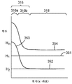
도 3은 본 발명의 확산기의 탁도 분포를 도시한다. 확산기의 제1 주 표면은 실질적으로 균일하고 값(H1)을 갖는 제1 탁도(351)를 제공한다. 확산기의 제2 주 표면은 제2 부분(318)(제2 부분(218)에 대응함)에 제2 탁도(352)를, 그리고 제1 부분(316)(제1 부분(216)에 대응함)에 제3 탁도(353)를 제공한다. 제1 부분(316)의 제1 영역(316a)(제1 영역(216a)에 대응함)의 제3 탁도(353)는 제2 부분(318)의 제2 탁도(352)보다 크며, 제1 주 표면에 의해 제공되는 제1 탁도(351)보다 크다. 제2 영역(316b)에서의 제3 탁도(353)는 제1 에지로부터 제1 및 제2 부분들(316 및 318) 사이의 경계를 향한 방향을 따른 거리에 따라 단조적으로 감소한다(즉, x-좌표를 따라 단조적으로 감소함). 확산기는 구조화된 제1 및 제2 주 표면들(예컨대, 제1 및 제2 주 표면들(212 및 214))의 조합에 의해 제공되는 전체 탁도(354)를 갖는다. 전체 탁도(354)는 제3 탁도(353)로부터의 기여로 인해 위치에 따라 변동될 수 있다. 일부 실시예들에서, 기재(예컨대, 기재(233)) 내에 포함되는 광산란 입자들은 전체 탁도에 추가적인 기여를 제공한다. 전체 탁도는 제1 및 제2 표면들로부터의 기여들의 단순한 선형 합이 아닐 수 있다. 제2 부분(318)의 제2 주 표면의 제2 탁도(352)는 약 H2이고, 제1 부분(316)의 제2 주 표면의 제3 탁도(353)는 Hm의 최대 값을 갖는다. 도시된 실시예에서,Figure 3 shows the turbidity distribution of the diffuser of the present invention. The first major surface of the diffuser provides a
Hm > H1 > H2.H m > H 1 > H 2 .
탁도 값들의 이러한 배열은, 가변 탁도로 인한 원하지 않는 광학 아티팩트를 추가하지 않고 열점의 가시성을 감소시키면서, 높은 밝기 출력을 제공하는 데에 특히 유리한 것으로 밝혀졌다. 일부 실시예들에서, Hm - H1은 약 2% 이상 또는 약 5% 이상 또는 약 10% 이상이고/이거나, H1 - H2는 약 2% 이상 또는 약 5% 이상 또는 약 10% 이상이다. 일부 실시예들에서, Hm은 50% 이상 또는 60% 이상 또는 70% 이상이다. 일부 실시예들에서, H1은 약 10% 또는 약 15% 내지 약 50% 또는 약 60% 또는 약 70% 또는 약 80% 또는 약 90% 또는 약 95% 또는 약 100%의 범위 내에 있다. 일부 실시예들에서, H1은 약 50% 초과 또는 약 60% 초과 또는 약 70% 초과이다. 일부 실시예들에서, 제1 주 표면은 약 1% 또는 약 2% 또는 약 3% 내지 약 30% 또는 약 40%의 범위 내의 광학 투명도를 갖는다. 일부 실시예들에서, H2는 약 0.5% 또는 약 1% 또는 약 2% 내지 약 15% 또는 약 18% 또는 약 20% 또는 약 40% 또는 약 50% 또는 약 70% 또는 약 90% 또는 약 95%의 범위 내에 있다. 일부 실시예들에서, 제2 주 표면은 제2 주 표면의 모든 부분들 및 영역들에서 약 85% 이하의 광학 투명도를 갖는다. 일부 실시예들에서, 제2 주 표면의 제1 부분 또는 제2 부분은 1% 초과 또는 2% 초과 또는 3% 초과이고, 50% 미만 또는 60% 미만 또는 90% 미만 또는 100% 미만일 수 있는 광학 투명도를 가질 수 있다. 일부 실시예들에서, 제2 주 표면의 제2 부분은 약 5% 내지 약 100% 범위 내의 광학 투명도를 가질 수 있고, 제1 주 표면은 약 3% 내지 약 20% 범위 내의 광학 투명도를 가질 수 있다.This arrangement of turbidity values has been found to be particularly advantageous for providing high brightness output, while reducing the visibility of the hot spots without adding undesired optical artifacts due to variable turbidity. In some embodiments, H m -H 1 is greater than or equal to about 2% or greater than or equal to about 5% or greater than or equal to about 10% and / or H 1 -H 2 is greater than or equal to about 2% or greater than or equal to about 5% to be. In some embodiments, H m is greater than 50% or greater than 60% or greater than 70%. In some embodiments, H 1 is in the range of about 10% or about 15% to about 50% or about 60% or about 70% or about 80% or about 90% or about 95% or about 100%. In some embodiments, H 1 is greater than about 50% or greater than about 60% or greater than about 70%. In some embodiments, the first major surface has an optical clarity in the range of about 1% or about 2%, or about 3% to about 30% or about 40%. In some embodiments, H 2 is about 0.5% or about 1%, or about 2% to about 15%, or about 18%, or about 20%, or about 40%, or about 50%, or about 70% 95%. In some embodiments, the second major surface has an optical transparency of about 85% or less in all portions and regions of the second major surface. In some embodiments, the first or second portion of the second major surface has an optical density that can be greater than 1% or greater than 2% or greater than 3%, less than 50%, or less than 60%, or less than 90%, or less than 100% It can have transparency. In some embodiments, the second portion of the second major surface may have optical clarity in the range of about 5% to about 100%, and the first major surface may have optical clarity in the range of about 3% to about 20% have.
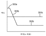
대안적인 탁도 분포가 도 3b에 도시된다. 제1 주 표면은 실질적으로 일정한 제1 탁도(351b)를 제공하고, 제2 주 표면의 제2 부분은 실질적으로 일정한 제2 탁도(352b)를 제공하며, 제2 주 표면의 제1 부분은 제1 부분의 제1 영역에서 실질적으로 일정한 값(353a)을 갖고 제2 주 표면의 제2 부분의 제2 영역에서 단조적으로 감소하는 값(353b)을 갖는 제3 탁도를 제공한다.An alternative turbidity distribution is shown in Figure 3b. The first major surface provides a substantially constant
본 발명에 설명된 실시예들 중 임의의 실시예에서, 제2 주 표면의 제1 부분의 제2 영역에서의 제3 탁도는 도 3b에 도시된 바와 같이, 단조적으로 선형적으로 감소할 수 있거나, 또는 단조적으로 감소하는 탁도는 x-좌표의 다항식 함수 또는 조각적(piece-wise) 다항식 함수에 의해 표현될 수 있다. 다항식 함수는 큐빅 스플라인(cubic spline)일 수 있는 스플라인일 수 있다. 큐빅 스플라인과 같은 비선형 함수는, 단순한 선형 감소에 비해 감소된 광학 아티팩트를 생성하는 것으로 밝혀졌다.In any of the embodiments described in the present invention, the third turbidity in the second region of the first portion of the second major surface can be monotonically and linearly reducible, as shown in Figure 3b. Or monotonically decreasing turbidity may be represented by a polynomial function of a x-coordinate or a piece-wise polynomial function. The polynomial function can be a spline, which can be a cubic spline. Nonlinear functions such as cubic splines have been found to produce reduced optical artifacts compared to simple linear reductions.
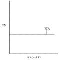
제1 부분(216)의 탁도는 y-좌표에 의존하거나 의존하지 않을 수 있다. 도 3c 및 도 3d는 제1 부분(216)에서 고정된 x-좌표에 대한 y-좌표의 함수로서의 제3 탁도(353c 및 353d)를 각각 도시한다. X-좌표는 제1 또는 제2 영역들(216a 또는 216b) 중 어느 하나일 수 있다, 제3 탁도(353d)가 y-좌표에 따라 주기적으로 변동되는 한편 제3 탁도(353c)는 y-좌표로부터 독립적이다. 개선된 균일성을 제공하기 위해, 제3 탁도는 예를 들어, 에지 조명 디스플레이에 포함되는 LED들에 상응하여 주기적으로 변조될 수 있다. 가장 높은 탁도 영역들은 열점들이 발생할 수 있는 영역들에 있을 수 있다. 열점 영역들은 백라이트에 사용되는 추출기들의 구성들 때문에 LED들의 위치로부터 오프셋될 수 있다. 일부 경우들에서, 추출기들이 LED들 사이의 위치들에 열점들을 생성할 수 있기 때문에 LED들 사이에 가장 높은 탁도 영역들을 배치하는 것이 바람직할 수 있다.The turbidity of the
일부 실시예들에서, 탁도의 급격한 변화로 인해 생성된 광학 아티팩트가 생성되지 않도록, 확산기의 전체 탁도는 확산기에 걸쳐 매끄럽게 변동된다. 그러나, 탁도는 제2 주 표면(214)의 제1 부분(216)의 제2 영역(216b)의 폭(W1b)의 길이 스케일 상에서 현저하게 변화하는 것이 바람직할 수 있다. 비록 이러한 길이 스케일은 작지만(예컨대, 확산기의 전체 폭(W1 + W2)의 10% 미만), 확산기의 제1 주 표면이 제2 주 표면의 가변 탁도에 의해 생성될 수 있는 임의의 아티팩트를 마스킹할 수 있는 균일한 탁도를 갖는다면, 실질적으로 바람직하지 않은 광학 아티팩트 없이 폭 W1b의 스케일 상에서 탁도가 변동될 수 있다. 급격한 가변 탁도에 기인하는 광학 아티팩트를 기피하는 것과 동시에 폭(W1b)의 길이 스케일 상에서 탁도를 현저하게 변경하기 위해서는, 본 발명의 다른 곳에서 더 설명되는 바와 같이, 광의 파장 초과, 또는 픽셀 크기 초과, 또는 평균 등가 원 직경(ECDavg) 초과의 길이 스케일 상에서 탁도를 점진적으로 변경하는 것이 바람직할 수 있다. 일부 실시예들에서, 이는 충분히 큰 W1b를 선택함으로써 달성된다. 예를 들어, W1b는 약 0.5 mm 초과 또는 약 1 mm 초과 또는 약 2 mm 초과 또는 약 3 mm 초과 또는 약 5 mm 초과일 수 있다.In some embodiments, the total turbidity of the diffuser varies smoothly across the diffuser, so that optical artifacts produced due to abrupt changes in turbidity are not generated. However, turbidity may desirably vary significantly on the length scale of the width W 1b of the
탁도는 탁도의 급격한 전환이 없는 경우 연속적으로 또는 실질적으로 연속적으로 변동된다고 할 수 있다. 예를 들어, 제1 부분(216)의 제3 탁도는 제2 주 표면 상의 위치에 따른 제3 탁도의 급격한 변화가 없다면, 실질적으로 연속적으로 가변된다고 할 수 있다. 제1 및 제2 위치들이 서로 0.1 mm 내에 있는 경우에 제1 위치에서의 제1 탁도값이 제2 위치에서의 제2 탁도값과 10% 이상 상이하다면 탁도가 격하게 변동된다고 할 수 있다. 일부 실시예들에서, 제3 탁도는 제1 부분(216)에서 임의의 급격한 변화를 나타내지 않는다. 일부 실시예들에서, 0.1 mm 이하로 분리되는, 또는 0.5 mm 이하로 분리되는 제1 및 제2 위치들의 각각의 쌍에 대한 제1 위치에서의 제3 탁도와 제2 위치에서의 제3 탁도 사이의 크기 차이는 20% 이하 또는 10% 이하이다.Turbidity can be said to vary continuously or substantially continuously in the absence of rapid turbidity change. For example, the third turbidity of the
원하는 탁도 분포를 생성하는 구조화된 표면의 임의의 유형이 사용될 수 있다. 예들은 프리즘이 무작위로 변형되거나 불균일하게 이격될 수 있는 프리즘들 또는 프리즘형 구조체들; 불균일하게 이격될 수 있고, 하나의 방향으로 어느 정도 연장될 수 있는, 무작위 또는 불규칙한 구조체들; 및 두 개의 직교하는 평면내 방향들을 따라 크기가 제한될 수 있는 다른 무작위 또는 불규칙한 구조체들을 포함한다.Any type of structured surface that produces a desired turbidity distribution may be used. Examples include prisms or prism-like structures that the prism may be randomly deformed or unevenly spaced; Random or irregular structures that can be unequally spaced and extend to some extent in one direction; And other random or irregular structures that may be limited in size along two orthogonal in-plane directions.
구조화된 제2 주 표면은, 예를 들어, 기재(233)의 측면(239) 상에 층(236)을 인쇄하여 제조될 수 있다. 구배를 갖는 패턴이 탁도에서 원하는 구배를 생성하도록 인쇄될 수 있다. 인쇄는 예를 들어, 오프셋 인쇄 또는 잉크젯 인쇄를 사용하여 수행될 수 있다. 투명한 수지 또는 비드 수지가 층(236)을 형성하기 위해 인쇄될 수 있다. 예를 들어, 유리 또는 중합체 비드들이 있거나 없는 UV 경화성 아크릴 수지가 사용될 수 있다. 인쇄된 패턴은 높이, 간격 및/또는 직경 또는 측방향 치수에서 구배를 갖는 작은 도트들 또는 렌즈릿(lenselet)들의 형태일 수 있다. 대안적으로, 구조화된 제2 주 표면은 높이, 간격, 측방향 치수 및/또는 경사도 분포에 구배를 갖는 패턴을 갖는 복제 공구에 대하여 주조 및 경화에 의해 제조될 수 있다.The structured second major surface may be fabricated, for example, by printing
제1 주 표면(212)이 국제 특허 출원 공개 WO 2014/081693호(팜(Pham) 등)에 전반적으로 설명된 바와 같이 형성된 표면 구조체들을 갖고/갖거나 제2 주 표면(214)이 미국 특허 제8,657,472호(아론슨(Aronson) 등) 또는 제8,888,333호(야펠(Yapel) 등)에 전반적으로 설명된 바와 같이 형성된 표면 구조체들을 갖는 것이 특히 유리하다는 것이 밝혀졌지만, 일부 경우들에서 제2 주 표면의 탁도는 미국 특허 제8,657,472호(아론슨 등) 또는 제8,888,333호(야펠 등)의 표면들의 탁도들을 초과하도록 요구될 수 있다. 국제 특허 출원 공개 WO 2014/081693호(팜 등), 미국 특허 제8,657,472호(아론슨 등), 및 미국 특허 제8,888,333호(야펠 등) 각각은 이로써 이들이 본 발명과 모순되지 않는 한에 있어서 본 발명에 참고로 포함된다. 국제 특허 출원 공개 WO 2014/081693호(팜 등)에 따라 형성된 구조체들이 유용한 정도의 탁도 및 광학 투명도를 제공하는 한편, 미국 특허 제8,657,472호(아론슨 등) 또는 제8,888,333호(야펠 등)에 따라 형성되는 구조체들도 유용한 정도의 탁도 및 광학 투명도를 제공하면서도, 디스플레이의 도광체에 바로 인접하게 배치된 경우에 광학 결함들을 방지하는 웨트아웃 방지 기능을 또한 제공한다. 본 발명의 다른 곳에서 더 설명된 바와 같이, 미국 특허 제8,657,472호(아론슨 등) 또는 제8,888,333호(야펠 등)의 구조체들을 제조하기 위해 사용되는 공구는 제2 주 표면(214)의 제1 부분(216)에서 연속적 가변 탁도를 제공하도록 구성될 수 있다. 제1 및 제2 주 표면들 중 하나의 설명에 사용되는 양, 예컨대 등가 원 직경(ECD) 또는 경사도 크기 분포는 또한 다른 주 표면을 설명하는 데 사용될 수 있다.The first
제1 주 표면을 국제 특허 출원 공개 WO 2014/081693호(팜 등)에 설명된 바와 같이, 그리고 제2 주 표면을 미국 특허 제8,657,472호(아론슨 등) 또는 미국 특허 제8,888,333호(야펠 등)에 설명된 바와 같이 형성하는 경우에, 제1 주 표면은 제2 주 표면의 제2 부분보다(제2 탁도) 높은 탁도(제1 탁도)를 갖도록 요구될 수 있다. 이것은 적어도 2가지 이유 때문이다. 첫째, 제2 탁도가 증가된 경우, 원하는 전체 탁도를 생성하기 위해 제1 탁도를 낮추는 것이 요구될 수 있으며, 더 낮은 탁도 표면을 제조하기 위해 국제 특허 출원 공개 WO 2014/081693호(팜 등)의 도금 공정을 사용하기 위해 더 많은 시간과 비용을 소요할 수 있다. 둘째, 확산기는 제1 주 표면이 디스플레이의 출력 방향에 대면하게 하여 디스플레이 내에 배치되도록 구성될 수 있다. 이러한 구성에서, 높은 탁도를 갖는 구조화된 제1 주 표면은 재순환 효과를 제공함으로써, 디스플레이의 높은 축상 휘도(luminance)에 기여할 수 있다. 또한, 상대적으로 높은 제1 탁도는 제2 주 표면의 제1 부분의 가변 탁도에 의해 생성될 수 있는 임의의 아티팩트를 마스킹하게 도울 수 있다.The first major surface may be used as described in International Patent Application Publication No. WO 2014/081693 (Palm et al.), And the second major surface is disclosed in U.S. Patent No. 8,657,472 (Aronsen et al.) Or U.S. Patent No. 8,888,333 The first major surface may be required to have a higher turbidity (first turbidity) than the second portion of the second major surface (second turbidity). This is for at least two reasons. First, if the second turbidity is increased, it may be required to lower the first turbidity to produce the desired total turbidity, and to obtain a lower turbidity surface, the method of International Patent Application Publication No. WO 2014/081693 (Palm et al.) It may take more time and money to use the plating process. Second, the diffuser may be configured to be disposed within the display such that the first major surface faces the output direction of the display. In such an arrangement, the structured first major surface with high turbidity can contribute to the high axial luminance of the display by providing a recirculating effect. In addition, a relatively high first turbidity may help mask any artifacts that may be produced by the variable turbidity of the first portion of the second major surface.
구조화된 제1 또는 제2 주 표면들(212 및 214)의 토포그래피는 구조화된 제1 및 제2 주 표면들(212 및 214)에 평행하게 놓인 기준 평면(x-y 평면)에 대한 두께 방향(z-축)을 따른 편차에 관하여 표현될 수 있다. 많은 경우들에서, 구조화된 표면의 토포그래피는 별개의 개별 구조체들을 식별할 수 있도록 한다. 이러한 구조체들은 구조화된 표면 공구의 대응되는 공동들로부터 만들어지는 돌출부들, 또는 구조화된 표면 공구의 대응되는 돌출부들로부터 만들어지는 공동들의 형태일 수 있다. 구조체들은 전형적으로 두 개의 직교하는 평면내 방향을 따라 크기가 제한된다. 예를 들어, 구조화된 제1 주 표면(212) 또는 구조화된 제2 주 표면(214)을 평면도로 보는 경우에, 전형적으로 개별 구조체들은 임의의 평면내 방향을 따라 선형 방식으로 무한 연장되지 않는다. 돌출부이든 공동이든, 구조체들은 또한 일부 경우들에서 밀집 패킹될 수 있으며, 즉, 이들은 많은 또는 대부분의 인접한 구조체들의 적어도 경계 부분들이 실질적으로 만나거나 겹치도록 배열된다. 구조체들은 또한 구조화된 표면 상에 불규칙하게 또는 불균일하게 분산될 수 있다. 일부 경우들에서, 구조체들 중 일부, 대부분, 또는 실질적으로 전부(예컨대, 90% 초과 또는 95% 초과 또는 99% 초과)는 만곡될 수 있거나, 또는 둥글거나 달리 만곡된 기부 표면을 포함할 수 있다. 일부 경우들에서, 구조체들 중 적어도 일부는 피라미드 형상일 수 있거나 또는 실질적으로 평평한 패싯(facet)에 의해 달리 정의될 수 있다. 주어진 구조체의 크기는 평면도에서 등가 원 직경(ECD)에 관하여 표현될 수 있으며, 구조화된 표면의 구조체들은 예를 들어, 15 마이크로미터 미만 또는 10 마이크로미터 미만 또는 4 내지 10 마이크로미터 또는 4 내지 15 마이크로미터 범위 내의 평균 ECD를 가질 수 있다. 구조화된 표면 및 구조체들은 또한 본 발명의 다른 곳에서 논의되는 바와 같은 다른 파라미터들을 이용하여, 예컨대, 특징적인 횡방향 치수, 예컨대 ECD에 대한 깊이 또는 높이의 종횡비, 또는 평면도에서의 단위 면적 당 표면 상의 리지(ridge)의 총 길이에 의해 특성화될 수 있다. 확산기의 광학 탁도, 광학 투명도 및 다른 특성들은, 구조화된 표면들에 또는 구조화된 표면 상에, 또는 달리 확산기 내부에 임의의 비드들을 사용하지 않고서 제공될 수 있다.The topography of the structured first or second
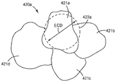
별개의 개별 구조체들이 식별될 수 있는 구조화된 표면에 대해, 구조화된 표면은 구조체들의 횡방향 또는 평면내 치수와 같은 특성 크기에 관하여 설명될 수 있다. 각각의 구조체는 예를 들어, 최대 횡방향 치수, 최소 횡방향 치수 및 평균 횡방향 치수를 갖는 것으로 특성화될 수 있다. 개별 구조체들이 두 개의 직교하는 평면내 방향들을 따라 크기가 제한되는 경우, 예컨대, 임의의 평면내 방향을 따라 선형 방식으로 무한 연장되지 않는 경우, 각각의 구조체는 등가 원 직경인 "ECD"를 갖는 것으로 특성화될 수 있다. 주어진 구조체의 ECD는 평면도에서의 면적이 구조체의 평면도에서의 면적과 동일한 원의 직경으로서 정의될 수 있다. 예를 들어, 도 4를 참조하면, 가상 구조화된 표면(420a)의 평면도가 도시되어 있다. 구조화된 표면은 돌출부들 또는 공동들일 수 있는 구별가능한 구조체들(421a, 421b, 421c, 421d)을 포함한다. 원(423a)이 구조체(421a) 상에 중첩되며, 이 평면도에서 원은 구조체(421a)의 면적과 대략 동일한 면적을 갖는다. 원(423a)의 직경(ECD)은 구조체(421a)의 등가 원 직경(ECD)이다. 구조화된 표면의 대표적인 영역의 모든 구조체들에 대한 ECD 값들의 평균을 냄으로써, 구조화된 표면 또는 그의 구조체들은 이어서 평균 등가 원 직경(ECDavg)을 갖는다고 할 수 있다.For a structured surface on which distinct individual structures can be identified, the structured surface can be described in terms of characteristic dimensions such as the transverse or in-plane dimensions of the structures. Each structure may be characterized as having, for example, a maximum transverse dimension, a minimum transverse dimension, and an average transverse dimension. When individual structures are limited in size along two orthogonal in-plane directions, for example, they do not extend infinitely in a linear fashion along any in-plane direction, each structure has an equivalent circle diameter "ECD" Can be characterized. The ECD of a given structure can be defined as the diameter of a circle whose area in the plan view is equal to the area in the plan view of the structure. For example, referring to FIG. 4, a top view of the virtual structured
예시적인 구조체의 높이가 도 5의 가상 구조화된 표면의 도면에 도시되어 있다. 도면에서, 광학 확산 필름(520)은 구조화된 주 표면(520a)과 함께 패턴화된 층(522)을 포함한다. 구조화된 표면(520a)은 식별가능한 개별 구조체들(521a, 521b)을 포함한다. 구조화된 표면은 x-y 평면을 따라 연장되거나, x-y 평면을 정의한다. x-y 평면에 평행한 세 개의 기준 평면들인 RP1, RP2 및 RP3이 도시된다. 기준 평면들(RP1, RP3)은 구조체(521a)의 (각각) 최고 및 최저 부분들에 관하여 정의될 수 있다. 기준 평면(RP2)은 0 또는 거의 0의 곡률에 대응되는 위치에 위치될 수 있으며, 즉 그 위치에서의 표면은 피크의 상부에서와 같이 내향으로 만곡되지도 않고 공동의 저부에서와 같이 외향으로 만곡되지도 않는다. 이들 기준 평면들이 주어지면, RP1과 RP2 사이의 높이(h1) 및 RP2와 RP3 사이의 높이(h2)가 정의될 수 있다. 구조체의 평균 높이는 |h1| + |h2|의 평균으로 정의될 수 있다. 일부 실시예들에서, 제1 구조화된 표면은 기준 평면(예컨대, 기준 평면(RP2))의 등가 원 직경(ECD)과 두께 방향을 따른 평균 높이로 특성화되는 밀집 패킹된 구조체들을 포함하며, 각 구조체의 종횡비는 구조체의 평균 높이를 구조체의 ECD로 나눈 것과 동일하다. 일부 실시예들에서, 구조체들의 평균 종횡비는 0.15 미만 또는 0.10 미만이다. 일부 실시예들에서, 구조체들의 평균 종횡비는 0.01 내지 0.15의 범위 내이다.The height of the exemplary structure is shown in the figure of the virtual structured surface of Fig. In the figure, the
일부 실시예들에서, 밀집 패킹된 구조체들은 리지형 특징부들을 생성하는 경향이 있지만, 리지형 특징부들은 밀집 패킹된 구조체들의 부재하에서도 발생될 수 있다. 리지가 도 6의 가상 구조화된 표면의 도면에 도시되어 있다. 도면에서, 광학 확산 필름은 구조화된 주 표면(620a)을 포함한다. 구조화된 표면(620a)은 식별가능한 개별 구조체들(621a, 621b, 621c)을 포함한다. 구조화된 표면은 x-y 평면을 따라 연장되거나, x-y 평면을 정의한다. 긴, 첨예한, 피크형 영역으로서 설명될 수 있는 리지는 구조체들(621a, 621b)의 경계들이 함께 모이는 적어도 짧은 세그먼트를 따라 형성된다. 리지 또는 세그먼트는 점들(p1, p2, p3)을 포함한다. 공지의 토포그래피에 기초하여, 이들 점들 각각에서 국부적 경사도 및 곡률은, 구배에 평행하고 리지에 수직인 방향들(축(a1, a2, a3) 참조) 뿐만 아니라, 구배에 수직이고 리지에 평행인 방향들(축(b1, b2, b3) 참조)을 따라 산출될 수 있다. 이러한 곡률들과 경사도들은, 점들이 긴, 첨예한, 피크형 영역 상에 놓인 것을 확인하기 위해 사용될 수 있다. 예를 들어, 리지 상의 점들은, 두 개의 수직 방향들을 따른 충분히 상이한 곡률(예컨대, a1, b1); 리지에 수직인 예리한 곡률(예컨대, a1); 평균 경사도 미만의 구배 방향(예컨대, 리지를 따르는 방향, b1 참조)의 경사도; 및 충분히 긴 세그먼트 길이에 의해 식별될 수 있다.In some embodiments, densely packed structures tend to produce ridge features, but ridge features can also occur under the absence of densely packed structures. The ridges are shown in the figure of the virtual structured surface of Fig. In the figure, the optical diffusion film comprises a structured
구조화된 제1 및/또는 제2 주 표면은 평면도에서 200 mm/㎟ 미만 또는 150 mm/㎟ 미만 또는 10 내지 200 mm/㎟ 또는 10 내지 150 mm/㎟ 범위 내의 단위 면적 당 총 리지 길이에 의해 특성화될 수 있다.The structured first and / or second major surfaces are characterized by a total ridge length per unit area in the plan view of less than 200 mm /
샘플의 면적 당 리지 길이는 국제 특허 출원 공개 WO 2014/081693호(팜 등)에 설명된 바와 같이 결정될 수 있다. 이러한 기법에서, 주어진 확산기 샘플에 대해, 샘플의 중심 부분으로부터 샘플의 약 1×1 cm 피스를 절단한다. 샘플 피스를 현미경 슬라이드 상에 장착하고, 특성화하기 위한 그의 구조화된 표면을 Au-Pd 스퍼터-코팅한다(sputter-coat). 공초점 주사 레이저 현미경(confocal scanning laser microscopy, CSLM)을 사용하여 구조화된 표면의 두 개의 높이 프로파일을 얻는다. 가능할 때마다, 토포그래피의 우수한 샘플링을 제공하도록 시야를 선택한다. 본 발명의 다른 곳에서 설명되는 원리들에 따라 높이 프로파일들을 분석하는데 리지 분석이 사용된다.The ridge length per area of the sample can be determined as described in International Patent Application Publication No. WO 2014/081693 (Palm et al.). In this technique, for a given diffuser sample, about 1 x 1 cm pieces of sample are cut from the center portion of the sample. The sample piece is mounted on a microscope slide and its structured surface is Au-Pd sputter-coated for characterization. Two height profiles of the structured surface are obtained using a confocal scanning laser microscope (CSLM). Whenever possible, choose a field of view to provide superior sampling of the topography. Ridge analysis is used to analyze height profiles in accordance with principles elsewhere in the present invention.
리지 분석은 2차원(2D) 높이 지도 상의 리지들의 피크들을 식별하고, 샘플 단위 면적 당 리지들의 총 길이가 계산되게 한다. 구배 방향을 따르고 구배 방향을 가로지르는 곡률이 각각의 픽셀에 대해 계산될 수 있다. 리지들을 식별하기 위해 곡률 및 경사도에 대한 임계화(thresholding)가 수행될 수 있다.Ridge analysis identifies the peaks of the ridges on a two-dimensional (2D) elevation map and allows the total length of the ridges per sample unit area to be calculated. Curvatures along the gradient direction and across the gradient direction can be calculated for each pixel. Thresholding for curvatures and gradients may be performed to identify the ridges.
다음은 리지 분석에 사용될 수 있는 리지의 정의이다.The following is a definition of the ridge that can be used for ridge analysis.
1. 곡률 정의: (a) gcurvature는 구배 방향을 따른 곡률이고; (b) tcurvature는 구배 방향을 가로지르는(수직한) 방향을 따른 곡률이며; (c) gcurvature는 구배를 따른 세 개의 점을 사용하고 이러한 세 개의 점에 외접하는 원을 계산함으로써 계산되고; gcurvature = 1/R이며, 여기서 R은 이러한 원의 반경이고; (d) tcurvature는 구배를 가로지르는 방향을 따른 세 개의 점을 사용하고 이러한 세 개의 점에 외접하는 원을 계산함으로써 계산되고; gcurvature = 1/R이며, 여기서 R은 이러한 원의 반경이고; (e) 곡률은 이들 세 개의 점의 중심점에 할당되며; (f) 세 개의 점의 간격은 관심 없는 미세 특징부에 의한 기여를 감소시키기에 충분히 크게, 하지만 관심 있는 특징부에 의한 기여가 보존되도록 충분히 작게 선택된다.1. Curvature definition: (a) gcurvature is the curvature along the gradient direction; (b) tcurvature is the curvature along the (transverse) direction across the gradient direction; (c) gcurvature is calculated by using three points along the gradient and calculating a circle circumscribing these three points; gcurvature = 1 / R, where R is the radius of this circle; (d) tcurvature is calculated by using three points along the direction across the gradient and calculating the circle circumscribing these three points; gcurvature = 1 / R, where R is the radius of this circle; (e) the curvature is assigned to the center point of these three points; (f) the spacing of the three points is selected to be sufficiently small to reduce the contribution by the uninteresting fine features, but small enough to preserve the contribution by the feature of interest.
2. 리지 상의 점의 곡률은 두 개의 수직 방향들 사이에서 충분히 상이하다. (a) gcurvature 및 tcurvature는 적어도 2배만큼 상이하다(어느 하나가 더 클 수 있음).2. The curvature of the point on the ridge is sufficiently different between the two vertical directions. (a) gcurvature and tcurvature are at least 2 times different (one may be larger).
3. 리지는 대부분의 밸리보다 더 첨예하다. (a) 곡률은 gcurvature 분포의 1 백분위수 점의 절대값보다 크다(gcurvature의 1%가 1 백분위수 점보다 낮음).3. Ridge is more acute than most valleys. (a) The curvature is greater than the absolute value of the first percentile of the gcurvature distribution (1% of the gcurvature is lower than the first percentile).
4. 경사도는 평균 경사도보다 낮다. (a) 리지 상의 gslope(구배를 따른 경사도)는 표면의 평균 gslope보다 작다. (b) 리지의 상부의 경사도는 전형적으로 그것이 높은 경사도의 표면 상에 있지 않는 한 거의 0이다.4. The slope is lower than the average slope. (a) The gslope (slope along the gradient) on the ridge is smaller than the average gslope of the surface. (b) The slope of the top of the ridge is typically close to zero unless it is on a surface of high slope.
5. 리지는 충분히 길다. (a) 잠재적인 리지는 그의 총 길이(브랜치(branch)를 포함함)가 잠재적인 리지 상부를 따른 평균 곡률 반경보다 짧은 경우 리지로 고려되지 않는다; (b) 잠재적인 리지는 그의 총 길이가 잠재적인 리지의 평균 폭의 3배보다 짧은 경우 리지로 고려되지 않는다; (c) 이들 치수가 대략 측정되는 것에 유의한다.5. The ridge is long enough. (a) a potential ridge is not considered a ridge if its total length (including the branch) is less than the average radius of curvature along the potential ridge top; (b) Potential ridges are not considered ridges when their total length is less than three times the average width of the potential ridges; (c) Note that these dimensions are approximately measured.
6. 브랜치는 충분히 길다. (a) 리지의 중간 섹션으로부터의 브랜치는 그것이 리지의 평균 폭의 1.5배보다 긴 경우 리지의 연속체로 고려된다. 그렇지 않으면, 그것은 제거된다; (b) 이들 치수가 대략 측정되는 것에 유의한다.6. The branch is long enough. (a) The branch from the middle section of the ridge is considered a continuum of ridges if it is longer than 1.5 times the average width of the ridge. Otherwise, it is removed; (b) Note that these dimensions are approximately measured.
리지를 식별한 후에, 높이 맵 내의 모든 리지의 총 길이가 계산되고, 높이 맵의 면적으로 나뉜다.After identifying the ridge, the total length of all ridges in the height map is calculated and divided by the area of the height map.
일부 실시예들에서, 확산기의 제1 또는 제2 주 표면의 공간적 불균일 또는 무작위성의 정도를 결정하는데 푸리에 파워 스펙트럼이 사용된다. 토포그래피는 구조화된 표면이 그를 따라 연장되는 기준 평면에 대해 정의될 수 있다. 예를 들어, 확산기(210)의 구조화된 제1 주 표면(212)(도 2a 참조)은 일반적으로 x-y 평면 내에 놓이거나 일반적으로 x-y 평면을 따라 연장된다. x-y 평면을 기준 평면으로서 사용하면, 구조화된 제1 주 표면(212)의 토포그래피는 기준 평면 내의 위치의 함수로서 기준 평면에 대한 제1 주 표면(212)의 높이, 즉 (x, y) 위치의 함수로서 표면의 z-좌표로서 설명될 수 있다. 표면의 z-좌표는 표면 프로파일 또는 높이 프로파일 H(x, y)로 지칭될 수 있다. 이러한 방식으로 구조화된 표면의 토포그래피를 측정하면, 토포그래피 함수의 공간 주파수 성분을 이어서 분석하여 표면의 공간적 불규칙성 또는 무작위성의 정도를 결정할(또는 구조화된 표면 내에 존재하는 공간적 주기성을 식별할) 수 있다.In some embodiments, a Fourier power spectrum is used to determine the degree of spatial non-uniformity or randomness of the first or second major surface of the diffuser. Topography can be defined for a reference plane along which the structured surface extends. For example, the structured first major surface 212 (see FIG. 2A) of the
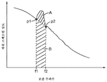
일반적인 접근법은 고속 푸리에 변환(Fast Fourier Transform, FFT) 함수를 사용하여 공간 주파수 성분을 분석하는 것이다. 토포그래피가 두 개의 직교 평면내 방향(x 및 y)을 따라 높이 정보를 제공하기 때문에, 표면의 공간 주파수 성분은 평면내 방향 각각을 따라 공간 주파수 성분을 분석함으로써 완전히 특성화된다. 구조화된 표면의 충분히 크고 대표적인 부분에 걸쳐 토포그래피를 측정하고 각각의 평면내 방향에 대해 푸리에 파워 스펙트럼을 계산함으로써 공간 주파수 성분이 결정될 수 있다. 이어서 두 개의 생성된 파워 스펙트럼을 파워 스펙트럼 밀도(PSD) 대 공간 주파수의 그래프 상에 플로팅될 수 있다. 생성된 곡선이 (영주파수에 대응하지 않는) 임의의 국소 주파수 피크를 포함하면, 그러한 피크의 크기는 도 7과 관련하여 다른 곳에 추가로 설명되는 "피크비"에 관하여 표현될 수 있다.A common approach is to analyze spatial frequency components using Fast Fourier Transform (FFT) functions. Since topography provides height information along two orthogonal in-plane directions (x and y), the spatial frequency component of the surface is fully characterized by analyzing spatial frequency components along each in-plane direction. The spatial frequency component can be determined by measuring the topography over a sufficiently large and representative portion of the structured surface and calculating the Fourier power spectrum for each in-plane direction. The two generated power spectra can then be plotted on a graph of power spectral density (PSD) versus spatial frequency. If the generated curve contains any local frequency peaks (not corresponding to zero frequency), the magnitude of such peaks may be expressed in terms of the "peak ratio" which is further described elsewhere in connection with FIG.
푸리에 파워 스펙트럼을 결정하기 위한 상세한 절차는 국제 특허 출원 공개 WO 2014/081693호(팜 등)에 설명되어 있다. 이러한 접근에서, 주어진 확산기 샘플에 대해, 샘플의 중심 부분으로부터 샘플의 약 1×1 cm의 피스를 절단한다. 샘플 피스를 현미경 슬라이드 상에 장착하고, 특성화하기 위한 그의 구조화된 표면을 Au-Pd 스퍼터-코팅한다. 공초점 주사 레이저 현미경(CSLM)을 사용하여 구조화된 표면의 두 개의 높이 프로파일을 얻는다. 가능할 때마다, 토포그래피의 우수한 샘플링 및 존재하는 임의의 주기성을 제공하도록 시야를 선택한다. 각각의 2D 높이 프로파일에 대해 2차원(2D) 파워 스펙트럼 밀도(PSD)를 계산한다. 2D PSD는 2D 높이 프로파일 H(x, y)의 2D 공간 푸리에 변환의 크기의 제곱이다. MATLAB을 사용하여, MATLAB의 고속 푸리에 변환(FFT) 함수를 사용해서 PSD를 계산한다. FFT를 사용하기 전에, 2D 높이 프로파일의 유한 공간 치수에 의해 야기되는 FFT의 링잉(ringing)을 감소시키는 데 도움을 주기 위해 2D 해밍 윈도우(Hamming window)를 2D 높이 프로파일에 적용한다. 2D PSD를 x-방향으로 합해 y-방향(웨브 하류 방향일 수 있음)으로 1차원(1D) PSD를 제공한다. 마찬가지로, 2D PSD를 y-방향으로 합해 x-방향(웨브 교차 방향일 수 있음)으로 1D PSD를 제공한다.Detailed procedures for determining the Fourier power spectrum are described in International Patent Application Publication No. WO 2014/081693 (Palm et al.). In this approach, for a given diffuser sample, about 1 x 1 cm of the sample is cut from the center portion of the sample. A sample piece is mounted on a microscope slide and its structured surface for characterization is Au-Pd sputter-coated. A confocal scanning laser microscope (CSLM) is used to obtain two height profiles of the structured surface. Whenever possible, the field of view is selected to provide superior sampling of the topography and any periodicity present. The two-dimensional (2D) power spectral density (PSD) is calculated for each 2D height profile. The 2D PSD is the square of the magnitude of the 2D spatial Fourier transform of the 2D height profile H (x, y). Using MATLAB, calculate the PSD using the Fast Fourier Transform (FFT) function in MATLAB. Before using the FFT, a 2D Hamming window is applied to the 2D height profile to help reduce the ringing of the FFT caused by the finite spatial dimension of the 2D height profile. The 2D PSDs are summed in the x-direction to provide a one-dimensional (1D) PSD in the y-direction (which can be in the web downstream direction). Likewise, the 2D PSDs are summed in the y-direction to provide a 1D PSD in the x-direction (which can be in the web intersection direction).
이제 공간 주파수 피크에 관한 1D PSD의 분석을 도 7과 관련하여 설명할 것이다. 그 도면에, 가상 푸리에 파워 스펙트럼 곡선이 예시적인 목적을 위해 도시된다. 위에서 논의된 1D PSD 함수(x 또는 y) 중 어느 하나를 나타낼 수 있는 곡선이 파워 스펙트럼 밀도(PSD) 대 공간 주파수의 그래프 상에 나타난다. 수직축(PSD)은 0에서 시작하여 선형 스케일로 플로팅되는 것으로 가정된다. 곡선은 (a) 영주파수에 대응하지 않는 그리고 (b) 기준선을 한정하는 두 개의 인접한 밸리에 의해 경계지어지는 주파수 피크를 갖는 것으로 도시된다. 두 개의 인접한 밸리는 공간 주파수 f1에서의 점 p1과 공간 주파수 f2에서의 p2에 의해 식별된다. 주파수 f1는 피크가 시작되는 주파수로 고려될 수 있고, 주파수 f2는 피크가 종료되는 주파수로 고려될 수 있다. 기준선은 p1과 p2를 연결하는 직선 선분(파선)이다. 피크의 크기는 그래프 상의 영역 A 및 B에 관하여 표현될 수 있다. 영역 A는 주파수 피크와 기준선 사이의 영역이다. 영역 B는 기준선 아래의 또는 밑의 영역이다. 즉, B = (PSD(f1) + PSD(f2))*(f2-f1)/2이다. 합 A+B는 주파수 피크 아래의 또는 밑의 영역이다. 이들 정의가 주어지면, 이제 피크의 크기는 다음과 같이 상대 피크 진폭 또는 "피크비"에 관하여 정의될 수 있다:The analysis of the 1D PSD with respect to the spatial frequency peak will now be described with reference to FIG. In the figure, an imaginary Fourier power spectrum curve is shown for illustrative purposes. A curve that can represent any of the 1D PSD functions (x or y) discussed above appears on the graph of power spectral density (PSD) vs. spatial frequency. The vertical axis (PSD) is assumed to be plotted on a linear scale starting at zero. The curve is shown to have a frequency peak bounded by two adjacent valleys that (a) do not correspond to the zero frequency and (b) define the baseline. Two adjacent valleys are identified by point p1 at spatial frequency f1 and p2 at spatial frequency f2. The frequency f1 can be considered as the frequency at which the peak starts, and the frequency f2 can be considered as the frequency at which the peak ends. The baseline is a straight line segment (dashed line) connecting p1 and p2. The magnitude of the peak can be expressed in terms of the areas A and B on the graph. Region A is the region between the frequency peak and the baseline. Region B is the area below or below the baseline. That is, B = (PSD (f1) + PSD (f2)) * (f2-f1) / 2. The sum A + B is the area below or below the frequency peak. Given these definitions, the magnitude of the peak can now be defined with respect to the relative peak amplitude or "peak ratio" as follows:
피크비 = A/(A + B).Peak ratio = A / (A + B).
각각의 샘플에 대해 두 개의 1D PDS(두 개의 푸리에 파워 스펙트럼 - 하나는 x-방향에 대해, 하나는 y-방향에 대해)가 구해질 수 있고, 푸리에 파워 스펙트럼이 임의의 주파수 피크를 포함하는 정도 내에서, 각각의 곡선에 대한 가장 현저한 피크가 식별될 수 있다. 이어서 각각의 곡선에 대한 가장 현저한 피크에 대해 전술된 피크비가 계산될 수 있다. 가장 현저한 피크가 측정되기 때문에, 계산된 피크비는 주어진 푸리에 파워 스펙트럼 내에 존재할 수 있는 모든 피크에 대한 상한치이다. 이러한 방식으로 피크비가 결정되는 예는 국제 특허 출원 공개 WO 2014/081693호(팜 등)에 설명되어 있다.For each sample, two 1D PDSs (two Fourier power spectra - one for the x-direction and one for the y-direction) can be obtained and the degree to which the Fourier power spectrum includes any frequency peaks The most prominent peak for each curve can be identified. The peak ratios described above can then be calculated for the most prominent peaks for each curve. Since the most prominent peak is measured, the calculated peak ratio is the upper limit for all peaks that may be present in a given Fourier power spectrum. An example in which the peak ratio is determined in this manner is described in International Patent Application Publication No. WO 2014/081693 (Palm et al.).
일부 실시예들에서, 제1 주 표면은 각각의 제1 및 제2 직교 평면내 방향과 관련된 제1 및 제2 푸리에 파워 스펙트럼에 의해 특성화가 가능한 토포그래피를 가지고, 제1 푸리에 파워 스펙트럼이 영주파수에 대응하지 않는 그리고 제1 기준선을 한정하는 두 개의 인접한 밸리에 의해 경계지어지는 하나 이상의 제1 주파수 피크를 포함하는 정도 내에서, 임의의 그러한 제1 주파수 피크는 0.8 미만 또는 0.7 미만의 제1 피크비를 갖고, 제2 푸리에 파워 스펙트럼이 영주파수에 대응하지 않는 그리고 제2 기준선을 한정하는 두 개의 인접한 밸리에 의해 경계지어지는 하나 이상의 제2 주파수 피크를 포함하는 정도 내에서, 임의의 그러한 제2 주파수 피크는 0.8 미만 또는 0.7 미만의 제2 피크비를 갖는다.In some embodiments, the first major surface has a topography that can be characterized by first and second Fourier power spectra associated with respective first and second orthogonal in-plane directions, wherein the first Fourier power spectrum is at a zero frequency Any such first frequency peak is within the range of less than 0.8 or less than 0.7, such that the first peak has a first peak that is less than 0.8 or less than 0.7, Of the first Fourier spectrum and the second Fourier power spectrum comprises one or more second frequency peaks bounded by two adjacent valleys that do not correspond to the zero frequency and define a second baseline, The frequency peak has a second peak ratio of less than 0.8 or less than 0.7.
본 발명의 확산기들의 제1 또는 제2 주 표면 중 어느 하나를 특성화하는 또 다른 양은 표면의 경사도 분포이다. 비교적 얕은 경사도(예를 들어, 40도 미만의 대부분의 경사도)를 갖는 것이 요구되는 실시예들에서, 경사도 분포는 제2 주 표면의 특히 유용한 특성화를 제공한다. 일부 실시예들에서, 제2 주 표면의 제2 부분의 약 20% 이하 또는 약 10% 이하 또는 약 7% 이하 또는 약 5% 이하 또는 약 3% 이하는 약 20도 초과, 약 15도 초과, 약 10도 초과 또는 약 7도 초과 또는 약 5도 초과 또는 약 3.5도 초과의 경사도 크기를 갖는다. 일부 실시예들에서, 제2 표면 주 표면은 가파른 경사도를 가질 수 있다. 예를 들어, 일부 실시예들에서, 제2 주 표면의 약 20% 이하, 약 10% 이하, 약 7% 이하는 약 20도 초과 또는 약 30도 초과 또는 약 35도 초과 또는 약 40도 초과의 경사도 크기를 갖는다. 일부 실시예들에서, 제2 주 표면의 상당한 분율은 1도 초과의 경사도 크기를 갖고, 제2 주 표면의 상당한 분율은 10도 미만 또는 15도 미만의 경사도 크기를 갖는다. 일부 실시예들에서, 제2 주 표면의 제2 부분의 약 50% 이상 또는 약 70% 이상 또는 약 80% 이상 또는 약 85% 이상 또는 약 90% 이상은 1도 초과의 경사도 크기를 갖는다. 일부 실시예들에서, 제2 주 표면의 제2 부분의 약 85% 이하 또는 약 80% 이하는 약 15도 초과이거나 약 10도 초과의 경사도 크기를 갖는다.Another quantity that characterizes either the first or second major surface of the diffusers of the present invention is the gradient of the surface gradient. In embodiments where it is desired to have a relatively shallow slope (e.g., most slope less than 40 degrees), the slope distribution provides a particularly useful characterization of the second major surface. In some embodiments, no greater than about 20%, or no greater than about 10%, or no greater than about 7%, or no greater than about 5%, or no greater than about 3% of the second portion of the second major surface is greater than about 20 degrees, Greater than about 10 degrees, or greater than about 7 degrees, or greater than about 5 degrees, or greater than about 3.5 degrees. In some embodiments, the second surface major surface may have a steep slope. For example, in some embodiments, no greater than about 20%, no greater than about 10%, no greater than about 7% of the second major surface is greater than about 20 degrees, or greater than about 30 degrees, or greater than about 35 degrees, And has an inclination size. In some embodiments, a substantial fraction of the second major surface has a gradient magnitude of greater than one degree and a substantial fraction of the second major surface has a gradient magnitude of less than 10 degrees or less than 15 degrees. In some embodiments, about 50% or more, or about 70% or more, or about 80% or more, or about 85% or more, or about 90% or more of the second portion of the second major surface has an inclination size of more than 1 degree. In some embodiments, about 85% or less, or about 80% or less, of the second portion of the second major surface has a tilt magnitude of greater than about 15 degrees or greater than about 10 degrees.
도 8은 구조화된 층(840)의 일부분의 개략적 측면도이다. 예를 들어, 구조화된 층(840)은 도 2a의 제2 층(236)에 대응할 수 있다. 도 8은 주 표면(842)의 반대편에 있는 주 표면(814) 내의 미세 구조일 수 있는 구조체(860)를 도시한다. 구조체(860)는 구조체의 표면을 가로지르는 경사도 분포를 갖는다. 예를 들어, 구조체는 위치(810)에서 경사도(□)를 가지며, 여기서 □은 위치(810)에서 구조화된 표면에 수직인 법선(820)(□ = 90도)과 동일한 위치에서 구조체(860)의 표면에 접하는 접선(830) 사이의 각도이다. 경사도(□)는 또한 접선(830)과 층(840)의 주 표면(842) 사이의 각도이다.8 is a schematic side view of a portion of the structured
제1 또는 제2 주 표면은 예를 들어, 표면 프로파일 H(x, y)(즉, 직교하는 평면내 좌표 x 및 y의 함수로서 기준 평면 위의 표면의 높이 H)를 결정하기 위해 AFM 또는 CSLM을 사용하여 특성화될 수 있다. 이어서, 각각의 x-방향 및 y-방향을 따른 경사도 Sx 및 Sy가 아래의 두 개의 표현들로부터 계산될 수 있다:The first or second major surface may be, for example, an AFM or CSLM to determine the surface profile H (x, y) (i.e., the height H of the surface above the reference plane as a function of orthogonal in-plane coordinates x and y) ≪ / RTI > Then, the slopes S x and S y along the respective x-direction and y-direction can be calculated from the following two expressions:

경사도 크기 Sm은 아래의 표현으로부터 계산될 수 있다:The slope size S m can be calculated from the following expression:

x-방향으로의 경사도, y-방향으로의 경사도, 및 경사도 크기의 분포들이 결정될 수 있다.the tilt in the x-direction, the tilt in the y-direction, and the distribution of the tilt magnitude can be determined.
일부 실시예들에서, 제2 주 표면의 제1 부분의 적어도 하나의 영역 또는 제2 주 표면의 제2 부분의 적어도 하나의 영역은 제1 방향으로 HWHM(first half width at half maximum)을 갖는 제1 표면각 분포를 가지고(예컨대, x-방향으로의 경사도 Sx의 분포는 σx의 HWHM을 가질 수 있음), 제1 방향과 상이한 제2 방향으로 제2 HWHM을 갖는 제2 표면각 분포를 갖는 제1 표면각 분포를 갖는다(예컨대, y-방향으로의 경사도 Sy의 분포는 σy의 HWHM을 가질 수 있음). 일부 실시예들에서, 제1 HWHM은 제2 HWHM과 실질적으로 동일하고, 일부 실시예들에서 제1 HWHM은 제2 HWHM과 상이하다. 예를 들어, |σx -σy|는 약 1도 내지 약 5도 또는 약 10도 또는 약 15도의 범위 내에 있을 수 있다. 일부 실시예들에서, σx 및 σy 각각은 약 1도 내지 약 10도 또는 약 15도의 범위 내에 있다. 일부 실시예들에서, σx와 σy 중 더 큰 것 대 σx와 σy 중 더 작은 것의 비는 1 초과 또는 1.1 초과 또는 1.2 초과 또는 1.5 초과이고, 15 미만 또는 10 미만 또는 5 미만이다. 일부 실시예들에서, |σx -σy|를 σx +σy로 나눈 값은 0.05 초과 또는 0.1 초과 또는 0.2 초과이다.In some embodiments, at least one region of the first portion of the second major surface or at least one region of the second portion of the second major surface has a first half width at half maximum (HWHM) in the first direction (E.g., the distribution of slopes S x in the x-direction may have a HWHM of? X ), a second surface angular distribution having a second HWHM in a second direction different from the first direction (E.g., the distribution of the slope S y in the y-direction may have a HWHM of? Y ). In some embodiments, the first HWHM is substantially the same as the second HWHM, and in some embodiments, the first HWHM is different from the second HWHM. For example, | sigma x- sigma y | may range from about 1 degree to about 5 degrees or about 10 degrees or about 15 degrees. In some embodiments, each of sigma x and sigma y is in the range of about 1 degree to about 10 degrees or about 15 degrees. In some embodiments, the ratio of what more of σ x and σ y whichever is greater for σ x and σ y smaller is greater than 1 or 1.1 in excess or 1.2 above or 1.5 excess, and 15 is less than or less than 10 or less than 5. In some embodiments, the value obtained by dividing | x- y | by? X + y is greater than 0.05 or greater than 0.1 or greater than 0.2.
구조체들의 분포는 구조체들의 진폭(예컨대, 피크 대 밸리 높이)을 변동하거나 인접한 구조체들 사이의 간격을 변동함으로써 변동될 수 있다. 일부 실시예들에서, 제2 주 표면은 진폭 분포 및 간격 분포를 갖는 표면 구조체들을 포함하며, 진폭 및 간격 분포 중 적어도 하나는 제2 주 표면의 제1 부분을 통해 변동되고, 진폭 및 간격 분포 각각은 제2 주 표면의 제2 부분에서 실질적으로 균일하다. 높이 분포 및/또는 간격 분포 및/또는 구조체들의 형상 분포를 변동함으로써 경사도 분포가 변동될 수 있다. 일부 실시예들에서, 제2 주 표면은 경사도 분포를 갖는 표면 구조체들을 포함하고, 경사도 분포는 제2 주 표면의 제1 부분을 통해 실질적으로 연속적으로 변동되고(예컨대, 경사도 분포는 제1 에지(223)로부터 제2 주 표면(214)의 제1 및 제2 부분들(216 및 218) 사이의 연속 경계(217)까지 실질적으로 연속적으로 변동됨), 제2 주 표면의 제2 부분에서 실질적으로 균일하다.The distribution of the structures can be varied by varying the amplitude (e.g., peak to valley height) of the structures or by varying the spacing between adjacent structures. In some embodiments, the second major surface comprises surface structures having an amplitude distribution and a spacing distribution, at least one of the amplitude and spacing distributions varying through a first portion of the second major surface, and the amplitude and spacing distributions Is substantially uniform in the second portion of the second major surface. The gradient distribution can be varied by varying the height distribution and / or the interval distribution and / or the shape distribution of the structures. In some embodiments, the second major surface includes surface structures having an inclination distribution, and the gradient distribution is substantially continuously varied through a first portion of the second major surface (e.g., the gradient distribution is at a first edge 223) to a
일부 실시예들에서, 제1 주 표면은 구조화된 표면을 갖는 공구로부터 미세복제에 의해 제조된다. 공구의 구조화된 표면은 국제 특허 출원 공개 WO 2014/081693호(팜 등)에서 설명된 바와 같이, 금속을 제1 전기도금 공정을 사용하여 전착시킴으로써 금속의 제1층을 형성하여 제1 평균 조도를 갖는 제1 층의 주 표면을 생성하고, 금속을 제2 전기도금 공정을 사용하여 제1 층 상에 전착시킴으로써 제1 층의 주 표면 상에 금속의 제2 층을 형성하여 제1 평균 조도보다 작은 제2 평균 조도를 갖는 제2 층의 주 표면을 생성함으로써 제조될 수 있으며, 제2 층의 주 표면은 도구 구조화된 표면에 대응한다.In some embodiments, the first major surface is fabricated by micro-replication from a tool having a structured surface. The structured surface of the tool can be formed by depositing a metal using a first electroplating process to form a first layer of metal, as described in International Patent Application Publication No. WO 2014/081693 (Palm et al.), And depositing a metal on the first layer using a second electroplating process to form a second layer of metal on the major surface of the first layer so that the first average roughness is less than the first average roughness A second surface having a second average roughness, and the major surface of the second layer corresponds to a tool structured surface.
도 9는 예를 들어, 확산기의 제1 주 표면과 같은 구조화된 표면을 제조하는 공정의 예시적인 버전(901)을 도시한다. 공정의 단계(902)에서, 기부 또는 기재가 제공될 수 있으며, 이는 금속 층들이 전착될 수 있는 기초로서 역할을 할 수 있다. 기재는 다양한 형태들 중 하나의 형태, 예컨대, 시트, 플레이트, 또는 실린더의 형태를 취할 수 있다. 원형 실린더들은 연속 롤 제품들을 생산하기 위해 사용될 수 있다는 점에서 유리하다. 기재는 전형적으로 금속으로 제조되고, 예시적인 금속들은 니켈, 구리, 및 황동을 포함한다. 그러나 다른 금속들 또한 사용될 수 있다. 기재는 후속 단계들에서 전기도금된 층들이 형성될 노출 표면("기부 표면")을 갖는다. 기부 표면은 매끄럽고 평평하거나 실질적으로 평평할 수 있다. 특히 실린더 표면 상의 임의의 주어진 점 부근의 작은 국부적 영역을 고려한다면, 매끄러운 폴리싱된 실린더의 만곡된 외부 표면은 실질적으로 평평한 것으로 간주될 수 있다. 기부 표면은 기부 평균 조도에 의해 특성화될 수 있다. 이와 관련하여, 기부 표면의 표면 "조도", 또는 본 발명에서 언급되는 다른 표면들의 "조도"는 평균 조도 Ra 또는 제곱 평균 제곱근(root mean squared) 조도 Rrms와 같은 임의의 일반적으로 인정된 조도 측정치를 사용하여 정량화될 수 있고, 관심 대상 표면의 전체 관련 영역을 적절히(fairly) 대표하기에 충분히 큰 영역에 걸쳐 측정되는 것으로 가정한다.FIG. 9 illustrates an
공정(901)의 단계(903)에서, 금속의 제1 층은 제1 전기도금 공정을 사용하여 기재의 기부 표면 상에 형성된다. 이 단계가 개시되기 전에, 기재의 기부 표면은 접착을 촉진시키기 위하여 프라이밍(primed)되거나 달리 처리될 수 있다. 금속은 기부 표면을 구성하고 있는 금속과 실질적으로 동일할 수 있다. 예를 들어, 기부 표면이 구리를 포함하는 경우, 단계(903)에서 형성되는 제1 전기도금된 층 또한 구리로 제조될 수 있다. 금속의 제1 층을 형성하기 위해, 제1 전기도금 공정은 제1 전기도금 용액을 사용한다. 제1 전기도금 용액의 조성, 예컨대 용액에 사용되는 금속 염의 유형, 및 전류 밀도, 도금 시간 및 기재 속도와 같은 다른 공정 파라미터들은 제1 전기도금된 층이 매끄럽고 평평하게 형성되는 것이 아니라 대신에 구조화되고, 불규칙한 평평-패싯형 특징부들에 의해 특성화되는 제1 주 표면을 갖도록 선택된다. 불규칙한 특징부들의 크기 및 밀도는 전류 밀도, 도금 시간 및 기재 속도에 의해 결정되는 한편, 제1 전기도금 용액에 사용되는 금속 염의 유형은 특징부들의 기하학적 구조를 결정한다. 이와 관련된 추가의 교시 내용을 미국 특허 출원 공개 제2010/0302479호(아론슨 등)에서 찾아볼 수 있다. 제1 도금 공정은 제1 전기도금된 층의 제1 주 표면이 기재의 기부 평균 조도 초과의 제1 평균 조도를 갖도록 수행된다.In
단계(903)에서 금속의 제1 전기도금된 층이 제1 평균 조도의 그의 구조화된 주 표면을 갖고서 제조된 후에, 단계(904)에서 금속의 제2 전기도금된 층이 제2 전기도금 공정을 사용하여 형성된다. 금속의 제2 층은 제1 전기도금된 층을 덮고, 이들의 조성이 실질적으로 동일할 수 있기 때문에, 두 개의 전기도금된 층들은 더 이상 구별가능하지 않을 수 있으며, 제1 층의 제1 주 표면은 실질적으로 없어질 수 있고 더 이상 검출가능하지 않을 수 있다. 그럼에도 불구하고, 제2 전기도금 공정은 제2 전기도금된 층의 노출된 제2 주 표면이 비록 구조화되고 평평하지 않지만 제1 주 표면의 제1 평균 조도보다 작은 제2 평균 조도를 갖는다는 방식으로 제1 전기도금 공정과 상이하다. 제2 전기도금 공정은 제1 주 표면에 비해 감소된 조도를 갖는 제2 주 표면을 제공하기 위해 여러 가지 측면에서 제1 전기도금 공정과 상이할 수 있다.After the first electroplated layer of metal is prepared with its structured major surface of first average roughness in
일부 경우들에서, 단계(904)의 제2 전기도금 공정은 적어도 박스(904a)로 도시된 유기 레벨러(leveler)의 첨가만큼 단계(903)의 제1 전기도금 용액과 상이한 제2 전기도금 용액을 사용할 수 있다. 유기 레벨러는 작은 표면 불규칙부의 깊이 또는 높이의 궁극적인 감소를 갖고서 침착물을 작은 리세스(recess) 내에 상대적으로 더 두껍게 그리고 작은 돌출부 상에 상대적으로 더 얇게 생성하는 능력을 도금욕(plating bath)에 도입하는 재료이다. 레벨러에 의해, 도금된 부분이 기저 금속보다 큰 표면 평활도를 가질 것이다. 예시적인 유기 레벨러는 술폰화, 황화 하이드로카빌 화합물; 아릴 술폰산; 다양한 종류의 폴리에틸렌 글리콜; 및 바이티오카바메이트 또는 티오우레아 및 이들의 유도체를 비롯한 티오카바메이트를 포함할 수 있지만 이에 제한되지 않는다. 제1 전기도금 용액은 많아야 미량의 유기 레벨러를 함유할 수 있다. 제1 전기도금 용액은 100 또는 75 또는 50 ppm 미만의 유기 탄소의 총 농도를 가질 수 있다. 제2 전기도금 용액 내의 유기 레벨러의 농도 대 제1 전기도금 용액 내의 임의의 유기 레벨러의 농도의 비는 예를 들어 50 또는 100 또는 200 또는 500 이상일 수 있다. 제2 주 표면의 평균 조도는 제2 전기도금 용액 내의 유기 레벨러의 양을 조절함으로써 맞추어질 수 있다.In some cases, the second electroplating process of
단계(904)의 제2 전기도금 공정은 또한 또는 대안적으로 그 효과가 제1 주 표면에 비해 제2 주 표면의 조도를 감소시키는 것인 적어도 하나의 전기도금 기술 또는 특징을 제2 단계(904)에 포함시킴으로써 단계(903)의 제1 전기도금 공정과 상이할 수 있다. 시빙(thieving)(박스(904b)) 및 실딩(shielding)(박스(904c))이 그러한 전기도금 기술 또는 특징의 예이다. 또한, 유기 레벨러에 더하여 또는 그 대신에, 하나 이상의 유기 입자 미세화제(박스(904d))가 제2 주 표면의 평균 조도를 감소시키기 위해 제2 전기도금 용액에 첨가될 수 있다.The second electroplating process of
단계(904)가 완료된 후에, 제1 및 제2 전기도금된 층을 갖는 기재는 광학 확산 필름을 형성하기 위한 원 공구(original tool)로서 사용될 수 있다. 일부 경우들에서, 공구의 구조화된 표면, 즉 단계(904)에서 생성된 제2 전기도금된 층의 구조화된 제2 주 표면은 제2 금속 또는 다른 적합한 재료로 부동태화되거나 달리 보호될 수 있다. 예를 들어, 제1 및 제2 전기도금된 층이 구리로 구성되는 경우, 구조화된 제2 주 표면은 크롬의 얇은 코팅으로 전기도금될 수 있다. 크롬 또는 다른 적합한 재료의 얇은 코팅은 바람직하게는 구조화된 제2 주 표면의 토포그래피 및 평균 조도를 실질적으로 보존하기에 충분히 얇다.After
광학 확산 필름의 제조에 원 공구 그 자체를 사용하기보다는, 원 공구의 구조화된 제2 주 표면을 미세복제함으로써 하나 이상의 복제 공구가 제조될 수 있고, 이어서 이러한 복제 공구(들)가 확산기의 구조화된 표면을 제조하기 위해 사용될 수 있다. 원 공구로부터 제조된 제1 복제물이 구조화된 제2 주 표면에 대응하지만 그의 역 형태인 제1 복제 구조화된 표면을 가질 것이다. 예를 들어, 구조화된 제2 주 표면 내의 돌출부가 제1 복제 구조화된 표면 내의 공동에 대응한다. 제2 복제물이 제1 복제물로부터 제조될 수 있다. 제2 복제물은 원 공구의 구조화된 제2 주 표면에 대응하고 그의 비-역 형태인 제2 복제 구조화된 표면을 가질 것이다.Rather than using the original tool itself in the manufacture of the optical diffusing film, one or more duplicate tools can be manufactured by micro-copying the structured second major surface of the original tool, and then such duplicate tool (s) Can be used to make the surface. A first replica made from the original tool will have a first replicated structured surface corresponding to the structured second major surface but in its inverse form. For example, protrusions in the structured second major surface correspond to cavities in the first replicated structured surface. A second copy may be made from the first copy. The second replica will have a second replicated structured surface that corresponds to the structured second major surface of the original tool and is in its non-inverted form.
단계(904) 후에, 구조화된 표면 공구가 제조된 후에, 단계(906)에서 원 또는 복제 공구로부터 미세복제에 의해 동일한 구조화된 표면(원 공구에 대해 역이든지 비-역이든지 간에)을 갖는 광학 확산 필름이 제조될 수있다. 구조화된 제1 주 표면은 예컨대 예비성형된 필름을 엠보싱하는 공정, 또는 경화성 층을 캐리어 필름 상에 주조 및 경화시키는 공정을 비롯한 임의의 적합한 공정을 사용하여 공구로부터 형성될 수 있다.After
도 10은 예를 들어, 가변 탁도를 갖는 제2 주 표면의 것과 같은, 구조화된 표면을 생성하기 위하여 미세복제될 수 있는 공구를 절단하기 위해 사용할 수 있는 절삭 공구 시스템(1000)의 개략적 측면도이다. 절삭 공구 시스템(1000)은 스레드 컷(thread cut) 선삭 공정을 사용하고, 구동기(1030)에 의해 중심축(1020)을 중심으로 회전하고/하거나 이를 따라 이동할 수 있는 롤(1010), 및 롤 재료를 절삭하기 위한 커터(1040)를 포함한다. 커터는 서보(1050) 상에 장착되고, 구동기(1060)에 의해 x-방향을 따라 롤 내로 이동되고/되거나 롤을 따라 이동될 수 있다. 일반적으로, 커터(1040)는 롤 및 중심축(1020)에 수직으로 장착되고, 롤이 중심축 주위로 회전하는 동안 롤(1010)의 각인가능한 재료 내로 구동된다. 이어서, 커터는 중심축에 평행하게 구동되어 스레드 컷을 생성한다. 커터(1040)는 예를 들어, 미세복제될 때 구조체(860)를 형성하는 특징부들을 롤 내에 생성하도록 높은 빈도 및 낮은 변위로 동시에 작동될 수 있다.10 is a schematic side view of a
서보(1050)는 고속 공구 서보(FTS)이며, 커터(1040)의 위치를 신속하게 조정하는, 종종 PZT 적층체로 지칭되는 고상 압전 장치(solid state piezoelectric(PZT) device)를 포함한다. FTS(1050)는 x-방향, y-방향 및/또는 z-방향, 또는 축외(off-axis) 방향으로의 커터(1040)의 매우 정밀하면서도 고속의 이동을 가능하게 한다. 커터(1040)는 x-방향, y-방향 및/또는 z-방향으로 이동할 수 있기 때문에, x-방향과 y-방향 중 어느 하나 또는 둘 모두에서 변동되는 진폭들 또는 경사도들의 분포를 갖는 구조화된 표면들이 형성될 수 있다. 서보(1050)는 휴지 위치(rest position)에 대한 제어된 이동을 발생시킬 수 있는 임의의 고품질 변위 서보일 수 있다. 일부 경우들에서, 서보(1050)는 약 0.1 마이크로미터 또는 더 우수한 분해능으로 0 내지 약 20 마이크로미터 범위 내의 변위를 확실하게 그리고 반복가능하게 제공할 수 있다.The
구동기(1060)는 중심축(1020)에 평행한 x-방향을 따라 커터(1040)를 움직일 수 있다. 일부 경우들에서, 구동기(1060)의 변위 분해능은 약 0.1 마이크로미터보다 더 양호하거나, 약 0.01 마이크로미터보다 더 양호하다. 구조체들(860)의 최종 형상을 정확하게 제어하기 위해, 구동기(1030)에 의해 생성되는 회전 운동은 구동기(1060)에 의해 생성되는 병진 운동과 동기화된다.The
절삭 공구 시스템(1000)은 구조화된 제1 주 표면(212)(도 2a 참조)을 형성하기 위해 사용될 수 있는 공구를 제조하기 위해 사용될 수 있고/있거나, 절삭 공구 시스템(1000)은 구조화된 제2 주 표면(214)을 형성하기 위해 사용될 수 있는 공구를 제조하기 위해 사용될 수 있다. 구조화된 제2 주 표면(214)을 형성하기 위한 공구를 제조하기 위해 사용되는 경우에, 구동기(1030)에 의해 생성되는 회전 운동 및 구동기(1060)에 의해 생성되는 병진 운동은, 구조화된 제2 주 표면(214)의 제1 부분(216)에 대응되는 공구의 일부분의 진폭 분포, 간격 분포, 구조체 형상 분포 및 경사도 분포 중 하나 이상에서의 변위를 생성하도록 선택된다.The
롤(1010)의 각인가능한 재료는 커터(1040)에 의해 각인될 수 있는 임의의 재료일 수 있다. 예시적인 롤 재료는 구리와 같은 금속, 다양한 중합체, 및 다양한 유리 재료를 포함한다. 커터(1040)는 임의의 유형의 커터일 수 있고, 응용에 바람직할 수 있는 임의의 형상을 가질 수 있다. 적합한 절단기들이 미국 특허 제8,657,472호(아론슨 등) 또는 제8,888,333호(야펠 등)에 설명되어 있다.The stampable material of the
구조화된 제2 주 표면은, 예컨대 사전 형성된 필름을 엠보싱하는 공정, 기재 상에 경화가능한 층을 주조 및 경화하는 공정을 비롯한 임의의 적합한 공정을 사용하여, 생성된 공구로부터 형성될 수 있다. 본 발명의 다른 곳에서 설명되는 바와 같이, 원 공구 또는 공구의 복제물은 구조화된 표면을 형성하기 위해 사용될 수 있다.The structured second major surface can be formed from the resulting tool, for example, using any suitable process, including embossing the preformed film, casting and curing the curable layer on the substrate. As described elsewhere herein, a copy of the original tool or tool can be used to form the structured surface.
일부 실시예들에서, 광학 필름 및 광학 필름과 실질적으로 동연적인 본 발명의 광학 확산기들 중 임의의 광학 확산기 - 확산기의 구조화된 상부 표면(예컨대, 제1 주 표면(112 또는 212))이 광학 필름의 구조화된 하부 표면에 대면함 - 를 포함하는 광학 스택이 제공된다. 광학 필름은 제1 방향을 따라 선형으로 연장되는 복수의 실질적으로 평행한 상부 구조체들을 포함하는 구조화된 상부 표면; 및 제1 방향과 상이한 제2 방향을 따라 선형적으로 연장되는 실질적으로 평행한 복수의 하부 구조체들을 포함하는 구조화된 하부 표면을 포함할 수 있으며, 각각의 상부 및 하부 구조체는 구조체의 기부의 서로 반대편에 있는 제1 및 제2 단부들 각각으로부터 연장되어 구조체의 피크에서 만나는 서로 반대편에 있는 제1 및 제2 만곡면들을 포함한다. 일부 실시예들에서, 광학 필름 및 광학 확산기는 광학 필름과 광학 확산기 사이에 에어 갭을 형성하도록 그들의 대응 에지들을 따라 함께 접합된다. 일부 실시예들에서, 구조화된 상부 및 하부 표면 각각은 실질적으로 무작위로 배열되는 복수의 구조체들을 포함한다. 일부 실시예들에서, 광학 확산기는, 광학 필름의 구조화된 하부 표면에 대면하고, 구조화된 상부 표면을 가로질러 실질적으로 균일한 제1 광학 탁도를 갖는 구조화된 상부 표면; 및 구조화된 하부 표면 - 구조화된 하부 표면은 구조화된 하부 표면의 제1 에지를 따른 제1 부분 및 구조화된 하부 표면의 제1 영역으로부터 반대편 제2 에지까지 연장되는 제2 부분을 가짐 - 을 포함하며, 제1 부분의 적어도 일부 영역들은 제1 광학 탁도 이상의 제3 광학 탁도를 가지고, 제2 부분은 제2 부분을 가로질러 실질적으로 균일한 제2 광학 탁도를 가지며, 제2 광학 탁도는 제1 광학 탁도 미만이다. 일부 실시예들에서, 상부 표면의 제1 광 탁도는 실질적으로 균일하고 약 70% 초과이고, 확산기의 제1 부분의 제1 영역에서의 제3 광학 탁도는 약 95% 초과이며, 제2 주 표면의 제2 부분의 제2 광학 탁도는 실질적으로 균일하고 약 70% 미만이다.In some embodiments, the structured upper surface (e.g., the first
일부 실시예들에서, 백라이트가 제공되며, 이는 광원, 광원에 근접한 입력 표면 및 출력 표면을 갖는 도광체, 도광체 상에 배치된 본 발명의 광학 확산기들 중 임의의 광학 확산기, 및 광학 확산기 상에 배치된 광학 필름을 포함한다. 일부 실시예들에서, 광학 확산기는 구조화된 상부 표면을 가로질러 실질적으로 균일한 제1 광학 탁도를 갖는 구조화된 상부 표면; 및 도광체의 출력 표면에 대면하는 구조화된 하부 표면을 가지며, 구조화된 하부 표면은 도광체의 입력 표면에 근접한 구조화된 하부 표면의 제1 에지를 따른 제1 부분 및 구조화된 하부 표면의 제1 부분으로부터 반대편 제2 에지까지 연장되는 제2 부분을 가지고, 제1 부분의 적어도 제1 영역은 제1 광학 탁도 이상의 제3 광학 탁도를 가지며, 제2 부분은 제2 부분을 가로질러 실질적으로 균일한 제2 광학 탁도를 가지며, 제2 광학 탁도는 제1 광학 탁도와 상이하다. 광학 필름은 광학 확산기의 구조화된 상부 표면에 대면하는 복수의 실질적으로 선형의 평행한 제1 구조체들을 포함하는 제1 구조화된 표면; 광학 확산기의 구조화된 상부 표면으로부터 멀어지는 방향으로 대면하는 복수의 실질적으로 선형의 평행한 제2 구조체들을 포함하는 제2 구조화된 표면을 포함하며, 각각의 제1 및 제2 구조체는 대향하는 만곡된 제1 및 제2 면들을 포함하며, 만곡된 제1 및 제2 면들은 상이한 곡률의 축을 갖는다.In some embodiments, a backlight is provided that includes a light source, a light guide having an input surface proximate to the light source and an output surface, any optical diffuser of the present invention optical diffusers disposed on the light guide, And an optical film disposed thereon. In some embodiments, the optical diffuser comprises a structured top surface having a first optical turbidity substantially uniform across the structured top surface; And a structured lower surface facing the output surface of the light guide, the structured lower surface comprising a first portion along a first edge of the structured lower surface proximate the input surface of the light guide and a first portion along the first edge of the structured lower surface, At least a first region of the first portion having a third optical turbidity above the first optical turbidity and a second portion having a substantially uniform distribution across the second portion, 2 optical turbidity, and the second optical turbidity is different from the first optical turbidity. The optical film comprises a first structured surface comprising a plurality of substantially linear parallel first structures facing the structured upper surface of the optical diffuser; And a second structured surface comprising a plurality of substantially linear parallel second structures facing away from the structured top surface of the optical diffuser, each first and second structure having an opposing curved < RTI ID = 0.0 > 1 and second sides, wherein the curved first and second sides have different curvature axes.
도 17은 본 발명의 확산기들과 함께 유리하게 사용될 수 있는 예시적인 광학 필름의 분할 전방측 입면 단면도이다. 광학 필름(1700)은 미세구조체(1712)를 갖는 상부 구조화된 표면(1710) 및 제 1면(1722) 및 제 2면(1724)을 갖는 미세구조체들을 갖는 하부 구조화된 표면(1720)을 포함한다.17 is a fragmented front side elevation cross-sectional view of an exemplary optical film that can be advantageously used with the diffusers of the present invention. The
도 17에서, 구조화된 표면들(상부 구조화된 표면(1710) 및 하부 구조화된 표면(1720))은 미세구조체들의 길이 방향이 일반적으로 평행하지 않도록 배치된다. 일부 실시예들에서, 미세구조체들의 길이 방향이 서로 직교하도록 배향된다. 그러나, 상부 및 하부 구조화된 표면들 모두의 동시 단면을 더 쉽게 묘사하기 위해, 도17은 (도 18과 함께) 분할 전방측 입면 단면도로서; 즉, 각 구조화된 표면 왼쪽의 기준 좌표계가 제시하는 바와 같이, 도면들은 실제로 두 개의 사시도들이 함께 이어진 것이다.In Fig. 17, the structured surfaces (
상부 구조화된 표면(1710)은 미세구조체(1712)를 포함한다. 일부 실시예들에서, 구조화된 상부 표면은 복수의 평행 미세구조체들을 포함한다. 일부 실시예들에서, 평행 미세구조체들은 선형 미세구조체들일 수 있다. 선형이라는 말은 미세구조체들 중 하나의 미세구조체의 피크가 (예를 들어, 상부 평면도에서 보는 경우에) 상부 구조화된 표면을 가로질러 선이라는 것을 의미한다. 일부 실시예들에서, 그리고 제조 공정의 한계를 포함하는 실질적인 이유로, 선형 미세구조체들은 정밀한 선형에서 작은 편차를 포함할 수 있다. 일부 실시예들에서, 미세구조체들은 선형이되, 피치가 주기적 또는 비주기적으로 변동할 수 있다. 일부 실시예들에서, 미세구조체들은 선형일 수 있으나, 높이가 주기적 또는 비주기적으로 변동할 수 있다. 일부 실시예들에서, 인접하는 미세구조체들 사이에 공간 또는 "랜드(land)"가 있을 수 있다. 일부 실시예들에서, 상부 구조화된 표면(1710)은 인접한 미세구조체들 사이에 약 0.5 ㎛ 내지 약 5 ㎛ 범위 내의 간격을 포함한다. 간격은 일정하거나 가변될 수 있다.The
미세구조체(1712)는 실질적으로 만곡될 수 있다. 일부 실시예들에서, 미세구조체들(1712)은 실질적으로 원통 또는 반원통 형상을 갖는다. 일부 실시예들에서, 미세구조체(1712)는 미세구조체의 길이에 직교하는 단면을 따라 반원 또는 반타원이다. 일부 실시예들에서, 미세구조체(1712)는 미세구조체(1712)의 기부에 직교하는 선을 따라, 미세구조체(1712)의 피크로부터 미세구조체(1712)의 기부까지 측정되는 높이(h)에 의해 특성화된다. 상부 구조화된 표면(1710) 상의 최저점들은 미세구조체(1712)의 기부를 결정하기 위해 사용될 수 있다. 미세구조체(1712)는 또한 곡률 반경(R)에 의해 특성화될 수 있고, h/R 비는 임의의 적합한 값일 수 있다. 일부 실시예들에서, h/R은 0.4 이하이다.The
일부 실시예들에서, 구조체들이 연장되는 방향을 가로질러 취해진 구조체의 면의 모든 단면들에 대한 곡률 중심들은 함께 고려되며, 곡률의 "축"으로서 지칭될 수 있다. 일부 실시예들에서, 만곡면들의 곡률축은 상이하다.In some embodiments, the curvature centers for all the cross-sections of the surface of the structure taken across the direction in which the structures extend are considered together and can be referred to as the "axis" of curvature. In some embodiments, the curvature axes of the curved surfaces are different.
상부 구조화된 표면(1710)은 임의의 적합한 방법 및 임의의 적합한 재료로 형성될 수 있다. 예를 들어, 상부 구조화된 표면(1710)은 선택적으로 에칭되거나 연마될 수 있다. 일부 실시예들에서, 상부 구조화된 표면(1710)은 2-광자 마스터링 공정을 통해 적어도 부분적으로 형성될 수 있다. 일부 실시예들에서, 상부 구조화된 표면(1710)은 역형상화된 공구를 활용하여 주조 및 경화 공정(cast-and-cure process)에 의존한다. 일부 경우들에서, 상부 구조화된 표면은 적합한 광 노출로 수지를 경화하고, 수지를 주형 또는 공구로부터 분리, 그리고 영구적으로 그의 형상을 유지하도록 UV-가교결합성 또는 UV 경화성 수지로부터 형성될 수 있다. 일부 실시예들에서, 상부 구조화된 표면(1710)은 3D 인쇄와 같은 부가 공정을 통해 형성될 수 있다. 일부 실시예들에서, 상부 구조화된 표면(1710)은 사출 성형될 수 있다. 상부 구조화된 표면(1710)은 재료의 모놀리식 피스로 형성될 수 있거나, 기재 또는 치수적으로 안정한 또는 비틀림 저항성 층 상에 배치된 재료의 상부 층에 형성될 수 있다. 재료 또는 재료들은 투명도, 스크래치 또는 마모 저항성, 비틀림 저항성, 복굴절 또는 이의 결여, 미세복제될 능력, 탁도, 유리 전이 온도(Tg), 다른 표면들에 접합될 잠재성, 또는 임의의 다른 적합한 특성과 같은 그들의 재료적, 물리적, 또는 광학적 속성들로 인해 선택될 수 있다.The
하부 구조화된 표면(1720)은 각각 제1 면(1722) 및 제2 면(1724)을 갖는 미세구조체들을 포함한다. 상부 구조화된 표면(1710)의 경우, 미세구조체들은 선형 미세구조체들일 수 있다; 그러나, 도 17의 사시도가 분할되어 있음을 상기한다면, 이 도면에 도시된 예시적인 구성에서 상부 및 하부 구조체들의 미세구조체들은 일반적으로 서로 직교적으로 이어진다(run). 저부 구조화된 표면(1720)은 소정의 실시예들에서 0.5 ㎛ 내지 3 ㎛ 사이의 간격으로 이격된 인접 구조체들을 포함할 수 있다.The
제1 면(1722)은 실질적으로 평평하기 때문에 미세구조체의 길이에 직교하는 단면에서 보면, 제1 면은 직선으로 보인다. 다른 실시예들에서, 제1 면(1722)은 곡률도(degree of curvature)를 가질 수 있다. 제2 면(1724)은 만곡되기 때문에 미세구조체의 길이에 직교하는 단면에서 보면, 제2 면은 원호 또는 곡선으로 보인다. 일부 실시예들에서, 예를 들어 미세구조체들은 두 개 초과의 면들, 또는 두 개의 면들 및 피크 또는 접합 부분을 포함할 수 있다. 일부 실시예들에서, 제2 면(1724)은 일정한 곡률을 가질 수 있거나, 구분적(piecewise) 곡률을 가질 수 있다. 일부 실시예들에서, 제2 면(1724)은 연속적 가변 곡률을 가질 수 있다. 일부 실시예들에서, 각각의 제1 면은 동일하거나 실질적으로 동일한 형상 및 크기일 수 있다. 일부 실시예들에서, 각각의 제2 면은 동일하거나 실질적으로 동일한 형상 및 크기일 수 있다. 일부 실시예들에서, 제1 및 제2 면들 중 하나 이상은 형상, 또는 크기에서 주기적 또는 비주기적으로, 또는 구배적으로 변동될 수 있다.Because the
광학 필름(1700)은 전체적으로 임의의 적합한 재료 또는 재료들의 조합으로부터 형성될 수 있고, 임의의 적합한 치수들을 가질 수 있다. 일부 실시예들에서, 광학 필름(1700)은 특정 디스플레이 또는 조명 응용을 위해 크기 또는 형상 설정될 수 있다. 설명한 바와 같이, 광학 필름(1700)의 구조화된 표면 상의 구조체들은 직교방향으로 이어질 수 있거나, 단순히 제1 방향과 제2 방향으로 연장되거나 이어질 수 있다 - 제1 방향과 제2 방향은 서로 상이함 -. 예를 들어, 제1 및 제2 방향 사이의 각도는 78도 내지 90도 사이일 수 있다. 일부 실시예들에서, 상부 구조화된 표면 및 하부 구조화된 표면은 동일 영역을 커버한다. 일부 실시예들에서, 상부 구조화된 표면(1710) 및 하부 구조화된 표면(1720)은 동일한 모놀리식 필름의 두 개 측면들이다. 일부 실시예들에서, 두 개의 구조화된 표면들 또는 그들의 각각의 기재들은 서로 라미네이트되거나 또는 서로 부착된다.The
도 18은 광학 필름 및 확산기를 포함하는 백라이트의 분할 전방측 입면 단면도이다. 백라이트(1800)는 미세구조체(1812)를 갖는 상부 구조화된 표면(1810), 제1 면(1822) 및 제2 면(1824)을 포함하는 하부 구조화된 표면(1820), 및 선택적인 중간 층(1830)을 갖는 광학 필름(1802)을 포함한다. 백라이트(1800)는 확산기(1840), 도광체(1850), 반사기(1860), 및 광원(1870)을 더 포함한다.18 is a fragmentary front side elevational sectional view of a backlight including an optical film and a diffuser. The
광학 필름(1802)은 도 17에 도시된 것과 유사하며, 미세구조체(1812)를 갖는 상부 구조화된 표면(1810) 및 제1 면(1822) 및 제2 면(1824)을 갖는 미세구조체들을 포함하는 하부 구조화된 표면(1820)을 포함한다. 광학 필름(1802)은 또한 예를 들어 반사성 편광기, 또는 반사성 편광기와 1/4 파장층 또는 1/4 파장판의 조합일 수 있는 중간 층(1830)을 포함한다. 도 18의 중간 층(1830)은 단순화된 것으로, 따라서 1/4 파장판과 선형 반사성 편광기 모두를 나타낼 수 있으나, 이들은 분리된 층들로서 취급될 수 있다. 광학 필름(1802)은 모놀리식 층이 될 수 있거나, 몇몇 라미네이트된 부분들 또는 층들로부터 형성될 수 있다.The
중간 층(1830) 또는 중간 층(1830)의 컴포넌트로서 사용하기에 적합한 반사성 편광기들은 다층 반사성 편광기들일 수 있다. 다층 반사성 편광기들은 적절하게 배향되는 경우에, 보강 간섭을 통해 소정의 편광의 광을 반사하는 데 적합한 두께를 갖는 내부 굴절률 계면을 갖는, 교번하는 고 굴절률 및 저 굴절률 층들의 압출된 패킷들로부터 형성된다. 반사성 편광기들의 예들은 DBEF 및 APF를 포함한다(미네소타 주 세인트 폴 소재의 쓰리엠 컴퍼니로부터 입수가능함).Suitable reflective polarizers for use as a component of
백라이트(1800)의 나머지 부분으로는 광학 필름(1802)과 도광체(1850) 사이에 배치되는 확산기(1840), 도광체(1850) 자체, 반사기(1860), 및 광원(1870)이 포함된다. 확산기(1840)는 본 발명에서 설명된 확산기들 중 확산기의 제1 부분(예컨대, 부분(216))이 광원(1870)에 가장 가깝게 배치되는 임의의 확산기일 수 있다.The remainder of the
일부 실시예들에서, 확산기(1840)는 도광체(1850) 또는 광학 필름(1802)의 영역을 실질적으로 모두 커버할 수 있다. 일부 실시예들에서, 확산기(1840)는 도광체(1850) 또는 하부 구조화된 표면(1820)의 피크들에 대한 물리적 손상을 방지하도록 설계될 수 있다. 손상은 예를 들어, 충격 또는 충돌과 같은 쇼크를 경험한 후의 구조화된 표면의 부분들의 긁힘 또는 심지어 굽힘 또는 파손을 포함할 수 있다. 특정 응용예에서, 확산기(1840)는 적절하게 완충하는 특성들과 같은 쇼크 흡수에 유리한 물리적 속성들을 가질 수 있다.In some embodiments, the
일부 실시예들에서, 확산기(1840)는 하나 이상의 도광체(1850) 및 광학 필름(1802)에 라미네이트되거나 부착될 수 있다. 확산기(1840)는 예를 들어, 감압 층 또는 광학적으로 투명한 접착 층을 이용하거나, 에지 또는 림 테이프의 하나 이상의 피스들을 통해 도광체(1850)에 부착될 수 있다. 일부 실시예들에서, 확산기(1840)는 저 굴절률 접착 층을 이용하여 도광체(1850)에 접합될 수 있다. 이러한 저 굴절률 접착 층은 복수의 공극(void)을 포함할 수 있다.In some embodiments,
도광체(1850)는 임의의 적합한 크기 또는 형태일 수 있고, 임의의 적합한 재료로 형성될 수 있다. 일부 실시예들에서, 도광체(1850)는 예를 들어 아크릴계의 사출 성형된 모놀리식 피스로부터 형성될 수 있고, 또는 임의의 다른 적합한 재료로 형성될 수 있다. 도광체(1850)는 고 투과율, 저 흡수율, 또는 저 산란, 또는 강성, 유연성, 또는 온도 및 휨 내성과 같은 물리적 특성들과 같은 유리한 광학 특성들로 인해 선택된 재료를 가질 수 있다. 일부 실시예들에서, 도광체(1850)는 웨지(wedge) 도광체일 수 있다. 일부 실시예들에서, 도광체(1850)는 인쇄된 도트들, 부(negative)의 미세 특징부들(즉, 요입부(indentation)들로서, 여기에서는 공기/도광체 계면이 아임계각의 광을 산란하거나 반사함으로써 - 이는 이어서 도광체의 다른 표면을 통해 통과됨 - 내부 전반사를 감소시키는 경향이 있음) 또는 정(positive)의 미세 특징부들과 같은 추출 특징부들을 포함하거나 포함할(contain) 수 있다. 광이 도광체(그리고 궁극적으로, 백라이트(1800) 전체)의 영역에 걸쳐 균일하게 추출되도록 추출 특징부들은 구배 패턴으로 배열될 수 있다. 다시 말해서, 추출 특징부들은 광원에 근접한 영역과 같이 전체적으로 광이 더 많은 도광체의 부분들에서는 덜 조밀하게 패킹될 수 있다. 대안적으로, 일부 응용예들의 경우, 추출 특징부들은 전화기 키패드 등 상의 숫자들 또는 버튼들 아래와 같이 더 큰 광 출력이 요구되는 영역에서는 더 조밀하게 패킹될 수 있다. 추출 특징부들은 주기적으로, 구배적으로 또는 비주기적으로 크기, 형상 및 개수가 변동될 수 있다.The
반사기(1860)는 광의 광대역 반사기인 임의의 적합한 층이다. 일부 실시예들에서, 반사기(1860)는 알루미늄 또는 은, 또는 그 위에 금속성 반사 표면이 증착된 기재와 같은 금속성 반사기이다. 일부 실시예들에서, 반사기(1860)는 다층 광학 필름이다.
본 발명에서 설명된 다층 광학 필름 반사성 편광기와 유사하게, 다층 광학 필름 반사기는 배향되는 경우에 복굴절을 발생시킬 수 있는, 주의 깊게 선택된 중합체 재료들의 교번하는 고 굴절률 및 저 굴절률 층들을 포함한다. 층들은 광의 넓은 스펙트럼이 보강 간섭을 통해 층들 사이의 계면들에 의해 반사되도록 압출되고 배향된다. 각각의 층 쌍의 광학 두께는 상이한 층 쌍들이 광의 상이한 파장들의 반사에 기여하도록 설계된다. 예시적인 다층 광학 필름 반사기는 인핸스드 스페큘러 리플렉터(Enhanced Specular Reflector) 또는 ESR이다(미네소타 주 세인트 폴 소재의 쓰리엠 컴퍼니로부터 입수가능함). 적합한 반사기들은 광의 90% 이상, 광의 95%, 98%, 또는 심지어 99%를 반사할 수 있다. 반사기가 확산(또는 심지어 램버시안(Lambertian)), 경면, 반-경면으로서 특성화되는 반사 패턴을 제공할 수 있다.Similar to the multilayer optical film reflective polarizer described in the present invention, the multilayer optical film reflector includes alternating high and low refractive index layers of carefully selected polymeric materials that can cause birefringence when oriented. The layers are extruded and oriented such that a broad spectrum of light is reflected by the interfaces between the layers through constructive interference. The optical thickness of each layer pair is designed such that the different layer pairs contribute to the reflection of different wavelengths of light. An exemplary multilayer optical film reflector is an Enhanced Specular Reflector (ESR) (available from 3M Company, St. Paul, Minn.). Suitable reflectors can reflect more than 90% of the light, 95%, 98%, or even 99% of the light. The reflector can provide a reflective pattern that is characterized as diffusion (or even Lambertian), mirror-surface, semi-mirror-surface.
광원(1870)은 임의의 적합한 광원 또는 광원들의 조합일 수 있다. 발광 다이오드(LED)들, 콜드 캐소드 형광 램프(CCFL)들, 및 심지어 백열등들과 같은 종래의 광원들이 사용될 수 있다. 일부 실시예들에서, 광원(1870)은 도 18에서 단일 개체로서 도시되지만, LED들의 조합이 충분한 백색 입력 광을 제공하기 위해 사용될 수 있고, 다만 응용예에 따라서 임의의 적합한 스펙트럼 또는 스펙트럼들의 조합이 활용될 수 있다. 일부 실시예들에서, LED들은 형광체들 또는 다른 하향전환 소자들을 사용할 수 있다. 광원(1870)은 도광체(1850) 내로의 광 결합을 보조하거나, 도광체를 위한 광 입력 형성을 돕기 위해 적합한 주입 또는 시준 광학계를 포함할 수 있다. 광원(1870)은 도광체(1850)의 어느 한 측면에 배치될 수 있다: 예를 들어, 광원은 도광체에서 출사되는 광원(1870)으로부터의 광이 평평한 제1 면들 상에 먼저 입사되도록, 또는 대안적으로, 도광체에서 출사되는 광원(1870)으로부터의 광이 만곡된 제2 면들 상에 먼저 입사되도록 배치될 수 있다. 백라이트(1800)의 컴포넌트들의 나머지는 그에 따라 조절될 수 있다.
응용예에 따라, 백라이트(1800)의 전체적인 디자인의 일부 특성들은 백라이트의 성능; 예를 들어, 광학 필름(1802)의 하부 구조화된 표면(1820)의 설계 및 도광체(1850)의 출력 분포에 중대한 영향을 미칠 수 있다. 도광체(1850)의 설계에 있어, 광학 필름(1802)은 소정의 다른 입력각들보다 더 바람직한 출력을 제공하는 소정의 입력각들을 가질 수 있다는 것을 고려할 수 있다; 다시 말해서, 도광체 및 백라이트 전체는 이러한 입력각들을 갖는 광학 필름(1802)을 제공하도록 설계될 수 있다. 반대의 경우도 가능하다: 광학 필름(1802)은 도광체의 출력각이 바람직한 출력을 제공하는 입력각이 되도록 설계될 수 있다. 확산기(1840)는 열점 감소를 제공하고 광학 필름(1802)에 대한 보호를 제공하도록 설계될 수 있다.Depending on the application, some characteristics of the overall design of the
광학 필름(1802)은 궁극적으로 백라이트(1800)에서 출사되는 광원(1870)에 의해 방출된 광의 적어도 일부가 상부 구조화된 표면(1810)에 의해 재순환되도록 구성될 수 있다. 재순환된다는 것은, 광이 반사되거나 그렇지 않으면, 도광체(1850)를 향해 다시 방향전환되는 것을 의미한다. 이러한 광은 반사기(1860)에 의해 반사되어 다시 광학 필름(1802)을 향해 돌아가도록 지향될 수 있다. 상부 구조화된 표면(1810)에 의해 방향전환된 광의 적어도 일부는 바람직한 시야각에 없거나 달리 유용하거나 원하는 각도에 있지 않을 수 있기 때문에, 방향전환은 재순환으로 지칭될 수 있는데, 왜냐하면 광이 백라이트를 통해 다시 순환되기 때문이다. 일부 실시예들에서, 광원(1870)에 의해 방출되는 광의 10% 이상은 상부 구조화된 표면(1810)에 의해 재순환된다. 일부 실시예들에서, 광원(1870)에 의해 방출되는 광의 20% 이상은 상부 구조화된 표면(1810)에 의해 재순환된다.The
도 19는 도 18에서와 같은 본 발명의 확산기와 함께 사용될 수 있는 다른 광학 필름의 분할 전방측 입면 단면도이다. 광학 필름(1900)은 제1 상부 라인(1914) 및 제2 상부 라인(1916)에 의해 특성화되는 미세구조체(1912)를 갖는 상부 구조화된 표면(1910) 및 제1 면(1922) 및 제2 면(1924)을 갖고, 제1 하부 라인(1926) 및 제2 하부 라인(1928)에 의해 특성화되는 미세구조체들을 갖는 하부 구조화된 표면(1920)을 포함한다. 광학 필름(1900)은 또한 중간 층(1930)을 포함할 수 있다.19 is a fragmented front side elevational cross-sectional view of another optical film that can be used with the diffuser of the present invention as in Fig. The
도 7의 광학 필름(1900)은 미세구조체(1912)가 제1 상부 라인(1914) 및 제2 상부 라인(1916)에 의해 특성화되고, 하부 구조화된 표면(1920)의 미세구조체들이 원호들 또는 그렇지 않으면 만곡되고 제1 하부 라인(1926) 및 제2 하부 라인(1928)에 의해 특성화되는 두 개의 면들을 갖는 것을 제외하면 도 18의 광학 필름(1802)과 유사하다. 일부 실시예들에서, 상부 구조화된 표면(1910)의 미세구조체들은 하부 구조화된 표면(1920)의 미세구조체들에 대해 도시되고 설명된 바와 같이, 원호들이거나 그렇지 않으면 만곡된 두 개의 면들을 가질 수 있다. (상부 또는 하부 구조체들 중 어느 하나의) 만곡면들은 동일한 곡률 반경을 가질 수 있거나, 이들은 상이한 곡률 반경을 가질 수 있다. 일부 실시예들에서, 상부 또는 하부 구조체들 중 어느 하나의 만곡면들은 동일한 곡률 중심을 가질 수 있지만, 일부 실시예들에서 이들은 상이한 곡률 중심을 가질 수 있다. 몇몇 실시예들에서, 이들은 구분적 곡률 또는 가변 곡률을 가질 수 있다. 일부 실시예들에서, 상부 구조화된 표면(1910)의 각각의 미세구조체(1912)의 각각의 면은 20 ㎛ 내지 40 ㎛ 사이의 곡률 반경을 가질 수 있다. 일부 실시예들에서, 하부 구조화된 표면(1920)의 각각의 미세구조체의 각각의 면은 40 ㎛ 내지 80 ㎛ 또는 60 ㎛ 내지 80 ㎛ 사이의 곡률 반경을 가질 수 있다. 일부 실시예들에서, 구조체들이 연장되는 방향을 가로질러 취해진 구조체의 면의 모든 단면들에 대한 곡률 중심들이 함께 고려될 수 있으며 곡률의 "축"으로서 지칭될 수 있다. 일부 실시예들에서, 구분적 곡률을 갖는 면은 각각의 면에 대해 다수의 곡률축을 가질 수 있다. 일부 실시예들에서, 만곡면들의 곡률축은 상이하다. 일부 실시예들에서, 만곡면들 각각의 곡률축 각각은 상이하다.The
일부 실시예들에서, 각각의 상부 및 하부 구조체는 서로 반대편에 있는 만곡된 제1 및 제2 면들을 포함하고, 만곡된 제1 및 제2 면들은 상이한 곡률축을 갖는다.In some embodiments, each of the upper and lower structures includes curved first and second surfaces opposite each other, wherein the curved first and second surfaces have different curvature axes.
제1 상부 라인(1914) 및 제2 상부 라인(1916)은 미세구조체(1912)의 기부의 제1 및 제2 단부들과 미세구조체의 피크와의 교차점을 연결하는 선들이다. 일부 실시예들에서, 제1 상부 라인(1914) 및 제2 상부 라인(1916)은 자신들과의 각도를 형성할 수 있으며, 그러한 각도는 약 60도 내지 120도 사이의 범위 내에 있는 각도이다. 제1 및 제2 상부 라인들은 자신들과 미세구조체들의 기부 사이에 각도를 형성할 수 있으며, 그러한 각도는 5도 내지 60도 또는 35도 내지 45도 사이일 수 있다. 라인들과 기부 사이의 각도들은 두 개의 상부 라인들에 대해 동일하거나 상이할 수 있다.The first
제1 하부 라인(1926) 및 제2 하부 라인(1928)은 유사하게, 하부 미세구조체의 제1 및 제2 단부들의 교차점(즉, 제1 면(1922) 및 제2 면(1924)이 미세구조체의 기부와 교차하는 곳)과 미세구조체의 피크를 연결하는 라인들이다. 제1 하부 라인(1926) 및 제2 하부 라인(1928)은 자신들 사이에 60도 내지 130도의 범위 내의 각도를 형성할 수 있다. 제1 및 제2 하부 라인들은 자신들과 미세구조체의 기부 사이에 각도를 형성할 수 있으며, 그 각도는 25도 내지 88도 또는 55도 내지 65도 사이일 수 있다. 라인들과 기부 사이의 각도들은 두 개의 하부 라인들에 대해 동일하거나 상이할 수 있다.The
일부 실시예들에서, 피크가 둥글거나 만곡된 경우, 제1 및 제2 하부 라인들이 제1 및 제2 단부들을 각각 연결하고 대신 만곡된 피크의 그들 각자의 측면들에 접하여 이어진다는 것을 제외하면, 예를 들어 제1 하부 라인(1926)과 제2 하부 라인(1928) 사이에 형성되는 각도를 특성화하는 것이 바람직할 수 있다, 이들이 궁극적으로 교차하는 점에 형성된 각도는 50도 내지 70도 사이의 범위 내에 있을 수 있다. 일부 실시예들에서, 상부 및 하부 미세구조체들의 피크의 임의의 곡률 반경은 그러한 특정 미세구조체의 면들 또는 측면들(피크를 포함하지 않음) 중의 어느 하나의 곡률 반경보다 작다.In some embodiments, except that if the peaks are rounded or curved, the first and second bottom lines connect the first and second ends, respectively, and are instead tangent to their respective sides of the curved peak, For example, it may be desirable to characterize the angle formed between the
응용예에 따라, 소정의 기하학적 특성들, 특히 구조화된 표면들의 기하학적 특성들은 본 발명에서 설명되는 광학 필름들에 특히 적절할 수 있다. 예를 들어, 도 7에서, 광학 필름의 상부 및 하부 상의 구조체들 각각은 제1 및 제2 면들을 가질 수 있는데, 이들은 구조체들의 선형 길이에 대해 수직인 단면에서 보면 동일한 곡률 중심을 갖지 않는 원호들이다. 일부 실시예들에서, 구조체들은 예를 들어, 피크 대 피크로부터 측정되는 소정의 피치로 이격된다. 일부 실시예들에서, 상부 구조화된 표면의 제1 피치 및 하부 구조화된 표면의 제2 피치는 10 ㎛ 내지 100 ㎛ 사이 또는 10 ㎛ 내지 50 ㎛ 사이이다. 일부 실시예들에서, 상부 구조화된 표면 또는 하부 구조화된 표면 중 어느 하나는 가변 피치를 갖는다. 일부 실시예들에서, 피치들은 대응되는 구조화된 표면 상의 구조체들의 면들 각각의 곡률 반경의 관계로 표현될 수 있다. 일부 실시예들에서, 구조화된 표면의 구조체들의 제1 및 제2 면들의 곡률 반경 대 구조화된 표면의 피치의 비는 0.8 내지 10, 1.5 내지 20, 1 내지 3 사이, 또는 2 내지 5 사이에 있다. 일부 실시예들에서, 상기 비는 상부 구조화된 표면에 대해 0.8 내지 10 사이, 그리고 하부 구조화된 표면에 대해 1.5 내지 20 사이일 수 있다. 일부 실시예들에서, 상기 비는 상부 구조화된 표면에 대해 1 내지 3 사이, 그리고 하부 구조화된 표면에 대해 2 내지 5 사이일 수 있다. 일부 실시예들에서, 구조체들 중 적어도 하나의 높이는 구조체의 선형 길이를 따라 변동된다.Depending on the application, certain geometric properties, in particular the geometrical properties of the structured surfaces, may be particularly suitable for the optical films described in the present invention. For example, in FIG. 7, each of the structures on the top and bottom of the optical film may have first and second surfaces, which are arcs that do not have the same center of curvature in a cross-section perpendicular to the linear length of the structures . In some embodiments, the structures are spaced at a predetermined pitch, e.g., measured from peak to peak. In some embodiments, the first pitch of the superstructured surface and the second pitch of the bottom structured surface are between 10 [mu] m and 100 [mu] m or between 10 [mu] m and 50 [mu] m. In some embodiments, either the upper structured surface or the lower structured surface has a variable pitch. In some embodiments, the pitches may be expressed in terms of the radius of curvature of each of the faces of the structures on the corresponding structured surface. In some embodiments, the ratio of the radius of curvature of the first and second faces of the structured surface structures to the pitch of the structured surface is in the range of 0.8 to 10, 1.5 to 20, 1 to 3, or 2 to 5 . In some embodiments, the ratio may be between 0.8 and 10 for the superstructured surface and between 1.5 and 20 for the substructured surface. In some embodiments, the ratio may be between 1 and 3 for the superstructured surface and between 2 and 5 for the underlying structured surface. In some embodiments, the height of at least one of the structures varies along a linear length of the structure.
예Yes
에지 그레이딩된 확산기 필름Edge-graded diffuser film
그레이딩된 확산기 필름을 하기와 같이 제조하였다. 110° 꼭지각을 갖는 다이아몬드를 구비한 각인기(engraver)를 사용하여, 전기도금된 원통형 미세복제 공구를 절삭하여 공구의 원주 둘레를 따라 깊이가 변동되는 육각형 형상 요입부들의 세트를 제조하였다. 다이아몬드가 공구 내로 더 깊게 절삭한 부분에서는 공구의 더 많은 표면적이 영향을 받았고; 절삭이 더 얕았던 경우에는, 공구의 더 적은 표면적이 영향을 받았다. 공구 상의 육각형 요입부들 중 처음 10 mm가 가장 깊었다. 원주 둘레를 따라 그 다음의 13mm 내지 23mm의 경우 깊이는 단조적으로 감소했다. 10 mm 내지 약 17 mm에서 깊이는 대략 큐빅 스플라인에 대응되는 프로파일을 따라 감소했다. 약 17 mm 내지 약 23mm에서 깊이는 일정한 깊이까지 선형적으로 변경되었고 공구의 원주 둘레를 따라 계속되었다. 다수의 평행한 원주 절단부들을 이러한 방법으로 제조하였다.A graded diffuser film was prepared as follows. Using each engraver with a diamond with a 110 DEG vertex angle, an electroplated cylindrical microreplication tool was cut to produce a set of hexagonal shaped recesses with varying depths around the circumference of the tool. The more surface area of the tool was affected in the part where the diamond was cut deeper into the tool; If cutting was shallower, less surface area of the tool was affected. The first 10 mm of the hexagonal recesses on the tool was deepest. For the next 13 mm to 23 mm along the perimeter of the circumference, the depth decreased monotonically. At 10 mm to about 17 mm the depth decreased along a profile corresponding to a roughly cubic spline. At about 17 mm to about 23 mm, the depth was changed linearly to a constant depth and continued along the circumference of the tool. A number of parallel circumferential cuts were prepared in this manner.
이어서, 표준 주조 및 경화 공정을 사용하여, 공구 상의 구조체들을 PET 필름(약 1 밀 두께) 상에 미세복제하였다. 미세구조체 높이는 공구 구조체에 대해 역의 패턴을 따랐기 때문에, 보다 깊은 홈들로부터 발생하는 미세구조체들이 보다 얕은 홈들로부터 발생하는 미세구조체들보다 높았으며, 따라서 필름의 전면은 높은 구조체들의 10mm 길이 세그먼트, 이어서 13mm의 길이에 걸쳐 점진적으로 감소되는 높이의 미세구조체들을 가졌으며, 그 이후 높이는 약 95mm로 일정하게 유지되었다.Subsequently, structures on the tool were microplated on a PET film (about 1 mil thick) using a standard casting and curing process. Because the height of the microstructure followed an inverse pattern for the tool structure, the microstructures originating from the deeper grooves were higher than the microstructures originating from the shallow grooves, thus the front of the film was a 10 mm long segment of high structures, And the height thereafter was kept constant at about 95 mm. ≪ tb > < TABLE >
공구의 영역을 가로질러 절삭된 균일한 확산 구조체들을 이용하여 제2 전기도금된 미세복제 공구를 제조하였다. 이어서, 전술한 구조체들로부터 PET 필름의 반대편 측면 상에 이러한 구조체들을 미세복제하였다.A second electroplated microreplication tool was fabricated using uniform diffusion structures cut across the area of the tool. These structures were then micronized on the opposite side of the PET film from the structures described above.
이러한 제2 균일한 확산 구조체들을 또한 개별적 필름 상에 미세복제하고, 헤이즈가드 플러스(HazeGard Plus) 탁도 측정기(미국 메릴랜드주 콜럼비아 소재의 비와이케이-가드너로부터 입수가능함)를 사용하여 탁도를 측정함으로써 특성화했다. 탁도는 약 95%였다.These second uniform diffusion structures were also characterized by micronizing on individual films and measuring the turbidity using a HazeGard Plus turbidity meter (available from VW K-Gardner, Columbia, MD) . The turbidity was about 95%.
탁도의 특성화Characterization of turbidity
탁도에 대한 상부 표면의 기여를 제거하기 위해, "에지 그레이딩된 확산기 필름(Edge Graded Diffuser Film)"에서 설명된 필름의 균일한 확산 상부 표면을 상부 구조체들의 굴절률에 가까운 굴절률을 갖는 수지로 코팅하였다. 이어서, 생성되는 필름을 평가하여 필름의 하부 측의 각각의 세그먼트와 연관된 탁도를 결정하였다. 측정 장치는 도 12a 내지 도 12c에 도시된다. ESR 필름(1268)(미국 미네소타 주 세인트 폴 소재의 3M 사로부터 입수가능함)을 사용하여 생성된 2 mm 슬릿(1265)을 갖는 구조체 상에 필름(1210)을 위치시켜, 탁도 측정기의 부분(1276) 내의 탁도 측정기 기구의 어퍼처(1277)(대략 1 인치(2.54 cm)의 직경을 가짐)에 대해 상부 및 하부 부분들을 마스킹하였다. 하부 구조체들 크기의 그레이딩이 슬릿의 에지들에 수직하게 이어지도록 필름을 배향하였다. 1 밀리미터 단위로 탁도의 측정을 취하면서 슬릿을 가로질러 필름을 단계적으로 이동하였다. 도 12a에서, 필름(1210)의 에지는 슬릿(1265)의 에지와 정렬되어 있다. 도 12b에서, 필름(1210)은 약 1 mm의 거리(1283b)만큼 이동되었고, 도 12c에서, 필름(1210)은 약 2 mm의 거리(1283c)만큼 이동되었다. 헤이즈가드 플러스 탁도 측정기를 사용하여 슬릿 위에 놓여 있는 필름 세그먼트의 탁도를 측정하였다. 탁도 측정기는 도 12a 내지 도 12c에 도시된 바와 같은 방향(1273)을 갖는 입사광을 생성하였다. 도 13은 필름을 가로지르는 위치의 함수로서의 탁도를 도시한다. 필름의 최-좌측 부분은 거의 100%의 탁도를 가졌다. 미세구조체들의 높이가 필름의 좌측 에지로부터 10 mm에서 감소하기 시작함에 따라, 탁도가 100% 근처에서 10% 미만으로 떨어졌다.To remove the contribution of the top surface to turbidity, a uniformly diffusing top surface of the film described in "Edge Graded Diffuser Film" was coated with a resin having a refractive index close to the refractive index of the top structures. The resulting film was then evaluated to determine the turbidity associated with each segment on the underside of the film. The measurement apparatus is shown in Figs. 12A to 12C. Placement of the
열점 콘트라스트 측정Hot spot contrast measurement
"에지 그레이딩된 확산기 필름(Edge Graded Diffuser Film)"에서 설명된 필름(1210)에 대해 LED 열점들의 광학 확산을 테스트하기 위해 도 14a 및 도 14b에 도시된 바와 같은 장치를 조립하였다. 상업적으로 입수가능한 에지형 스마트 폰에서 플렉스 회로 기판(1442) 상의 도광체(1404) 및 열두 개 LED들(1440)의 연관된 세트를 제거하였다. 미국 특허 출원 공개 제2013/0004728호(보이드 등)에 설명된 종류의 두 개의 교차 프리즘 필름들로 이루어진 층(1420)을 필름의 균일한 확산 상부 측 상에, 다양한 크기의 미세구조체들이 있는 측면의 반대편에 배치하되 부착하지는 않았다. 생성되는 필름을 도광체 상에 배치하되, 가변 크기의 미세구조체들을 갖는 측면이 도광체에 대면하게 하고, 생성되는 필름을 배향하되, 최대 구조체들을 갖는 에지가 LED(1440)들의 열에 평행하면서 최근접하게 하였다. LED들에 부착되는 플렉스 회로 기판(1442)을 도광체 위로 부분적으로 연장하였다. 도광체 약 42cm 위, 플렉스 기판이 끝나는 곳인 도광체의 영역(1455) 바로 위에 위치된 프로메트릭(Prometric) PM-1613F-1 이미징 광도계(1492)(영국 밀턴 케인즈의 프로-라이트 테크놀로지로부터 입수가능함)를 이용하여 열점 측정을 취하였다. 플렉스 기판이 끝나는 곳인 접합부를 가로질러 한 번에 1 밀리미터씩 필름(1210)을 단계적으로 이동하면서 1 밀리미터마다 측정을 취하였다. 도 14a에 영(0)의 위치가 도시되어 있으며, 여기서 LED(1440)들에 최근접한 필름(1210)의 단부가 층(1420)의 단부와 정렬된다. 도 14b는 거리(1483b)에 의해 변위된 필름(1210)을 도시한다. 열점 콘트라스트(각각의 측정되는 개별 영역에 대한 휘도 피크의 진폭 대 휘도 밸리의 진폭의 비로 정의 됨)는 도 15의 필름 에지로부터의 거리의 함수로서 도시된다. 이러한 상부 및 하부 확산 필름들의 조합을 구비한 상용 스마트 폰들에서 콘트라스트비 1.8 이하의 값들이 열점의 허용가능한 감소를 제공한다는 것이 확인되었다.To test the optical diffusion of the LED hot spots relative to the
제1 주 표면의 특성화Characterization of the first major surface
구조화된 확산기 필름을 국제 특허 출원 공개 WO 2014/081693호(팜 등)에서 설명된 바와 같이 제작하였다. 구조화된 표면은 본 발명의 확산기들의 제1 주 표면으로 사용하기에 적합하였다. 원자력 현미경에 의해 표면을 특성화하고 이어서 분석하여 표면 경사도들의 분포를 결정하였다. 표면의 보완적 누적 경사도 분포(FCC)가 도16에 도시되어 있다. 보완적 누적 경사도 분포 함수는 예를 들어, 미국 특허 출원 공개 제2012/0064296호(월커(Walker) 등)에 설명되어 있으며, 이는 본 발명과 모순되지 않는 정도 내에서 본 발명에 참고로 인용된다. x-축 상의 각각의 경사도 값에 대해, y-값은 그러한 값보다 큰 경사도들의 분율을 나타낸다.Structured diffuser films were made as described in International Patent Application Publication No. WO 2014/081693 (Palm et al.). The structured surface was suitable for use as the first major surface of the diffusers of the present invention. The surface was characterized by atomic force microscopy and subsequently analyzed to determine the distribution of surface gradients. The complementary cumulative gradient distribution (FCC) of the surface is shown in FIG. A complementary cumulative gradient distribution function is described, for example, in U.S. Patent Application Publication No. 2012/0064296 (Walker et al.), Which is incorporated herein by reference to the extent not inconsistent with the present invention. For each slope value on the x-axis, the y-value represents the fraction of slopes greater than such a value.
다음은 본 발명의 예시적인 실시예들의 목록이다.The following is a list of exemplary embodiments of the present invention.
실시예 1은 서로 반대편에 있는 제1 및 제2 주 표면들 및 제1 및 제2 주 표면들 사이에서 연장되는 에지를 포함하는 확산기로서, 제1 주 표면은 실질적으로 균일한 제1 탁도를 제공하는 제1 복수의 표면 구조체들을 포함하며, 제2 주 표면은 에지에 인접한 제1 부분 및 에지의 반대편에 있는 제1 부분에 인접한 제2 부분을 포함하고, 제1 부분은 에지에 인접한 제1 영역 및 제1 영역과 제2 부분 사이의 제2 영역을 포함하고, 제2 주 표면은 제2 주 표면의 제2 부분에 걸쳐 실질적으로 균일한 제2 탁도를 제공하고, 제2 주 표면의 제1 부분에 제3 탁도를 제공하는 제2 복수의 표면 구조체들을 포함하고, 제3 탁도는 제2 주 표면의 제1 부분과 제2 부분 사이의 연속 경계를 따라 제2 탁도와 실질적으로 동일하고, 제1 영역에서의 제3 탁도는 제2 탁도보다 높고, 제2 영역에서의 제3 탁도는 에지로부터 연속 경계를 향한 방향을 따른 거리에 따라 단조적으로 감소하고, 제2 부분은 제2 주 표면의 표면적의 90% 이상의 표면적을 갖는다.Example 1 is a diffuser comprising first and second major surfaces opposite to each other and an edge extending between the first and second major surfaces, wherein the first major surface provides a substantially uniform first turbidity Wherein the second major surface includes a first portion adjacent the edge and a second portion adjacent the first portion opposite the edge, the first portion including a first portion adjacent the edge, And a second region between the first region and the second portion, the second major surface providing a substantially uniform second turbidity over a second portion of the second major surface, and a second region between the first and second portions, Wherein the third turbidity is substantially the same as the second turbidity along a continuous boundary between the first portion and the second portion of the second major surface, and the third turbidity is substantially equal to the second turbidity, The third turbidity in the first region is higher than the second turbidity, The third turbidity decreases monotonically with distance along the direction from the edge toward the continuous boundary and the second portion has a surface area of at least 90% of the surface area of the second major surface.
실시예 2는 실시예 1의 확산기로서, 제1 영역의 제3 탁도는 제1 에지로부터 연속 경계를 향한 방향을 따른 거리와 실질적으로 독립적이다.Example 2 is the diffuser of Example 1 wherein the third turbidity of the first region is substantially independent of the distance along the direction from the first edge to the continuous boundary.
실시예 3은 실시예 1의 확산기로서, 제2 영역은 1 mm 이상의 폭을 갖는다.Example 3 is the diffuser of Example 1, wherein the second region has a width of 1 mm or more.
실시예 4는 실시예 1의 확산기로서, 제3 탁도는 제1 에지로부터 연속 경계를 향한 방향과 직교하는 평면내 방향을 따른 거리에 의존한다.Example 4 is the diffuser of Example 1, wherein the third turbidity depends on the distance along the in-plane direction perpendicular to the direction from the first edge to the continuous boundary.
실시예 5는 실시예 1의 확산기로서, 제3 탁도는 제1 에지로부터 연속 경계를 향한 방향과 직교하는 평면내 방향을 따른 거리와 실질적으로 독립적이다.Example 5 is the diffuser of Example 1 wherein the third turbidity is substantially independent of the distance along the in-plane direction perpendicular to the direction from the first edge to the continuous boundary.
실시예 6은 실시예 1의 확산기로서, 0.1 mm 이하로 분리되는 제1 및 제2 위치들의 쌍 각각에 대해, 제1 위치에서의 제3 탁도와 제2 위치에서의 제3 탁도 사이의 크기 차이는 10% 미만이다.Example 6 is a diffuser of Example 1 wherein for each pair of first and second positions separated by 0.1 mm or less, the size difference between the third turbidity at the first location and the third turbidity at the second location Is less than 10%.
실시예 7은 실시예 1의 확산기로서, 확산기는 에지를 따른 길이 및 직교하는 평면내 방향의 폭을 가지며, 제2 부분의 폭은 확산기의 폭의 90% 이상이고, 제1 및 제2 부분들 및 제1 및 제2 영역들 각각은 확산기의 길이의 90% 이상을 따라 연장되고, 제1 영역은 에지에 바로 인접하고, 제2 영역은 제1 영역에 바로 인접하며, 제2 부분은 제2 영역에 바로 인접한다.Embodiment 7 is the diffuser of
실시예 8은 실시예 1의 확산기로서, 제1 복수의 표면 구조체들은 리지들이 인접한 구조체들 사이에 형성되도록 배열되는 밀집 패킹된 구조체들을 포함하고, 구조체들은 두 개의 직교하는 평면내 방향들을 따라 크기가 제한된다.
실시예 9는 실시예 8의 확산기로서, 제1 주 표면은 각각의 제1 및 제2 직교하는 평면내 방향들과 연관된 제1 및 제2 푸리에 파워 스펙트럼들에 의해 특성화가 가능한 토포그래피를 가지고,Embodiment 9 is the diffuser of
제1 푸리에 파워 스펙트럼이 하나 이상의 제1 주파수 피크들 - 제1 주파수 피크들은 영주파수에 대응하지 않고, 제1 기준선을 정의하는 두 개의 인접한 밸리들에 의해 경계지어짐 - 을 포함하는 한도 내에서, 임의의 이러한 제1 주파수 피크는 0.8 미만의 제1 피크비를 가지며, 제1 피크비는 제1 주파수 피크와 제1 기준선 사이의 영역을 제1 주파수 피크 아래의 영역으로 나눈 값과 동일하고;To the extent that the first Fourier power spectrum comprises one or more first frequency peaks - the first frequency peaks do not correspond to zero frequency and are bounded by two adjacent valleys defining a first reference line, Any such first frequency peak has a first peak ratio of less than 0.8, the first peak ratio being equal to the area between the first frequency peak and the first baseline divided by the area under the first frequency peak;
제2 푸리에 파워 스펙트럼이 하나 이상의 제2 주파수 피크들 - 제2 주파수 피크들은 영주파수에 대응하지 않고, 제2 기준선을 정의하는 두 개의 인접한 밸리들에 의해 경계지어짐 - 을 포함하는 한도 내에서, 임의의 이러한 제2 주파수 피크는 0.8 미만의 제2 피크비를 가지며, 제2 피크비는 제2 주파수 피크와 제2 기준선 사이의 영역을 제2 주파수 피크 아래의 영역으로 나눈 값과 동일하다.To the extent that the second Fourier power spectrum comprises one or more second frequency peaks - the second frequency peaks do not correspond to zero frequency and are bounded by two adjacent valleys defining a second baseline, Any such second frequency peak has a second peak ratio of less than 0.8 and the second peak ratio is equal to the area between the second frequency peak and the second reference line divided by the area below the second frequency peak.
실시예 10은 실시예 9의 확산기로서, 제1 주 표면은 평면도에서 200 mm/㎟ 미만의 단위 면적 당 총 리지 길이에 의해 특성화된다.Example 10 is the diffuser of Example 9 wherein the first major surface is characterized by a total ridge length per unit area of less than 200 mm / mm < 2 > in plan view.
실시예 11은 실시예 9의 확산기로서, 밀집 패킹된 구조체들은 기준 평면에서 등가 원 직경(ECD) 및 두께 방향을 따른 평균 높이에 의해 특성화되고, 각각의 구조체의 종횡비는 구조체의 평균 높이를 구조체의 ECD로 나눈 값과 동일하고, 구조체들의 평균 종횡비는 0.15 미만이다.Example 11 is the diffuser of Example 9 wherein dense packed structures are characterized by an equivalent circle diameter (ECD) in the reference plane and an average height along the thickness direction, and the aspect ratio of each structure is determined by the average height of the structure ECD, and the average aspect ratio of the structures is less than 0.15.
실시예 12는 실시예 1의 확산기로서, 제1 탁도는 제2 탁도보다 크다.Example 12 is the diffuser of Example 1 wherein the first turbidity is greater than the second turbidity.
실시예 13은 실시예 1의 확산기로서, 제1 탁도는 10% 내지 100%의 범위 내에 있다.Example 13 is the diffuser of Example 1, wherein the first turbidity is in the range of 10% to 100%.
실시예 14는 실시예 13의 확산기로서, 제1 탁도는 70% 내지 100%의 범위 내에 있다.Example 14 is the diffuser of Example 13, wherein the first turbidity is in the range of 70% to 100%.
실시예 15는 실시예 1의 확산기로서, 제2 탁도는 약 0.5% 내지 약 95%의 범위 내에 있다.Example 15 is the diffuser of Example 1 wherein the second turbidity is in the range of about 0.5% to about 95%.
실시예 16은 실시예 1의 확산기로서, 제2 탁도는 약 1% 내지 약 70%의 범위 내에 있다.Example 16 is the diffuser of Example 1 wherein the second turbidity is in the range of about 1% to about 70%.
실시예 17은 실시예 1의 확산기로서, 제3 탁도는 60% 이상의 최대 값을 갖는다.Example 17 is the diffuser of Example 1, and the third turbidity has a maximum value of 60% or more.
실시예 18은 실시예 1의 확산기로서, 제1 탁도는 제2 탁도보다 크며, 제3 탁도는 제1 탁도보다 큰 최대 값을 갖는다.Example 18 is the diffuser of Example 1 wherein the first turbidity is greater than the second turbidity and the third turbidity has a maximum greater than the first turbidity.
실시예 19는 실시예 18의 확산기로서, 제1 탁도는 제2 탁도보다 2% 이상 크고, 최대 값은 제1 탁도보다 2% 이상 크다.Example 19 is the diffuser of Example 18 wherein the first turbidity is greater than 2% greater than the second turbidity and the maximum value is greater than 2% greater than the first turbidity.
실시예 20은 실시예 18의 확산기로서, 제1 탁도는 제2 탁도보다 10% 이상 크고, 최대 값은 제1 탁도보다 10% 이상 크다.Example 20 is the diffuser of Example 18 wherein the first turbidity is at least 10% greater than the second turbidity and the maximum value is at least 10% greater than the first turbidity.
실시예 21은 실시예 1의 확산기로서, 제2 주 표면의 제2 부분의 약 10% 이하는 약 40도 초과의 경사도 크기를 갖는다.Example 21 is the diffuser of Example 1 wherein less than about 10% of the second portion of the second major surface has a tilt magnitude of greater than about 40 degrees.
실시예 22는 실시예 1의 확산기로서, 제2 주 표면의 제2 부분의 약 10% 이하는 약 30도 초과의 경사도 크기를 갖는다.Example 22 is the diffuser of Example 1 wherein less than about 10% of the second portion of the second major surface has a tilt magnitude of greater than about 30 degrees.
실시예 23은 실시예 1의 확산기로서, 제2 주 표면의 제2 부분의 약 7% 이하는 약 30도 초과의 경사도 크기를 갖는다.Example 23 is the diffuser of Example 1 wherein less than about 7% of the second portion of the second major surface has a tilt magnitude of greater than about 30 degrees.
실시예 24는 실시예 1의 확산기로서, 제2 주 표면의 제2 부분의 약 7% 이하는 약 20도 초과의 경사도 크기를 갖는다.Example 24 is the diffuser of Example 1 wherein about 7% or less of the second portion of the second major surface has a tilt magnitude of greater than about 20 degrees.
실시예 25는 실시예 1의 확산기로서, 제2 주 표면의 제2 부분의 약 7% 이하는 약 10도 초과의 경사도 크기를 갖는다.Example 25 is the diffuser of Example 1 wherein less than about 7% of the second portion of the second major surface has a tilt magnitude of greater than about 10 degrees.
실시예 26은 실시예 1의 확산기로서, 제2 주 표면의 제2 부분의 약 85% 이하는 약 10도 초과의 경사도 크기를 갖는다.Example 26 is the diffuser of Example 1 wherein less than about 85% of the second portion of the second major surface has a tilt magnitude of greater than about 10 degrees.
실시예 27은 실시예 1의 확산기로서, 제2 주 표면의 제2 부분의 약 80% 이하는 약 10도 초과의 경사도 크기를 갖는다.Example 27 is the diffuser of Example 1 wherein about 80% or less of the second portion of the second major surface has a tilt magnitude of greater than about 10 degrees.
실시예 28은 실시예 21 내지 실시예 27 중 어느 하나의 확산기로서, 제2 주 표면의 제2 부분의 50% 이상은 약 1도 초과의 경사도 크기를 갖는다.Embodiment 28. The diffuser of any one of embodiments 21-27, wherein at least 50% of the second portion of the second major surface has a tilt magnitude of greater than about one degree.
실시예 29는 실시예 21 내지 실시예 27 중 어느 하나의 확산기로서, 제2 주 표면의 제2 부분의 약 80% 이상은 약 1도 초과의 경사도 크기를 갖는다.Embodiment 29. The diffuser of any one of embodiments 21-27, wherein at least about 80% of the second portion of the second major surface has a tilt magnitude of greater than about one degree.
실시예 30은 실시예 21 내지 실시예 27 중 어느 하나의 확산기로서, 제2 주 표면의 제2 부분의 약 85% 이상은 약 1도 초과의 경사도 크기를 갖는다.
실시예 31은 실시예 21 내지 실시예 27 중 어느 하나의 확산기로서, 제2 주 표면의 제2 부분의 약 90% 이상은 약 1도 초과의 경사도 크기를 갖는다.Example 31 is a diffuser of any of the embodiments 21-27 wherein about 90% or more of the second portion of the second major surface has a tilt magnitude of greater than about 1 degree.
실시예 32는 실시예 1의 확산기로서, 제2 주 표면의 제1 부분의 제2 영역은 제1 에지로부터 연속 경계를 향한 방향을 따른 거리에 따라 실질적으로 연속적으로 변동되는 경사도 분포를 갖는다.Example 32 is the diffuser of Example 1 wherein the second region of the first portion of the second major surface has an inclination distribution that varies substantially continuously along a distance along a direction from the first edge to the continuous boundary.
실시예 33은 실시예 1의 확산기로서, 제2 주 표면의 제1 부분 내, 또는 제2 주 표면의 제2 부분 내의 적어도 하나의 영역은 제1 방향의 제1 HWHM을 갖는 제1 표면각 분포 및 제1 방향과 상이한 제2 방향의 제2 HWHM을 갖는 제2 표면각 분포를 가지며, 제1 HWHM은 제2 HWHM과 상이하다.Example 33 is the diffuser of Example 1 wherein at least one region within the first portion of the second major surface or within the second portion of the second major surface has a first surface angle distribution with a first HWHM in the first direction And a second surface angular distribution having a second HWHM in a second direction different from the first direction, wherein the first HWHM is different from the second HWHM.
실시예 34는 실시예 33의 확산기로서, 제1 HWHM 대 제2 HWHM의 비는 1.1 초과이고, 약 10 미만이다.Example 34 is the diffuser of Example 33 wherein the ratio of the first HWHM to the second HWHM is greater than 1.1 and less than about 10.
실시예 35는 실시예 1의 확산기로서, 제2 주 표면은 진폭 분포 및 간격 분포를 갖는 표면 구조체들을 포함하며, 진폭 및 간격 분포들 중 적어도 하나는 제2 주 표면의 제1 부분의 제2 영역에서 변동되고, 각각의 진폭 및 간격 분포들은 제2 주 표면의 제2 부분을 통해 실질적으로 균일하다.Embodiment 35 is the diffuser of
실시예 36은 디스플레이로서,Example 36 is a display,
입력 에지 및 출력 주 표면을 갖는 도광체; 및A light guide having an input edge and an output main surface; And
실시예 1의 확산기를 포함하며, 확산기는 도광체에 근접하게 배치되고, 확산기의 제2 주 표면은 도광체의 출력 주 표면에 대면하고, 확산기의 에지는 도광체의 입력 에지에 인접한다.Wherein the diffuser is disposed adjacent to the light guide and the second major surface of the diffuser faces the output main surface of the light guide and the edge of the diffuser is adjacent to the input edge of the light guide.
실시예 37은 실시예 1의 확산기의 제조 방법으로서,Example 37 is a manufacturing method of the diffuser of Example 1,
제1 구조화된 표면을 갖는 제1 미세복제 공구를 제공하는 단계;Providing a first microreplication tool having a first structured surface;
서로 반대편에 있는 제1 및 제2 측면들을 갖는 기재를 제공하는 단계; 및Providing a substrate having first and second sides opposite to each other; And
기재의 제1 측면 상에 확산기의 제1 주 표면을 형성하는 제1 미세복제 공구를 사용하는 단계를 포함하며,Using a first microreplication tool to form a first major surface of the diffuser on a first side of the substrate,
제1 미세복제 공구를 제공하는 단계는:The step of providing the first microreplication tool comprises:
금속을 제1 전기도금 공정을 사용하여 전착시킴으로써 금속의 제1층을 형성하여 제1 평균 조도를 갖는 제1 층의 제1 주 표면을 생성하는 단계; 및Forming a first layer of metal by electrodepositing the metal using a first electroplating process to produce a first major surface of a first layer having a first average roughness; And
금속을 제2 전기도금 공정을 사용하여 제1 주 표면 상에 전착시킴으로써 제1 층의 제1 주 표면 상에 금속의 제2 층을 형성하여 제1 평균 조도보다 작은 제2 평균 조도를 갖는 제2 층의 제2 주 표면을 생성하는 단계를 포함한다.Depositing a metal on the first major surface using a second electroplating process to form a second layer of metal on the first major surface of the first layer to form a second layer of metal having a second average roughness To produce a second major surface of the layer.
실시예 38은 실시예 37의 방법으로서, 제2 미세복제 공구에 대한 오프셋 인쇄, 잉크젯 인쇄 및 주조 및 경화 중 하나 이상에 의해 기재의 제2 측면 상에 확산기의 제2 주 표면을 형성하는 단계를 더 포함한다.Example 38 is the method of embodiment 37, wherein the step of forming the second major surface of the diffuser on the second side of the substrate by at least one of offset printing, inkjet printing and casting and curing for the second microreplication tool .
실시예 39는 실시예 38의 방법으로서, 확산기의 제2 주 표면을 형성하는 단계는 투명한 수지 또는 비드-로딩된 수지의 오프셋 인쇄 또는 잉크젯 인쇄를 포함한다.Example 39 is the method of embodiment 38 wherein the step of forming the second major surface of the diffuser comprises offset printing or inkjet printing of a clear or bead-loaded resin.
실시예 40은 실시예 38의 방법으로서, 확산기의 제2 주 표면을 형성하는 단계는 제2 미세복제 공구에 대한 주조 및 경화를 포함하며, 방법은 사전 형성된 공구의 표면 내에 구조체들을 절삭하는 절삭 시스템을 사용하여 제2 미세복제 공구를 제조하는 단계를 더 포함한다.Example 40 is the method of embodiment 38, wherein the step of forming the second major surface of the diffuser comprises casting and curing to a second microreplication tool, the method comprising the steps of cutting a structure within a surface of a preformed tool, Lt; RTI ID = 0.0 > a < / RTI > second microreplication tool.
실시예 41은 확산기의 제조 방법으로서,Example 41 is a method for producing a diffuser,
제1 구조화된 표면을 갖는 제1 미세복제 공구를 제공하는 단계 - 제1 구조화된 표면은 표면 구조체들의 실질적으로 균일한 분포를 가짐 -;Providing a first microreplication tool having a first structured surface, the first structured surface having a substantially uniform distribution of surface structures;
서로 반대편에 있는 제1 및 제2 주 표면들을 갖는 기재를 제공하는 단계;Providing a substrate having first and second major surfaces opposite to each other;
기재의 제1 주 표면을 구조화하기 위하여 제1 미세복제 공구를 사용하는 단계;Using a first microreplication tool to structure the first major surface of the substrate;
제2 구조화된 표면을 갖는 제2 미세복제 공구를 제공하는 단계 - 제2 구조화된 표면은 제2 구조화된 표면의 제1 부분의 영역에서 변동되고, 제2 구조화된 표면의 제2 부분에 걸쳐 실질적으로 균일한 표면 구조체들의 분포를 가지며, 제2 부분은 제2 구조화된 표면의 표면적의 90% 이상의 표면적을 가짐 -; 및Providing a second microreplication tool having a second structured surface, the second structured surface varying in a region of a first portion of the second structured surface, and substantially The second portion having a surface area of at least 90% of the surface area of the second structured surface; And
기재의 제2 주 표면을 구조화하기 위해 제2 미세복제 공구를 사용하는 단계를 포함하며,Using a second microreplication tool to structure a second major surface of the substrate,
제1 미세복제 공구를 제공하는 단계는:The step of providing the first microreplication tool comprises:
금속을 제1 전기도금 공정을 사용하여 전착시킴으로써 금속의 제1층을 형성하여 제1 평균 조도를 갖는 제1 층의 제1 주 표면을 생성하는 단계; 및Forming a first layer of metal by electrodepositing the metal using a first electroplating process to produce a first major surface of a first layer having a first average roughness; And
금속을 제2 전기도금 공정을 사용하여 제1 주 표면 상에 전착시킴으로써 제1 층의 제1 주 표면 상에 금속의 제2 층을 형성하여 제1 평균 조도보다 작은 제2 평균 조도를 갖는 제2 층의 제2 주 표면을 생성하는 단계를 포함하며,Depositing a metal on the first major surface using a second electroplating process to form a second layer of metal on the first major surface of the first layer to form a second layer of metal having a second average roughness Creating a second major surface of the layer,
제2 미세복제 공구를 제공하는 단계는 사전 형성된 공구의 표면 내로 구조체들을 절삭하기 위한 절삭 시스템을 사용하는 단계를 포함한다.The step of providing the second microreplication tool includes using a cutting system for cutting the structures into the surface of the preformed tool.
실시예 42는 실시예 41의 방법으로서, 기재의 제1 주 표면을 구조화하기 위하여 제1 미세복제 공구를 사용하는 단계는 제1 미세복제 공구에 대한 수지의 주조 및 경화 단계를 포함한다.Example 42 is the method of embodiment 41, wherein the step of using a first microreplication tool to structure the first major surface of the substrate comprises casting and curing the resin to a first microreplication tool.
실시예 43은 실시예 41의 방법으로서, 기재의 제2 주 표면을 구조화하기 위하여 제2 미세복제 공구를 사용하는 단계는 제2 미세복제 공구에 대한 수지의 주조 및 경화 단계를 포함한다.Example 43 is the method of Example 41, wherein the step of using a second microreplication tool to structure the second major surface of the substrate comprises casting and curing the resin to a second microreplication tool.
실시예 44는 실시예 41의 방법으로서, 제2 구조화된 표면의 제1 부분 내, 또는 제2 구조화된 표면의 제2 부분 내의 적어도 하나의 영역은 제1 방향의 제1 HWHM을 갖는 제1 표면각 분포 및 제1 방향과 상이한 제2 방향의 제2 HWHM을 갖는 제2 표면각 분포를 가지며, 제1 HWHM은 제2 HWHM과 상이하다.Example 44 is the method of embodiment 41 wherein at least one region within a first portion of a second structured surface or within a second portion of a second structured surface comprises a first surface having a first HWHM in a first direction A second HWHM having a second HWHM in a second direction different from the first direction, the first HWHM being different from the second HWHM.
실시예 45는 광학 스택으로서,Example 45 is an optical stack,
제1 방향을 따라 선형적으로 연장되는 복수의 실질적으로 평행한 상부 구조체들을 포함하는 구조화된 상부 표면; 및A structured upper surface comprising a plurality of substantially parallel superstructures extending linearly along a first direction; And
제1 방향과 상이한 제2 방향을 따라 선형적으로 연장되는 실질적으로 평행한 복수의 하부 구조체들을 포함하는 구조화된 하부 표면을 포함하는 광학 필름 - 각각의 상부 및 하부 구조체는 구조체의 기부의 서로 반대편에 있는 제1 및 제2 단부들 각각으로부터 연장되어 구조체의 피크에서 만나는 서로 반대편에 있는 제1 및 제2 만곡면들을 포함함 -; 및An optical film comprising a structured bottom surface comprising a plurality of substantially parallel underlying structures extending linearly in a second direction different from the first direction, each upper and lower structure having a plurality of projections on opposite sides of the base of the structure The first and second curved surfaces extending from each of the first and second ends and facing opposite each other at a peak of the structure; And
광학 필름과 실질적으로 동연적인 광학 확산기를 포함하며, 광학 확산기는:An optical diffuser substantially coaxial with the optical film, the optical diffuser comprising:
광학 필름의 구조화된 하부 표면에 대면하고 구조화된 상부 표면을 가로질러 실질적으로 균일한 제1 광학 탁도를 갖는 구조화된 상부 표면; 및A structured upper surface facing the structured lower surface of the optical film and having a first optical turbidity substantially uniform across the structured upper surface; And
제1 부분 및 제2 부분을 갖는 구조화된 하부 표면을 포함하며, 제1 부분은 구조화된 하부 표면의 제1 에지를 따르고, 제2 부분은 제1 부분으로부터 구조화된 하부 표면의 반대편 제2 에지까지 연장되고, 제2 부분은 제2 부분을 가로질러 실질적으로 균일한 제2 광학 탁도를 가지고, 제1 부분의 적어도 일부 영역들은 제1 광학 탁도 이상인 제3 광학 탁도를 가지고, 제2 광학 탁도는 제1 광학 탁도 미만이다.A first portion extending along a first edge of the structured bottom surface and a second portion extending from the first portion to a second opposite edge of the structured bottom surface, And the second portion has a second optical turbidity substantially uniform across the second portion, at least some regions of the first portion having a third optical turbidity above the first optical turbidity, 1 optical turbidity.
실시예 46은 실시예 45의 광학 스택으로서, 광학 필름 및 광학 확산기는 광학 필름과 광학 확산기 사이에 에어 갭을 형성하도록 그들의 대응 에지들을 따라 함께 접합된다.Example 46 is the optical stack of Example 45 wherein the optical film and the optical diffuser are bonded together along their corresponding edges to form an air gap between the optical film and the optical diffuser.
실시예 47은 실시예 45의 광학 스택으로서, 구조화된 상부 및 하부 표면 각각은 실질적으로 무작위로 배열되는 복수의 구조체들을 포함한다.Example 47 is the optical stack of Example 45, wherein each of the structured upper and lower surfaces comprises a plurality of structures arranged substantially randomly.
실시예 48은 실시예 45의 광학 스택으로서, 제1 광학 탁도는 약 70% 초과이고, 제2 광학 탁도는 약 95% 초과이고, 제3 광학 탁도는 약 70% 미만이다.Example 48 is the optical stack of Example 45 wherein the first optical turbidity is greater than about 70%, the second optical turbidity is greater than about 95%, and the third optical turbidity is less than about 70%.
실시예 49는 백라이트로서,Example 49 is a backlight,
광원;Light source;
광원에 근접한 입력 표면 및 출력 표면을 갖는 도광체;A light guide having an input surface and an output surface proximate to the light source;
도광체 상에 배치되는 광학 확산기 - 광학 확산기는The optical diffuser-optical diffuser disposed on the light guide body
구조화된 상부 표면을 가로질러 실질적으로 균일한 제1 광학 탁도를 갖는 구조화된 상부 표면; 및A structured top surface having a first optical turbidity substantially uniform across the structured top surface; And
도광체의 출력 표면에 대면하는 구조화된 하부 표면을 포함하며, 구조화된 하부 표면은 도광체의 입력 표면에 근접한 구조화된 하부 표면의 제1 에지를 따른 제1 부분, 및 제1 부분으로부터 구조화된 하부 표면의 반대편 제2 에지까지 연장되는 제2 부분을 가지고, 제2 부분은 제2 부분을 가로질러 실질적으로 균일한 제2 광학 탁도를 가지고, 제1 부분의 적어도 일부 영역들은 제1 광학 탁도 이상의 제3 광학 탁도를 가지며, 제2 광학 탁도는 제1 광학 탁도와 상이함 -; 및And a structured bottom surface facing the output surface of the light guide body, wherein the structured bottom surface comprises a first portion along a first edge of the structured bottom surface proximate the input surface of the light guide, The second portion having a second optical turbidity substantially uniform across the second portion and at least some regions of the first portion having a first optical turbidity greater than the first optical turbidity, 3 optical turbidity, the second optical turbidity being different from the first optical turbidity; And
광학 확산기 상에 배치되는 광학 필름을 포함하며, 광학 필름은And an optical film disposed on the optical diffuser, wherein the optical film
광학 확산기의 구조화된 상부 표면에 대면하는 복수의 실질적으로 선형의 평행한 제1 구조체들을 포함하는 제1 구조화된 표면; 및A first structured surface comprising a plurality of substantially linear parallel first structures facing the structured upper surface of the optical diffuser; And
광학 확산기의 구조화된 상부 표면으로부터 멀어지는 방향으로 대면하는 복수의 실질적으로 선형의 평행한 제2 구조체들을 포함하는 제2 구조화된 표면을 포함하며, 각각의 제1 및 제2 구조체는 서로 반대편에 있는 만곡된 제1 및 제2 면들을 포함하며, 만곡된 제1 및 제2 면들은 상이한 곡률의 축을 갖는다.And a second structured surface comprising a plurality of substantially linear parallel second structures facing away from the structured top surface of the optical diffuser, each first and second structures having curvatures Wherein the first and second curved surfaces have axes of different curvatures.
특정 실시예들이 본 발명에 예시 및 설명되어 있지만, 당업자는 본 발명의 범주로부터 벗어나지 않고서 다양한 대안 및/또는 등가의 구현양태가 도시 및 설명된 특정 실시예들을 대신할 수 있다는 것을 이해할 것이다. 본 출원은 본 발명에서 논의된 특정 실시예들의 임의의 개조 또는 변형을 포함하도록 의도된다. 따라서, 본 발명은 오직 청구범위 및 이의 등가물에 의해서만 제한되는 것으로 의도된다.Although specific embodiments have been illustrated and described herein, those skilled in the art will appreciate that various alternative and / or equivalent implementations may be substituted for the specific embodiments shown and described without departing from the scope of the invention. This application is intended to cover any adaptations or variations of the specific embodiments discussed herein. It is therefore intended that the present invention be limited only by the claims and the equivalents thereof.
Claims (18)
제1 푸리에 파워 스펙트럼이 하나 이상의 제1 주파수 피크들 - 제1 주파수 피크들은 영주파수에 대응하지 않고, 제1 기준선을 정의하는 두 개의 인접한 밸리들에 의해 경계지어짐 - 을 포함하는 한도 내에서, 임의의 이러한 제1 주파수 피크는 0.8 미만의 제1 피크비를 가지며, 제1 피크비는 제1 주파수 피크와 제1 기준선 사이의 영역을 제1 주파수 피크 아래의 영역으로 나눈 값과 동일하고;
제2 푸리에 파워 스펙트럼이 하나 이상의 제2 주파수 피크들 - 제2 주파수 피크들은 영주파수에 대응하지 않고, 제2 기준선을 정의하는 두 개의 인접한 밸리들에 의해 경계지어짐 - 을 포함하는 한도 내에서, 임의의 이러한 제2 주파수 피크는 0.8 미만의 제2 피크비를 가지며, 제2 피크비는 제2 주파수 피크와 제2 기준선 사이의 영역을 제2 주파수 피크 아래의 영역으로 나눈 값과 동일한, 확산기.4. The method of claim 3 wherein the first major surface has a topography that is characterized by first and second Fourier power spectra associated with respective first and second orthogonal in-plane directions,
To the extent that the first Fourier power spectrum comprises one or more first frequency peaks - the first frequency peaks do not correspond to zero frequency and are bounded by two adjacent valleys defining a first reference line, Any such first frequency peak has a first peak ratio of less than 0.8, the first peak ratio being equal to the area between the first frequency peak and the first baseline divided by the area under the first frequency peak;
To the extent that the second Fourier power spectrum comprises one or more second frequency peaks - the second frequency peaks do not correspond to zero frequency and are bounded by two adjacent valleys defining a second baseline, Any such second frequency peak has a second peak ratio less than 0.8 and the second peak ratio is equal to the area between the second frequency peak and the second baseline divided by the area below the second frequency peak.
입력 에지 및 출력 주 표면을 갖는 도광체; 및
제1항의 확산기를 포함하며, 확산기는 도광체에 근접하게 배치되고, 확산기의 제2 주 표면은 도광체의 출력 주 표면에 대면하고, 확산기의 에지는 도광체의 입력 에지에 인접하는, 디스플레이.As a display,
A light guide having an input edge and an output main surface; And
The display of claim 1 wherein the diffuser is disposed proximate the light guide and the second major surface of the diffuser faces the output main surface of the light guide and the edge of the diffuser is adjacent the input edge of the light guide.
제1 구조화된 표면을 갖는 제1 미세복제 공구를 제공하는 단계;
서로 반대편에 있는 제1 및 제2 측면들을 갖는 기재를 제공하는 단계; 및
기재의 제1 측면 상에 확산기의 제1 주 표면을 형성하는 제1 미세복제 공구를 사용하는 단계를 포함하며,
제1 미세복제 공구를 제공하는 단계는:
금속을 제1 전기도금 공정을 사용하여 전착시킴으로써 금속의 제1층을 형성하여 제1 평균 조도를 갖는 제1 층의 제1 주 표면을 생성하는 단계; 및
금속을 제2 전기도금 공정을 사용하여 제1 주 표면 상에 전착시킴으로써 제1 층의 제1 주 표면 상에 금속의 제2 층을 형성하여 제1 평균 조도보다 작은 제2 평균 조도를 갖는 제2 층의 제2 주 표면을 생성하는 단계를 포함하는, 방법.A method of manufacturing the diffuser of claim 1,
Providing a first microreplication tool having a first structured surface;
Providing a substrate having first and second sides opposite to each other; And
Using a first microreplication tool to form a first major surface of the diffuser on a first side of the substrate,
The step of providing the first microreplication tool comprises:
Forming a first layer of metal by electrodepositing the metal using a first electroplating process to produce a first major surface of a first layer having a first average roughness; And
Depositing a metal on the first major surface using a second electroplating process to form a second layer of metal on the first major surface of the first layer to form a second layer of metal having a second average roughness Lt; RTI ID = 0.0 > a < / RTI > second major surface of the layer.
제1 구조화된 표면을 갖는 제1 미세복제 공구를 제공하는 단계 - 제1 구조화된 표면은 표면 구조체들의 실질적으로 균일한 분포를 가짐 -;
서로 반대편에 있는 제1 및 제2 주 표면들을 갖는 기재를 제공하는 단계;
기재의 제1 주 표면을 구조화하기 위하여 제1 미세복제 공구를 사용하는 단계;
제2 구조화된 표면을 갖는 제2 미세복제 공구를 제공하는 단계 - 제2 구조화된 표면은 제2 구조화된 표면의 제1 부분의 영역에서 변동되고, 제2 구조화된 표면의 제2 부분에 걸쳐 실질적으로 균일한 표면 구조체들의 분포를 가지며, 제2 부분은 제2 구조화된 표면의 표면적의 90% 이상의 표면적을 가짐 -; 및
기재의 제2 주 표면을 구조화하기 위해 제2 미세복제 공구를 사용하는 단계를 포함하며,
제1 미세복제 공구를 제공하는 단계는:
금속을 제1 전기도금 공정을 사용하여 전착시킴으로써 금속의 제1층을 형성하여 제1 평균 조도를 갖는 제1 층의 제1 주 표면을 생성하는 단계; 및
금속을 제2 전기도금 공정을 사용하여 제1 주 표면 상에 전착시킴으로써 제1 층의 제1 주 표면 상에 금속의 제2 층을 형성하여 제1 평균 조도보다 작은 제2 평균 조도를 갖는 제2 층의 제2 주 표면을 생성하는 단계를 포함하며,
제2 미세복제 공구를 제공하는 단계는 사전 형성된 공구의 표면 내로 구조체들을 절삭하기 위한 절삭 시스템을 사용하는 단계를 포함하는, 확산기의 제조 방법.A method of manufacturing a diffuser,
Providing a first microreplication tool having a first structured surface, the first structured surface having a substantially uniform distribution of surface structures;
Providing a substrate having first and second major surfaces opposite to each other;
Using a first microreplication tool to structure the first major surface of the substrate;
Providing a second microreplication tool having a second structured surface, the second structured surface varying in a region of a first portion of the second structured surface, and substantially The second portion having a surface area of at least 90% of the surface area of the second structured surface; And
Using a second microreplication tool to structure a second major surface of the substrate,
The step of providing the first microreplication tool comprises:
Forming a first layer of metal by electrodepositing the metal using a first electroplating process to produce a first major surface of a first layer having a first average roughness; And
Depositing a metal on the first major surface using a second electroplating process to form a second layer of metal on the first major surface of the first layer to form a second layer of metal having a second average roughness Creating a second major surface of the layer,
Providing a second microreplication tool comprises using a cutting system for cutting structures into a surface of a preformed tool.
제1 방향을 따라 선형적으로 연장되는 복수의 실질적으로 평행한 상부 구조체들을 포함하는 구조화된 상부 표면; 및
제1 방향과 상이한 제2 방향을 따라 선형적으로 연장되는 실질적으로 평행한 복수의 하부 구조체들을 포함하는 구조화된 하부 표면을 포함하는 광학 필름 - 각각의 상부 및 하부 구조체는 구조체의 기부의 서로 반대편에 있는 제1 및 제2 단부들 각각으로부터 연장되어 구조체의 피크에서 만나는 서로 반대편에 있는 제1 및 제2 만곡면들을 포함함 -; 및
광학 필름과 실질적으로 동연적인 광학 확산기를 포함하며, 광학 확산기는:
광학 필름의 구조화된 하부 표면에 대면하고 구조화된 상부 표면을 가로질러 실질적으로 균일한 제1 광학 탁도를 갖는 구조화된 상부 표면; 및
제1 부분 및 제2 부분을 갖는 구조화된 하부 표면을 포함하며, 제1 부분은 구조화된 하부 표면의 제1 에지를 따르고, 제2 부분은 제1 부분으로부터 구조화된 하부 표면의 반대편 제2 에지까지 연장되고, 제2 부분은 제2 부분을 가로질러 실질적으로 균일한 제2 광학 탁도를 가지고, 제1 부분의 적어도 일부 영역들은 제1 광학 탁도 이상인 제3 광학 탁도를 가지고, 제2 광학 탁도는 제1 광학 탁도 미만인, 광학 스택.As an optical stack,
A structured upper surface comprising a plurality of substantially parallel superstructures extending linearly along a first direction; And
An optical film comprising a structured bottom surface comprising a plurality of substantially parallel underlying structures extending linearly in a second direction different from the first direction, each upper and lower structure having a plurality of projections on opposite sides of the base of the structure The first and second curved surfaces extending from each of the first and second ends and facing opposite each other at a peak of the structure; And
An optical diffuser substantially coaxial with the optical film, the optical diffuser comprising:
A structured upper surface facing the structured lower surface of the optical film and having a first optical turbidity substantially uniform across the structured upper surface; And
A first portion extending along a first edge of the structured bottom surface and a second portion extending from the first portion to a second opposite edge of the structured bottom surface, And the second portion has a second optical turbidity substantially uniform across the second portion, at least some regions of the first portion having a third optical turbidity above the first optical turbidity, 1 optical turbidity.
광원;
광원에 근접한 입력 표면 및 출력 표면을 갖는 도광체;
도광체 상에 배치되는 광학 확산기 - 광학 확산기는
구조화된 상부 표면을 가로질러 실질적으로 균일한 제1 광학 탁도를 갖는 구조화된 상부 표면; 및
도광체의 출력 표면에 대면하는 구조화된 하부 표면을 포함하며, 구조화된 하부 표면은 도광체의 입력 표면에 근접한 구조화된 하부 표면의 제1 에지를 따른 제1 부분, 및 제1 부분으로부터 구조화된 하부 표면의 반대편 제2 에지까지 연장되는 제2 부분을 가지고, 제2 부분은 제2 부분을 가로질러 실질적으로 균일한 제2 광학 탁도를 가지고, 제1 부분의 적어도 일부 영역들은 제1 광학 탁도 이상의 제3 광학 탁도를 가지며, 제2 광학 탁도는 제1 광학 탁도와 상이함 -; 및
광학 확산기 상에 배치되는 광학 필름을 포함하며, 광학 필름은
광학 확산기의 구조화된 상부 표면에 대면하는 복수의 실질적으로 선형의 평행한 제1 구조체들을 포함하는 제1 구조화된 표면; 및
광학 확산기의 구조화된 상부 표면으로부터 멀어지는 방향으로 대면하는 복수의 실질적으로 선형의 평행한 제2 구조체들을 포함하는 제2 구조화된 표면을 포함하며, 각각의 제1 및 제2 구조체는 서로 반대편에 있는 만곡된 제1 및 제2 면들을 포함하며, 만곡된 제1 및 제2 면들은 상이한 곡률의 축을 갖는, 백라이트.As a backlight,
Light source;
A light guide having an input surface and an output surface proximate to the light source;
The optical diffuser-optical diffuser disposed on the light guide body
A structured top surface having a first optical turbidity substantially uniform across the structured top surface; And
And a structured bottom surface facing the output surface of the light guide body, wherein the structured bottom surface comprises a first portion along a first edge of the structured bottom surface proximate the input surface of the light guide, The second portion having a second optical turbidity substantially uniform across the second portion and at least some regions of the first portion having a first optical turbidity greater than the first optical turbidity, 3 optical turbidity, the second optical turbidity being different from the first optical turbidity; And
And an optical film disposed on the optical diffuser, wherein the optical film
A first structured surface comprising a plurality of substantially linear parallel first structures facing the structured upper surface of the optical diffuser; And
And a second structured surface comprising a plurality of substantially linear parallel second structures facing away from the structured top surface of the optical diffuser, each first and second structures having curvatures Wherein the first and second curved surfaces have axes of different curvatures.
Applications Claiming Priority (3)
| Application Number | Priority Date | Filing Date | Title |
|---|---|---|---|
| US201562152503P | 2015-04-24 | 2015-04-24 | |
| US62/152,503 | 2015-04-24 | ||
| PCT/US2016/027427 WO2016171981A1 (en) | 2015-04-24 | 2016-04-14 | Graded diffuser |
Publications (1)
| Publication Number | Publication Date |
|---|---|
| KR20170139615A true KR20170139615A (en) | 2017-12-19 |
Family
ID=57143388
Family Applications (1)
| Application Number | Title | Priority Date | Filing Date |
|---|---|---|---|
| KR1020177033657A KR20170139615A (en) | 2015-04-24 | 2016-04-14 | Graded diffuser |
Country Status (7)
| Country | Link |
|---|---|
| US (1) | US10698138B2 (en) |
| EP (1) | EP3286585A4 (en) |
| JP (1) | JP6885877B2 (en) |
| KR (1) | KR20170139615A (en) |
| CN (1) | CN107533189B (en) |
| TW (1) | TW201706632A (en) |
| WO (1) | WO2016171981A1 (en) |
Families Citing this family (4)
| Publication number | Priority date | Publication date | Assignee | Title |
|---|---|---|---|---|
| KR102450088B1 (en) * | 2016-11-18 | 2022-10-05 | 코닝 인코포레이티드 | Microstructured light guide plate and device comprising same |
| US11022745B2 (en) * | 2016-12-29 | 2021-06-01 | Corning Incorporated | Microstructured and patterned light guide plates and devices comprising the same |
| CN111061098B (en) * | 2018-10-16 | 2022-09-09 | 群创光电股份有限公司 | Display device |
| WO2022250006A1 (en) * | 2021-05-26 | 2022-12-01 | 恵和株式会社 | Light diffusion sheet, backlight unit, liquid crystal display device and information device |
Family Cites Families (33)
| Publication number | Priority date | Publication date | Assignee | Title |
|---|---|---|---|---|
| US20100302479A1 (en) | 1996-03-21 | 2010-12-02 | Aronson Joseph T | Optical article |
| JPH10170919A (en) * | 1996-12-06 | 1998-06-26 | Alps Electric Co Ltd | Liquid crystal display device |
| US6733147B2 (en) | 2000-09-07 | 2004-05-11 | San Zhuang Wang | Backlighting system for displays |
| JP2002323607A (en) | 2001-04-24 | 2002-11-08 | Enplas Corp | Light control sheet, surface light source device and image display |
| KR100645238B1 (en) | 2001-11-22 | 2006-11-13 | 타키론 가부시기가이샤 | Light diffusing sheet |
| US6846098B2 (en) | 2002-05-16 | 2005-01-25 | Eastman Kodak Company | Light diffuser with variable diffusion |
| US6900941B2 (en) * | 2002-05-16 | 2005-05-31 | Eastman Kodak Company | Light diffuser with colored variable diffusion |
| US20030214719A1 (en) * | 2002-05-16 | 2003-11-20 | Eastman Kodak Company | Light diffuser containing perimeter light director |
| JP2004253335A (en) * | 2003-02-21 | 2004-09-09 | Kawaguchiko Seimitsu Co Ltd | Backlight device |
| US7303322B2 (en) | 2003-12-23 | 2007-12-04 | 3M Innovative Properties Company | Multiple lightguide backlight |
| US7106517B2 (en) * | 2003-12-31 | 2006-09-12 | General Electric Company | Display optical films |
| TW200600919A (en) * | 2004-06-22 | 2006-01-01 | Samsung Electronics Co Ltd | Optical film, backlight assembly and liquid crystal display device having the same |
| TW200615655A (en) | 2004-11-10 | 2006-05-16 | Coretronic Corp | Diffuser of backlight module |
| JP4125714B2 (en) | 2004-12-14 | 2008-07-30 | Nec液晶テクノロジー株式会社 | Light guide plate and backlight |
| US20060290253A1 (en) * | 2005-06-23 | 2006-12-28 | Fusion Optix, Inc. | Enhanced Diffusing Plates, Films and Backlights |
| TW200804931A (en) | 2006-07-14 | 2008-01-16 | Glory Sun Opto Electronics Corp | Optical diffusing sheet and backlight module |
| US20080111947A1 (en) | 2006-11-15 | 2008-05-15 | 3M Innovative Properties Company | Back-lit displays with high illumination uniformity |
| CN101681053B (en) | 2007-05-20 | 2012-03-21 | 3M创新有限公司 | Recycling backlights with semi-specular components |
| WO2009102733A2 (en) * | 2008-02-12 | 2009-08-20 | Qualcomm Mems Technologies, Inc. | Integrated front light diffuser for reflective displays |
| JP2010015129A (en) | 2008-06-05 | 2010-01-21 | Sumitomo Chemical Co Ltd | Antistatic light diffuser plate for direct backlight |
| TW201009401A (en) * | 2008-07-04 | 2010-03-01 | Mitsui Chemicals Inc | Polarizing diffuser film and fabricating method thereof and liquid crystal display device including polarizing diffuser film |
| KR101683938B1 (en) * | 2009-06-02 | 2016-12-07 | 쓰리엠 이노베이티브 프로퍼티즈 컴파니 | Light redirecting film and display using this film |
| US20120064296A1 (en) | 2009-06-02 | 2012-03-15 | Walker Jr Christopher B | Antiglare films comprising microstructured surface |
| JP2011014412A (en) | 2009-07-02 | 2011-01-20 | Seiko Instruments Inc | Lighting device and display using the same |
| CN102483473B (en) * | 2009-08-25 | 2014-11-05 | 3M创新有限公司 | Light redirecting film and display system incorporating same |
| US8942522B2 (en) | 2010-04-12 | 2015-01-27 | 3M Innovative Properties Company | Optical stack and lightguides |
| JP2012190582A (en) | 2011-03-09 | 2012-10-04 | Toppan Printing Co Ltd | Lighting unit, lighting device, and display device |
| US20120268964A1 (en) * | 2011-04-20 | 2012-10-25 | Sabic Innovative Plastics Ip B.V. | Diffuser film with controlled light collimation |
| CN102798908B (en) | 2012-07-19 | 2014-09-10 | 京东方科技集团股份有限公司 | Diffuser plate, direct-type backlight module and display device |
| CN108051879B (en) | 2012-11-21 | 2020-09-08 | 3M创新有限公司 | Optical diffusion film and preparation method thereof |
| JP6348039B2 (en) | 2014-09-26 | 2018-06-27 | シャープ株式会社 | Lighting device, display device, and television receiver |
| EP3265854A4 (en) * | 2015-03-05 | 2018-12-05 | 3M Innovative Properties Company | Optical system with switchable diffuser |
| US10288796B2 (en) | 2015-04-24 | 2019-05-14 | 3M Innovative Properties Company | Optical film |
-
2016
- 2016-04-14 US US15/568,832 patent/US10698138B2/en active Active
- 2016-04-14 EP EP16783620.4A patent/EP3286585A4/en not_active Withdrawn
- 2016-04-14 KR KR1020177033657A patent/KR20170139615A/en unknown
- 2016-04-14 WO PCT/US2016/027427 patent/WO2016171981A1/en active Application Filing
- 2016-04-14 JP JP2017555230A patent/JP6885877B2/en active Active
- 2016-04-14 CN CN201680023263.1A patent/CN107533189B/en not_active Expired - Fee Related
- 2016-04-22 TW TW105112674A patent/TW201706632A/en unknown
Also Published As
| Publication number | Publication date |
|---|---|
| CN107533189B (en) | 2019-12-10 |
| TW201706632A (en) | 2017-02-16 |
| EP3286585A4 (en) | 2019-03-20 |
| US20180217300A1 (en) | 2018-08-02 |
| JP2018521335A (en) | 2018-08-02 |
| US10698138B2 (en) | 2020-06-30 |
| JP6885877B2 (en) | 2021-06-16 |
| CN107533189A (en) | 2018-01-02 |
| EP3286585A1 (en) | 2018-02-28 |
| WO2016171981A1 (en) | 2016-10-27 |
Similar Documents
| Publication | Publication Date | Title |
|---|---|---|
| JP6502451B2 (en) | Light diffusing film and method of making the same | |
| JP6796574B2 (en) | Optical film laminate | |
| JP5837495B2 (en) | Light redirecting film and display system incorporating the same | |
| US20150205139A1 (en) | Decorative Film Articles Utilizing Fresnel Lens Films | |
| KR100937093B1 (en) | Light control film | |
| TWI634351B (en) | Brightness enhancing film with embedded diffuser | |
| JP2022130651A (en) | Faceted microstructured surface | |
| CN107533188B (en) | Optical film | |
| TW200525198A (en) | Display optical films | |
| US10698138B2 (en) | Graded diffuser | |
| TWI461750B (en) | Optical film, backlight displays, and methods for making the same | |
| JP2012529077A (en) | Light re-deflecting film and display using the film | |
| JP7292253B2 (en) | Faceted microstructured surface | |
| JP2020504846A (en) | Turning film for improving visual field in horizontal plane and light control film having lenticular diffuser | |
| JP4303538B2 (en) | Light control film and backlight using the same |