KR20170134703A - Headphones or earphones - Google Patents
Headphones or earphones Download PDFInfo
- Publication number
- KR20170134703A KR20170134703A KR1020177032213A KR20177032213A KR20170134703A KR 20170134703 A KR20170134703 A KR 20170134703A KR 1020177032213 A KR1020177032213 A KR 1020177032213A KR 20177032213 A KR20177032213 A KR 20177032213A KR 20170134703 A KR20170134703 A KR 20170134703A
- Authority
- KR
- South Korea
- Prior art keywords
- driver
- cavity
- duct
- casing
- ring
- Prior art date
Links
Images
Classifications
-
- H—ELECTRICITY
- H04—ELECTRIC COMMUNICATION TECHNIQUE
- H04R—LOUDSPEAKERS, MICROPHONES, GRAMOPHONE PICK-UPS OR LIKE ACOUSTIC ELECTROMECHANICAL TRANSDUCERS; DEAF-AID SETS; PUBLIC ADDRESS SYSTEMS
- H04R1/00—Details of transducers, loudspeakers or microphones
- H04R1/10—Earpieces; Attachments therefor ; Earphones; Monophonic headphones
- H04R1/1058—Manufacture or assembly
- H04R1/1075—Mountings of transducers in earphones or headphones
-
- H—ELECTRICITY
- H04—ELECTRIC COMMUNICATION TECHNIQUE
- H04R—LOUDSPEAKERS, MICROPHONES, GRAMOPHONE PICK-UPS OR LIKE ACOUSTIC ELECTROMECHANICAL TRANSDUCERS; DEAF-AID SETS; PUBLIC ADDRESS SYSTEMS
- H04R1/00—Details of transducers, loudspeakers or microphones
- H04R1/02—Casings; Cabinets ; Supports therefor; Mountings therein
- H04R1/025—Arrangements for fixing loudspeaker transducers, e.g. in a box, furniture
-
- H—ELECTRICITY
- H04—ELECTRIC COMMUNICATION TECHNIQUE
- H04R—LOUDSPEAKERS, MICROPHONES, GRAMOPHONE PICK-UPS OR LIKE ACOUSTIC ELECTROMECHANICAL TRANSDUCERS; DEAF-AID SETS; PUBLIC ADDRESS SYSTEMS
- H04R1/00—Details of transducers, loudspeakers or microphones
- H04R1/10—Earpieces; Attachments therefor ; Earphones; Monophonic headphones
- H04R1/1016—Earpieces of the intra-aural type
-
- H—ELECTRICITY
- H04—ELECTRIC COMMUNICATION TECHNIQUE
- H04R—LOUDSPEAKERS, MICROPHONES, GRAMOPHONE PICK-UPS OR LIKE ACOUSTIC ELECTROMECHANICAL TRANSDUCERS; DEAF-AID SETS; PUBLIC ADDRESS SYSTEMS
- H04R1/00—Details of transducers, loudspeakers or microphones
- H04R1/10—Earpieces; Attachments therefor ; Earphones; Monophonic headphones
- H04R1/1033—Cables or cables storage, e.g. cable reels
Landscapes
- Engineering & Computer Science (AREA)
- Physics & Mathematics (AREA)
- Acoustics & Sound (AREA)
- Signal Processing (AREA)
- Manufacturing & Machinery (AREA)
- Headphones And Earphones (AREA)
Abstract
헤드폰 또는 이어폰(10; 50)은 사용자의 귀에 끼워지기에 적합한 케이싱(12)으로 구성되고, 상기 케이싱(12)은 드라이버(22)를 다이애프램으로 봉입한다. 드라이버(22)의 뒤에는 후방 폐쇄 요소(15;52)가 있고; 그리고 드라이버(22)는 주변부 인근의 전면과 결합하는 적어도 하나의 탄성 요소(23)를 향하여 체결되거나 또는 대안으로 이러한 2개의 탄성 요소들(23,24) 사이에 체결된다. 상기 케이싱(12)은 사용자의 귀에 소리를 제공하도록 구성된 소리 출구 덕트(18)와 교통하는 드라이버(22)의 전방의 캐비티를 형성한다. 상기 소리 출구 덕트(18)는 다이애프램의 단면적의 18% 내지 28%의 단면적을 갖는 제한적 덕트 부분을 형성할 수 있다. 드라이버(22)의 뒤에는 봉입 기밀 캐비티가 있거나 또는 대안적으로 후방 폐쇄 요소(52)가 소리 출구 덕트(18)와 정렬된 후방 출구 덕트(54)를 형성할 수 있다. The headphone or earphone 10 (50) is constituted by a casing 12 suitable for fitting into the user's ear, and the casing 12 encapsulates the driver 22 with a diaphragm. Behind the driver 22 there is a rear closing element 15 (52); And the driver 22 is fastened to at least one resilient element 23 which engages the front surface near the periphery or alternatively is fastened between these two resilient elements 23,24. The casing 12 defines a cavity in front of the driver 22 in communication with the sound outlet duct 18 configured to provide sound to the user's ear. The sound outlet duct 18 may form a limited duct portion having a cross-sectional area of between 18% and 28% of the cross-sectional area of the diaphragm. Behind the driver 22 there may be an enclosed airtight cavity or alternatively the rear closing element 52 may form a rear outlet duct 54 aligned with the sound outlet duct 18.
Description
본 발명은 특히 귀의 단부에 사용자에 의해 배치되는 이어폰을 포함하나 이에 한정되지 않는, 헤드폰 또는 이어폰에 관한 것이다.The invention is particularly directed to a headphone or earphone, including but not limited to an earphone, which is disposed by a user at the end of the ear.
헤드폰 및 이어폰은 다른 인근 사람들이 듣지 못하도록 종종 음악 또는 라디오를 듣고자 하는 사람에 의해서 자주 사용된다. 이어폰은 "인-이어 모니터" 또는 lEM 또는 "인-이어 헤드폰"이라고 할 수 있으며 사용자의 외이도(ear canal)에 맞게 크기가 조정되어 사용 중에 거의 보이지 않을 수 있다. 대비가 되는 헤드폰은 일반적으로 귀의 바깥쪽에 적합하며 머리 꼭대기를 지나가는 밴드가 지탱하므로 상당히 크다. 예로서, 이어폰은 10mm 미만, 예를 들어 8mm 또는 5mm의 직경의 다이애프램을 포함할 수 있는 반면, 헤드폰은 전형적으로 60mm 미만, 예를 들어 35mm 또는 20mm의 다이애프램을 포함할 수 있다. Headphones and earphones are often used by people who want to listen to music or radio often to prevent other people from listening. The earphone may be referred to as an " in-ear monitor "or a lEM or" in-ear headphone "and may be scaled to fit the ear canal of the user, The contrasting headphones generally fit outside of the ear and are quite large as they support a band that passes over the top of the ear. By way of example, earphones may include a diaphragm having a diameter of less than 10 mm, for example 8 mm or 5 mm, while a headphone typically may include a diaphragm of less than 60 mm, for example 35 mm or 20 mm.
각각의 경우에 음원은 기존 라우드스피커(loudspeaker)보다 훨씬 작으므로, 전체 가청 소리 스펙트럼에 대해 정확한 소리 재생을 달성하는데 문제가 있을 수 있다.In each case, the sound source is much smaller than a conventional loudspeaker, so there may be a problem in achieving accurate sound reproduction for the entire audible sound spectrum.
본 발명에 따르면, 사용자의 귀에 끼워지기에 적합한 케이싱(casing)으로 구성되는 헤드폰 또는 이어폰이 제공되고, 상기 헤드폰 또는 이어폰에서, 상기 케이싱은 드라이버를 위치시키기 위한 캐비티를 형성하고 또한 사용자의 귀에 소리를 제공하도록 상기 캐비티의 전방 단부와 교통하는 소리 출구 덕트를 형성하며, 상기 케이싱에는 후방 폐쇄 요소가 제공되고, 상기 케이싱은 상기 드라이버의 전면에서 다이애프램에 의해서 드라이버를 봉입하여, 상기 드라이버가 드라이버-위치설정 캐비티를 상기 드라이버 뒤의 후방 캐비티와 상기 드라이버의 전방에 있고 상기 소리 출구 덕트와 교통하는 전방 캐비티로 분할하고; 그리고 또한 적어도 하나의 탄성 요소를 포함해서, 상기 드라이버가 주변부 인근의 그 전면과 결합하는 탄성 요소 및 후면과 결합하는 후방 요소 사이에서 체결되고, 상기 전면과 결합하는 상기 탄성 요소는 상기 전방 캐비티의 단부면 및 상기 드라이버의 전면 사이에서 압축된다.According to the present invention there is provided a headphone or earphone comprising a casing suitable for being fitted to a user's ear, wherein in the headphone or earphone, the casing forms a cavity for positioning the driver, Wherein the casing is provided with a rear closure element and the casing encapsulates the driver by means of a diaphragm at the front of the driver so that the driver is positioned at a driver- Dividing the setting cavity into a rear cavity behind the driver and a front cavity in front of the driver and in communication with the sound outlet duct; And at least one elastic element, the driver being fastened between an elastic element engaging the front surface of the periphery thereof and a rear element engaging the rear surface, wherein the elastic element engaging the front surface engages the end of the front cavity Lt; RTI ID = 0.0 > and / or < / RTI >
상기 탄성 요소는 O-링 시일 또는 가스켓일 수 있고, 상기 전방 캐비티의 단부면에 대해서 상기 드라이버의 전면의 주변부를 밀봉할 수 있다. The elastic element may be an O-ring seal or a gasket, and may seal the peripheral portion of the front surface of the driver with respect to the end surface of the front cavity.
한 견해에서, 상기 후방 요소는 또한 탄성 요소일 수 있고 그 주변부 인근에 있는 드라이버의 후면과 결합하고; 이 경우의 후방 요소는 상기 드라이버의 후면과 상기 후방 캐비티의 단부면 사이에서 압축될 수 있다. In one aspect, the rear element may also be an elastic element and engage the rear surface of the driver near its periphery; In this case, the rear element can be compressed between the rear surface of the driver and the end surface of the rear cavity.
상기 후방 폐쇄 요소는 나사형 연결부에 의해서 상기 케이싱에 연결되거나 또는 래치 또는 클립 메카니즘에 의해서 고정될 수 있다. 특히, 상기 후방 폐쇄 요소는 상기 캐비티의 단부 부분 내에서 적어도 부분적으로 끼워지고, 그리고 상기 나사형 연결부는 상기 캐비티의 단부 부분의 내벽 상의 스크류 나사 부분을 포함할 수 있다. The rear closure element may be connected to the casing by a threaded connection or may be secured by a latch or clip mechanism. In particular, the rear closure element is at least partially fitted within the end portion of the cavity, and the threaded connection portion may include a screw thread portion on the inner wall of the end portion of the cavity.
상기 소리 출구 덕트는 양호하게는 테이퍼형 덕트 부분을 포함하고, 상기 테이퍼형 덕트 부분에서 상기 캐비티의 전방 단부가 상기 소리 출구 덕트와 교통하고, 상기 테이퍼는 예를 들어, 상기 소리 출구 덕트의 길이방향 축에 대해서 40°내지 50°, 예를 들어, 45°로 경사질 수 있다. The sound outlet duct preferably includes a tapered duct portion in which the front end of the cavity communicates with the sound outlet duct and the taper is in communication with the sound outlet duct, For example, 40 [deg.] To 50 [deg.], For example, 45 [deg.] With respect to the axis.
상기 소리 출구 덕트는 상기 다이애프램보다 폭이 작으며, 상기 다이애프램의 단면적의 19% 내지 30%의 단면적을 갖는 제한적 덕트 부분을 형성할 수 있다. 상기 제한적 덕트 부분은 적어도 단면적의 소리 출구 덕트의 일부이다. 만약 다이애프램 및 제한적 덕트 부분이 모두 원형 단면이면, 그때 이러한 제한은 제한적 덕트 부분의 직경이 다이애프램의 직경의 약 44% 내지 55%이고, 최적값은 다이애프램의 직경의 약 49%인 것을 요구하는 것과 같다. The sound outlet duct may be narrower than the diaphragm and form a limited duct portion having a cross-sectional area of 19% to 30% of the diaphragm's cross-sectional area. The limited duct portion is part of at least a cross-sectional sound outlet duct. If the diaphragm and the restricted duct section are both circular cross sections then such limitation would require that the diameter of the limited duct section be about 44% to 55% of the diameter of the diaphragm and the optimum value be about 49% of the diameter of the diaphragm .
상기 후방 캐비티는 봉입된 기밀 캐비티일 수 있거나 또는 대안으로 후방 캐비티는 후방 출구 포트를 형성할 수 있다. 후방 캐비티가 제공되는 후방 출구 포트는 상기 소리 출구 덕트와 축방향으로 정렬될 수 있고 양호하게는 소리 출구 덕트의 제한적 덕트 부분과 동일한 단면적의 후방 제한적 덕트 부분을 형성할 수 있다. 이러한 특징은 본 발명의 다른 형태에 대해서 하기에 더욱 상세하게 기술될 것이다. The rear cavity may be an enclosed airtight cavity or, alternatively, the rear cavity may form a rear exit port. The rear outlet port provided with the rear cavity may be axially aligned with the sound outlet duct and may preferably form a rear limited duct portion of the same cross-sectional area as the limited duct portion of the sound outlet duct. This feature will be described in more detail below with respect to other aspects of the present invention.
전기 연결부는 드라이버에 만들어져야 한다는 것을 이해할 수 있다. 이는 드라이버의 후방에 연결된 케이블을 필요로 한다. 이는 케이블 가이드를 사용할 수 있다. It can be understood that electrical connections must be made to the driver. This requires a cable connected to the rear of the driver. It can use cable guides.
다른 형태에서, 본 발명은 이어폰, 헤드폰 또는 마이크로폰의 케이싱에 사용하기 위한 케이블 가이드를 제공하고, 상기 케이싱은 케이블의 진입을 위한 슬롯을 형성하는 벽을 갖는 원통형 캐비티를 형성하고, 또한 상기 케이싱은 후방 폐쇄 요소를 구비하며, 상기 케이블 가이드는 상기 슬롯 내에 위치할 수 있는 입구 덕트와, 상기 원통형 캐비티 내에 동축방향으로 끼워지는 체결 링을 형성하고, 상기 케이블 가이드는 2 개의 정합 부분, 즉 상기 입구 덕트의 일 측부를 형성하고 아치형 부분의 단부들 사이의 원주방향 갭을 형성하기 위해 상기 체결 링의 일 면의 아치형 부분을 형성하는 제 1 부분; 및 상기 입구 덕트의 다른 측부를 형성하고 또한 상기 체결 링의 잔여부를 형성하여, 두 부분들이 함께 놓일 때, 상기 체결 링은 실질적으로 연속 전면 및 실질적으로 연속 후면을 갖는 제 2 부분을 포함한다. In another aspect, the invention provides a cable guide for use in a casing of an earphone, headphone or microphone, said casing defining a cylindrical cavity having a wall defining a slot for entry of the cable, Wherein the cable guide defines an inlet duct that can be positioned within the slot and a locking ring coaxially fitted within the cylindrical cavity, the cable guide having two matching portions, A first portion forming one side and forming an arcuate portion of one side of the locking ring to form a circumferential gap between the ends of the arcuate portion; And forming a second side of the inlet duct and forming a remainder of the fastening ring such that when the two parts are laid together, the fastening ring comprises a second part having a substantially continuous front and a substantially continuous rear side.
조립 중에, 케이블의 단부가 케이싱 내의 드라이버와 같은 전기-음향 트랜스듀서에 납땜되면 사실 어려울 수 있는, 케이블 가이드를 통해서 케이블을 제공하는 요구조건이 없다. 이는 단지 케이블을 케이블 가이드의 제 1 부분에 놓고 케이블을 아치형 부분의 단부들 사이의 원주방향 갭을 통해 통과시킨 다음 케이블 가이드의 제 1 부분과 제 2 부분을 메이팅결합시키는 것이 필요하다. 조합 시에, 제 1 부분과 제 2 부분은 실질적으로 연속 전면 및 실질적으로 연속 후면을 갖는 체결 링을 형성한다.During assembly, there is no requirement to provide the cable through a cable guide, which may be difficult in practice if the end of the cable is soldered to an electro-acoustic transducer such as a driver in the casing. It is only necessary to place the cable in the first part of the cable guide and to pass the cable through the circumferential gap between the ends of the arcuate part and then mating the first part and the second part of the cable guide. In combination, the first portion and the second portion form a fastening ring having a substantially continuous front surface and a substantially continuous back surface.
일 실시예에서, 제 2 부분은 상기 체결 링의 후면을 형성하는 링을 형성하고, 상기 케이블 가이드의 제 1 부분의 아치형 부분의 단부들 사이의 원주방향 갭에 끼워지는 아치형 부분이 상기 체결 링의 후면으로부터 돌출한다. 대안 실시예에서, 제 1 부분은 아치형 부분 뿐 아니라 후방 돌출 아치형 부분을 형성하고; 그리고 제 2 부분은 후방 돌출 아치형 부분이 끼워지는 갭을 갖는 아치형 링 부분을 형성한다. In one embodiment, the second portion forms a ring forming the rear face of the fastening ring, and an arcuate portion, which fits in the circumferential gap between the ends of the arcuate portion of the first portion of the cable guide, And protrudes from the rear surface. In an alternative embodiment, the first portion forms a rearward projecting arcuate portion as well as an arcuate portion; And the second portion forms an arcuate ring portion having a gap into which the rearward projecting arcuate portion is fitted.
따라서, 케이싱 내에 드라이버가 있으면, 드라이버에 대한 케이블이 케이블 가이드를 통해 공급될 수 있고, 후방 폐쇄 요소는 체결 링의 후면에 압력을 제공할 수 있다. 체결 링은 드라이버의 전체 주변부에 실질적으로 균일한 압력을 제공하는 한편 케이블 가이드는 케이블 자체가 압축되지 않도록 한다.Thus, if there is a driver in the casing, the cable for the driver can be fed through the cable guide, and the rear closing element can provide pressure on the back side of the fastening ring. The fastening ring provides a substantially uniform pressure across the entire periphery of the driver, while the cable guide ensures that the cable itself is not compressed.
입구 덕트는 양호하게 케이블을 체결하기 위해 클램프, 예를 들어 내부 릿지를 형성하여, 케이블 상의 장력이 케이블이 드라이버에 고정된 납땜 조인트에 직접 작용하는 것이 아니라 케이블 가이드 및 케이싱에 전달된다.The inlet duct preferably forms a clamp, for example an internal ridge, for fastening the cable so that the tension on the cable is transmitted to the cable guide and the casing, rather than acting directly on the brazed joint where the cable is fixed to the driver.
이러한 케이블 가이드는 어떤 경우에는 금속으로 제조될 수 있다. 더 전형적으로 그것은 폴리우레탄, 폴리비닐 클로라이드, 나일론(폴리아미드) 및 Delrin (TM)(폴리옥시메틸렌 또는 아세탈)으로 제조된다. 플라스틱의 선택은 특정 상황에서 요구되는 유연성 및 용도에 달려 있다. 보다 큰 드라이버를 수용하는 더 큰 케이싱의 경우, 보다 유연한 플라스틱을 사용하여 입구 덕트에 약간의 유연성이 있는 것이 바람직할 수 있고, 더 작은 케이싱의 경우 더 강성 플라스틱을 사용하는 것이 바람직할 수 있다. 케이블 가이드는 플라스틱 물질로 만든 경우, 전형적으로 임의의 탄성을 제공하여, 케이싱에 대한 드라이버의 주변부를 밀봉하는 것을 보조한다. 결과적으로, 이 경우 일반적으로 드라이버 뒤에 가스켓 또는 O-링을 사용할 필요가 없다.Such cable guides may in some cases be made of metal. More typically it is made of polyurethane, polyvinyl chloride, nylon (polyamide) and Delrin (TM) (polyoxymethylene or acetal). The choice of plastic depends on the flexibility and application required in certain situations. For larger casings that accommodate larger drivers, it may be desirable to have some flexibility in the inlet ducts using more flexible plastics, and in the case of smaller casings it may be desirable to use more rigid plastics. The cable guide, when made of a plastic material, typically provides some elasticity to assist in sealing the periphery of the driver to the casing. As a result, in this case it is normally not necessary to use a gasket or O-ring behind the driver.
본 발명의 다른 형태에 따르면, 사용자의 귀에 끼워지기에 적합한 케이싱으로 구성되는 헤드폰 또는 이어폰이 제공되며, 상기 케이싱은 다이애프램에 의해서 드라이버를 봉입하여, 상기 드라이버 뒤의 봉입된 기밀 캐비티와, 사용자의 귀에 소리를 제공하도록 구성된 소리 출구 덕트와 교통하는 드라이버의 전방에 있는 캐비티를 형성하고, 상기 소리 출구 덕트는 상기 다이애프램의 단면적의 19% 내지 30% 사이의 단면적을 갖는 제한적 덕트 부분을 형성한다.According to another aspect of the present invention, there is provided a headphone or earphone comprising a casing suitable for being fitted to a user's ear, the casing including a driver enclosed by a diaphragm, an enclosed airtight cavity behind the driver, A cavity in front of a driver communicating with a sound outlet duct configured to provide sound to the ear, said sound outlet duct forming a restricted duct portion having a cross-sectional area between 19% and 30% of the cross-sectional area of said diaphragm.
상술한 바와 같이, 상기 제한적 덕트 부분은 적어도 단면적의 소리 출구 덕트의 부분이다. 다이애프램과 제한적 덕트 부분이 모두 원형 단면인 경우, 이러한 제한은 제한적 덕트 부분의 직경이 다이애프램의 직경의 약 44% 내지 55%이고, 최적값은 다이애프램의 직경의 약 49%인 것을 요구하는 것과 같다. As described above, the limited duct portion is at least part of the cross-sectional sound outlet duct. If the diaphragm and the restricted duct section are both circular cross sections, this limitation would require that the diameter of the limited duct section be about 44% to 55% of the diameter of the diaphragm and the optimum value be about 49% of the diameter of the diaphragm The same.
양호하게는, 드라이버는 케이싱에 밀봉된다. 드라이버는 예를 들어, 주변부 인근의 전면과 결합하는 시일과 체결됨으로써 케이싱에 밀봉될 수 있고, 상기 시일은 드라이버의 전방의 캐비티의 단부면과 드라이버의 면 사이에서 압축된다. 실제로, 드라이버는 각각 전면 및 후면과 결합하는 두 개의 시일 사이에서 체결될 수 있다. 이들은 O-링 시일 또는 가스켓일 수 있으며, 드라이버의 외형과 형상이 일치하며, 예를 들어 케이싱와 드라이버가 원통형인 원형 링 형상이다. 이것들은 드라이버가 전체적으로 케이싱에서 진동이나 요동하지 않는 것을 보장한다. Preferably, the driver is sealed to the casing. The driver can be sealed to the casing, for example, by being fastened to a seal which engages with a front surface near the periphery, and the seal is compressed between the end surface of the cavity in front of the driver and the surface of the driver. In practice, the driver can be fastened between two seals which engage the front and rear, respectively. They may be O-ring seals or gaskets, and have the shape and shape of a driver, for example a circular ring in which the casing and the driver are cylindrical. These ensure that the driver does not oscillate or oscillate in the casing as a whole.
드라이버 전방의 캐비티, 즉 전방 캐비티는 깊이가 3mm보다 작을 수 있으며, 케이싱은 전방 캐비티의 깊이를 최소화하도록 배치되는 것이 바람직하지만, 전방 캐비티의 단부벽이 드라이버로부터의 소리 전달을 방해하도록 너무 근접하지 않아야 한다. The cavity in front of the driver, i.e., the front cavity, may be smaller than 3 mm in depth and the casing is preferably arranged to minimize the depth of the front cavity, but the end wall of the front cavity must not be too close to obstruct sound transmission from the driver do.
드라이버 뒤의 기밀 캐비티(즉, 후방 캐비티)는 또한 3mm 미만, 양호하게는 2mm 이하의 깊이일 수 있다. 전방 캐비티와 같이, 드라이버는 후방 캐비티의 반대 단부로부터 압축 시일에 의해서 이격될 수 있어서, 압축 시일의 두께가 후방 캐비티의 깊이를 형성한다. 후방 캐비티는 전방 캐비티와 동일한 깊이일 수 있고, 또는 전방 캐비티보다 더 깊을 수 있다. 드라이버는 전형적으로 후방 캐비티와 교통하는 다이애프램 뒤의 적어도 하나의 배기 구멍을 가지며; 드라이버 뒤의 기밀 캐비티, 즉 후방 캐비티는 따라서 드라이버 내 그러나 다이애프램의 뒤의 자유 공간과 교통한다. 극단적인 경우, 따라서 후방 캐비티는 제로 깊이일 수 있으며, 단지 드라이버의 후방을 밀봉하여 다이애프램 뒤에 있는 드라이버 내의 자유 공간이 밀폐되게 한다. 그러나, 일반적으로 드라이버의 후방에서 전기 접촉을 필요로 하기 때문에, 필요한 전기 연결을 수용하기에 충분히 깊지만, 그보다 깊지는 않은 후방 캐비티를 제공하는 것이 바람직하다. 전기 연결은 상술한 케이블 가이드를 사용할 수 있다.The airtight cavity behind the driver (i.e., rear cavity) may also be less than 3 mm, preferably less than 2 mm deep. Like the front cavity, the driver can be spaced from the opposite end of the rear cavity by a compression seal, so that the thickness of the compression seal forms the depth of the rear cavity. The rear cavity may be the same depth as the front cavity, or may be deeper than the front cavity. The driver typically has at least one vent hole behind the diaphragm in communication with the rear cavity; The airtight cavity behind the driver, the rear cavity, thus communicates with the free space behind the driver but behind the diaphragm. In the extreme case, the rear cavity can therefore be zero depth and only seals the rear of the driver to seal the free space in the driver behind the diaphragm. However, it is desirable to provide a rear cavity that is deep enough to accommodate the necessary electrical connection, but not deeper, because it generally requires electrical contact in the rear of the driver. The above-described cable guide can be used for electrical connection.
드라이버 뒤의 기밀 캐비티와 조합하여 소리 출구 덕트에 제한적 덕트 부분을 제공하면 다이애프램 전방 및 다이애프램 뒤쪽 모두에서 압력 증가가 발생하며, 이들이 서로 상쇄된다고 추측된다. 이것은 놀랍게도 드라이버의 작동 범위를 증가 시키므로 전체 가청 주파수 범위, 예를 들어 20 Hz에서 20 kHz 사이에서 선형 응답을 제공할 수 있음이 밝혀졌다. 사용 시에, 소리 출구 덕트가 귀 자체에 의해 또는 귀 내부에서 형성된 밀폐된 공간으로 교통하도록 헤드폰 또는 이어폰이 귀를 향해 또는 귀 안에 있을 때, 유효하게 다이애프램 뒤의 압력과 다이애프램 전방의 압력들 사이의 평형이 있는 것으로 추정된다. 만약, 제한적 덕트 부분의 단면적이 다이애프램의 단면적의 30%보다 크면, 저음 및 고음 주파수를 모두 재생하는 것이 효과가 떨어진다. 제한적 덕트 부분의 단면적이 다이애프램의 단면적의 19%보다 작으면, 아마도 과도한 음압으로 인해 저음 및 고음의 왜곡이 발생한다.Providing a limited duct portion to the sound outlet duct in combination with the airtight cavity behind the driver results in a pressure increase both in front of the diaphragm and behind the diaphragm, which is supposed to cancel each other out. This surprisingly increases the operating range of the driver and has been shown to provide a linear response across the entire audio frequency range, for example 20 Hz to 20 kHz. In use, the pressure behind the diaphragm and the pressure in front of the diaphragm are effectively maintained when the headphone or earphone is in the ear or in the ear so that the sound outlet duct communicates by the ear itself or into an enclosed space formed within the ear It is assumed that there is an equilibrium between. If the cross-sectional area of the restricted duct section is greater than 30% of the cross-sectional area of the diaphragm, it is ineffective to reproduce both low and high frequency frequencies. If the cross-sectional area of the limited duct section is less than 19% of the cross-sectional area of the diaphragm, bass and treble distortions will occur, perhaps due to excessive sound pressure.
본 발명의 또다른 형태에 따르면, 사용자의 귀에 끼워지기에 적합한 케이싱으로 구성되는 헤드폰 또는 이어폰이 제공되며, 상기 케이싱은 적어도 일부가 원통형인 드라이버 위치결정 캐비티 또는 챔버를 형성하고, 드라이버는 상기 챔버의 원통형 부분 내에 위치된 다이애프램을 구비하여, 드라이버 뒤에 후방 캐비티가 있고, 드라이버 전방에 전방 캐비티가 있으며, 상기 전방 캐비티는 사용자의 귀에 소리를 제공하도록 구성된 전방 출구 덕트와 교통하며, 상기 전방 출구 덕트는 상기 다이애프램의 단면적보다 작은 단면적을 갖는 전방 제한적 덕트 부분을 형성하고, 상기 후방 캐비티는 다이애프램의 단면적보다 작은 단면적을 갖는 후방 제한적 덕트 부분을 형성하는 후방 출구 덕트와 교통하며, 상기 후방 출구 덕트, 상기 챔버의 원통 부분 및 상기 전방 출구 덕트는 동축이며, 상기 후방 출구 덕트와 전방 출구 덕트는 서로 정렬되고, 상기 전방 제한적 덕트 부분 및 상기 후방 제한적 덕트 부분은 동일한 단면적을 가진다.According to a further aspect of the present invention there is provided a headphone or earphone comprising a casing adapted to fit in a user's ear, the casing defining a driver positioning cavity or chamber, at least a portion of which is cylindrical, There is a diaphragm positioned within the cylindrical portion such that there is a rear cavity behind the driver and there is a front cavity in front of the driver and the front cavity communicates with a front outlet duct configured to provide sound to the user's ear, Defining a front limited duct portion having a cross sectional area smaller than the cross sectional area of the diaphragm, the rear cavity communicating with a rear outlet duct forming a rear limited duct portion having a cross sectional area smaller than the cross sectional area of the diaphragm, The cylindrical portion of the chamber and the The front outlet duct is coaxial, the rear outlet duct and the front outlet duct are aligned with one another, and the forward limited duct portion and the rear limited duct portion have the same cross sectional area.
양호하게는, 드라이버는 그 주변부 인근의 전면과 결합하는 탄성 요소로 체결되고, 상기 탄성 요소는 드라이버와 전방 캐비티의 단부면 사이에서 압축된다. 또한, 주변부 인근에서 드라이버의 후면과 결합하는 탄성 요소가 있을 수 있어서, 드라이버는 그러한 두 개의 탄성 요소들 사이에서 체결된다. 상기 탄성 요소는 탄성을 제공하기 위해 O-링 또는 가스켓을 포함할 수 있다.Preferably, the driver is fastened with an elastic element which engages with a front surface near its periphery, and the elastic element is compressed between the driver and the end face of the front cavity. There may also be elastic elements in the vicinity of the periphery that engage the backside of the driver, so that the driver is fastened between those two elastic elements. The elastic element may comprise an O-ring or gasket to provide elasticity.
본 발명의 각 형태에서, 적어도 하나의 탄성 요소는 큰 축방향 길이를 제공하도록 탄성 항목과 강성 항목을 조합할 수 있다. 따라서, O-링 또는 가스켓은 드라이버의 면과 접촉하거나 드라이버의 면에서 금속 링이나 와셔와 같은 강성 요소에 의해 이격될 수 있다. 드라이버는 적어도 하나의 탄성 요소에 의해 케이싱에 효과적으로 밀봉될 수 있다. 탄성 요소는 드라이버가 전체적으로 케이싱에서 진동하거나 요동하지 않도록 한다.In each aspect of the invention, the at least one resilient element can combine the resilient item and the stiffness item to provide a large axial length. Thus, the O-ring or gasket may be in contact with the surface of the driver or spaced apart by a rigid element such as a metal ring or washer in the driver's face. The driver can be effectively sealed to the casing by at least one resilient element. The elastic element prevents the driver from oscillating or oscillating in the casing as a whole.
본 발명의 각 형태에서, 드라이버는 압축 시일에 의해 전방 캐비티의 반대 단부로부터 이격되어, 압축 시일의 두께가 전방 캐비티의 깊이를 형성한다. 각각의 케이싱 유형에서, 드라이버에 대한 전기 연결은 상술한 바와 같은 케이블 가이드를 사용하여 이루어질 수 있음을 이해할 것이다.In each aspect of the invention, the driver is spaced from the opposite end of the front cavity by a compression seal such that the thickness of the compression seal forms the depth of the front cavity. It will be appreciated that, for each casing type, the electrical connection to the driver may be accomplished using a cable guide as described above.
제한적 덕트 부분은, 각각의 경우에, 최소 단면적을 갖는 출구 덕트의 부분이다. 소리 출구 덕트는 양호하게는 드라이버에 최인접 단부에서보다 넓은 부분을 가지며, 제한적 덕트 부분까지 아래로 테이퍼링되어서 다이애프램의 전체 폭으로부터 제한적 덕트 부분으로 소리를 효율적으로 결합시킨다. 이는 선형 테이퍼를 가질 수 있다. 제한적 덕트 부분은 다이애프램의 단면적의 20% 내지 29%의 단면적을 가질 수 있다. 소리 출구 덕트는 또한 드라이버로부터 가장 먼 단부에 넓어지는 부분을 가질 수 있다.The limited duct portion is, in each case, the portion of the outlet duct having the smallest cross-sectional area. The sound outlet duct preferably has a wider portion at the proximal end to the driver and is tapered down to the limited duct portion to efficiently couple sound from the diaphragm's entire width to the restricted duct portion. It can have a linear taper. The limited duct portion may have a cross-sectional area of 20% to 29% of the cross-sectional area of the diaphragm. The sound outlet duct may also have a widening at the farthest end from the driver.
이러한 양자의 출구 덕트들이 제공되는 후방 출구 덕트 및 전방 출구 덕트 또는 오직 하나의 출구 덕트가 있는 소리 출구 덕트는 전형적으로 표면들에 의해서 형성되고, 상기 표면들은 각각 드라이버 위치설정 캐비티의 원통형 부분의 길이방향 축을 중심으로 한 회전 표면이다. 각각의 경우에 그들은 원통형일 수 있거나 또는 그 길이에 따라 직경이 변할 수 있고, 예를 들어, 일 단부 또는 각 단부에서 선형 또는 반구형 테이퍼를 가질 수 있다. 상기 또는 각각의 출구 덕트는 드라이버 위치결정 캐비티와 교통하는 곳에서, 바람직하게는 출구 덕트의 길이방향 축에 대해서 예를 들어 40°내지 50°, 예를 들어 45°로 기울어진 테이퍼형 변이부가 있다. 각각의 경우에, 제한적 덕트 부분은 선형 테이퍼 또는 종형 테이퍼를 가질 수 있다. 드라이버로부터 가장 먼 단부에서 넓어지는 부분이 있을 수도 있다.The rear outlet duct and the front outlet duct in which these two outlet ducts are provided, or the sound outlet duct with only one outlet duct are typically formed by the surfaces, which are each in the longitudinal direction of the cylindrical portion of the driver positioning cavity It is a rotating surface around the axis. In each case they may be cylindrical or may vary in diameter along their length and may have, for example, a linear or hemispherical taper at one end or at each end. The or each outlet duct communicates with the driver positioning cavity, preferably with a tapered transition at an angle of, for example, 40 to 50 degrees, for example 45 degrees, to the longitudinal axis of the outlet duct . In each case, the restricted duct portion may have a linear taper or a vertical taper. There may be a portion that extends from the end farthest from the driver.
후방 출구 덕트 및 전방 출구 덕트가 모두 있는 실시예에서, 후방 캐비티는 또한 3mm 미만, 양호하게는 2mm 이하의 깊이일 수 있다. 전방 캐비티와 같이, 드라이버는 압축 시일에 의해 후방 캐비티의 단부로부터 이격되어, 압축 시일의 두께가 후방 캐비티의 깊이를 형성할 수 있다. 후방 캐비티는 전방 캐비티와 동일한 깊이이거나, 전방 캐비티보다 덜 깊을 수 있다. 이전에 언급된 바와 같이, 드라이버는 일반적으로 후방 캐비티와 교통하는 다이애프램 뒤에 적어도 하나의 배기 구멍을 가지며, 따라서 후방 캐비티는 드라이버 내 그러나 다이애프램 뒤의 자유 공간과 교통한다. 일반적으로 드라이버의 후방에서 전기 접촉할 필요가 있으므로, 필요한 전기 연결을 수용하기에 적어도 충분히 깊은 후방 캐비티를 제공하는 것이 일반적으로 유리하다. 후방 출구 덕트는 바람직하게는 드라이버의 후방으로부터 소리를 제한적 덕트 부분 내로 효율적으로 결합하기 위해 드라이버에 최인접 단부에서 넓은 부분을 가지며 제한적 덕트 부분까지 아래로 테이퍼진다. 제한적 덕트 부분은 선형 테이퍼 또는 종형 테이퍼를 가질 수 있다. 후방 출구 덕트는 또한 드라이버로부터 가장 먼 단부에 넓이 부분을 가질 수 있다.In embodiments where both the rear outlet duct and the front outlet duct are both present, the rear cavity may also be less than 3 mm, preferably less than 2 mm deep. Like the front cavity, the driver is spaced from the end of the rear cavity by a compression seal so that the thickness of the compression seal can form the depth of the rear cavity. The rear cavity may be the same depth as the front cavity, or may be deeper than the front cavity. As mentioned previously, the driver generally has at least one vent opening behind the diaphragm communicating with the rear cavity, so that the rear cavity communicates with the free space behind the driver and in the driver's seat. Since it is generally necessary to make electrical contact at the rear of the driver, it is generally advantageous to provide a rear cavity at least sufficiently deep to accommodate the necessary electrical connection. The rear outlet duct preferably has a wide portion at the nearest end to the driver and tapers down to the limited duct portion to effectively couple sound from the rear of the driver into the restricted duct portion. The restricted duct section may have a linear taper or a longitudinal taper. The rear outlet duct may also have an area at the farthest end from the driver.
일 실시예에서, 전방 출구 덕트 및 후방 출구 덕트는 동일한 길이방향 프로파일을 갖는다. In one embodiment, the front outlet duct and the rear outlet duct have the same longitudinal profile.
드라이버의 전방 및 후방에 대칭적으로 배치된 출구 덕트의 제공은 드라이버의 작동에 유익한 효과를 가지며, 예를 들어 20 Hz와 20 kHz 사이의 가청 주파수 범위 전체에 걸쳐보다 일관된 응답을 보장하는 것으로 추정된다 .The provision of outlet ducts arranged symmetrically in front of and behind the driver has a beneficial effect on the operation of the driver and is presumed to ensure a more consistent response throughout the audio frequency range, for example between 20 Hz and 20 kHz .
본 발명의 각 형태에서, 케이싱은 작동시 상당히 강성이어서, 드라이버가 제위치에 안전하게 유지되고 케이싱이 진동하지 않아야 한다. 케이싱은 다른 물질도 적합할 수 있지만, 예를 들어 알루미늄, 스테인레스 강 또는 티타늄일 수 있다. 드라이버는 상술한 바와 같이 2 개의 반대편 시일에 의해 케이싱 내에서 지지될 수 있다. 드라이버 뒤에 기밀 캐비티가 있는 실시예에서, 이 특징 및 또한 강성 케이싱은 헤드폰 또는 이어폰의 후방으로부터 소리가 나오지 않는 것을 보장한다. In each aspect of the invention, the casing is fairly rigid in operation so that the driver is kept in place securely and the casing is not vibrated. The casing may be other materials, but may be, for example, aluminum, stainless steel or titanium. The driver can be supported in the casing by two opposite seals as described above. In embodiments with airtight cavities behind the driver, this feature and also the rigid casing ensures that no sound is emitted from the back of the headphone or earphone.
헤드폰의 경우, 케이싱은 통상적으로 사용자의 머리 위로 스트랩에 의해 지지되고, 귀 쿠션 또는 발포 패드가 제공될 수 있다. 이어폰의 경우, 케이싱에는 전형적으로 이어폰에 일반적으로 사용되는 것처럼 외이도를 밀봉하기 위해 케이싱에 발포 버드 또는 이어폰 팁이 제공된다.In the case of headphones, the casing is typically supported by a strap over the user's head, and an ear cushion or foam pad may be provided. In the case of earphones, the casing is provided with a foam bud or earphone tip in the casing to seal the ear canal as is typically used with earphones.
본 발명은 이제 첨부 도면을 참조하여 단지 예를 통해서 더 구체적으로 설명될 것이다:The present invention will now be described more specifically with reference to the accompanying drawings, by way of example only:
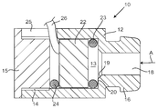
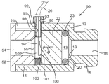
도 1은 본 발명의 이어폰을 통한 길이방향 단면도이다.
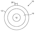
도 2는 도 1의 화살표 A 방향으로의 이어폰의 단부도를 도시한다.
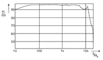
도 3은 도 1의 이어폰에 대한 주파수에 따른 음압 레벨의 변화의 실험적 측정치의 그래프 표현을 도시한다.
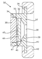
도 4는 본 발명의 헤드폰을 통한 길이방향 단면도이다.
도 5는 본 발명의 대안 이어폰을 통한 길이방향 단면도.
도 6은 본 발명의 대안 헤드폰을 통한 길이방향 단면도이다.
도 7은 이어폰용 케이싱을 변형한 길이방향 단면도이다.
도 8은 이어폰용 케이싱의 변형 예를 도시하는 길이방향 단면도이다.
도 9는 도 5의 이어폰을 변형한 단면도이다.
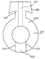
도 10은 케이블 가이드만을 도시하는 도 9의 화살표 B 방향의 도면을 도시한다.1 is a longitudinal sectional view through an earphone of the present invention.
Fig. 2 shows an end view of the earphone in the direction of arrow A in Fig.
Figure 3 shows a graphical representation of an empirical measure of the change in sound pressure level with respect to frequency for the earphone of Figure 1;
4 is a longitudinal sectional view through the headphone of the present invention.
5 is a longitudinal section through an alternative earphone of the present invention.
6 is a longitudinal cross-sectional view through an alternative headphone of the present invention.
Fig. 7 is a longitudinal sectional view of a modified earphone casing. Fig.
8 is a longitudinal sectional view showing a modified example of the earphone casing.
Fig. 9 is a sectional view of the earphone of Fig. 5 modified. Fig.
Fig. 10 shows a view in the direction of arrow B in Fig. 9 showing only the cable guide.
도 1을 참조하면, 이어폰(10)은 내경 5.1 mm의 내부 원통형 챔버(13)를 형성하는 외경 7.0 mm의 일반적으로 원통형 티타늄 케이싱(12)을 포함한다. 일 단부에서, 케이싱(12)은 내부 나사 부분(14)을 형성하고, 나사 플러그(15)는 이 나사 부분(14)과 맞물려 챔버(13)의 단부를 차단한다. 다른 단부에서, 케이싱(12)은 보다 작은 외경의 돌출 부분(16)을 형성하고, 이 돌출 부분(16)은 내부 원통형 챔버(13)와 짧은 테이퍼형 부분(19)을 통해 교통하는 내경 2.2 mm의 축방향 보어(18)를 형성하여, 챔버(13)의 단부에 내부 단차부(20)가 있다.Referring to FIG. 1,
원통형 챔버(13) 내에는, 2 개의 O-링들(23, 24) 사이에 체결된 음향 드라이버(22)가 있으며, 하나의 O-링(23)은 드라이버(22)의 전면과 내부 단차부(20) 사이에 있고, 다른 O-링(24)은 드라이버(22)의 후면과 나사 플러그(15) 사이에 있다. 각각의 O-링들(23, 24)은 1 mm 두께이고 직경 3 mm의 중심 개구를 형성한다. 이 예에서, 나사 부분(14)의 길이를 따라 케이싱 벽을 관통하는 슬롯(25)이 있으며, 드라이버(22)에 연결된 전기 케이블(26)은 O-링(24)에서 절단된 대응 갭을 통해 그리고 슬롯(25)의 단부를 통해서 돌출한다. 변형 예에서, 슬롯(25)은 제공되지 않을 수 있고, 대신에 전기 케이블은 나사 플러그(15)의 중심에 있는 구멍을 통과할 수 있다.Within the
음향 드라이버(22)는 다이애프램(미도시)을 포함하고, 동적 드라이버, 즉 다이애프램이 영구 자석의 필드 내의 보이스 코일(voice coil)에 의해 이동된다. 다이애프램은 드라이버(22)의 전면 인근에 있고, 천공된 금속 커버로 보호되어 있다. 그러한 드라이버는 공지되어 있으며, 예를 들어, 그러한 드라이버는 Shenzhen BTX Electronics Co Ltd에 의해 제조된다. 이 경우 다이애프램은 4.47 mm의 직경을 갖는다. 드라이버(22)는 또한 다이애프램의 후방 주위에 보호 커버를 포함하고, 보호 커버는 적어도 하나의 천공을 포함한다. 드라이버는 상이한 타입, 예를 들어 평형 아마추어 타입, 평면 자기 타입 또는 정전기 타입일 수 있고; 그리고 드라이버의 크기와 다이애프램의 크기가 여기에 설명된 것과 다를 수 있다는 것을 이해할 것이다. The
따라서, O-링(23)을 원통형 챔버(13)에 삽입하고, 그 다음 슬롯(25)을 통해 돌출된 전기 케이블(26)과 함께 드라이버(22)를 삽입함으로써 이어폰(10)을 조립할 수 있다는 것을 이해할 수 있다. O-링(23)은 드라이버의 천공된 금속 커버의 임의의 천공을 폐색하지 않는다. 그 다음, O-링(24)은 제위치에 놓여지고, 전기 케이블(26)이 O-링(24)에서 잘려진 대응 크기의 갭을 통과하고, 나사 플러그(15)는 그 후 제위치에 단단히 나사체결된다. 드라이버(22)는 2 개의 압축된 O-링들(23, 24) 사이에 단단히 견고하게 유지된다. 드라이버(22) 뒤의, 즉 드라이버(22)와 나사 플러그(15) 사이의 원통형 챔버(13)의 부분은 O-링(24)과 케이블(26)의 압축에 의해서 기밀 상태로 유지된다. 따라서, 상기 기밀 공간의 깊이는 단지 압축 O-링(24)의 두께일 뿐이며, 이 경우에는 1.0mm이고, 상기 기밀 공간의 직경은 대략 O-링(24)의 내경이고, 이는 3mm이다.It is thus possible to assemble the
이어폰(10)의 사용시, 돌출 부분(16)은 발포 이어버드(earbud), 예를 들어 메모리 발포 이어버드(미도시)와 함께 제공되고, 사용자의 외이도에 삽입되어, 축방향 보어(18)가 사용자의 외이도에 직접 연결된다. 드라이버(22)의 전면으로부터 나오는 소리는 O-링(23)의 내경에 의해 형성된 공간을 통과한 후, 짧은 테이퍼형 부분(19)을 통해서 다른 단부의 사용자의 귀에 결합된 축방향 보어(18) 안으로 들어간다. 축방향 보어(18)는 분명히 이어폰(10)으로부터 나오는 소리가 뒤 따르는 경로의 최협소 부분이며, 따라서 제한적 덕트 부분으로서 작용한다. 축방향 보어(18)의 제공에 의한 이러한 제한적 덕트 부분의 제공은 20Hz와 20kHz 사이의 전체 가청 범위에 걸쳐 선형적으로 작동할 수 있기 때문에, 드라이버(22)의 크게 개선된 주파수 응답을 달성하는 것으로 밝혀졌다.In use of the
도 3을 참조하면, 이것은 상술한 이어폰(10)을 사용하여, 주파수 f(옥타브의 1/48로 평활화 됨)를 갖는 데시벨에서, 음압 레벨 P의 변화에 대한 실험적 시험 데이터를 그래픽으로 도시한다. 이러한 측정은 이어폰(10)을 마이크로폰에 직접 밀봉함으로써 수행되었다. 시험 설비는 16 kHz 이상에서는 만족스런 측정을 하지 못하고, 더 정확한 측정은 시험 헤드를 사용하여 얻을 수 있다. 그럼에도 불구하고, 그래프로부터 음압 레벨 P는 넓은 범위의 가청 주파수 f에 대해 실질적으로 일정하다는 것이 명백하다.Referring to FIG. 3, this graphically illustrates experimental test data for a change in sound pressure level P, in decibels with frequency f (smoothed to 1/48 of an octave) using the
이어폰(10)은 파형 왜곡없이 전체 가청 주파수 범위에 걸쳐 선형 응답을 제공할 수 있다는 것이 밝혀졌다. 소리가 더 정확하게 생성될 뿐만 아니라, 이어폰(10)은 장시간의 착용에 대해 더 편안하고, 사용자는 하루 종일 이어폰(10)을 청취한 후에도 귀가 기분이 상쾌하다고 느끼는 것으로 밝혀졌다.It has been found that the
또한, 본 발명은 헤드폰에도 동일하게 적용될 수 있다는 것을 이해할 것이다. 이 경우, 드라이버와 케이싱은 전형적으로 상당히 크며, 예를 들어 드라이버는 직경이 25mm, 35mm 또는 50mm이고, 케이싱은 일반적으로 3 내지 6mm의 더 큰 직경이다. 상술한 바와 같이, 케이싱은 축방향 보어(18)와 동등한 제한적 덕트 부분을 형성해야 하고, 그 단면적은 다이애프램의 단면적의 19% 내지 30% 사이이다. 특정 드라이버 및 다이애프램의 경우, 제한적 덕트 부분의 최적 크기는 실험에 의해 발견될 수 있지만, 전형적으로 다이애프램의 단면적의 20% 내지 28%이므로, 통상적으로 다이애프램 직경의 0.45 내지 0.53 배이다. 예를 들어, 직경 33mm의 다이애프램을 갖는 직경 35mm의 드라이버의 경우, 전형적으로 제한적 덕트 부분은 14.8mm 내지 17.5mm 의 직경을 갖는다.It will also be appreciated that the present invention is equally applicable to headphones. In this case, the driver and casing are typically quite large, e.g. the driver is 25 mm, 35 mm or 50 mm in diameter, and the casing is usually a larger diameter of 3 to 6 mm. As described above, the casing must form a limited duct portion equivalent to the
이제 도 4를 참조하면, 그러한 헤드폰(30)이 단면도로 도시되어 있다. 헤드폰(30)은 내경 40.5mm의 내부 원통형 챔버(33)를 형성하는 외경 50mm의 일반적으로 원통형인 알루미늄 케이싱(32)을 포함한다. 일 단부에서 케이싱(32)은 내부 나사 부분(34)을 형성하고, 나사 플러그(35)는 내부 나사 부분(34)과 맞물리고 챔버(33)의 단부를 차단한다. 다른 단부에서, 케이싱(32)은 외부 플랜지(36) 및 내경 17.0mm의 원통형 개구(38)를 형성하는 내부 플랜지(37)를 형성한다. 내부 플랜지(38)의 내부면은 테이퍼형 부분(39)을 가지며, 또한 챔버(33)의 단부에 내부 단차부(40)를 형성한다. 부드러운 탄성 물질의 링 형상의 귀 쿠션(42)이 외부 플랜지(36) 상으로 설치되고 헤드폰(30)의 사용시에 사용자의 머리 측에 대면한다.Referring now to Figure 4, such a
원통형 챔버(33) 내에는, 외경이 40mm 인 대체로 평평한 원통형이지만 그 후면으로부터 돌출하는 원통형 자석(45)을 포함하는 음향 드라이버(44)가 있다. O-링(46)은 드라이버(44)의 전면과 내부 단차부(40) 사이에서 압축되는 반면, 나사 플러그(35)는 원통형 자석(45)에 대해 가압된다. O-링(46)은 두께가 1 mm이고 외경이 40 mm이므로, 드라이버(44)의 전면 주변부에 인접한다. 이 예에서는 케이싱 벽을 관통하는 구멍(47)이 있고, 드라이버(44)에 전기적으로 연결하기 위해 전기 케이블(미도시)이 통과할 수 있는 드라이버(44)의 후면 뒤의 원통형 챔버(33)와 교통한다.Within the
O-링(46)은 별개의 구성요소로서 도시되어 있지만, 대안적으로 음향 드라이버(44)의 전면에 돌출 림을 형성할 수도 있다. 음향 드라이버(44)는 다이애프램(미도시)을 포함하고, 동적 드라이버이며, 말하자면, 다이애프램은 자석(45)의 필드에서 보이스 코일에 의해 이동된다. 다이애프램은 천공된 금속 커버에 의해 보호되는 드라이버(44)의 전면 인근에 있다. 이 경우 다이애프램의 직경은 35mm이다. 드라이버(44)는 또한 다이애프램의 후방 주위에 보호 커버를 포함하고, 보호 커버는 적어도 하나의 천공을 포함한다. 드라이버는 다른 유형, 예를 들어 평형 아마추어 유형, 평면 자기 유형 또는 정전기 유형일 수 있고, 드라이버의 크기와 다이애프램의 크기가 여기에 설명된 것과 다를 수 있다는 것을 이해할 것이다. Although the O-
헤드폰(30)은 개별 구성요소들일 경우에는 O-링(46)을 원통형 챔버(33) 안으로 삽입하고, 그 다음 드라이버(44)를 삽입하고, 그 다음 그 구멍(47)에 전기 케이블을 삽입하여 전기 케이블을 드라이버(44)와 연결함으로써 조립될 수 있다. O-링(46)은 드라이버의 천공된 금속 커버의 임의의 천공들에 의해서 폐색되지 않는다. 나사 플러그(35)가 삽입되고 조여진다. 드라이버(44) 뒤의, 즉 드라이버(44)와 나사 플러그(35) 사이의 원통형 챔버(33)의 부분은 O-링(46)의 압축에 의해 기밀하게 된다.이 기밀 공간의 깊이는 이 경우 폭이 2 mm 인 자석(45)의 돌출 부분의 두께이다.The
헤드폰(30)의 사용시에, 귀 쿠션(42)은 소리의 누설을 억제하여, 사용자의 귀에 소리가 제공된다. 드라이버(44)의 전면으로부터 나오는 소리는 내부 플랜지(37)의 테이퍼형 부분(39)에 의해 형성된 테이퍼링 공간을 통과한 후, 원통형 개구(38)을 통과해야 한다. 이 원통형 개구(38)는 명확하게 헤드폰(30)으로부터 나오는 소리가 따르는 경로의 최협소 부분이고 따라서 제한적 덕트 부분으로서 작용하여 가청 주파수 범위에 대해 보다 균일하고 일관된 소리 출력의 상술한 동일 이점을 제공한다. 이러한 개선은 전방의 제한적 덕트 부분(38) 및 드라이버(44)의 후방의 기밀 캐비티의 결과로서 발생하는 다이애프램의 전방 및 다이애프램 뒤의 캐비티에서의 압력 변화가 서로 상쇄되기 때문에 발생하는 것으로 추정된다.In use of the
헤드폰(30)에 대한 변형 예에서, 자석(45)은 플러그(35)와 접촉하지 않고 대신에 드라이버(44)의 후면과 그 주변 인근의 플러그(35)의 면 사이에 압축된 O-링 이 있고, 상기 O-링은 케이블의 통과를 위해 구멍(47)과 정렬된 노치 또는 갭을 형성한다.In a variation on the
상술한 실시예는 기밀 상태의 후방 캐비티를 포함한다. 다른 실시예는 후방 캐비티와 교통하는 축방향 후방 출구 덕트를 형성하며, 이하에서 설명된다. 상기 특징들의 대부분은 상기 기술된 것과 동일하며, 동일한 참조 번호로 참조된다.The above-described embodiment includes a rear cavity in an airtight state. Another embodiment forms an axial rear exit duct that communicates with the rear cavity, and is described below. Most of the above features are the same as those described above, and are referred to by the same reference numerals.
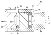
도 5를 참조하면, 이어폰(50)은 내경 5.1 mm의 내부 원통형 챔버(13)를 형성하는 외경 7.0 mm의 일반적인 원통형 티타늄 케이싱(12)을 포함한다. 일 단부에서, 케이싱(12)은 내부 나사 부분(14)을 형성하고, 나사 플러그(52)는 이 나사 부분(14)과 맞물린다. 나사 플러그(52)는 짧은 테이퍼형 부분(55)을 통해 내부 원통형 챔버(13)와 교통하는 내경 2.2 mm의 축방향 보어(54)를 형성한다. 다른 단부에서, 케이싱(11)은 더 작은 외경의 돌출 부분(16)을 형성하고, 이 돌출 부분(16)은 짧은 테이퍼형 부분(19)을 통해 내부 원통형 챔버(13)와 교통하는 내경 2.2 mm의 축방향 보어(18)를 형성한다. 각각의 짧은 테이퍼형 부분(55, 19)의 최광폭 단부는 2.6㎜이다. 따라서, 챔버(12)의 전단부에는 내부 단차부(20)가 있다. 화살표(A)의 방향에서의 이어폰(50)의 모습은 도 2에 도시된 것과 동일하다는 것을 이해할 수 있을 것이다.Referring to Fig. 5,
원통형 챔버(13) 내에는, O-링들(23, 24) 사이에서 체결되는 음향 드라이버(22)가 있고, 한 O-링(23)은 드라이버(22)의 전면과 내부 단차부(24) 사이에 있고, 다른 O-링(24)은 짧은 테이퍼형 부분(55)을 둘러싸는 나사 플러그(52)의 면과 드라이버(22)의 후면 사이에 있다. 각각의 O-링들(23, 24)은 1 mm의 두께를 가지며 직경 3 mm의 중심 개구를 형성한다. 상기 나사 부분(14)의 길이를 따라 케이싱 벽을 관통하는 슬롯(25)이 있고, 상기 드라이버(22)에 연결된 전기 케이블(26)은 O-링(24)에서 절단된 대응하는 갭을 통해 그리고 슬롯(25)의 단부를 통해 돌출한다.Within the
음향 드라이버(22)는 다이애프램(미도시)을 포함하고, 동적 드라이버, 즉 다이애프램이 영구 자석의 필드 내의 보이스 코일에 의해 이동된다. 다이애프램은 드라이버(22)의 전면 인근에 있고 천공된 금속 커버로 보호되어 있다. 이 경우 다이애프램의 직경은 4.47mm이다. 드라이버(22)는 또한 다이애프램의 후방 주위에 보호 커버를 포함하고, 보호 커버는 적어도 하나의 천공을 포함한다. 드라이버는 상이한 타입, 예를 들어 평형 아마추어 타입, 평면 자기 타입 또는 정전기 타입일 수 있고 드라이버의 크기와 다이애프램의 크기가 여기에 설명된 것과 다를 수 있다는 것을 이해할 수 있다. The
따라서, O-링(23)을 원통형 챔버(13)에 삽입한 후, 전기 케이블(26)을 슬롯(25)을 통해 돌출시켜 드라이버(22)를 삽입함으로써 이어폰(50)을 조립할 수 있다는 것을 이해할 수 있다. O-링(23)은 드라이버의 천공된 금속 커버의 임의의 천공을 폐색하지 않는다. O-링(24)은 그 다음, 제위치에 놓이고, 전기 케이블(26)이 O-링(24)에서 절단된 대응 크기의 갭을 통과하고, 나사 플러그(52)는 그 후 제위치에 단단히 나사체결된다. 드라이버(22)는 2 개의 압축된 O-링들(23, 24) 사이에 단단히 견고하게 유지된다. 드라이버(22) 뒤의, 즉 드라이버(22)와 나사 플러그(52) 사이의 원통형 챔버(13) 부분의 임의의 압력 변동 또는 음파는 축방향 보어(54)를 통해 전파될 수 있고; 유사하게 드라이버(22)의 전방에 있는 원통형 챔버(13)의 부분에서 드라이버(22)에 의해 생성된 음파가 축방향 보어(18)를 통해 사용자의 귀에 전파된다.It is therefore understood that the
O-링(23) 및 O-링(24)은 (도시된 바와 같은 축방향 단면에서) 비원형 단면 형상을 가질 수 있음을 이해할 것이다. 예를 들어, 와셔 또는 가스켓의 반경 방향의 폭이 드라이버(22)의 면의 상당한 부분을 차단하게 매우 크지 않다면, 이들은 네오프렌 고무 와셔 또는 가스켓으로 대체될 수 있으며, 이 경우 각 측부의 단면 형상은 정사각형 또는 직사각형이다. 성형된 실리콘과 같은 다른 물질도 적합하다.It will be appreciated that O-
이어폰(50)을 사용할 때, 돌출 부분(16)은 발포 이어버드, 예를 들어 메모리 폼 이어버드(미도시)를 구비하고, 사용자의 외이도에 삽입되어, 축방향 보어(18)는 사용자의 외이도에 직접 연결된다. 드라이버(22)의 전면으로부터 나오는 소리는 O-링(23)의 내경에 의해 형성된 공간을 통과한 후, 짧은 테이퍼형 부분(19)을 통해 축방향 보어(18)로 전달되고, 상기 축방향 보어(18)는 다른 단부에서 사용자의 귀에 결합된다. 축방향 보어(18)는 분명히 이어폰(50)으로부터 나오는 소리가 뒤 따르는 경로의 최협소 부분이며, 따라서 제한적 덕트 부분으로서 작용한다. 유사하게, 축방향 보어(54)는 드라이버(22)의 후방으로부터 전파되는 임의의 소리에 대한 경로의 최협소 부분이고, 따라서 제한적 덕트 부분으로서 작용한다. 축방향 보어(54, 18)는 모두 원통형 챔버(13)와 동축이고 동일한 직경을 갖기 때문에 서로 정렬된다. 동일한 직경의 2 개의 축방향으로 정렬된 제한적 덕트 부분의 제공은 20Hz 내지 20kHz의 전체 가청 범위에 걸쳐 선형적으로 작동할 수 있기 때문에, 드라이버(22)의 개선된 주파수 응답을 달성하는 것으로 밝혀졌다.When using the
상술한 이어폰들(10 및 50)은 다양한 방식들로 수정될 수 있음을 이해할 것이다. 예를 들어, 케이싱(12)은 알루미늄과 같은 상이한 물질 또는 엔지니어링 플라스틱과 같은 강성 비금속 물질로 이루어질 수 있다. 치수는 또한 예로서만 제공된다. 테이퍼형 부분(19)의 경사 및 길이는 도시된 것과 다를 수 있고; 단차부(20)는 상이한 크기, 예를 들어 O-링(23)의 두께보다 크지 않을 수 있다. 분명히 내부 원통형 챔버(13)의 직경은 드라이버(22)의 크기에 꼭 맞아야만해서, 챔버의 내경도 더 큰 드라이버에 상응하여 더 클 것이다.It will be appreciated that the
또한, 상술한 이어폰(10 또는 50)에서, O-링들(23, 24)의 두께는 드라이버(22)의 면과 내부 챔버(13)의 대응 단부면 사이의 거리를 결정한다는 것을 이해할 수 있다. 드라이버(22)의 면과 내부 챔버(13)의 단부면 사이에 큰 거리가 필요한 경우, 이것은 더 두꺼운 O-링을 사용하거나 또는 O-링들(23, 24)을 다른 링 형상의 항목, 예를 들어 두 번째 O-링 또는 강성 물질의 링과 조합함으로써 달성될 수 있다. 각각의 경우에, 각 O-링은 고무 와셔 또는 가스켓으로 교체될 수 있다.It will also be appreciated that in the
이어폰(50)은 파형 왜곡없이 전체 가청 주파수 범위에 걸쳐 선형 응답을 제공할 수 있다는 것이 밝혀졌다. 소리가 더 정확하게 생성될뿐만 아니라, 이어폰(50)은 장기간의 착용에 더욱 편안할 수 있고 하루 종일 이어폰을 청취한 후에도 사용자는 신선함을 느끼고; 사용자는 하루 종일 사용하는 경우에도 귀의 피로를 덜보고한 것으로 확인되었다. It has been found that the
또한, 본 발명은 헤드폰에도 동일하게 적용될 수 있다는 것을 이해할 것이다. 이 경우, 드라이버와 케이싱은 전형적으로 상당히 크며, 예를 들어 드라이버는 직경이 25mm, 35mm 또는 50mm이고, 케이싱은 보다 큰 직경, 전형적으로 3 내지 6mm 더 크다. 상술한 바와 같이, 케이싱은 축방향 보어(54)와 동등한 제한적 덕트 부분 및 축방향 보어(18)와 동등한 정렬된 제한적 덕트 부분을 형성해야 한다.It will also be appreciated that the present invention is equally applicable to headphones. In this case, the driver and casing are typically quite large, e.g. the driver is 25 mm, 35 mm or 50 mm in diameter and the casing is of larger diameter, typically 3 to 6 mm larger. As described above, the casing must form a limited duct portion equivalent to the
이제 도 6을 참조하면, 그러한 헤드폰(60)이 단면도로 도시되어 있다. 헤드폰(60)은 내경 40.5mm의 내부 원통형 챔버(33)를 형성하는 외경 50mm의 일반적으로 원통형인 알루미늄 케이싱(32)을 포함한다. 일 단부에서, 케이싱(32)은 내부 나사 부분(34)을 형성하고, 나사 플러그(62)는 상기 나사 부분(34)과 맞물린다. 다른 단부에서, 케이싱(32)은 외부 플랜지(36) 및 내부 플랜지(37)를 형성한다. 내부 플랜지(37)의 내부면은 테이퍼링 덕트 부분(39)을 형성하도록 테이퍼지고, 또한 챔버(33)의 단부에 내부 단차부(40)를 형성한다. 테이퍼링 덕트 부분(39)은 내경 17.0㎜의 원통형 개구 또는 보어(38)와 교통한다. 부드러운 탄성 물질의 링 형상의 귀 쿠션(42)은 외부 플랜지(36) 상에 장착되고, 헤드폰(60)의 사용시 사용자의 머리의 측부에 대항한다. 원통형 개구 또는 보어(38)는 내부 원통형 챔버(33)와 동축방향이다. Referring now to Figure 6, such a
나사 플러그(62)는 원통형 챔버(33) 안으로 이어지는 테이퍼형 부분(65)과 교통하는 내경 17.0mm의 원통형 개구 또는 보어(64)를 형성하고, 나사 플러그(62)에 이웃하는 테이퍼형 부분(65)의 개방 단부를 둘러싸는 환형면(66)이 있다. 테이퍼형 부분(65)은 테이퍼링 덕트 부분(39)과 동일한 치수를 가지며; 원통형 개구 또는 보어(64)는 원통형 개구(38)와 정렬된다.The threaded
원통형 챔버(33) 내에는, 외경이 40mm 인 대체로 평평한 원통형이지만 그 후면으로부터 돌출하는 원통형 자석(45)을 포함하는 음향 드라이버(44)가 있다. 외경이 40 mm 인 금속 링(67)은 음향 드라이버(44) 뒤에 위치하고, 드라이버(44)의 후면과 나사 플러그(62)의 환형면(66) 사이에서 O-링(68)이 압축된다. 유사하게, O-링(46)은 드라이버(44)의 전면과 내부 단차부(40) 사이에서 압축된다. O-링(46, 68)은 두께가 각각 1 mm이고 외경이 40 mm이므로, 이들은 원통형 챔버(33)의 주변부에 인접하다. 이 예에서, 케이싱 벽을 관통하여 드라이버(44)의 후면 뒤의 원통형 챔버(33)와 교통하는 구멍(47)이 있고, 전기 케이블(미도시)이 드라이버(44)와 전기적으로 연결하기 위해 상기 구멍을 통과할 수 있다. Within the
O-링(46)은 별도의 구성요소로서 도시되어 있지만, 이는 대안적으로 음향 드라이버(44)의 전면에 돌출 림을 형성할 수도 있다. 유사하게, O-링(68)은 별개의 구성요소로서 도시되어 있지만, 대안적으로 금속 링(67)의 면 상에 돌출된 탄성 림을 형성할 수도 있다. 음향 드라이버(44)는 다이애프램(미도시)을 포함하고, 동적 드라이버 즉 다이애프램은 자석(45)의 필드에서 보이스 코일에 의해 이동된다. 다이애프램은 천공된 금속 커버에 의해 보호되는 드라이버(44)의 전면 인근에 있다. 이 경우 다이애프램의 직경은 35mm이다. 드라이버(44)는 또한 다이애프램의 후방 주위에 보호 커버를 포함하고, 보호 커버는 적어도 하나의 천공을 포함한다. 드라이버는 다른 유형, 예를 들어 평형 아마추어 유형, 평면 자기 유형 또는 정전기 유형일 수 있고; 드라이버의 크기와 다이애프램의 크기가 여기에 설명된 것과 다를 수 있다.Although the O-
헤드폰(60)은 O-링이 별도의 구성요소이라면, O-링(46)을 원통형 챔버(33)에 삽입한 다음 드라이버(44)를 삽입하고, 그 후에 전기 케이블을 구멍(47)에 삽입하고 전기 케이블을 드라이버(44)에 연결함으로써 조립될 수 있다. O-링(46)은 드라이버의 천공된 금속 커버의 임의의 천공들을 폐색하지 않는다. 금속 링(67)과 O-링(68)이 삽입되고, 금속 링(67)은 전기 케이블이 통과하는 홈(미도시)을 형성한다. 나사 플러그(62)는 그 다음 O-링(46, 68)이 압축되도록 삽입되고 조여진다.The
헤드폰(60)의 사용시에, 상기 귀 쿠션(42)은 소리의 누출을 억제하여, 상기 소리는 사용자의 귀에 제공된다. 드라이버(44)의 전면으로부터 나온 소리는 테이퍼링 덕트 부분(39)을 통과한 후에 원통형 개구 또는 보어(38)를 통과해야 한다. 유사하게, 원통형 개구(38, 64)는 확실히 드라이버(44)의 후면으로부터 나오는 소리가 따르는 경로의 최협소 부분들이고 제한적 덕트 부분으로서 작용하여 상술한 것과 동일한 이점 즉, 가청 주파수 범위에 걸쳐 보다 균일하고 일관된 소리 출력의 이점을 제공한다.In use of the
원통형 챔버(33)의 단부에서 내부 단차부(40) 및 드라이버(44)의 전면 사이의 거리는 O-링(46)의 두께에 의해 결정된다는 것을 이해할 수 있을 것이다. 드라이버(44) 및 나사 플러그(62) 상의 환형면(66) 사이의 거리는 금속 링(67)과 O-링(68)의 조합의 두께에 의해 결정되기 때문에 약간 더 크다. 하나의 변형 예에서 금속 링(67)은 생략되어서, 드라이버(44)의 주변부의 후면과 나사 플러그(62) 사이의 거리를 감소시키고; 본 변형 예에서, 원통형 자석(45)은 테이퍼형 부분(65) 내로 약간 돌출될 것이다. 다른 변형 예에서, 제 2 링(67)은 O-링(46)에 인접하여 삽입될 수 있으므로, 드라이버(44)의 전면과 원통형 챔버(33)의 단부 사이의 거리를 증가시킨다. 상술한 이어폰(10,50)에서, O-링(46 및 68)은 고무 가스켓 또는 와셔로 교체될 수 있다. 실제로, O-링이 기술되는 각각의 경우에, 고무 가스켓 또는 와셔, 예를 들어 일반적으로 0.3mm 내지 5 mm, 예를 들어 0.5 mm의, 성형된 실리콘과 같은 고무 대체 물질의 평평한 와셔 또는 가스켓으로 교체될 수 있다. It will be appreciated that the distance between the
이어폰(50) 및 헤드폰(60) 둘 모두에서, 드라이버와 동축인 동일한 직경의 2 개의 정렬된 출구, 즉 이어폰(50)의 축방향 보어(54 및 18) 및 헤드폰(60)의 원통형 개구(64 및 38)의 제공에 의해 음질이 향상된다는 것이 밝혀졌다. 반대로, 예를 들어 후방 출구[즉, 축방향 보어(54) 또는 원통형 개구(64))]가 원통형 챔버(13 또는 33)와 동축이 아닌 경우, 이는 훨씬 낮은 음질을 생성한다. 비축방향 출구가 드라이버에게 비대칭 압력 분포를 유발하여 음질에 해로운 것으로 추측된다.In both the
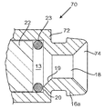
이어폰(10, 50)에서, 돌출 부분(16)은 축방향 보어(18)에 이르는 짧은 테이퍼형 부분(19)을 갖는 소리 출구 덕트를 형성한다. 보어(18)의 길이방향 축에 대한 테이퍼 각도는 양호하게는 40° 내지 50°이고 두 경우 모두 45°이다. 이제 도 7을 참조하면, 이것은 다시 비록 테이퍼 각도가 45°이지만, 짧은 테이퍼형 부분(19)이 상술한 것보다 상당히 긴 수정된 돌출 부분(16a)을 갖는 케이싱(12)과 상이한, 이어폰(70)용 케이싱(72)의 부분도이다. 돌출 부분(16a)의 외측 단부에서, 축방향 보어(18)는 또한 축에 대해 45° 각도로 선형 테이퍼를 갖는 확장 부분(74) 내로 개방되며; 결과적으로 축방향 보어(18)는 대응하여 더 짧아진다.In the
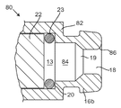
소리 출구 덕트는 양호하게는 테이퍼형 부분을 포함하지만, 이것은 이어폰(80)용 케이싱(82)의 부분도를 도시할 수 있으며, 원통형 부분(84)이 있는 변형된 돌출 부분(16b)을 갖는 케이싱(12)에서만 단지 상이하고, 축방향 보어(18)에 이르는 짧은 테이퍼형 부분(19)이 따르며; 그리고 외부 단부에서 축방향 보어(18)는 짧은 길이방향으로 만곡된 플레어 부분(86)과 교통한다. 테이퍼형 부분(19)은 축에 대하여 45°의 각도에서 선형 테이퍼를 갖는다. 소리 출구 덕트의 이러한 형상은 이어폰(50)에 도시된 바와 같이 플러그(52)의 후방 출구 덕트에 동일하게 적합할 것이다.The sound outlet duct preferably includes a tapered portion but it may show a partial view of the
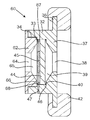
이제 도 9를 참조하면, 대부분의 점에서 도 5의 이어폰(50)과 동일한 이어폰(90)이 도시되며, 동일한 특징은 동일한 참조 번호로 참조된다. 유일한 차이점은 O-링 시일(24)에 케이블(26)을 위한 갭을 제공하는 대신에, 케이블(26)이 나일론으로 형성된 케이블 가이드(92)를 통해 제공된다는 것이다. 명확하게 하기 위해, 케이블(26)은 케이블 가이드(92) 내에 도시되지 않는다.Referring now to FIG. 9, in many respects the
도 9 및 도 10을 참조하면, 케이블 가이드(92)는 드라이버(22) 뒤의 원통형 캐비티(13) 내에 동축방향으로 끼워지고 스터드(95)가 반경방향으로 돌출하는 체결 링(94)을 형성하고, 스터드(95)는 슬롯(25)을 통해 끼워지고 원통형 케이싱(12)의 외면을 향해 끼워지는 큰 부분(96)을 갖는다. 입구 덕트(97)는 스터드(95)의 길이에 걸쳐 그리고 체결 링(94)의 인접한 부분을 통해 연장된다. 입구 덕트(97) 내의 중간 위치에서, 좌측 벽(도 9에 도시됨)은 돌출된 둥근 험프(98)를 형성한다. 따라서, 케이블(26)은 입구 덕트(97)를 통해 그리고 링(94)의 중간부를 통해 연장되어 드라이버(22)의 후방에 도달할 수 있고, 둥근 험프(98)와의 마찰에 의해서 체결된다.9 and 10, the
케이블 가이드(92)는 두 개의 정합 부분, 즉 입구 덕트(97)의 일 측부(도 9에 도시된 바와 같이 우측)를 형성하고 체결 링(94)의 일면의 아치형 부분을 형성하지만, 아치형 부분의 단부들(101; 이들중 하나만 도 9에 도시됨) 사이의 원주방향 갭을 형성하는 제 1 부분(100); 및 입구 덕트(97)의 다른 측부를 형성하고, 또한 단부(101)들 사이의 원주방향 갭에 끼워지는 돌출 부분(103)을 포함하는 체결 링(94)의 나머지를 형성하는 제 2 부분(102)을 포함한다. 2 개의 부분(100, 102)이 함께 조립될 때, 체결 링(94)은 실질적으로 연속 전면 및 실질적으로 연속 후면을 갖는다.The
따라서, 조립 중에 케이블(26)의 와이어는 드라이버(22)의 후방 단자에 납땜될 수 있다. 그 다음, 케이블(26)은 아치형 부분의 2개의 단부들(101)이 케이블(26)의 반대 측부들에서 돌출하도록, 그 다음 케이블 가이드(92)의 제 1 부분(100)에 의해서 형성되는 입구 덕트(97)의 우측 측부(도 9에 도시됨)에 놓여진다. 케이블 가이드(92)의 제 2 부분(102)은 그 다음 제 1 부분(100)과 함께 조립되어, 돌출 부분(103)은 아치형 부분의 2 개의 단부들(101) 사이에 끼워져 체결 링(94)의 우측부(도 9에 도시됨)를 완성하고 케이블(26)은 그 다음 돌출 험프(98)에 의해 압착되어 체결된다. 나사 플러그(52)는 나사 부분(14) 내로 나사 결합되어 체결 링(94)이 플러그(52)의 전면과 드라이버(22)의 후면 사이에서 압축된다. 체결 링(94)은 드라이버(22)의 후면의 전체 주변부 주위에 실질적으로 균일한 압축을 제공한다.Thus, the wire of
또한, 케이블(26)은 입구 덕트(97) 내의 험프(98)에 의해 체결되어 케이블(26)의 장력이 케이블 가이드(92)를 통해 이어폰(90)으로 전달되므로 케이블(26)의 와이어와 드라이버(22)의 단자 사이의 연결부 또는 납땜 결합부는 장력을 받지 않는다. The
Claims (14)
상기 케이싱은 드라이버를 위치시키기 위한 캐비티를 형성하고 또한 사용자의 귀에 소리를 제공하도록 상기 캐비티의 전방 단부와 교통하는 소리 출구 덕트를 형성하며, 상기 케이싱에는 후방 폐쇄 요소가 제공되고, 상기 케이싱은 상기 드라이버의 전면에서 다이애프램에 의해서 드라이버를 봉입하여, 상기 드라이버가 드라이버-위치설정 캐비티를 상기 드라이버 뒤의 후방 캐비티와 상기 드라이버의 전방에 있고 상기 소리 출구 덕트와 교통하는 전방 캐비티로 분할하고; 그리고 또한 적어도 하나의 탄성 요소를 포함해서, 상기 드라이버가 주변부 인근의 그 전면과 결합하는 탄성 요소 및 후면과 결합하는 후방 요소 사이에서 체결되고, 상기 전면과 결합하는 상기 탄성 요소는 상기 전방 캐비티의 단부면 및 상기 드라이버의 전면 사이에서 압축되는, 헤드폰 또는 이어폰.A headphone or earphone comprising a casing suitable for being fitted to a user's ear,
The casing forming a cavity for positioning the driver and also forming a sound outlet duct communicating with the front end of the cavity to provide sound to the user's ear, the casing being provided with a rear closing element, Wherein the driver divides the driver-positioning cavity into a rear cavity behind the driver and a front cavity in front of the driver and in communication with the sound outlet duct; And at least one elastic element, the driver being fastened between an elastic element engaging the front surface of the periphery thereof and a rear element engaging the rear surface, wherein the elastic element engaging the front surface engages the end of the front cavity And is compressed between the front face of the driver and the front face of the driver.
상기 후방 요소는 또한 탄성 요소이고, 그 주변부 인근에 있는 상기 드라이버의 후면과 결합하는, 헤드폰 또는 이어폰.The method according to claim 1,
Wherein the rear element is also an elastic element and engages with a rear surface of the driver near its periphery.
상기 탄성 요소는 O-링 시일들 또는 가스켓들인, 헤드폰 또는 이어폰.3. The method according to claim 1 or 2,
Wherein the elastic element is O-ring seals or gaskets.
상기 후방 폐쇄 요소는 나사형 연결부에 의해서 상기 케이싱에 연결되는, 헤드폰 또는 이어폰.4. The method according to any one of claims 1 to 3,
Wherein the rear closure element is connected to the casing by a threaded connection.
상기 후방 폐쇄 요소는 상기 캐비티의 단부 부분 내에서 적어도 부분적으로 끼워지고, 그리고 상기 나사형 연결부는 상기 캐비티의 단부 부분의 내벽 상의 스크류 나사 부분을 포함하는, 헤드폰 또는 이어폰.5. The method of claim 4,
Wherein the rear closure element is at least partially fitted within the end portion of the cavity and the threaded connection includes a screw threaded portion on the inner wall of the end portion of the cavity.
상기 소리 출구 덕트는 테이퍼형 덕트 부분을 포함하고, 상기 테이퍼형 덕트 부분은 상기 드라이버에 최인접한 단부에서 가장 넓고 상기 제한적 덕트 부분으로 얇게 테이퍼지는, 헤드폰 또는 이어폰.6. The method according to any one of claims 1 to 5,
Wherein the sound outlet duct includes a tapered duct portion and wherein the tapered duct portion is widest at the end closest to the driver and tapers thinly into the limited duct portion.
상기 테이퍼형 덕트 부분은 상기 소리 출구 덕트의 길이방향 축에 대해서 40°내지 50°로 경사진 선형 테이퍼를 갖는, 헤드폰 또는 이어폰.The method according to claim 6,
Said tapered duct portion having a linear taper that is angled from 40 to 50 degrees with respect to a longitudinal axis of said sound outlet duct.
상기 소리 출구 덕트는 상기 다이애프램의 단면적의 19% 내지 30%의 단면적을 갖는 제한적 덕트 부분을 형성하는, 헤드폰 또는 이어폰.8. The method according to any one of claims 1 to 7,
Said sound outlet duct forming a restricted duct portion having a cross-sectional area of 19% to 30% of the cross-sectional area of said diaphragm.
상기 후방 캐비티는 봉입된 기밀 캐비티인, 헤드폰 또는 이어폰.9. The method according to any one of claims 1 to 8,
Wherein the rear cavity is an enclosed airtight cavity.
상기 후방 캐비티는 상기 소리 출구 덕트와 축방향으로 정렬된 후방 출구 덕트를 형성하는, 헤드폰 또는 이어폰.9. The method according to any one of claims 1 to 8,
Said rear cavity forming a rear outlet duct axially aligned with said sound outlet duct.
상기 후방 출구 포트는 상기 소리 출구 덕트의 제한적 덕트 부분과 동일한 단면적의 후방 제한적 덕트 부분을 형성하는, 헤드폰 또는 이어폰.11. The method of claim 10,
The rear outlet port forming a rear limited duct portion of the same cross-sectional area as the limited duct portion of the sound outlet duct.
상기 케이싱은 드라이버와의 연결을 위해 케이블의 진입을 위한 슬롯을 형성하는 벽을 갖는 원통형 캐비티를 형성하고, 또한 케이블 가이드를 포함하며, 상기 케이블 가이드는 상기 슬롯 내에 위치할 수 있는 입구 덕트와, 상기 원통형 캐비티 내에 동축방향으로 끼워지는 체결 링을 형성하고, 상기 케이블 가이드는 2 개의 정합 부분; 즉 상기 입구 덕트의 일 측부를 형성하고, 아치형 부분의 단부들 사이의 원주방향 갭을 형성하기 위해 상기 체결 링의 일 면의 아치형 부분을 형성하는 제 1 부분; 및 상기 입구 덕트의 다른 측부를 형성하고 또한 상기 체결 링의 잔여부를 형성하여, 상기 두 부분들이 함께 놓일 때, 상기 체결 링은 실질적으로 연속 전면 및 실질적으로 연속 후면을 갖는 제 2 부분을 포함하는, 헤드폰 또는 이어폰.12. The method according to any one of claims 1 to 11,
Said casing defining a cylindrical cavity having a wall defining a slot for entry of a cable for connection with a driver and also comprising a cable guide, said cable guide being able to be positioned in said slot, Wherein the cable guide defines a fastening ring coaxially fitted within the cylindrical cavity, the cable guide having two mating portions; A first portion forming one side of the inlet duct and forming an arcuate portion of one side of the clamping ring to form a circumferential gap between the ends of the arcuate portion; And a second portion having a substantially continuous front surface and a substantially continuous rear surface when the two portions are laid together, wherein the fastening ring comprises a first portion and a second portion, Headphones or earphones.
상기 케이블 가이드의 제 2 부분은 상기 체결 링의 후면을 형성하는 링을 형성하고, 상기 케이블 가이드의 제 1 부분의 아치형 부분의 단부들 사이의 원주방향 갭에 끼워지는 아치형 부분이 상기 체결 링의 후면으로부터 돌출하는, 헤드폰 또는 이어폰.13. The method of claim 12,
Wherein a second portion of the cable guide defines a ring defining the rear surface of the locking ring and an arcuate portion that fits in a circumferential gap between the ends of the arcuate portion of the first portion of the cable guide, The headphone or earphone.
Applications Claiming Priority (5)
| Application Number | Priority Date | Filing Date | Title |
|---|---|---|---|
| GB1506111.2 | 2015-04-10 | ||
| GBGB1506111.2A GB201506111D0 (en) | 2015-04-10 | 2015-04-10 | Headphone or earphone |
| GB1518586.1 | 2015-10-20 | ||
| GBGB1518586.1A GB201518586D0 (en) | 2015-10-20 | 2015-10-20 | Headphone or earphone |
| PCT/GB2016/050981 WO2016162681A1 (en) | 2015-04-10 | 2016-04-07 | Headphone or earphone |
Publications (1)
| Publication Number | Publication Date |
|---|---|
| KR20170134703A true KR20170134703A (en) | 2017-12-06 |
Family
ID=55754326
Family Applications (1)
| Application Number | Title | Priority Date | Filing Date |
|---|---|---|---|
| KR1020177032213A KR20170134703A (en) | 2015-04-10 | 2016-04-07 | Headphones or earphones |
Country Status (6)
| Country | Link |
|---|---|
| US (1) | US11343606B2 (en) |
| EP (1) | EP3281415B1 (en) |
| JP (1) | JP2018511273A (en) |
| KR (1) | KR20170134703A (en) |
| CN (1) | CN107873134B (en) |
| WO (1) | WO2016162681A1 (en) |
Families Citing this family (4)
| Publication number | Priority date | Publication date | Assignee | Title |
|---|---|---|---|---|
| GB2559313A (en) * | 2016-11-11 | 2018-08-08 | Flare Audio Tech Limited | Earphone |
| US10491975B2 (en) * | 2017-10-20 | 2019-11-26 | Bose Corporation | Acoustic transducer system |
| EP3742753B1 (en) | 2019-05-24 | 2021-12-01 | Honeywell International Inc. | Hearing protection devices, noise exposure sensors therefor, and sensor housings and associated methods for the same |
| US11245972B2 (en) | 2019-12-06 | 2022-02-08 | Steven Hill | Ear tip device |
Family Cites Families (30)
| Publication number | Priority date | Publication date | Assignee | Title |
|---|---|---|---|---|
| JPS63200988U (en) * | 1987-06-15 | 1988-12-23 | ||
| US5682434A (en) * | 1995-06-07 | 1997-10-28 | Interval Research Corporation | Wearable audio system with enhanced performance |
| JP4151157B2 (en) | 1999-05-31 | 2008-09-17 | ソニー株式会社 | earphone |
| JP2006246426A (en) * | 2005-06-15 | 2006-09-14 | Kazuo Suzuki | Earphone attachment and earphone equipped with the earphone attachment |
| JP4709017B2 (en) * | 2006-01-12 | 2011-06-22 | ソニー株式会社 | Earphone device |
| US8180093B2 (en) * | 2007-01-05 | 2012-05-15 | Apple Inc. | Assembly for coupling the housings of an electronic device |
| US20080166006A1 (en) * | 2007-01-06 | 2008-07-10 | Apple Inc | Light diffuser |
| JP4921197B2 (en) | 2007-02-06 | 2012-04-25 | スター精密株式会社 | Insertion type earphone |
| US8194911B2 (en) | 2007-03-27 | 2012-06-05 | Logitech International, S.A. | Earphone integrated eartip |
| EP2187654B1 (en) | 2007-09-07 | 2014-12-31 | Pioneer Corporation | Earphone |
| CN102006533B (en) | 2009-08-31 | 2014-08-27 | 富准精密工业(深圳)有限公司 | Earphone |
| EP2306755B1 (en) * | 2009-09-03 | 2015-06-03 | AKG Acoustics GmbH | In-ear earphone |
| JP2011082701A (en) * | 2009-10-05 | 2011-04-21 | Foster Electric Co Ltd | Headphone |
| TWI435618B (en) * | 2009-10-05 | 2014-04-21 | Merry Electronics Co Ltd | Earphone device with bass adjustment function |
| JP5666797B2 (en) * | 2009-10-05 | 2015-02-12 | フォスター電機株式会社 | earphone |
| EP2505000A2 (en) | 2009-11-23 | 2012-10-03 | Incus Laboratories Limited | Production of ambient noise-cancelling earphones |
| JP5671929B2 (en) * | 2010-10-12 | 2015-02-18 | ソニー株式会社 | Earphone, acoustic converter |
| CN202035122U (en) * | 2011-01-21 | 2011-11-09 | 东莞达电电子有限公司 | Earphone with live effect |
| US9319767B2 (en) | 2012-01-30 | 2016-04-19 | Panasonic Intellectual Property Management Co., Ltd. | Earphone |
| CN202773055U (en) * | 2012-07-31 | 2013-03-06 | 东莞达电电子有限公司 | Earphone facilitating adjustment of sound effect |
| KR101558091B1 (en) | 2014-05-23 | 2015-10-06 | 부전전자 주식회사 | Canal type earphone with pressure equilibrium means |
| KR101423881B1 (en) * | 2013-05-24 | 2014-07-25 | 부전전자 주식회사 | Micro Speaker Unit for Earphone |
| US8983108B2 (en) | 2013-07-18 | 2015-03-17 | Dexin Corporation | Ear headphone |
| US9363594B2 (en) | 2013-12-13 | 2016-06-07 | Apple Inc. | Earbud with membrane based acoustic mass loading |
| CN203661262U (en) | 2014-01-02 | 2014-06-18 | 东莞市伟旺达电子有限公司 | Dustproof earphone |
| JP3196121U (en) * | 2014-12-10 | 2015-02-19 | 勁剛企業有限公司 | Earphone with vent |
| CN104936080A (en) * | 2015-07-07 | 2015-09-23 | 常州百富电子有限公司 | Earplug with silencing plug post |
| US9794676B2 (en) * | 2016-01-12 | 2017-10-17 | Bose Corporation | Headphone |
| TWI628961B (en) * | 2016-11-24 | 2018-07-01 | 王士俊 | Earphone for regulating pressure in ear canal and providing natural sound and manufacture method thereof |
| CN110944266B (en) * | 2019-12-13 | 2021-07-06 | 多摩电子(东莞)有限公司 | Flexible in-ear type dustproof earphone based on spring is spacing |
-
2016
- 2016-04-07 CN CN201680033719.2A patent/CN107873134B/en active Active
- 2016-04-07 KR KR1020177032213A patent/KR20170134703A/en unknown
- 2016-04-07 US US15/562,368 patent/US11343606B2/en active Active
- 2016-04-07 EP EP16716651.1A patent/EP3281415B1/en active Active
- 2016-04-07 JP JP2017552986A patent/JP2018511273A/en not_active Ceased
- 2016-04-07 WO PCT/GB2016/050981 patent/WO2016162681A1/en active Application Filing
Also Published As
| Publication number | Publication date |
|---|---|
| US20180288520A1 (en) | 2018-10-04 |
| WO2016162681A1 (en) | 2016-10-13 |
| JP2018511273A (en) | 2018-04-19 |
| EP3281415B1 (en) | 2019-06-12 |
| CN107873134B (en) | 2019-08-27 |
| EP3281415A1 (en) | 2018-02-14 |
| US11343606B2 (en) | 2022-05-24 |
| CN107873134A (en) | 2018-04-03 |
Similar Documents
| Publication | Publication Date | Title |
|---|---|---|
| US8238596B2 (en) | In-ear headphones | |
| US8139806B2 (en) | Earphone for placement in an ear | |
| US7477756B2 (en) | Isolating deep canal fitting earphone | |
| JP5695703B2 (en) | Earphone with acoustic tuning mechanism | |
| KR101423881B1 (en) | Micro Speaker Unit for Earphone | |
| EP3276980A1 (en) | Earphone | |
| US20210099786A1 (en) | Earphone | |
| WO2015022817A1 (en) | Headphone and acoustic characteristic adjustment method | |
| EP0064553A1 (en) | Electro-acoustic transducers | |
| KR20170134703A (en) | Headphones or earphones | |
| US11234085B2 (en) | Earpieces and related articles and devices | |
| JP2016100650A (en) | Electroacoustic transducer and acoustic resistance material | |
| JP2019145962A (en) | earphone | |
| JP2012257049A (en) | Audio output device | |
| JP6754075B2 (en) | earphone | |
| TW201633797A (en) | Electroacoustic transducer | |
| JP2008270879A (en) | Receiver | |
| KR102299650B1 (en) | Earphone unit having pressure equilibrium structre | |
| EP3200476B1 (en) | Headphone | |
| JP5872722B1 (en) | Earphone with communication pipe | |
| JP6863687B2 (en) | earphone | |
| JP2019145965A (en) | earphone | |
| JP3222536U (en) | Sealed earphone | |
| JP2020043547A (en) | Earphone speaker | |
| JP2019145963A (en) | earphone |