KR20170103987A - Systems and methods for sensing and tracking radiation blocking objects on a surface - Google Patents
Systems and methods for sensing and tracking radiation blocking objects on a surface Download PDFInfo
- Publication number
- KR20170103987A KR20170103987A KR1020177024438A KR20177024438A KR20170103987A KR 20170103987 A KR20170103987 A KR 20170103987A KR 1020177024438 A KR1020177024438 A KR 1020177024438A KR 20177024438 A KR20177024438 A KR 20177024438A KR 20170103987 A KR20170103987 A KR 20170103987A
- Authority
- KR
- South Korea
- Prior art keywords
- radiation
- controller
- sources
- sensor
- sensors
- Prior art date
Links
Images


Classifications
-
- G—PHYSICS
- G06—COMPUTING; CALCULATING OR COUNTING
- G06F—ELECTRIC DIGITAL DATA PROCESSING
- G06F3/00—Input arrangements for transferring data to be processed into a form capable of being handled by the computer; Output arrangements for transferring data from processing unit to output unit, e.g. interface arrangements
- G06F3/01—Input arrangements or combined input and output arrangements for interaction between user and computer
- G06F3/03—Arrangements for converting the position or the displacement of a member into a coded form
- G06F3/041—Digitisers, e.g. for touch screens or touch pads, characterised by the transducing means
- G06F3/046—Digitisers, e.g. for touch screens or touch pads, characterised by the transducing means by electromagnetic means
-
- G—PHYSICS
- G01—MEASURING; TESTING
- G01V—GEOPHYSICS; GRAVITATIONAL MEASUREMENTS; DETECTING MASSES OR OBJECTS; TAGS
- G01V8/00—Prospecting or detecting by optical means
- G01V8/10—Detecting, e.g. by using light barriers
- G01V8/20—Detecting, e.g. by using light barriers using multiple transmitters or receivers
-
- G—PHYSICS
- G06—COMPUTING; CALCULATING OR COUNTING
- G06F—ELECTRIC DIGITAL DATA PROCESSING
- G06F3/00—Input arrangements for transferring data to be processed into a form capable of being handled by the computer; Output arrangements for transferring data from processing unit to output unit, e.g. interface arrangements
- G06F3/01—Input arrangements or combined input and output arrangements for interaction between user and computer
- G06F3/03—Arrangements for converting the position or the displacement of a member into a coded form
- G06F3/033—Pointing devices displaced or positioned by the user, e.g. mice, trackballs, pens or joysticks; Accessories therefor
-
- G—PHYSICS
- G06—COMPUTING; CALCULATING OR COUNTING
- G06F—ELECTRIC DIGITAL DATA PROCESSING
- G06F3/00—Input arrangements for transferring data to be processed into a form capable of being handled by the computer; Output arrangements for transferring data from processing unit to output unit, e.g. interface arrangements
- G06F3/01—Input arrangements or combined input and output arrangements for interaction between user and computer
- G06F3/03—Arrangements for converting the position or the displacement of a member into a coded form
- G06F3/041—Digitisers, e.g. for touch screens or touch pads, characterised by the transducing means
- G06F3/042—Digitisers, e.g. for touch screens or touch pads, characterised by the transducing means by opto-electronic means
- G06F3/0428—Digitisers, e.g. for touch screens or touch pads, characterised by the transducing means by opto-electronic means by sensing at the edges of the touch surface the interruption of optical paths, e.g. an illumination plane, parallel to the touch surface which may be virtual
Landscapes
- Engineering & Computer Science (AREA)
- Theoretical Computer Science (AREA)
- General Engineering & Computer Science (AREA)
- Physics & Mathematics (AREA)
- General Physics & Mathematics (AREA)
- Human Computer Interaction (AREA)
- Life Sciences & Earth Sciences (AREA)
- General Life Sciences & Earth Sciences (AREA)
- Geophysics (AREA)
- Electromagnetism (AREA)
- Measurement Of Radiation (AREA)
- Position Input By Displaying (AREA)
- Length Measuring Devices By Optical Means (AREA)
- Photometry And Measurement Of Optical Pulse Characteristics (AREA)
Abstract
표면 상의 하나 이상의 방사선 차단 물체들을 추적하기 위한 몇몇 시스템들이 개시된다. 표면에 인접하여 한 쌍의 방사선 센서들이 제공되며, 표면에 인접하여 복수의 방사원들이 제공된다. 방사원들 중 적어도 일부로부터의 방사선은 상기 표면을 가로질러 이동하여 방사선 센서들 각각에 도달한다. 표면 상의 하나 이상의 방사선 차단 물체들은 센서들 각각에 도달하는 것으로부터 하나 이상의 방사원들로부터의 방사를 감쇄시킨다. 하나 이상의 방사선 차단 물체들의 위치는, 각 방사선 센서에 대해 상대적인, 하나 이상의 감쇄된 방사원들의 위치에 기초하여 추정되고 또한 추적될 수 있다.Some systems for tracking one or more radiation blocking objects on a surface are disclosed. A pair of radiation sensors are provided adjacent to the surface, and a plurality of radiation sources are provided adjacent to the surface. Radiation from at least some of the radiation sources travels across the surface to reach each of the radiation sensors. One or more radiation shielding objects on the surface attenuate radiation from one or more radiation sources from reaching each of the sensors. The location of the one or more radiation shielding objects can be estimated and tracked based on the location of one or more attenuated radiation sources relative to each radiation sensor.
Description
본 개시된 실시예들은 표면 상의 하나 이상의 방사선 차단 물체들의 위치를 감지 및 추적하기 위한 시스템, 방법 및 센서들에 관한 것이다.The disclosed embodiments relate to systems, methods and sensors for sensing and tracking the position of one or more radiation blocking objects on a surface.
다양한 컴퓨터 입력 장치 및 기타 장치들은 손가락, 스타일러스, 펜 또는 다른 물체들과 같은 하나 이상의 물체들이 표면 상에 위치하거나 또는 표면을 가로질러 움직일 때 이들을 추적하는 것을 필요로 한다. 예컨대, 컴퓨터 모니터들 및 그 외의 디스플레이 스크린들은, 사용자가 손가락 또는 스타일러스를 이용하여 스크린의 디스플레이 표면을 가로질러 움직임에 따라 컴퓨터에 입력을 제공할 수 있게 해주는 터치스크린에 적합할 수 있다. 이와 유사하게, 화이트보드는 하나 이상의 펜들이 화이트보드의 기입 표면을 가로질러 이동할 때 이들의 위치를 추적하는 펜 위치 감지 시스템에 적합할 수 있다.A variety of computer input devices and other devices require that one or more objects, such as a finger, stylus, pen, or other objects, are located on a surface or tracked as they move across the surface. For example, computer monitors and other display screens may be suitable for a touch screen that allows a user to provide input to a computer as the user moves across the display surface of the screen using a finger or stylus. Similarly, a whiteboard may be suitable for a pen position sensing system that tracks the position of one or more pens as they move across the writing surface of the whiteboard.
기존의 시스템들은, 과도한 복잡도 및 비용, 정확도 및 응답 시간 양쪽 모두에 영향을 주는 높은 계산 오버헤드 및 기타 결점들을 비롯하여 다양한 결점을 갖고 있다.Existing systems have a variety of drawbacks, including high computational overhead and other drawbacks that impact both the complexity and cost, accuracy and response time.
본 발명은 하나 이상의 방사선 차단 물체들이 표면 상에 위치하거나 또는 표면을 가로질러 움직일 때 이들의 존재 및 위치를 검출하기 위한 다양한 시스템들을 제공한다. 상기 표면은 컴퓨터 모니터 또는 다른 디스플레이 장치의 디스플레이 표면, 화이트보드, 게시판(bulletin board), 종이의 시트 또는 월(wall)과 같은 기입 표면 또는 장난감 또는 게임의 일부와 같은 다른 표면 등의 임의의 유형의 표면이 될 수 있다.The present invention provides various systems for detecting the presence and location of one or more radiation shielding objects as they are located on a surface or as they move across a surface. The surface may be of any type such as a display surface of a computer monitor or other display device, a writing surface such as a whiteboard, bulletin board, sheet or wall of paper, or other surface such as a toy or part of a game Surface.
본 발명의 제1 양태에 따른 다양한 실시예들은 복수의 방사원들을 갖는 프레임 또는 하우징, 및 그 위에 탑재된 방사선 센서들을 포함한다. 이러한 프레임은, 전형적으로, 필수적이지는 않지만, 화이트보드, 디스플레이 모니터, 게시판, 게임, 장난감 또는 다른 장치 등의 하부 시스템(underlying system)의 하우징, 프레임 또는 지지대(support)에 탑재되거나 이들과 결합될 수 있다. 몇몇 실시예에서, 프레임 또는 하우징은 터치 스크린을 형성하기 위해 디스플레이 모니터와 결합될 수 있다. 제어기는 방사원들의 일부 또는 모두를 순차적으로 활성화시킨다. 방사원들은 프레임의 하나의 측면으로부터 다른 측면으로 스윕(sweep) 방식으로 활성화될 수 있거나, 또는 이들은 상이한 순서로 활성화될 수 있다. 각각의 방사원이 활성화되는 동안, 방사선 센서들의 일부 또는 전부에 입사되는 방사선이 측정된다.Various embodiments according to the first aspect of the present invention include a frame or housing having a plurality of radiation sources, and radiation sensors mounted thereon. Such a frame is typically, but not necessarily, mounted on or supported by a housing, frame or support of an underlying system such as a whiteboard, display monitor, bulletin board, game, toy or other device, . In some embodiments, the frame or housing may be combined with a display monitor to form a touch screen. The controller sequentially activates some or all of the radiation sources. The radiation sources may be activated in a sweep manner from one side of the frame to the other, or they may be activated in a different order. While each radiation source is activated, the radiation incident on some or all of the radiation sensors is measured.
프레임 내에 존재하는 방사선 차단 물체는 전형적으로 방사원들의 일부와 방사선 센서들의 일부간의 경로들의 하나 이상을 차단 또는 감쇄시킨다. 이러한 차단으로부터 방사선의 감쇄를 연속적으로 측정함으로써, 방사선 차단 물체의 위치가 추정된다.The radiation shielding objects present in the frame typically block or attenuate one or more of the paths between a portion of the radiation sources and a portion of the radiation sensors. By continuously measuring the attenuation of the radiation from such interception, the position of the radiation blocking object is estimated.
본 발명의 다른 양태에 따른 실시예에서, 방사원들에 의해 방출되는 방사선을 확산시키기 위해 하나 이상의 확산기(diffuser)가 이용된다. 확산기들은, 특히, 방사선 차단 물체가 방사원들과 방사선 센서 간의 경로들 중 2개 이상을 차단하는 경우, 방사선 차단 물체의 위치가 더 정확하게 추정될 수 있게 해줄 수 있다.In an embodiment according to another aspect of the invention, one or more diffusers are used to diffuse the radiation emitted by the radiation sources. The diffusers may allow for a more accurate estimation of the location of the radiation shielding object, especially if the radiation shielding object blocks more than one of the paths between the radiation sources and the radiation sensor.
몇몇 실시예들에서, 방사원들에 의해 방출되는 방사선은 변조 주파수에서 또는 변조 패턴으로 변조된다. 방사선 센서들은 변조 주파수 또는 패턴에 감응하고, 그 주파수 또는 패턴에 따라 변조되지 않은 방사선은 무시하여, 방사선 차단 물체의 위치를 추정할 때 주변 및 다른 스퓨리어스(spurious) 방사선의 영향을 감소시킨다.In some embodiments, the radiation emitted by the radiation sources is modulated at a modulation frequency or in a modulation pattern. The radiation sensors are sensitive to the modulation frequency or pattern and ignore the unmodulated radiation according to the frequency or pattern to reduce the influence of ambient and other spurious radiation when estimating the position of the radiation shielding object.
일 양태에서, 표면 상의 하나 이상의 방사선 차단 물체들의 위치를 감지하기 위한 시스템이 제공된다. 상기 표면은 프레임에 또는 프레임 내에 설치되고, 몇몇 실시예에서는, 표면 및 프레임은 일반적으로 직사각형이다. 방사원들이 프레임 상에 제공되고 표면을 가로질러 방사선을 방출한다. 방사선 센서들은 프레임 상의 둘 이상의 위치에 제공된다. 각각의 센서는, 복수의 방사원들로부터의 방사선이 각각의 센서에 입사될 수 있도록 위치된다. 각각의 센서는 입사되는 방사선의 강도에 대응하는 방사선 강도 레벨을 제어기에 제공한다. 제어기는 방사원들에 연결되고, 순차적으로 방사원들을 활성화시킨다. 각각의 방사원이 활성화됨에 따라, 방사원으로부터의 방사선은 방사선 센서들의 일부 또는 전부에 입사될 수 있다. 제어기는 방사선 센서들로부터의 방사선 강도 레벨을 샘플링한다. 방사선 차단 물체가 표면 상에 존재하는 경우, 방사선 차단 물체는 전형적으로 방사원들 중 하나 이상으로부터의 방사선을 차단 또는 감쇄시킨다. 제어기는, 방사선 강도 신호가 베이스라인 또는 임계 강도 레벨에 비해 감쇄된 방사원들을 식별한다.In an aspect, a system is provided for sensing the position of one or more radiation blocking objects on a surface. The surface is installed in or on the frame, and in some embodiments, the surface and frame are generally rectangular. Radiation sources are provided on the frame and emit radiation across the surface. The radiation sensors are provided at two or more locations on the frame. Each sensor is positioned such that radiation from a plurality of radiation sources can be incident on each sensor. Each sensor provides a radiation intensity level to the controller corresponding to the intensity of the incoming radiation. The controller is connected to the radiation sources and sequentially activates the radiation sources. As each radiation source is activated, radiation from the radiation source may be incident on some or all of the radiation sensors. The controller samples the level of radiation intensity from the radiation sensors. When radiation blocking objects are present on the surface, the radiation blocking objects typically block or attenuate radiation from one or more of the radiation sources. The controller identifies the radiation sources for which the radiation intensity signal is attenuated relative to the baseline or critical intensity level.
제어기는 각각의 방사선 센서들로부터 측정된 감쇄된 방사원들(즉, 방사선 강도 레벨이 방사선 차단 물체의 존재로 인해 감쇄된 방사원들)의 위치에 기초하여 방사선 차단 물체의 위치를 추정한다. 제어기는 우선 방사선 센서들 중 적어도 2개에 대한 방사선 차단 물체의 각도 방향(angular direction)을 추정한다. 각도 방향들은 기준 위치에 대해 상대적인, 표면 상의 방사선 차단 물체의 위치를 추정하도록 결합된다.The controller estimates the position of the radiation shielding object based on the position of the attenuated radiation sources measured from each of the radiation sensors (i. E., The radiation intensity level is the radiation sources attenuated due to the presence of the radiation blocking object). The controller first estimates the angular direction of the radiation shielding object for at least two of the radiation sensors. The angular directions are combined to estimate the position of the radiation blocking object on the surface relative to the reference position.
몇몇 실시예에서, 제어기는, 방사원으로부터의 방사선 강도 레벨들의 샘플들을 방사선 강도 신호에 결합하고, 감쇄된 방사원들의 범위를 식별한다. 그 범위 내의 중앙 방사원(center radiation source)이 식별되고, 방사선 센서들 중 적어도 하나에 대한, 방사선 차단 물체의 각도 위치가 각각의 방사선 강도 신호에서의 중앙 방사원에 기초하여 추정된다.In some embodiments, the controller couples the samples of radiation intensity levels from the radiation source to a radiation intensity signal and identifies a range of attenuated radiation sources. A center radiation source within that range is identified and the angular position of the radiation shielding object relative to at least one of the radiation sensors is estimated based on the central radiation source in each radiation intensity signal.
다른 실시예에서, 방사선 강도 신호들의 상대적 감쇄가 방사선 차단 물체의 위치를 추정하기 위해 결합될 수 있다. 예컨대, 방사원들의 범위에 대응하는 방사선 강도 레벨들의 범위가 방사선 차단 물체에 의해 감쇄되면, 상대적 감쇄 및 각각의 방사원의 위치들에 기초한 가중화 평균이, 각각의 방사선 센서에 대한 방사선 차단 물체의 추정된 각도 위치를 리파인(refine)하는데 이용될 수 있다. 리파인된 추정 각도 위치들은, 기준 위치에 대해 상대적인 방사선 차단 물체의 추정 위치를 제공하기 위해 결합된다.In another embodiment, the relative attenuation of the radiation intensity signals may be combined to estimate the position of the radiation shielding object. For example, if the range of radiation intensity levels corresponding to the range of radiation sources is attenuated by the radiation shielding object, then the relative attenuation and the weighted average based on the positions of each radiation source are estimated Can be used to refine the angular position. The refined estimated angular positions are combined to provide an estimated position of the radiation blocking object relative to the reference position.
몇몇 실시예에서, 표면 상의 다수의 방사선 차단 물체들이 감지될 수 있다. 제어기는, 하나 이상의 방사선 차단 물체들의 존재에 대응하는 감쇄된 방사선 강도 레벨들을 식별하기 위해 각각의 방사선 센서들로부터의 방사선 강도 신호들을 분석한다. 임의의 하나의 방사선 강도 신호에서 식별되는 방사선 차단 물체들의 최대 수는 표면 상에 존재하는 방사선 차단 물체들의 최소 수인 것으로 간주된다. 제어기는 센서들에 대해 상대적인, 각각의 방사선 센서로부터 명확하게 보여지는 각각의 방사선 차단 물체에 대한 각도 방향을 추정한다. 각도 위치들은 각각의 방사선 차단 물체의 위치를 추정하기 위해 결합된다. 방사선 차단 물체들의 이전 위치들은, 이러한 이전 위치들이 알려져 있는 경우, 각도 방향들이 상이한 추정치들로 유도될 수 있을 때 방사선 차단 물체들의 가능한(likely) 현재 위치들을 선택하는데 이용될 수 있다. 예컨대, 몇몇 실시예에서, 2개의 각도 방향들이 2개의 방사선 센서들의 각각에 대해 식별된다. 각도 방향들은 센서들의 각각으로부터 시작하는 라인들로 나타내어질 수 있다. 라인들은 4개의 점들에서 교차하고, 이것은 2개의 방사선 차단 물체들의 잠재적 위치가 되는 쌍으로 간주될 수 있다. 방사선 차단 물체들의 하나 또는 양쪽 모두에 대한 이전에 알려진 위치들은, 방사선 차단 물체들의 이전 위치들로부터 교차에 기초하는 잠재적인 현재 위치들로의, 요구되는 가장 짧은 이동을 산출함으로써 이용된다. 방사선 차단 물체들은 가장 짧은 이동을 요구하는 잠재적인 위치에 위치되는 것으로 간주될 수 있다. 다른 실시예들에서, 상이한 잠재적 위치들 간을 분석하기 위해 다른 기준이 이용될 수 있다. 예컨대, 이전의 기간 동안의 방사선 차단 물체의 궤적, 거리, 또는 감지 프로세스의 반복 횟수가 방사선 차단 물체의 현재 위치를 추정하는데 이용될 수 있다.In some embodiments, a plurality of radiation shielding objects on the surface can be sensed. The controller analyzes the radiation intensity signals from each of the radiation sensors to identify attenuated radiation intensity levels corresponding to the presence of the one or more radiation shielding objects. The maximum number of radiation shielding objects identified in any one radiation intensity signal is considered to be the minimum number of radiation shielding objects present on the surface. The controller estimates the angular orientation for each radiation shielding object that is clearly visible from each radiation sensor, relative to the sensors. The angular positions are combined to estimate the position of each radiation shielding object. The previous positions of radiation shielding objects can be used to select the likely current positions of radiation shielding objects when angular directions can be derived to different estimates if such previous positions are known. For example, in some embodiments, two angular directions are identified for each of the two radiation sensors. The angular directions can be represented by lines starting from each of the sensors. The lines intersect at four points, which can be regarded as a pair that is the potential position of the two radiation blocking objects. Previously known locations for one or both of the radiation blocking objects are used by calculating the shortest required movement from previous locations of radiation shielding objects to potential current locations based on the intersection. Radiation shielding objects can be considered to be located at potential positions requiring the shortest travel. In other embodiments, other criteria may be used to analyze between different potential positions. For example, the locus of the radiation shielding object, the distance, or the number of repetitions of the sensing process during the previous period can be used to estimate the current position of the radiation shielding object.
본 발명의 이들 및 다른 양태들은 본 발명의 몇몇 예시적 실시예들의 설명에 따라 이하 기술된다.These and other aspects of the invention are described below in accordance with the description of several illustrative embodiments of the invention.
본 발명의 다양한 실시예들이 이제 도면들을 참조하여 기술된다.
도 1은 본 발명에 따른 제1 시스템을 도시한 도면.
도 2a 및 도 2b는 도 1의 시스템에 따른 방사선 강도 신호들을 도시하는 도면.
도 3은 다른 실시예에 따른 방사선 강도 신호를 도시하는 도면.
도 4는 또 다른 실시예에 따른 방사선 강도 신호를 도시하는 도면.
도 5a 및 도 5b는 다른 실시예를 도시하는 도면.
도 6은 또 다른 실시예를 도시하는 도면.
도 7은 한 위치 내에 몇몇 방사선 차단 실시예들을 갖는 또 다른 실시예를 도시하는 도면.
도 8은 도 7의 시스템을 이용하여 표면 상의 방사선 차단 물체들의 위치들을 식별 또는 추정하는 방법을 도시하는 도면.
도 9a 및 도 9b는 도 7의 방사선 차단 물체들 중 하나에 대응하는 방사선 강도 신호들을 도시하는 도면.
도 10a 및 도 10b는 도 7의 방사선 차단 물체들 양자 모두에 대응하는 방사선 강도 신호들을 도시하는 도면.
도 11은 상이한 위치에서 방사선 차단 물체들을 갖는, 도 7의 시스템을 도시하는 도면.
도 12a 및 도 12b는 도 11에 대응하는 방사선 강도 신호들을 도시하는 도면.
도 13은 상이한 위치에서 방사선 차단 물체들을 갖는, 도 7의 시스템을 도시하는 도면.
도 14a 및 도 14b는 도 13에 대응하는 방사선 강도 신호들을 도시하는 도면.
도면들은 단지 예시적인 것이며, 축적대로 도시되지는 않았다. 몇몇 실시예들의 다양한 엘리먼트들은 명확성을 위해 도시되지 않을 수 있다. 다양한 실시예들의 유사하고 대응하는 엘리먼트들은 유사한 참조 번호에 의해 식별된다.Various embodiments of the present invention are now described with reference to the drawings.
1 shows a first system according to the invention;
Figures 2a and 2b show radiation intensity signals according to the system of Figure 1;
3 is a diagram illustrating a radiation intensity signal according to another embodiment;
4 illustrates a radiation intensity signal in accordance with another embodiment;
Figures 5A and 5B show another embodiment.
6 is a view showing still another embodiment;
Figure 7 illustrates another embodiment having several radiation shielding embodiments in one location;
Figure 8 illustrates a method for identifying or estimating locations of radiation shielding objects on a surface using the system of Figure 7;
Figures 9A and 9B show radiation intensity signals corresponding to one of the radiation shielding objects of Figure 7;
Figures 10A and 10B show radiation intensity signals corresponding to both radiation shielding objects of Figure 7;
11 is a view of the system of FIG. 7 with radiation shielding objects in different locations; FIG.
Figures 12A and 12B show radiation intensity signals corresponding to Figure 11;
Fig. 13 shows the system of Fig. 7 with radiation shielding objects in different positions; Fig.
Figures 14A and 14B show radiation intensity signals corresponding to Figure 13;
The drawings are merely exemplary and are not drawn to scale. The various elements of some embodiments may not be shown for clarity. Similar and corresponding elements of various embodiments are identified by like reference numerals.
여기 개시된 예시적인 실시예들은, 다양한 방사원들 및 방사선 센서들에 관련된 하나 이상의 방사선 차단 물체들의 위치를 판정하는 시스템들 및 방법들에 관한 상세사항들을 제공한다. 몇몇 실시예에서, 방사원들 및 센서는 프레임 내에 설치될 수 있다. 몇몇 실시예들에서, 시스템들은 화이트보드들, 디스플레이 모니터들 및 다른 장치들과 같은 다양한 하부 장치들을 포함하거나 다양한 하부 장치들에서 이용될 수 있다. 몇몇 실시예들에서, 시스템들은 화이트보드, 월(wall), 디스플레이 스크린의 표면 또는 임의의 다른 일반적으로 평평한 표면과 같은 하부 표면을 포함하거나, 이러한 하부 표면에서 이용될 수 있다. 방사원들은 가시광 스펙트럼, 또는 자외선 또는 적외선 스펙트럼과 같은 다른 스펙트럼으로 방사선을 방출할 수 있다. 여기 개시된 실시예들은 예시일 뿐이며 다른 구현들 및 구성들도 또한 가능하다.The exemplary embodiments disclosed herein provide details regarding systems and methods for determining the location of one or more radiation shielding objects associated with various radiation sources and radiation sensors. In some embodiments, the radiation sources and sensors may be installed within the frame. In some embodiments, the systems include various sub-devices such as whiteboards, display monitors and other devices, or may be used in various sub-devices. In some embodiments, the systems include or are available on a lower surface such as a whiteboard, a wall, a surface of a display screen, or any other generally flat surface. Radiation sources can emit radiation in the visible spectrum, or in other spectra such as ultraviolet or infrared spectra. The embodiments disclosed herein are exemplary only and other implementations and configurations are also possible.
우선 도 1을 참조하면, 방사선 차단 물체(124)의 위치를 감지 또는 추정하기 위한 시스템(100)이 도시된다. 시스템(100)은 한 쌍의 방사선 센서들(102a, 102b), 제어기(104), 및 프레임 또는 하우징(108) 상에 설치된 복수의 방사원(106)을 포함한다. 프레임(108)은 상측(110), 하측(112), 좌측(114), 및 우측(116)을 갖는다. 이 실시예에서, 방사원들(106)은 프레임(108)의 좌측, 하측 및 우측 상에 설치된다. 방사선 센서(102a)는 프레임(108)의 상부 좌측 코너에 설치되고, 방사선 센서(102b)는 프레임(108)의 상부 우측 코너에 설치된다.Referring first to FIG. 1, a
프레임(108)은 표면(128)을 둘러싼다. 다양한 실시예들에서, 표면(128)은 디스플레이 스크린의 표면, 기입 표면, 또는 다른 표면이 될 수 있다. 이 실시예에서, 프레임(108)은 표면(128)의 에지들에 베젤(bezel)을 제공한다. 방사원들(106) 및 방사선 센서들(102)은 베젤 내에 설치된다. 몇몇 실시예들에서, 프레임은 표면을 단지 부분적으로만 둘러싸거나 인클로즈할 수 있는데, 예컨대, 방사선 센서들 또는 방사원들이 상부 에지에 인접하여 설치되지 않으면 프레임은 표면의 상부 에지를 인클로즈할 수 없을 수도 있다. 다른 실시예들에서, 프레임은 표면을 지지하지만 인클로즈하지 않을 수 있다. 예컨대, 프레임은 표면, 방사선 센서들 및 방사원들에 대한 지지를 제공할 수 있지만, 표면을 둘러싸는 베젤 또는 다른 엘리먼트를 갖지 않을 수 있다. 다른 실시예들에서, 프레임은 그 자체가 표면의 일부 또는 전부가 될 수 있다. 예컨대, 프레임은 그 자신의 에지들 사이에 고체 표면을 가질 수 있고, 방사선 차단 물체들은 시스템(100)이 이용되는 경우 그 고체 표면 상에 위치될 수 있다. 전형적으로, 이러한 예들에서, 표면이 프레임에 탑재될 것이다.The
프레임(108)의 상부 좌측 코너는 방사선 센서(102a) 및 몇몇 방사원들(106)을 드러내기 위해 도 1에서 잘려진다. 프레임(108)의 하부 우측 코너도 또한 방사원들(106)의 일부를 드러내기 위해 잘려진다. 이 실시예에서, 각각의 방사원(106)은 적외선 스펙트럼으로 방사선을 방출하는 LED이다. 다른 실시예들에서, 방사원들은, 가시광 스펙트럼 및 UV 스펙트럼을 포함하여 다른 스펙트럼으로 방사선을 방출하는 다양한 타입의 소스가 될 수 있다. 방사원(106)은 프레임(108) 상에 탑재되어, 방사원들로부터의 방사선이 방사선 센서들(102) 중의 하나 또는 양자 모두에 도달하게 된다. 이 실시예에서, 방사원들은 프레임(108)의 좌측, 하측, 및 우측들을 따라 균등하게 이격된다. 이 실시예에서, 프레임(108)은 정사각형 코너들을 갖는 직사각형이다. 프레임(108)의 측면들은 x-y 평면의 축들에 평행이다. 몇몇 실시예들에서, 방사원들은 균등하게 이격되지 않을 수 있다. 몇몇 실시예들에서, 프레임은 비-직사각형 형상을 가질 수 있다.The upper left corner of the
제어기(104)는, 시스템(100)을 동작시킬 수 있는 임의의 유형의 장치 또는 콤포넌트가 될 수 있으며, 하드웨어 콤포넌트, 소프트웨어 콤포넌트 또는 하드웨어 및 소프트웨어 양자 모두를 포함하는 콤포넌트 또는 펌웨어 또는 양자 모두를 포함하는 프로세서(120)를 포함한다. 예컨대, 프로세서(120)는 마이크로프로세서, 마이크로컨트롤러, 게이트 어레이 또는 임의의 타입의 데이터 처리 또는 컴퓨팅 장치가 될 수 있다. 프로세서는 시스템(100) 및 그 자신의 콤포넌트들을 동작시키고, 외부 장치들과 통신하도록 프로그램되거나 구성될 수 있다. 제어기(104)는 또한 프로세서(120)에 의해 액세스될 수 있는 메모리(121)를 포함할 수 있다. 프로세서(120)는 제어기(104) 및 시스템(100)의 동작을 제어한다. 명령들은 메모리(121)에 기록될 수 있고, 이하 기술되는 바와 같이 제어기(104) 및 시스템(100)의 동작을 제어하기 위해 제어, 데이터 처리, 데이터 변환 및 통신 동작들을 수행하도록 프로세서를 구성하기 위해 프로세서로 로딩될 수 있다. 제어기(104)는 각각의 방사원(106)에 연결된다. 이러한 연결들의 단지 일부만이 도 1에 도시된다. 제어기(104)는 각각의 방사원(106)을 독립적으로 활성화시킬 수 있으며 이에 따라 하나의 방사원이 활성화 또는 온(즉, 방사선을 방출)되는 경우, 나머지 방사원들은 활성화되지 않거나 또는 오프(즉, 방사선을 방출하지 않음)된다.The
이 실시예에서, 각각의 방사선 센서(102)는, 프레임(108)의 두 개의 대향측 들 상에서 방사원들(106)에 의해 방출된 방사선을 감지할 수 있는 PIN 포토다이오드이다. 방사선 센서(102a)는 프레임(108)의 하측 및 우측들 상에서 방사원(106)에 의해 방출되는 방사선을 감지한다. 방사선 센서(102b)는 프레임(108)의 하측 및 좌측들 상에서 방사원(106)에 의해 방출되는 방사선을 감지한다. 각각의 방사선 센서(102)는 제어기(104)에 연결되고, 임의의 특정 시간에 방사선 센서(102) 상에서 하강하는 방사선의 강도에 대응하는 방사선 강도 레벨을 제어기에 제공한다. 방사선 강도 레벨은, 대응하는 방사선 센서(102)가 방사원(106)으로부터 방사선을 수신하는 경우 비교적 높은 값을 갖고, 대응하는 방사선 센서(102)가 방사원(106)으로부터 방사선을 수신하지 않는 경우 비교적 낮은 값을 갖는다. 방사원들(106)에 대응하는 일련의 방사선 강도 레벨들은 방사선 차단 물체(124)의 위치를 추정하는데 이용될 수 있는 방사선 강도 신호로 결합 또는 어셈블될 수 있다. 이것은 다음에 설명된다.In this embodiment, each radiation sensor 102 is a PIN photodiode capable of sensing the radiation emitted by the
다른 실시예들에서 각각의 방사선 센서는, 방사원들에 의해 방출되는 방사선에 응답하고, 그 방사선 센서 상에 입사되는 방사선에 대응하는 방사선 강도 레벨을 제공할 수 있는 임의의 장치가 될 수 있다. 예컨대, 포토센서, 포토다이오드, 포토셀, 태양 전지 또는 광전지(photovoltaic cell)와 같은 광 감응 소자가 방사선 강도 레벨들을 제공하는 데에 이용될 수 있다. 방사선 센서는 디지털 또는 아날로그 포맷을 비롯하여, 제어기(104)에 부합하는 어떠한 포맷으로도 출력 방사선 강도 레벨을 제공할 수 있다.In other embodiments, each radiation sensor may be any device capable of responding to radiation emitted by the radiation sources and providing a radiation intensity level corresponding to the radiation incident on the radiation sensor. For example, photo-sensitive devices such as photosensors, photodiodes, photocells, solar cells or photovoltaic cells can be used to provide radiation intensity levels. The radiation sensor may provide an output radiation intensity level in any format consistent with the
제어기(104)는 프레임(108)의 치수, 각각의 방사원(106)의 위치 및 각각의 방사선 센서(102)의 위치들에 따라 프로그램된다. 이 예에서, 제어기(104)는 다음 정보에 따라 프로그램된다:The
- 센서들(102a 및 102b)은 거리 d 만큼 떨어진다. 방사선 센서(102a)는 x-y 평면상에서 (0, 0) 위치에 있고, 방사선 센서(102b)는 x 평면상에서 (d, 0) 위치에 있다.The
- 프레임(108)의 하측 또는 우측 상의 각각의 방사원에 대해, 프레임의 좌측(또는 프레임의 좌측에 평행한 라인, 방사선 센서(102a)의 위치에 따라 달라짐)과, 방사선 센서(102a) 및 방사원 간의 경로 간의 각도, 또는 이 각도에 대응하는 값.For each radiation source on the lower or right side of the
- 프레임(108)의 좌측 또는 하측 상의 각각의 방사원에 대해, 프레임의 우측(또는 프레임의 우측에 평행한 라인, 방사선 센서(102b)의 위치에 따라 달라짐)과, 방사선 센서(102b) 및 방사원 간의 경로 간의 각도, 또는 이 각도에 대응하는 값.For each radiation source on the left or lower side of the
제어기(104)의 제어하에, 시스템(100)은 방사선 차단 물체(124)의 물리적 위치 P124a(x124a, y124a)를 추정하도록 동작가능하다. 도 1에는, 방사선 차단 물체(124)가 스타일러스로서 도시되어 있다. 이 스타일러스의 팁은, 본 명세서에서 논의되고 있는 물리적 위치 P124a 및 이하에서 논의될 픽셀 위치 P124d에 대응하는 포인트 P124에서 표면(128)과 접촉하고 있다.Under the control of the
동작시, 제어기(104)는 방사원들(106)을 순차적으로 활성화시킨다. 방사원(106)이 활성화되는 동안에, 제어기(104)는 방사원들(102) 중의 하나 또는 양쪽 모두로부터의 출력을 샘플링하여 각각의 방사선 센서(102) 상에 입사하는 방사선의 강도에 대응하는 방사선 강도 레벨을 얻는다. 전형적으로, 방사원과 각각의 방사선 센서 간의 경로는 차단되거나, 부분적으로 차단되거나(즉, 부분적으로 감쇄되거나) 또는 클리어될 것이다. 몇몇 실시예들에서, 방사원(106)이 활성화되는 동안에, 제어기는, 방사원(106)과 방사선 센서(102) 간의 직접 경로가 있다면 방사선 센서(102)에 대한 방사선 강도 레벨을 단지 체크만 할 수 있다. 예컨대, 프레임(108)의 하측(112)과 우측(116) 상에서 방사선 센서(102a)와 방사원들(106) 간의 직접적인 경로가 존재한다. 마찬가지로, 프레임(108)의 좌측(114)과 하측(112) 상의 방사원들(106)과 방사원(102b) 간에 직접적인 경로가 존재한다. 다른 실시예들에서, 제어기(104)는, 활성화된 방사원(106)이 방사선 센서에 대한 직접적인 경로를 갖지 않을 때에도 방사선 센서(102)에서의 방사선 강도 레벨을 체크할 수 있다.In operation, the
이 프로세스를 수행하기 위한 명령어들은 메모리(121)에 기록된다. 프로세서(120)는 메모리(121)에서의 명령어들에 액세스하여 이런 명령어들을 실행함으로써 전술하고 또한 이하에서 설명할 프로세스를 수행한다. 프로세서(120)는 또한, 이런 프로세스의 수행 동안에 데이터를 메모리(121)에 기록할 수 있다.The instructions for performing this process are recorded in the
다른 실시예들에서, 방사원들 및 방사선 센서들의 특정한 배치, 및 프레임의 형상(이 형상은 직사각형일 필요는 없으며 다른 형상을 가질 수도 있음)은 어떤 방사원들이 어떤 방사선 센서들에 대한 직접적인 경로를 가질지에 영향을 줄 것이다.In other embodiments, the particular arrangement of radiation sources and radiation sensors, and the shape of the frame, which shape need not be rectangular but may have a different shape, may be used to determine which radiation sources have a direct path to which radiation sensors It will affect.
본 실시예로 돌아가면, 방사원(106a)이 활성화된 때, 제어기(104)는, 다른 방사원들(106)에 의해 차단되지 않는, 방사선 센서(102a)와 방사원(106a) 간의 직접 경로가 없기 때문에 방사선 강도 레벨을 얻기 위해 방사선 센서(102a)를 샘플링할 필요가 없다. 제어기(104)는 방사선 센서(102b)에 의해 제공되는 방사선 강도 레벨을 샘플링하는데, 이 방사선 강도 레벨은, 방사원(106a)과 방사선 센서(102b) 간의 경로가 클리어하거나 또는 차단되지 않는다는 것을 나타내는 비교적 높은 값을 가질 것이다.Returning to the present embodiment, when the
방사원(106c)이 활성화될 때, 제어기(104)는 방사선 센서들(102a 및 102b) 양쪽 모두를 샘플링한다. 방사선 센서(102a)로부터의 방사선 강도 레벨은 비교적 높은데, 이는 방사원(106c)과 방사선 센서(102a) 간의 경로가 클리어하다는 것을 나타낸다. 방사선 센서(102b)로부터의 방사선 강도 레벨은 비교적 낮은데, 이는 방사원(106c)과 방사선 센서(102b) 간의 경로가 이 예에서는 방사선 차단 물체(124)에 의해 차단된다는 것을 나타낸다.When the
방사원(106e)이 활성화될 때, 방사선 센서들(102a 및 102b)로부터의 방사선 강도 레벨들은 방사원(106e)과 방사선 센서들(102a 및 102b) 간의 경로들이 클리어하다는 것을 각각 나타낸다.When the
방사원(106f)이 활성화될 때, 제어기(104)는 방사원(102a)으로부터의 방사선 강도 레벨을 샘플링하는데, 이 방사선 강도 레벨은 방사원(106f)과 방사선 센서(102a) 간의 경로가 방사선 차단 물체(124)에 의해 차단된다는 것을 나타낸다. 제어기(104)는 방사선 센서(102b)로부터의 방사선 강도 레벨을 샘플링하는데, 이 방사선 강도 레벨은 방사원(106f)과 방사선 센서(102a) 간의 경로가 클리어하다는 것을 나타낸다.When the
제어기(104)가 방사원들을 순차적으로 활성화시키고 또한 각각의 방사원(106)에 대응하는 방사선 강도 레벨들을 샘플링함에 따라, 제어기(104)는 다음과 같은 결과들을 기록한다:As the

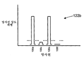
도 2a 및 도 2b를 참조한다. 도 2a는 방사선 센서(102a)로부터 제어기(104)에 의해 얻어지는 방사선 강도 레벨들에 대응하는 방사선 강도 신호(122a)를 도시하고 있다. 도 2b는 방사선 센서(102b)로부터 제어기(104)에 의해 얻어지는 방사선 강도 레벨들에 대응하는 방사선 강도 신호(122b)를 도시하고 있다. 각각의 방사선 강도 신호는 방사원들(106a, 106b, 106c 및 106d)을 포함하는 방사원들이 순차적으로 활성화된 후 비활성화됨에 따른 방사선 센서(102b)의 출력을 포함한다. 임의의 하나의 방사원이 온(on)인 동안에, 나머지 방사원들은 오프이다.Please refer to Figs. 2A and 2B. 2A shows a
제어기(104)는, 방사선 강도 신호들(122a 및 122b)을 이용하여, 방사선 차단 물체(124)의 물리적 위치를 추정할 수 있다. 제어기(104)는, 방사선 차단 물체(124)가 각각의 방사선 센서에 대해 차단된 경로에 로케이팅되는 것으로 상정한다. 이 예에서, 방사선 차단 물체(124)에 대한 위치 P124a(x124a, y124a)는 다음과 같이 추정될 수 있다.The

![]()
![]()
도 1의 실시예에서, 방사선 차단 물체(124)의 위치가 추정될 수 있는 해상도(resolution)는 방사원들(106) 간의 간격을 비롯하여 다수의 인자들에 좌우된다. 방사원들을 서로 가깝게 배치함으로써, 더 높은 해상도가 달성될 수 있다.In the embodiment of FIG. 1, the resolution at which the position of the
위의 수학식 1 및 2에서, 각도들 ![]()
![]()
![]()
![]()
![]()
![]()
![]()
![]()
![]()
![]()
시스템(100)은 제어기(104)의 프로그래밍에 따라 상이한 방식들로 동작될 수 있다.The
다른 실시예에서, 시스템(100)은 표면(128) 상의 방사선 차단 물체의 추정된 위치 P124a를 리파인(refine)하도록 동작될 수 있다. 도 1 및 도 3을 참조한다. 방사원들 간의 거리, 방사선 차단 물체의 치수들, 및 방사선 차단 물체와 방사선 센서 간의 거리에 따라, 몇몇 방사원들과 방사선 센서 간의 경로는 방사선 차단 물체에 의해 차단될 수 있다. 예컨대, 방사원들(106b, 106c 및 106d)이 서로 충분히 가깝다면, 방사선 차단 물체(124)는, 방사원들과 방사선 센서(102b) 중 둘 또는 셋 전부 간의 경로를 적어도 부분적으로 차단함으로써, 특히 방사선 차단 물체가 방사선 센서(102b)에 가깝다면 셋 전부의 방사원들에 대한 방사선 강도 레벨을 감쇄시킬 수 있다. 몇몇 실시예들에서, 제어기(104)는 특정한 방사선 센서에 대한 경로가 차단되는 방사원들의 범위 내에서 중심 방사원을 결정한다. 대안으로, 제어기(104)는, 그 방사선 강도 레벨이 일정한 임계값 레벨 이하인 경우에만 차단되는 것으로 방사원을 처리함으로써, 감쇄된 방사원들 범위의 에지들에서 약간 감쇄된 방사원들을 포함하거나 또는 배제하기 위한 메커니즘을 제공할 수 있다. 이 예에서, 중심 방사원은 방사원(106c)일 것이다. 그 후, 제어기는 중심 방사원과, 프레임(108)의 관련측 간의 각도 θ 또는 ![]()
![]()
![]()
![]()
![]()
![]()
추정된 위치 P124a(x124a, y124a)는, 방사선 센서들(102a 및 102b)을 분리하는 치수 d와 동일한 유닛들로 측정되는 물리적 위치이다.The estimated position P 124a (x 124a , y 124a ) is a physical location measured with units equal to dimension d separating the
몇몇 실시예들에서, 제어기는 전술한 바와 같이 동시적이라기 보다는 순차적으로 방사선 센서들(102) 각각에 대한 방사선 강도 신호(122)를 어셈블할 수 있다. 예컨대, 방사선 센서(102a)에 보여질 수 있는 방사원들이 순차적으로 활성화될 수 있으며, 방사선 강도 신호(122a)가 어셈블될 수 있다. 이어서, 센서(102b)에 보여질 수 있는 방사원들이 순차적으로 활성화될 수 있으며, 방사선 강도 신호(122a)가 어셈블될 수 있다. 동시적이라기보다는 순차적으로, 방사선 강도 신호들(122)을 어셈블하는 이런 프로세스는, 방사원들(106) 중 일부 또는 전부의 강도가 상이한 방사선 센서(102)의 경우 변하도록 허용한다. 도 1을 참조하면, 방사선 센서(106e)는 방사선 센서(102a)보다는 방사선 센서(102b)에 더 가깝다. 방사선 센서(102b)에 대한 방사선 강도 신호를 어셈블할 때보다는 방사선 센서(102a)에 대한 방사선 강도 신호를 어셈블할 때에 더 높은 강도를 갖는 방사원(106e)을 활성화시키는 것이 바람직할 수 있다.In some embodiments, the controller can assemble the radiation intensity signal 122 for each of the radiation sensors 102 sequentially, rather than simultaneously, as described above. For example, the radiation sources visible to the
다른 실시예들에서, 방사선 강도 신호는 동시적으로 어셈블될 수 있지만, 방사원들 중 적어도 일부는 상이한 방사선 센서들에서의 샘플링을 위해 상이한 강도들로 활성화될 수 있다. 예컨대, 몇몇 방사원들은 두 번 이상 활성화될 수 있으며, 상이한 방사선 센서들이 각각의 활성화 동안에 샘플링될 수 있다. 다양한 다른 조합들이 가능하다. 예컨대, 좌측(108) 상의 방사원들은 순차적으로 활성화될 수 있으며, 각각의 방사원이 활성화인 동안에 방사선 센서(102b)가 샘플링될 수 있다. 이어서, 하측(112) 상의 방사원들은 각각 두 번 활성화될 수 있으며, 방사선 센서들(102a, 102b) 각각은 활성화들 중 하나의 활성화 동안에 샘플링될 수 있다. 이어서, 우측(116) 상의 방사원들이 활성화될 수 있으며, 방사선 센서(102a)가 샘플링될 수 있다. 각각의 방사원으로부터 샘플링되는 방사선 강도 레벨들은 그 방사선 센서에 대한 방사선 강도 신호로 어셈블될 수 있다. 다른 실시예에서, 방사선 센서들 양쪽 모두에 가시적인 몇몇 방사선 센서들은 방사선 센서들 각각으로부터 거의 동등하게 이격될 수 있으며, 방사선 센서들은 그 방사원들의 동일한 활성화 동안에 샘플링될 수 있다. 예컨대, 방사원(106b) 및 일부 근접한 방사원들은 방사선 센서들(102a, 102b)로부터 충분히 동등하게 이격되어 방사선 센서들 양쪽 모두가 방사원들 각각의 단일 활성화 동안에 샘플링될 수 있다.In other embodiments, the radiation intensity signal can be assembled simultaneously, but at least some of the radiation sources can be activated with different intensities for sampling at different radiation sensors. For example, some radiation sources may be activated more than once and different radiation sensors may be sampled during each activation. Various other combinations are possible. For example, the radiation sources on the
본 실시예로 돌아가면, 제어기(104)는 인터페이스(148)에 결합되는데, 이 실시예에서 인터페이스는 USB 포트이다.Returning to the present embodiment, the
다른 실시예들에서, 인터페이스는 임의 타입의 통신 인터페이스일 수 있다. 예컨대, 인터페이스(148)는 직렬 데이터 포트 또는 병렬 데이터 포트와 같은 디지털 데이터 인터페이스 또는 아날로그 인터페이스일 수 있다. 인터페이스가 아날로그 인터페이스인 실시예들에서, 제어기는 x124a 및 y124a의 값에 대응하는 (전류 신호 또는 전압 신호와 같은) 아날로그 신호들을 제공할 수 있다. 인터페이스가 디지털 인터페이스인 실시예에서, 제어기는 물리적 위치들 x124a 및 y124a를, 센서들(102a 및 102b)에 대한 대응하는 디지털 위치들 x124d 및 y124d로 변환하도록 구성될 수 있다. 제어기는 인터페이스에서 디지털 위치들 x124d 및 y124d를 제공하도록 구성될 수 있다.In other embodiments, the interface may be any type of communication interface. For example, the
본 실시예에서, 표면(128)은 LCD 디스플레이 스크린의 표면이다. LCD 디스플레이 스크린은 X 수평 픽셀들 × Y 수직 픽셀들의 해상도를 갖는다. 예컨대, 몇몇 실시예들에서, 스크린은 1280 × 1024 픽셀들 또는 1920 × 1080 픽셀들의 해상도를 가질 수 있다. 다른 실시예들에서, 디스플레이 스크린은 임의의 다른 표준 또는 비-표준 픽셀 해상도를 가질 수 있다. 제어기(104)는 물리적 위치를 대응하는 픽셀 위치들 P124d(x124d, y124d)로 변환한다. 제어기(104)는 물리적 위치들 및 픽셀 위치들 간을 변환하는 식을 이용하거나 또는 임의의 다른 방법을 이용하여, 수평 및 수직 물리적 위치들에 대응하는 수평 및 수직 픽셀 위치들을 제공하는 룩업 테이블들의 이용을 비롯하여 다양한 기법들을 이용함으로써 이를 수행하도록 구성될 수 있다. 제어기(104)는 인터페이스(148)에서 디지털 위치 P124d를 제공한다.In this embodiment,
도 1 및 도 4를 참조한다. 다른 실시예에서, 제어기(104)는 상이한 방식으로 방사선 차단 물체(124)의 위치 P124a를 상이하게 추정하도록 구성되거나 또는 프로그래밍된다. 이 실시예에서, 강도 신호들(122)은 각각의 방사선 센서(102)에 대한 방사선 차단 물체(124)의 각도 위치 및 프레임(108)의 측면을 보다 정확히 추정하는데 이용된다.Please refer to Fig. 1 and Fig. In another embodiment, the
도 4는 제어기(104)가 이 실시예에 따라 구성될 때의 방사선 강도 신호(122b)의 일부를 도시하고 있다. 이 실시예에서, 제어기(104)는 각각의 방사선 센서와 결합하여 각각의 방사원에 대한 베이스라인 강도 레벨을 설정한다. 각각의 방사원에 대해, 제어기(104)는, 방사원이 온이고 또한 방사선 차단 물체가 없는 동안에 방사선 센서(102b)로부터 방사선 강도 레벨을 샘플링하여 베이스라인 강도 레벨(126)을 생성한다. 방사원(106a 및 106b-106d)에 대한 베이스라인 강도 레벨들이 도시되어 있다.4 shows a portion of the
이 실시예에서, 시스템의 기동 동안에, 방사원이 가시적인(즉, 방사원과 방사선 센서 간에 직접 경로가 있는 경우) 각각의 방사선 센서에 대한 베이스라인 강도 레벨이 각각의 방사원에 대해 초기에 결정된다. 강도 신호의 샘플들의 초기 세트는 시스템이 기동중인 동안에 폐기된다. 이런 초기 기동 기간에 이어지는 선택된 기간에 대해, 방사원이 온인 동안에 방사선 강도 레벨이 샘플링된다. 방사선 강도 레벨이 기록되고 또한 평균 강도 레벨이 각각의 방사선 센서에서 방사원에 대해 결정된다. 예컨대, 각각의 방사원이 초당 50번 활성화되면, 베이스라인 강도 레벨은, 각각의 방사선 센서에서, 1/2초를 나타내는 각각의 방사원에 대해 첫 번째의 25 샘플들을 이용하여 산출될 수 있다. 다른 실시예들에서, 베이스라인 강도 레벨은 더 많거나 또는 더 적은 샘플들에 대해, 또는 더 긴 기간 또는 더 짧은 기간에 대해 계산될 수 있다. 각각의 방사선 센서에 대한 베이스라인 강도 레벨은, 특정한 방사원이 스위치 온인 때에 방사선 센서에 도달하는 방사량에 영향을 주는 주변 및 다른 조건들을 고유하게 고려한다. 이러한 다른 조건들은 각각의 방사원에 의해 방출되는 방사량, 방사원과 방사선 센서 간의 물리적 거리를 포함하며, 시스템(100)이 이용되는 방식도 포함할 수 있다.In this embodiment, during start-up of the system, the baseline intensity level for each radiation sensor is initially determined for each radiation source when the radiation source is visible (i.e., there is a direct path between the radiation source and the radiation sensor). The initial set of samples of the intensity signal is discarded while the system is running. For the selected period following this initial firing period, the radiation intensity level is sampled while the radiation source is on. The radiation intensity level is recorded and the average intensity level is determined for the radiation source in each radiation sensor. For example, if each radiation source is activated 50 times per second, then the baseline intensity level may be calculated using the first 25 samples for each radiation source representing 1/2 second, in each radiation sensor. In other embodiments, the baseline intensity level may be calculated for more or fewer samples, or for longer periods or shorter periods. The baseline intensity level for each radiation sensor uniquely considers surrounding and other conditions that affect the amount of radiation reaching the radiation sensor when a particular radiation source is switched on. These other conditions include the amount of radiation emitted by each radiation source, the physical distance between the radiation source and the radiation sensor, and may also include the manner in which the
각각의 방사선 센서(102)에 대하여, 각각의 방사원(106)에 대해 계산된 베이스라인 강도 레벨은 시간의 경과에 따라 업데이트될 수 있다. 예컨대, 최근 기간에 대한 방사선 강도 판독들의 일부의 이동 평균은 주변 및 다른 조건들이 변화할 때 베이스라인 레벨을 리파인하도록 계산될 수 있다. 몇몇 방사선 강도 판독들은 업데이트된 베이스라인 강도 레벨을 계산하는데 이용되지 않을 수 있다. 예컨대, 매 10번째 또는 20번째 방사선 강도 판독이 각각의 베이스라인 강도 레벨에 대한 이동 평균을 계산하는데 이용될 수 있다. 이것은, 더 긴 기간에 대응하는 베이스라인 강도 레벨을 계산하기 위해 저장되어야 하는 데이터량을 줄이고 또한 이 임무를 해결하기 위해 제어기에 요구되는 계산 시간을 줄인다. 전형적으로, 베이스라인 강도 레벨은 1초 미만(a part of a second)으로부터 수 초 또는 수십 초까지의 최근 기간에 대해 계산될 것이다. 방사원(106)과 방사선 센서(102) 간의 경로가 차단될 때, 주변 방사선 및 몇몇 방사선이 방사선 차단 물체 주위의 방사선 센서에 여전히 도달할 수 있지만, 방사선 센서에서 방사원에 대한 방사선 강도 레벨은 상당히 줄어들 것이다. 제어기는 추가로 후술하는 바와 같이 베이스라인 강도를 리파인할 때 현재의 베이스라인 강도 레벨에 비해 특정 임계값 미만의 방사선 강도 레벨들을 배제할 수 있다. 각각의 방사선 센서에서 각각의 방사원에 대한 베이스라인 강도 레벨을 계산하기 위한 다양한 다른 방법들이 또한 이용될 수 있다. 몇몇 실시예들에서, 하나의 베이스라인 강도 레벨이 방사선 센서들의 하나의 그룹 또는 방사선 센서들 전부에 대해 계산될 수 있다. 다른 실시예들에서는, 미리 정해진 강도 레벨이 방사원들의 일부 또는 방사원들 전부에 대한 베이스라인 강도 레벨로서 이용될 수 있다.For each radiation sensor 102, the baseline intensity level calculated for each
이 실시예에서, 방사원(106)이 활성화될 때마다, 방사원이 가시적인 각각의 방사선 센서(102)로부터의 방사선 강도 레벨이 샘플링되고 또한 그 방사선 센서에서 그 방사원에 대한 기존의 베이스라인 강도 레벨에 비교된다. 현재의 강도 레벨이 베이스라인 강도 레벨 미만의 일정한 임계값보다 높으면, 베이스라인 레벨로부터의 백분율 차이가 계산된다. 예컨대, 임계값은 베이스라인 강도 레벨의 90%일 수 있다. 현재의 강도 레벨이 베이스라인 레벨의 90%보다 크면, 현재의 강도 레벨은 베이스라인 레벨을 더 리파인하는데 이용될 수 있거나 또는 현재의 강도 레벨은 폐기될 수 있다. 현재의 강도 레벨이 베이스라인 레벨의 90%보다 작으면, 프로세서는 방사원(106)과 방사선 센서(102) 간의 경로가 적어도 부분적으로 차단된 것으로 상정한다. 다른 실시예들에서는, 다른 임계값 레벨들이 이용될 수 있다.In this embodiment, each time the
제어기는 주기적인 프로세스로 방사원들을 연속적으로 활성화시킨다. 방사원들(106)을 스위치 온하고 또한 방사원들에 대해 각각의 방사선 센서로부터 방사선 강도 레벨을 측정하는 각각의 주기 후에, 제어기는 방사선 차단 물체의 위치를 추정한다.The controller continuously activates the radiation sources in a periodic process. After each cycle of switching on the
도 4는 자신의 베이스라인 레벨(126)에 대한 몇 개의 방사원(106)의 감쇄를 도시한다. 방사선 센서(102)에서 측정된, 방사원(106a)에 대한 현재 강도 레벨은 베이스라인 강도 레벨(126a)의 90%보다 커서, 이것은 방사선 차단 물체(124)의 위치 추정의 목적을 위해서는 무시되는데, 그러나 현재 강도 레벨은 방사선 센서(102b)에서 측정된, 방사원(106a)에 대한 베이스라인 레벨을 리파인(refine)하기 위해 이용될 수 있다. 유사하게, 방사원(106b)에 대한 현재 강도 레벨은 베이스라인 강도 레벨(126b)의 90%보다 커서, 방사선 차단 요소의 위치 추정의 목적을 위해서는 무시되지만, 이는 베이스라인 레벨을 리파인하기 위해 이용될 수 있는데, 이 베이스라인 레벨은 그러면 약간 더 높을 것이다.FIG. 4 shows the attenuation of
방사원들(106c 및 106d)에 대한 현재 강도 레벨들은 자신들의 제각기의 베이스라인 레벨들(126c 및 126d)의 90% 아래이다. 방사원(106c)에 대한 현재 강도 레벨은 베이스라인 강도 레벨(126c)의 53%이다. 방사원(106d)에 대한 현재 강도 레벨은 베이스라인 강도 레벨(126d)의 31%이다. 제어기(104)는 이러한 편차들을 총 100%로 정규화(normalize)한다: 방사원(106c)으로부터의 방사선의 상대적인 감쇄는 총 감쇄의 63%를 나타내고(31% / 84% = 63%); 방사원(106d)으로부터의 방사선의 상대적 감쇄는 총 감쇄의 37%를 나타낸다.The current intensity levels for the
그 후, 우측(116)과, 방사원(102b)과 방사선 차단 물체(124) 사이의 라인(132) 사이의 각도 ![]()
![]()
![]()
![]()
![]()
![]()
![]()
![]()

각도 ![]()
![]()
각도들 자체가 기록되는 실시예에서, 각도 ![]()
![]()

각도 ![]()
![]()
각도 θ124가 좌측(114)과, 방사선 센서(102a)와 방사선 차단 물체(124) 사이의 라인 사이의 각도에 대해 계산된다. 두 개의 계산된 각도들 ![]()
![]()
이러한 방식으로, 서로 다른 방사원들의 상대적인 감쇄들을 정규화하고 그 후 방사선 센서 및 프레임의 관련 있는(relevant) 측면으로부터의 이들 방사원들의 각도의 가중화 평균을 계산함으로써, 제어기(104)가 방사선 센서들 중 하나에서 측정된 두 개 이상의 방사원의 감쇄를 이용하여, 방사선 센서들(102) 중 하나와 프레임(108)의 좌측 또는 우측에 대해 상대적인 방사선 차단 물체의 각도 위치를 추정할 수 있다.In this way, by normalizing the relative attenuations of the different radiation sources and then calculating the weighted average of the angles of these radiation sources from the relevant side of the radiation sensor and frame, the
이런 실시예는, 방사원들(106)이 위치되는 특정 각도들 사이에서 각도들 θ 및 ![]()
![]()
시스템(100)은 방사선 차단 물체들(124)의 여러 유형의 위치를 식별하기 위해 여러 구성에서 이용될 수 있다. 예를 들어, 시스템(100)은 화이트보드 또는 다른 디스플레이 표면에서 이용될 수 있다. 프레임(108)은 화이트보드의 에지 또는 프레임에 장착될 수 있고, 또는 화이트보드의 프레임일 수도 있다. 방사선 차단 물체(124)는 화이트보드 상에 기입하는 데에 이용되는 펜일 수 있고, 또한 펜이 화이트보드의 표면 주위에서 움직여질 때 이것의 위치가 제어기(104)에 의해 추정된다. 제어기(104)는 펜의 위치의 추정치들을 기록하기 위해 화이트보드 시스템에 결합될 수 있다(또는 이것의 부분일 수 있다). 펜의 위치의 연속하는 추정치들을 기록함으로써, 화이트보드 상의 정보가 전자적 형태로 재생성될 수 있고 또한 다음 이용을 위해 기록될 수 있고, 또한 이것은 디스플레이되거나 프린트될 수 있다. 화이트보드 시스템은, 추정된 위치들 사이에서의 펜의 움직임의 경로를 산출하고 산출된 경로를 매끄럽게(smooth) 하기 위한 소프트웨어를 포함할 수 있다.The
펜이 화이트보드 상에 기록하는 데에 이용될 때, 화이트보드 상의 잉크가 방사선 센서(102) 상에 반사되는 주변 광의 양을 변화시킬 수 있고 또한 방사원(106)에서부터 방사선 센서(102)로 전파하는 방사선의 양을 또한 변경시킬 수 있는데, 그에 따라 방사원들(106) 중 일부 또는 전부에 대해 측정된 방사선 강도의 레벨에 영향을 미친다. 그러한 실시예들에서, 방사원들 중 일부 또는 전부에 대한 베이스라인 강도 레벨을 주기적으로 갱신하면, 방사선 차단 물체의 위치의 추정들의 정확성을 개선시킬 수 있다.When the pen is used to record on the whiteboard, the ink on the whiteboard can change the amount of ambient light reflected on the radiation sensor 102 and also propagate from the
다른 실시예들에서, 시스템(100)은 디스플레이 모니터 또는 스크린에서 터치 스크린을 형성하는 데에 이용될 수 있다. 프레임(108)은 디스플레이 모니터에 장착될 수 있고 또는 디스플레이 모니터의 하우징의 부분일 수 있다. 이런 경우에, 방사선 차단 물체(124)는 손가락일 수 있고, 사람이 디스플레이 모니터 상으로 또는 모니터 밖으로 자신의 손가락을 움직임에 따라 손가락의 존재가 검출되고 디스플레이 스크린 상의 손가락의 위치가 제어기(104)에 의해 추정된다. 제어기(104)는 (디스플레이 모니터를 또한 포함할 수 있는) 터치 스크린 시스템에 결합될 수 있고 (또는 이것의 부분일 수 있고), 터치 스크린 시스템에게 손가락의 위치의 추정들을 제공할 수 있다. 손가락이 디스플레이 스크린 상에서 그 근처에서 움직임에 따라, 손가락의 위치의 연속적 추정들이, 손가락의 움직임의 전자적 기록을 제공하기 위해 터치 스크린 시스템에 기록될 수 있고 추정된 위치들은 디스플레이 모니터 상에 디스플레이될 수 있다. 터치 스크린 시스템은, 손가락의 연속적인 추정된 위치들 사이의 손가락의 움직임의 경로를 산출하고 산출된 경로를 매끄럽게 하기 위한 소프트웨어 또는 다른 컴포넌트들을 포함할 수 있다. 시스템(100)과 결합한 그러한 터치 스크린 시스템은 사람의 손가락을 이용하여 사용자가 디스플레이 모니터 상에 쓰거나 그리는 것, 또는 디스플레이 모니터상에 디스플레이된 물체들을 조작하는 것을 효과적으로 가능하게 해줄 것이다.In other embodiments, the
터치 스크린 시스템에서, 방사원들(106) 및 방사선 센서들(102)이 디스플레이 스크린에 상대적으로 가깝게 위치될 수 있고 방사선 센서들 상에 입사되는 방사선의 양은 디스플레이 스크린상에 디스플레이되는 정보가 변경됨에 따라 바뀔 수 있다. 그러한 실시예들에서, 방사원들 중 일부 또는 전부에 대한 베이스라인 강도 레벨을 갱신하는 것이 또한 이로울 수 있다.In a touch screen system, the
다음으로 도 5a 및 5b를 참조한다. 도 5a는 방사선 차단 물체(524)의 위치를 추정하기 위한 또 다른 시스템(500)을 도시한다. 도 5b는 시스템(500)의 하부 우측 코너를 더 상세하게 도시한다. 시스템(500)은 시스템(100)과 상당히 유사하고 또한 대응하는 요소들은 대응하는 참조 번호들로 식별된다. 시스템(500)은 방사원들(506)에 인접하게 장착된 확산기들(diffusers)(530)을 포함한다. 확산기들(530)은 방사원들에 의해 방출된 방사선을 확산시킴으로써, 방사선 센서(502)에서 보았을 때, 방사원들에 의해 프레임(508)의 좌측, 하부 및 우측을 따라 명백하게(apparently) 방출된 방사선의 양을 매끄럽게 한다. 본 실시예에서, 방사선 센서들 및 프레임의 좌측 및 우측에 대해 상대적인 방사선 차단 물체(524)의 각도 위치가 시스템(100)과 관련하여 앞서 기술된 바와 같이 추정된다. 본 발명자들은 방사원들(506)에 의해 방출된 방사선을 확산시키는 것이 방사선 차단 물체의 위치의 더 정확한 추정을 제공한다는 것을 발견하였다.Reference is now made to Figures 5a and 5b. FIG. 5A shows another
방사원들로부터의 방사선을 확산시키면서도 지나치게 스캐터링시키지는 않아서 방사선이 방사선 센서들(102)에 의해 정확하게 측정될 수 없게 하는, 약간 흐릿하거나 반투명한 플라스틱 또는 다른 물질들을 포함하여 다양한 물질이 확산기들(530)로서 이용하는 데에 적합하다. 몇몇의 실시예에서, 확산시키지만 실질적으로는 확산기를 통해 통과하는 방사선을 차단하지는 않는 광학적 그레이드 확산기들(optical grade diffusers)이, 회절 격자들(diffraction gratings)을 포함하여 효율적으로 이용될 수 있는데, 렌티큘러 확산기들(lenticular diffusers) 및 렌티큘러 회절 격자들이 확산기들(530)에 이용될 수 있다. 도 5b는 프레임(508)의 하부(512)에 설치된 연속적인 렌티큘러 확산기(530b) 및 프레임(508)의 우측(516)에 설치된 연속적인 렌티큘러 확산기(530r)를 도시한다.Various materials, including slightly hazy or translucent plastics or other materials, that diffuse radiation from the radiation sources while not excessively scattering, such that the radiation can not be accurately measured by the radiation sensors 102, . ≪ / RTI > In some embodiments, optical grade diffusers that diffuse but substantially do not block radiation passing through the diffuser can be efficiently used including diffraction gratings, Lenticular diffusers and lenticular diffraction gratings may be used in diffusers 530. [ 5B shows a continuous
도 6은 도 5b에서 도시된 시스템(500)의 부분에 대응하는 또 다른 실시예(600)의 부분을 도시한다. 시스템(600)에서, 개별적인 확산기들(630)이 각 방사원(506)에 인접하게 설치된다.FIG. 6 illustrates a portion of yet another
본 발명의 몇몇의 실시예에서, 제어기는 방사원들 중 일부 또는 전부에 의해 방출된 방사선의 강도를 바꿀 수 있다. 이것은 방사선 센서들에서 방사원에 대해 측정된 강도 레벨을 바꾸기 위해, 주변 광의 영향을 극복하기 위해, 시스템에 의한 전력 소비를 줄이기 위해, 또는 다른 이유들을 위해 행해질 수 있다.In some embodiments of the invention, the controller can change the intensity of radiation emitted by some or all of the radiation sources. This can be done for radiation sensors to change the intensity level measured against the radiation source, to overcome the effects of ambient light, to reduce power consumption by the system, or for other reasons.
앞서 기술된 실시예들에서, 프레임은 직사각형이고 방사선 센서들은 프레임의 두 개의 코너에 장착된다. 다른 실시예들에서, 프레임은 여러 형상을 가질 수 있다. 예를 들어, 본 발명은 임의의 통상의 또는 변칙적인 형상을 갖는 게시판 또는 다른 물체에서 이용될 수 있고 프레임은 기초가 되는(underlying) 물체상에 또는 이것에 걸쳐 알맞도록 형상화되고 크기 조절될 수 있다. 센서들은 프레임의 (직선이거나 곡선일 수 있는) 측면들을 따라 위치되는 것을 포함하여, 프레임 상의 여러 위치에 배치될 수 있다. 각 경우에, 각 센서의 위치 또는 센서로부터 보이는 방사원들의 위치는 방사선 차단 물체의 존재 및 위치를 식별하도록 기하학적으로 이용된다.In the embodiments described above, the frame is rectangular and the radiation sensors are mounted at two corners of the frame. In other embodiments, the frame may have various shapes. For example, the present invention can be used in a bulletin board or other object having any conventional or anomalous shape, and the frame can be shaped and sized to fit on or over an underlying object . The sensors may be located at various locations on the frame, including those located along the sides of the frame (which may be straight or curved). In each case, the position of each sensor or the position of the radiation sources seen from the sensor is geometrically used to identify the presence and location of the radiation blocking object.
직사각형 또는 다른 프레임 형상들을 갖는 몇몇의 실시예에서, 추가적인 센서들이 이용될 수 있다. 예를 들어, 추가적인 센서들이 시스템(100)(도 1) 및 시스템(500)(도 5a)의 하부 좌측 및 우측 코너들에 추가될 수 있다. 몇몇의 실시예에서, 추가적인 방사원들이 프레임의 상측(110)을 따라 추가될 수 있다. 몇몇의 실시예에서, 추가적인 센서들로부터의 방사선 차단 물체(124 또는 524)의 위치에 대한 추가적인 정보가, 방사선 차단 물체의 위치의 더 정확한 추정을 제공하도록 결합될 수 있다.In some embodiments having rectangular or other frame shapes, additional sensors may be used. For example, additional sensors may be added to the lower left and right corners of system 100 (FIG. 1) and system 500 (FIG. 5A). In some embodiments, additional radiation sources may be added along the
직사각형 또는 다른 프레임 형상들을 갖는 몇몇의 실시예에서, 센서들이 프레임의 측면들을 따라 놓여질 수 있다. 방사선 센서 및 방사원들의 위치는, 방사선 차단 물체가 검출되는 (화이트보드, 디스플레이 모니터 또는 다른 시스템과 같은) 기초가 되는 시스템의 부분에 의존할 수 있다.In some embodiments having rectangular or other frame shapes, the sensors may be placed along the sides of the frame. The location of the radiation sensors and radiation sources may depend on the portion of the underlying system (such as a whiteboard, display monitor or other system) where the radiation shielding object is detected.
여러 실시예에서, 본 발명에 따른 시스템은, 방사원들, 방사선 센서들 및 확산기들을 포함하는 시스템의 컴포넌트들 중 일부 또는 전부를 은폐하는 (프레임의 부분일 수 있는) 베젤(bezel)을 포함할 수 있다. 몇몇의 실시예에서, 베젤 또는 프레임 또는 양자 모두는, 방사선 흡수 페인트로 채색될 수 있고, 또는 이와 달리, 베젤 또는 프레임 또는 양자 모두로부터 방사선 센서들을 향해 반사되는 방사선의 양을 줄이도록 적응될 수 있다.In various embodiments, a system according to the present invention may include a bezel (which may be part of a frame) that conceals some or all of the components of the system including radiation sources, radiation sensors and diffusers have. In some embodiments, the bezel or frame, or both, can be painted with a radiation absorbing paint or, alternatively, can be adapted to reduce the amount of radiation reflected from the bezel or frame, or both, toward the radiation sensors .
몇몇의 실시예에서, 광 필터가 방사선 센서들 중 일부 또는 전부와 방사원들 중 일부 또는 전부 사이에 놓여질 수 있다. 예를 들어, 광 필터는 방사선 센서들로 입사되는 주변 광 및 다른 원하지 않는 방사선의 양을 줄이도록 방사선 센서들의 주위에 설치될 수 있다.In some embodiments, an optical filter may be placed between some or all of the radiation sensors and some or all of the radiation sources. For example, the optical filter may be installed around the radiation sensors to reduce the amount of ambient light and other unwanted radiation incident on the radiation sensors.
다음으로, 두 개 이상의 방사선 차단 물체의 위치를 동시에 추적하기 위한 시스템(700)을 도시한 도 7을 참조한다. 시스템(700)은 연결된 컴퓨터 또는 다른 외부 시스템에 대한 입력 장치 및 출력 장치 양쪽 모두로서 동작하는 터치 스크린이다.Reference is now made to Fig. 7 which shows a
시스템(700)은 구성에 있어서 시스템들(100 및 500)과 유사하고, 대응하는 컴포넌트들은 유사한 참조 번호들에 의해 식별된다. 시스템(700)은 전자 화이트보드 시스템 또는 LCD 터치 스크린으로서 이용될 수 있다.
시스템(700)은 프레임(708) 및 LCD 디스플레이 스크린에 장착된 한 쌍의 방사선 센서들(702a, 702b), 제어기(704), 복수의 방사원(706)을 포함한다. 방사원들(706)은 프레임(708)의 좌측(714), 하측(712) 및 우측(716)에 장착된다. 프레임(708)은 또한 상측(710)을 갖는다. 방사선 센서(702a)는 프레임(708)의 상부 좌측 코너에 장착되고 방사선 센서(702b)는 프레임(708)의 상부 우측 코너에 장착된다. 방사선 센서들(702a 및 702b)은 거리 d만큼 분리된다. 제어기(704)는 방사선 센서들(702) 및 방사원들(706)에 결합된다. 제어기(704)는 시스템(100)에 관련하여 앞서 기술된 바와 같이 방사선 센서들로부터 방사선 강도 레벨들을 수신하고 또한 방사원들을 제어한다.The
프레임(708)의 측면들은 x-y 평면의 축들에 대해 평행하다. 한 쌍의 방사선 차단 물체들(724a 및 724b)은, 각 방사선 차단 물체들(724)이 방사선 센서들(702)과 방사원들(706) 중 적어도 하나 사이의 직선 경로를 막도록 위치된다.The sides of the
LCD 디스플레이 스크린이 프레임(708) 내에 장착되고 또한 디스플레이 표면(728)을 갖는다. 사이트 경로들(sight paths)의 라인(이 라인을 따라 방사원들(706)로부터 방사선 센서들(702)로의 방사가 이루어짐)이 디스플레이 표면 위를 통과하고, 일반적으로 디스플레이 표면과 평행하다. LCD 디스플레이 스크린은 X 수평 픽셀들 × Y 수직 픽셀들의 해상도를 갖는다. 예를 들어, 몇몇의 실시예에서, LCD 디스플레이 스크린은 1280×1024 픽셀들 또는 1920×1080 픽셀들의 해상도를 가질 수 있다. 많은 다른 픽셀 해상도들이 여러 디스플레이 패널에 대해 가능하다. 여러 실시예에서, 임의의 유형의 디스플레이 패널이 LCD 패널 대신에 이용될 수 있다. 전형적으로, 프레임(708)은 디스플레이 패널에 장착되거나 또는 디스플레이 패널의 하우징의 부분을 또한 구성할 것이다.An LCD display screen is mounted within the
시스템(700)은 도 5 및 6에 도시된 확산기들(530 및 630)과 같은 확산기들을 선택적으로 포함할 수 있다.
시스템(700)은 전형적으로 몇 개의 입력/출력 인터페이스를 포함할 것이다. 본 실시예에서, 제어기(704)는 방사선 차단 물체들의 위치를 계산 장치에게 송신하기 위해 인터페이스(748)를 통해 계산 장치에 결합된다. 예를 들어, 인터페이스(748)는 USB 인터페이스와 같은 직렬 인터페이스이거나 병렬 인터페이스일 수 있다. LCD 디스플레이는 비디오 신호 인터페이스(도시 생략)를 통해 디스플레이(728) 상에 디스플레이되는 비디오 신호들을 수신하기 위해 계산 장치에 결합된다.The
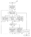
다음으로, 방사선 차단 물체들(724a 및 724b)의 위치들을 식별하거나 추정하기 위한 방법(800)을 도시하는 도 8을 참조한다. 본 실시예에서, 방법(800)은 제어기(704)에 의해 수행된다. 방법(800)을 개시하기 전에, 어떤 방사선 차단 물체도 디스플레이 표면(728) 상에 위치되지 않는다.Reference is now made to Fig. 8, which illustrates a
방법(800)은 방사선 차단 물체(724a)가 디스플레이 표면(728) 상에 최초로 위치되는 단계(802)에서 시작한다. 방법(800)을 수행하기 위한 명령어들이 메모리(721)에 기록된다. 제어기(720)는 저장된 명령어들에 액세스하고 방법을 수행하도록 명령어들을 실행한다.The
방법(800)은 예를 통해, 그리고 예시를 위해 설명될 것인데, 제1 방사선 차단 물체가 도 7에 도시된 위치에서 디스플레이 표면 상에 최초로 놓여진다. 이 단계에서, 방사선 차단 물체(724b)는 디스플레이 표면(728) 상에 놓이지 않는다.
방사선 차단 물체(724a)가 디스플레이 표면(728) 상에 놓여진 후의 방사선 강도 신호들(722a 및 722b)을 도시한 도 9a 및 9b를 참조한다.See FIGS. 9A and 9B showing radiation intensity signals 722a and 722b after the
방사선 강도 신호(722a)는, 방사원들(706i-706k)로부터의 방사선 강도 레벨들이 방사선 센서(702a)에서 감쇄되는 것을 나타낸다. 방사선 강도 신호(722b)는, 방사원(706a-706c)으로부터의 방사선 강도 레벨들이 방사선 센서(702b)에서 감쇄되는 것을 나타낸다.The
제어기(704)가 방사선 차단 물체(724a)의 물리적 위치 P724a(xaa, yaa)를 추정하기 위해, 시스템(100)에 관련하여 앞서 기술된 바와 같이 방사선 강도 신호(722a 및 722b)를 이용한다. 위치 P724a(xaa, yaa)는 센서들(702)의 위치들에 대해 상대적으로 계산된 물리적 (또는 아날로그) 위치이고 또한 각도들(θa, ![]()
![]()
제어기(704)는, 표면(728) 상에서 검출된 각 방사선 차단된 물체의 마지막으로 알려진 위치가 기록된 터치 테이블을 유지한다. 전형적으로, 터치 테이블은 메모리(721)에 저장된 변수들의 세트 또는 데이터베이스의 부분일 수 있다. 본 실시예에서, 터치 테이블은 두 개까지의 방사선 차단 물체의 마지막으로 알려진 위치들을 기록하기 위해 두 개의 슬롯 A 및 B를 포함한다. 다른 실시예들에서, 터치 테이블은 두 개보다 많은 슬롯을 포함할 수 있고 또는 가변 개수의 슬롯을 포함할 수 있다.The
제어기(704)는 터치 테이블에서의 슬롯 A에 제1 방사선 차단 물체(724a)의 물리적 위치 P724a를 기록한다:The

물리적 위치 P724a(xaa, yaa)는 LCD 디스플레이(728) 상에서의 픽셀 (또는 디지털) 위치 P724d(xad, yad)에 대응한다. 제어기(704)는 물리적 위치 P724a를 대응하는 픽셀 위치 P724d로 변환하고 인터페이스(748)에 픽셀 위치 P724d를 제공한다.The physical location P 724a (x aa , y aa ) corresponds to the pixel (or digital) location P 724d (x ad , y ad ) on the
방법(800)은 그러면 단계 804로 진행된다. 단계 804에서, 제어기(704)는 각 방사선 센서(702)로부터 방사원들(706)과 연관된 방사선 강도 레벨들을 순차적으로 얻기 위해 방사원들(706) 및 센서들(702)을 동작시킨다. 각 방사선 센서로부터의 방사선 강도 레벨들이 결합되어 방사선 강도 신호(722)가 생성된다. 제어기(704)는 각 방사선 강도 신호들에서 나타내어지는 방사선 차단 물체들의 수를 판정하기 위해 각 방사선 강도 신호(722)를 분석한다.The
본 실시예에서, 두 개까지의 방사선 차단 물체들이 표면(728) 상에 놓여질 수 있다.In this embodiment, up to two radiation shielding objects may be placed on
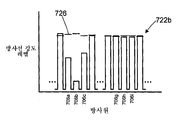
두 개의 방사선 차단 물체(724a 및 724b)가 표면(728) 상에 놓여지는 경우의 예시 방사선 강도 신호들(722a 및 722b)을 도시한 도 10a 및 10b를 참조한다. 각 방사선 강도 신호들(722a 및 722b)은 각 방사원(702)에서 감쇄되는 방사선 강도 레벨들의 두 개의 개별 범위를 갖는다. (방사선 강도 레벨이 감쇄되는 방사원은 감쇄된 방사원으로서 칭해질 수 있다.) 감쇄된 방사선 강도 레벨들의 각 범위는 별개의 방사선 차단 물체(724)에 대응한다. 감쇄된 방사선 강도 레벨들의 범위들은 감쇄되지 않은 적어도 하나의 방사원에 의해 분리된다. 예를 들어, 도 7을 또한 참조하면, 방사선 강도 신호(722a)에서, 방사원들(706i-706k 및 706p-706r)에 대한 방사선 강도 레벨들은 방사선 센서(702a)에서 감쇄된다. 방사원들(706i-706k)의 감쇄는 방사선 차단 물체(724a)에 대응한다. 방사원들(706p-706r)의 감쇄는 방사선 차단 물체(724b)에 대응한다. 제어기(704)는, 감쇄되지 않는 범위들 사이의 적어도 하나의 방사원을 식별함으로써 감쇄되는 방사원들의 2개의 개별 범위들을 식별하도록 구성된다. 어떤 상황에서는, 감쇄되는 방사원들의 범위가 단일 감쇄 방사원으로 이루어질 수 있다.10A and 10B showing exemplary radiation intensity signals 722a and 722b when two radiation blocking objects 724a and 724b are placed on
2개의 방사선 블록들이 표면(728) 위에 배치되는 다른 상황을 도시하고 있는 도 11, 12a 및 12b를 참조한다. 도 11에서, 방사선 차단 물체들(724a 및 724b)은 각도 θa 및 θb가 상대적으로 작은 각도로 분리되도록 배치되어 있다.Reference is made to Figs. 11, 12A and 12B, which show another situation in which two radiation blocks are placed on the
도 12a는 방사선 강도 신호(722a)이며, 이는 방사선 차단 물체들(724a 및 724b)이 하나 이상의 방사원들로부터의 방사선 강도 레벨들의 감쇄에 대한 중복된 효과(overlapping effect)를 갖는다는 것을 나타낸다. 방사선 차단 물체(724a)는 방사원(706i-706l)으로부터의 방사선을 감쇄시키는 것으로 보인다. 방사선 차단 물체(724b)는 방사원(706l-706o)으로부터의 방사선을 감쇄시키는 것으로 보인다. 제어기(704)는, 최소값들 중 어느 하나보다 더 큰 적어도 하나의 방사선 강도 값에 의해 분리되어 있는, 방사선 강도 신호에서의 2개의 개별 최소값들을 식별함으로써 감쇄되는 방사선 신호들의 2개의 범위들을 구분하도록 구성된다. 예를 들어, 도 12a에서, 방사원들(706j 및 706n)에 대한 방사선 강도 레벨들은 국부적인 최소값들이다. 이 국부적인 최소값들은 어느 하나의 최소값들보다 더 큰 몇몇 방사선 강도 레벨들에 의해 분리되어 있다. 여러 실시예에서, 제어기(704)는 2개의 개별적 범위들을 다양한 방법으로 식별하도록 구성될 수 있다. 몇몇 경우에서, 감쇄 방사선 강도 레벨들의 범위는 하나의 감쇄 방사원만을 가질 수 있다. 예를 들어, 몇몇 실시예에서, 제어기(104)는 일정한 사전결정된 양 또는 비율만큼 최소값들을 초과하는 국부적 최소값 방사선 강도 레벨들 사이에서 적어도 하나의 방사선 강도 레벨을 식별하도록 구성될 수 있다. 몇몇 실시예에서, 제어기는 국부적 최소값들 사이에서 방사선 강도 값들 중 적어도 2개(또는 높은 수)를 필요로 하도록 구성된다.12A is a
도 12b는 도 11의 방사선 차단 물체(724a 및 724b)의 위치들에 대응하는 방사선 강도 신호(722b)를 나타낸다. 방사선 강도 신호(722b)는 방사원들(706a-706c 및 706g-706i)에서의 감쇄되는 방사선 강도 레벨들의 2개의 개별 영역을 포함한다. 2개의 범위들은, 감쇄되지 않는 하나 이상의 방사선 강도 레벨들에 의해 분리된다. 제어기(704)는 도 10a 및 10b와 관련하여 전술한 바와 같이 감쇄되는 방사선 강도 레벨들 의 2개의 범위를 구분하도록 구성된다.FIG. 12B shows the
따라서, 제어기(704)는 도 10a, 도 10b, 12a 및 12b에 도시된 방사선 강도 신호들 각각 내의 감쇄되는 방사원들의 범위들을 식별하도록 구성된다.Thus, the
다음으로, 2개의 방사선 차단 물체들(724a 및 724b)가 표면(728) 위에 배치되어 있는 다른 상황을 나타내고 있는 도 13, 14a 및 14b를 참조한다.Next, reference is made to Figures 13, 14a and 14b, which illustrate other situations in which two radiation blocking objects 724a and 724b are disposed on
도 13에서, 2개의 방사선 차단 물체들(724a 및 724b)은 일반적으로 방사선 센서(702a)와 동일선상에 있다. 일반적으로 방사선 차단 물체들과도 동일선상에 있는 방사원(706j)에 의해 방출된 방사선은, 방사선 센서(702a)에 도달하는 것에 대해 방사선 차단 물체(724b)에 의해 적어도 부분적으로 차단된다. 방사선 차단 물체(724a)는 방사원(706j)으로부터의 추가적 방사선이 방사원(702a)에 이르는 것을 차단할 수 있지만, 방사선 차단 물체(724a)는 방사선 차단 물체(724b)의 쉐도우(shadow) 내에 적어도 부분적으로 있다.13, the two radiation blocking objects 724a and 724b are generally collinear with the
도 14a는 도 13의 방사선 차단 물체(724a 및 724b)의 위치들에 대응하는 방사선 강도 신호(722a)를 나타낸다. 방사원들(706i-706k)에 대한 방사선 강도 레벨들은 방사선 차단 물체들(724a 및 724b)에 의해 감쇄된다. 방사선 강도 신호(722a)는 표면(728) 상의 단일 방사선 차단 물체로부터 초래되는 방사선 강도 신호와 유사하다. 제어기(704)는 방사선 강도 신호(722a)를 분석하고, 하나의 분명한 방사선 차단 물체만을 식별할 수 있다.14A shows the
도 14b는 도 13의 방사선 차단 물체(724a 및 724b)의 위치들에 대응하는 방사선 강도 신호(722b)를 나타낸다. 방사선 강도 신호(722b)는 방사원들(706a-706c 및 706d-706f)에서의 감쇄되는 방사선 강도 레벨들의 2개의 개별 영역들을 포함한다. 2개의 영역들은 감쇄되지 않는 하나 이상의 방사선 강도 레벨들에 의해 구분된다. 제어기(704)는, 전술한 바와 같은 감쇄되는 방사선 강도 레벨들의 2개의 영역들을 구분하도록 구성된다.FIG. 14B shows the
따라서, 제어기(704)는 이 단계 804에서 취득되는 방사선 강도 신호들(722a 및 722b) 각각이, 감쇄되는 방사원들의 0개, 1개 또는 2개의 범위들을 포함하는 것으로 보이는지 여부를 판정한다.Thus, the
방법(800)은, 방사선 강도 신호들에서 식별되는 방사선 차단 물체의 수에 따라 단계 804에서부터 다음과 같이 계속된다:The
- 방사선 강도 신호들(722) 각각이 (도 9a 및 9b에 도시된 것과 같이) 감쇄되는 방사원들의 1개의 범위를 포함하는 경우, 방법(800)은 단계 806으로 진행한다: - If each of the radiation intensity signals 722 includes one range of radiation sources attenuated (as shown in FIGS. 9A and 9B), the
- 방사선 강도 신호들(722) 양자 모두가 (도 10a, 10b, 12a 및 12b에 도시된 것과 같이) 감쇄되는 방사원들의 2개의 범위를 포함하는 경우, 방법(800)은 단계 808로 진행한다;If both the radiation intensity signals 722 include two ranges of radiation sources attenuated (as shown in Figures 10a, 10b, 12a and 12b), the
- 방사선 강도 신호들(722) 중 어느 하나가 (도 14a 및 14b에 도시된 바와 같이) 감쇄되는 방사원들의 2개의 범위들을 포함하고, 다른 방사선 강도 신호가 감쇄되는 방사원들의 1개의 범위를 포함하는 경우, 방법(800)은 단계 810으로 진행한다;- when one of the radiation intensity signals 722 comprises two ranges of radiation sources attenuated (as shown in FIGS. 14A and 14B) and the other radiation intensity signal comprises one range of radiation sources to be attenuated , The
- 방사선 강도 신호들(722)의 양자 모두가 감쇄되는 방사원들의 0개의 범위를 포함하는 경우, 방법(800)은 단계 820으로 진행한다;- If both of the radiation intensity signals 722 include zero range of radiation sources to be attenuated, the
- 그렇지 않으면, 방법(800)은 단계 804로 돌아간다;- Otherwise, the
단계 806에서, 제어기(704)는 디스플레이 표면(728) 상의 방사선 차단 물체(724)의 위치를 결정한다. 제어기(704)는, 방사선 강도 신호들(722a 및 722b) 각각 내의 감쇄되는 강도 레벨들의 각 범위들의 가중화 평균 감쇄에 대응하는 각도 θ와 각도 ![]()
![]()
![]()
![]()
만약 하나의 방사선 차단 물체에 대응하는 하나의 위치만이 터치 테이블 내에 기록되는 경우, 교차점은 방사선 차단 물체의 새로운 물리적 위치인 것으로 간주된다. 새로운 위치는 이전에 기록된 위치를 대신하여 터치 테이블 내에 기록된다. 제어기는, 방사선 차단 물체의 물리적 위치를 대응하는 픽셀 위치로 변환하고, 그런 다음 이는 인터페이스(748)에 제공된다.If only one position corresponding to one radiation blocking object is recorded in the touch table, the intersection is considered to be the new physical location of the radiation blocking object. The new location is recorded in the touch table instead of the previously recorded location. The controller translates the physical location of the radiation shielding object to a corresponding pixel location, which is then provided to the
만약 2개의 방사선 차단 물체들에 대응하는 2개의 위치들이 터치 테이블 내에 기록되어 있는 경우, 제어기는 이전에 기록된 위치들 중 어느 것이 교차점에 가장 근접한지를 판정한다. 이 교차점은 가장 근접한 이전에 기록된 위치에 대응하는 방사선 차단 물체의 새로운 위치인 것으로 간주되며, 이는 터치 테이블 내에서 교차점의 위치와 교체된다. 제어기는 방사선 차단 물체의 물리적 위치를 대응하는 픽셀 위치로 변환하고, 그런 다음 이는 인터페이스(748)에서 제공된다.If two positions corresponding to two radiation shielding objects are recorded in the touch table, the controller determines which of the previously recorded positions is closest to the intersection point. This intersection point is considered to be the new position of the radiation blocking object corresponding to the closest previously recorded position, which is replaced with the position of the intersection point within the touch table. The controller converts the physical location of the radiation shielding object to a corresponding pixel location, which is then provided at
더 이전에 기록된 위치는 터치 테이블에서 삭제된다.The previously recorded position is deleted from the touch table.
그 후, 방법(800)은 단계 804로 복귀한다.The
도 7, 10a 및 10b를 추가로 참조한다.7, 10a and 10b.
단계 808에서, 제어기(704)는, 단계 804의 방사선 강도 신호들(722a 및 722b) 각각에서 식별되는 감쇄되는 방사원들의 2개의 범위들에 기초하여 방사선 차단 물체들(724)이 배치될수 있는 다양한 점들을 결정한다.In
예를 들어, 방사선 강도 신호(722a)에서, 방사원들(706i-406k 및 706p-406r)은 방사선 센서(702a)에서 감쇄된다. 감쇄되는 방사원들의 2개의 범위들은 감쇄되지 않는 적어도 하나의 방사원에 의해 구분된다.For example, in the
제어기(704)는, 각도 θ124과 관련하여 전술한 바와 같이, 감쇄되는 센서들의 각 그룹을 독립적으로 분석하고, 방사원들(706i-706k)의 감쇄의 가중화 평균에 기초하여 각도 θa를 계산한다. 각도 θa는 방사선 센서(702a)의 위치를 통해 연장하는 라인(746a)을 규정한다.The
제어기(704)는 또한, 방사원들(706p-706r)의 감쇄에 기초하여 각도 θb를 계산한다. 각도 θb는 센서(702a)의 위치를 통해 연장하는 라인(746b)를 규정한다.The
방사선 강도 신호(722b)에서, 방사원들(706a-706c 및 706g-706i)은 방사선 센서(702b)에서 감쇄된다. 제어기(704)는 방사원들(706a-706c)의 감쇄에 기초하여 각도 ![]()
![]()
![]()
![]()
![]()
![]()
![]()
![]()
라인(746a)은 점들(734 및 736)에서 라인들(732a 및 732b)과 교차한다. 라인(746b)은 라인(732a 및 732b)과 점들(738 및 740)과 교차한다. 4개의 교차점들이 아래 테이블에 도시된다:

4개의 점들(734-740)은 2개의 쌍으로 간주될 수 있다. 방사선 차단 물체들(724a 및 724b)은 점들(734, 740) 또는 점들(736, 738)에 위치할 수 있다. The four points 734-740 may be considered as two pairs. Radiation blocking objects 724a and 724b may be located at
다음으로, 방법(800)은 결정 단계 812로 진행한다.Next, the
단계 810에서, 제어기(704)는, 방사선 강도 신호들(722) 중 하나에서의 감쇄되는 방사원들의 2개의 범위들, 및 다른 방사선 강도 신호에서의 감쇄되는 방사원들의 1개의 범위에 기초하여 방사선 차단 물체들(724a, 724b)이 배치될 수 있는, 다양한 점들을 식별한다.In
도 13, 14a 및 14b를 추가적으로 참조한다.13, 14a and 14b.
방사원들의 2개의 감쇄된 범위들을 갖는 방사선 강도 신호(722)에 대해, 단계 808과 관련하여 기술한 바와 같이, 2개의 각도들 θa 및 θb 또는 ![]()
![]()
![]()
![]()
![]()
![]()
![]()
![]()
감쇄되는 방사원들(706)의 1개의 범위만을 갖는 방사선 강도 신호에 대해, 하나의 대응하는 각도 θ 또는 ![]()
![]()
각도 θa는 각도 θb로서 복제되고, 라인(746a)은 라인(746b)으로서 복제된다.The angle [theta] a is copied as angle [theta] b , and
다음으로, 제어기(704)는, 단계 808에서 기술된 바와 같이, 라인들(746a 및 746b)과 라인들(732a 및 732b)의 교차점들에 기초하여 점들(734-740)을 계산한다.Next, the
다음으로, 방법(800)은 단계 812로 진행한다.Next, the
단계 812에서, 제어기(704)는 터치 테이블에 기록된 위치들의 수를 결정한다. 만약 터치 테이블 내에 하나의 위치만이 기록되어 있는 경우, 방법(800)은 단계 812로 진행한다. 만약 터치 테이블 내에 2개의 위치들이 기록되어 있는 경우, 방법(800)은 단계 814로 진행한다. In
단계 814는 하나의 방사선 차단의 위치가 터치 테이블 내에 기록되어 있는 경우에 수행되며, 하나의 추가적인 방사선 차단 물체가, 감쇄되는 방사원들의 2개의 범위들을 갖는 방사선 강도 신호들(722a 또는 722b) 중 적어도 하나 양자 모두에 기초하여, 새롭게 식별된다.Step 814 is performed when the position of one radiation shield is recorded in the touch table, and one additional radiation shielding object is positioned on at least one of the radiation intensity signals 722a or 722b having two ranges of radiation sources to be attenuated Are newly identified based on both.
제어기(704)는 어느 점들(734 및 740, 또는 736 및 738)이 2개의 방사선 차단 물체들(724a 및 724b)에 대응하는지 판정한다.The
제어기(704)는 어느 점(734-440)이 터치 테이블 내에 기록되어 있는 위치와 가장 근접한지를 판정한다. 이 예에서, 방사선 차단 물체(724a)의 물리적 위치 P1a는 단계 806에서 터치 테이블의 슬롯 A 내에 기록되었다. (점들(734-740) 중에서) 미리 알려진 위치 P1a에 가장 근접한 점이 제1 방사선 차단 물체(724a)의 현재 위치 P1a인 것으로 간주된다. 위치 P1a는 점들의 쌍들(734 및 740, 또는 736 및 738) 중 한 쌍 내의 한 점에 대응할 것이다. 동일 쌍 내의 다른 점은 제2 방사선 차단 물체(724b)의 위치 P2a(xba, yba)인 것으로 간주된다. 예를 들어, 도 7에 도시된 예에서, 방사선 차단 물체(724a)에 대해 가장 마지막으로 공지된 위치 P1a는 위치(734)에 가장 근접한다. 방사선 차단 물체(724a)는 점(734)에 위치하는 것으로 간주되며, 제2 방사선 차단 물체(724b)의 위치 P2a는 점(740)인 것으로 간주된다.The
제어기(704)는 터치 테이블의 슬롯 A 내의 제1 방사선 차단 물체(724a)의 위치 P1a로 터치 테이블을 업데이트하고, 터치 테이블의 슬롯 B 내에 제2 방사선 차단 물체(724b)의 위치 P2a를 기록한다: The

제어기(704)는, 방사선 차단 물체들(724a, 724b)의 물리적인 위치들(P1a, P2a)을 대응하는 픽셀 위치들(P1d, P2d)로 변환하고, 인터페이스(748)에서 그것들을 결합된 컴퓨팅 장치에 제공한다.The
그 후에, 방법(800)은 단계 804로 복귀한다.Thereafter, the
단계 816에서, 제1 및 제2 방사선 차단 물체(724)의 위치들은, 그것들이 디스플레이 표면(728) 상에서 이동할 때 추적된다.In
방법(800)은, (단계 814 또는 816에서) 터치 테이블이 사전에 2개의 방사선 차단 물체(724)의 위치들로 갱신된 경우라면 단계 816에 도달한다. 2개의 방사선 차단 물체들의 위치들이 터치 테이블에서 갱신되고, 그것들의 각 위치들은 인터페이스(748)에 보고된다.The
제어기(704)는, 터치 테이블에 마지막으로 기록된 위치들(P1a, P2a)로부터 각각의 가능한 움직임들의 조합을 분석한다. 이 실시예에서, 4개의 가능한 조합들은 아래와 같다:The
조합 1: 방사선 차단 물체(724a)는 위치 734로 이동됨; 및Combination 1: the
방사선 차단 물체(724b)는 위치 740으로 이동됨. The
조합 2: 방사선 차단 물체(724a)는 위치 740으로 이동됨; 및Combination 2:
방사선 차단 물체(724b)는 위치 734로 이동됨. The
조합 3: 방사선 차단 물체(724a)는 위치 736으로 이동됨; 및Combination 3:
방사선 차단 물체(724b)는 위치 738로 이동됨. The
조합 4: 방사선 차단 물체(724a)는 위치 738로 이동됨; 및Combination 4: the
방사선 차단 물체(724b)는 위치 736으로 이동됨. The
각각의 조합에 대해, 제어기(704)는, 2개의 방사선 차단 물체들(724)이 움직인 총 거리를 산출하도록 구성된다. 예를 들면, 조합 3의 경우에, 제1 방사선 차단 물체(724a)는 위치 P1a로부터 위치 736까지 움직였을 것이고, 제2 방사선 차단 물체(724b)는, 위치 P2a로부터 위치 738까지 움직였을 것이다. 각 방사선 차단 물체가 움직인 거리는 표준 기하학적 기법들을 이용하여 산출될 수 있다.For each combination, the
각각의 조합에 대해서, 각 방사선 차단 물체가 움직인 거리들은 서로 합산된다. 이 실시예에서는, 각 조합에서 아래와 같은 총 거리들이 산출된다:For each combination, the distance traveled by each radiation shield is summed together. In this embodiment, the following total distances are calculated in each combination:
조합 1: 0.2mmCombination 1: 0.2 mm
조합 2: 82.4mmCombination 2: 82.4 mm
조합 3: 46.5mmCombination 3: 46.5mm
조합 4: 85.3mmCombination 4: 85.3mm
제어기(704)는, 방사선 차단 물체들이 2개의 방사선 차단 물체들의 총 움직임이 가장 짧은 것을 요구하는 조합에 따라 움직인 것으로 간주되도록 구성된다. 현재 실시예에서, 이것은 조합 1이다. 방사선 차단 물체(724a)는 점(734)로 움직인 것으로 간주된다. 방사선 차단 물체(724b)는 점(740)으로 움직인 것으로 간주된다. 제어기(704)는, 터치 테이블을 각 방사선 차단 물체의 새로운 위치로 갱신한다. 제어기(704)는, 방사선 차단 물체들(724a, 724b)의 새로운 물리적 위치들(P1a, P2a)을 대응하는 픽셀 위치들(P1d, P2d)로 변환하고, 인터페이스(748)에서 그것들을 결합된 컴퓨팅 장치에 제공한다.The
그 후에, 방법(800)은 단계 804로 복귀한다.Thereafter, the
방법(800)은, 방사선 차단 물체들 양자 모두가 디스플레이 표면(728)으로부터 제거된 경우에 단계 820에 도달한다. 제어기는, 터치 테이블에 기록된 모든 위치들을 삭제하고, 방사선 차단 물체들이 디스플레이 표면(728) 상에서 검출되지 않았다는 표시를 인터페이스(748)에 선택적으로 제공할 수 있다.The
방법 800을 이용하면, 제어기(704)는 하나 또는 2개의 방사선 차단 물체들의 연속적인 위치들을, 그것들이 디스플레이 표면(728)에 위치하고 디스플레이 표면(728) 주위로 이동할 때 제공한다. 본 방법은, 방사선 차단 물체가 디스플레이 표면 상에서 식별되지 않을 때에 종료된다.Using the
시스템(700) 및 방법(800)에서, 방사선 차단 물체들의 위치들은 물리적 위치들로서 터치 테이블에 기록되고, 다양한 지점들 간의 거리들은 물리적인 치수로 산출된다. 다른 실시예들에서, 위치들이 기록될 수 있으며, 거리들은 픽셀 치수들로 산출될 수 있다.In
본 발명은 여기에 단지 예시의 방식으로써 기술되었다. 본 발명의 사상 및 범위를 벗어나지 않고, 다양한 변경 및 변형들이 본 예시적인 실시예들에 대해 행해질 수 있다.The invention has been described herein by way of example only. Various changes and modifications can be made to the exemplary embodiments without departing from the spirit and scope of the invention.
Claims (1)
Applications Claiming Priority (5)
| Application Number | Priority Date | Filing Date | Title |
|---|---|---|---|
| US21812409P | 2009-06-18 | 2009-06-18 | |
| US61/218,124 | 2009-06-18 | ||
| US32033410P | 2010-04-02 | 2010-04-02 | |
| US61/320,334 | 2010-04-02 | ||
| PCT/CA2010/000961 WO2010145038A1 (en) | 2009-06-18 | 2010-06-18 | Systems and methods for sensing and tracking radiation blocking objects on a surface |
Related Parent Applications (1)
| Application Number | Title | Priority Date | Filing Date |
|---|---|---|---|
| KR1020127001493A Division KR101814515B1 (en) | 2009-06-18 | 2010-06-18 | Systems and methods for sensing and tracking radiation blocking objects on a surface |
Publications (1)
| Publication Number | Publication Date |
|---|---|
| KR20170103987A true KR20170103987A (en) | 2017-09-13 |
Family
ID=43355654
Family Applications (2)
| Application Number | Title | Priority Date | Filing Date |
|---|---|---|---|
| KR1020127001493A KR101814515B1 (en) | 2009-06-18 | 2010-06-18 | Systems and methods for sensing and tracking radiation blocking objects on a surface |
| KR1020177024438A KR20170103987A (en) | 2009-06-18 | 2010-06-18 | Systems and methods for sensing and tracking radiation blocking objects on a surface |
Family Applications Before (1)
| Application Number | Title | Priority Date | Filing Date |
|---|---|---|---|
| KR1020127001493A KR101814515B1 (en) | 2009-06-18 | 2010-06-18 | Systems and methods for sensing and tracking radiation blocking objects on a surface |
Country Status (7)
| Country | Link |
|---|---|
| US (2) | US20130120315A1 (en) |
| EP (1) | EP2443481B1 (en) |
| JP (2) | JP2012530303A (en) |
| KR (2) | KR101814515B1 (en) |
| CN (1) | CN102597813B (en) |
| CA (1) | CA2763173A1 (en) |
| WO (1) | WO2010145038A1 (en) |
Families Citing this family (15)
| Publication number | Priority date | Publication date | Assignee | Title |
|---|---|---|---|---|
| US8061562B2 (en) | 2004-10-12 | 2011-11-22 | S.C. Johnson & Son, Inc. | Compact spray device |
| BR112012031234A2 (en) | 2010-06-09 | 2016-10-25 | Baanto Internat Ltd | "modular position sensor system and methods" |
| WO2012027829A1 (en) * | 2010-09-02 | 2012-03-08 | Baanto International Ltd. | Systems and methods for sensing and tracking radiation blocking objects on a surface |
| TWI456461B (en) * | 2011-06-07 | 2014-10-11 | Wintek Corp | Touch-sensitive device |
| CN102830852A (en) * | 2011-06-13 | 2012-12-19 | 联胜(中国)科技有限公司 | Touch device |
| US20140226084A1 (en) * | 2011-06-15 | 2014-08-14 | Baanto International Ltd. | Mounting Systems for Modular Position Sensing Systems |
| WO2013043684A2 (en) | 2011-09-19 | 2013-03-28 | S. C. Johnson & Son, Inc. | Spray dispenser |
| US9108782B2 (en) | 2012-10-15 | 2015-08-18 | S.C. Johnson & Son, Inc. | Dispensing systems with improved sensing capabilities |
| US9310512B1 (en) * | 2014-08-07 | 2016-04-12 | Polestar Technologies, Inc. | Methods and systems for detection and identification of concealed materials |
| KR102355516B1 (en) * | 2015-04-30 | 2022-01-26 | 삼성디스플레이 주식회사 | Touch screen display device and driving method thereof |
| CN105281666B (en) * | 2015-10-22 | 2017-07-14 | 河海大学常州校区 | A kind of method for improving solar cell irradiation sensor measuring accuracy |
| JP2019159865A (en) * | 2018-03-14 | 2019-09-19 | 富士通株式会社 | Control program, control method, and information processing apparatus |
| CA3100551A1 (en) | 2018-05-18 | 2019-11-21 | 1004335 Ontario Inc. carrying on business as A D Metro | Optical touch sensor devices and systems |
| IT201900007040A1 (en) | 2019-05-21 | 2020-11-21 | Centro Di Ricerca Sviluppo E Studi Superiori In Sardegna Crs4 Srl Uninominale | System for detecting interactions with a surface |
| CA3113946A1 (en) | 2020-04-03 | 2021-10-03 | 1004335 Ontario Inc. | Optical touch sensor systems and optical detectors with noise mitigation |
Family Cites Families (26)
| Publication number | Priority date | Publication date | Assignee | Title |
|---|---|---|---|---|
| US4507557A (en) * | 1983-04-01 | 1985-03-26 | Siemens Corporate Research & Support, Inc. | Non-contact X,Y digitizer using two dynamic ram imagers |
| JPS61254805A (en) * | 1985-05-07 | 1986-11-12 | Victor Co Of Japan Ltd | Position detector |
| US5107253A (en) * | 1989-11-13 | 1992-04-21 | Tektronix, Inc. | Stylus position detection system for optical touch panel |
| US5317140A (en) * | 1992-11-24 | 1994-05-31 | Dunthorn David I | Diffusion-assisted position location particularly for visual pen detection |
| JPH07261911A (en) * | 1994-03-22 | 1995-10-13 | Dowa Mining Co Ltd | Optical fiber type touch panel |
| JP2000284896A (en) * | 1999-03-31 | 2000-10-13 | Fujitsu General Ltd | Optical scanning touch panel |
| WO2001040922A2 (en) * | 1999-12-02 | 2001-06-07 | Elo Touchsystems, Inc. | Apparatus and method to improve resolution of infrared touch systems |
| EP1128318A3 (en) * | 2000-02-21 | 2002-01-23 | Cyberboard A/S | Position detection device |
| JP2001265515A (en) * | 2000-03-22 | 2001-09-28 | Newcom:Kk | Position indicator with light shielding member and optical system coordinate input device using the same |
| US6690363B2 (en) * | 2000-06-19 | 2004-02-10 | Next Holdings Limited | Touch panel display system |
| JP4335468B2 (en) * | 2001-03-14 | 2009-09-30 | 株式会社リコー | Information input / output system, information control method, program, and recording medium |
| US20020175900A1 (en) * | 2001-04-04 | 2002-11-28 | Armstrong Donald B. | Touch input system |
| JP3952896B2 (en) | 2002-07-30 | 2007-08-01 | キヤノン株式会社 | Coordinate input device, control method therefor, and program |
| KR101035253B1 (en) | 2003-02-14 | 2011-05-19 | 넥스트 홀딩즈 리미티드 | Touch screen signal processing |
| JP4522113B2 (en) * | 2004-03-11 | 2010-08-11 | キヤノン株式会社 | Coordinate input device |
| US7519223B2 (en) * | 2004-06-28 | 2009-04-14 | Microsoft Corporation | Recognizing gestures and using gestures for interacting with software applications |
| EP1859339A2 (en) | 2005-03-10 | 2007-11-28 | Koninklijke Philips Electronics N.V. | System and method for detecting the location, size and shape of multiple objects that interact with a touch screen display |
| JP4590295B2 (en) * | 2005-04-15 | 2010-12-01 | キヤノン株式会社 | Coordinate input device, control method therefor, and program |
| US7439291B2 (en) | 2005-09-14 | 2008-10-21 | General Electric Company | Solvent-resistant membranes from solvent-inert polyimides and polyketones |
| JP4757144B2 (en) * | 2006-08-22 | 2011-08-24 | キヤノン株式会社 | Coordinate input device, control method therefor, and program |
| DE602007010801D1 (en) | 2006-09-13 | 2011-01-05 | Koninkl Philips Electronics Nv | DETERMINING THE ORIENTATION OF AN OBJECT |
| JP2008250897A (en) * | 2007-03-30 | 2008-10-16 | Ricoh Elemex Corp | Coordinate input device |
| KR20100055516A (en) * | 2007-08-30 | 2010-05-26 | 넥스트 홀딩스 인코포레이티드 | Optical touchscreen with improved illumination |
| TWI339808B (en) * | 2007-09-07 | 2011-04-01 | Quanta Comp Inc | Method and system for distinguishing multiple touch points |
| CN100501657C (en) * | 2007-11-05 | 2009-06-17 | 广东威创视讯科技股份有限公司 | Touch panel device and its locating method |
| JP5049747B2 (en) * | 2007-11-09 | 2012-10-17 | キヤノン株式会社 | Coordinate input device, control method therefor, and program |
-
2010
- 2010-06-18 JP JP2012515304A patent/JP2012530303A/en active Pending
- 2010-06-18 US US13/379,476 patent/US20130120315A1/en not_active Abandoned
- 2010-06-18 WO PCT/CA2010/000961 patent/WO2010145038A1/en active Application Filing
- 2010-06-18 EP EP10788579.0A patent/EP2443481B1/en active Active
- 2010-06-18 CA CA2763173A patent/CA2763173A1/en not_active Abandoned
- 2010-06-18 CN CN201080036262.3A patent/CN102597813B/en active Active
- 2010-06-18 KR KR1020127001493A patent/KR101814515B1/en active IP Right Grant
- 2010-06-18 KR KR1020177024438A patent/KR20170103987A/en not_active Application Discontinuation
-
2015
- 2015-08-03 JP JP2015153485A patent/JP6086952B2/en active Active
-
2018
- 2018-02-12 US US15/894,563 patent/US10627973B2/en active Active
Also Published As
| Publication number | Publication date |
|---|---|
| JP2015195058A (en) | 2015-11-05 |
| CA2763173A1 (en) | 2010-12-23 |
| KR101814515B1 (en) | 2018-01-04 |
| EP2443481A1 (en) | 2012-04-25 |
| CN102597813B (en) | 2017-11-14 |
| US20180164926A1 (en) | 2018-06-14 |
| JP2012530303A (en) | 2012-11-29 |
| JP6086952B2 (en) | 2017-03-01 |
| EP2443481A4 (en) | 2017-11-01 |
| KR20120037945A (en) | 2012-04-20 |
| CN102597813A (en) | 2012-07-18 |
| US20130120315A1 (en) | 2013-05-16 |
| US10627973B2 (en) | 2020-04-21 |
| WO2010145038A1 (en) | 2010-12-23 |
| EP2443481B1 (en) | 2021-05-19 |
Similar Documents
| Publication | Publication Date | Title |
|---|---|---|
| KR101814515B1 (en) | Systems and methods for sensing and tracking radiation blocking objects on a surface | |
| US9453726B2 (en) | Systems and methods for sensing and tracking radiation blocking objects on a surface | |
| US20100295821A1 (en) | Optical touch panel | |
| US20130135259A1 (en) | Robust Optical Touch - Screen Systems And Methods Using A Planar Transparent Sheet | |
| US20110261016A1 (en) | Optical touch screen system and method for recognizing a relative distance of objects | |
| US9582116B2 (en) | Systems and methods for sensing and tracking radiation blocking objects on a surface | |
| EP2443471A1 (en) | Two-dimensional position sensing systems and sensors therefor | |
| US20170170826A1 (en) | Optical sensor based mechanical keyboard input system and method | |
| JP2007504492A5 (en) | ||
| CN107077257A (en) | Detected using the screen contact of total internal reflection | |
| JP3085482U (en) | Input device |
Legal Events
| Date | Code | Title | Description |
|---|---|---|---|
| A107 | Divisional application of patent | ||
| E902 | Notification of reason for refusal | ||
| E601 | Decision to refuse application |