KR20170097833A - Chemical supplying apparatus and substrate treating apparatus - Google Patents
Chemical supplying apparatus and substrate treating apparatus Download PDFInfo
- Publication number
- KR20170097833A KR20170097833A KR1020160019313A KR20160019313A KR20170097833A KR 20170097833 A KR20170097833 A KR 20170097833A KR 1020160019313 A KR1020160019313 A KR 1020160019313A KR 20160019313 A KR20160019313 A KR 20160019313A KR 20170097833 A KR20170097833 A KR 20170097833A
- Authority
- KR
- South Korea
- Prior art keywords
- chemical liquid
- coupler
- container
- liquid supply
- holder
- Prior art date
Links
Images


Classifications
-
- G—PHYSICS
- G03—PHOTOGRAPHY; CINEMATOGRAPHY; ANALOGOUS TECHNIQUES USING WAVES OTHER THAN OPTICAL WAVES; ELECTROGRAPHY; HOLOGRAPHY
- G03F—PHOTOMECHANICAL PRODUCTION OF TEXTURED OR PATTERNED SURFACES, e.g. FOR PRINTING, FOR PROCESSING OF SEMICONDUCTOR DEVICES; MATERIALS THEREFOR; ORIGINALS THEREFOR; APPARATUS SPECIALLY ADAPTED THEREFOR
- G03F7/00—Photomechanical, e.g. photolithographic, production of textured or patterned surfaces, e.g. printing surfaces; Materials therefor, e.g. comprising photoresists; Apparatus specially adapted therefor
- G03F7/16—Coating processes; Apparatus therefor
-
- H—ELECTRICITY
- H01—ELECTRIC ELEMENTS
- H01L—SEMICONDUCTOR DEVICES NOT COVERED BY CLASS H10
- H01L21/00—Processes or apparatus adapted for the manufacture or treatment of semiconductor or solid state devices or of parts thereof
- H01L21/02—Manufacture or treatment of semiconductor devices or of parts thereof
- H01L21/02104—Forming layers
- H01L21/02107—Forming insulating materials on a substrate
- H01L21/02296—Forming insulating materials on a substrate characterised by the treatment performed before or after the formation of the layer
- H01L21/02299—Forming insulating materials on a substrate characterised by the treatment performed before or after the formation of the layer pre-treatment
- H01L21/02307—Forming insulating materials on a substrate characterised by the treatment performed before or after the formation of the layer pre-treatment treatment by exposure to a liquid
-
- H—ELECTRICITY
- H01—ELECTRIC ELEMENTS
- H01L—SEMICONDUCTOR DEVICES NOT COVERED BY CLASS H10
- H01L21/00—Processes or apparatus adapted for the manufacture or treatment of semiconductor or solid state devices or of parts thereof
- H01L21/02—Manufacture or treatment of semiconductor devices or of parts thereof
- H01L21/02104—Forming layers
- H01L21/02107—Forming insulating materials on a substrate
- H01L21/02296—Forming insulating materials on a substrate characterised by the treatment performed before or after the formation of the layer
- H01L21/02318—Forming insulating materials on a substrate characterised by the treatment performed before or after the formation of the layer post-treatment
- H01L21/02343—Forming insulating materials on a substrate characterised by the treatment performed before or after the formation of the layer post-treatment treatment by exposure to a liquid
-
- H—ELECTRICITY
- H01—ELECTRIC ELEMENTS
- H01L—SEMICONDUCTOR DEVICES NOT COVERED BY CLASS H10
- H01L21/00—Processes or apparatus adapted for the manufacture or treatment of semiconductor or solid state devices or of parts thereof
- H01L21/02—Manufacture or treatment of semiconductor devices or of parts thereof
- H01L21/02104—Forming layers
- H01L21/02365—Forming inorganic semiconducting materials on a substrate
- H01L21/02612—Formation types
- H01L21/02617—Deposition types
- H01L21/02623—Liquid deposition
- H01L21/02628—Liquid deposition using solutions
-
- H—ELECTRICITY
- H01—ELECTRIC ELEMENTS
- H01L—SEMICONDUCTOR DEVICES NOT COVERED BY CLASS H10
- H01L21/00—Processes or apparatus adapted for the manufacture or treatment of semiconductor or solid state devices or of parts thereof
- H01L21/02—Manufacture or treatment of semiconductor devices or of parts thereof
- H01L21/027—Making masks on semiconductor bodies for further photolithographic processing not provided for in group H01L21/18 or H01L21/34
- H01L21/0271—Making masks on semiconductor bodies for further photolithographic processing not provided for in group H01L21/18 or H01L21/34 comprising organic layers
- H01L21/0273—Making masks on semiconductor bodies for further photolithographic processing not provided for in group H01L21/18 or H01L21/34 comprising organic layers characterised by the treatment of photoresist layers
- H01L21/0274—Photolithographic processes
-
- H—ELECTRICITY
- H01—ELECTRIC ELEMENTS
- H01L—SEMICONDUCTOR DEVICES NOT COVERED BY CLASS H10
- H01L21/00—Processes or apparatus adapted for the manufacture or treatment of semiconductor or solid state devices or of parts thereof
- H01L21/67—Apparatus specially adapted for handling semiconductor or electric solid state devices during manufacture or treatment thereof; Apparatus specially adapted for handling wafers during manufacture or treatment of semiconductor or electric solid state devices or components ; Apparatus not specifically provided for elsewhere
- H01L21/67005—Apparatus not specifically provided for elsewhere
- H01L21/67011—Apparatus for manufacture or treatment
- H01L21/67017—Apparatus for fluid treatment
-
- H—ELECTRICITY
- H01—ELECTRIC ELEMENTS
- H01L—SEMICONDUCTOR DEVICES NOT COVERED BY CLASS H10
- H01L21/00—Processes or apparatus adapted for the manufacture or treatment of semiconductor or solid state devices or of parts thereof
- H01L21/67—Apparatus specially adapted for handling semiconductor or electric solid state devices during manufacture or treatment thereof; Apparatus specially adapted for handling wafers during manufacture or treatment of semiconductor or electric solid state devices or components ; Apparatus not specifically provided for elsewhere
- H01L21/67005—Apparatus not specifically provided for elsewhere
- H01L21/67011—Apparatus for manufacture or treatment
- H01L21/67126—Apparatus for sealing, encapsulating, glassing, decapsulating or the like
-
- H—ELECTRICITY
- H01—ELECTRIC ELEMENTS
- H01L—SEMICONDUCTOR DEVICES NOT COVERED BY CLASS H10
- H01L21/00—Processes or apparatus adapted for the manufacture or treatment of semiconductor or solid state devices or of parts thereof
- H01L21/67—Apparatus specially adapted for handling semiconductor or electric solid state devices during manufacture or treatment thereof; Apparatus specially adapted for handling wafers during manufacture or treatment of semiconductor or electric solid state devices or components ; Apparatus not specifically provided for elsewhere
- H01L21/67005—Apparatus not specifically provided for elsewhere
- H01L21/67011—Apparatus for manufacture or treatment
- H01L21/6715—Apparatus for applying a liquid, a resin, an ink or the like
-
- H—ELECTRICITY
- H01—ELECTRIC ELEMENTS
- H01L—SEMICONDUCTOR DEVICES NOT COVERED BY CLASS H10
- H01L21/00—Processes or apparatus adapted for the manufacture or treatment of semiconductor or solid state devices or of parts thereof
- H01L21/67—Apparatus specially adapted for handling semiconductor or electric solid state devices during manufacture or treatment thereof; Apparatus specially adapted for handling wafers during manufacture or treatment of semiconductor or electric solid state devices or components ; Apparatus not specifically provided for elsewhere
- H01L21/67005—Apparatus not specifically provided for elsewhere
- H01L21/67011—Apparatus for manufacture or treatment
- H01L21/67155—Apparatus for manufacturing or treating in a plurality of work-stations
- H01L21/6719—Apparatus for manufacturing or treating in a plurality of work-stations characterized by the construction of the processing chambers, e.g. modular processing chambers
-
- H—ELECTRICITY
- H01—ELECTRIC ELEMENTS
- H01L—SEMICONDUCTOR DEVICES NOT COVERED BY CLASS H10
- H01L21/00—Processes or apparatus adapted for the manufacture or treatment of semiconductor or solid state devices or of parts thereof
- H01L21/67—Apparatus specially adapted for handling semiconductor or electric solid state devices during manufacture or treatment thereof; Apparatus specially adapted for handling wafers during manufacture or treatment of semiconductor or electric solid state devices or components ; Apparatus not specifically provided for elsewhere
- H01L21/683—Apparatus specially adapted for handling semiconductor or electric solid state devices during manufacture or treatment thereof; Apparatus specially adapted for handling wafers during manufacture or treatment of semiconductor or electric solid state devices or components ; Apparatus not specifically provided for elsewhere for supporting or gripping
- H01L21/687—Apparatus specially adapted for handling semiconductor or electric solid state devices during manufacture or treatment thereof; Apparatus specially adapted for handling wafers during manufacture or treatment of semiconductor or electric solid state devices or components ; Apparatus not specifically provided for elsewhere for supporting or gripping using mechanical means, e.g. chucks, clamps or pinches
-
- B—PERFORMING OPERATIONS; TRANSPORTING
- B65—CONVEYING; PACKING; STORING; HANDLING THIN OR FILAMENTARY MATERIAL
- B65D—CONTAINERS FOR STORAGE OR TRANSPORT OF ARTICLES OR MATERIALS, e.g. BAGS, BARRELS, BOTTLES, BOXES, CANS, CARTONS, CRATES, DRUMS, JARS, TANKS, HOPPERS, FORWARDING CONTAINERS; ACCESSORIES, CLOSURES, OR FITTINGS THEREFOR; PACKAGING ELEMENTS; PACKAGES
- B65D47/00—Closures with filling and discharging, or with discharging, devices
- B65D47/04—Closures with discharging devices other than pumps
-
- B—PERFORMING OPERATIONS; TRANSPORTING
- B67—OPENING, CLOSING OR CLEANING BOTTLES, JARS OR SIMILAR CONTAINERS; LIQUID HANDLING
- B67D—DISPENSING, DELIVERING OR TRANSFERRING LIQUIDS, NOT OTHERWISE PROVIDED FOR
- B67D1/00—Apparatus or devices for dispensing beverages on draught
- B67D1/08—Details
- B67D1/0829—Keg connection means
-
- B—PERFORMING OPERATIONS; TRANSPORTING
- B67—OPENING, CLOSING OR CLEANING BOTTLES, JARS OR SIMILAR CONTAINERS; LIQUID HANDLING
- B67D—DISPENSING, DELIVERING OR TRANSFERRING LIQUIDS, NOT OTHERWISE PROVIDED FOR
- B67D7/00—Apparatus or devices for transferring liquids from bulk storage containers or reservoirs into vehicles or into portable containers, e.g. for retail sale purposes
- B67D7/02—Apparatus or devices for transferring liquids from bulk storage containers or reservoirs into vehicles or into portable containers, e.g. for retail sale purposes for transferring liquids other than fuel or lubricants
- B67D7/0238—Apparatus or devices for transferring liquids from bulk storage containers or reservoirs into vehicles or into portable containers, e.g. for retail sale purposes for transferring liquids other than fuel or lubricants utilising compressed air or other gas acting directly or indirectly on liquids in storage containers
- B67D7/0266—Apparatus or devices for transferring liquids from bulk storage containers or reservoirs into vehicles or into portable containers, e.g. for retail sale purposes for transferring liquids other than fuel or lubricants utilising compressed air or other gas acting directly or indirectly on liquids in storage containers by gas acting directly on the liquid
- B67D7/0272—Apparatus or devices for transferring liquids from bulk storage containers or reservoirs into vehicles or into portable containers, e.g. for retail sale purposes for transferring liquids other than fuel or lubricants utilising compressed air or other gas acting directly or indirectly on liquids in storage containers by gas acting directly on the liquid specially adapted for transferring liquids of high purity
-
- B—PERFORMING OPERATIONS; TRANSPORTING
- B67—OPENING, CLOSING OR CLEANING BOTTLES, JARS OR SIMILAR CONTAINERS; LIQUID HANDLING
- B67D—DISPENSING, DELIVERING OR TRANSFERRING LIQUIDS, NOT OTHERWISE PROVIDED FOR
- B67D7/00—Apparatus or devices for transferring liquids from bulk storage containers or reservoirs into vehicles or into portable containers, e.g. for retail sale purposes
- B67D7/02—Apparatus or devices for transferring liquids from bulk storage containers or reservoirs into vehicles or into portable containers, e.g. for retail sale purposes for transferring liquids other than fuel or lubricants
- B67D7/0277—Apparatus or devices for transferring liquids from bulk storage containers or reservoirs into vehicles or into portable containers, e.g. for retail sale purposes for transferring liquids other than fuel or lubricants using negative pressure
- B67D7/0283—Apparatus or devices for transferring liquids from bulk storage containers or reservoirs into vehicles or into portable containers, e.g. for retail sale purposes for transferring liquids other than fuel or lubricants using negative pressure specially adapted for transferring liquids of high purity
-
- B—PERFORMING OPERATIONS; TRANSPORTING
- B67—OPENING, CLOSING OR CLEANING BOTTLES, JARS OR SIMILAR CONTAINERS; LIQUID HANDLING
- B67D—DISPENSING, DELIVERING OR TRANSFERRING LIQUIDS, NOT OTHERWISE PROVIDED FOR
- B67D7/00—Apparatus or devices for transferring liquids from bulk storage containers or reservoirs into vehicles or into portable containers, e.g. for retail sale purposes
- B67D7/02—Apparatus or devices for transferring liquids from bulk storage containers or reservoirs into vehicles or into portable containers, e.g. for retail sale purposes for transferring liquids other than fuel or lubricants
- B67D7/0288—Container connection means
-
- B—PERFORMING OPERATIONS; TRANSPORTING
- B67—OPENING, CLOSING OR CLEANING BOTTLES, JARS OR SIMILAR CONTAINERS; LIQUID HANDLING
- B67D—DISPENSING, DELIVERING OR TRANSFERRING LIQUIDS, NOT OTHERWISE PROVIDED FOR
- B67D7/00—Apparatus or devices for transferring liquids from bulk storage containers or reservoirs into vehicles or into portable containers, e.g. for retail sale purposes
- B67D7/06—Details or accessories
- B67D7/84—Casings, cabinets or frameworks; Trolleys or like movable supports
-
- F—MECHANICAL ENGINEERING; LIGHTING; HEATING; WEAPONS; BLASTING
- F17—STORING OR DISTRIBUTING GASES OR LIQUIDS
- F17C—VESSELS FOR CONTAINING OR STORING COMPRESSED, LIQUEFIED OR SOLIDIFIED GASES; FIXED-CAPACITY GAS-HOLDERS; FILLING VESSELS WITH, OR DISCHARGING FROM VESSELS, COMPRESSED, LIQUEFIED, OR SOLIDIFIED GASES
- F17C13/00—Details of vessels or of the filling or discharging of vessels
- F17C13/08—Mounting arrangements for vessels
Landscapes
- Engineering & Computer Science (AREA)
- Physics & Mathematics (AREA)
- General Physics & Mathematics (AREA)
- Condensed Matter Physics & Semiconductors (AREA)
- Manufacturing & Machinery (AREA)
- Computer Hardware Design (AREA)
- Microelectronics & Electronic Packaging (AREA)
- Power Engineering (AREA)
- Exposure Of Semiconductors, Excluding Electron Or Ion Beam Exposure (AREA)
Abstract
Description
The present invention relates to a chemical liquid supply apparatus and a substrate processing apparatus including the chemical liquid supply apparatus, and more particularly, to a chemical liquid supply apparatus capable of automatically replacing a container accommodating a chemical liquid and automatically supplying a chemical liquid.
During the semiconductor manufacturing process, a coating process is performed in which a chemical liquid is applied onto a substrate to form a desired pattern on the substrate. The chemical liquid may be, for example, a photoresist. In order to supply the chemical liquid, it is necessary to replace the container for containing the chemical liquid, to open the inlet of the container, to join the chemical liquid supply line to the inlet, and the like. If the operator performs such a series of operations, the operator may be exposed to the chemical liquid, which is a harmful substance.
The present invention can provide a chemical liquid supply unit and a substrate processing apparatus including the chemical liquid supply unit in which chemical liquid replacement and chemical liquid supply can be automatically performed.
According to an aspect of the present invention, there is provided a substrate processing apparatus comprising: a substrate processing unit for supplying a chemical liquid to a substrate to process the substrate; and a chemical liquid supply unit for supplying the chemical liquid to the substrate processing unit Wherein the chemical liquid supply unit includes a loader for loading the container containing the chemical liquid, a clamp for fixing the container loaded on the loader, a chemical liquid supply line for supplying the chemical liquid to the substrate processing unit, And a coupler coupling the lines.
According to an embodiment, the coupler may include a coupler coupling portion coupled with the injection port of the container, and a coupler driving portion that moves the coupler coupling portion in a direction perpendicular to the container.
According to one example, the coupler may be coupled to one side of the clamp.
According to one example, the chemical liquid supply unit may further include an opener for opening the injection port of the container.
According to one example, the opener may include an opener engaging portion that engages with an injection port of the container, and an opener driving portion that moves the opener engaging portion in a direction perpendicular to the container.
According to one example, the opener may be coupled to one side of the coupler.
According to one example, the chemical liquid supply unit further includes a guide arranged along a direction parallel to the container, and the coupler and the opener can be coupled to the guide.
According to one example, the coupler may further include a tray for preventing the chemical liquid in the chemical liquid supply line from being discharged outside the chemical liquid supply line.
According to one example, the coupler may further include a tray moving unit that moves the tray between a first position below the coupler coupling unit and a second position horizontally spaced from the coupler coupling unit.
According to one example, the coupler may be disposed at one end of the chemical liquid supply line.
According to one example, the chemical liquid supply unit may further include a cleaning port for cleaning the chemical liquid supply line.
According to one example, it may comprise a plate for loading and rotating the container.
According to one example, the chemical liquid may include a photoresist.
According to an aspect of the present invention, there is provided a drug solution supply unit comprising: a loader for loading a container containing a drug solution therein; a clamp for fixing the container loaded on the loader; An opener for opening and closing the injection port of the container, and a coupler for connecting the injection port of the container to the chemical liquid supply line.
According to one example, the apparatus further includes a guide disposed along the first direction and coupled with the opener and the coupler, the opener having an opener engagement portion engaged with the injection port of the container, And a coupler driving unit for moving the coupler coupling unit along the second direction. The opener driving unit may include a coupler coupling unit coupled to the injection port of the container, and a coupler driver for moving the coupler coupling unit along the second direction.
The details of other embodiments are included in the detailed description and drawings.
According to the concept of the present invention, it is possible to provide a chemical liquid supply unit and a substrate processing apparatus including the chemical liquid supply unit, in which chemical liquid replacement and chemical liquid supply can be automatically performed.
The effects of the present invention are not limited to the effects described above. Unless stated, the effects will be apparent to those skilled in the art from the description and the accompanying drawings.
1 is a view showing a substrate processing apparatus according to an embodiment of the present invention.
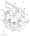
FIGS. 2A and 2B are views showing the chemical solution supply unit of FIG. 1 according to an embodiment of the present invention, respectively.
3 is a view showing the loader of FIG. 2B.
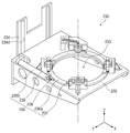
Figure 4 is a view showing the clamp of Figure 2b.
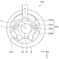
FIGS. 5A to 5C are views showing a process of operating the holder unit of FIG.
6A and 6B are views showing the coupler of FIG. 2B.
7A to 7E are diagrams showing a chemical liquid supply process in which the chemical liquid supply unit supplies chemical liquid to the substrate processing unit.
FIG. 8 is a view showing the chemical liquid supply unit of FIG. 1 according to an embodiment of the present invention.
FIG. 9A is a perspective view showing the clamp of FIG. 8, and FIGS. 9B and 9C are views showing the clamp of FIG. 8 clamping the container.
BRIEF DESCRIPTION OF THE DRAWINGS The advantages and features of the present invention, and how to accomplish them, will become apparent by reference to the embodiments described in detail below with reference to the accompanying drawings. The present invention may, however, be embodied in many different forms and should not be construed as being limited to the embodiments set forth herein. Rather, these embodiments are provided so that this disclosure will be thorough and complete, and will fully convey the concept of the invention to those skilled in the art. Is provided to fully convey the scope of the invention to those skilled in the art, and the invention is only defined by the scope of the claims. Like reference numerals refer to like elements throughout the specification.
The terminology used herein is for the purpose of illustrating embodiments and is not intended to be limiting of the present invention. In the present specification, the singular form includes plural forms unless otherwise specified in the specification. As used herein, the terms 'comprises' and / or 'comprising' mean that the stated element, step, operation and / or element does not imply the presence of one or more other elements, steps, operations and / Or additions. In addition, since they are in accordance with the preferred embodiment, the reference numerals presented in the order of description are not necessarily limited to the order. In addition, in this specification, when it is mentioned that a film is on another film or substrate, it means that it may be formed directly on another film or substrate, or a third film may be interposed therebetween.
In addition, the embodiments described herein will be described with reference to cross-sectional views and / or plan views, which are ideal illustrations of the present invention. In the drawings, the thicknesses of the films and regions are exaggerated for an effective description of the technical content. Accordingly, the embodiments of the present invention are not limited to the specific forms shown, but also include changes in the shapes that are generated according to the manufacturing process.
1 is a view showing a
The
2A and 2B are views showing the chemical
The
FIG. 3 is a view showing the
The
The
Fig. 4 is a view showing the
The
The
4 and 5A, the
4 and 5B, the
Referring to Figs. 4 and 5C, the driving
Referring again to FIG. 2B, a
The
The chemical
FIGS. 6A and 6B are views showing the
The
As shown in FIG. 6A, the
Referring again to FIG. 2B, a cleaning
Although not shown, the
7A to 7E are drawings showing a chemical liquid supply process in which the chemical
7A, when the
7B and 7C, the
7D, the
Referring to FIG. 7E, a
Thereafter, when the chemical liquid supply process is completed, the
According to the concept of the present invention, chemical fluid replacement and supply can be performed automatically, and an unmanned automation system can be realized. Further, the worker can be protected by reducing the environment in which the operator is exposed to the chemical liquid.
FIG. 8 is a view showing the chemical
Fig. 9A is a perspective view showing the
The
The
Referring again to FIG. 8, the
Although the
It is to be understood that the above-described embodiments are provided to facilitate understanding of the present invention, and do not limit the scope of the present invention, and it is to be understood that various modifications are possible within the scope of the present invention. It is to be understood that the technical scope of the present invention should be determined by the technical idea of the claims and the technical scope of protection of the present invention is not limited to the literary description of the claims, To the invention of the invention.
Claims (10)
And a chemical liquid supply unit for supplying the chemical liquid to the substrate processing unit,
The chemical liquid supply unit includes:
A loader for loading a container containing the drug solution;
A clamp for fixing the container loaded on the loader;
A chemical liquid supply line for supplying the chemical liquid to the substrate processing unit; And
And a coupler for coupling the chemical liquid supply line to the container.
The clamp comprises:
A holder for fixing the container; And
And a holder driving unit for driving the holder,
Wherein the holder driving unit moves the holder between a fixed position where the center axis of the container coincides with a center axis of the predetermined coupler and a standby position where the center axis of the container does not coincide with the center axis of the predetermined coupler, / RTI >
The coupler comprising:
A coupler coupling unit coupled to the injection port of the vessel; And
And a coupler driver for moving the coupler coupling in a direction perpendicular to the vessel.
Wherein the coupler is coupled to the clamp.
Wherein the chemical liquid supply unit further includes an opener for opening an inlet of the container.
Said opener comprising:
An opener engaging portion coupled to an inlet of the container; And
And an opener driving unit for moving the opener coupling unit in a direction perpendicular to the container.
Wherein the opener is coupled to one side of the coupler.
The chemical liquid supply unit further comprises a guide disposed along a direction parallel to the container,
Wherein the coupler and the opener are coupled to the guide.
Wherein the coupler further includes a tray for preventing the chemical liquid in the chemical liquid supply line from being discharged out of the chemical liquid supply line.
And the coupler is disposed at one end of the chemical liquid supply line.
Priority Applications (2)
| Application Number | Priority Date | Filing Date | Title |
|---|---|---|---|
| KR1020160019313A KR20170097833A (en) | 2016-02-18 | 2016-02-18 | Chemical supplying apparatus and substrate treating apparatus |
| US15/401,800 US9989855B2 (en) | 2016-02-18 | 2017-01-09 | Chemical supply unit capable of automatically replacing a canister and a substrate treatment apparatus having the same |
Applications Claiming Priority (1)
| Application Number | Priority Date | Filing Date | Title |
|---|---|---|---|
| KR1020160019313A KR20170097833A (en) | 2016-02-18 | 2016-02-18 | Chemical supplying apparatus and substrate treating apparatus |
Publications (1)
| Publication Number | Publication Date |
|---|---|
| KR20170097833A true KR20170097833A (en) | 2017-08-29 |
Family
ID=59629930
Family Applications (1)
| Application Number | Title | Priority Date | Filing Date |
|---|---|---|---|
| KR1020160019313A KR20170097833A (en) | 2016-02-18 | 2016-02-18 | Chemical supplying apparatus and substrate treating apparatus |
Country Status (2)
| Country | Link |
|---|---|
| US (1) | US9989855B2 (en) |
| KR (1) | KR20170097833A (en) |
Cited By (3)
| Publication number | Priority date | Publication date | Assignee | Title |
|---|---|---|---|---|
| US11322346B2 (en) | 2020-09-18 | 2022-05-03 | Samsung Electronics Co., Ltd. | Cleaning substrate method and method of processing substrate using the same |
| KR102434744B1 (en) * | 2021-11-18 | 2022-08-19 | 손백호 | Chemical discharge device with stopper opening and closing function |
| KR102603034B1 (en) * | 2023-07-03 | 2023-11-20 | (주)에스티글로벌 | Chemical Storage Container Management System for Semiconductor Process Using Short-Range Wireless Communication |
Families Citing this family (3)
| Publication number | Priority date | Publication date | Assignee | Title |
|---|---|---|---|---|
| US10943802B2 (en) * | 2018-07-31 | 2021-03-09 | Taiwan Semiconductor Manufacturing Co., Ltd. | Photoresist bottle container |
| US11029603B2 (en) * | 2018-09-28 | 2021-06-08 | Taiwan Semiconductor Manufacturing Co., Ltd. | Chemical replacement system |
| CN112113131A (en) * | 2020-08-07 | 2020-12-22 | 丁柱丹 | Chemical gas cylinder loading and unloading conveyer |
Family Cites Families (13)
| Publication number | Priority date | Publication date | Assignee | Title |
|---|---|---|---|---|
| US5102010A (en) * | 1988-02-16 | 1992-04-07 | Now Technologies, Inc. | Container and dispensing system for liquid chemicals |
| JPH0920359A (en) | 1995-07-05 | 1997-01-21 | Hitachi Ltd | Solution supplying device |
| KR20010053914A (en) | 1999-12-02 | 2001-07-02 | 윤종용 | Chemical transfer apparatus |
| JP3563014B2 (en) | 2000-06-26 | 2004-09-08 | 株式会社トップ | Discharge container |
| KR20070066627A (en) | 2005-12-22 | 2007-06-27 | 삼성전자주식회사 | Apparatus for opening/closing a chemical container |
| KR20090029393A (en) | 2007-09-18 | 2009-03-23 | 세메스 주식회사 | Controlling method for exchanging chemical |
| KR100938240B1 (en) | 2008-01-17 | 2010-01-22 | 세메스 주식회사 | Liquid supply device and controlling method thereof |
| KR101403510B1 (en) | 2013-01-25 | 2014-06-09 | 주식회사 디엠에스 | Apparatus for wet process |
| US10000331B2 (en) | 2013-08-08 | 2018-06-19 | Tokyo Electron Limited | Bottle change apparatus, substrate treatment apparatus, bottle change method, bottle cap, bottle cap change apparatus and bottle cap change method |
| TWI584351B (en) | 2013-10-08 | 2017-05-21 | Tokyo Electron Ltd | Liquid container exchange device, container-mounted module and exchange solution of chemical liquid container, substrate processing device |
| JP5987807B2 (en) | 2013-10-08 | 2016-09-07 | 東京エレクトロン株式会社 | Chemical container replacement device, container placement module, and chemical container replacement method |
| KR101517033B1 (en) | 2013-12-20 | 2015-05-04 | 주식회사 케이씨텍 | Chamical supply |
| KR101535870B1 (en) | 2014-04-29 | 2015-07-14 | 주식회사케리텍 | Chemical Supplying Apparatus for Spinner Process |
-
2016
- 2016-02-18 KR KR1020160019313A patent/KR20170097833A/en unknown
-
2017
- 2017-01-09 US US15/401,800 patent/US9989855B2/en not_active Expired - Fee Related
Cited By (3)
| Publication number | Priority date | Publication date | Assignee | Title |
|---|---|---|---|---|
| US11322346B2 (en) | 2020-09-18 | 2022-05-03 | Samsung Electronics Co., Ltd. | Cleaning substrate method and method of processing substrate using the same |
| KR102434744B1 (en) * | 2021-11-18 | 2022-08-19 | 손백호 | Chemical discharge device with stopper opening and closing function |
| KR102603034B1 (en) * | 2023-07-03 | 2023-11-20 | (주)에스티글로벌 | Chemical Storage Container Management System for Semiconductor Process Using Short-Range Wireless Communication |
Also Published As
| Publication number | Publication date |
|---|---|
| US20170242340A1 (en) | 2017-08-24 |
| US9989855B2 (en) | 2018-06-05 |
Similar Documents
| Publication | Publication Date | Title |
|---|---|---|
| KR20170097833A (en) | Chemical supplying apparatus and substrate treating apparatus | |
| JP5256064B2 (en) | Solder supply device and printing device | |
| JP4493605B2 (en) | Manifold assembly | |
| JP6744780B2 (en) | Resin molding equipment | |
| US20070034332A1 (en) | Apparatus and method for fabricating bonded substrate | |
| TWI489575B (en) | Substrate inverting apparatus, substrate handling method, and substrate processing apparatus | |
| JP2002229044A (en) | Apparatus for manufacturing bonded substrate | |
| JP4596619B2 (en) | Substrate processing system, method for transferring substrate in system, robot blade for substrate processing system, and robot for substrate processing system | |
| JP3626610B2 (en) | Processing apparatus and processing method | |
| JP2005218899A (en) | Coating device and display device manufacturing apparatus provided with this | |
| TWI487577B (en) | Methods for mixed acid cleaning of showerhead electrodes | |
| TWI379132B (en) | ||
| EP0032954A1 (en) | A Cassette-Type Automatic Hollow Roller Mounting And Demounting Apparatus | |
| TW201738990A (en) | Treating apparatus | |
| KR100462374B1 (en) | Device and method for attaching polarizing plates | |
| KR100622410B1 (en) | Tft-lcd module assembly assembling apparatus and tft-lcd module assembly assembling method using the same | |
| US4340450A (en) | Method for plating rollers and apparatus for mounting rollers utilized in the method | |
| KR100521607B1 (en) | Paste application apparatus | |
| US20230339630A1 (en) | Filling apparatus | |
| KR20160050391A (en) | Lamination apparatus | |
| KR102252623B1 (en) | Articulated robot type protective film peeling apparatus | |
| TW574575B (en) | Substrate assembling method and assembling apparatus | |
| TWI684659B (en) | Film formation apparatus | |
| JP3778002B2 (en) | Dispensing device | |
| JP2003023060A (en) | Suspended type substrate holding apparatus and apparatus for manufacturing liquid crystal panel |