KR20170088931A - System and method for modifying a service-specific data plane configuration - Google Patents
System and method for modifying a service-specific data plane configuration Download PDFInfo
- Publication number
- KR20170088931A KR20170088931A KR1020177017144A KR20177017144A KR20170088931A KR 20170088931 A KR20170088931 A KR 20170088931A KR 1020177017144 A KR1020177017144 A KR 1020177017144A KR 20177017144 A KR20177017144 A KR 20177017144A KR 20170088931 A KR20170088931 A KR 20170088931A
- Authority
- KR
- South Korea
- Prior art keywords
- logical
- protocol
- configuration
- logical link
- traffic
- Prior art date
Links
- 238000000034 method Methods 0.000 title claims abstract description 123
- 230000008859 change Effects 0.000 claims abstract description 68
- 230000006978 adaptation Effects 0.000 claims abstract description 67
- 238000013468 resource allocation Methods 0.000 claims abstract description 43
- 238000007493 shaping process Methods 0.000 claims description 39
- 230000006870 function Effects 0.000 claims description 30
- 238000012913 prioritisation Methods 0.000 claims description 21
- 238000005259 measurement Methods 0.000 claims description 18
- 230000003213 activating effect Effects 0.000 claims description 17
- 230000002776 aggregation Effects 0.000 claims description 17
- 238000004220 aggregation Methods 0.000 claims description 17
- 230000003044 adaptive effect Effects 0.000 claims description 14
- 230000004048 modification Effects 0.000 claims description 13
- 238000012986 modification Methods 0.000 claims description 13
- 238000012217 deletion Methods 0.000 claims description 8
- 230000037430 deletion Effects 0.000 claims description 8
- 230000009849 deactivation Effects 0.000 claims description 6
- 238000003860 storage Methods 0.000 claims description 6
- 230000004913 activation Effects 0.000 claims description 5
- 230000004075 alteration Effects 0.000 claims description 4
- 230000009467 reduction Effects 0.000 claims description 4
- 230000001052 transient effect Effects 0.000 claims description 3
- 230000003247 decreasing effect Effects 0.000 claims 1
- 238000012544 monitoring process Methods 0.000 description 77
- 208000027744 congestion Diseases 0.000 description 55
- 238000012545 processing Methods 0.000 description 32
- 238000010586 diagram Methods 0.000 description 19
- 230000006854 communication Effects 0.000 description 12
- 238000004891 communication Methods 0.000 description 12
- 230000008093 supporting effect Effects 0.000 description 10
- 230000008569 process Effects 0.000 description 9
- 238000005516 engineering process Methods 0.000 description 7
- 238000005457 optimization Methods 0.000 description 7
- 230000011664 signaling Effects 0.000 description 7
- 230000015556 catabolic process Effects 0.000 description 6
- 238000006731 degradation reaction Methods 0.000 description 6
- 230000009471 action Effects 0.000 description 5
- 238000007726 management method Methods 0.000 description 5
- 230000007774 longterm Effects 0.000 description 4
- 230000000116 mitigating effect Effects 0.000 description 4
- 230000008447 perception Effects 0.000 description 4
- 230000005540 biological transmission Effects 0.000 description 3
- 238000001914 filtration Methods 0.000 description 3
- 230000008901 benefit Effects 0.000 description 2
- 230000007613 environmental effect Effects 0.000 description 2
- 230000006855 networking Effects 0.000 description 2
- 230000000737 periodic effect Effects 0.000 description 2
- 238000012546 transfer Methods 0.000 description 2
- 230000001960 triggered effect Effects 0.000 description 2
- 238000013459 approach Methods 0.000 description 1
- 238000003491 array Methods 0.000 description 1
- 230000009286 beneficial effect Effects 0.000 description 1
- 230000007175 bidirectional communication Effects 0.000 description 1
- 230000001413 cellular effect Effects 0.000 description 1
- 230000006835 compression Effects 0.000 description 1
- 238000007906 compression Methods 0.000 description 1
- 238000009826 distribution Methods 0.000 description 1
- 238000013467 fragmentation Methods 0.000 description 1
- 238000006062 fragmentation reaction Methods 0.000 description 1
- 230000036541 health Effects 0.000 description 1
- RGNPBRKPHBKNKX-UHFFFAOYSA-N hexaflumuron Chemical compound C1=C(Cl)C(OC(F)(F)C(F)F)=C(Cl)C=C1NC(=O)NC(=O)C1=C(F)C=CC=C1F RGNPBRKPHBKNKX-UHFFFAOYSA-N 0.000 description 1
- 230000001976 improved effect Effects 0.000 description 1
- 238000009434 installation Methods 0.000 description 1
- 230000010354 integration Effects 0.000 description 1
- 238000004519 manufacturing process Methods 0.000 description 1
- 238000013507 mapping Methods 0.000 description 1
- 230000007246 mechanism Effects 0.000 description 1
- 125000001400 nonyl group Chemical group [H]C([*])([H])C([H])([H])C([H])([H])C([H])([H])C([H])([H])C([H])([H])C([H])([H])C([H])([H])C([H])([H])[H] 0.000 description 1
- 239000013307 optical fiber Substances 0.000 description 1
- 239000002957 persistent organic pollutant Substances 0.000 description 1
- 238000007781 pre-processing Methods 0.000 description 1
- 238000011084 recovery Methods 0.000 description 1
- 238000012384 transportation and delivery Methods 0.000 description 1
- 238000011144 upstream manufacturing Methods 0.000 description 1
Images


Classifications
-
- H—ELECTRICITY
- H04—ELECTRIC COMMUNICATION TECHNIQUE
- H04W—WIRELESS COMMUNICATION NETWORKS
- H04W24/00—Supervisory, monitoring or testing arrangements
- H04W24/02—Arrangements for optimising operational condition
-
- H—ELECTRICITY
- H04—ELECTRIC COMMUNICATION TECHNIQUE
- H04L—TRANSMISSION OF DIGITAL INFORMATION, e.g. TELEGRAPHIC COMMUNICATION
- H04L41/00—Arrangements for maintenance, administration or management of data switching networks, e.g. of packet switching networks
- H04L41/08—Configuration management of networks or network elements
- H04L41/0803—Configuration setting
- H04L41/0813—Configuration setting characterised by the conditions triggering a change of settings
- H04L41/0816—Configuration setting characterised by the conditions triggering a change of settings the condition being an adaptation, e.g. in response to network events
-
- H—ELECTRICITY
- H04—ELECTRIC COMMUNICATION TECHNIQUE
- H04L—TRANSMISSION OF DIGITAL INFORMATION, e.g. TELEGRAPHIC COMMUNICATION
- H04L41/00—Arrangements for maintenance, administration or management of data switching networks, e.g. of packet switching networks
- H04L41/08—Configuration management of networks or network elements
- H04L41/0895—Configuration of virtualised networks or elements, e.g. virtualised network function or OpenFlow elements
-
- H—ELECTRICITY
- H04—ELECTRIC COMMUNICATION TECHNIQUE
- H04L—TRANSMISSION OF DIGITAL INFORMATION, e.g. TELEGRAPHIC COMMUNICATION
- H04L41/00—Arrangements for maintenance, administration or management of data switching networks, e.g. of packet switching networks
- H04L41/08—Configuration management of networks or network elements
- H04L41/0896—Bandwidth or capacity management, i.e. automatically increasing or decreasing capacities
- H04L41/0897—Bandwidth or capacity management, i.e. automatically increasing or decreasing capacities by horizontal or vertical scaling of resources, or by migrating entities, e.g. virtual resources or entities
-
- H—ELECTRICITY
- H04—ELECTRIC COMMUNICATION TECHNIQUE
- H04L—TRANSMISSION OF DIGITAL INFORMATION, e.g. TELEGRAPHIC COMMUNICATION
- H04L41/00—Arrangements for maintenance, administration or management of data switching networks, e.g. of packet switching networks
- H04L41/40—Arrangements for maintenance, administration or management of data switching networks, e.g. of packet switching networks using virtualisation of network functions or resources, e.g. SDN or NFV entities
-
- H—ELECTRICITY
- H04—ELECTRIC COMMUNICATION TECHNIQUE
- H04L—TRANSMISSION OF DIGITAL INFORMATION, e.g. TELEGRAPHIC COMMUNICATION
- H04L41/00—Arrangements for maintenance, administration or management of data switching networks, e.g. of packet switching networks
- H04L41/50—Network service management, e.g. ensuring proper service fulfilment according to agreements
- H04L41/5003—Managing SLA; Interaction between SLA and QoS
- H04L41/5019—Ensuring fulfilment of SLA
- H04L41/5025—Ensuring fulfilment of SLA by proactively reacting to service quality change, e.g. by reconfiguration after service quality degradation or upgrade
-
- H—ELECTRICITY
- H04—ELECTRIC COMMUNICATION TECHNIQUE
- H04L—TRANSMISSION OF DIGITAL INFORMATION, e.g. TELEGRAPHIC COMMUNICATION
- H04L43/00—Arrangements for monitoring or testing data switching networks
- H04L43/08—Monitoring or testing based on specific metrics, e.g. QoS, energy consumption or environmental parameters
-
- H—ELECTRICITY
- H04—ELECTRIC COMMUNICATION TECHNIQUE
- H04L—TRANSMISSION OF DIGITAL INFORMATION, e.g. TELEGRAPHIC COMMUNICATION
- H04L43/00—Arrangements for monitoring or testing data switching networks
- H04L43/20—Arrangements for monitoring or testing data switching networks the monitoring system or the monitored elements being virtualised, abstracted or software-defined entities, e.g. SDN or NFV
-
- H—ELECTRICITY
- H04—ELECTRIC COMMUNICATION TECHNIQUE
- H04W—WIRELESS COMMUNICATION NETWORKS
- H04W28/00—Network traffic management; Network resource management
- H04W28/02—Traffic management, e.g. flow control or congestion control
- H04W28/08—Load balancing or load distribution
- H04W28/084—Load balancing or load distribution among network function virtualisation [NFV] entities; among edge computing entities, e.g. multi-access edge computing
-
- H04W4/005—
-
- H—ELECTRICITY
- H04—ELECTRIC COMMUNICATION TECHNIQUE
- H04W—WIRELESS COMMUNICATION NETWORKS
- H04W4/00—Services specially adapted for wireless communication networks; Facilities therefor
- H04W4/70—Services for machine-to-machine communication [M2M] or machine type communication [MTC]
-
- H—ELECTRICITY
- H04—ELECTRIC COMMUNICATION TECHNIQUE
- H04W—WIRELESS COMMUNICATION NETWORKS
- H04W4/00—Services specially adapted for wireless communication networks; Facilities therefor
- H04W4/80—Services using short range communication, e.g. near-field communication [NFC], radio-frequency identification [RFID] or low energy communication
-
- H—ELECTRICITY
- H04—ELECTRIC COMMUNICATION TECHNIQUE
- H04L—TRANSMISSION OF DIGITAL INFORMATION, e.g. TELEGRAPHIC COMMUNICATION
- H04L43/00—Arrangements for monitoring or testing data switching networks
- H04L43/08—Monitoring or testing based on specific metrics, e.g. QoS, energy consumption or environmental parameters
- H04L43/0852—Delays
-
- H—ELECTRICITY
- H04—ELECTRIC COMMUNICATION TECHNIQUE
- H04L—TRANSMISSION OF DIGITAL INFORMATION, e.g. TELEGRAPHIC COMMUNICATION
- H04L43/00—Arrangements for monitoring or testing data switching networks
- H04L43/08—Monitoring or testing based on specific metrics, e.g. QoS, energy consumption or environmental parameters
- H04L43/0876—Network utilisation, e.g. volume of load or congestion level
- H04L43/0888—Throughput
-
- H—ELECTRICITY
- H04—ELECTRIC COMMUNICATION TECHNIQUE
- H04L—TRANSMISSION OF DIGITAL INFORMATION, e.g. TELEGRAPHIC COMMUNICATION
- H04L47/00—Traffic control in data switching networks
- H04L47/10—Flow control; Congestion control
- H04L47/12—Avoiding congestion; Recovering from congestion
-
- H—ELECTRICITY
- H04—ELECTRIC COMMUNICATION TECHNIQUE
- H04W—WIRELESS COMMUNICATION NETWORKS
- H04W28/00—Network traffic management; Network resource management
- H04W28/02—Traffic management, e.g. flow control or congestion control
- H04W28/0289—Congestion control
-
- H—ELECTRICITY
- H04—ELECTRIC COMMUNICATION TECHNIQUE
- H04W—WIRELESS COMMUNICATION NETWORKS
- H04W28/00—Network traffic management; Network resource management
- H04W28/16—Central resource management; Negotiation of resources or communication parameters, e.g. negotiating bandwidth or QoS [Quality of Service]
- H04W28/18—Negotiating wireless communication parameters
-
- Y—GENERAL TAGGING OF NEW TECHNOLOGICAL DEVELOPMENTS; GENERAL TAGGING OF CROSS-SECTIONAL TECHNOLOGIES SPANNING OVER SEVERAL SECTIONS OF THE IPC; TECHNICAL SUBJECTS COVERED BY FORMER USPC CROSS-REFERENCE ART COLLECTIONS [XRACs] AND DIGESTS
- Y04—INFORMATION OR COMMUNICATION TECHNOLOGIES HAVING AN IMPACT ON OTHER TECHNOLOGY AREAS
- Y04S—SYSTEMS INTEGRATING TECHNOLOGIES RELATED TO POWER NETWORK OPERATION, COMMUNICATION OR INFORMATION TECHNOLOGIES FOR IMPROVING THE ELECTRICAL POWER GENERATION, TRANSMISSION, DISTRIBUTION, MANAGEMENT OR USAGE, i.e. SMART GRIDS
- Y04S40/00—Systems for electrical power generation, transmission, distribution or end-user application management characterised by the use of communication or information technologies, or communication or information technology specific aspects supporting them
Abstract
네트워크 적응 방법은, 가상 네트워크의 적응 코디네이터가, 가상 네트워크 내에 위치된 성능 체크포인트에서 생성된 성능 측정치를 수신하는 단계를 포함한다. 상기 방법은 또한 적응 코디네이터가, 가상 네트워크의 서비스 특정 구성의 제1 업데이트를 생성하는 단계를 포함한다. 제1 업데이트는 성능 체크포인트 구성의 변경, 또는 가상 네트워크 기능(virtual network function, VNF) 구성의 변경, 또는 프로토콜 구성(protocol configuration)의 변경, 또는 자원 할당 입력의 변경, 또는 논리 그래프의 변경 중 적어도 하나를 포함한다. 서비스 특정 구성은 서비스 특정 데이터 평면 논리 토폴로지에 따라 가상 네트워크의 복수의 논리 링크 및 복수의 논리 노드의 구성을 포함한다.The network adaptation method includes the step of the adaptation coordinator of the virtual network receiving the performance measure generated at the performance checkpoint located in the virtual network. The method also includes an adaptation coordinator generating a first update of a service specific configuration of the virtual network. The first update may include at least one of a change in a performance checkpoint configuration or a change in a virtual network function (VNF) configuration, a change in a protocol configuration, a change in a resource allocation input, One. The service specific configuration comprises a plurality of logical links of the virtual network and a plurality of logical nodes according to a service specific data plane logical topology.
Description
본 출원은 2014년 11월 21일에 미국 특허청에 가출원된 미국 출원 번호 62/083,033의 우선권을 주장하며, 이 출원은 여기에 참조 문헌으로 포함된다.This application claims priority to U.S. Serial No. 62 / 083,033, filed on November 21, 2014, which is hereby incorporated by reference.
본 발명은 일반적으로 데이터 평면 구성을 변경하기 위한 시스템 및 방법에 관한 것이고, 특정 실시예에서, 서비스 특정 데이터 평면 구성을 변경하기 위한 시스템 및 방법에 관한 것이다.The present invention generally relates to systems and methods for altering data plane configurations, and in particular embodiments, systems and methods for altering service specific data plane configurations.
원격통신 네트워크는 비용 효율을 유지하거나 증가시키면서, 더 높은 데이터 속도와 서비스 품질을 제공하기 위한 향상된 기능 및 기능을 갖춘 신기술을 통합함으로써 수익 창출을 개선하기 위해 끊임없이 진화하고 있다. 따라서 네트워크 운영자는 M2M(machine-to-machine) 장기간 모니터링 및 제어 서비스를 포함하는, 다양한 새로운 수익 창출 서비스를 고려해왔다. M2M 서비스는, 예를 들어, 트래픽 모니터링, 차량 관리, 스마트 미터링, 환경 모니터링, 산업 모니터링, 및 제어 등을 포함할 수 있다. M2M 장치의 개수는 더 많은 연결 장치가 소비자에게 제공되고 센서 네트워크와 같은 M2M 기술을 더 많은 산업이 채택함에 따라 빠르게 증가할 것으로 예상된다.Telecommunication networks are constantly evolving to improve revenue generation by integrating new technologies with enhanced features and functionality to provide higher data rates and quality of service while maintaining or increasing cost efficiency. Thus, network operators have considered a variety of new revenue generating services, including machine-to-machine (M2M) long-term monitoring and control services. The M2M service may include, for example, traffic monitoring, vehicle management, smart metering, environmental monitoring, industrial monitoring, and control. The number of M2M devices is expected to increase rapidly as more connected devices are offered to consumers and more industries adopt M2M technology such as sensor networks.
본 발명의 제1 실시예에 따르면, 네트워크 적응 방법이 제공된다. 상기 방법은 가상 네트워크의 적응 코디네이터가, 가상 네트워크 내에 위치된 성능 체크포인트에서 생성된 성능 측정치를 수신하는 단계를 포함한다. 상기 방법은 또한 적응 코디네이터가 가상 네트워크의 서비스 특정 구성의 제1 업데이트를 생성하는 단계를 포함한다. 제1 업데이트는 성능 체크포인트 구성의 변경, 또는 가상 네트워크 기능(VNF) 구성의 변경, 또는 프로토콜 구성의 수정, 또는 자원 할당 입력의 변경, 또는 논리 그래프의 변경 중 적어도 하나를 포함한다. 서비스 특정 구성은 서비스 특정 데이터 평면 논리 토폴로지에 따라 가상 네트워크의 복수의 논리 노드 및 복수의 논리 링크의 구성을 포함한다.According to a first embodiment of the present invention, a network adaptation method is provided. The method includes an adaptation coordinator of a virtual network receiving a performance measure generated at a performance checkpoint located in a virtual network. The method also includes an adaptation coordinator generating a first update of a service specific configuration of the virtual network. The first update includes at least one of a change in a performance checkpoint configuration, a change in a virtual network function (VNF) configuration, a change in a protocol configuration, a change in a resource allocation input, or a change in a logical graph. The service specific configuration includes a plurality of logical nodes of the virtual network and a plurality of logical links in accordance with the service specific data plane logical topology.
본 발명의 제2 실시 예에 따르면, 네트워크 적응 방법이 제공된다. 상기 방법은 가상 네트워크에 위치한 성능 체크포인트에서 생성된 성능 측정치를 수신하는 단계를 포함한다. 상기 방법은 또한 가상 네트워크의 논리 그래프를 변경하는 것을 포함하지 않는 제1 구성 업데이트 동안 성능 측정치에 따라 가상 네트워크의 서비스 특정 구성을 변경하는 단계를 포함한다. 서비스 특정 구성을 변경하는 것은 성능 체크포인트 구성을 변경하는 것, 또는 VNF 구성을 변경하는 것, 프로토콜 구성을 변경하는 것, 또는 자원 할당 입력을 변경하는 것 중 적어도 하나를 포함한다. 서비스 특정 구성은 가상 네트워크의 복수의 논리 노드 및 복수의 논리 링크의 구성을 포함한다.According to a second embodiment of the present invention, a network adaptation method is provided. The method includes receiving a performance measure generated at a performance checkpoint located in a virtual network. The method also includes modifying a service specific configuration of the virtual network according to performance measurements during a first configuration update that does not involve modifying the logical graph of the virtual network. Changing the service specific configuration includes at least one of changing the performance checkpoint configuration, changing the VNF configuration, changing the protocol configuration, or changing the resource allocation input. The service specific configuration includes the configuration of a plurality of logical nodes and a plurality of logical links of the virtual network.
본 발명의 제3 실시 예에 따르면, 적응 코디네이터가 제공된다. 적응 코디네이터는 프로세서 및 프로세서에 의한 실행을 위한 프로그래밍을 저장하는 비-일시적 컴퓨터 판독 가능 저장 매체를 포함한다. 프로그래밍은 가상 네트워크에 위치한 성능 체크포인트에서 생성된 성능 측정치를 수신하고 가상 네트워크의 서비스 특정 구성의 제1 업데이트를 생성하기 위한 명령을 포함한다. 제1 업데이트는 성능 체크포인트 구성의 변경, 또는 VNF 구성의 변경, 또는 프로토콜 구성의 변경, 또는 자원 할당 입력의 변경, 또는 논리 그래프의 변경 중 적어도 하나를 포함한다. 서비스 특정 구성은 서비스 특정 데이터 평면 논리 토폴로지에 따라 가상 네트워크의 복수의 논리 노드 및 가상 네트워크의 복수의 논리 링크의 구성을 포함한다.According to a third embodiment of the present invention, an adaptive coordinator is provided. The adaptation coordinator includes a processor and a non-transitory computer readable storage medium that stores programming for execution by the processor. The programming includes receiving performance metrics generated at a performance checkpoint located in the virtual network and generating instructions to generate a first update of the service specific configuration of the virtual network. The first update includes at least one of a change in the performance checkpoint configuration, a change in the VNF configuration, a change in the protocol configuration, a change in the resource allocation input, or a change in the logic graph. The service specific configuration comprises a plurality of logical nodes of the virtual network and a plurality of logical links of the virtual network according to the service specific data plane logical topology.
본 발명과, 그 이점에 대한 완벽한 이해를 위해서, 첨부된 도면과 관련하여 취해진 아래 설명이 참조된다.
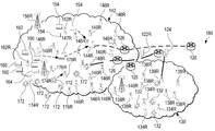
도 1은 본 발명의 실시예에 따른, M2M 트랜잭션을 지원하는 정보-중심 맞춤형 가상 네트워크 아키텍처를 위한 네트워크를 도시하는 블록도이다;
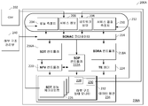
도 2a는 본 발명의 실시예에 따른, 서비스 지향 네트워크 자동 생성(SONAC)이 가능한 네트워크를 도시하는 블록도이다;
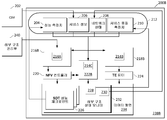
도 2b는 본 발명의 실시예에 따른, 변경된 네트워크 제어 시스템을 포함하는 대안적 SONAC-가능 네트워크를 도시하는 블록도이다;
도 2c는 본 발명의 실시예에 따른, 가상 네트워크 데이터 평면 내에서 구현될 수 있는 서비스 특정 데이터 평면 논리 토폴로지(SSDPLT)를 도시하는 블록도이다;
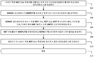
도 3은 본 발명의 실시예에 따른, SONAC-가능 네트워크에 의해 지원되는 특정 서비스에 관련된 동적 적응을 수행하는 방법을 도시하는 흐름도이다;
도 4a는 본 발명의 실시예에 따른, 서비스 특정 트래픽 혼잡을 갖는 SONAC-가능 네트워크의 서비스를 제공하는 방법을 도시하는 흐름도이다;
도 4b는 본 발명의 실시예에 따른, 도 2a의 네트워크 제어 시스템을 사용하는 가상 네트워크 서비스 인스턴스화 방법을 도시하는 흐름도이다;
도 4c는 본 발명의 실시예에 따른, 도 2a의 네트워크 제어 시스템을 사용하는 서비스 특정 트래픽 혼잡을 진단하고 완화하는 방법을 도시하는 흐름도이다;
도 4d는 본 발명의 실시예에 따른, 도 2a의 네트워크 제어 시스템을 사용하는 라우터-관련 트래픽 혼잡을 완화하기 위한 방법을 도시하는 흐름도이다;
도 4e는 본 발명의 실시예에 따른, 도 2a의 네트워크 제어 시스템을 사용하는 링크-관련 트래픽 혼잡을 완화하기 위한 방법을 도시하는 흐름도이다;
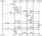
도 5a는 본 발명의 실시예에 따른, 도 2a의 네트워크 제어 시스템을 사용하는 가상 네트워크 서비스 인스턴스화를 위한 신호를 도시하는 신호도이다;
도 5b는 본 발명의 실시예에 따른, 라우터-관련 혼잡 동안에 도 2a의 가상 네트워크의 구성의 업데이트를 위한 신호를 도시하는 신호도이다;
도 5c는 본 발명의 실시예에 따른, 링크-관련 혼잡 동안에 도 2a의 가상 네트워크의 구성의 업데이트를 위한 신호를 도시하는 신호도이다;
도 6a는 본 발명의 실시예에 따른, 도 2b의 네트워크 제어 시스템을 사용하는 가상 네트워크 서비스 인스턴스화를 위한 신호를 도시하는 신호도이다;
도 6b는 본 발명의 실시예에 따른, 라우터-관련 혼잡 동안에 도 2b의 가상 네트워크의 구성의 업데이트를 위한 신호를 도시하는 신호도이다;
도 6c는 본 발명의 실시예에 따른, 링크-관련 혼잡 동안에 도 2b의 가상 네트워크의 구성의 업데이트를 위한 신호를 도시하는 신호도이다;
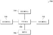
도 7a는 본 발명의 실시예에 따른, 호스트 장치 내에 설치될 수 있는, 여기서 설명된 방법을 수행하기 위한 처리 시스템의 블록도를 도시한다; 및
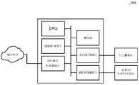
도 7b는 본 발명의 실시예에 따른, 원격통신 네트워크를 통해서 시그널링을 전송하고 수신하도록 적응된 트랜시버의 블록도를 도시한다.BRIEF DESCRIPTION OF THE DRAWINGS For a complete understanding of the present invention, and the advantages thereof, reference is made to the following description taken in conjunction with the accompanying drawings, in which: FIG.
1 is a block diagram illustrating a network for an information-centric customized virtual network architecture that supports M2M transactions, in accordance with an embodiment of the present invention;
2A is a block diagram illustrating a service-enabled network automatic generation (SONAC) enabled network, in accordance with an embodiment of the present invention;
Figure 2B is a block diagram illustrating an alternative SONAC-capable network including a modified network control system, in accordance with an embodiment of the present invention;
2C is a block diagram illustrating a service specific data plane logical topology (SSDPLT) that may be implemented within a virtual network data plane, in accordance with an embodiment of the present invention;
3 is a flow diagram illustrating a method for performing dynamic adaptation related to a particular service supported by a SONAC-enabled network, in accordance with an embodiment of the present invention;
4A is a flow diagram illustrating a method of providing a service of a SONAC-capable network with service specific traffic congestion, in accordance with an embodiment of the present invention;
4B is a flow diagram illustrating a method for instantiating a virtual network service using the network control system of FIG. 2A, in accordance with an embodiment of the present invention;
4C is a flowchart illustrating a method for diagnosing and mitigating service specific traffic congestion using the network control system of FIG. 2A, in accordance with an embodiment of the present invention;
4D is a flow diagram illustrating a method for mitigating router-related traffic congestion using the network control system of FIG. 2A, in accordance with an embodiment of the present invention;
4E is a flow diagram illustrating a method for mitigating link-related traffic congestion using the network control system of FIG. 2A, in accordance with an embodiment of the present invention;
5A is a signal diagram illustrating a signal for instantiating a virtual network service using the network control system of FIG. 2A according to an embodiment of the present invention; FIG.
Figure 5B is a signal diagram illustrating a signal for updating the configuration of the virtual network of Figure 2A during router-related congestion, in accordance with an embodiment of the present invention;
5C is a signal diagram illustrating a signal for updating the configuration of the virtual network of FIG. 2A during link-related congestion, in accordance with an embodiment of the present invention;
6A is a signal diagram illustrating a signal for virtual network service instantiation using the network control system of FIG. 2B, in accordance with an embodiment of the present invention; FIG.
FIG. 6B is a signal diagram illustrating a signal for updating the configuration of the virtual network of FIG. 2B during router-related congestion, in accordance with an embodiment of the present invention;
Figure 6C is a signal diagram illustrating a signal for updating the configuration of the virtual network of Figure 2B during link-related congestion, in accordance with an embodiment of the present invention;
7A illustrates a block diagram of a processing system for performing the method described herein, which may be installed within a host device, in accordance with an embodiment of the present invention; And
7B illustrates a block diagram of a transceiver adapted to transmit and receive signaling over a telecommunication network, in accordance with an embodiment of the present invention.
현재 바람직한 실시예의 구조, 제조 및 사용이 아래에서 상세히 논의된다. 그러나, 본 발명은 다양한 특정 상황에서 구현될 수 있는 많은 적용 가능한 발명 개념을 제공함이 이해되어야 한다. 논의된 특정 실시예는 단지 본 발명을 제조하고 사용하기 위한 특정 방법의 예시이며, 본 발명의 범위를 제한하지 않는다.The structure, manufacture and use of currently preferred embodiments are discussed in detail below. It should be understood, however, that the present invention provides many applicable inventive concepts that may be implemented in a variety of specific contexts. The specific embodiments discussed are merely illustrative of specific methods for making and using the invention and are not intended to limit the scope of the invention.
다양한 실시 예들에서, 유선 및/또는 무선 노드의 네트워크는 네트워크 기능 가상화(network function virtualization, NFV) 하부 구조(NFV Infrastructure, NFVI)를 사용한다. NFVI를 사용함으로써, 네크워크 기능이 기본적인 하드웨어 인프라가 가용한 다양한 서로 다른 위치에서 인스턴스화 될 수 있다. 네트워크 기능은 필요한 지점에, 필요로 할 때 배치될 수 있고, 네트워크의 필요에 따라 해체되거나 이동될 수 있다. NFV 하부 구조에 의해 지원될 수 있는 가상 네트워크 기능(Virtual Network Functions, VNF)은, 예를 들어, 플로우 제어를 위한 기능(예를 들어, 정렬 및 레이트 매칭(rate matching) 포함), 신뢰성(예를 들어, 데이터 손실 식별, 데이터 손실 지시, 및 데이터 복구 포함), 보안성(예를 들어, 단대단(end-to-end) 또는 네트워크 보안 포함), 데이터 전송, 고장(out-of-order) 제어(예를 들어, 패킷 순서 번호 포함), 단편화(fragmentation)/재조립(reassembly), 압축(compression), 혼잡(congestion), 오류 제어(error control), 명명된 콘텐츠 전달(예를 들어, 콘텐츠 관심 저장소, 콘텐츠 소유자 식별, 콘텐츠 데이터 블록 캐싱, 콘텐츠 식별 및 콘텐츠 보안 검증 포함), 데이터 집성(data aggregation)(예를 들어, 역방향 멀티캐스트 집성), 데이터 홀딩(data holding)(예를 들어, 지연-허용 네트워킹 기능 및 재전송), 및 다른 기능들을 포함할 수 있다. 종단 노드(end node) 또는 경계 노드(edge node)에서 인스턴스화 된 몇몇 VNF는 네트워크를 통과하는 경로에서 단대단 기능인 기능을 수행할 수 있다. 예를 들어, 신뢰성 기능을 수행하기 위한 몇몇 VNF는 네트워크 경로를 따라 다수의 노드를 통해 한 쌍의 노드 및/또는 다중 링크를 연결하는 링크 내에서 인스턴스화 될 수 있다. 더 나아가, 일부 VNF는 서로 다른 레벨의 복잡도 또는 증가된 기능(예를 들어, 보안 기능)으로 작동하도록 구성될 수 있다. VNF의 사용은 이전에는 분산된 하드웨어 자원이었던 기능을 가상화, 즉 소프트웨어로 정의될 수 있게 함으로써 네트워크의 기능 요구 사항을 탄력적으로 지원할 수 있는 능력을 제공하는 가상화(virtualization)의 한 가지 예시이다. 예를 들어 VNF를 지원하는 기본적인 하드웨어 자원이 모두 물리적으로 동일 위치에 있지 않거나 개별 물리적 장치의 구성 리소스 중 일부만 포함하는 경우에도 VNF는 단일 자원 엔티티(resource entity)로 가상화될 수 있다.In various embodiments, the network of wired and / or wireless nodes uses a network function virtualization (NFV) infrastructure (NFVI Infrastructure, NFVI). By using NFVI, network functions can be instantiated at various different locations where the underlying hardware infrastructure is available. The network functions can be deployed at the required point, as needed, and can be disassembled or moved as needed by the network. Virtual Network Functions (VNF) that can be supported by the NFV infrastructure include, for example, functions for flow control (e.g., including sorting and rate matching), reliability (Eg, including end-to-end or network security), data transfer, out-of-order control (including data loss identification, data loss indication, and data recovery) (E.g., including packet sequence numbers), fragmentation / reassembly, compression, congestion, error control, named content delivery (e.g., (E. G., Delay-data aggregation (e. G., Reverse-multicast aggregation), data holding (e. G., Delay- Allowed networking capabilities and retransmission), and It may include other features. Some VNFs instantiated at an end node or an edge node can perform an end-to-end function in a path through the network. For example, some VNFs for performing a trusted function may be instantiated within a link connecting a pair of nodes and / or multiple links across multiple nodes along a network path. Further, some VNFs may be configured to operate at different levels of complexity or increased functionality (e.g., security functions). The use of VNF is one example of virtualization that provides the ability to flexibly support network functional requirements by allowing functions that were previously distributed hardware resources to be defined as virtualization, or software. For example, a VNF can be virtualized as a single resource entity even if all of the underlying hardware resources supporting the VNF are not physically co-located or contain only a fraction of the configuration resources of the individual physical devices.
다양한 실시예는 본 개시에서 가상 네트워크로 지칭되는 이러한 소프트웨어-정의 엔티티 중 하나를 포함하는데, 이는, 예를 들어, M2M 서비스와 같은 특정 서비스를 지원하기 위해 사용되는 가상화된 자원들의 집합이다. 다양한 실시예에서, M2M 트래픽은 성상의(star-like) 상향링크 통신 패턴에 의해 지배되고, 여기서 많은 수의 머신(트래픽 소스)은 더 적은 개수의 트래픽 싱크(traffic sink)를 보고한다. M2M 통신은 싱크가 소스를 질의하는 풀 모드(pull mode)와 소스가 사전에 싱크에게 데이터를 송신하는 푸시 모드(push mode)와 같은 서로 다른 모드에서 발생할 수 있다. 푸시 모드는 시간-중심(time-driven) 또는 이벤트-중심(event-driven)일 수 있다.Various embodiments include one of these software-defined entities, referred to in this disclosure as virtual networks, which is a collection of virtualized resources used to support a particular service, for example, an M2M service. In various embodiments, the M2M traffic is governed by a star-like uplink communication pattern, where a large number of machines (traffic sources) report fewer traffic sinks. M2M communication can occur in different modes, such as a pull mode where the sink queries the source and a push mode where the source sends data to the sink in advance. The push mode may be time-driven or event-driven.
다양한 실시 예에서, 가상 네트워크는, 예를 들어 데이터 처리 기능 및 트래픽 제어 기능을 수행하기 위해 M2M 네트워크에서 VNF를 인스턴스화하는 NFV 컨트롤러를 사용할 수 있다. 트래픽 제어 VNF는 트래픽 성형(traffic shaping), 트래픽 우선순위화, 및 패킷 집성 VNF를 포함할 수 있다. 데이터 처리 VNF는 응용 프로그램 계층에서 작동하는 VNF를 포함한다. 애플리케이션 계층 VNF는 M2M 통신의 네트워크 내 처리(in-network processing)를 제공할 수 있다. 네트워크에서 통신을 처리함으로써, 미가공 데이터를 M2M 애플리케이션 서버에게 전송함으로써 소비되는 대역폭을 줄이는 것이 가능할 수 있다. 전송되는 데이터의 양을 줄이거나, 또는 데이터를 사전 처리함으로써, 데이터를 전송하고 M2M 애플리케이션 서버에서 처리하는 데 소모되는 에너지를 줄이는 것이 가능할 수도 있다. 데이터 처리 VNF는 모든 처리를 다루는 단일 가상 노드로 인스턴스화 되거나, 또는 여러 가지 서로 다른 상호 접속 위치(Points of Presence)에 걸쳐 인스턴스화 될 수 있다. 당해 기술 분야에서 통상의 지식을 가진 자는 미리 정의된 집성 포인트에서 VNF를 인스턴스화 하는 것이 유익할 수 있음을 알 것이다. VNF의 배치는 기본적인 네트워크 내의 서로 다른 POP에서 처리 능력을 활용하여 기회적으로 수행될 수도 있고, 또는 식별된 데이터 센터에서 용량을 예약하여 결정적으로 수행될 수도 있다. 다른 데이터 처리 VNF는, 예를 들어, 암호화 기능 및 필터링 기능을 포함할 수 있다. VNF를 필터링 하는 것은, 예를 들어, 평균을 계산하거나 또는 환경 모니터링 어플리케이션에서 최대 온도를 찾는 VNF를 포함할 수 있다.In various embodiments, the virtual network may use an NFV controller that instantiates the VNF in the M2M network, for example, to perform data processing functions and traffic control functions. The traffic control VNF may include traffic shaping, traffic prioritization, and packet aggregation VNF. Data processing VNFs include VNFs that operate at the application layer. The application layer VNF may provide in-network processing of the M2M communication. By processing communications in the network, it may be possible to reduce the bandwidth consumed by sending the raw data to the M2M application server. It may be possible to reduce the energy consumed in transmitting and processing data at the M2M application server by reducing the amount of data to be transmitted or by pre-processing the data. Data processing VNFs can be instantiated as a single virtual node that handles all processing, or instantiated across several different interconnection points (Points of Presence). Those of ordinary skill in the art will appreciate that instantiating VNF at predefined aggregation points may be beneficial. The placement of the VNF may be opportunistically performed utilizing processing power in different POPs within the underlying network, or may be performed decisively by reserving capacity in an identified data center. Other data processing VNFs may include, for example, an encryption function and a filtering function. Filtering the VNF may include, for example, calculating a mean or finding a maximum temperature in an environmental monitoring application.
다양한 실시예에서, 가상 네트워크는 물리 자원들이 네트워크 서비스를 지원하기 위해 할당되는 방식의 구성을 조정하는 소프트웨어 정의 자원 할당(Software Defined Resource Allocation, SDRA) 기능을 사용할 수 있다. SDRA 기능은 유선 및/또는 무선 네트워크 노드가 서비스, 또는 트래픽 플로우, 또는 가상 서브-네트워크를 다루기 위해 되어야 하는 데이터 평면의 경로 및/또는 노드를 결정하기 위한 트래픽 엔지니어링(Traffic Engineering, TE) 최적화를 포함한다. SDRA 기능은 또한 무선 액세스 결과를 계산하기 위한 기능을 포함할 수 있다.In various embodiments, the virtual network may use a Software Defined Resource Allocation (SDRA) function that coordinates the configuration of how physical resources are allocated to support network services. The SDRA function includes Traffic Engineering (TE) optimization to determine the path and / or node of the data plane that a wired and / or wireless network node should be served, or a traffic flow, or a virtual sub-network. do. The SDRA function may also include a function for calculating a wireless access result.
다양한 실시예에서, 가상 네트워크는 애플리케이션으로부터 기본적인 네트워크 하부 구조를 추상화하고 네트워크 데이터 평면 및 네트워크 제어 평면을 분리하기 위해서 소프트웨어 정의 네트워킹(Software-Defined Networking, SDN)을 사용할 수 있다. 제어 평면은 트래픽이 전송되어야 하는 위치에 관한 결정을 내리고 다양한 네트워크 노드와 사용자 장비(User Equipment, UE) 간에 제어 신호를 전송하기 위한 시스템이다. 데이터 평면은 다양한 네트워크 노드와 UE 간에 네트워크 트래픽을 전송하기 위한 시스템이다.In various embodiments, the virtual network may use Software-Defined Networking (SDN) to abstract the underlying network infrastructure from the application and separate the network data plane and network control plane. The control plane is a system for making decisions regarding locations where traffic should be transmitted and transmitting control signals between various network nodes and user equipment (UE). The data plane is a system for transmitting network traffic between various network nodes and UEs.
NFVI를 사용하는 다양한 실시예에서, 논리 노드는 데이터 평면 내에 정의될 수 있다. 논리 노드는 하나 이상의 물리 네트워크 노드에서 실행되는 가상 엔티티이다. 논리 노드는 VNF를 호스트하고, 다양한 역할을 수행할 수 있다. 논리 노드는 다른 역할 중에서 예를 들어, 가상 사용자-특정 서빙 게이트웨이(virtual user-specific serving gateway, v-u-SGW), 또는 가상 서비스-특정 서빙 게이트웨이(virtual service-specific serving gateway, v-s-SGW), 또는 콘텐트 컨테이너의 역할을 수행할 수 있다. v-s-SGW는 지원하는 특정 서비스를 기반으로 정의되고 해당 특정 서비스만 지원하는 논리 노드이다. v-s-SGW는 애플리케이션 계층 데이터를 처리하도록 구성될 수 있다. M2M 서비스에 대해 정의된 v-s-SGW에 의해 수행되는 처리는 M2M 서비스의 특정 요구에 맞춰질 수 있다. M2M 트래픽은 v-s-SGW에서 수집되고, 다음 논리 링크를 통해 최종 목적지에게 전달된다. M2M 트래픽은 데이터 집성 VNF를 사용하여 v-s-SGW에서 처리될 수 있다. 일부 실시예에서, 이 데이터 집성 VNF의 위치는 미리 결정되고 고정될 수 있다. 네트워크에 의해 지원되는 각각의 M2M 서비스는 다수의 v-s-SGW와 연관될 수 있고, 다수의 서비스의 v-s-SGW는 물리적으로 함께 위치될 수 있다.In various embodiments using NFVI, a logical node may be defined in the data plane. Logical nodes are virtual entities that run on one or more physical network nodes. The logical node hosts the VNF and can perform various roles. The logical node may be, for example, a virtual user-specific serving gateway (vu-SGW) or a virtual service-specific serving gateway (vS-SGW) And can serve as a content container. v-s-SGW is a logical node that is defined based on a specific service that it supports and that supports only that specific service. The v-s-SGW may be configured to process application layer data. The processing performed by the v-s-SGW defined for the M2M service may be tailored to the specific needs of the M2M service. M2M traffic is collected at the v-s-SGW and delivered to the final destination via the next logical link. M2M traffic can be processed in v-s-SGW using data aggregation VNF. In some embodiments, the location of this data aggregation VNF may be predetermined and fixed. Each M2M service supported by the network may be associated with multiple v-s-SGWs, and v-s-SGWs of multiple services may be physically co-located.
다양한 실시예에서, M2M 서비스를 지원하는 가상 네트워크는 또한 데이터 평면의 논리 노드의 프로토콜 스택을 위해 소프트웨어 정의 프로토콜(Software Defined Protocol, SDP)을 사용한다. 본 개시에서, 프로토콜 스택은 노드에서 인에이블 된 프로토콜 세트 및 노드가 이를 실행하는 순서를 언급한다. SDP는 개별 네트워크 노드의 프로토콜 스택을 사용자 정의(customizing)하는 방법을 제공한다. SDP-인에이블 노드에서, 프로토콜은 소프트웨어로 구현되므로 노드를 교체하지 않고도 프로토콜이 추가, 또는 변경, 또는 제거될 수 있고, 노드의 프로토콜 스택에서 기존 프로토콜이 활성화, 또는 비활성화, 또는 재정렬될 수 있다. 예를 들어, 노드의 SDP 구성을 조정하는 것은 노드에서의 트래픽 정체를 줄이기 위해 복잡한 프로토콜 스택의 프로토콜을 건너 뛰는 것을 포함할 수 있다.In various embodiments, the virtual network supporting the M2M service also uses a Software Defined Protocol (SDP) for the protocol stack of the logical nodes of the data plane. In this disclosure, the protocol stack refers to the set of protocols enabled at the node and the order in which the nodes execute it. The SDP provides a way to customize the protocol stack of individual network nodes. At the SDP-enabled node, the protocol is implemented in software, so the protocol can be added, changed, or removed without replacing the node, and existing protocols in the node's protocol stack can be activated, deactivated, or reordered. For example, adjusting the SDP configuration of a node may involve skipping the protocol of a complicated protocol stack to reduce traffic congestion at the node.
다양한 실시예에서, 더 많은 프로토콜 옵션들을 허용하는 데이터 평면의 복잡도를 관리하기 위해, SDP-인에이블 네트워크 노드는 요구되는 서비스 품질(Quality of Service, QoS)을 달성하기에 적합한 프로토콜 스택을 선택하는 외부 SDP 컨트롤러에 의해 제어될 수 있다. 네트워크가 NFVI 및 SDP-인에이블 논리 노드를 포함하는 실시예에서, SDP 컨트롤러는 논리 노드에서 인스턴스화 될 VNF에 의해 요구되는 지원에 따라 논리 노드의 프로토콜 스택을 변경할 수 있다.In various embodiments, in order to manage the complexity of the data planes that allow more protocol options, the SDP-enabled network node may select an appropriate protocol stack for achieving the required Quality of Service (QoS) Can be controlled by an SDP controller. In embodiments where the network includes NFVI and SDP-enabled logical nodes, the SDP controller may change the protocol stack of the logical node according to the support required by the VNF to be instantiated at the logical node.
2013년 7월 26일자로 출원된 " System and Method for Providing a Software Defined Protocol Stack "이라는 명칭의 미국 특허 출원 제13/952,489 호 및 2014년 1월 21일자로 출원된 "System and Method for a Software Defined Protocol Network Node"이라는 명칭의 미국 특허 출원 제14/160,146호는, 모두 여기에 참조 문헌으로서 포함되고, 여기에 개시된 실시예에 의해 이용될 수 있는 SDP의 상세한 설명 및 논리 노드의 기능적 맞춤화를 또한 제공한다.U.S. Patent Application No. 13 / 952,489 entitled " System and Method for Providing a Software Defined Protocol Stack ", filed July 26, 2013, entitled " System and Method for a Software Defined U.S. Patent Application Serial No. 14 / 160,146, entitled " Protocol Network Node, " also provides a detailed description of the SDP and functional customization of the logical node, all of which are incorporated herein by reference and may be utilized by the embodiments disclosed herein do.
다양한 실시예에서, M2M 서비스를 지원하는 가상 네트워크는 또한 제어 평면의 SDT 컨트롤러에 의해 제어되는 소프트웨어 정의 토폴로지(Software Defined Topology, SDT)를 사용한다. SDT는 운영자가 예를 들어, 주문형 및 서비스 특정인, 데이터 평면 아키텍처를 정의하여 네트워크 리소스의 사용을 더욱 효율적으로 하고 고객에게 QoS 및 QoE(Quality of Experience)를 보장할 수 있는 소프트웨어 정의 데이터 통신을 위한 프레임 워크를 제공한다. SDT 컨트롤러는, 예를 들어, 데이터 평면 아키텍처가 네트워크 제공자, 또는 가상 네트워크 제공자, 또는 고객에 의해 관리되도록 허용할 수 있다. 고객은 UE, 또는 터미널, 또는 기타 고객 장치를 거쳐서 애플리케이션, 또는 서비스, 또는 가상 서브-네트워크 사용자를 포함할 수 있다. 공급자는 서비스 공급자, 가상 네트워크 운영자 및 네트워크를 통한 기타 네트워크 공급자를 포함할 수 있다.In various embodiments, the virtual network supporting the M2M service also uses a Software Defined Topology (SDT), which is controlled by the SDT controller in the control plane. SDT is a frame for software-defined data communication that enables operators to define data plane architectures, such as on-demand and service-specific, for example, to make more efficient use of network resources and ensure QoS and Quality of Experience (QoE) Work. The SDT controller may, for example, allow the data plane architecture to be managed by a network provider, or a virtual network provider, or a customer. A customer may include an application, or service, or a virtual sub-network user via a UE, or a terminal, or other customer device. The provider may include service providers, virtual network operators, and other network providers via the network.
2015년 7월 10일자로 출원된 " System and Method for Information Centric Network Resource Allocation"이라는 명칭의 미국 비-가출원 특허 출원 번호 제14/796,475는 여기에 참조로서 포함되고, 이는 M2M 통신 관리를 위한 시간상의 확장 성을 지원할 수 있는 자원의 동적 할당 시스템 및 방법을 개시한다. 이 시스템 및 방법은 데이터 평면에서 복수의 가상 게이트웨이 중 제1 가상 게이트웨이로부터 리포트를 수신하고, 리포트에 따라 고객 특정 서비스 파라미터를 업데이트하는 SDT 컨트롤러를 포함한다. 상기 방법은 또한 리포트에 따라 상기 데이터 평면의 데이터 평면 논리 토폴로지를 업데이트하는 단계를 포함하며, 여기서 데이터 평면 논리 토폴로지를 업데이트하는 단계는 업데이트 된 데이터 평면 논리 토폴로지를 생성하기 위해, 복수의 가상 게이트웨이에 가상 게이트웨이를 추가하는 것, 복수의 가상 게이트웨이를 제거하는 것, 복수의 가상 게이트웨이의 가상 게이트웨이의 용량을 변경하는 것, 및/또는 복수의 가상 게이트웨이의 가상 게이트웨이의 위치를 변경하는 것 중 적어도 하나를 포함한다.US Non-Provisional Patent Application Serial No. 14 / 796,475 entitled " System and Method for Information Centric Network Resource Allocation, " filed July 10, 2015, which is incorporated herein by reference, Disclosed is a system and method for dynamic allocation of resources capable of supporting scalability. The system and method includes an SDT controller for receiving reports from a first one of a plurality of virtual gateways in a data plane and updating customer specific service parameters according to a report. The method also includes updating a data plane logical topology of the data plane according to a report, wherein the updating of the data plane logical topology comprises updating the data plane logical topology of the data plane to a plurality of virtual gateways Includes adding at least one of adding a gateway, removing a plurality of virtual gateways, changing the capacity of the virtual gateways of the plurality of virtual gateways, and / or changing the location of the virtual gateways of the plurality of virtual gateways do.
SDT가 SDRA 및 NFV와 결합되는 다양한 실시예에서, "터널"의 가상 백본, 즉 논리 노드를 서로 연결하는, SDT 컨트롤러에 의해 정의된 논리 링크를 포함하는 맞춤형 가상 네트워크가 생성된다. 논리 링크가 형성되기 전에, SDT 컨트롤러는 데이터 평면 논리 토폴로지를 생성하기 위해서, 데이터 평면에 서비스 레벨 논리 토폴로지(즉, VNF 및 하드웨어 자원이 다양한 서비스를 지원하기 위해 필요한 토폴로지적 설명)의 세트를 논리적으로 매핑한다. 물리 네트워크 자원 위치와 결합될 때, 이 데이터 평면 논리 토폴로지는 논리 노드가 위치될 곳을 결정하고, 노드가 위치될 곳의 결정은, 논리 링크를 형성하기 위해 서로 논리적으로 그룹화될 수 있는 물리 링크를 정의한다. 가상 네트워크에 의한 특정 서비스의 지원을 위해, SDT 컨트롤러는 주문형 및 맞춤형 서비스 특정 데이터 평면 논리 토폴로지(Service-Specific Data Plane Logical Topology, SSDPLT)를 결정할 수 있다. In various embodiments in which the SDT is combined with SDRA and NFV, a customized virtual network is created that includes the virtual backbone of the "tunnel ", i.e., the logical link defined by the SDT controller, connecting the logical nodes together. Before a logical link is formed, the SDT controller logically sets a service level logical topology (i.e., a VNF and a topological description that hardware resources need to support various services) to the data plane to create a data plane logical topology. Mapping. When combined with the physical network resource location, this data plane logical topology determines where the logical node will be located, and the determination of where the node will be located is a physical link that can be logically grouped together to form a logical link define. For the support of a specific service by the virtual network, the SDT controller can determine the customized and customized Service-Specific Data Plane Logical Topology (SSDPLT).
M2M 서비스를 위한 가상 네트워크 아키텍처를 생성하거나 사용자 정의 할 때, SDT 제어 절차는 고객에 대한 피드백 루프에 따라 수행되는 가상 네트워크 아키텍처의 업데이트를 포함한다. 이러한 유형의 정기적으로 수행되는, 고객-중심의 적응은 일반적으로 실시간으로 발생하지 않지만, 대신 대개 고객의 대규모 운영 지연으로 인해 긴 SDT 업데이트 주기의 마지막에 발생한다. 예를 들어, 고객은 비즈니스 로직/서비스 요청(예를 들어, 기계 전송 스케줄, 서비스/트래픽 품질 요구 사항, 네트워크 내 데이터 처리 VNF, 기능 체이닝(chaining) 등)을 조정하기 위해 긴 의사 결정 프로세스를 겪을 필요가 있을 수 있다. 네트워크는, 하지만, 데이터 평면의 서로 다른 서비스 특정 슬라이스(slice) 내에서 다양한 트래픽 특성을 가진 여러 서비스를 수용할 수 있다.When creating or customizing a virtual network architecture for an M2M service, the SDT control procedure includes an update of the virtual network architecture performed in accordance with a feedback loop to the customer. This type of regularly performed, customer-centric adaptation generally does not occur in real time, but instead occurs at the end of a long SDT update cycle, usually due to a large operational delay of the customer. For example, a customer may undergo a lengthy decision-making process to coordinate business logic / service requests (e.g., machine transmission schedules, service / traffic quality requirements, data processing VNF in the network, functional chaining, etc.) There may be a need. The network, however, can accommodate multiple services with different traffic characteristics within different service specific slices of the data plane.
다양한 실시예에서, 이 서비스 특정 트래픽이 레이트(예를 들어, 평균 레이트, 피크 레이트, 레이트 변화 등)의 관점에서 급속하게 변화할 수 있기 때문에, 정기적으로 수행되는 SDT 업데이트 간의 정적 구성으로 앞서 인스턴스화 된 SSDPLT를 유지하는 것과 관련이 있는 NFV 하부 구조에 의한 자원 활용의 관점으로부터 효율성을 향상시키기 위해 실시간 적응이 수행된다. 이러한 실시간 적응은 서비스 트래픽의 일시적인 특성으로 인한, 그리고 그렇지 않으면, 예를 들어, 네트워크 트래픽 혼잡의 형태로 스스로 나타날 수 있는 자원 활용의 비효율을 방지할 수 있다.In various embodiments, since this service specific traffic can change rapidly in terms of rate (e.g., average rate, peak rate, rate change, etc.) Real-time adaptation is performed to improve efficiency from the perspective of resource utilization by the NFV infrastructure associated with maintaining SSDPLT. This real-time adaptation can prevent the inefficiency of resource utilization due to the transient nature of service traffic and otherwise, for example, in the form of network traffic congestion.
다양한 실시예에서, 다양한 서비스(M2M 서비스 포함)를 지원하는 네트워크는 서비스 지향 네트워크 자동 생성(Service-0riented Network Auto-Creation, SONAC)-인에이블링 기술 또는 SONAC 기술이라고 총칭되는, SDT, SDP, 및 SDRA 기술의 조합을 사용한다. 본 개시에서, "SONAC-가능(SONAC-capable)"이라는 용어는 네트워크가 SONAC 기술을 갖추고 있음을 의미하며, "SONAC-정의"라는 용어는 SONAC 기술을 통해 생성된 가상 네트워크를 의미한다.In various embodiments, a network supporting a variety of services (including M2M services) may be referred to as Service-Oriented Network Auto-Creation (SONAC) -enabled or SONAC technologies, such as SDT, SDP, Use a combination of SDRA technologies. In this disclosure, the term " SONAC-capable "means that the network has SONAC technology, and the term " SONAC-definition " means a virtual network created through SONAC technology.
다양한 실시예에서, SONAC-가능 네트워크는 SONAC 코디네이터(SONAC coordinator)라고 지칭되는, 제어 평면에 위치한 엔티티에 의해 지원된다. SONAC 코디네이터는 서비스가 정기적으로 수행되는 SDT 업데이트 동안 인스턴스화 되거나 업데이트 될 때, 초기 네트워크 구성을 결정하기 위해서 고객 및/또는 공급자로부터의 정보 및 요구 사항을 사용한다. 이 초기 네트워크 구성은 초기 SDT 입력 매개 변수를 포함하고, SDP 및 SDRA와 연관된 입력 파라미터를 포함할 수 있다. SONAC 코디네이터는 또한 정기적으로 수행되는 SDT 업데이트 간에 발생하는 네트워크 기반 업데이트 동안 SONAC-정의 가상 네트워크의 적응이 가능하도록 SDT 컨트롤러를 지원할 수 있다. 이러한 네트워크-중심 업데이트는, 예를 들어 정기적으로 수행되는 SDT 업데이트 프로세스 동안 예상되지 않은 혼잡과 같은, 네트워크 내의 일시적인 다이내믹을 어드레스 할 수 있다.In various embodiments, the SONAC-enabled network is supported by an entity located in the control plane, referred to as a SONAC coordinator. The SONAC coordinator uses information and requirements from the customer and / or supplier to determine the initial network configuration when the service is instantiated or updated during a regularly performed SDT update. This initial network configuration includes initial SDT input parameters and may include input parameters associated with SDP and SDRA. The SONAC coordinator can also support SDT controllers to enable adaptation of SONAC-defined virtual networks during network-based updates that occur between regularly performed SDT updates. This network-centric update can address transient dynamics within the network, such as unexpected congestion during the SDT update process, which is performed periodically, for example.
다양한 실시예에서, 정기적으로 수행되는 SDT 업데이트는, SONAC-정의 가상 네트워크의 SSDPLT를 형성하기 위한 최적화 입력을 조정함으로써 특정 서비스를 지원하는 것(본 개시에서 "서비스 SDT 구성 당 적응(adapting per service SDT configuration)"으로 언급됨), 그리고 물리 자원이 데이터 평면 내에서 할당되는 방식에 대한 SDP 구성 및/또는 SDRA/TE 구성을 조정함으로써 특정 서비스를 지원하는 것(본 개시에서 "서비스 SDT 공급 구성 당 적응(adapting per service SDT provisioning configuration)"으로 언급됨)을 포함하는 "SONAC 적응"의 전체 범위를 허용하는 SONAC 업데이트이다. 예를 들어, 정기적으로 수행되는 SONAC 업데이트 동안의 서비스 SDT 구성 당 적응은, 예를 들어, 트래픽 부하 및 트래픽 로드 예측, 네트워크 노드 능력, 및 고객 장치의 이동성의 변화에 적응하도록 SSDPLT의 논리 그래프를 변경하도록 할 수 있다. 논리 그래프는 물리 노드가 논리 노드를 호스팅하는 상호 접속 위치(Points of Presence, PoP)로서 사용되는 구성, 이러한 논리 노드 각각에서 얼마나 많은 데이터 처리 용량(즉, 컴퓨팅 자원)이 제공되는지, 얼마나 많은 논리 노드가 데이터 평면 내에 있는지, 얼마나 많은 논리 링크가 데이터 평면 내에 있는지, 및 논리 링크가 연결되는 논리 노드를 포함한다. 정기적으로 수행되는 SONAC 업데이트와 달리, 네트워크-중심 업데이트의 서브세트만이 논리 그래프의 조정을 요구할 수 있고, 나머지 네트워크-중심 업데이트는 예를 들어 논리 그래프를 변경하는 것 없이 기존 논리 노드의 VNF 중 일부를 추가, 또는 인에이블링(enabling), 또는 디스에이블링, 또는 제거하는 것을 포함할 수 있는 보다 제한적인 SONAC 적응을 수행함으로써 네트워크 재구성을 빠르게 할 수 있다. 네트워크-중심 업데이트 동안의 SONAC 적응은 또한, 예를 들어, 논리 노드 사이의 하나 이상의 논리 링크의 SDRA/TE 입력 파라미터를 변경하는 것, 하나 이상의 논리 링크를 통한 프로토콜 구성을 변경하는 것 등과 같은, 서비스 SDT 공급 구성 당 적응을 포함할 수 있다. 논리 링크를 통해 프로토콜 구성을 변경하는 것은, 예를 들어, 논리 링크를 지원하는 SDP-인에이블 물리 네트워크 노드(들)의 프로토콜을 설치, 또는 인에이블링, 또는 제거, 또는 디스에이블링, 또는 변경, 또는 재정렬하는 것을 포함할 수 있다.In various embodiments, the regularly performed SDT update may include supporting a particular service by adjusting the optimization input to form the SSDPLT of the SONAC-defined virtual network (see "adapting per service SDT (hereinafter referred to as " configuration "), and supporting specific services by adjusting SDP configuration and / or SDRA / TE configuration for how physical resources are allocated in the data plane (referred to as " adapting per service SDT provisioning configuration "). For example, adaptation per service SDT configuration during a periodic SONAC update may change the logical graph of SSDPLT to accommodate changes in traffic load and traffic load forecasts, network node capabilities, and mobility of customer devices, for example. . The logic graph is a configuration in which a physical node is used as an interconnection location (PoP) to host a logical node, how much data processing capacity (i.e., computing resource) is provided in each of these logical nodes, Is in the data plane, how many logical links are in the data plane, and the logical node to which the logical link is connected. Unlike the SONAC update, which is performed periodically, only a subset of network-centric updates may require adjustment of the logical graph, and the remaining network-centric updates may require some of the VNFs of the existing logical nodes, To perform a more restrictive SONAC adaptation that may include adding, or enabling, or disabling, or removing a network resource. SONAC adaptation during a network-centric update may also be used for services such as, for example, changing SDRA / TE input parameters of one or more logical links between logical nodes, changing protocol configurations over one or more logical links, SDT supply configuration. Changing the protocol configuration through a logical link may include, for example, installing, enabling, or removing, or disabling, or changing the protocol of the SDP-enabled physical network node (s) supporting the logical link , ≪ / RTI > or reordering.
도 1은 M2M 트랜잭션을 지원하는 정보 중심 맞춤형 가상 네트워크 아키텍처를 지원하는 네트워크(110)를 도시한다. 모니터링 및 집성 VNF와 같은 처리 VNF는 M2M 서비스에 맞춰진, 애플리케이션 계층 데이터를 처리하도록 구성된 논리 노드 또는 노드 내의 네트워크 경계 근처에서 인스턴스화 될 수 있다. 네트워크(110)에는 2명의 M2M 고객, 고객 A를 위한 M2M 서비스(116), 예를 들어 응급 처치를 제공하는 응급 서비스와 같은 건강 서비스, 및 임시 서비스인, 고객 B를 위한 M2M 서비스(114)가 있다. 다른 예시에서, 네트워크 내에 더 많거나 적은 수의 고객이 있을 수 있다. 서로 다른 고객을 위한 서로 다른 서비스가 함께 위치될 수 있다.Figure 1 illustrates a
공중 데이터 네트워크(Public data network, PDN) 게이트웨이(PGW)는 인터넷(112) 및 네트워크(120) 사이의 인터페이스를 제공한다. 네트워크(120)는 가상 네트워크 서빙 게이트웨이(virtual network serving gateway, v-n-SGW)(122)를 수용한다. v-n-SGW는 모든 서비스에 의해 공유되는 공통 논리 노드이다. 또한, 네트워크(120)는 서비스 특정 v-s-SGW(124) 및 서빙 게이트웨이(126)를 수용한다.A public data network (PDN) gateway (PGW) provides an interface between the
고객 B 영역(130) 내의 고객 구성 정보 처리(Customer Configured Information Process, CCIP) 노드(136)에서 고객 B에 대해 맞춤화된 고객 구성 프로세스가 수행된다. 고객 B 네트워크 장치(138) 및 기지국(140)은 고객 B 정보를 처리한다. 예를 들어, 영역(130)은 고객 B 네트워크 장치(134) 및 고객 B M2M 장치(132)를 수용한다. 여기서 사용된 대로, 용어 "기지국"은 향상된 기지국(enhanced base station, eNB), 매크로셀, 펨토셀, Wi-Fi 액세스 포인트(access point, AP), 송신 포인트(transmit point, TP)와 수신 포인트(receive point, RP)의 조합일 수 있는 무선 네트워크 AP, 또는 다른 무선으로 인에이블된 네트워크 노드 등과 같은 네트워크에 무선 액세스를 제공하도록 구성된 임의의 컴포넌트(또는 컴포넌트의 집합)를 지칭한다. 기지국은, 예를 들어, LTE(Long Term Evolution), LTE advanced(LTE-A), HSPA(High Speed Packet Access), Wi-Fi 802.11a/b/g/n/ac 등, 또는 아직 표준화되지 않은 후속 기술과 같은, 하나 이상의 무선 통신 프로토콜에 따라 무선 액세스를 제공할 수 있다. 여기에서 사용되는 대로, 용어 "네트워크 장치"는 릴레이, 저전력 노드 등과 같은 다양한 다른 무선 장치 및 모바일 장치를 지칭한다. 여기서 사용되는 대로, 용어 "모바일 장치"는 사용자 장비(user equipment, UE), 이동국(STA), 및 다른 무선으로 인에이블 된 장치들과 같은, 기지국과 무선 연결을 구축할 수 있는 임의의 컴포넌트(또는 컴포넌트의 집합)를 지칭한다.A customized customer configuration process for customer B is performed at a Customer Configured Information Process (CCIP)
다시 도 1을 참조하면, 영역(142)은 고객 A 및 고객 B 모두에 대한 처리를 수용한다. 고객 A 처리 센터(144)는, 예를 들어 애플리케이션 계층에서 필터링 프로세스를 수행함으로써 고객 A에 대한 처리를 수행한다. 영역(142)는 또한, 고객 A 네트워크 장치(146)를 수용한다. 영역(142) 내의 처리 센터(144)는 M2M 서비스(116), 처리 센터(147), 및 영역(150)과 통신한다. 처리 센터(147)는 유사한 처리를 수행하고, 영역(158)과 통신한다. 영역(150 및 158)은 고객 A 네트워크 장치(152 및 162) 및 고객 A M2M 장치(154 및 160)를 수용하는 고객 A 영역이다. 또한, 기지국(156)은 영역(142) 내에서 커버리지를 제공한다. 영역(142)은 또한, 애플리케이션 계층 내의 리포팅 정보의 양 또는 리포터의 위치 정보와 같은, 처리를 수행하는, 고객 B 처리 센터(148)를 수용한다. 고객 B 처리 센터(148)는, 고객 B M2M 서비스(172)를 수용하는 영역(168)과 인터페이싱 한다. 영역(168) 및 영역(158) 사이에는 일부 겹치는 부분이 있다. 영역(168)은 기지국(174), 고객 B 네트워크 장치(176), 및 고객 B M2M 장치(172)를 수용한다. 네트워크(120)에 의해 지원되는 가상 자원은 각각이 특정 M2M 서비스를 지원하는 자원만을 포함하는 데이터 평면 슬라이스로 분할될 수 있다. 예를 들어, 네트워크(120)에 의해 지원되는 하나의 데이터 평면 슬라이스는 고객 A에 대한 M2M 서비스를 지원하는 가상화 된 자원만을 포함할 수 있다. 도 2a는 도 1a의 네트워크(110)의 맞춤형 네트워크 아키텍처에서 사용될 수 있는 SONAC-가능 네트워크(200A) 실시예를 나타낸다. SONAC-가능 네트워크(200A)는 M2M 서비스에 대한 SONAC 적응을 허용하는 네트워크 제어 시스템(238A)을 포함한다. 네트워크 제어 시스템(238A)은 네트워크 제어 데이터베이스(212), SDT 컨트롤러(216A), SONAC 코디네이터(214), SDRA 컨트롤러(218A), NFV 컨트롤러(220), SDP 컨트롤러(222A), 및 TE 피더(feeder)(224)를 포함한다.Referring again to Figure 1,
SONAC-가능 네트워크(200A)는 데이터 평면(234)의 논리 노드들 사이에 접속 된 논리 링크를 갖는 맞춤형 가상 네트워크를 포함하고, 이들 논리 노드는 데이터 평면(234)의 SDP-가능 물리 네트워크 노드에서 구현된다. 정기적으로 수행되는 SONAC 업데이트 동안, SONAC 코디네이터(214)는 데이터 평면(234)의 논리 엔티티의 하부에 위치하는 물리 자원에 관한 하부 구조 정보를 수신한다. 도 2a의 실시예에서, 이러한 하부 구조 정보는 하부 구조 관리자(infrastructure manager)(240)에 의해 제공된다. 다른 실시예에서, 이러한 하부 구조 정보는 다른 가상 네트워크 공급자에 의해 제공된다. 정기적으로 수행되는 SONAC 업데이트 동안, SONAC 코디네이터(214)는 또한 저장된 서비스 정보(206) 및 저장된 하부 구조 모니터링 업데이트를 데이터베이스(212)로부터 복구한다. SONAC 코디네이너(214)는 초기 네트워크 구성을 결정하기 위해 이 정보를 사용하고, 그에 따라 SDT 컨트롤러(216A)는 데이터 평면(234)의 초기 논리 데이터 평면 토폴로지를 형성할 수 있다.The SONAC-enabled
저장된 서비스 정보(206)는 고객 서비스 관리자(Customer Service Manager, CSM)(202)에 의해 제공되며, 예를 들어, 서비스 레벨 요구 사항/합의/명세, 서비스 레벨 트래픽 분배 또는 특성(예를 들어, 고객 분포, 이동 속도 예측, 및 트래픽 부하 예측), 서비스 레벨 가상 기능 설명(예를 들어, CPU, 메모리, I/O, 저장소 요구 사항, 기능의 순서, 트래픽 속도에 미치는 영향 등의 컴퓨팅 자원), 및 네트워크(200A)에 의해 지원되는 다양한 서비스에 대한 서비스 레벨 논리 토폴로지의 세트를 포함할 수 있다. 초기 네트워크 구성을 결정하기 위해 사용되는 저장된 하부 구조 모니터링 업데이트는 저장된 서비스 정보(206), 저장된 서비스 품질 측정치(210), 및/또는 데이터베이스(212)의 저장된 네트워크 상태(208)를 포함한다. 저장된 서비스 품질 측정치(210)는, 예를 들어, 서비스 레벨 트래픽 품질 또는 QoE 성능의 측정치일 수 있다. 저장된 네트워크 상태(208)는 현재 네트워크 트래픽 부하 및 트래픽 용량 정보를 포함한다. 네트워크 제어 시스템(238A)은 단대단 트래픽 모니터링 컴포넌트(228) 및 네트워크 모니터링 컴포넌트(230)를 포함하는, 데이터 평면(234)에 내의 하부 구조 모니터링 컴포넌트(232)를 포함한다. 단대단 트래픽 모니터링 컴포넌트(228)는 데이터베이스(212) 내에 서비스 품질 측정치를 저장한다. 네트워크 모니터링 컴포넌트(230)는 네트워크 상태를 데이터베이스(212) 내에 저장한다.Stored
SONAT 코디네이터(214)에 의해 결정된 초기 네트워크 구성에 따라, SDT 컨트롤러(216A)는 데이터 평면(234)에 대한 초기 논리 데이터 평면 토폴로지를 생성한다. SDT 컨트롤러(216A)는 PoP 위치, 트래픽 용량, 및 초기 데이터 평면 논리 토폴로지 내의 각 컴퓨팅 자원 요구 사항 및 논리 링크의 VNF에 따라서 논리 링크 토폴로지를 선택한다.In accordance with the initial network configuration determined by the
정기적으로 수행되는 SONAC 업데이트들 사이의 하나 이상의 보다 짧은 간격들에서, SONAC 코디네이터(214)는 데이터베이스(212)로부터 제2 하부 구조 모니터링 업데이트를 검색하고, 이를 이용하여 네트워크 구성에 대한 네트워크 중심 업데이트를 개시할지 여부를 결정한다. 이러한 제2 하부 구조 모니터링 업데이트는 저장된 SDT 성능 측정치(204)를 더 포함할 수 있다. SDT 성능 측정치는, 예를 들어 지연, 또는 지연 지터(delay jitter), 또는 스루풋(throughput), 또는 데이터 평면(234) 내의 라우터의 입력 및/또는 출력 큐(queue)의 트래픽-특정 큐 상태와 같은 논리 링크 품질의 측정을 포함할 수 있다. At one or more shorter intervals between SONAC updates that are performed periodically, the
SONAC 코디네이터(214)에 의해 결정된 업데이트 된 네트워크 구성에 기초하여, SDT 컨트롤러(216A)는 적절하게 데이터 평면(234)의 데이터 평면 논리 토폴로지를 업데이트한다. 일 실시예에서, 초기 데이터 평면 논리 토폴로지 및/또는 업데이트 된 데이터 평면 논리 토폴로지는 특정 서비스를 지원하기 위해 하나 또는 다수의 VNF를 실행할 수 있는 v-s-SGW인 논리 노드를 각각 갖는 하나 이상의 SSDPLT를 포함한다.Based on the updated network configuration determined by the
데이터 평면(234)의 논리 노드는 각각 NFV 컨트롤러(220)에 의해 제공되는 라이프 사이클 관리를 갖는 하나 이상의 VNF를 포함한다. 이 NFV 컨트롤러(220)는, 서비스, 또는 트래픽 플로우, 또는 가상 서브-네트워크를 다루기 위해 선택되고 있는 데이터 평면(234) 내의 경로의 목표 논리 링크(target logical link)를 따라 VNF를 구성함으로써 SDT 컨트롤러(216A)를 지원한다. 초기 네트워크 구성 또는 업데이트 된 네트워크 구성의 기능은 다수의 기본 VNF 기능 블록으로 분류되며, 이러한 NFV 컨트롤러(220)가 이들 목표 논리 링크를 따르는 노드 내에 이들 VNF를 구현하기 위해서 워크 플로우가 개발된다.The logical nodes of the
논리 노드는 SDP 컨트롤러(222A)에 의해 제어되는 SDP-인에이블 노드인 논리 노드에서 데이터 평면(234) 내에 구현된다. SDP 컨트롤러(222A)는 초기 네트워크 구성 또는 업데이트 된 네트워크 구성에 따라 데이터 평면(234)의 논리 노드에 대한 각각의 프로토콜 구성 업데이트를 수행함으로써 네트워크 제어 시스템(238A)을 지원할 수 있다. 프로토콜 구성 업데이트는, 예를 들어 프로토콜의 설치, 또는 인에이블링, 또는 제거, 또는 디스에이블링, 또는 변경, 또는 재정렬을 포함할 수 있다. 데이터 평면(234)의 논리 노드의 프로토콜 스택(protocol stack) 및/또는 프로토콜은 NFV 컨트롤러(220)에 의해 논리 노드에서 인스턴스화 되어야 하는 VNF와 조화롭게 동작하도록 SDP 컨트롤러(222A)에 의해 각각 구성된다.The logical node is implemented in the
네트워크 제어 시스템 (238A)은 또한 자원 할당에 대한 최적화 결정을 내리는 SDRA 컨트롤러(218A)에 의해 지원된다. SDRA 컨트롤러(218A)에 의해 결정된 자원 할당의 구현은, 자원 할당에 따라, 이들 라우터에 의해 지원되는 특정 서비스와 관련하여, 데이터 평면(234)의 기초가 되는 라우터에 대한 포워딩 규칙을 설정함으로써 데이터 평면(234)의 SDN-인에이블 하부 구조를 구성하는 TE 피더(224)에 의해 지원된다. 네트워크(200A)의 각 서비스에 대한 각각의 성능을 모니터링 하기 위해, 네트워크 제어 시스템(238B)은, 근접 모니터링을 위해 목표로 되는 데이터 평면(234)의 포인트에서 선택적으로 구현된 구성 가능한 논리 컴포넌트인 SDT 체크 포인트 인스턴스(들)의 하나 또는 다수의 분산 인스턴스화에 의해 또한 지원된다. SDT 체크 포인트 인스턴스(들)(226)는, 성능 및 상태 정보를 데이터베이스(212)를 통해 SONAC 코디네이터(214)에게 제공하는, 데이터 평면(234)의 하부 구조 모니터링 컴포넌트(232)의 일부이다. 일부 실시예에서, 일부 또는 전체 SDT 체크 포인트 인스턴스(들)(226)는 데이터 평면(234)의 논리 노드 내에서 SDT 성능 모니터링 VNF로서 구현될 수 있다.The
도 2a를 다시 참조하면, 네트워크 구성의 업데이트 동안, SDT 체크 포인트 인스턴스(들)(226)의 동적 적응은 데이터 평면(234) 내에서 모니터링 할 위치 및 모니터링 할 무엇을 결정하는, SONAC 코디네이터(214)에 의해 트리거/인에이블 된다. SONAC 코디네이터(214)는 NFV 컨트롤러(220)가, SDT 체크 포인트 인스턴스(들)(226)의 분산 인스턴스화를 추가, 구성 및/또는 제거하는 것을 포함하는, SDT 체크 포인트 적응을 수행해야 하는지 여부를 결정한다. SONAC 코디네이터(214)는, NFV 컨트롤러(220)가 SDT SDA 컨트롤러(216A) 및 SDRA 컨트롤러(218A)의 보다 나은 튜닝을 위해서 더 많은 성능 인사이트(insight)를 얻기 위해 데이터 평면(234) 내의 임의의 논리 노드에서 체크 포인트 인스턴스(226) 활성화하거나 또는 인스턴스화 해야 하는지 여부를 결정한다. SONAC 코디네이터(214)는 또한, 높은 SDT 성능이 측정 될 때, NFV 컨트롤러(220)가 모니터링 오버 헤드를 줄이기 위해 기존의 SDT 체크 포인트 인스턴스(들)(226)를 제거 또는 비활성화해야 하는지 여부를 결정한다.2A, the dynamic adaptation of the SDT checkpoint instance (s) 226 during the update of the network configuration is performed by the
SONAC 코디네이터(214)는 또한, 네트워크 트래픽을 제어하는 장소 및 방법을 동적으로 결정하고, NFV 컨트롤러(220)를 경유하여, SONAC 코디네이터(214)는, 모든 서비스 간의 서비스 성능을 향상시키거나 또는 균형을 맞추기 위해, 각 서비스에 대해 선택된 논리 노드 상의 데이터 평면(234) 내에서 데이터 평면 트래픽 제어 VNF를 추가, 구성 및/또는 제거한다. SONAC 코디네이터(214)는, SDT 컨트롤러(216A)에게 SDT 체크 포인트 인스턴스(들)(226)의 위치(들) 및 구성(들)의 임의의 업데이트 및 VNF 위치(들) 및 구성(들)의 임의의 업데이트를 제공한다. 추가로, SONAC 코디네이터(214)는 서비스 SDT 구성 당, 및/또는 서비스 SDT 공급 구성 당 적응을 포함하는, SONAC 적응을 동적으로 인에이블/트리거한다.The
서비스 SDT 구성 당 적응은 SSDPLT 최적화 입력(예를 들어, 최적화 목표 가중치, 비용 측정 등)을 조정함으로써 특정 서비스를 지원하는 SDT 컨트롤러(216A)를 포함한다. 서비스 SDT 공급 구성 당 적응은 에서 물리 자원이 데이터 평면(234) 내에 할당되는 방법의 구성을 조정함으로써 특정 서비스를 지원하는 SDRA 컨트롤러(218A)를 포함한다. 서비스 SDT 공급 구성 당 적응은, 예를 들어, 논리 링크 가중치(즉, 플로우 가중치), 논리 링크 용량, 논리 링크 당 물리 경로의 개수, 및 SDRA 컨트롤러(218A)의 SDRA/TE 모델을 포함할 수 있으며, 이들 모두는 데이터 평면(234)의 하드웨어 자원이 특정 서비스를 지원하기 위해 어떻게 제공되는지를 결정한다. SONAC 코디네이터(214)에 의한 서비스 SDT 공급 구성 당 적응은 또한, 예를 들어, NFV 컨트롤러(220)에 의해 인스턴스화 될 임의의 VNF 변경을 지원하고, 혼잡을 어드레스 하기 위해 어떤 프로토콜 구성이 업데이트 되어야 하는지를 결정하는 것을 포함할 수 있다. SONAC 코디네이터(214)는 SDP 컨트롤러(222A)를 트리거하여 데이터 평면(234)의 논리 네트워크 노드에서 임의의 그러한 프로토콜 구성 업데이트를 구현한다.The adaptation per service SDT configuration includes an
서비스 SDT 공급 구성 당 적응의 예에서, 초기 데이터 평면 논리 토폴로지의 각 논리 링크는 SDRA 컨트롤러(218A)에 의해 플로우로서 보여지며, 데이터 평면(234)의 자원은 모두 정기적으로 수행되는 SONAC 업데이트 동안 경로-모델(path-model) TE에 의해 최초로 할당되고, 논리 링크는 백그라운드 트래픽에 대한 N 내지 D개의 경로 및 백그라운드 트래픽에 대한 D개의 경로를 포함하는 N개의 경로를 경유하여 공급된다. 네트워크 중심 업데이트 동안, SONAC 코디네이터(214A)는 SDRA 컨트롤러(218A)의 구성을 적응시킨다. 이 예시에서, 이러한 적응은 각각의 논리 링크(즉, 서비스 열화 당 터널 당)에 특정한, 서비스 특정 성능 열화에 따라 수행된다. 그러한 예시적인 열화는 감소된 스루풋 또는 증가된 지연의 관점에서 측정되고, 임계치 t1에서 임계치 t4로 증가하는 열화의 임계 레벨을 갖는다. 아래의 표 1에 보여진 바와 같이, SONAC 코디네이터(214A)는 서비스 열화 당 터널 당에 의해 충족되는 임계치에 따라, 충돌하는 백그라운드 트래픽에 대한 자원의 할당을 위한 SDRA/TE 모델과 함께, 가장 앞쪽의 트래픽에 대해 공급된 물리 경로의 개수 모두를 업데이트 한다. 아래 표 1은 SDT 공급 적응에 대한 열화 임계치의 예시이다.In the example of adaptation per service SDT supply configuration, each logical link in the initial data plane logical topology is shown as a flow by the
열화 임계치SDT performance
Degradation threshold
업데이트 된 경로 카운트For the most forward traffic
Updated Path Count
업데이트 된 SDRA/TE 모델For conflicting background traffic
Updated SDRA / TE Models
앞서 설명한 예시에서, SDRA 컨트롤러(218A)는 플로우 유틸리티 함수(flow utility function)를 최대화하는 자원 할당을 결정하기 위해 다음 수학식 1의 선형 최적화 문제를 해결한다.In the example described above, the

여기서,here,
![]()
![]()
![]()
![]()
![]()
![]()
![]()
![]()
![]()
![]()
![]()
![]()
![]()
![]()
![]()
![]()
![]()
![]()
![]()
![]()
![]()
![]()
![]()
![]()
![]()
![]()
![]()
![]()
![]()
![]()
![]()
![]()
![]()
![]()
![]()
![]()
![]()
![]()
![]()
![]()
![]()
![]()
![]()
![]()
도 2b는 변경된 네트워크 제어 시스템(238B)을 포함하는 대안적인 SONAC-가능 네트워크(200B) 실시예를 나타낸다. 네트워크 제어 시스템(238B)은 SONAC 코디네이터(214)가 분산 SONAC 코디네이터 컴포넌트(214A 내지 214C)로서 네트워크 제어 시스템(238B)에서 구현된다는 것을 제외하고는 도 2A의 네트워크 제어 시스템(238A)과 동일하다. 이들 SONAC 컴포넌트(214A 내지 214C)는 각각 변경된 SDT 컨트롤러(216B), 변경된 SDRA 컨트롤러(218B), 및 변경된 SDP 컨트롤러(222B) 내에서 호스트된다.2B illustrates an alternative SONAC-
도 2c는 도 2a 및 도 2b의 데이터 평면(234)에서 구현될 수 있는 SSDPLT(250) 실시예를 도시한다. SSDPLT(250)에서, 논리 노드(252)는 논리 링크(254)에 의해 상호 연결되는 v-s-SGW이다. SSDPLT(250)의 논리 그래프는 SSDPLT(250)에 포함되는 논리 노드(252) 및 논리 링크(254)를 포함하고, 논리 노드(252)에 각 논리 링크(254)가 연결되어 있다. SSDPLT(250)의 논리 그래프는 또한, 어떤 물리 노드(256)가 논리 노드(252)를 호스팅하는 PoP인지의 구성 및 얼마나 많은 데이터 처리 용량(즉 컴퓨팅 자원)이 이들 논리 노드(252) 각각에 제공되는지를 포함한다. 물리 노드(256)는, 예를 들어, M2M-특정 서빙 게이트웨이, 기지국 또는 진입 라우터의 M2M-특정 자원 등일 수 있다.FIG. 2C illustrates an
도 3은 도 2a의 SONAC 가능 네트워크(200A)에 의해 지원되는 특정 서비스과 관련한 동적 서비스 특정 적응을 수행하기 위한 방법 실시예를 나타낸다. 단계 302에서, 하부 구조 모니터링 컴포넌트(232)는 데이터베이스(212) 내에 하부 구조 모니터링 업데이트를 저장하고, 이 하부 구조 모니터링 업데이트는 SDT 체크 포인트 인스턴스(들)(226)에 의해 생성된 서비스 특정 성능 측정치를 포함한다. 하부 구조 모니터링 업데이트는 또한 서비스 품질 측정치 및/또는 네트워크 상태를 포함할 수 있다. 단계 304에서, SONAC 코디네이터(214)는 데이터베이스(212)로부터 하부 구조 모니터링 업데이트를 검색한다. SONAC 코디네이터(214)는 또한 SDT 컨트롤러(216A)로부터 SSDPLT를 수신한다.FIG. 3 illustrates a method embodiment for performing dynamic service-specific adaptation with respect to a particular service supported by the SONAC-enabled
단계 (306)에서, 단계 304에서 수신된 정보에 기초하여, SONAC 코디네이터(214)는 서비스 SDT 구성 당 적응, 서비스 SDT 공급 구성 당 적응, SDT 체크 포인트 배치, 및 트래픽 제어 메커니즘 적응을 보다 최적의 상태로 트리거/인에이블 한다. SONAC 코디네이터(214)는 먼저 서비스 SDT 구성 당 또는 서비스 SDT 공급 구성 당 임의의 업데이트가 수행되어야 하는지 여부를 결정한다. SONAC 코디네이터(214)는 서비스 SDT 구성 당 임의의 업데이트를 SDT 컨트롤러(216A)에게 제공한다. SONAC 코디네이터(214)는 SDRA 컨트롤러(218A)에게 SDRA/TE 업데이트(이는 서비스 SDT 공급 당 적응의 일부로서의 링크 공급 입력에 대한 임의의 조정을 포함함)를 제공하여 SDRA/TE 업데이트를 새로운 SDRA 최적화에 적용하도록 트리거한다. SONAC 코디네이터(214)는 또한, NFV 컨트롤러(220)가 데이터 평면(234) 내의 SDT 체크 포인트 인스턴스(들)(226)의 분산 인스턴스를 인스턴스화, 또는 활성화, 또는 제거, 또는 비-활성화해야 하는지 여부를 결정한다. SONAC 코디네이터(214)는 또한, 트래픽 VNF를 포함하여, 데이터 평면(234)에서 VNF를 인스턴스화, 또는 활성화, 또는 제거, 또는 비활성화함으로써 VNF 구성을 적응시켜야 할지 여부를 결정한다. 일부 실시예에서, SONAC 코디네이터(214)는 SDT 컨트롤러(216A)에게 SDT 체크 포인트 인스턴스(들)(226)의 위치(들) 및 구성(들)의 임의의 업데이트 및 트래픽 제어 VNF 및 다른 VNF 위치(들) 및 구성(들)의 임의의 업데이트를 제공한다. 다른 실시예에서, SONAC 코디네이터(214)는 SDT 체크 포인트 인스턴스(들)(226)의 위치(들) 및 구성(들)의 임의의 업데이트 및 트래픽 제어 VNF 및 다른 VNF 위치(들) 및 구성(들)의 임의의 업데이트를 NFV 컨트롤러(220)에게 직접 제공한다. SONET 코디네이터(214)는 또한, 예를 들어, 혼잡을 줄이기 위해 필요한 업데이트, VNF를 지원하기 위해 필요한 업데이트를 포함하여, 어떤 프로토콜 구성 업데이트가 구현되어야 하는지를 결정한다. SONAC 코디네이터(214)는 프로토콜 구성(예를 들어, SDT 공급 적응 당 서비스(service per SDT provisioning adaptation)의 일부로서)에 대한 임의의 업데이트를 SDP 컨트롤러(222A)로 전송하여, 데이터 평면(234)에서 이들 업데이트를 구현하도록 트리거한다.At
단계 308에서, 단계 306에서 SONAC 코디네이터(214)로부터 수신된 정보에 기초하여, SDT 컨트롤러(216A)는 SSDPLT에 대한 임의의 업데이트를 구현한다. SDT 컨트롤러(216A)는 NFV 컨트롤러(220)가 SDT 체크 포인트 인스턴스(226), 트래픽 제어 VNF들, 및/또는 다른 VNF들의 위치(들)/구성(들)을 갱신하도록 지시한다. 또한 단계 306에서 SONAC 코디네이터(214)로부터 수신된 정보에 기초하여, SDRA 컨트롤러(218A)는 새로운 최적화의 결과를 TE 피더(224)에게 제공하여, 새로운 최적화 결과가, 이 라우터들에 의해 지원되는 특정 서비스와 관련하여, 데이터 평면(234)의 기초가 되는 라우터에 대한 전달 규칙으로서 구현될 수 있다. 단계 310에서, SDT 체크 포인트 인스턴스(들)(226)는 업데이트 된 서비스-특정 SDT 성능 측정치를 데이터베이스(212)에 저장한다. 상기 방법은 단계 312에서 종료한다.At
도 4a는 서비스 특정 트래픽 혼잡을 진단하고 완화하는 것을 포함하는, 가상 네트워크에서 서비스를 지원하기 위한 방법 실시예를 나타낸다. 예를 들어 라우터 프로세서의 처리 속도가 네트워크의 트래픽 부하에 비해 너무 느릴 때, 라우터에서 네트워크 트래픽 정체가 발생할 수 있다. 이는 일반적으로 라우터 입력 큐 내의 많은 양의 데이터를 초래한다. 예를 들어, 라우터는 많은 양의 백그라운드 트래픽 패킷을 처리하고 있을 수 있으며, 이는, 가장 앞쪽의 트래픽을 즉시 다루기 위해서 너무 많은 프로세서를 소비할 수 있다. 라우터 큐는 트래픽-특정 큐 상태를 가질 수 있다. 예를 들어, 라우터 입력 대기열에 100개의 패킷이 있고 패킷 중 90개가 음성 트래픽 페이로드를 전달하는 반면 10개의 패킷은 제어 트래픽 페이로드를 전달하면, 라우터는 90개의 대기 패킷의 음성 특정 큐 상태 및 10개의 대기 패킷의 제어-특정 큐 상태를 갖는다.4A illustrates a method embodiment for supporting services in a virtual network, including diagnosing and mitigating service-specific traffic congestion. For example, when the processing speed of the router processor is too slow for the traffic load of the network, network traffic congestion may occur at the router. This typically results in large amounts of data in the router input queue. For example, a router may be handling a large amount of background traffic packets, which can consume too many processors to handle the most upstream traffic immediately. Router queues can have traffic-specific queue status. For example, if there are 100 packets in the router input queue and 90 of the packets carry the voice traffic payload, while the 10 packets carry the control traffic payload, Lt; / RTI > queues have control-specific queue status.
라우터 출력 큐는, 라우터의 외부로 향하는 전송 링크가 혼잡해지면 너무 길어질 수 있다. 이 출력 큐 혼잡은 정체는 가상 네트워크의 논리 링크에서 발생하는 네트워크 트래픽 정체의 한 예입니다. 이러한 링크 관련 혼잡은, 예를 들어 논리 링크를 지원하는 하나 또는 다수의 물리 링크의 용량이 논리 링크를 통한 높은 트래픽 부하에 비해 너무 작을 때 발생할 수 있다.The router output queue may be too long if the transmission link to the outside of the router is congested. This output queue congestion is an example of network traffic congestion that occurs on a logical link in a virtual network. Such link-related congestion may occur, for example, when the capacity of one or more physical links supporting logical links is too small for high traffic loads over logical links.
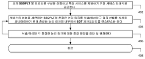
다시 도 4a를 참조하면, 단계 402에서, 초기 SSDPLT 및 초기 프로토콜 구성이 특정 서비스에 대해 구현되고, 트래픽이 그 서비스에 공급된다. 일 실시예에서, 초기 프로토콜 구성은 디폴트 프로토콜 스택에서 순서 정렬된 프로토콜의 디폴트 세트를 포함한다. 단계 404에서, 서비스의 성능을 제한하는 혼잡한 논리 링크가 SSDPLT에서 예측되거나 식별되며, 혼잡한 논리 링크 내에서 하나 이상의 SDT 체크 포인트 인스턴스가 링크 상태를 면밀히 모니터링하기 위해 인스턴스화 된다. 단계 406에서, 단계 404에서 식별되거나 예측된 혼잡한 논리 링크들 각각에 대해, 혼잡 원인이 진단되고 완화된다. 상기 방법은 단계 408에서 종료한다.Referring again to FIG. 4A, at
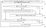
도 4b는 예를 들어, 도 2a의 네트워크 제어 시스템(238A) 또는 도 2b의 네트워크 제어 시스템(238b)과 같은 네트워크 제어 시스템을 사용하여 도 4a의 단계 402를 구현하기 위한 방법 실시예를 나타낸다. 단계 422에서, CSM은 스탠드-얼론(stand-alone) SONAC 코디네이터(예를 들어, 도 2a의 SONAC 코디네이터(214A)) 또는 네트워크 제어 시스템의 분산 내장 컴포넌트(예를 들어, 도 2b의 SONAC 조정 컴포넌트 214A 내지 214C)인, SONAC 코디네이터에게 서비스 명세를 제공한다. 하부 구조 관리부는 또한 SONAC 코디네이터에게 물리 하부 구조 정보를 제공하고, 데이터 평면(234)의 하부 구조 모니터링 컴포넌트는 SONAC 코디네이터에게 하부 구조 모니터링 업데이트를 제공한다. 이 정보를 기반으로, SONAC 코디네이터는 초기 네트워크 구성을 결정한다. 단계 424에서, SDT 컨트롤러(SONAC 조정 컴포넌트를 호스팅 할 수 있는)는 초기 네트워크 구성에 따라 데이터 평면(234)의 논리 그래프를 결정한다. 단계 426에서, SDT 컨트롤러는 논리 그래프에 따라 데이터 평면(234)의 논리 노드에서 VNF를 인스턴스화 하는, NFV 컨트롤러에게 논리 그래프를 제공한다. 단계 428에서, SDRA 컨트롤러(SONAC 조정 컴포넌트를 호스팅 할 수 있는)는 논리 그래프에 따라 데이터 평면(234)의 논리 링크에 대한 자원의 할당을 계산한다. SDRA 컨트롤러는 이 자원 할당을 TE 피더에 제공한다. 단계 430에서, TE 피더는 자원 할당에 따라, 이들 라우터들에 의해 지원되는 특정 서비스에 관련한, 데이터 평면(234)의 기초가 되는 라우터들에 대한 전달 규칙들을 설정함으로써 데이터 평면(234)의 SDN-인에이블 하부 구조를 구성한다. 단계 432에서, SDP 컨트롤러(SONAC 조정 컴포넌트를 호스트 할 수 있는)는 논리 그래프의 논리 링크를 통해 프로토콜 구성을 업데이트한다. 상기 방법은 단계 434에서 종료한다.4B illustrates a method embodiment for implementing
도 4c는, 예를 들어, 도 2a의 네트워크 제어 시스템(238A) 또는 도 2b의 네트워크 제어 시스템(238B)과 같은 네트워크 제어 시스템을 사용하여 도 4a의 단계 404 및 406을 구현하기 위한 방법 실시예를 도시한다. 단계 452에서, 하부 구조 모니터링 컴포넌트(들)는 네트워크 혼잡 문제를 식별 및/또는 예측하고 나서 진단할 수 있도록 네트워크 혼잡 이벤트 정보를 SONAC 코디네이터에게 제공한다. 네트워크 혼잡 이벤트 정보는 특정 서비스에 대한 네트워크 상태, 서비스 품질 측정치 및/또는 SDT 성능 측정을 포함 할 수 있는 서비스 특정 하부 구조 모니터링 업데이트이다. SONAC 코디네이터는 스탠드-얼론 SONAC 코디네이터(예를 들어, 도 2a의 SONAC 코디네이터(214A)) 또는 네트워크 제어 시스템의 분산된 내장 컴포넌트(예를 들어, 도 2b의 SONAC 조정 컴포넌트 214A 내지 214C) 중 하나이다.4C illustrates a method embodiment for implementing
단계 454에서, SONAC 코디네이터가 라우터 관련 문제로서 네트워크 혼잡을 진단하면, 플로우는 단계 456에서 계속된다. 그렇지 않으면, 플로우는 단계 458에서 계속된다. 단계 456에서, 혼잡 라우터와 관련된 목표 논리 링크에 의해 상호 연결된 논리 노드에서 패킷 집성 VNF를 조정하는 것, 목표 논리 링크를 통한 트래픽 플로우의 우선순위화를 높이는 것, 혼잡한 라우터가 적어도 부분적으로 바이 패스되도록 목표 논리 링크의 외부로 TE 트래픽 플로우를 구성하는 것, 및/또는 목표 논리 링크를 통해 프로토콜 구성을 조정하는 것을 포함하는, 혼잡한 라우터와 연결된 목표 논리 링크의 파라미터에 대해 조정이 트리거된다. 본 개시에서, 논리 링크, 또는 물리 링크, 또는 라우터를 "부분적으로 우회"한다는 것은, 링크 또는 라우터의 용량 제한을 존중하여 특정 서비스에 대한 플로우 할당을 강제하는 것 및/또는 링크 또는 라우터에 과부하가 걸리는 것을 피할 수 있도록 플로우 할당에 더 많은 자유도를 부여하는 것을 의미한다. 일 실시예에서, 링크 또는 라우터의 용량 제한의 강제는 네트워크에 부하가 적을 때(under-loaded) 초기부터 활성화되지 않을 수 있다. 일 실시예에서, 링크 또는 라우터의 용량 제한은 트래픽 변동을 수용하기 위한 안전 마진을 포함한다.In
다시 도 4c를 참조하면, 단계 456에서 목표 논리 링크의 파라미터 조정이 혼잡 라우터의 용량 제한을 강제하는 것을 포함할 때, 그러한 강제는, 예를 들어, SDRA 최적화의 일부로서 혼잡한 라우터에 대한 입력 큐 크기의 최소화/밸런싱을 통합하는 것과 같은 다양한 방식으로 구현 될 수 있다. 플로우는 단계 460에서 계속된다.Referring again to FIG. 4C, when the parameter adjustment of the target logical link at
단계 458에서, 링크-관련 혼잡에 대한 조정이 혼잡한 논리 링크의 파라미터에 대해 트리거된다. 이러한 링크-관련 혼잡 조정은, 예를 들어, 혼잡한 논리 링크 내의 백그라운드 트래픽을 성형하기 위해 혼잡한 논리 링크와 연결된 논리 노드에 트래픽 성형 VNF를 적용하는 것, 혼잡한 논리 링크가 적어도 부분적으로 바이패스 될 수 있도록 TE 트래픽 플로우를 혼잡한 논리 링크의 외부에 구성하는 것, 및/또는 혼잡한 논리 링크에 대한 논리 링크 파라미터의 TE 구성을 변경하는 것(예를 들어, 가장 앞쪽 트래픽에 제공된 물리 경로의 개수, 충돌하는 백그라운드 트래픽에 대한 자원 할당을 위한 SDRA/TE 모델 등)을 포함할 수 있다. 단계 460에서, SONAC 코디네이터는 하부 구조 모니터링 컴포넌트로부터 하부 구조 모니터링 업데이트를 수신한다. 혼잡 문제가 완화 되었다면, 상기 방법은 단계 464에서 종료한다. 라우터-관련 혼잡 문제가 완화되지 않았다면, 플로우는 단계 462에서 계속된다. 단계 462에서, SDT 컨트롤러는 혼잡 문제를 완화하려고 시도하기 위해서 데이터 평면(234)의 논리 그래프를 조정한다. 이후, 상기 방법은 단계 464에서 종료한다.At
도 4d는 도 4c의 단계 456을 구현하기 위한 방법 실시예를 나타낸다. 단계 466에서, 각각의 혼잡한 라우터와 연결된 목표 논리 링크(들)에 연결된 노드들의 VNF 구성에 대한 조정이 이루어진다. 이 VNF 구성 조정은, 목표 논리 링크를 통한 적응적 패킷 집성을 조정하는 것 및/또는 목표 논리 링크(들)에 대한 트래픽 우선순위화를 증가시키는 것 중 하나 이상을 포함한다. 단계 468에서, 혼잡이 완화되었다면, 상기 방법은 단계 480에서 종료한다. 그렇지 않으면, 플로우는 단계 474에서 계속되고, 여기서 SDRA/TE 플로우는 크게 부하가 걸린 임의의 혼잡한 라우터와 연결된 목표 논리 링크(들)를 적어도 부분적으로 우회하도록 조정된다. 단계 476에서, 혼잡이 완화되었다면, 상기 방법은 단계 480에서 종료한다. 그렇지 않으면, 플로우는 단계 478에서 계속되고, 여기서 프로토콜 구성은 목표 논리 링크들 내에서 조정된다. 예를 들어, 프로토콜 스택은 목표 논리 링크에 의해 상호 연결되는 데이터 평면(234)의 SDP-인에이블 노드에서 하나 이상의 프로토콜을 제거 또는 비활성화함으로써 단순화 될 수 있다. 상기 방법은 단계 480에서 종료한다.Figure 4d shows a method embodiment for implementing
도 4e는 도 4c의 단계 458를 구현하기 위한 방법 실시예를 나타낸다. 단계 486에서, 각각의 혼잡한 논리 링크에 대해, 트래픽 성형에 민감한 임의의 배경 트래픽에 트래픽 성형이 선택적으로 적용된다. 단계 488에서, 혼잡이 완화되었다면, 상기 방법은 단계 499에서 종료한다. 그렇지 않으면, 플로우는 단계 494에서 계속되고, 여기서 SDRA/TE 조정 중 하나 또는 둘 모두가 서비스 SDT 공급 당 적응의 일부로서 이루어진다. (1) SDRA / TE 구성이 혼잡한 논리 링크의 파라미터에 대해 변경된다. 및/또는 (2) SDRA/TE 플로우가 높은 트래픽 부하를 갖는 혼잡한 논리 링크(들)를 적어도 부분적으로 우회하도록 조정된다. 일 실시예에서, SDRA/TE 구성이 혼잡한 논리 링크(들)를 지원하기 위해 더 많은 물리 링크를 할당함으로써 변경된다. 단계 496에서, 혼잡이 완화되었다면, 상기 방법은 단계 499에서 종료한다. 그렇지 않다면, 플로우는 단계 498에서 계속되고, 여기서 서비스 SDT 공급 당 적응은 혼잡한 논리 링크에 연결된 SDP-인에이블 노드에서 프로토콜 구성을 조정함으로써 계속된다. 예를 들어, 큰 패킷 량과 작은 패킷 페이로드를 갖는 M2M 서비스에 대해, 헤더 크기를 줄이기 위해 프로토콜 구성을 조정하는 것은 혼잡한 논리 링크 내의 혼잡을 완화할 수 있다. 상기 방법은 단계 499에서 종료한다.Figure 4E illustrates a method embodiment for implementing
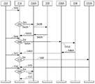
도 5a는 초기 네트워크 구성에 따라 도 2a의 SONAC-가능 네트워크(200A)를 형성하기 위한 신호 실시예를 나타낸다. CSM(202)은 SONAC 코디네이터(214)에게 서비스 명세(521)를 제공하고, 하부 구조 관리부(240)는 SONAC 코디네이터(214)에게 물리 하부 구조 정보(522)를 제공하며, 하부 구조 모니터링 컴포넌트(232)는 SONAC 코디네이터(214)가 초기 네트워크 구성(524A)을 결정할 수 있도록 SONAC 코디네이터(214)에게 네트워크 상태(523)를 제공한다.Figure 5A shows a signal embodiment for forming the SONAC-enabled
SONA 코디네이터(214)는 SDT 컨트롤러(216A)가 데이터 평면(234)의 논리 그래프 (524B)를 결정할 수 있도록 SDT 컨트롤러(216A)에게 이 초기 네트워크 구성(524A)을 제공한다. SDT 컨트롤러(216A)는 논리 그래프(524B)를 NFV 컨트롤러(220)에게 제공한다. NFV 컨트롤러(220)는, 논리 그래프(524B)에 따라 데이터 평면(234)의 논리 노드에서 VNF의 인스턴스화 이후에 인지(acknowledgement) 신호(525A)를 SDT 컨트롤러(216A)에게 제공한다. SDT 컨트롤러(216A)는 인지 신호 및 논리 그래프를 모두 포함하는 신호(525B)를 SONAC 코디네이터(214)에게 제공한다.The
그 다음, SONAC 코디네이터(214)는 SDRA 컨트롤러(218A)가 데이터 평면(234)의 링크에 대한 자원의 할당을 계산할 수 있도록 SDRA 컨트롤러(218A)에게 SDRA 트리거 신호(526A)를 제공한다. SDRA 컨트롤러(218A)는 이 자원 할당(526B)을 TE 피더에게 제공한다. 이들 라우터에 의해 지원되는 특정 서비스와 관련하여, 데이터 평면(234)의 기초가 되는 라우터에 대한 전달 규칙을 설정함으로써 SDN-인에이블 하부 구조를 구성한 이후에, TE 피더(224)는 인지 신호(527A)를 SDRA 컨트롤러(218A)에게 송신한다. SDRA 컨트롤러(218A)는 SONAC 코디네이터(214)에게 인지 신호(527B)를 송신한다. SONAC 코디네이터(214)는, SDA 컨트롤러(222A)가 데이터 평면(234)의 논리 링크를 통해 프로토콜을 구성할 수 있도록 SDP 트리거 신호(528)를 송신한다. 이들 프로토콜을 구성한 후, SDP 컨트롤러(222A)는 인지 신호(529)를 SONAC 코디네이터(214)에게 송신하고, SONAC 코디네이터(214)는 하부 구조 모니터링 컴포넌트(232)로부터 제2 하부 구조 모니터링 업데이트(530)를 수신한다.The
도 5b는 라우터-관련 혼잡 동안에 도 2a의 SONAC-가능 네트워크(200A)의 구성을 업데이트 하기 위한 신호 실시예를 나타낸다. 하부 구조 모니터링 컴포넌트(232)는 SONAC 코디네이터(214)가 네트워크 혼잡 문제를 분석 및 진단할 수 있도록 네트워크 혼잡 이벤트 정보(541)를 SONAC 코디네이터(214)에게 제공한다. 네트워크 혼잡 이벤트 정보(541)는 네트워크 상태, 서비스 품질 측정 및/또는 SDT 성능 측정치를 포함할 수 있는 하부 구조 모니터링 업데이트이다.FIG. 5B shows a signal embodiment for updating the configuration of the SONAC-enabled
단계 454(도 4c에 도시 됨)에서 SONAC 코디네이터(214)가 네트워크 혼잡을 라우터 관련 문제라고 진단하면, SONAC 코디네이터(214)는 네트워크 혼잡이 라우터 관련 문제인지를 나타내는 신호(542A)를 SDT 컨트롤러(216A)에 전송한다. SDT 컨트롤러(216A)는, NFV 컨트롤러(220)가 각 혼잡한 라우터와 연결된 목표 논리 링크(들)에 연결된 노드들의 VNF 구성들에 대한 내리도록 지시하는 신호 (542B)를 송신한다. 이 VNF 구성 조정은, 목표 논리 링크에 대한 적응적 패킷 집성을 조정하는 것, 및/또는 목표 논리 링크(들)에 대한 트래픽 우선순위화를 증가시키는 것 중 하나 이상을 포함한다. 일단 NFV 컨트롤러(220)가 VNF 구성을 조정하면, 그것은 인지 신호(543)를 SONAC 코디네이터(214)에게 전송한다.If
그 다음, SONAC 코디네이터(214)는 혼잡 문제가 완화되었는지 여부를 확인하기 위해서 하부 구조 모니터링 컴포넌트(232)로부터 하부 구조 모니터링 업데이트(544)를 수신한다. 혼잡 문제가 단계 468(도 4d에 도시됨)에서 완화되지 않으면, SONAC 코디네이터(214)는 SDA 컨트롤러(218A)에게, 예를 들어, 혼잡한 라우터가 적어도 부분적으로 바이패스 될 수 있도록 트래픽 플로우를 목표 논리 링크의 외부로 구성하는 것을 포함하는, 라우터-관련 혼잡 문제를 완화 시키기 위한 트래픽 흐름을 조정하는 자원 할당을 결정하도록 지시하는 신호(545A)를 송신한다. SDAR은 자원 할당(545B)을 TE 피더(224)에게 제공한다. TE 피더 (224)는, 자원 할당에 따라, 이들 라우터들에 의해 지원되는 특정 서비스에 대해 데이터 평면(234)의 기초가 되는 라우터들에 대한 전달 규칙들을 갱신하고, TE 피더(224)는 SDRA 컨트롤러(218A)에게 인지 신호(546A)를 제공한다. SDRA 컨트롤러(218A)는 SONAC 코디네이터(214)에게 인지 신호(546B)를 제공하고, SONAC 코디네이터(214)는 하부 구조 모니터링 컴포넌트(232)로부터 또 다른 하부 구조 모니터링 업데이트(547)를 수신한다.The
혼잡 문제가 단계 476(도 4d에 도시됨)에서 완화되지 않으면, SONAC 코디네이터(214)는 라우터-관련 혼잡 문제를 완화 시키려고 시도하기 위해 목표 논리 링크를 통한 프로토콜 구성을 조정하도록 지시하는 신호(548)를 SDP 컨트롤러(222A)에게 송신한다. 일단 SDP 컨트롤러(222A)가 이 프로토콜 구성을 조정하면, SONAC 코디네이터(214)에게 인지 신호(549)를 전송하고, SONAC 코디네이터(214)는 하부 구조 모니터링 컴포넌트(232)로부터 또 다른 하부 구조 모니터링 업데이트(550)를 수신한다. 혼잡 문제가 단계 460(도 4c에 도시됨)에서 완화되지 않으면, SONAC 코디네이터(214)는, 혼잡 문제를 완화 시키려고 시도하기 위해 데이터 평면(234)의 논리 그래프를 조정하도록 SDT 컨트롤러(216A)를 트리거하기 위한 신호(551)를 SDT 컨트롤러(216A)에게 송신한다. SDT 컨트롤러(216A)는 데이터 평면(234)의 업데이트 된 논리 그래프를 결정하고, 인지 신호(552)를 SONAC 코디네이터(214)에 제공한다.If the congestion problem is not mitigated at step 476 (shown in FIG. 4D), the
도 5C는 링크-관련 혼잡 동안 도 2A의 SONAC-가능 네트워크(200A)의 구성을 업데이트 하기 위한 신호 실시예를 나타낸다. 하부 구조 모니터링 컴포넌트(232)는 SONAC 코디네이터(214)가 네트워크 혼잡 문제를 분석 및 진단할 수 있도록 네트워크 혼잡 이벤트 정보(541)를 SONAC 코디네이터(214)에게 제공한다. SONAC 코디네이터(214)가 단계 454(도 4c에 도시됨)에서 네트워크 관련 혼잡이 라우터-관련이 아니라고 진단하면, SONAC 코디네이터(214)는 네트워크-혼잡은 링크-관련 문제인 것을 가리키는 신호(562A)를 SDT 컨트롤러(216A)에 송신한다. SDT 컨트롤러(216A)는 혼잡한 논리 링크들을 연결하는 논리 노드에 트래픽 성형 VNF를 적용하도록 NFV 컨트롤러(220)에게 지시하는 신호(562B)를 송신하며, 이 트래픽 성형 VNF는 혼잡한 논리 링크들에 대해 백그라운드 트래픽을 성형하려고 시도한다. 일단 NFV 컨트롤러(220)가 트래픽 성형 VNF를 적용하면, 그것은 인지 신호(563)를 SONAC 코디네이터(214)에게 송신한다.Fig. 5C shows a signal embodiment for updating the configuration of the SONAC-enabled
그 다음, SONAC 코디네이터(214)는 혼잡 문제가 완화되었는지 여부를 체크하기 위해서 하부 구조 모니터링 컴포넌트(232)로부터 하부 구조 모니터링 업데이트(564)를 수신한다. 혼잡 문제가 단계 488(도 4e에 도시 됨)에서 완화되지 않으면, SONAC 코디네이터(214)는 링크-관련 혼잡 문제를 완화 시키려고 시도하기 위해 TE 트래픽 플로우를 조정하도록 지시하는 신호(565A)를 SDRA 컨트롤러(218A)에게 송신한다. SDRA 컨트롤러(218A)는, 예를 들어, 혼잡한 논리 링크에 대한 논리 링크 파라미터의 TE 구성을 변경하는 것 및/또는 혼잡한 논리 링크가 부분적으로 바이패스 되도록 TE 트래픽 플로우를 혼잡한 논리 링크의 외부로 구성하는 것을 포함하는, 링크-관련 혼잡 문제를 완화하기 위해 시도하기 위해 TE 트래픽 플로우 조정하는 자원 할당(565B)을 결정한다. SDAR 컨트롤러(218A)는 TE 피더(224)에게 자원 할당(565B)을 제공한다. TE 피더(224)는 자원 할당에 따라 이들 라우터들에 의해 지원되는 특정 서비스에 대해 데이터 평면(234)의 기초가 되는 라우터들에 대한 전달 규칙들을 업데이트 하고, 이후 TE 피더(224)는 SDRA 컨트롤러(218A)에게 인지 신호(566A)를 제공한다. SDRA 컨트롤러(218A)는 SONAC 코디네이터(214)에게 인지 신호(566B)를 제공하고, SONAC 코디네이터(214)는 하부 구조 모니터링 컴포넌트(232)로부터 다른 하부 구조 모니터링 업데이트(567)를 수신한다.The
혼잡 문제가 단계 496(도 4e에 도시됨)에서 완화되지 않으면, SONAC 코디네이터(214)는 혼잡한 논리 링크를 통해 프로토콜 구성을 조정하여 혼잡 문제를 완화하려고 시도하도록 지시하는 신호(568)를 SDP 컨트롤러(222A)에게 송신한다. 일단 SDP 컨트롤러(222A)가 이 프로토콜 구성을 조정하면, 그것은 SONAC 코디네이터(214)에게 인지 신호(569)를 전송하고, SONAC 코디네이터(214)는 하부 구조 모니터링 컴포넌트(232)로부터 또 다른 하부 구조 모니터링 업데이트(570)를 수신한다. 만약, 혼잡 문제가 단계 460에서 완화되지 않으면(도 4c에 도시됨), SONAC 코디네이터(214)는 혼잡 문제를 완화하도록 시도하기 위해 데이터 평면(234)의 논리 그래프를 조정하기 위해 SDT 컨트롤러(216A)를 트리거하도록 SDT 컨트롤러(216A)에게 신호(571)를 송신한다. SDT 컨트롤러(216A)는 데이터 평면(234)의 업데이트 된 논리 그래프를 결정한 후, 인지 신호(572)를 SONAC 코디네이터(214)에게 제공한다.If the congestion problem is not mitigated in step 496 (shown in FIG. 4E), the
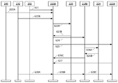
도 6a는 초기 네트워크 구성에 따라 도 2b의 SONAC-가능 네트워크(200B)를 형성하기 위한 신호 실시예를 나타낸다. CSM(202)은 SDT 컨트롤러(216B)에게 서비스 명세(621)를 제공하고, 하부 구조 관리부(240)는 SDT 컨트롤러(216B)에게 물리 하부 구조 정보(622A)를 제공하고, 하부 구조 모니터링 컴포넌트(232)는 초기 네트워크 구성 및 데이터 평면(234)의 노닐 그래프(623A)를 결정할 수 있도록 SDT 컨트롤러(216B)에게 하부 구조 모니터링 업데이트(622B)를 제공한다. SDT 컨트롤러(216A)는 논리 그래프(623A)를 NFV 컨트롤러(220)에게 제공한다. 논리 그래프(623A)에 따라 데이터 평면(234)의 논리 노드에서 VNF를 인스턴스화 한 후, NFV 컨트롤러(220)는 인지 신호(623B)를 SDT 컨트롤러(216B)에게 제공한다.FIG. 6A shows a signal embodiment for forming the SONAC-enabled
SDT 컨트롤러(216B)는, 논리 그래프의 논리 링크들에 대한 자원 할당을 계산하도록 SDRA 컨트롤러(218B)를 트리거하는, 논리 그래프를 포함하는, 신호(624)를 SDRA 컨트롤러(218B)에게 제공한다. SDRA 컨트롤러(218B)는 또한 데이터 평면(234)의 논리 링크를 통해 SDP를 구성하도록 SDP 컨트롤러(222B)를 트리거하는, 논리 그래프를 포함하는 신호(625)를 송신한다.
자원 할당(626A)을 계산한 후, SDAR 컨트롤러(218B)는 이러한 자원 할당을 TE 피더(224)에게 제공한다. 이러한 라우터들에 의해 지원되는 특정 서비스와 관련된, 데이터 평면(234)의 기초가 되는 라우터들에 대한 전달 규칙들을 설정함으로써 SDN-인에이블 하부 구조를 구성한 후, TE 피더(224)는 인지 신호(626B)를 SDRA 컨트롤러(218B)에게 송신한다. SDRA 컨트롤러(218B)는 인지 신호(626C)를 SDT 컨트롤러(216B)에게 송신한다.After computing the
데이터 평면(234)의 프로토콜 구성을 업데이트 한 후, SDP 컨트롤러(222B)는 인지 신호(627)를 SDT 컨트롤러(216B)에게 송신하고, SDT 컨트롤러(216B)는 하부 구조 모니터링 컴포넌트(232)로부터 신호(628A) 내의 제2 하부 구조 모니터링 업데이트를 수신한다. 하부 구조 모니터링 업데이트는 신호(628B)에서 SDT 컨트롤러(216B)에 의해 SDRA 컨트롤러(218B)에게 제공되고, 또한 신호(628C)에서 SDRA 컨트롤러(218B)에 의해 SDP 컨트롤러(222B)에게 제공된다.After updating the protocol configuration of the
도 6b는 라우터-관련 혼잡 동안 도 2b의 SONAC-가능 네트워크(200B)의 구성을 업데이트 하기 위한 신호 실시예를 나타낸다. 하부 구조 모니터링 컴포넌트(232)는 네트워크 혼잡 문제를 분석 및 진단할 수 있도록 SDT 컨트롤러(216B)에게 네트워크 혼잡 이벤트 정보(641)를 제공한다. 네트워크 혼잡 이벤트 정보(641)는 네트워크 상태, 서비스 품질 측정치, 및/또는 SDT 성능 측정치을 포함할 수 있는 하부 구조 모니터링 업데이트이다.Fig. 6B shows a signal embodiment for updating the configuration of the SONAC-enabled
SDT 컨트롤러(216B)가 단계 454(도 4c에 도시됨)에서 네트워크 혼잡을 라우터-관련 문제라고 진단하면, NFV 컨트롤러(220)에게 각 혼잡한 라우터와 연결된 목표 논리 링크에 연결된 노드들의 VNF 구성들에 대한 조정을 지시하는 신호(642)를 송신한다. 이 VNF 구성 조정은, 목표 논리 링크에 대한 적응적 패킷 집성을 조정하는 것, 및/또는 목표 논리 링크(들)에 대한 트래픽 우선 순위를 증가시키는 것 중 하나 이상을 포함한다. NFV 컨트롤러(220)가 VNF 구성을 조정하면, NFV 컨트롤러(220)는 인지 신호(643A)를 SDT 컨트롤러(216B)에게 송신한다.If the
그 다음, SDT 컨트롤러(216B)는 혼잡 문제가 완화되었는지 여부를 확인하기 위해서 하부 구조 모니터링 컴포넌트(232)로부터 하부 구조 모니터링 업데이트(644A)를 수신한다. SDT 컨트롤러(216B)는 신호(644B)에서 SDRA 컨트롤러(218B)에게 이러한 하부 구조 모니터링 업데이트를 제공하며, SDB 컨트롤러(222B)에게 신호(644C)의 하부 구조 모니터링 업데이트를 또한 제공한다. 혼잡 문제가 단계 468(도 4d에 도시됨)에서 완화되지 않으면, SDRA 컨트롤러(218B)는, 예를 들어, 혼잡한 라우터가 적어도 부분적으로 바이패스 될 수 있도록 트래픽 플로우를 목표 논리 링크의 외부로 구성하는 것을 포함하는, 라우터-관련 혼잡 문제를 완화 시키기 위해 트래픽 흐름을 조정하는 자원 할당(645)을 결정한다. SDRA는 TE 피더(224)에게 자원 할당(645)을 제공한다. TE 피더(224)는 자원 할당에 따라 데이터 평면(234)의 영향받은 라우터에서 전달 규칙을 업데이트 하고, TE 피더(224)는 인지 신호(646)를 SDRA 컨트롤러(218B)에게 제공한다. SDRA 컨트롤러(218B)는 신호 647A 및 647B에서, 방금 수행 된 동작의 인지 및 설명을 포함하는 메시지를 제공한다. SDRA 컨트롤러는 SDP 컨트롤러(222B)에게 신호 (647A)를 송신하고 SDT 컨트롤러(216B)에게 신호(647B)를 송신한다.The
SDT 컨트롤러(216B)는 하부 구조 모니터링 컴포넌트(232)로부터 또 다른 하부 구조 모니터링 업데이트(648A)를 수신한다. SDT 컨트롤러(216B)는 신호(648B) 내의 하부 구조 모니터링 업데이트를 SDRA 컨트롤러(218B)에게 제공하고, 또한 신호(648C) 내의 하부 구조 모니터링 업데이트를 SDP 컨트롤러(222B)에게 제공한다. 혼잡 문제가 단계 476(도 4d에 도시됨)에서 완화되지 않으면, SDP 컨트롤러(222B)는 라우터 관련 혼잡 문제를 완화 시키려고 시도하기 위해 목표 논리 링크를 통해 프로토콜 구성을 조정한다. SDP 컨트롤러(222B)가 이러한 프로토콜 구성을 조정하면, 그것은 방금 수행된 동작의 인지 및 설명을 포함하는, 메시지(650A)를 SDRA 컨트롤러(218B)에게 송신하고, SDRA 컨트롤러(218B)는 신호(650B)로서 이 메시지를 SDT 컨트롤러(216B)에 전달한다.The
SDT 컨트롤러(216B)는 하부 구조 모니터링 컴포넌트(232)로부터 또 다른 하부 구조 모니터링 업데이트(651A)를 수신한다. SDT 컨트롤러(216B)는 신호(651B)에서 하부 구조 모니터링 업데이트를 SDRA 컨트롤러(218B)에게 제공하고, 또한, 신호(651C)에서 하부 구조 모니터링 업데이트를 SDP 컨트롤러(222B)에게 제공한다. 혼잡 문제가 단계 460(도 4c에 도시됨)에서 완화되지 않으면, SDT 컨트롤러(216B)는 혼잡 문제를 완화하려고 시도하기 위해 데이터 평면(234)의 논리 그래프를 조정한다. 그 다음, SDT 컨트롤러(216B)는 SDRA 컨트롤러(218B)에게, 방금 수행된 동작의 인지 및 설명을 포함하는 메시지(653A)를 제공하고, 이 메시지를 신호(653B)로서 SDP 컨트롤러(222B)에 전달한다.The
도 6c는 링크-관련 혼잡 동안 도 2b의 SONAC-가능 네트워크(200B)의 구성을 업데이트 하기 위한 신호 실시예를 나타낸다. 하부 구조 모니터링 컴포넌트(232)는 네트워크 혼잡 문제를 분석 및 진단할 수 있도록 SDT 컨트롤러(216B)에게 네트워크 혼잡 이벤트 정보(641)를 제공한다. SDT 컨트롤러(216B)가 단계 454(도 4c에 도시됨)에서 네트워크-관련 혼잡이 링크-관련 문제라고 진단하면, NFV 컨트롤러(220)에게 혼잡한 논리 링크 내의 백그라운드 트래픽에 대해 트래픽 성형을 적용하도록 지시하는 신호(662)를 송신한다. 일단 NFV 컨트롤러(220)가 하나 이상의 트래픽 성형 VNF를 적용하면, 그것은 인지 신호(663A)를 SDT 컨트롤러(216B)에게 송신한다.Fig. 6C shows a signal embodiment for updating the configuration of the SONAC-enabled
그 다음, SDT 컨트롤러(216B)는 혼잡 문제가 완화되었는지 여부를 확인하기 위해서 하부 구조 모니터링 컴포넌트(232)로부터 하부 구조 모니터링 업데이트(664A)를 수신한다. SDT 컨트롤러(216B)는 신호(664B)에서 SDRA 컨트롤러(218B)에게 이러한 하부 구조 모니터링 업데이트를 제공하며, 또한 SDP 컨트롤러(222B)에게 신호(664C)에서 하부 구조 모니터링 업데이트를 제공한다. 혼잡 문제가 단계 488(도 4E에 도시 된)에서 완화되지 않으면, SDA 컨트롤러(218B)는, 예를 들어 혼잡한 논리 링크에 대한 논리 링크 파라미터의 TE 구성을 변경하는 것 및/또는 혼잡한 논리 링크가 적어도 부분적으로 바이패스 될 수 있도록 혼잡한 논리 링크의 외부로 TE 트래픽 플로우를 구성하는 것을 포함하는, 링크 관련 혼잡 문제를 완화 시키기 위한 시도를 위해 트래픽 플로우를 조정하는 자원 할당(665)을 결정한다. SDRA는 TE 피더(224)에게 자원 할당(665)를 제공한다. TE 피더(224)는 자원 할당에 따라 데이터 평면(234)의 영향을 받은 라우터에서 전달 규칙을 업데이트 한 다음, TE 피더(224)는 인지 신호(666)를 SDRA 컨트롤러(218B)에게 제공한다. SDRA 컨트롤러(218B)는 신호 667A 및 667B에서, 방금 수행된 동작의 인지 및 설명을 포함하는 메시지를 제공한다. SDRA 컨트롤러는 신호(667A)를 SDP 컨트롤러(222B)에게 송신하고, 신호(667B)를 SDT 컨트롤러(216B)에게 송신한다.The
SDT 컨트롤러(216B)는 하부 구조 모니터링 컴포넌트(232)로부터 또 다른 하부 구조 모니터링 업데이트(668A)를 수신한다. SDT 컨트롤러(216B)는 신호(668B)의 하부 구조 모니터링 업데이트를 SDRA 컨트롤러(218B)에게 제공하며, 또한, 신호(668C)의 하부 구조 모니터링 업데이트를 SDP 컨트롤러(222B)에게 제공한다. 혼잡 문제가 단계 496(도 4e에 도시됨)에서 완화되지 않으면, SDP 컨트롤러(222B)는 링크-관련 혼잡 문제를 완화하려고 시도하기 위해 혼잡한 논리 링크를 통해 프로토콜 구성을 조정한다. SDP 컨트롤러(222B)가 이러한 프로토콜 구성을 조정하면, 그것은 방금 실행된 동작의 인지 및 설명을 포함하는 메시지(670A)를 SDRA 컨트롤러(218B)에게 송신하고, 이 메시지를 신호(670B)로서 SDT 컨트롤러(216B)에게 전달한다.The
SDT 컨트롤러(216B)는 하부 구조 모니터링 컴포넌트(232)로부터 다른 하부 구조 모니터링 업데이트(671A)를 수신한다. SDT 컨트롤러(216B)는 신호(671B)의 하부 구조 모니터링 업데이트를 SDRA 컨트롤러(218B)에게 제공하고, 또한 신호(671C)의 하부 구조 모니터링 업데이트를 SDP 컨트롤러(222B)에게 제공한다. 혼잡 문제가 단계 460(도 4c에 도시됨)에서 완화되지 않으면, SDT 컨트롤러(216B)는 혼잡 문제를 완화하려고 시도하기 위해 데이터 평면(234)의 논리 그래프를 조정한다. 그 후, SDT 컨트롤러(216B)는 SDRA 컨트롤러(218B)에게, 방금 수행된 동작의 인지 및 설명을 포함하는 메시지(673A)를 제공하고, SDRA 컨트롤러(218B)는 이 메시지를 신호(673B)로서 SDP 컨트롤러(222B)에게 전달한다.The
도 7a는 호스트 장치에 설치될 수 있는, 여기서 기술된 방법을 수행하기 위한 처리 시스템(700)의 실시예의 블록도를 도시한다. 보여진 대로, 처리 시스템(700)은 도 7에 도시된 바와 같이 배열될 수 있는(또는 배열될 수 없는) 프로세서(704), 메모리(706), 및 인터페이스(710-714)를 포함한다. 프로세서(704)는 계산 및/또는 다른 프로세싱 관련 태스크를 수행하도록 적응된 임의의 컴포넌트 또는 컴포넌트의 모음일 수 있고, 메모리(706)는 프로세서(704)에 의한 실행을 위한 프로그래밍 및/또는 명령을 저장하도록 적응된 임의의 컴포넌트 또는 컴포넌트의 모음일 수 있다. 일 실시예에서, 메모리(706)는 비-일시적인 컴퓨터 판독 가능 매체를 포함한다. 인터페이스(710, 712, 714)는 처리 시스템(700)이 다른 장치/컴포넌트 및/또는 사용자와 통신할 수 있게 하는 임의의 구성 요소 또는 구성 요소의 모음일 수 있다. 예를 들어, 하나 이상의 인터페이스(710, 712, 714)는 데이터, 또는 제어, 또는 관리 메시지를 프로세서(704)로부터 호스트 장치 및/또는 원격 장치에 설치된 애플리케이션으로 전달하도록 적응될 수 있다. 다른 예로서, 하나 이상의 인터페이스(710, 712, 714) 중 사용자 또는 사용자 디바이스(예를 들어, 퍼스널 컴퓨터(Personal Computer, PC) 등)가 처리 시스템(700)과 상호 작용/통신할 수 있도록 적응될 수 있다. 프로세싱 시스템(700)은 도 7에 도시되지 않은 장기 저장소(예를 들어, 비-휘발성 메모리 등)와 같은 추가적인 컴포넌트를 포함할 수 있다.7A shows a block diagram of an embodiment of a
일부 실시예에서, 처리 시스템(700)은 원격통신 네트워크에 액세스하는 네트워크 장치에 포함되거나, 그렇지 않으면 원격통신 네트워크의 일부를 구성하는 네트워크 장치에 포함된다. 일 예시에서, 처리 시스템(700)은 기지국, 또는 중계국, 또는 스케줄러, 또는 컨트롤러, 또는 게이트웨이, 또는 라우터, 애플리케이션 서버, 또는 원격통신 네트워크의 임의의 다른 장치와 같은 무선 또는 유선 통신 네트워크 내의 네트워크 측 장치이다. 다른 실시예에서, 처리 시스템(700)은 이동국, UE, PC, 태블릿, 웨어러블 통신 장치(예를 들어, 스마트 워치 등), 또는 원격통신 네트워크에 액세스 하도록 적응된 임의의 다른 장치와 같은, 무선 또는 유선 원격통신 네트워크에 액세스하는 사용자 측 장치이다. In some embodiments, the
일부 실시예에서, 하나 이상의 인터페이스(710, 712, 714)는 처리 시스템 (700)을 원격통신 네트워크를 통해 시그널링을 송신 및 수신하도록 적응된 트랜시버에 연결한다. 도 7B는 원격통신 네트워크를 통해 시그널링을 송신 및 수신하도록 적응된 트랜시버(750)의 블록도를 도시한다. 트랜시버(750)는 호스트 장치에 설치될 수 있다. 보여진 대로, 트랜시버(750)는 네트워크 측 인터페이스(752), 커플러(coupler)(754), 전송기(756), 수신기(758), 신호 프로세서(760), 및 장치 측 인터페이스(762)를 포함한다. 네트워크 측 인터페이스(752)는 무선 또는 유선 원격통신 네트워크를 통해 시그널링을 전송하거나 수신하도록 적응된 임의의 컴포넌트 또는 컴포넌트의 모음을 포함할 수 있다. 커플러(754)는 네트워크 측 인터페이스(752)를 통한 양방향 통신을 용이하게 하도록 적응된 임의의 컴포넌트 또는 컴포넌트의 모음을 포함할 수 있다. 전송기(756)는 네트워크 측 인터페이스(752)를 통한 전송에 적합한 변조된 반송파 신호로 기저대역 신호를 변환하도록 적응된 임의의 컴포넌트 또는 컴포넌트의 모음(예를 들어, 업 컨버터, 전력 증폭기 등)을 포함할 수 있다. 수신기(758)는 네트워크 측 인터페이스(752)를 통해 수신된 반송파 신호를 기저 대역 신호로 변환하도록 적응된 임의의 컴포넌트 또는 컴포넌트의 모음(예를 들어, 다운 컨버터, 저잡음 증폭기 등)을 포함할 수 있다. 신호 프로세서(760)는 기저 대역 신호를 장치 측 인터페이스(들)(762)를 통한 통신에 적합한 데이터 신호로 또는 그 역으로 변환하도록 적응된 임의의 컴포넌트 또는 컴포넌트의 모음을 포함할 수 있다. 장치 측 인터페이스(들)(762)는 신호 프로세서(760)와 호스트 장치 내의 컴포넌트(예를 들어, 처리 시스템(700), 근거리 통신망(Local Area Network, LAN) 포트 등) 사이에서 데이터 신호를 통신하도록 적응된 임의의 컴포넌트 또는 컴포넌트의 모음을 포함할 수 있다. In some embodiments, one or more of the
트랜시버(750)는 임의의 유형의 통신 매체를 통해 시그널링을 송신 및 수신할 수 있다. 일부 실시예에서, 트랜시버(750)는 무선 매체를 통해 시그널링을 송신 및 수신한다. 예를 들어, 트랜시버(750)는 셀룰러 프로토콜(예를 들어, LTE(Long-Term Evolution) 등), 또는 WLAN(Wireless Local Area Network), 또는 임의의 다른 유형의 무선 프로토콜(예를 들어, 블루투스, 근거리 통신(Near Field Communication, NFC) 등)과 같은, 무선 원격통신 프로토콜에 따라서 통신하도록 적응된 무선 트랜시버일 수 있다. 이러한 실시예에서, 네트워크 측 인터페이스(752)는 하나 이상의 안테나/방사 소자를 포함한다. 예를 들어, 네트워크 측 인터페이스 (752)는 단일 안테나, 또는 복수의 분리 안테나, 또는 예를 들어, SIMO(Single Input Multiple Output), MISO(Multiple Input Single Output), MIMO(Multiple Input Multiple Output) 등의 다층 통신을 위해 구성된 다중 안테나 어레이를 포함 할 수 있다. 다른 실시예에서, 트랜시버(750)는 유선 매체, 예를 들어, 꼬인 쌍 케이블, 동축 케이블, 광섬유 등을 통해 시그널링을 송신 및 수신한다. 특정 처리 시스템들 및/또는 트랜시버들은 표시된 모든 컴포넌트 또는 컴포넌트의 서브세트만을 활용할 수 있고, 통합 레벨은 장치마다 다를 수 있다.
본 발명의 예시적인 실시예는 향상된 네트워크 성능 및 QoS/QoE 보증을 제공한다는 이점을 갖는다. 일부 실시예에서, 네트워크 제어 시스템은 개선된 성능, 또는 정기적으로 수행되는 네트워크 업데이트 프로세스의 오버헤드 감소, 또는 정기적으로 수행되는 네트워크 업데이트 간의 연장된 지속 기간을 허용하기 위해 데이터 평면 논리 토폴로지의 네트워크-중심 실시간 적응을 조정할 수 있다.The exemplary embodiment of the present invention has the advantage of providing enhanced network performance and QoS / QoE assurance. In some embodiments, the network control system may provide a network-centric approach to the data plane logical topology to allow for improved performance, or reduced overhead of periodically performed network update processes, or extended duration between periodically performed network updates. Real-time adaptation can be adjusted.
아래에서는 본 발명의 추가적인 예시적 실시예가 또한 제공된다. 본 발명의 제1 실시예에 따르면, 네트워크 적응 방법이 제공된다. 상기 방법은, 가상 네트워크의 적응 코디네이터가, 가상 네트워크 내에 위치된 성능 체크포인트에서 생성된 성능 측정치를 수신하는 단계를 포함한다. 상기 방법은 또한 적응 코디네이터가, 가상 네트워크의 서비스 특정 구성의 제1 업데이트를 생성하는 단계를 포함한다. 제1 업데이트는 성능 체크포인트 구성의 변경, 또는 가상 네트워크 기능(Virtual Network Function, VNF) 구성의 변경, 또는 프로토콜 구성의 변경, 또는 자원 할당 입력의 변경, 또는 논리 그래프의 변경 중 적어도 하나를 포함한다. 서비스 특정 구성은 서비스 특정 데이터 평면 논리 토폴로지에 따라 가상 네트워크의 복수의 논리 노드 및 복수의 논리 링크의 구성을 포함한다.Further exemplary embodiments of the present invention are provided below. According to a first embodiment of the present invention, a network adaptation method is provided. The method includes the step of the adaptation coordinator of the virtual network receiving a performance measure generated at a performance checkpoint located in the virtual network. The method also includes an adaptation coordinator generating a first update of a service specific configuration of the virtual network. The first update includes at least one of a change in a performance checkpoint configuration or a change in a Virtual Network Function (VNF) configuration, a change in a protocol configuration, a change in a resource allocation input, or a change in a logical graph . The service specific configuration includes a plurality of logical nodes of the virtual network and a plurality of logical links in accordance with the service specific data plane logical topology.
또한, 앞서 설명한 제1 실시 예는 다음의 추가 특징 중 하나 이상을 포함하도록 구현될 수 있다. 상기 방법은 또한 가상 네트워크의 제1 컨트롤러에게 제1 업데이트를 제공하는 단계를 포함하도록 구현될 수 있다. 상기 방법은 또한 제1 컨트롤러가 SDT(Software Defined Topology) 컨트롤러, 또는 SDP(Software Defined Protocol) 컨트롤러, 또는 SDRA(Software Defined Resource Allocation) 컨트롤러 중 적어도 하나를 포함하도록 구현될 수 있다.In addition, the first embodiment described above can be implemented to include one or more of the following additional features. The method may also be implemented to include providing a first update to a first controller of the virtual network. The method may also be implemented such that the first controller comprises at least one of a Software Defined Topology (SDT) controller, a Software Defined Protocol (SDP) controller, or an SDRA (Software Defined Resource Allocation) controller.
상기 방법은 또한 성능 체크 포인트 구성의 변경이, 성능 체크 포인트 위치의 변경, 또는 성능 체크 포인트의 삭제, 또는 성능 체크 포인트의 인스턴스화 중 적어도 하나를 포함하도록 구현될 수 있다. 상기 방법은 또한 VNF 구성의 변경이, VNF 위치의 변경, 또는 VNF 인스턴스의 비활성화, 또는 VNF 인스턴스의 삭제, 또는 VNF 인스턴스의 활성화, 또는 인스턴스 생성 중 적어도 하나를 포함하도록 구현될 수 있다. 상기 방법은 또한 그러한 프로토콜 구성의 변경이, 프로토콜 정의의 변경, 또는 프로토콜 인스턴스의 비활성화, 또는 프로토콜 인스턴스의 삭제, 또는 프로토콜 인스턴스의 활성화, 또는 프로토콜 인스턴스, 또는 프로토콜 실행의 재정렬 중 적어도 하나를 포함하도록 구현될 수 있다.The method may also be implemented such that the change in the performance checkpoint configuration includes at least one of changing the performance checkpoint location, deleting the performance checkpoint, or instantiating the performance checkpoint. The method may also be implemented such that a change in the VNF configuration includes at least one of changing the VNF location, deactivating the VNF instance, deleting the VNF instance, activating the VNF instance, or creating an instance. The method may also be implemented such that changes to such a protocol configuration include at least one of altering a protocol definition, deactivating a protocol instance, deleting a protocol instance, activating a protocol instance, or reordering a protocol instance or protocol execution .
상기 방법은 또한 논리 그래프의 변경이, 논리 노드 위치의 변경, 또는 논리 노드의 삭제, 또는 논리 노드의 추가, 또는 논리 노드의 삭제, 또는 논리 노드의 추가, 또는 논리 노드의 삭제, 또는 논리 링크 위치의 수정변경, 또는 논리 링크의 삭제, 또는 논리 링크의 추가 중 적어도 하나를 포함하도록 구현될 수 있다. 상기 방법은 또한 가상 네트워크의 데이터 평면이 복수의 논리 노드 및 복수의 논리 링크를 포함하도록 구현될 수 있다. 상기 방법은 또한 성능 측정이 지연, 또는 지연 지터, 또는 스루풋, 또는 라우터 큐 상태 중 적어도 하나를 포함하도록 구현될 수 있다. 상기 방법은 또한 서비스 특정 구성과 연관된 네트워크 서비스가 장치대장치 서비스를 포함하도록 구현될 수 있다. 상기 방법은 또한 제1 컨트롤러가 적응 코디네이터의 일부를 포함하도록 구현될 수 있다.The method may also include altering a logical graph, changing a logical node location, or deleting a logical node, or adding a logical node, or deleting a logical node, or adding a logical node, or deleting a logical node, Modification of a logical link, deletion of a logical link, or addition of a logical link. The method may also be implemented such that the data plane of the virtual network comprises a plurality of logical nodes and a plurality of logical links. The method may also be implemented such that the performance measurement includes at least one of delay, delay jitter, or throughput, or router queue status. The method may also be implemented such that the network service associated with the service specific configuration includes device-to-device service. The method may also be implemented such that the first controller includes a portion of the adaptation coordinator.
상기 방법은 또한 자원 할당 입력의 변경이, 플로우 할당이 데이터 평면의 복수의 논리 링크 중 제1 논리 링크의 용량 제한, 또는 라우터의 용량 제한, 또는 물리 링크의 용량 제한 중 하나를 포함하는 제1 용량 제한을 초과하는 것을 방지하기 위한 변경, 또는 상기 플로우 할당이 제1 논리 링크에 과부하가 걸리는 것을 피하도록 허용하기 위한 변경, 또는 플로우 할당이 라우터에 과부하가 걸리는 것을 피하도록 허용하기 위한 변경, 또는 플로우 할당이 물리 링크에 과부하가 걸리는 것을 피하도록 허용하기 위한 변경, 또는 제1 논리 링크에 할당될 물리 경로의 수량에 대한 변경 중 적어도 하나를 포함하도록 구현될 수 있다. 상기 방법은 또한 VNF 구성의 변경이, 제1 논리 링크의 적응적 패킷 집성의 변경, 또는 제1 논리 링크의 트래픽 성형 구성의 변경, 또는 제1 논리 링크의 트래픽 우선순위화의 변경 중 적어도 하나를 포함하도록 구현될 수 있다. 상기 방법은 또한, 성능 측정치가 트래픽 혼잡이 제1 논리 링크와 연결된 라우터의 입력 큐에 존재함을 가리키도록 구현될 수 있다.The method also includes changing a resource allocation input to a first capacity that includes one of a capacity limitation of a first logical link of a plurality of logical links of a data plane or a capacity limitation of a router, A change to prevent the flow allocation from exceeding the limit or to allow the flow allocation to avoid overloading the first logical link or to allow the flow allocation to avoid overloading the router, A change to allow allocation to avoid overloading the physical link, or a change to the number of physical paths to be allocated to the first logical link. The method may also include at least one of altering the VNF configuration, changing the adaptive packet aggregation of the first logical link, changing the traffic shaping configuration of the first logical link, or changing the traffic prioritization of the first logical link As shown in FIG. The method may also be implemented such that the performance measure indicates that traffic congestion is present in an input queue of a router connected to the first logical link.
상기 방법은 또한 트래픽 우선순위화의 변경이, 제1 논리 링크의 트래픽 우선순위화의 증가를 포함하도록 구현될 수 있다. 상기 방법은 또한 프로토콜 구성의 변경이 제 1 논리 링크에 대한 프로토콜 실행의 재정렬, 또는 제1 논리 링크 상에 앞서 인스턴스화된 제1 프로토콜의 정의의 변경, 또는 제1 프로토콜의 활성화, 또는 제1 프로토콜의 비활성화, 또는 제1 프로토콜의 삭제 중 적어도 하나를 포함하도록 구현될 수 있다.The method may also be implemented such that the change in traffic prioritization includes an increase in traffic prioritization of the first logical link. The method may also include reordering protocol implementations for the first logical link, altering the definition of the first protocol that was instantiated on the first logical link, activating the first protocol, Deactivation, deactivation, or deletion of the first protocol.
상기 방법은 또한 제1 용량 제한이 트래픽 변동을 수용하기 위한 안전 마진을 더 포함하고, 프로토콜 구성의 변경이, 제1 논리 링크의 패킷 헤더 크기의 감소를 포함하도록 구현될 수 있다. 상기 방법은 또한, 성능 측정치가 트래픽 혼잡이 제1 논리 링크에 존재하고 트래픽 혼잡이 제1 논리 링크와 연결된 라우터의 입력 큐에 존재하지 않는다는 것을 가리키고, 트래픽 성형 구성의 변경이, 제1 논리 링크의 백그라운드 트래픽을 성형하기 위한 트래픽 성형 VNF의 인스턴스화, 또는 제1 논리 링크의 백그라운드 트래픽을 성형하기 위한 트래픽 성형 VNF의 활성화 중 적어도 하나를 포함하며, 물리 경로의 수량의 변경이 제1 논리 링크에 할당될 물리 경로의 수량의 증가를 포함하도록 구현될 수 있다.The method may also be implemented such that the first capacity limit further comprises a safety margin for accommodating traffic fluctuations and the change in protocol configuration includes a reduction in the packet header size of the first logical link. The method also indicates that the performance measure indicates that traffic congestion is present in the first logical link and that traffic congestion is not present in the input queue of the router connected to the first logical link, At least one of instantiation of a traffic shaping VNF to form background traffic, or activation of a traffic shaping VNF to form background traffic of a first logical link, wherein a change in the number of physical paths is assigned to a first logical link May be implemented to include an increase in the number of physical paths.
본 발명의 제2 실시예에 따르면, 네트워크 적응을 위한 방법이 제공된다. 상기 방법은 가상 네트워크 내에 위치된 성능 체크포인트에서 생성된 성능 측정치를 수신하는 단계를 포함한다. 상기 방법은 또한 가상 네트워크의 논리 그래프를 수정변경하는 것을 포함하지 않는 제1 구성 업데이트 동안에 성능 측정치에 따라 가상 네트워크의 서비스 특정 구성을 변경하는 단계를 포함한다. 서비스 특정 구성을 변경하는 단계는, 성능 체크 포인트 구성을 변경하는 것, 또는 가상 네트워크 기능 구성을 변경하는 것, 또는 프로토콜 구성을 변경하는 것, 또는 자원 할당 입력을 변경하는 것 중 적어도 하나를 포함한다. 서비스 특정 구성은 가상 네트워크의 복수의 논리 노드 및 복수의 논리 링크의 구성을 포함한다. According to a second embodiment of the present invention, a method for network adaptation is provided. The method includes receiving a performance measure generated at a performance checkpoint located within a virtual network. The method also includes modifying the service specific configuration of the virtual network according to performance measurements during a first configuration update that does not include modifying the logical graph of the virtual network. The step of changing the service specific configuration includes at least one of changing the performance check point configuration, changing the virtual network function configuration, changing the protocol configuration, or changing the resource allocation input . The service specific configuration includes the configuration of a plurality of logical nodes and a plurality of logical links of the virtual network.
또한, 앞서 설명한 제2 실시예는 하나 이상의 아래의 추가적 특징을 더 포함하도록 구현될 수 있다. 상기 방법은, 성능 체크포인트 구성을 변경하는 것이 성능 체크포인트 위치를 변경하는 것, 또는 성능 체크포인트를 삭제하는 것, 또는 성능 체크포인트를 추가하는 것 중 적어도 하나를 포함하도록 구현될 수 있다. 상기 방법은 또한, VNF 구성을 변경하는 것이, VNF 위치를 변경하는 것, 또는 VNF 인스턴스를 비활성화하는 것, 또는 VNF 인스턴스를 삭제하는 것, 또는 VNF 인스턴스를 활성화하는 것, 또는 VNF 인스턴스를 추가하는 것 중 적어도 하나를 포함하도록 구현될 수 있다. 상기 방법은 또한, 프로토콜 구성을 변경하는 것이, 프로토콜 정의를 변경하는 것, 또는 프로토콜 인스턴스를 삭제하는 것, 또는 프로토콜을 추가하는 것, 또는 프로토콜 스택(protocol stack)을 변경하는 것 중 적어도 하나를 포함하도록 구현될 수 있다. 상기 방법은 또한, 논리 그래프가, 복수의 논리 노드의 모든 논리 위치, 복수의 논리 링크의 모든 논리 위치, 및 복수의 논리 노드의 모든 트래픽 플로우 용량을 포함하도록 구현될 수 있다. 상기 방법은 또한, 가상 네트워크의 데이터 평면이 복수의 논리 노드 및 복수의 논리 링크를 포함하도록 구현될 수 있다.In addition, the second embodiment described above can be implemented to further include one or more of the following additional features. The method may be implemented such that changing the performance checkpoint configuration includes changing at least one of changing the performance checkpoint location, deleting the performance checkpoint, or adding a performance checkpoint. The method may also include changing the VNF configuration, changing the VNF location, deactivating the VNF instance, or deleting the VNF instance, or activating the VNF instance, or adding the VNF instance As shown in FIG. The method also includes at least one of changing the protocol configuration, changing the protocol definition, deleting the protocol instance, adding the protocol, or changing the protocol stack . ≪ / RTI > The method may also be implemented such that the logical graph includes all logical locations of the plurality of logical nodes, all logical locations of the plurality of logical links, and all traffic flow capacities of the plurality of logical nodes. The method may also be implemented such that the data plane of the virtual network comprises a plurality of logical nodes and a plurality of logical links.
상기 방법은 또한, 성능 측정치가, 지연, 또는 지연 지터(delay jitter), 또는 스루풋(throughput), 또는 라우터 큐 상태 중 적어도 하나를 포함하도록 구현될 수 있다. 상기 방법은 또한, 서비스 특정 구성과 연관된 네트워크 서비스가 장치대장치(machine-to-machine) 서비스를 포함하도록 구현될 수 있다. 상기 방법은 또한, 자원 할당 입력을 변경하는 것이, 플로우 할당이 상기 데이터 평면의 상기 복수의 논리 링크 중 제1 논리 링크의 용량 제한, 또는 라우터의 용량 제한, 또는 물리 링크의 용량 제한 중 하나를 포함하는 제1 용량 제한을 초과하는 것을 방지하는 것, 또는 상기 플로우 할당이 상기 제1 논리 링크에 과부하가 걸리는 것을 피하도록 허용하는 것, 또는 상기 플로우 할당이 상기 라우터에 과부하가 걸리는 것을 피하도록 허용하는 것, 또는 상기 플로우 할당이 상기 물리 링크에 과부하가 걸리는 것을 피하도록 허용하는 것, 또는 상기 제1 논리 링크에 할당될 물리 경로의 수량을 변경하는 것 중 적어도 하나를 포함하도록 구현될 수 있다. 상기 방법은 또한, VNF 구성을 변경하는 것이, 제1 논리 링크의 적응적 패킷 집성을 변경하는 것, 또는 제1 논리 링크의 트래픽 성형 구성을 변경하는 것, 또는 제1 논리 링크의 트래픽 우선순위화를 변경하는 것 중 적어도 하나를 포함하도록 구현될 수 있다.The method may also be implemented such that the performance measure includes at least one of delay, delay jitter, or throughput, or a router queue state. The method may also be implemented such that the network service associated with the service specific configuration comprises a machine-to-machine service. The method also includes changing the resource allocation input such that the flow allocation includes one of a capacity limitation of a first logical link of the plurality of logical links of the data plane or a capacity limitation of a router or a capacity limitation of a physical link Or to allow the flow allocation to avoid overloading the first logical link, or to allow the flow allocation to avoid overloading the router. ≪ RTI ID = 0.0 > , Or allowing the flow allocation to avoid overloading the physical link, or changing the number of physical paths to be allocated to the first logical link. The method may also include changing the VNF configuration to change the adaptive packet aggregation of the first logical link or to modify the traffic shaping configuration of the first logical link or to prioritize the traffic of the first logical link Or changing at least one of < RTI ID = 0.0 > a < / RTI >
상기 방법은 또한, 성능 측정치가 트래픽 혼잡이 상기 제1 논리 링크와 연결된 라우터의 입력 큐에 존재함을 가리키도록 구현될 수 있다. 상기 방법은 또한, 트래픽 우선순위화를 변경하는 것이, 제1 논리 링크의 트래픽 우선순위화를 증가시키는 것을 포함하도록 구현될 수 있다. 상기 방법은 또한, 프로토콜 구성을 변경하는 것이, 제1 논리 링크에 대한 프로토콜 실행을 재정렬하는 것, 또는 제1 논리 링크 상에 앞서 인스턴스화된 제1 프로토콜의 정의를 변경하는 것, 또는 제1 프로토콜을 활성화하는 것, 또는 제1 프로토콜을 비활성화하는 것, 또는 제1 프로토콜을 삭제하는 것 중 적어도 하나를 포함하도록 구현될 수 있다.The method may also be implemented such that the performance measure indicates that traffic congestion is present in the input queue of the router associated with the first logical link. The method may also be implemented such that changing traffic prioritization includes increasing traffic prioritization of the first logical link. The method may also include altering the protocol configuration to reorder the protocol execution for the first logical link or to modify the definition of the first protocol that was previously instantiated on the first logical link, Activating the first protocol, deactivating the first protocol, or deleting the first protocol.
상기 방법은 또한, 제1 용량 제한이 트래픽 변동을 수용하기 위한 안전 마진을 더 포함하고, 프로토콜 구성을 변경하는 것이 제1 논리 링크의 패킷 헤더 크기를 감소시키는 것을 포함하도록 구현될 수 있다. 상기 방법은 또한, 성능 측정치가 트래픽 혼잡이 상기 제1 논리 링크에 존재하고 상기 트래픽 혼잡이 제1 논리 링크와 연결된 라우터의 입력 큐에는 존재하지 않음을 가리키도록 구현될 수 있다. 상기 방법은 또한, 트래픽 성형 구성을 변경하는 것이 제1 논리 링크의 백그라운드 트래픽을 성형하기 위한 트래픽 성형 VNF를 인스턴스화하는 것, 또는 제1 논리 링크의 백그라운드 트래픽을 성형하기 위한 트래픽 성형 VNF를 활성화하는 것 중 적어도 하나를 포함하도록 구현될 수 있다. 상기 방법은 또한, 물리 경로의 수량을 변경하는 것이 제1 논리 링크에 할당될 물리 경로의 수량을 증가시키는 것을 포함하도록 구현될 수 있다.The method may also be implemented such that the first capacity limit further comprises a safety margin for accommodating traffic fluctuations and modifying the protocol configuration includes reducing the packet header size of the first logical link. The method may also be implemented such that the performance measure indicates that traffic congestion is present in the first logical link and that the traffic congestion is not present in the input queue of the router associated with the first logical link. The method may also include instantiating a traffic shaping VNF for shaping the background traffic of the first logical link by altering the traffic shaping configuration, or activating the traffic shaping VNF for shaping the background traffic of the first logical link As shown in FIG. The method may also be implemented to include changing the number of physical paths to increase the number of physical paths to be allocated to the first logical link.
본 발명의 제3 실시예에 따르면, 적응 코디네이터가 제공된다. 상기 적응 코디네이터는, 프로세서 및 프로세서에 의한 실행을 위한 프로그래밍을 저장하는 비-일시적 컴퓨터 판독 가능 저장 매체를 포함한다. 상기 프로그래밍은, 가상 네트워크(virtual network) 내에 위치된 성능 체크포인트에서 생성된 성능 측정치를 수신하고; 가상 네트워크의 서비스 특정 구성의 제1 업데이트를 생성하기 위한 명령을 포함한다. 제1 업데이트는 성능 체크포인트 구성의 변경, 또는 가상 네트워크 기능구성의 변경, 또는 프로토콜 구성의 변경, 또는 자원 할당 입력의 변경, 또는 논리 그래프의 변경 중 적어도 하나를 포함한다. 서비스 특정 구성은 서비스 특정 데이터 평면 논리 토폴로지에 따라 가상 네트워크의 복수의 논리 링크 및 가상 네트워크의 복수의 논리 노드의 구성을 포함한다.According to a third embodiment of the present invention, an adaptive coordinator is provided. The adaptation coordinator includes a processor and a non-transitory computer readable storage medium that stores programming for execution by the processor. The programming comprising: receiving a performance measure generated at a performance checkpoint located in a virtual network; And generating a first update of a service specific configuration of the virtual network. The first update includes at least one of a change in a performance checkpoint configuration, a change in a virtual network function configuration, a change in a protocol configuration, a change in a resource allocation input, or a change in a logical graph. The service specific configuration comprises a plurality of logical links of a virtual network and a plurality of logical nodes of a virtual network according to a service specific data plane logical topology.
또한, 앞서 설명한 제3 실시예는 하나 이상의 아래 추가적 특징을 포함하도록 구현될 수 있다. 상기 적응 코디네이터는 또한, 프로그래밍 상기 가상 네트워크의 제1 컨트롤러에게 상기 제1 업데이트를 제공하기 위한 지시를 더 포함하도록 구현될 수 있다. 상기 적응 코디네이터는 또한, 제1 컨트롤러가, SDT 컨트롤러, 또는 SDP 컨트롤러, 또는 SDRA 컨트롤러 중 적어도 하나를 포함하도록 구현될 수 있다. 상기 적응 코디네이터는 또한, 성능 체크포인트 구성의 변경이 성능 체크포인트 위치의 변경, 또는 성능 체크포인트의 삭제, 또는 성능 체크포인트의 인스턴스화(instantiation) 중 적어도 하나를 포함하도록 구현될 수 있다. 상기 적응 코디네이터는 또한, VNF 구성의 변경이, VNF 위치의 변경, 또는 VNF 인스턴스의 비활성화, 또는 VNF 인스턴스의 삭제, 또는 VNF 인스턴스의 활성화, 또는 VNF 인스턴스의 인스턴스화 중 적어도 하나를 포함하도록 구현될 수 있다.In addition, the third embodiment described above can be implemented to include one or more of the following additional features. The adaptation coordinator may further be configured to further include instructions for programming the first controller of the virtual network to provide the first update. The adaptation coordinator may also be configured such that the first controller includes at least one of an SDT controller, an SDP controller, or an SDRA controller. The adaptation coordinator may also be implemented such that a change in a performance checkpoint configuration includes at least one of a change in a performance checkpoint location, a deletion of a performance checkpoint, or an instantiation of a performance checkpoint. The adaptation coordinator may also be configured to include at least one of changing the VNF configuration, changing the VNF location, deactivating the VNF instance, deleting the VNF instance, activating the VNF instance, or instantiating the VNF instance .
상기 적응 코디네이터는 또한, 프로토콜 구성의 변경이 프로토콜 정의의 변경, 또는 프로토콜 인스턴스의 비활성화, 또는 프로토콜 인스턴스의 삭제, 또는 프로토콜 인스턴스의 활성화, 또는 프로토콜 인스턴스의 인스턴스화, 또는 프로토콜 실행의 재정렬(reordering) 중 적어도 하나를 포함하도록 구현될 수 있다. 상기 적응 코디네이터는 또한, 논리 그래프의 변경이, 논리 노드 위치의 변경, 또는 논리 노드의 삭제, 또는 논리 노드의 추가, 또는 논리 노드의 트래픽 용량의 변경, 또는 논리 링크 위치의 변경, 또는 논리 링크의 삭제, 또는 논리 링크의 추가 중 적어도 하나를 포함하도록 구현될 수 있다. 상기 적응 코디네이터는 또한, 가상 네트워크의 데이터 평면이 복수의 논리 노드 및 상기 복수의 논리 링크를 포함하도록 구현될 수 있다. 상기 적응 코디네이터는 또한, 성능 측정치가 지연, 또는 지연 지터, 또는 스루풋, 또는 라우터 큐 상태 중 적어도 하나를 포함하도록 구현될 수 있다. 상기 적응 코디네이터는 또한, 서비스 특정 구성과 연관된 네트워크 서비스가 장치대장치(machine-to-machine) 서비스를 포함하도록 구현될 수 있다.The adaptation coordinator may also be configured to modify the protocol configuration at least during protocol definition changes, deactivation of a protocol instance, deletion of a protocol instance, activation of a protocol instance, instantiation of a protocol instance, or reordering of protocol execution May be implemented to include one. The adaptation coordinator may also be configured to modify the logical graph to change the logical node position or to delete the logical node or to add the logical node or to change the traffic capacity of the logical node or to change the logical link position, Deletion, or addition of a logical link. The adaptation coordinator may also be configured such that the data plane of the virtual network includes a plurality of logical nodes and the plurality of logical links. The adaptive coordinator may also be implemented such that the performance measure comprises at least one of delay, delay jitter, or throughput, or router queue status. The adaptation coordinator may also be implemented such that the network service associated with the service specific configuration comprises a machine-to-machine service.
상기 적응 코디네이터는 또한, 자원 할당 입력의 변경이, 플로우 할당이 데이터 평면의 복수의 논리 링크 중 제1 논리 링크의 용량 제한, 또는 라우터의 용량 제한, 또는 물리 링크의 용량 제한 중 하나를 포함하는 제1 용량 제한을 초과하는 것을 방지하기 위한 변경, 또는 플로우 할당이 제1 논리 링크에 과부하가 걸리는 것을 피하도록 허용하기 위한 변경, 또는 플로우 할당이 라우터에 과부하가 걸리는 것을 피하도록 허용하기 위한 변경, 또는 플로우 할당이 물리 링크에 과부하가 걸리는 것을 피하도록 허용하기 위한 변경, 또는 제1 논리 링크에 할당될 물리 경로의 수량에 대한 변경 중 적어도 하나를 포함하도록 구현될 수 있다.The adaptation coordinator may also be configured such that the change of the resource allocation input includes one of a capacity limitation of a first logical link of a plurality of logical links of a data plane or a capacity limitation of a router, 1 change to allow the flow allocation to avoid exceeding the capacity limit, or to allow the flow allocation to avoid overloading the first logical link, or to allow the flow allocation to avoid overloading the router, or A change to allow the flow allocation to avoid overloading the physical link, or a change to the number of physical paths to be allocated to the first logical link.
상기 적응 코디네이터는 또한, VNF 구성의 변경이, 제1 논리 링크의 적응적 패킷 집성의 변경, 또는 제1 논리 링크의 트래픽 성형 구성의 변경, 또는 제1 논리 링크의 트래픽 우선순위화의 변경 중 적어도 하나를 포함하도록 구현될 수 있다. 상기 적응 코디네이터는 또한, 성능 측정치가 트래픽 혼잡이 제1 논리 링크와 연결된 라우터의 입력 큐에 존재함을 가리키도록 구현될 수 있다. 적응 코디네이터는 또한, 트래픽 우선순위화의 변경은 제1 논리 링크의 트래픽 우선순위화의 증가를 포함하도록 구현될 수 있다. 상기 적응 코디네이터는 또한, 프로토콜 구성의 변경이 제1 논리 링크에 대한 프로토콜 실행의 재정렬, 또는 제1 논리 링크 상에 앞서 인스턴스화된 제1 프로토콜의 정의의 변경, 또는 제1 프로토콜의 활성화, 또는 제1 프로토콜의 비활성화, 또는 제1 프로토콜의 삭제 중 적어도 하나를 포함하도록 구현될 수 있다.The adaptation coordinator may also be configured to modify the VNF configuration to change at least one of adaptive packet aggregation of the first logical link or a change in the traffic shaping configuration of the first logical link or traffic prioritization of the first logical link May be implemented to include one. The adaptive coordinator may also be implemented such that the performance measure indicates that traffic congestion is present in the input queue of the router connected to the first logical link. The adaptation coordinator may also be implemented such that the change in traffic prioritization includes an increase in traffic prioritization of the first logical link. The adaptation coordinator may also be configured to modify the protocol configuration to re-order the protocol execution for the first logical link or to change the definition of the first protocol instantiated on the first logical link or to activate the first protocol, Deactivation of the protocol, or deletion of the first protocol.
상기 적응 코디네이터는 또한, 제1 용량 제한이 트래픽 변동을 수용하기 위한 안전 마진을 더 포함하며, 프로토콜 구성의 변경이 제1 논리 링크의 패킷 헤더 크기의 감소를 포함하도록 구현될 수 있다. 상기 적응 코디네이터는 또한, 성능 측정치가 트래픽 혼잡이 상기 제1 논리 링크에 존재하고 트래픽 혼잡이 제1 논리 링크와 연결된 라우터의 입력 큐에는 존재하지 않음을 가리키도록 구현될 수 있다. 상기 적응 코디네이터는 또한, 트래픽 성형 구성의 변경이 제1 논리 링크의 백그라운드 트래픽을 성형하기 위한 트래픽 성형 VNF의 인스턴스화, 또는 제1 논리 링크의 백그라운드 트래픽을 성형하기 위한 트래픽 성형 VNF의 활성화 중 적어도 하나를 포함하도록 구현될 수 있다. 상기 적응 코디네이터는 또한, 물리 경로의 수량의 변경이 제1 논리 링크에 할당될 물리 경로의 수량의 증가를 포함하도록 구현될 수 있다.The adaptation coordinator may also be configured such that the first capacity limit further comprises a safety margin for accommodating traffic fluctuations and the change in protocol configuration includes a reduction in the packet header size of the first logical link. The adaptive coordinator may also be implemented such that the performance measure indicates that traffic congestion is present in the first logical link and that traffic congestion is not present in the input queue of the router associated with the first logical link. The adaptation coordinator may also be configured to modify at least one of instantiation of a traffic shaping VNF to shape the background traffic of the first logical link, or activation of a traffic shaping VNF to shape the background traffic of the first logical link As shown in FIG. The adaptation coordinator may also be implemented such that a change in the number of physical paths includes an increase in the number of physical paths to be allocated to the first logical link.
본 발명이 예시적인 실시예를 참조하여 설명되었지만, 이 설명은 제한적인 의미로 해석되도록 의도되지 않는다. 예시적인 실시예 및 본 발명의 다른 실시예들의 다양한 수정 및 조합은 설명을 참조하여 당업자에게 명백할 것이다. 그러므로, 첨부된 청구 범위는 임의의 그러한 변형 또는 실시예를 포함하는 것으로 의도된다.While the present invention has been described with reference to exemplary embodiments, the description is not intended to be construed in a limiting sense. Various modifications and combinations of the exemplary embodiments and other embodiments of the invention will be apparent to those skilled in the art in view of the description. It is therefore intended that the appended claims be construed to include any such modifications or embodiments.
Claims (29)
가상 네트워크(virtual network)의 적응 코디네이터(adaptation coordinator)가, 상기 가상 네트워크 내에 위치된 성능 체크포인트(performance checkpoint)에서 생성된 성능 측정치(performance measurement)를 수신하는 단계; 및
상기 적응 코디네이터가, 상기 가상 네트워크의 서비스 특정 구성의 제1 업데이트를 생성하는 단계
를 포함하고,
상기 제1 업데이트는 성능 체크포인트 구성의 변경, 또는 가상 네트워크 기능(virtual network function, VNF) 구성의 변경, 또는 프로토콜 구성(protocol configuration)의 변경, 또는 자원 할당 입력의 변경, 또는 논리 그래프의 변경 중 적어도 하나를 포함하고,
상기 서비스 특정 구성은 서비스 특정 데이터 평면 논리 토폴로지에 따라 상기 가상 네트워크의 복수의 논리 링크 및 복수의 논리 노드의 구성을 포함하는, 네트워크 적응 방법.As a method for network adaptation,
An adaptation coordinator of a virtual network, comprising: receiving a performance measurement generated in a performance checkpoint located in the virtual network; And
Wherein the adaptation coordinator generates a first update of a service specific configuration of the virtual network
Lt; / RTI >
The first update may include a change in a performance checkpoint configuration or a change in a virtual network function (VNF) configuration, a change in a protocol configuration, a change in a resource allocation input, At least one,
Wherein the service specific configuration comprises a plurality of logical links and a plurality of logical nodes of the virtual network according to a service specific data plane logical topology.
상기 가상 네트워크의 제1 컨트롤러에게 상기 제1 업데이트를 제공하는 단계
를 더 포함하고,
상기 제1 컨트롤러는 소프트웨어 정의 토폴로지(software defined topology, SDT) 컨트롤러, 또는 소프트웨어 정의 프로토콜(software defined protocol, SDP) 컨트롤러, 또는 소프트웨어 정의 자원 할당(software defined resource allocation, SDRA) 컨트롤러 중 적어도 하나를 포함하고,
상기 성능 체크포인트 구성의 상기 변경은 성능 체크포인트 위치의 변경, 또는 성능 체크포인트의 삭제, 또는 성능 체크포인트의 인스턴스화(instantiation) 중 적어도 하나를 포함하고,
상기 VNF 구성의 상기 변경은 VNF 위치의 변경, 또는 VNF 인스턴스의 비활성화, 또는 VNF 인스턴스의 삭제, 또는 VNF 인스턴스의 활성화, 또는 VNF 인스턴스의 인스턴스화 중 적어도 하나를 포함하고,
상기 프로토콜 구성의 상기 변경은 프로토콜 정의의 변경, 또는 프로토콜 인스턴스의 비활성화, 또는 프로토콜 인스턴스의 삭제, 또는 프로토콜 인스턴스의 활성화, 또는 프로토콜 인스턴스의 인스턴스화, 또는 프로토콜 실행의 재정렬(reordering) 중 적어도 하나를 포함하고,
상기 논리 그래프의 상기 변경은 논리 노드 위치의 변경, 또는 논리 노드의 삭제, 또는 논리 노드의 추가, 또는 논리 노드의 트래픽 용량의 변경, 또는 논리 링크 위치의 변경, 또는 논리 링크의 삭제, 또는 논리 링크의 추가 중 적어도 하나를 포함하며,
상기 가상 네트워크의 데이터 평면은 상기 복수의 논리 노드 및 상기 복수의 논리 링크를 포함하는, 네트워크 적응 방법.The method according to claim 1,
Providing the first update to the first controller of the virtual network
Further comprising:
The first controller includes at least one of a software defined topology (SDT) controller, a software defined protocol (SDP) controller, or a software defined resource allocation (SDRA) controller ,
Wherein the modification of the performance checkpoint configuration includes at least one of altering a performance checkpoint location, deleting a performance checkpoint, or instantiating a performance checkpoint,
Wherein the altering of the VNF configuration includes at least one of changing a VNF location, deactivating a VNF instance, deleting a VNF instance, activating a VNF instance, or instantiating a VNF instance,
The modification of the protocol configuration may include at least one of altering the protocol definition, deactivating the protocol instance, deleting the protocol instance, activating the protocol instance, instantiating the protocol instance, or reordering the protocol execution ,
The alteration of the logical graph may include changing a logical node location or deleting a logical node or adding a logical node or changing the traffic capacity of a logical node or changing a logical link location or deleting a logical link, / RTI > of at least one of < RTI ID = 0.0 &
Wherein the data plane of the virtual network comprises the plurality of logical nodes and the plurality of logical links.
상기 성능 측정치는 지연, 또는 지연 지터(delay jitter), 또는 스루풋(throughput), 또는 라우터 큐 상태 중 적어도 하나를 포함하는, 네트워크 적응 방법. 3. The method of claim 2,
Wherein the performance measure comprises at least one of a delay, a delay jitter, or a throughput, or a router queue state.
상기 서비스 특정 구성과 연관된 네트워크 서비스는 장치대장치(machine-to-machine) 서비스를 포함하는, 네트워크 적응 방법.3. The method of claim 2,
Wherein the network service associated with the service specific configuration comprises a machine-to-machine service.
상기 제1 컨트롤러는 상기 적응 코디네이터의 일부를 포함하는, 네트워크 적응 방법.3. The method of claim 2,
Wherein the first controller comprises a portion of the adaptation coordinator.
상기 자원 할당 입력의 상기 변경은,
플로우 할당이, 상기 데이터 평면의 상기 복수의 논리 링크 중 제1 논리 링크의 용량 제한, 또는 라우터의 용량 제한, 또는 물리 링크의 용량 제한 중 하나를 포함하는 제1 용량 제한을 초과하는 것을 방지하기 위한 변경,
또는 상기 플로우 할당이 상기 제1 논리 링크에 과부하가 걸리는 것을 피하도록 허용하기 위한 변경,
또는 상기 플로우 할당이 상기 라우터에 과부하가 걸리는 것을 피하도록 허용하기 위한 변경,
또는 상기 플로우 할당이 상기 물리 링크에 과부하가 걸리는 것을 피하도록 허용하기 위한 변경,
또는 상기 제1 논리 링크에 할당될 물리 경로의 수량에 대한 변경
중 적어도 하나를 포함하는, 네트워크 적응 방법.The method according to claim 1,
Wherein the changing of the resource allocation input comprises:
Wherein the flow assignment does not exceed a first capacity limit including one of a capacity limitation of a first logical link of the plurality of logical links of the data plane or a capacity limitation of a router or a capacity limitation of a physical link change,
Or to allow the flow assignment to avoid overloading the first logical link,
Or to allow the flow assignment to avoid overloading the router,
Or to allow the flow assignment to avoid overloading the physical link,
Or a change in the number of physical paths to be allocated to the first logical link
/ RTI > network adaptation method.
상기 VNF 구성의 상기 변경은 상기 제1 논리 링크의 적응적 패킷 집성(adaptive packet aggregation)의 변경, 또는 상기 제1 논리 링크의 트래픽 성형 구성(traffic shaping configuration)의 변경, 또는 상기 제1 논리 링크의 트래픽 우선순위화(traffic prioritization)의 변경 중 적어도 하나를 포함하는, 네트워크 적응 방법.The method according to claim 6,
Wherein the altering of the VNF configuration comprises altering an adaptive packet aggregation of the first logical link or a traffic shaping configuration of the first logical link, And a change in traffic prioritization.
상기 성능 측정치는 트래픽 혼잡이 상기 제1 논리 링크와 연결된 라우터의 입력 큐에 존재함을 가리키고,
상기 트래픽 우선순위화의 변경은 상기 제1 논리 링크의 트래픽 우선순위화의 증가를 포함하며,
상기 프로토콜 구성의 상기 변경은 상기 제1 논리 링크에 대한 프로토콜 실행의 재정렬, 또는 상기 제1 논리 링크 상에 앞서 인스턴스화된 제1 프로토콜의 정의의 변경, 또는 상기 제1 프로토콜의 활성화, 또는 상기 제1 프로토콜의 비활성화, 또는 상기 제1 프로토콜의 삭제 중 적어도 하나를 포함하는, 네트워크 적응 방법.8. The method of claim 7,
Wherein the performance measure indicates that traffic congestion is present in an input queue of a router connected to the first logical link,
Wherein changing the traffic prioritization comprises increasing traffic prioritization of the first logical link,
Wherein the modification of the protocol configuration further comprises reordering the protocol execution for the first logical link or altering the definition of the first protocol previously instantiated on the first logical link or activating the first protocol, Deactivation of the protocol, or deletion of the first protocol.
상기 제1 용량 제한은 트래픽 변동(traffic variation)을 수용하기 위한 안전 마진(safety margin)을 더 포함하며,
상기 프로토콜 구성의 상기 변경은 상기 제1 논리 링크의 패킷 헤더 크기의 감소를 포함하는, 네트워크 적응 방법.8. The method of claim 7,
The first capacity limit may further include a safety margin to accommodate traffic variations,
Wherein the modification of the protocol configuration comprises a reduction of the packet header size of the first logical link.
상기 성능 측정치는 트래픽 혼잡이 상기 제1 논리 링크에 존재하고 상기 트래픽 혼잡이 제1 논리 링크와 연결된 라우터의 입력 큐에는 존재하지 않음을 가리키고;
상기 트래픽 성형 구성의 상기 변경은 상기 제1 논리 링크의 백그라운드 트래픽을 성형하기 위한 트래픽 성형 VNF의 인스턴스화, 또는 상기 제1 논리 링크의 백그라운드 트래픽을 성형하기 위한 트래픽 성형 VNF의 활성화 중 적어도 하나를 포함하며;
상기 물리 경로의 수량의 상기 변경은 상기 제1 논리 링크에 할당될 상기 물리 경로의 수량의 증가를 포함하는, 네트워크 적응 방법.8. The method of claim 7,
The performance measure indicating that traffic congestion is present in the first logical link and that traffic congestion is not present in an input queue of a router connected to the first logical link;
Wherein the modification of the traffic shaping configuration comprises at least one of instantiation of a traffic shaping VNF for shaping background traffic of the first logical link or activation of a traffic shaping VNF for shaping background traffic of the first logical link ;
Wherein the change in the number of physical paths includes an increase in the number of physical paths to be assigned to the first logical link.
가상 네트워크(virtual network) 내에 위치된 성능 체크포인트(performance checkpoint)에서 생성된 성능 측정치(performance measurement)를 수신하는 단계; 및
상기 가상 네트워크의 논리 그래프를 수정변경하는 것을 포함하지 않는 제1 구성 업데이트 동안에 상기 성능 측정치에 따라 상기 가상 네트워크의 서비스 특정 구성을 변경하는 단계
를 포함하고,
상기 서비스 특정 구성을 변경하는 단계는 성능 체크 포인트 구성을 변경하는 것, 또는 가상 네트워크 기능(virtual network function, VNF) 구성을 변경하는 것, 또는 프로토콜 구성을 변경하는 것, 또는 자원 할당 입력을 변경하는 것 중 적어도 하나를 포함하며,
상기 서비스 특정 구성은 상기 가상 네트워크의 복수의 논리 노드 및 복수의 논리 링크의 구성을 포함하는, 네트워크 적응 방법.As a method for network adaptation,
The method comprising: receiving a performance measurement generated in a performance checkpoint located in a virtual network; And
Changing a service specific configuration of the virtual network according to the performance measure during a first configuration update that does not include modifying the logical graph of the virtual network
Lt; / RTI >
The step of modifying the service specific configuration may comprise altering the performance checkpoint configuration, changing the virtual network function (VNF) configuration, changing the protocol configuration, or changing the resource allocation input ≪ / RTI >
Wherein the service specific configuration comprises a configuration of a plurality of logical nodes and a plurality of logical links of the virtual network.
상기 성능 체크포인트 구성을 변경하는 것은 성능 체크포인트 위치를 변경하는 것, 또는 성능 체크포인트를 삭제하는 것, 또는 성능 체크포인트를 추가하는 것 중 적어도 하나를 포함하고,
상기 VNF 구성을 변경하는 것은 VNF 위치를 변경하는 것, 또는 VNF 인스턴스를 비활성화하는 것, 또는 VNF 인스턴스를 삭제하는 것, 또는 VNF 인스턴스를 활성화하는 것, 또는 VNF 인스턴스를 추가하는 것 중 적어도 하나를 포함하고,
상기 프로토콜 구성을 변경하는 것은 프로토콜 정의를 변경하는 것, 또는 프로토콜 인스턴스를 삭제하는 것, 또는 프로토콜을 추가하는 것, 또는 프로토콜 스택(protocol stack)을 변경하는 것 중 적어도 하나를 포함하고,
상기 논리 그래프는 상기 복수의 논리 노드의 모든 논리 위치, 상기 복수의 논리 링크의 모든 논리 위치, 및 상기 복수의 논리 노드의 모든 트래픽 플로우 용량으로 구성되며,
상기 가상 네트워크의 데이터 평면은 상기 복수의 논리 노드 및 상기 복수의 논리 링크를 포함하는, 네트워크 적응 방법.12. The method of claim 11,
Wherein changing the performance checkpoint configuration includes at least one of changing a performance checkpoint location, deleting a performance checkpoint, or adding a performance checkpoint,
Changing the VNF configuration includes at least one of changing the VNF location, deactivating the VNF instance, deleting the VNF instance, activating the VNF instance, or adding a VNF instance and,
Modifying the protocol configuration includes at least one of changing a protocol definition, deleting a protocol instance, adding a protocol, or changing a protocol stack,
Wherein the logic graph comprises all logical locations of the plurality of logical nodes, all logical locations of the plurality of logical links, and all traffic flow capacities of the plurality of logical nodes,
Wherein the data plane of the virtual network comprises the plurality of logical nodes and the plurality of logical links.
상기 성능 측정치는, 지연, 또는 지연 지터(delay jitter), 또는 스루풋(throughput), 또는 라우터 큐 상태 중 적어도 하나를 포함하는, 네트워크 적응 방법.13. The method of claim 12,
Wherein the performance measure comprises at least one of delay, delay jitter, or throughput, or a router queue state.
상기 서비스 특정 구성과 연관된 네트워크 서비스는 장치대장치(machine-to-machine) 서비스를 포함하는, 네트워크 적응 방법.13. The method of claim 12,
Wherein the network service associated with the service specific configuration comprises a machine-to-machine service.
상기 자원 할당 입력을 변경하는 것은,
플로우 할당이, 상기 데이터 평면의 상기 복수의 논리 링크 중 제1 논리 링크의 용량 제한, 또는 라우터의 용량 제한, 또는 물리 링크의 용량 제한 중 하나를 포함하는 제1 용량 제한을 초과하는 것을 방지하는 것,
또는 상기 플로우 할당이 상기 제1 논리 링크에 과부하가 걸리는 것을 피하도록 허용하는 것,
또는 상기 플로우 할당이 상기 라우터에 과부하가 걸리는 것을 피하도록 허용하는 것,
또는 상기 플로우 할당이 상기 물리 링크에 과부하가 걸리는 것을 피하도록 허용하는 것,
또는 상기 제1 논리 링크에 할당될 물리 경로의 수량을 변경하는 것
중 적어도 하나를 포함하는, 네트워크 적응 방법.12. The method of claim 11,
Changing the resource allocation input comprises:
Preventing the flow allocation from exceeding a first capacity limit comprising one of a capacity limitation of a first logical link of the plurality of logical links of the data plane or a capacity limitation of a router or a capacity limitation of a physical link ,
Or allowing the flow assignment to avoid overloading the first logical link,
Or allowing the flow assignment to avoid overloading the router,
Or allowing the flow allocation to avoid overloading the physical link,
Or the number of physical paths to be allocated to the first logical link
/ RTI > network adaptation method.
상기 VNF 구성을 변경하는 것은 상기 제1 논리 링크의 적응적 패킷 집성(adaptive packet aggregation)을 변경하는 것, 또는 상기 제1 논리 링크의 트래픽 성형 구성(traffic shaping configuration)을 변경하는 것, 또는 상기 제1 논리 링크의 트래픽 우선순위화(traffic prioritization)를 변경하는 것 중 적어도 하나를 포함하는, 네트워크 적응 방법.16. The method of claim 15,
Wherein changing the VNF configuration comprises altering adaptive packet aggregation of the first logical link or changing a traffic shaping configuration of the first logical link, Lt; RTI ID = 0.0 > 1, < / RTI > and changing traffic prioritization of one logical link.
상기 성능 측정치는 트래픽 혼잡이 상기 제1 논리 링크와 연결된 라우터의 입력 큐에 존재함을 가리키고,
상기 트래픽 우선순위화를 변경하는 것은 상기 제1 논리 링크의 트래픽 우선순위화를 증가시키는 것을 포함하며,
상기 프로토콜 구성을 변경하는 것은 상기 제1 논리 링크에 대한 프로토콜 실행을 재정렬하는 것, 또는 상기 제1 논리 링크 상에 앞서 인스턴스화된 제1 프로토콜의 정의를 변경하는 것, 또는 상기 제1 프로토콜을 활성화하는 것, 또는 상기 제1 프로토콜을 비활성화하는 것, 또는 상기 제1 프로토콜을 삭제하는 것 중 적어도 하나를 포함하는, 네트워크 적응 방법.17. The method of claim 16,
Wherein the performance measure indicates that traffic congestion is present in an input queue of a router connected to the first logical link,
Wherein changing the traffic prioritization comprises increasing traffic prioritization of the first logical link,
Wherein changing the protocol configuration further comprises reordering protocol execution for the first logical link or changing a definition of a first protocol that was previously instantiated on the first logical link or activating the first protocol Or deactivating the first protocol, or deleting the first protocol. ≪ Desc / Clms Page number 19 >
상기 제1 용량 제한은 트래픽 변동(traffic variation)을 수용하기 위한 안전 마진(safety margin)을 더 포함하며,
상기 프로토콜 구성을 변경하는 것은 상기 제1 논리 링크의 패킷 헤더 크기를 감소시키는 것을 포함하는, 네트워크 적응 방법.17. The method of claim 16,
The first capacity limit may further include a safety margin to accommodate traffic variations,
Wherein changing the protocol configuration comprises decreasing a packet header size of the first logical link.
상기 성능 측정치는 트래픽 혼잡이 상기 제1 논리 링크에 존재하고 상기 트래픽 혼잡이 제1 논리 링크와 연결된 라우터의 입력 큐에는 존재하지 않음을 가리키고;
상기 트래픽 성형 구성을 변경하는 것은 상기 제1 논리 링크의 백그라운드 트래픽을 성형하기 위한 트래픽 성형 VNF를 인스턴스화하는 것, 또는 상기 제1 논리 링크의 백그라운드 트래픽을 성형하기 위한 트래픽 성형 VNF를 활성화하는 것 중 적어도 하나를 포함하며;
상기 물리 경로의 수량을 변경하는 것은 상기 제1 논리 링크에 할당될 상기 물리 경로의 수량을 증가시키는 것을 포함하는, 네트워크 적응 방법.17. The method of claim 16,
The performance measure indicating that traffic congestion is present in the first logical link and that traffic congestion is not present in an input queue of a router connected to the first logical link;
Wherein altering the traffic shaping configuration comprises at least one of instantiating a traffic shaping VNF for shaping background traffic of the first logical link, or activating a traffic shaping VNF for shaping background traffic of the first logical link One;
Wherein changing the quantity of physical paths includes increasing the number of physical paths to be allocated to the first logical link.
프로세서;
상기 프로세서에 의한 실행을 위한 프로그래밍을 저장하는 비-일시적 컴퓨터 판독 가능 저장 매체를 포함하고, 상기 프로그래밍은,
가상 네트워크(virtual network) 내에 위치된 성능 체크포인트(performance checkpoint)에서 생성된 성능 측정치(performance measurement)를 수신하고;
상기 가상 네트워크의 서비스 특정 구성의 제1 업데이트를 생성하기 위한 명령(instruction)을 포함하며,
상기 제1 업데이트는 성능 체크포인트 구성의 변경, 또는 가상 네트워크 기능(virtual network function, VNF) 구성의 변경, 또는 프로토콜 구성(protocol configuration)의 변경, 또는 자원 할당 입력의 변경, 또는 논리 그래프의 변경 중 적어도 하나를 포함하고,
상기 서비스 특정 구성은 서비스 특정 데이터 평면 논리 토폴로지에 따라 상기 가상 네트워크의 복수의 논리 링크 및 상기 가상 네트워크의 복수의 논리 노드의 구성을 포함하는, 적응 코디네이터.As an adaptation coordinator,
A processor;
And a non-transient computer readable storage medium storing programming for execution by the processor,
Receiving a performance measurement generated in a performance checkpoint located in a virtual network;
Instructions for generating a first update of a service specific configuration of the virtual network,
The first update may include a change in a performance checkpoint configuration or a change in a virtual network function (VNF) configuration, a change in a protocol configuration, a change in a resource allocation input, At least one,
Wherein the service specific configuration comprises a plurality of logical links of the virtual network and a plurality of logical nodes of the virtual network according to a service specific data plane logical topology.
상기 프로그래밍은 상기 가상 네트워크의 제1 컨트롤러에게 상기 제1 업데이트를 제공하기 위한 지시를 더 포함하고,
상기 제1 컨트롤러는 소프트웨어 정의 토폴로지(software defined topology, SDT) 컨트롤러, 또는 소프트웨어 정의 프로토콜(software defined protocol, SDP) 컨트롤러, 또는 소프트웨어 정의 자원 할당(software defined resource allocation, SDRA) 컨트롤러 중 적어도 하나를 포함하고,
상기 성능 체크포인트 구성의 상기 변경은 성능 체크포인트 위치의 변경, 또는 성능 체크포인트의 삭제, 또는 성능 체크포인트의 인스턴스화(instantiation) 중 적어도 하나를 포함하고,
상기 VNF 구성의 상기 변경은 VNF 위치의 변경, 또는 VNF 인스턴스의 비활성화, 또는 VNF 인스턴스의 삭제, 또는 VNF 인스턴스의 활성화, 또는 VNF 인스턴스의 인스턴스화 중 적어도 하나를 포함하고,
상기 프로토콜 구성의 상기 변경은 프로토콜 정의의 변경, 또는 프로토콜 인스턴스의 비활성화, 또는 프로토콜 인스턴스의 삭제, 또는 프로토콜 인스턴스의 활성화, 또는 프로토콜 인스턴스의 인스턴스화, 또는 프로토콜 실행의 재정렬(reordering) 중 적어도 하나를 포함하고,
상기 논리 그래프의 상기 변경은 논리 노드 위치의 변경, 또는 논리 노드의 삭제, 또는 논리 노드의 추가, 또는 논리 노드의 트래픽 용량의 변경, 또는 논리 링크 위치의 변경, 또는 논리 링크의 삭제, 또는 논리 링크의 추가 중 적어도 하나를 포함하며,
상기 가상 네트워크의 데이터 평면은 상기 복수의 논리 노드 및 상기 복수의 논리 링크를 포함하는, 적응 코디네이터.21. The method of claim 20,
The programming further comprises an instruction to provide the first update to a first controller of the virtual network,
The first controller includes at least one of a software defined topology (SDT) controller, a software defined protocol (SDP) controller, or a software defined resource allocation (SDRA) controller ,
Wherein the modification of the performance checkpoint configuration includes at least one of altering a performance checkpoint location, deleting a performance checkpoint, or instantiating a performance checkpoint,
Wherein the altering of the VNF configuration includes at least one of changing a VNF location, deactivating a VNF instance, deleting a VNF instance, activating a VNF instance, or instantiating a VNF instance,
The alteration of the protocol configuration may include at least one of altering the protocol definition, deactivating the protocol instance, deleting the protocol instance, activating the protocol instance, instantiating the protocol instance, or reordering the protocol execution ,
The alteration of the logical graph may include changing a logical node location or deleting a logical node or adding a logical node or changing the traffic capacity of a logical node or changing a logical link location or deleting a logical link, / RTI > of at least one of < RTI ID = 0.0 &
Wherein the data plane of the virtual network comprises the plurality of logical nodes and the plurality of logical links.
상기 성능 측정치는 지연, 또는 지연 지터(delay jitter), 또는 스루풋(throughput), 또는 라우터 큐 상태 중 적어도 하나를 포함하는, 적응 코디네이터.22. The method of claim 21,
Wherein the performance measure comprises at least one of a delay, a delay jitter, or a throughput, or a router queue state.
상기 서비스 특정 구성과 연관된 네트워크 서비스는 장치대장치(machine-to-machine) 서비스를 포함하는, 적응 코디네이터.22. The method of claim 21,
Wherein the network service associated with the service specific configuration comprises a machine-to-machine service.
상기 제1 컨트롤러는 상기 프로세서 또는 상기 비-일시적 컴퓨터 판독 가능 저장 매체 중 적어도 하나를 포함하는, 적응 코디네이터.22. The method of claim 21,
Wherein the first controller comprises at least one of the processor or the non-transitory computer-readable storage medium.
상기 자원 할당 입력의 상기 변경은,
플로우 할당이, 상기 데이터 평면의 상기 복수의 논리 링크 중 제1 논리 링크의 용량 제한, 또는 라우터의 용량 제한, 또는 물리 링크의 용량 제한 중 하나를 포함하는 제1 용량 제한을 초과하는 것을 방지하기 위한 변경,
또는 상기 플로우 할당이 상기 제1 논리 링크에 과부하가 걸리는 것을 피하도록 허용하기 위한 변경,
또는 상기 플로우 할당이 상기 라우터에 과부하가 걸리는 것을 피하도록 허용하기 위한 변경,
또는 상기 플로우 할당이 상기 물리 링크에 과부하가 걸리는 것을 피하도록 허용하기 위한 변경,
또는 상기 제1 논리 링크에 할당될 물리 경로의 수량에 대한 변경
중 적어도 하나를 포함하는, 적응 코디네이터.21. The method of claim 20,
Wherein the changing of the resource allocation input comprises:
Wherein the flow assignment does not exceed a first capacity limit including one of a capacity limitation of a first logical link of the plurality of logical links of the data plane or a capacity limitation of a router or a capacity limitation of a physical link change,
Or to allow the flow assignment to avoid overloading the first logical link,
Or to allow the flow assignment to avoid overloading the router,
Or to allow the flow assignment to avoid overloading the physical link,
Or a change in the number of physical paths to be allocated to the first logical link
The adaptation coordinator comprising:
상기 VNF 구성의 상기 변경은 상기 제1 논리 링크의 적응적 패킷 집성(adaptive packet aggregation)의 변경, 또는 상기 제1 논리 링크의 트래픽 성형 구성(traffic shaping configuration)의 변경, 또는 상기 제1 논리 링크의 트래픽 우선순위화(traffic prioritization)의 변경 중 적어도 하나를 포함하는, 적응 코디네이터.26. The method of claim 25,
Wherein the altering of the VNF configuration comprises altering an adaptive packet aggregation of the first logical link or a traffic shaping configuration of the first logical link, And changes in traffic prioritization. ≪ Desc / Clms Page number 24 >
상기 성능 측정치는 트래픽 혼잡이 상기 제1 논리 링크와 연결된 라우터의 입력 큐에 존재함을 가리키고,
상기 트래픽 우선순위화의 변경은 상기 제1 논리 링크의 트래픽 우선순위화의 증가를 포함하며,
상기 프로토콜 구성의 상기 변경은 상기 제1 논리 링크에 대한 프로토콜 실행의 재정렬, 또는 상기 제1 논리 링크 상에 앞서 인스턴스화된 제1 프로토콜의 정의의 변경, 또는 상기 제1 프로토콜의 활성화, 또는 상기 제1 프로토콜의 비활성화, 또는 상기 제1 프로토콜의 삭제 중 적어도 하나를 포함하는, 적응 코디네이터.27. The method of claim 26,
Wherein the performance measure indicates that traffic congestion is present in an input queue of a router connected to the first logical link,
Wherein changing the traffic prioritization comprises increasing traffic prioritization of the first logical link,
Wherein the modification of the protocol configuration further comprises reordering the protocol execution for the first logical link or altering the definition of the first protocol previously instantiated on the first logical link or activating the first protocol, Deactivation of the protocol, or deletion of the first protocol.
상기 제1 용량 제한은 트래픽 변동(traffic variation)을 수용하기 위한 안전 마진(safety margin)을 더 포함하며,
상기 프로토콜 구성의 상기 변경은 상기 제1 논리 링크의 패킷 헤더 크기의 감소를 포함하는, 적응 코디네이터.27. The method of claim 26,
The first capacity limit may further include a safety margin to accommodate traffic variations,
Wherein the modification of the protocol configuration comprises a reduction of the packet header size of the first logical link.
상기 성능 측정치는 트래픽 혼잡이 상기 제1 논리 링크에 존재하고 상기 트래픽 혼잡이 제1 논리 링크와 연결된 라우터의 입력 큐에는 존재하지 않음을 가리키고;
상기 트래픽 성형 구성의 상기 변경은 상기 제1 논리 링크의 백그라운드 트래픽을 성형하기 위한 트래픽 성형 VNF의 인스턴스화, 또는 상기 제1 논리 링크의 백그라운드 트래픽을 성형하기 위한 트래픽 성형 VNF의 활성화 중 적어도 하나를 포함하며;
상기 물리 경로의 수량의 상기 변경은 상기 제1 논리 링크에 할당될 상기 물리 경로의 수량의 증가를 포함하는, 적응 코디네이터.27. The method of claim 26,
The performance measure indicating that traffic congestion is present in the first logical link and that traffic congestion is not present in an input queue of a router connected to the first logical link;
Wherein the modification of the traffic shaping configuration comprises at least one of instantiation of a traffic shaping VNF for shaping background traffic of the first logical link or activation of a traffic shaping VNF for shaping background traffic of the first logical link ;
Wherein the change in the number of physical paths comprises an increase in the number of physical paths to be allocated to the first logical link.
Applications Claiming Priority (3)
| Application Number | Priority Date | Filing Date | Title |
|---|---|---|---|
| US201462083033P | 2014-11-21 | 2014-11-21 | |
| US62/083,033 | 2014-11-21 | ||
| PCT/US2015/062002 WO2016081910A1 (en) | 2014-11-21 | 2015-11-20 | System and method for modifying a service-specific data plane configuration |
Publications (2)
| Publication Number | Publication Date |
|---|---|
| KR20170088931A true KR20170088931A (en) | 2017-08-02 |
| KR101954786B1 KR101954786B1 (en) | 2019-03-06 |
Family
ID=56011592
Family Applications (1)
| Application Number | Title | Priority Date | Filing Date |
|---|---|---|---|
| KR1020177017144A KR101954786B1 (en) | 2014-11-21 | 2015-11-20 | System and method for modifying a service-specific data plane configuration |
Country Status (5)
| Country | Link |
|---|---|
| US (1) | US9913151B2 (en) |
| EP (1) | EP3222001B1 (en) |
| KR (1) | KR101954786B1 (en) |
| CN (1) | CN107005431B (en) |
| WO (1) | WO2016081910A1 (en) |
Cited By (2)
| Publication number | Priority date | Publication date | Assignee | Title |
|---|---|---|---|---|
| KR20190060562A (en) * | 2017-11-24 | 2019-06-03 | 한국과학기술원 | Method and apparatus for controlling multi-resource infrastructures |
| US11855855B2 (en) | 2019-11-29 | 2023-12-26 | Zte Corporation | Network operation method based on network functions virtualization device and storage medium |
Families Citing this family (52)
| Publication number | Priority date | Publication date | Assignee | Title |
|---|---|---|---|---|
| US9445279B2 (en) * | 2014-12-05 | 2016-09-13 | Huawei Technologies Co., Ltd. | Systems and methods for placing virtual serving gateways for mobility management |
| CN105873114B (en) * | 2015-01-21 | 2020-12-11 | 中兴通讯股份有限公司 | Method for monitoring virtual network function performance and corresponding system |
| US10757121B2 (en) * | 2016-03-25 | 2020-08-25 | Cisco Technology, Inc. | Distributed anomaly detection management |
| US10149193B2 (en) | 2016-06-15 | 2018-12-04 | At&T Intellectual Property I, L.P. | Method and apparatus for dynamically managing network resources |
| EP3472975B1 (en) * | 2016-06-20 | 2022-03-30 | Apple Inc. | End-to-end techniques to collect pm (performance measurement) data from a nvf (network function virtualization) infrastructure |
| WO2018000239A1 (en) * | 2016-06-29 | 2018-01-04 | Orange | Assurance of end-to-end quality-of-service over networks that implement network function virtualization |
| US11019151B2 (en) | 2016-06-30 | 2021-05-25 | Intel Corporation | Message schema control |
| US11005750B2 (en) * | 2016-08-05 | 2021-05-11 | Huawei Technologies Co., Ltd. | End point to edge node interaction in wireless communication networks |
| EP3503481A4 (en) * | 2016-08-17 | 2020-03-11 | Ntt Docomo, Inc. | Slice assignment method |
| CN109565469A (en) * | 2016-08-17 | 2019-04-02 | 株式会社Ntt都科摩 | It is sliced distribution method |
| US10284730B2 (en) | 2016-11-01 | 2019-05-07 | At&T Intellectual Property I, L.P. | Method and apparatus for adaptive charging and performance in a software defined network |
| US20180123896A1 (en) * | 2016-11-01 | 2018-05-03 | Huawei Technologies Co., Ltd. | Systems and methods for hierarchical network management |
| US10454836B2 (en) | 2016-11-01 | 2019-10-22 | At&T Intellectual Property I, L.P. | Method and apparatus for dynamically adapting a software defined network |
| CN108024270B (en) * | 2016-11-03 | 2021-09-14 | 华为技术有限公司 | Information sending method, unit and system |
| US10505870B2 (en) | 2016-11-07 | 2019-12-10 | At&T Intellectual Property I, L.P. | Method and apparatus for a responsive software defined network |
| US10469376B2 (en) | 2016-11-15 | 2019-11-05 | At&T Intellectual Property I, L.P. | Method and apparatus for dynamic network routing in a software defined network |
| US10594625B2 (en) | 2016-11-29 | 2020-03-17 | At&T Intellectual Property I, L.P. | Managing physical resources for virtual network functions |
| US10039006B2 (en) | 2016-12-05 | 2018-07-31 | At&T Intellectual Property I, L.P. | Method and system providing local data breakout within mobility networks |
| US10264075B2 (en) * | 2017-02-27 | 2019-04-16 | At&T Intellectual Property I, L.P. | Methods, systems, and devices for multiplexing service information from sensor data |
| US10469286B2 (en) | 2017-03-06 | 2019-11-05 | At&T Intellectual Property I, L.P. | Methods, systems, and devices for managing client devices using a virtual anchor manager |
| US11349708B2 (en) * | 2017-03-09 | 2022-05-31 | Telefonaktiebolaget L M Ericsson (Publ) | Configuration generation for virtual network functions (VNFs) with requested service availability |
| US10841184B2 (en) * | 2017-03-28 | 2020-11-17 | Huawei Technologies Co., Ltd. | Architecture for integrating service, network and domain management subsystems |
| US10673751B2 (en) | 2017-04-27 | 2020-06-02 | At&T Intellectual Property I, L.P. | Method and apparatus for enhancing services in a software defined network |
| US10819606B2 (en) | 2017-04-27 | 2020-10-27 | At&T Intellectual Property I, L.P. | Method and apparatus for selecting processing paths in a converged network |
| US10749796B2 (en) | 2017-04-27 | 2020-08-18 | At&T Intellectual Property I, L.P. | Method and apparatus for selecting processing paths in a software defined network |
| US10212289B2 (en) | 2017-04-27 | 2019-02-19 | At&T Intellectual Property I, L.P. | Method and apparatus for managing resources in a software defined network |
| US10257668B2 (en) | 2017-05-09 | 2019-04-09 | At&T Intellectual Property I, L.P. | Dynamic network slice-switching and handover system and method |
| US10382903B2 (en) | 2017-05-09 | 2019-08-13 | At&T Intellectual Property I, L.P. | Multi-slicing orchestration system and method for service and/or content delivery |
| US10389575B2 (en) * | 2017-07-20 | 2019-08-20 | Juniper Networks, Inc. | Traffic migration based on traffic flow and traffic path characteristics |
| US10070344B1 (en) | 2017-07-25 | 2018-09-04 | At&T Intellectual Property I, L.P. | Method and system for managing utilization of slices in a virtual network function environment |
| US10536727B2 (en) | 2017-08-07 | 2020-01-14 | Verizon Patent And Licensing Inc. | Over-the-top multicast services |
| CN109413011B (en) * | 2017-08-18 | 2021-12-14 | 华为技术有限公司 | Public service resource application method, related equipment and system |
| CN107395501B (en) * | 2017-08-29 | 2020-04-14 | 电子科技大学 | Cross-domain deployment method of network service function chain |
| US10104548B1 (en) | 2017-12-18 | 2018-10-16 | At&T Intellectual Property I, L.P. | Method and apparatus for dynamic instantiation of virtual service slices for autonomous machines |
| US10887778B2 (en) | 2017-12-22 | 2021-01-05 | At&T Intellectual Property I, L.P. | Proactively adjusting network infrastructure in response to reporting of real-time network performance |
| US10430227B2 (en) * | 2018-01-09 | 2019-10-01 | Microsoft Technology Licensing, Llc | Fast instantiation of virtual machines in distributed computing systems |
| US10664323B2 (en) | 2018-03-07 | 2020-05-26 | Microsoft Technology Licensing, Llc | Live migration of virtual machines in distributed computing systems |
| CN108449350B (en) * | 2018-03-23 | 2020-11-13 | 全球能源互联网研究院有限公司 | Multi-protocol arranging method and device |
| WO2019185561A1 (en) | 2018-03-25 | 2019-10-03 | British Telecommunications Public Limited Company | Dynamic network adaptation |
| GB2572329B8 (en) * | 2018-03-25 | 2021-03-10 | British Telecomm | Dynamic network adaptation |
| US10827358B2 (en) | 2018-06-28 | 2020-11-03 | At&T Intellectual Property I, L.P. | Software-defined extended access network for internet-of-things for a 5G or other next generation network |
| JP7056454B2 (en) * | 2018-08-03 | 2022-04-19 | 日本電信電話株式会社 | Communication system and communication method |
| CN111263409B (en) * | 2018-11-30 | 2022-03-29 | 华为技术有限公司 | Method, system and related equipment for providing metadata information of network function service |
| US10880217B2 (en) * | 2018-12-24 | 2020-12-29 | EMC IP Holding Company LLC | Host device with multi-path layer configured for detection and resolution of oversubscription conditions |
| US11122461B2 (en) * | 2019-07-22 | 2021-09-14 | At&T Intellectual Property I, L.P. | Flexible buffer management for optimizing congestion control using radio access network intelligent controller for 5G or other next generation wireless network |
| US11470017B2 (en) * | 2019-07-30 | 2022-10-11 | At&T Intellectual Property I, L.P. | Immersive reality component management via a reduced competition core network component |
| EP4066446A1 (en) * | 2019-11-25 | 2022-10-05 | Telefonaktiebolaget LM Ericsson (publ) | Technique for replacing vnfms in a vnf based environment |
| US11611517B2 (en) | 2020-05-29 | 2023-03-21 | Equinix, Inc. | Tenant-driven dynamic resource allocation for virtual network functions |
| TWI718068B (en) * | 2020-06-11 | 2021-02-01 | 中華電信股份有限公司 | Virtual service network quality measurement system and method thereof |
| US11233738B1 (en) * | 2020-06-30 | 2022-01-25 | Amazon Technologies, Inc. | Dynamic performance configuration for data traffic workflows |
| DE102022201850A1 (en) * | 2022-02-22 | 2023-08-24 | Robert Bosch Gesellschaft mit beschränkter Haftung | Device and method for network and computing resource management for service-oriented communication in a software-defined network architecture |
| US20230337040A1 (en) * | 2022-04-15 | 2023-10-19 | At&T Intellectual Property I, L.P. | Apparatuses and methods for identifying factors contributing to communication device performance and facilitating enhancements in performance |
Citations (8)
| Publication number | Priority date | Publication date | Assignee | Title |
|---|---|---|---|---|
| US20060187836A1 (en) * | 2005-02-18 | 2006-08-24 | Stefan Frey | Communication device and method of prioritizing transference of time-critical data |
| CN101203038A (en) * | 2006-12-13 | 2008-06-18 | 华为技术有限公司 | Method for processing location updating request and network entity |
| US20080313255A1 (en) * | 2005-02-15 | 2008-12-18 | David Geltner | Methods and apparatus for machine-to-machine communications |
| WO2009154414A2 (en) * | 2008-06-18 | 2009-12-23 | Lg Electronics Inc. | Method for transmitting mac pdus |
| US20100220622A1 (en) * | 2009-02-27 | 2010-09-02 | Yottaa Inc | Adaptive network with automatic scaling |
| US20110110236A1 (en) * | 2001-07-23 | 2011-05-12 | Shiri Kadambi | Multiple Logical Channels for Use in Network Devices |
| US20140307556A1 (en) * | 2013-04-10 | 2014-10-16 | Futurewei Technologies, Inc. | System and Method for a Control Plane Reference Model Framework |
| US20140321376A1 (en) * | 2013-04-29 | 2014-10-30 | Qualcomm Incorporated | Lte-wlan centralized downlink scheduler |
Family Cites Families (10)
| Publication number | Priority date | Publication date | Assignee | Title |
|---|---|---|---|---|
| US20160277261A9 (en) * | 2006-12-29 | 2016-09-22 | Prodea Systems, Inc. | Multi-services application gateway and system employing the same |
| CN101904133B (en) * | 2007-12-17 | 2016-09-07 | 爱立信电话股份有限公司 | Method and apparatus for network QOS |
| EP2850850B1 (en) * | 2012-05-02 | 2020-04-01 | Nokia Solutions and Networks Oy | Methods and apparatus |
| CN102857363B (en) * | 2012-05-04 | 2016-04-20 | 运软网络科技(上海)有限公司 | A kind of autonomous management system and method for virtual network |
| US20140075506A1 (en) * | 2012-09-13 | 2014-03-13 | iJet Technologies, Inc. | Extensible and Scalable Distributed Computing and Communication Remote Services Platform for Telemetry Collection Adaptive Data Driven Application Hosting, and Control Services |
| US9813433B2 (en) * | 2013-02-22 | 2017-11-07 | Adaptive Mobile Security Limited | System and method for embedded mobile (EM)/machine to machine (M2M) security, pattern detection, mitigation |
| US9596141B2 (en) | 2013-03-15 | 2017-03-14 | Cisco Technology, Inc. | Representing software defined networks using a programmable graph model |
| US9356871B2 (en) * | 2013-03-15 | 2016-05-31 | Cisco Technology, Inc. | Programmable management engine for networks |
| US9672502B2 (en) * | 2014-05-07 | 2017-06-06 | Verizon Patent And Licensing Inc. | Network-as-a-service product director |
| US10348825B2 (en) * | 2014-05-07 | 2019-07-09 | Verizon Patent And Licensing Inc. | Network platform-as-a-service for creating and inserting virtual network functions into a service provider network |
-
2015
- 2015-11-20 EP EP15861291.1A patent/EP3222001B1/en active Active
- 2015-11-20 CN CN201580063179.8A patent/CN107005431B/en active Active
- 2015-11-20 WO PCT/US2015/062002 patent/WO2016081910A1/en active Application Filing
- 2015-11-20 KR KR1020177017144A patent/KR101954786B1/en active IP Right Grant
- 2015-11-20 US US14/948,035 patent/US9913151B2/en active Active
Patent Citations (8)
| Publication number | Priority date | Publication date | Assignee | Title |
|---|---|---|---|---|
| US20110110236A1 (en) * | 2001-07-23 | 2011-05-12 | Shiri Kadambi | Multiple Logical Channels for Use in Network Devices |
| US20080313255A1 (en) * | 2005-02-15 | 2008-12-18 | David Geltner | Methods and apparatus for machine-to-machine communications |
| US20060187836A1 (en) * | 2005-02-18 | 2006-08-24 | Stefan Frey | Communication device and method of prioritizing transference of time-critical data |
| CN101203038A (en) * | 2006-12-13 | 2008-06-18 | 华为技术有限公司 | Method for processing location updating request and network entity |
| WO2009154414A2 (en) * | 2008-06-18 | 2009-12-23 | Lg Electronics Inc. | Method for transmitting mac pdus |
| US20100220622A1 (en) * | 2009-02-27 | 2010-09-02 | Yottaa Inc | Adaptive network with automatic scaling |
| US20140307556A1 (en) * | 2013-04-10 | 2014-10-16 | Futurewei Technologies, Inc. | System and Method for a Control Plane Reference Model Framework |
| US20140321376A1 (en) * | 2013-04-29 | 2014-10-30 | Qualcomm Incorporated | Lte-wlan centralized downlink scheduler |
Cited By (2)
| Publication number | Priority date | Publication date | Assignee | Title |
|---|---|---|---|---|
| KR20190060562A (en) * | 2017-11-24 | 2019-06-03 | 한국과학기술원 | Method and apparatus for controlling multi-resource infrastructures |
| US11855855B2 (en) | 2019-11-29 | 2023-12-26 | Zte Corporation | Network operation method based on network functions virtualization device and storage medium |
Also Published As
| Publication number | Publication date |
|---|---|
| CN107005431B (en) | 2020-01-31 |
| EP3222001A4 (en) | 2017-12-06 |
| CN107005431A (en) | 2017-08-01 |
| WO2016081910A1 (en) | 2016-05-26 |
| US9913151B2 (en) | 2018-03-06 |
| EP3222001B1 (en) | 2020-08-26 |
| KR101954786B1 (en) | 2019-03-06 |
| EP3222001A1 (en) | 2017-09-27 |
| US20160150421A1 (en) | 2016-05-26 |
Similar Documents
| Publication | Publication Date | Title |
|---|---|---|
| KR101954786B1 (en) | System and method for modifying a service-specific data plane configuration | |
| CN112514344B (en) | Method and function for network performance monitoring and service assurance | |
| US9131390B2 (en) | Optimization of transmission control protocol (TCP) connections in a wireless network | |
| US9282052B2 (en) | End-to-end quality of service optimization and reporting | |
| US11533651B2 (en) | Transmission control method and device | |
| JP6278492B2 (en) | A framework for traffic engineering in software-defined networking | |
| CN109451534B (en) | Dynamic control method and device for QoS flow in session management of 5G system | |
| US20160014787A1 (en) | System and Method for Information Centric Network Resource Allocation | |
| US9248246B2 (en) | Category 1 M2M device data transmission via a long term evolution network | |
| US20220182185A1 (en) | Systems and Methods to Reduce Consecutive Packet Loss for Delay Critical Traffic | |
| KR20170105597A (en) | Methods and apparatus for NFV management and organization | |
| US10555311B2 (en) | Data transmission method and apparatus based on networks of multiple communications standards | |
| US9071984B1 (en) | Modifying a data flow mechanism variable in a communication network | |
| US10715453B2 (en) | Method and network node for congestion management in a wireless communications network | |
| JP2022501929A (en) | Data transmission method and equipment | |
| JP7296964B2 (en) | Wireless access point thermal management | |
| US10735173B2 (en) | Carrier aggregation inter eNB activation | |
| EP3711351A1 (en) | Management of uplink bitrates | |
| EP3471350A1 (en) | Virtual network management apparatus, virtual network management method, and program | |
| US10172034B2 (en) | Adjusting RAN capability based on data transport characteristics of a backhaul network in a telecommunication network | |
| US11950130B2 (en) | Systems and methods for rate control of ingress traffic in a radio access network | |
| Li et al. | Carrying MTC service in 5G-A network management perspective | |
| US11722930B2 (en) | Systems and methods for dynamic rule determination for user plane data in a wireless network | |
| JP2020053863A (en) | Network node, control method, and program in system capable of communicating copied data between network and terminal device using multiple lines | |
| KR20130102866A (en) | Apparatus and method for simultaneously transmitting data in heterogeneous network |
Legal Events
| Date | Code | Title | Description |
|---|---|---|---|
| A201 | Request for examination | ||
| E902 | Notification of reason for refusal | ||
| E90F | Notification of reason for final refusal | ||
| E701 | Decision to grant or registration of patent right | ||
| GRNT | Written decision to grant |