KR20170086264A - Aparatus and method for measuring physical quantitiy based on time and wavelegnth division multiplexing - Google Patents
Aparatus and method for measuring physical quantitiy based on time and wavelegnth division multiplexing Download PDFInfo
- Publication number
- KR20170086264A KR20170086264A KR1020160005885A KR20160005885A KR20170086264A KR 20170086264 A KR20170086264 A KR 20170086264A KR 1020160005885 A KR1020160005885 A KR 1020160005885A KR 20160005885 A KR20160005885 A KR 20160005885A KR 20170086264 A KR20170086264 A KR 20170086264A
- Authority
- KR
- South Korea
- Prior art keywords
- wavelength
- light
- changed
- incident light
- input light
- Prior art date
Links
- 238000000034 method Methods 0.000 title claims abstract description 29
- 230000003287 optical effect Effects 0.000 claims abstract description 34
- 239000013307 optical fiber Substances 0.000 claims description 41
- 238000012545 processing Methods 0.000 claims description 20
- 238000006243 chemical reaction Methods 0.000 claims description 7
- 238000012937 correction Methods 0.000 claims description 4
- 239000000835 fiber Substances 0.000 description 28
- 239000004973 liquid crystal related substance Substances 0.000 description 22
- 238000001228 spectrum Methods 0.000 description 9
- 238000005516 engineering process Methods 0.000 description 4
- 238000010586 diagram Methods 0.000 description 3
- 230000014509 gene expression Effects 0.000 description 3
- 238000004519 manufacturing process Methods 0.000 description 3
- 238000005259 measurement Methods 0.000 description 3
- 238000012986 modification Methods 0.000 description 3
- 230000004048 modification Effects 0.000 description 3
- 230000000737 periodic effect Effects 0.000 description 3
- 102100022116 F-box only protein 2 Human genes 0.000 description 2
- 102100024513 F-box only protein 6 Human genes 0.000 description 2
- 101000824158 Homo sapiens F-box only protein 2 Proteins 0.000 description 2
- 101001052796 Homo sapiens F-box only protein 6 Proteins 0.000 description 2
- VYPSYNLAJGMNEJ-UHFFFAOYSA-N Silicium dioxide Chemical compound O=[Si]=O VYPSYNLAJGMNEJ-UHFFFAOYSA-N 0.000 description 2
- 238000001514 detection method Methods 0.000 description 2
- 238000000691 measurement method Methods 0.000 description 2
- 230000003595 spectral effect Effects 0.000 description 2
- 230000001133 acceleration Effects 0.000 description 1
- 230000003750 conditioning effect Effects 0.000 description 1
- 230000008878 coupling Effects 0.000 description 1
- 238000010168 coupling process Methods 0.000 description 1
- 238000005859 coupling reaction Methods 0.000 description 1
- 238000006073 displacement reaction Methods 0.000 description 1
- 230000017525 heat dissipation Effects 0.000 description 1
- 230000001678 irradiating effect Effects 0.000 description 1
- 230000002427 irreversible effect Effects 0.000 description 1
- 239000011159 matrix material Substances 0.000 description 1
- 230000000704 physical effect Effects 0.000 description 1
- 238000000053 physical method Methods 0.000 description 1
- 230000002441 reversible effect Effects 0.000 description 1
- 239000004065 semiconductor Substances 0.000 description 1
- 239000000377 silicon dioxide Substances 0.000 description 1
- 239000000758 substrate Substances 0.000 description 1
Images


Classifications
-
- G—PHYSICS
- G01—MEASURING; TESTING
- G01D—MEASURING NOT SPECIALLY ADAPTED FOR A SPECIFIC VARIABLE; ARRANGEMENTS FOR MEASURING TWO OR MORE VARIABLES NOT COVERED IN A SINGLE OTHER SUBCLASS; TARIFF METERING APPARATUS; MEASURING OR TESTING NOT OTHERWISE PROVIDED FOR
- G01D5/00—Mechanical means for transferring the output of a sensing member; Means for converting the output of a sensing member to another variable where the form or nature of the sensing member does not constrain the means for converting; Transducers not specially adapted for a specific variable
- G01D5/26—Mechanical means for transferring the output of a sensing member; Means for converting the output of a sensing member to another variable where the form or nature of the sensing member does not constrain the means for converting; Transducers not specially adapted for a specific variable characterised by optical transfer means, i.e. using infrared, visible, or ultraviolet light
- G01D5/32—Mechanical means for transferring the output of a sensing member; Means for converting the output of a sensing member to another variable where the form or nature of the sensing member does not constrain the means for converting; Transducers not specially adapted for a specific variable characterised by optical transfer means, i.e. using infrared, visible, or ultraviolet light with attenuation or whole or partial obturation of beams of light
- G01D5/34—Mechanical means for transferring the output of a sensing member; Means for converting the output of a sensing member to another variable where the form or nature of the sensing member does not constrain the means for converting; Transducers not specially adapted for a specific variable characterised by optical transfer means, i.e. using infrared, visible, or ultraviolet light with attenuation or whole or partial obturation of beams of light the beams of light being detected by photocells
- G01D5/353—Mechanical means for transferring the output of a sensing member; Means for converting the output of a sensing member to another variable where the form or nature of the sensing member does not constrain the means for converting; Transducers not specially adapted for a specific variable characterised by optical transfer means, i.e. using infrared, visible, or ultraviolet light with attenuation or whole or partial obturation of beams of light the beams of light being detected by photocells influencing the transmission properties of an optical fibre
- G01D5/35338—Mechanical means for transferring the output of a sensing member; Means for converting the output of a sensing member to another variable where the form or nature of the sensing member does not constrain the means for converting; Transducers not specially adapted for a specific variable characterised by optical transfer means, i.e. using infrared, visible, or ultraviolet light with attenuation or whole or partial obturation of beams of light the beams of light being detected by photocells influencing the transmission properties of an optical fibre using other arrangements than interferometer arrangements
- G01D5/35354—Sensor working in reflection
-
- G—PHYSICS
- G01—MEASURING; TESTING
- G01D—MEASURING NOT SPECIALLY ADAPTED FOR A SPECIFIC VARIABLE; ARRANGEMENTS FOR MEASURING TWO OR MORE VARIABLES NOT COVERED IN A SINGLE OTHER SUBCLASS; TARIFF METERING APPARATUS; MEASURING OR TESTING NOT OTHERWISE PROVIDED FOR
- G01D5/00—Mechanical means for transferring the output of a sensing member; Means for converting the output of a sensing member to another variable where the form or nature of the sensing member does not constrain the means for converting; Transducers not specially adapted for a specific variable
- G01D5/26—Mechanical means for transferring the output of a sensing member; Means for converting the output of a sensing member to another variable where the form or nature of the sensing member does not constrain the means for converting; Transducers not specially adapted for a specific variable characterised by optical transfer means, i.e. using infrared, visible, or ultraviolet light
- G01D5/32—Mechanical means for transferring the output of a sensing member; Means for converting the output of a sensing member to another variable where the form or nature of the sensing member does not constrain the means for converting; Transducers not specially adapted for a specific variable characterised by optical transfer means, i.e. using infrared, visible, or ultraviolet light with attenuation or whole or partial obturation of beams of light
- G01D5/34—Mechanical means for transferring the output of a sensing member; Means for converting the output of a sensing member to another variable where the form or nature of the sensing member does not constrain the means for converting; Transducers not specially adapted for a specific variable characterised by optical transfer means, i.e. using infrared, visible, or ultraviolet light with attenuation or whole or partial obturation of beams of light the beams of light being detected by photocells
- G01D5/353—Mechanical means for transferring the output of a sensing member; Means for converting the output of a sensing member to another variable where the form or nature of the sensing member does not constrain the means for converting; Transducers not specially adapted for a specific variable characterised by optical transfer means, i.e. using infrared, visible, or ultraviolet light with attenuation or whole or partial obturation of beams of light the beams of light being detected by photocells influencing the transmission properties of an optical fibre
-
- G—PHYSICS
- G01—MEASURING; TESTING
- G01B—MEASURING LENGTH, THICKNESS OR SIMILAR LINEAR DIMENSIONS; MEASURING ANGLES; MEASURING AREAS; MEASURING IRREGULARITIES OF SURFACES OR CONTOURS
- G01B11/00—Measuring arrangements characterised by the use of optical techniques
- G01B11/16—Measuring arrangements characterised by the use of optical techniques for measuring the deformation in a solid, e.g. optical strain gauge
- G01B11/18—Measuring arrangements characterised by the use of optical techniques for measuring the deformation in a solid, e.g. optical strain gauge using photoelastic elements
-
- G—PHYSICS
- G01—MEASURING; TESTING
- G01D—MEASURING NOT SPECIALLY ADAPTED FOR A SPECIFIC VARIABLE; ARRANGEMENTS FOR MEASURING TWO OR MORE VARIABLES NOT COVERED IN A SINGLE OTHER SUBCLASS; TARIFF METERING APPARATUS; MEASURING OR TESTING NOT OTHERWISE PROVIDED FOR
- G01D21/00—Measuring or testing not otherwise provided for
-
- G—PHYSICS
- G01—MEASURING; TESTING
- G01D—MEASURING NOT SPECIALLY ADAPTED FOR A SPECIFIC VARIABLE; ARRANGEMENTS FOR MEASURING TWO OR MORE VARIABLES NOT COVERED IN A SINGLE OTHER SUBCLASS; TARIFF METERING APPARATUS; MEASURING OR TESTING NOT OTHERWISE PROVIDED FOR
- G01D5/00—Mechanical means for transferring the output of a sensing member; Means for converting the output of a sensing member to another variable where the form or nature of the sensing member does not constrain the means for converting; Transducers not specially adapted for a specific variable
- G01D5/26—Mechanical means for transferring the output of a sensing member; Means for converting the output of a sensing member to another variable where the form or nature of the sensing member does not constrain the means for converting; Transducers not specially adapted for a specific variable characterised by optical transfer means, i.e. using infrared, visible, or ultraviolet light
- G01D5/266—Mechanical means for transferring the output of a sensing member; Means for converting the output of a sensing member to another variable where the form or nature of the sensing member does not constrain the means for converting; Transducers not specially adapted for a specific variable characterised by optical transfer means, i.e. using infrared, visible, or ultraviolet light by interferometric means
-
- G—PHYSICS
- G01—MEASURING; TESTING
- G01D—MEASURING NOT SPECIALLY ADAPTED FOR A SPECIFIC VARIABLE; ARRANGEMENTS FOR MEASURING TWO OR MORE VARIABLES NOT COVERED IN A SINGLE OTHER SUBCLASS; TARIFF METERING APPARATUS; MEASURING OR TESTING NOT OTHERWISE PROVIDED FOR
- G01D5/00—Mechanical means for transferring the output of a sensing member; Means for converting the output of a sensing member to another variable where the form or nature of the sensing member does not constrain the means for converting; Transducers not specially adapted for a specific variable
- G01D5/26—Mechanical means for transferring the output of a sensing member; Means for converting the output of a sensing member to another variable where the form or nature of the sensing member does not constrain the means for converting; Transducers not specially adapted for a specific variable characterised by optical transfer means, i.e. using infrared, visible, or ultraviolet light
- G01D5/268—Mechanical means for transferring the output of a sensing member; Means for converting the output of a sensing member to another variable where the form or nature of the sensing member does not constrain the means for converting; Transducers not specially adapted for a specific variable characterised by optical transfer means, i.e. using infrared, visible, or ultraviolet light using optical fibres
-
- G—PHYSICS
- G01—MEASURING; TESTING
- G01D—MEASURING NOT SPECIALLY ADAPTED FOR A SPECIFIC VARIABLE; ARRANGEMENTS FOR MEASURING TWO OR MORE VARIABLES NOT COVERED IN A SINGLE OTHER SUBCLASS; TARIFF METERING APPARATUS; MEASURING OR TESTING NOT OTHERWISE PROVIDED FOR
- G01D5/00—Mechanical means for transferring the output of a sensing member; Means for converting the output of a sensing member to another variable where the form or nature of the sensing member does not constrain the means for converting; Transducers not specially adapted for a specific variable
- G01D5/26—Mechanical means for transferring the output of a sensing member; Means for converting the output of a sensing member to another variable where the form or nature of the sensing member does not constrain the means for converting; Transducers not specially adapted for a specific variable characterised by optical transfer means, i.e. using infrared, visible, or ultraviolet light
- G01D5/32—Mechanical means for transferring the output of a sensing member; Means for converting the output of a sensing member to another variable where the form or nature of the sensing member does not constrain the means for converting; Transducers not specially adapted for a specific variable characterised by optical transfer means, i.e. using infrared, visible, or ultraviolet light with attenuation or whole or partial obturation of beams of light
- G01D5/34—Mechanical means for transferring the output of a sensing member; Means for converting the output of a sensing member to another variable where the form or nature of the sensing member does not constrain the means for converting; Transducers not specially adapted for a specific variable characterised by optical transfer means, i.e. using infrared, visible, or ultraviolet light with attenuation or whole or partial obturation of beams of light the beams of light being detected by photocells
- G01D5/353—Mechanical means for transferring the output of a sensing member; Means for converting the output of a sensing member to another variable where the form or nature of the sensing member does not constrain the means for converting; Transducers not specially adapted for a specific variable characterised by optical transfer means, i.e. using infrared, visible, or ultraviolet light with attenuation or whole or partial obturation of beams of light the beams of light being detected by photocells influencing the transmission properties of an optical fibre
- G01D5/35306—Mechanical means for transferring the output of a sensing member; Means for converting the output of a sensing member to another variable where the form or nature of the sensing member does not constrain the means for converting; Transducers not specially adapted for a specific variable characterised by optical transfer means, i.e. using infrared, visible, or ultraviolet light with attenuation or whole or partial obturation of beams of light the beams of light being detected by photocells influencing the transmission properties of an optical fibre using an interferometer arrangement
- G01D5/35309—Mechanical means for transferring the output of a sensing member; Means for converting the output of a sensing member to another variable where the form or nature of the sensing member does not constrain the means for converting; Transducers not specially adapted for a specific variable characterised by optical transfer means, i.e. using infrared, visible, or ultraviolet light with attenuation or whole or partial obturation of beams of light the beams of light being detected by photocells influencing the transmission properties of an optical fibre using an interferometer arrangement using multiple waves interferometer
- G01D5/35316—Mechanical means for transferring the output of a sensing member; Means for converting the output of a sensing member to another variable where the form or nature of the sensing member does not constrain the means for converting; Transducers not specially adapted for a specific variable characterised by optical transfer means, i.e. using infrared, visible, or ultraviolet light with attenuation or whole or partial obturation of beams of light the beams of light being detected by photocells influencing the transmission properties of an optical fibre using an interferometer arrangement using multiple waves interferometer using a Bragg gratings
-
- G—PHYSICS
- G01—MEASURING; TESTING
- G01D—MEASURING NOT SPECIALLY ADAPTED FOR A SPECIFIC VARIABLE; ARRANGEMENTS FOR MEASURING TWO OR MORE VARIABLES NOT COVERED IN A SINGLE OTHER SUBCLASS; TARIFF METERING APPARATUS; MEASURING OR TESTING NOT OTHERWISE PROVIDED FOR
- G01D5/00—Mechanical means for transferring the output of a sensing member; Means for converting the output of a sensing member to another variable where the form or nature of the sensing member does not constrain the means for converting; Transducers not specially adapted for a specific variable
- G01D5/26—Mechanical means for transferring the output of a sensing member; Means for converting the output of a sensing member to another variable where the form or nature of the sensing member does not constrain the means for converting; Transducers not specially adapted for a specific variable characterised by optical transfer means, i.e. using infrared, visible, or ultraviolet light
- G01D5/32—Mechanical means for transferring the output of a sensing member; Means for converting the output of a sensing member to another variable where the form or nature of the sensing member does not constrain the means for converting; Transducers not specially adapted for a specific variable characterised by optical transfer means, i.e. using infrared, visible, or ultraviolet light with attenuation or whole or partial obturation of beams of light
- G01D5/34—Mechanical means for transferring the output of a sensing member; Means for converting the output of a sensing member to another variable where the form or nature of the sensing member does not constrain the means for converting; Transducers not specially adapted for a specific variable characterised by optical transfer means, i.e. using infrared, visible, or ultraviolet light with attenuation or whole or partial obturation of beams of light the beams of light being detected by photocells
- G01D5/353—Mechanical means for transferring the output of a sensing member; Means for converting the output of a sensing member to another variable where the form or nature of the sensing member does not constrain the means for converting; Transducers not specially adapted for a specific variable characterised by optical transfer means, i.e. using infrared, visible, or ultraviolet light with attenuation or whole or partial obturation of beams of light the beams of light being detected by photocells influencing the transmission properties of an optical fibre
- G01D5/35383—Mechanical means for transferring the output of a sensing member; Means for converting the output of a sensing member to another variable where the form or nature of the sensing member does not constrain the means for converting; Transducers not specially adapted for a specific variable characterised by optical transfer means, i.e. using infrared, visible, or ultraviolet light with attenuation or whole or partial obturation of beams of light the beams of light being detected by photocells influencing the transmission properties of an optical fibre using multiple sensor devices using multiplexing techniques
- G01D5/35387—Mechanical means for transferring the output of a sensing member; Means for converting the output of a sensing member to another variable where the form or nature of the sensing member does not constrain the means for converting; Transducers not specially adapted for a specific variable characterised by optical transfer means, i.e. using infrared, visible, or ultraviolet light with attenuation or whole or partial obturation of beams of light the beams of light being detected by photocells influencing the transmission properties of an optical fibre using multiple sensor devices using multiplexing techniques using wavelength division multiplexing
-
- G—PHYSICS
- G01—MEASURING; TESTING
- G01D—MEASURING NOT SPECIALLY ADAPTED FOR A SPECIFIC VARIABLE; ARRANGEMENTS FOR MEASURING TWO OR MORE VARIABLES NOT COVERED IN A SINGLE OTHER SUBCLASS; TARIFF METERING APPARATUS; MEASURING OR TESTING NOT OTHERWISE PROVIDED FOR
- G01D5/00—Mechanical means for transferring the output of a sensing member; Means for converting the output of a sensing member to another variable where the form or nature of the sensing member does not constrain the means for converting; Transducers not specially adapted for a specific variable
- G01D5/26—Mechanical means for transferring the output of a sensing member; Means for converting the output of a sensing member to another variable where the form or nature of the sensing member does not constrain the means for converting; Transducers not specially adapted for a specific variable characterised by optical transfer means, i.e. using infrared, visible, or ultraviolet light
- G01D5/32—Mechanical means for transferring the output of a sensing member; Means for converting the output of a sensing member to another variable where the form or nature of the sensing member does not constrain the means for converting; Transducers not specially adapted for a specific variable characterised by optical transfer means, i.e. using infrared, visible, or ultraviolet light with attenuation or whole or partial obturation of beams of light
- G01D5/34—Mechanical means for transferring the output of a sensing member; Means for converting the output of a sensing member to another variable where the form or nature of the sensing member does not constrain the means for converting; Transducers not specially adapted for a specific variable characterised by optical transfer means, i.e. using infrared, visible, or ultraviolet light with attenuation or whole or partial obturation of beams of light the beams of light being detected by photocells
- G01D5/353—Mechanical means for transferring the output of a sensing member; Means for converting the output of a sensing member to another variable where the form or nature of the sensing member does not constrain the means for converting; Transducers not specially adapted for a specific variable characterised by optical transfer means, i.e. using infrared, visible, or ultraviolet light with attenuation or whole or partial obturation of beams of light the beams of light being detected by photocells influencing the transmission properties of an optical fibre
- G01D5/35383—Mechanical means for transferring the output of a sensing member; Means for converting the output of a sensing member to another variable where the form or nature of the sensing member does not constrain the means for converting; Transducers not specially adapted for a specific variable characterised by optical transfer means, i.e. using infrared, visible, or ultraviolet light with attenuation or whole or partial obturation of beams of light the beams of light being detected by photocells influencing the transmission properties of an optical fibre using multiple sensor devices using multiplexing techniques
- G01D5/3539—Mechanical means for transferring the output of a sensing member; Means for converting the output of a sensing member to another variable where the form or nature of the sensing member does not constrain the means for converting; Transducers not specially adapted for a specific variable characterised by optical transfer means, i.e. using infrared, visible, or ultraviolet light with attenuation or whole or partial obturation of beams of light the beams of light being detected by photocells influencing the transmission properties of an optical fibre using multiple sensor devices using multiplexing techniques using time division multiplexing
-
- G—PHYSICS
- G01—MEASURING; TESTING
- G01K—MEASURING TEMPERATURE; MEASURING QUANTITY OF HEAT; THERMALLY-SENSITIVE ELEMENTS NOT OTHERWISE PROVIDED FOR
- G01K1/00—Details of thermometers not specially adapted for particular types of thermometer
- G01K1/20—Compensating for effects of temperature changes other than those to be measured, e.g. changes in ambient temperature
-
- G—PHYSICS
- G01—MEASURING; TESTING
- G01K—MEASURING TEMPERATURE; MEASURING QUANTITY OF HEAT; THERMALLY-SENSITIVE ELEMENTS NOT OTHERWISE PROVIDED FOR
- G01K11/00—Measuring temperature based upon physical or chemical changes not covered by groups G01K3/00, G01K5/00, G01K7/00 or G01K9/00
- G01K11/32—Measuring temperature based upon physical or chemical changes not covered by groups G01K3/00, G01K5/00, G01K7/00 or G01K9/00 using changes in transmittance, scattering or luminescence in optical fibres
- G01K11/3206—Measuring temperature based upon physical or chemical changes not covered by groups G01K3/00, G01K5/00, G01K7/00 or G01K9/00 using changes in transmittance, scattering or luminescence in optical fibres at discrete locations in the fibre, e.g. using Bragg scattering
-
- G—PHYSICS
- G01—MEASURING; TESTING
- G01L—MEASURING FORCE, STRESS, TORQUE, WORK, MECHANICAL POWER, MECHANICAL EFFICIENCY, OR FLUID PRESSURE
- G01L1/00—Measuring force or stress, in general
- G01L1/24—Measuring force or stress, in general by measuring variations of optical properties of material when it is stressed, e.g. by photoelastic stress analysis using infrared, visible light, ultraviolet
- G01L1/242—Measuring force or stress, in general by measuring variations of optical properties of material when it is stressed, e.g. by photoelastic stress analysis using infrared, visible light, ultraviolet the material being an optical fibre
- G01L1/246—Measuring force or stress, in general by measuring variations of optical properties of material when it is stressed, e.g. by photoelastic stress analysis using infrared, visible light, ultraviolet the material being an optical fibre using integrated gratings, e.g. Bragg gratings
-
- G—PHYSICS
- G01—MEASURING; TESTING
- G01P—MEASURING LINEAR OR ANGULAR SPEED, ACCELERATION, DECELERATION, OR SHOCK; INDICATING PRESENCE, ABSENCE, OR DIRECTION, OF MOVEMENT
- G01P15/00—Measuring acceleration; Measuring deceleration; Measuring shock, i.e. sudden change of acceleration
-
- G—PHYSICS
- G02—OPTICS
- G02B—OPTICAL ELEMENTS, SYSTEMS OR APPARATUS
- G02B26/00—Optical devices or arrangements for the control of light using movable or deformable optical elements
- G02B26/001—Optical devices or arrangements for the control of light using movable or deformable optical elements based on interference in an adjustable optical cavity
-
- G—PHYSICS
- G02—OPTICS
- G02B—OPTICAL ELEMENTS, SYSTEMS OR APPARATUS
- G02B6/00—Light guides; Structural details of arrangements comprising light guides and other optical elements, e.g. couplings
- G02B6/24—Coupling light guides
- G02B6/42—Coupling light guides with opto-electronic elements
- G02B6/4201—Packages, e.g. shape, construction, internal or external details
- G02B6/4204—Packages, e.g. shape, construction, internal or external details the coupling comprising intermediate optical elements, e.g. lenses, holograms
- G02B6/4215—Packages, e.g. shape, construction, internal or external details the coupling comprising intermediate optical elements, e.g. lenses, holograms the intermediate optical elements being wavelength selective optical elements, e.g. variable wavelength optical modules or wavelength lockers
-
- G—PHYSICS
- G02—OPTICS
- G02F—OPTICAL DEVICES OR ARRANGEMENTS FOR THE CONTROL OF LIGHT BY MODIFICATION OF THE OPTICAL PROPERTIES OF THE MEDIA OF THE ELEMENTS INVOLVED THEREIN; NON-LINEAR OPTICS; FREQUENCY-CHANGING OF LIGHT; OPTICAL LOGIC ELEMENTS; OPTICAL ANALOGUE/DIGITAL CONVERTERS
- G02F1/00—Devices or arrangements for the control of the intensity, colour, phase, polarisation or direction of light arriving from an independent light source, e.g. switching, gating or modulating; Non-linear optics
- G02F1/01—Devices or arrangements for the control of the intensity, colour, phase, polarisation or direction of light arriving from an independent light source, e.g. switching, gating or modulating; Non-linear optics for the control of the intensity, phase, polarisation or colour
- G02F1/13—Devices or arrangements for the control of the intensity, colour, phase, polarisation or direction of light arriving from an independent light source, e.g. switching, gating or modulating; Non-linear optics for the control of the intensity, phase, polarisation or colour based on liquid crystals, e.g. single liquid crystal display cells
- G02F1/133—Constructional arrangements; Operation of liquid crystal cells; Circuit arrangements
- G02F1/1333—Constructional arrangements; Manufacturing methods
- G02F1/133382—Heating or cooling of liquid crystal cells other than for activation, e.g. circuits or arrangements for temperature control, stabilisation or uniform distribution over the cell
Abstract
물리량 측정 장치 및 방법이 개시된다. 물리량 측정 장치는 일정한 주기로 구동 신호의 세기를 변경하여 입력광을 생성하는 입력광 생성부, 전기적 변화를 통해 상기 입력광의 파장을 변경하는 필터 및 상기 파장이 변경된 입력광의 세기를 증폭하여 입사광을 방출하는 광증폭기를 포함할 수 있다.An apparatus and method for measuring a physical quantity are disclosed. The physical quantity measuring apparatus includes an input light generating unit for generating input light by changing the intensity of a driving signal at a predetermined period, a filter for changing the wavelength of the input light through an electrical change, and an amplifier for amplifying the intensity of the input light, And may include an optical amplifier.
Description
아래의 실시예들은 물리량 측정 장치 및 방법에 관한 것으로, 보다 구체적으로는 광섬유 격자를 통해 물리량을 측정할 수 있는 물리량 측정 장치 및 방법에 관한 것이다.The following embodiments relate to an apparatus and method for measuring physical quantities, and more particularly, to a physical quantity measuring apparatus and method capable of measuring physical quantities through a fiber grating.
물리량 측정의 정밀도 향상과 함께 물리량 측정 장치를 단순하고 저렴하게 구현하는 것은 중요하다. 물리량 측정 장치를 저렴하게 구현하기 위한 기술 중 하나로 광섬유 격자로 센서를 구성하는 기술이 있다. 광섬유 격자는 온도 센서, 스트레인 게이지나 가속도계 등에 비해 정밀할 뿐 아니라, 노이즈에 덜 영향 받는 특정을 가지고 있다. 또한, 집적화가 용이하여 준분배형 격자 배열로 구성하기가 용이하다는 장점을 가지고 있다. 즉, 하나의 광섬유 라인에 여러 개의 광섬유 격자를 형성할 수 있으며, 이를 통하여 단순하고 효율적인 물리량 측정 장치를 구현할 수 있다.It is important to realize a simple and inexpensive implementation of a physical quantity measuring device while improving the accuracy of physical quantity measurement. One of the technologies for realizing a physical quantity measuring device at a low cost is a technique of constructing a sensor with a fiber grating. Fiber gratings are more precise than temperature sensors, strain gauges, and accelerometers, and have characteristics that are less affected by noise. In addition, it is easy to integrate and has a merit that it is easy to construct a quasi-distributed grid array. That is, a plurality of optical fiber gratings can be formed on one optical fiber line, and a simple and efficient physical quantity measuring device can be realized through the same.
본 발명은 파장 가변 필터와 광 증폭기를 하나의 패키징에 직접화 함으로써 구조가 간단하고 저가이며 대량 생산에 적합한 광원을 구성하는 방법 및 장치를 제공한다.The present invention provides a method and an apparatus for constructing a light source suitable for mass production with a simple structure and low cost by directly converting a wavelength tunable filter and an optical amplifier into a single package.
본 발명은 파장 가변 필터의 트리거 신호를 주기적으로 변경함으로써 시간-파장 분할 다중화를 동시에 구현할 수 있는 방법 및 장치를 제공한다.The present invention provides a method and apparatus for simultaneously implementing time-division multiplexing by periodically changing a trigger signal of a tunable filter.
일실시예에 따른 입사광 생성 장치는 일정한 주기로 구동 신호의 세기를 변경하여 입력광을 생성하는 입력광 생성부; 전기적 변화를 통해 상기 입력광의 파장을 변경하는 필터; 및 상기 파장이 변경된 입력광의 세기를 증폭하여 입사광을 방출하는 광증폭기를 포함할 수 있다.An incident light generating apparatus according to an exemplary embodiment includes an input light generator for generating input light by changing intensity of a driving signal at a constant cycle; A filter for changing a wavelength of the input light through an electrical change; And an optical amplifier for amplifying the intensity of the input light having the changed wavelength to emit incident light.
상기 입력광 생성부는, 상기 일정한 주기마다 상기 구동 신호의 세기를 변경함으로써 상기 입력광의 중심 파장을 변경할 수 있다.The input light generator may change the center wavelength of the input light by changing the intensity of the driving signal at the predetermined period.
상기 필터는, 상기 전기적 변화를 통해 상기 필터의 굴절률을 변경하고, 상기 변경된 굴절률을 통해 상기 입력광의 파장을 변경할 수 있다.The filter can change the refractive index of the filter through the electrical change and change the wavelength of the input light through the changed refractive index.
상기 입사광 생성 장치는 상기 파장이 변경된 입력광을 집적하여 상기 광증폭기로 전달하는 렌즈를 더 포함할 수 있다.The incident light generating device may further include a lens for collecting input light having the changed wavelength and delivering the input light to the optical amplifier.
상기 입사광 생성 장치는 상기 필터에 인접하고 상기 필터의 온도를 일정하게 유지하기 위한 냉각기를 더 포함할 수 있다.The incident light generating device may further include a cooler adjacent to the filter and for keeping the temperature of the filter constant.
물리량 측정 장치는 일정한 주기로 중심 파장이 변경되고 상기 각 주기 내에서 전기적 변화를 통해 파장이 변경되는 입사광을 방출하는 광원부; 상기 입사광 중에서 특정 파장을 가지는 입사광을 반사하는 센서; 상기 반사된 입사광을 전기적 신호로 변환하는 신호변환부; 및 상기 전기적 신호로부터 물리량을 측정하는 데이터처리부를 포함할 수 있다.A physical quantity measuring device includes: a light source part which changes a central wavelength at a constant cycle and emits incident light whose wavelength is changed through an electrical change within each period; A sensor for reflecting incident light having a specific wavelength among the incident light; A signal converter for converting the reflected incident light into an electrical signal; And a data processing unit for measuring a physical quantity from the electrical signal.
상기 광원부는, 상기 일정한 주기로 구동 신호의 세기를 변경하는 입력광 생성부; 상기 전기적 변화를 통해 상기 입력광의 파장을 변경하는 필터; 및 상기 파장이 변경된 입력광의 세기를 증폭하여 상기 입사광을 방출하는 광증폭기를 포함하고, 상기 입력광의 파장이 변경됨으로써 상기 입사광의 파장이 변경될 수 있다.Wherein the light source unit comprises: an input light generator for changing the intensity of the driving signal at the predetermined period; A filter for changing a wavelength of the input light through the electrical change; And an optical amplifier for amplifying the intensity of the input light having the wavelength changed to emit the incident light. The wavelength of the incident light can be changed by changing the wavelength of the input light.
상기 입력광 생성부는, 상기 일정한 주기마다 상기 구동 신호의 세기를 변경하여 상기 입력광의 중심 파장을 변경함으로써 상기 입사광의 중심 파장을 변경할 수 있다.The input light generator may change the center wavelength of the incident light by changing the central wavelength of the input light by changing the intensity of the driving signal at the constant period.
상기 센서는, 상기 입사광 중에서 격자 조건을 만족하는 파장을 가지는 입사광을 반사하는 광섬유 격자를 포함할 수 있다.The sensor may include an optical fiber grating that reflects incident light having a wavelength satisfying the lattice condition among the incident light.
상기 데이터 처리부는 상기 주기를 이용하여 상기 전기적 신호를 동기화함으로써 물리량을 측정할 수 있다.The data processor may measure a physical quantity by synchronizing the electrical signal using the period.
상기 물리량 측정 장치는 상기 중심 파장의 오차를 보정하는 보정부를 더 포함할 수 있다.The physical quantity measuring apparatus may further include a correction unit for correcting an error of the center wavelength.
상기 물리량 측정 장치는 상기 광원부로부터 수신된 상기 입사광의 방향을 상기 필터로 변경하고, 상기 필터로부터 수신된 상기 반사된 입사광의 방향을 상기 신호변환부로 변경하는 광 서큘레이터를 더 포함할 수 있다.The physical quantity measuring apparatus may further include an optical circulator that changes the direction of the incident light received from the light source unit to the filter and changes the direction of the reflected incident light received from the filter to the signal conversion unit.
일실시예에 따른 입사광 생성 방법은 일정한 주기로 구동 신호의 세기를 변경하여 입력광을 생성하는 단계; 전기적 변화를 통해 상기 입력광의 파장을 변경하는 단계; 및 상기 파장이 변경된 입력광의 세기를 증폭하여 입사광을 방출하는 단계를 포함할 수 있다.According to an embodiment of the present invention, there is provided an incident light generating method comprising: generating input light by changing intensity of a driving signal at a constant cycle; Changing a wavelength of the input light through an electrical change; And amplifying the intensity of the input light having the changed wavelength to emit incident light.
일실시예에 따른 물리량 측정 방법은 일정한 주기로 중심 파장이 변경되고 상기 각 주기 내에서 전기적 변화를 통해 파장이 변경되는 입사광을 방출하는 단계; 상기 입사광 중에서 특정 파장을 가지는 입사광을 반사하는 단계; 상기 반사된 입사광을 전기적 신호로 변환하는 단계; 상기 전기적 신호로부터 물리량을 측정하는 단계를 포함할 수 있다.According to an embodiment of the present invention, there is provided a method of measuring a physical quantity, comprising: emitting incident light whose center wavelength is changed at regular intervals and whose wavelength is changed through an electrical change within each period; Reflecting incident light having a specific wavelength from the incident light; Converting the reflected incident light into an electrical signal; And measuring a physical quantity from the electrical signal.
일실시예에 따르면, 파장 가변 필터와 광 증폭기를 하나의 패키징에 직접화 함으로써 구조가 간단하고 저가이며 대량 생산에 적합한 광원을 제공할 수 있다.According to one embodiment, a tunable filter and an optical amplifier can be directly integrated into a single package, thereby providing a light source that is simple in structure, inexpensive, and suitable for mass production.
일실시예에 따르면, 파장 가변 필터의 트리거 신호를 주기적으로 변경함으로써 시간-파장 분할 다중화를 동시에 구현할 수 있다.According to one embodiment, time-division multiplexing can be simultaneously implemented by periodically changing the trigger signal of the wavelength tunable filter.
도 1은 일실시예에 따른 TWDM 기반 물리량 측정 장치를 도시한 도면이다.
도 2는 일실시예에 따른 TWDM 기반 물리량 측정 장치 중 광원부의 구조를 도시한 도면이다.
도 3은 일실시예에 따른 트리거 신호에 따라 필터를 투과한 광의 스펙트럼을 도시한 그래프이다.
도 4는 일실시예에 따른 시간에 따라 중심 파장의 위치가 변화된 광의 스펙트럼에 대응하는 광섬유 격자로부터 반사된 광의 중심 파장 변화를 도시한 그래프이다.
도 5는 일실시예에 따른 TWDM 기반 물리량 측정 방법을 도시한 순서도이다.
도 6은 일실시예에 따른 TWDM 기반 입사광 생성 방법을 도시한 순서도이다.1 is a view showing a TWDM-based physical quantity measuring apparatus according to an embodiment.
2 is a diagram illustrating a structure of a light source unit of a TWDM-based physical quantity measuring apparatus according to an exemplary embodiment.
3 is a graph showing a spectrum of light transmitted through a filter according to a trigger signal according to an embodiment.
FIG. 4 is a graph showing a change in the center wavelength of light reflected from an optical fiber grating corresponding to a spectrum of light whose center wavelength position is changed with time according to an embodiment.
FIG. 5 is a flowchart illustrating a TWDM-based physical quantity measurement method according to an embodiment.
6 is a flowchart illustrating a TWDM-based incident light generating method according to an embodiment.
아래의 특정한 구조적 내지 기능적 설명들은 단지 실시예들을 설명하기 위한 목적으로 예시된 것으로, 특허출원의 범위가 본 명세서에 설명된 내용에 한정되는 것으로 해석되어서는 안 된다. 설명한 분야에 속하는 통상의 지식을 가진 자라면 이러한 기재로부터 다양한 수정 및 변형이 가능하다. 본 명세서에서 "일 실시예" 또는 "실시예"에 대한 언급은 그 실시예와 관련하여 설명되는 특정한 특징, 구조 또는 특성이 적어도 하나의 실시예에 포함된다는 것을 의미하며, "일 실시예" 또는 "실시예"에 대한 언급이 모두 동일한 실시예를 지칭하는 것이라고 이해되어서는 안된다.The specific structural or functional descriptions below are merely illustrative of the embodiments and are not to be construed as limiting the scope of the patent application described herein. Various modifications and variations may be made thereto by those skilled in the art to which the present invention pertains. Reference throughout this specification to "one embodiment" or "an embodiment" means that a particular feature, structure, or characteristic described in connection with the embodiment is included in at least one embodiment, It should be understood that references to "an embodiment" are not all referring to the same embodiment.
본 명세서에 개시되어 있는 실시예들에 대해서 특정한 구조적 또는 기능적 설명들은 단지 실시예들을 설명하기 위한 목적으로 예시된 것으로서, 실시예들은 다양한 형태로 실시될 수 있으며 본 명세서에 설명된 실시예들에 한정되지 않는다.It is to be understood that the specific structural or functional descriptions for the embodiments disclosed herein are presented for purposes of illustrating illustrative embodiments only and that the embodiments may be embodied in various forms and are not limited to the embodiments described herein It does not.
본 명세서에 개시되어 있는 실시예들은 다양한 변경들을 가할 수 있고 여러 가지 형태들을 가질 수 있으므로 실시예들을 도면에 예시하고 본 명세서에 상세하게 설명하고자 한다. 그러나, 이는 실시예들을 특정한 개시형태들에 대해 한정하려는 것이 아니며, 본 명세서의 사상 및 기술 범위에 포함되는 변경, 균등물, 또는 대체물을 포함한다.The embodiments disclosed herein are capable of various modifications and may take various forms, so that the embodiments are illustrated in the drawings and described in detail herein. It is not intended to be exhaustive or to limit the invention to the specific forms disclosed, but on the contrary, is intended to cover various modifications and equivalent arrangements included within the spirit and scope of the disclosure.
제1 또는 제2 등의 용어를 다양한 구성요소들을 설명하는데 사용될 수 있지만, 상기 구성요소들은 상기 용어들에 의해 한정되어서는 안 된다. 상기 용어들은 하나의 구성요소를 다른 구성요소로부터 구별하는 목적으로만, 예를 들어 본원의 권리 범위로부터 이탈되지 않은 채, 제1 구성요소는 제2 구성요소로 명명될 수 있고, 유사하게 제2 구성요소는 제1 구성요소로도 명명될 수 있다.The terms first, second, or the like may be used to describe various elements, but the elements should not be limited by the terms. The terms are for purposes of distinguishing one element from another, for example, without departing from the scope of the present disclosure, the first element may be referred to as a second element, The component may also be referred to as a first component.
어떤 구성요소가 다른 구성요소에 “연결되어” 있다거나 “접속되어” 있다고 언급된 때에는, 그 다른 구성요소에 직접적으로 연결되어 있거나 또는 접속되어 있을 수도 있지만, 중간에 다른 구성요소가 존재할 수도 있다고 이해되어야 할 것이다. 반면에, 어떤 구성요소가 다른 구성요소에 “직접 연결되어” 있다거나 “직접 접속되어” 있다고 언급된 때에는, 중간에 다른 구성요소가 존재하지 않는 것으로 이해되어야 할 것이다. 구성요소들 간의 관계를 설명하는 표현들, 예를 들어 “~사이에”와 “바로~사이에” 또는 “~에 직접 이웃하는” 등도 마찬가지로 해석되어야 한다.It is to be understood that when an element is referred to as being "connected" or "connected" to another element, it may be directly connected or connected to the other element, . On the other hand, when an element is referred to as being "directly connected" or "directly connected" to another element, it should be understood that there are no other elements in between. Expressions that describe the relationship between components, for example, "between" and "immediately" or "directly adjacent to" should be interpreted as well.
본 명세서에서 사용한 용어는 단지 특정한 실시예들을 설명하기 위해 사용된 것으로, 권리범위를 한정하려는 의도가 아니다. 단수의 표현은 문맥상 명백하게 다르게 뜻하지 않는 한, 복수의 표현을 포함한다. 본 명세서에서, “포함하다” 또는 “가지다” 등의 용어는 설시된 특징, 숫자, 단계, 동작, 구성요소, 부분품 또는 이들을 조합한 것이 존재함으로 지정하려는 것이지, 하나 또는 그 이상의 다른 특징들이나 숫자, 단계, 동작, 구성요소, 부분품 또는 이들을 조합한 것들의 존재 또는 부가 가능성을 미리 배제하지 않는 것으로 이해되어야 한다.The terminology used herein is for the purpose of describing particular embodiments only and is not intended to limit the scope of the rights. The singular expressions include plural expressions unless the context clearly dictates otherwise. In this specification, the terms " comprises ", or " having ", and the like, are used to specify one or more of the features, numbers, steps, operations, elements, But do not preclude the presence or addition of steps, operations, elements, parts, or combinations thereof.
다르게 정의되지 않는 한, 기술적이거나 과학적인 용어를 포함해서 여기서 사용되는 모든 용어들은 해당 기술 분야에서 통상의 지식을 가진 자에 의해 일반적으로 이해되는 것과 동일한 의미를 가진다. 일반적으로 사용되는 사전에 정의되어 있는 것과 같은 용어들은 관련 기술의 문맥상 가지는 의미와 일치하는 의미를 갖는 것으로 해석되어야 하며, 본 명세서에서 명백하게 정의하지 않는 한, 이상적이거나 과도하게 형식적인 의미로 해석되지 않는다.Unless otherwise defined, all terms used herein, including technical or scientific terms, have the same meaning as commonly understood by one of ordinary skill in the art. Terms such as those defined in commonly used dictionaries are to be interpreted as having a meaning consistent with the meaning of the context in the relevant art and, unless explicitly defined herein, are to be interpreted as ideal or overly formal Do not.
이하에서 설명될 실시예들은 동영상 안에 포함된 객체의 움직임을 식별하고 그 유형을 결정하는데 적용될 수 있다. Embodiments to be described below can be applied to identify and determine the type of motion of an object included in a moving image.
이하, 실시예들을 첨부된 도면들을 참조하여 상세하게 설명한다. 첨부 도면을 참조하여 설명함에 있어, 도면 부호에 관계없이 동일한 구성 요소는 동일한 참조 부호를 부여하고, 이에 대한 중복되는 설명은 생략하기로 한다.Hereinafter, embodiments will be described in detail with reference to the accompanying drawings. DETAILED DESCRIPTION OF THE PREFERRED EMBODIMENTS In the following description of the present invention with reference to the accompanying drawings, the same components are denoted by the same reference numerals regardless of the reference numerals, and a duplicate description thereof will be omitted.
도 1은 일실시예에 따른 TWDM 기반 물리량 측정 장치를 도시한 도면이다.1 is a view showing a TWDM-based physical quantity measuring apparatus according to an embodiment.
일실시예에 따르면, 물리량 측정 장치(100)는 광원부(110), 광 서큘레이터(120), 센서(130), 신호변환부(140) 및 데이터처리부(150)를 포함할 수 있다. 물리량 측정 장치(100)는 광원부(110)부로부터 시간-파장 분할 다중화(TWDM)에 기반한 입사광을 생성하여 광 서큘레이터(120)로 방출하고, 광 서큘레이터(120)는 입사광의 방향을 변경하여 센서(130)로 전달하고, 센서(130)는 입사광에 측정하고자 하는 물리량이 반영된 반사광을 광 서큘레이터(120)로 전달하고, 광 서큘레이터(120)는 반사광의 방향을 변경하여 신호변환부(140)로 전달하고, 신호변환부(140)는 반사광을 전기적 신호로 변환하고, 데이터처리부(150)는 전기적 신호로부터 물리량을 검출하여 물리량을 측정할 수 있다. 광원부에 의해 방출되는 광은 입사광이라고 지칭될 수 있다.According to an embodiment, the physical
일실시예에 따르면, 광원부(110)는 일정한 주기로 구동 신호의 세기를 변경하여 생성된 입력광의 파장을 변경한 후, 파장이 변경된 입력광의 세기를 증폭하여 입사광을 생성하고 이를 방출할 수 있다. 이하 구동 신호는 트리거(trigger) 신호로 지칭될 수 있다. 또한, 광원부(110)는 광원으로 지칭될 수 있다. 입력광은 광원부(110) 내부에서 처리되는 광을 의미하는데 반해, 입사광은 광원부의 출력에 대응된다는 점에서 차이가 있다. 구동 신호는 파장 검출 동기 신호(160)라고 지칭될 수 있다.According to an embodiment, the
한편, 센서(130)는 분배형 센서를 포함할 수 있다. 분배형 센서란 다수의 광섬유 격자를 사용하는 센서를 의미한다. 분배형 센서를 사용하기 위해 일반적으로 광섬유 격자 배열을 쉽게 복조할 수 있는 파장 분할 다중화 기술(WDM: Wavelength Division Multiplexing)이 사용된다. WDM 기술에서 허용 가능한 광섬유 격자의 최대수는 입력광의 스펙트럼 대역폭과 광섬유 격자 센서의 동적 파장범위에 의해 결정된다. WDM 기술은 격자간 지연시간과 상관 없이 TDM 기술에 비하여 신호 처리 시간이 더 적게 소요될 수 있다. 이하, 광섬유 격자는 광섬유 격자 센서로 지칭될 수 있다.Meanwhile, the
파장분할 다중화와 달리 시간 분할 다중화 기술(TDM: Time Division Multiplexing)은 입력광을 펄스 형태로 변조한 입사광을 분배형 센서에 보내고 분배형 센서에 포함된 광섬유 격자로부터 반사되는 신호를 측정하는 방법이다. 각 광섬유 격자로부터 반사되어 검출되는 반사광 간의 지연시간을 이용하여 물리량이 측정될 수 있다. Unlike wavelength division multiplexing, Time Division Multiplexing (TDM) is a method of sending incident light modulated in the form of pulses of input light to a distributed sensor and measuring the signal reflected from the optical fiber grating included in the distributed sensor. The physical quantity can be measured using the delay time between the reflected light reflected from each of the optical fiber gratings.
TDM 기술은 입사광의 스펙트럼 대역폭에 제한 받지 않고 동일한 브래그 파장을 갖는 광섬유 격자를 사용할 수 있어 다수의 광섬유 격자를 광섬유 격자 배열로서 광섬유 내에 다중화 할 수 있다. 예를 들어, TDM 기술은 광섬유 내에 100개 이상의 광섬유 격자를 광섬유 격자 배열로서 다중화할 수 있다. 다만, TDM 기술은 격자간 지연시간의 제약으로 WDM에 비하여 신호 처리 시간이 더 많이 소요될 수 있다.The TDM technique can use an optical fiber grating having the same Bragg wavelength without being limited by the spectral bandwidth of incident light, so that a plurality of optical fiber gratings can be multiplexed as an optical fiber grating arrangement in an optical fiber. For example, TDM techniques can multiplex more than 100 fiber gratings in an optical fiber as an array of fiber gratings. However, the TDM technique may require more signal processing time than WDM due to the inter-grid delay time constraint.
일실시예에 따른 광원부(110)는 광섬유 격자로부터 반사된 반사광의 파장을 검출하기 위한 광원을 구현하기 위한 것이다. 광원부(110)는 필터(210)와 광 증폭기를 하나의 패키징에 직접화 함으로써 구조가 간단하고 저가이며 대량 생산에 적합한 광원을 제공할 수 있다. 또한, 광원부(110)는 필터(210)의 트리거 신호를 주기적으로 변경함으로써 시간-파장 분할 다중화(TWDM)를 동시에 구현할 수 있다. TWDM 기반 입사광을 이용하여 센서(130)에 포함된 광섬유 격자 센서로부터 반사된 반사광을 분석하여, 물리량 측정 장치(100)는 온도, 스트레인과 같은 저속의 물리량뿐만 아니라, 전압, 진동과 같은 고속의 물리량을 포함한 다양한 물리량을 측정할 수 있다. 결론적으로, TWDM 기반 광원을 이용하여 저가형 광섬유 기반 준분배형 센서 장치가 제공될 수 있다.The
일실시예에 따르면, 광 서큘레이터(120)는 입사광의 경로를 변경할 수 있다. 구체적으로, 광 서큘레이터(120)는 광원부(110)로부터 수신된 입사광의 방향을 센서(130)로 변경하고, 센서(130)로부터 수신된 반사광의 방향을 신호변환부(140)로 변경할 수 있다. 여기서 반사광은 필터(210)로부터 수신된 반사된 입사광을 지칭할 수 있다.According to one embodiment, the
예를 들어, 광 서큘레이터(120)는 한 단자에 입력되어 바로 옆 단자로 신호를 출력시켜주는 원형구조의 수동 비가역 장치(passive non-reciprocal device)를 포함할 수 있다. 원형구조의 수동 비가역 장치는 1, 2, 3의 세 포트가 원형으로 배치되어있는 구조(3-port 수동소자)일 수 있다. 여기서, 각 포트는 포트 번호 1->2, 2->3, 3->1로 순방향 결합은 가능하지만, 1->3, 3->2, 2->1로의 역방향 결합은 금지된 것일 수 있다.For example, the
일실시예에 따르면, 센서(130)는 입사광 중에서 특정 파장을 가지는 입사광을 반사할 수 있다. 구체적으로, 센서(130)는 광섬유 격자를 포함할 수 있고, 광섬유 격자의 격자 조건을 만족하는 파장을 반사할 수 있다. 여기서 격자 조건을 만족하는 복수의 파장은 공진하므로 공진 파장이라고 지칭될 수 있고, 광섬유 격자로부터 반사되므로 반사광이라고 지칭될 수 있다.
According to one embodiment, the
광섬유 격자는 기존의 온도 센서, 스트레인 게이지나 가속도계 등에 비하여 정밀하고, 우수한 노이즈 특성을 가지며, 준분배형 격자 배열로 구성하기가 용이하다는 장점을 가지고 있다. 즉, 하나의 광섬유 라인에 여러 개의 광섬유 격자가 연결되어 격자 배열이 구성될 수 있으며, 결과적으로 단순하고 효율적인 센서의 구성이 가능하다. 실제로 한 가닥의 광섬유에 수백 개의 광섬유 격자가 새겨질 수 있다. 광섬유 격자는 몇 mm 이내로 가까이 둘 수도 있고 몇 km씩 떨어져 있게 제조될 수 있다. 광섬유 격자의 미세구조(microstructure)들을 적절히 패키지화되어 온도나 스트레인은 물론, 압력, 가속도, 변위 등의 파라미터에도 민감도를 가지도록 형성될 수 있다.The optical fiber grating is more accurate than conventional temperature sensors, strain gauges and accelerometers, has excellent noise characteristics, and has a merit that it can be easily configured with a quasi-distributed grating arrangement. That is, a plurality of optical fiber gratings may be connected to one optical fiber line to form a grid array, and as a result, a simple and efficient sensor configuration is possible. In fact, hundreds of fiber gratings can be engraved on a single strand of optical fiber. The fiber grating can be made within a few millimeters or a few kilometers apart. The microstructures of the fiber grating can be suitably packaged to be sensitive to temperature, strain, as well as parameters such as pressure, acceleration, and displacement.
예를 들어, 센서(130)는 광섬유 브래그 격자(FBG, Fiber Bragg grating)를 포함할 수 있다. 광섬유 브래그 격자는 일반적으로 길이가 밀리미터 단위에 불과한 미세구조일 수 있다. 이러한 미세구조의 표준 단일 모드의 광섬유에 빔이 조사되어 광섬유의 코어에 격자가 새겨질 수 있다. 구체적으로, 광섬유 위에 위상 마스크가 배치되고, UV 레이저 빔이 횡방향으로 조사됨으로써 광섬유 코어에 간접 패턴, 즉 격자 배열이 광섬유를 따라 형성될 수 있다. 광섬유 코어의 굴절률 변화에 따른 공간-주기 변조(spatial periodic modulation)를 응용하여 광섬유가 공명 구조로 변경될 수 있다. 이를 통하여 실리카 매트릭스에 영구적인 물성 변화가 발생할 수 있다.For example, the
공명 구조가 된 광섬유 브래그 격자는 파장 선택 미러(wavelength selective mirror)가 될 수 있다. 다시 말하면, 광섬유 브래그 격자는 특정 파장을 반사할 수 있다. 여기서 특정 파장이란 브래그 격자 조건을 만족하는 파장을 의미할 수 있다. 다른 관점에서 본다면, 광섬유 브래그 격자는 특정 파장만을 통과시키는 협대역 필터(narrow band filter)의 역할을 할 수 있다. 구체적으로, 광대역의 입력광이 광섬유 브래그 격자로 조사되는 경우, 협대역인 브래그 대역에 포함되는 파장을 가지는 입력광은 반사되고, 나머지 파장을 가지는 입력광은 다음의 광섬유 브래그 격자까지 광손실 없이 광섬유를 따라 진행할 수 있다. 또한, 광섬유 브래그 격자는 대칭 구조이므로, 조사되는 방향과 상관 없이 브래그 대역의 입력광은 광섬유 브래그 격자에 의해 반사될 수 있다.The resonator structured fiber Bragg grating can be a wavelength selective mirror. In other words, a fiber Bragg grating can reflect a specific wavelength. Here, the specific wavelength may mean a wavelength satisfying the Bragg grating condition. From a different point of view, a fiber Bragg grating can serve as a narrow band filter that only passes certain wavelengths. More specifically, when broad-band input light is irradiated with a fiber Bragg grating, the input light having a wavelength included in the narrow band Bragg band is reflected, and the input light having the remaining wavelength is reflected by the optical fiber Bragg grating . ≪ / RTI > Further, since the optical fiber Bragg grating has a symmetrical structure, the input light of the Bragg band can be reflected by the optical fiber Bragg grating irrespective of the direction in which the optical fiber Bragg grating is irradiated.
광섬유 브래그 격자의 미세구조의 주기는 광섬유에 가해지는 물리량의 변화에 의해 변화될 수 있다. 브래그 대역은 미세구조의 주기와 코어의 굴절률에 의해 결정될 수 있으므로, 물리량의 변화에 의해 브래그 대역을 만족하는 입력광의 선택이 달라질 수 있다. 즉, 물리량의 변화에 의해 반사광의 파장이 변경될 수 있다. 데이터처리부(150)는 반사광의 파장의 변화를 통해 물리량의 변화를 측정할 수 있다.The period of the microstructure of the fiber Bragg grating can be changed by a change in physical quantity applied to the optical fiber. Since the Bragg band can be determined by the period of the microstructure and the refractive index of the core, the selection of the input light satisfying the Bragg band can be changed by the change of the physical quantity. That is, the wavelength of the reflected light can be changed by the change of the physical quantity. The
예를 들어, 광섬유 브래그 격자는 온도에 민감한 특성을 가진다. 온도의 변화에 따라 미세구조가 열팽창하면 미세구조의 주기에 변동이 발생하여 반사광의 파장 변화가 초래될 수 있다. 따라서 데이터처리부(150)는 반사광의 파장의 변화를 통해 온도의 변화를 측정할 수 있다. 또한, 광섬유에 가해지는 스트레인의 강도가 변경되면 미세구조의 주기가 변화되므로, 데이터처리부(150)는 반사광의 파장의 변화를 통해 스트레인의 변화를 측정할 수 있다.For example, fiber Bragg gratings have temperature sensitive properties. When the microstructure thermally expands according to the change of the temperature, the period of the microstructure changes, and the wavelength of the reflected light may be changed. Accordingly, the
일실시예에 따르면, 신호변환부(140)는 반사광을 광 신호에서 전기 신호로 변환할 수 있다. 구체적으로, 광 서큘레이터(120)는 센서(130)로부터 수신된 반사광의 방향을 신호변환부(140)로 변경할 수 있고, 신호변환부(140)는 반사광을 수신할 수 있다. 신호변환부(140)는 광검출기와 노이즈 필터를 통해, 반사광을 전기 신호로 변환할 수 있다.According to one embodiment, the
예를 들어, 광 검출기는 포토 다이오드일 수 있으며, 포토 다이오드는 반사광을 검출하여 이에 대응하는 전류를 발생시켜 전기 신호로 변환할 수 있다. 이 과정에서 회로나 전선에서 발생하는 노이즈 성분이 노이즈 필터를 통해 제거될 수 있다.For example, the photodetector may be a photodiode, and the photodiode may detect reflected light and generate a corresponding current to convert it into an electrical signal. In this process, the noise components generated in the circuit or the wire can be removed through the noise filter.
일실시예에 따르면, 데이터처리부(150)는 변환된 전기 신호로부터 데이터를 추출하고 분석하여 사용자에게 측정된 물리량을 제공할 수 있다. 데이터처리부(150)는 아날로그 형태의 전기 신호를 디지털 신호로 변환하는 디지털 신호 변환부와 디지털 신호로부터 물리량을 도출하는 물리량 측정부를 포함할 수 있다. According to one embodiment, the
디지털 신호 변환부는 물리량 측정부와 신호변환부(140) 사이의 인터페이스 역할을 할 수 있다. 다시 말하면, 디지털 신호 변환부는 전기 신호를 물리량 측정부가 해독할 수 있도록 디지털 신호로 변환할 수 있다. 예를 들어, 디지털 신호 변환부는 신호 컨디셔닝 회로, 아날로그-디지털 변환기 (ADC), 컴퓨터 버스를 포함할 수 있다. 또한, 디지털 신호 변환부는 측정 장치와 프로세스를 자동화하기 위한 함수도 포함될 수 있다. 예를 들어, 디지털-아날로그 변환기 (DAC)는 아날로그 신호와 디지털 I/O 라인 입출력 디지털 신호를 출력하고, 카운터/타이머는 디지털 펄스를 카운팅하고 생성할 수 있다. 예를 들어, 디지털 신호 변환부는 DAQ 보드를 포함할 수 있다.The digital signal converting unit may serve as an interface between the physical quantity measuring unit and the
또한 도시되지 않았으나, 물리량 측정 장치(100)는 파장이 변하는 입사광의 중심 파장의 오차를 보상하는 보정부를 포함할 수 있다. 보정부는 예를 들어 레퍼런스 광섬유 격자나, Wavelength Locker와 같은 광학소자를 포함할 수 있다.Although not shown, the physical
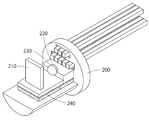
도 2는 일실시예에 따른 TWDM 기반 물리량 측정 장치 중 광원부의 구조를 도시한 도면이다.2 is a diagram illustrating a structure of a light source unit of a TWDM-based physical quantity measuring apparatus according to an exemplary embodiment.
일실시예에 따르면, 광원부(110)는 입력광 생성부, 필터(210), 광증폭기(220), 렌즈(230) 및 냉각기(240)를 포함할 수 있다. 입력광 생성부는 일정한 주기로 구동 신호의 세기를 변경하여 생성된 입력광을 필터(210)로 전달하고, 필터(210)는 입력광의 파장을 변경하여 렌즈(230)로 전달하고, 렌즈(230)는 파장이 변경된 입력광을 집적하여 광증폭기(220)로 전달하고, 광증폭기(220)는 파장이 변경된 입력광의 세기를 증폭하여 광 서큘레이터(120)로 입사광을 방출할 수 있다.According to one embodiment, the
일실시예에 따르면, 입력광 생성부는 일정한 주기로 구동신호의 세기를 변경하여 입력광을 생성하고 이를 필터(210)에 전달할 수 있다. 일정한 주기로 구동 신호의 세기가 변경됨으로써 필터(210)에 입사되는 입력광의 중심 파장은 일정한 간격으로 이동할 수 있다. 따라서, 구동 신호의 세기의 주기적인 변화와 함께 파장 가변 필터(210)에 인가되는 전기적 변화를 통하여 시간-파장 분할 다중화에 기반한 광원이 형성될 수 있다.According to an exemplary embodiment, the input light generator may generate input light by changing the intensity of the driving signal at a predetermined period, and may transmit the input light to the
일실시예에 따르면, 필터(210)는 파장 가변 필터를 포함할 수 있다. 파장 가변 필터는 필터로 입사되는 광의 파장을 변경하는 필터를 의미할 수 있다. 파장 가변 필터는 액정(Liquid crystal, LC) 파장 가변 필터를 포함할 수 있다. 액정 파장 가변 필터는 액정 파장 가변 필터에 인가되는 전기적 변화를 통해 액정의 굴절률을 변경할 수 있고, 변경된 굴절률에 따라 액정은 액정 파장 가변 필터에 입사되는 광의 파장을 변경할 수 있다.According to one embodiment, the
일실시예에 따르면, 광증폭기(220)는 파장이 변경된 입력광의 세기를 증폭할 수 있다. 광증폭기는 반사를 통해 광을 증폭할 수 있다. 예를 들어, 광증폭기는 RSOA (Reflective Semiconductor Optical Amplifeir)를 포함할 수 있다.According to one embodiment, the
일실시예에 따르면, 렌즈(230)는 파장이 변경된 입력광을 집적하여 광증폭기(220)로 전달할 수 있다. 일실시예에 따르면, 냉각기(240)는 온도 변화에 따른 필터(210)의 변화를 완화할 수 있다. 구체적으로, 액정 파장 가변 필터는 온도 변화에 따라 액정의 굴절률이 변화되는 특성을 가지기 때문에, 냉각기(240)는 액정 가변 필터의 온도를 일정 범위 내로 유지할 수 있다. 냉각기(240)는 열 펌프(Heat pump)를 포함할 수 있다. 즉, 냉각기(240)는 저온의 열원으로부터 열을 흡수하여 고온의 열원에 열을 줄 수 있다. 예를 들어, 냉각기(240)는 TEC(ThermoElectric Cooler)를 포함할 수 있다. 여기서, TEC는 열전소자 원리 열전 모듈, Peltier Module, TEM(Thermoe Electric Module)로 지칭될 수 있다. According to one embodiment, the
일실시예에 따르면, 광원부(110)의 각 구성요소는 특정 패키지 안에 집적될 수 있다. 예를 들어, 광원부(110)의 각 구성요소는 TO-can 패키지 내에 집적될 수 있다. TO-can 패키지의 방열 특성을 고려하여, 액정 파장 가변 필터의 온도 의존성을 낮추기 위하여 필터(210)를 포함하는 광원부(110)의 각 구성요소는 도 2에 도시된 바와 같이 TO-can 패키지의 헤더 부분에 집적될 수 있다. 도 2의 TO-can 패키지의 우측 막대 구성은 기판에 TO-can 패키지를 고정하는 리드핀 역할을 할 수 있다.According to one embodiment, each component of the
도 3은 일실시예에 따른 트리거 신호에 따라 필터를 투과한 광의 스펙트럼을 도시한 그래프이다.3 is a graph showing a spectrum of light transmitted through a filter according to a trigger signal according to an embodiment.
도 3에서 사인파 형태의 그래프는 필터(210)를 투과한 입력광의 시간에 따른 세기를 나타낸 것이며, 계단 형태의 그래프는 필터(210)에 인가되는 구동 신호의 시간에 따른 전압을 나타낸 그래프이다.In FIG. 3, a graph of a sinusoidal waveform shows intensity of input light passing through the
구동 신호는 일정 주기 마다 일정한 크기의 전압만큼 상승할 수 있다. 상승된 전압에 따라 필터(210)의 액정의 굴절률은 일정 크기만큼 변화될 수 있다. 변화된 굴절률에 따라 필터(210)를 통과한 입력광의 중심 파장은 일정 간격만큼 이동할 수 있다. 여기서 시간 분할 다중화가 이루어지며, 시간 분할의 기준은 구동 신호의 상승 시간이 될 수 있다.The driving signal can be raised by a constant magnitude voltage at regular intervals. The refractive index of the liquid crystal of the
필터(210)를 투과한 입력광의 파장 범위는 액정 파장 가변 필터의 경우, 액정의 두께와 액정의 특성에 따라 조절될 수 있으며, 센서(130)에 포함된 광섬유 격자의 파장 범위를 제한한다. 광섬유 브래그 격자의 경우, 파장 범위는 브래그 대역에 대응될 수 있다.In the case of a liquid crystal wavelength variable filter, the wavelength range of the input light transmitted through the
한편, 도 1의 데이터처리부(150)는 신호변환부(140)로부터 수신된 전기적 신호로부터 반사광의 파장 변화를 검출할 수 있다. 반사광의 파장 변화는 센서(130)가 감지한 물리량의 변화를 반영하고 있으므로, 데이터처리부(150)는 반사광의 파장 변화로부터 물리량을 측정할 수 있다. 여기서, 반사광의 파장과 입력광의 파장을 동기화하기 위하여, 광원부(110)의 구동 신호가 사용될 수 있다. 즉, 입력광의 시간 분할 기준이 동기화에 사용될 수 있다.The
도 4는 일실시예에 따른 시간에 따라 중심 파장의 위치가 변화된 광의 스펙트럼에 대응하는 광섬유 격자로부터 반사된 광의 중심 파장 변화를 도시한 그래프이다.FIG. 4 is a graph showing a change in the center wavelength of light reflected from an optical fiber grating corresponding to a spectrum of light whose center wavelength position is changed with time according to an embodiment.
도 1의 데이터처리부(150)는 신호변환부(140)로부터 수신된 전기적 신호로부터 반사광의 파장 변화를 검출할 수 있다. 반사광의 파장 변화는 센서(130)가 감지한 물리량의 변화를 반영하고 있으므로, 데이터처리부(150)는 반사광의 파장 변화로부터 물리량을 측정할 수 있다. 구체적으로, 반사광의 파장 변화로부터 반사광의 세기가 검출될 수 있고, 이로부터 물리량이 측정될 수 있다. The
광섬유 브래그 격자는 특정 물리량에 민감하도록 형성될 수 있다. 물리량이 변화되는 경우 광섬유 브래그 격자의 미세구조의 주기가 변경될 수 있고, 이에 따라 반사광에 대응되는 브래그 대역이 변경될 수 있다. 따라서 반사광의 파장 변화를 통해 물리량이 측정될 수 있는 것이다.The fiber Bragg grating may be formed to be sensitive to certain physical quantities. When the physical quantity is changed, the period of the microstructure of the optical fiber Bragg grating can be changed, and accordingly, the Bragg band corresponding to the reflected light can be changed. Therefore, the physical quantity can be measured through the wavelength change of the reflected light.
도 2의 필터(210)를 투과한 입력광의 스펙트럼들은 도 4에서 각각 t0와 t1 시각의 구동 신호에 대응된다. 도 4는 도 1의 센서(130)가 광섬유 브래그 격자를 포함하는 경우를 가정한 것이며, FBG1은 t0 시각에 대응하는 반사광에 대한 스펙트럼이며, FBG2는 t1 시각에 대응하는 반사광에 대한 스펙트럼이다. 그래프의 가로축은 파장을 나타내며, 세로축은 진폭을 나타내므로, 도 4는 필터를 투과한 광 및 반사광의 파장에 따른 진폭의 변화를 나타낸다. 여기서 필터를 투과한 광이란 도 1의 광원부(110) 내에서 필터를 투과한 후의 입력광을 지칭할 수 있다.The spectra of the input light transmitted through the
도 1의 데이터처리부(150)는 t0 시각에서 FBG1의 파장 변화로부터 반사광의 세기를 검출할 수 있으며, t1 시각에서 FBG2의 파장 변화로부터 반사광의 세기를 검출할 수 있다. 이때, t0와 t1은 광원부(110)의 구동 신호의 임의의 인접한 주기에서의 상승 시각에 대응할 수 있고, 데이터처리부(150)는 구동 신호를 이용하여 반사광의 스펙트럼을 필터를 투과한 입력광에 동기화할 수 있다. 도 4의 검출된 광의 스펙트럼은 검출된 반사광의 세기에 대응될 수 있다.The
구체적으로, 도 1의 데이터처리부(150)는 필터를 투과한 입력광의 기울기에서 특정 위치 및 범위에서 존재하는 광섬유 격자센서의 파장의 변화를 광 세기 변화로 변환할 수 있다. 도 1의 광원부(110)에 의해 파장 분할 다분화뿐만 아니라 시간 분할 다분화도 구현되므로, 데이터처리부(150)는 반사광의 파장 변화로부터 온도변화와 같은 저속의 물리량 변화뿐만 아니라, 진동이나 충격량 같은 고속의 물리량 변화도 쉽게 검출할 수 있다. Specifically, the
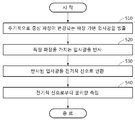
도 5는 일실시예에 따른 TWDM 기반 물리량 측정 방법을 도시한 순서도이다.FIG. 5 is a flowchart illustrating a TWDM-based physical quantity measurement method according to an embodiment.
단계(510)에서, 도 1의 물리량 측정 장치(100)는 일정한 주기로 중심 파장이 변경되고 각 주기 내에서 전기적 변화를 통해 파장이 변경되는 입사광을 방출할 수 있다. 구체적으로, 물리량 측정 장치(100)는 도 2의 필터(210)의 트리거 신호를 주기적으로 변경함으로써 시간-파장 분할 다중화(TWDM)를 동시에 구현할 수 있다. TWDM 기반 입사광을 이용하여 도 1의 센서(130)에 포함된 광섬유 격자 센서로부터 반사된 반사광을 분석하여, 물리량 측정 장치(100)는 온도, 스트레인과 같은 저속의 물리량뿐만 아니라, 전압, 진동과 같은 고속의 물리량을 포함한 다양한 물리량을 측정할 수 있다.In
단계(520)에서, 물리량 측정 장치(100) 입사광 중에서 특정 파장을 가지는 입사광을 반사할 수 있다. 구체적으로, 도 1의 센서(130)는 광섬유 격자를 포함할 수 있고, 광섬유 격자의 격자 조건을 만족하는 파장을 반사할 수 있다. 광섬유 브래그 격자의 미세구조의 주기는 광섬유에 가해지는 물리량의 변화에 의해 변화될 수 있다. 브래그 대역은 미세구조의 주기와 코어의 굴절률에 의해 결정될 수 있으므로, 물리량의 변화에 의해 브래그 대역을 만족하는 입력광의 선택이 달라질 수 있다. 즉, 물리량의 변화에 의해 반사광의 파장이 변경될 수 있다.In
단계(530)에서, 물리량 측정 장치(100)는 반사된 입사광을 전기적 신호로 변환할 수 있다. 즉, 물리량 측정 장치(100)는 도 1의 데이터처리부(150)가 해석할 수 있는 형태인 전기적 신호로 광 신호를 변환하기 위하여 반사광을 광전변환할 수 있다.In
단계(540)에서, 물리량 측정 장치(100)는 전기적 신호로부터 물리량을 측정할 수 있다. 구체적으로, 물리량 측정 장치(100)는 전기 신호를 해독하기 위하여 디지털 신호로 변환한 후, 디지털 신호로부터 물리량을 측정할 수 있다. 이때, 물리량 측정 장치(100)는 반사광의 파장 변화로부터 반사광의 세기가 검출할 수 있고, 이로부터 물리량을 측정할 수 있다.In
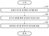
도 6은 일실시예에 따른 TWDM 기반 입사광 생성 방법을 도시한 순서도이다.6 is a flowchart illustrating a TWDM-based incident light generating method according to an embodiment.
단계(610)에서 도 1의 광원부(110)는 일정한 주기로 구동 신호의 세기를 변경하여 입력광을 생성할 수 있다. 구체적으로, 일정한 주기로 구동 신호의 세기가 변경됨으로써 도 2의 필터(210)에 입사되는 입력광의 중심 파장은 일정한 간격으로 이동할 수 있다. 따라서, 구동 신호의 세기의 주기적인 변화와 함께 파장 가변 필터(210)에 인가되는 전기적 변화를 통하여 시간-파장 분할 다중화에 기반한 광원이 형성될 수 있다.In
단계(620)에서 광원부(110)는 전기적 변화를 통해 입력광의 파장을 변경할 수 있다. 구체적으로, 광원부(110)는 파장 가변 필터를 포함할 수 있고, 예를 들어 액정(Liquid crystal, LC) 파장 가변 필터를 포함할 수 있다. 액정 파장 가변 필터는 액정 파장 가변 필터에 인가되는 전기적 변화를 통해 액정의 굴절률을 변경할 수 있고, 변경된 굴절률에 따라 액정은 액정 파장 가변 필터에 입사되는 광의 파장을 변경할 수 있다.In
단계(630)에서 광원부(110)는 파장이 변경된 입력광의 세기를 증폭하여 입사광을 방출할 수 있다. 구체적으로, 광원부(110)는 반사를 통해 광을 증폭할 수 있다.In
이상과 같이 실시예들이 비록 한정된 실시예와 도면에 의해 설명되었으나, 해당 기술분야에서 통상의 지식을 가진 자라면 상기의 기재로부터 다양한 수정 및 변형이 가능하다. 예를 들어, 설명된 기술들이 설명된 방법과 다른 순서로 수행되거나, 및/또는 설명된 장치, 구조, 장치, 회로 등의 구성요소들이 설명된 방법과 다른 형태로 결합 또는 조합되거나, 다른 구성요소 또는 균등물에 의하여 대치되거나 치환되더라도 적절한 결과가 달성될 수 있다.While the present invention has been particularly shown and described with reference to exemplary embodiments thereof, it is to be understood that the invention is not limited to the disclosed exemplary embodiments. For example, it should be understood that the techniques described may be performed in a different order than the described methods, and / or that components of the described devices, structures, devices, circuits, Lt; / RTI > or equivalents, even if it is replaced or replaced.
그러므로, 다른 구현들, 다른 실시예들 및 특허청구범위와 균등한 것들도 후술하는 특허청구범위의 범위에 속한다.Therefore, other implementations, other embodiments, and equivalents to the claims are also within the scope of the following claims.
100: 물리량 측정 장치
110: 광원부
120: 광 서큘레이터
130: 센서
140: 신호변환부
150: 데이터처리부
160: 파장 검출 동기 신호100: Physical measurement device
110: light source
120: Optical circulator
130: sensor
140: Signal conversion section
150:
160: Wavelength detection synchronizing signal
Claims (14)
전기적 변화를 통해 상기 입력광의 파장을 변경하는 필터; 및
상기 파장이 변경된 입력광의 세기를 증폭하여 입사광을 방출하는 광증폭기
를 포함하는 입사광 생성 장치.
An input light generator for generating input light by changing the intensity of the driving signal at a constant cycle;
A filter for changing a wavelength of the input light through an electrical change; And
An optical amplifier for amplifying the intensity of the input light having the changed wavelength and emitting an incident light,
And a light source.
상기 입력광 생성부는,
상기 일정한 주기마다 상기 구동 신호의 세기를 변경함으로써 상기 입력광의 중심 파장을 변경하는 입사광 생성 장치.
The method according to claim 1,
Wherein the input light generator comprises:
Wherein the central wavelength of the input light is changed by changing the intensity of the driving signal at every predetermined period.
상기 필터는,
상기 전기적 변화를 통해 상기 필터의 굴절률을 변경하고, 상기 변경된 굴절률을 통해 상기 입력광의 파장을 변경하는 입사광 생성 장치.
The method according to claim 1,
The filter includes:
Wherein the refractive index of the filter is changed through the electrical change and the wavelength of the input light is changed through the changed refractive index.
상기 파장이 변경된 입력광을 집적하여 상기 광증폭기로 전달하는 렌즈
를 더 포함하는 입사광 생성 장치.
The method according to claim 1,
A lens for collecting input light having the changed wavelength and delivering it to the optical amplifier
Further comprising:
상기 필터에 인접하고 상기 필터의 온도를 일정하게 유지하기 위한 냉각기
를 더 포함하는 입사광 생성 장치.
The method according to claim 1,
A cooler for keeping the temperature of the filter constant,
Further comprising:
상기 입사광 중에서 특정 파장을 가지는 입사광을 반사하는 센서;
상기 반사된 입사광을 전기적 신호로 변환하는 신호변환부; 및
상기 전기적 신호로부터 물리량을 측정하는 데이터처리부
를 포함하는 물리량 측정 장치.
A light source portion which emits incident light whose center wavelength is changed in a constant cycle and whose wavelength is changed through an electrical change within each period;
A sensor for reflecting incident light having a specific wavelength among the incident light;
A signal converter for converting the reflected incident light into an electrical signal; And
A data processing unit for measuring a physical quantity from the electrical signal;
And a physical quantity measuring device.
상기 광원부는,
상기 일정한 주기로 구동 신호의 세기를 변경하는 입력광 생성부;
상기 전기적 변화를 통해 상기 입력광의 파장을 변경하는 필터; 및
상기 파장이 변경된 입력광의 세기를 증폭하여 상기 입사광을 방출하는 광증폭기를 포함하고,
상기 입력광의 파장이 변경됨으로써 상기 입사광의 파장이 변경되는,
물리량 측정 장치.
The method according to claim 6,
The light source unit includes:
An input light generator for changing the intensity of the driving signal at the predetermined period;
A filter for changing a wavelength of the input light through the electrical change; And
And an optical amplifier for amplifying the intensity of the input light having the changed wavelength to emit the incident light,
Wherein a wavelength of the incident light is changed by changing a wavelength of the input light,
A physical quantity measuring device.
상기 입력광 생성부는,
상기 일정한 주기마다 상기 구동 신호의 세기를 변경하여 상기 입력광의 중심 파장을 변경함으로써 상기 입사광의 중심 파장을 변경하는 물리량 측정 장치.
8. The method of claim 7,
Wherein the input light generator comprises:
Wherein the center wavelength of the incident light is changed by changing the intensity of the driving signal by changing the center wavelength of the input light at every predetermined period.
상기 센서는,
상기 입사광 중에서 격자 조건을 만족하는 파장을 가지는 입사광을 반사하는 광섬유 격자를 포함하는 물리량 측정 장치.
The method according to claim 6,
The sensor includes:
And an optical fiber grating that reflects incident light having a wavelength satisfying a lattice condition among the incident light.
상기 데이터 처리부는 상기 주기를 이용하여 상기 전기적 신호를 동기화함으로써 물리량을 측정하는 물리량 측정 장치.
The method according to claim 6,
And the data processing unit measures the physical quantity by synchronizing the electrical signal using the period.
상기 중심 파장의 오차를 보정하는 보정부
를 더 포함하는 물리량 측정 장치.
The method according to claim 6,
A correction unit for correcting an error of the center wavelength,
Further comprising:
상기 광원부로부터 수신된 상기 입사광의 방향을 상기 필터로 변경하고, 상기 필터로부터 수신된 상기 반사된 입사광의 방향을 상기 신호변환부로 변경하는 광 서큘레이터
를 더 포함하는 물리량 측정 장치.
The method according to claim 6,
An optical circulator that changes the direction of the incident light received from the light source unit to the filter and changes the direction of the reflected incident light received from the filter to the signal conversion unit,
Further comprising:
전기적 변화를 통해 상기 입력광의 파장을 변경하는 단계; 및
상기 파장이 변경된 입력광의 세기를 증폭하여 입사광을 방출하는 단계
를 포함하는 입사광 생성 방법.
Generating input light by changing the intensity of the driving signal at a constant cycle;
Changing a wavelength of the input light through an electrical change; And
Amplifying the intensity of the input light having the changed wavelength to emit incident light
≪ / RTI >
상기 입사광 중에서 특정 파장을 가지는 입사광을 반사하는 단계;
상기 반사된 입사광을 전기적 신호로 변환하는 단계;
상기 전기적 신호로부터 물리량을 측정하는 단계
를 포함하는 물리량 측정 방법. Emitting an incident light whose center wavelength is changed in a constant period and whose wavelength is changed through an electrical change in each period;
Reflecting incident light having a specific wavelength from the incident light;
Converting the reflected incident light into an electrical signal;
Measuring a physical quantity from the electrical signal
And measuring the physical quantity.
Priority Applications (2)
| Application Number | Priority Date | Filing Date | Title |
|---|---|---|---|
| KR1020160005885A KR20170086264A (en) | 2016-01-18 | 2016-01-18 | Aparatus and method for measuring physical quantitiy based on time and wavelegnth division multiplexing |
| US15/408,260 US20170205254A1 (en) | 2016-01-18 | 2017-01-17 | Method and apparatus for measuring physical quantity based on time and wavelength division multiplexing (twdm) |
Applications Claiming Priority (1)
| Application Number | Priority Date | Filing Date | Title |
|---|---|---|---|
| KR1020160005885A KR20170086264A (en) | 2016-01-18 | 2016-01-18 | Aparatus and method for measuring physical quantitiy based on time and wavelegnth division multiplexing |
Publications (1)
| Publication Number | Publication Date |
|---|---|
| KR20170086264A true KR20170086264A (en) | 2017-07-26 |
Family
ID=59313665
Family Applications (1)
| Application Number | Title | Priority Date | Filing Date |
|---|---|---|---|
| KR1020160005885A KR20170086264A (en) | 2016-01-18 | 2016-01-18 | Aparatus and method for measuring physical quantitiy based on time and wavelegnth division multiplexing |
Country Status (2)
| Country | Link |
|---|---|
| US (1) | US20170205254A1 (en) |
| KR (1) | KR20170086264A (en) |
Families Citing this family (1)
| Publication number | Priority date | Publication date | Assignee | Title |
|---|---|---|---|---|
| US11906369B2 (en) * | 2021-09-22 | 2024-02-20 | Kidde Technologies, Inc. | Overheat detection with clamp health monitoring |
Family Cites Families (23)
| Publication number | Priority date | Publication date | Assignee | Title |
|---|---|---|---|---|
| US6867888B2 (en) * | 1996-07-12 | 2005-03-15 | Science Applications International Corporation | Switchable polymer-dispersed liquid crystal optical elements |
| US5917597A (en) * | 1998-02-04 | 1999-06-29 | Litton Systems, Inc. | Noise suppression apparatus and method for time division multiplexed fiber optic sensor arrays |
| CA2335469C (en) * | 1998-06-26 | 2009-06-09 | Cidra Corporation | Non-intrusive fiber optic pressure sensor for measuring unsteady pressures within a pipe |
| US6466706B1 (en) * | 2000-10-11 | 2002-10-15 | The United States Of America As Represented By The Secretary Of The Navy | Pulsed system and method for fiber optic sensor |
| US6865315B2 (en) * | 2001-08-29 | 2005-03-08 | Jds Uniphase Corporation | Dispersion compensating filters |
| US6839488B2 (en) * | 2001-09-10 | 2005-01-04 | California Institute Of Technology | Tunable resonant cavity based on the field effect in semiconductors |
| JP3999012B2 (en) * | 2002-03-22 | 2007-10-31 | 富士通株式会社 | Control method and control device for wavelength tunable optical filter |
| GB0302434D0 (en) * | 2003-02-03 | 2003-03-05 | Sensor Highway Ltd | Interferometric method and apparatus for measuring physical parameters |
| GB0409865D0 (en) * | 2004-05-01 | 2004-06-09 | Sensornet Ltd | Direct measurement of brillouin frequency in distributed optical sensing systems |
| CA2593986C (en) * | 2004-12-16 | 2014-01-28 | Vectronix Ag | Not temperature stabilized pulsed laser diode and all fibre power amplifier |
| US7310464B2 (en) * | 2005-06-21 | 2007-12-18 | Litton Systems, Inc. | Multi-wavelength optical source |
| US8379297B2 (en) * | 2006-05-30 | 2013-02-19 | Weatherford/Lamb, Inc. | Wavelength swept light source and filter based on sweep function, and its method of operation |
| US7974534B2 (en) * | 2006-08-11 | 2011-07-05 | Purdue Research Foundation | Wideband microwave and millimeter wave filters using photonic spectral filtering |
| US8787771B2 (en) * | 2006-10-06 | 2014-07-22 | Ciena Corporation | All-optical regenerator and optical network incorporating same |
| WO2008093448A1 (en) * | 2007-01-29 | 2008-08-07 | Optical Comb, Inc. | Wavelength scanning light source and optical coherence tomography device |
| US20090059209A1 (en) * | 2007-09-05 | 2009-03-05 | An-Dien Nguyen | Lock-in demodulation technique for optical interrogation of a grating sensor |
| US8582619B2 (en) * | 2011-03-15 | 2013-11-12 | Lightlab Imaging, Inc. | Methods, systems, and devices for timing control in electromagnetic radiation sources |
| GB2489749B (en) * | 2011-04-08 | 2016-01-20 | Optasense Holdings Ltd | Fibre optic distributed sensing |
| CN102621764B (en) * | 2011-11-23 | 2014-07-02 | 深圳大学 | Ultrasonic grating based tunable optical frequency converter |
| US20140043614A1 (en) * | 2012-06-28 | 2014-02-13 | Technion Research And Development Foundation Ltd. | On-fiber optomechanical cavity based sensor |
| KR101788540B1 (en) * | 2013-08-12 | 2017-10-20 | 한국전자통신연구원 | Optical transmitter module with temperature device and method of manufacturing the same |
| JP6213293B2 (en) * | 2014-02-18 | 2017-10-18 | ソニー株式会社 | Semiconductor laser device assembly |
| KR20150145124A (en) * | 2014-06-18 | 2015-12-29 | 한국전자통신연구원 | Bi-directional optical transceiver module and the aligning method thereof |
-
2016
- 2016-01-18 KR KR1020160005885A patent/KR20170086264A/en unknown
-
2017
- 2017-01-17 US US15/408,260 patent/US20170205254A1/en not_active Abandoned
Also Published As
| Publication number | Publication date |
|---|---|
| US20170205254A1 (en) | 2017-07-20 |
Similar Documents
| Publication | Publication Date | Title |
|---|---|---|
| US9810556B2 (en) | Apparatus for measuring optical signals from multiple optical fiber sensors | |
| US6674928B2 (en) | Optical sensing device containing fiber Bragg gratings | |
| US9310273B2 (en) | Optical fibre sensor interrogation system | |
| Wang et al. | Multiplexed fiber Fabry–Perot interferometer sensors based on ultrashort Bragg gratings | |
| US10731969B2 (en) | In-line fiber sensing, noise cancellation and strain detection | |
| WO1998036252A1 (en) | Device for measurement of optical wavelengths | |
| CA2899044C (en) | Multi-peak reference grating | |
| WO2005024349A1 (en) | Fiber bragg grating sensor system | |
| GB2409517A (en) | Wavelength reference system for fibre Bragg sensor | |
| US9164027B2 (en) | Frequency tunable laser system | |
| JP5168700B2 (en) | Wavelength detection type optical fiber sensor system | |
| CN105806374A (en) | Fiber bragg grating wavelength demodulation method | |
| Zhu et al. | Fabry–Perot sensor using cascaded chirped fiber Bragg gratings with opposite chirp directions | |
| CA2972641C (en) | Birefringent multi-peak optical reference element and birefringent sensor system | |
| Xia et al. | TDM interrogation of identical weak FBGs network based on delayed laser pulses differential detection | |
| KR20170086264A (en) | Aparatus and method for measuring physical quantitiy based on time and wavelegnth division multiplexing | |
| Zhao et al. | Fiber Bragg grating sensor interrogation using chirped fiber grating-based Sagnac loop | |
| RU2602998C1 (en) | Method of controlling spectral parameters fibre bragg grating | |
| JP5219166B2 (en) | Wavelength detection type fiber sensor system | |
| IT202000002956A1 (en) | HIGH SAMPLING SPEED FIBER OPTICAL SENSOR | |
| JP2007205783A (en) | Reflection spectrum measurement system | |
| Ni et al. | A high efficient method for demodulation of FBG sensors | |
| Liu et al. | Fiber-Bragg-grating cavity sensor interrogated with a self-seeded Fabry-Perot laser diode | |
| RU2520963C2 (en) | Optic fibre measuring system (versions) | |
| Lloyd et al. | A high-performance miniaturized time division multiplexed sensor system for remote structural health monitoring |