KR20170080351A - A touch sensor integrated type display device - Google Patents
A touch sensor integrated type display device Download PDFInfo
- Publication number
- KR20170080351A KR20170080351A KR1020150191825A KR20150191825A KR20170080351A KR 20170080351 A KR20170080351 A KR 20170080351A KR 1020150191825 A KR1020150191825 A KR 1020150191825A KR 20150191825 A KR20150191825 A KR 20150191825A KR 20170080351 A KR20170080351 A KR 20170080351A
- Authority
- KR
- South Korea
- Prior art keywords
- touch
- gain
- points
- sensing
- driver
- Prior art date
Links
Images


Classifications
-
- G—PHYSICS
- G06—COMPUTING; CALCULATING OR COUNTING
- G06F—ELECTRIC DIGITAL DATA PROCESSING
- G06F3/00—Input arrangements for transferring data to be processed into a form capable of being handled by the computer; Output arrangements for transferring data from processing unit to output unit, e.g. interface arrangements
- G06F3/01—Input arrangements or combined input and output arrangements for interaction between user and computer
- G06F3/03—Arrangements for converting the position or the displacement of a member into a coded form
- G06F3/041—Digitisers, e.g. for touch screens or touch pads, characterised by the transducing means
- G06F3/044—Digitisers, e.g. for touch screens or touch pads, characterised by the transducing means by capacitive means
-
- G—PHYSICS
- G06—COMPUTING; CALCULATING OR COUNTING
- G06F—ELECTRIC DIGITAL DATA PROCESSING
- G06F3/00—Input arrangements for transferring data to be processed into a form capable of being handled by the computer; Output arrangements for transferring data from processing unit to output unit, e.g. interface arrangements
- G06F3/01—Input arrangements or combined input and output arrangements for interaction between user and computer
- G06F3/03—Arrangements for converting the position or the displacement of a member into a coded form
- G06F3/041—Digitisers, e.g. for touch screens or touch pads, characterised by the transducing means
- G06F3/0416—Control or interface arrangements specially adapted for digitisers
- G06F3/0418—Control or interface arrangements specially adapted for digitisers for error correction or compensation, e.g. based on parallax, calibration or alignment
-
- G—PHYSICS
- G06—COMPUTING; CALCULATING OR COUNTING
- G06F—ELECTRIC DIGITAL DATA PROCESSING
- G06F2203/00—Indexing scheme relating to G06F3/00 - G06F3/048
- G06F2203/041—Indexing scheme relating to G06F3/041 - G06F3/045
- G06F2203/04104—Multi-touch detection in digitiser, i.e. details about the simultaneous detection of a plurality of touching locations, e.g. multiple fingers or pen and finger
Landscapes
- Engineering & Computer Science (AREA)
- General Engineering & Computer Science (AREA)
- Theoretical Computer Science (AREA)
- Human Computer Interaction (AREA)
- Physics & Mathematics (AREA)
- General Physics & Mathematics (AREA)
- Position Input By Displaying (AREA)
- Control Of Indicators Other Than Cathode Ray Tubes (AREA)
Abstract
본 발명은 픽셀 어레이에 내장되는 다수의 터치 센서들을 포함한 표시패널과, 터치 센서들로부터 수신되는 터치 센싱값들 중에서 기설정된 기준값보다 높은 터치 센싱값을 가지는 터치 포인트의 수를 카운팅하고, 카운팅된 터치 포인트의 수에 따라 터치 게인을 조정하는 터치 구동부를 포함한다.The present invention relates to a display device including a display panel including a plurality of touch sensors built in a pixel array, a display panel for counting the number of touch points having a touch sensing value higher than a preset reference value among touch sensing values received from the touch sensors, And a touch driver for adjusting the touch gain according to the number of points.
Description
본 발명은 터치 센서 내장형 표시장치에 관한 것이다.The present invention relates to a touch sensor built-in display device.
유저 인터페이스(User Interface, UI)는 사람(사용자)과 각종 전기, 전자 기기 등의 통신을 가능하게 하여 사용자가 기기를 쉽게 자신이 원하는 대로 제어할 수 있게 한다. 이러한 유저 인터페이스의 대표적인 예로는 키패드, 키보드, 마우스, 온스크린 디스플레이(On Screen Display, OSD), 적외선 통신 혹은 고주파(RF) 통신 기능을 갖는 원격 제어기(Remote controller) 등이 있다. 유저 인터페이스 기술은 사용자 감성과 조작 편의성을 높이는 방향으로 발전을 거듭하고 있다. 최근, 유저 인터페이스는 터치 UI, 음성 인식 UI, 3D UI 등으로 진화되고 있으며, 터치 UI는 휴대용 정보기기에 기본적으로 설치되고 있는 추세에 있다. 터치 UI를 구현하기 위하여, 가전기기나 휴대용 정보기기의 표시소자 상에 터치 스크린이 설치된다.A user interface (UI) enables communication between a person (user) and various electric or electronic devices, allowing a user to easily control the device as desired. Representative examples of such a user interface include a keypad, a keyboard, a mouse, an on screen display (OSD), a remote controller having infrared communication or radio frequency (RF) communication function, and the like. User interface technology has been developed to enhance the user's sensibility and ease of operation. In recent years, the user interface has evolved into a touch UI, a voice recognition UI, a 3D UI, and the like, and the touch UI is basically installed in a portable information device. To implement the touch UI, a touch screen is installed on a display element of a home appliance or a portable information device.
정전 용량 방식의 터치 스크린은 기존의 저항막 방식에 비하여 내구성과 선명도가 높고, 멀티 터치 인식과 근접 터치 인식이 가능하여 다양한 어플리케이션에 적용될 수 있는 장점이 있다. 정전 용량 방식은 상호 용량을 터치 센서로 활용하는 상호 용량 방식(mutual capacitance type)과 자기 용량을 터치 센서로 활용하는 자기 용량 방식(self capacitance type)이 있다. 자기 용량 방식은 터치 센서로부터 입력되는 터치 데이터에 터치 게인을 적용한 출력 데이터를 출력하였다. 여기서 터치 게인은 미리 설정된 값이다.The capacitive touch screen has higher durability and sharpness than the conventional resistive touch screen, and has multi-touch recognition and proximity touch recognition, which can be applied to various applications. The electrostatic capacitance type has a mutual capacitance type in which mutual capacitance is used as a touch sensor and a self capacitance type in which a magnetic capacitance is used as a touch sensor. The magneto-capacitance method outputs the output data obtained by applying the touch gain to the touch data input from the touch sensor. Here, the touch gain is a preset value.
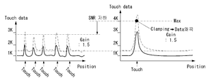
터치 데이터는 터치 센서에 터치되는 터치 포인트의 수에 따라 변화된다. 도 1에 도시된 바와 같이, 터치 포인트가 싱글인 경우에는 터치 데이터가 3K의 값을 가지나, 터치 포인트가 멀티인 경우에는 터치 데이터가 1K 내지 2K 사이의 값을 가진다. 즉, 터치 포인트가 많아질수록 터치 감도가 낮아진다.The touch data is changed according to the number of touch points touched by the touch sensor. As shown in FIG. 1, when the touch point is single, the touch data has a value of 3K. When the touch point is multi, the touch data has a value between 1K and 2K. That is, as the number of touch points increases, the touch sensitivity decreases.
도 2에 도시된 바와 같이, 터치 포인트가 싱글 터치인 경우를 기준으로 터치 게인을 고정할 경우, 터치 게인은 낮은 게인 값을 가진다. 낮은 게인 값을 가지는 터치 게인을 멀티 터치에 적용하면 터치 데이터 출력이 작아 상대적으로 터치감도가 떨어진다.As shown in FIG. 2, when the touch gain is fixed based on the case where the touch point is a single touch, the touch gain has a low gain value. When touch gain with low gain value is applied to multi touch, the touch data output is small and the touch sensitivity is relatively low.
이와 반대로 터치 포인트가 멀티 터치인 경우를 기준으로 터치 게인을 고정할 경우, 터치 게인은 높은 게인 값을 가진다. 높은 게인 값을 가지는 터치 게인을 싱글 터치인 경우에 적용하면, 터치 데이터 출력이 커져 터치 데이터 전압의 최대치를 초과한다. 이에 왜곡이 발생되어 터치 감도가 떨어진다.On the contrary, when the touch gain is fixed based on the case where the touch point is multi-touch, the touch gain has a high gain value. If the touch gain having a high gain value is applied to a case of a single touch, the touch data output increases and exceeds the maximum value of the touch data voltage. Distortion is generated and the touch sensitivity is reduced.
상술한 바와 같이, 종래에는 싱글 터치일 때와 멀티 터치일 때 모두 동일한 터치 게인을 적용하였기 때문에, 각각의 상황에서 터치 감도의 차이가 발생하는 문제가 있었다.As described above, conventionally, since the same touch gain is applied to both a single touch and a multi-touch, a difference in touch sensitivity occurs in each situation.
본 발명의 목적은 프레임별 터치 포인트의 수에 따라 터치 게인을 조정하여 터치감도가 저하되는 것을 방지할 수 있도록 한 터치 센서 내장형 표시장치를 제공하는 데 있다.SUMMARY OF THE INVENTION It is an object of the present invention to provide a touch sensor built-in display device capable of preventing touch sensitivity from being degraded by adjusting a touch gain according to the number of touch points per frame.
상기 목적을 달성하기 위하여, 본 발명은 픽셀 어레이에 내장되는 다수의 터치 센서들을 포함한 표시패널과, 터치 센서들로부터 수신되는 터치 센싱값들 중에서 기설정된 기준값보다 높은 터치 센싱값을 가지는 터치 포인트의 수를 카운팅하고, 카운팅된 터치 포인트의 수에 따라 터치 게인을 조정하는 터치 구동부를 포함한다.According to an aspect of the present invention, there is provided a display device including a display panel including a plurality of touch sensors incorporated in a pixel array, a display panel including a plurality of touch points having a touch sensing value higher than a predetermined reference value among touch sensing values received from the touch sensors, And a touch driver for adjusting the touch gain according to the counted number of touch points.
터치 구동부는 제1 프레임에서 터치 포인트의 수에 따라 터치 게인을 조정하고, 조정된 터치 게인을 제1 프레임에 이은 제2 프레임의 터치 센싱값들에 적용할 수 있다.The touch driver may adjust the touch gain according to the number of touch points in the first frame and apply the adjusted touch gain to the touch sensing values of the second frame following the first frame.
터치 구동부는 터치 센싱값들을 메모리에 저장하고, 터치 포인트의 수에 따라 터치 게인을 조정한 후 조정된 터치 게인을 메모리로부터 읽어낸 터치 센싱값들에 적용할 수 있다.The touch driver may store the touch sensing values in a memory, adjust the touch gain according to the number of touch points, and apply the adjusted touch gain to the touch sensing values read from the memory.
터치 구동부는 터치 센서들로부터 수신되는 터치 센싱값을 센싱하는 센싱유닛과 터치 센싱값들을 기설정된 기준값과 비교하는 비교부와 비교부를 통해 터치 센싱값들 중 기준값보다 높은 센싱 값을 가지는 터치 포인트의 수를 카운팅하는 카운터부와 터치 포인트의 수에 따라 터치 게인을 조정하는 게인조정부를 포함할 수 있다.The touch driver includes a sensing unit for sensing a touch sensing value received from the touch sensors, a comparing unit for comparing the touch sensing values with predetermined reference values, and a comparator for comparing the touch sensing values with a predetermined number of touch points And a gain adjusting unit for adjusting the touch gain according to the number of touch points.
카운터부는 하나의 프레임이 끝날 때마다 초기화될 수 있다.The counter can be initialized at the end of each frame.
본 발명은 프레임별 터치 포인트의 수에 따라 터치 게인을 조정하여 터치감도가 저하되는 것을 방지할 수 있는 효과가 있다.The present invention has the effect of preventing the touch sensitivity from being lowered by adjusting the touch gain according to the number of touch points per frame.
본 발명은 프레임별 터치 포인트의 수에 따라 터치 게인을 조정하여 터치감도가 저하되는 것을 방지함으로써, 제품의 신뢰성을 향상시킬 수 있는 효과가 있다.The present invention has the effect of improving the reliability of the product by preventing the touch sensitivity from being lowered by adjusting the touch gain according to the number of touch points per frame.
도 1은 종래에서 싱글 터치일 때의 터치 센싱값과 멀티 터치일 때의 터치 센싱값을 보여주는 도면.
도 2는 종래에서 싱글 터치일 때의 터치 센싱값과 멀티 터치일 때의 터치 센싱값에 고정된 터치 게인이 적용되는 것을 보여주는 도면.
도 3은 본 발명의 실시 예에 따른 표시장치를 보여주는 도면.
도 4는 픽셀 어레이에 내장된 터치 센서의 일 예를 보여 주는 도면.
도 5는 본 발명의 시분할 구동에 따른 디스플레이 구동 기간과 터치 센서 구동 기간에서 터치 센서, 데이터라인 및 게이트라인에 공급되는 신호들을 보여 주는 파형도.
도 6은 터치 센서들에 연결되는 멀티플렉서들과 센싱 유닛들을 보여주는 도면.
도 7은 본 발명의 실시 예에 따른 터치 구동부의 구성을 보여준다.
도 8은 도 7의 터치 구동부의 구동동작을 순서대로 보여주는 도면.
도 9는 본 발명에 따라 프레임별로 조정된 터치 게인이 적용된 것을 보여주는 도면.
도 10은 본 발명에 따른 싱글 터치일 때의 터치 센싱값과 멀티 터치일 때의 터치 센싱값을 보여주는 도면.1 is a view showing a touch sensing value when a single touch and a touch sensing value when a touch is multi-touch.
FIG. 2 is a diagram showing a touch gain fixed to a touch sensing value when a single touch and a touch sensing value when a multi-touch is applied.
3 is a view showing a display device according to an embodiment of the present invention.
4 is a view showing an example of a touch sensor built in a pixel array.
5 is a waveform diagram showing signals supplied to a touch sensor, a data line, and a gate line in a display driving period and a touch sensor driving period according to the time division driving method of the present invention.
6 shows multiplexers and sensing units connected to touch sensors;
FIG. 7 shows a configuration of a touch driver according to an embodiment of the present invention.
FIG. 8 is a diagram showing a driving operation of the touch driver of FIG. 7 in order; FIG.
9 is a view showing application of a touch gain adjusted for each frame according to the present invention.
FIG. 10 is a diagram showing a touch sensing value when a single touch and a touch sensing value when a multi-touch according to the present invention. FIG.
이하 첨부된 도면을 참조하여 본 발명에 따른 바람직한 실시 예들을 상세히 설명한다. 명세서 전체에 걸쳐서 동일한 참조번호들은 실질적으로 동일한 구성요소들을 의미한다. 이하의 설명에서, 본 발명과 관련된 공지 기능 혹은 구성에 대한 구체적인 설명이 본 발명의 요지를 불필요하게 흐릴 수 있다고 판단되는 경우, 그 상세한 설명을 생략한다.DETAILED DESCRIPTION OF THE PREFERRED EMBODIMENTS Reference will now be made in detail to the preferred embodiments of the present invention, examples of which are illustrated in the accompanying drawings. Like reference numerals throughout the specification denote substantially identical components. In the following description, a detailed description of known functions and configurations incorporated herein will be omitted when it may make the subject matter of the present invention rather unclear.
도 3 내지 도 7은 본 발명의 실시 예에 따른 표시장치를 설명하기 위한 도면들이다.3 to 7 are views for explaining a display device according to an embodiment of the present invention.
도 3 내지 도 7을 참조하면, 본 발명의 표시장치(10)는 액정표시소자(Liquid Crystal Display, LCD), 전계방출 표시소자(Field Emission Display: FED), 플라즈마 디스플레이 패널(Plasma Display Panel, PDP), 유기발광 다이오드 표시소자(Organic Light Emitting Display, OLED), 전기영동 표시소자(Electrophoresis, EPD) 등의 평판 표시소자 기반으로 구현될 수 있다. 이하의 실시 예에서, 표시장치가 액정표시소자로 구현되는 것을 설명하지만, 본 발명의 표시장치는 액정표시소자에 한정되지 않는다.3 to 7, the
표시장치는 디스플레이 모듈과 터치 모듈로 이루어진다.The display device comprises a display module and a touch module.
디스플레이 모듈은 표시패널(10), 디스플레이 구동부(12,14), 타이밍 콘트롤러(16), 및 호스트 시스템(19)을 포함할 수 있다The display module may include a
표시패널(10)은 두 장의 기판들 사이에 형성된 액정층을 포함한다. 표시패널(10)의 픽셀 어레이는 데이터라인들(D1~Dm, m은 양의 정수)과 게이트라인들(G1~Gn, n은 양의 정수)에 의해 정의된 픽셀 영역에 형성된 픽셀들(101)을 포함한다. 픽셀들(101) 각각은 데이터라인들(D1~Dm)과 게이트라인들(G1~Gn)의 교차부들에 형성된 TFT들(Thin Film Transistor), 데이터전압을 충전하는 픽셀전극, 픽셀전극에 접속되어 액정셀의 전압을 유지시키기 위한 스토리지 커패시터(Storage Capacitor, Cst) 등을 포함할 수 있다.The
표시패널(10)의 상부 기판에는 블랙매트릭스, 컬러필터 등이 형성될 수 있다. 표시패널(10)의 하부 기판은 COT(Color filter On TFT) 구조로 구현될 수 있다. 이 경우에, 블랙매트릭스와 컬러필터는 표시패널(10)의 하부 기판에 형성될 수 있다. 공통전압이 공급되는 공통전극은 표시패널(10)의 상부 기판이나 하부 기판에 형성될 수 있다. 표시패널(10)의 상부 기판과 하부 기판 각각에는 편광판이 부착되고 액정과 접하는 내면에 액정의 프리틸트각을 설정하기 위한 배향막이 형성된다. 표시패널(10)의 상부 기판과 하부 기판 사이에는 액정셀의 셀갭(Cell gap)을 유지하기 위한 컬럼 스페이서가 형성된다.A black matrix, a color filter, or the like may be formed on the upper substrate of the
표시패널(10)의 배면 아래에는 백라이트 유닛이 배치될 수 있다. 백라이트 유닛은 에지형(edge type) 또는 직하형(Direct type) 백라이트 유닛으로 구현되어 표시패널(10)에 빛을 조사한다. 표시패널(10)은 TN(Twisted Nematic) 모드, VA(Vertical Alignment) 모드, IPS(In Plane Switching) 모드, FFS(Fringe Field Switching) 모드 등 공지된 어떠한 액정 모드로도 구현될 수 있다. A backlight unit may be disposed under the rear surface of the
디스플레이 구동부는 데이터 구동부(12)와 게이트 구동부(14)를 포함하며, 타이밍 콘트롤러(16)의 제어 하에 입력 영상의 비디오 데이터(RGB)를 표시패널(10)의 픽셀들(101)에 기입한다. 데이터 구동부(12)는 타이밍 콘트롤러(16)로부터 입력되는 디지털 비디오 데이터(RGB)를 아날로그 정극성/부극성 감마보상전압으로 변환하여 데이터전압을 출력한다. 데이터 구동부(12)로부터 출력된 데이터전압은 데이터라인들(D1~Dm)에 공급된다. 게이트 구동부(14)는 데이터전압에 동기되는 게이트펄스(또는 스캔펄스)를 게이트라인들(G1~Gn)에 순차적으로 공급하여 데이터 전압이 기입되는 표시패널(10)의 픽셀라인을 선택한다. The display driver includes a
타이밍 콘트롤러(16)는 호스트 시스템(19)으로부터 입력되는 수직 동기신호(Vsync), 수평 동기신호(Hsync), 데이터 인에이블 신호(Data Enable, DE), 메인 클럭(MCLK) 등의 타이밍신호를 입력받아 데이터 구동부(12)와 게이트 구동부(14)의 동작 타이밍을 동기시킨다. 스캔 타이밍 제어신호는 게이트 스타트 펄스(Gate Start Pulse, GSP), 게이트 쉬프트 클럭(Gate Shift Clock), 게이트 출력 인에이블신호(Gate Output Enable, GOE) 등을 포함한다. 데이터 타이밍 제어신호는 소스 샘플링 클럭(Source Sampling Clock, SSC), 극성제어신호(Polarity, POL), 소스 출력 인에이블신호(Source Output Enable, SOE) 등을 포함한다.The
호스트 시스템(19)은 디지털 비디오 데이터(RGB)와 함께 타이밍 신호들(Vsync, Hsync, DE, MCLK)을 타이밍 콘트롤러(16)로 전송하며, 터치 구동부(18)로부터 입력되는 터치 좌표 정보(TDATA(XY))와 연계된 응용 프로그램을 실행할 수 있다.The
터치 모듈은 터치 센서들(TS1~TS4)과, 터치 센서들(TS1~TS4)을 구동하는 터치 구동부(18)를 포함한다.The touch module includes touch sensors (TS1 to TS4) and a touch driver (18) for driving the touch sensors (TS1 to TS4).
터치 센서들(TS1~TS4)은 정전 용량 방식으로 터치 입력을 감지하는 정전 용량 센서들로 구현될 수 있다. 정전 용량은 자기 정전 용량(Self Capacitance)과 상호 정전 용량(Mutual Capacitance)으로 나뉘어질 수 있다. 자기 정전 용량은 한 방향으로 형성된 단층의 도체 배선을 따라 형성될 수 있고, 상호 정전 용량은 직교하는 두 도체 배선들 사이에 형성될 수 있다.The touch sensors TS1 to TS4 may be implemented as capacitive sensors that sense a touch input in a capacitive manner. Capacitance can be divided into Self Capacitance and Mutual Capacitance. The electrostatic capacitance can be formed along a single-layer conductor wiring formed in one direction, and mutual capacitance can be formed between two orthogonal conductor wiring.
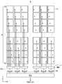
터치 센서들(TS1~TS4)은 도 4와 같이 표시패널(10)의 픽셀 어레이에 내장될 수 있다. 도 4를 참조하면, 표시패널(10)의 픽셀 어레이는 터치 센서들(TS1~TS4)과, 터치 센서들(TS1~TS4)과 연결된 센서 라인들(L1~Li, i는 m, n 보다 작은 양의 정수)을 포함한다. 픽셀들(101)의 공통전극(COM)은 다수의 세그먼트들(segment)로 분할된다. 터치 센서들(TS1~TS4)은 분할된 공통전극(COM)으로 구현된다. 하나의 공통전극 세그먼트(segment)는 다수의 픽셀들(101)에 공통으로 연결되고 하나의 터치 센서를 형성한다. 이 터치 센서들(TS1~TS4)은 디스플레이 구동 기간(Td1, Td2) 동안 픽셀들(101)에 공통전압(Vcom)을 공급하고, 터치 센서 구동 기간(Tt) 동안 터치 구동 신호(Vdrv)를 입력 받아 터치 센싱값을 센싱한다. 도 4는 자기 정전 용량 타입의 터치 센서를 도시하였으나, 터치 센서들(TS1~TS4)은 이에 한정되지 않는다.The touch sensors TS1 to TS4 may be embedded in the pixel array of the
터치 구동부(18)는 터치 전후 터치 센서(TS1~TS4)의 전하 변화량을 센싱하여 손가락(또는, 스타일러스 펜)과 같은 전도성 물질의 터치 여부와 그 위치를 판단한다. 터치 구동부(18)는 터치 센서(TS1~TS4)들로부터 수신되는 터치 센싱값들 중에서 기설정된 기준값보다 높은 터치 센싱값을 가지는 터치 포인트의 수를 카운팅하고, 카운팅된 터치 포인트의 수에 따라 터치 게인을 조정한다. 터치 구동부(18)는 터치 센싱값의 유무에 따라 달라지는 터치 센서(TS1~TS4)의 전하 변화량을 분석하여 터치 센싱값을 판단하고, 터치 입력 위치의 좌표를 계산한다. 터치 입력 위치의 좌표 정보(TDATA(XY))는 호스트 시스템(19)으로 전송된다.The
본 발명의 표시장치는 터치 입력을 센싱하는 기간과 입력 영상 데이터가 기입되는 기간을 시간적으로 분리한다. 이를 위해, 타이밍 컨트롤러(16)는 도 3과 같이 터치 인에이블 신호(TEN)을 기초로 하여, 1 프레임 기간을 터치 입력을 센싱하기 위한 터치 센서 구동 기간(Tt)과 입력 영상 데이터를 기입하기 위한 디스플레이 구동 기간(Td)으로 시분할할 수 있다. 도 5에서는 1 프레임 기간에 하나의 터치 센서 구동 기간(Tt)과 하나의 디스플레이 구동 기간(Td)으로 시분할하는 것을 도시하였으나, 이에 한정되는 것은 아니며, 1 프레임 기간에 적어도 하나 이상의 터치 센서 구동 기간(Tt)과, 적어도 하나 이상의 디스플레이 구동 기간(Td)으로 시분할될 수 있다.The display device of the present invention temporally separates the period of sensing the touch input and the period of input image data. To this end, the
디스플레이 구동 기간(Td) 동안, 데이터 구동부(12)는 타이밍 컨트롤러(16)의 제어 하에 데이터전압을 데이터라인들(D1~Dm)에 공급하고, 게이트 구동부(14)는 타이밍 컨트롤러(16)의 제어 하에 데이터전압에 동기되는 게이트펄스를 게이트라인들(G1~Gn)에 순차적으로 공급한다. 한편, 디스플레이 구동 기간(Td) 동안, 터치 구동부(18)는 터치 센싱 동작을 중지한다.During the display driving period Td, the
터치 센서 구동 기간(Tt) 동안, 터치 구동부(18)는 터치 센서들(TS1~TS4)을 구동한다. 터치 구동부(18)는 터치 구동 신호(Vdrv)를 센서라인들(L1~Li)을 통해 터치 센서들(TS1~TS4)에 공급하여 터치 센싱값을 센싱한다.During the touch sensor driving period Tt, the
한편, 터치 센서 구동 기간(Tt) 동안, 디스플레이 구동부(12, 14)는 픽셀들(101)에 연결된 신호라인들(D1~Dm, G1~Gn)에 터치 구동 신호(Vdrv)에 동기되는 제1 및 제2 교류 신호(LFD1, LFD2)를 공급함으로써, 픽셀들(101)에 연결된 신호라인들(D1~Dm, G1~Gn)과 터치 센서들(TS1~TS4) 사이의 기생 용량을 최소화한다.During the touch sensor driving period Tt, the
터치 센서 구동부(RIC)는 도 5와 같이, 터치 센서 구동 기간(Tt) 동안 터치 구동 신호(Vdrv)를 터치 센서들(TS1~TS4)에 공급한다. 그리고, 디스플레이 구동부(12, 14)는 도 5와 같이 터치 센서 구동 기간(Tt) 동안 제1 교류 신호(LFD1)를 데이터라인들(D1~Dm)에 공급함과 아울러, 제2 교류 신호(LFD2)를 게이트라인들(G1~Gn)에 공급한다. 즉, 터치 센서 구동부(RIC)는 터치 센싱값을 센싱하기 위한 터치 센서 구동 기간(Tt) 동안, 터치 센서들(TS1~TS4)에는 터치 구동 신호(Vdrv)를 공급하고, 픽셀(101)들에 연결된 데이터라인들(D1~Dm)에는 터치 구동 신호(Vdrv)와 동일한 위상 및 진폭을 갖는 제1 교류신호(LFD1)가 공급되고, 픽셀(101)들에 연결된 게이트라인들(G1~Gn)에는 터치 구동 신호(Vdrv)와 동일한 위상 및 진폭을 갖는 제2 교류신호(LFD2)가 공급된다.The touch sensor driving unit RIC supplies the touch driving signals Vdrv to the touch sensors TS1 to TS4 during the touch sensor driving period Tt as shown in FIG. The
터치 센서 구동부(RIC)는 도 6에 도시된 바와 같이, 멀티플렉서(MUX)와 센싱 유닛(SU)을 포함할 수 있다. 멀티플렉서(MUX)는 MCU(Micro Controller Unit)의 제어 하에 센싱부(SU)에 의해 액세스되는 터치 센서(TS)들을 선택한 후, 선택된 터치 센서(TS)들에 터치 구동 신호(Vdrv)를 공급한다.The touch sensor driver RIC may include a multiplexer MUX and a sensing unit SU, as shown in FIG. The multiplexer MUX selects the touch sensors TS to be accessed by the sensing unit SU under the control of an MCU (Micro Controller Unit), and then supplies the touch driving signals Vdrv to the selected touch sensors TS.
센싱 유닛(SU)은 멀티플렉서(MUX)를 통해 센서라인들(L1~Li)에 연결되어 터치 센서(TS)들로부터 수신되는 전압 파형의 변화를 측정하여 디지털 데이터로 변환한다. 센싱 유닛(SU)은 수신된 터치 센서(TS)들의 전압을 증폭하는 증폭기, 증폭기의 전압을 누적하는 적분기, 적분기의 전압을 디지털 데이터로 변환하는 아날로그 디지털 변환기(Analog-to-Digital Converter, 이하 "ADC"라 함)를 포함한다. ADC로부터 출력된 디지털 데이터는 터치 원시 데이터(Touch raw data)로서 MCU(Micro Controller Unit)로 전송된다.The sensing unit SU is connected to the sensor lines L1 to Li through a multiplexer MUX to measure a change in the voltage waveform received from the touch sensors TS and convert the measurement result into digital data. The sensing unit SU includes an amplifier for amplifying the voltage of the received touch sensors TS, an integrator for accumulating the voltage of the amplifier, an analog-to-digital converter (hereinafter referred to as " ADC "). The digital data output from the ADC is transferred to the MCU (Micro Controller Unit) as touch raw data.
도 7은 본 발명의 실시 예에 따른 터치 구동부의 구성을 보여준다.FIG. 7 shows a configuration of a touch driver according to an embodiment of the present invention.
도 7을 살펴보면, 본 발명의 실시 예에 따른 터치 구동부는 터치 센서들로부터 수신되는 터치 센서 센싱값들 중에서 기설정된 기준값보다 높은 터치 센싱값을 가지는 터치 포인트의 수를 카운팅하고, 카운팅된 터치 포인트의 수에 따라 터치 게인을 저정한다. 터치 구동부는 싱글 터치 또는 멀티 터치에 따라 터치 게인을 다르게 조정할 수 있다.7, the touch driver according to the embodiment of the present invention counts the number of touch points having a touch sensing value higher than a predetermined reference value among the touch sensor sensing values received from the touch sensors, Set the touch gain according to the number. The touch driver may adjust the touch gain differently according to the single-touch or multi-touch.
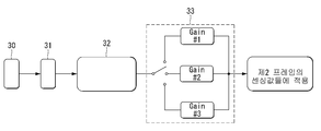
터치 구동부는 센싱 유닛(30), 비교부(31), 카운터부(32) 및 게인조정부(33)를 포함한다.The touch driver includes a
센싱 유닛(30)에 대한 설명은 앞에서 충분히 설명하였으므로, 여기서는 생략하기로 한다.Since the description of the
비교부(31)는 터치 센싱값들을 기설정된 기준값과 비교한다. 기설정된 기준값은 주변 환경 등에 의해 재설정될 수 있다. 비교부(31)는 입력되는 터치 센싱값들이 기설정된 기준값보다 높으면, 이에 대한 데이터를 카운터부(32)에 출력한다. 비교부(31)는 입력되는 터치 센싱값들이 기설정된 기준값보다 낮으면, 터치가 입력되지 않았거나 터치 잡음이라고 판단할 수 있다.The comparing
카운터부(32)는 비교부(31)를 통해 터치 센싱값들이 기준값보다 높은 터치 센싱 값을 가지면 터치 포인트의 수를 카운팅한다. 카운터부(32)는 기준값보다 높은 터치 센싱값을 입력받아 터치 포인트의 수를 카운팅한 카운트를 룩업 테이블 또는 메모리에 저장할 수 있다. 카운터부(32)는 하나의 프레임이 끝날 때마다 초기화된다. 카운터부(32)는 프레임이 시작되기 전에 초기화되고, 초기화된 상태에서 터치 포인트의 수를 카운팅한다. 이와 같이, 매프레임마다 초기화함으로써, 보다 정확한 터치 포인트의 수를 카운팅할 수 있다.The
게인조정부(33)는 터치 포인트의 수에 따라 터치 게인을 조정한다. 게인조정부(33)는 터치 포인트의 수에 따른 터치 게인을 룩업 테이블 또는 메모리에 저장할 수 있다. 룩업 테이블 또는 메모리에 저장된 터치 게인들은 터치 포인트의 수에 따라 조정되어 터치 센싱값들에 적용될 수 있다. 게인조정부(33)는 터치 포인트의 수에 따라 터치 게인을 선택할 수 있는 선택부를 포함할 수 있다. 선택부는 터치 포인트의 수가 “3”인 경우에는 이에 대응되는 터치 게인 #3이 선택되도록 스위칭 동작하고, 터치 포인트의 수가 “2”인 경우에는 이에 대응되는 터치 게인 #2가 선택되도록 스위칭 동작하고, 터치 포인트의 수가 “1”인 경우에는 이에 대응되는 터치 게인 #1이 선택되도록 스위칭 동작된다. 터치 게인 #1 내지 터치 게인 #3은 서로 다른 게인 값을 가진다.The
또한, 터치 구동부는 터치 센싱값들을 메모리에 저장한다. 터치 구동부는 터치 포인트의 수에 따라 터치 게인을 조정한 후 조정된 터치 게인을 메모리로부터 읽어낸 터치 센싱값들에 적용할 수 있다. 여기서 메모리는 터치 센싱값들만 저장하는 것이 아니며, 터치 게인, 터치 포인트의 수를 카운트한 값 등을 저장할 수 있다.Also, the touch driver stores the touch sensing values in a memory. The touch driver may adjust the touch gain according to the number of touch points and then apply the adjusted touch gain to the touch sensing values read from the memory. Here, the memory does not store only the touch sensing values, but can store the touch gain, the value obtained by counting the number of touch points, and the like.
상술한 바와 같이, 본 발명의 터치 구동부는 터치 포인트의 수에 따라 터치 게인을 조정함으로써, 싱글 터치 또는 멀티 터치에 상관없이 터치 감도가 저하되는 것을 방지할 수 있다.As described above, the touch driver of the present invention can prevent the touch sensitivity from being lowered regardless of the single-touch or multi-touch by adjusting the touch gain according to the number of touch points.
도 8은 도 7의 터치 구동부의 구동동작을 순서대로 보여주고, 도 9는 본 발명에 따라 프레임별로 조정된 터치 게인이 적용된 것을 보여주고, 도 10은 본 발명에 따른 싱글 터치일 때의 터치 센싱값과 멀티 터치일 때의 터치 센싱값을 보여준다.FIG. 8 shows the driving operation of the touch driver of FIG. 7 in order, FIG. 9 shows application of the touch gain adjusted for each frame according to the present invention, FIG. 10 shows the touch sensing Value and multi-touch touch sensing value.
도 8을 살펴보면, 본 발명의 터치 구동부는 터치 센서들로부터 터치 센싱값들을 수신한다.Referring to FIG. 8, the touch driver of the present invention receives touch sensing values from touch sensors.
터치 센서들로부터 수신된 터치 센싱값들은 기설정된 기준값과 비교한다. 터치 센싱값들 중 기준값보다 높은 터치 센싱값을 가지는 터치 포인트의 수가 카운팅된다(S110).The touch sensing values received from the touch sensors are compared with preset reference values. The number of touch points having a touch sensing value higher than a reference value among the touch sensing values is counted (S110).
터치 포인트의 수를 카운팅은 하나의 프레임이 끝나고 다음 프레임이 시작되기 전까지 계속해서 카운팅될 수 있다(S120). 하나의 프레임이 끝나면, 카운팅된 터치 포인트의 수는 초기화될 수 있다.The counting of the number of touch points can be continuously counted until one frame ends and the next frame starts (S120). When one frame ends, the number of counted touch points can be initialized.
하나의 프레임이 종료된 후 터치 센싱값들 중 기준값보다 높은 터치 센싱값을 가지는 터치 포인트의 수의 최종 카운트 값을 체크하고, 최종 카운트 값에 따라 터치 게인을 조정할 수 있다. 터치 게인은 상향 조정되거나 하향 조정될 수 있다(S130,S140).The final count value of the number of touch points having a touch sensing value higher than the reference value among the touch sensing values after one frame ends can be checked and the touch gain can be adjusted according to the final count value. The touch gain can be adjusted upward or downward (S130, S140).
터치 구동부는 제1 프레임에서 터치 포인트의 수에 따라 터치 게인을 조정하고, 조정된 터치 게인을 제1 프레임에 이은 제2 프레임의 터치 센싱값들에 적용할 수 있다(S150a,S150b,S150c). 도 9를 참고하면, 제1 프레임에서 카운트된 터치 포인트의 수가 3개일 경우, 터치 게인을 2에서 3으로 상향 조정하고, 조정된 터치 게인을 제2 프레임의 터치 센싱값에 적용할 수 있다. 제2 프레임은 터치 게인이 조정되어 3이 될 수 있다.The touch driver may adjust the touch gain according to the number of touch points in the first frame and apply the adjusted touch gain to the touch sensing values of the second frame following the first frame (S150a, S150b, S150c). Referring to FIG. 9, when the number of touch points counted in the first frame is three, the touch gain can be adjusted upward from 2 to 3, and the adjusted touch gain can be applied to the second frame's touch sensing value. And the second frame can be set to 3 by adjusting the touch gain.
또한, 제2 프레임에서 카운트된 터치 포인트의 수가 1개일 경우, 터치 게인을 3에서 1로 하향 조정하고, 조정된 터치 게인을 제3 프레임의 터치 센싱값에 적용할 수 있다. 제3 프레임은 터치 게인이 조정되어 1이 될 수 있다.When the number of touch points counted in the second frame is 1, the touch gain can be adjusted down from 3 to 1, and the adjusted touch gain can be applied to the touch sensing value of the third frame. The third frame can be set to 1 by adjusting the touch gain.
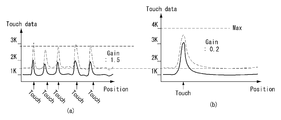
도 10의 (a)는 멀티 터치일 때를 보여주고, 도 10의 (b)는 싱글 터치일 때를 보여준다. 멀티 터치일 때는 터치 포인트의 수가 많기 때문에 터치 게인을 상향 조정하고, 싱글 터치일 때는 포인트의 수가 적기 때문에 터치 게인을 하향 조정할 수 있다. 이와 같이, 본 발명의 터치 구동부는 터치 포인트의 수에 따라 터치 게인을 용이하게 조정할 수 있다. 이에 따라, 멀티 터치 조건에서도 싱글 터치 수준의 터치 감도를 용이하게 확보할 수 있다.10 (a) shows a case of multi-touch, and Fig. 10 (b) shows a case of a single touch. In case of multi-touch, the touch gain is adjusted upward because the number of touch points is large. In case of a single touch, the touch gain can be adjusted downward because the number of points is small. As described above, the touch driver of the present invention can easily adjust the touch gain according to the number of touch points. Accordingly, even in a multi-touch condition, the touch sensitivity of a single touch level can be easily secured.
이상 설명한 내용을 통해 당업자라면 본 발명의 기술사상을 일탈하지 아니하는 범위에서 다양한 변경 및 수정이 가능함을 알 수 있을 것이다. 따라서, 본 발명의 기술적 범위는 명세서의 상세한 설명에 기재된 내용으로 한정되는 것이 아니라 특허 청구의 범위에 의해 정하여져야만 할 것이다.It will be apparent to those skilled in the art that various modifications and variations can be made in the present invention without departing from the spirit or scope of the invention. Therefore, the technical scope of the present invention should not be limited to the contents described in the detailed description of the specification, but should be defined by the claims.
10 : 표시패널
12 : 데이터 구동회로
14 : 게이트 구동회로
16 : 타이밍 컨트롤러
18 : 터치 구동부
19 : 호스트 시스템
30 : ADC
31 : 비교부
32 : 카운터부
33 : 게인조정부10: display panel 12: data driving circuit
14: Gate driving circuit 16: Timing controller
18: touch driver 19: host system
30: ADC 31:
32: Counter section 33: Gain adjustment section
Claims (5)
상기 터치 센서들로부터 수신되는 터치 센싱값들 중에서 기설정된 기준값보다 높은 터치 센싱값을 가지는 터치 포인트의 수를 카운팅하고, 카운팅된 상기 터치 포인트의 수에 따라 터치 게인을 조정하는 터치 구동부;를 포함하는 터치 센서 내장형 표시장치.A display panel including a plurality of touch sensors embedded in the pixel array,
And a touch driver for counting the number of touch points having a touch sensing value higher than a predetermined reference value among the touch sensing values received from the touch sensors and adjusting the touch gain according to the number of the counted touch points, Display device with integrated touch sensor.
상기 터치 구동부는 제1 프레임에서 상기 터치 포인트의 수에 따라 상기 터치 게인을 조정하고, 조정된 상기 터치 게인을 상기 제1 프레임에 이은 제2 프레임의 상기 터치 센싱값들에 적용하는 터치 센싱 내장형 표시장치.The method according to claim 1,
Wherein the touch driver adjusts the touch gain in accordance with the number of touch points in a first frame and applies the adjusted touch gain to the touch sensing values of a second frame subsequent to the first frame, Device.
상기 터치 구동부는 상기 터치 센싱값들을 메모리에 저장하고,
상기 터치 포인트의 수에 따라 상기 터치 게인을 조정한 후 조정된 상기 터치 게인을 상기 메모리로부터 읽어낸 상기 터치 센싱값들에 적용하는 터치 센싱 내장형 표시장치.The method according to claim 1,
Wherein the touch driver stores the touch sensing values in a memory,
And adjusting the touch gain according to the number of touch points and applying the adjusted touch gain to the touch sensing values read from the memory.
상기 터치 구동부는
상기 터치 센서들로부터 수신되는 상기 터치 센싱값을 센싱하는 센싱유닛과,
상기 터치 센싱값들을 기설정된 기준값과 비교하는 비교부와,
상기 비교부를 통해 상기 터치 센싱값들 중 상기 기준값보다 높은 센싱 값을 가지는 상기 터치 포인트의 수를 카운팅하는 카운터부와,
상기 터치 포인트의 수에 따라 상기 터치 게인을 조정하는 게인조정부를 포함하는 터치 센싱 내장형 표시장치.The method according to claim 1,
The touch driver
A sensing unit for sensing the touch sensing value received from the touch sensors;
A comparator for comparing the touch sensing values with a predetermined reference value,
A counter for counting the number of touch points having a sensing value higher than the reference value among the touch sensing values through the comparator;
And a gain adjuster for adjusting the touch gain according to the number of touch points.
상기 카운터부는 하나의 프레임이 끝날 때마다 초기화되는 터치 센싱 내장형 표시장치.The method of claim 3,
Wherein the counter unit is initialized at the end of one frame.
Priority Applications (1)
| Application Number | Priority Date | Filing Date | Title |
|---|---|---|---|
| KR1020150191825A KR102513384B1 (en) | 2015-12-31 | 2015-12-31 | A touch sensor integrated type display device |
Applications Claiming Priority (1)
| Application Number | Priority Date | Filing Date | Title |
|---|---|---|---|
| KR1020150191825A KR102513384B1 (en) | 2015-12-31 | 2015-12-31 | A touch sensor integrated type display device |
Publications (2)
| Publication Number | Publication Date |
|---|---|
| KR20170080351A true KR20170080351A (en) | 2017-07-10 |
| KR102513384B1 KR102513384B1 (en) | 2023-03-22 |
Family
ID=59356364
Family Applications (1)
| Application Number | Title | Priority Date | Filing Date |
|---|---|---|---|
| KR1020150191825A KR102513384B1 (en) | 2015-12-31 | 2015-12-31 | A touch sensor integrated type display device |
Country Status (1)
| Country | Link |
|---|---|
| KR (1) | KR102513384B1 (en) |
Citations (3)
| Publication number | Priority date | Publication date | Assignee | Title |
|---|---|---|---|---|
| KR20080032901A (en) * | 2006-10-11 | 2008-04-16 | 삼성전자주식회사 | Apparatus and method for multi-touch decision |
| JP2013222283A (en) * | 2012-04-16 | 2013-10-28 | Sharp Corp | Electronic device, and method and program for controlling the same |
| KR20150105689A (en) * | 2014-03-10 | 2015-09-18 | 삼성전기주식회사 | Touch separation method and touchscreen apparatus |
-
2015
- 2015-12-31 KR KR1020150191825A patent/KR102513384B1/en active IP Right Grant
Patent Citations (3)
| Publication number | Priority date | Publication date | Assignee | Title |
|---|---|---|---|---|
| KR20080032901A (en) * | 2006-10-11 | 2008-04-16 | 삼성전자주식회사 | Apparatus and method for multi-touch decision |
| JP2013222283A (en) * | 2012-04-16 | 2013-10-28 | Sharp Corp | Electronic device, and method and program for controlling the same |
| KR20150105689A (en) * | 2014-03-10 | 2015-09-18 | 삼성전기주식회사 | Touch separation method and touchscreen apparatus |
Also Published As
| Publication number | Publication date |
|---|---|
| KR102513384B1 (en) | 2023-03-22 |
Similar Documents
| Publication | Publication Date | Title |
|---|---|---|
| US10203782B2 (en) | Stylus pen and touch sensing system and driving method of the same | |
| KR102342357B1 (en) | Display device and driving method of the same | |
| US10338711B2 (en) | Display device, method of driving the same, and driving circuit thereof | |
| KR101981529B1 (en) | Touch sensing apparatus and driving method thereofp | |
| US9857914B2 (en) | Touch sensing system | |
| US10268285B2 (en) | Stylus pen, touch sensing system and driving method thereof | |
| US20150185914A1 (en) | Touch sensing system | |
| US10324567B2 (en) | Touch sensing system and method of reducing latency thereof | |
| US9164637B2 (en) | Touch sensing device | |
| KR20180077375A (en) | Touch sensing system and driving method of the same | |
| KR101885815B1 (en) | Touch sensing apparatus and display device using the same | |
| KR101731174B1 (en) | Touch sensor integrated type display device | |
| KR20170081068A (en) | Touch sensor integrated type display device | |
| KR20170027243A (en) | Active stylus pen and touch sensing system and driving method of the same | |
| KR102440812B1 (en) | Touch sensing apparatus and driving method thereof | |
| KR102390170B1 (en) | Display device and driving method thereof | |
| KR20170036940A (en) | Active touch pen and touch sensing system and driving method of the same | |
| KR101667078B1 (en) | Touch sensing device, system and enhancement method of touch report rate thereof | |
| KR20150139013A (en) | Sensing system | |
| KR102063347B1 (en) | Touch sensing system and method of controlling smoothing filter thereof | |
| KR102513384B1 (en) | A touch sensor integrated type display device | |
| KR20160082875A (en) | Touch sensor intergrated type display device | |
| KR102520692B1 (en) | Touch sensing system | |
| US9733778B2 (en) | Touch sensing apparatus | |
| KR20170015648A (en) | Stylus pen and touch sensing system and driving method of the same |
Legal Events
| Date | Code | Title | Description |
|---|---|---|---|
| A201 | Request for examination | ||
| E902 | Notification of reason for refusal | ||
| E701 | Decision to grant or registration of patent right | ||
| GRNT | Written decision to grant |