KR20170076690A - Instruments for minimally invasive surgical procedures - Google Patents
Instruments for minimally invasive surgical procedures Download PDFInfo
- Publication number
- KR20170076690A KR20170076690A KR1020177011813A KR20177011813A KR20170076690A KR 20170076690 A KR20170076690 A KR 20170076690A KR 1020177011813 A KR1020177011813 A KR 1020177011813A KR 20177011813 A KR20177011813 A KR 20177011813A KR 20170076690 A KR20170076690 A KR 20170076690A
- Authority
- KR
- South Korea
- Prior art keywords
- surgical
- distal end
- tube
- laser
- coupled
- Prior art date
Links
Images


Classifications
-
- A—HUMAN NECESSITIES
- A61—MEDICAL OR VETERINARY SCIENCE; HYGIENE
- A61B—DIAGNOSIS; SURGERY; IDENTIFICATION
- A61B1/00—Instruments for performing medical examinations of the interior of cavities or tubes of the body by visual or photographical inspection, e.g. endoscopes; Illuminating arrangements therefor
- A61B1/00064—Constructional details of the endoscope body
- A61B1/00071—Insertion part of the endoscope body
- A61B1/0008—Insertion part of the endoscope body characterised by distal tip features
- A61B1/00082—Balloons
-
- A—HUMAN NECESSITIES
- A61—MEDICAL OR VETERINARY SCIENCE; HYGIENE
- A61B—DIAGNOSIS; SURGERY; IDENTIFICATION
- A61B1/00—Instruments for performing medical examinations of the interior of cavities or tubes of the body by visual or photographical inspection, e.g. endoscopes; Illuminating arrangements therefor
- A61B1/00064—Constructional details of the endoscope body
- A61B1/00071—Insertion part of the endoscope body
- A61B1/0008—Insertion part of the endoscope body characterised by distal tip features
- A61B1/00087—Tools
-
- A—HUMAN NECESSITIES
- A61—MEDICAL OR VETERINARY SCIENCE; HYGIENE
- A61B—DIAGNOSIS; SURGERY; IDENTIFICATION
- A61B1/00—Instruments for performing medical examinations of the interior of cavities or tubes of the body by visual or photographical inspection, e.g. endoscopes; Illuminating arrangements therefor
- A61B1/00131—Accessories for endoscopes
- A61B1/00135—Oversleeves mounted on the endoscope prior to insertion
-
- A—HUMAN NECESSITIES
- A61—MEDICAL OR VETERINARY SCIENCE; HYGIENE
- A61B—DIAGNOSIS; SURGERY; IDENTIFICATION
- A61B1/00—Instruments for performing medical examinations of the interior of cavities or tubes of the body by visual or photographical inspection, e.g. endoscopes; Illuminating arrangements therefor
- A61B1/00147—Holding or positioning arrangements
- A61B1/00154—Holding or positioning arrangements using guiding arrangements for insertion
-
- A—HUMAN NECESSITIES
- A61—MEDICAL OR VETERINARY SCIENCE; HYGIENE
- A61B—DIAGNOSIS; SURGERY; IDENTIFICATION
- A61B1/00—Instruments for performing medical examinations of the interior of cavities or tubes of the body by visual or photographical inspection, e.g. endoscopes; Illuminating arrangements therefor
- A61B1/005—Flexible endoscopes
- A61B1/0051—Flexible endoscopes with controlled bending of insertion part
- A61B1/0055—Constructional details of insertion parts, e.g. vertebral elements
-
- A—HUMAN NECESSITIES
- A61—MEDICAL OR VETERINARY SCIENCE; HYGIENE
- A61B—DIAGNOSIS; SURGERY; IDENTIFICATION
- A61B1/00—Instruments for performing medical examinations of the interior of cavities or tubes of the body by visual or photographical inspection, e.g. endoscopes; Illuminating arrangements therefor
- A61B1/005—Flexible endoscopes
- A61B1/0051—Flexible endoscopes with controlled bending of insertion part
- A61B1/0057—Constructional details of force transmission elements, e.g. control wires
-
- A—HUMAN NECESSITIES
- A61—MEDICAL OR VETERINARY SCIENCE; HYGIENE
- A61B—DIAGNOSIS; SURGERY; IDENTIFICATION
- A61B1/00—Instruments for performing medical examinations of the interior of cavities or tubes of the body by visual or photographical inspection, e.g. endoscopes; Illuminating arrangements therefor
- A61B1/012—Instruments for performing medical examinations of the interior of cavities or tubes of the body by visual or photographical inspection, e.g. endoscopes; Illuminating arrangements therefor characterised by internal passages or accessories therefor
- A61B1/018—Instruments for performing medical examinations of the interior of cavities or tubes of the body by visual or photographical inspection, e.g. endoscopes; Illuminating arrangements therefor characterised by internal passages or accessories therefor for receiving instruments
-
- A—HUMAN NECESSITIES
- A61—MEDICAL OR VETERINARY SCIENCE; HYGIENE
- A61B—DIAGNOSIS; SURGERY; IDENTIFICATION
- A61B1/00—Instruments for performing medical examinations of the interior of cavities or tubes of the body by visual or photographical inspection, e.g. endoscopes; Illuminating arrangements therefor
- A61B1/06—Instruments for performing medical examinations of the interior of cavities or tubes of the body by visual or photographical inspection, e.g. endoscopes; Illuminating arrangements therefor with illuminating arrangements
-
- A—HUMAN NECESSITIES
- A61—MEDICAL OR VETERINARY SCIENCE; HYGIENE
- A61B—DIAGNOSIS; SURGERY; IDENTIFICATION
- A61B18/00—Surgical instruments, devices or methods for transferring non-mechanical forms of energy to or from the body
- A61B18/18—Surgical instruments, devices or methods for transferring non-mechanical forms of energy to or from the body by applying electromagnetic radiation, e.g. microwaves
- A61B18/20—Surgical instruments, devices or methods for transferring non-mechanical forms of energy to or from the body by applying electromagnetic radiation, e.g. microwaves using laser
- A61B18/22—Surgical instruments, devices or methods for transferring non-mechanical forms of energy to or from the body by applying electromagnetic radiation, e.g. microwaves using laser the beam being directed along or through a flexible conduit, e.g. an optical fibre; Couplings or hand-pieces therefor
- A61B18/24—Surgical instruments, devices or methods for transferring non-mechanical forms of energy to or from the body by applying electromagnetic radiation, e.g. microwaves using laser the beam being directed along or through a flexible conduit, e.g. an optical fibre; Couplings or hand-pieces therefor with a catheter
-
- A—HUMAN NECESSITIES
- A61—MEDICAL OR VETERINARY SCIENCE; HYGIENE
- A61M—DEVICES FOR INTRODUCING MEDIA INTO, OR ONTO, THE BODY; DEVICES FOR TRANSDUCING BODY MEDIA OR FOR TAKING MEDIA FROM THE BODY; DEVICES FOR PRODUCING OR ENDING SLEEP OR STUPOR
- A61M25/00—Catheters; Hollow probes
- A61M25/01—Introducing, guiding, advancing, emplacing or holding catheters
-
- A—HUMAN NECESSITIES
- A61—MEDICAL OR VETERINARY SCIENCE; HYGIENE
- A61B—DIAGNOSIS; SURGERY; IDENTIFICATION
- A61B1/00—Instruments for performing medical examinations of the interior of cavities or tubes of the body by visual or photographical inspection, e.g. endoscopes; Illuminating arrangements therefor
- A61B1/04—Instruments for performing medical examinations of the interior of cavities or tubes of the body by visual or photographical inspection, e.g. endoscopes; Illuminating arrangements therefor combined with photographic or television appliances
-
- A—HUMAN NECESSITIES
- A61—MEDICAL OR VETERINARY SCIENCE; HYGIENE
- A61B—DIAGNOSIS; SURGERY; IDENTIFICATION
- A61B1/00—Instruments for performing medical examinations of the interior of cavities or tubes of the body by visual or photographical inspection, e.g. endoscopes; Illuminating arrangements therefor
- A61B1/06—Instruments for performing medical examinations of the interior of cavities or tubes of the body by visual or photographical inspection, e.g. endoscopes; Illuminating arrangements therefor with illuminating arrangements
- A61B1/0661—Endoscope light sources
- A61B1/0676—Endoscope light sources at distal tip of an endoscope
-
- A—HUMAN NECESSITIES
- A61—MEDICAL OR VETERINARY SCIENCE; HYGIENE
- A61B—DIAGNOSIS; SURGERY; IDENTIFICATION
- A61B1/00—Instruments for performing medical examinations of the interior of cavities or tubes of the body by visual or photographical inspection, e.g. endoscopes; Illuminating arrangements therefor
- A61B1/12—Instruments for performing medical examinations of the interior of cavities or tubes of the body by visual or photographical inspection, e.g. endoscopes; Illuminating arrangements therefor with cooling or rinsing arrangements
- A61B1/126—Instruments for performing medical examinations of the interior of cavities or tubes of the body by visual or photographical inspection, e.g. endoscopes; Illuminating arrangements therefor with cooling or rinsing arrangements provided with means for cleaning in-use
-
- A—HUMAN NECESSITIES
- A61—MEDICAL OR VETERINARY SCIENCE; HYGIENE
- A61B—DIAGNOSIS; SURGERY; IDENTIFICATION
- A61B17/00—Surgical instruments, devices or methods, e.g. tourniquets
- A61B17/00234—Surgical instruments, devices or methods, e.g. tourniquets for minimally invasive surgery
- A61B2017/00292—Surgical instruments, devices or methods, e.g. tourniquets for minimally invasive surgery mounted on or guided by flexible, e.g. catheter-like, means
- A61B2017/003—Steerable
- A61B2017/00318—Steering mechanisms
- A61B2017/00331—Steering mechanisms with preformed bends
-
- A—HUMAN NECESSITIES
- A61—MEDICAL OR VETERINARY SCIENCE; HYGIENE
- A61B—DIAGNOSIS; SURGERY; IDENTIFICATION
- A61B18/00—Surgical instruments, devices or methods for transferring non-mechanical forms of energy to or from the body
- A61B2018/00005—Cooling or heating of the probe or tissue immediately surrounding the probe
- A61B2018/00011—Cooling or heating of the probe or tissue immediately surrounding the probe with fluids
- A61B2018/00029—Cooling or heating of the probe or tissue immediately surrounding the probe with fluids open
-
- A—HUMAN NECESSITIES
- A61—MEDICAL OR VETERINARY SCIENCE; HYGIENE
- A61B—DIAGNOSIS; SURGERY; IDENTIFICATION
- A61B18/00—Surgical instruments, devices or methods for transferring non-mechanical forms of energy to or from the body
- A61B2018/00315—Surgical instruments, devices or methods for transferring non-mechanical forms of energy to or from the body for treatment of particular body parts
- A61B2018/00339—Spine, e.g. intervertebral disc
-
- A—HUMAN NECESSITIES
- A61—MEDICAL OR VETERINARY SCIENCE; HYGIENE
- A61B—DIAGNOSIS; SURGERY; IDENTIFICATION
- A61B18/00—Surgical instruments, devices or methods for transferring non-mechanical forms of energy to or from the body
- A61B2018/00571—Surgical instruments, devices or methods for transferring non-mechanical forms of energy to or from the body for achieving a particular surgical effect
- A61B2018/00577—Ablation
-
- A—HUMAN NECESSITIES
- A61—MEDICAL OR VETERINARY SCIENCE; HYGIENE
- A61B—DIAGNOSIS; SURGERY; IDENTIFICATION
- A61B18/00—Surgical instruments, devices or methods for transferring non-mechanical forms of energy to or from the body
- A61B2018/00982—Surgical instruments, devices or methods for transferring non-mechanical forms of energy to or from the body combined with or comprising means for visual or photographic inspections inside the body, e.g. endoscopes
-
- A—HUMAN NECESSITIES
- A61—MEDICAL OR VETERINARY SCIENCE; HYGIENE
- A61B—DIAGNOSIS; SURGERY; IDENTIFICATION
- A61B2218/00—Details of surgical instruments, devices or methods for transferring non-mechanical forms of energy to or from the body
- A61B2218/001—Details of surgical instruments, devices or methods for transferring non-mechanical forms of energy to or from the body having means for irrigation and/or aspiration of substances to and/or from the surgical site
- A61B2218/002—Irrigation
-
- A—HUMAN NECESSITIES
- A61—MEDICAL OR VETERINARY SCIENCE; HYGIENE
- A61M—DEVICES FOR INTRODUCING MEDIA INTO, OR ONTO, THE BODY; DEVICES FOR TRANSDUCING BODY MEDIA OR FOR TAKING MEDIA FROM THE BODY; DEVICES FOR PRODUCING OR ENDING SLEEP OR STUPOR
- A61M25/00—Catheters; Hollow probes
- A61M25/01—Introducing, guiding, advancing, emplacing or holding catheters
- A61M25/0105—Steering means as part of the catheter or advancing means; Markers for positioning
- A61M25/0133—Tip steering devices
- A61M25/0147—Tip steering devices with movable mechanical means, e.g. pull wires
Landscapes
- Health & Medical Sciences (AREA)
- Life Sciences & Earth Sciences (AREA)
- Surgery (AREA)
- Animal Behavior & Ethology (AREA)
- Public Health (AREA)
- General Health & Medical Sciences (AREA)
- Veterinary Medicine (AREA)
- Engineering & Computer Science (AREA)
- Biomedical Technology (AREA)
- Heart & Thoracic Surgery (AREA)
- Biophysics (AREA)
- Physics & Mathematics (AREA)
- Nuclear Medicine, Radiotherapy & Molecular Imaging (AREA)
- Molecular Biology (AREA)
- Medical Informatics (AREA)
- Optics & Photonics (AREA)
- Pathology (AREA)
- Radiology & Medical Imaging (AREA)
- Pulmonology (AREA)
- Anesthesiology (AREA)
- Hematology (AREA)
- Electromagnetism (AREA)
- Otolaryngology (AREA)
- Endoscopes (AREA)
- Surgical Instruments (AREA)
- Laser Surgery Devices (AREA)
Abstract
본 발명에 따르면, 환자의 수술용 관의 한 모델을 제공하는 단계를 포함하되, 상기 수술용 관은 수술 시작 지점, 지지 조직 영역, 연성 조직 영역, 및 수술 표적을 포함하며, 수술용 관은 곡률을 가진다. 바디, 컨트롤 단부, 및 원위 단부를 가진 수술 도구를 포함하되, 상기 바디는 천골열공을 지나 환자의 척추관 내에 삽입하도록 형태가 형성되고 크기가 정해지며, 수술 도구의 바디 내에 복합 곡선을 포함하되, 상기 복합 곡선은 원위 단부의 원위 말단이 수술을 위해 척추관 내의 수술 표적에 위치될 때 척추관의 지지 조직 영역과 수술 도구 사이에 접촉 지점을 제공하도록 위치되어 원위 말단의 한 위치에 기계적 지지를 제공하는 제1 굽힘부를 포함하며, 복합 곡선은 원위 말단을 수술 표적을 향해 안내하도록 위치된 제2 굽힘부를 포함한다. According to the present invention, there is provided a method for providing a model of a surgical tube of a patient, the surgical tube including an operation start point, a support tissue region, a soft tissue region, and a surgical target, . A surgical instrument having a body, a control end, and a distal end, the body being shaped and sized for insertion into a vertebral body of a patient through a sacrum hole, wherein the body includes a composite curve in the body of the surgical tool, The composite curve is positioned to provide a point of contact between the support tissue region of the spinal canal and the surgical tool when the distal end of the distal end is located in the surgical target in the spinal canal for surgery, Wherein the composite curve comprises a second bend positioned to guide the distal end toward the surgical target.

Description
본 특허출원은 2014년 9월 30일에 출원된 미국 가특허출원번호 62/057,415호, 2014년 12월 5일에 출원된 미국 가특허출원번호 62/088,103호, 2014년 12월 5일에 출원된 미국 가특허출원번호 62/088,160호, 2015년 2월 6일에 출원된 미국 가특허출원번호 62/113,163호,2015년 2월 26일에 출원된 미국 가특허출원번호 62/121,108호, 및 2015년 9월 25일에 출원된 미국 가특허출원번호 62/232,654호를 기초로 우선권을 주장하고 있다. 상기 미국 특허출원들은 전반적으로 본 명세서에서 참조문헌들로 인용된다. This patent application is a continuation-in-part of U.S. Provisional Patent Application No. 62 / 057,415 filed on September 30, 2014, U.S. Patent Application No. 62 / 088,103 filed on December 5, 2014, filed December 5, 2014 U.S. Provisional Patent Application No. 62 / 088,160, filed February 6, 2015, U.S. Patent Application No. 62 / 113,163, filed February 6, 2015, U.S. Patent Application No. 62 / 121,108, filed February 26, 2015, Filed September 25, 2015, which is incorporated herein by reference in its entirety. These U.S. Patent Applications are incorporated herein by reference in their entirety.
본 발명은 미공군 계약번호 FA8721-05-C-0002에 따른다. 미정부가 본 발명의 특정 권리를 가진다. The present invention is subject to US Air Force Contract No. FA8721-05-C-0002. The US government has certain rights in this invention.
본 발명은 다양한 수술용 기구 및 최소 침습 수술 용도에 관한 것이다. The present invention relates to various surgical instruments and minimally invasive surgical applications.
최소 침습 수술에 대한 개선된 디바이스, 시스템, 및 방법에 관한 필요성이 존재한다. There is a need for an improved device, system, and method for minimally invasive surgery.
척추관(spinal canal)에서 황색인대(ligamentum flavum) 제거 수술 및 그 밖의 유사한 조직 제거 수술을 위해 다양한 도구 및 기술들이 제공된다. A variety of tools and techniques are provided for the removal of ligamentum flavum and other similar tissue removal operations in the spinal canal.
본 발명에 따른 방법은 환자의 수술용 관(surgical canal)의 한 모델(model)을 제공하는 단계를 포함할 수 있는데, 상기 수술용 관은 수술 시작 지점, 지지 조직 영역, 연성 조직 영역, 및 수술 표적을 포함하며, 수술용 관은 곡률을 가진다. 상기 방법은 복합 곡선(compound curve) 내에 원위 말단을 가진 수술 도구(surgical tool)를 형성하는 단계를 추가로 포함할 수 있는데, 상기 복합 곡선은 원위 말단이 수술을 위해 수술 표적(surgical target)에 위치될 때 수술용 관의 지지 조직 영역(supporting tissue region)과 수술 도구 사이에 접촉 지점을 제공하도록 위치되어 원위 말단의 한 위치에 기계적 지지(mechanical support)를 제공하는 제1 굽힘부(first bend)를 포함하며, 복합 곡선은 원위 말단을 수술 표적을 향해 안내하도록 위치된 제2 굽힘부(second bend)를 포함한다. The method according to the present invention may comprise the step of providing a model of a surgical canal of a patient, said surgical tube comprising a surgical site, a supportive tissue region, a soft tissue region, Target, and the surgical tube has curvature. The method may further comprise forming a surgical tool having a distal end in a compound curve wherein the distal end is positioned on a surgical target for surgery, A first bend positioned to provide a point of contact between the supporting tissue region of the surgical tube and the surgical instrument and providing a mechanical support at one location of the distal end, Wherein the composite curve includes a second bend positioned to guide the distal end toward the surgical target.
실시예들은 다음 특징들 중 하나 또는 그 이상의 특징을 가질 수 있다. 모델은 수술용 관의 2-차원 영상을 포함할 수 있다. 상기 2-차원 영상은 환자의 척추관의 횡단면(cross section)일 수 있다. 수술 도구는 내시경(endoscope) 및 내시경용 캐뉼라(cannula) 중 하나 이상을 포함할 수 있다. 상기 방법은 연성 조직 영역(soft tissue region)과 수술 도구 사이의 한 위치에 풍선(balloon)을 배치하는 단계, 풍선을 팽창시켜 연성 조직 영역과 수술 도구 사이에 연성 배리어(soft barrier)를 제공하는 단계, 수술 도구의 원위 말단을 조종하는 단계, 원위 말단이 수술 표적을 향하도록 조종하는 단계, 원위 말단이 연성 조직 영역으로부터 멀어지도록 조종하는 단계, 컨트롤 단부(control end)로부터 원위 말단으로 수술 도구를 통해 기계적으로 결합된 와이어(wire)를 사용하거나 또는 외부 자기장을 제공하여 수술 도구에 결합된 하나 또는 그 이상의 자석을 움직이도록 힘을 제공함으로써, 원위 말단을 조종하는 단계, 및/또는 상이한 곡률(curvature) 또는 강도(stiffness)를 가진 수술 도구 내에 하나 또는 그 이상의 동심적으로 배열된(concentrically nested) 튜브를 회전시키거나 또는 병진 운동시킴으로써(translating) 원위 말단을 조종하는 단계를 추가로 포함할 수 있다. Embodiments may have one or more of the following features. The model may include a two-dimensional image of the surgical tube. The two-dimensional image may be a cross section of the spinal canal of the patient. The surgical tool may include one or more of an endoscope and an endoscopic cannula. The method includes positioning a balloon at a location between a soft tissue region and a surgical tool, inflating the balloon to provide a soft barrier between the soft tissue region and the surgical tool, , Manipulating the distal end of the surgical instrument, manipulating the distal end to point to the surgical target, manipulating the distal end away from the soft tissue region, moving the control end from the control end to the distal end through the surgical tool Manipulating the distal end by providing mechanically coupled wires or by providing an external magnetic field to move one or more magnets coupled to the surgical tool, and / or providing a different curvature, Or concentric nested tube within a surgical tool having a stiffness, Or or by translation (translating) may further comprise the step of controlling the distal end.
한 양태에서, 디바이스(device)가 바디(body), 컨트롤 단부, 및 원위 단부를 가진 수술 도구를 포함하되, 상기 바디는 천골열공(sacral hiatus)을 지나 환자의 척추관 내에 삽입하도록 형태가 형성되고 크기가 정해지며, 컨트롤 단부는 사용을 위해 수술 도구가 배치될 때 환자의 외부에 위치되고, 원위 단부는 사용을 위해 수술 도구가 위치될 때 척추관 내에 위치된다. 디바이스는 수술 도구의 바디 내에 복합 곡선을 추가로 포함할 수 있는데, 상기 복합 곡선은 원위 단부의 원위 말단이 수술을 위해 척추관 내의 수술 표적에 위치될 때 척추관의 지지 조직 영역과 수술 도구 사이에 접촉 지점을 제공하도록 위치되어 원위 말단의 한 위치에 기계적 지지를 제공하는 제1 굽힘부를 포함하며, 복합 곡선은 원위 말단을 수술 표적을 향해 안내하도록 위치된 제2 굽힘부를 포함한다. In one aspect, a device includes a surgical tool having a body, a control end, and a distal end, the body being shaped to insert into a patient ' s spinal canal through a sacral hiatus, The control end is located outside the patient when the surgical tool is deployed for use and the distal end is located within the spinal canal when the surgical tool is positioned for use. The device may further include a composite curve in the body of the surgical tool, wherein the composite curve is a contact point between the support tissue region of the vertebral canal and the surgical tool when the distal end of the distal end is located in the surgical target in the spinal canal for surgery Wherein the composite curve includes a second bend positioned to guide the distal end toward the surgical target. ≪ RTI ID = 0.0 > [0002] < / RTI >
실시예들은 다음 특징들 중 하나 또는 그 이상의 특징을 가질 수 있다. 제1 굽힘부는, 원위 단부를 수술 표적에 대해 고정된 위치에 유지시키기 위하여, 제1 굽힘부의 제1 정점(first apex)과 제2 굽힘부의 제2 정점(second apex) 사이의 한 영역에서 척추관의 벽과 바디 사이에 적절한 짝 접촉(mating contact) 상태를 유지하기 위해 척추관의 원래 곡률로 변형되도록 선택된 사전결정된 강도(predetermined stiffness)를 가질 수 있다. 사전결정된 강도는 제2 정점이 척추관의 벽과 접촉되는 상태를 유지하게 할 수 있다. 제2 굽힘부는 사용을 위해 수술 도구가 배열될 때 원위 단부를 수술 표적을 향해 안내할 수 있다. 수술 도구는 내시경 및 내시경용 캐뉼라를 포함할 수 있다. 상기 디바이스는 원위 단부 가까이에서 바디에 결합된 자석, 컨트롤 단부와 원위 단부 사이에서 결합되어 바디에 대한 원위 단부의 한 위치를 조절하기 위한 컨트롤 와이어(control wire), 제2 굽힘부의 곡률을 조절하도록 작동가능한 바디 내의 하나 또는 그 이상의 동심적으로 배열되고 곡선의 튜브, 및 바디의 외부에 결합되고 척추관 내에서 바디를 움직이도록 팽창 가능한 하나 또는 그 이상의 풍선 중 하나 이상을 추가로 포함할 수 있다. 바디는 3 mm보다 크지 않은 외측 직경을 가질 수 있다. 디바이스는 수술 레이저(surgical laser)와 광에너지(optical energy)를 수술 레이저로부터 바디를 통해 원위 말단으로 전송하도록 위치된 광섬유, 및/또는 수술 표적의 무선주파수 제거(radio frequency ablation)를 위해 작동 가능하고 원위 단부에 결합된 전기수술식 무선주파수 디바이스를 추가로 포함할 수 있다. Embodiments may have one or more of the following features. The first bend is located in a region between the first apex of the first bend and the second apex of the second bend to maintain the distal end in a fixed position relative to the surgical target. And may have a predetermined stiffness selected to deform into the original curvature of the spinal canal to maintain a proper mating contact between the wall and the body. The predetermined strength may allow the second vertex to remain in contact with the wall of the spinal canal. The second bend can guide the distal end toward the surgical target when the surgical tool is arranged for use. The surgical tool may include an endoscope and an endoscope cannula. The device comprises a magnet coupled to the body near the distal end, a control wire coupled between the control end and the distal end to adjust one position of the distal end relative to the body, operative to adjust the curvature of the second bend, One or more concentricly arranged and curved tubes within a possible body, and one or more balloons coupled to the exterior of the body and inflatable to move the body within the spinal canal. The body may have an outside diameter not greater than 3 mm. The device is operable for radio frequency ablation of the surgical target and / or an optical fiber positioned to transmit a surgical laser and optical energy from the surgical laser to the distal end through the body, And may further include an electrosurgical radio frequency device coupled to the distal end.
또 다른 양태에서, 디바이스가 수술 동안 조작하기 위한 근위 단부, 수술 부위 내에 삽입하기 위한 원위 단부, 중공 코어(hollow core), 및 원위 단부에서 중공 코어로부터의 출구(exit)를 포함한다. 디바이스는, 또한, 상기 제1 튜브의 원위 단부에 결합된 복수의 플랩(flap), 제1 튜브 내에서 슬라이딩 가능하게 배열되고(slidably disposed) 제1 튜브에 대해 동심 배열된 제2 튜브, 및 컨트롤러를 포함할 수 있는데, 상기 컨트롤러는 복수의 플랩이 제1 튜브의 종축(longitudinal axis)에 대해 수직인 횡단면 내에 포함되는 전개되지 않은 상태(undeployed state)와 수술 부위를 둘러싸는 조직과 제1 튜브의 원위 단부 사이에서 기계적인 분리(mechanical separation)를 제공하기 위해 상기 횡단면 외부에 적어도 부분적으로 배열되는 전개된 상태(deployed state) 사이에서 제1 튜브에 대해 복수의 플랩을 움직이도록 작동될 수 있다. In another aspect, the device includes a proximal end for manipulation during surgery, a distal end for insertion into a surgical site, a hollow core, and an exit from the hollow core at the distal end. The device also includes a plurality of flaps coupled to a distal end of the first tube, a second tube slidably disposed within the first tube and concentrically arranged with respect to the first tube, The controller including an undeployed state in which a plurality of flaps are contained within a transverse plane perpendicular to the longitudinal axis of the first tube, a tissue surrounding the surgical site, And may be operable to move the plurality of flaps relative to the first tube between a deployed state at least partially arranged outside the cross-section to provide mechanical separation between the distal ends.
실시예들은 다음 특징들 중 하나 또는 그 이상의 특징을 가질 수 있다. 제2 튜브는 복수의 플랩들 중 하나에서 상응하는 요소와 각각 기계적으로 짝을 이루는 복수의 요소를 포함할 수 있으며, 제2 튜브가 제1 튜브에 대해 제1 방향으로 슬라이딩 되면 복수의 요소가 복수의 플랩과 결합하게 되고 각각의 복수의 플랩이 전개되지 않은 상태로부터 전개된 상태로 움직이게 된다. 제2 튜브가 제1 방향과 반대 방향인 제2 방향으로 슬라이딩 되면 복수의 요소가 복수의 플랩으로부터 결합해제(disengage) 될 수 있으며 제1 튜브의 내측 표면은 복수의 플랩이 전개되지 않은 상태가 되게 한다. 각각의 복수의 플랩은 전개된 상태를 향해 스프링-편향될 수 있으며(spring-biased) 제1 튜브는 제2 튜브가 전개되지 않은 위치에 있을 때 복수의 플랩을 전개되지 않은 상태에 유지할 수 있다. 복수의 플랩은 제1 튜브와 일체형으로 형성될 수 있거나, 및/또는 날카로운 에지(sharp edge)와 코너(corner)가 없는 부드럽게 윤곽을 가진 형태로 지탱될 수 있다. 디바이스는 제1 튜브의 근위 단부에서 제2 컨트롤러에 결합되고 제1 튜브의 원위 단부에서 레이저 수술 도구를 추가로 포함할 수 있거나, 및/또는 제1 튜브의 근위 단부에서 제2 컨트롤러에 결합되고 제1 튜브의 원위 단부에서 전기수술식 무선주파수 디바이스를 추가로 포함할 수 있다. 제1 튜브는 하나 또는 그 이상의 보조 도구(supplemental tool)를 위한 중공 코어에 평행한 제2 중공 코어를 가질 수 있다. 디바이스는 원위 단부에서 이미징 요소(imaging element)를 추가로 포함할 수 있는데, 하나 또는 그 이상의 보조 도구는 이미징 요소에서 안내되고 제2 중공 코어를 통해 공급되는 염분-함유 세정(saline wash)을 포함한다. 이미징 요소는 원위 단부에서 영상을 근위 단부로 광학적으로 전송하기 위한 광섬유와 디지털 카메라 중 하나 이상을 포함할 수 있다. 디바이스는 제1 튜브의 근위 단부에서 컨트롤 공급원(control source)과 파워 공급원(power source)에 결합된 원위 단부에서 조명원(illumination source), 원위 단부에서, 보조적인 수술 도구를 탈착 가능하고 교체 가능하게 수용하도록 구성된 기계적 로킹 메커니즘(mechanical locking mechanism), 상기 기계적 로킹 메커니즘에 결합된 고정 도구, 천공 도구, 절삭 공구, 및 후킹 도구(hooking tool) 중 하나 이상, 제1 튜브의 원위 단부에서 작동하는 수술 레이저에 의해 제공된 레이저 에너지로부터 수술 부위를 보호하도록 선택된 재료로 형성된 제1 튜브의 원위 단부에서 보호 실드(protective shield), 상기 보호 실드를 제1 튜브 상의 제2 컨트롤러에 결합시켜 수술 동안 보호 실드의 위치를 근위 단부로부터 용이하게 조절되게 하는 하나 이상의 조종 와이어(steering wire), 제1 튜브의 곡률을 조절하도록 작동가능한 제1 튜브 내의 하나 또는 그 이상의 동심적으로 배열되고 곡선의 튜브, 원위 단부 가까이 위치된 디바이스에 결합된 자석, 근위 단부와 원위 단부 사이에 결합되어 근위 단부에 대한 원위 단부의 위치를 조절하는 컨트롤 와이어, 및 제1 튜브의 외부에 결합되어 수술 공동(surgical cavity) 내에서 제1 튜브를 움직이도록 팽창될 수 있는 하나 또는 그 이상의 풍선 중 하나 이상, 및/또는 제1 튜브 내에 위치된 내시경을 추가로 포함할 수 있다. Embodiments may have one or more of the following features. The second tube may comprise a plurality of elements, each mechanically mating with a corresponding element in one of the plurality of flaps, such that when the second tube is slid in a first direction relative to the first tube, And each of the plurality of flaps is moved from a non-deployed state to a deployed state. When the second tube is slid in a second direction opposite to the first direction, a plurality of elements can be disengaged from the plurality of flaps and the inner surface of the first tube can be in a state in which a plurality of flaps are not deployed do. Each of the plurality of flaps may be spring-biased toward the deployed state and the first tube may maintain the plurality of flaps in an un-deployed state when the second tube is in a non-deployed position. The plurality of flaps may be integrally formed with the first tube, and / or may be supported in a smooth contoured form with no sharp edges and no corners. The device may further comprise a laser surgical tool at the distal end of the first tube coupled to the second controller at the proximal end of the first tube, and / or coupled to the second controller at the proximal end of the first tube, Lt; RTI ID = 0.0 > 1 < / RTI > tube. The first tube may have a second hollow core parallel to the hollow core for one or more supplemental tools. The device may further comprise an imaging element at the distal end, wherein the one or more ancillary tools comprise a saline wash guided in the imaging element and fed through the second hollow core . The imaging element may include one or more of an optical fiber and a digital camera for optically transferring the image from the distal end to the proximal end. The device includes an illumination source at a distal end coupled to a control source and a power source at the proximal end of the first tube and an auxiliary surgical instrument removably and replaceably at the distal end A surgical locking mechanism configured to receive a mechanical locking mechanism, a locking tool coupled to the mechanical locking mechanism, a perforation tool, a cutting tool, and a hooking tool, a surgical laser operating at a distal end of the first tube, A protective shield at the distal end of the first tube formed of a material selected to protect the surgical site from the laser energy provided by the first tube, the protective shield being coupled to the second controller on the first tube, One or more steering wires to facilitate adjustment from the proximal end, A magnet coupled to the device positioned near the distal end, a magnet coupled between the proximal end and the distal end to position the distal end relative to the proximal end, And one or more balloons that are coupled to the exterior of the first tube and that can be inflated to move the first tube within the surgical cavity and / The endoscope may further include an endoscope.
또 다른 양태에서, 디바이스가, 수술 동안 조작하기 위한 근위 단부, 수술 부위 내에 삽입하기 위한 원위 단부, 중공 코어, 및 원위 단부에서 중공 코어로부터의 출구를 가진 제1 튜브를 포함한다. 또한, 디바이스는 제1 튜브 내에서 슬라이딩 가능하게 배열되고 제1 튜브에 대해 동심 배열된 제2 튜브를 포함할 수 있는데, 상기 제2 튜브는 원위 단부를 가지고, 상기 제2 튜브의 원위 단부에 결합된 복수의 플랩, 및 컨트롤러를 포함할 수 있으며, 상기 컨트롤러는 복수의 플랩이 제2 튜브의 종축에 대해 수직인 횡단면 내에 포함되는 전개되지 않은 상태와 수술 부위를 둘러싸는 조직과 제2 튜브의 원위 단부 사이에서 기계적인 분리를 제공하기 위해 상기 횡단면 외부에 적어도 부분적으로 배열되는 전개된 상태 사이에서 제2 튜브에 대해 복수의 플랩을 움직이도록 작동될 수 있다. In another aspect, the device includes a proximal end for manipulation during surgery, a distal end for insertion into the surgical site, a hollow core, and a first tube having an outlet from the hollow core at the distal end. The device may also include a second tube slidably disposed within the first tube and concentrically arranged with respect to the first tube, the second tube having a distal end, the distal end of the second tube coupled to the distal end of the second tube, And a controller, wherein the controller is configured to control the unfolded condition in which a plurality of flaps are contained within a transverse plane perpendicular to the longitudinal axis of the second tube, a tissue surrounding the surgical site, And may be operable to move a plurality of flaps relative to the second tube between a deployed condition at least partially arranged outside the cross-section to provide mechanical separation between the ends.
또 다른 양태에서, 디바이스가, 운영자의 컨트롤을 위한 근위 단부와 수술 부위 내에 삽입하기 위한 원위 단부를 가진 바디를 포함하는 가요성의 내시경 디바이스, 바디의 원위 단부에 배열된 외부 쉬쓰, 바디의 원위 단부 상에서 외부 쉬쓰와 동심 배열되고 외부 쉬쓰의 내부에 배열된 내부 쉬쓰, 및 바디의 원위 단부 상의 내부 쉬쓰와 외부 쉬쓰 사이에 배열된 빈 공간(void)을 포함하되, 상기 빈 공간은 바디의 근위 단부와 유체 연결되어 바디의 근위 단부에 생성된 흡입력(suction)이 대기압에 대해 바디의 원위 단부 상의 내부 쉬쓰와 외부 쉬쓰 사이의 빈 공간에서 감소된 압력을 생성한다. 또한, 디바이스는 내부 쉬쓰와 동심 배열되고 내부 쉬쓰 내부에 회전 가능하게 배열되는 절삭 공구를 포함할 수 있는데, 상기 절삭 공구는 내부 쉬쓰에 대해 회전하도록 구성되고, 절삭 공구가 축 주위에서 제1 방향으로 회전되면 절삭 공구의 날카로운 에지가 내부 쉬쓰의 리딩 에지(leading edge)를 지나 연장되며, 절삭 공구가 축 주위에서 제2 방향으로 회전되면 절삭 공구의 날카로운 에지가 철회되어(retract) 내부 쉬쓰의 리딩 에지에 의해 완전히 덮인다(fully sheathed). 디바이스는, 근위 단부에서, 바디의 근위 단부에서 흡입력을 생성시키기 위한 제1 컨트롤과 내부 쉬쓰에 대해 절삭 공구를 회전시키기 위한 제2 컨트롤을 포함하는 컨트롤러를 추가로 포함할 수 있다. In another aspect, a device includes a flexible endoscope device including a body having a proximal end for control of an operator and a distal end for insertion into a surgical site, an outer sheath arranged at a distal end of the body, An inner sheath concentrically arranged with the outer sheath and arranged inside the outer sheath, and a void arranged between the inner sheath and the outer sheath on the distal end of the body, the void space comprising a proximal end of the body and a fluid The suction created at the proximal end of the body creates a reduced pressure in the void space between the inner sheath and the outer sheath on the distal end of the body with respect to atmospheric pressure. The device may also include a cutting tool arranged concentrically with the inner sheath and rotatably arranged within the inner sheath, the cutting tool being configured to rotate relative to the inner sheath, the cutting tool being arranged in a first direction about the axis The sharp edges of the cutting tool extend past the leading edge of the inner sheath and when the cutting tool is rotated in a second direction about the axis, the sharp edges of the cutting tool are retracted, (Fully sheathed). The device may further include a controller at the proximal end, the controller including a first control for creating a suction force at the proximal end of the body and a second control for rotating the cutting tool relative to the inner sheath.
실시예들은 다음 특징들 중 하나 또는 그 이상의 특징을 가질 수 있다. 디바이스는 빈 공간과 유체 소통상태로 결합된 바디의 근위 단부에서 진공 공급원(vacuum source)을 추가로 포함할 수 있다. 상기 진공 공급원은 컨트롤러의 조절 하에서 가변 진공력(variable vacuum)을 제공하도록 구성될 수 있다. 컨트롤러는 진공 공급원에 의해 빈 공간에 생성된 압력 크기에 따라 한 표면과 원위 단부가 진공 밀봉 결합되도록(vacuum sealed engaged) 구성될 수 있다. 컨트롤러는 표면에 대해 원위 단부의 어떠한 진공 결합(vacuum engagement)도 탐지되지 않을 때 절삭 공구가 작동되는 것을 방지하도록 구성될 수 있다. 바디는 수술 디바이스(surgical device)를 위한 제1 중공 코어를 가질 수 있다. 디바이스는 제1 중공 코어를 통해 근위 단부에서 컨트롤러에 결합되고 바디의 원위 단부에서 레이저 수술 도구, 제1 중공 코어를 통해 근위 단부에서 컨트롤러에 결합되고 바디의 원위 단부에서 전기수술식 무선주파수 디바이스, 하나 또는 그 이상의 보조 도구를 위한 제1 중공 코어에 평행한 바디 내에 제2 중공 코어, 및/또는 원위 단부에서 이미징 요소를 추가로 포함할 수 있는데, 하나 또는 그 이상의 보조 도구는 이미징 요소에서 안내되고 제2 중공 코어를 통해 공급되는 염분-함유 세정을 포함한다. 이미징 요소는 원위 단부에서 디지털 카메라를 포함할 수 있다. 이미징 요소는 원위 단부에서 영상을 근위 단부로 광학적으로 전송하기 위한 광섬유를 포함할 수 있다. 디바이스는 근위 단부에서 컨트롤 공급원과 파워 공급원에 결합된 원위 단부에서 조명원, 원위 단부에서 보조적인 수술 도구를 탈착 가능하고 교체 가능하게 수용하도록 구성된 기계적 로킹 메커니즘, 기계적 로킹 메커니즘에 결합된 고정 도구, 천공 도구, 절삭 공구, 및 후킹 도구 중 하나 이상, 바디의 원위 단부에서 작동하는 수술 레이저에 의해 제공된 레이저 에너지로부터 수술 부위를 보호하도록 선택된 재료로 형성된 바디의 원위 단부에서 보호 실드, 상기 보호 실드를 바디의 근위 단부 상에서 제2 컨트롤러에 결합시켜 수술 동안 보호 실드의 위치를 근위 단부로부터 용이하게 조절되게 하는 하나 이상의 조종 와이어, 내부에 포함된 도구의 곡률을 조절하기 위해 가요성의 내시경 디바이스 내에서 하나 또는 그 이상의 동심적으로 배열되고 곡선의 튜브, 원위 단부 가까이 위치된 디바이스에 결합된 자석, 근위 단부와 원위 단부 사이에 결합되어 근위 단부에 대한 원위 단부의 위치를 조절하는 컨트롤 와이어, 및 바디의 외부에 결합되어 수술 공동 내에서 바디를 움직이도록 팽창될 수 있는 하나 또는 그 이상의 풍선 중 하나 이상, 및/또는 바디 내에 위치된 내시경을 추가로 포함할 수 있다. Embodiments may have one or more of the following features. The device may further include a vacuum source at the proximal end of the body coupled in fluid communication with the void space. The vacuum source may be configured to provide variable vacuum under the control of the controller. The controller may be configured to be vacuum sealed engaged with one surface and the distal end depending on the pressure magnitude created in the void space by the vacuum source. The controller can be configured to prevent the cutting tool from operating when no vacuum engagement of the distal end with respect to the surface is detected. The body may have a first hollow core for a surgical device. The device is coupled to the controller at the proximal end through the first hollow core and is coupled to the controller at the proximal end through the laser surgical tool, the first hollow core at the distal end of the body and an electrosurgical radio frequency device at the distal end of the body, The first hollow core and / or the further auxiliary tool, wherein the one or more auxiliary tools are guided in the imaging element and the second hollow core in the body is parallel to the first hollow core, And a saline-containing wash supplied through the bifurcated core. The imaging element may include a digital camera at the distal end. The imaging element may comprise an optical fiber for optically transferring the image from the distal end to the proximal end. The device includes an illumination source at the distal end coupled to the control source and power source at the proximal end, a mechanical locking mechanism configured to releasably and replaceably receive the ancillary surgical instrument at the distal end, a locking tool coupled to the mechanical locking mechanism, A protective shield at the distal end of the body formed of a material selected from one or more of a tool, a cutting tool, and a hooking tool to protect the surgical site from laser energy provided by a surgical laser operating at a distal end of the body, One or more control wires coupled to the second controller on the proximal end to facilitate the position of the protective shield from the proximal end during surgery, one or more control wires in the flexible endoscope device to control the curvature of the tools contained therein Concentrically arranged, A magnet coupled to the device positioned proximate the distal end, a control wire coupled between the proximal end and the distal end to adjust the position of the distal end relative to the proximal end, and a control wire coupled to the exterior of the body, One or more of one or more balloons that may be inflated to move, and / or an endoscope positioned within the body.
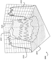
한 양태에서, 황색인대의 수술적 제거(surgical removal)를 위한 내시경 디바이스가, 환자 내에 삽입하기 위한 제1 단부, 수술을 조절하기 위한 제2 단부, 및 제1 단부와 제2 단부 사이에서 바디 내에 위치된 중공 코어를 가진 바디를 포함하되, 상기 바디는 사람 척추관 내에 삽입하도록 형태가 형성되고 크기가 정해진다. 또한, 내시경 디바이스는 제1 단부 상의 카메라를 포함할 수 있는데, 상기 카메라는 제1 단부로부터 돌출되는 관측시야(field of view)를 가지며 카메라는 중공 코어를 통해 제2 단부 상에서 디스플레이(display)에 결합된다. 내시경 디바이스는, 제2 단부에 결합되며 물의 열 가열(thermal heating)로 인해 세포외 매트릭스(extracellular matrix)의 파열을 통해, 바람직하게는 세포외 매트릭스의 직접적인 광분해(photodecomposition)에 의해, 황색인대를 제거하도록 선택된 적외선 파장에서 간섭광(coherent light)을 제공하도록 작동되는 레이저, 레이저의 출력을 중공 코어를 통해 내시경 디바이스의 바디의 제1 단부로 안내하기 위해 레이저에 결합된 레이저 단부, 및 카메라의 관측시야 내에서 한 표적을 향하는 출력 단부를 가진 광섬유를 포함할 수 있는데, 상기 광섬유는 출력 단부로부터 나온 빔(beam)을 가파른 면(steep side)을 가진 플루엔스 공간 패턴(fluence spatial pattern)으로 포커싱하여(focusing) 빔에 노출된 표적 표면의 주변의 비-제거된 조직(non-ablated)의 열을 감소시키기 위한 광학 요소를 포함한다. 또한, 내시경 디바이스는 레이저에 결합되고 레이저로부터 광섬유를 통해 황색인대의 커다란 조직(bulk tissue)을 제거하기 위한 플루엔스로 표적을 향해 일련의 펄스를 전달하도록 프로그래밍된 컨트롤러를 포함할 수 있다. In one aspect, an endoscopic device for surgical removal of a yellow ligament comprises a first end for insertion into a patient, a second end for manipulating the surgery, and a second end for manipulation of the ligament within the body within the body between the first end and the second end. A body having a hollow core positioned therein, the body being shaped and sized for insertion into a human spinal canal. The endoscope device may also include a camera on the first end, the camera having a field of view projecting from the first end, the camera being coupled to the display on the second end via a hollow core, do. The endoscopic device is attached to the second end and is removed by rupture of the extracellular matrix due to thermal heating of the water, preferably by direct photodecomposition of the extracellular matrix, A laser end coupled to the laser to direct the output of the laser through the hollow core to the first end of the body of the endoscopic device, The optical fiber may be configured to focus a beam from the output end into a fluence spatial pattern with a steep side (e.g., focusing optical element for reducing non-ablated heat around the target surface exposed to the beam. The. The endoscopic device may also include a controller coupled to the laser and programmed to deliver a series of pulses to the target with fluorescence to remove the bulk tissue of the yellow ligament from the laser through the optical fiber.
실시예들은 다음 특징들 중 하나 또는 그 이상의 특징을 가질 수 있다. 상기 광학 요소는 빔을 회절-제한된 빔(diffraction limited beam)으로 포커싱하는 광섬유의 출력 단부 상에 렌즈, 및/또는 광섬유의 출력 단부에서 빔의 발산(divergence)을 줄이도록 선택된 광섬유의 낮은 개구수(Numerical Aperture)를 포함할 수 있다. 플루엔스 공간 패턴은 실질적으로 톱-햇 패턴(top-hat pattern)일 수 있거나, 및/또는 플루엔스 공간 패턴의 피크(peak) 밑의 적어도 30 db의 측면 로브(side lobe)를 가질 수 있다. 레이저는 Ho:YAG 레이저를 포함할 수 있거나, 및/또는 약 2080 나노미터의 파장에서 광을 출력할 수 있다. 광섬유는 백만당 2 부분(part)을 초과하지 않는 저-하이드록실 함량(content)을 가질 수 있다. 내시경 디바이스는 Q-스위치를 추가로 포함할 수 있는데, 컨트롤러는 260 나노초보다 크지 않은 길이(반치전폭(full width half maximum))로 펄스를 전달하도록 구성된다. 컨트롤러는 140 마이크로초보다 크지 않은 길이(반치전폭)로 펄스를 전달하도록 구성될 수 있다. 내시경 디바이스는 바디의 제1 단부에서 염분 출력부(saline output)에 결합된 염분 공급원(saline source)을 추가로 포함할 수 있는데, 상기 염분 출력부는 광섬유의 출력 단부에서 표적을 향해 안내된다. 내시경 디바이스는 내시경 디바이스의 바디에 대해 출력 단부의 방향을 조절하기 위한 조종 메커니즘(steering mechanism)을 추가로 포함할 수 있다. Embodiments may have one or more of the following features. The optical element has a low numerical aperture of the optical fiber selected to reduce the divergence of the beam at the output end of the lens and / or the optical fiber on the output end of the optical fiber focusing the beam into a diffraction limited beam Numerical Aperture). The fluence spatial pattern may be substantially a top-hat pattern, and / or may have a side lobe of at least 30 db below the peak of the fluence spatial pattern. The laser may include a Ho: YAG laser, and / or may output light at a wavelength of about 2080 nanometers. The optical fiber may have a low-hydroxyl content that does not exceed two parts per million. The endoscopic device may further include a Q-switch, wherein the controller is configured to deliver the pulse with a length (full width half maximum) not greater than 260 nanoseconds. The controller can be configured to deliver pulses with a length not more than 140 microseconds (half full width). The endoscope device may further include a saline source coupled to a saline output at a first end of the body, the saline output portion being directed toward the target at an output end of the optical fiber. The endoscopic device may further include a steering mechanism for adjusting the direction of the output end relative to the body of the endoscopic device.
또 다른 양태에서, 황색인대의 수술적 제거를 위한 내시경 디바이스가, 환자 내에 삽입하기 위한 제1 단부, 수술을 조절하기 위한 제2 단부, 및 제1 단부와 제2 단부 사이에서 바디 내에 위치된 중공 코어를 가진 바디를 포함하되, 상기 바디는 사람 척추관 내에 삽입하도록 형태가 형성되고 크기가 정해진다. 또한, 내시경 디바이스는 제1 단부 상의 카메라를 포함할 수 있는데, 상기 카메라는 제1 단부로부터 돌출되는 관측시야를 가지며 카메라는 중공 코어를 통해 제2 단부 상에서 디스플레이에 결합된다. 내시경 디바이스는 제2 단부에 결합되며 물의 열 가열로 인해 세포외 매트릭스의 파열을 통해, 바람직하게는 세포외 매트릭스의 직접적인 광분해에 의해, 황색인대를 제거하도록 선택된 적외선 파장에서 간섭광을 제공하도록 작동되는 레이저, 레이저의 광학 공진기(optical resonator) 내에 Q-스위치를 추가로 포함할 수 있는데, 상기 Q-스위치는 레이저로부터 펄스형 레이저 출력(pulsed laser output)을 생성하도록 작동되며, 레이저의 출력을 중공 코어를 통해 내시경 디바이스의 바디의 제1 단부로 안내하기 위해 레이저에 결합된 레이저 단부, 및 카메라의 관측시야 내에서 한 표적을 향하는 출력 단부를 가진 광섬유, 및 레이저와 Q-스위치에 결합된 컨트롤러를 포함하되, 상기 컨트롤러는 레이저로부터 광섬유를 통해 황색인대의 커다란 조직을 제거하기 위한 플루엔스와 출력 단부로부터 나오는 빔에서 감소된 플루엔스 영역들이 표적의 주변(periphery) 주위에서 조직 영역들에 비-제거된 가열 손상(non-ablative heating damage)을 야기하는 것을 방지하도록 짧은 펄스 길이로 표적을 향해 일련의 Q-스위치된 펄스를 전달하도록 프로그래밍된다. In another aspect, an endoscopic device for surgical removal of a ligament ligament comprises a first end for insertion into a patient, a second end for manipulating the surgery, and a second end disposed within the body between the first end and the second end. A body having a core, the body being shaped and sized for insertion into a human spinal canal. The endoscopic device may also include a camera on the first end, the camera having an observation field projecting from the first end and the camera being coupled to the display on the second end through the hollow core. The endoscopic device is operatively associated with the second end and is operative to provide interference light at an infrared wavelength selected to remove the yellow ligament, preferably by rupture of the extracellular matrix due to thermal heating of the water, by direct photolysis of the extracellular matrix The laser may further include a Q-switch in an optical resonator of the laser, the Q-switch being operative to generate a pulsed laser output from the laser, An optical fiber having a laser end coupled to the laser for guiding to a first end of the body of the endoscopic device through the first end of the endoscope and an output end directed toward a target within the camera's field of view, Wherein the controller is configured to remove large tissue of the yellow ligament from the laser via an optical fiber In order to prevent the reduced fluence areas in the beam coming from the luen and the output end from causing non-ablative heating damage to the tissue areas around the periphery of the target, Lt; RTI ID = 0.0 > Q-switched < / RTI >
실시예들은 다음 특징들 중 하나 또는 그 이상의 특징을 가질 수 있다. Q-스위치는 음향-광학 감쇠기(acousto-optic attenuator)를 포함할 수 있다. 레이저는 Ho:YAG 레이저를 포함할 수 있다. 광섬유는 백만당 2 부분을 초과하지 않는 저-하이드록실 함량을 가질 수 있다. 컨트롤러는 20 나노초보다 크지 않은 길이(반치전폭)로 펄스를 전달하도록 구성되거나, 1 피코초보다 크지 않은 길이(반치전폭)로 펄스를 전달하도록 구성되거나, 및/또는 황색인대의 무열 제거(athermal ablation)를 위해 선택된 길이로 펄스를 전달하도록 구성될 수 있다. 내시경 디바이스는 내시경 디바이스의 바디에 대해 출력 단부의 방향을 조절하기 위한 조종 메커니즘을 추가로 포함할 수 있다. Embodiments may have one or more of the following features. The Q-switch may comprise an acousto-optic attenuator. The laser may include a Ho: YAG laser. The optical fiber may have a low-hydroxyl content that does not exceed two parts per million. The controller may be configured to deliver pulses at a length not greater than 20 nanoseconds (half full width), or configured to deliver pulses at a length not more than one picosecond (half full width), and / or athermal ablation ) ≪ / RTI > The endoscopic device may further include a steering mechanism for adjusting the direction of the output end with respect to the body of the endoscopic device.
또 다른 양태에서, 황색인대의 수술적 제거를 위한 내시경 디바이스가, 환자 내에 삽입하기 위한 제1 단부, 수술을 조절하기 위한 제2 단부, 및 제1 단부와 제2 단부 사이에서 바디 내에 위치된 중공 코어를 가진 바디를 포함하되, 상기 바디는 사람 척추관 내에 삽입하도록 형태가 형성되고 크기가 정해진다. 또한, 내시경 디바이스는 제1 단부 상의 카메라를 포함할 수 있는데, 상기 카메라는 제1 단부로부터 돌출되는 관측시야를 가지며 카메라는 중공 코어를 통해 제2 단부 상에서 디스플레이에 결합되고, 상기 내시경 디바이스는, 제2 단부에 결합되며 세포외 매트릭스의 직접적인 광분해를 통해, 바람직하게는 물의 열 가열로 인해 세포외 매트릭스의 파열에 의해, 황색인대를 제거하도록 선택된 자외선 파장에서 간섭광을 제공하도록 작동되는 레이저, 상기 레이저의 광학 공진기 내에 Q-스위치를 포함하되, 상기 Q-스위치는 레이저로부터 펄스형 레이저 출력을 생성하도록 작동되며, 레이저의 출력을 중공 코어를 통해 내시경 디바이스의 바디의 제1 단부로 안내하기 위해 레이저에 결합된 레이저 단부, 및 카메라의 관측시야 내에서 한 표적을 향하는 출력 단부를 가진 광섬유, 및 레이저와 Q-스위치에 결합된 컨트롤러를 포함할 수 있는데, 상기 컨트롤러는 레이저로부터 광섬유를 통해 황색인대의 커다란 조직을 제거하기 위한 플루엔스로 표적을 향해 일련의 Q-스위치된 펄스를 전달하도록 프로그래밍된다. In another aspect, an endoscopic device for surgical removal of a ligament ligament comprises a first end for insertion into a patient, a second end for manipulating the surgery, and a second end disposed within the body between the first end and the second end. A body having a core, the body being shaped and sized for insertion into a human spinal canal. The endoscope device may also include a camera on the first end, wherein the camera has an observer view projecting from the first end and the camera is coupled to the display on the second end through a hollow core, A laser that is coupled to the two ends and is operative to provide interference light at the ultraviolet wavelength selected to remove the yellow ligament by direct rupture of the extracellular matrix, preferably by rupture of the extracellular matrix due to thermal heating of water, Switch in the optical resonator of the endoscope device, the Q-switch being operative to generate a pulsed laser output from the laser, the laser output to the laser to guide the output of the laser through the hollow core to the first end of the body of the endoscope device The combined laser end, and the output directed to one target within the camera ' s field of view And a controller coupled to the laser and the Q-switch, wherein the controller is operable to transmit a series of Q-switched pulses from the laser through the optical fiber to the target with fluorescence to remove large tissue of the yellow ligament Lt; / RTI >
실시예들은 다음 특징들 중 하나 또는 그 이상의 특징을 가질 수 있다. 레이저는 주파수가 4배인(frequency quadrupled) Nd:YAG 레이저를 포함할 수 있으며, 약 266 나노미터의 파장에서 광을 출력할 수 있거나, 및/또는 300 나노미터 이하의 파장에서 광을 출력할 수 있다. Q-스위치는 음향-광학 감쇠기를 포함할 수 있다. 광섬유는 백만당 적어도 600 부분의 고-하이드록실 함량을 가질 수 있다. 컨트롤러는 20 나노초보다 크지 않은 길이(반치전폭)로 펄스를 전달하도록 구성될 수 있으며, 5 나노초보다 크지 않은 길이(반치전폭)로 펄스를 전달하도록 구성될 수 있고, 1 나노초보다 크지 않은 길이(반치전폭)로 펄스를 전달하도록 구성될 수도 있으며, 1 피코초보다 크지 않은 길이(반치전폭)로 펄스를 전달하도록 구성될 수 있거나, 황색인대의 무열 제거를 위해 선택된 길이로 펄스를 전달하도록 구성될 수 있다. 내시경 디바이스는 표적 표면과 광섬유의 출력 사이의 최소 분리 거리를 유지하기 위해 스탠드오프(standoff), 및/또는 바디의 제1 단부에서 염분 출력부에 결합된 염분 공급원을 추가로 포함할 수 있는데, 상기 염분 출력부는 광섬유의 출력 단부에서 표적을 향해 안내된다. 내시경 디바이스는 바디의 제1 단부에서 염분 출력부에 결합된 염분 공급원을 추가로 포함할 수 있는데, 상기 염분 출력부는 제1 단부 상에서 카메라를 향해 안내된다. 내시경 디바이스는 내시경 디바이스의 바디에 대해 출력 단부의 방향을 조절하기 위한 조종 메커니즘을 추가로 포함할 수 있다. 조종 메커니즘은 제1 단부 가까이 위치된 바디에 결합된 자석, 제1 단부와 제2 단부 사이에 결합되어 바디의 곡률을 조절하는 컨트롤 와이어, 및 바디의 외부에 결합되어 수술 공동 내에서 내시경 디바이스의 바디를 움직이도록 팽창될 수 있는 하나 또는 그 이상의 풍선 중 하나 이상을 포함할 수 있다. 조종 메커니즘은 바디의 곡률을 조절하도록 작동가능한 바디 내에서 복수의 동심적으로 배열되고 곡선의 튜브를 포함할 수 있다. 내시경 디바이스는 레이저에 의해 전달되는 광에너지로부터 표적 주위의 영역을 보호하도록 위치된 바디의 제1 단부에서 보호 실드, 표적 주위에서 상기 보호 실드의 위치를 조절하기 위해 바디의 제2 단부로부터 작동가능한 조종 메커니즘, 및/또는 카메라의 관측시야로부터 제1 단부 주위의 조직을 움직이도록 작동가능한 바디의 제1 단부 상에서 하나 또는 그 이상의 연장가능한 플랩을 추가로 포함할 수 있다. Embodiments may have one or more of the following features. The laser can include a frequency quadrupled Nd: YAG laser, can output light at a wavelength of about 266 nanometers, and / or can output light at a wavelength of less than 300 nanometers . The Q-switch may include an acousto-optic attenuator. The optical fiber may have a high-hydroxyl content of at least 600 parts per million. The controller may be configured to deliver pulses at a length not greater than 20 nanoseconds (half full width), and may be configured to transmit pulses at a length not greater than 5 nanoseconds (full width at half maximum) and not greater than 1 nanosecond And may be configured to deliver pulses at a length not more than one picosecond (half full width), or may be configured to deliver pulses at a selected length for heat removal of the yellow ligament have. The endoscopic device may further include a standoff to maintain a minimum separation distance between the target surface and the output of the optical fiber, and / or a saline source coupled to the saline output at the first end of the body, The saline output portion is guided from the output end of the optical fiber toward the target. The endoscopic device may further comprise a saline supply coupled to the saline output at a first end of the body, the saline output being directed toward the camera on a first end. The endoscopic device may further include a steering mechanism for adjusting the direction of the output end with respect to the body of the endoscopic device. The manipulation mechanism includes a magnet coupled to the body positioned near the first end, a control wire coupled between the first end and the second end to control the curvature of the body, and a control wire coupled to the exterior of the body, One or more balloons that can be inflated to move the balloon. The steering mechanism may comprise a plurality of concentrically arranged and curved tubes within a body operable to control the curvature of the body. The endoscopic device includes a protective shield at a first end of the body positioned to protect an area around the target from light energy transmitted by the laser, a controllable arm from the second end of the body for adjusting the position of the protective shield around the target, Mechanism, and / or one or more extendable flaps on the first end of the body operable to move tissue around the first end from an observation field of view of the camera.
본 명세서의 위에서 기술된 디바이스, 시스템, 및 방법들의 목적, 특징 및 이점들과 그 밖의 목적, 특징 및 이점들은 첨부도면을 참조하여 본 발명의 특정 실시예들을 기술한 하기 내용으로부터 더욱 자명하게 될 것이다. 도면은 실측으로 도시되지 않았으며, 본 명세서에 기술된 디바이스, 시스템 및 방법들의 원리를 예시하기 위한 것이다.
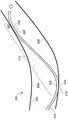
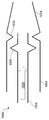
도 1은 수술용 관을 가로지르는 디바이스.
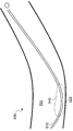
도 2는 수술용 관을 가로지르는 디바이스.
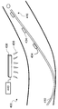
도 3은 컨트롤 와이어를 포함하는 수술용 관을 가로지르는 디바이스.
도 4는 자성 컨트롤을 포함하는 수술용 관을 가로지르는 디바이스.
도 5는 풍선을 포함하는 수술용 관을 가로지르는 디바이스.
도 6은 수술용 관을 가로지르기 위한 방법을 도시한 플로챠트.
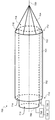
도 7은 전개되지 않은 상태에 있는 수술 도구를 도시한 도면.
도 8은 전개된 상태에 있는 수술 도구를 도시한 도면.
도 9는 전개된 상태에 있는 수술 도구를 도시한 도면.
도 10은 전개되지 않은 상태에 있는 전개 메커니즘을 도시한 도면.
도 11은 전개된 상태에 있는 전개 메커니즘을 도시한 도면.
도 12는 전개되지 않은 상태에 있는 전개 메커니즘을 도시한 도면.
도 13은 가요성 코팅을 가진 수술 도구를 도시한 도면.
도 14는 수술 장치를 도시한 도면.
도 15는 원위 단부에 수술 도구를 가진 수술 장치.
도 16은 원위 단부에 보호 실드를 가진 수술 장치.
도 17은 전개되지 않은 상태에 있는 복수의 플랩을 가진 내시경 바디를 도시한 도면.
도 18은 전개된 상태에 있는 복수의 플랩을 가진 내시경 바디를 도시한 도면.
도 19는 황색인대를 제거하기 위한 내시경 디바이스를 도시한 도면.
도 20은 표적 표면에 레이저를 위한 플루엔스 공간 패턴을 도시한 도면. The objects, features, and advantages of the devices, systems, and methods described above and other objects, features and advantages of the present invention will become more apparent from the following detailed description of certain embodiments of the invention with reference to the accompanying drawings . The figures are not drawn to scale and are intended to illustrate the principles of the devices, systems and methods described herein.
Figure 1 is a device across a surgical tube.
Figure 2 is a device across a surgical tube.
Figure 3 is a device across a surgical tube containing a control wire.
Figure 4 is a device across a surgical tube containing magnetic control.
Figure 5 is a device across a surgical tube containing a balloon.
6 is a flow chart showing a method for traversing a surgical tube.
Fig. 7 shows a surgical tool in a non-deployed state; Fig.
8 is a view showing a surgical tool in an unfolded state;
9 is a view showing a surgical tool in a deployed state;
Figure 10 shows a deployment mechanism in a non-deployed state;
11 shows a deployment mechanism in a deployed state;
Figure 12 shows a deployment mechanism in a non-deployed state;
Figure 13 shows a surgical tool with a flexible coating;
14 shows a surgical device.
15 is a surgical apparatus having a surgical tool at the distal end.
Figure 16 is a surgical device having a protective shield at the distal end.
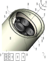
17 is a view showing an endoscope body having a plurality of flaps in an unfolded state;
18 shows an endoscope body having a plurality of flaps in a deployed state;
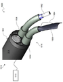
19 is a view showing an endoscope device for removing a yellow ligament;
Figure 20 shows a fluence space pattern for a laser on a target surface;
이제, 실시예들은 바람직한 실시예들이 도시된 첨부도면들을 참조하여, 밑에서 보다 상세하게 기술될 것이다. 본 명세서에 언급된 모든 문헌들은 본 명세서에서 전반적으로 참조문헌들로 인용된다. 단수형으로 기재된 표현들은 문맥에서 그 외에 달리 명확하게 언급되지 않는 한, 복수의 형태를 포함하는 것으로 이해되어야 하며 그 반대도 마찬가지이다. 문법적인 접속사들은, 문맥에서 그 외에 달리 언급되지 않는 한, 절, 문장, 단어들의 임의의 그리고 모든 조합들을 나타내기 위한 것이다. 따라서, 용어 "또는"은 일반적으로 "및/또는"을 의미하는 것으로 이해해야 한다. Embodiments will now be described in more detail below with reference to the accompanying drawings, in which preferred embodiments are shown. All publications mentioned herein are incorporated herein by reference in their entirety. The singular forms "a", "an," and "the" are intended to include the plural forms, unless the context clearly dictates otherwise and vice versa. Grammatical conjunctions are intended to denote clauses, sentences, and any and all combinations of words, unless the context otherwise requires. Accordingly, the term "or" should be understood to generally mean "and / or. &Quot;
본 명세서에 기술된 값들의 범위는 이들 값에만 제한하려는 것이 아니라, 본 명세서에서 그 외에 달리 언급되지 않는 한, 기술된 범위 내에 있는 임의의 그리고 모든 값들을 가리키기 위한 것이며, 이러한 범위 내에 있는 각각의 개별 값들은 본 명세서에서 개별적으로 언급되는 것과 같이 통합되어야 한다. 용어 "약", "거의" 등은, 수치 값들과 수반될 때, 당업자들에 의해 용이하게 이해되는 것과 같이 일정 편차를 가지는 것으로 이해되어야 한다. 본 명세서에서는, 수치 값 및/또는 값들의 범위가 오직 예로서 제공되는 것이며, 본 명세서에 기술된 실시예들의 범위에 제한되는 것이 아니라는 사실을 이해해야 한다. 본 명세서에서는, 임의의 그리고 모든 예, 또는 대표 예("예컨대", "가령" 등)가 사용되는데, 이들 또한 본 발명의 실시예들을 보다 잘 예시하기 위한 것이지 실시예들 또는 청구항들의 범위에 제한하려는 것이 아니다. 본 명세서에 기술된 어떠한 용어들도 실시예들을 실시하는 데 필수적인 임의의 요소들을 가리키지 않다는 것을 이해되어야 한다. It is to be understood that the range of values described herein is not intended to be limited only to these values, but rather to indicate any and all values within the stated ranges, unless otherwise stated herein, The individual values should be integrated as referred to individually herein. The terms " about ", "near ", and the like, when accompanied by numerical values, should be understood to have a certain variation, as readily understood by those skilled in the art. It should be understood that numerical values and / or ranges of values are provided herein by way of example only and are not intended to limit the scope of the embodiments described herein. Any and all examples, or representations (e.g., ""," such as "and the like) are used herein to better illustrate embodiments of the present invention but not to limit the scope of the embodiments or the claims. I do not want to. It is to be understood that no language is used herein to designate any element that is essential to the practice of the embodiments.
하기 내용에서, 용어, 가령, "제1", "제2", "상부", "바닥", "위", "아래", "뒤로", "앞으로" 등은 편의상 사용되는 용어들로서, 특별히 반대로 언급되지 않는 한, 이들에만 제한하려는 것이 아님을 이해해야 한다. In the following description, terms such as "first," "second," "upper," "bottom," "above," "below," "back," "forward, Unless stated otherwise, it should be understood that these are not intended to be limiting.
본 명세서에 기술된 디바이스, 시스템, 및 방법들은, 최소 침습 수술, 가령, 척추관 협착증(spinal stenosis)을 위한 수술 치료로서 척추강으로부터 황색인대의 레이저 제거에 있어서, 다양한 수술용 기구 및 이들의 적용분야에 관한 것이다. 하지만, 당업자는 그 밖의 적용분야도 가능하며 본 명세서에 기술된 시스템 및 방법들의 적용분야는 본 명세서에 기술된 적용분야들에만 국한되지 않는다는 것을 이해할 것이다. 예를 들어, 본 명세서에 기술된 디바이스, 시스템, 및 방법은 그 밖의 수술, 특히, 황색인대에 대해 유사한 특성을 가진 조직의 제거를 포함하는 수술에도 사용될 수 있다. 이와 동시에, 본 명세서에 기술된 기술들은 레이저 타입, 섬유 타입, 구동 기술 등의 적절한 변형을 통해 그 밖의 조직 타입의 제거에도 적절할 수 있다. 그 밖의 비-레이저-특정 도구(non-laser-specific tool) 및 특징부(feature)들도 그 밖의 최소 침습 수술에 광범위하게 적용될 수 있다. 또한, 수술 분야 외의 그 밖의 사용방법들도 가능하며, 이 방법들은 그 밖의 시스템, 가령, 배관(plumbing), 전기 시스템, 군사 또는 경찰 분야 및 그 외의 다른 분야(예컨대, 산업용 기계의 검사 또는 조작)들을 포함하지만 이들에만 제한되지는 않는다. The devices, systems, and methods described herein may be used in a variety of surgical instruments and their applications in laser ablation of the ligamentum flavum from the vertebral column as a minimally invasive procedure, such as surgical treatment for spinal stenosis . However, it will be understood by those skilled in the art that other applications are possible and that the applications of the systems and methods described herein are not limited to the applications described herein. For example, the devices, systems, and methods described herein may be used in other surgeries, particularly surgeries involving removal of tissue with similar characteristics to the yellow ligament. At the same time, the techniques described herein may be suitable for removal of other tissue types through appropriate modifications of the laser type, fiber type, drive technology, and the like. Other non-laser-specific tools and features can be extensively applied to other minimally invasive procedures. Other methods of use other than the surgical field are also possible and these methods may be applied to other systems, such as plumbing, electrical systems, military or police, and other fields (e.g., inspection or manipulation of industrial machines) But are not limited to these.
본 명세서에 기술된 시스템, 디바이스, 및 방법들은 특히 내시경과 함께 사용하도록 구성될 수도 있다. 내시경은 내시경의 바디 내에 하나 또는 그 이상의 동심적으로 배열되고 곡선의 튜브를 포함할 수 있는데, 이러한 튜브는 2014년 11월 21일 출원된 미국 특허출원번호 14/550,436호에 기술되어 있으며, 상기 미국 특허출원은 본 명세서에서 참조문헌으로 인용된다. 또 다른 양태에서, 상기 바디는, 내시경 바디, 가령, 내시경을 수술 환경에서 수술 부위, 예컨대, 척추관(surgical site)으로 전달하도록 사용되는 캐뉼라의 바디 또는 내시경 바디의 형태에 꼭 맞게 구성되도록 하기 위해, 하나 또는 그 이상의 미리-구부러진 부분 및/또는 조절 가능하게 굽어질 수 있는 부분을 가질 수 있다. 예를 들어, 한 실시예는 제1 단부와 제2 단부를 가진 가요성의 내시경 바디, 및 사전결정된 곡률반경과 사전결정된 강도를 가진 가요성의 내시경 바디의 제1 단부에 근접한 단부를 가진 가요성의 내시경 내에 있는 튜브를 포함하되, 상기 튜브는 중공 코어 및 수술 도구를 위해 상기 중공 코어로부터의 출구(exit)를 포함한다. 또한, 상기 실시예는 튜브와 동심 배열되고 튜브 외부에 슬라이딩 가능하게 배열된 슬리브를 포함할 수 있는데, 상기 슬리브는 튜브의 사전결정된 곡률반경보다 더 큰 곡률반경과 튜브의 사전결정된 강도보다 더 큰 강도를 가진 튜브의 단부에 근접한 말단 부분(terminal portion)을 가진다. 또한, 상기 실시예는 가요성의 내시경 바디의 제2 단부에 근접한 컨트롤 메커니즘을 가질 수 있는데, 슬리브를 튜브에 대해 축방향으로 이동시킴으로써 튜브의 단부의 곡률을 변경하도록 구성된 컨트롤을 포함한다. The systems, devices, and methods described herein may be particularly adapted for use with an endoscope. The endoscope may include one or more concentrically arranged and curved tubes within the body of the endoscope, such tubes being described in U.S. Patent Application Serial No. 14 / 550,436, filed November 21, 2014, The patent application is incorporated herein by reference. In yet another aspect, the body is adapted to conform to the shape of the body or endoscope body of the cannula used to deliver the endoscope body, e.g., the endoscope, from the surgical environment to a surgical site, such as a surgical site, One or more pre-bent portions and / or adjustably bendable portions. For example, one embodiment may include a flexible endoscope body having a first end and a second end, and a flexible endoscope body having an end proximate to a first end of the flexible endoscope body having a predetermined radius of curvature and a predetermined strength, The tube comprising an exit from the hollow core for a hollow core and a surgical tool. The embodiment may also include a sleeve concentrically arranged with the tube and slidably arranged outside the tube, the sleeve having a radius of curvature greater than a predetermined radius of curvature of the tube and a radius of curvature greater than the predetermined strength of the tube Lt; RTI ID = 0.0 > termini. ≪ / RTI > The embodiment also has a control mechanism close to the second end of the flexible endoscope body, which includes a control configured to change the curvature of the end of the tube by axially moving the sleeve relative to the tube.
이제, 최소 침습 수술 등에 사용하기 위한 다양한 가요성 도구들이 기술될 것이다. 가요성 도구들은 내시경, 캐뉼라, 또는 최소 침습 수술에 사용하기에 적합한 임의의 그 밖의 내시경 바디를 포함할 수 있다. 여기서, 2개 이상의 타입의 조종이 고려되는 것으로 이해할 수 있을 것이다. 한 양태에서, 내시경 바디 자체의 형태는 수술 부위에 대한 원하는 접근을 구현하도록 형성된다. 이는 한 정점(apex)을 가진 제1 곡선을 포함하는 복합 곡률(compound curvature) 또는 내시경 바디의 한 부분을 관 내의 안전한 위치에 배열하여 원위 단부를 보다 안정적이면서도 강제로 조작하기 위해 펄크럼(fulcrum)을 제공하도록 구성된 그 밖의 유사한 표면을 포함할 수 있다. 복합 곡률 내의 제2 곡선은 수술 도구를 척추관의 내벽들로부터 멀어지게 하거나 및/또는 표적 수술 부위를 향하게 하도록 기울어질 수 있다. 적절하게 구성된 복합 곡선(compound curve)이 수술 동안 원할 시에 또는 필요 시에 원위 단부에서 기계적 힘을 제공할 수 있도록 원위 단부를 원하는 대로 조절할 수 있게 한다. 제2 타입의 조종은, 보다 구체적으로, 수술 동안 원위 단부를 미세하게 조절하거나 배열시키는 데 관한 것이다. 따라서, 예를 들어, 정점 또는 그 밖의 지지 표면이 척추관의 내벽에 대해 견고하게 위치되면, 원위 단부는 본 발명에서 고려되는 것과 같이 하나 또는 그 이상의 조종 컨트롤과 시각적 네비게이션을 위한 카메라의 조합을 이용하여 조종될 수 있다. 조종을 위한 유저 컨트롤의 한 유용한 예는 미국 특허출원번호 14/550,436호에 제공되지만, 그 밖의 컨트롤 인터페이스와 메커니즘도 사용되거나 그 대신에 사용될 수 있다. Various flexible tools for use in minimally invasive surgery and the like will now be described. The flexible devices may include an endoscope, cannula, or any other endoscope body suitable for use in minimally invasive surgery. It will be appreciated that two or more types of steering are contemplated herein. In one aspect, the shape of the endoscope body itself is shaped to provide the desired access to the surgical site. This is a compound curvature comprising a first curve with one apex or a portion of the endoscope body arranged in a secure position in the tube to provide a fulcrum for more stable and forced manipulation of the distal end. Or other similar surface configured to provide a < / RTI > The second curve in the composite curvature can be tilted away from the inner walls of the spinal canal and / or toward the target surgical site. A properly configured compound curve allows the distal end to be adjusted as desired so that it can provide mechanical force at the distal end when needed or as needed during surgery. The second type of manipulation relates, more specifically, to fine-tuning or arranging the distal end during surgery. Thus, for example, if a vertex or other support surface is firmly positioned relative to the inner wall of the spinal canal, the distal end may be manipulated using one or more navigational controls and a combination of cameras for visual navigation, as contemplated herein It can be manipulated. One useful example of user control for steering is provided in U.S. Patent Application Serial No. 14 / 550,436, but other control interfaces and mechanisms may be used or used instead.
일반적으로, 캐뉼라는 종종 유체의 전달 또는 제거를 위해, 또는 데이터를 획득하기 위해 수술 부위로 삽입될 수 있는 튜브이다. 또한, 캐뉼라는 바늘 또는 그 밖의 수술 도구, 가령, 내시경의 내측 또는 외측 표면을 둘러쌀 수 있다. 최소 침습 수술 등에 있어서, 접촉이 방지되어야 하거나 최소화되어야 하는 민감하고 예민한 영역 주위에 수술 도구를 배치하고 조작하기 위해 가요성의 캐뉼라가 사용될 수 있다. 이를 위하여, 가요성의 캐뉼라는 기구(예컨대, 기다란 가요성의 기구 또는 도구)를 수술 부위 등 내에 바람직한 방향으로 편향되게 할 수 있다(bias). 이런 점에서, 비좁은(cramped) 또는 구불구불한(convoluted) 채널(예컨대, 수술 부위) 내에 가요성 도구(예컨대, 캐뉼라)를 전개시켜, 예민한 영역(예컨대, 부드러운 조직)과의 접촉을 방지하거나 또는 최소화시키고 및/또는 수술 부위 근처에 안전하고 안정적인 배열 부위를 제공하여 원위 단부를 안정화시키고 추가적인 하위의 기계적인 조종 및 그 밖의 조작을 위한 플랫폼을 제공하기 위하여, 다양한 디바이스, 시스템, 및 방법이 기술된다. 따라서, 본 명세서에 기술된 기술들 중 몇몇 기술, 특히, 내시경 디바이스의 곡률에 관한 기술은 내시경, 캐뉼라, 또는 이들의 특정 조합 또는 임의의 그 밖의 내시경 또는 복강경 바디에 동일하게 적용될 수 있다. In general, a cannula is often a tube that can be inserted into a surgical site for delivery or removal of fluid, or to acquire data. The cannula may also surround a needle or other surgical instrument, such as the inner or outer surface of the endoscope. In minimally invasive surgery and the like, a flexible cannula can be used to position and manipulate the surgical tool around a sensitive and sensitive area where contact should be prevented or minimized. To this end, the flexible cannula may bias the instrument (e.g., an elongated flexible instrument or instrument) in a desired direction within the surgical site, etc. [ In this regard, a flexible tool (e.g., a cannula) may be deployed within a cramped or convoluted channel (e.g., a surgical site) to prevent contact with a sensitive area (e.g., soft tissue) A variety of devices, systems, and methods are described for minimizing and / or providing a safe and stable location near the surgical site to stabilize the distal end and provide a platform for additional sub-mechanical manipulation and other manipulations . Thus, some of the techniques described herein, particularly those relating to the curvature of endoscopic devices, can be equally applied to endoscopes, cannulas, or any combination thereof, or any other endoscopic or laparoscopic body.
도 1은 수술용 관을 가로지르는 디바이스를 도시한다. 디바이스(100)는 상대적으로 구불구불한 또는 비좁은 채널(예컨대, 도면에 도시된 것과 같은 수술용 관(102))에서 전개되어, 채널의 민감하거나 예민한 영역과의 접촉이 최소화되거나 방지되도록 구성될 수 있다. Figure 1 shows a device across a surgical tube.
수술용 관(102)은 예를 들어 환자의 척추관일 수도 있는데, 디바이스(100)의 한 부분은 천골열공(sacral hiatus)을 지나 척추관 내로 삽입하도록 구성된다. 수술용 관(102)은 지지 조직 영역(104)과 연성 조직 영역(106)을 포함할 수 있다. 지지 조직 영역(104)은 연성 조직 영역(106)에 비해 상대적으로 경질 조직 영역일 수 있다. 지지 조직 영역(104)은, 예를 들어, 경막외 지방(epidural fat), 디스크(disc), 황색인대, 골(bone)들 중 하나 또는 그 이상을 포함할 수 있다. 연성 조직 영역(106)은 수술 부위의 임의의 상대적으로 민감하거나 또는 예민한 영역으로 간주될 수 있어서 접촉이 최소화되거나 방지되는 것이 바람직하다. 보다 일반적으로는, 수술용 관(102)은 조직의 다양한 타입 및 위치, 가령, 임의의 개수의 지지 조직 영역(104)과 연성 조직 영역(106)들로 특징지을 수 있는데, 수술 도구의 상응하는 위치들을 기술하기 위하여, 본 명세서에서는 각각의 조직 타입의 한 영역이 특별히 언급된다. The
수술용 관(102)은 사람 척추관, 가령, 사람 척추의 천골관(sacral canal) 또는 임의의 그 밖의 유사하게 구성된 해부학적 공간의 한 부분일 수 있다. 척추관을 위해, 수술 시작 지점(surgical entry point)은 천골열공에 상응할 수 있으며, 지지 조직 영역(104)은 골 조직(bone tissue)의 한 영역(예컨대, 척추의 배면 부분을 따라)에 상응할 수 있고, 연성 조직 영역(106)은 예컨대, 천골 신경(sacral nerve)의 노출된 신경근을 포함할 수 있다. 본 명세서에서 논의되는 것과 같이, 그 밖의 수술 또는 비-수술 관점도 가능하다. The
디바이스(100)는 복합 곡선(112)이 내부에 포함된 바디(110)를 가진 수술 도구(108)를 포함할 수 있다. 수술 도구(108)는 사용을 위해 수술 도구(108)가 위치될 때 환자 외부에 배열되는 컨트롤 단부(114), 및 사용을 위해 수술 도구(108)가 위치될 때 수술용 관(102)(예컨대, 척추관)의 내부에 위치되도록 구성된 원위 단부(116)를 추가로 포함할 수 있다. 일반적으로, 디바이스(100)는 수술용 관(102)의 연성 조직 영역(106)과 접촉을 피하도록 구성될 수 있다. 종래 기술의 몇몇 도구들은 특정 곡률을 용이하게 하는 것처럼 보이지만, 그 도구들은 수술용 관을 따라가도록 일반적으로 미리-구부러져 있거나(pre-curved) 삽입 동안 척추관에 의해 물리적으로 변형된다. 이러한 변형은 일반적으로, 최종 수술 표적을 향하는 임의의 수술 도구의 접근 궤적 또는 접촉 지점들의 위치에 무관하게, 형성된다. 이에 따라, 많은 바람직하지 못한 부작용들이 나타날 수 있는데, 가령, 연성 조직 또는 그 밖의 예민한 영역들과 접촉될 뿐만 아니라 원위 단부(114)에 의해 표적 부위에 접근이 제한된다. The
적절한 복합 곡률을 제공함으로써, 이러한 문제들은 완화될 수 있다. 예를 들어, 단부와 함께 표적에 압력을 제공하거나 또는 원위 단부(114)와 표적 표면, 가령, 수술용 관(102)의 내벽 사이를 원하는 만큼 분리된 상태를 유지하기 위해, 곡선의 한 굽힘부가 원위 단부(114)에 기계적 레버리지(mechanical leverage)를 지지하도록 위치될 수 있다. 한 양태에서, 복합 곡선(112)은 복합 곡선의 길이의 실질적인 부분을 따라 척추관의 배벽(dorsal wall)과 접촉하는 상태를 유지하도록 구성되고, 따라서, 원위 단부(114)를 반대편 벽으로부터 떨어진 한 위치에 유지하도록 구성될 수 있다. By providing appropriate composite curvature, these problems can be mitigated. For example, to provide pressure on the target with the end, or to maintain the desired separation between the
수술 도구(108)는 내시경, 내시경용 캐뉼라, 투관침(trocar) 등을 포함할 수 있는데, 이들에만 제한되는 것은 아니다. 뿐만 아니라 또는 그 대신에, 수술 도구(108)는 구불구불한 또는 비좁은 채널을 통해 안내될 수 있는 임의의 상대적으로 기다란 가요성의 기구를 포함할 수 있다. 따라서, 수술 도구(108)는, 내시경을 통해 배치하고 난 후, 체강(body cavity) 등 내에 조절 가능하게 위치될 수 있는 조종가능한 말단(steerable tip)을 가진 상대적으로 광범위한 카테고리의 도구로 분류되는 임의의 도구를 포함할 수 있다. The
뿐만 아니라 또는 그 대신에, 수술 도구(108)는 레이저, 광섬유, 카메라, 절삭 공구, 제거 공구, 고정 도구, 후킹 도구, 천공 도구, 로킹 도구, 실드, 안내 메커니즘, 재료 또는 유체 전달 시스템(예컨대, 기계식 또는 그 밖의 형태), 샘플링 디바이스 또는 트랜스듀서, 센서 등을 포함한다. 예를 들어, 한 양태에서, 디바이스(100)는 수술 레이저 및 상기 수술 레이저로부터 바디(110)를 통해 원위 단부(116)의 원위 말단(117)으로 광에너지를 전송하도록 위치된 광섬유를 포함한다. 또 다른 양태에서, 디바이스(100)는 원위 단부(116)에 결합되고 수술 표적(124)의 무선주파수 제거를 위해 작동가능한 전기수술식 무선주파수 디바이스를 포함한다. 이러한 구성요소(예컨대, 레이저, 절삭 공구, 전기수술식 무선주파수 디바이스 등)들은 수술 도구(108)의 원위 단부(116)에 결합될 수 있다. Alternatively, or in lieu of the
바디(110)는 천골열공을 지나 환자의 척추관 안에 삽입되도록 형태가 형성되고 크기가 정해질 수 있다. 한 양태에서, 바디(110)는 상기 통로를 통해 접근을 용이하게 하기 위해 3mm보다는 크지 않은 외측 직경을 가진다. 바디(110)는 내부에 배열된 하나 또는 그 이상의 경로 또는 작동 채널을 포함할 수 있는데, 여기서 도구 또는 그 밖의 물체 또는 커플링(예컨대, 데이터 및 전력 전달을 위한 전기선, 조종 및 그 밖의 조작을 위한 기계선 등)이 전개될 수 있다. 바디(110)는 가요성으로 구성될 수 있으며 조종가능할 수 있다. 바디(110)는 내부에 포함된 구성요소(예컨대, 동심 튜브)의 조절을 통해 꼭 맞을 수 있는 사전결정된 강도를 포함할 수 있다. The
복합 곡선(112)은 수술 도구(108)의 바디(110)에 배열될 수 있다. 복합 곡선(112)은 적어도 제1 굽힘부(118)와 제2 굽힘부(120)를 포함할 수 있다. The
제1 굽힘부(118)는 원위 단부(116)(즉, 원위 단부(116)의 원위 말단(117))이 수술을 위해 수술용 관(102)(예컨대, 척추관) 내의 수술 표적(124)에 위치될 때 수술용 관(102)의 지지 조직 영역(104)과 수술 도구(104) 사이에 접촉 지점(122)을 제공하도록 위치될 수 있다. 이런 식으로, 복합 곡선(112)의 제1 굽힘부(118)는 원위 말단(117)의 위치를 위해 기계적 지지(또는 고정)을 제공할 수 있다. 복합 곡선(112)의 제2 굽힘부(118)는 사용을 위해 수술 도구(108)가 제자리에 위치될 때 원위 단부(116)(및/또는 원위 말단(117))가 수술 표적(124)을 향해 안내되도록 위치될 수 있다. The
한 양태에서, 제1 굽힘부(118)는 사전결정된 강도를 가진다. 사전결정된 강도는 수술용 관(102)의 벽(126)과 바디(110) 사이의 적절한 짝 접촉(mating contact) 상태를 유지하여 수술용 관(102) 내에 그 밖의 조작을 견고하기 지지하도록 하기 위해 수술용 관(102)(예컨대, 척추관)의 원래 곡률(native curvature)로 변형되도록 선택될 수 있다. 수술용 관(102)의 원래 곡률로의 변형은 원위 단부(116)(또는 원위 단부(116)의 원위 말단(117))를 수술 표적(124)에 대해 고정된 위치에 유지시키기 위해 제1 굽힘부(118)의 제1 정점(128)과 제2 굽힘부(120)의 제2 정점(130) 사이의 한 영역에서 발생될 수 있다. 뿐만 아니라 또는 그 대신에, 사전결정된 강도는 제2 정점(130)이 수술용 관(102)의 벽(126)과 접촉하고 있는 상태를 유지하도록 선택될 수도 있다. 수학적으로 사용되는 것과 같이, "정점(apex)"은 특정 형태 또는 좌표 시스템에서 하나 또는 그 이상의 정확한 위치를 함축할 수 있다는 것을 이해해야 한다. 상기 용어는, 본 명세서에 기술된 수술용 관(102)과 마찬가지로, 기계적으로 접촉되고, 지지되거나 또는 조종되도록 형태가 형성된 수술 도구(110)의 한 길이를 따르는 임의의 영역을 가리키기 위한 것이다. In one embodiment, the
컨트롤 단부(114)는 디바이스(100) 및 연산 디바이스(152)와 통신 연결되어 결합된 컨트롤러(150)를 포함할 수 있다. 상기 컨트롤러는 본 명세서에 기술된 컨트롤 작동을 수행하도록 구성된 메모리(158)와 프로세서(156)를 포함할 수도 있다. The
일반적으로, 컨트롤러(150)는 디바이스(100)를 제어하도록 작동될 수 있다. 컨트롤러(150)는 본 명세서에 기술된 시스템(100)의 다양한 구성요소들을 제어하도록 구성된 프로세싱 회로 및/또는 소프트웨어의 임의의 조합을 포함할 수 있는데, 이러한 구성요소들은, 프로세서, 마이크로프로세서, 마이크로컨트롤러, 적용-특정 집적회로, 프로그래밍 게이트 어레이, 데이터베이스, 및 임의의 그 밖의 디지털 및/또는 아날로그 구성요소, 뿐만 아니라 이들의 조합과 함께, 컨트롤 시그널, 구동 시그널, 파워 시그널, 센서 시그널 등을 송수신하기 위한 입력 및 출력을 포함하지만 이들에만 제한되는 것은 아니다. 한 양태에서, 컨트롤러(150)는 마이크로프로세서 또는 그 밖의 프로세싱 회로(예컨대, 프로세서(156))를 포함할 수 있는데, 이러한 마이크로프로세서 또는 그 밖의 프로세싱 회로는 관련 기능, 가령, 작동 시스템을 실행하는 기능을 제공하고, 그래픽 유저 인터페이스(예컨대, 컨트롤러(150) 또는 또 다른 구성요소, 예컨대, 연산 디바이스(152)에 결합된 디스플레이에 대한)를 제공하며, 디바이스(100)의 작동을 위한 명령 및 규칙을 설정하고 실행하기에 충분한 연산 파워를 가진다. In general, the
연산 디바이스(152)는 디바이스(100) 또는 컨트롤러(150)를 조종, 모니터링, 통신, 제어 또는 상호작동하기 위해 유저에 의해 작동되는 임의의 디바이스 또는 디바이스들의 조합을 포함할 수 있다. 이는 데스크톱 컴퓨터, 랩탑 컴퓨터, 네트워크 컴퓨터, 태블릿, 스마트폰, 스마트 워치, 개인 휴대 정보 단말기, 또는 본 명세서에 기술된 요소들과 작동할 수 있는 임의의 그 밖의 디바이스를 포함할 수 있다. 연산 디바이스(152)는 유저 인터페이스(160), 가령, 수술용 관(102)의 한 모델(154)를 디스플레이하기 위한 그래픽 유저 인터페이스를 포함할 수 있다. 한 양태에서, 모델(154)은 수술용 관(102)의 2-차원 영상, 수술용 관(102)의 횡단면, 수술용 관(102)의 3-차원 영상 중 하나 또는 그 이상을 포함한다. 모델(154)은 수술 환자에 특정한 모델, 가령, 자기 공명 영상, x-레이 영상, 컴퓨터 액시얼 단층촬영 스캔, x-레이 컴퓨터 단층촬영 영상, 또는 환자의 해부학적 형태의 관련 부분들의 임의의 그 밖의 2-차원 또는 3-차원 영상으로부터 수술 환자에 특정한 모델일 수 있다. 또 다른 양태에서, 관련 기하학적 형상의 일반화된 모델이 사용될 수도 있다. 일반화된 모델의 경우, 복합 곡률의 바디를 적절하게 위치시키는 것이 보다 어려울 수 있으며, 철회(retraction) 및 수동 재-형성(passive re-shaping)에 의해 또는 곡률 컨트롤 메커니즘, 가령, 본 명세서에 기술된 메커니즘을 통해 초기 복합 곡선을 수술 동안 적절하게 변형시켜 보완하도록, 삽입 동안 시각적 안내가 사용될 수도 있다. The
뿐만 아니라 또는 그 대신에, 유저 인터페이스(160)는 텍스트 또는 커맨드 라인 인터페이스, 음성-제어 인터페이스, 및/또는 제스처-기반 인터페이스를 포함한다. 일반적으로, 유저 인터페이스는 유저 상호작동을 위해 연산 디바이스(152) 상에 적절한 디스플레이를 생성할 수 있다. 유저 인터페이스는 디바이스(100) 또는 그 밖의 공급원들로부터 데이터를 수신하는 연산 디바이스(152)에서 로컬 실행하는 애플리케이션에 의해 유지될 수 있다. 그 밖의 실시예들에서, 유저 인터페이스는 원격으로 작동되고 연산 디바이스(152) 상에 나타날 수 있는데, 가령, 웹 서버가 하나 또는 그 이상의 웹 페이지를 통해 정보를 제공하고, 이러한 정보는 연산 디바이스(152)를 실행하는 웹 브라우저 또는 이와 비슷한 클라이언트로 디스플레이될 수 있다. Additionally or alternatively, the
그 밖의 구성요소, 예컨대, 그 밖의 하드웨어, 가령, 입력 디바이스, 가령, 키보드, 터치패드, 마우스, 스위치, 다이얼, 버튼, 센서 뿐만 아니라 출력 디바이스, 가령, 디스플레이, 스피커 또는 그 밖의 오디오 트랜스듀서, 발광 다이오드 등도 포함될 수도 있다. 뿐만 아니라 또는 그 대신에, 그 밖의 구성요소는 예컨대, 외부 컴퓨터, 외부 하드웨어, 외부 기기 또는 데이터 획득 시스템 등에 연결하기 위한 다양한 케이블 커넥션 및/또는 하드웨어 어댑터를 포함한다. Such as a keyboard, a touchpad, a mouse, a switch, a dial, a button, a sensor, as well as an output device such as a display, a speaker or other audio transducer, a light emitting device A diode and the like may also be included. As well as or instead, other components include various cable connections and / or hardware adapters for connecting to, for example, an external computer, external hardware, external equipment or a data acquisition system.
뿐만 아니라 또는 그 대신에, 컨트롤러(150)는 수동 컨트롤러, 예컨대, 컨트롤러(150)가 휴대용 디바이스를 포함하거나 휴대용 디바이스에 일체로 구성된 수동 컨트롤러를 포함할 수 있는데, 이러한 수동 컨트롤러는 컨트롤러(150) 상의 버튼 또는 조이스틱이 물리적으로 움직이면 이에 상응하게 수술 도구(108)가 움직이게 된다. Additionally or alternatively, the
사용 시에, 디바이스(100)는 디바이스(100)가 전개된 상태에 있을 때(즉, 수술 도구(108)의 원위 말단(117)이 수술 표적(124)의 작동 범위 내에 있을 때) 접촉 지점(122)이 지지 조직 영역(104)에 배열되도록 전개 전에 변형될 수 있다. 이러한 변형은 수술용 관(102)의 하나 또는 그 이상의 모델(154)(또는 영상, 예컨대, x-레이 영상, MRI 영상 등)에 따라 구현될 수 있다. 몇몇 실시예들에서, 기존의 디바이스(100)를 변형하는 대신, 한 디바이스가 수술용 관(102)의 모델(154)에 따라 본 명세서에 기술된 기하학적 형상으로 제작될 수 있다. 임의의 경우에서, 전개 동안의 이러한 형상은 임의의 노출된 연성 조직 영역(106)이 수술 도구(108)를 압축, 스크래칭, 또는 접촉되는 바람직하지 못한 부작용을 완화하거나 제거할 수 있다. In use, the
도 2는 수술용 관을 가로지르는 디바이스를 도시한다. 도 2에서 디바이스(200)는 도 1에 도시된 디바이스와 유사하지만, 상기 디바이스(200)는 복합 곡선(212)을 가진 바디(210)를 포함하며, 제1 굽힘부(218)의 제1 정점(228)과 제2 굽힘부(220)의 제2 정점(230) 두 모두 수술용 관(202)의 벽(226)과 접촉된다. 구체적으로, 제1 정점(228)은 제1 접촉 지점(222)에서 수술용 관(202)의 벽(226)과 접촉되고 제2 정점(230)은 제2 접촉 지점(223)에서 수술용 관(202)의 벽(226)과 접촉된다. 이는 두 정점(228, 230)이 수술용 관(202)의 벽(226)과 접촉 상태를 유지하는 바디(210)(예컨대, 복합 곡선(212))의 사전결정된 강도에 의해 야기될 수 있다. Figure 2 shows a device across a surgical tube. The
상기 도면들은 각각 수술용 관의 한 접촉 지점과 두 접촉 지점을 도시하고 있지만, 당업자라면 그보다 많은 접촉 지점들도 가능하다는 것을 이해할 것이다. 예를 들어, 한 실시예는 복합 곡선에서 2개보다 많은 굽힘부를 포함할 수 있거나, 또는 복합 곡선은 수술용 관(202)의 내부의 부분들을 따르도록 조절될 수 있는데, 예컨대, 일정 길이의 바디(210)를 따라 수술용 관(202)의 한 영역과 접촉하거나 이 영역에 근접한 상태를 유지하도록 조절될 수 있다. 뿐만 아니라 또는 그 대신에, 이는 수술용 관의 벽과 접촉하는 2개보다 많은 접촉 지점일 수 있는데, 예컨대, 하나 또는 그 이상의 접촉 지적들이 복합 곡선 내에 포함된 각각의 굽힘부와 연결될 수 있다. 그에 따라, 임의의 개수의 가능한 굽힘부 및 이에 상응하는 접촉 지점들이 가능하다. 한 양태에서, 모든 접촉 지점들은 지지 조직 영역(들) 내에 위치되도록 구성된다. 하지만, 일반적으로는, 본 명세서에 기술된 연성 조직 영역과 접촉되는 것을 피하는 것이 바람직할 수 있으나, 복합 곡선 내에 포함된 하나 또는 그 이상의 굽힘부와 연결된 하나 또는 그 이상의 접촉 지점들은, 대신에, 연성 조직 영역, 지지 조직 영역과 연성 조직 영역의 임의의 조합, 또는 수술용 관(202) 내의 다른 위치에 배열될 수도 있다. While the figures each show one contact point and two contact points of the surgical tube, it will be understood by those skilled in the art that more contact points are possible. For example, one embodiment may include more than two bends in the composite curve, or the composite curve may be adjusted to follow portions of the interior of the
한 양태에서, 수술용 관의 기하학적 형상에 따라, 각각의 접촉 지점이 지지 조직 영역에 위치되도록 배열되는 것이 가능하지 않을 수도 있다. 상기 경우에서, 위에서 언급된 기술들에 대해 개선된 기술들이 사용될 수 있는데, 이러한 2개의 예들이 밑에 제공된다. In one version, depending on the geometry of the surgical tube, it may not be possible for each contact point to be arranged in the support tissue region. In this case, improved techniques can be used for the above-mentioned techniques, two examples of which are provided below.
제1 예로서, 접촉 지점들은 몇몇 경우에서 우선 순위를 가질 수 있으며, 주된 지점 또는 접촉 지점(즉 최우선 순위를 가진 지점)이 지지 조직 영역 위에 위치될 수 있다. 몇몇 실시예들에서, 접촉 지점들은 디바이스가 전개된 상태에 있을 때 접촉 지점에서 예상 압력에 따라 우선 순위를 가질 수 있다(즉 고압 지점들이 우선 순위를 가진다). 한 접촉 지점에서 예상 압력은 모델(예컨대, 수학적 모델, 물리적 프로토타입, 이들의 조합 등) 또는 임의의 그 밖의 수단에 의해 결정될 수 있다. 몇몇 실시예들에서, 접촉 지점들은 특정 환자에 대해 해부학적 중요성에 따라 우선 순위를 가질 수 있다. 뿐만 아니라 또는 그 대신에, 접촉 지점들의 우선 순위를 두기 위한 그 밖의 방법들도 가능하다. As a first example, the contact points may have priority in some cases and the main point or point of contact (i.e. the point with the highest priority) may be located above the support tissue area. In some embodiments, the contact points may have priority over the expected pressure at the point of contact when the device is in the deployed state (i.e., the high pressure points have priority). The expected pressure at a point of contact may be determined by a model (e.g., mathematical model, physical prototype, combination thereof, etc.) or any other means. In some embodiments, the points of contact may have priorities according to anatomical importance to a particular patient. As well as or instead, other methods for prioritizing contact points are possible.
제2 예로서, 몇몇 타입의 연성 조직에 대해, 허용가능한 압력 임계값이 제공될 수 있는데, 이 임계값 밑에서는 바람직하지 못한 부작용들이 최소화되거나 제거될 수 있다. 일반적으로, 상기 허용가능한 압력 임계값은 디바이스에 의해 접촉되는 연성 조직의 타입에 좌우될 수 있다. 하나 또는 그 이상의 접촉 지점들이 연성 조직에 배열되어야 할 때, 본 명세서에 기술된 기술이 가능한 최대한 전체 압력이 허용가능한 임계값 밑에 제공되도록 연성 조직 영역 상에서 디바이스로부터 압력을 분배하도록 사용될 수 있다. 따라서, 디바이스의 한 곡선이 벽 내의 특정 영역에 배열되도록 구성될 수 있으며, 수술용 관에 일치하도록 구성된 강도, 길이의 더 큰 부분을 따라 접촉 표면을 분배하여 따라서 길이의 더 큰 부분을 따라 접촉 지점을 분배하도록 선택된 형태를 가질 수 있다. As a second example, for some types of soft tissue, an acceptable pressure threshold may be provided, below which undesirable side effects may be minimized or eliminated. Generally, the allowable pressure threshold may depend on the type of soft tissue contacted by the device. When one or more contact points are to be arranged in the soft tissue, the techniques described herein can be used to dispense pressure from the device on a soft tissue area such that as much of the total pressure as possible is provided below an acceptable threshold. Thus, a curve of the device can be configured to be arranged in a specific area within the wall, and can be configured to distribute the contact surface along a larger portion of its length, Lt; RTI ID = 0.0 > a < / RTI >
도 3은 컨트롤 와이어를 포함하는 수술용 관을 가로지르는 디바이스를 도시한다. 구체적으로, 상기 도면에서 디바이스(300)는 위에서 기술된 디바이스들과 유사하지만, 상기 디바이스(300)는 바디(310)에 대한 원위 단부(316)의 한 부분(예컨대, 원위 말단(317))을 조절하기 위해 원위 단부(316)와 컨트롤 단부 사이에 결합된 컨트롤 와이어(332)를 포함한다. 컨트롤 와이어(332)는 디바이스(300)의 움직임을 조절하기 위해, 예를 들어, 디바이스(300)가 연성 조직으로부터 멀어지도록 굴절시키거나, 위에서 기술된 바람직하지 못한 부작용들을 완화시키기 위해 디바이스(300)의 바디(310)(예컨대, 하나 또는 그 이상의 고정 지점(333)에서)에 기계적으로 결합될 수 있다. Figure 3 shows a device across a surgical tube containing a control wire. Specifically,
하나 또는 그 이상의 고정 지점(333)은 디바이스(300)의 바디(310)를 따라 임의의 위치에, 예를 들어, 디바이스(300)의 원위 단부(316)에 위치될 수 있다. 뿐만 아니라 또는 그 대신에, 컨트롤 와이어(332)는 바디(310)의 길이를 따라 다양한 그 밖의 커플링에 의해 디바이스(300)의 바디(310)의 기계적으로 결합될 수 있다. 이러한 커플링은, 예를 들어, 컨트롤 와이어(322)가 통과될 수 있는 루프를 포함할 수 있다. The one or more anchoring points 333 may be located at any location along the
뿐만 아니라 또는 그 대신에, 컨트롤 와이어(332)는 디바이스(300)의 근위 단부에서 컨트롤 유닛(334) 또는 컨트롤러(예컨대, 위에 기술된 컨트롤러와 유사한)에 기계적으로 결합될 수 있다. 몇몇 실시예들에서, 컨트롤 유닛(334)은 다이얼, 트리거, 또는 운영자가 다양한 미리-선택된 수준의 인장력을 컨트롤 와이어(332)에 제공할 수 있도록 하는 유사한 컨트롤을 포함할 수 있다. 몇몇 실시예들에서, 컨트롤 유닛(334)은 운영자가 연속적으로 변경되는 수준의 인장력을 컨트롤 와이어(332)에 제공할 수 있게 할 수도 있다. 인장력을 컨트롤 와이어(332)에 제공하면, 디바이스(300)의 운영자는 디바이스의 형태를 변경할 수도 있다. 상기 도면에서는, 예를 들어, 디바이스(300)가 컨트롤 와이어(332)에 인장력이 거의 없거나 또는 아예 없는 상태로 예시된다. 컨트롤 와이어(332)에 인장력을 증가시킴으로써, 디바이스(300)는 연성 조직으로부터 굴절되어, 연성 조직과 접촉하는 것에 관련된 임의의 바람직하지 못한 부작용을 피할 수도 있다. The
보다 일반적으로, 하나 또는 그 이상의 컨트롤 와이어(원하는 대로 배치하기 위한 자유도에 따라)를 사용하여 기다란 부재의 형태를 조절하기 위한 다양한 기술들이 알려져 있는데, 이들 중 임의의 기술은 본 명세서에 기술된 것과 같은 시스템으로 사용하기에 적합할 수 있다. 또한, 기능을 예시하기 위해 컨트롤 와이어(332)가 바디(310)의 외부에 도시되었지만, 컨트롤 와이어(332)는 척추관 내에 조직과 해부학적 구성에 노출을 피하기 위하여 바디(310)의 내부에 위치되는 것도 유용할 수 있다는 것을 이해해야 할 것이다. More generally, various techniques are known for controlling the shape of elongated members using one or more control wires (depending on the degree of freedom to place them as desired), any of which may be used May be suitable for use as a system. Also, although
도 4는 자성 컨트롤을 포함하는 수술용 관을 가로지르는 디바이스를 도시한다. 구체적으로, 상기 도면에서 디바이스(400)는 위에서 도시된 디바이스들과 유사하지만, 디바이스(400)는 바디(410)에 결합된 하나 또는 그 이상의 자석(434)을 포함한다. 자석(434)은 바디(410)의 원위 단부(416)에 또는 원위 단부(416) 근처에, 또는 바디(410)를 따라 다른 위치에 배열될 수 있다. 자석(434)은 자기장(438)을 제공하여 디바이스(400)를 조절하도록 구성된 외부 자석(436)과 함께 작동할 수 있다. 예를 들어, 한 실시예에서, 전개 전에 또는 전개 동안, 자기장(438)은 외부 자석(436)에 의해 제공되어 자석(434)이 원하는 방향으로, 예컨대, 디바이스(400)를 연성 조직으로부터 멀어지도록 굴절시키는 방향으로 힘을 제공하게 할 수 있다. 몇몇 실시예들에서, 자기장(438)의 크기 및/또는 방향은 외부 컨트롤러(440)(예컨대, 위에서 기술된 컨트롤러와 유사한 컨트롤러)에 의해 조절될 수 있다. Figure 4 shows a device across a surgical tube containing magnetic control. In particular, the
도 5는 풍선을 포함하는 수술용 관을 가로지르는 디바이스를 도시한다. 구체적으로, 상기 도면에서 디바이스(500)는 위에서 기술된 디바이스들과 유사하지만, 상기 디바이스(500)는 하나 또는 그 이상의 풍선(540) 또는 그 밖의 탄성 또는 비탄성의 팽창성 막을 포함하는데, 이들은 바디(510)의 외부에 결합되고 바디(510)를 수술용 관(502) 내에서 움직이도록 팽창될 수 있다. 풍선(540)은 연성 조직과 접촉을 방지하거나 및/또는 디바이스(500)를 조절하기 위한 요소로서 작용할 수 있다. 풍선(540)은 디바이스의 전개 전에 또는 전개 동안에 원하는 크기로 팽창될 수 있다. 팽창되었을 때, 풍선(540)은 접촉 지점(522)에서 디바이스(500)의 바디(510)의 접촉력을 분배하여, 접촉 지점(522)에서 전체적으로 낮은 압력이 되도록 작동될 수 있다. 몇몇 실시예들에서, 풍선(540)은 디바이스(500)의 바디(510)를 따라 한 위치에 배열될 수 있는데, 상기 위치에서 접촉 지점(522)은 디바이스(500)이 전개된 상태에 있을 때 발생된다. 상기 위치는 수학적 모델(예컨대, 환자의 키, 몸무게 등에 따라)에 의해 및/또는 수술용 관(502)의 하나 또는 그 이상의 영상의 검사로부터 식별될 수 있다. 따라서, 풍선(540)은, 수술 도구의 연장된 단부를 수술 표적 근처로 이동, 배치, 또는 안정화시키기 위해, 혹은 그 밖의 경우 디바이스(500)를 수술용 관(502) 내에 배치하거나 조작하기 위하여, 디바이스(500)의 바디(510)의 한 길이를 따라 레버리지를 제공하기 위해 접촉 지점(예컨대, 접촉 지점(522)을 구현하도록 사용될 수 있다. 일반적으로, 풍선(540)은 특정 용도를 위해 적절한 것과 같이 디바이스(500)의 바디(510)의 길이를 따라 팽창, 수축되고 이동될 수 있다. 몇몇 실시예들에서, 풍선(540)은 외부 컨트롤러(예컨대, 위에서 기술된 컨트롤러와 유사한 컨트롤러)에 의해 조절될 수 있다. Figure 5 shows a device across a surgical tube containing a balloon. The
위에서 기술한 것과 같이, 복합 곡선을 가진 디바이스는 바디 내에 하나 또는 그 이상의 동심적으로 배열되고 곡선의 튜브들을 추가로 포함할 수 있다. 한 양태에서, 동심적으로 배열되고 곡선의 튜브들은 제1 굽힘부와 제2 굽힘부 중 하나 이상의 굽힘부의 곡률을 조절하도록 작동 가능하다. As described above, a device with complex curves can additionally include one or more concentrically arranged and curved tubes within the body. In one aspect, the concentrically arranged and curved tubes are operable to adjust the curvature of at least one of the first bend and the second bend.
상기 실시예들에서, 기술들을 조종, 배치, 및 조절하는 다양한 조합들이 사용될 수 있다. 따라서, 디바이스는 위에서 기술된 기술들의 임의의 조합, 즉, 자석, 컨트롤 와이어, 풍선, 및 동심 튜브, 뿐만 아니라 임의의 그 밖의 적절한 기술 및 이들의 임의의 조합을 사용할 수 있다. 이와 유사하게, 한 기술은 디바이스(500)의 바디(510) 내의 조절가능한 전체(aggregate) 복합 곡선으로 구현하도록 사용되고 제2 기술은 수술 도구 등이 장착되는 원위 단부의 위치 또는 배열방향을 미세하게 조절하도록 사용될 수 있다. 이러한 조합 및 변형예들은 모두 본 발명의 범위 내에 있다. In the above embodiments, various combinations of manipulating, arranging, and adjusting techniques may be used. Thus, the device may use any combination of the techniques described above, namely magnets, control wires, balloons, and concentric tubes, as well as any other suitable technique and any combination thereof. Similarly, one technique may be used to implement an adjustable aggregate curve within the
도 6은 수술용 관을 가로지르기 위한 방법을 도시한 플로챠트이다. 6 is a flowchart showing a method for traversing a surgical tube.
단계(602)에 도시된 것과 같이, 방법(600)은 환자의 수술용 관의 모델을 제공하는 단계를 포함할 수 있다. 수술용 관은 수술 시작 지점, 지지 조직 영역, 연성 조직 영역, 및 수술 표적을 포함할 수 있다. 또한, 수술용 관은 곡률을 포함할 수도 있다. 상기 모델은 본 명세서에 기술된 모델 중 임의의 모델을 포함할 수 있는데, 이러한 모델은 원하는 형태에 근사화시키기에 적절한 일반적인 모델 또는 특정 환자의 수술용 관의 2-차원 또는 3-차원 영상을 포함하지만 이들에만 제한되지는 않는다. As shown in
단계(604)에 도시된 것과 같이, 방법(600)은 복합 곡선 내에 원위 말단을 가진 수술 도구를 형성하는 단계를 포함할 수 있다. 수술 도구는 본 명세서에 기술된 것과 같은 임의의 수술 도구일 수 있는데, 내시경 및 내시경용 캐뉼라 중 하나 이상일 수 있다. As shown in
복합 곡선은, 원위 말단이 수술을 위해 수술 표적에 위치될 때, 수술용 관의 지지 조직 영역과 수술 도구 사이에 접촉 지점을 제공하도록 위치된 제1 굽힘부를 포함할 수 있다. 제1 굽힘부는 원위 말단의 한 위치를 위해 기계적 지지를 제공할 수 있다. 복합 곡선은 원위 말단이 수술 표적을 향해 안내되도록 위치된 제2 굽힘부를 추가로 포함할 수 있다. 뿐만 아니라 또는 그 대신에, 한 실시예에서, 제2 굽힘부는 수술용 관의 벽과 디바이스 사이에 보완적인 접촉 지점을 제공하여 수술을 위해 디바이스를 추가로 지지하고 안정화시킬 수 있다. The composite curve may include a first bend positioned to provide a point of contact between the support tissue region of the surgical tube and the surgical tool when the distal end is positioned in the surgical target for surgery. The first bend can provide mechanical support for one position of the distal end. The composite curve may further include a second bend positioned so that the distal end is directed towards the surgical target. As well as or instead, in one embodiment, the second bend can provide a complementary contact point between the wall of the surgical tube and the device to further support and stabilize the device for surgery.
단계(606)에 도시된 것과 같이, 방법(600)은 연성 조직 영역과 수술 도구 사이의 위치에 풍선을 배치하는 단계를 포함할 수 있다. 이 단계는, 고정되고 결부된 풍선이 적절한 위치에 있을 때까지 수술 디바이스의 바디를 움직이거나 또는 풍선이 적절한 위치에 배치될 때까지 바디를 따라 풍선을 움직이는 것을 포함할 수 있다. As shown in
단계(608)에 도시된 것과 같이, 방법(600)은 풍선을 팽창시켜 연성 조직 영역과 수술 도구 사이에 연성 배리어(soft barrier)를 제공하는 단계를 포함할 수 있다. 어떻게 배치되던 간에, 풍선은 보다 일반적으로 척추관 내에 위치되는 바디 또는 수술 도구를 위해 원하는 기계적 결과를 구현하기 위하여, 팽창되고, 수축되거나, 또는 조절될 수 있다. As shown in
단계(610)에 도시된 것과 같이, 방법(600)은 수술 도구를 조종하는 단계를 포함할 수 있다. 이 단계는 위에서 기술된 것과 같이 미세하게 조종하는 것을 포함하는데, 예컨대, 수술 표적에 대해 원하는 위치를 구현하기 위해 수술 도구의 원위 말단의 한 위치를 조절하는 것을 포함할 수 있다. 또한, 이 단계는 수술 도구의 굽힘부 또는 굽힘부의 단부의 조절에 의해 전체 디바이스를 척추관 또는 그 밖의 수술 공동(surgical cavity) 내의 원하는 위치에 배치하는 일반적인 조종 단계를 포함할 수 있다. 따라서, 수술 도구의 원위 말단을 조종하는 것은 원위 말단이 수술 표적을 향하도록 조종하며, 원위 말단이 연성 조직 영역으로부터 멀어지도록 조종하거나 또는 그 밖에 수술 도구의 바디 또는 수술 도구의 원위 단부 또는 원위 말단을 조종하여 원하는 대로 수술하는 것을 포함할 수 있다. 이러한 조종은 본 명세서에 기술된 기술들 중 임의의 기술을 이용하여 수행될 수 있다. 따라서, 예를 들어, 원위 말단을 조종하는 것은 수술 도구에 기계적으로 결합된 와이어를 사용하여 원위 단부를 컨트롤 단부로부터 원위 말단으로 조종하는 것을 포함할 수 있다. 뿐만 아니라 또는 그 대신에, 원위 말단을 조종하는 것은, 외부 자기장을 제공하여 수술 도구에 결합된 하나 또는 그 이상의 자석을 움직이도록 힘을 제공하는 것을 포함할 수도 있다. 뿐만 아니라 또는 그 대신에, 원위 말단을 조종하는 것은 상이한 곡률 또는 강도를 가진 수술 도구 내에 하나 또는 그 이상의 동심적으로 배열된 튜브를 회전시키거나 또는 병진운동시키는 것을 포함할 수 있다. As shown in
이제, 최소 침습 수술 등에 사용하기 위한 도구(예컨대, 가요성 도구)의 또 다른 실시예가 기술되는데, 이러한 도구는, 예컨대, 수술 동안에 직면하는 장애(obstruction)에 의해 나타나는 합병증들을 완화하기 위해, 플랩을 가진 수술 도구를 포함한다. Now, another embodiment of a tool (e.g., a flexible tool) for use in minimally invasive surgery or the like is described, which may include a flap, for example, to alleviate complications caused by obstructions encountered during surgery Includes surgical tools.
도 7은 전개되지 않은 상태에 있는 수술 도구를 도시한다. 수술 도구(700)는 성긴 물질(loose matter)을 포함하는 수술 부위에 전개하도록 구성된 디바이스를 포함할 수 있다. 수술 도구(700)는 수술 표적 근처에 있는 장애들에 의해 야기된 문제들을 완화하도록 구성될 수 있다. Figure 7 shows a surgical instrument in a non-deployed state. The
수술 도구(700)는 제1 튜브(702), 복수의 플랩(704), 제2 튜브(706), 및 컨트롤러(708)를 포함할 수 있다. 또한, 본 명세서에서는 복수의 플랩(704)이, 본 명세서에 기술된 것과 같이 수술 도구(700)의 바디로부터 멀어지도록 연장되고 외부를 향해 연장되는 기능을 기술하기 위해, "연장가능한 플랩(extendable flap)"으로 지칭될 수 있다. The
제1 튜브(702)는 근위 단부(710), 원위 단부(즉, 상기 도면에 도시된 제1 원위 단부(712)), 중공 코어(714), 및 제1 원위 단부(712)에서 중공 코어(714)로부터의 출구(716)를 포함할 수 있다. 따라서, 제1 튜브(702)는 중공 코어(714)가 내부에 형성된 중공의 실질적으로 원통형의 구조를 포함할 수 있으며, 제2 튜브(706)는 제1 튜브(702)의 중공 코어(714) 내에 배열된다. 한 양태에서, 제2 튜브(706)도 중공으로 구성되며 이에 따라 자체적인 내부 중공 코어(715)를 포함한다. The
제1 튜브(702)의 중공 코어(714)와 제2 튜브(706)의 내부 중공 코어(715) 외에도, 수술 도구(700)는 제1 튜브(702)의 내부와 제2 튜브(706)의 외부 사이에 배열된 용적 즉 튜브(702, 706) 사이의 빈 공간(void), 또는 원하는 대로 사용하기 위해 임의의 그 밖의 적절한 크기를 가지며 임의의 그 밖의 적절한 위치에 의해 형성된 제2 중공 코어(724)를 포함할 수 있다. 제2 중공 코어(724)는 제1 튜브(702)의 중공 코어(714)와 제2 튜브(706)의 내부 중공 코어(715) 중 하나 또는 그 이상에 대해 평행할 수 있다. 그 외에도, 제2 중공 코어(724)는 제1 튜브(702)와 제2 튜브(706) 중 하나 또는 그 이상의 튜브에 의해 형성될 수 있지만, 예컨대, 복수의 보조 도구를 위해, 내부에 복수의 추가적인 중공 코어를 형성하는 경로를 포함할 수도 있다. In addition to the
수술 도구(700)에서, 근위 단부(710)는 수술 동안 다양한 도구를 조작하기 위해 컨트롤을 포함하거나 이러한 컨트롤에 접근하도록 구성될 수 있다. 이는, 예를 들어, 원위 단부(712) 상에서 구성요소들의 기능 또는 움직임을 위한 컨트롤을 포함할 수 있다. 예를 들어, 근위 단부(710)는 수술 동안 수술 도구(700)의 바디를 조작하기 위해 기계적 또는 전기기계적 요소들 중 하나 또는 그 이상 및/또는 컨트롤러(708)를 포함할 수 있다. In the
제1 원위 단부(712)는 수술 부위 내에 삽입하도록 구성될 수 있다. 그에 따라, 전개되지 않은 상태에 있을 때, 제1 원위 단부(712)는 수술용 관을 부드럽게 가로지르도록 형태와 크기가 형성될 수 있다. The first
복수의 플랩(704)이 제1 튜브(702)의 제1 원위 단부(712)에 결합될 수 있다. 한 양태에서, 복수의 플랩(704)은 제1 튜브(702)와 일체형으로 형성된다. 대안으로, 몇몇 실시예들에서, 복수의 플랩(704)은 제1 튜브(702)로부터 개별적으로 형성되지만, 제1 튜브(702)에 기계적으로 결합된다. 한 양태에서, 복수의 플랩(704)은 각각 날카로운 에지와 코너가 없는 부드럽게 윤곽을 가진 형태로 지탱된다(bear). 이러한 구조는 수술 도구(700)가 수술 부위로 전개되고, 그 후에, (예컨대, 복수의 플랩(704)이 개방되거나 펼쳐짐으로써) 복수의 플랩(704)이 상부에서 전개되는 동안 민감한 조직을 스크래치하거나 천공하는 위험을 완화시킬 수 있다. A plurality of
제2 튜브(706)는 제1 튜브(702)에 동심 배열되고 제1 튜브(702) 내에 슬라이딩 가능하게 배열될 수 있다. 한 양태에서, 제1 튜브(702)와 제2 튜브(706)는 둘 다 예컨대, 튜브(702, 706)의 종축(720)을 따라 서로에 대해 슬라이딩 가능하게 배열된다. 제2 튜브(706)는 원위 단부 즉 도면에서는 제2 원위 단부(718)를 포함할 수 있다. 제2 원위 단부(718)는 출구(즉, 제2 튜브(706)가 중공인 실시예에서는) 또는 상부에 배열된 기능 도구(functional tool)를 포함할 수 있다. 따라서, 제2 튜브(706)가 중공인 실시예에서는, 내부 중공 코어(715)는 수술용 기구(예컨대, 카메라, 레이저, 치료제 등)이 통과할 수 있는 경로를 포함할 수 있다. 이런 식으로, 제2 튜브(706) 자체는 도면에 도시된 전체 수술 도구(700)에 사용하기 위한 주된 도구(primary tool)가 될 수 있거나, 또는 전체 수술 도구(700)에 사용하기 위한 주된 도구를 포함할 수도 있다. The
제1 튜브(702)와 제2 튜브(706)는 한 튜브 또는 두 튜브 모두, 가령, 예를 들어, 미국 특허출원번호 14/550,436호에 기술된 것과 같이, 사전결정된 곡률과 강도를 가질 수 있다. 내시경 바디를 조종하기 위해 상기 배열된 동심 튜브 시스템의 작동은 본 명세서에서 상세하게 기술되지 않지만, 미국 특허출원번호 14/550,436호에서 다양한 예로서 기술된다. 적절하게 기술하기 위하여, 제1 튜브(702)와 제2 튜브(706)는 구조적으로 2개의 동심 배열된 튜브로서, 튜브(702, 706)를 포함하고 있는 내시경 바디(가령, 본 명세서에 기술된 내시경 바디 중 임의의 내시경 바디)의 곡률을 조절하도록 구성된 사전결정된 강도 및 곡률을 가질 수 있다는 것을 유의해야 한다. The
컨트롤러(708)는 본 명세서에 기술된 수술 도구(700)의 조절가능한 양태들, 가령, 튜브의 상대 운동, 플랩의 관절구성(articulation) 등을 작동시키도록 구성될 수 있다. 적절한 순간에(예컨대, 본 명세서에 포함된 수술 도구(700) 및 기구들이 수술 표적 근처에 위치될 때), 컨트롤러(708)는 수술 도구(700)가 전개되지 않은 상태로부터 전개된 상태로 전환되도록 사용될 수 있다. 따라서, 한 양태에서, 컨트롤러(708)는 가령, 제1 튜브(702)를 축방향으로 슬라이딩시키고 서로에 대해 움직여서 복수의 플랩(704)을 제1 튜브(702)에 대해 움직이도록 작동될 수 있다. 예를 들어, 컨트롤러(708)는 복수의 플랩(704)이 제1 튜브(702)의 종축에 대해 수직인 횡단면 내에 포함되는 전개되지 않은 상태와 수술 부위를 둘러싸는 조직과 제1 튜브(702)의 원위 단부(712)(또는 수술 도구(700)의 그 밖의 부분) 사이에서 기계적인 분리를 제공하기 위해 상기 횡단면 외부에 적어도 부분적으로 배열되는 전개된 상태 사이에서 복수의 플랩(704)을 움직일 수 있다. The
컨트롤러(708)는 디바이스의 근위 단부(710)에, 예컨대, 수술 부위의 외부에 배열될 수 있다. 컨트롤러(708)는 본 명세서에 기술된 컨트롤러들 중 임의의 컨트롤러와 동일하거나 유사할 수 있다. The
도면에 도시된 전개되지 않은 상태에서, 복수의 플랩(704)은 일반적으로 종축(720) 주위에 몰려 배열될 수 있다(gathered). 몇몇 실시예들에서, 전개되지 않은 상태에 있는 복수의 플랩(704)은 튜브의 내부, 즉, 중공 코어(714), 내부 중공 코어(715), 및/또는 제2 중공 코어(724)로의 접근을 전체적으로 차단할 수 있다. 이는, 그 외의 다른 이유들 중에서도, 수술 도구(700)가 수술 표적으로 안내되는 동안 중공 코어의 내용물(contents)을 보호하는 데 있어 유용할 수 있다. 대안으로, 몇몇 실시예들에서, 전개되지 않은 상태에 있는 복수의 플랩(704)은 튜브의 내부로의 접근을 차단할 필요가 없다. 이는, 그 외의 다른 이유들 중에서도, 튜브의 내부가 수술 도구(700)를 수술 표적으로 안내하는 데 도움을 주도록 사용되는 카메라를 포함할 때 유용할 수 있다. 전개된 상태(예컨대, 밑에서 기술되는 것과 같이 도면에 도시된 상태)에서, 복수의 플랩(704)은 종축으로부터 조절 가능하게 벌어질 수 있다(flare out). 이러한 벌어지는 작동은, 그 밖의 방법들 중에서, 수술 표적과 수술 도구(700) 사이에 배열된 성긴 물질(loose matter)을 제거하도록 전개될 수 있다. In the unfolded state shown in the figures, the plurality of
수술 도구(700)는 하나 또는 그 이상의 보조 도구(722)를 추가로 포함할 수 있다. 도면에 도시된 것과 같이, 보조 도구(722)는 제1 튜브(702)의 제2 중공 코어724) 내에 배열될 수 있다. 뿐만 아니라 또는 그 대신에, 보조 도구(722)는 중공 코어(714) 내에 또는 임의의 그 밖의 적절한 위치에 배열될 수도 있다. 보조 도구(722)가 배열되는 코어 또는 튜브에 관계없이, 보조 도구(722)는 일반적으로 제1 튜브(702)의 원위 단부(712)에 배열되도록 구성될 수 있으며, 이 위치에서 보조 도구(722)는 제1 튜브(702)의 근위 단부(710)에서 제2 컨트롤러(726)에 결합된 컨트롤 양태들을 가진 활성 도구(active tool)이다. 제2 컨트롤러(726)는 본 명세서에 기술된 컨트롤러들 중 임의의 컨트롤러와 동일하거나 유사할 수 있으며, 한 양태에서, 제2 컨트롤러(726)는 위에서 기술된 컨트롤러(708)의 일부분이다(즉 복수의 컨트롤 기능을 수행하는 하나의 컨트롤러가 제공된다). The
보조 도구(722)는 레이저, 전기수술식 무선주파수 디바이스, 이미징 요소, 염분-함유 세정(saline wash), 조명원(illumination source), 기계적 로킹 메커니즘, 천공 도구, 절삭 공구, 고정 도구, 후킹 도구, 보호 실드, 동심적으로 배열되고 곡선의 튜브, 내시경 등을 포함하지만 이들에만 제한되지는 않는다. 한 양태에서, 보조 도구(722)는 제1 튜브(702)의 근위 단부(710)에서 제2 컨트롤러(726)에 결합되고 제1 튜브(702)의 원위 단부(712)에 배열된 레이저 수술 도구를 포함한다. 또 다른 양태에서, 보조 도구(722)는 제1 튜브(702)의 근위 단부(710)에서 제2 컨트롤러(726)에 결합되고 제1 튜브(702)의 원위 단부(712)에 배열된 전기수술식 무선주파수 디바이스를 포함한다.
위에서 논의된 것과 같이, 보조 도구(722)는 이미징 디바이스와 염분-함유 세정 등을 포함할 수 있다. 예를 들어, 한 양태에서, 수술 도구(700)는 원위 단부(712)에 배열된 이미징 요소를 포함하며, 하나 또는 그 이상의 보조 도구(722)는 이미징 요소에서 안내되고 제2 중공 코어(724)를 통해 공급되는 염분-함유 세정을 포함한다. 한 양태에서, 이미징 요소는 제2 튜브(707) 내에 포함되거나 제2 튜브(706)와 일체형으로 구성된다. 이미징 요소는 수술 도구(700)의 원위 단부(712)에서 영상을 근위 단부(710)로 광학적으로 전송하기 위한 광섬유와 디지털 카메라 중 하나 이상을 포함할 수 있다. As discussed above, the
보조 도구(722)는 제1 튜브(702)의 근위 단부(710)에서 컨트롤 공급원(예컨대, 제2 컨트롤러(726))와 파워 공급원(728)에 결합된 원위 단부(712)에서 조명원을 포함할 수 있다. The
또 다른 양태에서, 보조 도구(722)는 조직 수술 동안에 의도적으로 또는 우연히 형성된 구멍을 닫기 위해 수술용 스테이플러(surgical stapler), 봉합 디바이스 등을 포함할 수 있다. 이와 유사하게, 수술중 유도 조직 복원(intraoperative guided tissue repair)을 위해 수술용 접착제 분배기(surgical glue dispenser) 등이 제공될 수도 있다. 또한, 보조 도구(722)는 접착, 스테이플링 또는 봉합 과정 동안에 조직을 함께 고정시키기 위해 집게(pincer) 등을 포함할 수 있다. 뿐만 아니라 또는 그 대신에, 수술 동안 경막 또는 그 밖의 조직을 고정시키기 위해 집게, 그래스퍼(grasper)), 조직 후크, 젬 홀더 등도 사용될 수 있거나, 또는 다수의 이러한 디바이스는 수술 동안 도구를 원하는 위치에 고정시키기 위해 내시경 도구의 삽입 단부의 외주(perimeter) 주위로 전개될 수 있다. In another aspect,
뿐만 아니라 또는 그 대신에, 당업자는 본 명세서에서 논의되는 보조 도구(722)가 위에서 기술된 제1 튜브(702) 또는 제2 튜브(706) 내에 포함되거나 이들 튜브에 연결될 수 있다는 것을 이해할 수 있을 것이다. 뿐만 아니라 또는 그 대신에, 수술 도구(722)는 밑에 기술되는 원위 단부(720)에 기계적으로 결합된 수동 도구(passive tool)들 중 임의의 도구를 포함할 수도 있다. Alternatively, or in the alternative, those skilled in the art will understand that
도 8은 전개된 상태에 있는 수술 도구를 도시한다. 위에 기술된 도구와 비슷하게, 수술 도구(800)는 제1 튜브(802), 복수의 플랩(804), 제2 튜브(806), 및 컨트롤러(808)를 포함할 수 있다. 구체적으로, 상기 도면에서, 복수의 플랩(804)은 전개된 상태에 배열되는데, 여기서 복수의 플랩(804)은 수술 부위를 둘러싸는 조직과 제1 튜브(802)의 원위 단부(812)(또는 수술 도구(800)의 그 밖의 부분) 사이에서 기계적인 분리를 제공하기 위해 제1 튜브(802)의 종축(820)에 대해 수직인 횡단면(850)의 외부에 적어도 부분적으로 배열된다. Figure 8 shows a surgical tool in its deployed state. Similar to the tools described above, the
도 9는 전개된 상태에 있는 수술 도구를 도시한다. 상기 도면에 도시된 수술 도구(900)는 위에 기술된 수술 도구들과 비슷하지만, 수술 도구(900)는 제1 튜브(902)의 원위 단부(912)가 아니라 제2 튜브(906)의 원위 단부(918)에 배열된 복수의 플랩(904)을 가진다. 구체적으로, 수술 도구(900)는 복수의 플랩(904)이 제2 튜브(906)의 종축(920)에 대해 수직인 횡단면 내에 포함되는 전개되지 않은 상태와 수술 부위를 둘러싸는 조직과 제2 튜브(906)의 원위 단부(918)(또는 수술 도구(900)의 그 밖의 부분) 사이에서 기계적인 분리를 제공하기 위해 상기 횡단면 외부에 적어도 부분적으로 배열되는 전개된 상태 사이에서 제2 튜브(906)에 대해 복수의 플랩(904)을 움직이도록 구성된 컨트롤러를 포함할 수 있다. 위에서 논의된 특징(다른 도면들을 참조하여)들은 제1 튜브 또는 제2 튜브에 배열될 수 있으며 이에 따라 도 9에 도시된 실시예에서는 바뀌어져 있다(switched)는 사실을 이해할 것이다. Figure 9 shows the surgical tool in a deployed state. The
또한, 도면에 도시된 것과 같이, 한 양태에서, 수술 도구(900)는 제1 튜브(902)의 원위 단부(912)에서 보호 실드(932)를 포함할 수 있다. 보호 실드(932)는 제1 튜브(902)의 원위 단부(912)에서 작동하는 수술 레이저에 의해 제공된 레이저 에너지로부터 수술 부위를 보호하도록 선택된 재료로 형성될 수 있다. 뿐만 아니라 또는 그 대신에, 한 실시예에서, 보호 실드(932)는 복수의 플랩(904) 자체에 의해 제공될 수 있으며, 따라서, 어떠한 추가적인 구성요소도 제공되지 않는다. The
상기 도면에 도시된 복수의 플랩(904)은 전개되지 않은 상태에 있는 중공 코어(915)에 대한 접근을 차단할 수 있다. 이와 유사하게, 전개되지 않은 상태에서, 복수의 플랩(904)은 제1 튜브(902) 내에 적어도 부분적으로 포함될 수 있다. 그 외의 경우, 수술 도구(900)는 위에서 기술된 구성과 유사한 구성을 포함할 수 있다. The plurality of
도 10은 전개되지 않은 상태에 있는 전개 메커니즘(deployment mechanism)을 도시한다. 전개 메커니즘(1000)은 위에 기술된 수술 도구와 함께 사용될 수 있다. 예를 들어, 전개 메커니즘(1000)은 제1 튜브(1002), 복수의 플랩(1004), 및 제2 튜브(1006)를 가진 수술 도구 상에서 구현될 수 있다. Figure 10 shows a deployment mechanism in a non-deployed state. The
상기 도면에 도시된 것과 같이, 제2 튜브(1006)는 복수의 플랩(1004)들 중 하나에서 상응하는 요소(1032)와 각각 기계적으로 짝을 이루는 탭(tab), 돌출부 등을 포함할 수 있다. 요소(1030, 1032)는, 제2 튜브(1006)가 제1 튜브(1002)에 대해 제1 방향(화살표(1034)로 표시된 방향)으로 슬라이딩 되면 복수의 요소(1030)가 복수의 플랩(1004)과 결합하게 되고 각각의 복수의 플랩(1004)이 전개되지 않은 상태로부터 전개된 상태로 움직이게 하도록 형태가 형성될 수 있다(밑에 기술되는 도면 참조). As shown in the figure, the
이와 반대로, 제2 튜브(1006)가 제2 방향(화살표(제1 방향과 반대 방향)으로 슬라이딩 되면 복수의 요소(1030)가 복수의 플랩(1004)으로부터 결합해제하게 된다(disengage). 또한, 제1 튜브(1002)의 내측 표면은, 예컨대, 제1 튜브(1002)의 탄성 또는 강도, 또는 제1 튜브(1002)에 형성되거나 또는 각각의 플랩(1004)과 제1 튜브(1002) 사이에 결합된 스프링, 힌지, 리빙 힌지 등으로 인해, 복수의 플랩(1004)이 전개되지 않은 상태가 되게 할 수 있다. 또 다른 양태에서, 제1 튜브(1002)의 내측 표면에 배열되고 복수의 플랩(1004)을 강하게 끌어당겨 전개되지 않은 상태가 되게 하는 추가적인 기계적 요소들로부터, 이와 비슷한 힌지 또는 회전 운동이 구현될 수 있다. 한 양태에서, 각각의 복수의 플랩(1004)은 전개된 상태로 스프링-편향되고(spring-biased) 제1 튜브(1002)는 제2 튜브(1006)가 전개되지 않은 위치에 있을 때(즉 도면에 도시된 것과 같이) 복수의 플랩(1004)을 전개되지 않은 상태에 유지한다. Conversely, when the
제2 튜브(1006) 상의 복수의 요소(1030)와 복수의 플랩(1004) 상의 상응하는 요소(1032)들이 도면에 도시되며, 당업자라면, 상응하는 돌출부들이, 뿐만 아니라 또는 그 대신에, 그 밖의 협력 요소(기계적 또는 그 외의 경우)를 포함할 수도 있다는 것을 이해할 것이다. 예를 들어, 이러한 요소(1030, 1032)는 후크, 자석, 슬라이더, 노치, 리지(ridge), 홈 중 하나 또는 그 이상을 포함하지만 이들에만 제한되지는 않는다. 몇몇 실시예들에서, 튜브 또는 플랩들 중 하나의 단부는 위에서 언급한 짝 요소(mating element)들 중 하나 또는 둘 모두로 사용될 수 있다. 또한, 복수의 요소(1030)가 제2 튜브(1006) 상에 도시되지만, 당업자라면, 그 대신에, 복수의 요소(1030)가 제1 튜브 상에 배열될 수 있으며, 즉, 한 실시예에서, 복수의 플랩이 제2 튜브 상에 배열되거나 또는 수술 디바이스와 함께 사용되는 또 다른 도구/디바이스 상에 배열될 수 있다는 것을 이해할 것이다. 이와 유사하게, 복수의 플랩(1004) 상의 상응하는 요소(1032)는, 그 대신에, 제1 튜브(1002), 제2 튜브(1006) 중 하나 또는 그 이상의 튜브 상에 배열되거나, 또는 수술 디바이스와 함께 사용되는 또 다른 도구/디바이스 상에 배열될 수 있다. A plurality of
도 11은 전개된 상태에 있는 전개 메커니즘을 도시한다. 전개 메커니즘(1100)은 위에서 기술된 메커니즘과 비슷할 수 있으며 제1 튜브(1102), 복수의 플랩(1104), 및 제2 튜브(1106)를 가진 수술 도구 상에서 구현될 수 있다. 도면에 도시된 것과 같이, 제2 튜브(1106)는 복수의 플랩(1104)들 중 하나에서 상응하는 요소(1132)와 각각 기계적으로 짝을 이루는 복수의 요소(1130)를 포함할 수 있으며, 제2 튜브(1106)가 제1 튜브(1102)에 대해 제1 방향(화살표(1134)로 표시된 방향)으로 슬라이딩 되면 복수의 요소(1130)가 복수의 플랩(1104)과 결합하게 되고 각각의 복수의 플랩(1104)이 전개되지 않은 상태로부터 전개된 상태로 움직이게 한다. Figure 11 shows the deployment mechanism in its deployed state. The
사용 시에, 전개되지 않은 상태로부터 시작하여, 제2 튜브가 플랩을 향해 움직이면, 각각의 플랩들과 제2 튜브에 제공된 짝 요소들은 결국 결합된다. 제2 튜브가 계속하여 플랩을 향해 움직이면, 각각의 짝 요소들은 상응하는 요소 상에서 밀리기 시작하여, 플랩들이 전개되어 튜브(들)의 횡단면 외부에서 개방 형상(open configuration)이 된다. In use, starting from a non-deployed condition, when the second tube moves toward the flaps, the respective flaps and the associated elements provided in the second tube are eventually engaged. As the second tube continues to move towards the flap, each of the pair elements begins to pivot on the corresponding element, causing the flaps to open and open configuration outside the cross-section of the tube (s).
위에서 기술된 도면들에서는 상대적으로 간단한 기계적 요소들이 도시되었지만, 일반적으로 요소들은 보다 더 복잡할 수 있다. 특히, 수술 장치의 단부를 지나 연장되어 도구와 주변 조직 사이가 기계적으로 분리될 수 있도록 하기 위해 기계적 요소들은 각각의 플랩이 병진운동, 스위블 운동(swivel), 회전운동, 또는 그 밖의 복합 운동을 수행하게 한다. Although relatively simple mechanical elements are shown in the drawings described above, elements in general can be more complex. In particular, the mechanical elements are configured to allow each flap to perform translational motion, swivel, rotational motion, or other complex motion so as to extend beyond the end of the surgical device and mechanically separate between the tool and surrounding tissue .
도 12는 전개되지 않은 상태에 있는 전개 메커니즘을 도시한다. 전개 메커니즘(1200)은 위에서 기술된 메커니즘과 비슷할 수 있으며 제1 튜브(1202) 및 복수의 플랩(1204)을 가진 수술 도구 상에서 구현될 수 있다. 도면에 도시된 것과 같이, 전개 메커니즘(1200)은 하나 또는 그 이상의 조종 와이어(1240)를 포함할 수 있다. 하나 또는 그 이상의 조종 와이어(1240)는 복수의 플랩(1204)를 조절하기 위해, 예컨대, 복수의 플랩(1204)의 전개를 조절하기 위해 복수의 플랩(1204)에 결합될 수 있다. 위에서 기술된 것과 같이, 복수의 플랩(1204)은 한 실시예에서 보호 실드로서 제공될 수 있으며, 따라서 하나 또는 그 이상의 조종 와이어(1240)는 수술 동안 보호 실드의 위치를 용이하게 조절하여, 원할 시에 보호 실드가 개방되고 닫힐 수 있으며 이와 유사하게 플랩은 원할 시에 주변 조직을 이동시킬 수 있다(displace). Figure 12 shows the deployment mechanism in a non-deployed state. The
하나 또는 그 이상의 조종 와이어(1240)는 본 명세서에 기술된 것과 같은 컨트롤러에 의해 조절될 수 있는데, 이러한 컨트롤러는 위에서 언급된 컨트롤러 중 임의의 컨트롤러, 예컨대, 위에서 언급된 보조 도구를 위한 제2 컨트롤러를 포함할 수 있다. 따라서, 한 양태에서, 하나 이상의 조종 와이어(1240)는 보호 실드를 제1 튜브(1202) 상의 제2 컨트롤러에 결합시켜 수술 동안 보호 실드의 위치를 근위 단부로부터 용이하게 조절되게 한다. One or more
하나 또는 그 이상의 조종 와이어(1240)는 다양한 지점들에서 수술 도구에 결합될 수 있다. 이러한 커플링은 링, 루프, 채널, 홈 등에 의해 가능하며, 하나 또는 그 이상의 조종 와이어(1240)와 수술 도구 사이에서 서로 근접한 상태를 유지하여 그 밖의 해부학적 구조와 원치 않는 또는 기대하지 않는 접촉을 피할 수 있는 것이 바람직하다. 몇몇 실시예들에서, 하나 또는 그 이상의 조종 와이어(1240)는 각각 부수적인 구조물(예컨대, 링 등)에 결합될 수 있으며, 상기 부수적인 구조물은 컨트롤러에 결합될 수도 있다. 이러한 형상은 바람직하게는 복수의 플랩(1204)의 관절구성을 단순화시키거나 및/또는 동기화하도록 사용될 수 있다. One or more
도 13은 가요성 코팅(flexible coating)을 가진 수술 도구를 도시한다. 도면에 도시된 것과 같이, 수술 도구(1300)는 플랩(1304)을 가진 튜브(1302)(본 명세서에 기술된 제1 튜브와 제2 튜브 중 하나일 수 있음)를 포함할 수 있다. 가요성 코팅(1342)이 플랩(1304)의 적어도 일부분으로부터 튜브(1302)의 적어도 일부분에 결합될 수 있다. 플랩(1304)은 예컨대 위에 기술된 것과 같이 그 밖의 방법으로 튜브(1302)에 결합될 수 있다. Figure 13 shows a surgical tool with a flexible coating. As shown in the figure, the
가요성 코팅(1342)은 안전 조치(safety measure)로서 사용될 수 있는 것이 바람직하다. 예를 들어, 오류 또는 오작동으로 인해, 수술 동안 플랩(1304)이 튜브(1302)로부터 부러질 수 있다(break off). 상기 경우에서, 부러진 플랩은 추가적인 합병증을 피하기 위해 환자로부터 철회되어야 할 필요가 있다. 하지만, 이러한 철회는 바람직하지 못할 수도 있는데, 플랩이 전체 수술 동안 연장되어 환자가 추가로 다칠 위험이 있기 때문이다. 가요성 코팅(1342)이 있으면, 플랩(1304)이 수술 도구(1300)로부터 완전히 부러질 위험이 완화될 수 있다. The
몇몇 실시예들에서, 가요성 코팅(1342)은 플라스틱 필름, 접착 테이프, 우레탄, 폴리우레탄, 또는 폴리이미드 코팅 등을 포함할 수 있다. In some embodiments, the
위에서 기술된 것과 같은 플랩을 포함하는 수술 도구는 제1 튜브의 곡률을 조절하도록 작동가능한 제1 튜브 내에 하나 또는 그 이상의 동심적으로 배열되고 곡선의 튜브를 추가로 포함할 수 있다. 또한, 위에서 기술된 것과 같은 플랩을 포함하는 수술 도구는, 원위 단부 가까이 위치된 자석, 근위 단부와 원위 단부 사이에 결합되어 근위 단부에 대한 원위 단부의 위치를 조절하는 컨트롤 와이어, 및 제1 튜브의 외부에 결합되어 수술 공동 내에서 제1 튜브를 움직이도록 팽창될 수 있는 하나 또는 그 이상의 풍선 중 하나 이상을 포함할 수 있다. 위에서 기술된 수술 도구는 제1 튜브 내에 위치된 내시경을 추가로 포함할 수 있다. The surgical tool comprising a flap as described above may further comprise one or more concentricly arranged and curved tubes in a first tube operable to adjust the curvature of the first tube. The surgical tool comprising a flap as described above may also include a magnet located near the distal end, a control wire coupled between the proximal end and the distal end to adjust the position of the distal end relative to the proximal end, One or more balloons that are coupled to the exterior and can be inflated to move the first tube within the surgical cavity. The surgical tool described above may further include an endoscope positioned within the first tube.
이제, 최소 침습 수술 등에 사용하기 위한 수술 장치의 또 다른 실시예가 기술되는데, 수술 도구는, 그 중에서도, 경막을 절단하여 경막의 내부에 접근할 수 있게 하는 절삭 공구를 포함한다. Now, another embodiment of a surgical device for use in minimally invasive surgery or the like is described, wherein the surgical tool includes a cutting tool, among others, for cutting the dura mater and allowing access to the interior of the dura.
도 14는 수술 장치를 도시한다. 수술 장치(1400)는 수술 동안 내시경 등이 경막하 공간(sub-dural space)에 접근되게 할 수 있다. 수술 장치(1400)는 수술 동안 민감한 신경 조직으로부터 경막을 끌어당기도록 흡입력을 생성하고 이와 동시에 수술 장치(1400)를 조직의 벽에 대해 고정시키는 구성요소를 포함할 수 있다. 이는 절삭 공구 등이 신경 조직에 손상을 입히지 않고도 경막을 절단하거나 관통할 수 있게 한다. 14 shows a surgical apparatus. The
수술 장치(1400)는 가요성의 내시경 디바이스(1402)(가령, 캐뉼라, 내시경, 또는 임의의 그 밖의 비슷한 구성요소), 외부 쉬쓰(1404), 내부 쉬쓰(1406), 상기 외부 쉬쓰(1404)와 내부 쉬쓰(1406) 사이의 빈 공간(1408), 절삭 공구(1410), 및 컨트롤러(1412)를 포함할 수 있다. The
가요성의 내시경 디바이스(1402)는 수술 부위 내에 삽입하기 위한 원위 단부(1416)와 운영자 컨트롤(예컨대, 컨트롤러(1412)에 의해 또는 컨트롤러(1412)와 통신하는 디바이스, 가령, 예컨대, 연산 디바이스에 의해)을 위한 근위 단부(1418)를 가진 바디(1414)를 포함할 수 있다. The flexible
외부 쉬쓰(1404)는 가요성의 내시경 디바이스(1402)의 바디(1414)의 원위 단부(1416) 상에 배열될 수 있다. 뿐만 아니라 또는 그 대신에, 외부 쉬쓰(1404)는 가요성의 내시경 디바이스(1402)의 전체 길이에 걸쳐 원위 단부(1416)로부터 근위 단부(1418)까지 연장될 수 있다. 외부 쉬쓰(1404)는, 예컨대, 회전 운동 또는 병진 운동 중 하나 또는 둘 모두를 위해 절삭 공구(1410)와 내부 쉬쓰(1406) 중 하나 또는 그 이상에 대해 이동 가능하거나 정지될 수 있다. The
내부 쉬쓰(1406)는 가요성의 내시경 디바이스(1402)의 바디(1414)의 원위 단부(1416) 상에서 외부 쉬쓰(1404)와 동심 배열되고 외부 쉬쓰(1404)의 내부에 배열될 수 있다. 내부 쉬쓰(1406)는 가요성의 내시경 디바이스(1402)의 전체 길이에 걸쳐 원위 단부(1416)로부터 근위 단부(1418) 또는 내부 쉬쓰(1406) 또는 외부 쉬쓰(1404)까지 연장되거나, 두 쉬쓰는 인접하는 쉬쓰 내에서 또는 외부에 충분히 멀리 연장되어 빈 공간을 제공하여 본 명세서에 기술된 것과 같은 흡입력을 제공하는 절두형의 원통형의 구조물일 수 있다. 내부 쉬쓰(1406)는, 예컨대, 회전 운동 또는 병진 운동 중 하나 또는 둘 모두를 위해 절삭 공구(1410)와 외부 쉬쓰(1404) 중 하나 또는 그 이상에 대해 이동 가능하게 또는 정지될 수 있다. The
빈 공간(1408)은 가요성의 내시경 디바이스(1402)의 바디(1414)의 원위 단부(1416) 상에서 내부 쉬쓰(1406)와 외부 쉬쓰(1404) 사이에 배열될 수 있다. 빈 공간(1408)은 바디(1414)의 근위 단부(1418)와 유체 소통상태에 있을 수 있다. 이런 식으로, 빈 공간(1408)은 가요성의 내시경 디바이스(1402)의 전체 길이에 걸쳐 원위 단부(14160로부터 근위 단부(1418)까지 연장될 수 있다. 따라서, 바디 내에 빈 공간(1408)이 배열되는 것은, 바디(1414)의 근위 단부(1418)에 생성된 흡입력이 대기압에 대해 바디(1414)의 원위 단부(14160 상에서 내부 쉬쓰(1406)와 외부 쉬쓰(1404) 사이의 빈 공간(1408) 내의 감소된 압력을 생성하도록 구성된 유체 소통을 포함할 수 있다. 달리 말하면, 바디(1414)의 근위 단부(1418)에 생성된 흡입력(예컨대, 진공 디바이스, 펌프 등에 의해)은 빈 공간(1408)에서 바디의 원위 단부(1416)에 흡입력을 야기할 수 있다. 이는, 바디(1414)를 수술 부위의 벽에 고정하고, 둘러싸고 있는 조직을 임의의 민감한 앞쪽의 해부학적 구조물로부터 멀어지도록 끌어당기는데 바람직할 수 있다. The
절삭 공구(1410)는 가요성의 내시경 디바이스(1402)의 바디(1414)의 원위 단부(1416)에 배열될 수 있다. 구체적으로, 도면에 도시된 것과 같이, 한 양태에서, 절삭 공구(1410)는 내부 쉬쓰(1406)와 동심 배열되고 내부 쉬쓰(1406) 내부에 회전 가능하게 배열되는데(rotatably disposed), 여기서 절삭 공구(1410)는 내부 쉬쓰(1406)에 대해 회전하도록 구성된다. 절삭 공구(1410)가 축(1422) 주위로 제1 방향(화살표(1420)로 표시된)으로 회전되면 절삭 공구(1410)의 날카로운 에지(1424)가 내부 쉬쓰(1406)의 리딩 에지(1426)를 지나 연장될 수 있다. 절삭 공구(1410)가 축(1422) 주위로 제2 방향(화살표(1428)로 표시된)으로 회전되면 절삭 공구(1410)의 날카로운 에지(1424)가 철회되어 내부 쉬쓰(1406)의 리딩 에지(1426)에 의해 완전히 덮힐 수 있다(fully sheathed). 이는 절삭 공구(1410)를 위한 수용된 위치(stowed position)를 제공할 수 있는데, 여기서 날카로운 에지(1424)는 내부 쉬쓰(14067)를 지나 연장되지는 않기 때문에 조직을 절단할 수 없다. The
뿐만 아니라 또는 그 대신에, 절삭 공구(1410)는, 예컨대, 절삭 공구(1410)를 조절할 수 있는 크기만큼 외부 또는 내부 쉬쓰를 지나 연장되도록 축방향으로 움직임으로써, 내부 쉬쓰(1406)와 외부 쉬쓰(1404) 중 하나 또는 그 이상에 대해 병진 운동하도록 구성될 수 있다. The
컨트롤러(1412)는 가요성의 내시경 디바이스(1402)의 바디(1414)의 근위 단부(1418)에 배열될 수 있다. 컨트롤러(1412)는 바디(1414)의 근위 단부(1418)에 흡입력을 생성하기 위한 제1 컨트롤(1430)과 내부 쉬쓰(1406)에 대해 절삭 공구(1410)를 회전시키기 위한(또는 그 외의 경우 가요성의 내시경 디바이스(1402)의 구성요소들 중 하나 또는 그 이상의 컨트롤 운동) 제2 컨트롤(1432)을 포함할 수 있다. The
수술 장치(1400)는 빈 공간(1408)과 유체 소통상태로 결합된 바디(1414)의 근위 단부(1418)에서 진공 공급원(1434)을 추가로 포함할 수 있다. 진공 공급원(1434)은, 예컨대, 컨트롤러(1412)의 조절 하에서, 가변 진공력을 제공하도록 구성될 수 있다. 한 양태에서, 컨트롤러(1412)는 진공 공급원(1434)에 의해 빈 공간(1408)에 생성된 압력 크기에 따라 한 표면(예컨대, 수술 부위의 한 표면)과 원위 단부(1416)가 진공 밀봉 결합되도록 구성된다. 뿐만 아니라 또는 그 대신에, 컨트롤러(1412)는 표면에 대해 원위 단부(1416)의 어떠한 진공 결합도 탐지되지 않을 때 절삭 공구(1410)가 작동되는 것을 방지하도록 구성될 수 있다. 따라서, 컨트롤러(1412)는 가요성의 내시경 디바이스(1402)에 배열된 하나 또는 그 이상의 센서(예컨대, 압력 센서)와 소통상태에 있을 수 있다. The
가요성의 내시경 디바이스(1402)의 바디(1414)는 내부에 하나 또는 그 이상의 중공 코어를 포함할 수 있는데, 이러한 중공 코어들은 수술 도구들이 가요성의 내시경 디바이스(1402)에 포함할 수 있도록 작동 채널을 형성한다. 예를 들어, 도면에 도시된 것과 같이, 한 실시예는 적어도 제1 중공 코어(1436)와 제2 중공 코어(1438)를 포함한다. The
제1 중공 코어(1436)는 수술 디바이스를 포함할 수 있다. 상기 수술 디바이스는 레이저 수술 도구, 전기수술식 무선주파수 디바이스, 이미징 요소 등을 포함할 수 있지만 이들에만 제한되는 것은 아니다. 수술 디바이스는 제1 중공 코어(1436)을 통해 근위 단부(1418)에서 컨트롤러(1412)에 결합되고 바디(1414)의 원위 단부(1416)에 배열될 수 있다. The first
가요성의 내시경 디바이스(1402)의 바디(1414) 내의 제2 중공 코어(1438)는 하나 또는 그 이상의 보조 도구들을 위한 제1 중공 코어(1436)에 대해 평행하게 배열될 수 있다. 한 양태에서, 가요성의 내시경 디바이스(1402)는 원위 단부(1416)(예컨대, 제1 중공 코어(1436) 내에)에 배열된 이미징 요소를 포함할 수 있는데, 여기서 보조 도구가 이미징 요소에서 안내되는 제2 중공 코어(1438)을 통해 공급된 염분-함유 세정을 포함한다. 이미징 요소는 원위 단부(1416)에 있는 디지털 카메라, 원위 단부(1416)에서 영상을 근위 단부(1418)에 광학적으로 전송하기 위한 광섬유 등을 포함할 수 있지만 이들에만 제한되는 것은 아니다. The second
뿐만 아니라 또는 그 대신에, 가요성의 내시경 디바이스(1402)는 원위 단부(1416)에서 조명원(1440)을 포함할 수 있다. 조명원(1440)은 근위 단부(1418)에서 컨트롤 공급원(예컨대, 컨트롤러(1412))과 파워 공급원(1442)에 결합될 수 있다. Alternatively, or in the alternative, the
이제, 위에서 논의된 디바이스의 사용 경우가 기술될 것이다. 사용 시에, 날카로운 에지(1424)가 수용된 위치에 배열되면(수용된 위치로 회전되면), 가요성의 내시경 디바이스(1402)는 경막과 직접 접촉되도록 유도될 수 있다. 그러면, 경막이 가요성의 내시경 디바이스(1402)의 원위 단부(1416)를 향해 끌어당겨 지도록, 내부 쉬쓰(1406)와 외부 쉬쓰(1404) 사이에 흡입력이 제공될 수 있다. 그 뒤, 가요성의 내시경 디바이스(1402)는 뒤로 끌어 당겨져서 경막이 하부에 놓인 신경 요소로부터 멀어진다(흡입력이 제거되고 경막이 릴리스되지 않으면 멀어지지 않는다). 그 뒤, 절삭 공구(1410)는 회전되어 경막을 절단할 수 있다. 이러한 회전은, 경막 내에 홀이 형성되어 내부 공간을 볼 수 있으며 임의의 필요한 도구가 삽입되기에 적절한 크기로 구성될 때까지, 지속될 수 있다. 이런 식으로, 실질적으로 원형의(또는 그 외에 달리 형성된) 구멍이 생성될 수 있거나 또는 디바이스에 의해 부분적인 구멍이 절단될 수도 있다. 그러면, 도구들은 홀을 통해 전개되어 수술(종양 제거술 등)을 수행될 수 있으며, 또는 가요성의 내시경 디바이스(1402)가 경막의 내부로 유도될 수 있다. 그 뒤, 도구들은 가요성의 내시경 디바이스(1402) 안으로 철회되고 흡입력이 릴리스될 수 있다. 그러면, 필요 시에 경막은 밀봉될 수 있다. 도구를 경막에 고정시키기 위해 흡입력 또는 감소된 압력이 기술되었지만, 뿐만 아니라 또는 그 대신에, 다양한 그 밖의 기술들이 사용될 수 있는데, 이러한 기술들은 봉합, 그래스핑 메커니즘, 조직 후크 등을 포함하지만 이들에만 제한되는 것은 아니라는 것을 이해할 수 있을 것이다. Now, the use case of the device discussed above will be described. In use, the
도 15는 원위 단부에 수술 도구를 가진 수술 장치를 도시한다. 수술 장치(1500)는 최소 침습 도구, 가령, 내시경을 포함할 수 있다. 예를 들어, 위에서 논의된 장치와 비슷하게, 수술 장치(1500)는 가요성의 내시경 디바이스(1502), 원위 단부(1516)와 근위 단부(1518)를 가진 바디(1514), 및 복수의 중공 코어(예컨대, 제1 중공 코어(1536)와 제2 중공 코어(1538))를 포함할 수 있다. 수술 장치(1500)는 보조 도구(1550)와 레이저 도구(1580) 및 이미징 요소(1552)를 추가로 포함할 수 있다. Figure 15 shows a surgical device with a surgical instrument at the distal end. The
도면에 도시된 것과 같이, 한 양태에서, 보조 도구(1550)는 임의의 적절한 수술 도구, 가령, 천공 도구, 후킹 도구, 고정 도구, 인두(cauterizer), 가위, 또는 수술 동안 사용을 위해 바디에 결합될 수 있는 임의의 그 밖의 도구를 포함할 수 있다. 모듈식 도구(modular tool) 선택을 용이하게 하기 위하여, 보조 도구(1550)는, 탈착 가능하고 교체 가능한 방식으로 보조 도구(1550)를 수술 장치(1500)에 기계적으로 고정하는 로킹 메커니즘(1554)으로, 슬리브(1570) 또는 임의의 그 밖의 적절한 결부 지점(attachment point)에 결합될 수 있다. 이를 위해 다양한 고정구(fixture)들이 사용될 수 있지만, 이들은 일반적으로 수술 동안 분리되는 것을 방지하기 위해 고정되어야 하고 날카로운 지점 또는 절단 에지가 노출되는 것을 방지하기 위해 적절하게 형태가 형성되어야 한다. As shown in the figures, in one aspect, the
보조 도구(1550)는 조종 메커니즘(steering mechanism), 가령, 제1 슬리브(1570) 및 상기 제1 슬리브(1570)와 동심 배열된 제2 슬리브(1572) 내에 배열되거나 이들에 결합될 수 있다. 또한, 이러한 슬리브(1570, 1572)는 보조 도구(1550)를 수술 장치(1500)의 컨트롤 단부에 전기적으로 또는 기계적으로 결합하기 위한 작동 채널(도시되지 않음)을 제공할 수 있다. 슬리브(1570, 1572)는 수술 장치(1500)의 원위 단부(1516)에서 보조 도구(1550)를 조종하도록 구성될 수 있다. 한 양태에서, 슬리브(1570, 1572)는 사전결정된 곡률반경과 사전결정된 강도를 지닌 단부를 가진 제1 튜브(예컨대, 제1 튜브(1570)), 및 상기 제1 튜브의 사전결정된 곡률반경보다 더 큰 곡률반경과 제1 튜브의 사전결정된 강도보다 더 큰 강도를 가진 제1 튜브를 둘러싸는 제2 튜브(예컨대, 제2 튜브(1572))를 포함하는 동심 튜브를 형성한다. 이런 식으로, 제1 튜브와 제2 튜브 중 하나 이상의 튜브를 움직이면 보조 도구(1550)를 조종할 수 있게 된다. The
또한, 보조 도구(1550)는 수술 장치(1500) 또는 수술 장치의 일부분들을 시각적으로 배치하도록 사용될 수 있는 하나 또는 그 이상의 스텐트(stent), 마커(marker), 지표(fiducial) 등을 포함할 수 있다. 수술 동안 기구의 위치를 주기적으로 확인하기 위하여, 여러 기술, 가령, 투시기 유도(fluoroscopic guidance), 간헐적 x-레이 이미징 등이 사용될 수 있다. 마커, 가령, 위에 기술된 것과 같은 마커는 수술 장치(1500) 또는 상응하는 이미징 디바이스로 바라보았을 때 수술 장치(1500) 상의 특정 지점의 가시성을 향상시킬 수 있다.
이미징 요소(1552)는 본 명세서에 기술된 것과 같은 임의의 요소, 가령, 디지털 정지 카메라, 비디오 카메라, 또는 임의의 그 밖의 카메라 또는 이와 유사한 디바이스일 수 있다. 또한, 채널들 중 하나도 본 명세서에 기술된 보조 도구들 중 임의의 도구를 포함할 수 있다. 예를 들어 제2 중공 코어(1538)는 제2 레이저 수술 도구, 보조 조명, 그래스퍼, 또는 수술에 사용하기 위한 또 다른 기계적 또는 전기적 디바이스를 포함할 수 있다.
수술 장치(1500)는 내시경 디바이스(1502)의 바디(1514)의 원위 단부(1516)에 배열된 기계적 로킹 메커니즘(1554)을 추가로 포함할 수 있다. 도면에 도시된 것과 같이, 기계적 로킹 메커니즘(1554)은 보조 도구(1550)를 탈착 가능하고 교체 가능하게 수용하도록 구성될 수 있다. 달리 말하면, 보조 도구(1550)는 한 실시예에서 기계적 로킹 메커니즘(1554)에 결합될 수 있다. 뿐만 아니라 또는 그 대신에, 또 다른 양태에서, 기계적 로킹 메커니즘(1554)은 이미징 요소(1552)를 탈착 가능하고 교체 가능하게 수용하도록 구성될 수도 있다. The
기계적 로킹 메커니즘(1554)은 보조 도구(1550)를 슬리브(1570)에 기계적으로 고정시키거나 또는 그 외의 경우 내시경 디바이스(1502)의 바디(1514)에 기계적으로 고정시킬 수 있다. 구체적으로, 기계적 로킹 메커니즘(1554)은 제1 위치에서는 고정 결합(fixed engagement) 상태로 보조 도구(1550)를 결합시킬 수 있으며, 기계적 로킹 메커니즘(1554)은 제2 위치에서는 보조 도구(1550)와 결합해제(decouple)될 수 있는데, 보조 도구(1550)는 슬리브(1570)로부터 독립적으로 움직일 수 있다. 달리 말하면, 보조 도구(1550)와 내시경 디바이스(1502)의 일부분 사이에는 견고한 반-고정의(semi-locking) 기계적 연결이 제공될 수 있다. 이러한 형상은 상당한 모듈성(modularity)을 위한 플랫폼을 제공하며, 보조 도구(1550)를 위한 높은 수준의 다양성을 지니게 할 수 있다. 기계적 로킹 메커니즘(1554)은 로킹 또는 결합 특징부, 가령, 도면에 도시된 돌출부를 포함할 수 있거나, 또는 또 다른 로킹 특징부, 가령, 보조 도구(1550)가 내시경 디바이스(1502)의 한 부분에 견고하게 고정되는 자력 또는 임의의 그 밖의 실시예를 포함할 수 있다. 기계적 로킹 메커니즘(1554)의 결합 및 결합해제는, 예컨대, 보조 도구(1550)를 특정 방향으로 회전시키고 난 뒤 보조 도구(1550)의 병진 운동 조합에 의해(즉, 비틀림-고정 형상(twist-lock configuration)으로) 수술 장치(1500)의 구성요소의 사전결정된 운동 또는 일련의 움직임들에 의해 제공될 수 있다. The
도면에 도시된 비틀림-고정 형상이 상대적으로 간단한 디자인의 유용한 기계적 연결이기는 하지만, 다양한 비틀림-고정 형상 및 그 밖의 기계적으로 견고한 탈착/교체 가능한 로킹 시스템들도 종래 기술에 잘 알려져 있으며, 본 명세서에 기술된 보조 도구(1550)와 기계적 로킹 메커니즘(1554)으로 사용하도록 구성될 수 있다는 것을 이해할 수 있을 것이다. 또한, 예를 들어, 수술 동안 결부 및 릴리스 시에 컨트롤이 필요한 상태에서, 예컨대, 원격 작동식 래치 또는 전자석을 이용하는 활성 컨트롤 시스템도 사용될 수 있다. Although the torsion-locked configuration shown in the figures is a useful mechanical connection of a relatively simple design, various torsion-locked configurations and other mechanically robust removable / replaceable locking systems are also well known in the art, And may be configured for use as an
도 16은 원위 단부에 보호 실드를 가진 수술 장치를 도시한다. 위에서 논의된 장치와 비슷하게, 수술 장치(1600)는 가요성의 내시경 디바이스(1602), 원위 단부(1616)와 근위 단부(1618)를 가진 바디(1614), 및 복수의 중공 코어(예컨대, 제1 중공 코어(1636)와 제2 중공 코어(1638))를 포함할 수 있다. 수술 장치(1600)는 보호 실드(1660)와 수술 레이저(1662)를 추가로 포함할 수 있다. Figure 16 shows a surgical device with a protective shield at the distal end. Similar to the device discussed above, the
복수의 중공 코어(예컨대, 제1 중공 코어(1636) 및 제2 중공 코어(1638))는 수술 장치(1600)의 작동 채널을 포함할 수 있으며, 그에 따라 수술에서 사용하기 위한 도구(예컨대, 보호 실드(1660)와 수술 레이저(1662)) 등을 포함할 수도 있다. 복수의 중공 코어들 중 하나 또는 그 이상은 본 명세서에 기술된 동심 튜브를 포함할 수 있다. 따라서, 중공 코어 내에 포함된 도구는 조종 가능하고 그 외의 경우 조절도 가능할 수 있다. The plurality of hollow cores (e.g., the first
보호 실드(1660)는, 도면에 도시된 것과 같이, 예컨대, 제1 중공 코어(1636)에서, 바디(1614)의 원위 단부(1616)에 배열될 수도 있다. 한 양태에서, 보호 실드(1660)는 바디(1614)의 원위 단부(1616)에 작동되는 수술 레이저에 의해 제공되는 레이저 에너지로부터 수술 부위를 보호하도록 선택된 재료로 형성된다. 따라서, 보호 실드(1660)는 레이저 실드, 레이저/방사선 흡수기 등을 포함할 수 있는데, 예컨대, 레이저 치료(예컨대, 수술 레이저(1662)에 의해)에 가까이 있는 민감한 조직 또는 보다 일반적으로는 민감한 조직과 레이저 공급원 사이에 위치되어 민감한 조직을 보호할 수 있는 생체적합성 재료로 형성될 수 있다. 보호 실드(1660)는, 수술 부위 주위에서 레이저 에너지가 산란되는 것을 방지하기 위하여, 레이저 흡수 재료, 또는 생체적합성 레이저 흡수 피니시(finish)로 형성될 수 있다. The
수술 레이저(1662)는, 도면에 도시된 것과 같이, 예컨대, 제2 중공 코어(1638)에서, 바디(1614)의 원위 단부(1616)에 배열될 수 있다. 수술 레이저(1662)는 본 명세서에 논의된 것과 같은 임의의 레이저일 수 있다. 대안으로, 수술 레이저(1662) 대신에, 제2 중공 코어(1638)는 본 명세서에 기술된 수술 도구 또는 보조 도구들 중 임의의 도구를 포함할 수도 있으며, 보호 실드(1660)는 이러한 도구들로부터 수술 부위를 보호한다(또는 그 외의 경우 예컨대, 수술 부위 내에서 도구 또는 조직을 안내하도록 상기 도구들과 협력한다). The
보호 실드(1660)와 수술 레이저(1662)는 서로 독립적으로 움직일 수 있거나 또는 움직임이 동기화되도록(synchronized movement) 구성될 수도 있다. 한 양태에서, 보호 실드(1660)와 수술 레이저(1662)는 크기 및 그 밖의 물리적 특성에 따라 상이한 작동 채널 또는 동일한 중공 코어에 배열될 수 있다. The
수술 장치(1600)는 보호 실드(1660)를 바디(1614)의 근위 단부(1618) 상의 컨트롤러(1612)에 결합하여 수술 동안 근위 단부(1618)로부터 보호 실드(1660)의 위치 조절을 용이하게 하기 위해 하나 이상의 조종 와이어(1664)를 추가로 포함할 수 있다. 뿐만 아니라 또는 그 대신에, 보호 실드(1660)의 위치 조절은 그 밖의 수단, 예컨대, 동심 튜브에 의해 제공될 수도 있다. The
수술 장치(1600)는, 보호 실드(1660)와 수술 레이저(1662) 중 하나 이상을 조종하여 보호 실드(1660)가 수술 레이저(1662)에 의해 치료되는 수술 부위 주위의 영역들을 보호하도록, 컨트롤 메커니즘(예컨대, 본 명세서에서 논의되는 컨트롤 중 임의의 컨트롤을 포함할 수 있음)을 추가로 포함할 수 있다. 사용 시에, 보호 실드(1660)는, 예를 들어, 신경 구조 주위의 영역의 내측 반경이 레이저 제거 또는 그 밖의 수단을 통해 증가될 때 척추관으로부터 빠지는 신경 구조를 보호하기 위한 위치로 조종될 수 있다. The
다양한 수술에 있어 조직을 절단하거나 제거하기 위한 도구로서 레이저가 유용하게 제공되지만, 예컨대, 척추관 협착증 또는 이와 비슷한 질병을 위해, 최소 침습 수술 치료로 황색인대를 제거하기 위해 레이저 수술 도구에 대한 필요성이 남아 있다. 황색인대는 척추 인대의 한 부분에 안정성을 제공하는 거칠고 고무와 같은 연결 조직이며, 비대 상태(hypertrophied state)에서 이러한 조직은 퇴행성 척추관 협착증에서 상당한 수축 병리(compressive pathology)를 형성한다. 이러한 생물학적 조직과 레이저의 상호작용은 완벽하게 연구되지 않았으며, 레이저, 광학장치, 기계장치, 및 사람 해부학적/생리학의 이종 영역에서 심각한 디자인 문제가 제기된다. 현재까지, 황색인대의 레이저 제거를 위한 어떠한 효율적인 해결책도 제시되지 못했다. 다양한 관련 가열 및 제거 메커니즘을 적절하게 특정함으로써, 그리고, 표적의 레이저 에너지를 해부학적 공간에 전달할 수 있는 기계적 시스템을 고안함으로써, 본 출원인은 척추강 내부로부터 황색인대를 제거함으로써 척추관 협착증을 치료하기 위한 레이저 수술 시스템을 고안하였다. 하기 내용에서, 적절한 레이저 시스템의 기본 구조가 기술되며, 그 뒤, 조직 제거 및 보다 구체적으로는 황색인대의 제거에 있어서 성능에 영향을 미치는 레이저 빔의 다수의 특성 및 특징들이 기술된다. Although lasers are usefully provided as a tool for cutting or removing tissue in various surgeries, there remains a need for laser surgical tools to remove yellow ligaments, for example, for spinal stenosis or similar diseases, with minimally invasive surgical treatment have. The yellow ligament is a coarse, rubbery connective tissue that provides stability to a part of the spinal ligament, and in a hypertrophied state such tissue forms a significant compressive pathology in degenerative spinal stenosis. The interaction of these biological tissues with lasers has not been thoroughly studied, and serious design problems arise in heterogeneous areas of lasers, optics, mechanics, and human anatomy / physiology. To date, no effective solution has been proposed for laser removal of the yellow ligament. By appropriately specifying various related heating and removal mechanisms and by devising a mechanical system capable of transferring the target's laser energy into the anatomical space, Applicants have found that by treating the ligaments of the spinal canal A laser surgery system was devised. In the following, the basic structure of an appropriate laser system is described, after which a number of characteristics and features of the laser beam that affect performance in tissue removal and more specifically in the removal of yellow ligaments are described.
도 17은 전개되지 않은 상태에 있는 복수의 플랩을 가진 내시경 바디를 도시한다. 내시경 바디(1700)는 일반적으로 본 명세서에 기술된 임의의 내시경 바디 또는 도구를 포함할 수 있으며, 위에서 기술된 것과 같이, 수술 동안 주위 조직으로부터 물리적으로 분리시키고 주위 조직을 보호하도록 전개될 수 있는 복수의 플랩(1702) 또는 연장가능한 플랩을 가질 수 있다. 도 17의 실시예에서, 내시경 도구(1704)는 외부 슬리브(1708) 내부에서 스프링(1706) 등에 의해 앞으로 편향되며(biased forward), 내시경 도구(1704)가 슬리브 내로 뒤로 끌어당겨질 때(즉 도 17에서 우측으로), 이러한 물리적 움직임은 힘을 제공하여 복수의 플랩(1702)이 전개된 위치로 팽창되게 할 수 있다. 보다 구체적으로는, 상기 도면에 예시된 것과 같이, 내시경 도구(1704) 상의 플랜지(1712)가 슬라이딩 되어 복수의 플랩(1702) 중 한 플랩의 내측 표면 상에서 돌출부(1714)와 접촉하여, 플랩(1702) 중 한 플랩이 내시경 도구의 종축으로부터 멀어지고, 도 18에 예시된 것과 같이, 전개된 위치로 움직이도록 회전될 수 있다. 17 shows an endoscope body having a plurality of flaps in an unfolded state. The
도 18은 전개된 상태에 있는 복수의 플랩을 가진 내시경 바디를 도시한다. 내시경 바디(1800)는 도 17에 도시된 디바이스일 수 있으며, 복수의 플랩(1802)은 전개된 상태에 제공되어 수술 동안 주변 조직으로부터 물리적으로 분리시키고 주위 조직을 보호할 수 있다. 상기 도면에 도시된 것과 같이, 내시경 도구(1804)가 외부 슬리브(1808) 내에 당겨져서(예컨대, 스프링(도시되지 않음) 또는 그 밖의 편향 메커니즘(biasing mechanism)에 대해), 이에 따라 복수의 플랩(1802)을 전개된 위치로 이동시킨다. 위에서 기술된 것과 같이, 복수의 플랩(1802)은 전개되고 철회되는 동안 조직을 파열시키거나 그 밖의 손상이 가해지는 것을 완화시키기 위해 부드럽고, 연속적인 에지(1810)를 가질 수 있다. 18 shows an endoscope body having a plurality of flaps in an unfolded state. The
도 19는 황색인대를 제거하기 위한 내시경 디바이스를 도시한다. 일반적으로, 내시경 디바이스(1900)는 바디(1910), 카메라(1920), 레이저(1930), 광섬유(1940), 및 컨트롤러(1950)를 포함할 수 있다. Fig. 19 shows an endoscope device for removing the yellow ligament. In general,
바디(1910)는 최소 침습 수술에서 사용하기 위해 위에 기술된 내시경 바디 중 임의의 내시경 바디일 수 있다. 바디(1910)는 척추강 수술에서 사용하기 위해 사람 척추관 내에 삽입하도록 형태가 형성되고 크기가 정해질 수 있다. 바디는 환자 내에 삽입하기 위한 제1 단부(1912), 수술을 조절하기 위한 제2 단부(1914), 및 제1 단부(1912)와 제2 단부(1914) 사이의 바디(1910) 내에 있는 중공 코어(1916)를 가질 수 있다. 중공 코어(1916)는, 수술이 시행되어 파워, 데이터, 기계적으로 조절되는 제1 단부(1912) 상의 다양한 도구들과 기능적으로 결합되고 사용자가 수술 자체를 조절하는 제2 단부(1914) 상의 재료(예컨대, 염분)와 기능적으로 결합하기 위해, 하나 또는 그 이상의 채널 또는 그 밖의 통로 또는 개구를 포함할 수 있다. 바디(1910)는, 표적 표면과 제1 단부(1912) 사이의 배열방향 및/또는 최소 분리 거리(및 광섬유(1940)의 출력)를 유지하기 위한 임의의 구조 또는 이러한 구조의 조합을 포함하는 제1 단부(1912)에서 스탠드오프(standoff)와 일체로 구성될 수 있다. 이는, 바디(1910)의 원하는 용도에 따라 고정되거나 철회될 수 있는 다수의 레그(leg) 등을 포함할 수 있다. The
카메라(1920)는 제1 단부(1912)에 위치된 임의의 적절한 정지 또는 비디오 카메라일 수 있다. 카메라(1920)는 수술 부위의 연상이 획득될 수 있는 제1 단부(1912)로부터 돌출된 관측시야(1922)를 가질 수 있다. 카메라(1920)는 종래 기술에 공지된 임의의 기술을 이용하여 중공 코어(1916)를 통해 제2 단부(1914)에 결합되는 커플링(1924)과 광학적으로 또는 전기적으로 결합될 수 있다. 카메라(1920)는 컨트롤러(1950)로 조절될 수 있으며, 카메라(1920)로부터 나온 영상은 수술 동안 사용자에게 시각적 피드백을 제공하거나 임의의 그 밖의 이유로 카메라(1920)로부터 나온 출력을 나타내기 위하여 디스플레이(1960) 상에 제공될 수 있다. The
레이저(1930)는 바디(1910)의 제2 단부(1914)에 결합될 수 있으며 수술 부위로부터 황색인대를 제거하도록 선택된 파장에서 간섭광(coherent light)을 제공하도록 작동될 수 있다. 상기 파장은, 예를 들어, 물의 열 가열(thermal heating)로 인해 세포외 매트릭스(extracellular matrix)의 파열을 통해, 바람직하게는 세포외 매트릭스의 직접적인 광분해에 의해, 황색인대를 제거하도록 선택된 적외선 파장일 수 있으며, 레이저 에너지는 물에 의해 흡수되며 그 뒤 세포외 매트릭스를 가열하고 분해한다. 물을 위한 피크 흡수 파장(peak absorption wavelength)는 약 1920 나노미터이지만, 적외선 범위에서 이보다 높거나 낮은 그 밖의 파장도 광에너지를 상당히 잘 흡수하고 릴리스하는 것을 보여주며, 뿐만 아니라 또는 그 대신에 사용될 수도 있다. 예를 들어, 레이저(1930)는 Ho:YAG 레이저, 약 2080 나노미터의 파장에서 광을 출력하는 상업용 레이저를 포함할 수도 있다. 상기 범위에서, 물의 열 가열은 조직 파괴의 주된 메커니즘으로서, 인접한 조직에 대한 광범위한 기계적 및 열적 손상은 심각할 수 있어서 추가적인 하드웨어가 이러한 프린지 효과(fringe effect)를 완화시킬 수 있다. The
또 다른 양태에서, 파장은, 세포외 매트릭스의 직접적인 광분해를 통해, 바람직하게는 물의 열 가열로 인한 세포외 매트릭스의 분해에 의해, 황색인대를 제거하도록 선택된 자외선 파장일 수 있으며, 가령, 레이저는 300 나노미터 이하의 파장에서 광을 출력하거나 또는 400 나노미터 이하에서 광을 출력한다. 예를 들어, 레이저(1930)는 Nd:YAG 레이저, 약 266 나노미터의 파장에서 광을 출력하는 상업용 레이저를 포함할 수도 있다. 상기 파장은, 제한되지 않은 열 가열 또는 빔 회절(beam diffraction)로 인해 프린지 효과를 감소시키면서도, 직접적인 광분해, 보다 구체적으로는, 황색인대 조직 내의 콜라겐 결합(collagen bond)의 분해를 통해 조직을 효율적으로 제거하는 것을 밝혀졌다. 그에 따라, 예컨대, 민감한 신경 조직 등을 제거하는 것을 피하기 위해 일정한 주의 및 정밀함이 요구되는 예민한 영역에서의 조직 제거에, 자외선 레이저(ultraviolet laser)이 특히 적절할 수 있다. 이와 동시에, 종래의 광섬유를 통해 이러한 파장들을 전송하는 것은 훨씬 더 어려울 수 있으며, 개선(remediation), 가령, 고-OH(하이드록실) 섬유의 사용이 필요할 수 있다. In another embodiment, the wavelength can be an ultraviolet wavelength selected to remove the yellow ligament by direct photolysis of the extracellular matrix, preferably by decomposition of the extracellular matrix due to thermal heating of water, Output light at wavelengths below nanometers or light at 400 nanometers or less. For example, the
광섬유(1940)는 레이저(1930)의 출력을 중공 코어(1916)를 통해 내시경 디바이스(1900)의 바디(1910)의 제1 단부(1912)로 안내하기 위해 레이저(1930)에 결합된 레이저 단부(1942), 및 카메라(1920)의 관측시야(1922) 내에서 한 표적을 향하는 출력 단부(1944)를 가질 수 있다. The
일반적으로, 광섬유(1940)의 출력은 출력 단부(1944)로부터 나오는 광의 몇몇 회절을 포함할 수 있다. 이러한 특성은, 적외선 레이저를 사용할 때 특히 문제가 될 수 있는데, 회절 영역에서의 주변 가열 효과(peripheral heating effect)가 조직을 제거하지 못하고 상당히 열 가열을 야기시켜, 그에 따라 조직을 까맣게 태우거나(charring) 또는 원치 않는 조직 손상을 일으킬 수 있다. 이러한 회절 효과를 완화시키기 위하여, 광섬유(1940)는 출력 단부(1944)로부터 나온 빔을 가파른 면(steep side)을 가진 플루엔스 공간 패턴으로 포커싱하는 광학 요소(1946)를 포함할 수 있다. 이러한 플루엔스 공간 프로파일(fluence spatial profile)은, 빔에 노출된 표적 표면의 주변의 비-제거된 조직(non-ablated tissue), 즉 충분한 에너지를 가진 빔의 일부분에 노출되어 조직을 분해하고 제거하기에 충분한 에너지 없이도 조직을 가열시키고 까맣게 태우는 조직의 열을 감소시키기에 특히 잘 맞을 수 있다. 한 양태에서, 선택적으로, 광학 요소(1946)는 빔을 적절한 회절-제한된 빔(diffraction-limited beam)으로 포커싱하는 광섬유(1940)의 출력 단부(1944) 상에 렌즈를 포함할 수 있다. 또 다른 양태에서, 광학 요소는 광섬유(1940)의 출력 단부(1944)에서 빔의 발산(divergence)을 줄이도록 선택된 낮은 개구수(Numerical Aperture)를 가질 수 있는 광섬유(1940) 자체일 수도 있다. 비-제한적인 예로서, 0.4 이하의 개구수가, 방출되는 빔에서 에지 회절 효과를 줄이는데 유용한 것으로 밝혀졌다. 바람직하지 못한 가열 패턴의 특성, 및 이를 완화시키기 위한 공간적인 플루엔스 프로파일은 밑에서 매우 상세하게 논의될 것이다. In general, the output of the
한 양태에서, 광섬유(1940)는 섬유의 출력 파장을 일치시키도록 선택될 수 있다. 예를 들어, 적외선 레이저에 대해, 백만당 2 부분을 초과하지 않는 저-하이드록실 함량의 섬유가 유용하게 사용될 수 있는데, 저-하이드록실 함량의 실리카가 적외선 파장을 보다 효율적으로 전달한다. 이와 유사하게, 적외선 범위에 있는 파장을 보다 효율적으로 전달하기 위하여, 백만당 적어도 600 부분의 고-하이드록실 함량의 섬유가 사용될 수 있다. 또한, 고-하이드록실 섬유는 내시경 용도로 사용하기 위해 용이하게 구부러질 수 있도록 경화 클래딩(hardened cladding) 등으로 완화될 수 있는 취성(brittleness)을 포함할 수 있다. In one aspect, the
컨트롤러(1950)는 내시경 디바이스(1900)의 그 밖의 구성요소들과 통신 가능하게 결합되고 이들의 다양한 양태들을 조절하도록 작동될 수 있는 임의의 적절한 하드웨어 및 소프트웨어를 포함할 수 있다. 컨트롤러(1950)는, 예를 들어, 레이저(1930)에 결합되고, 레이저(1930)로부터 광섬유(1940)를 통해 황색인대의 커다란 조직(bulk tissue)을 제거하기에 충분한 플루엔스로 표적을 향해 일련의 펄스를 전달하도록 프로그래밍될 수 있다. 일정 범위의 플루엔스는 상기 목적을 유용하게 구현할 수 있다. 다수의 그 밖의 요인, 가령, 펄스 길이, 플루엔스 공간 프로파일, 파장 등에 따라, Ho:YAG 레이저의 단일 펄스에서 조직을 제거하기 위해 약 35 줄(Joules)/cm2로부터 약 350 J/cm2의 플루엔스가 사용되었는데, 상기 범위에 걸쳐 조직 제거 깊이가 실질적으로 선형으로 변한다. 이러한 레이저를 이용하는 복수의 펄스 기술은 수술 도구로서 약 9 mJ/cm2에서 30 Q-스위치된 펄스를 사용하여 적절한 조직 제거를 수행하지만, 이러한 기술의 하한(lower limit)은 연구되지 않았다. 주파수가 4배인 Nd:YAG 레이저에 대해서는, 약 0.17 J/cm2 내지 약 0.73 J/cm2 사이에서 적절하게 제거되었다. The
내시경 디바이스(1900)는 본 명세서에 기술된 보조 도구들 중 임의의 도구, 가령, 이미징, 조직 제거, 레이저 조종 등을 위한 활성 도구(예컨대, 바디(1910)의 컨트롤 단부로부터 전자기계적으로 조작되는 도구), 및 절단, 후킹 등을 위한 수동 도구와 일체형으로 구성될 수 있다. 예를 들어, 내시경 디바이스(1900)는 재료 공급부(1970), 가령, 재료 전달 덕트(1972) 등을 통해 바디의 제1 단부(1912)에서 염분 출력부(1974)에 결합된 염분 공급원을 포함할 수 있다. 재료 전달 덕트(1972)를 통해(예컨대, 수동 또는 전자기계식 펌프의 작동을 통해) 재료 공급부(1970)로부터 염분-함유 세정이 제공될 때, 염분-함유 세정은 다수의 방법들로 수술을 유용하게 보조할 수 있다. 예를 들어, 염분-함유 세정은 광학 기능(optical function)들을 방해할 수 있는 파편(debris)을 세척하거나 세정하기 위해 카메라 또는 광원을 향하도록 안내될 수 있다. 뿐만 아니라 또는 그 대신에, 염분-함유 세정은 이와 비슷한 이유를 위해 수술 부위를 향해 안내될 수 있으며, 또는 레이저 수술 동안 냉각을 제공할 수 있다. 예를 들어, 레이저로부터 가열하는 것이 열악하면, 상응하는 조직을 제거하지 않고도 표적을 둘러싸는 조직에 상당한 열 손상(thermal damage)이 제공될 수 있다. 레이저 조직 제거 동안 이러한 타입의 에지 효과(edge effect)를 완화시키기 위하여, 염분-함유 세정이 레이저를 위해 플루엔스 프로파일의 에지 주위의 조직을 냉각시키기 위해 주기적으로 제공될 수 있다. An
또 다른 양태에서, 전체 척추관은 경막을 효율적으로 누르고(depress) 움직임과 가시성을 위해 팽창된 물리적 공간을 제공하기 위해 염분으로 채워지고 약간 압축될 수 있다. 유체 전달의 또 다른 유용한 예에서, 재료 공급부(1970)는 퇴화된 또는 질병에 걸린 디스크 재료 또는 골을 교체하기 위해 에폭시, 수술용 접착제, 또는 그 밖의 액체를 포함할 수 있다. 이는, 경화되어 바이오시밀러 구조(biosimilar structure)가 되고, 적절한 생리학적 기능을 위해 필요 시에 또는 원할 시에 주변 조직의 기계적 특성과 그 밖의 특성, 뿐만 아니라 임의의 치료 재료, 성장 인자, 또는 그 밖의 화합물을 일치시켜, 기존의 조직의 재성장 및 회복하는데 지지하거나, 또는 이들을 뒷받침할 수 있는 재료를 포함할 수 있다. 이러한 재료를 위해 경화가 필요한 경우, 자외선 광원, 가열 요소, 또는 그 밖의 활성 디바이스가 바디(1910)의 제1 단부(1912) 상에서 전개되어 컨트롤러(1950)의 조절 하에서 상기 경화 과정을 용이하게 할 수 있다. In another embodiment, the entire spinal canal is filled with saline and slightly compressed to effectively depress the dura and provide an expanded physical space for movement and visibility. In another useful example of fluid delivery, the
내시경 디바이스(1900)는 선택적으로는 레이저(1930)로부터 펄스형 레이저 출력(pulsed laser output)을 생성하도록 작동될 수 있는 Q-스위치(1932)를 포함할 수 있다. 일반적으로, Q-스위치는, 레이저 게인 매체(gain medium) 내에 저장된 에너지를 조절하고 상기 저장된 에너지를 짧은 펄스로 릴리스하기 위해 레이저(1930)의 광학 공진기 내에 위치된 임의의 가변 광학 감쇠기, 가령, 음향-광학 감쇠기 등일 수 있다. 다양한 감쇠기가 종래 기술에 알려져 있으며, 본 명세서에 기술된 것과 같이, 보다 구체적으로는, 유용한 수술 특성들을 가진 짧은 펄스 길이에 의해, 레이저(1930)의 작동을 조절하도록 구성될 수 있다. 컨트롤러(1950)는 레이저(1930)와 Q-스위치(1932)에 결합되고 레이저(1930)로부터 광섬유(1940)를 통해 황색인대의 커다란 조직을 제거하기에 충분한 플루엔스와 출력 단부로부터 나오는 빔에서 감소된 플루엔스 영역들이 표적의 주변 주위에서 조직 영역들에 비-제거된 가열 손상을 야기하는 것을 방지하도록 짧은 펄스 길이로 표적을 향해 일련의 Q-스위치된 펄스를 전달하도록 프로그래밍될 수 있다.
예를 들어, Q-스위치가 없다면, 상업용 Ho:YAG 레이저는 펄스 길이가 약 140 마이크로초인 반치전폭(FWHM)으로 작동될 수 있다. Q-스위치(1932)를 사용하면, 컨트롤러(1950)는 현저하게 짧은 펄스 길이, 가령, 약 260 나노초 FWHM의 펄스 길이에서 상기 레이저를 작동시키도록 구성될 수 있다. 이와 유사하게, Q-스위치를 사용하면, 컨트롤러(1950)는 20 나노초 FWHM 이하, 5 나노초 FWHM 이하, 1 나노초 FWHM 이하, 또는 1 피코초 FWHM 이하의 펄스 길이로 레이저(1930)를 구동할 수 있다. For example, without a Q-switch, a commercial Ho: YAG laser can be operated at half-full width (FWHM) with a pulse length of about 140 microseconds. With the Q-
이런 식으로, 짧은 펄스 길이를 사용함으로써, 치료 영역은 열 가열 때문에 온도가 증가되는 시간이 거의 없으며, 그에 따라, 열 조절을 위한 조건들이 완화될 수 있다. 이는, 예를 들어, 노출된 재료들 사이의 온도를 줄이기 위해 빈번한 염분-함유 세정에 대한 필요성을 감소시킬 수 있거나 또는 회절-제한된 빔(diffraction-limited beam)을 생성하기에 필요할 수 있는 포커싱 렌즈(focusing lens)에 대한 필요성을 감소시킬 수 있다. 여전히 짧은 펄스 길이에서, 예컨대, 1 피코초 또는 그 이하의 펨토초에서, 펄스는 가령, 응력, 변형, 까맣게 탐과 같이 실질적으로 어떠한 인공의 열 가열도 없는 매우 높은 제거 효율을 구현할 수 있다. 상기 범위에서 작동하는 레이저는 표적 부위 주위에 현저하게 날카롭고 깨끗한 에지를 제공하며, 추가적인 열 또는 광학 조절에 대한 어떠한 필요성도 줄일 수 있다. In this way, by using a short pulse length, the treatment area has little time for the temperature to increase due to thermal heating, and consequently, the conditions for thermal conditioning can be mitigated. This can reduce the need for frequent salt-containing cleaning, for example, to reduce the temperature between exposed materials, or reduce the need for a focusing lens (e. G. focusing lens can be reduced. At still short pulse lengths, e.g., 1 picosecond or less, femtoseconds, the pulses can implement very high removal efficiencies, such as stress, strain, char- acteristics, and virtually no artificial thermal heating. A laser operating in this range provides a remarkably sharp and clean edge around the target area and can reduce any need for additional thermal or optical control.
도 20은 표적 표면에 레이저를 위한 플루엔스 공간 패턴을 도시한다. 일반적으로, 플루엔스 공간 패턴은 수술 동안 표적 표면을 근사화할 수 있는 빔이 교차되는 수평면(2010) 내의 위치에 따라 z-축(2005) 상에서 높이와 같이 빔의 강도(예컨대, J/cm2 단위로)로 특징지어진다. 상기 플루엔스 공간 패턴(2000)에 의해 둘러싸인 3-차원 표면(2040)은 빔 영역(beam region) 내에서 상대적으로 균일한 에너지와 빔의 주변에서 가파른 롤-오프(roll-off)에 의해 특징지어지는 실린더 또는 실질적으로 톱-햇 패턴(top-hat pattern)을 형성한다는 사실에 유의해야 할 것이다. 이는, 또한, 빔 영역의 중심을 관통하는 평면에서 플루엔스의 제1 횡단면(2020)과 제2 횡단면(203)에서 볼 수 있다. 이러한 롤-오프의 경사(steepness)는 다양한 방법들로 특정될 수 있다. 예를 들어, 톱-햇 프로파일의 에지의 경사는 피크(peak)의 10% 내지 피크의 90% 사이의 정규 또는 평균 차이로서 측정될 수 있다. 이러한 메트릭(metric)을 이용하는 Ho:YAG 레이저를 위한 적절한 프로파일은, 예를 들어, 0.9 내지 1.0(완전히 수직) 사이일 수 있다. 이와 유사하게, 플루엔스 공간 패턴은 측면 로브(side lobe)에 따라 특정될 수 있는데, 바람직하게는 빔 영역 내의 피크 값(peak value) 밑의 적어도 30 db이다. 실제 플루엔스 공간 패턴은 광이 통과하여 전송되는 섬유와 사용된 광의 파장에 따라 변경될 수 있다. 특히, 적외선 레이저를 사용하여, 열 가열이 주변 조직에 유해할 수 있는, 보다 일반적으로는, 제거된 영역의 좋지 않은 열 함유(thermal containment)로 인해, 표적 영역 주위에서 접촉하는 조직에 손상을 끼치게 되는 경우, 렌즈 또는 그 밖의 광학 요소들은 보다 더 균일한 제거 결과를 위해 플루엔스 공간 패턴(2000)을 개선하도록 일체형으로 구성될 수 있다는 것을 이해해야 할 것이다. Figure 20 shows a fluence space pattern for a laser on a target surface. Generally, the fluence spatial pattern is defined as the intensity of the beam (e.g., in J / cm 2 units), such as height on the z-
위에서 논의된 절삭 공구, 로킹 메커니즘, 및 보호 실드 장치들은 변형되거나 보완될 수 있으며, 본 명세서에 기술된 그 밖의 특징부 및 도구들 중 임의의 도구로 교체된 요소들을 가질 수 있거나 및/또는 수술을 하거나 척추관 또는 그와 비슷한 공간 내에서 내시경을 조종하기 위해 본 명세서에 기술된 또 다른 또는 그 밖의 수술 도구와 조합될 수 있다. 예를 들어, 수술 장치는 내시경 디바이스의 바디 내에 하나 또는 그 이상의 동심적으로 배열되고 곡선의 튜브를 포함할 수 있다. 동심적으로 배열되고 곡선의 튜브는 중공 코어 내에 배열된 수술 도구(또는 그 밖의 디바이스)의 튜브의 곡률을 조절하도록 작동될 수 있다. 뿐만 아니라 또는 그 대신에, 수술 장치는 원위 단부 가까이에서 디바이스에 결합된 자석, 근위 단부에 대해 원위 단부의 위치를 조절하기 위해 원위 단부와 근위 단부 사이에 결합된 컨트롤 와이어, 수술 공동 내에서 바디를 움직이기 위해 팽창 가능하게 바디의 외부에 결합된 하나 또는 그 이상의 풍선 중 하나 이상을 포함할 수 있다. 뿐만 아니라 또는 그 대신에, 수술 장치는 디바이스 내에 위치된, 예컨대, 내부에 위치된 중공 코어들 중 하나 내에 내시경을 포함할 수 있거나, 또는 그 외의 경우 바디가 내시경을 포함할 수도 있다. The cutting tools, locking mechanisms, and protective shield devices discussed above may be modified or supplemented and may have elements replaced with any of the other features and tools described herein and / Or combined with another or other surgical tool described herein to manipulate the endoscope within the spinal canal or similar space. For example, the surgical device may include one or more concentrically arranged and curved tubes within the body of the endoscopic device. Concentrically arranged and curved tubes can be actuated to adjust the curvature of the tubes of surgical instruments (or other devices) arranged in the hollow core. As well as or instead, the surgical device may include a magnet coupled to the device near the distal end, a control wire coupled between the distal end and the proximal end to adjust the position of the distal end relative to the proximal end, And one or more balloons that are expandably coupled to the exterior of the body for movement. As an alternative or in the alternative, the surgical device may include an endoscope within one of the hollow cores located within the device, e.g., located within the device, or otherwise the body may include an endoscope.
위에 기술된 시스템, 디바이스, 방법, 과정 등은 본 명세서에서 척추관 내의 내시경 수술에 사용될 수 있다. 이러한 사용 방법은 황색인대를 제거하는 척추 감압(spinal decompression)을 포함할 수 있는데, 내시경이 천골열공을 통해 삽입된다. 본 명세서에 기술된 도구를 이용하여, 매우 복잡한 수술을 수행할 수 있다. 예를 들어, 신경 구조 주위의 영역의 내측 반경이 레이저 제거 또는 그 밖의 수단에 의해 증가될 때 척추관으로부터 나오는 신경 구조를 보호하기 위하여, 레이저 실드(laser shield)가 사용될 수 있다. 뿐만 아니라 또는 그 대신에, 수술 도구는 경막의 내부에 내시경 접근을 가능하게 하여, 종양이 척주 또는 그 밖의 신경 구조와 직접 접촉될 때 종양을 제거할 수 있게 한다. The systems, devices, methods, procedures, and the like described above may be used herein for endoscopic surgery in the spinal canal. This method of use may involve spinal decompression to remove the yellow ligament, which is inserted through the sacrum hole. Using the tools described herein, very complex surgery can be performed. For example, a laser shield may be used to protect the nerve structure exiting the vertebral column when the inner radius of the area around the nerve structure is increased by laser ablation or other means. In addition, or instead, the surgical tool enables endoscopic access to the interior of the dura mater, allowing removal of the tumor when the tumor is in direct contact with the spinal column or other nerve structures.
위에서 언급한 시스템, 디바이스, 방법, 과정 등은 특정 용도의 하드웨어, 소프트웨어, 또는 이들의 임의의 조합으로 구현될 수 있다. 하드웨어는 범용 컴퓨터 및/또는 전용 연산 디바이스를 포함할 수 있다. 이는 마이크로프로세서, 마이크로컨트롤러, 내장형 마이크로컨트롤러, 프로그래밍 디지털 시그널 프로세서 또는 그 밖의 프로그래밍 디바이스 또는 프로세싱 회로, 및 내부 및/또는 외부 메모리 중 하나 또는 그 이상으로 구현될 수 있다. 뿐만 아니라 또는 그 대신에, 이는 특정 집적회로, 프로그래밍 게이트 어레이, 프로그래밍 어레이 논리 구성요소, 또는 임의의 그 밖의 디바이스 또는 전자 시그널을 처리하도록 구성될 수 있는 디바이스 중 하나 또는 그 이상의 용도를 포함한다. 위에서 기술된 디바이스 또는 과정을 구현하는 방법은, 구조적 프로그래밍 언어, 가령, C 언어, 객체지향형 프로그래밍 언어, 가령, C++, 또는 위에서 기술된 디바이스 중 하나로 실행되도록 저장, 컴파일 또는 번역될 수 있는 임의의 그 밖의 고-레벨 또는 저-레벨 프로그래밍 언어(가령, 어셈블리 언어, 하드웨어 표현 언어, 데이터베이스 프로그래밍 언어 및 기술), 이와 함께 프로세서, 프로세서 아키텍처들의 이종 조합, 또는 상이한 하드웨어와 소프트웨어의 조합을 사용하여 생성된 컴퓨터-실행 코드를 포함할 수 있다는 것을 이해할 수 있을 것이다. 또 다른 양태에서, 상기 방법은 방법 단계들을 수행하는 시스템 내에 내장될 수 있으며, 다수의 방법들로 디바이스에 걸쳐 분포될 수 있다. 이와 동시에, 이러한 과정은 디바이스, 가령, 위에서 기술된 다양한 시스템에 걸쳐 분포될 수 있으며, 또는 이 모든 기능은 전용, 독립형 디바이스 또는 그 밖의 하드웨어에 통합될 수 있다. 또 다른 양태에서, 위에서 기술된 과정들에 관련된 단계들을 수행하기 위한 수단은 위에서 기술된 임의의 하드웨어 및/또는 소프트웨어를 포함할 수 있다. 이 모든 순서 및 조합들은 본 명세서의 범위 내에 있기 위한 것임을 이해해야 한다. The above-described systems, devices, methods, processes, and the like may be implemented in hardware, software, or any combination thereof for a particular purpose. The hardware may comprise a general purpose computer and / or a dedicated computing device. It may be implemented with one or more of a microprocessor, microcontroller, embedded microcontroller, programming digital signal processor or other programming device or processing circuitry, and internal and / or external memory. In addition, or in the alternative, it may include one or more of a particular integrated circuit, a programming gate array, a programming array logic component, or any other device or device that may be configured to process electronic signals. The method of implementing the device or process described above may be implemented in any programming language that can be stored, compiled or translated into a structured programming language, such as a C language, an object-oriented programming language such as C ++, (E.g., assembly language, hardware representation language, database programming language and technology), together with a processor, a heterogeneous combination of processor architectures, or a combination of different hardware and software ≪ / RTI > executable code. In another aspect, the method may be embedded in a system that performs method steps, and may be distributed across the device in a number of ways. At the same time, this process can be distributed across devices, such as the various systems described above, or all of these functions can be integrated into a dedicated, stand-alone device or other hardware. In another aspect, the means for performing the steps associated with the processes described above may include any of the hardware and / or software described above. It should be understood that all of these sequences and combinations are intended to be within the scope of this disclosure.
본 명세서에 기술된 실시예들은, 하나 또는 그 이상의 연산 디바이스에서 실행될 때, 방법의 임의의 및/또는 모든 단계들을 수행할 수 있는 컴퓨터-실행 코드 또는 컴퓨터-활용 코드를 포함하는 컴퓨터 프로그램 제품을 포함할 수 있다. 이러한 코드는 컴퓨터 메모리에 비-일시적으로 저장될 수 있는데, 이러한 컴퓨터 메모리는, 프로그램이 실행되는 메모리(가령, 프로세서와 연결된 랜덤 액세스 메모리), 또는 저장 디바이스, 가령, 디스크 드라이브, 플래시 메모리 또는 임의의 그 밖의 광학, 전자석, 자석, 적외선 또는 그 밖의 디바이스 또는 이러한 디바이스 조합을 포함할 수 있다. 또 다른 양태에서, 위에서 기술된 시스템 및 방법들 중 임의의 시스템 및 방법은 컴퓨터-실행 코드 및/또는 이들의 임의의 입력 또는 출력을 포함하는 임의의 적절한 전송 또는 전파 매체 내에 내장될 수 있다. The embodiments described herein include a computer program product that includes computer-executable code or computer-usable code that, when executed on one or more computing devices, is capable of performing any and / or all of the steps of the method can do. Such code may be non-transiently stored in computer memory, which may be a memory (e.g., a random access memory associated with a processor), or a storage device, such as a disk drive, flash memory or any Other optical, electromagnet, magnet, infrared or other device or combination of such devices. In another aspect, any of the systems and methods described above may be embodied in any suitable transmission or propagation medium, including computer-executable code and / or any input or output thereof.
위에서 기술된 디바이스, 시스템, 및 방법은 제한적인 것이 아니라 단지 예로서 설명되는 것이라는 것을 이해해야 한다. 특별히 반대로 언급되지 않는 한, 본 명세서에 기술된 단계들은, 본 명세서의 범위로부터 벗어나지 않고도 변형되고, 보완되며, 생략되거나 및/또는 재배열될 수 있다. 당업자들에게는 다양한 변형예, 추가예, 생략예, 및 그 밖의 개선예들이 자명할 것이다. 또한, 본 명세서와 도면들에서 기술된 방법 단계들의 순서 및 표시는, 특정 순서가 명확하게 필요하거나 또는 문맥에서 자명하지 않는 한, 해당 단계들을 수행하는 순서에 국한되는 것이 아니다는 것을 이해해야 한다. It should be understood that the above-described devices, systems, and methods are described by way of example only, and not by way of limitation. Unless specifically stated to the contrary, the steps described herein may be modified, supplemented, omitted, and / or rearranged without departing from the scope of the present disclosure. Various modifications, additions, omissions, and other modifications will be apparent to those skilled in the art. It should also be understood that the order and representation of the method steps described in this specification and the drawings are not limited to the order in which they are performed, unless a specific order is specifically required or clear in the context.
본 명세서에 기술된 실시예들의 방법 단계들은 수행되어야 하는 이러한 방법 단계들의 임의의 적절한 방법을 포함하기 위한 것으로서, 상이한 의미가 특정적으로 제공되거나 문맥에서 자명하지 않는 한, 하기 청구항들의 특허성과 일치한다. 예를 들어, X 단계를 수행하는 방법은, 제3자, 가령, 원격 사용자, 원격 처리 자원(예컨대, 서버 또는 클라우드 컴퓨터) 또는 기계가 X 단계를 수행하게 하기 위한 임의의 적절한 방법을 포함한다. 이와 유사하게, X, Y 및 Z 단계를 수행하는 방법은, 이러한 개인 또는 자원들이 X, Y 및 Z 단계를 수행하게 하여, 이러한 방법들의 이익을 얻을 수 있도록 하는 직접적이고 또는 조절적인 임의의 조합의 임의의 방법을 포함할 수 있다. 따라서, 본 명세서에 기술된 실시예들의 방법 단계들은, 상이한 의미가 명확하게 제공되거나 또는 문맥에서 자명하지 않는 한, 제3자 또는 개인이 하기 청구항들의 특허성과 일치하는 단계들을 수행하게 하는 임의의 적절한 방법을 포함하는 것으로 이해해야 한다. 이러한 제3자, 또는 개인은 임의의 그 밖의 개인 또는 제3자의 방향 또는 조절 하에 있을 필요가 없으며, 특정 관할권 내에 위치할 필요도 없다. The method steps of the embodiments described herein are intended to cover any suitable method of such method steps that have to be performed and are consistent with the patent claims of the following claims unless the different meanings are specifically provided or are not obvious in the context . For example, the method of performing step X includes any suitable method for allowing a third party, e.g., a remote user, remote processing resource (e.g., server or cloud computer) or machine to perform step X. Similarly, the method of performing the X, Y, and Z steps may be any combination of direct or adjustable, allowing such individuals or resources to perform the X, Y, and Z steps, And may include any method. Thus, the method steps of the embodiments described herein may be practiced in any suitable manner that allows a third party or person to perform steps consistent with the patent claims of the following claims, unless the context clearly dictates otherwise, And the like. Such third party, or individual, need not be under the direction or control of any other person or third party, and need not be located within a specific jurisdiction.
위에 기술된 방법들과 시스템들은 제한이 아니라 예로서 제공되는 것을 이해해야 한다. 당업자들에게는 다양한 변형예, 추가예, 생략예, 및 그 밖의 개선예들이 자명할 것이다. 또한, 본 명세서와 도면들에서 기술된 방법 단계들의 순서 및 표시는, 특정 순서가 명확하게 필요하거나 또는 문맥에서 자명하지 않는 한, 해당 단계들을 수행하는 순서에 국한되는 것이 아니다는 것을 이해해야 한다. 따라서, 본 명세서에서는 특정 실시예들이 도시되고 기술되었지만, 당업자들이라면, 세부 내용 및 형태들에 있어서 다양한 변형 및 개선예들이 본 발명의 범위 및 사상을 벗어나지 않고도 가능할 수 있으며, 하기 청구항들에 의해 정의된 것과 같이, 본 발명의 일부분을 형성하여, 법이 허용하는 한 가장 광범위한 것으로 해석되어야 하는 것은 자명할 것이다. It should be understood that the methods and systems described above are provided as examples, not limitation. Various modifications, additions, omissions, and other modifications will be apparent to those skilled in the art. It should also be understood that the order and representation of the method steps described in this specification and the drawings are not limited to the order in which they are performed, unless a specific order is specifically required or clear in the context. Accordingly, although specific embodiments have been shown and described herein, it will be apparent to those skilled in the art that various changes and modifications can be made in the details and the forms without departing from the scope and spirit of the invention, As such, it should be apparent that forming part of the present invention should be interpreted as broadest as the law permits.
Claims (100)
복합 곡선 내에 원위 말단을 가진 수술 도구를 형성하는 단계를 포함하되, 상기 복합 곡선은 원위 말단이 수술을 위해 수술 표적에 위치될 때 수술용 관의 지지 조직 영역과 수술 도구 사이에 접촉 지점을 제공하도록 위치되어 원위 말단의 한 위치에 기계적 지지를 제공하는 제1 굽힘부를 포함하며, 복합 곡선은 원위 말단을 수술 표적을 향해 안내하도록 위치된 제2 굽힘부를 포함하는 것을 특징으로 하는 방법. Providing a model of a surgical tube of a patient, wherein the surgical tube comprises an operation start point, a support tissue region, a soft tissue region, and a surgical target, the surgical tube having a curvature;
Forming a surgical tool having a distal end within the composite curve, wherein the composite curve is configured to provide a point of contact between the support tissue region of the surgical tube and the surgical tool when the distal end is positioned on the surgical target for surgery And a first bend positioned and providing mechanical support at a location on the distal end, wherein the composite curve comprises a second bend positioned to guide the distal end toward the surgical target.
수술 도구의 바디 내에 복합 곡선을 포함하되, 상기 복합 곡선은 원위 단부의 원위 말단이 수술을 위해 척추관 내의 수술 표적에 위치될 때 척추관의 지지 조직 영역과 수술 도구 사이에 접촉 지점을 제공하도록 위치되어 원위 말단의 한 위치에 기계적 지지를 제공하는 제1 굽힘부를 포함하며, 복합 곡선은 원위 말단을 수술 표적을 향해 안내하도록 위치된 제2 굽힘부를 포함하는 것을 특징으로 하는 디바이스. The body being configured and dimensioned to be inserted into the patient's spinal canal through the sacrum hole and the control end being configured to receive the surgical tool when the surgical tool is deployed for use The distal end is located within the spinal canal when the surgical tool is positioned for use;
Wherein the composite curve is positioned to provide a point of contact between the support tissue region of the spinal canal and the surgical tool when the distal end of the distal end is positioned in the surgical target within the spinal canal for surgery, Wherein the composite curve includes a second bend positioned to guide the distal end toward the surgical target. ≪ RTI ID = 0.0 > 11. < / RTI >
상기 제1 튜브의 원위 단부에 결합된 복수의 플랩;
제1 튜브 내에서 슬라이딩 가능하게 배열되고 제1 튜브에 대해 동심 배열된 제2 튜브; 및
컨트롤러를 포함하되, 상기 컨트롤러는 복수의 플랩이 제1 튜브의 종축에 대해 수직인 횡단면 내에 포함되는 전개되지 않은 상태와 수술 부위를 둘러싸는 조직과 제1 튜브의 원위 단부 사이에서 기계적인 분리를 제공하기 위해 상기 횡단면 외부에 적어도 부분적으로 배열되는 전개된 상태 사이에서 제1 튜브에 대해 복수의 플랩을 움직이도록 작동되는 것을 특징으로 하는 디바이스. A first tube including a proximal end for manipulation during surgery, a distal end for insertion into the surgical site, a hollow core, and an outlet from the hollow core at the distal end;
A plurality of flaps coupled to a distal end of the first tube;
A second tube slidably arranged in the first tube and concentrically arranged with respect to the first tube; And
Wherein the controller provides mechanical separation between a non-deployed condition in which a plurality of flaps are contained within a transverse plane perpendicular to the longitudinal axis of the first tube, and between the tissue surrounding the surgical site and the distal end of the first tube Wherein the first and second tubes are actuated to move the plurality of flaps relative to the first tube between deployed states that are at least partially arranged outside of the cross-sectional plane to define the first and second tubes.
제1 튜브 내에서 슬라이딩 가능하게 배열되고 제1 튜브에 대해 동심 배열된 제2 튜브를 포함하되, 상기 제2 튜브는 원위 단부를 가지고;
상기 제2 튜브의 원위 단부에 결합된 복수의 플랩;
컨트롤러를 포함하되, 상기 컨트롤러는 복수의 플랩이 제2 튜브의 종축에 대해 수직인 횡단면 내에 포함되는 전개되지 않은 상태와 수술 부위를 둘러싸는 조직과 제2 튜브의 원위 단부 사이에서 기계적인 분리를 제공하기 위해 상기 횡단면 외부에 적어도 부분적으로 배열되는 전개된 상태 사이에서 제2 튜브에 대해 복수의 플랩을 움직이도록 작동되는 것을 특징으로 하는 디바이스. A first tube having a proximal end for manipulation during surgery, a distal end for insertion into a surgical site, a hollow core, and an outlet from the hollow core at the distal end;
A second tube slidably arranged in the first tube and concentrically arranged with respect to the first tube, the second tube having a distal end;
A plurality of flaps coupled to a distal end of the second tube;
Wherein the controller provides mechanical separation between a non-deployed condition in which a plurality of flaps are contained within a transverse plane perpendicular to the longitudinal axis of the second tube, and between the tissue surrounding the surgical site and the distal end of the second tube The second tube being actuated to move the plurality of flaps relative to the second tube between a deployed condition at least partially arranged outside of the cross-section for the purpose of providing the first tube.
바디의 원위 단부에 배열된 외부 쉬쓰;
바디의 원위 단부 상에서 외부 쉬쓰와 동심 배열되고 외부 쉬쓰의 내부에 배열된 내부 쉬쓰;
바디의 원위 단부 상의 내부 쉬쓰와 외부 쉬쓰 사이에 배열된 빈 공간을 포함하되, 상기 빈 공간은 바디의 근위 단부와 유체 연결되어 바디의 근위 단부에 생성된 흡입력이 대기압에 대해 바디의 원위 단부 상의 내부 쉬쓰와 외부 쉬쓰 사이의 빈 공간에서 감소된 압력을 생성하고;
내부 쉬쓰와 동심 배열되고 내부 쉬쓰 내부에 회전 가능하게 배열되는 절삭 공구를 포함하되, 상기 절삭 공구는 내부 쉬쓰에 대해 회전하도록 구성되고, 절삭 공구가 축 주위에서 제1 방향으로 회전되면 절삭 공구의 날카로운 에지가 내부 쉬쓰의 리딩 에지를 지나 연장되며, 절삭 공구가 축 주위에서 제2 방향으로 회전되면 절삭 공구의 날카로운 에지가 철회되어 내부 쉬쓰의 리딩 에지에 의해 완전히 덮히고;
근위 단부에서, 바디의 근위 단부에서 흡입력을 생성시키기 위한 제1 컨트롤과 내부 쉬쓰에 대해 절삭 공구를 회전시키기 위한 제2 컨트롤을 포함하는 컨트롤러를 포함하는 것을 특징으로 하는 디바이스. A flexible endoscope device including a body having a proximal end for control of an operator and a distal end for insertion into a surgical site;
An outer sheath arranged at the distal end of the body;
An inner sheath concentrically arranged with the outer sheath on the distal end of the body and arranged inside the outer sheath;
A hollow space disposed between the inner sheath and the outer sheath on the distal end of the body in fluid communication with the proximal end of the body such that the suction force created on the proximal end of the body is in fluid communication with the interior Creating reduced pressure in the void space between the sheath and the outer sheath;
A cutting tool concentrically arranged with the inner sheath and rotatably arranged within the inner sheath, the cutting tool being configured to rotate relative to the inner sheath, and when the cutting tool is rotated in a first direction about an axis, The edge extends past the leading edge of the inner sheath and when the cutting tool is rotated in the second direction around the axis, the sharp edge of the cutting tool is withdrawn and is completely covered by the leading edge of the inner sheath;
A controller at the proximal end comprising a first control for creating a suction force at the proximal end of the body and a second control for rotating the cutting tool relative to the inner sheath.
환자 내에 삽입하기 위한 제1 단부, 수술을 조절하기 위한 제2 단부, 및 제1 단부와 제2 단부 사이에서 바디 내에 위치된 중공 코어를 가진 바디를 포함하되, 상기 바디는 사람 척추관 내에 삽입하도록 형태가 형성되고 크기가 정해지며;
제1 단부 상의 카메라를 포함하되, 상기 카메라는 제1 단부로부터 돌출되는 관측시야를 가지며 카메라는 중공 코어를 통해 제2 단부 상에서 디스플레이에 결합되고;
제2 단부에 결합되며 물의 열 가열로 인해 세포외 매트릭스의 파열을 통해, 바람직하게는 세포외 매트릭스의 직접적인 광분해에 의해, 황색인대를 제거하도록 선택된 적외선 파장에서 간섭광을 제공하도록 작동되는 레이저를 포함하며;
레이저의 출력을 중공 코어를 통해 내시경 디바이스의 바디의 제1 단부로 안내하기 위해 레이저에 결합된 레이저 단부, 및 카메라의 관측시야 내에서 한 표적을 향하는 출력 단부를 가진 광섬유를 포함하되, 상기 광섬유는 출력 단부로부터 나온 빔을 가파른 면을 가진 플루엔스 공간 패턴으로 포커싱하여 빔에 노출된 표적 표면의 주변의 비-제거된 조직의 열을 감소시키기 위한 광학 요소를 포함하며;
레이저에 결합되고 레이저로부터 광섬유를 통해 황색인대의 커다란 조직을 제거하기 위한 플루엔스로 표적을 향해 일련의 펄스를 전달하도록 프로그래밍된 컨트롤러를 포함하는 것을 특징으로 하는 내시경 디바이스. An endoscopic device for surgical removal of a yellow ligament, the endoscopic device comprising:
A body having a first end for insertion into a patient, a second end for manipulation of the surgery, and a hollow core positioned within the body between the first end and the second end, the body having a form for insertion into the human spinal canal Is formed and sized;
The camera having an observer field of view projecting from the first end and the camera being coupled to the display on the second end via a hollow core;
A laser operatively associated with the second end and operative to provide interference light at an infrared wavelength selected to remove the yellow ligament, preferably by rupture of the extracellular matrix due to thermal heating of water, preferably by direct photolysis of the extracellular matrix ;
An optical fiber having a laser end coupled to the laser for directing the output of the laser through the hollow core to the first end of the body of the endoscope device and an output end directed toward a target within the camera's field of view, And an optical element for focusing the beam from the output end in a fluence spatial pattern with a steep surface to reduce the heat of the non-removed tissue around the target surface exposed to the beam;
A controller coupled to the laser and programmed to deliver a series of pulses to the target with fluorescence to remove large tissue of the yellow ligament from the laser through the optical fiber.
환자 내에 삽입하기 위한 제1 단부, 수술을 조절하기 위한 제2 단부, 및 제1 단부와 제2 단부 사이에서 바디 내에 위치된 중공 코어를 가진 바디를 포함하되, 상기 바디는 사람 척추관 내에 삽입하도록 형태가 형성되고 크기가 정해지며;
제1 단부 상의 카메라를 포함하되, 상기 카메라는 제1 단부로부터 돌출되는 관측시야를 가지며 카메라는 중공 코어를 통해 제2 단부 상에서 디스플레이에 결합되고;
제2 단부에 결합되며 물의 열 가열로 인해 세포외 매트릭스의 파열을 통해, 바람직하게는 세포외 매트릭스의 직접적인 광분해에 의해, 황색인대를 제거하도록 선택된 적외선 파장에서 간섭광을 제공하도록 작동되는 레이저를 포함하며;
레이저의 광학 공진기 내에 Q-스위치를 포함하되, 상기 Q-스위치는 레이저로부터 펄스형 레이저 출력을 생성하도록 작동되며,
레이저의 출력을 중공 코어를 통해 내시경 디바이스의 바디의 제1 단부로 안내하기 위해 레이저에 결합된 레이저 단부, 및 카메라의 관측시야 내에서 한 표적을 향하는 출력 단부를 가진 광섬유를 포함하고;
레이저와 Q-스위치에 결합된 컨트롤러를 포함하되, 상기 컨트롤러는 레이저로부터 광섬유를 통해 황색인대의 커다란 조직을 제거하기 위한 플루엔스와 출력 단부로부터 나오는 빔에서 감소된 플루엔스 영역들이 표적의 주변 주위에서 조직 영역들에 비-제거된 가열 손상을 야기하는 것을 방지하도록 짧은 펄스 길이로 표적을 향해 일련의 Q-스위치된 펄스를 전달하도록 프로그래밍되는 것을 특징으로 하는 내시경 디바이스. An endoscopic device for surgical removal of a yellow ligament, the endoscopic device comprising:
A body having a first end for insertion into a patient, a second end for manipulation of the surgery, and a hollow core positioned within the body between the first end and the second end, the body having a form for insertion into the human spinal canal Is formed and sized;
The camera having an observer field of view projecting from the first end and the camera being coupled to the display on the second end via a hollow core;
A laser operatively associated with the second end and operative to provide interference light at an infrared wavelength selected to remove the yellow ligament, preferably by rupture of the extracellular matrix due to thermal heating of water, preferably by direct photolysis of the extracellular matrix ;
Switch in the optical resonator of the laser, the Q-switch being operative to generate a pulsed laser output from the laser,
An optical fiber having a laser end coupled to the laser to direct the output of the laser through the hollow core to the first end of the body of the endoscope device, and an output end directed to a target within the camera's field of view;
And a controller coupled to the laser and the Q-switch, the controller comprising: a fluorescence source for removing large tissue of the yellow ligament from the laser through the optical fiber; And is programmed to deliver a series of Q-switched pulses toward the target in a short pulse length to prevent unheated heating damage to tissue areas.
환자 내에 삽입하기 위한 제1 단부, 수술을 조절하기 위한 제2 단부, 및 제1 단부와 제2 단부 사이에서 바디 내에 위치된 중공 코어를 가진 바디를 포함하되, 상기 바디는 사람 척추관 내에 삽입하도록 형태가 형성되고 크기가 정해지며;
제1 단부 상의 카메라를 포함하되, 상기 카메라는 제1 단부로부터 돌출되는 관측시야를 가지며 카메라는 중공 코어를 통해 제2 단부 상에서 디스플레이에 결합되고;
제2 단부에 결합되며 세포외 매트릭스의 직접적인 광분해를 통해, 바람직하게는 물의 열 가열로 인해 세포외 매트릭스의 파열에 의해, 황색인대를 제거하도록 선택된 자외선 파장에서 간섭광을 제공하도록 작동되는 레이저를 포함하며;
레이저의 광학 공진기 내에 Q-스위치를 포함하되, 상기 Q-스위치는 레이저로부터 펄스형 레이저 출력을 생성하도록 작동되며,
레이저의 출력을 중공 코어를 통해 내시경 디바이스의 바디의 제1 단부로 안내하기 위해 레이저에 결합된 레이저 단부, 및 카메라의 관측시야 내에서 한 표적을 향하는 출력 단부를 가진 광섬유를 포함하고;
레이저와 Q-스위치에 결합된 컨트롤러를 포함하되, 상기 컨트롤러는 레이저로부터 광섬유를 통해 황색인대의 커다란 조직을 제거하기 위한 플루엔스로 표적을 향해 일련의 Q-스위치된 펄스를 전달하도록 프로그래밍되는 것을 특징으로 하는 내시경 디바이스. An endoscopic device for surgical removal of a yellow ligament, the endoscopic device comprising:
A body having a first end for insertion into a patient, a second end for manipulation of the surgery, and a hollow core positioned within the body between the first end and the second end, the body having a form for insertion into the human spinal canal Is formed and sized;
The camera having an observer field of view projecting from the first end and the camera being coupled to the display on the second end via a hollow core;
Which is coupled to the second end and is operative to provide interference light at the ultraviolet wavelength selected to remove the yellow ligament by direct rupture of the extracellular matrix, preferably by rupture of the extracellular matrix due to thermal heating of water ;
Switch in the optical resonator of the laser, the Q-switch being operative to generate a pulsed laser output from the laser,
An optical fiber having a laser end coupled to the laser to direct the output of the laser through the hollow core to the first end of the body of the endoscope device, and an output end directed to a target within the camera's field of view;
Characterized in that the controller is programmed to deliver a series of Q-switched pulses from the laser through the optical fiber towards the target with fluorescence to remove large tissue of the yellow ligament .
Applications Claiming Priority (13)
| Application Number | Priority Date | Filing Date | Title |
|---|---|---|---|
| US201462057415P | 2014-09-30 | 2014-09-30 | |
| US62/057,415 | 2014-09-30 | ||
| US201462088103P | 2014-12-05 | 2014-12-05 | |
| US201462088160P | 2014-12-05 | 2014-12-05 | |
| US62/088,160 | 2014-12-05 | ||
| US62/088,103 | 2014-12-05 | ||
| US201562113163P | 2015-02-06 | 2015-02-06 | |
| US62/113,163 | 2015-02-06 | ||
| US201562121108P | 2015-02-26 | 2015-02-26 | |
| US62/121,108 | 2015-02-26 | ||
| US201562232654P | 2015-09-25 | 2015-09-25 | |
| US62/232,654 | 2015-09-25 | ||
| PCT/US2015/053358 WO2016076964A2 (en) | 2014-09-30 | 2015-09-30 | Instruments for minimally invasive surgical procedures |
Publications (1)
| Publication Number | Publication Date |
|---|---|
| KR20170076690A true KR20170076690A (en) | 2017-07-04 |
Family
ID=55955236
Family Applications (1)
| Application Number | Title | Priority Date | Filing Date |
|---|---|---|---|
| KR1020177011813A KR20170076690A (en) | 2014-09-30 | 2015-09-30 | Instruments for minimally invasive surgical procedures |
Country Status (6)
| Country | Link |
|---|---|
| US (1) | US20180256015A1 (en) |
| EP (1) | EP3200704B1 (en) |
| JP (1) | JP2017531482A (en) |
| KR (1) | KR20170076690A (en) |
| SG (2) | SG10201708515PA (en) |
| WO (1) | WO2016076964A2 (en) |
Cited By (1)
| Publication number | Priority date | Publication date | Assignee | Title |
|---|---|---|---|---|
| KR20200016701A (en) | 2018-08-07 | 2020-02-17 | 재단법인 아산사회복지재단 | Cap for endoscope, cover for endoscope and endoscope system |
Families Citing this family (3)
| Publication number | Priority date | Publication date | Assignee | Title |
|---|---|---|---|---|
| US10688284B2 (en) | 2013-11-22 | 2020-06-23 | Massachusetts Institute Of Technology | Steering techniques for surgical instruments |
| US20210085353A1 (en) | 2018-02-06 | 2021-03-25 | Septulus Ab | Negative pressure-based gripping system and method |
| US11628020B2 (en) * | 2019-06-19 | 2023-04-18 | Virtuoso Surgical, Inc. | Insertable robot for minimally invasive surgery |
Family Cites Families (28)
| Publication number | Priority date | Publication date | Assignee | Title |
|---|---|---|---|---|
| US6413234B1 (en) * | 1990-02-02 | 2002-07-02 | Ep Technologies, Inc. | Assemblies for creating compound curves in distal catheter regions |
| US8517923B2 (en) * | 2000-04-03 | 2013-08-27 | Intuitive Surgical Operations, Inc. | Apparatus and methods for facilitating treatment of tissue via improved delivery of energy based and non-energy based modalities |
| US7947000B2 (en) * | 2003-09-12 | 2011-05-24 | Intuitive Surgical Operations, Inc. | Cannula system for free-space navigation and method of use |
| US7056329B2 (en) * | 2002-10-23 | 2006-06-06 | Intellimed Surgical Solutions, Llc | Laparoscopic direct vision dissecting port |
| JP5004793B2 (en) * | 2004-06-29 | 2012-08-22 | アプライド メディカル リソーシーズ コーポレイション | Optical surgical instrument for ventilation |
| US9186175B2 (en) * | 2004-10-28 | 2015-11-17 | Nico Corporation | Surgical access assembly and method of using same |
| WO2007056590A1 (en) * | 2005-11-08 | 2007-05-18 | Trustees Of Boston University | Manipulators employing multiple deformable elongate members |
| WO2007059233A2 (en) * | 2005-11-15 | 2007-05-24 | Johns Hopkins University | An active cannula for bio-sensing and surgical intervention |
| US8146874B2 (en) * | 2007-02-02 | 2012-04-03 | Hansen Medical, Inc. | Mounting support assembly for suspending a medical instrument driver above an operating table |
| US20090138025A1 (en) * | 2007-05-04 | 2009-05-28 | Hansen Medical, Inc. | Apparatus systems and methods for forming a working platform of a robotic instrument system by manipulation of components having controllably rigidity |
| US8231658B2 (en) * | 2007-11-14 | 2012-07-31 | Boston Scientific Scimed, Inc. | Introducer device with locking adaptor |
| CN102076274A (en) * | 2008-06-25 | 2011-05-25 | 皇家飞利浦电子股份有限公司 | Nested cannulae for minimally invasive surgery |
| US8337394B2 (en) * | 2008-10-01 | 2012-12-25 | Ethicon Endo-Surgery, Inc. | Overtube with expandable tip |
| US8551115B2 (en) * | 2009-09-23 | 2013-10-08 | Intuitive Surgical Operations, Inc. | Curved cannula instrument |
| JP2011120863A (en) * | 2009-11-11 | 2011-06-23 | Fujifilm Corp | Endoscope |
| GB201007920D0 (en) * | 2010-05-12 | 2010-06-30 | Park Medical Ltd Q | Sheath for protecting endoscope probe |
| JP5368511B2 (en) * | 2011-06-09 | 2013-12-18 | 富士フイルム株式会社 | Rigid endoscope oversheath |
| US8708889B2 (en) * | 2011-10-24 | 2014-04-29 | Trocare, LLC | Jawed trocar assembly |
| US8986199B2 (en) * | 2012-02-17 | 2015-03-24 | Ethicon Endo-Surgery, Inc. | Apparatus and methods for cleaning the lens of an endoscope |
| WO2013126781A2 (en) * | 2012-02-23 | 2013-08-29 | Boston Scientific Scimed, Inc. | Expandable endoscopic hoods and related methods of use |
| US10016190B2 (en) * | 2012-02-23 | 2018-07-10 | Boston Scientific Scimed, Inc. | Medical devices and related methods of use |
| DE102012205598A1 (en) * | 2012-04-04 | 2013-10-10 | Henke-Sass, Wolf Gmbh | Protective sleeve for an endoscope tube having endoscope |
| JP5433116B1 (en) * | 2012-08-23 | 2014-03-05 | オリンパスメディカルシステムズ株式会社 | Endoscope |
| US20140228875A1 (en) * | 2013-02-08 | 2014-08-14 | Nidus Medical, Llc | Surgical device with integrated visualization and cauterization |
| US11172809B2 (en) * | 2013-02-15 | 2021-11-16 | Intuitive Surgical Operations, Inc. | Vision probe with access port |
| US20140276925A1 (en) * | 2013-03-12 | 2014-09-18 | Spinal Modulation, Inc. | Methods and systems for use in guiding implantation of a neuromodulation lead |
| JP6223049B2 (en) * | 2013-08-01 | 2017-11-01 | オリンパス株式会社 | Blade inspection system |
| WO2015064616A1 (en) * | 2013-11-01 | 2015-05-07 | オリンパスメディカルシステムズ株式会社 | Endoscopic treatment system |
-
2015
- 2015-09-30 SG SG10201708515PA patent/SG10201708515PA/en unknown
- 2015-09-30 SG SG11201702592WA patent/SG11201702592WA/en unknown
- 2015-09-30 KR KR1020177011813A patent/KR20170076690A/en unknown
- 2015-09-30 EP EP15859643.7A patent/EP3200704B1/en active Active
- 2015-09-30 WO PCT/US2015/053358 patent/WO2016076964A2/en active Application Filing
- 2015-09-30 JP JP2017517279A patent/JP2017531482A/en active Pending
-
2018
- 2018-05-14 US US15/978,976 patent/US20180256015A1/en not_active Abandoned
Cited By (1)
| Publication number | Priority date | Publication date | Assignee | Title |
|---|---|---|---|---|
| KR20200016701A (en) | 2018-08-07 | 2020-02-17 | 재단법인 아산사회복지재단 | Cap for endoscope, cover for endoscope and endoscope system |
Also Published As
| Publication number | Publication date |
|---|---|
| WO2016076964A2 (en) | 2016-05-19 |
| WO2016076964A3 (en) | 2016-08-04 |
| SG10201708515PA (en) | 2017-11-29 |
| JP2017531482A (en) | 2017-10-26 |
| EP3200704B1 (en) | 2020-05-20 |
| SG11201702592WA (en) | 2017-04-27 |
| EP3200704A4 (en) | 2018-05-30 |
| US20180256015A1 (en) | 2018-09-13 |
| EP3200704A2 (en) | 2017-08-09 |
Similar Documents
| Publication | Publication Date | Title |
|---|---|---|
| US20160095505A1 (en) | Instruments for minimally invasive surgical procedures | |
| US11793546B2 (en) | Surgical visualization systems and related methods | |
| US20180256015A1 (en) | Instruments for minimally invasive surgical procedures | |
| EP3145419B1 (en) | Cannula assembly kit, trocar assembly kit and minimally invasive surgery system | |
| US11033182B2 (en) | Set comprising a surgical instrument | |
| AU2008212825B2 (en) | Endo-surgical device and method | |
| KR101536997B1 (en) | Apparatus and method for eye surgery | |
| RU2580971C2 (en) | Optical coherence tomography and illumination using common light source | |
| KR20160068922A (en) | System for and method of performing sonasurgery | |
| CA3171496A1 (en) | Systems, apparatus and methods for forming incisions in tissue using laser pulses | |
| EP3558147A1 (en) | A 3 d sensor system comprising an optical transmitter device, a detector and a computer system | |
| US20180256021A1 (en) | Laser surgical instrument for spinal endoscopic decompression | |
| US20160287348A1 (en) | Malleable waveguide | |
| Yasin et al. | Steerable robot-assisted micromanipulation in the middle ear: preliminary feasibility evaluation | |
| US20200305690A1 (en) | Clearing an endoscopic surgical field | |
| US20200222116A1 (en) | Systems and methods for laser-assisted placement of orthopedic implants | |
| US20200281621A1 (en) | Image guided spinal decompression with contralateral oblique view | |
| US11963659B2 (en) | Endoscope including an elongate viewing instrument with a pre-biased distal portion | |
| EP3936072A1 (en) | Autonomous ultrasound guided endoscope | |
| KR101649187B1 (en) | Laser surgical instrument for spine surgery and method thereof | |
| WO2023195344A1 (en) | Retraction mechanism | |
| Zhao | Cable-driven parallel robot for transoral laser phonosurgery | |
| KR20150104901A (en) | Laser apparatus for medical treatment | |
| WO2020056358A1 (en) | Laser surgical instrument for spinal endoscopic decompression | |
| WO2023077071A1 (en) | Concentric tube drilling robot device, system and method |