KR20170072103A - Manufacture process for metal case of mobile phone - Google Patents
Manufacture process for metal case of mobile phone Download PDFInfo
- Publication number
- KR20170072103A KR20170072103A KR1020160031041A KR20160031041A KR20170072103A KR 20170072103 A KR20170072103 A KR 20170072103A KR 1020160031041 A KR1020160031041 A KR 1020160031041A KR 20160031041 A KR20160031041 A KR 20160031041A KR 20170072103 A KR20170072103 A KR 20170072103A
- Authority
- KR
- South Korea
- Prior art keywords
- metal
- frame
- metal case
- extrusion
- metal frame
- Prior art date
Links
Images


Classifications
-
- H—ELECTRICITY
- H04—ELECTRIC COMMUNICATION TECHNIQUE
- H04M—TELEPHONIC COMMUNICATION
- H04M1/00—Substation equipment, e.g. for use by subscribers
- H04M1/02—Constructional features of telephone sets
- H04M1/0202—Portable telephone sets, e.g. cordless phones, mobile phones or bar type handsets
-
- B—PERFORMING OPERATIONS; TRANSPORTING
- B21—MECHANICAL METAL-WORKING WITHOUT ESSENTIALLY REMOVING MATERIAL; PUNCHING METAL
- B21C—MANUFACTURE OF METAL SHEETS, WIRE, RODS, TUBES OR PROFILES, OTHERWISE THAN BY ROLLING; AUXILIARY OPERATIONS USED IN CONNECTION WITH METAL-WORKING WITHOUT ESSENTIALLY REMOVING MATERIAL
- B21C23/00—Extruding metal; Impact extrusion
- B21C23/02—Making uncoated products
- B21C23/04—Making uncoated products by direct extrusion
- B21C23/14—Making other products
- B21C23/142—Making profiles
-
- B—PERFORMING OPERATIONS; TRANSPORTING
- B21—MECHANICAL METAL-WORKING WITHOUT ESSENTIALLY REMOVING MATERIAL; PUNCHING METAL
- B21D—WORKING OR PROCESSING OF SHEET METAL OR METAL TUBES, RODS OR PROFILES WITHOUT ESSENTIALLY REMOVING MATERIAL; PUNCHING METAL
- B21D28/00—Shaping by press-cutting; Perforating
- B21D28/02—Punching blanks or articles with or without obtaining scrap; Notching
-
- B—PERFORMING OPERATIONS; TRANSPORTING
- B21—MECHANICAL METAL-WORKING WITHOUT ESSENTIALLY REMOVING MATERIAL; PUNCHING METAL
- B21D—WORKING OR PROCESSING OF SHEET METAL OR METAL TUBES, RODS OR PROFILES WITHOUT ESSENTIALLY REMOVING MATERIAL; PUNCHING METAL
- B21D5/00—Bending sheet metal along straight lines, e.g. to form simple curves
-
- B—PERFORMING OPERATIONS; TRANSPORTING
- B29—WORKING OF PLASTICS; WORKING OF SUBSTANCES IN A PLASTIC STATE IN GENERAL
- B29C—SHAPING OR JOINING OF PLASTICS; SHAPING OF MATERIAL IN A PLASTIC STATE, NOT OTHERWISE PROVIDED FOR; AFTER-TREATMENT OF THE SHAPED PRODUCTS, e.g. REPAIRING
- B29C45/00—Injection moulding, i.e. forcing the required volume of moulding material through a nozzle into a closed mould; Apparatus therefor
- B29C45/14—Injection moulding, i.e. forcing the required volume of moulding material through a nozzle into a closed mould; Apparatus therefor incorporating preformed parts or layers, e.g. injection moulding around inserts or for coating articles
- B29C45/14467—Joining articles or parts of a single article
-
- G—PHYSICS
- G05—CONTROLLING; REGULATING
- G05B—CONTROL OR REGULATING SYSTEMS IN GENERAL; FUNCTIONAL ELEMENTS OF SUCH SYSTEMS; MONITORING OR TESTING ARRANGEMENTS FOR SUCH SYSTEMS OR ELEMENTS
- G05B19/00—Programme-control systems
- G05B19/02—Programme-control systems electric
- G05B19/18—Numerical control [NC], i.e. automatically operating machines, in particular machine tools, e.g. in a manufacturing environment, so as to execute positioning, movement or co-ordinated operations by means of programme data in numerical form
-
- Y—GENERAL TAGGING OF NEW TECHNOLOGICAL DEVELOPMENTS; GENERAL TAGGING OF CROSS-SECTIONAL TECHNOLOGIES SPANNING OVER SEVERAL SECTIONS OF THE IPC; TECHNICAL SUBJECTS COVERED BY FORMER USPC CROSS-REFERENCE ART COLLECTIONS [XRACs] AND DIGESTS
- Y02—TECHNOLOGIES OR APPLICATIONS FOR MITIGATION OR ADAPTATION AGAINST CLIMATE CHANGE
- Y02E—REDUCTION OF GREENHOUSE GAS [GHG] EMISSIONS, RELATED TO ENERGY GENERATION, TRANSMISSION OR DISTRIBUTION
- Y02E60/00—Enabling technologies; Technologies with a potential or indirect contribution to GHG emissions mitigation
- Y02E60/10—Energy storage using batteries
Landscapes
- Engineering & Computer Science (AREA)
- Mechanical Engineering (AREA)
- Manufacturing & Machinery (AREA)
- Human Computer Interaction (AREA)
- Physics & Mathematics (AREA)
- General Physics & Mathematics (AREA)
- Automation & Control Theory (AREA)
- Signal Processing (AREA)
- Extrusion Of Metal (AREA)
- Body Structure For Vehicles (AREA)
Abstract
본 발명은 휴대폰(스마트폰을 포함하는 개념)에 적용되는 것으로, 특히 금속으로 이루어진 메탈케이스의 제조방법에 관한 것이다.
상세하게는 알루미늄 빌렛을 단면이 H형으로 압출하여 사용함으로서 절삭가공시간의 단축과 내구성 향상은 물론 원재료를 절감하여 제품의 원가절감을 할 수 있으며 금속의 표면처리를 통하여 다양한 색의 질감을 구현할 수 있도록 하는 것이다.
이를 위하여 알루미늄 빌렛을 H형의 단면을 갖도록 압출가공하고, 상기와 같이 압출가공된 것을 노칭가공에 의하여 H형의 단면에서 불필요한 부분을 제거하고, 그 상태에서 좌우 외벽을 형성하는 모서리 부분을 절곡가공하여 메탈프레임을 형성한 후, 절곡가공에 의하여 개구되어지는 부분을 덧댈 수 있도록 조각메탈프레임을 가공하여, 인서트 사출성형시 덧대여지도록 인서트 한 후, 인서트 사출성형하여 최종결과물인 메탈케이스를 가공토록 한 것이다.The present invention relates to a mobile phone (a concept including a smart phone), and more particularly, to a method of manufacturing a metal case made of metal.
In detail, aluminum billet is extruded in H-section to reduce the cutting time and durability as well as to reduce the cost of the product by reducing the raw material and realize the texture of various colors through the surface treatment of metal. .
For this purpose, an aluminum billet is extruded so as to have an H-shaped cross section, and an unnecessary portion of the H-shaped cross section is removed by notching the extruded material as described above, and the corner portions forming the left and right outer walls are bent After the metal frame is formed, the metal frame is machined so that the open part can be stitched by the bending process. The metal frame is inserted so as to be padded when insert injection molding is performed, and then insert injection molding is performed to finish the metal case It is.
Description
본 발명은 휴대폰(스마트폰을 포함하는 개념)에 적용되는 것으로, 특히 금속으로 이루어진 메탈케이스의 제조방법에 관한 것이다.The present invention relates to a mobile phone (a concept including a smart phone), and more particularly, to a method of manufacturing a metal case made of metal.
상세하게는 알루미늄 빌렛을 단면이 H형으로 압출하여 사용함으로서 절삭가공시간의 단축과 내구성 향상은 물론 원재료를 절감하여 제품의 원가절감을 할 수 있으며 금속의 표면처리를 통하여 다양한 색의 질감을 구현할 수 있도록 하는 것이다.In detail, aluminum billet is extruded in H-section to reduce the cutting time and durability as well as to reduce the cost of the product by reducing the raw material and realize the texture of various colors through the surface treatment of metal. .
최근에는 휴대폰(스마트폰을 포함하는 개념임)의 전자부품이나 외부의 액정등을 보호하기 위하여 사용되는 케이스를 메탈케이스로 제조함으로서 내충격성을 향상토록 하면서 테두리의 그립감도 향상토록 하고 있는 것이다.In recent years, the case used for protecting the electronic parts of a mobile phone (a concept including a smart phone) or an external liquid crystal is made of a metal case, thereby improving the impact resistance and improving the grip feeling of the frame.
또한 이러한 메탈의 특징은 주로 방열이 우수한 알루미늄을 사용하게 되고 이러한 알루미늄을 케이스로 구현하기 위하여는 통상적으로 다이캐스팅 공법에 의하여 제조하게 되는 것이다.In addition, such a feature of the metal mainly uses aluminum which is excellent in heat radiation, and in order to realize such aluminum as a case, it is usually manufactured by a die-casting method.
상기한 메탈케이스의 구조는 내부에 실장되는 각종 전자부품(밧데리포함)이나 정보의 표출을 위한 외부의 액정화면등의 고정하기 위하여 베이스보드와 그 테두리에는 베이스보드와 직교하게 테두리면이 형성되어 베이스보드의 양면(밧데리 외장형) 또는 일면(밧데리 내장형)으로는 통상 내공간이 구비되어지게 되는 것이다.The metal case has a base board for fixing various electronic components (including a battery) or an external liquid crystal screen for displaying information, and a rim surface perpendicular to the base board. Usually, the internal space is provided on both sides of the board (battery external type) or one side (battery internal type).
그러나 방열을 위하여 알루미늄을 다이캐스팅공법에 의하여 제조하게 되면 다이캐스팅시 형성되는 탕구(flow hole)를 절단해야 하고, 타발 및 후 처리시 버(burr)를 제거하는 후 가공의 과정에서 깔끔하게 버(burr)가 제거되지 못하게 되어 불량을 일으키는 문제점이 있는 것이고 이로 인하여 생산성이 떨어지는 문제점은 물론 본 발명에서 제안하는 알루미늄 빌렛을 압출하는 것보다는 강도가 떨어진다는 단점도 존재하게 되는 것이다.However, if aluminum is manufactured by die casting method for heat dissipation, the flow hole formed during die casting must be cut, and a burr is neatly removed in the post-processing to remove the burr during punching and post- There is a problem in that the aluminum billet is not removed and the aluminum billet is defective. In addition, there is a problem that the productivity is lowered, and the strength is lowered than that of extruding the aluminum billet proposed in the present invention.
따라서 본 발명에서는 알루미늄 빌렛을 단면이 H형으로 압출하여 메탈프레임을 구현가능토록 하여 절삭가공시간을 단축토록 하면서 내구성을 향상시키는 동시에 사용되는 원재료를 획기적으로 절감하여 제품의 원가절감을 할 수 있으며 금속의 표면처리를 통하여 다양한 색의 질감을 구현할 수 있도록 되는 메탈케이스를 제공하고자 하는 것이다.Therefore, in the present invention, the aluminum billet is extruded in a H-shape in cross section to enable the metal frame to be realized, thereby shortening the cutting time and improving the durability. At the same time, the raw material to be used can be remarkably reduced, To provide a metal case capable of realizing a texture of various colors through surface treatment of the metal case.
이를 위하여 일실시예에서는 알루미늄 빌렛을 H형의 단면을 갖도록 압출가공하고, 상기와 같이 압출가공된 것을 노칭가공에 의하여 H형의 단면에서 불필요한 부분을 제거하고, 그 상태에서 좌우 외벽을 형성하는 모서리 부분을 절곡가공하여 메탈프레임을 형성한 후, 절곡가공에 의하여 개구되어지는 부분을 덧댈 수 있도록 조각메탈프레임을 가공하여, 인서트 사출성형시 덧대여지도록 인서트 한 후, 인서트 사출성형하여 최종결과물인 메탈케이스를 가공토록 한 것이다.For this purpose, in one embodiment, the aluminum billet is extruded so as to have an H-shaped cross section, and the extruded material as described above is subjected to notching to remove unnecessary portions in the cross section of the H- A metal frame is formed by bending a portion of the metal frame so that the open portion can be stuck to the open portion by bending. The metal frame is inserted so as to be padded when insert injection molding is performed, The case is machined.
또 다른 실시예에서는 조각메탈프레임을 사용치 아니하고, 알루미늄 빌렛을 H형의 단면을 갖도록 압출가공하고, 상기와 같이 압출가공된 것을 노칭가공에 의하여 H형의 단면에서 불필요한 부분을 제거하고, 그 상태에서 좌우 외벽을 형성하는 모서리 부분을 절곡가공하여 메탈프레임을 형성한 후 필요시 인서트 사출성형하여 최종결과물인 메탈케이스를 가공토록 할 수 있는 것이다.In another embodiment, an aluminum billet is extruded so as to have an H-shaped section without using a sculpted metal frame, and unnecessary portions of the H-shaped section are removed by notching the extruded material as described above, A metal frame is formed by bending an edge portion forming the left and right outer walls, and then insert injection molding is performed if necessary, so that the metal case, which is the final product, can be machined.
따라서 알루미늄의 빌렛의 압출에 의하여 노칭과 절곡가공만으로 가공이 이루어지고, 인서트 사출에 의하여 최종결과물을 얻을 수 있도록 함으로서 가공의 용이성과 칫수의 안정성을 얻을 수 있게 되는 것이다.Accordingly, the aluminum billet is processed by notching and bending only by extrusion, and the final product can be obtained by insert injection, so that the ease of processing and the stability of the dimension can be obtained.
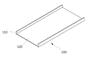
도 1은 본 발명의 메탈프레임의 가공을 위하여 H형 단면을 갖도록 알루미늄 빌렛을 길게 압출성형 한 일 실시 예.
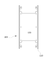
도 2는 본 발명의 H형 단면을 갖도록 길게 압출성형 된 것을 일정한 길이로 절단하는 일 실시 예.
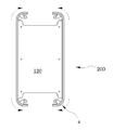
도 3은 본 발명의 노칭가공에 의하여 메탈프레임을 가공하는 일 실시 예.
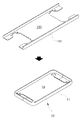
도 4는 본 발명의 노칭가공된 메탈프레임의 모서리부분을 절곡한 일 실시 예
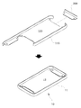
도 5는 본 발명의 모서리가 절곡된 메탈프레임의 전후 양단에 개구되어진 부분에 덧대어지는 조각메탈프레임의 가공된 상태의 일 실시 예.
도 6은 본 발명의 조각메탈프레임이 메탈프레임의 전후양단에 덧대여진 상태의 일 실시 예.
도 7 및 도8은 본 발명의 노칭가공된 메탈프레임의 모서리부분을 절곡하여 조각메탈프레임을 사용치 아니한 일 실시 예
도9 및 도10은 본 발명의 노칭가공된 메탈프레임의 일단에만 모서리부분을 절곡하여 조각메탈프레임을 사용한 일 실시 예
도11은 본 발명의 조각메탈프레임이 메탈프레임의 전후양단에 덧대여진 상태에서 인서트 사출성형된 일 실시 예.
도12는 본 발명의 인서트사출성형에 의하여 메탈케이스로 완성된 제품상태의 일 실시 예.
도13의 a,b는 도1의 알루미늄 빌렛을 또 다른 단면의 형태로 압출성형되는 또 다른 일 실시 예.
도14의 a 내지 d는 본 발명의 알루미늄 빌렛을 압출성형할 경우에 좌우 외벽의 형상을 다양하게 가공가능한 상태를 도시한 일 실시 예.
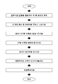
도15는 본 발명의 제조 공정의 일 실시 예의 블럭도
도16a 내지 도16d는 본 발명의 밧데리 일체형에 적용가능한 또 다른 가공상태의 공정과정을 도시한 일 실시 예FIG. 1 shows an embodiment in which an aluminum billet is extruded so as to have an H-shaped cross section for machining a metal frame of the present invention.
Fig. 2 is an embodiment in which a long extrusion molded article having an H-shaped cross section according to the present invention is cut into a predetermined length.
Fig. 3 is an embodiment for machining a metal frame by the notching process of the present invention. Fig.
FIG. 4 is a cross-sectional view of a metal frame according to an embodiment of the present invention,
5 is an exploded perspective view of a metal frame according to an embodiment of the present invention;
6 is an embodiment in which the sculptural metal frame of the present invention is padded at both ends of the metal frame.
FIGS. 7 and 8 are cross-sectional views illustrating an embodiment in which the edges of the notch-processed metal frame of the present invention are bent so that the metal frame is not used
9 and 10 show an embodiment using a sculptural metal frame by bending an edge only at one end of the notched metal frame of the present invention
11 is an embodiment in which the sculptural metal frame of the present invention is insert injection molded in a state where it is padded at both ends of a metal frame.
12 is an embodiment of a product state completed with a metal case by insert injection molding of the present invention.
Figs. 13 (a) and 13 (b) show another embodiment in which the aluminum billet of Fig. 1 is extruded in the form of another cross section.
Figs. 14 (a) to 14 (d) are views showing a state in which the shape of the left and right outer walls can be variously machined when the aluminum billet of the present invention is extrusion-molded.
15 is a block diagram of an embodiment of the manufacturing process of the present invention
FIGS. 16A to 16D are views showing another embodiment of a processing process in a processing state applicable to the battery integrated type of the present invention
이하 첨부도면에 의거 본 발명의 일 실시 예에 의거 상세히 설명하면 다음과 같다.DETAILED DESCRIPTION OF THE PREFERRED EMBODIMENTS Hereinafter, an embodiment of the present invention will be described in detail with reference to the accompanying drawings.
우선 본 발명은 도1에 도시된 바와 같이 알루미늄 빌렛(Billet)을 압출시켜 단면이 H"형상으로 이루어지는 압출프레임(100)을 제작하는 가공 준비단계이다.First, the present invention is a processing preparation step for manufacturing an
본 발명에서는 가공 준비단계에서 압출프레임(100)의 단면이 H형상으로 설명되고 있으나 도13a,b에 도시된 바와 같은 단면을 갖는 것일 경우에도 동일한 방법으로 제조가 가능토록 할 수 있는 것이다. In the present invention, the cross-section of the
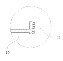
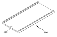
그후 도2에 도시된 바와 같이 가공 준비단계에서 "H"자로 압출된 압출프레임(100)을 최종가공단계에서 얻어지는 메탈케이스(10)의 전개장을 감안하여 사전에 설정된 일정 길이로 절단하는 제1단계이다.Then, as shown in Fig. 2, the
이때 일정길이로 절단된 상태에서는 좌우 외벽(110)과 그 내측으로 중간판(120)을 구비토록 하는 것이고, 상기 좌우 외벽(110)은 도7 내지 도12에 도시된 바와 같이 메탈케이스(10)로 가공된 상태에서 테두리면(11)을 형성하는 것이고, 중간판(120)은 베이스 판(12)을 형성하게 되는 것이다.7 to 12, the left and right
이런 상태에서 도3에 도시된 바와 같이 중간판(120)의 잉여부분(b)을 프레스 전단가공의 일종인 노칭(Notching)가공하여 메탈프레임(200)으로의 가공을 위하여 중간판(120)에서 불필요한 부분의 일부를 제거하는 제2단계이다.3, the surplus portion b of the
이때 중간판(120)의 불필요한 부분의 제거는 도4에 도시된 바와 같이 제3단계에서 좌우 외벽(110)의 양단을 절곡가능하기 위한 범위내에서 이루어지게 되는 것이다.At this time, the removal of unnecessary portions of the
도4는 상기 제2단계에서 노칭가공되어 중간판(120)에서 불필요한 부분을 제거한 상태에서 좌우 외벽(110)의 양단을 절곡가공 하는 제3단계이다.4 is a third step of bending both ends of the left and right
이때 노칭가공된 메탈프레임(200)의 좌우 외벽(110)의 양단을 절곡 가공하기 위하여 본 발명에서는 지그(도시생략)를 사용하여 도3에 도시된 바와 같이 노칭가공된 상태에서 잉여부분(b)이 제거되어 개구되어지는 전후 양단의 좌우 외벽(110)의 모서리부를 절곡하여 가공된 상태에서의 모서리가 둥근 형태(α)로 메탈프레임(200)을 유지시키는 것이다.At this time, in order to bend both ends of the left and right
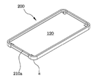
상기 제3단계에서 중간판(120)에서 불필요한 부분을 제거한 상태에서 좌우 외벽(110)의 양단을 절곡가공하여 메탈프레임(200) 형상으로 가공된 상태에서 도5에 도시된 바와 같이 전후 양단의 개구되어진 부분(210)에 연결될 수 있도록 조각메탈프레임(300)의 형상을 가공하는 제4단계이다.5, in a state where both ends of the left and right
*이때 조각메탈프레임(300)을 가공하기 위하여 NC가공에 의한 방법과 알루미늄 빌렛을 압출성형하여 가공하는 방법 또는 프레스 가공방법으로 불 필요한 길이의 절단 및 원하는 형상으로 가공하게 되는 것이다.At this time, in order to process the
그러나 이러한 가공을 위한 어떠한 방법도 본 발명의 목적을 제한하는 것이 아님을 명심해야 한다.It should be borne in mind, however, that no method for such processing is intended to limit the scope of the present invention.
도6은 상기 제4단계에서 조각 메탈프레임(300)으로 가공된 것을, 도11,12에 도시된 바와 같이 인서트 사출에 의하여 메탈케이스를 구성하기 위하여, 메탈프레임(200)의 전후 양단에 개구되어진 부분(210)에 덧대어질 수 있도록 사출금형에 각각 인서트 하여 인서트 사출공법을 이용하여 메탈케이스(10)로 성형하기 위하여 인서트 사출성형하는 제5단계이다.6 is a cross-sectional view of a
그후 도11 및 도12에 도시된 바와 같이 인서트 사출성형된 메탈케이스(10)에 사출성형시 발생되는 잉여부분의 제거와 필요시 설계구조에 따라 NC 가공하는 제6단계이다.Then, as shown in FIGS. 11 and 12, in the sixth step of removing the surplus portion generated in the injection molding of the
그후 제6단계에서 완성되어진 메탈케이스(10) 표면에 다양한 색상을 구현하기 위하여 표면처리를 하는 제7단계로 이루어지는 것이다.And a seventh step of performing surface treatment to realize various colors on the surface of the
한편 도9 및 도10은 제5단계에서 인서트 사출성형의 용이성를 위하여 제4단계에서 가공되어지는 조각메탈프레임을 1개만을 가공하여 사용한 또 다른 일 실시 예를 도시한 것이고, 9 and 10 illustrate another embodiment in which only one piece of the metal frame to be processed in the fourth step is machined for ease of insert injection molding in the fifth step,
이럴 경우에는 본 발명의 가공준비단계에서 제1단계 내지 제7단계의 공정이 동일하게 적용되어지는 것이다.In this case, the processes of the first to seventh steps are equally applied in the processing preparation step of the present invention.
그러나 도7 및 도8은 조각메탈프레임을 사용치 아니한 것을 도시한 것으로 도4단계에서 이루어지는 조각메탈프레임의 가공이 불필요함으로 본 발명의 공정중에서 제4단계의 공정이 불필요한 것이고 제3단계에서 중간판(120)에서 불필요한 부분을 제거한 상태에서 좌우 외벽(110)의 양단을 절곡가공하여 메탈프레임(200) 형상으로 가공한 상태에서 개구부가 없이 가공하는 제3a단계로 이루어지는 것이고 그 상태에서 제4단계가 없이 제5단계로 연결되어지는 것이다.However, FIGS. 7 and 8 illustrate that the metal frame is not used, and the process of the fourth step is unnecessary in the process of the present invention because the machining of the metal frame of FIG. 4 is unnecessary. In the third step, (B) bending both ends of the left and right
본 발명에서 기술되어진 가공 준비단계에서 단면 형상이 H" 자인 프레임을 압출성형하는 것은 좌우 외벽(110)은 최종단계에서 얻어진 메탈케이스(10)의 외곽의 테두리면(11)을 구성하게 되는 것이고, 중간판(120)의 어느 일면은 윈도우글라스 및 전자부품이 조립된 기판의 안착 및 고정이 타측면으로는 밧데리의 실장을 위한 공간으로 사용할 수 있는 베이스 보드(12)를 구성하게 되는 것이다.In the machining preparation step described in the present invention, the H "-shaped frame is extruded so that the left and right
또한 본 발명에서 조각메탈프레임(300)을 가공하기 위하여는 가공준비단계에서 압출되어지는 단면 H형 압출프레임을 등분하여 좌우 외벽을 T"자의 단면형상으로 NC가공토록 함으로서 인서트 사출성형된 상태에서 테두리면(11)을 동일한 규격의 재질유지가 가능토록 한 것이다.In order to process the
본 발명에서 도시된 도13의 a는 밧데리가 외장형일 경우에 사용될 수 있는 형태이고 도13b는 밧데리의 내장형 또는 외장형에 모두 사용가능할 수 있는 것이고, 본 발명은 밧데리 내장형 또는 외장형의 형태로 설명되고 있는 것이다.13a of the present invention can be used when the battery is of an external type, and FIG. 13b can be used both of the internal or external type of the battery, and the present invention is described in the form of a battery built-in type or an external type will be.
그러나 이러한 밧데리의 내장형이나 외장형이 본 발명의 목적을 제한하는 것이 아님을 명심해야 할 것이다.It should be borne in mind, however, that the built-in or external form of such a battery does not limit the object of the present invention.
또한 도14의 a 내지 d는 본 발명의 가공준비단계에서 얻어지는 압출프레임(100)의 압출성형시에 가공 준비단계와 제1단계 내지 제7단계를 거쳐 얻어지는 최종결과문인 메탈케이스(10)의 테두리면(11)의 노출된 형상의 다양한 일 실시 예를 도시한 것으로 알루미늄의 빌렛을 압출성형할 경우에 다양한 형태로의 압출이 가능하게 되어 가공의 용이성에 다양한 디자인성을 얻을 수 있게 되는 장점이 있는 것이다. Figs. 14 (a) to 14 (d) are diagrams showing the results of the extrusion molding of the
도16a 내지 도16d는 본 발명의 또 다른 일 실시 예를 도시한 것으로, 도16a에 도시된 바와 같이 알루미늄 빌렛(Billet)을 압출시켜 단면이 H"형상인 압출프레임(100)을 제작하는 가공 준비단계와 상기 가공 준비단계에서 "H"자 프레임으로 압출된 것을 압출프레임(100)을 최종가공단계에서 얻어지는 메탈케이스(10)의 전개장을 감안하여 좌우외벽과 중간판이 형성되게 사전에 설정된 길이로 절단하는 제1단계와 상기 중간판(120)의 잉여부분을 프레스 전단가공의 일종인 노칭(Notching)가공하여 메탈프레임(200)으로의 가공을 위하여 중간판(120)에서 불필요한 부분의 일부를 제거하는 제2단계와 상기 제2단계에서 노칭가공되어 중간판(120)에서 불필요한 부분을 제거한 상태에서 좌우 외벽(110)의 양단을 절곡가공 하는 제3단계와 상기 제3단계에서 좌우 외벽(110)의 양단을 절곡가공하여 메탈프레임(200) 형상으로 가공된 상태에서 전후 양단에 노출되는 중간판을 절곡하여 직립벽(210a)을 형성하는 제4단계와 상기 제4단계에서 필요시 직립벽(210a)에 사출금형에 인서트 하여 인서트 사출공법을 이용하여 메탈케이스(10)로 성형하기 위하여 인서트 사출성형하는 제5단계로 가공되어지는 것이다.16A to 16D illustrate another embodiment of the present invention. As shown in FIG. 16A, an aluminum billet is extruded to prepare an
본 발명에서는 가공준비단계에서 H형 압출프레임으로 설명되고 있으나 이에 국한 되는 것이 아니고, 밧데리 내장형이나 외장형이냐에 따라 ![]()
![]()
α:둥근형태 b:잉여부분
10:메탈케이스 11:테두리면
12:베이스 보드
100:압출프레임 110:좌우외벽
120:중간판
200:메탈프레임 210:개구되어진 부분
210a:직립벽
300:조각메탈프레임α: round shape b: surplus portion
10: metal case 11:
12: Baseboard
100: extrusion frame 110: left and right outer walls
120: intermediate plate
200: metal frame 210: open part
210a: upright wall
300: Sculptured metal frame
Claims (9)
가공 준비단계에서 "H"자 프레임으로 압출된 것을 압출프레임(100)을 최종가공단계에서 얻어지는 메탈케이스(10)의 전개장을 감안하여 좌우외벽과 중간판이 형성되게 사전에 설정된 길이로 절단하는 제1단계
상기 중간판(120)의 잉여부분을 프레스 전단가공의 일종인 노칭(Notching)가공하여 메탈프레임(200)으로의 가공을 위하여 중간판(120)에서 불필요한 부분의 일부를 제거하는 제2단계.
상기 제2단계에서 노칭가공되어 중간판(120)에서 불필요한 부분을 제거한 상태에서 좌우 외벽(110)의 양단을 절곡가공 하는 제3단계.
상기 제3단계에서 중간판(120)에서 불필요한 부분을 제거한 상태에서 좌우 외벽(110)의 양단을 절곡가공하여 메탈프레임(200) 형상으로 가공된 상태에서 전후 양단의 개구되어진 부분(210)에 연결될 수 있도록 조각메탈프레임(300)의 형상을 가공하는 제4단계.
상기 제4단계에서 조각 메탈프레임(300)으로 가공된 것을, 메탈케이스를 구성하기 위하여, 메탈프레임(200)과 메탈프레임의 전후 양단에 개구되어진 부분(210)에 덧대어질 수 있도록 사출금형에 각각 인서트 하여 인서트 사출공법을 이용하여 메탈케이스(10)로 성형하기 위하여 인서트 사출성형하는 제5단계로 가공되어지는 단면 H형의 압출에 의한 휴대폰용 메탈케이스의 제조방법An aluminum billet is extruded to prepare an extrusion frame 100 having an H "
The extrusion frame 100 is extruded by the "H" frame in the preparation preparation step, and the extrusion frame 100 is cut in a predetermined length so as to form the left and right outer walls and the intermediate plate in consideration of the development length of the metal case 10, Stage 1
A second step of notching a surplus portion of the intermediate plate 120 to form a part of the unnecessary portion in the intermediate plate 120 for machining into the metal frame 200.
A third step of bending both ends of the left and right outer walls 110 in a state where the unnecessary portions are removed from the intermediate plate 120 by notching in the second step.
In the third step, both ends of the left and right outer walls 110 are bent and connected to the opened portions 210 at both ends of the front and back in a state of being processed into the shape of the metal frame 200 with the unnecessary portions removed from the intermediate plate 120 A fourth step of processing the shape of the sculptural metal frame 300 so that the sculptural metal frame 300 is formed.
In order to construct the metal case, the metal frame 200 is processed into the metal frame 300 in the fourth step so that the metal frame 200 and the metal frame are inserted into the openings 210 at both ends of the metal frame. A method of manufacturing a metal case for a mobile phone by extrusion of an H-shaped section to be processed in a fifth step of insert injection molding to insert into a metal case 10 using an insert injection method
상기 인서트 사출성형된 메탈케이스(10)에 사출성형시 발생되는 잉여부분의 제거와 필요시 설계구조에 따라 NC 가공하는 제6단계가 추가되어지는 단면 H형의 압출에 의한 휴대폰용 메탈케이스의 제조방법The method of claim 1, wherein
A metal case for a mobile phone is manufactured by extrusion of a section H shape in which a surplus portion generated during injection molding is removed from the insert injection molded metal case 10 and a sixth step of NC processing is added according to the design structure, Way
상기 제6단계에서 완성되어진 메탈케이스(10) 표면에 다양한 색상을 구현하기 위하여 표면처리를 하는 제7단계가 추가되어지는 단면 H형의 압출에 의한 휴대폰용 메탈케이스의 제조방법The method according to claim 2, wherein
A method for manufacturing a metal case for a mobile phone by extrusion of an H-shaped cross section in which a seventh step of performing surface treatment to implement various colors on the surface of the metal case 10 completed in the sixth step is added
상기 가공 준비단계에서 압출프레임(100)의 단면이 H형상은 단면이
In the process preparation step, the cross section of the extrusion frame 100 has a cross section of H
상기 노칭가공된 메탈프레임(200)을 가공하기 위하여 지그(도시생략)를 사용하여 노칭가공된 상태에서 개구되어지는 전후 양단의 좌우 외벽(110)의 모서리부를 절곡하여 둥근 형태(α)로 가공하여 메탈프레임(200)을 유지토록 하는 단면 H형의 압출에 의한 휴대폰용 메탈케이스의 제조방법The method of claim 1, wherein
In order to process the notch-processed metal frame 200, the edges of the left and right outer walls 110 at both ends of the front and rear ends, which are opened in a notched state using a jig (not shown), are bent and processed into a round shape A method for manufacturing a metal casing for a mobile phone by extrusion of an H-shaped cross section for holding the metal frame (200)
상기 인서트사출성형시 가공되어진 조각메탈프레임을 사출금형에 삽입하여 플라스틱으로 사출성형함으로 분리된 조각 메탈프레임을 결합시키는 것과 내측면에 플라스틱을 사출성형시킴으로 사각형메탈케이스를 형성시키는 단면 H형의 압출에 의한 휴대폰용 메탈케이스의 제조방법The method according to claim 1,
In the insert injection molding, the cut metal frame is inserted into an injection mold, injection molded into plastic to join the separated metal frame, and injection molding of plastic on the inner side to form a rectangular metal case. For manufacturing a metal case for a mobile phone
상기 조각메탈프레임은 단면H형 압출프레임을 3등분 분리하여 메탈케이스 상하프레임으로 사용하기 위하여 단면형상을 T"자로 NC가공하는 단면 H형의 압출에 의한 휴대폰용 메탈케이스의 제조방법The method of claim 1, wherein
The above-mentioned scraped metal frame is NC-processed into a T-shaped cross-section so as to be used as a metal case upper and lower frame by dividing the H-shaped extrusion frame into three sections, and a method for manufacturing a metal case for a mobile phone by extrusion of a H-
상기 메탈케이스의 테두리면의 노출된 다양한 형상은 알루미늄의 빌렛을 압출성형할 경우에 동시에 압출되어지는 단면 H형의 압출에 의한 휴대폰용 메탈케이스의 제조방법The method according to claim 1,
The various exposed shapes of the rim surface of the metal case include a method of manufacturing a metal case for a mobile phone by extrusion of a cross-section H shape, which is simultaneously extruded when the billet of aluminum is extruded
가공 준비단계에서 "H"자 프레임으로 압출된 것을 압출프레임(100)을 최종가공단계에서 얻어지는 메탈케이스(10)의 전개장을 감안하여 좌우외벽과 중간판이 형성되게 사전에 설정된 길이로 절단하는 제1단계
상기 중간판(120)의 잉여부분을 프레스 전단가공의 일종인 노칭(Notching)가공하여 메탈프레임(200)으로의 가공을 위하여 중간판(120)에서 불필요한 부분의 일부를 제거하는 제2단계.
상기 제2단계에서 노칭가공되어 중간판(120)에서 불필요한 부분을 제거한 상태에서 좌우 외벽(110)의 양단을 절곡가공 하여 개구부가 없이 메탈프레임(200) 형상으로 가공을 위한 제3a단계로 이루어진다.
그후 상기 제3a단계에서 메탈프레임(200)을 사출금형에 인서트 하여 인서트 사출공법을 이용하여 메탈케이스(10)로 성형하기 위하여 인서트 사출성형하는 제5단계로 가공되어지는 단면 H형의 압출에 의한 휴대폰용 메탈케이스의 제조방법
An aluminum billet is extruded to prepare an extrusion frame 100 having an H "
The extrusion frame 100 is extruded by the "H" frame in the preparation preparation step, and the extrusion frame 100 is cut in a predetermined length so as to form the left and right outer walls and the intermediate plate in consideration of the development length of the metal case 10, Stage 1
A second step of notching a surplus portion of the intermediate plate 120 to form a part of the unnecessary portion in the intermediate plate 120 for machining into the metal frame 200.
Step 3a for bending both ends of the left and right outer walls 110 in a state where the unnecessary portions are removed from the intermediate plate 120 by notching in the second step and machining the metal frame 200 without an opening.
Thereafter, in step 3a, the metal frame 200 is inserted into an injection mold and subjected to an insert injection molding process for molding into a metal case 10 using an insert injection molding method. Manufacturing method of metal case for mobile phone
Priority Applications (1)
| Application Number | Priority Date | Filing Date | Title |
|---|---|---|---|
| KR1020160031041A KR102407180B1 (en) | 2015-12-16 | 2016-03-15 | Manufacture process for metal case of mobile phone |
Applications Claiming Priority (2)
| Application Number | Priority Date | Filing Date | Title |
|---|---|---|---|
| KR1020150180147A KR101618098B1 (en) | 2015-12-16 | 2015-12-16 | Manufacture process for metal case of mobile phone |
| KR1020160031041A KR102407180B1 (en) | 2015-12-16 | 2016-03-15 | Manufacture process for metal case of mobile phone |
Related Parent Applications (1)
| Application Number | Title | Priority Date | Filing Date |
|---|---|---|---|
| KR1020150180147A Division KR101618098B1 (en) | 2015-12-16 | 2015-12-16 | Manufacture process for metal case of mobile phone |
Publications (2)
| Publication Number | Publication Date |
|---|---|
| KR20170072103A true KR20170072103A (en) | 2017-06-26 |
| KR102407180B1 KR102407180B1 (en) | 2022-06-10 |
Family
ID=81986295
Family Applications (1)
| Application Number | Title | Priority Date | Filing Date |
|---|---|---|---|
| KR1020160031041A KR102407180B1 (en) | 2015-12-16 | 2016-03-15 | Manufacture process for metal case of mobile phone |
Country Status (1)
| Country | Link |
|---|---|
| KR (1) | KR102407180B1 (en) |
Cited By (3)
| Publication number | Priority date | Publication date | Assignee | Title |
|---|---|---|---|---|
| WO2019022559A1 (en) * | 2017-07-27 | 2019-01-31 | (주)케이에이치바텍 | Method for manufacturing frame structure for portable terminal |
| KR101966949B1 (en) * | 2017-11-15 | 2019-04-09 | (주)티에스이 | The method for fabricating smart phone cover |
| KR101981537B1 (en) * | 2017-11-23 | 2019-08-28 | 엘지전자 주식회사 | Mobile terminal including metal case and method of manufacturing metal case |
Citations (3)
| Publication number | Priority date | Publication date | Assignee | Title |
|---|---|---|---|---|
| KR20050098632A (en) * | 2004-04-08 | 2005-10-12 | 안계훈 | Manufacturing process for an oil-pressure case |
| KR101390973B1 (en) * | 2013-09-11 | 2014-05-07 | 주식회사 파인테크닉스 | A method of manufacturing metal-deco-frame for portable electronic device |
| KR101453067B1 (en) * | 2014-07-23 | 2014-10-27 | 신성전자정밀 주식회사 | Manufacture process for metal case of mobile phone |
-
2016
- 2016-03-15 KR KR1020160031041A patent/KR102407180B1/en active IP Right Grant
Patent Citations (3)
| Publication number | Priority date | Publication date | Assignee | Title |
|---|---|---|---|---|
| KR20050098632A (en) * | 2004-04-08 | 2005-10-12 | 안계훈 | Manufacturing process for an oil-pressure case |
| KR101390973B1 (en) * | 2013-09-11 | 2014-05-07 | 주식회사 파인테크닉스 | A method of manufacturing metal-deco-frame for portable electronic device |
| KR101453067B1 (en) * | 2014-07-23 | 2014-10-27 | 신성전자정밀 주식회사 | Manufacture process for metal case of mobile phone |
Cited By (3)
| Publication number | Priority date | Publication date | Assignee | Title |
|---|---|---|---|---|
| WO2019022559A1 (en) * | 2017-07-27 | 2019-01-31 | (주)케이에이치바텍 | Method for manufacturing frame structure for portable terminal |
| KR101966949B1 (en) * | 2017-11-15 | 2019-04-09 | (주)티에스이 | The method for fabricating smart phone cover |
| KR101981537B1 (en) * | 2017-11-23 | 2019-08-28 | 엘지전자 주식회사 | Mobile terminal including metal case and method of manufacturing metal case |
Also Published As
| Publication number | Publication date |
|---|---|
| KR102407180B1 (en) | 2022-06-10 |
Similar Documents
| Publication | Publication Date | Title |
|---|---|---|
| KR101618098B1 (en) | Manufacture process for metal case of mobile phone | |
| KR101590181B1 (en) | A billet of an aluminum metal produced by the extrusion method phone case and a method of manufacturing the same | |
| JP5760127B2 (en) | Electronic device housing and method of manufacturing the same | |
| KR20170072103A (en) | Manufacture process for metal case of mobile phone | |
| CN109759780B (en) | Method for preparing middle frame, middle frame and mobile terminal | |
| KR101717469B1 (en) | Manufacturing Method For Metal Frame of Mobile Phone | |
| US20170078460A1 (en) | Frame for mobile communication terminal and method of manufacturing the same | |
| CN106163165A (en) | Electronic installation and preparation method thereof | |
| CN107683040B (en) | Shell manufacturing method, shell and mobile terminal | |
| CA2520322A1 (en) | Integral frame member for an aircraft | |
| CN105345987A (en) | Manufacturing method of mobile phone middle frame and mobile phone middle frame | |
| CN105282279A (en) | Framework structure manufacture method of portable terminal apparatus | |
| KR20160108102A (en) | A metal basecase of mobile | |
| KR101558550B1 (en) | A metal-base- board of mobile that is processed by the press, its manufacture method | |
| JP2012017135A (en) | Case and its manufacturing method | |
| KR102050588B1 (en) | Manufacturing method of mobile phone metal case formed by banding and process using cam cype mold | |
| KR101569924B1 (en) | A manufacture method of metal case for mobile | |
| JPH10323858A (en) | Manufacture of plastic outer shell and bezel | |
| CN110612715A (en) | Method for manufacturing frame structure for portable terminal | |
| JP3951243B2 (en) | Window manufacturing method in in-mold molding | |
| CN109128693A (en) | The manufacturing method of fastener with full figure pattern | |
| US20070069431A1 (en) | Method of manufacturing a bumper cover for a motor vehicle | |
| CN216683141U (en) | Die structure of frame-shaped product with front inclined hole and rear inclined hole | |
| KR20120000344A (en) | Case for an electronic device and manufacturing method thereof | |
| KR20090097037A (en) | Film insert moulded material and the method for manufacturing of the same |
Legal Events
| Date | Code | Title | Description |
|---|---|---|---|
| A107 | Divisional application of patent | ||
| A201 | Request for examination | ||
| E902 | Notification of reason for refusal | ||
| E701 | Decision to grant or registration of patent right |