KR20170066336A - Log scanning system - Google Patents
Log scanning system Download PDFInfo
- Publication number
- KR20170066336A KR20170066336A KR1020177006821A KR20177006821A KR20170066336A KR 20170066336 A KR20170066336 A KR 20170066336A KR 1020177006821 A KR1020177006821 A KR 1020177006821A KR 20177006821 A KR20177006821 A KR 20177006821A KR 20170066336 A KR20170066336 A KR 20170066336A
- Authority
- KR
- South Korea
- Prior art keywords
- log
- data
- load
- depth
- texture
- Prior art date
Links
Images


Classifications
-
- G—PHYSICS
- G06—COMPUTING; CALCULATING OR COUNTING
- G06K—GRAPHICAL DATA READING; PRESENTATION OF DATA; RECORD CARRIERS; HANDLING RECORD CARRIERS
- G06K7/00—Methods or arrangements for sensing record carriers, e.g. for reading patterns
- G06K7/10—Methods or arrangements for sensing record carriers, e.g. for reading patterns by electromagnetic radiation, e.g. optical sensing; by corpuscular radiation
- G06K7/10544—Methods or arrangements for sensing record carriers, e.g. for reading patterns by electromagnetic radiation, e.g. optical sensing; by corpuscular radiation by scanning of the records by radiation in the optical part of the electromagnetic spectrum
- G06K7/10712—Fixed beam scanning
- G06K7/10722—Photodetector array or CCD scanning
-
- B—PERFORMING OPERATIONS; TRANSPORTING
- B07—SEPARATING SOLIDS FROM SOLIDS; SORTING
- B07C—POSTAL SORTING; SORTING INDIVIDUAL ARTICLES, OR BULK MATERIAL FIT TO BE SORTED PIECE-MEAL, e.g. BY PICKING
- B07C5/00—Sorting according to a characteristic or feature of the articles or material being sorted, e.g. by control effected by devices which detect or measure such characteristic or feature; Sorting by manually actuated devices, e.g. switches
- B07C5/04—Sorting according to size
- B07C5/12—Sorting according to size characterised by the application to particular articles, not otherwise provided for
- B07C5/14—Sorting timber or logs, e.g. tree trunks, beams, planks or the like
-
- G—PHYSICS
- G01—MEASURING; TESTING
- G01B—MEASURING LENGTH, THICKNESS OR SIMILAR LINEAR DIMENSIONS; MEASURING ANGLES; MEASURING AREAS; MEASURING IRREGULARITIES OF SURFACES OR CONTOURS
- G01B11/00—Measuring arrangements characterised by the use of optical techniques
- G01B11/24—Measuring arrangements characterised by the use of optical techniques for measuring contours or curvatures
- G01B11/25—Measuring arrangements characterised by the use of optical techniques for measuring contours or curvatures by projecting a pattern, e.g. one or more lines, moiré fringes on the object
-
- G—PHYSICS
- G01—MEASURING; TESTING
- G01N—INVESTIGATING OR ANALYSING MATERIALS BY DETERMINING THEIR CHEMICAL OR PHYSICAL PROPERTIES
- G01N21/00—Investigating or analysing materials by the use of optical means, i.e. using sub-millimetre waves, infrared, visible or ultraviolet light
- G01N21/84—Systems specially adapted for particular applications
- G01N21/88—Investigating the presence of flaws or contamination
-
- G—PHYSICS
- G06—COMPUTING; CALCULATING OR COUNTING
- G06F—ELECTRIC DIGITAL DATA PROCESSING
- G06F17/00—Digital computing or data processing equipment or methods, specially adapted for specific functions
-
- G—PHYSICS
- G06—COMPUTING; CALCULATING OR COUNTING
- G06K—GRAPHICAL DATA READING; PRESENTATION OF DATA; RECORD CARRIERS; HANDLING RECORD CARRIERS
- G06K17/00—Methods or arrangements for effecting co-operative working between equipments covered by two or more of main groups G06K1/00 - G06K15/00, e.g. automatic card files incorporating conveying and reading operations
- G06K17/0022—Methods or arrangements for effecting co-operative working between equipments covered by two or more of main groups G06K1/00 - G06K15/00, e.g. automatic card files incorporating conveying and reading operations arrangements or provisious for transferring data to distant stations, e.g. from a sensing device
-
- G—PHYSICS
- G06—COMPUTING; CALCULATING OR COUNTING
- G06K—GRAPHICAL DATA READING; PRESENTATION OF DATA; RECORD CARRIERS; HANDLING RECORD CARRIERS
- G06K7/00—Methods or arrangements for sensing record carriers, e.g. for reading patterns
- G06K7/10—Methods or arrangements for sensing record carriers, e.g. for reading patterns by electromagnetic radiation, e.g. optical sensing; by corpuscular radiation
- G06K7/12—Methods or arrangements for sensing record carriers, e.g. for reading patterns by electromagnetic radiation, e.g. optical sensing; by corpuscular radiation using a selected wavelength, e.g. to sense red marks and ignore blue marks
-
- G—PHYSICS
- G06—COMPUTING; CALCULATING OR COUNTING
- G06K—GRAPHICAL DATA READING; PRESENTATION OF DATA; RECORD CARRIERS; HANDLING RECORD CARRIERS
- G06K7/00—Methods or arrangements for sensing record carriers, e.g. for reading patterns
- G06K7/10—Methods or arrangements for sensing record carriers, e.g. for reading patterns by electromagnetic radiation, e.g. optical sensing; by corpuscular radiation
- G06K7/14—Methods or arrangements for sensing record carriers, e.g. for reading patterns by electromagnetic radiation, e.g. optical sensing; by corpuscular radiation using light without selection of wavelength, e.g. sensing reflected white light
- G06K7/1404—Methods for optical code recognition
- G06K7/1408—Methods for optical code recognition the method being specifically adapted for the type of code
- G06K7/1417—2D bar codes
-
- G—PHYSICS
- G06—COMPUTING; CALCULATING OR COUNTING
- G06Q—INFORMATION AND COMMUNICATION TECHNOLOGY [ICT] SPECIALLY ADAPTED FOR ADMINISTRATIVE, COMMERCIAL, FINANCIAL, MANAGERIAL OR SUPERVISORY PURPOSES; SYSTEMS OR METHODS SPECIALLY ADAPTED FOR ADMINISTRATIVE, COMMERCIAL, FINANCIAL, MANAGERIAL OR SUPERVISORY PURPOSES, NOT OTHERWISE PROVIDED FOR
- G06Q10/00—Administration; Management
- G06Q10/08—Logistics, e.g. warehousing, loading or distribution; Inventory or stock management
- G06Q10/087—Inventory or stock management, e.g. order filling, procurement or balancing against orders
- G06Q10/0875—Itemisation or classification of parts, supplies or services, e.g. bill of materials
-
- G—PHYSICS
- G06—COMPUTING; CALCULATING OR COUNTING
- G06T—IMAGE DATA PROCESSING OR GENERATION, IN GENERAL
- G06T7/00—Image analysis
- G06T7/10—Segmentation; Edge detection
- G06T7/12—Edge-based segmentation
-
- G—PHYSICS
- G06—COMPUTING; CALCULATING OR COUNTING
- G06K—GRAPHICAL DATA READING; PRESENTATION OF DATA; RECORD CARRIERS; HANDLING RECORD CARRIERS
- G06K7/00—Methods or arrangements for sensing record carriers, e.g. for reading patterns
- G06K7/10—Methods or arrangements for sensing record carriers, e.g. for reading patterns by electromagnetic radiation, e.g. optical sensing; by corpuscular radiation
- G06K2007/10524—Hand-held scanners
-
- G—PHYSICS
- G06—COMPUTING; CALCULATING OR COUNTING
- G06T—IMAGE DATA PROCESSING OR GENERATION, IN GENERAL
- G06T2207/00—Indexing scheme for image analysis or image enhancement
- G06T2207/10—Image acquisition modality
- G06T2207/10028—Range image; Depth image; 3D point clouds
-
- G—PHYSICS
- G06—COMPUTING; CALCULATING OR COUNTING
- G06T—IMAGE DATA PROCESSING OR GENERATION, IN GENERAL
- G06T2207/00—Indexing scheme for image analysis or image enhancement
- G06T2207/30—Subject of image; Context of image processing
- G06T2207/30108—Industrial image inspection
- G06T2207/30161—Wood; Lumber
-
- G—PHYSICS
- G06—COMPUTING; CALCULATING OR COUNTING
- G06T—IMAGE DATA PROCESSING OR GENERATION, IN GENERAL
- G06T2207/00—Indexing scheme for image analysis or image enhancement
- G06T2207/30—Subject of image; Context of image processing
- G06T2207/30242—Counting objects in image
Abstract
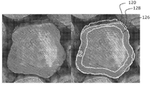
로그 스캔 시스템 및 로그 로드를 스캔하는 방법에 관한 것이다. 로그 로드의 각각의 개별적인 로그는 적어도 하나의 로그 엔드 페이스 상에 고유한 로그 ID 데이터를 갖는 ID 요소를 가질 수 있다. 시스템은, 로그 로드의 로드 엔드 페이스에 걸친 조작자에 의한 자유 형태 스캔을 위한 핸드헬드 스캐너 유닛을 구비한다. 스캐너 유닛은, 로드 엔드 페이스의 스캔 동안 로드 엔드 페이스의 일련의 깊이 화상들을 캡처하도록 구성된 깊이 센서 및 로드 엔드 페이스의 일련의 텍스처 화상들을 캡처하도록 구성된 텍스처 센서를 구비한다. 시스템은, 또한, 스캔으로부터 캡처되는 깊이 화상들과 텍스처 화상들을 수신하고 처리하는 데이터 프로세서(들)를 구비한다. 프로세서(들)는, 깊이 화상들 또는 깊이 화상들과 텍스처 화상들을 로드 엔드 페이스의 데이터 모델로 융합하고, 데이터 모델을 처리함으로써 로드 엔드 페이스에서 볼 수 있는 개별적인 로그들의 로그 엔드 경계들을 결정하고, 텍스트 화상들을 처리하여 스캔에서 볼 수 있는 임의의 ID 요소들을 식별 및 디코딩하여 개별적인 로그 ID 데이터를 추출하고, 결정된 로그 엔드 경계들과 추출된 로그 ID 데이터에 기초하여 로그 로드를 나타내는 출력 데이터를 생성하도록 구성된다.A log scan system and a method of scanning the log load. Each individual log of the log load may have an ID element with unique log ID data on at least one log endface. The system includes a handheld scanner unit for free form scanning by an operator over a load endface of the log load. The scanner unit includes a depth sensor configured to capture a series of depth images of the rod end face during a scan of the rod end face, and a texture sensor configured to capture a series of texture images of the rod end face. The system also includes a data processor (s) for receiving and processing depth images and texture images captured from the scan. The processor (s) fuses depth images or depth images and texture images into a data model at the load end face, processes the data model to determine the log end boundaries of the individual logs viewable at the load end face, Processing the images to identify and decode any ID elements visible in the scan to extract individual log ID data and generate output data indicative of log load based on the determined log end boundaries and extracted log ID data do.
Description
본 발명은, 산림업에서 사용하기 위한 로그 식별, 측정 및/또는 카운트 시스템에 관한 것이다.The present invention relates to a log identification, measurement and / or counting system for use in forestry.
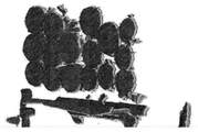
뉴질랜드 및 기타 여러 국가의 로그 수출업계는 수출되는 모든 로그를 카운트하고 바코드 처리해야 한다. 수확 후, 수출용 로그는 통상적으로 벌목 트럭이나 트레일러 상에서 항구까지 전달된다. 각 트럭의 로그들의 로드(load)는, 항구에 도착하면, 검문소 또는 처리소에서 처리된다. 통상적으로, 각 로드의 로그들의 개수가 카운트되며, 각각의 개별적인 로그에 대한 다양한 측정은, 수출용으로 적재되기 전에 볼륨 및 값에 대한 스케일에 따라 수행된다.Log export industry in New Zealand and many other countries should count and barcode all logs exported. After harvesting, export logs are typically delivered to harbors on logging trucks or trailers. The load of the logs of each truck is processed at checkpoints or processing stations when they arrive at the port. Typically, the number of logs for each load is counted, and various measurements for each individual log are performed according to the scale for volume and value before being loaded for export.
국가에 따라서는, 다양한 표준에 따라 로그 스케일링을 수행할 수 있다. 뉴질랜드에서는, 수출되는 거의 모든 로그들이 일본 농업 표준(JAS)에 기초하여 대량 판매된다. JAS 볼륨에 대한 스케일링은, 통상적으로, 각 로그의 작은 엔드 직경과 길이를 측정한 후 이러한 측정값들에 기초하여 JAS 볼륨을 산출하는 것을 포함한다. 로그 카운트와 스케일링 작업은, 현재, 벌목 트럭당 하나 이상의 로그 스케일러를 사용하여 각 로그를 수동으로 카운트하고 스케일링해야 하므로 매우 노동 집약적이다. 로그 카운트와 스케일링 작업은, 숲에서부터 수출용 선박으로 또는 국내 고객에게 공급되는 로그들의 공급 사슬에 병목 현상을 야기할 수 있다.Depending on the country, log scaling may be performed according to various standards. In New Zealand, almost all logs exported are mass-marketed on the basis of the Japanese Agricultural Standards (JAS). Scaling for JAS volumes typically involves measuring the small end diameter and length of each log and then calculating the JAS volume based on these measurements. Log counting and scaling operations are currently very labor intensive because they require manual counting and scaling of each log using more than one log scaler per logging truck. Log counting and scaling operations can cause bottlenecks in the supply chain of logs from forests to export vessels or to domestic customers.
전술한 문제를 해결하고자, 로그의 자동 카운트 및 측정을 보조하기 위한 다양한 자동화 시스템들이 제안되었다. 그러나, 현재 이렇게 제안된 시스템들 상당수에는, 로그 수출 산업에 의한 광범위한 채택이 제한되는 여러 단점들이 있다.In order to solve the above-mentioned problems, various automation systems have been proposed to assist in automatic counting and measurement of logs. However, at present many of these proposed systems have several drawbacks that restrict widespread adoption by the log export industry.
이러한 한 가지 자동화 시스템은 미국 특허출원공개 제2013/0144568호에 개시되어 있다. 이 시스템은 벌목 트럭 상의 로그 로드(log load)를 위한 드라이브-스루(drive-through) 로그 측정 시스템이다. 이 시스템은, 자신의 주변에 레이저들의 어레이를 장착하고 벌목 트럭이 통과할 수도 있는 대형 구조물을 포함한다. 시스템 레이저는, 트럭이 통과할 때 트럭 뒤에 있는 로그 로드를 스캔하여 그 로그 로드의 3D 모델을 생성한다. 이어서, 3D 모델을 처리하여 로그 직경 등의 로그의 다양한 특징들을 추출한다. 이 시스템은 매우 크고 고가이다.One such automated system is disclosed in U.S. Patent Application Publication No. 2013/0144568. The system is a drive-through log measurement system for the log load on logging trucks. The system includes a large structure that mounts an array of lasers around itself and through which a logging truck can pass. The system laser scans the log load behind the truck when the truck passes, creating a 3D model of the log load. The 3D model is then processed to extract various features of the log, such as log diameter. The system is very large and expensive.
로그를 측정하기 위한 또 다른 자동화 시스템은 국제 PCT 특허출원 WO 2005/080949에 개시되어 있다. 이 시스템은, 지상의 로그 더미를 지나 구동되며 로그 더미의 스테레오 비전 화상들을 캡처하는 차량에 장착된 스테레오 비전 측정 유닛을 사용한다. 이어서, 스테레오 화상들을 화상 처리하여, 크기 측정 및 로그 등급화 등의 로그들의 다양한 물리적 특성들을 결정한다. 이 시스템은, 측정 유닛을 지상에 위치한 로그들의 더미를 지나 이동시킬 것을 이동 차량에 요구하며, 벌목 트럭 상의 제 위치에서 로그 로드를 측정하는 데 적합하지 않다.Another automated system for measuring logs is disclosed in International PCT Patent Application WO 2005/080949. The system uses a stereo vision measurement unit mounted on a vehicle that is driven past a log pile on the ground and captures stereo vision images of the log dummy. The stereo images are then image processed to determine various physical characteristics of the logs, such as size measurements and log grading. The system requires the moving vehicle to move the measurement unit past the pile of logs located on the ground and is not suitable for measuring the log load in place on the logging truck.
특허 명세서, 기타 외부 문서, 또는 기타 정보 출처를 인용한 본 명세서에서, 이는 일반적으로 본 발명의 특징을 논의하기 위한 환경을 제공하기 위한 것이다. 특정하게 달리 언급하지 않는 한, 이러한 외부 문서를 인용하는 것이, 임의의 관할권에서의 이러한 문서 또는 이러한 정보 출처가 선행 기술이거나 당업계의 통상적인 지식의 일부를 구성한다는 것을 인정하는 것으로서 해석되어서는 안 된다.Patent specifications, other external documents, or other sources of information, it is generally intended to provide an environment for discussing features of the present invention. Unless specifically stated otherwise, the citation of such external documents should not be construed as an admission that such documents in any jurisdiction or that such sources of information are prior art or constitute part of the ordinary knowledge in the art do.
본 발명의 목적은, 적어도 대중에게 유용한 선택을 제공하도록 또는 로그 더미 또는 로그 로드의 개별적인 로그들을 식별, 측정, 및/또는 카운트하기 위한 시스템 및 방법을 제공하는 것이다.It is an object of the present invention to provide a system and method for identifying, measuring, and / or counting individual logs of log dummies or log loads, at least to provide useful choices to the public.
제1양태에서, 본 발명은 로그들의 로드(로그 로드)를 스캔하기 위한 로그 스캔 시스템으로 주로 이루어지며, 로그 로드의 각각의 개별적인 로그는 적어도 하나의 로그 엔드 페이스(log end face) 상에 고유한 로그 ID 데이터를 포함하는 ID 요소를 포함하며, 이러한 시스템은, 로그 로드의 로드 엔드 페이스에 걸친 조작자에 의한 자유 형태 스캔을 위한 핸드헬드 스캐너 유닛; 및 데이터 프로세서 또는 프로세서들을 포함하고, 핸드헬드 스캐너 유닛은, 로드 엔드 페이스의 스캔 동안 로드 엔드 페이스의 일련의 깊이 화상들을 캡처하도록 구성된 깊이 센서; 및 로드 엔드 페이스의 스캔 동안 로드 엔드 페이스의 일련의 텍스처 화상들을 캡처하도록 구성된 텍스처 센서를 포함하고, 스캔으로부터 캡처되는 일련의 깊이 화상들과 텍스처 화상들을 수신하는 데이터 프로세서 또는 프로세서들은, 깊이 화상들을 로드 엔드 페이스의 데이터 모델로 융합하고, 데이터 모델을 처리함으로써 로드 엔드 페이스에서 볼 수 있는 개별적인 로그들의 로그 엔드 경계들을 결정하고, 텍스처 화상들을 처리하여 스캔된 로드 엔드 페이스에서 볼 수 있는 임의의 ID 요소들을 식별 및 디코딩하여 로그 로드의 개별적인 로그들에 대하여 개별적인 로그 ID 데이터를 추출하고, 결정된 로그 엔드 경계들 및 추출된 로그 ID 데이터에 기초하여 로그 로드를 나타내는 출력 데이터를 생성하도록 구성된다.In a first aspect, the present invention is predominantly comprised of a log scan system for scanning loads (log loads) of logs, wherein each individual log of the log load is unique in at least one log end face An ID element including log ID data, the system comprising: a handheld scanner unit for free form scanning by an operator over a load endface of the log load; And a data processor or processors, the handheld scanner unit comprising: a depth sensor configured to capture a series of depth images of the rod end face during a scan of the rod end face; And a texture sensor configured to capture a series of texture images of the rod end face during a scan of the rod end face, wherein the data processor or processors receiving the series of depth images and texture images captured from the scan, End-to-end data model, processing the data model to determine the log end boundaries of the individual logs visible at the load end face, and processing the texture images to identify any ID elements visible at the scanned rod end face Identify and decode individual log ID data for individual logs of the log load, and generate output data indicative of the log load based on the determined log end boundaries and the extracted log ID data.
일 실시예에서, 데이터 프로세서 또는 프로세서들은, 각 로그마다 대표적 로그 엔드 경계 데이터를 생성하게끔 결정된 로그 엔드 경계들에 기초하여 로그 엔드들의 하나 이상의 물리적 특성을 측정함으로써 출력 데이터를 생성하도록 구성될 수도 있고, 로그 로드를 나타내는 생성된 출력 데이터는 각 로그마다 로그 엔드 경계 데이터를 포함한다.In one embodiment, the data processor or processors may be configured to generate output data by measuring one or more physical characteristics of the log ends based on log end boundaries determined to generate representative log end boundary data for each log, The generated output data representing the log load includes log end boundary data for each log.
일 실시예에서, 데이터 프로세서 또는 프로세서들은, 또한, 생성된 개별적인 로그 ID 데이터와 이 개별적인 로그의 각 로그 엔드 경계 데이터 간의 링크 또는 연관성을 생성하도록 구성될 수도 있고, 로그 로드를 나타내는 생성된 출력 데이터는, 개별적인 로그 ID 데이터와 이 개별적인 로그의 각 로그 엔드 경계 데이터 간의 링크 또는 연관성을 포함한다.In one embodiment, the data processor or processors may also be configured to generate a link or association between the generated individual log ID data and each log end boundary data of the respective log, and the generated output data indicative of the log load , A link or association between the individual log ID data and each log end boundary data of this individual log.
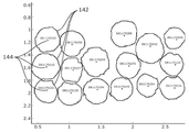
일 실시예에서, 데이터 프로세서 또는 프로세서들은, 로드 엔드 페이스의 스캔으로부터 식별되는 결정된 개별적인 로그 엔드 경계들의 개수에 기초하여 로그 카운트를 생성함으로써 출력 데이터를 생성하도록 구성될 수도 있고, 로그 로드를 나타내는 생성된 출력 데이터는 로그 로드의 로그들의 개수를 나타내는 로그 카운트를 포함한다.In one embodiment, the data processor or processors may be configured to generate output data by generating a log count based on the determined number of individual log end boundaries identified from the scan of the load end face, The output data includes a log count indicating the number of logs in the log load.
일 실시예에서, 핸드헬드 스캐너 유닛은, 스캔 동안 스캐너 유닛이 전체 로드 엔드 페이스에 걸쳐 스캔됨에 따라 깊이 화상들과 텍스처 화상들을 동시에 쌍으로 캡처하게끔 깊이 센서와 텍스처 센서를 동작시키도록 구성된다. 다른 일 실시예에서, 핸드헬드 스캐너 유닛은, 스캔 동안 캡처되는 깊이 화상들과 텍스처 화상들 중 적어도 일부가 예를 들어 깊이 센서와 텍스처 센서의 공통 트리거 신호에 기초하여 동일한 시각에 동시에 쌍으로 캡처되게끔 깊이 센서와 텍스처 센서를 동작시키도록 구성된다. 다른 일 실시예에서, 일련의 깊이 화상들과 텍스처 화상들은, 동일한 프레임 속도로 또는 서로 다른 프레임 속도로 서로 독립적으로 캡처될 수도 있다.In one embodiment, the handheld scanner unit is configured to operate the depth sensor and texture sensor to simultaneously capture depth images and texture images in pairs as the scanner unit is scanned across the full load endface during a scan. In another embodiment, the handheld scanner unit is configured such that at least some of the depth images and texture images captured during the scan are simultaneously captured in pairs at the same time based on the common trigger signal of the depth sensor and the texture sensor The depth sensor and the texture sensor. In another embodiment, a series of depth images and texture images may be captured independently of each other at the same frame rate or at different frame rates.
일 실시예에서, 각 깊이 화상과 텍스처 화상은 로드 엔드 페이스의 일부를 캡처한다. 일 형태에 있어서, 깊이 센서와 텍스처 센서의 시야는, 로드 엔드 페이스로부터 소정의 이격 거리에서 동작시 깊이 화상들과 텍스처 화상들의 각 쌍마다 총 로드 엔드 페이스의 일부만을 캡처한다. 본 실시예에서, 일련의 깊이 화상들과 텍스처 화상들의 쌍들은 스캔의 완료시 전체 로드 엔드 페이스를 총괄적으로 캡처한다.In one embodiment, each depth image and texture image captures a portion of the road end face. In one aspect, the field of view of the depth sensor and the texture sensor captures only a portion of the total load end face for each pair of depth images and texture images in operation at a predetermined distance from the rod end face. In this embodiment, a series of depth images and pairs of texture images collectively capture the entire load-end face at the completion of the scan.
일 실시예에서, 핸드헬드 스캐너 유닛의 깊이 센서는 깊이 카메라이다. 일 형태에 있어서, 깊이 센서는 잡음을 감소시키는 필터를 포함한다. 일례로, 깊이 카메라는 적외선 주파수에서 동작하고, 필터는 적외선(IR) 필터이다. 다른 형태들에서, 깊이 센서는 어떠한 필터도 사용하지 않는다.In one embodiment, the depth sensor of the handheld scanner unit is a depth camera. In one aspect, the depth sensor includes a filter that reduces noise. As an example, the depth camera operates at the infrared frequency and the filter is an infrared (IR) filter. In other versions, the depth sensor does not use any filters.
다른 일 실시예에서, 핸드헬드 스캐너 유닛의 깊이 센서는 스테레오 카메라이다.In another embodiment, the depth sensor of the handheld scanner unit is a stereo camera.
일 실시예에서, 핸드헬드 스캐너 유닛의 텍스처 센서는 텍스처 카메라이다. 일 형태에 있어서, 텍스처 카메라는 모노크롬 카메라이다. 이 형태에서, 모노크롬 카메라는, 로그 엔드들의 우드-바크(wood-bark) 경계를 결정하기 위해 텍스처 화상을 향상시키도록 구성된 칼라 필터 또는 필터들을 구비할 수도 있다. 칼라 필터의 특성들은 로그 종에 의존할 수도 있다. 다른 형태들에서, 모노크롬 카메라는 어떠한 필터 또는 필터들도 사용하지 않는다. 다른 형태에서, 텍스처 카메라는 칼라 카메라이다.In one embodiment, the texture sensor of the handheld scanner unit is a textured camera. In one form, the texture camera is a monochrome camera. In this form, the monochrome camera may have color filters or filters configured to enhance the texture image to determine the wood-bark boundaries of the log ends. The characteristics of the color filter may depend on the log species. In other aspects, the monochrome camera does not use any filters or filters. In another form, the texture camera is a color camera.
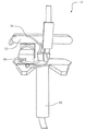
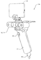
일 실시예에서, 핸드헬드 스캐너 유닛은 사용자의 손 또는 손들로 파지하기 위한 핸들 또는 핸들 조립체를 포함한다. 본 실시예에서, 깊이 카메라와 텍스처 카메라는 핸들 또는 핸들 조립체에 장착되거나 핸들 또는 핸들 조립체에 의해 반송된다.In one embodiment, the handheld scanner unit includes a handle or handle assembly for gripping with the user's hand or hands. In this embodiment, the depth camera and the texture camera are mounted on a handle or handle assembly or carried by a handle or a handle assembly.
일 실시예에서, 핸드헬드 스캐너 유닛은, 핸드헬드 스캐너 유닛이 로드 엔드 페이스에 걸쳐 스캔된 후 스캔의 완료시 화상 캡처를 중단할 때 깊이 화상들과 텍스처 화상들의 캡처를 개시하는 트리거 버튼의 기동에 응답하여 기동 신호를 생성함으로써 스캔을 개시 및 정지하도록 사용자에 의해 동작가능한 동작가능 트리거 버튼을 포함한다.In one embodiment, the handheld scanner unit is configured to trigger the trigger button to initiate capture of the depth images and texture images when the handheld scanner unit is scanned across the road end face, And an activatable trigger button operable by the user to initiate and stop the scan by generating a start signal in response.
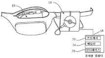
일 실시예에서, 시스템은, 핸드헬드 스캐너 유닛에 동작가능하게 접속되고 스캔 피드백을 사용자에게 표시하도록 구성된 표시 스크린을 갖는 조작자 인터페이스 장치를 더 포함한다. 일 형태에 있어서, 표시 화면 상에 표시된 스캔 피드백은, 깊이와 텍스처 카메라들의 시야에 있거나 캡처되고 있는 깊이 화상들 및/또는 텍스처 화상들의 실시간 가시화이다. 다른 형태에서, 스캔 피드백은 스캔 동안 생성되고 있는 로드 엔드 페이스의 데이터 모델의 실시간 가시화이다.In one embodiment, the system further includes an operator interface device operatively connected to the handheld scanner unit and having a display screen configured to display scan feedback to a user. In one aspect, the scan feedback displayed on the display screen is a real-time visualization of depth and / or texture images being in or out of view of the depth and texture cameras. In another form, the scan feedback is a real-time visualization of the data model of the load end face being generated during the scan.
일 실시예에서, 핸드헬드 스캐너 유닛은 제어기를 더 포함한다. 일 형태에 있어서, 제어기는, 핸드헬드 스캐너 유닛에 동작가능하게 접속된 별도의 장치이다. 다른 일 형태에서, 제어기는 핸드헬드 스캐너 유닛과 함께 집적된다.In one embodiment, the handheld scanner unit further comprises a controller. In an aspect, the controller is a separate device operatively connected to the handheld scanner unit. In another form, the controller is integrated with the handheld scanner unit.
일 실시예에서, 핸드헬드 스캐너 유닛의 제어기는, 적어도 깊이 카메라 및 텍스처 카메라에 동작가능하게 접속되고, 깊이 및 텍스처 카메라들을 제어하도록 동작가능하다. 일례로, 제어기는, 또한, 데이터 프로세서 또는 프로세서들에 송신하게끔 카메라들에 의해 생성되는 캡처된 깊이 및 텍스처 화상들을 압축하도록 구성된다.In one embodiment, the controller of the handheld scanner unit is operably connected to at least the depth camera and the texture camera, and is operable to control depth and texture cameras. In one example, the controller is further configured to compress the captured depth and texture images generated by the cameras to transmit to a data processor or processors.
일 실시예에서, 핸드헬드 스캐너 유닛은, 스캔을 개시 및 정지하도록 트리거 버튼의 기동 신호를 생성하게끔 사용자에 의해 동작가능한 동작가능 트리거 버튼을 더 포함하고, 핸드헬드 스캐너 유닛의 제어기는, 또한, 트리거 버튼에 동작가능하게 접속되고, 트리거 버튼의 기동 신호를 수신하여 처리하고, 트리거 버튼 기동 신호에 기초하여 깊이 카메라와 텍스처 카메라를 동작시켜 스캔에 대한 캡처를 개시 또는 중단하게 한다.In one embodiment, the handheld scanner unit further comprises an operable trigger button operable by a user to generate a trigger signal of a trigger button to start and stop a scan, and the controller of the handheld scanner unit further includes a trigger And receives and processes the trigger signal of the trigger button and causes the depth camera and the texture camera to operate based on the trigger button start signal to start or stop capturing for the scan.
일 실시예에서, 핸드헬드 스캐너 유닛은, 핸드헬드 스캐너 유닛의 이동 및/또는 위치를 검출하고 대표적 이동 신호를 생성하도록 구성된 관성 센서를 더 포함하고, 핸드헬드 스캐너 유닛의 제어기는, 또한, 관성 센서에 동작가능하게 접속되고, 생성된 이동 신호를 데이터 프로세서 또는 프로세서들에 대하여 수신 및 송신하도록 구성된다. 일 형태에 있어서, 관성 센서는, 스캔 동안 가속도계 신호 또는 값의 형태로 이동 신호를 생성하도록 구성된 3축 가속도계이다.In one embodiment, the handheld scanner unit further comprises an inertial sensor configured to detect movement and / or position of the handheld scanner unit and to generate a representative movement signal, wherein the controller of the handheld scanner unit further comprises an inertial sensor And is configured to receive and transmit the generated mobile signal to a data processor or processors. In one aspect, the inertial sensor is a three-axis accelerometer configured to generate a motion signal in the form of an accelerometer signal or value during a scan.
일 실시예에서, 핸드헬드 스캐너 유닛은 데이터 프로세서 또는 프로세서들과는 별도의 장치이다. 본 실시예에서, 핸드헬드 스캐너 유닛은, 유선형 또는 무선형일 수도 있는 데이터 링크를 통해 데이터 프로세서와 통신하도록 구성된다. 일 형태에 있어서, 핸드헬드 스캐너 유닛은, 무선 데이터 링크를 통해 데이터 프로세서 또는 프로세서에 스캔 데이터(예를 들어, 깊이 화상, 텍스처 화상, 가속도계 신호)를 송신하도록 구성된 통신 모듈과 함께 구성된다. 스캔 데이터는, 취득될 때 실시간으로 또는 스캔의 종료시 대량으로 데이터 프로세서 또는 프로세서들에 송신되거나 스트리밍될 수도 있다.In one embodiment, the handheld scanner unit is a separate device from the data processor or processors. In this embodiment, the handheld scanner unit is configured to communicate with the data processor over a data link, which may be streamlined or wireless. In an aspect, a handheld scanner unit is configured with a communication module configured to transmit scan data (e.g., depth image, texture image, accelerometer signal) to a data processor or processor over a wireless data link. The scan data may be transmitted or streamed to the data processor or processors in real time as it is acquired, or in bulk at the end of the scan.
일 실시예에서, 깊이 카메라와 텍스처 카메라는, 일련의 또는 세트의 깊이 화상들과 텍스처 화상들의 각 쌍이 스캔 동안 각 시각에 취득되도록 동기화된다. 일 실시예에서, 스캔 동안 취득되는 연속적인 깊이 화상과 텍스처 화상 쌍들의 개수는 스캔 동안 조작자에 의해 결정되는 바와 같은 스캔 시간과 카메라의 구성가능 프레임 속도에 의존한다.In one embodiment, the depth camera and the texture camera are synchronized so that each pair of depth images and texture images in a series or set is acquired at each time during the scan. In one embodiment, the number of consecutive depth and texture picture pairs acquired during a scan depends on the scan time and the configurable frame rate of the camera as determined by the operator during the scan.
일 실시예에서, 핸드헬드 스캐너 유닛은, 스캔되고 있는 로드 엔드 페이스로부터의 소정의 이격 거리 또는 범위에서 조작자에 의해 유지되도록 구성된다. 일 구성에 있어서, 이격 거리는, 로드 엔드 페이스로부터 약 1.5m 내지 약 2m일 수도 있지만, 대체 구성에서, 이격 거리는 더 가깝거나 멀 수도 있다.In one embodiment, the handheld scanner unit is configured to be held by an operator at a predetermined distance or range from the rod end face being scanned. In one configuration, the spacing may be from about 1.5 m to about 2 m from the rod end face, but in alternative configurations, the spacing distance may be closer or further.
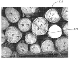
일 실시예에서, 각 로그의 ID 요소들은 기계 판독가능 인쇄 코드이며, 각 기계 판독가능 인쇄 코드는, 자신의 각 로그에 할당된 인코딩된 고유의 로그 ID 데이터 또는 코드를 포함한다. 일 형태에 있어서, ID 요소들은, 로그 로드의 각 로그의 로그 엔드 페이스에 고정된 인쇄 바코드 또는 QR 코드의 형태로 된 ID 태그들이다. 일 형태에 있어서, ID 태그들은 로그 엔드들에 부착된 인쇄 시트의 형태일 수도 있다.In one embodiment, the ID elements of each log are machine readable print codes, and each machine readable print code contains encoded unique log ID data or code assigned to each of its logs. In one form, the ID elements are ID tags in the form of a printed bar code or QR code fixed at the log end face of each log of the log load. In one form, the ID tags may be in the form of a printed sheet attached to log ends.
일 실시예에서, 데이터 프로세서 또는 프로세서들은, 핸드헬드 스캐너 유닛으로부터 수신되는 깊이 화상들과 텍스처 화상들을 각자의 압축 해제된 초기 깊이 화상들과 텍스처 화상들로 압축 해제하도록 구성된다.In one embodiment, the data processor or processors are configured to decompress the depth images and texture images received from the handheld scanner unit into their decompressed initial depth images and texture images.
일 실시예에서, 데이터 프로세서 또는 프로세서들은, 각 텍스처 화상을 처리하여 볼 수 있는 ID 요소들을 식별하고, 볼 수 있는 ID 요소들의 각각을 디코딩하여 각자의 고유한 로그 ID 코드들을 추출하고, 각 텍스처 화상의 ID 요소들의 위치 좌표들과 함께, 각 텍스처 화상에 관하여 추출된 고유한 로그 ID 코드들을 포함하는 데이터 파일을 생성 및 저장함으로써, 텍스처 화상들을 처리하여 스캔된 로드 엔드 페이스에서 볼 수 있는 ID 요소들을 식별 및 디코딩하도록 구성된다. 일 실시예에서, 데이터 프로세서 또는 프로세서들은, 또한, 각각의 고유한 로그 ID 코드가 텍스처 화상들의 세트에서 보인 횟수 및 텍스처 화상들의 세트의 처리로부터 추출된 각각의 고유한 로그 ID 코드를 포함하는 데이터 파일을 생성 및 저장하도록 구성된다.In one embodiment, the data processor or processors can identify each of the ID elements that can be viewed by viewing each texture image, decode each of the viewable ID elements to extract their unique log ID codes, By generating and storing a data file containing the unique log ID codes extracted for each texture image, together with the location coordinates of the ID elements of the texture image, Identified and decoded. In one embodiment, the data processor or processors also include a data file that contains each unique log ID code extracted from the set of texture images and the number of times it has been seen in the set of texture images, As shown in FIG.
일 실시예에서, 데이터 프로세서 또는 프로세서들은, 깊이 화상들, 또는 깊이 화상들과 텍스처 화상들을 처리하여 캡처된 각 깊이 화상, 또는 깊이 화상과 텍스처 화상에서의 핸드헬드 스캐너 유닛의 포즈를 추정하고, 각 깊이 화상, 또는 깊이 화상과 텍스처 화상에 연관된 포즈 추정 데이터를 생성하고, 깊이 화상들, 또는 깊이 화상들과 텍스처 화상들, 및 포즈 추정 데이터를 공간 데이터 구조의 형태로 된 데이터 모델로 처리함으로써, 깊이 화상들, 또는 깊이 화상들과 텍스처 화상들을 로드 엔드 페이스의 데이터 모델로 융합하도록 구성된다.In one embodiment, the data processor or processors process depth images, or depth images and texture images, to estimate a pose of the handheld scanner unit in each depth image captured, or depth and texture images, By producing pose estimation data associated with a depth image or a depth image and a texture image and processing depth images or depth images and texture images and pose estimation data with a data model in the form of a spatial data structure, Images, or depth images and texture images into a data model at the road end face.
일 실시예에서, 포즈 추정은, 각 깊이 화상, 또는 각 깊이 화상과 텍스처 화상에 대하여 스캐너 핸드헬드 유닛의 포즈를 추정하도록 3D 자기 위치맞춤(self-registration)을 수행하는 포즈 추정 알고리즘을 실행함으로써, 깊이 화상들, 또는 깊이 화상들과 텍스처 화상들로부터 생성된다. 일 형태에 있어서, 포즈 추정 알고리즘은 포즈 추정을 생성하도록 점-평면 오차 함수(point-plane error function)를 실행한다.In one embodiment, the pose estimation is performed by executing a pose estimation algorithm that performs 3D self-registration to estimate the pose of the scanner handheld unit for each depth image, or for each depth image and texture image, Depth images, or depth images and texture images. In one aspect, the pose estimation algorithm performs a point-plane error function to produce a pose estimate.
일 실시예에서, 깊이 화상들, 또는 깊이 화상들과 텍스처 화상들은, 포즈 추정 데이터에 기초하여 절단 부호 거리 함수(truncated signed distance function; TSDF)의 형태의 데이터 모델로 융합된다.In one embodiment, depth images, or depth images and texture images, are fused into a data model in the form of a truncated signed distance function (TSDF) based on pose estimation data.
일 실시예에서, 데이터 프로세서 또는 프로세서들은, 깊이 화상들을 처리하여 캡처된 각 깊이 화상에서의 핸드헬드 스캐너 유닛의 포즈를 추정하고 각 깊이 화상에 연관된 포즈 추정 데이터를 생성하고, 깊이 화상들과 포즈 추정 데이터를 공간 데이터 구조의 형태로 된 데이터 모델로 처리함으로써, 깊이 화상들을 로드 엔드 페이스의 데이터 모델로 융합하도록 구성된다.In one embodiment, the data processor or processors process the depth images to estimate a pose of the handheld scanner unit in each captured depth image, generate pose estimation data associated with each depth image, Processing the data into a data model in the form of a spatial data structure, thereby fusing the depth images into a data model at the load end face.
일 실시예에서, 포즈 추정은, 각 깊이 화상에 대하여 스캐너 핸드헬드 유닛의 포즈를 추정하도록 3D 자기 위치맞춤을 수행하는 포즈 추정 알고리즘을 실행함으로써 깊이 화상들로부터 생성된다. 일 형태에 있어서, 포즈 추정 알고리즘은 점-평면 오차 함수를 실행하여 포즈 추정을 생성한다.In one embodiment, the pose estimation is generated from the depth images by executing a pose estimation algorithm that performs 3D self-alignment to estimate the pose of the scanner handheld unit for each depth image. In one aspect, the pose estimation algorithm performs a point-to-plane error function to generate a pose estimate.
일 실시예에서, 깊이 화상들은 포즈 추정 데이터에 기초하여 절단 부호 거리 함수(TSDF)의 형태의 데이터 모델로 융합된다.In one embodiment, the depth images are fused to a data model in the form of a truncation code distance function (TSDF) based on the pose estimation data.
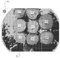
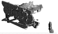
일 실시예에서, 데이터 프로세서 또는 프로세서들은, 데이터 모델을 처리하여 로드 엔드 페이스에 대하여 법선 방향인 레이캐스트 정사영 깊이 화상(raycast orthographic depth image)을 생성하고 레이캐스트 정사영 깊이 화상으로부터 로그 엔드 경계들을 추출함으로써, 로드 엔드 페이스에서 볼 수 있는 개별적인 로그들의 로그 엔드 경계들을 생성하도록 구성된다. 일 형태에 있어서, 핸드헬드 스캐너 유닛은, 핸드헬드 스캐너 유닛의 이동 및/또는 위치를 검출하고 대표적 이동 신호를 생성하도록 구성된 관성 센서를 더 포함하고, 레이캐스트 정사영 깊이 화상을 생성하는 것은, 이동 신호와 데이터 모델(예를 들어, TSDF)에 기초하여 로드 엔드 페이스의 하향 방향과 법선 방향을 결정하는 것을 포함한다. 일례로, 관성 센서는 가속도계 신호를 생성하는 3축 가속도계이다.In one embodiment, the data processor or processors process the data model to generate a raycast orthographic depth image that is normal to the road end face and to extract log end boundaries from the racast orthorotm depth image , And are configured to generate log end boundaries of individual logs visible at the load end face. In one form, the handheld scanner unit further comprises an inertial sensor configured to detect movement and / or position of the handheld scanner unit and to generate a representative movement signal, wherein generating a racast true- And determining a downward and normal direction of the load endface based on the data model (e.g., TSDF). For example, an inertial sensor is a three-axis accelerometer that generates an accelerometer signal.
일 실시예에서, 데이터 프로세서 또는 프로세서들은, 또한, 로드 엔드 페이스의 레이캐스트 정사영 법선 화상을 생성하도록 구성된다. 일 형태에 있어서, 데이터 프로세서 또는 프로세서들은, 레이캐스트 정사영 법선 화상에 기초하여 레이캐스트 정사영 깊이 화상을 화상 처리하여 로그들의 사이드 또는 및/또는 넌로그(non-log) 특징부 또는 유사부들을 제거하는 더욱 클린한(cleaner) 레이캐스트 정사영 깊이 화상을 생성하도록 구성되고, 클리닝된 레이캐스트 정사영 깊이 화상을 처리하여 로그 엔드 경계들을 결정한다.In one embodiment, the data processor or processors are also configured to generate a racast orthogonal normal image of the road end face. In one form, the data processor or processors are configured to process the racast true depth image based on the racast orthogonal normal image to remove side and / or non-log features or similar portions of logs A cleaner raycast is configured to produce a true depth image and processes the cleaned racast true depth image to determine log end boundaries.
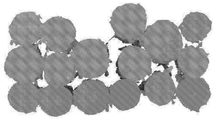
일 실시예에서, 레이캐스트 정사영 깊이 화상으로부터 결정되는 로그 엔드 경계들은, 데이터 프로세서 또는 프로세서들에 의해 추가로 개선된다. 일 형태에 있어서, 데이터 프로세서 또는 프로세서들은, 결정된 로그 엔드 경계들을 캡처된 텍스처 화상들 중 하나 이상으로 변환 및 투영하고, 투영된 로그 엔드 경계들의 영역에 있는 텍스처 화상들을 처리하여 우드-바크 경계를 검출하도록 구성된다. 일 형태에 있어서, 그 처리는, 텍스처 화상들을 처리하여 각 로그마다 우드-바크 경계면을 검출하고 투영된 로그 엔드 경계를 검출된 우드-바크 경계로 조정하여 각 로그마다 개선된 언더-바크(under-bark) 로그 엔드 경계를 생성하도록 구성된 세그먼트화 알고리즘을 실행한다.In one embodiment, the log end boundaries determined from the racast ultra-deep depth image are further refined by the data processor or processors. In one aspect, a data processor or processors are configured to convert and project the determined log end boundaries into one or more of the captured texture images, process the texture images in the region of the projected log end boundaries to detect the Wood- . In one aspect, the process includes processing texture images to detect a Wood-Bark interface for each log and adjusting the projected log-end boundary to a detected Wood-Bark boundary to provide an improved under- bark) run end segmentation algorithm to generate a log end boundary.
일 실시예에서, 데이터 프로세서 또는 프로세서들은, 데이터 모델을 처리하여 하나 이상의 레이캐스트 화상을 생성하고 레이캐스트 화상들로부터 로그 엔드 경계들을 추출함으로써, 로드 엔드 페이스에서 볼 수 있는 개별적인 로그들의 로그 엔드 경계들을 생성하도록 구성된다. 일 형태에 있어서, 핸드헬드 스캐너 유닛은, 핸드헬드 스캐너 유닛의 이동 및/또는 위치를 검출하고 대표적 이동 신호를 생성하도록 구성된 관성 센서를 더 포함하고, 하나 이상의 레이캐스트 화상을 생성하는 것은, 이동 신호와 데이터 모델에 기초하여 로드 엔드 페이스의 하향 방향과 법선 방향을 결정하는 것을 포함한다.In one embodiment, the data processor or processors process the data model to generate one or more racast pictures and extract log end boundaries from the racast pictures to obtain log end boundaries of the individual logs visible at the load end face Respectively. In one aspect, a handheld scanner unit further comprises an inertial sensor configured to detect movement and / or position of the handheld scanner unit and to generate a representative movement signal, wherein generating one or more racast images comprises: And determining a downward direction and a normal direction of the road end face based on the data model.
일 실시예에서, 하나 이상의 레이캐스트 화상은 레이캐스트 깊이 화상을 포함하고, 데이터 프로세서 또는 프로세서들은, 또한, 로드 엔드 페이스의 레이캐스트 법선 화상을 생성한 후, 레이캐스트 법선 화상에 기초하여 레이캐스트 깊이 화상을 추가로 화상 처리하여 로그들의 사이드들 및/또는 넌로그 특징부들을 제거하는 클리닝된 레이캐스트 깊이 화상을 생성하도록 구성되고, 클리닝된 레이캐스트 깊이 화상은 로그 엔드 경계들을 결정하도록 처리된다.In one embodiment, the at least one racast picture comprises a racast depth picture, and the data processor or processors are further configured to generate a racast normal picture of the road end face, The image is further processed to produce a cleaned racast depth image that eliminates side and / or non-log features of logs, and the cleaned racast depth image is processed to determine log end boundaries.
일 실시예에서, 하나 이상의 레이캐스트 화상으로부터 결정되는 로그 엔드 경계들은, 결정된 로그 엔드 경계들을 캡처된 텍스처 화상들 중 하나 이상으로 변환 및 투영하고, 텍스처 화상들을 처리하여 각 로그마다 우드-바크 경계면을 검출하고 투영된 로그 엔드 경계를 검출된 우드-바크 경계로 조정하여 각 로그마다 개선된 언더-바크 로그 엔드 경계를 생성하도록 구성된 세그먼트화 알고리즘을 실행함으로써 투영된 로그 엔드 경계들의 영역에 있는 텍스처 화상들을 처리하여 우드-바크 경계를 검출함으로써, 데이터 프로세서 또는 프로세서에 의해 또한 개선된다.In one embodiment, the log end boundaries determined from the one or more racast pictures are converted and projected to one or more of the captured texture images, the determined log end boundaries are processed, the texture images are processed, and a Wood- By running a segmentation algorithm configured to detect and project the projected log end boundaries to the detected Wood-Bark boundaries to produce an improved under-bark log end boundary for each log, the texture images in the region of the projected log end boundaries Processing, and detecting the Wood-Bark boundary by the data processor or processor.
일부 실시예들에서, 레이캐스트 화상들은 정사영일 수도 있고 또는 정사영이 아닐 수도 있으며, 이들의 개별적인 요소들(픽셀들)은 깊이 값, 법선 값, 복셀 점유를 나타내는 비트 패턴 등 중 임의의 하나 이상을 포함할 수도 있다.In some embodiments, the racast pictures may be orthogonal or non-orthogonal, and their individual elements (pixels) may include any one or more of a depth value, a normal value, a bit pattern indicative of voxel occupancy, .
일 실시예에서, 데이터 프로세서 또는 프로세서들은 로그들의 각각에 대하여 바크가 예상되지 않는 내측 통계 경계를 생성하도록 구성되고, 세그먼트화 알고리즘은, 각 로그 엔드에 대하여 투영된 결정된(외측) 로그 엔드 경계와 내측 통계 경계 사이에 위치하는 텍스처 화상들의 환형 영역들만을 처리하는 것으로 제한된다. 일 형태에 있어서, 통계 경계는, 스캔되고 있는 로그의 종에 대하여 예상되는 최대 바크 두께를 나타내는 저장된 통계 데이터에 기초하여 생성된다.In one embodiment, the data processor or processors are configured to generate an inner statistical boundary where Bark is not expected for each of the logs, and the segmentation algorithm comprises a determined (outer) log end boundary projected for each log end, Is limited to processing only annular areas of texture images located between the statistical boundaries. In one form, the statistical boundaries are generated based on stored statistical data indicating the maximum expected Bark thickness for the species of log being scanned.
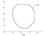
일 실시예에서, 데이터 프로세서 또는 프로세서들은, 결정된 또는 개선된 로그 엔드 경계들에 기초하여 로그 엔드들의 하나 이상의 물리적 특성을 측정하여 각 로그에 대하여 대표적 로그 엔드 경계를 생성한 후 각 로그에 대하여 로그 엔드 경계 데이터를 포함하는 로그 로드를 나타내는 출력 데이터를 생성함으로써, 출력 데이터를 생성하도록 구성되고, 데이터 프로세서 또는 프로세서들은, 각 로그 엔드 페이스에 연관된 평면들을 산출하고 결정된 또는 개선된 로그 엔드 경계들을 산출된 로그 엔드 평면들 상에 각각 투영하고, 로그 엔드 경계들과 평면들을 미터법 체계 좌표계로 변환하고, 변환된 로그 엔드 경계들에 기초하여 로그 엔드들의 하나 이상의 물리적 특성을 측정함으로써, 로그 엔드들의 물리적 특성을 측정하도록 구성된다.In one embodiment, the data processor or processors measure one or more physical characteristics of the log ends based on the determined or improved log end boundaries to generate representative log end boundaries for each log, and then, for each log, Wherein the data processor or processors are configured to generate output data indicative of a log load comprising boundary data and wherein the data processor or processors are configured to calculate the planes associated with each log endface and to determine determined or enhanced log end boundaries By measuring one or more physical properties of the log ends based on the converted log end boundaries, translating the log end boundaries and planes into a metric system coordinate system, and measuring the physical properties of the log ends .
일 형태에 있어서, 각 로그 엔드의 물리적 특성은, 로그 엔드 경계 중심, 단축, 직교축, 및 결정된 축들을 따른 로그 직경들 중 임의의 하나 이상을 포함할 수도 있다.In one form, the physical properties of each log end may include any one or more of the log end boundary center, minor axis, orthogonal axis, and logarithmic along the determined axes.
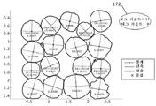
일 실시예에서, 데이터 프로세서 또는 프로세서들은, 텍스처 화상들에 기초하여 ID 요소들의 중심을 삼각 측량하여 어느 ID 요소가 어느 로그 엔드 경계 및 이 경계에 연관된 로그 엔드 경계 데이터에 대응하는지를 검출하고, 이 대응 관계를 나타내는 생성된 링크 또는 연관성을 포함하는 로그 로드를 나타내는 출력 데이터를 생성함으로써, 추출된 개별적인 로그 ID 데이터와 이러한 각 데이터의 로그 엔드 경계 데이터 간의 링크 또는 연관성을 생성하도록 구성된다.In one embodiment, the data processor or processors triangulate the center of the ID elements based on the texture images to detect which log edge corresponds to which log end boundary and log end boundary data associated with this boundary, To generate a link or association between the extracted individual log ID data and the log end boundary data of each such data by generating output data representing the log load including the generated link or association representing the relationship.
일 실시예에서, 데이터 프로세서 또는 프로세서들은, 또한, 데이터 파일 또는 메모리에 로그 로드를 나타내는 출력 데이터를 출력 및/또는 저장하도록 구성된다. 일례로, 출력 데이터는 로그 ID 데이터 및 로그 카운트를 포함할 수도 있다. 로그 카운트는, 예를 들어, 스캔으로부터 식별되는 개별적인 로그 엔드 경계들의 개수에 기초할 수도 있다. 다른 일례로, 출력 데이터는, 로그 ID 데이터, 측정된 로그 엔드 경계 데이터, 및 로그 ID 데이터와 측정된 로그 엔드 경계 데이터 간의 링크나 연관성을 포함할 수도 있다. 또 다른 일례로, 출력 데이터는, 로그 ID 데이터, 로그 카운트, 측정된 로그 엔드 경계 데이터, 및 로그 ID 데이터와 측정된 로그 엔드 경계 데이터 간의 링크나 연관성을 포함할 수도 있다. In one embodiment, the data processor or processors are also configured to output and / or store output data indicative of a log load to a data file or memory. In one example, the output data may include log ID data and a log count. The log count may be based, for example, on the number of individual log end boundaries identified from the scan. In another example, the output data may include a link or association between log ID data, measured log end boundary data, and log ID data and measured log end boundary data. As another example, the output data may include the log ID data, the log count, the measured log end boundary data, and the link or association between the log ID data and the measured log end boundary data.
일 형태에 있어서, 출력 데이터는 데이터 파일이나 메모리에 저장될 수도 있다. 다른 형태에 있어서, 출력 데이터는 표시 스크린 상에 표시될 수도 있다. 또 다른 형태에 있어서, 출력 데이터는 표 및/또는 도식적 보고서의 형태로 된다.In one form, the output data may be stored in a data file or memory. In another form, the output data may be displayed on the display screen. In another aspect, the output data is in the form of a table and / or graphical report.
일 실시예에서, 로그 로드는 핸드헬드 스캐너 유닛에 의해 스캔되는 경우 이송 차량 상의 제 위치에 있다. 이송 차량은, 예를 들어, 벌목 트럭이나 트레일러, 레일웨이 왜건, 또는 로그 로더일 수도 있다. 다른 일 실시예에서, 로그 로드는, 예를 들어, 지상이나 로그 크레이들 등의 다른 표면 상에 놓여있을 수도 있다.In one embodiment, the log load is in place on the transport vehicle when scanned by the handheld scanner unit. The transport vehicle may be, for example, a logging truck or a trailer, a railway wagon, or a log loader. In another embodiment, the log load may be on other surfaces, such as, for example, ground or log cradles.
일 실시예에서, ID 요소들은 로그 로드의 로그들의 각각의 작은 엔드 상에만 제공된다.In one embodiment, the ID elements are provided only on each small end of the logs of the log load.
일 실시예에서, 로그 로드가 동일한 로드 엔드 페이스에서 로그들의 모든 작은 엔드를 포함하는 경우, 시스템은 작은 엔드들을 포함하는 로드 엔드 페이스의 스캔으로부터의 데이터만 처리하도록 구성된다. 다른 일 실시예에서, 로그 로드가 로그 로드의 양측 엔드 간에 혼합된 로그들의 작은 엔드들을 포함하는 경우, 시스템은, 로그 로드의 각 로드 엔드 페이스마다 하나의 스캔이 해당하는 두 개의 별도의 스캔으로부터의 데이터를 수신 및 처리하고, 양측 스캔으로부터의 출력 데이터를 결합하거나 병합하도록 구성된다.In one embodiment, if the log load includes all the small ends of the logs at the same load end face, then the system is configured to process only the data from the scan of the load end face including the small ends. In another embodiment, if the log load includes small endings of mixed logs between the two ends of the log load, the system may determine that each load endface of the log load is from two separate scans, Receive and process the data, and combine or merge the output data from both sides of the scan.
일 실시예에서, 로그 스캔 시스템은, 핸드헬드 스캐너 유닛이 장착되거나 반송되는 동작가능 전기식 반송 시스템(powered carrier system)을 더 포함하고, 반송 시스템은, 로드 엔드 페이스를 자동으로 스캔하거나 조작자에 의한 수동 제어에 응답하여 스캔하게끔 로그 로드에 대하여 핸드헬드 스캐너 유닛을 이동시키도록 구성된다.In one embodiment, the log scan system further comprises an operable electrical carrier system in which the handheld scanner unit is mounted or transported, and the transport system is configured to automatically scan the rod end face or manually And to move the hand held scanner unit relative to the log load to scan in response to the control.
일 실시예에서, 데이터 프로세서 또는 프로세서들은, 깊이 화상들, 또는 깊이 화상들과 텍스처 화상들을 로드 엔드 페이스의 데이터 모델로 융합하도록 구성된다.In one embodiment, the data processor or processors are configured to fuse depth images, or depth images and texture images, into a data model at the road end face.
제2양태에서, 본 발명은 로그들의 로드(로그 로드)를 식별 및 측정하는 방법으로 주로 이루어지며, 로그 로드의 각각의 개별적인 로그는 적어도 하나의 로그 엔드 페이스 상에 고유한 로그 ID 데이터를 포함하는 ID 요소를 포함하며, 이러한 방법은, 깊이 센서와 텍스처 센서를 포함하는 핸드헬드 스캐너 유닛에 의해 로그 로드의 로드 엔드 페이스를 스캔하여 로드 엔드 페이스의 일련의 깊이 화상들과 텍스처 화상들을 취득하는 단계; 깊이 화상들을 로드 엔드 페이스의 데이터 모델로 융합하는 단계; 데이터 모델을 처리함으로써 로드 엔드 페이스에서 볼 수 있는 개별적인 로그들의 로그 엔드 경계들을 결정하는 단계; 텍스처 화상들을 처리하여 스캔된 로드 엔드 페이스에서 볼 수 있는 임의의 ID 요소들을 식별 및 디코딩하여 로그 로드의 개별적인 로그들에 대하여 개별적인 로그 ID 데이터를 추출하는 단계; 및 결정된 로그 엔드 경계들과 추출된 로그 ID 데이터에 기초하여 로그 로드를 나타내는 출력 데이터를 생성하는 단계를 포함한다.In a second aspect, the present invention consists primarily of a method for identifying and measuring a load (log load) of logs, wherein each individual log of the log load includes unique log ID data on at least one log end face The method comprising scanning a rod end face of a log load with a handheld scanner unit including a depth sensor and a texture sensor to obtain a series of depth images and texture images of the rod end face; Fusing the deep images into a data model at the road end face; Determining log end boundaries of individual logs visible at the load end face by processing the data model; Processing the texture images to identify and decode any ID elements visible at the scanned road end face to extract individual log ID data for the individual logs of the log load; And generating output data indicative of a log load based on the determined log end boundaries and the extracted log ID data.
일 실시예에서, 출력 데이터를 생성하는 단계는, 각 로드마다 대표적 로그 엔드 경계 데이터를 생성하게끔 결정된 로그 엔드 경계들에 기초하여 로그 엔드들의 하나 이상의 물리적 특성을 측정하는 단계를 포함하고, 로그 로드를 나타내는 생성된 출력 데이터는 각 로그에 대한 로그 엔드 경계 데이터를 포함한다.In one embodiment, generating output data comprises measuring one or more physical characteristics of log ends based on log end boundaries determined to generate representative log end boundary data for each load, The generated output data representing the log end boundary data for each log.
일 실시예에서, 방법은, 생성된 개별적인 로그 ID 데이터와 이 개별적인 로그의 각 로그 엔드 경계 데이터 간의 링크 또는 연관성을 생성하는 단계를 더 포함하고, 로그 로드를 나타내는 생성된 출력 데이터는, 개별적인 로그 ID 데이터와 이 개별적인 로그의 각 로그 엔드 경계 데이터 간의 링크 또는 연관성을 포함한다.In one embodiment, the method further comprises generating a link or association between the generated individual log ID data and each log end boundary data of the individual log, wherein the generated output data indicative of the log load includes a respective log ID Includes links or associations between the data and each log end boundary data of this individual log.
일 실시예에서, 출력 데이터를 생성하는 단계는, 로드 엔드 페이스의 스캔으로부터 식별되는 결정된 개별적인 로그 엔드 경계들의 개수에 기초하여 로그 카운트를 생성하는 단계를 포함하고, 로그 로드를 나타내는 생성된 출력 데이터는, 로그 로드의 로그들의 개수를 나타내는 로그 카운트를 포함한다.In one embodiment, generating the output data comprises generating a log count based on the determined number of individual log end boundaries identified from the scan of the load end face, wherein the generated output data indicative of the log load And a log count indicating the number of logs of the log load.
일 실시예에서, 방법은 로그 카운트를 포함하는 출력 데이터를 생성하는 단계를 더 포함한다. 일 형태에 있어서, 방법은 스캔으로부터 식별되는 개별적인 로그 엔드 경계들의 개수에 기초하여 로그 카운트를 생성하는 단계를 포함한다. 다른 일 형태에 있어서, 방법은 스캔으로부터 식별되는 개별적인 ID 요소들의 개수에 기초하여 로그 카운트를 생성하는 단계를 포함한다.In one embodiment, the method further comprises generating output data comprising a log count. In one aspect, the method includes generating a log count based on the number of individual log end boundaries identified from the scan. In another form, the method includes generating a log count based on the number of individual ID elements identified from the scan.
일 실시예에서, 로드 엔드 페이스를 스캔하는 단계는, 스캐너 유닛이 스캔 동안 전체 로드 엔드 페이스에 걸쳐 스캔됨에 따라 깊이 화상들과 텍스처 화상들을 동시에 쌍으로 캡처하게끔 핸드헬드 스캐너 유닛을 구성하거나 동작시키는 단계를 포함한다. 다른 일 실시예에서, 방법은, 예를 들어 공통 트리거 신호에 기초하여 스캔 동안 캡처되는 깊이 화상들과 텍스처 화상들 중 적어도 일부가 동일한 시각에 동시에 쌍으로 캡처되게끔 깊이 센서와 텍스처 센서를 동작시키도록 핸드헬드 스캐너 유닛을 구성하거나 동작시키는 단계를 포함한다. 다른 일 실시예에서, 방법은, 동일한 프레임 속도에서 또는 서로 다른 프레임 속도에서 일련의 깊이 화상들과 텍스처 화상들을 서로 독립적으로 캡처하도록 핸드헬드 스캐너 유닛을 구성하거나 동작시키는 단계를 포함한다.In one embodiment, scanning the rod end face comprises configuring or operating the handheld scanner unit to simultaneously capture depth images and texture images in pairs as the scanner unit is scanned across the full load endface during a scan . In another embodiment, the method operates the depth sensor and the texture sensor so that, for example, at least some of the depth images and texture images captured during a scan based on a common trigger signal are simultaneously captured in pairs at the same time And configuring or operating the handheld scanner unit. In another embodiment, the method includes configuring or operating the handheld scanner unit to capture a series of depth images and texture images independently of each other at the same frame rate or at different frame rates.
일 실시예에서, 로드 엔드 페이스를 스캔하는 단계는, 깊이 센서와 텍스처 센서의 시야가 깊이 화상들과 텍스처 화상들의 각 쌍에 대하여 총 로드 엔드 페이스의 일부만을 캡처하도록 핸드헬드 스캐너 유닛을 동작시키는 단계, 및 캡처된 일련의 깊이 화상들과 텍스처 화상들의 쌍들이 스캔의 완료시 전체 로드 엔드 페이스를 총괄적으로 캡처하도록 로드 엔드 페이스에 대하여 핸드헬드 스캐너 유닛을 이동시키는 단계를 포함한다.In one embodiment, scanning the rod end face includes operating the handheld scanner unit such that the field of view of the depth sensor and the texture sensor captures only a portion of the total load end face for each pair of depth images and texture images And moving the handheld scanner unit relative to the rod end face such that pairs of captured depth images and texture images collectively capture the entire load end face upon completion of the scan.
일 실시예에서, 텍스처 화상들을 처리하여 스캔된 로드 엔드 페이스에서 볼 수 있는 임의의 ID 요소들을 식별 및 디코딩하는 단계는, 각 텍스처 화상을 처리하여 볼 수 있는 ID 요소들을 식별하는 단계, 각각의 볼 수 있는 ID 요소를 디코딩하여 해당 요소의 고유한 로그 ID 코드를 추출하는 단계, 및 각 텍스처 화상의 ID 요소들의 위치 좌표들과 함께, 각 텍스처 화상에 관하여 추출된 고유한 로그 ID 코드를 포함하는 데이터 파일을 생성 및 저장하는 단계를 포함한다.In one embodiment, processing texture images to identify and decode any ID elements visible at the scanned road end face includes identifying ID elements that can be viewed by processing each texture image, And extracting a log ID code unique to the corresponding element from the input image data and the position coordinates of the ID elements of each texture image, And generating and storing the file.
일 실시예에서, 방법은, 텍스처 화상들의 세트의 처리로부터 추출된 각각의 고유한 로그 ID 코드 및 각각의 고유한 로그 ID 코드가 텍스처 화상들의 세트에서 보인 횟수를 포함하는 데이터 파일을 생성 및 저장하는 단계를 더 포함한다.In one embodiment, the method includes generating and storing a data file including each unique log ID code extracted from the processing of the set of texture images and the number of times each unique log ID code is seen in the set of texture images .
일 실시예에서, 깊이 화상들, 또는 깊이 화상들과 텍스처 화상들을 로드 엔드 페이스의 데이터 모델로 융합하는 단계는, 깊이 화상들, 또는 깊이 화상들과 텍스처 화상들을 처리하여 캡처된 각 깊이 화상, 또는 깊이 화상과 텍스처 화상에서의 핸드헬드 스캐너 유닛의 포즈를 추정하고, 각 깊이 화상, 또는 깊이 화상과 텍스처 화상에 연관된 포즈 추정 데이터를 생성하는 단계, 및 깊이 화상들, 또는 깊이 화상들과 텍스처 화상들, 및 포즈 추정 데이터를 처리하여 공간 데이터 구조의 형태인 데이터 모델로 되게 하는 단계를 포함한다.In one embodiment, fusing depth images, or depth images, and texture images into a data model at the road end face includes deeper images, or depth images captured by processing depth images and texture images, or Estimating a pose of the handheld scanner unit in a depth image and a texture image and generating pose estimation data associated with each depth image or a depth image and a texture image, And processing the pose estimation data into a data model in the form of a spatial data structure.
일 실시예에서, 방법은, 3D 자기 위치맞춤을 수행하는 포즈 추정 알고리즘을 실행하여 각 깊이 화상, 또는 깊이 화상과 텍스처 화상에 대한 스캐너 핸드헬드 유닛의 포즈를 추정함으로써 포즈 추정 데이터를 생성하는 단계를 포함한다. 일 형태에 있어서, 포즈 추정 알고리즘을 실행하는 단계는, 점-평면 오차 함수를 실행하여 포즈 추정을 생성하는 단계를 포함한다.In one embodiment, the method includes generating a pose estimation data by estimating a pose of the scanner handheld unit for each depth image, or a depth image and a texture image, by executing a pose estimation algorithm to perform 3D magnetic alignment . In one aspect, performing the pose estimation algorithm includes executing a point-plane error function to generate a pose estimate.
일 실시예에서, 깊이 화상들, 또는 깊이 화상들과 텍스처 화상들을 데이터 모델로 융합하는 단계는, 포즈 추정 데이터에 기초하여 깊이 화상들, 또는 깊이 화상들과 텍스처 화상들을 절단 부호 거리 함수(TSDF)로 융합하는 단계를 포함한다.In one embodiment, fusing depth images, or depth images, and texture images into a data model may include combining deep images, or depth images and texture images based on the pose estimation data, into a truncation sign distance function (TSDF) ≪ / RTI >
일 실시예에서, 깊이 화상들을 로드 엔드 페이스의 데이터 모델로 융합하는 단계는, 깊이 화상들을 처리하여 캡처된 각 깊이 화상에서의 핸드헬드 스캐너 유닛의 포즈를 추정하고 각 깊이 화상에 연관된 포즈 추정 데이터를 생성하는 단계, 및 깊이 화상들과 포즈 추정 데이터를 처리하여 공간 데이터 구조의 형태인 데이터 모델로 되게 하는 단계를 포함한다.In one embodiment, the step of fusing the depth images to the data model of the road end face comprises processing the depth images to estimate a pose of the handheld scanner unit in each captured depth image, And processing depth images and pose estimation data into a data model in the form of a spatial data structure.
일 실시예에서, 방법은, 3D 자기 위치맞춤을 수행하여 각 깊이 화상에 대한 스캐너 핸드헬드 유닛의 포즈를 추정하는 포즈 추정 알고리즘을 실행함으로써, 포즈 추정 데이터를 생성하는 단계를 포함한다. 일 형태에 있어서, 포즈 추정 알고리즘을 실행하는 단계는 점-평면 오차 함수를 실행하여 포즈 추정을 생성하는 단계를 포함한다.In one embodiment, the method includes generating pose estimation data by performing a 3D magnetic alignment to execute a pose estimation algorithm that estimates a pose of the scanner handheld unit for each depth image. In one aspect, performing the pose estimation algorithm includes executing a point-plane error function to generate a pose estimate.
일 실시예에서, 깊이 화상들을 데이터 모델로 융합하는 단계는, 포즈 추정 데이터에 기초하여 깊이 화상들을 절단 부호 거리 함수(TSDF)로 융합하는 단계를 포함한다.In one embodiment, fusing depth images to a data model includes fusing depth images to a truncation code distance function (TSDF) based on pose estimation data.
일 실시예에서, 로드 엔드 페이스에서 볼 수 있는 개별적인 로그들의 로그 엔드 경계들을 결정하는 단계는, 데이터 모델을 처리하여 로드 엔드 페이스에 대하여 법선 방향인 레이캐스트 정사영 깊이 화상을 생성하는 단계, 및 레이캐스트 정사영 깊이 화상으로부터 로그 엔드 경계들을 추출하는 단계를 포함한다.In one embodiment, determining the log end boundaries of the individual logs visible at the road end face includes processing the data model to produce a racast orthorhance depth image that is normal to the road end face, And extracting log end boundaries from the orthogonal depth image.
일 실시예에서, 방법은, 관성 센서에 의해 핸드헬드 스캐너 유닛의 관성 이동을 측정하고 대표적 관성 신호를 생성하는 단계를 더 포함하고, 레이캐스트 정사영 깊이 화상을 생성하는 단계는, 관성 신호와 데이터 모델(예를 들어, TSDF)에 기초하여 로드 엔드 페이스의 하향 방향과 법선 방향을 결정하는 단계를 포함한다. 일 형태에 있어서, 관성 센서는 대표적 가속도계 신호를 생성하는 3축 가속도계이다.In one embodiment, the method further comprises measuring an inertial movement of the handheld scanner unit by an inertial sensor and generating a representative inertial signal, wherein generating a racast orthorhombic depth image comprises generating an inertial signal and a data model And determining a downward and normal direction of the rod endface based on the first direction (e.g., TSDF). In one aspect, the inertial sensor is a three-axis accelerometer that produces representative accelerometer signals.
일 실시예에서, 방법은 로드 엔드 페이스의 레이캐스트 정사영 법선 화상을 생성하는 단계를 더 포함한다. 일 형태에 있어서, 방법은, 레이캐스트 정사영 법선 화상에 기초하여 레이캐스트 정사영 깊이 화상을 처리하여 로그들의 넌로그 특징부 및/또는 사이드 또는 유사부를 제거하는 더욱 클린한 레이캐스트 정사영 깊이 화상을 생성하는 단계, 및 클리닝된 정사영 깊이 화상을 처리하여 로그 엔드 경계들을 결정하는 단계를 더 포함한다.In one embodiment, the method further comprises generating a racast orthogonal normal image of the rod end face. In one aspect, a method includes processing a racast orthogonal depth image based on a racast orthogonal projection normal image to produce a cleaner racast orthogonal depth image that removes the logarithmic features and / or side or similar portions of the logs And processing the cleaned true depth image to determine log end boundaries.
일 실시예에서, 방법은, 결정된 로그 엔드 경계들을 캡처된 텍스처 화상들 중 하나 이상으로 변환 및 투영함으로써 하나 이상의 레이캐스트 정사영 깊이 화상으로부터 결정되는 로그 엔드 경계들을 개선하는 단계, 및 투영된 로그 엔드 경계들의 영역에 있는 텍스처 화상들을 처리하여 우드-바크 경계를 검출하는 단계를 포함한다. 일 형태에 있어서, 텍스처 화상들을 처리하는 단계는, 텍스처 화상들을 처리하여 각 로그에 대한 우드-바크 경계면을 검출하고 투영된 로그 엔드 경계를 검출된 우드-바크 경계로 조정하여 각 로그에 대한 개선된 언더-바크 로그 엔드 경계를 생성하도록 구성된 세그먼트화 알고리즘을 실행하는 단계를 포함한다.In one embodiment, the method includes the steps of: improving log end boundaries determined from one or more racast orthorhance depth images by transforming and projecting determined log end boundaries into one or more of the captured texture images, Lt; RTI ID = 0.0 > Wood-Bark < / RTI > In one aspect, processing the texture images includes processing the texture images to detect the Wood-Bark interface for each log and adjusting the projected log end boundary to the detected Wood- And executing a segmentation algorithm configured to generate an under-bark log end boundary.
일 실시예에서, 로드 엔드 페이스에서 볼 수 있는 개별적인 로그들의 로그 엔드 경계들을 결정하는 단계는, 데이터 모델을 처리하여 하나 이상의 레이캐스트 화상을 생성하는 단계, 및 하나 이상의 레이캐스트 화상으로부터 로그 엔드 경계들을 추출하는 단계를 포함한다.In one embodiment, determining the log end boundaries of the individual logs viewable at the load end face includes processing the data model to produce at least one racast image, and generating log end boundaries from the at least one racast image .
일 실시예에서, 방법은, 관성 센서에 의해 핸드헬드 스캐너 유닛의 관성 이동을 측정하고 대표적 관성 신호를 생성하는 단계를 더 포함하고, 하나 이상의 레이캐스트 화상을 생성하는 단계는 관성 신호와 데이터 모델에 기초하여 로드 엔드 페이스의 하향 방향과 법선 방향을 결정하는 단계를 포함한다.In one embodiment, the method further comprises measuring an inertial movement of the handheld scanner unit by an inertial sensor and generating a representative inertial signal, wherein the step of generating one or more racast images comprises: And determining a downward direction and a normal direction of the rod end face on the basis of the normal direction.
일 실시예에서, 하나 이상의 레이캐스트 화상은 레이캐스트 깊이 화상을 포함하고, 방법은, 로드 엔드 페이스의 레이캐스트 법선 화상을 생성하는 단계, 레이캐스트 법선 화상에 기초하여 레이캐스트 깊이 화상을 처리하여 로그들의 넌로그 특징부 및/또는 사이드를 제거하는 클리닝된 레이캐스트 깊이 화상을 생성하는 단계, 및 클리닝된 레이캐스트 깊이 화상을 처리하여 로그 엔드 경계들을 결정하는 단계를 더 포함한다.In one embodiment, the at least one racast image comprises a racast depth image, the method comprising: generating a racast normal image of the road end face; processing the racast depth image based on the racast normal image to produce a log Creating a cleaned racast depth image that removes the non-log features and / or sides of the cleaned racast depth image, and processing the cleaned racast depth image to determine log end boundaries.
일 실시예에서, 방법은, 결정된 로그 엔드 경계들을 캡처된 텍스처 화상들 중 하나 이상으로 변환 및 투영함으로써, 하나 이상의 레이캐스트 화상으로부터 결정되는 로그 엔드 경계들을 개선하는 단계를 포함하고, 투영된 로그 엔드 경계들의 영역에 있는 텍스처 화상들을 처리하여 텍스처 화상들의 처리에 의해 우드-바크 경계를 검출하는 단계는, 텍스처 화상들을 처리하여 각 로그에 대한 우드-바크 경계면을 검출하고 투영된 로그 엔드 경계를 검출된 우드-바크 경계로 조정하여 각 로그에 대한 개선된 언더-바크 로그 엔드 경계를 생성하도록 구성된 세그먼트화 알고리즘을 실행하는 단계를 포함한다.In one embodiment, the method includes improving log end boundaries determined from one or more racast pictures by transforming and projecting the determined log end boundaries into one or more of the captured texture images, wherein the projected log end Processing the texture images in the region of boundaries to detect the Wood-Bark boundary by processing the texture images comprises processing the texture images to detect the Wood-Bark interface for each log and detecting the projected log- Bark-to-Bark boundary to produce an improved under-bark log end boundary for each log.
일 실시예에서, 방법은, 로그들의 각각에 대하여 바크가 예상되지 않는 내측 통계 경계를 생성하는 단계, 및 세그먼트화 알고리즘의 실행을, 각 로그 엔드에 대하여 투영된 결정된 (외측) 로그 엔드 경계와 내측 통계 경계 사이에 위치하는 텍스처 화상들의 환형 영역들로 제한하는 단계를 더 포함한다. 일 형태에 있어서, 내측 통계 경계를 생성하는 단계는, 스캔되고 있는 로그의 종들에 대하여 예상되는 최대 바크 두께를 나타내는 저장된 통계 데이터에 기초하여 내측 통계 경계를 생성하는 단계를 포함한다.In one embodiment, the method includes generating an inner statistical boundary where Bark is not expected for each of the logs, and performing an execution of the segmentation algorithm on the determined (outer) log end boundary projected for each log end and the inner Limiting the annulus areas of the texture images located between the statistical boundaries. In one aspect, generating an inner statistical boundary includes generating an inner statistical boundary based on stored statistical data indicative of an expected maximum Bark thickness for the species of the log being scanned.
일 실시예에서, 출력 데이터를 생성하는 단계는, 결정된 또는 개선된 로그 엔드 경계들에 기초하여 로그 엔드들의 하나 이상의 물리적 특성을 측정하여 각 로그에 대한 대표적 로그 엔드 경계 데이터를 생성하는 단계를 포함하고, 로그 로드를 나타내는 생성된 출력 데이터는 각 로그에 대한 로그 엔드 경계 데이터를 포함하고, 결정된 로그 엔드 경계들에 기초하여 로그 엔드들의 하나 이상의 물리적 특성을 측정하여 각 로그에 대한 대표적 로그 엔드 경계 데이터를 생성하는 단계는, 각 로그 엔드 페이스에 연관된 평면들을 산출하고, 결정된 또는 개선된 로그 엔드 경계들을 각자의 산출된 로그 엔드 평면들 상에 투영하는 단계, 로그 엔드 경계들과 평면들을 미터법 체계 좌표계로 변환하는 단계, 및 변환된 로그 엔드 경계들에 기초하여 로그 엔드들의 하나 이상의 물리적 특성을 측정하는 단계를 포함한다.In one embodiment, generating output data includes measuring one or more physical characteristics of log ends based on the determined or improved log end boundaries to generate representative log end boundary data for each log , The generated output data representing the log load includes log end boundary data for each log and measures one or more physical characteristics of the log ends based on the determined log end boundaries to obtain representative log end boundary data for each log The generating includes computing planes associated with each log endface, projecting the determined or improved log end boundaries onto their respective log end planes, transforming log end boundaries and planes into a metric system coordinate system , And based on the converted log end boundaries, And measuring one or more physical properties.
일 형태에 있어서, 각 로그 엔드의 측정된 물리적 특성은, 로그 엔드 경계 중심, 단축, 직교축, 및 결정된 축들을 따른 로그 직경들 중 임의의 하나 이상을 포함할 수도 있다.In one form, the measured physical properties of each log end may include any one or more of the log end boundary center, minor axis, orthogonal axis, and logarithmic along the determined axes.
일 실시예에서, 방법은, 텍스처 화상들에 기초하여 ID 요소들의 중심을 삼각 측량하여 어느 ID 요소가 어느 로그 엔드 경계 및 이에 연관된 로그 엔드 경계 데이터에 대응하는지를 검출함으로써 생성된 개별적인 로그 ID 데이터와 이 개별적인 로그의 각 로그 엔드 경계 데이터 간의 링크 또는 연관성을 생성하는 단계, 및 이 대응 관계를 나타내는 생성된 링크 또는 연관성을 포함하는 로그 로드를 나타내는 출력 데이터를 생성하는 단계를 더 포함한다.In one embodiment, the method includes the steps of triangulating the center of the ID elements based on the texture images to obtain the respective log ID data generated by detecting which ID element corresponds to which log end boundary and log end boundary data associated therewith, Generating a link or association between each log end boundary data of the individual logs, and generating output data representing a log load comprising the generated link or association representing the correspondence.
일 실시예에서, 방법은, 추출된 개별적인 로그 ID 데이터 및 대응하는 측정된 로그 엔드 경계 데이터를 나타내는 출력 데이터를 출력 또는 저장하는 단계를 더 포함한다.In one embodiment, the method further comprises outputting or storing output data representing the extracted individual log ID data and corresponding measured log end boundary data.
일 실시예에서, 방법은 출력 데이터를 데이터 파일 또는 메모리에 저장하는 단계를 포함한다.In one embodiment, the method includes storing the output data in a data file or memory.
일 실시예에서, 방법은 출력 데이터를 표시 스크린 상에 표시하는 단계를 포함한다.In one embodiment, the method includes displaying output data on a display screen.
일 실시예에서, 방법은 출력 데이터를 표 및/또는 도식적 보고서의 형태로 저장 또는 표시하는 단계를 포함한다.In one embodiment, the method includes storing or displaying output data in the form of a table and / or graphical report.
일례로, 출력 데이터는 로그 ID 데이터 및 로그 카운트를 포함할 수도 있다. 로그 카운트는, 예를 들어, 스캔으로부터 식별되는 개별적인 로그 엔드 경계들의 개수에 기초할 수도 있다. 다른 일례로, 출력 데이터는, 로그 ID 데이터, 측정된 로그 엔드 경계 데이터, 및 로그 ID 데이터와 측정된 로그 엔드 경계 데이터 간의 링크 또는 연관성을 포함할 수도 있다. 또 다른 일례로, 출력 데이터는, 로그 ID 데이터, 로그 카운트, 측정된 로그 엔드 경계 데이터, 및 로그 ID 데이터와 측정된 로그 엔드 경계 데이터 간의 링크 또는 연관성을 포함할 수도 있다.In one example, the output data may include log ID data and a log count. The log count may be based, for example, on the number of individual log end boundaries identified from the scan. In another example, the output data may include a log ID data, a measured log end boundary data, and a link or association between the log ID data and the measured log end boundary data. As another example, the output data may include log ID data, log count, measured log end boundary data, and a link or association between log ID data and measured log end boundary data.
일 실시예에서, 방법은, 이송 차량 상의 제 위치에서 로그 로드의 로드 엔드 페이스를 스캔하는 단계를 포함한다. 이송 차량은, 예를 들어, 벌목 트럭이나 트레일러, 레일웨이 왜건, 또는 로그 로더일 수도 있다. 다른 일 실시예에서, 방법은, 예를 들어, 로그 로드가 지상이나 로그 크레이들 등의 다른 표면 상에 놓여있는 동안 로그 로드의 로드 엔드 페이스를 스캔하는 단계를 포함한다.In one embodiment, the method includes scanning the load end face of the log load at a location on the transport vehicle. The transport vehicle may be, for example, a logging truck or a trailer, a railway wagon, or a log loader. In another embodiment, the method includes scanning the load end face of the log load while the log load is lying on another surface such as the ground or the log cradle, for example.
일 실시예에서, 방법은, 로그 로드의 로그들의 각각의 작은 엔드 상에만 ID 요소들을 고정하거나 제공하는 단계를 포함한다.In one embodiment, the method comprises fixing or providing ID elements only on each small end of the logs of the log load.
일 실시예에서, 로드 로드가 동일한 로드 엔드 페이스에서 로그들의 모든 작은 엔드를 포함하는 경우, 방법은 작은 엔드들을 포함하는 로드 엔드 페이스만을 스캔하는 단계를 포함한다. 다른 일 실시예에서, 로드 로드가 로그 로드의 양측 엔드 사이에 혼합된 로그들의 작은 엔드들을 포함하는 경우, 방법은, 양측 로드 엔드 페이스를 스캔하는 단계, 및 양측 스캔으로부터의 출력 데이터를 결합 또는 병합하는 단계를 포함한다.In one embodiment, if the load load comprises all the small ends of the logs at the same load end face, the method includes scanning only the load end faces including the small ends. In another embodiment, if the load load comprises small ends of mixed logs between the two ends of the log load, the method further comprises scanning both the load end faces, and combining or merging the output data from the two scans .
일 실시예에서, 방법은, 깊이 화상들 또는 깊이 화상들과 텍스처 화상들을 로드 엔드 페이스의 데이터 모델로 융합하는 단계를 포함한다.In one embodiment, the method includes fusing depth images or depth images and texture images into a data model at the road end face.
본 발명의 제2양태는 본 발명의 제1양태에 관하여 전술한 임의의 하나 이상의 특징부를 포함할 수도 있다.A second aspect of the present invention may include any one or more of the features described above with respect to the first aspect of the present invention.
다른 일 양태에서, 본 발명은 로그들의 로드(로그 로드)를 스캔하도록 로그 식별 및 측정 시스템에서 사용하기 위한 핸드헬드 스캐너로 주로 이루어지며, 로그 로드의 각각의 개별적인 로그는 적어도 하나의 로그 엔드 페이스 상에 고유한 로그 ID 데이터를 포함하는 ID 요소를 포함하며, 핸드헬드 스캐너는, 로드 엔드 페이스의 스캔 동안 로드 엔드 페이스의 일련의 깊이 화상들을 캡처하도록 구성된 깊이 센서; In another aspect, the invention is predominantly comprised of a handheld scanner for use in a log identification and measurement system to scan a load (log load) of logs, wherein each individual log of the log load comprises at least one log end face Wherein the handheld scanner comprises a depth sensor configured to capture a series of depth images of the rod end face during a scan of the rod end face;
로드 엔드 페이스의 스캔 동안 로드 엔드 페이스의 일련의 텍스처 화상들을 캡처하도록 구성된 텍스처 센서; 및 A texture sensor configured to capture a series of texture images of the rod end face during a scan of the rod end face; And
저장 및/또는 처리를 위해 캡처된 깊이 화상들과 텍스처 화상들을 나타내는 데이터를 출력하도록 구성된 제어기를 포함한다.And a controller configured to output data representative of the depth images and texture images captured for storage and / or processing.
일 구성에 있어서, 깊이와 텍스처 센서들은, 스캔 동안 스캐너가 전체 로드 엔드 페이스에 걸쳐 스캔될 때와 동일한 시각에 적어도 일부의 깊이 화상들과 텍스처 화상들을 동시에 쌍으로 캡처하도록 구성되거나 동작된다.In one configuration, the depth and texture sensors are configured or operated to simultaneously capture at least some of the depth images and texture images in pairs at the same time as the scanner is scanned over the entire load end face during the scan.
다른 일 양태에서, 본 발명은 로그들의 로드(로그 로드)를 스캔하도록 로그 식별 및 측정 시스템에서 사용하기 위한 데이터 프로세서 시스템으로 주로 이루어지고, 로그 로드의 각각의 개별적인 로그는 적어도 하나의 로그 엔드 페이스 상에 고유한 로그 ID 데이터를 포함하는 ID 요소를 포함하며, 데이터 프로세서 시스템은, 로드 엔드 페이스의 캡처된 일련의 깊이 화상들과 텍스처 화상들을 수신하고, 깊이 화상들을 로드 엔드 페이스의 데이터 모델로 융합하고, 데이터 모델을 처리함으로써 로드 엔드 페이스에서 볼 수 있는 개별적인 로그들의 로그 엔드 경계들을 결정하고, 결정된 로그 엔드 경계들에 기초하여 로그 엔드들의 물리적 특성들을 측정하여 각 로그에 대한 대표적 로그 엔드 경계 데이터를 생성하고, 텍스처 화상들을 처리하여 스캔된 로드 엔드 페이스에서 볼 수 있는 임의의 ID 요소들을 식별 및 디코딩하여 로그 로드의 개별적인 로그들에 대한 개별적인 로그 ID 데이터를 추출하고, 생성된 개별적인 로그 ID 데이터와 이 개별적인 로그의 각 로그 엔드 경계 데이터 간의 링크 또는 연관성을 생성하도록 구성된다.In another aspect, the invention is predominantly comprised of a data processor system for use in a log identification and measurement system to scan a load (log load) of logs, wherein each individual log of the log load has at least one log end face Wherein the data processor system receives the captured series of depth and texture images of the road end face, fuses the depth images to a data model of the load end face , Determines the log end boundaries of the individual logs visible at the load end face by processing the data model and measures the physical characteristics of the log ends based on the determined log end boundaries to generate representative log end boundary data for each log And processes the texture images, Identifies and decodes any ID elements visible in the endface to extract the individual log ID data for the individual logs of the log load and generates a link between the generated individual log ID data and each log end boundary data of this individual log, To generate associations.
일 구성에 있어서, 로드 엔드 페이스의 캡처된 일련의 깊이 화상들과 텍스처 화상들은, 동일한 시각에 동시에 캡처되는 깊이 화상들과 텍스처 화상들의 적어도 일부 쌍들을 포함한다.In one configuration, the captured series of depth images and texture images of the road end face include at least some pairs of depth images and texture images captured simultaneously at the same time.
다른 일 양태에서, 본 발명은 주로 로그들의 로드(로그 로드)를 식별 및 측정하는 방법으로 이루어지며, 로그 로드의 각각의 개별적인 로그는 적어도 하나의 로그 엔드 페이스 상에 고유한 로그 ID 데이터를 포함하는 ID 요소를 포함하며, 이 방법은, 로드 엔드 페이스의 캡처된 일련의 깊이 화상들과 텍스처 화상들을 수신하는 단계; 깊이 화상들을 로드 엔드 페이스의 데이터 모델로 융합하는 단계; 데이터 모델을 처리함으로써 로드 엔드 페이스에서 볼 수 있는 개별적인 로그들의 로그 엔드 경계들을 결정하는 단계; 결정된 로그 엔드 경계들에 기초하여 로그 엔드들의 물리적 특성들을 측정하여 각 로그에 대한 대표적 로그 엔드 경계 데이터를 생성하는 단계; 텍스처 화상들을 처리하여 스캔된 로드 엔드 페이스에서 볼 수 있는 임의의 ID 요소들을 식별 및 디코딩하여 로그 로드의 개별적인 로그들에 대한 개별적인 로그 ID 데이터를 추출하는 단계; 및 생성된 개별적인 로그 ID 데이터와 이 개별적인 로그의 각 로그 엔드 경계 데이터 간의 링크 또는 연관성을 생성하는 단계를 포함한다.In another aspect, the present invention is primarily directed to a method of identifying and measuring a load (log load) of logs, wherein each individual log of the log load includes unique log ID data on at least one log end face ID element, the method comprising: receiving a captured series of depth images and texture images of a road end face; Fusing the deep images into a data model at the road end face; Determining log end boundaries of individual logs visible at the load end face by processing the data model; Measuring physical characteristics of log ends based on the determined log end boundaries to generate representative log end boundary data for each log; Processing the texture images to identify and decode any ID elements visible at the scanned road end face to extract individual log ID data for the individual logs of the log load; And generating a link or association between the generated individual log ID data and each log end boundary data of the individual log.
일 구성에 있어서, 로드 엔드 페이스의 캡처된 일련의 깊이 화상들과 텍스처 화상들은, 동일한 시각에 동시에 캡처되는 깊이 화상들과 텍스처 화상들의 적어도 일부 쌍들을 포함한다.In one configuration, the captured series of depth images and texture images of the road end face include at least some pairs of depth images and texture images captured simultaneously at the same time.
다른 일 양태에서, 본 발명은 주로 로그들의 로드(로그 로드)를 스캔하기 위한 로그 스캔 시스템으로 이루어지며, 이 시스템은, 로그 로드의 로드 엔드 페이스에 걸친 조작자에 의한 자유 형태 스캔을 위한 핸드헬드 스캐너 유닛; 및 각 스캔으로부터 캡처되는 일련의 깊이 화상들과 텍스처 화상들을 수신하는 데이터 프로세서 또는 프로세서들을 포함하고, 스캐너 유닛은, 로드 엔드 페이스의 스캔 동안 로드 엔드 페이스의 일련의 깊이 화상들을 캡처하도록 구성된 깊이 센서, 및 로드 엔드 페이스의 스캔 동안 로드 엔드 페이스의 일련의 텍스처 화상들을 캡처하도록 구성된 텍스처 센서를 포함하고, 데이터 프로세서 또는 프로세서들은, 깊이 화상들 및/또는 텍스처 화상들을 처리하여 개별적인 로그들의 각각의 로그 엔드들의 하나 이상의 물리적 특성을 결정하고, 결정된 하나 이상의 물리적 특성을 나타내는 로그 로드에 대한 출력 데이터를 생성하도록 구성된다.In another aspect, the present invention primarily consists of a log scan system for scanning a load (log load) of logs, the system comprising a hand-held scanner for free-form scanning by an operator over a load- unit; And a data processor or processors for receiving the series of depth images and texture images captured from each scan, the scanner unit comprising a depth sensor configured to capture a series of depth images of the rod end face during a scan of the rod end face, And a texture sensor configured to capture a series of texture images of the rod end face during a scan of the rod end face, wherein the data processor or processors process the depth images and / Determine one or more physical characteristics, and generate output data for the log load that represents the determined one or more physical characteristics.
일 구성에 있어서, 로그 로드의 각각의 개별적인 로그는 적어도 하나의 로그 엔드 페이스 상에 고유한 로그 ID 데이터를 포함하는 ID 요소를 포함하고, 시스템은, 깊이 및/또는 텍스처 화상들을 처리하여 개별적인 로그들에 대한 개별적인 로그 ID 데이터를 추출하는 것을 더 포함한다. 이 구성에서, 시스템은, 추출된 로그 ID 데이터 및 이 데이터의 결정된 각각의 하나 이상의 물리적 특성을 나타내는 출력 데이터를 생성하도록 구성될 수도 있다.In one configuration, each individual log of the log load includes an ID element that contains unique log ID data on at least one log end face, and the system processes the depth and / or texture images to generate individual logs Gt; log < / RTI > In this configuration, the system may be configured to generate output log data representative of extracted log ID data and each determined one or more physical characteristics of the data.
또 다른 양태에서, 본 발명은 주로 로그들의 로드(로그 로드)를 스캔하는 방법으로 이루어지며, 이 방법은, 깊이 센서와 텍스처 센서를 포함하는 핸드헬드 스캐너 유닛에 의해 로그 로드의 로드 엔드 페이스를 스캔하여 로드 엔드 페이스의 일련의 깊이 화상들과 텍스처 화상들을 취득하는 단계; 깊이 및/또는 텍스처 화상들을 처리하여 각각의 개별적인 로그의 로그 엔드들의 하나 이상의 물리적 특성을 결정하는 단계, 및 결정된 하나 이상의 물리적 특성을 나타내는 로그 로드에 대한 출력 데이터를 생성하는 단계를 포함한다.In another aspect, the invention consists in a method of scanning a load (log load) of logs primarily, wherein the load end face of the log load is scanned by a handheld scanner unit comprising a depth sensor and a texture sensor Thereby obtaining a series of depth images and texture images of the road end face; Processing the depth and / or texture images to determine one or more physical characteristics of the log ends of each respective log, and generating output data for the log load representing the determined one or more physical characteristics.
일 구성에 있어서, 로그 로드의 각각의 개별적인 로그는 적어도 하나의 로그 엔드 페이스 상에 고유한 로그 ID 데이터를 포함하는 ID 요소를 포함하고, 방법은, 깊이 및/또는 텍스처 화상들에 기초하여 개별적인 로그들에 대하여 개별적인 로그 ID 데이터를 추출하는 단계를 더 포함한다. 이 구성에서, 방법은, 추출된 로그 ID 데이터 및 이 데이터의 결정된 각각의 하나 이상의 물리적 특성을 나타내는 데이터를 출력하는 단계를 더 포함할 수도 있다.In one configuration, each individual log of the log load includes an ID element that contains unique log ID data on at least one log end face, and the method further comprises: Gt; ID < / RTI > In this configuration, the method may further comprise outputting the extracted log ID data and data indicative of each determined one or more physical characteristics of the data.
또 다른 양태에서, 본 발명은 로그들의 로드(로그 로드)를 스캔하는 로그 스캔 시스템으로 주로 이루어지며, 이 시스템은, 로그 로드의 로드 엔드 페이스에 걸친 스캔을 위한 이동가능 스캐너 유닛; 및 데이터 프로세서 또는 프로세서들을 포함하고, 스캐너 유닛은, 로드 엔드 페이스의 스캔 동안 로드 엔드 페이스의 하나 이상의 깊이 화상들을 캡처하도록 구성된 깊이 센서; 및 로드 엔드 페이스의 스캔 동안 로드 엔드 페이스의 하나 이상의 텍스처 화상들을 캡처하도록 구성된 텍스처 센서를 포함하고, 각 스캔으로부터 캡처되는 일련의 깊이 화상들과 텍스처 화상들을 수신하는 데이터 프로세서 또는 프로세서들은, 깊이 및/또는 텍스처 화상들을 처리하여 로그 로드의 하나 이상의 특징을 나타내는 출력 데이터를 생성하도록 구성된다.In another aspect, the invention is predominantly comprised of a log scan system for scanning loads (log loads) of logs, the system comprising: a movable scanner unit for scanning across the load end face of the log load; And a data processor or processors, wherein the scanner unit comprises: a depth sensor configured to capture one or more depth images of the rod end face during a scan of the rod end face; And a texture sensor configured to capture one or more texture images of the rod end face during a scan of the rod end face, wherein the data processor or processors receiving the series of depth images and texture images captured from each scan are configured to detect depth and / Or texture images to generate output data representing one or more characteristics of the log load.
일 실시예에서, 그 특징은, 로그 카운트, 로그의 하나 이상의 물리적 특징을 나타내는 개별적인 로그들에 대한 로그 엔드 경계 데이터, 및 로그 로드의 개별적인 로그들을 식별하기 위한 로그 ID 데이터 중 임의의 하나 이상일 수도 있다.In one embodiment, the feature may be any one or more of log counts, log end boundary data for individual logs representing one or more physical characteristics of the log, and log ID data for identifying individual logs of the log load .
일 실시예에서, 스캐너 유닛은 조작자에 의해 로드 엔드 페이스에 걸친 스캔을 위해 손으로 유지된다. 다른 일 실시예에서, 스캐너 유닛은, 로드 엔드 페이스를 자동으로 스캔하거나 조작자에 의한 수동 제어에 응답하여 스캔하게끔 로그 로드에 대하여 스캐너 유닛을 이동시키도록 구성된 동작가능 전기식 반송 시스템에 장착되거나 이러한 시스템에 의해 반송된다.In one embodiment, the scanner unit is held by hand for scanning across the rod end face by the operator. In another embodiment, the scanner unit is mounted on, or attached to, an operable electrical conveyance system configured to automatically scan the rod end face or to move the scanner unit relative to the log load to scan in response to manual control by an operator .
또 다른 양태에서, 본 발명은 로그들의 로드(로그 로드)를 스캔하는 방법으로 주로 이루어지며, 이 방법은, 깊이 센서와 텍스처 센서를 포함하는 이동가능 스캐너 유닛에 의해 로그 로드의 로드 엔드 페이스를 스캔하여 로드 엔드 페이스의 일련의 깊이 화상들과 텍스처 화상들을 취득하는 단계, 및 깊이 및/또는 텍스처 화상들을 처리하여 로그 로드의 하나 이상의 특징을 나타내는 출력 데이터를 생성하는 단계를 포함한다.In another aspect, the present invention is predominantly comprised of a method of scanning a load (log load) of logs, wherein the load end face of the log load is scanned by a movable scanner unit comprising a depth sensor and a texture sensor Thereby obtaining a series of depth images and texture images of the road end face, and processing the depth and / or texture images to generate output data representing one or more characteristics of the log load.
일 실시예에서, 특징은, 로그 카운트, 로그의 하나 이상의 물리적 특징을 나타내는 개별적인 로그들에 대한 로그 엔드 경계 데이터, 및 로그 로드의 개별적인 로그들을 식별하기 위한 로그 ID 데이터 중 임의의 하나 이상일 수도 있다.In one embodiment, the characteristic may be any one or more of log count, log end boundary data for individual logs representing one or more physical characteristics of the log, and log ID data for identifying individual logs of the log load.
또 다른 양태에서, 본 발명은 로그들의 로드(로그 로드)를 스캔하는 로그 식별 및 측정 시스템으로 주로 이루어지며, 로그 로드의 각각의 개별적인 로그는 적어도 하나의 로그 엔드 페이스 상에 고유한 로그 ID 데이터를 포함하는 ID 요소를 포함하며, 이 시스템은, 로그 로드의 로드 엔드 페이스에 걸친 조작자에 의한 자유 형태 스캔을 위한 핸드헬드 스캐너 유닛; 및 데이터 프로세서 또는 프로세서들을 포함하고, 핸드헬드 스캐너 유닛은, 로드 엔드 페이스의 스캔 동안 로드 엔드 페이스의 일련의 깊이 화상들을 캡처하도록 구성된 깊이 센서; 및 로드 엔드 페이스의 스캔 동안 로드 엔드 페이스의 일련의 텍스처 화상들을 캡처하도록 구성된 텍스처 센서를 포함하고, 스캔으로부터 캡처되는 일련의 깊이 화상들과 텍스처 화상들을 수신하는 데이터 프로세서 또는 프로세서들은, 깊이 화상들을 로드 엔드 페이스의 데이터 모델로 융합하고, 데이터 모델을 처리함으로써 로드 엔드 페이스에서 볼 수 있는 개별적인 로그들의 로그 엔드 경계들을 결정하고, 결정된 로그 엔드 경계들에 기초하여 로그 엔드들의 물리적 특성들을 측정하여 각 로그에 대한 대표적 로그 엔드 경계 데이터를 생성하고, 텍스처 화상들을 처리하여 스캔된 로드 엔드 페이스에서 볼 수 있는 임의의 ID 요소들을 식별 및 디코딩하여 로그 로드의 개별적인 로그들에 대하여 개별적인 로그 ID 데이터를 추출하고, 생성된 개별적인 로그 ID 데이터와 이 개별적인 로그의 각각의 로그 엔드 경계 데이터 간의 링크 또는 연관성을 생성하도록 구성된다.In another aspect, the invention is predominantly comprised of a log identification and measurement system that scans the load (log load) of the logs, wherein each individual log of the log load has unique log ID data on at least one log end face The system comprising: a handheld scanner unit for free form scanning by an operator over a load endface of the log load; And a data processor or processors, the handheld scanner unit comprising: a depth sensor configured to capture a series of depth images of the rod end face during a scan of the rod end face; And a texture sensor configured to capture a series of texture images of the rod end face during a scan of the rod end face, wherein the data processor or processors receiving the series of depth images and texture images captured from the scan, End-face data models and processes the data model to determine the log end boundaries of the individual logs visible at the load end face and measures the physical properties of the log ends based on the determined log end boundaries, End boundary data for the log images, processing the texture images to identify and decode any ID elements visible at the scanned road end face to extract individual log ID data for the individual logs of the log load, Individualized To generate a link or association between the log ID data and the respective log end boundary data of this individual log.
일 실시예에서, 데이터 프로세서 또는 프로세서들은, 또한, 로그 엔드 경계 데이터를 포함하는 로그 로드, 및 생성된 개별적인 로그 ID 데이터와 이 개별적인 로그의 각각의 로그 엔드 경계 데이터 간의 링크 또는 연관성을 나타내는 출력 데이터를 생성하도록 구성된다.In one embodiment, the data processor or processors may also include a log load including log end boundary data, and output data indicating a link or association between the generated individual log ID data and the respective log end boundary data of the individual log Respectively.
일 실시예에서, 데이터 프로세서 또는 프로세서들은, 또한, 로드 엔드 페이스의 스캔으로부터 식별되는 결정된 개별적인 로그 엔드 경계들의 개수에 기초하여 로그 카운트를 생성하도록 구성되고, 출력 데이터는 로그 카운트를 더 포함한다.In one embodiment, the data processor or processors are further configured to generate a log count based on the determined number of individual log end boundaries identified from the scan of the load end face, and the output data further comprises a log count.
또 다른 양태에서, 본 발명은 로그들의 로그(로그 로드)를 식별 및 측정하는 방법으로 주로 이루어지며, 로그 로드의 각각의 개별적인 로그는 적어도 하나의 로그 엔드 페이스 상에 고유한 로그 ID 데이터를 포함하는 ID 요소를 포함하며, 이 방법은, 깊이 센서와 텍스처 센서를 포함하는 핸드헬드 스캐너 유닛에 의해 로그 로드의 로드 엔드 페이스를 스캔하여 로드 엔드 페이스의 일련의 깊이 화상들과 텍스처 화상들을 취득하는 단계; 깊이 화상들을 로드 엔드 페이스의 데이터 모델로 융합하는 단계; 데이터 모델을 처리함으로써 로드 엔드 페이스에서 볼 수 있는 개별적인 로그들의 로그 엔드 경계들을 결정하는 단계; 결정된 로그 엔드 경계들에 기초하여 로그 엔드들의 물리적 특성들을 측정하여 각 로그에 대한 대표적 로그 엔드 경계 데이터를 생성하는 단계; 텍스처 화상들을 처리하여 스캔된 로드 엔드 페이스에서 볼 수 있는 임의의 ID 요소들을 식별 및 디코딩하여 로그 로드의 개별적인 로그들에 대하여 개별적인 로그 ID 데이터를 추출하는 단계; 및 생성된 개별적인 로그 ID 데이터와 이 개별적인 로그의 각각의 로그 엔드 경계 데이터 간의 링크 또는 연관성을 생성하는 단계를 포함한다.In another aspect, the present invention is predominantly done by a method of identifying and measuring the log (log load) of logs, wherein each individual log of the log load comprises unique log ID data on at least one log end face The method comprising scanning a rod end face of a log load by a handheld scanner unit including a depth sensor and a texture sensor to obtain a series of depth images and texture images of the rod end face; Fusing the deep images into a data model at the road end face; Determining log end boundaries of individual logs visible at the load end face by processing the data model; Measuring physical characteristics of log ends based on the determined log end boundaries to generate representative log end boundary data for each log; Processing the texture images to identify and decode any ID elements visible at the scanned road end face to extract individual log ID data for the individual logs of the log load; And generating a link or association between the generated individual log ID data and each log end boundary data of the individual log.
일 실시예에서, 방법은, 로그 엔드 경계 데이터, 로그 ID 데이터, 및 생성된 개별적인 로그 ID 데이터와 이 개별적인 로그의 각각의 로그 엔드 경계 데이터 간의 링크 또는 연관성을 포함하는 로그 로드를 나타내는 출력 데이터를 생성하는 단계를 더 포함한다.In one embodiment, the method generates output data indicative of a log load comprising log end boundary data, log ID data, and a link or association between the generated individual log ID data and each log end boundary data of the respective log .
일 실시예에서, 방법은, 로드 엔드 페이스의 스캔으로부터 식별되는 결정된 개별적인 로그 엔드 경계들의 개수에 기초하여 로그 카운트를 생성하는 단계를 더 포함하고, 출력 데이터는 로그 카운트를 더 포함한다.In one embodiment, the method further comprises generating a log count based on the determined number of individual log end boundaries identified from the scan of the load end face, wherein the output data further comprises a log count.
또 다른 양태에서, 본 발명은 로그들의 로드(로그 로드)를 스캔하는 로그 식별 및 카운트 시스템으로 주로 이루어지며, 로그 로드의 각각의 개별적인 로그는 적어도 하나의 로그 엔드 페이스 상에 고유한 로그 ID 데이터를 포함하는 ID 요소를 포함하며, 이 시스템은, 로그 로드의 로드 엔드 페이스에 걸친 조작자에 의한 자유 형태 스캔을 위한 핸드헬드 스캐너 유닛; 및 데이터 프로세서 또는 프로세서들을 포함하고, 핸드헬드 스캐너 유닛은, 로드 엔드 페이스의 스캔 동안 로드 엔드 페이스의 일련의 깊이 화상들을 캡처하도록 구성된 깊이 센서; 및 로드 엔드 페이스의 스캔 동안 로드 엔드 페이스의 일련의 텍스처 화상들을 캡처하도록 구성된 텍스처 센서를 포함하고, 스캔으로부터 캡처되는 일련의 깊이 화상들과 텍스처 화상들을 수신하는 데이터 프로세서 또는 프로세서들은, 깊이 화상들을 로드 엔드 페이스의 데이터 모델로 융합하고, 데이터 모델을 처리함으로써 로드 엔드 페이스에서 볼 수 있는 개별적인 로그들의 로그 엔드 경계들을 결정하고, 로드 엔드 페이스의 스캔으로부터 식별되는 결정된 개별적인 로그 엔드 경계들의 개수에 기초하여 로그 카운트를 생성하고, 텍스처 화상들을 처리하여 스캔된 로드 엔드 페이스에서 볼 수 있는 임의의 ID 요소들을 식별 및 디코딩하여 로그 로드의 개별적인 로그들에 대하여 개별적인 로그 ID 데이터를 추출하고, 로그 카운트와 로그 ID 데이터를 포함하는 로그 로드를 나타내는 출력 데이터를 생성하도록 구성된다.In another aspect, the invention is predominantly comprised of a log identification and counting system that scans the load (log load) of the logs, wherein each individual log of the log load has unique log ID data on at least one log end face The system comprising: a handheld scanner unit for free form scanning by an operator over a load endface of the log load; And a data processor or processors, the handheld scanner unit comprising: a depth sensor configured to capture a series of depth images of the rod end face during a scan of the rod end face; And a texture sensor configured to capture a series of texture images of the rod end face during a scan of the rod end face, wherein the data processor or processors receiving the series of depth images and texture images captured from the scan, End to the data model of the endface and processing the data model to determine the log end boundaries of the individual logs visible at the load end face and to determine log end boundaries of the log based on the determined number of individual log end bounds identified from the scan of the load end face Counts and processes the texture images to identify and decode any ID elements visible at the scanned road end face to extract individual log ID data for the individual logs of the log load, To And to generate output data indicative of the log load involved.
일 실시예에서, 데이터 프로세서 또는 프로세서들은, 또한, 결정된 로그 엔드 경계들에 기초하여 로그 엔드들의 하나 이상의 물리적 특성을 측정하여 각 로그에 대한 대표적 로그 엔드 경계 데이터를 생성하고, 생성된 개별적인 로그 ID 데이터와 이 개별적인 로그의 각각의 로그 엔드 경계 데이터 간의 링크 또는 연관성을 생성하도록 구성되고, 로그 로드를 나타내는 생성된 출력 데이터는, 로그 엔드 경계 데이터, 및 개별적인 로그 ID 데이터와 이 개별적인 로그의 각각의 로그 엔드 경계 데이터 간의 링크 또는 연관성을 더 포함한다.In one embodiment, the data processor or processors may also measure one or more physical characteristics of the log ends based on the determined log end boundaries to generate representative log end boundary data for each log, End boundary data of each individual log, and the generated output data indicative of the log load includes log end boundary data, and individual log ID data, and each log end of this individual log And further includes links or associations between boundary data.
또 다른 양태에서, 본 발명은 로그들의 로드(로그 로드)를 식별 및 카운트하는 방법으로 주로 이루어지며, 로그 로드의 각각의 개별적인 로그는 적어도 하나의 로그 엔드 페이스 상에 고유한 로그 ID 데이터를 포함하는 ID 요소를 포함하며, 이 방법은, 깊이 센서와 텍스처 센서를 포함하는 핸드헬드 스캐너 유닛에 의해 로그 로드의 로드 엔드 페이스를 스캔하여 로드 엔드 페이스의 일련의 깊이 화상들과 텍스처 화상들을 취득하는 단계; 깊이 화상들을 로드 엔드 페이스의 데이터 모델로 융합하는 단계; 데이터 모델을 처리함으로써 로드 엔드 페이스에서 볼 수 있는 개별적인 로그들의 로그 엔드 경계들을 결정하는 단계; 로드 엔드 페이스의 스캔으로부터 식별되는 결정된 개별적인 로그 엔드 경계들의 개수에 기초하여 로그 카운트를 생성하는 단계; 텍스처 화상들을 처리하여 스캔된 로드 엔드 페이스에서 볼 수 있는 임의의 ID 요소들을 식별 및 디코딩하여 로그 로드의 개별적인 로그들에 대하여 개별적인 로그 ID 데이터를 추출하는 단계; 및 로그 카운트와 로그 ID 데이터를 포함하는 로그 로드를 나타내는 출력 데이터를 생성하는 단계를 포함한다.In another aspect, the invention is predominantly done by a method for identifying and counting the load (log load) of the logs, wherein each individual log of the log load comprises unique log ID data on at least one log end face The method comprising scanning a rod end face of a log load by a handheld scanner unit including a depth sensor and a texture sensor to obtain a series of depth images and texture images of the rod end face; Fusing the deep images into a data model at the road end face; Determining log end boundaries of individual logs visible at the load end face by processing the data model; Generating a log count based on the determined number of individual log end boundaries identified from the scan of the load end face; Processing the texture images to identify and decode any ID elements visible at the scanned road end face to extract individual log ID data for the individual logs of the log load; And generating output data indicative of a log load including log count and log ID data.
일 실시예에서, 방법은, 결정된 로그 엔드 경계들에 기초하여 로그 엔드들의 물리적 특성들을 측정하여 각 로그에 대한 대표적 로그 엔드 경계 데이터를 생성하는 단계, 생성된 개별적인 로그 ID 데이터와 이 개별적인 로그의 각각의 로그 엔드 경계 데이터 간의 링크 또는 연관성을 생성하는 단계, 및 로그 엔드 경계 데이터, 및 개별적인 로그 ID 데이터와 이 개별적인 로그의 각각의 로그 엔드 경계 데이터 간의 링크나 연관성을 더 포함하는 로그 로드를 나타내는 출력 데이터를 생성하는 단계를 더 포함한다.In one embodiment, the method comprises measuring physical characteristics of log ends based on the determined log end boundaries to generate representative log end boundary data for each log, generating individual log ID data generated and respective End boundary data, and output end data indicative of a log load further comprising a link or association between log end boundary data and individual log ID data and log end boundary data of each of the individual logs, And generating the second data stream.
또 다른 양태에서, 본 발명은 로그들의 로드(로그 로드)를 스캔하는 로그 카운트 시스템으로 주로 이루어지며, 이 시스템은, 로그 로드의 로드 엔드 페이스에 걸친 조작자에 의한 자유 형태 스캔을 위한 핸드헬드 스캐너 유닛; 및 데이터 프로세서 또는 프로세서들을 포함하고, 핸드헬드 스캐너 유닛은, 로드 엔드 페이스의 스캔 동안 로드 엔드 페이스의 일련의 깊이 화상들을 캡처하도록 구성된 깊이 센서를 포함하고, 스캔으로부터 캡처되는 일련의 깊이 화상들을 수신하는 데이터 프로세서 또는 프로세서들은, 깊이 화상들을 로드 엔드 페이스의 데이터 모델로 융합하고, 데이터 모델을 처리함으로써 로드 엔드 페이스에서 볼 수 있는 개별적인 로그들의 로그 엔드 경계들을 결정하고, 로드 엔드 페이스의 스캔으로부터 식별되는 결정된 개별적인 로그 엔드 경계들의 개수에 기초하여 로그 카운트를 생성하고, 로그 카운트를 포함하는 로그 로드를 나타내는 출력 데이터를 생성하도록 구성된다.In another aspect, the invention is predominantly comprised of a log count system for scanning loads (log loads) of logs, the system comprising a hand-held scanner unit for free-form scanning by an operator over the load- ; And a data processor or processors, wherein the handheld scanner unit includes a depth sensor configured to capture a series of depth images of the rod end face during a scan of the rod end face, wherein the depth sensor is configured to receive a series of depth images A data processor or processors are used to determine the log end boundaries of the individual logs visible at the load end face by fusing the depth images into a data model at the load end face and processing the data model, Generate a log count based on the number of individual log end boundaries, and generate output data indicative of the log load including the log count.
또 다른 양태에서, 본 발명은 로그들의 로드(로그 로드)를 카운트하는 방법으로 주로 이루어지며, 이 방법은, 깊이 센서를 포함하는 핸드헬드 스캐너 유닛에 의해 로그 로드의 로드 엔드 페이스를 스캔하여 로드 엔드 페이스의 일련의 깊이 화상들을 취득하는 단계; 깊이 화상들을 로드 엔드 페이스의 데이터 모델로 융합하는 단계; 데이터 모델을 처리함으로써 로드 엔드 페이스에서 볼 수 있는 개별적인 로그들의 로그 엔드 경계들을 결정하는 단계; 로드 엔드 페이스의 스캔으로부터 식별되는 결정된 개별적인 로그 엔드 경계들의 개수에 기초하여 로그 카운트를 생성하는 단계; 및 로그 카운트를 포함하는 로그 로드를 나타내는 출력 데이터를 생성하는 단계를 포함한다.In another aspect, the invention is predominantly comprised of a method of counting the load (log load) of logs, the method comprising scanning the load end face of the log load by a handheld scanner unit comprising a depth sensor, Acquiring a series of depth images of the face; Fusing the deep images into a data model at the road end face; Determining log end boundaries of individual logs visible at the load end face by processing the data model; Generating a log count based on the determined number of individual log end boundaries identified from the scan of the load end face; And output data indicative of a log load including a log count.
또 다른 양태에서, 본 발명은 로그들의 로드(로그 로드)를 스캔하는 로그 측정 시스템으로 주로 이루어지며, 이 시스템은, 로그 로드의 로드 엔드 페이스에 걸친 조작자에 의한 자유 형태 스캔을 위한 핸드헬드 스캐너 유닛; 및 데이터 프로세서 또는 프로세서들을 포함하고, 핸드헬드 스캐너 유닛은, 로드 엔드 페이스의 스캔 동안 로드 엔드 페이스의 일련의 깊이 화상들을 캡처하도록 구성된 깊이 센서를 포함하고, 스캔으로부터 캡처되는 일련의 깊이 화상들을 수신하는 데이터 프로세서 또는 프로세서들은, 깊이 화상들을 로드 엔드 페이스의 데이터 모델로 융합하고, 데이터 모델을 처리함으로써 로드 엔드 페이스에서 볼 수 있는 개별적인 로그들의 로그 엔드 경계들을 결정하고, 결정된 로그 엔드 경계들에 기초하여 로그 엔드들의 물리적 특성들을 측정하여 각 로그에 대한 대표적 로그 엔드 경계 데이터를 생성하고, 로그 엔드 경계 데이터를 포함하는 로그 로드를 나타내는 출력 데이터를 생성하도록 구성된다.In another aspect, the invention is predominantly comprised of a logarithmic measurement system that scans the load (log load) of the logs, the system comprising a handheld scanner unit for free form scanning by an operator over the load- ; And a data processor or processors, wherein the handheld scanner unit includes a depth sensor configured to capture a series of depth images of the rod end face during a scan of the rod end face, wherein the depth sensor is configured to receive a series of depth images A data processor or processors are used to determine the log end boundaries of the individual logs visible at the load end face by merging the depth images into a data model at the load end face and processing the data model, End physical boundary characteristics to generate representative log end boundary data for each log and to generate output data indicative of the log load including log end boundary data.
또 다른 양태에서, 본 발명은 로그들의 로드(로그 로드)를 측정하는 방법으로 주로 이루어지며, 이 방법은, 깊이 센서를 포함하는 핸드헬드 스캐너 유닛에 의해 로그 로드의 로드 엔드 페이스를 스캔하여 로드 엔드 페이스의 일련의 깊이 화상들을 취득하는 단계; 깊이 화상들을 로드 엔드 페이스의 데이터 모델로 융합하는 단계; 데이터 모델을 처리함으로써 로드 엔드 페이스에서 볼 수 있는 개별적인 로그들의 로그 엔드 경계들을 결정하는 단계; 결정된 로그 엔드 경계들에 기초하여 로그 엔드들의 물리적 특성들을 측정하여 각 로그에 대한 대표적 로그 엔드 경계 데이터를 생성하는 단계; 및 로그 엔드 경계 데이터를 포함하는 로그 로드를 나타내는 출력 데이터를 생성하는 단계를 포함한다.In another aspect, the present invention is predominantly comprised of a method for measuring the load (log load) of logs, the method comprising scanning the load end face of the log load by a handheld scanner unit comprising a depth sensor, Acquiring a series of depth images of the face; Fusing the deep images into a data model at the road end face; Determining log end boundaries of individual logs visible at the load end face by processing the data model; Measuring physical characteristics of log ends based on the determined log end boundaries to generate representative log end boundary data for each log; And output data representing a log load including log end boundary data.
다른 양태에서, 본 발명은, 주로, 처리 장치들에서 실행되는 경우 그 처리 장치들로 하여금 본 발명의 전술한 양태들 중 임의의 양태의 방법을 수행하게 하는 컴퓨터 실행가능 명령어를 저장한 컴퓨터 판독가능 매체로 이루어진다.In another aspect, the present invention is primarily directed to a computer readable medium having stored thereon computer executable instructions for causing the processing devices, when executed in processing devices, to perform the methods of any of the above described aspects of the present invention Media.
전술한 본 발명의 각 양태는 본 발명의 나머지 양태들 중 임의의 것에 관하여 언급한 특징부들 중 임의의 하나 이상을 포함할 수도 있다.Each of the aspects of the invention described above may include any one or more of the features mentioned with respect to any of the remaining aspects of the invention.
정의Justice
본 명세서와 청구범위에서 사용되는 바와 같은 "기계 판독가능 코드"라는 문구는, 문맥상 다른 의미가 제시되지 않는 한, 선형 1차원 바코드 또는 퀵 리스판스(QR) 코드 등의 매트릭스형 2차원 바코드, 3차원 코드 등의 바코드, 또는 예를 들어 화상 캡처 및 처리에 의해 스캔될 수도 있는 다른 임의의 코드 등의 정보를 나타내거나 임베딩하였거나 인코딩한 가시적 또는 그래픽 코드의 임의의 형태를 의미하고자 하는 것이다.The phrase "machine-readable code" as used herein and in the claims refers to a matrix-like two-dimensional barcode, such as a linear one-dimensional bar code or quick-response (QR) code, Is intended to mean any form of visible or graphic code that represents, embeds, or encodes information such as bar codes, such as three-dimensional codes, or any other code that may be scanned, for example, by image capture and processing.
본 명세서와 청구범위에서 사용되는 바와 같은 "포즈"(pose)라는 용어는, 문맥상 다른 의미가 제시되지 않는 한, 좌표계에 대한 공간에서의 위치와 배향을 의미하고자 하는 것이다.The term "pose " as used herein and in the claims is intended to mean a position and orientation in space relative to a coordinate system, unless context otherwise indicates.
본 명세서와 청구범위에서 사용되는 바와 같은 "로그 로드"라는 문구는, 문맥상 다른 의미가 제시되지 않는 한, 이송 차량 상의 제 위치에 있거나 지상이나 더미, 다발, 또는 스택의 기타 표면 상에 있는 나무 줄기 또는 로그들의 임의의 더미, 다발, 또는 스택을 의미하고자 하는 것이며, 로드의 각 로그의 길이방향 축은, 로그 로드가 각 로그의 로그 엔드들을 포함하는 두 개의 대향하는 로드 엔드 페이스를 갖는 것으로서 고려될 수 있도록 다른 로그들과 실질적으로 동일한 방향으로 연장된다.The phrase "log load ", as used in this specification and claims, means any material that is in place on a transport vehicle or that is on a ground, pile, bundle, or other surface of a stack A stack, or a stack of logs, and the longitudinal axis of each log's load is considered to have two opposing load-end faces, where the log load includes the log ends of each log And extend substantially in the same direction as the other logs.
본 명세서와 청구범위에서 사용되는 바와 같은 "로그 엔드 페이스"라는 문구는, 문맥상 다른 의미가 제시되지 않는 한, 로그 엔드들의 표면들을 포함하는 로그 로드의 양측 엔드를 의미하고자 하는 것이다.The phrase "log end face" as used in this specification and claims is intended to mean both ends of the log load including the surfaces of log ends, unless context otherwise indicates.
본 명세서와 청구범위에서 사용되는 바와 같은 "로그 엔드"라는 문구는, 문맥상 다른 의미가 제시되지 않는 한, 로그의 엔드들 중 임의의 엔드로부터의 로그의 표면 또는 뷰(view)를 의미하고자 하는 것이며, 이러한 엔드는 통상적으로 로그의 양측 엔드 표면을 나타내는 뷰를 포함하며, 로그 엔드 표면은 통상적으로 로그의 길이방향 축을 가로질러 대략적으로 또는 실질적으로 연장된다.The phrase "log end" as used herein and in the claims is intended to mean the surface or view of the log from any of the ends of the log, unless context otherwise indicates. Such end typically comprising a view representing both end surfaces of the log, and the log end surface typically extends approximately or substantially across the longitudinal axis of the log.
본 명세서와 청구범위에서 사용되는 바와 같은 "우드-바크 경계"(wood-bark boundary)라는 문구는, 문맥상 다른 의미가 제시되지 않는 한, 예를 들어, 다음의 예로 한정되지 않는 로그 엔드를 볼 때, 로그의 우드의 주위 또는 표면 상의 임의의 바크와 우드 간의 로그 엔드 주변 또는 주위 경계를 의미하고자 하는 것이다.The phrase "wood-bark boundary " as used in this specification and claims is to be interpreted as referring, for example, to a log end that is not limited to the following example Is intended to mean the log end or periphery boundary between any bark and wood around or around the wood of the log.
본 명세서와 청구범위에서 사용되는 바와 같은 "오버바크 로그 엔드 경계"(over-bark log end boundary)라는 문구는, 문맥상 다른 의미가 제시되지 않는 한, 로그 엔드에서 존재하는 임의의 바크를 둘러싸는 로그 엔드의 주변 경계를 의미하고자 하는 것이다.The phrase "over-bark log end boundary ", as used in this specification and the claims, means that, unless context otherwise indicates, It is meant to mean the perimeter boundary of the log end.
본 명세서와 청구범위에서 사용되는 바와 같은 "언더-바크 로그 엔드 경계"(under-bark log end boundary)라는 문구는, 문맥상 다른 의미가 제시되지 않는 한, 우드만이 경계 내에 있도록 로그 엔드의 주변에 존재하는 임의의 바크 아래의 또는 아래로 연장되는 로드 엔드의 주변 경계를 의미하고자 하는 것이다. 대부분의 경우에, 언더-바크 로그 엔드 경계는 우드-바크 경계와 같은 것이라고 간주할 수 있다.The phrase "under-bark log end boundary ", as used in this specification and claims, is intended to encompass all or part of the periphery of the log end such that, unless context otherwise indicates, Is intended to mean the perimeter boundary of a rod end extending below or below any bark present in the bark. In most cases, the under-bark log end boundary can be considered to be the same as the Wood-Bark boundary.
본 명세서와 청구범위에서 사용되는 바와 같은 "자유 형태"라는 문구는, 문맥상 다른 의미가 제시되지 않는 한, 예를 들어, 반드시 다음의 액션으로 한정되지는 않는 스프레이 페인팅 액션과 유사한 방식으로 다수의 시점과 위치로부터 전체 로드 엔드 페이스의 화상들을 점진적으로 캡처하도록 스캔할 때 조작자가 로드 엔드 페이스에 대하여 핸드헬드 스캐너를 자유롭게 이동 또는 조작할 수 있음을 의미하고자 하는 것이다.The phrase "free form " as used herein and in the appended claims, unless the context otherwise indicates, is intended to encompass any and all uses of the subject matter in a manner similar to a spray painting action, Is intended to mean that the operator can freely move or manipulate the handheld scanner relative to the rod end face when scanning to progressively capture images of the entire load end face from the point of view and position.
본 명세서와 청구범위에서 사용되는 바와 같은 "컴퓨터 판독가능 매체"라는 문구는 단일 매체 또는 다수의 매체를 포함하는 것으로 여겨야 한다. 다수의 매체의 예로는, 집중형 또는 분산형 데이터베이스 및/또는 연관 캐시가 있다. 이러한 다수의 매체는 컴퓨터 실행가능 명령어들의 하나 이상의 세트를 저장한다. 또한, "컴퓨터 판독가능 매체"라는 용어는, 이동 연산 장치의 프로세서에 의해 실행될 명령어들의 세트를 저장, 인코딩, 또는 반송할 수 있으며 프로세서로 하여금 본원에서 설명하는 방법들 중 임의의 하나 이상을 수행하게 하는 임의의 매체를 포함하는 것으로 여겨야 한다. 또한, 컴퓨터 판독가능 매체는, 이러한 명령어들의 세트들에 의해 사용되거나 이러한 명령어들의 세트에 연관된 데이터 구조를 저장, 인코딩, 또는 반송할 수 있다. "컴퓨터 판독가능 매체"라는 문구는 고체 메모리, 광 매체, 및 자기 매체를 포함한다.The phrase "computer-readable medium" as used in this specification and claims should be considered to include a single medium or multiple mediums. Examples of multiple media include a centralized or distributed database and / or an associated cache. These multiple media store one or more sets of computer executable instructions. The term "computer readable medium" may also be used to store, encode, or carry a set of instructions to be executed by a processor of a mobile computing device and to cause the processor to perform any one or more of the methods described herein Or any medium in which it is intended to be < / RTI > In addition, a computer-readable medium may store, encode, or carry data structures that are used by, or associated with, sets of such instructions. The phrase "computer readable medium" includes solid state memory, optical media, and magnetic media.
본 명세서와 청구범위에서 사용되는 바와 같은 "포함하는"이라는 용어는 "적어도 일부분으로 이루어지는"을 의미한다. 본 명세서와 청구범위의 "포함하는"이라는 용어를 각 문장을 해석할 때, 그 이외의 특징부들 또는 그 용어로 시작되는 특징부들이 또한 존재할 수도 있다. "포함한다"(comprise) 및 "포함한다"(comprises) 등의 관련 용어들은 동일한 방식으로 해석되어야 한다.The word "comprising" as used in the specification and claims means "consisting at least in part ". In interpreting each sentence with the word "comprising " of the present specification and claims, there may also be other features or features that begin with that term. Terms such as "comprise" and "comprises" should be interpreted in the same manner.
본원에서 사용되는 바와 같이, "및/또는"이라는 용어는 "및, 또는 "또는", 또는 둘 다를 의미한다.As used herein, the term "and / or" means "and / or " or" or both.
본원에서 사용되는 바와 같이, 명사 다음에 오는 "(들)"은, 그 명사의 복수 형태 및/또는 단수 형태를 의미한다.As used herein, "(s)" following a noun shall mean plural and / or singular forms of the noun.
본 발명은 전술한 내용으로 이루어지며, 또한, 다음에 따르는 구성들은 예로서 제공된 것일 뿐이다.The present invention is made with the above-mentioned contents, and the following constitution is only provided by way of example.
이하의 설명에서는, 실시예들을 완전히 이해하도록 특정 상세를 제공한다. 그러나, 통상의 기술자라면 실시예들이 이러한 특정 상세 없이 실시될 수도 있음을 이해할 것이다. 예를 들어, 소프트웨어 모듈, 기능, 회로 등은 실시예들이 불필요하게 상세하게 모호해지지 않도록 블록도에 도시될 수도 있다. 다른 예들에서, 공지된 모듈, 구조, 및 기술은 실시예들을 모호하게 하지 않도록 상세히 도시되지 않을 수도 있다.In the following description, specific details are set forth in order to provide a thorough understanding of the embodiments. However, it will be understood by those of ordinary skill in the art that the embodiments may be practiced without these specific details. For example, software modules, functions, circuits, and the like may be shown in block diagrams in order that the embodiments may not be unnecessarily obscured. In other instances, well-known modules, structures, and techniques may not be shown in detail in order not to obscure the embodiments.
또한, 실시예들은 플로우차트, 흐름도, 구조도, 또는 블록도로서 표현되는 프로세스로서 설명될 수도 있다는 점에 주목한다. 플로우차트는 동작들을 순차적인 프로세스로서 설명할 수도 있지만, 다수의 동작들은 병렬 또는 동시에 수행될 수 있다. 또한, 동작들의 순서가 재배열될 수도 있다. 프로세스의 동작들이 완료되면 프로세스가 종료된다. 프로세스는 컴퓨터 프로그램 내의 메소드, 함수, 프로시저, 서브루틴, 서브프로그램 등에 대응할 수도 있다. 프로세스가 함수에 해당할 때, 함수의 종료는 그 함수를 호출 함수 또는 주 함수에 반환하는 것에 해당한다.Also, it is noted that the embodiments may be described as a process represented as a flowchart, a flow diagram, a structure diagram, or a block diagram. The flowchart may describe the operations as a sequential process, but a plurality of operations may be performed in parallel or concurrently. Also, the order of operations may be rearranged. When the operations of the process are completed, the process is terminated. A process may correspond to a method, a function, a procedure, a subroutine, a subprogram, and the like in a computer program. When a process corresponds to a function, termination of the function corresponds to returning the function to the calling function or the main function.
이하에서 설명하는 시스템 및 방법의 양태들은, 데스크탑, 랩톱, 노트북, 태블릿 또는 모바일 장치를 포함하지만 이에 제한되지 않는 임의의 유형의 범용 컴퓨터 시스템 또는 컴퓨팅 장치 상에서 동작할 수도 있다. "모바일 장치"라는 용어는, 무선 장치, 이동 전화, 스마트폰, 이동 통신 장치, 사용자 통신 장치, 개인 휴대 정보 단말기, 이동식 핸드헬드 컴퓨터, 랩탑 컴퓨터, 전자 북 판독기, 전자 콘텐츠를 판독할 수 있는 판독 장치, 및/또는 개인에 의해 반송되는 및/또는 소정 형태의 통신 능력(예를 들어, 무선, 적외선, 단거리 무선 등)을 갖는 다른 유형의 이동 장치를 포함한다.Aspects of the systems and methods described below may operate on any type of general purpose computer system or computing device, including, but not limited to, a desktop, laptop, notebook, tablet or mobile device. The term "mobile device" refers to a device, such as a wireless device, a mobile phone, a smart phone, a mobile communication device, a user communication device, a personal digital assistant, a mobile handheld computer, a laptop computer, Devices, and / or other types of mobile devices carried by an individual and / or having some form of communication capability (e.g., wireless, infrared, short-range wireless, etc.).
본 발명의 바람직한 실시예들은 도면을 참조하여 예를 들어 설명한다:
도 1은 본 발명의 일 실시예에 따른 로그 식별 및 측정 시스템의 개략도;
도 2는 본 발명의 일 실시예에 따른 도 1의 시스템의 핸드헬드 스캐너 유닛의 정면도;
도 3은 도 2의 핸드헬드 스캐너 유닛의 배면도;
도 4는 본 발명의 일 실시예에 따라 시스템의 핸드헬드 스캐너 유닛에 연관된 전력 공급 및 스캐너 제어기를 도시한 도면;
도 5는 본 발명의 일 실시예에 따라 핸드헬드 스캐너 유닛에 의해 캡처되는 화상 데이터의 실시간 가시적 표현을 표시하는 조작자 인터페이스 장치를 도시한 도면;
도 5a는 도 2의 핸드헬드 스캐너 유닛의 대체 실시예의 정면 사시도;
도 6은 본 발명의 일 실시예에 따라 시스템의 메인 데이터 처리 유닛을 도시한 도면;
도 7은 조작자가 벌목 트럭의 뒤에 있는 로그 로드의 로드 엔드 페이스를 스캔하면서 핸드헬드 스캐너 유닛과 조작자 인터페이스 장치를 유지하고 있는 것을 도시한 도면;
도 7a는 본 발명의 일 실시예에 따라 조작자 로그 로드를 스캔할 때 핸드헬드 스캐너 유닛의 가능한 스캔 경로의 일례를 도시한 도면;
도 8A와 도 8B는 다수의 시점 및/또는 위치로부터 로드 엔드 페이스를 스캔함으로써 로그 로드의 로드 엔드 페이스의 촬상에서의 폐색이 어떻게 최소화될 수 있는지를 개략적으로 도시한 도면;
도 9는 시스템의 핸드헬드 스캐너 유닛의 깊이 센서에 의해 캡처된 로그 로드의 로드 엔드 페이스의 원시 깊이 화상의 일례를 도시한 도면;
도 10은 시스템의 핸드헬드 스캐너 유닛의 텍스처 센서에 의해 캡처된 로그 로드의 로드 엔드 페이스의 원시 텍스처 화상의 일례를 도시한 도면;
도 11은 로그 로드의 로드 엔드 페이스의 스캔 동안 시스템의 조작자 인터페이스 장치 상에 보이는 표시 화상의 일례를 도시한 도면;
도 12는 본 발명의 일 실시예에 따른 시스템의 소프트웨어 아키텍처와 데이터 처리 구성요소들의 개략도;
도 13은 본 발명의 일 실시예에 따라 다양한 좌표계 및 데이터 처리에 사용되는 좌표계 간의 변환의 개략도;
도 14는 개별적인 로그 ID 태그들이 위치설정 및 디코딩된 로그 로드의 로드 엔드 페이스의 처리된 텍스처 화상을 도시한 도면;
도 15는 로그 로드의 로드 엔드 페이스의 스캔 동안 핸드헬드 스캐너 유닛의 깊이 센서에 의해 캡처된 융합된 원시 깊이 화상들의 절단 부호 거리 함수(truncated signed distance function: TSDF) 모델의 가시적 표현을 도시한 도면;
도 16은 도 15의 로드 엔드 페이스의 TSDF를 통한 단면도;
도 17은 도 15의 로드 엔드 페이스의 TSDF로부터 생성되는 메시 표면 모델의 가시적 표현을 도시한 도면;
도 18은 도 15의 로드 엔드 페이스의 TSDF로부터 생성되는 레이캐스트 정사영 깊이 화상을 도시한 도면;
도 19는 도 15의 로드 엔드 페이스의 TSDF로부터 생성되는 레이캐스트 정사영 법선 화상을 도시한 도면;
도 20은 화상으로부터 사람 및 트럭 부분 등의 넌로그(non-log) 요소들을 제거한 후 도 18의 레이캐스트 깊이 화상을 도시한 도면;
도 21은 로그 엔드들로부터 느슨한 바크를 제거하기 위한 추가 클리닝 후의 도 20의 레이캐스트 깊이 화상을 도시한 도면;
도 22는 도 18의 초기 레이캐스트 깊이 화상에 중첩된 검출된 개별적인 오버바크 로그 엔드 경계들의 가시적 표현을 도시한 도면;
도 23은 로그 로드의 로드 엔드 페이스의 스캔 동안 캡처된 원시 텍스처 화상에 투영된 검출된 로그 엔드 오버바크 경계들의 가시적 표현을 도시한 도면;
도 24는 로그 로드의 로드 엔드 페이스의 스캔 동안 캡처된 텍스처 화상에 투영된 검출된 로그 엔드 오버바크 경계들을 도시한 도면으로서, 로그 엔드들은 ID 태그를 위치설정 및 디코딩하기 위한 후속 화상 처리를 위해 로그에 연관된 서브 화상 경계 및 로그 ID 태그를 포함함;
도 25는, 검출된 로그 엔드 오버바크 경계를 텍스처 화상에 투영하고 우드바크 세그먼트화 알고리즘을 실행함으로써 결정되는 개선된 언더-바크 로그 엔드 경계를 도시한 도면;
도 26은 로그 ID 태그들의 위치의 삼각 측량을 설명하고 이들을 각자의 로그 엔드 경계와 연관시키거나 링크하는 개략도;
도 27은, 본 실시예에서 QR 코드를 포함하는 로그 로드의 각 로그의 작은 엔드에 고정된 로그 ID 태그의 유형의 일례를 도시한 도면;
도 28은 검출된 언더-바크 로그 엔드 경계를 미터 단위로 그래픽으로 도시한 도면;
도 29는 스캔한 로그 로드의 로드 엔드 페이스의 검출된 언더-바크 로그 엔드 경계들 및 이들의 개별적인 로그 ID 코드들을 도시한 도면;
도 30은 ID 태그들을 갖는 로그들의 모든 작은 엔드들이 하나의 로드 엔드 페이스에 있는 로그 로드의 그 하나의 로드 엔드 페이스의 스캔에 대하여 시스템으로부터 생성된 도식적 로그 로드 보고서를 도시한 도면;
도 31은 ID 태그들을 갖는 로그들의 작은 엔드들이 로그 로드의 양측 엔드 사이에 혼합 제공되는 로그 로드의 제1로드 엔드 페이스의 스캔으로부터 생성된 제1도식적 로그 로드 보고서를 도시한 도면;
도 32는 도 31의 로그 로드의 제2로드 엔드 페이스의 스캔으로부터 생성된 제2도식적 로그 로드 보고서를 도시한 도면;
도 33은 도 31과 도 32의 데이터로부터 생성된 병합된 로그 로드 보고서를 도시한 도면;
도 34는 대체 실시예에서 시스템에 의한 로그 로드의 로드 엔드 페이스의 스캔으로부터 취득된 텍스처 화상들을 융합함으로써 생성된 절단 칼라 함수(truncated colour function: TCF)의 형태로 된 공간 데이터 구조의 가시적 표현을 도시한 도면.Preferred embodiments of the present invention will now be described by way of example with reference to the drawings:
1 is a schematic diagram of a log identification and measurement system in accordance with an embodiment of the present invention;
Figure 2 is a front view of a handheld scanner unit of the system of Figure 1 according to one embodiment of the present invention;
Figure 3 is a rear view of the handheld scanner unit of Figure 2;
Figure 4 illustrates a power supply and scanner controller associated with a handheld scanner unit of a system in accordance with an embodiment of the present invention;
Figure 5 illustrates an operator interface device displaying a real time visual representation of image data captured by a handheld scanner unit in accordance with an embodiment of the present invention;
Figure 5A is a front perspective view of an alternate embodiment of the handheld scanner unit of Figure 2;
Figure 6 illustrates a main data processing unit of a system in accordance with one embodiment of the present invention;
Figure 7 illustrates an operator holding a handheld scanner unit and an operator interface device while scanning a load end face of a log load behind a logging truck;
Figure 7A illustrates an example of a possible scan path of a handheld scanner unit when scanning an operator log load in accordance with an embodiment of the present invention;
Figures 8A and 8B schematically illustrate how occlusion in the imaging of a rod end face of a log load can be minimized by scanning the rod end face from a plurality of view points and / or locations;
Figure 9 shows an example of a raw depth image of a rod end face of a log load captured by a depth sensor of a handheld scanner unit of the system;
10 illustrates an example of a raw texture image of a load end face of a log load captured by a texture sensor of a handheld scanner unit of the system;
11 illustrates an example of a display image that is visible on an operator interface device of the system during a scan of a load end face of a log load;
12 is a schematic diagram of a software architecture and data processing components of a system in accordance with an embodiment of the present invention;
Figure 13 is a schematic diagram of a transformation between various coordinate systems and coordinate systems used in data processing in accordance with one embodiment of the present invention;
Figure 14 shows a processed texture image of the load end face of the log load with individual log ID tags positioned and decoded;
Figure 15 shows a visual representation of a truncated signed distance function (TSDF) model of fused raw depth images captured by a depth sensor of a handheld scanner unit during a scan of a rod end face of a log load;
16 is a cross-sectional view through the TSDF of the rod end face of FIG. 15;
Figure 17 illustrates a visual representation of a mesh surface model generated from the TSDF of the rod end face of Figure 15;
Fig. 18 is a view showing a racast depth-of-field depth image generated from the TSDF of the rod end face of Fig. 15; Fig.
19 is a view showing a racast orthogonal projection normal image generated from the TSDF of the rod end face of Fig. 15; Fig.
Figure 20 shows the racast depth image of Figure 18 after removing non-log elements such as human and truck portions from the image;
Figure 21 shows the racast depth image of Figure 20 after further cleaning to remove loose barks from log ends;
22 illustrates a visual representation of the detected individual overbark log end boundaries superimposed on the initial racast depth image of Fig. 18; Fig.
Figure 23 illustrates a visual representation of detected log end overburn boundaries projected on a raw texture image captured during a scan of a load end face of a log load;
24 is a diagram showing detected log end overburke boundaries projected on a captured texture image during a scan of the load end face of the log load, wherein the log ends include a log image for subsequent image processing for positioning and decoding the ID tag, And a log ID tag associated with the sub-image boundary;
Figure 25 shows an improved under-bark log end boundary determined by projecting the detected log end over-bark boundary onto a texture image and executing a wood-bark segmentation algorithm;
Figure 26 is a schematic diagram illustrating triangulation of the location of log ID tags and associating or linking them with their log end boundaries;
Fig. 27 shows an example of the type of log ID tag fixed to the small end of each log of the log load including the QR code in the present embodiment; Fig.
28 is a graphical representation of detected under-bark log end boundaries in meters;
Figure 29 illustrates detected under-bark log end boundaries of the load end face of scanned log loads and their respective log ID codes;
Figure 30 shows a diagrammatic log load report generated from the system for a scan of its one load end face of a log load where all the small ends of logs with ID tags are at one load end face;
31 illustrates a first graphical log load report generated from a scan of a first load end face of a log load in which the small ends of logs with ID tags are blended between the two ends of the log load;
Figure 32 illustrates a second graphical log load report generated from a scan of a second load end face of the log load of Figure 31;
Figure 33 illustrates a merged log load report generated from the data of Figures 31 and 32;
Figure 34 shows a visual representation of a spatial data structure in the form of a truncated color function (TCF) generated by fusing texture images obtained from a scan of the load end face of the log load by the system in an alternative embodiment. A drawing.
1. 개요1. Overview
본 발명은 산림업에서 사용하기 위한 로그 스캔 시스템에 관한 것이다. 구체적으로, 시스템은, 로그 엔드들에 고정된 식별(ID) 요소들에 기초하여 로드의 개별적인 로그들의 각각을 식별하고, 로드의 로그들의 개수를 카운트하고, 및/또는 수출 등의 상업용으로 로그들을 스케일링하는 데 사용될 수 있는 엔드 직경 측정 등의 개별적인 로그 특징들을 측정하거나 결정하도록, 로그들의 로드 또는 더미(로그 로드)를 스캔하는 데 사용될 수도 있다. 시스템은, 주로, 벌목 트럭으로부터 로그들을 제거할 필요 없이 벌목 트럭 상의 제 위치에서 운반되는 로그들의 로드를 스캔하기 위해 항구나 기타 로그 처리소 등의 벌목 트럭 처리소 또는 검문소에서 사용하도록 설계된다. 시스템에 의해 취득되는 스캔 데이터는, 개별적인 로그들을 식별 및 추적하고, 로그들을 카운트하고, 및/또는 로그들을 스케일링하여 예를 들어 로그 수출업의 관점에서 볼륨과 값을 결정하도록 로그 인벤토리 또는 보고 시스템의 일부로서 사용될 수 있다. 시스템은, 벌목 트럭 또는 트레일러의 뒤쪽에 있는 로그 로드를 스캔하는 응용분야를 일례로서 참조하여 설명할 것이지만, 선박, 레일웨이 왜건, 로그 로더, 또는 다른 차량 상에 위치하는 로그 더미, 또는, 지면이나 로그 크레이들 등의 다른 곳에 쌓이거나 놓여 있는 로그 더미 또는 로드를 스캔하는 데 사용될 수도 있음을 이해할 것이다. 시스템은 실내 또는 실외에서 사용하도록 적응될 수도 있다.The present invention relates to a log scan system for use in forestry. Specifically, the system identifies each of the individual logs of the load based on the identification (ID) elements fixed in the log ends, counts the number of logs in the load, and / May be used to scan a load or dummy (log load) of logs to measure or determine individual log characteristics, such as the end diameter measurements that can be used to scale. The system is primarily designed for use at logging log processing plants or checkpoints, such as harbors and other log processing sites, to scan loads of logs carried in place on a logging truck without having to remove logs from the logging log. The scan data acquired by the system may be used to identify and track individual logs, to count logs, and / or to scale logs to determine, for example, volumes and values from a log export business perspective Lt; / RTI > The system will be described with reference to an example of scanning a log load behind a logging truck or trailer as an example, but it will be appreciated that the system can be a log dummy located on a vessel, railway wagon, log loader, or other vehicle, It will be appreciated that it may also be used to scan a log stack or load that is piled up or placed elsewhere, such as a log cradle. The system may be adapted for indoor or outdoor use.
설명한 실시예들은, 로그 식별, 로그 카운트, 및 스케일링 등의 로그 측정을 위해 로그 로드를 스캔하도록 구성된 로그 스캔 시스템에 관한 것이다. 구체적으로, 설명한 실시예에서, 시스템으로부터의 스캔 데이터는, 로드의 개별적인 로그들을 식별하고, 로드의 로그들의 개수를 카운트하고, 로드의 로그들을 스케일링하는 데 사용될 수 있다. 그러나, 시스템의 요건에 따라 시스템의 기능을 수정하기나 변경할 수도 있음을 이해할 것이다. 제1대체 실시예에서, 로그 스캔 시스템은 로그 식별과 로그 카운트를 위해 구성될 수도 있다. 제2대체 실시예에서, 로그 스캔 시스템은 로그 식별과 로그 측정을 위해 구성될 수도 있다. 제3대체 실시예에서, 로그 스캔 시스템은 로그 카운트만을 위해 구성될 수도 있다. 제4대체 실시예에서, 로그 스캔 시스템은 로그 측정만을 위해 구성될 수도 있다.The described embodiments relate to a log scan system configured to scan a log load for log measurements such as log identification, log count, and scaling. Specifically, in the described embodiment, scan data from the system can be used to identify individual logs of the load, count the number of logs in the load, and scale the logs of the load. It will be understood, however, that the functionality of the system may be modified or altered in accordance with the requirements of the system. In a first alternative embodiment, the log scan system may be configured for log identification and log count. In a second alternative embodiment, the log scan system may be configured for log identification and log measurement. In a third alternative embodiment, the log scan system may be configured for log count only. In a fourth alternative embodiment, the log scan system may be configured for log measurement only.
2. 시스템 하드웨어 개요2. System Hardware Overview
도 1 내지 도 6을 참조하여, 로그 식별 및 측정 시스템(10)의 일 실시예의 메인 하드웨어 구성요소들을 더욱 상세히 설명한다. 도 1을 참조해 보면, 본 실시예에서, 시스템(10)은 데이터 처리 시스템(20)과 데이터 통신하는 휴대용 스캔 시스템(11)을 포함한다. 휴대용 스캔 시스템(11)은, 벌목 트럭 상의 제 위치에서 로그 로드의 로드 엔드 페이스를 스캔하게끔 조작자에 의해 반송되고 이용되도록 구성된다. 휴대용 스캔 시스템(11)은, 로그 로드의 로드 엔드 페이스의 자유 형태 스캔을 위해 조작자(14)의 손 또는 손들에 의해 유지되도록 구성된 핸드헬드 스캐너 유닛(12)을 포함한다. 본 실시예에서, 더욱 상세히 후술하는 바와 같이, 핸드헬드 스캐너 유닛(12)은, 로그 로드의 하나의 또는 양측의 로드 엔드 페이스의 일련의 깊이 화상들과 텍스처 화상들(깊이 화상과 텍스처 화상 쌍들)을 동시에 취득하거나 캡처하기 위한 센서들을 구비한다. 본 실시예에서, 시스템은, 또한, 핸드헬드 스캐너 유닛(12)의 센서들에 의해 캡처되고 있는 깊이 화상들과 텍스처 화상들 또는 시야의 실시간 표현을 표시하기 위한 디스플레이를 포함하는 별도의 조작자 인터페이스 장치(16)를 포함한다. 스캐너 제어기(18)와 전원(19)은 핸드헬드 스캐너 유닛(12)에 유선 연결된다. 스캐너 제어기(18)는, 핸드헬드 스캐너 유닛(12)으로부터 깊이와 텍스처 화상 데이터 스트림들을 수신하고, 이러한 화상들이 무신 데이터 통신 링크나 네트워크(26)를 통해 데이터 처리 시스템(20)에 무선 송신되기 전에 그 화상들을 선처리한다.Referring to Figures 1-6, the main hardware components of one embodiment of the log identification and
본 실시예에서, 데이터 처리 시스템(20)은, 휴대용 스캐너 시스템(11)으로부터 깊이와 텍스처 화상 데이터를 수신하도록 구성된 통신 모듈(22)을 포함한다. 데이터 처리 시스템은, 또한, 통신 모듈(22)에 동작가능하게 접속되고 스캔된 로그들의 식별된 로그 ID들, 로그 카운트, 및 로그 엔드 직경 측정을 포함하는 로그 로드 보고서의 생성 및 추가 처리를 위해 깊이와 텍스처 화상 데이터를 수신하는 데이터 프로세서(24)를 포함한다. 데이터 프로세서(24)는, 이하에서 더욱 상세히 설명하지만, 통상적으로, 프로세서(28), 메모리(30), 디스플레이(32), 데이터 저장 장치(34), 사용자 인터페이스(36), 및 다른 장치 및/또는 인터넷이나 유사 형태 등의 네트워크(40)에 접속하기 위한 통신 모듈(38)을 포함할 수도 있다. 저장 데이터베이스(42)는, 또한, 데이터 프로세서에 의해 생성되는 출력 데이터 또는 로드 보고서 데이터 파일을 저장하도록 데이터 프로세서(24)에 의해 직접적으로 또는 간접적으로 액세스가능할 수도 있다.In the present embodiment, the
휴대용 스캔 시스템(11)의 다양한 구성요소들은, 대체 실시예에서 더 적은 개수의 구성요소들로 또는 단일 구성요소로 결합 또는 집적될 수도 있고 또는 필요하다면 심지어 더 많은 개수의 구성요소들로 분리될 수도 있다는 점을 이해할 것이다. 유사하게, 데이터 처리 시스템(20)의 구성요소들은 대체 실시예들에서 집적되거나 이격된 구성요소들로 더 분리될 수도 있다.The various components of the
도 2를 참조해 보면, 핸드헬드 스캐너 유닛(12)의 일 실시예가 도시되어 있다. 본 실시예에서, 핸드헬드 스캐너 유닛(12)은, 하나 이상의 센서를 장착하거나 반송하며 사용자의 손 또는 손들로 파지하기 위한 메인 핸들(50)을 포함한다. 본 실시예에서, 핸드헬드 스캐너 유닛(12)은, 로그 로드의 로드 엔드 페이스의 깊이 화상들을 캡처하도록 구성된 깊이 센서(52), 및 로드 엔드 페이스의 텍스처 화상들을 캡처하도록 구성된 텍스처 센서(56)를 포함한다. 깊이와 텍스처 센서들(52, 56)은, 동일한 방향을 향하도록 장착되며, 즉, 실질적으로 동일한 시야를 갖는다.Referring to FIG. 2, one embodiment of a
본 실시예에서, 깊이 센서는, 로드 엔드 페이스의 일련의 깊이 화상들을 캡처하고 스캔 동안 취득되는 캡처된 일련의 깊이 화상들 또는 캡처된 깊이 화상들의 세트를 나타내는 대표적 깊이 화상 데이터를 생성하기 위한 깊이 카메라(52)이다. 본 실시예에서, 깊이 카메라는 ASUS XTion Pro Live 깊이 카메라이지만, 다음의 예로 한정되지 않는 핸드헬드 프라임 센스(Prime Sense) 장치 등의 다른 임의의 대체 깊이 카메라를 대체 사용할 수도 있다는 점을 이해할 것이다. 본 실시예에서, 깊이 카메라는, 830nm에서 적외선(IR) 패턴을 생성하는 적외선(IR) 프로젝터를 이용한다. 협대역 통과 IR 필터(54)는 깊이 화상에 끼치는 햇빛의 영향을 감소시키도록 깊이 카메라 렌즈 위에 제공된다. 대안으로, 다른 깊이 카메라는, 내장형 IR 필터를 가질 수도 있고, 또는 임의의 IR 필터 없이 시스템에서 동작하도록 구성될 수도 있고 또는 그 외에는 대체 실시예들에서 햇빛이 있는 가운데 동작하도록 구성될 수도 있다는 점을 이해할 것이다. 다른 대체 실시예들에서는, 적외선 주파수에서 또는 가시광에서 또는 다른 주파수에서 동작하는 깊이 카메라를 포함하여, 서로 다른 파장을 이용하는 깊이 카메라들을 사용할 수도 있다.In this embodiment, the depth sensor is a depth camera for capturing a series of depth images of the rod end face and generating representative depth image data representing a set of captured depth images or a set of captured depth images acquired during a scan (52). In this embodiment, the depth camera is an ASUS XTion Pro Live depth camera, but it will be appreciated that any other alternative depth camera, such as a handheld Prime Sense device, which is not limited to the following example, may be used instead. In this embodiment, the depth camera uses an infrared (IR) projector that generates an infrared (IR) pattern at 830 nm. A narrow band
대체 실시예들에서는 다른 임의의 적절한 유형의 깊이 센서를 이용할 수도 있다는 점을 이해할 것이다. 예를 들어, 대체 실시예에서, 깊이 센서는 스테레오 카메라일 수도 있다.It will be appreciated that alternative embodiments may use any other suitable type of depth sensor. For example, in an alternative embodiment, the depth sensor may be a stereo camera.
본 실시예에서, 텍스처 센서는, 로드 엔드 페이스의 일련의 텍스처 화상들을 캡처하고 스캔 동안 취득된 캡처된 일련의 텍스처 화상들 또는 캡처된 텍스처 화상들의 세트를 나타내는 텍스처 화상 데이터를 생성하도록 구성된 텍스처 카메라(56)이다. 본 실시예에서, 텍스처 카메라는 Point Grey Grasshopper 3 모노크롬 카메라이지만, 모노크롬인지 또는 칼라인지에 상관없이 다른 임의의 적절한 텍스처 카메라를 대체 사용할 수도 있다는 점을 이해할 것이다. 본 실시예에서, 칼라 필터(58)는, 후술할 로그 엔드 경계들의 후속 우드-바크 경계 세그먼트화 처리를 위해 캡처된 모노크롬 텍스처 화상들을 향상시키도록 텍스처 카메라(56)의 렌즈 위에 제공된다. 내장형 칼라 필터 또는 필터들을 갖는 대체 텍스처 카메라를 사용할 수도 있다는 점을 이해할 것이다. 일례로, 칼라 필터는 레드-커트 블루-부스트 필터일 수도 있다. 이것은, 바크가 어둡고 붉은 색을 띠는 로그의 종들에 유용하며, 레드-커트 필터는 캡처된 모노크롬 화상들에 있어서 바크를 더욱 어둡게 하며, 따라서 세그먼트화 화상 처리에 있어서 밝은 우드와의 구별이 더욱 쉬워진다. 로그 엔드들이 블루 스프레이 페인트로 마크된 경우에, 필터의 블루-부스트 양태에 의해, 블루 스프레이 페인트가 모노크롬 화상에서 더욱 밝게 보이며, 이 경우에는, 거의 사라져 세그먼트화 알고리즘에 간섭하지 않는다. 칼라 필터의 정확한 특성들은 스캔되는 로그의 종들에 따라 변경될 수도 있으며, 대부분의 종들과 마킹에 대하여 기능하도록 칼라 필터가 미세 조정될 수 있다는 점을 이해할 것이다. 그러나, 칼라 필터는 필수적인 것이 아니며 우드와 바크 간의 주요 차이점은 밝음(강도)의 차이에 있다는 점을 이해할 것이다. 예를 들어, 텍스처 카메라는, 시스템의 대체 구성에 있어서 임의의 칼라 필터 또는 필터들 없이 사용될 수도 있다.In this embodiment, the texture sensor is configured to capture a series of texture images of the road end face and to generate texture image data representative of a set of captured texture images or a set of captured texture images acquired during the scan, 56). In this embodiment, the texture camera is a
본 실시예에서, 핸드헬드 스캐너 유닛(12)은, 로그 로드의 로드 엔드 페이스의 스캔을 개시 및 중단하도록 동작가능한 동작가능 트리거 버튼(60)을 포함한다. 구체적으로, 조작자는, 핸들(50) 상의 트리거 버튼(60)을 기동하거나 유지하여, 다수의 시점과 위치로부터 전체 로드 엔드 페이스의 화상들을 캡처하도록 조작자에 의해 이동 및 조작될 때 로드 엔드 페이스의 깊이 화상과 텍스처 화상 쌍들의 동시 스캔을 개시한다. 일단 트리거 버튼(60)이 조작자에 의해 해제되면, 깊이와 텍스처 화상 캡처가 중단되며, 취득된 깊이와 텍스처 데이터가 데이터 처리 시스템(20)에 의한 처리를 위해 송신된다.In this embodiment, the
본 실시예에서, 핸드헬드 스캐너 유닛(12)은 핸들 조립체(50) 내에 장착된 센서 제어기(62)와 3축 가속도계를 포함한다. 센서 제어기(62)는 마이크로컨트롤러 또는 마이크로프로세서일 수도 있다. 센서 제어기(62)는, 트리거 버튼(60)에 동작가능하게 접속되며, 스캔을 개시 및 중단하기 위한 트리거 버튼의 기동(즉, 가압과 해제)에 응답하여 깊이와 텍스처 카메라들(52, 56)의 동작을 제어한다. 센서 제어기(62)는, 또한, 3축 가속도계(64)에 의해 감지되고 생성된 가속도계 신호를 판독하며, 예를 들어, USB 인터페이스나 다른 임의의 유선 또는 무선 데이터 접속부를 통해 스캐너 제어기(18)에 동작가능하게 접속된다. 핸들 조립체(50)의 단부로부터 연장되는 데이터 케이블(66)은, 스캐너 제어기(18)를, 핸드헬드 스캐너 유닛(12)에 장착된 센서 제어기(62), 깊이 카메라(52), 텍스처 카메라(56), 및 무선 통신 모듈(68)에 동작가능하게 접속한다. 본 실시예에서, 무선 통신 모듈(68)은, 스캔 동안 취득된 깊이와 텍스처 화상 데이터 및 캡처된 가속도계 신호 또는 값을 처리 및 로그 로드 보고서 생성을 위해 데이터 처리 시스템(20)에 송신하도록 구성된 무선 어댑터이다.In this embodiment, the
본 실시예에서, 텍스처 카메라(56)는, 도 3에 도시한 바와 같이 카메라들(52, 56) 간에 접속된 동기화 케이블(70)을 통해 깊이 카메라(52)와 동기화된다. 이러한 동기화는 깊이 화상들과 텍스처 화상들의 각 쌍이 동일한 시각에 캡처되는 것을 확보한다.In this embodiment, the
도 4를 참조해 보면, 휴대용 스캔 시스템(11)을 위한 스캐너 제어기(18)와 배터리 전원(19)이 도시되어 있다. 본 실시예에서, 스캐너 제어기(18)는 인텔 NUC 장치 등의 휴대용 컴퓨터의 형태로 되어 있지만, 대안으로 다른 임의의 휴대용 컴퓨터 또는 제어기 시스템을 사용할 수 있다는 점을 이해할 것이다. 휴대용 컴퓨터는, 프로세서(72), 메모리(74), 및 외부 장치들에 동작가능하게 접속하기 위한 인터페이스(76)를 포함할 수도 있다. 본 실시예에서, 듀얼 전원 공급 장치는, 턴오프되지 않고 배터리(19)와 메인즈 전원 공급 장치 간에 스위칭될 수도 있도록 휴대용 컴퓨터(18) 상에 제공된다. 스캐너 제어기(18)의 주요 기능들은, 더욱 상세히 후술하는 "스캔 도구"와 "버튼 제어기" 구성요소들을 구현하는 것이다.Referring to FIG. 4, a
도 5를 참조해 보면, 조작자 인터페이스를 표시하는 조작자 인터페이스 장치(16)는, 스마트폰 태블릿, 휴대용 디지털 보조 장치(PDA), 또는 디스플레이나 다른 임의의 적절한 휴대용 전자 표시 장치를 갖는 다른 임의의 이동 컴퓨터 장치 등의 임의의 휴대용 핸드헬드 전자 장치 상에 구현될 수도 있다. 본 실시예에서, 조작자 인터페이스 장치(16)는, USB 링크 또는 케이블이나 다른 임의의 적합한 유선 또는 무선 데이터 접속 또는 링크를 통해 스캐너 제어기(18)에 동작가능하게 접속된 스마트폰이다. 더욱 상세히 후술하는 바와 같이, 조작자 인터페이스 장치는, 실시간으로 스캔 동안 취득되는 실시간 깊이 및 텍스처 화상 데이터의 가시적 표현을 수신 및 표시하도록 구성되며, 이에 따라, 조작자는, 현재 센서들(52, 56)의 시야에 있는 로그 로드의 로드 엔드 페이스의 일부의 피드백을 보고 가질 수 있다.5, an
대체 실시예들에서, 조작자 인터페이스 장치(16)는 핸드헬드 스캐너 유닛과 집적되거나 핸드헬드 스캐너 유닛에 장착될 수도 있다. 예를 들어, 도 5a는 도 2에 도시한 핸드헬드 스캐너 유닛과 유사한 대체 핸드헬드 스캐너 유닛(12)의 일례를 도시하지만, 디스플레이를 포함하는 조작자 인터페이스 장치(16)는 별도의 구성요소라기보다는 핸드헬드 스캐너 유닛에 장착된 것이다. 도시한 바와 같이, 본 대체 실시예에서, 핸드헬드 스캐너 유닛(12)은, 또한, 전술한 바와 같이 깊이와 텍스처 센서들(52, 56), 핸들(50), 동작가능 트리거 버튼(60), 및 데이터 케이블(66)을 포함한다.In alternative embodiments, the
도 6을 참조해 보면, 본 실시예의 데이터 처리 시스템(20)이 도시되어 있다. 휴대용 스캔 시스템(11)의 스캐너 제어기(18)와의 무선 데이터 통신 링크를 확립하기 위한 무선 액세스 포인트(22)가 도시되어 있다. 데이터 프로세서(24)는, 무선 액세스 포인트에 접속되고 연관된 디스플레이(32) 및 컴퓨터를 제어하기 위한 키보드와 마우스 등의 사용자 인터페이스 구성요소들(36)을 갖는 범용 데스크탑 컴퓨터(24)의 형태로 된 것이다. 통상의 기술자라면 이해하듯이, 데이터 프로세서(24)의 주요 목적은, 데이터 처리 시스템(20)의 무선 액세스 포인트(22)에 무선 송신되는, 핸드헬드 스캐너 유닛(12)에 의해 캡처되는 깊이와 텍스처 화상 데이터의 심화 화상 처리를 실행하는 것이다. 대체 실시예들에서, 데이터 처리 시스템(20)은, 반드시 디스플레이 또는 사용자 인터페이스를 가질 필요는 없으며, 예를 들어 데이터 처리를 실행하고 다른 컴퓨터 또는 기계에서 보고 및/또는 데이터베이스나 다른 저장 장치에 또는 클라우드 서버에 저장하기 위한 로그 로드 보고서 또는 데이터 파일을 출력하도록 단순히 구성될 수도 있다.Referring to FIG. 6, the
3. 스캔 프로세스 및 데이터 캡처3. Scan process and data capture
예를 들어, 이제, 시스템(10)을 사용하는 조작자에 의해 실행되는 통상적인 스캔 프로세스를 설명한다. 조작자는, 벨트 또는 벨트 백 또는 유사물을 사용하여 스캐너 제어기(18)와 전원(19)을 자신의 허리 둘레에 부착하고, 한 손에는 핸드헬드 스캐너 유닛(12)을 다른 손에는 조작자 인터페이스 장치(16)를 유지한다. 조작자는 도 7에 도시한 바와 같이 스프레이 페인팅과 유사한 동작으로 로그 로드의 로드 엔드 페이스를 스캔한다. 핸드헬드 스캐너 유닛이 로드 엔드 페이스에 걸쳐 스캔됨에 따라, 핸드헬드 스캐너 유닛은, 핸드헬드 스캐너 유닛(12)의 깊이 카메라(52)와 텍스처 카메라(56)로부터 동기화되고 캘리브레이션된 원시 깊이 화상들과 텍스처 화상들을 취득한다. 이러한 점에서, "동기화된"이라는 것은 깊이 화상들과 텍스처 화상들의 쌍들이 동일한 시각에 취득되는 것을 의미하며, "캘리브레이션된"이라는 것은, 센서들(52, 56)의 고유 파라미터들(예를 들어, 초점 거리, 스케일 팩터, 왜곡)과 센서들 간의 강체 변환이 핸드헬드 스캐너 유닛(12) 상의 이들의 서로에 대한 장착 위치에 기초하여 알려져 있다는 것을 의미한다.For example, a typical scanning process executed by an operator using the
본 실시예에서, 조작자(14)는, 통상적으로, 약 1.5m 내지 약 2m 범위인 로드 엔드 페이스로부터의 이격 거리에 위치해 있지만, 이는 사용되는 센서들에 따라 가변될 수도 있고 또는 변경될 수도 있다. 구체적으로, 이격 거리는, 깊이 카메라 및/또는 텍스처 카메라의 시야 및 캡처 범위에 적어도 부분적으로 의존한다. 조작자는, 통상적으로, 전체 로드 페이스의 화상 데이터를 점진적으로 취득하도록 벌목 트럭 상의 로그들의 로드 엔드 페이스를 따라 걷는다. 전체 로드 엔드 페이스의 텍스처와 깊이 화상 데이터를 취득하는 데 걸리는 통상적인 시간은, 일반적으로 벌목 트럭 상의 통상적인 로그 로드에 대하여 대략 20초 내지 30초이다. 깊이 카메라(52)와 텍스처 카메라(56)의 시야는 통상적으로 로그 로드의 전체 로드 엔드 페이스의 표면적보다 작고, 따라서, 스캐너는, 깊이 화상들과 텍스처 화상들의 부분적으로 중첩되는 일련의 쌍들을 캡처하여 전체 로드 엔드 페이스를 캡처하도록 로드 엔드 페이스에 대하여 이동 및 조작된다. 카메라들의 프레임 속도는 요건에 따라 가변될 수도 있다. 본 실시예에서, 프레임 속도는 초당 약 30프레임(FPS)이며, 양측 카메라는 이 프레임 속도에서 트리거된다. 이러한 프레임 속도에서, 통상적으로, 스캔 동안 깊이 화상들과 텍스처 화상들의 약 600 내지 900쌍의 집합이 취득되지만, 캡처되는 디지털 깊이 화상과 텍스처 화상 쌍들의 개수는 전체 로드 엔드 페이스를 스캔하는 데 걸리는 시간 및 핸드헬드 스캐너 유닛(12)의 깊이와 텍스처 카메라들(52, 56)의 구성된 프레임 속도에 따라 가변될 수도 있다는 점을 이해할 것이다.In this embodiment, the
도 7a를 참조하여, 로그 로드를 스캔하는 일례를 더 설명한다. 참조번호 (180)에서는, 깊이와 텍스처 센서들(52, 56)의 시야가 로드 엔드 페이스의 좌측 하부 코너에서의 스캔 시작에 있음을 도시하며, 조작자는, 참조번호 (182)에 도시한 로드 엔드 페이스의 우측 상부 코너에서의 스캔 완료 때까지 참조번호 (181)에서 식별되는 대략적 N 형상의 스캔 경로를 추종하도록 스캐너를 이동시킨다. 이 스캔 경로는 도 7a에 도시한 것으로 제한되지 않으며, 다른 많은 가능한 스캔 경로를 사용하여 처리를 위해 로드 엔드 페이스로부터 필요한 스캔 데이터를 캡처할 수도 있다는 점을 이해할 것이다. 일부 구성에 있어서, 바람직한 스캔 경로를 제안 또는 요구할 수도 있지만, 다른 구성에서는, 스캔 경로가 조작자에 의해 임의로 또는 랜덤하게 선택될 수도 있다.An example of scanning the log load will be further described with reference to FIG. 7A. At
본 실시예에서, 로그 스캔 시스템은, 조작자에 의한 로그 로드의 로드 엔드 페이스에 걸친 핸드헬드 스캐너 유닛의 자유 형태 스캔을 위해 구성된다. 대체 실시예들에서, 시스템은 핸드헬드 스캐너 유닛이 장착되거나 결합될 수 있는 로봇 암 또는 유사물 등의 동작가능 전기식 반송 시스템을 더 포함할 수도 있고, 반송 시스템은 로드 엔드 페이스에 대한 스캔 경로를 통해 스캐너 유닛을 이동시킴으로써 로그 로드의 로드 엔드 페이스를 스캔하도록 조작자에 의해 자동화되거나 제어될 수 있다는 점을 이해할 것이다. 자동화된 경우라면, 스캔 경로는 미리 정해질 수도 있고 또는 미리 구성될 수도 있으며, 또는 로봇 암 또는 반송 시스템이 원격 장치나 시스템을 통해 수동 제어되면, 조작자는, 추천되는 스캔 경로 또는 임의로 선택된 스캔 경로에 따른 것일 수 있는 스캔 경로를 제어할 수도 있다.In this embodiment, the log scan system is configured for free-form scanning of the handheld scanner unit over the load end face of the log load by the operator. In alternate embodiments, the system may further comprise an operable electrical transport system, such as a robotic arm or the like, to which the handheld scanner unit may be mounted or coupled, and the transport system may be coupled to a scan path It will be appreciated that the scanner may be automated or controlled by the operator to scan the load endface of the log load by moving the scanner unit. If automated, the scan path may be predetermined or preconfigured, or, if the robot arm or transport system is manually controlled through a remote device or system, the operator may select a desired scan path or a randomly selected scan path May control the scan path that may be followed.
본 실시예에서, 깊이 카메라와 텍스처 카메라는, 30FPS의 프레임 속도 또는 다른 임의의 적절한 프레임 속도에서 화상들을 캡처하도록 동일한 펄스 트리거 신호에 의해 동시에 트리거된다. 일 구성에 있어서, 깊이 화상과 텍스처 화상 쌍들의 스트림들은, 로드 엔드 페이스로부터 측정되는 스캔되고 있는 요구 정보를 추출하도록 데이터 처리를 위해 모두 송신된다. 다른 구성에서, 핸드헬드 스캐너는 모든 깊이 화상들은 송신하도록 구성될 수도 있지만, 텍스처 화상은 예를 들어 모든 3번째 텍스처 화상인 서브 샘플만을 송신할 수도 있으며, 선택되지 않은 캡처된 텍스처 화상들은 폐기된다. 이 구성에서, 데이터 처리는 일련의 깊이 화상들과 일련의 텍스처 화상들에 대하여 수행되며, 이 경우, 각 텍스처 화상은 대응하는 깊이 화상을 갖지만, 모든 깊이 화상이 대응하는 텍스처 화상을 갖는 것은 아니다. 다른 구성에서, 텍스처 화상은, 10FPS 등의 저 주파수에서, 즉, 회로 또는 소프트웨어를 사용하여 메인 트리거 신호의 펄스들의 모든 3개의 펄스 중 2개를 억제하거나 제거함으로써, 필터링된 또는 수정된 트리거 신호에 의해 트리거된다. 이 구성에서는, 모든 3개의 텍스처 화상 중 2개를 캡처한 후 폐기할 필요가 없다. 다른 구성에서, 텍스처 카메라는, 메인 트리거 신호에 기초하여 저 주파수에서 또는 프레임 속도에서 트리거될 수도 있지만, 핸드헬드 스캐너의 이동에 기초하여 동적으로 서브 샘플링될 수도 있다. 예를 들어, 핸드헬드 스캐너가 비교적 정지 상태이거나 소정의 이동 임계값 미만이라면, 처리를 위한 텍스처 화상들의 개수가 감소되어 중복 화상 데이터의 처리가 감소된다.In this embodiment, the depth camera and the texture camera are simultaneously triggered by the same pulse trigger signal to capture images at a frame rate of 30 FPS or any other suitable frame rate. In one configuration, the streams of depth and texture picture pairs are all transmitted for data processing to extract the request information being scanned, measured from the load end face. In another configuration, the handheld scanner may be configured to transmit all depth images, but the texture image may transmit only sub-samples, e.g., all third texture images, and unselected captured texture images are discarded. In this configuration, the data processing is performed on a series of depth images and a series of texture images, in which case each texture image has a corresponding depth image, but not all depth images have a corresponding texture image. In another configuration, a texture image may be generated by filtering or modifying the trigger signal by suppressing or removing two of all three pulses of pulses of the main trigger signal at a low frequency, such as 10 FPS, Lt; / RTI > In this configuration, two of all three texture images need not be captured and discarded. In another configuration, the texture camera may be triggered at a lower frequency or frame rate based on the main trigger signal, but may also be dynamically subsampled based on movement of the handheld scanner. For example, if the handheld scanner is relatively stationary or below a predetermined migration threshold, the number of texture images for processing is reduced and the processing of the redundant image data is reduced.
더욱 상세히 후술하는 바와 같이, 로그 로드의 각 로그의 작은 엔드에는, 개별적인 로그에 연관된 고유한 로그 ID 데이터 또는 코드를 포함하는 ID 요소가 제공된다. 본 실시예에서, ID 요소는, 통상적으로, 라벨이나 시트 상에 인쇄되고 스테이플, 접착제 등에 의해 각각의 개별적인 로그의 작은 엔드 페이스의 대략 중심에 ID 태그로서 부착되는 바코드 또는 퀵 리스판스(QR) 코드 등의 기계 판독가능 코드의 형태로 된 것이지만, 이에 한정되지 않는다(예를 들어, 도 10 참조). 본 실시예에서, 각각의 개별적인 로그에는 작은 엔드 상에만 단일 ID 태그가 제공된다. 일부 로그 로드들에서, 로그들의 모든 작은 엔드들은 로그 로드의 동일한 엔드에 있다. 이러한 상황에서, 조작자는 ID 태그들을 포함하는 로드 엔드 페이스를 스캔하면 된다. 그러나, 다른 상황에서, 벌목 트럭에는, 로그 로드의 양측 엔드들 사이에 혼합되는 개별적인 로그들의 작은 엔드들이 적재될 수 있다. 이러한 상황에서, 조작자는 두 개의 별도의 스캔을 행해야 하며, 로그 로드의 각 로드 엔드 페이스마다 하나의 스캔이 해당한다. 이어서, 두 개의 스캔의 각각으로부터의 데이터를 결합하여 로그 로드에 관한 출력 데이터를 생성하며, 이를 더욱 상세히 후술한다.As will be described in more detail below, the small end of each log of the log load is provided with an ID element containing unique log ID data or code associated with the individual log. In the present embodiment, the ID element is typically a bar code or quick-response (QR) code printed on a label or sheet and attached as an ID tag to approximately the center of the small endface of each individual log by staples, But is not limited to this (e.g., see FIG. 10). In this embodiment, each individual log is provided with a single ID tag on only a small end. In some logloads, every small end of the logs is at the same end of the log load. In this situation, the operator only needs to scan the load end face that includes the ID tags. However, in other situations, the logging trucks may be loaded with small ends of individual logs mixed between the two ends of the log load. In this situation, the operator must do two separate scans, one scan for each load end face of the log load. The data from each of the two scans is then combined to produce output data for the log load, which will be described in more detail below.
로드 엔드 페이스의 스캔 동안, 로그 로드의 모든 로그들에 대하여 깊이 및 텍스처 데이터를 취득하는 것이 중요하다. 이를 위해, 조작자는, 로그 로드 엔드를 따라 방해받지 않는 적정한 이동을 가져야 하며, 로그 로드의 전체 폭을 따라 및 로드 엔드 페이스의 상부와 하부에서 화상들을 캡처할 수 있어야 한다. 도 8A를 참조해 보면, 일부 로그들이 로그 로드의 다른 로그들보다 더 밖으로 돌출될 수도 있기 때문에 제한된 이동으로 인해 폐색이 발생할 수 있는 개략도가 도시되어 있다. 도 8A는 깊이와 텍스처 카메라들이 단일 위치(12a)에서 보는 것을 도시한다. 이 위치에서는, 좌측의 큰 로그의 부분에 대한 깊이 및 텍스처 데이터를 취득할 수 없는데 그 이유가 그 옆의 로그가 더 밖으로 돌출되기 때문이다. 도 8B를 참조해 보면, 이전 뷰(12a)와 중첩된 새로운 위치(12b)에서의 핸드헬드 스캐너 유닛의 깊이와 텍스처 카메라들의 뷰가 도시되어 있다. 이러한 개략도는, 다수의 위치와 시점으로부터 로드 엔드 페이스를 스캔함으로써 완전한 커버리지가 어떻게 달성될 수 있는지를 도시한다. 항구에서의 벌목 검문소에 제공된 램프들은, 조작자가 예를 들어 로드 엔드 페이스를 스캔하도록 이동하기 위한 이상적인 플랫폼을 제공한다.During the scan of the load end face, it is important to obtain depth and texture data for all logs in the log load. To this end, the operator must have an unobstructed movement along the log load end and be able to capture images along the entire width of the log load and at the top and bottom of the load end face. Referring to FIG. 8A, a schematic diagram is shown in which occlusion may occur due to limited movement, as some logs may protrude further than other logs in the log load. Figure 8A shows depth and texture cameras viewed at a
예를 들어, 도 9 내지 도 12를 참조해 보면, 로드 엔드 페이스의 스캔 동안 캡처되는 원시 깊이 화상들과 텍스처 화상들 중 일부를 도시한다. 도 9는 핸드헬드 스캐너 유닛(12)의 깊이 카메라(52)에 의해 캡처되는 통상적인 원시 깊이 화상을 도시한다. 도시한 바와 같이, 깊이 카메라의 시야는 이 원시 깊이 화상에서의 로드 엔드 페이스의 일부만을 캡처한다. 데이터는, 렌즈 상의 IR 간섭 필터가 각도에 의존하는 감쇠를 갖기 때문에 원시 깊이 화상의 원형 영역에 있는 것으로 보인다. 도 10은 도 9의 깊이 화상과 동일한 시간에 캡처되는 동기화된 원시 텍스처 화상을 도시한다. 도 10의 원시 텍스처 화상은 전술한 바와 같이 텍스처 카메라(56)에 의해 캡처된다. 도 10에서, 개별적인 로그들의 기계 판독가능 ID 태그들, 이 예에서, QR 코드들은, 로그 엔드들 상의 대략 중심 위치에 도시되어 있다. 도 11은 조작자 인터페이스 장치(16) 상에서 조작자에게 제시되거나 표시되는 스캔 화상의 일례를 도시한다. 표시된 화상은, 깊이와 텍스처 카메라들(52, 56)에 의해 캡처되는 실시간 깊이 및 텍스처 화상 데이터를 나타낸다. 회색 영역은 현재 깊이 화상에 의해 보이지 않는 값들(예를 들어, 특징부들이 너무 멀리 있거나 적외선 간섭이 너무 많은 곳)을 도시한다. 스크린의 좌측 상부 코너에 있는 표시자 심볼(80)은 노출 설정에 관하여 핸드헬드 스캐너 유닛(12)의 현재 상태를 나타낸다. 표시자(80)는 예를 들어 채색 코딩될 수도 있다. 예를 들어, 표시자(80)는, 노출이 설정되었으며 스캔이 진행될 수 있음을 나타내는 녹색일 수도 있다. 이어서, 표시자는, 화상들을 수집하는 동안 적색으로 바뀔 수도 있고, 노출이 설정되고 있는 동안 노란색일 수도 있다. 이 예에서, 참조번호 (82)로 표시된 백색 직사각형은 노출을 설정하는 데 사용되는 화상의 영역을 나타낸다. 본 실시예에서, 노출이 설정되는 동안 그 영역에 적어도 하나의 기계 판독가능 ID 태그가 존재하는 것이 바람직하며, 따라서, 연산된 노출 값들은 태그들이 밝지만 여전히 판독가능함을 확보한다.For example, referring to Figures 9-12, some of the raw depth images and texture images captured during the scan of the rod end face are shown. Figure 9 shows a typical native depth image captured by the
4. 데이터 흐름과 처리4. Data flow and processing
이제, 일 실시예를 참조하여 시스템의 데이터 흐름과 데이터 처리를 설명한다.The data flow and data processing of the system will now be described with reference to an embodiment.
데이터 흐름과 데이터 처리의 개요Overview of Data Flow and Data Processing
도 12를 참조해 보면, 시스템의 소프트웨어 아키텍처의 고 레벨 개요가 도시되어 있으며, 구체적으로, 시스템의 다양한 하드웨어 구성요소들 상에 구현되거나 배치되는 다양한 소프트웨어 구성요소들 및/또는 기능들 및/또는 모듈들을 설명한다. 도 12를 참조하는 데이터 처리 구성요소의 개요가 아래의 표 1에 도시되어 있다.12, a high-level overview of the software architecture of the system is shown, and specifically, various software components and / or functions and / or modules implemented or disposed on various hardware components of the system, . An overview of the data processing components with reference to Figure 12 is shown in Table 1 below.
스캐너 제어기(18)는 스캔 도구 구성요소(90)와 버튼 제어기 구성요소(92)를 포함한다. 스캔 도구 구성요소(90)는, 스캐너 제어기(18)에서 실행되며, 이제 설명할 다양한 기능들을 수행한다. 스캔 도구(90)는, 깊이 센서(52)와 텍스처 센서(56) 하드웨어를 갖는 인터페이스를 제공하며, 스캔 동안 센서들로부터 깊이 화상들과 텍스처 화상들을 취득한다. 스캔 도구(90)는, 또한, 깊이 화상들과 텍스처 화상들에 대하여 압축 기능을 형성하여 무선 데이터 링크(26)를 통해 데이터 처리 시스템(20)에 송신하기 위한 깊이와 텍스처 화상 데이터를 압축한다. 본 실시예에서, 스캐너 도구(90)는 또한 일련의 텍스처 화상들을 제 시간에 서브 샘플링하도록 구성된다. 예를 들어, 본 실시예에서, 모든 세 번째 텍스처 화상은 처리를 위한 데이터 볼륨을 감소시키는 데이터 처리를 위해 송신된다. 스캔 도구(90)는, 또한, QR 코드들 등의 기계 판독가능 ID 태그들 및 우드-바크 경계가 처리될 수 있게끔 텍스처 센서(56)의 노출을 조정하도록 구성되며, 이에 대하여 더욱 상세히 후술한다. 본 실시예에서, 스캔 도구(90)는, 압축된 깊이 화상들(Dc)과 압축된 텍스처 화상들(Tc)을 참조번호 (96)과 (98)로 도시한 바와 같이 무선 데이터 링크를 통해 데이터 처리 시스템(20)의 화상 세이버 구성요소(94)로 송신하는 것을 제어하도록 구성된다. 스캔 도구(90)는, 또한, 깊이 화상들 및/또는 텍스처 화상들로부터 조작자 표시 화상들을 생성하도록 구성되며, 참조번호 (100)으로 도시한 바와 같이 이러한 화상들을 전술한 바와 같이 조작자 인터페이스 장치의 디스플레이(102) 상에서 보기 위해 조작자 인터페이스 장치에 송신한다.The
예를 들어, 스마트폰 또는 태블릿 또는 표시 스크린이 있는 유사한 이동 연산 장치인 조작자 인터페이스 장치(16) 상의 표시 구성요소(102)는, 부착할 스캔 도구(90)를 위한 포트를 개방하도록 구성되며, 스캔 도구(90)로부터 포트 상에서 수신되는 화상들을 조작자 인터페이스 장치의 표시 스크린 상에 표시한다. 표시 구성요소(102)는 스마트폰 또는 태블릿 상에서 실행되는 애플리케이션일 수도 있다. 전술한 바와 같이, 조작자 인터페이스 장치(16)는 USB 케이블에 의해 스캐너 제어기(18)에 접속될 수도 있다. 본 실시예에서, TCP/IP 접속은 USB 데이터 링크를 통해 이루어진다. 조작자 인터페이스 장치 상의 애플리케이션(102)은, 소켓을 개방하며, 접속할 스캔 도구 구성요소(90) 등의 클라이언트를 대기한다.For example, the
스캐너 제어기(18)는, 또한, 버튼 제어기 구성요소(92)를 포함한다. 버튼 제어기(92)는 다양한 기능들을 수행한다. 본 실시예에서, 한 기능은 버튼 기동의 상황에 따른 필터링이다. 조작자가 트리거 버튼(60)을 누르거나 해제하면, 시스템이 트리거 기동이 의미있는 상태에 있지 않는 한 액션이 무시된다. 버튼 제어기는, 또한, 핸드헬드 스캐너 유닛(12)의 센서 제어기(62)로부터 버튼 기동 신호 또는 메시지를 수신 및 처리하기 위한 인터페이스로서 기능한다.The
데이터 처리 시스템(20)의 데이터 프로세서(24)는, 스캐너 제어기(18)의 스캔 도구(90)로부터 압축된 깊이 화상들과 텍스처 화상들(Dc, Tc)의 데이터 스트림들(96, 98)을 수신하는 화상 세이버 구성요소(94)를 포함한다. 본 실시예에서, 깊이 화상들과 텍스처 화상들의 데이터 스트림들은, 데이터 처리를 즉시 개시할 수 있도록 캡처됨에 따라 스캐너 제어기(18)로부터 데이터 프로세서(24)로 실시간으로 송신된다. 그러나, 대체 실시예들에서, 화상 데이터는 스캔 동안 일련의 일괄 형태로 송신될 수도 있고 또는 대체 구성에서 스캔의 종료시 한 번에 모두 송신될 수도 있다는 점을 이해할 것이다. 화상 세이버(94)는, 수신한 압축된 깊이 화상들과 텍스처 화상들을 압축해제하도록 구성되며, 압축해제된 화상들을 예를 들어 하드 드라이브 등의 데이터 저장 장치(34)에 세이브한다. 화상 세이버(94)는, 또한, 압축해제된 화상들(Di, Ti)을, 예를 들어, 포즈 추정기 구성요소(104)와 태그 판독기 구성요소(106)를 포함한, 데이터 프로세서(24)에서 동작하는 다른 구성요소들에 송신하도록 구성된다.The
태그 판독기 구성요소(106)는 화상 세이버(94)로부터 텍스처 화상들(Ti)을 수신하도록 구성된다. 이어서, 태그 판독기(106)는, 텍스처 화상들을 화상 처리하여 각 화상의 모든 QR 코드들을 위치설정 및 판독하도록 구성된다. 본 실시예에서, 태그 판독기(106)는, 각 화상에 위치하는 각 태그에 대한 고유한 ID 태그 데이터를 포함하는 ID 태그 데이터 파일, 및 로그 로드의 로드 엔드 페이스의 스캔 동안 각 ID 태그가 캡처된 일련의 텍스처 화상들에서 얼마만큼 보였는지를 나타내는 데이터를 포함하는 ID 태그 요약 데이터 파일을 기입하도록 구성된다.The
예를 들어, 도 14는 태그 판독기 구성요소(106)에 의해 처리된 후의 텍스처 화상을 도시한다. QR 태그들의 각각이 발견되었으며 정확하게 디코딩되었다. 예를 들어, 텍스처 화상들의 이전과 이후의 작은 비트 및 도 14의 텍스처 화상의 기여를 도시하는 표 2에는, ID 태그 데이터 파일의 일례의 작은 섹션이 제시되어 있다.For example, FIG. 14 shows a texture image after being processed by the
표 2에서, 제1컬럼은 화상 id이고, 제2컬럼은 태그 id이고, 제3컬럼과 제4컬럼은 텍스처 화상의 태그 중심의 X 좌표와 Y 좌표이다. 대응하는 ID 태그 요약 데이터 파일은 아래의 표 3에 도시되어 있다.In Table 2, the first column is the image id, the second column is the tag id, and the third and fourth columns are the X coordinate and the Y coordinate of the tag center of the texture image. The corresponding ID tag summary data file is shown in Table 3 below.
표 3에서는, 16개 태그가 로드에서 발견되었으며 각 태그가 텍스처 화상들의 완전한 세트에 걸쳐 얼마만큼 보였는지를 도시한다. QR 코드가 보인 최소 횟수는 이 로드 엔드에 대하여 35이다. 이 예에서는, 21 × 21 매트릭스로 이루어지는 최소 표준 QR 코드를 사용하였다. 최고 레벨의 중복성(강건성이 최고)을 갖는 코드들이 생성되어, 부분적으로 커버되는 경우 일부 상황에서는 디코딩될 수 있다. 본 실시예에서 사용되는 ID 태그들의 QR 코드의 일례가 도 27에 도시되어 있다. 전술한 바와 같이, 대안으로, 시스템은 바코드 등의 다른 기계 판독가능 ID 코드들, 또는 다른 임의의 볼 수 있는 ID 요소들 및 코딩된 고유한 식별 데이터와 함께 사용될 수도 있다는 점을 이해할 것이다.Table 3 shows how 16 tags were found in the load and how much each tag was seen across the complete set of texture pictures. The minimum number of times the QR code is shown is 35 for this rod end. In this example, a minimum standard QR code consisting of a 21 x 21 matrix is used. Codes with the highest level of redundancy (best robustness) are generated and can be decoded in some situations if they are partially covered. An example of a QR code of ID tags used in this embodiment is shown in Fig. As discussed above, alternatively, the system may be used with other machine readable ID codes, such as bar codes, or any other viewable ID elements and coded unique identification data.
이제, 스캔 동안 캡처된 깊이 화상들의 세트를 공간적 데이터 구조 등의 묵시된 또는 3D 모델로 융합하기 위한 포즈 추정기(104)와 표면 모델러(108) 구성요소들을 설명한다. 포즈 추정기(104)와 표면 모델러(108)를, 도 13에 도시하고 아래의 표 4에서 요약된 데이터 처리에 사용되는 연관된 좌표계를 참조하여 설명한다.Now, the
포즈 추정기(104)는 화상 세이버(94)로부터 깊이 화상들(Di)의 세트를 수신하도록 구성된다. 포즈 추정기는 체계 좌표계(CSW)로 핸드헬드 스캐너 유닛(12)의 포즈(Mi)를 추정하도록 구성된다. 본 실시예에서는, 화상들의 각각의 화상 ID 및 이에 연관된 포즈(Mi)를 포함하는 데이터 파일이 기입된다. 이어서, 포즈 추정기는 깊이 화상들(Di) 및 연관된 포즈들(Mi)을 표면 모델러 구성요소(108)에 송신하도록 구성된다.
좌표계는, 핸드헬드 스캐너 유닛(12)에 연관되며, 이동 좌표계(CSM)라 한다. 포즈(Mi)는 Di가 CSW에 대하여 취득된 경우 CSM으로부터의 측정을 매핑하는 강체 변환이다. 본 실시예에서, 포즈 추정 알고리즘은, 3D 동시 위치설정 및 매핑(SLAM) 기술의 통상의 기술자가 이해하듯이, 점-평면 오차 함수를 이용하여 3D 자기 위치맞춤을 수행하여 포즈를 추정한다. 대안으로, 필요하다면 다른 포즈 추정 알고리즘들을 사용할 수 있다는 점을 이해할 것이다. 이러한 대체 일례에서는, 텍스처 화상 데이터를 사용하여 광-일관성 오차(photo-consistency error)를 점-평면 오차와 결합하여 포즈 추정 정확도를 증가시킬 수도 있다.The coordinate system is associated with the
표면 모델러 구성요소(108)는, 참조번호 (110)과 (112)로 각각 도시한 바와 같이 포즈 추정기(104)로부터 깊이 화상(Di)과 포즈(Mi)를 수신하도록 구성된다. 표면 모델러(108)는, 모든 깊이 화상들을 함께 묵시적 모델, 3D 모델, 또는 공간적 데이터 구조로 융합하도록 구성된다. 이어서, 표면 모델러(108)는 로드 페이스와 평행하며 지상과 평행한 높이에 있는 포즈(MR)를 추정하도록 구성된다. 이어서, 표면 모델러(108)는, 레이캐스팅을 이용하여 포즈(MR의) 묵시적 모델로부터 정사영 깊이 화상(R) 및 정사영 법선 화상을 생성하도록 구성된다. 레이캐스트 깊이 및 레이캐스트 법선 화상들의 하나 이상의 세트를 생성할 수도 있다. 법선 화상들은, 최종 화상을 위해 로드 엔드 페이스와 평행하게 되도록 화상들을 얼마만큼 회전시켜야 하는지를 결정하는 것을 보조하는 데 사용될 수도 있다. 이어서, 최종 레이캐스트 깊이 화상(R)과 레이캐스트 법선 화상은 데이터 프로세서(24)의 하드 드라이브 등의 저장 장치(34)에 세이브된다. 포즈(MR)와 레이캐스트 깊이 화상(R)으로부터 체계 좌표계(CSW)로의 변환(TR)도 데이터 프로세서(24)의 저장 장치(34)의 데이터 파일에 세이브된다. 선택 사항으로서, 시스템은, 또한, 데이터 처리를 보조하도록 정점 지도와 텍스처 지도 등의 묵시적 모델로부터의 추가 정보를 레이캐스트하도록 구성될 수도 있다.The
본 실시예에서, 표면 모델러(108)는 원시 깊이 화상들(Di)을 절단 부호 거리 함수(TSDF) 등의 공간적 데이터 구조로 융합하도록 구성된다. TSDF는 로그들을 모델링하는 묵시적 함수의 이산적 표현이다. 데이터는, 현재 깊이 화상과 TSDF 간의 강체 변환을 찾은 후 현재 깊이 화상 프레임으로부터 TSDF로의 기여도를 축적함으로써 함께 융합된다. 이어서, 이는, 다음 깊이 화상 프레임에 대하여 반복되며, 스캔 동안 취득되는 일련의 또는 세트의 후속 캡처된 깊이 화상들 모두에 대하여 반복된다. 생성된 융합된 모델은, 각각의 원시 깊이 화상 프레임보다 크며, 일단 모든 깊이 화상들이 처리되면 전체 로드 엔드를 커버한다. 융합은, 또한, 원시 깊이 데이터의 결함(잡음)을 상당히 감소시킨다.In this embodiment, the
예를 들어, 스캔된 로드 엔드 페이스의 TSDF의 렌더링된 가시화가 도 15에 도시되어 있으며, TSDF를 통한 단면도가 도 16에 도시되어 있다. 표면은 함수 F(x, y, z)의 제로 교차를 나타내는 흑색 영역들 사이의 백색 영역에 의해 도시되어 있다. TSDF는 표면 측면 거리 함수 F(x, y, z)의 이산적 표현이다. 이 함수는 표면으로부터의 거리를 제공하며, 3D 표면은 균질 등식 F(x, y, z) = 0에 의해 표현된다. 깊이 화상들(Di)의 세트에 포함된 깊이 데이터는, 전술한 바와 같이 각 깊이 화상(Di)의 포즈(Mi)가 포즈 추정기(104)에 의해 산출된 것으로서 알려져 있으므로, 함께 융합될 수 있다. 깊이 화상 데이터를 융합하는 이러한 프로세스는, 로그 로드의 전체 로드 엔드 페이스의 모델이 형성될 수 있게 하며, 전술한 바와 같이 원시 깊이 화상에서의 결함(잡음)의 영향을 상당히 감소시킨다. 예를 들어, "마칭 큐브"(marching cube) 등의 알고리즘을 실행하여 제로 교차를 위치설정할 수 있으며, 이에 따라 도 17에 도시한 바와 같이 TSDF로부터 메시 표면 모델이 발생한다.For example, a rendered visualization of the TSDF of the scanned rod end face is shown in FIG. 15, and a cross-sectional view through TSDF is shown in FIG. The surface is shown by the white area between the black areas representing the zero crossing of the function F (x, y, z). TSDF is a discrete representation of the surface side distance function F (x, y, z). This function provides the distance from the surface, and the 3D surface is represented by the homogeneous equation F (x, y, z) = 0. Since the depth data included in the set of the depth of the image (D i), the pose of each of the depth images (D i) as described above (M i) are known as being calculated by the
본 실시예에서, 표면 모델러(108)는, 핸드헬드 스캐너 유닛(12)의 가속도계에 의해 감지되는 가속도계 신호 또는 데이터 값을 수신하도록 구성되며, TSDF의 검사를 이용하여 로드 엔드 페이스의 하향 방향과 법선 방향을 산출한다. 산출된 하향 방향과 법선 방향을 이용하여, 표면 모델러는, 전술한 바와 같이, 레이캐스팅을 이용하여 로드 엔드 페이스에 대하여 평행하며 수직인 TSDF의 정사영 화상들을 렌더링한다. 레이캐스팅은, SLAM 기술의 통상의 기술자가 이해하는 기술이다.In this embodiment, the
본 실시예에서는, 스캔 시작시 단일 가속도 판독 또는 신호 또는 값을 감지하며, 즉, 스캔당 하나의 가속도 값을 감지한다. 이 구성에서, 가속도 값 또는 데이터는 가속도 데이터 벡터(vx, vy, vz)의 형태로 된 것이다. 대체 실시예들에서는, 핸드헬드 스캐너에 가속도계를 제공할 필요가 없으며, 예를 들어 트럭 부분들에 기초하여 화상 데이터를 처리함으로써 레벨을 취득할 수도 있다. 다른 대체 실시예들에서, 핸드헬드 스캐너는 대체 또는 추가 관성 센서를 구비할 수도 있다. 일례로, 자이로스코프 센서가 핸드헬드 스캐너 유닛에 제공될 수도 있고, 감지된 자이로 신호를 이용하여 포즈 추정을 보충할 수도 있다.In this embodiment, a single acceleration reading at the start of the scan or a signal or value is sensed, i.e., one acceleration value per scan is sensed. In this configuration, the acceleration value or data is in the form of an acceleration data vector (vx, vy, vz). In alternative embodiments, it is not necessary to provide an accelerometer to the handheld scanner, and the level may be obtained by processing the image data based on, for example, the truck parts. In other alternative embodiments, the handheld scanner may have an alternative or additional inertial sensor. As an example, a gyroscope sensor may be provided in the handheld scanner unit and may supplement the pose estimate using the sensed gyro signal.
예를 들어, 도 18은 로드 엔드 페이스의 정사영 레이캐스트 깊이 화상을 도시한다. 깊이가 없는 영역들은 본 실시예에서 백색으로 도시되어 있다. 도 19는 로드 엔드 페이스의 정사영 레이캐스트 법선 화상을 도시한다. 법선이 없는 영역들은 흑색으로 도시되어 있다. 정사영 레이캐스트 법선 화상의 칼라(도시하지 않음)는 표면 법선 방향을 나타낸다. 예를 들어, 칼라 "금색"은 법선인 표면들에 할당될 수도 있다. 이어서, 예를 들어, 금색이 아닌 정사영 레이캐스트 법선 화상의 값들을 필터링하여 로그들의 사이드들을 제거할 수 있다. 레이캐스트 정사영 법선 화상은, 레이캐스트 정사영 깊이 화상에 완벽하게 위치맞춤되며, 이는 양측 화상들을 함께 사용하여 레이캐스트 깊이 화상을 클린할 수 있게 하며, 스캔 프로세스에서 캡처되는 트럭 또는 트레일러 부분들이나 사람들 또는 기타 넌로그 구성요소들이나 특징부들 등의 불필요한 특징부들을 제거할 수 있게 한다.For example, FIG. 18 shows an orthogonal ray cast depth image of the rod end face. The regions having no depth are shown in white in this embodiment. 19 shows an orthogonal raycast normal image of the rod end face. Areas without normals are shown in black. The color (not shown) of the orthogonal ray cast normal image indicates the surface normal direction. For example, the color "gold" may be assigned to surfaces that are normal. Then, for example, the values of the non-gold orthocrite raycast normal image may be filtered to remove the sides of the logs. The Raycast orthographic normal image is perfectly aligned to the Raycast orthographic depth image, which allows both sides of the image to be used together to clean the ray cast depth image and allows the truck or trailer portions captured by the scanning process, You can remove unnecessary features such as log components or features.
본 실시예에서, 데이터 프로세서(24)는 데이터 프로세서(24)와 휴대용 스캔 시스템(11)의 다른 다양한 구성요소들을 수신하고 조정하도록 구성된 수퍼바이저(114)를 포함한다. 예를 들어, 수퍼바이저 구성요소(114)는 스캔이 개시되었음을 다른 다양한 구성요소들에 통지하고 그 구성요소들과 동기화하도록 구성된다. 또한, 수퍼바이저 구성요소(114)는, 의존형 구성요소가 자신의 처리 또는 작업을 완료한 후 다양한 구성요소들을 시작 또는 개시하도록 구성된다. 수퍼바이저 구성요소는, 또한, 예를 들어, 핸드헬드 스캐너 유닛(12)의 버튼 제어기(92) 및 데이터 프로세서(24)의 사용자 인터페이스(36)를 포함하는 사용자 인터페이스로부터 입력 또는 제어 신호들을 수신하도록 구성된다. 예를 들어, 수퍼바이저는, 스캔을 개시 및 중단하고 시스템의 다른 다양한 구성요소들과 기능들을 조정하여 스캔 동안 취득되는 데이터를 처리하게끔 핸드헬드 스캐너 유닛(12)의 트리거(60)로부터 버튼 제어 신호들을 수신하도록 구성된다.In this embodiment, the
데이터 프로세서(24)는, 또한, 본 실시예에서, 로드 프로세서 구성요소(116)를 포함한다. 본 실시예에서, 로드 프로세서(116)는 두 개의 주요 기능을 실행하도록 구성된다. 첫 번째, 로드 프로세서는, 참조번호 (118)로 도시한 바와 같이 표면 모델러(108)로부터 수신되는 로드 엔드 페이스의 TSDF로부터 레이캐스트 정사영 화상들을 수신 및 처리하도록 구성된다. 로드 엔드 처리 기능의 목적은, 개별적인 로그들의 로그 엔드 경계들을 추출하고, 로그 엔드 직경을 결정하고 개별적인 로그들의 추출된 고유한 ID 데이터를 결정된 또는 측정된 로그 엔드 직경 데이터에 대하여 연관짓는 것이다. 로그 로드가 트럭 또는 트레일러 상의 로그 로드의 양측 엔드에서 작은 엔드들이 있는 로그들을 갖는다면, 로드 엔드 처리 기능은 두 번 행해지거나 실행되며, 로드 엔드 페이스 스캔 데이터의 각 세트마다 한 번씩이다. 로드 프로세서(116)의 두 번째 주요 기능은, 예를 들어, 더욱 상세히 후술하는 바와 같이, 로그 ID 데이터, 로그 카운트, 및 로그 직경 데이터, 및/또는 추출된 데이터의 가시적 표현이나 그래픽 표현을 포함하는 보고서 파일의 형태로, 스캔으로부터 생성되는 출력 데이터를 생성하는 것이다.The
이제, 로드 프로세서(116)에 의해 실행되는 로드 엔드 처리 기능을 더욱 상세히 설명한다. 본 실시예에서, 로드 엔드 처리 기능은, 특히, 트럭 또는 트레일러 또는 다른 임의의 넌로그 특징부를 레이캐스트 깊이 화상으로부터 제거하도록, 표면 모델러(108)로부터 수신되는 우선, 정사영 레이캐스트 깊이 화상(R)을 클리닝한다. 도 20은 깊이 화상으로부터 트럭 부분들을 제거한 후의 도 18의 레이캐스트 깊이 화상을 도시한다. 본 실시예에서, 로드 엔드 처리 기능은, 또한, 레이캐스트 깊이 화상을 클리닝하여 느슨한 바크 조각 또는 로그들의 사이드 부분 또는 유사부 등의 다른 특징부들을 제거하도록 구성된다. 이러한 레이캐스트 깊이 화상의 추가 클리닝은 화상 처리 알고리즘에 의해 실행되며, 이는, 예를 들어, 도시한 레이캐스트 정사영 깊이 화상(도 18)과 법선 화상(도 19)에 제공되는 정보를 이용할 수도 있다. 도 21은 추가 클리닝 프로세스가 실행된 후의 도 20의 레이캐스트 깊이 화상을 도시한다.Now, the load-end processing function executed by the
이제, 화상을 클리닝하기 위한 화상 처리 알고리즘을 더욱 상세히 설명한다. 본 실시예에서, 클리닝 알고리즘은, 화상 처리를 이용하여 레이캐스트 정사영 깊이 화상과 법선 화상 모두로부터 트럭 부분들 등의 넌로그 특징부들을 제거하도록 구성된다. 이러한 화상 처리는 레이캐스트 깊이 화상과 법선 화상 모두를 입력으로서 이용하며, 그 이유는 이러한 화상들이 클리닝을 위한 서로 다른 정보를 기여하기 때문이다. 깊이 화상들은 화상면으로부터의 특징부들의 거리를 제공하며, 법선 화상들은 특징부 표면들의 배향을 제공한다. 깊이 화상들과 법선 화상들을 분석하여 이산적 오브젝트들에 대략 대응하는 연결된 구성요소들(연속 영역들 또는 지역들)을 단일화(singulate)한다. 이어서, 클리닝 알고리즘은, 다음의 단계들에서, 이러한 오브젝트들을 로그 또는 넌로그로서 분류한다.Now, an image processing algorithm for cleaning an image will be described in more detail. In this embodiment, the cleaning algorithm is configured to remove non-log features such as truck parts from both the racast true-depth image and the normal image using image processing. This image processing uses both the raycast depth image and the normal image as input because these images contribute different information for cleaning. The depth images provide the distance of the features from the image plane, and the normal images provide the orientation of the feature surfaces. Depth images and normal images to singulate the connected components (contiguous regions or regions) approximately corresponding to discrete objects. The cleaning algorithm then classifies these objects as log or non-log in the following steps.
1. 연결된 구성요소들을 트리밍하여 대략 평평하고 (로그 엔드로 될 가능성이 높은) 화상면과 정렬된 부분들만을 유지한다.1. Trim the connected components to keep only the parts that are roughly flat and aligned with the image plane (likely to be the log end).
2. 매우 작거나 매우 세장형인 구성요소들은 폐기한다.2. Discard very small or very elongated components.
3. 남아 있는 구성요소들을 사용하여 하부, 좌측, 우측에서의 로그 페이스의 범위에 대한 경계를 찾는다. 이는, 로그 엔드 페이스의 에지들에 있는 로그들의 외관의 여러 개의 특징적 측정들을 연산 및 축적함으로써 행해지며, 예를 들어, 3. Use the remaining components to find the boundaries for the range of log faces at the bottom, left, and right. This is done by computing and accumulating several characteristic measurements of the appearance of the logs in the edges of the log endface, for example,
- 수직 또는 수평 정렬, - Vertical or horizontal alignment,
- 로그 진원성(roundness), - log roundness,
- 트럭과 트레일러 크레이들의 알려져 있는 폭, - the known width of trucks and trailer cradles,
- 깊이와 페이스의 나머지와의 일치성, 및 - consistency with depth and the rest of the face, and
- 페이스 에지에서의 로그와 넌로그 특징부 간의 일반적 불연속성. - general discontinuity between the log and non-log features at the face edge.
4. 로그 페이스 경계들 내에 엄격하게 있는 구성요소들은 로그들로서 분류한다.4. Elements that are strictly within log face boundaries are classified as logs.
일부 실시예들에서, 화상 클리닝 알고리즘은, 로드 엔드 페이스의 화상들을 클리닝하도록 다음의 단계들 또는 기능들을 추가로 실행할 수도 있다. 로그들의 페이스의 깊이 화상은, 많은 로드들에 있어서 명백한 몇 개의 공통 문제점에 중점을 두는 알고리즘에 의해 선처리될 수도 있다. 예를 들어, 알고리즘은, 바크와 기타 잔해에서 통상적이듯이 주변보다 더욱 앞에 있는 좁은 영역들을 검출할 수도 있다. 다른 일례는, 유효 데이터에 의해 둘러싸인 누락 데이터의 작은 영역들이 스캔 동안의 작은 폐색 또는 다른 문제점의 통상적인 것이다. 이러한 알고리즘들의 목적은, 깊이 화상의 데이터 모두를 필터링하는 것이 아니라, 오히려 화상의 불필요한 아티팩트의 특정 카테고리들에 중점을 두는 비선형 공간 필터링 동작들을 수행하는 것이다.In some embodiments, the image cleaning algorithm may further perform the following steps or functions to clean the images at the load end face. The depth image of the faces of the logs may be pre-processed by an algorithm that focuses on a number of common problems that are apparent for many loads. For example, the algorithm may detect narrow regions that are further ahead than the periphery as is typical in bark and other debris. Another example is that small areas of missing data surrounded by valid data are typical of small occlusions or other problems during a scan. The purpose of these algorithms is not to filter all of the data of the depth image, but rather to perform non-linear spatial filtering operations that focus on specific categories of unnecessary artifacts of the image.
이어서, 클리닝된 레이캐스트 깊이 화상을 처리하여 로그 단일화 알고리즘을 이용하여 개별적인 로그들을 분리하고, 각각의 개별적인 로그의 로그 엔드 경계들을 결정한다. 표준 또는 균일한 로그 형상은 없다. 개별적인 로그들은 심지어 대략 원형으로 간주할 수 없다. 로그 주변의 큰 섹션들은 볼록형, 오목형, 또는 직선형일 수 있다. 인접하는 로그들은, 일반적으로 주변부의 큰 섹션들 사이에 갭이 없거나 거의 없이 밀접하게 맞다. 로그 크기의 범위는 넓다. 로그들은 분할될 수 있으며, 각 섹션이 로그의 크기 자체이다. 로그들은 단일 로그의 코어 내에 보이드(void)들을 가질 수 있으며, 이들은 로그의 불규칙한 형상의 주변부 또는 스플릿과 함께 알고리즘을 혼란하게 할 수 있다. 느슨한 바크가 주요 문제점이며 복잡한 현상이다. 예를 들어, 다양하게 우드로부터 분리되는, 로그로부터 절반 분리된 바크, 로그들의 페이스 위에 걸려 있는 바크, 및 로그들 사이의 예상 보이드를 채우는, 로그들 사이에 끼인 바크가 있다. 일부 로그들에는 로그의 엔드로부터 누락된 섹션들이 있다. 로그들을 분리하는 데 이용되는 기본 특성들은, 로그들 자체의 극단적으로 가변되는 형상과 크기의 분석이라기보다는, 개별적인 로그들 간의 갭과 보이드의 특징들이다. 로그 엔드들이 충분히 길이방향으로 분리되는 경우(즉, 오목하게 되거나 돌출하는 경우), 로그 인터페이스 경계들을 일반적으로 쉽게 결정할 수 있다. 그러나, 일부 경우에, 인접하는 로그 엔드들은, 길이방향으로 정렬되며, 또한, 이들의 주변부의 상당 부분에 대하여 서로 밀접하게 놓인다. 이러한 상황은, 개별적인 로그들 사이의 특징적 V 형상 갭들 및 로그들의 그룹들 사이의 보이드를 찾고, 논리적 규칙을 적용하여 비연결 갭들을 연관지어 로그 엔드 경계 라인들을 식별함으로써 분석된다. 이러한 화상 처리 단계의 출력은, 각 로그의 엔드 주위에 그려진 로그 엔드 경계 곡선 또는 라인 및 도 22에 도시한 바와 같은 모든 로그들의 라벨링이다. 클리닝된 레이캐스트 깊이 화상으로부터 생성된 로그 엔드 경계들은 '오버바크' 로그 엔드 경계를 나타낸다.The cleaned raycast depth images are then processed to separate the individual logs using a log unification algorithm and determine the log end boundaries of each individual log. There is no standard or uniform log shape. Individual logs can not even be considered roughly circular. The large sections around the log can be convex, concave, or straight. Adjacent logs are generally closely aligned with little or no gaps between large sections of the periphery. The range of log sizes is wide. Logs can be partitioned, and each section is the size of the log itself. Logs can have voids in the core of a single log, and they can confuse the algorithms with margins or splits in the irregular shape of the log. Loose bark is a major problem and complicated phenomenon. For example, there is a bark between logs, filling the expected void between the logs, and the bark hanging on the face of the logs, separated from the logs, separated from the log, half separated from the log. Some logs have missing sections from the end of the log. The basic properties used to separate logs are the characteristics of gaps and voids between individual logs, rather than an extremely variable shape and size analysis of the logs themselves. Log interface boundaries can generally be easily determined if the log ends are sufficiently longitudinally separated (i.e., concave or protruding). However, in some cases, adjacent log ends are longitudinally aligned and also placed closely to a substantial part of their periphery. This situation is resolved by locating the voids between the groups of characteristic V-shaped gaps and logs between the individual logs and applying logistic rules to identify the log end boundary lines in association with the unconnected gaps. The output of this image processing step is the log end boundary curve or line drawn around the end of each log and the labeling of all logs as shown in FIG. The log end boundaries generated from the cleaned ray cast depth image represent the 'overburnt' log end boundary.
본 실시예에서, 로드 엔드 처리 기능은, 또한, 캡처된 텍스처 화상들(Ti)을 사용하여 레이캐스트 깊이 화상으로부터 생성되는 오버바크 로그 엔드 경계들을 개선하도록 구성된다. 구체적으로, 텍스처 화상들은, 로그 직경 측정으로부터 최종 결과 스케일링 정확도를 향상시키도록 로그 엔드들의 우드-바크 경계의 윤곽을 그리거나 그 경계를 정하는 프로세스에서 이용된다. 본 실시예에서, 레이캐스트 깊이 화상으로부터 결정되는 오버바크 로그 엔드 경계들은 2D 텍스처 화상들(Ti) 중 하나 이상으로 매핑 및 투영된다. 도 23과 도 24는 연관된 로그(122) 상에 투영된 로그 엔드 경계의 예들을 도시하며, 도 24는 로그(122)의 연관된 ID 태그(124)를 둘러싸는 텍스처 화상 상으로 투영된 경계도 도시한다. 도 24를 참조해 볼 때, 일부 실시예들에서, 바운딩 박스 또는 라인(123)은, 로그 엔드에 할당될 수도 있으며, 작은 서브 화상을 생성하도록 사용될 수도 있으며, 이러한 서브 화상은 ID 태그로부터 로그 ID를 디코딩하도록 처리된다. 이러한 방안은 전체 텍스처 화상을 처리할 필요가 없으므로 처리 시간을 향상시킬 수 있다. 서브 화상들은 작고, 관련 없는 모든 영역들은 제거된다. 또한, ID 태그들은 일반적으로 여러 개의 텍스처 화상에서 보이므로, 경계는, 각각의 개별적인 로그에 연관된 디코딩된 ID의 신뢰성을 증가시키도록 다수의 서브 화상으로부터 판독된 코드 및 연관된 텍스처 화상들 모두 상으로 투영될 수 있다. 다른 실시예들에서, 시스템은, 바운딩 박스를 이용하지 않으며, 전체 텍스처 화상을 처리하여 볼 수 있는 모든 ID 태그들을 식별 및 디코딩한다.In this embodiment, the road-end processing function is further configured to improve over-bark log end boundaries generated from the racast depth image using the captured texture images T i . Specifically, texture images are used in the process of outlining or delimiting the Wood-Bark boundary of log ends to improve the final result scaling accuracy from logarithmic measurement. In this embodiment, the over-bark log end boundaries determined from the racast depth image are mapped and projected onto one or more of the 2D texture images T i . Figures 23 and 24 illustrate examples of log end boundaries projected on an associated
레이캐스트 깊이 화상으로부터 생성되는 오버바크 로그 엔드 경계들은 도 23과 도 24에 도시한 바와 같은 로그의 텍스처 화상으로 변환 및 투영될 수 있는데, 그 이유는, 캡처된 깊이 화상들과 텍스처 화상들의 쌍들의 각 프레임 시간에서의 핸드헬드 스캐너 유닛(12)의 포즈가 이 포즈 추정기(104)로부터 알려져 있고 깊이와 텍스처 센서들(52, 56)이 캘리브레이션 및 동기화되기 때문이다.The over-bark log end boundaries generated from the raycast depth image can be transformed and projected into a texture image of the log as shown in Figures 23 and 24 because the pairs of captured depth images and texture images This is because the pose of the
도 25를 참조하여, 이제는 경계 개선 알고리즘을 더욱 상세히 설명한다. 도 25는, 텍스처 화상의 로그 엔드 상의 참조번호 (120)으로 레이캐스트 깊이 화상으로부터 생성된 투영된 외측(오버바크) 경계 곡선 또는 라인을 도시한다. 이어서, 경계 개선 알고리즘은, 참조번호 (126)으로 표시되는 바크가 없을 것으로 예상되는 내측 경계 곡선을 생성한다. 생성된 두 개의 외측 오버바크 경계(120)와 내측 경계(126) 라인 또는 둘러싸는 곡선은 이들 간의 환형 영역을 형성한다. 이러한 환형 영역 내에 임의의 바크가 존재하면 이러한 바크를 위치설정해야 한다. 외측 오버바크 경계 곡선에 대하여 내측 경계 곡선(126)의 거리에 의해 정의된 바와 같은 환형 영역의 두께는, 처리되고 있는 구체적인 트리 종들에 대하여 예상되는 바크의 최대 두께에 관하여 저장된 통계 데이터에 기초하여 결정된다. 본 실시예에서, 이는 예상 변동 및 초기 오버바크 경계 생성 곡선(120)과 함께 로그 엔드 직경의 퍼센트로서 표현된다. 내측 경계(126)는 개별적인 로그에 대한 통계 곡선을 나타낸다. 환형 영역이 정의됨에 따라, 경계 개선 알고리즘은, 전체 텍스처 화상이나 로그 엔드의 텍스처 화상을 처리할 필요 없이 환형 영역 내의 텍스처 영역을 화상 처리하여 우드-바크 경계 간의 윤곽을 그린다. 그 결과, 언더-바크 로그 엔드 경계를 나타내는 개선된 경계 곡선이 참조번호 (128)로 도시되어 있다. 도시한 바와 같이, 새로운 개선된 경계 라인(128)은 바크의 바로 아래에서 또는 바크가 로그 엔드의 그 영역에서 존재하지 않거나 검출되지 않는 외측 경계 곡선(120)을 따라 이어진다.Referring now to Figure 25, the boundary enhancement algorithm is now described in more detail. 25 shows a projected outer (over-bark) boundary curve or line generated from a racist depth image by
개선된 경계 라인(128)은 세그먼트화 알고리즘을 이용하여 생성된다. 본 실시예에서, 세그먼트화 알고리즘에는 각각의 개별적인 로그의 환형 영역이 제공되며, 이때, 세그먼트화 알고리즘은, 각각의 개별적인 로그에 대하여 텍스처 화상의 로그 엔드의 에지를 찾는 곳을 알고 있으며, 로그의 종들에 대하여 예상되는 바크 두께에 기초하는 통계 정보를 이용하고, 로그가 예를 들어 진흙으로 덮혀 있거나 그렇지 않으면 오염된 경우 레이캐스트 깊이 화상으로부터 생성되는 초기 경계 라인에 돌아가는 결정을 내리도록 구성된다. 화상 처리 세그먼트화 알고리즘은 전술한 바와 같이 환형 영역의 우드-바크 경계를 검출하여 개선된 로그 엔드 경계 라인(128)을 생성한다.The
개선된 로그 엔드 경계들이 산출되면, 로드 엔드 처리 기능은 각 로그 엔드 페이스에 연관된 평면들을 산출하도록 구성된다. 본 실시예에서, 이는 로그 엔드 경계를 10mm 등의 소정의 양만큼 수축함으로써 달성되며, 평면은 수축된 경계 내에 포함된 깊이 화상 데이터에 맞춰진다. 이어서, 개선된 로그 엔드 경계들을 산출된 로그 엔드 평면들 상에 투영한다. 이 프로세스는, 로그 엔드 페이스들에 대하여 수직하는 로그 경계들 상의 잡음을 제거한다. 이어서, 로그 엔드 경계들과 평면들을 미터법 체계 좌표계(CSW)로 변환한다. 이어서, 로드 엔드 처리 기능은, 각 로그에 대하여 로그 경계 중심, 단축, 직교축, 및 로그 직경을 산출하도록 구성된다. 이어서, 태그 판독기(106)에 의해 추출되는 ID 코드들을 각자의 로그 경계들에 연관짓거나 링크한다. 본 실시예에서, QR 코드들은, 도 26에 도시한 바와 같이 각 텍스처 화상에서의 (태그 판독기(106)에 의해 생성된) QR 코드 ID 태그 중심 위치를 삼각 측량함으로써 로그 경계들과 링크되거나 연관된다. 구체적으로, 예를 들어, ID 태그들(130)은 도 26에 도시되어 있으며, 스캔 데이터에 있어서 3개의 샘플 위치(132a 내지 132c)에서 캡처된 다수의 깊이 화상들과 텍스처 화상들의 쌍들로부터 이러한 ID 태그들의 각각에 대한 삼각 측량 광선들(rays)이 개략적으로 도시되어 있다. 3개의 카메라 위치 및 연관된 텍스처 화상들만의 삼각 측량 광선들이 표시되어 있지만, 각 ID 태그의 삼각 측량은 ID 태그가 캡처되는 것만큼 많은 텍스처 화상들로부터의 광선들을 포함할 수 있다는 점을 이해할 것이다(예를 들어, 전술한 표 3과 표 4를 참조한다).Once improved log end boundaries are calculated, the load end processing function is configured to calculate the planes associated with each log end face. In this embodiment, this is accomplished by shrinking the log end boundary by a predetermined amount, such as 10 mm, and the plane is fitted to the depth image data contained within the contracted boundary. The improved log end boundaries are then projected onto the computed log end planes. This process removes noise on the log boundaries that are perpendicular to the log end faces. Next, log end boundaries and planes are converted to the metric system coordinate system (CSW). Then, the rod end processing function is configured to calculate the log boundary center, the short axis, the orthogonal axis, and the log diameter for each log. It then associates or links the ID codes extracted by the
예를 들어, 도 28은, 로그 엔드 경계가 로그 엔드 직경 특징이 결정 또는 산출될 수 있는 미터법 체계 좌표계(CSW)로 변환된 후 개선된 로그 엔드 경계(140)의 일례를 도시한다. 도 29는 투영된 개선된 로그 엔드 경계들(142)의 그래프를 로드 엔드 페이스 상에서 곧게 보이는 CSW로 도시한다. 각 로그 엔드 경계에 연관된 중심 마커들(144)은 삼각 측량된 ID 태그들(예를 들어, QR 코드들)의 위치를 나타내며, 연관된 디코딩된 ID 데이터가 표시된다. 이 프로세스는, 텍스처 화상들로부터 삼각 측량되는 많은 광선들 때문에 강건하다. 예를 들어, 태그 DK1170228은 35개의 텍스처 화상에서 보이며, 이에 따라 태그 위치에 수렴하는 35개의 선이 발생한다. 유사하게, 태그 DK1170139가 124개의 텍스처 화상에서 보여, 124개 수렴 선의 시스템을 생성하게 된다.For example, FIG. 28 shows an example of an improved
이제, 로드 프로세서(116)의 주요한 제2기능을 설명한다. 주요한 제2기능은 로드 프로세서(116)에 의해 실행되는 보고서 생성 기능이다. 보고서 생성 기능은 두 가지 방식 중 하나로 동작한다. 로그 로드가 스캔된 하나의 로드 엔드 페이스만을 갖는 경우, 즉, 모든 작은 엔드들과 ID 태그들이 로그 로드의 동일한 엔드에 있는 경우, 로드의 개별적인 로그들에 연관된 식별된 ID 코드들, (검출된 개별적인 로그 엔드 경계들의 개수로부터 결정되는) 로그 카운트, 및 이들의 연관된 결정된 로그 엔드 직경 측정을 포함하는 로드 보고서를 생성한다. 반면, 로그 로드가 스캔된 두 개의 로드 엔드 페이스를 갖는 경우, 즉, 작은 엔드들 및 연관된 태그 ID들이 로그 로드의 양측 엔드 사이에서 혼합되는 로그 로드들에 대해서는, 스캔되고 함께 병합된 각 로드 엔드 페이스에 대하여 전술한 데이터 처리를 실행하여 최종 로그 로드 보고서를 생성한다.Now, the main second function of the
첫째, 로그 로드의 동일한 엔드에 모든 작은 엔드들이 있는 단일 로드 엔드 페이스의 경우를 설명한다. 도 30은 생성된 로그 로드 보고서의 도식적 형태를 도시한다. 모든 로그 엔드가 태그 ID 정보를 갖고 참조번호 (150)에서 식별된 로그 카운트가 태그 ID 카운트에 대응한다는 점에 주목할 수 있다. 예를 들어 각각의 작은 엔드에 대한 단축과 직교축이 그려져 있으며 단축의 길이가 표시되어 있다. 예를 들어, 로그 엔드(152)에 대하여, 단축은 참조번호 (154)로 도시되고 직교 장축은 참조번호 (156)으로 도시되어 있다.First, we describe the case of a single load endface with all the small ends on the same end of the log load. Figure 30 shows a diagrammatic form of the generated log load report. Note that all log ends have tag ID information and the log count identified at
둘째, 로그 로드에 대하여 스캔된 두 개의 로드 엔드 페이스가 있는 경우에 관하여, 로그들의 작은 엔드들이 로드의 양측 엔드 사이에 혼합된 경우가 도 31과 도 32에 도시되어 있다. 도 31은 제1로드 엔드 페이스에 대하여 생성된 로드 보고서의 도식적 표현을 도시하고, 도 32는 로그 로드의 다른 로드 엔드 페이스의 제2스캔의 스캔 동안의 로드 보고서의 도식적 표현을 도시한다. 도 31과 도 32는 두 개의 로드 엔드 페이스의 스캔에 대한 로드 보고서의 도식적 표현을 총괄적으로 나타낸다. 로그 카운트들이 양측 보고서에서 일치된다는 점에 주목한다. 또한, 일부 로그 엔드들은 도 31과 도 32의 각각에서 ID 태그를 갖지 않지만, ID 태그 카운트의 합이 도 31과 도 32의 각각에서의 통 로그 카운트와 같다는 점에 주목할 수 있다. 이는 유효성의 형태를 제공하며, 즉, 각 로드 엔드와 총 태그 카운트로부터의 카운트들이 일치한다는 것이다.Second, with respect to the case where there are two rod end faces scanned for a log load, the case where the small ends of the logs are mixed between the two ends of the rod is shown in FIGS. 31 illustrates a graphical representation of a load report generated for a first load end face and FIG. 32 illustrates a graphical representation of a load report during a scan of a second scan of another load end face of the log load. Figures 31 and 32 collectively illustrate a graphical representation of the load report for a scan of two rod end faces. Note that log counts are consistent in both reports. It should also be noted that some log ends do not have an ID tag in each of Figures 31 and 32, but the sum of the ID tag count is the same as the total log count in each of Figures 31 and 32. [ This provides a form of validity, that is, the counts from each load end and the total tag count are consistent.
도 33은, 두 개의 로그 로드 엔드 페이스의 스캔으로부터 도 31과 도 32의 병합된 도식적 정보의 도식적 형태를 도시한다. 도 33의 화상을 생성하도록 수행되는 병합은, 한 로드 엔드 상의 로그가 다른 로드 엔드 상의 로그와 매칭되는 매칭 동작이다. 병합은, 하나의 로드 엔드를 미러링하고 양측 경계 박스들의 사이드와 베이스를 공통 좌표계(CSC) 상에 정렬함으로써 달성된다. 정렬은, 통상적으로 로그 트럭 크레이들에 의해 물리적으로 구속되는 로드의 폭으로서 정당화되며, 그 폭은, 예를 들어, 통상적으로 약 2.2m일 수도 있지만, 다른 상황에서는 가변될 수 있다. 병합 알고리즘은, 비용들을 로그들 간의 거리 등의 다양한 물리적 특성들과 연관지은 후 비용들의 합을 최소화하는 매치를 찾는 것에 기초한다. 현재 병합 알고리즘은 다음의 비용들을 사용한다.Figure 33 shows a schematic representation of the merged schematic information of Figures 31 and 32 from a scan of two log load end faces. The merging performed to generate the image of Figure 33 is a matching operation in which the log on one load end is matched with the log on the other load end. Merge is accomplished by mirroring one rod end and aligning the sides and base of both side bounding boxes on a common coordinate system (CSC). Alignment is justified as the width of the rod, which is typically physically constrained by the log truck cradles, and the width may be, for example, typically about 2.2 m, but may vary in other situations. The merge algorithm is based on finding matches that minimize the sum of costs after associating costs with various physical characteristics such as distance between logs. The current merge algorithm uses the following costs:
![]()
![]()
![]()
![]()
![]()
![]()
![]()
![]()
5. 대체 실시예 및 구성5. Alternative embodiments and configurations
대체 시스템 구성Alternate System Configuration
전술한 바와 같이, 전술한 로그 스캔 시스템의 실시예는, 로그 식별, 로그 카운트, 및 스케일링 등의 로그 측정을 위해 로그 로드를 스캔하도록 구성된다. 구체적으로, 텍스처 센서의 스캔 데이터를 사용하여, 로드에 있는 개별적인 로그들의 볼 수 있는 ID 요소들, 예컨대, ID 태그들에 기초하여 그 로그들의 로그 ID 데이터를 취득한다. 깊이 센서로부터의 스캔 데이터를 처리하여 로그 엔드 경계들을 결정하며, 이어서, 로그 엔드 경계들을 측정하여 로그 ID 데이터에 기초하여 식별된 각 로그에 연관된 또는 링크된 직경 측정 등의 로그 엔드 경계 데이터를 제공할 수 있다. 또한, 깊이 센서 스캔 데이터의 처리로부터 식별되는 개별적인 로그 엔드 경계들의 개수에 기초하여 로그 카운트를 생성한다.As described above, embodiments of the log scan system described above are configured to scan the log load for log measurements such as log identification, log count, and scaling. Specifically, the scan data of the texture sensor is used to obtain log ID data of the logs based on visible ID elements of the individual logs in the load, for example, ID tags. Processing scan data from the depth sensor to determine log end boundaries and then measuring log end boundaries to provide log end boundary data, such as diameter measurements associated or linked to each identified log based on log ID data . It also generates log counts based on the number of individual log end boundaries identified from the processing of depth sensor scan data.
대체 실시예들에서, 로그 스캔 시스템은 대체 기능을 갖도록 구성될 수도 있다. 예를 들어, 제1대체 실시예에서, 로그 스캔 시스템은 로그 식별 및 로그 카운트를 위해 구성될 수도 있다. 예를 들어, 로그 ID 데이터는 전술한 바와 같이 텍스처 센서 스캔 데이터로부터 취득될 수도 있고, 로그 카운트는, 전술한 바와 같이 깊이 센서 스캔 데이터를 처리함으로써 식별되는 개별적인 로그 엔드 경계들의 개수로부터 생성될 수도 있다. 제2대체 실시예에서, 로그 스캔 시스템은 로그 식별 및 스케일링 등의 로그 측정을 위해 구성될 수도 있다. 예를 들어, 로그 ID 데이터는 전술한 바와 같이 텍스처 센서 스캔 데이터로부터 취득될 수도 있고, 로그 측정은, 전술한 바와 같이 깊이 센서 스캔 데이터를 처리하여 로그 엔드 경계들을 식별하고 그 로그 엔드 경계들의 직경 등의 물리적 특성들을 측정하고, 로그 ID 데이터에 기초하여 로그 엔드 경계 데이터를 각자의 개별적인 로그들과 링크함으로써, 결정될 수도 있다. 제3대체 실시예에서, 로그 스캔 시스템은, 깊이 센서 스캔 데이터로부터 식별되는 개별적인 로그 엔드 경계들의 개수에 기초하여 로그 카운트를 결정하는 것처럼 로그 카운트만을 위해 구성될 수도 있다. 제4대체 실시예에서, 로그 스캔 시스템은, 로그 엔드 경계들의 하나 이상의 물리적 특성을 측정하는 것처럼 스케일링 등의 로그 측정을 위해 구성될 수도 있다.In alternate embodiments, the log scan system may be configured to have an alternate function. For example, in a first alternative embodiment, the log scan system may be configured for log identification and log count. For example, the log ID data may be obtained from the texture sensor scan data as described above, and the log count may be generated from the number of individual log end boundaries identified by processing depth sensor scan data as described above . In a second alternative embodiment, the log scan system may be configured for logarithmic measurements such as log identification and scaling. For example, the log ID data may be obtained from the texture sensor scan data as described above, and the log measurement may be performed by processing the depth sensor scan data to identify log end boundaries, as described above, And linking the log end boundary data with their respective individual logs based on the log ID data. In a third alternative embodiment, the log scan system may be configured for log count only, such as determining a log count based on the number of individual log end boundaries identified from depth sensor scan data. In a fourth alternative embodiment, the log scan system may be configured for logarithmic measurements, such as scaling, as well as measuring one or more physical characteristics of log end boundaries.
로그의 큰 Large of logs 엔드에서의End ID 태그 ID tag
전술한 실시예는, 로그들의 작은 엔드에 제공되거나 고정되는 ID 태그들의 내용으로 설명한 것이다. 대체 실시예들에서는, ID 태그들이 로그들의 큰 엔드 상에 제공될 수도 있다는 점을 이해할 것이다. 이러한 경우, 로그 로드 스캔의 각 엔드에서 스캔을 실행할 수 있고, 스캔 데이터를 결합하여 로그 로드를 나타내는 출력 데이터를 생성할 수 있다. 시스템은, 모든 작은 엔드들이 로그 로드의 동일한 엔드에 있거나 작은 엔드들이 로그 로드의 각 엔드 사이에 혼합되는 로그 로드들에 맞추도록 구성될 수 있다. 이러한 경우에, 작은 엔드들의 스캔은 스케일링 및/또는 카운팅 데이터를 제공하며, 큰 엔드들의 스캔은 로그 ID 및/또는 카운팅 데이터를 제공한다.The above-described embodiment is described by the contents of ID tags provided or fixed to the small end of logs. In alternative embodiments, it will be appreciated that ID tags may be provided on the large end of the logs. In this case, a scan can be executed at each end of the log load scan, and the scan data can be combined to generate output data indicative of the log load. The system may be configured such that all of the smaller ends are at the same end of the log load, or that the smaller ends fit into log loops that are mixed between each end of the log load. In this case, the scans of the smaller ends provide scaling and / or counting data, and the scans of the larger ends provide log ID and / or counting data.
조작자 Operator 인터페이스 상의On the interface 그래픽 사용자 인터페이스(GUI) Graphical user interface (GUI)
이동형 스캐너는, 실제로 돌아다니는 디스플레이를 추종하는 것이 어렵기 때문에 스캐너 헤드로부터 물리적으로 별도의 것인 조작자 디스플레이를 필요로 한다. 전술한 실시예에서, 조작자 인터페이스 장치는, 단순히, 스캔 동안 실시간 화상들을 사용자에게 디스플레이를 포함한다. 그러나, 대체 실시예들에서, 조작자 인터페이스 장치는, 스캔 시스템 또는 스캔 시스템이나 핸드헬드 스캐너의 양태들을 제어하도록 구성될 수도 있다. 예를 들어, 조작자는, 시스템의 온 오프를 스위칭 제어할 수 있고, 예를 들어, 조작자 인터페이스 장치의 터치 스크린 디스플레이 인터페이스 상의 GUI를 사용하여 간단한 버튼 터치에 의해 시스템을 취득하기 위한 스캔으로부터 처리 단계로 이동시킬 수 있다. 일 구성에 있어서, GUI는 조작자가 스캔 후에 식별되는 태그들의 개수 및 로그 카운트를 체크할 수 있도록 구성될 수도 있다. 다른 구성에서, 시스템은, 서로 다른 정보 소스들을 제시하도록 향상될 수 있으며, 예를 들어, 트럭 운전자의 도켓을 카운트된 로그들의 개수와 함께 보이는 QR 태그들의 개수와 비교할 수 있다. 임의의 불일치를 예를 들어 가장 발생할 가능성이 큰 오차를 적색으로 강조한 인체공학적 가시적 형태로 제시할 수 있다. 이는, 조작자가 여전히 램프 상에 있으며 자신 앞에 있는 로드를 시스템의 처리된 화상들과 가시적으로 비교할 수 있는 동안 행해질 수 있다. 예를 들어, 시스템이 두 개의 로그 엔드를 하나로 잘못 병합(하고 이에 따라 매우 작은 카운트를 얻은)하였거나 단일 로그 엔드를 두 개로 나눈(이에 따라 매우 큰 카운트를 얻은) 경우, 이를 플래그 표시할 수 있다. 가장 발생 가능성이 큰 문제 영역들은 강조될 수 있으며, 예를 들어, 화상 상의 멀티 터치 제스처를 간단히 핀칭(pinch)하거나 주밍(zoom)함으로써 결과를 보정하는 조작자에게는 오류가 명백할 것이다.Portable scanners require an operator display, which is physically separate from the scanner head, because it is difficult to follow a display that actually walks. In the above-described embodiment, the operator interface device simply includes displaying the real-time images to the user during the scan. However, in alternative embodiments, the operator interface device may be configured to control aspects of a scanning system or a scanning system or a handheld scanner. For example, the operator can switch on and off the system, and can switch from a scan to a processing step to acquire the system by a simple button touch using, for example, a GUI on the touch screen display interface of the operator interface device Can be moved. In one configuration, the GUI may be configured to allow the operator to check the number of tags and log counts identified after the scan. In another configuration, the system can be enhanced to present different sources of information, e.g., comparing the truck driver's pocket with the number of QR tags seen with the number of counted logs. Any discrepancy can be presented, for example, in ergonomic and visible form with the most likely error to be highlighted in red. This can be done while the operator is still on the ramp and the load in front of him can be visually compared to the processed images of the system. For example, if the system has mistakenly merged two log ends into one (and thus got a very small count) or a single log end divided by two (thus getting a very large count), you can flag it. The most likely problem areas can be highlighted, and errors will be apparent to the operator, for example, who corrects the result by simply pinching or zooming the multi-touch gesture on the image.
깊이 및 Depth and 텍스처Texture 동시 위치설정 및 Simultaneous positioning and 매핑(SLAM)의Mapping (SLAM) 이용 Use
깊이 화상들이 함께 융합될 수 있는 것처럼, 텍스처 화상들도, 도 34에 도시한 바와 같이 절단 칼라 함수(TCF)라 칭하는 공간적 데이터 구조로 융합할 수도 있다. TCF와 TSDF를 함께 이용함으로써, 깊이만을 이용하는 경우보다 더욱 강건하고 정확한 포즈 추정을 제공할 수 있다. 구체적으로, 깊이와 텍스처 SLAM의 경우 미끄러짐(부분적 위치맞춤의 손실)의 가능성이 덜하다. 이는, 깊이 데이터가 로그 엔드들처럼 평평한 표면에 걸쳐 상당히 균일하여, 위치맞춤을 위한 후크처럼 로그 경계들만을 남기기 때문이다. 비교하자면, 텍스처는, 심지어 평평한 표면에 걸친 트리 링, 태그, 바크, 및 스프레이 페인트 등의 특징부들의 추적에 의해 기여할 수 있다. 추가 텍스처 정보의 주요 이점은 조작자가 로드 페이스에 더욱 가깝게 작업할 수 있다는 것이다. 깊이만을 이용한 위치맞춤을 이용하려면, 깊이 위치맞춤이 강건하게 기능할 수 있도록 약 1.5m 이격이 있어야 한다.As the depth images can be fused together, the texture images may also be fused into a spatial data structure referred to as a truncation color function (TCF) as shown in FIG. Using both TCF and TSDF can provide more robust and accurate pose estimation than using depth alone. Specifically, depth and texture SLAM are less likely to slip (loss of partial alignment). This is because the depth data is fairly uniform across the flat surface, such as log ends, leaving only log boundaries, such as hooks for alignment. By comparison, textures can contribute by tracing features such as tree rings, tags, bark, and spray paint over even flat surfaces. The main advantage of additional texture information is that the operator can work closer to the load face. To use a depth-only alignment, the depth alignment must be spaced about 1.5 m apart to provide a robust functioning.
절단 부호 거리 함수(Cutoff Code Distance Function ( TSDFTSDF )에서의 직접적인 더욱 양호한 깊이 SLAM0.0 > SLAM < / RTI >
전술한 실시예에서는, 각 깊이 화상마다 센서 헤드의 포즈(위치와 배향)를 취득하도록 레이캐스팅에 기초하는 깊이 3D 자기-위치맞춤 알고리즘을 이용한다. 인입 깊이 화상들을 묵시적 3D 모델(TSDF)과 직접 비교함으로써 깊이 SLAM을 구현할 수 있다. 이러한 최근의 알고리즘은 레이캐스팅에 기초하는 알고리즘보다 정확한 것으로 알려졌으며, 이에 따라 로그 엔드 경계들을 더욱 미세하게 위치설정한다.In the above-described embodiment, a depth 3D self-alignment algorithm based on ray casting is used to acquire the pose (position and orientation) of the sensor head for each depth image. Depth SLAM can be implemented by directly comparing incoming depth images with an implicit 3D model (TSDF). This recent algorithm is known to be more accurate than the algorithm based on ray casting, thereby locating log end boundaries finer.
이산적 SLAM을 위한 ID 태그 사용Using ID tags for discrete SLAM
QR 태그들은, 각각 고유한 ID를 갖는 유용한 특성을 갖고 있다. 볼 수 있는 각 텍스처 화상에서의 각 태그의 중심(중심점)을 산출한다. 각 태그는, 자신의 로그 상의 위치에 고정되고 텍스처 화상들의 다수의 (수십 또는 심지어 수백) 서로 다른 각도에서 보이기 때문에, 센서 헤드의 포즈를 빨리 찾거나 확인하는 데 사용될 수 있다. 이는, 동일한 태그의 다양한 뷰들을 정확하게 연관짓도록 태그 ID를 이용하여 서로 다른 텍스처 화상들 간의 삼각 측량에 의해 행해진다. 이러한 종류의 이산적 SLAM은, 조밀한 깊이(및 텍스처도 가능) SLAM과 함께 사용될 수 있다. 이것은 미끄러짐에 대하여 깊이 SLAM을 보호하도록 사용될 수 있는데, 그 이유는 각각의 대응하는 텍스처 화상에서 태그 중심들을 볼 수 있고, 깊이 센서가 텍스처 카메라에 대하여 단단히 장착되기 때문이다.The QR tags have useful properties each having a unique ID. (Center point) of each tag in each viewable texture image is calculated. Each tag can be used to quickly locate or identify a pose of the sensor head, as it is fixed in its log position and viewed from multiple (tens or even hundreds) different angles of texture images. This is done by triangulation between different texture images using the tag ID to accurately associate the various views of the same tag. This kind of discrete SLAM can be used in conjunction with dense depth (and texture) SLAMs. This can be used to protect depth SLAM against slippage because the tag centers can be seen in each corresponding texture image and the depth sensor is tightly mounted against the texture camera.
스캐너의 Of the scanner 재위치설정Relocation
전술한 바와 같이 ID 태그를 추적하는 추가 이점은, 시스템이 로크(lock; 로드 페이스에 대한 자체 위치맞춤)를 빠르게 재취득할 수 있다는 것이다. 이는, 과도하게 빠른 스캔을 통해 로크가 우연히 손실되면 또는 비트가 손실되었음을 깨닫고 스캔을 재개하길 원한다면 필요할 수도 있다. 시스템이 자신의 자세를 다시 얻도록 가속도계와 태그 ID 모두를 사용할 수 있다.A further advantage of tracking the ID tag as described above is that the system can quickly reacquire the lock (its own alignment to the load face). This may be necessary if you accidentally lose a lock through an overly fast scan or if you want to realize that a bit is lost and resume scanning. The system can use both the accelerometer and the tag ID to regain its position.
레이캐스트Ray cast 화상에서의 로그 페이스의 폐색 회피 Avoid obstruction of the log phase in the image
전술한 실시예에서, 시스템은 레이캐스팅에 의해 로드 페이스의 정사영 깊이 화상(R)을 구축한다. 이 화상은, 로그 경계를 결정하고 로그 경계를 카운트하도록 로그 단일화 알고리즘에 의해 사용된다. 정사영 화상은 평행 (맵) 투영에 의해 로드 페이스 엔드를 나타낸다. 정사영 투영은, (사시 왜곡 없이) 로그 엔드 형상과 크기를 보존하고 로그 엔드들의 가시성을 거의 최대화하기 때문에 유용하다. 그러나, 로드들은 실제로는 항상 이상적이지 않으며, 로그들이 똑바로 적층되지 않거나 절단된 정사각형이 아니며, 바크의 스트립들은 때때로 로그 엔드들 위에 걸려 있다. 로그 단일화 성능은, 서로 다른 각도에서 로드 페이스 레이캐스트의 여러 개의 화상이 알고리즘에 주어지는 경우 향상될 수도 있다.In the above-described embodiment, the system constructs an image R depth image R of the load face by ray casting. This image is used by a log unification algorithm to determine log boundaries and to count log boundaries. The orthorectified image represents the load face end by a parallel (map) projection. Orthographic projection is useful because it preserves the log end shape and size (without distortion of the distortions) and almost maximizes the visibility of log ends. However, the rods are not always ideal in practice, the logs are not stacked straight or are not cut squares, and the strips of Bark are sometimes suspended above the log ends. Log unification performance may be improved if multiple images of the load face racast are given to the algorithm at different angles.
다른 구성에서, 시스템은, 각 픽셀이 깊이 값인 정사영 깊이 화상 대신에 대체 표현을 이용할 수도 있다. 각 픽셀의 각 비트가 복셀(볼륨 요소)이 채워지는지 여부를 인코딩하는 작은 볼륨 구조에 공간 점유를 표현할 수 있다. 픽셀들이 각각 256비트(8바이트)를 갖고, 복셀 크기가 3.5mm이라고 가정하면, 점유는 로드 페이스 주위의 약 900mm의 깊이 범위에 걸쳐 모델링될 수 있다. 이러한 대체 표현은 로프 페이스에 대한 더욱 많은 정보를 포함한다. 이는, 하향 알고리즘이 바크와 스플린터 등의 과거의 폐색 장해물들을 볼 수 있게 하며, 이러한 장해물들이 스캔된 로그의 사이드를 모델링할 수 있게 한다.In another configuration, the system may use an alternate representation instead of an orthogonal depth image, where each pixel is a depth value. Space occupancy can be expressed in a small volume structure that encodes whether each bit of each pixel is filled with a voxel (volume element). Assuming that the pixels each have 256 bits (8 bytes) and the voxel size is 3.5 mm, the occupancy can be modeled over a depth range of about 900 mm around the load face. This alternative representation includes more information about the rope face. This allows the downward algorithm to view past occlusion obstacles such as Bark and Splinter, and allows these obstructions to model the side of the scanned log.
스캔 동안의 대체 가시화Alternate visualization during scan
전술한 실시예에서, 조작자 장치 인터페이스는, (예를 들어, IR 간섭 등으로 인해) 깊이 데이터가 삭제되었다는 경고 표시자에 의해 보충되는 스트리밍 텍스처 화상들의 라이브 표시를 조작자에게 나타내도록 구성된다. 이러한 표시는, 센서 헤드가 향하는 곳 및 캡처된 데이터의 품질이 어느 정도인지를 조작자에게 나타내는 데 효과적이다. 그러나, 로드 페이스의 어떤 부분들이 스캔되었는지 또는 깊이 위치맞춤 알고리즘이 3D 모델 형성시 로크를 유지하는지 여부를 조작자가 파악하는 데 일조하지 못한다. 3D 모델이 구축될 때 이러한 모델의 스케일링다운된 버전을 조작자에게 나타낼 수 있다. 이는, 어떤 영역들이 스캔되었는지 및 어떤 부분들을 재방문할 필요가 있을 수도 있는지를 즉시 나타낸다. 센서 헤드의 현재 시야는 렌더링된 3D 모델 상에서 이동 뷰파인터 프레임으로서 보여질 수 있다.In the above-described embodiment, the operator device interface is configured to indicate to the operator a live indication of streaming texture images supplemented by a warning indicator that depth data has been deleted (e.g., due to IR interference, etc.). Such display is effective for indicating to the operator where the sensor head is headed and the quality of the captured data. However, it does not help the operator to know which portions of the load face have been scanned or whether the depth alignment algorithm keeps locking in 3D modeling. A scaled down version of this model can be displayed to the operator when the 3D model is built. This immediately indicates which areas were scanned and which portions may need to be revisited. The current view of the sensor head can be viewed as a moving viewframe interframe on the rendered 3D model.
더욱 많은 로그 More logs 엔드End 정보 Information
로그 엔드들을 단일화하는 프로세스에서, 시스템은 완전한 로그 엔드 경계를 찾는다. 이는, 현재의 JAS 직경 측정에 더하여, 로그 엔드 영역 등의 다른 측정 또는 더욱 복잡한 직경 측정을 도출할 기회를 제공한다.In the process of unifying log ends, the system looks for a complete log end boundary. This, in addition to the current JAS diameter measurement, provides an opportunity to derive other measurements, such as the log end area, or more complex diameter measurements.
향상된 병합Enhanced merge
로그 엔드들을 병합하는 것은 로그 로드의 양측 엔드들 사이에 작은 엔드들이 혼합되는 경우 핵심 동작이다. 추가 알고리즘 비용 함수들을 추가하여 이러한 동작을 더욱 강건하게 할 수 있다. 현재로는, 위치, 길이, 태그, 및 테이퍼링에 기초하는 비용들을 사용한다. 쌍단위 로그 통과(pairwise log penetration) 등의 다른 특성들에 기초하는 비용들을 또한 추가할 수 있다. 태그 비용을 향상시키는 것도 가능하다.Merging log ends is a key behavior when small ends are mixed between the two ends of the log load. Additional algorithm cost functions can be added to make this behavior more robust. Currently, costs based on location, length, tag, and tapering are used. It is also possible to add costs based on other characteristics such as pairwise log penetration. It is also possible to improve the tag cost.
광원Light source
이상적으로, 시스템은 임의의 광 상태에서 동작할 수 있으며, 주요 조명 요건은, QR 태그들이 판독가능해야 하며 바크 경계들을 볼 수 있어야 한다는 점이다. 로드 위의 또는 주위의 조명은 도움이 된다기보다는 방해가 될 수도 있는데 그 이유는 돌출되는 로그들 또는 바크가 다른 로그 엔드들 상에 그림자를 둘 수 있기 때문이다. 가장 방해가 적은 조명은 텍스처 헤드 상의 광을 포함하는 것이며, 그 이유는 텍스처 화상들의 그림자의 가시성을 최소화하기 때문이다. 그러나, 텍스처 뷰 절두체의 광선과 동축인 조명은 반짝이는 고무, 젖은 로그, 또는 QR 태그에서 불필요한 반사성(밝은 반사)을 생성할 수도 있다. 이것은 극복할 수 없는 것은 아니며, 그 완화는, 서로 다른 각도에서 각 로그 엔드의 여러 뷰들을 갖고 그 중에서 최상의 텍스처를 선택하는 것이다. 가능한 구성은 텍스처 카메라 렌즈 주위에 장착된 수퍼브라이트 LED들의 어레이일 수 있다. 이는, 로드 페이스 상에 밝은 광을 생성할 수 있고, 종래의 오버헤드 조명으로부터의 그림자를 크게 감소시킬 수 있다. 텍스처 카메라 노출과 동기화된 짧은 펄스로 LED들을 스트로브함으로써, 비교적 낮은 평균 전력으로 밝기를 최대화할 수 있어서, 배터리 요건을 낮춘다. 스트로브 주파수는, 불쾌한 가시적 스트로브를 생성하지 않기 위해 약 60Hz 이상이어야 하며, 스트로브 신호는 주파수 체배기를 통해 깊이 센서의 30Hz 동기 펄스로부터 취득될 수 있다.Ideally, the system can operate in any light state, and the main lighting requirement is that the QR tags must be readable and visible to Bark boundaries. Lighting above or around the load may be more disturbing than helpful because the overhanging logs or Bark can shadow on different log ends. The least disturbing illumination is to include light on the texture head, since it minimizes the visibility of the shadows of the texture images. However, illumination co-axial to the light of the texture view frustum may produce unwanted reflections (bright reflections) in the shiny rubber, the wet log, or the QR tag. This is not invaluable, and the mitigation is to have multiple views of each log end from different angles and to choose the best texture among them. Possible configurations may be an array of super-bright LEDs mounted around the texture camera lens. This can produce bright light on the load face and greatly reduce shadows from conventional overhead illumination. By strobing the LEDs with short pulses synchronized with the texture camera exposure, the brightness can be maximized with relatively low average power, thus lowering battery requirements. The strobe frequency should be greater than about 60 Hz to avoid creating an unpleasant visible strobe and the strobe signal may be acquired from the 30 Hz sync pulse of the depth sensor via the frequency multiplier.
6. 일반사항6. General
게다가, 실시예들은, 하드웨어, 소프트웨어, 펌웨어, 미들웨어, 마이크로코드, 또는 이들의 임의의 조합에 의해 구현될 수도 있다. 소프트웨어, 펌웨어, 미들웨어 또는 마이크로코드로 구현되는 경우, 필요한 작업을 수행하기 위한 프로그램 코드 또는 코드 세그먼트는 저장 매체 또는 다른 저장 장치(들) 등의 기계 판독가능 매체에 저장될 수도 있다. 프로세서는 필요한 작업들을 수행할 수도 있다. 코드 세그먼트는, 프로시저, 함수, 서브프로그램, 프로그램, 루틴, 서브루틴, 모듈, 소프트웨어 패키지, 클래스, 또는 명령어, 데이터 구조, 또는 프로그램 선언문의 임의의 조합을 나타낼 수도 있다. 코드 세그먼트는, 정보, 데이터, 인수, 파라미터, 또는 메모리 내용을 전달 및/또는 수신함으로써 다른 코드 세그먼트 또는 하드웨어 회로에 연결될 수 있다. 정보, 인수, 파라미터, 데이터 등은, 메모리 공유, 메시지 전달, 토큰 전달, 네트워크 송신 등을 포함한 임의의 적절한 수단을 통해 전달, 포워딩, 또는 송신될 수도 있다.In addition, embodiments may be implemented by hardware, software, firmware, middleware, microcode, or any combination thereof. When implemented in software, firmware, middleware or microcode, the program code or code segments for performing the required operations may be stored in a machine-readable medium, such as a storage medium or other storage device (s). The processor may perform the necessary tasks. A code segment may represent any combination of a procedure, a function, a subprogram, a program, a routine, a subroutine, a module, a software package, a class or an instruction, a data structure, or a program statement. A code segment may be coupled to another code segment or hardware circuit by communicating and / or receiving information, data, arguments, parameters, or memory contents. Information, arguments, parameters, data, etc., may be communicated, forwarded, or transmitted via any suitable means including memory sharing, message delivery, token delivery, network transmission,
전술한 바에서, 저장 매체는, 판독 전용 메모리(ROM), 랜덤 액세스 메모리(RAM), 자기 디스크 저장 매체, 광학 저장 매체, 플래시 메모리 장치 및/또는 정보를 저장하기 위한 다른 기계 판독가능 매체를 포함하는, 데이터를 저장하기 위한 하나 이상의 장치를 나타낼 수도 있다. "기계 판독가능 매체" 및 "컴퓨터 판독가능 매체"라는 용어들은, 휴대용 또는 고정 저장 장치, 광학 저장 장치, 및/또는 명령어(들) 및/또는 데이터를 저장, 포함, 또는 반송할 수 있는 다양한 다른 매체들을 포함하지만, 이러한 예로 한정되지 않는다.In the foregoing, storage media include read only memory (ROM), random access memory (RAM), magnetic disk storage media, optical storage media, flash memory devices and / or other machine readable media for storing information Lt; RTI ID = 0.0 > and / or < / RTI > The terms "machine-readable medium" and "computer-readable medium" are intended to encompass various other types of computer readable media that can store, contain, or carry data, such as a portable or fixed storage device, an optical storage device, and / Media, but are not limited to these examples.
본 명세서에 개시된 예들과 관련하여 설명된 다양한 예시적인 논리 블록, 모듈, 회로, 요소, 및/또는 구성요소는, 범용 프로세서, 디지털 신호 프로세서(DSP), 주문형 집적 회로(ASIC), 필드 프로그래머블 게이트 어레이(FPGA) 또는 다른 프로그래머블 로직 구성요소, 이산 게이트 또는 트랜지스터 로직, 이산 하드웨어 구성요소, 또는 본원에 설명된 기능들을 수행하도록 설계된 이들의 임의의 조합과 함께 구현되거나 수행될 수도 있다. 범용 프로세서는 마이크로프로세서일 수도 있지만, 대안적으로, 프로세서는 임의의 종래의 프로세서, 제어기, 마이크로컨트롤러, 회로, 및/또는 상태 기계일 수도 있다. 프로세서는, 또한, 연산 구성요소들의 조합, 예를 들어, DSP와 마이크로프로세서의 조합, 다수의 마이크로프로세서, DSP 코어와 결합된 하나 이상의 마이크로프로세서, 또는 다른 임의의 그러한 구성으로서 구현될 수도 있다.The various illustrative logical blocks, modules, circuits, elements and / or components described in connection with the examples disclosed herein may be implemented or performed with a general purpose processor, a digital signal processor (DSP), an application specific integrated circuit (ASIC), a field programmable gate array (FPGA) or other programmable logic component, discrete gate or transistor logic, discrete hardware components, or any combination thereof designed to perform the functions described herein. A general purpose processor may be a microprocessor, but, in the alternative, the processor may be any conventional processor, controller, microcontroller, circuit, and / or state machine. A processor may also be implemented as a combination of computing components, for example, a combination of a DSP and a microprocessor, multiple microprocessors, one or more microprocessors in conjunction with a DSP core, or any other such configuration.
본원에 개시된 예들과 관련하여 설명된 방법 또는 알고리즘은, 처리 유닛, 프로그래밍 명령어 또는 다른 방향의 형태로, 하드웨어, 프로세서에 의해 실행가능한 소프트웨어 모듈, 또는 이 둘의 조합으로 직접 구체화될 수도 있으며, 하나의 장치에 포함되거나 여러 장치에 분산될 수도 있다. 소프트웨어 모듈은, RAM 메모리, 플래시 메모리, ROM 메모리, EPROM 메모리, EEPROM 메모리, 레지스터, 하드 디스크, 이동식 디스크, CD-ROM, 또는 당업계에 공지된 다른 임의의 형태의 저장 매체에 상주할 수도 있다. 저장 매체는, 프로세서가 저장 매체로부터 정보를 판독할 수 있고 저장 매체에 정보를 기입할 수 있도록 그 프로세서에 연결될 수도 있다. 대안적으로, 저장 매체는 프로세서에 통합될 수도 있다.The methods or algorithms described in connection with the examples disclosed herein may be embodied directly in hardware, in a software module executable by a processor, or in a combination of the two, in the form of a processing unit, a programming instruction, May be included in the device or may be distributed among various devices. A software module may reside in a RAM memory, a flash memory, a ROM memory, an EPROM memory, an EEPROM memory, a register, a hard disk, a removable disk, a CD-ROM, or any other form of storage medium known in the art. The storage medium may be coupled to the processor such that the processor can read information from, and write information to, the storage medium. Alternatively, the storage medium may be integral to the processor.
도면들에 예시된 구성요소들과 기능들 중 하나 이상은, 본 발명을 벗어나지 않고 하나의 구성 요소 내에 재배치 및/또는 결합되거나 몇몇 구성요소들로 구체화 될 수도 있다. 추가 구성 요소 또는 구성요소들이 본 발명을 벗어나지 않고 추가될 수도 있다. 또한, 본원에 설명된 특징부들은 소프트웨어, 하드웨어, 비지니스 방법, 및/또는 이들의 조합으로 구현될 수도 있다.One or more of the elements and functions illustrated in the figures may be rearranged and / or combined within one element or embodied in several elements without departing from the invention. Additional components or components may be added without departing from the invention. In addition, the features described herein may be implemented in software, hardware, business methodologies, and / or combinations thereof.
본 발명의 다양한 양태들에서, 본 발명은, 컴퓨터 구현 프로세스, 기계(예를 들어, 전자 장치, 또는 범용 컴퓨터, 또는 컴퓨터 프로그램이 실행될 수 있는 플랫폼을 제공하는 다른 디바이스), 이러한 기계에 의해 수행되는 프로세스, 또는 제조 물품에 구체화될 수 있다. 이러한 물품은, 컴퓨터 프로그램 명령어 또는 컴퓨터 판독가능 데이터가 저장되어 있는 컴퓨터 판독가능 저장 매체, 및 이러한 제조 물품을 생성하고 사용하는 공정 및 기계를 포함하는 컴퓨터 프로그램 제품 또는 디지털 정보 제품을 포함할 수 있다.In various aspects of the invention, the invention may take the form of a computer-implemented process, a machine (e.g., an electronic device, or a general purpose computer, or other device that provides a platform upon which a computer program can be run) Process, or article of manufacture. Such articles may include computer program products or digital information products, including computer program instructions or computer readable storage media having computer readable data thereon, and processes and machines for creating and using such articles of manufacture.
본 발명의 전술한 설명은 그 바람직한 형태를 포함한다. 첨부된 청구범위에 의해 정의되는 바와 같은 본 발명의 범위를 벗어나지 않으면서 본 발명을 수정할 수도 있다.The foregoing description of the invention includes its preferred forms. The invention may be modified without departing from the scope of the invention as defined by the appended claims.
Claims (82)
상기 로그 로드의 각각의 개별적인 로그는 적어도 하나의 로그 엔드 페이스(log end face) 상에 고유한 로그 ID 데이터를 포함하는 ID 요소를 포함하며,
상기 로그 스캔 시스템은,
상기 로그 로드의 로드 엔드 페이스에 걸친 조작자에 의한 자유 형태 스캔을 위한 핸드헬드 스캐너 유닛; 및
상기 스캔으로부터 캡처되는 상기 일련의 깊이 화상들과 텍스처 화상들을 수신하는 데이터 프로세서 또는 프로세서들을 포함하되,
상기 핸드헬드 스캐너 유닛은,
상기 로드 엔드 페이스의 스캔 동안 상기 로드 엔드 페이스의 일련의 깊이 화상들을 캡처하도록 구성된 깊이 센서; 및
상기 로드 엔드 페이스의 스캔 동안 상기 로드 엔드 페이스의 일련의 텍스처 화상들을 캡처하도록 구성된 텍스처 센서를 포함하고,
상기 데이터 프로세서 또는 프로세서들은,
상기 깊이 화상들을 상기 로드 엔드 페이스의 데이터 모델로 융합하고,
상기 데이터 모델을 처리함으로써 상기 로드 엔드 페이스에서 볼 수 있는 상기 개별적인 로그들의 로그 엔드 경계들을 결정하고,
상기 텍스처 화상들을 처리하여 스캔된 상기 로드 엔드 페이스에서 볼 수 있는 임의의 ID 요소들을 식별 및 디코딩하여 상기 로그 로드의 개별적인 로그들에 대하여 개별적인 로그 ID 데이터를 추출하고, 그리고
결정된 상기 로그 엔드 경계들 및 추출된 상기 로그 ID 데이터에 기초하여 상기 로그 로드를 나타내는 출력 데이터를 생성하도록 구성된, 로그 스캔 시스템.A log scan system for scanning a load of log (log load)
Wherein each individual log of the log load comprises an ID element comprising unique log ID data on at least one log end face,
The log scan system includes:
A handheld scanner unit for free form scanning by an operator over a load end face of the log load; And
A data processor or processors for receiving the series of depth images and texture images captured from the scan,
The handheld scanner unit comprises:
A depth sensor configured to capture a series of depth images of the rod end face during a scan of the rod end face; And
And a texture sensor configured to capture a series of texture images of the rod end face during a scan of the rod end face,
The data processor or processors,
Fusing the depth images to a data model of the road end face,
Determining log end boundaries of the respective logs visible at the load end face by processing the data model,
Processing the texture images to identify and decode any ID elements visible at the scanned rod end face to extract individual log ID data for the individual logs of the log load,
And generate output data indicative of the log load based on the determined log end boundaries and the extracted log ID data.
상기 깊이 화상들, 또는 상기 깊이 화상들과 텍스처 화상들을 처리하여 캡처된 각 깊이 화상, 또는 깊이 화상과 텍스처 화상에서의 상기 핸드헬드 스캐너 유닛의 포즈를 추정하고, 각 깊이 화상, 또는 깊이 화상과 텍스처 화상에 연관된 포즈 추정 데이터를 생성함으로써; 그리고
상기 깊이 화상들, 또는 깊이 화상들과 텍스처 화상들, 및 포즈 추정 데이터를 공간 데이터 구조의 형태로 된 데이터 모델로 처리함으로써,
상기 깊이 화상들, 또는 상기 깊이 화상들과 텍스처 화상들을 상기 로드 엔드 페이스의 데이터 모델로 융합하도록 구성된, 로그 스캔 시스템.37. A data processing system as in any of claims 1 to 35,
Processing the depth images or the depth images and texture images to estimate a pose of the handheld scanner unit in each captured depth image or depth image and texture image, Generating pose estimation data associated with an image; And
By processing the depth images, or depth images and texture images, and the pose estimation data into a data model in the form of a spatial data structure,
And to fuse the depth images, or the depth images and texture images, to a data model of the road end face.
각 로그 엔드 페이스에 연관된 평면들을 산출하고 결정된 또는 개선된 상기 로그 엔드 경계들을 그들의 산출된 상기 로그 엔드 평면들 상에 각각 투영함으로써;
상기 로그 엔드 경계들과 평면들을 미터법 체계 좌표계로 변환함으로써; 그리고
변환된 상기 로그 엔드 경계들에 기초하여 상기 로그 엔드들의 하나 이상의 물리적 특성을 측정함으로써, 상기 로그 엔드들의 상기 물리적 특성들을 측정하도록 구성된, 로그 스캔 시스템.45. The method of any one of claims 1 to 45, wherein the data processor or processors are configured to measure one or more physical characteristics of the log ends based on determined or improved log end boundaries, And generate output data representing the log load including the log end boundary data for each log after generating boundary data, and wherein the data processor or processors are configured to generate output data,
Calculating the planes associated with each log endface and projecting the determined or improved log end boundaries onto their log end planes, respectively;
Converting the log end boundaries and planes into a metric system coordinate system; And
And to measure the physical characteristics of the log ends by measuring one or more physical characteristics of the log ends based on the converted log end boundaries.
상기 로그 로드의 각각의 개별적인 로그가 적어도 하나의 로그 엔드 페이스 상에 고유한 로그 ID 데이터를 포함하는 ID 요소들 포함하며,
상기 방법은,
깊이 센서와 텍스처 센서를 포함하는 핸드헬드 스캐너 유닛에 의해 상기 로그 로드의 로드 엔드 페이스를 스캔하여 상기 로드 엔드 페이스의 일련의 깊이 화상들과 텍스처 화상들을 취득하는 단계;
상기 깊이 화상들을 상기 로드 엔드 페이스의 데이터 모델로 융합하는 단계;
상기 데이터 모델을 처리함으로써 상기 로드 엔드 페이스에서 볼 수 있는 상기 개별적인 로그들의 로그 엔드 경계들을 결정하는 단계;
상기 텍스처 화상들을 처리하여 스캔된 상기 로드 엔드 페이스에서 볼 수 있는 임의의 ID 요소들을 식별 및 디코딩하여 상기 로그 로드의 개별적인 로그들에 대하여 상기 개별적인 로그의 ID 데이터를 추출하는 단계; 및
결정된 상기 로그 엔드 경계들과 추출된 로그 ID 데이터에 기초하여 상기 로그 로드를 나타내는 출력 데이터를 생성하는 단계를 포함하는, 로그 로드를 식별 및 측정하는 방법.A method for identifying and measuring a load (log load) of logs,
Wherein each individual log of the log load comprises ID elements comprising log ID data unique on at least one log endface,
The method comprises:
Scanning a rod end face of the log rod by a handheld scanner unit including a depth sensor and a texture sensor to obtain a series of depth images and texture images of the rod end face;
Fusing the depth images into a data model of the road end face;
Determining log end boundaries of the respective logs visible at the load endface by processing the data model;
Processing the texture images to identify and decode arbitrary ID elements visible in the scanned rod end face to extract ID data of the individual logs for individual logs of the log load; And
And generating output data indicative of the log load based on the determined log end boundaries and the extracted log ID data.
상기 깊이 화상들, 또는 깊이 화상들과 텍스처 화상들을 처리하여 캡처된 각 깊이 화상, 또는 깊이 화상과 텍스처 화상에서의 상기 핸드헬드 스캐너 유닛의 포즈를 추정하고, 각 깊이 화상, 또는 깊이 화상과 텍스처 화상에 연관된 포즈 추정 데이터를 생성하는 단계; 및
상기 깊이 화상들, 또는 깊이 화상들과 텍스처 화상들, 및 포즈 추정 데이터를 공간 데이터 구조의 형태인 데이터 모델로 처리하는 단계를 포함하는, 로그 로드를 식별 및 측정하는 방법.63. The method of any one of claims 55 to 63, wherein fusing the depth images, or depth images, and texture images into a data model of the road end face comprises:
Processing the depth images or depth images and texture images to estimate a pose of the handheld scanner unit in each captured depth image or depth image and texture image, Generating pose estimation data associated with the pose estimation data; And
Processing the depth images, or depth images and texture images, and pose estimation data into a data model in the form of a spatial data structure.
상기 데이터 모델을 처리하여 하나 이상의 레이캐스트 화상을 생성하는 단계; 및
상기 하나 이상의 레이캐스트 화상으로부터 상기 로그 엔드 경계들을 추출하는 단계를 포함하는, 로그 로드를 식별 및 측정하는 방법.67. The method of any one of claims 55 to 67, wherein determining log end boundaries of individual logs visible at the load end face comprises:
Processing the data model to generate at least one racast image; And
And extracting the log end boundaries from the at least one racast image.
각 로그 엔드 페이스에 연관된 평면들을 산출하고, 결정된 또는 개선된 상기 로그 엔드 경계들을 각자의 산출된 로그 엔드 평면들 상에 투영하는 단계;
상기 로그 엔드 경계들과 평면들을 미터법 체계 좌표계로 변환하는 단계; 및
변환된 상기 로그 엔드 경계들에 기초하여 상기 로그 엔드들의 하나 이상의 물리적 특성을 측정하는 단계를 포함하는, 로그 로드를 식별 및 측정하는 방법.72. The method of any one of claims 55 to 73, wherein generating the output data comprises: measuring one or more physical characteristics of the log ends based on the determined or improved log end boundaries, Wherein the generated output data representing the log load includes the log end boundary data for each log, and generating log end boundary data for the log end based on the determined log end boundaries, And generating representative log end boundary data for each log,
Calculating the planes associated with each log endface, and projecting the determined or improved log end boundaries onto their respective log end planes;
Converting the log end boundaries and planes into a metric system coordinate system; And
And measuring one or more physical characteristics of the log ends based on the converted log end boundaries.
Applications Claiming Priority (3)
| Application Number | Priority Date | Filing Date | Title |
|---|---|---|---|
| NZ62873014 | 2014-08-13 | ||
| NZ628730 | 2014-08-13 | ||
| PCT/IB2015/056157 WO2016024242A1 (en) | 2014-08-13 | 2015-08-13 | Log scanning system |
Publications (1)
| Publication Number | Publication Date |
|---|---|
| KR20170066336A true KR20170066336A (en) | 2017-06-14 |
Family
ID=55303922
Family Applications (1)
| Application Number | Title | Priority Date | Filing Date |
|---|---|---|---|
| KR1020177006821A KR20170066336A (en) | 2014-08-13 | 2015-08-13 | Log scanning system |
Country Status (9)
| Country | Link |
|---|---|
| US (1) | US10503943B2 (en) |
| EP (1) | EP3180710B1 (en) |
| JP (1) | JP6648135B2 (en) |
| KR (1) | KR20170066336A (en) |
| CN (1) | CN107111602B (en) |
| AU (1) | AU2015302917B2 (en) |
| CA (1) | CA2957873A1 (en) |
| HK (1) | HK1243515A1 (en) |
| WO (1) | WO2016024242A1 (en) |
Cited By (2)
| Publication number | Priority date | Publication date | Assignee | Title |
|---|---|---|---|---|
| RU2734085C1 (en) * | 2020-05-28 | 2020-10-12 | Александр Васильевич Кононов | Device for non-contact measurement of volume of a moving load having a complex geometrical shape |
| KR102401831B1 (en) * | 2021-02-23 | 2022-05-24 | 한남대학교 산학협력단 | Method for refining 3d model with rgbd sensor |
Families Citing this family (23)
| Publication number | Priority date | Publication date | Assignee | Title |
|---|---|---|---|---|
| JP6648135B2 (en) | 2014-08-13 | 2020-02-14 | シー スリー リミテッド | Log scanning system |
| JP6696149B2 (en) * | 2015-10-29 | 2020-05-20 | 富士通株式会社 | Image generation method, image generation program, information processing device, and display control method |
| KR102163742B1 (en) * | 2015-12-11 | 2020-10-12 | 삼성전자주식회사 | Electronic apparatus and operation method thereof |
| SE542511C2 (en) * | 2017-07-07 | 2020-05-26 | Soervik Bengt | Method for handling logs and log marking tool for use in such a method |
| DE102017117056A1 (en) * | 2017-07-27 | 2019-01-31 | Testo SE & Co. KGaA | Measuring device and method for creating a 3D model |
| US20200279389A1 (en) * | 2017-11-17 | 2020-09-03 | C 3 Limited | Object measurement system |
| CN108262809B (en) * | 2017-12-14 | 2021-06-29 | 北京木业邦科技有限公司 | Wood board processing method and device based on artificial intelligence, electronic equipment and medium |
| CN107976157A (en) * | 2017-12-26 | 2018-05-01 | 天远三维(天津)科技有限公司 | A kind of wireless hand-held three-dimensional scanning device in acquisition object surface three-dimensional morphology |
| JP7077651B2 (en) * | 2018-02-16 | 2022-05-31 | 横河電機株式会社 | Spectroscopy device |
| US10935374B2 (en) * | 2018-02-21 | 2021-03-02 | Faro Technologies, Inc. | Systems and methods for generating models of scanned environments |
| US10769472B2 (en) * | 2018-03-28 | 2020-09-08 | Wipro Limited | Method and system counting plurality of objects placed in a region |
| CN108571931A (en) * | 2018-05-17 | 2018-09-25 | 北京林业大学 | It is a kind of using TOF depth cameras as the tree survey method of tool |
| CN109242818A (en) * | 2018-06-27 | 2019-01-18 | 深圳市全运通物流发展有限公司 | A kind of mill scale method and apparatus |
| EP3833242B1 (en) * | 2018-08-07 | 2024-01-03 | BriteScan, LLC | Portable scanning device for ascertaining attributes of sample materials |
| CN114413761A (en) * | 2018-09-17 | 2022-04-29 | 数据储存有限责任公司 | Log sizing system and related method |
| WO2020152632A1 (en) * | 2019-01-25 | 2020-07-30 | Robotics Plus Limited | Load scanning apparatus |
| CN110006343B (en) * | 2019-04-15 | 2021-02-12 | Oppo广东移动通信有限公司 | Method and device for measuring geometric parameters of object and terminal |
| FI20195628A1 (en) * | 2019-07-11 | 2021-01-12 | Teknosavo Oy | Method for determination of volume of pulp wood or timber stack |
| CN111044522B (en) * | 2019-12-14 | 2022-03-11 | 中国科学院深圳先进技术研究院 | Defect detection method and device and terminal equipment |
| CN111208138B (en) * | 2020-02-28 | 2021-03-12 | 天目爱视(北京)科技有限公司 | Intelligent wood recognition device |
| SK500392021A3 (en) * | 2021-07-13 | 2021-09-29 | VALASAHA Group, a. s. | Method for determining the external parameters of wood logs using a three-dimensional image |
| SE545739C2 (en) * | 2021-12-07 | 2023-12-27 | Tracy Of Sweden Ab | Apparatus and method for classifying timber logs |
| JP7097562B1 (en) | 2022-03-30 | 2022-07-08 | 株式会社マプリィ | Volume estimation system and volume estimation method |
Family Cites Families (20)
| Publication number | Priority date | Publication date | Assignee | Title |
|---|---|---|---|---|
| US4913551A (en) * | 1987-07-28 | 1990-04-03 | Davis Richard B | Log measuring method and apparatus |
| US5607187A (en) | 1991-10-09 | 1997-03-04 | Kiwisoft Programs Limited | Method of identifying a plurality of labels having data fields within a machine readable border |
| US5307294A (en) | 1992-12-22 | 1994-04-26 | Aman James A | Automated end tally system |
| JPH09281581A (en) * | 1996-03-29 | 1997-10-31 | Kiwisoft Programs Ltd | Camera for recording one group of articles provided with label |
| SE515950C2 (en) | 1999-06-23 | 2001-10-29 | Acanova Ab | Method and apparatus for measuring the log surface profile of a log |
| DE10031410B4 (en) | 2000-02-07 | 2009-01-29 | Michael Willmann | Method for quantity determination of industrial wood assortments |
| CA2496916C (en) | 2002-08-27 | 2012-02-14 | Mads Jeppe Tarp-Johansen | A method and a system for automatic measurement and tracking of logs, industrial wood and boards |
| US7356175B2 (en) * | 2003-09-25 | 2008-04-08 | Columbia Forest Products, Inc. | Identifying defects in decorative wood panels |
| EP1745279A1 (en) | 2004-02-20 | 2007-01-24 | Dralle ApS | A system for grading of industrial wood |
| US8625854B2 (en) * | 2005-09-09 | 2014-01-07 | Industrial Research Limited | 3D scene scanner and a position and orientation system |
| CN100582652C (en) | 2008-05-14 | 2010-01-20 | 天恒威科技(北京)有限公司 | Wood automatic monitoring method and system |
| WO2010008074A1 (en) * | 2008-07-18 | 2010-01-21 | 瀬戸製材株式会社 | Wood management system |
| JP5591466B2 (en) * | 2008-11-06 | 2014-09-17 | 株式会社名南製作所 | 3D shape measuring apparatus and method for raw wood |
| DK200801536A (en) | 2008-11-07 | 2010-05-08 | Dralle As | Tracking of wood from the forest to an industrial plant |
| DE102009027449A1 (en) | 2009-07-03 | 2011-01-05 | Hochschule für angewandte Wissenschaft und Kunst Fachhochschule Hildesheim/Holzminden/Göttingen | Registration of round logs |
| US8587583B2 (en) | 2011-01-31 | 2013-11-19 | Microsoft Corporation | Three-dimensional environment reconstruction |
| US20130144568A1 (en) * | 2011-08-31 | 2013-06-06 | Rodrigo A. Palma-Amestoy | System and Method for Variable Detection in Objects |
| CN102930419A (en) * | 2012-10-22 | 2013-02-13 | 东北林业大学 | Automatic management system for various kinds of wood in wood yard |
| US9857470B2 (en) | 2012-12-28 | 2018-01-02 | Microsoft Technology Licensing, Llc | Using photometric stereo for 3D environment modeling |
| JP6648135B2 (en) | 2014-08-13 | 2020-02-14 | シー スリー リミテッド | Log scanning system |
-
2015
- 2015-08-13 JP JP2017527986A patent/JP6648135B2/en not_active Expired - Fee Related
- 2015-08-13 AU AU2015302917A patent/AU2015302917B2/en active Active
- 2015-08-13 EP EP15832255.2A patent/EP3180710B1/en active Active
- 2015-08-13 US US15/503,613 patent/US10503943B2/en not_active Expired - Fee Related
- 2015-08-13 CN CN201580054237.0A patent/CN107111602B/en not_active Expired - Fee Related
- 2015-08-13 KR KR1020177006821A patent/KR20170066336A/en not_active Application Discontinuation
- 2015-08-13 CA CA2957873A patent/CA2957873A1/en not_active Abandoned
- 2015-08-13 WO PCT/IB2015/056157 patent/WO2016024242A1/en active Application Filing
-
2018
- 2018-02-27 HK HK18102798.0A patent/HK1243515A1/en unknown
Cited By (2)
| Publication number | Priority date | Publication date | Assignee | Title |
|---|---|---|---|---|
| RU2734085C1 (en) * | 2020-05-28 | 2020-10-12 | Александр Васильевич Кононов | Device for non-contact measurement of volume of a moving load having a complex geometrical shape |
| KR102401831B1 (en) * | 2021-02-23 | 2022-05-24 | 한남대학교 산학협력단 | Method for refining 3d model with rgbd sensor |
Also Published As
| Publication number | Publication date |
|---|---|
| CN107111602B (en) | 2020-09-01 |
| HK1243515A1 (en) | 2018-07-13 |
| AU2015302917A1 (en) | 2017-03-09 |
| JP2017527057A (en) | 2017-09-14 |
| EP3180710A4 (en) | 2018-04-04 |
| AU2015302917B2 (en) | 2020-09-17 |
| US20170235983A1 (en) | 2017-08-17 |
| US10503943B2 (en) | 2019-12-10 |
| NZ729029A (en) | 2021-06-25 |
| JP6648135B2 (en) | 2020-02-14 |
| EP3180710A1 (en) | 2017-06-21 |
| CA2957873A1 (en) | 2016-02-18 |
| CN107111602A (en) | 2017-08-29 |
| EP3180710B1 (en) | 2020-02-12 |
| WO2016024242A1 (en) | 2016-02-18 |
Similar Documents
| Publication | Publication Date | Title |
|---|---|---|
| KR20170066336A (en) | Log scanning system | |
| US11657595B1 (en) | Detecting and locating actors in scenes based on degraded or supersaturated depth data | |
| CN111033300B (en) | Distance measuring device for determining at least one item of geometric information | |
| US11720766B2 (en) | Systems and methods for text and barcode reading under perspective distortion | |
| EP3469552B1 (en) | Material-aware three-dimensional scanning | |
| US10223839B2 (en) | Virtual changes to a real object | |
| CN107209007A (en) | Method, circuit, equipment, accessory, system and the functionally associated computer-executable code of IMAQ are carried out with estimation of Depth | |
| US20130293679A1 (en) | Upper-Body Skeleton Extraction from Depth Maps | |
| CN102122392A (en) | Information processing apparatus, information processing system, and information processing method | |
| US11629950B2 (en) | Detection device, detection system, detection method, and storage medium | |
| US10380751B1 (en) | Robot vision in autonomous underwater vehicles using the color shift in underwater imaging | |
| CN114087990A (en) | Automatic mode switching in a volumetric size marker | |
| CN107545544A (en) | The method and apparatus for removing the turbid object in image | |
| CN101281422A (en) | Apparatus and method for generating three-dimensional information based on object as well as using interactive system | |
| US20230245373A1 (en) | System and method for generating a three-dimensional photographic image | |
| KR20220160066A (en) | Image processing method and apparatus | |
| CN107590444A (en) | Detection method, device and the storage medium of static-obstacle thing | |
| WO2019091118A1 (en) | Robotic 3d scanning systems and scanning methods | |
| KR20160047702A (en) | Measuring method and system for 3-dimensional position of human body | |
| Chatterjee et al. | Noise in structured-light stereo depth cameras: Modeling and its applications | |
| JP2007200364A (en) | Stereo calibration apparatus and stereo image monitoring apparatus using the same | |
| Slossberg et al. | Freehand Laser Scanning Using Mobile Phone. | |
| NZ729029B2 (en) | Log scanning system | |
| KR101668649B1 (en) | Surrounding environment modeling method and apparatus performing the same | |
| US20200005527A1 (en) | Method and apparatus for constructing lighting environment representations of 3d scenes |
Legal Events
| Date | Code | Title | Description |
|---|---|---|---|
| A201 | Request for examination | ||
| E902 | Notification of reason for refusal | ||
| E601 | Decision to refuse application |