KR20170058081A - Eletronic device with magnet-connected - Google Patents
Eletronic device with magnet-connected Download PDFInfo
- Publication number
- KR20170058081A KR20170058081A KR1020150161844A KR20150161844A KR20170058081A KR 20170058081 A KR20170058081 A KR 20170058081A KR 1020150161844 A KR1020150161844 A KR 1020150161844A KR 20150161844 A KR20150161844 A KR 20150161844A KR 20170058081 A KR20170058081 A KR 20170058081A
- Authority
- KR
- South Korea
- Prior art keywords
- magnet
- connecting member
- housing portion
- coupling
- housing
- Prior art date
Links
- 239000000463 material Substances 0.000 claims abstract description 3
- 230000008878 coupling Effects 0.000 claims description 34
- 238000010168 coupling process Methods 0.000 claims description 34
- 238000005859 coupling reaction Methods 0.000 claims description 34
- 239000002184 metal Substances 0.000 claims description 33
- 230000013011 mating Effects 0.000 claims description 6
- 239000000126 substance Substances 0.000 claims description 3
- 238000003780 insertion Methods 0.000 description 6
- 230000037431 insertion Effects 0.000 description 6
- 230000014509 gene expression Effects 0.000 description 5
- 238000000926 separation method Methods 0.000 description 3
- 238000005452 bending Methods 0.000 description 2
- 238000012986 modification Methods 0.000 description 2
- 230000004048 modification Effects 0.000 description 2
- 230000002411 adverse Effects 0.000 description 1
- 238000010586 diagram Methods 0.000 description 1
- 230000003252 repetitive effect Effects 0.000 description 1
Images


Classifications
-
- E—FIXED CONSTRUCTIONS
- E05—LOCKS; KEYS; WINDOW OR DOOR FITTINGS; SAFES
- E05D—HINGES OR SUSPENSION DEVICES FOR DOORS, WINDOWS OR WINGS
- E05D1/00—Pinless hinges; Substitutes for hinges
- E05D1/06—Pinless hinges; Substitutes for hinges consisting of two easily-separable parts
-
- E—FIXED CONSTRUCTIONS
- E05—LOCKS; KEYS; WINDOW OR DOOR FITTINGS; SAFES
- E05D—HINGES OR SUSPENSION DEVICES FOR DOORS, WINDOWS OR WINGS
- E05D1/00—Pinless hinges; Substitutes for hinges
- E05D1/04—Pinless hinges; Substitutes for hinges with guide members shaped as circular arcs
-
- H—ELECTRICITY
- H05—ELECTRIC TECHNIQUES NOT OTHERWISE PROVIDED FOR
- H05K—PRINTED CIRCUITS; CASINGS OR CONSTRUCTIONAL DETAILS OF ELECTRIC APPARATUS; MANUFACTURE OF ASSEMBLAGES OF ELECTRICAL COMPONENTS
- H05K5/00—Casings, cabinets or drawers for electric apparatus
- H05K5/02—Details
- H05K5/0217—Mechanical details of casings
- H05K5/0226—Hinges
-
- E—FIXED CONSTRUCTIONS
- E05—LOCKS; KEYS; WINDOW OR DOOR FITTINGS; SAFES
- E05D—HINGES OR SUSPENSION DEVICES FOR DOORS, WINDOWS OR WINGS
- E05D11/00—Additional features or accessories of hinges
- E05D11/10—Devices for preventing movement between relatively-movable hinge parts
- E05D11/1014—Devices for preventing movement between relatively-movable hinge parts for maintaining the hinge in only one position, e.g. closed
-
- E—FIXED CONSTRUCTIONS
- E05—LOCKS; KEYS; WINDOW OR DOOR FITTINGS; SAFES
- E05D—HINGES OR SUSPENSION DEVICES FOR DOORS, WINDOWS OR WINGS
- E05D7/00—Hinges or pivots of special construction
- E05D7/10—Hinges or pivots of special construction to allow easy separation or connection of the parts at the hinge axis
-
- G—PHYSICS
- G06—COMPUTING; CALCULATING OR COUNTING
- G06F—ELECTRIC DIGITAL DATA PROCESSING
- G06F1/00—Details not covered by groups G06F3/00 - G06F13/00 and G06F21/00
- G06F1/16—Constructional details or arrangements
- G06F1/1613—Constructional details or arrangements for portable computers
- G06F1/1615—Constructional details or arrangements for portable computers with several enclosures having relative motions, each enclosure supporting at least one I/O or computing function
- G06F1/1616—Constructional details or arrangements for portable computers with several enclosures having relative motions, each enclosure supporting at least one I/O or computing function with folding flat displays, e.g. laptop computers or notebooks having a clamshell configuration, with body parts pivoting to an open position around an axis parallel to the plane they define in closed position
-
- G—PHYSICS
- G06—COMPUTING; CALCULATING OR COUNTING
- G06F—ELECTRIC DIGITAL DATA PROCESSING
- G06F1/00—Details not covered by groups G06F3/00 - G06F13/00 and G06F21/00
- G06F1/16—Constructional details or arrangements
- G06F1/1613—Constructional details or arrangements for portable computers
- G06F1/1633—Constructional details or arrangements of portable computers not specific to the type of enclosures covered by groups G06F1/1615 - G06F1/1626
- G06F1/1675—Miscellaneous details related to the relative movement between the different enclosures or enclosure parts
- G06F1/1681—Details related solely to hinges
-
- H—ELECTRICITY
- H04—ELECTRIC COMMUNICATION TECHNIQUE
- H04M—TELEPHONIC COMMUNICATION
- H04M1/00—Substation equipment, e.g. for use by subscribers
- H04M1/02—Constructional features of telephone sets
- H04M1/0202—Portable telephone sets, e.g. cordless phones, mobile phones or bar type handsets
- H04M1/0206—Portable telephones comprising a plurality of mechanically joined movable body parts, e.g. hinged housings
- H04M1/0208—Portable telephones comprising a plurality of mechanically joined movable body parts, e.g. hinged housings characterized by the relative motions of the body parts
- H04M1/0214—Foldable telephones, i.e. with body parts pivoting to an open position around an axis parallel to the plane they define in closed position
- H04M1/0216—Foldable in one direction, i.e. using a one degree of freedom hinge
-
- H—ELECTRICITY
- H05—ELECTRIC TECHNIQUES NOT OTHERWISE PROVIDED FOR
- H05K—PRINTED CIRCUITS; CASINGS OR CONSTRUCTIONAL DETAILS OF ELECTRIC APPARATUS; MANUFACTURE OF ASSEMBLAGES OF ELECTRICAL COMPONENTS
- H05K5/00—Casings, cabinets or drawers for electric apparatus
- H05K5/0021—Side-by-side or stacked arrangements
-
- H—ELECTRICITY
- H05—ELECTRIC TECHNIQUES NOT OTHERWISE PROVIDED FOR
- H05K—PRINTED CIRCUITS; CASINGS OR CONSTRUCTIONAL DETAILS OF ELECTRIC APPARATUS; MANUFACTURE OF ASSEMBLAGES OF ELECTRICAL COMPONENTS
- H05K7/00—Constructional details common to different types of electric apparatus
- H05K7/14—Mounting supporting structure in casing or on frame or rack
- H05K7/16—Mounting supporting structure in casing or on frame or rack on hinges or pivots
-
- E05Y2999/00—
Landscapes
- Engineering & Computer Science (AREA)
- Mechanical Engineering (AREA)
- Computer Hardware Design (AREA)
- Theoretical Computer Science (AREA)
- Physics & Mathematics (AREA)
- Microelectronics & Electronic Packaging (AREA)
- Human Computer Interaction (AREA)
- General Engineering & Computer Science (AREA)
- General Physics & Mathematics (AREA)
- Signal Processing (AREA)
- Mathematical Physics (AREA)
- Casings For Electric Apparatus (AREA)
- Telephone Set Structure (AREA)
Abstract
Description
본 발명의 다양한 실시예는 자석으로 연결되는 장치에 관한 것이다.Various embodiments of the invention relate to a magnetically coupled device.
종래의 전자 장치는 제1 및 제2본체로 분할구성되도록 한 후, 제1본체의 일면에는 결합돌기가 돌출 형성되고 제2본체의 일면에는 제1본체의 결합돌기가 끼워지는 결합홈이 함몰 형성된 상태에서, 상기 결합돌기 및 결합홈에 관통 형성된 체결 구멍으로 힌지를 끼워넣어 상기 힌지를 중심으로 제1본체와 제2본체가 접힘 가능한 상태로 연결될 수 있다.The conventional electronic device is divided into first and second main bodies, and a coupling protrusion is protruded on one surface of the first main body and a coupling groove in which a coupling protrusion of the first main body is inserted is formed on one surface of the second main body. The hinge is inserted into the fastening hole formed in the coupling protrusion and the coupling groove, and the first body and the second body can be connected to each other in a foldable state about the hinge.
제1본체와 제2본체의 접속의 경우, 오목한 형상의 삽입홈에 전기적 도통을 위한 접속단자가 외부로 노출되도록 하는 삽입식 구조를 가지고, 상기 연결 케이블의 경우, 상기 삽입홈에 컨넥터가 끼워지도록 하는 끼움 구조를 가질 수 있다.In the case of connecting the first main body and the second main body, there is an insertion type structure in which a connection terminal for electrical conduction is exposed to the outside in a concave insertion groove. In the case of the connection cable, And the like.
상호간 반복 접촉 및 분리에 따라 삽입홈과 컨넥터의 물리적 접점 상태가 헐거워져 접속단자의 접촉 상태가 불량해지거나 또는 분리 시 삽입홈의 접속단자가 분리 방향에 따라 휘거나 구부러지는 등의 손상이나 파손이 발생할 수 있다.The physical contact between the insertion groove and the connector is loosened due to mutual repetitive contact and separation, resulting in poor contact of the connection terminal, or damage or breakage such as bending or bending of the connection terminal of the insertion groove in the separation direction Lt; / RTI >
본 발명의 다양한 실시예는 삽입하지 않고, 자력에 의한 면접촉으로 결합되는 장치를 제공할 수 있다.Various embodiments of the present invention can provide an apparatus that is coupled with surface contact by magnetic force without insertion.
본 발명의 다양한 실시예는 장치에 있어서, 제1하우징 부분(a first housing part); 상기 제1하우징 부분에 포함된 제1연결 부재; 제2하우징 부분; 및 상기 제2하우징 부분에 포함된 제2연결 부재를 포함하고, 상기 제1 또는 제2연결부재 중 적어도 하나는 자성체 또는 자력에 의해 끌리는 물질을 포함하고, 상기 제1 또는 제2연결부재, 및 상기 제1 또는 제2하우징 부분 중 상기 제1 또는 제2연결부재와 인접한 부분은, 편평한 제 1 영역, 및 상기 제 1 영역으로부터 적어도 하나의 방향으로 휘어지도록 연장된 제 2 영역을 포함하고, 상기 제1 및 제2하우징 부분은 상기 제1 및 제2연결부재의 자력에 의한 결합을 통하여 서로 결합 가능하도록 구성될 수 있다.Various embodiments of the present invention are directed to an apparatus, comprising: a first housing part; A first connecting member included in the first housing portion; A second housing portion; And at least one of the first and second connection members includes a material attracted by a magnetic substance or a magnetic force, and the first or second connection member, and the second connection member, Wherein a portion of the first or second housing portion adjacent to the first or second connecting member includes a flat first region and a second region extended to be bent in at least one direction from the first region, The first and second housing parts may be configured to be coupled to each other through the coupling by the magnetic force of the first and second connecting members.
본 발명의 다양한 실시예는 각 장치의 결합 부위에 자석으로 연결되는 연결 부재가 구성되어, 각 연결 부재가 자력을 이용하여 장치 간의 결합이 가능하다.In the various embodiments of the present invention, a connecting member that is connected to a coupling portion of each device by a magnet is formed, and each coupling member is capable of coupling between devices using magnetic force.
본 발명의 다양한 실시예는 간단한 결합 및 분리가 가능하도록 할 수 있고, 외관 심미감도 향상될 수 있다.The various embodiments of the present invention can make simple coupling and separation possible, and can improve the appearance esthetic feeling.
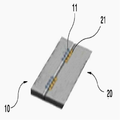
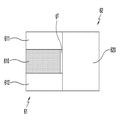
도 1은 본 발명의 다양한 실시예에 따른 제1,2하우징 부분이 자력결합된 전자 장치를 나타내는 도면이다.
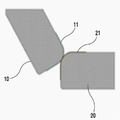
도 2는 본 발명의 다양한 실시예에 따른 제1,2하우징 부분이 각각 분리된 상태를 나타내는 도면이다.
도 3a는 본 발명의 다양한 실시예에 따른 제1,2하우징 부분의 언폴딩 상태를 나타내는 사시도이다.
도 3b는 본 발명의 다양한 실시예에 따른 제1,2하우징 부분의 언폴딩 상태를 나타내는 일부 측면도이다.
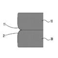
도 4는 본 발명의 다양한 실시예에 따른 제1,2하우징 부분의 폴딩 중 상태를 나타내는 일부 측면도이다.
도 5a는 본 발명의 다양한 실시예에 따른 제1,2하우징 부분의 폴딩 상태를 나타내는 사시도이다.
도 5b는 본 발명의 다양한 실시예에 따른 제1,2하우징 부분의 폴딩 상태를 나타내는 일부 측면도이다.
도 6은 본 발명의 다양한 실시예에 따른 제1하우징 부분에 채용되는 제1연결 부재의 구성을 나타내는 사시도이다.
도 7은 본 발명의 다양한 실시예에 따른 제1하우징 부분에 채용되는 제1연결 부재의 구성을 나타내는 평면도이다.
도 8은 본 발명의 다양한 실시예에 따른 제2하우징 부분에 채용되는 제2연결 부재의 구성을 나타내는 사시도이다.
도 9는 본 발명의 다양한 실시예에 따른 자력결합된 제1,2연결 부재의 배치 상태를 나타내는 평면도이다.
도 10은 본 발명의 다양한 실시예에 따른 샤프트에 장착된 4개의 제1연결 부재를 나타내는 사시도이다.
도 11은 본 발명의 다양한 실시예에 따른 샤프트와 제1금속체 간에 갭이 있는 상태를 나타내는 측면도이다.
도 12a는 본 발명의 다양한 실시예에 따른 제1하우징 부분에 채용되는 제1연결 부재를 나타내는 평면도이다.
도 12b는 본 발명의 다양한 실시예에 따른 자력결합된 제1,2연결 부재를 나타내는 평면도이다.
도 13은 본 발명의 다양한 실시예에 따른 제1,2하우징 부분이 자력결합된 언폴딩 상태의 장치를 나타내는 도면이다. BRIEF DESCRIPTION OF THE DRAWINGS Figure 1 is a diagram of an electronic device in which first and second housing portions are magnetically coupled in accordance with various embodiments of the present invention.
2 is a view showing a state in which the first and second housing parts are separated from each other according to various embodiments of the present invention.
3A is a perspective view showing an unfolded state of the first and second housing portions according to various embodiments of the present invention.
FIG. 3B is a partial side view illustrating the unfolded state of the first and second housing portions according to various embodiments of the present invention. FIG.
4 is a partial side view showing a folding state of the first and second housing portions according to various embodiments of the present invention.
5A is a perspective view illustrating folding states of first and second housing portions according to various embodiments of the present invention.
5B is a partial side view illustrating folding states of the first and second housing portions according to various embodiments of the present invention.
6 is a perspective view showing a configuration of a first connecting member employed in a first housing portion according to various embodiments of the present invention.
7 is a plan view showing a configuration of a first connecting member employed in a first housing portion according to various embodiments of the present invention.
8 is a perspective view showing a configuration of a second connecting member employed in a second housing portion according to various embodiments of the present invention.
9 is a plan view showing an arrangement of first and second magnetically coupled connecting members according to various embodiments of the present invention.
10 is a perspective view showing four first connecting members mounted on a shaft according to various embodiments of the present invention.
11 is a side view showing a gap between a shaft and a first metal body according to various embodiments of the present invention.
12A is a plan view showing a first connecting member employed in a first housing portion according to various embodiments of the present invention.
12B is a plan view showing first and second connection members magnetically coupled according to various embodiments of the present invention.
Figure 13 is a view of an unfolded device in which first and second housing portions are magnetically coupled according to various embodiments of the present invention.
이하, 본 개시의 다양한 실시예가 첨부된 도면을 참조하여 기재된다. 그러나, 이는 본 개시를 특정한 실시 형태에 대해 한정하려는 것이 아니며, 본 개시의 실시예의 다양한 변경(modification), 균등물(equivalent), 및/또는 대체물(alternative)을 포함하는 것으로 이해되어야 한다. 도면의 설명과 관련하여, 유사한 구성요소에 대해서는 유사한 참조 부호가 사용될 수 있다.Hereinafter, various embodiments of the present disclosure will be described with reference to the accompanying drawings. It should be understood, however, that this disclosure is not intended to limit the present disclosure to the particular embodiments, but includes various modifications, equivalents, and / or alternatives of the embodiments of the present disclosure. In connection with the description of the drawings, like reference numerals may be used for similar components.
본 문서에서, "가진다," "가질 수 있다,""포함한다," 또는 "포함할 수 있다" 등의 표현은 해당 특징(예:수치, 기능, 동작, 또는 부품 등의 구성요소)의 존재를 가리키며, 추가적인 특징의 존재를 배제하지 않는다.In this document, the expressions "having," " having, "" comprising," or &Quot;, and does not exclude the presence of additional features.
본 문서에서, "A 또는 B,""A 또는/및 B 중 적어도 하나,"또는 "A 또는/및 B 중 하나 또는 그 이상" 등의 표현은 함께 나열된 항목들의 모든 가능한 조합을 포함할 수 있다. 예를 들면, "A 또는 B," A 및 B 중 적어도 하나,"또는 " A 또는 B 중 적어도 하나"는, (1) 적어도 하나의 A를 포함, (2) 적어도 하나의 B를 포함, 또는 (3) 적어도 하나의 A 및 적어도 하나의 B 모두를 포함하는 경우를 모두 지칭할 수 있다.In this document, the expressions "A or B," "at least one of A or / and B," or "one or more of A and / or B," etc. may include all possible combinations of the listed items . For example, "A or B," "at least one of A and B," or "at least one of A or B" includes (1) at least one A, (2) at least one B, (3) at least one A and at least one B all together.
다양한 실시예에서 사용된 "제 1,""제 2,""첫째,"또는"둘째,"등의 표현들은 다양한 구성요소들을, 순서 및/또는 중요도에 상관없이 수식할 수 있고, 해당 구성요소들을 한정하지 않는다. 상기 표현들은 한 구성요소를 다른 구성요소와 구분하기 위해 사용될 수 있다. 예를 들면, 제1사용자 기기와 제2사용자 기기는, 순서 또는 중요도와 무관하게, 서로 다른 사용자 기기를 나타낼 수 있다. 예를 들면, 본 개시의 권리 범위를 벗어나지 않으면서 제 1 구성요소는 제 2 구성요소로 명명될 수 있고, 유사하게 제 2 구성요소도 제 1 구성요소로 바꾸어 명명될 수 있다.The terms "first," "second," "first," or "second," etc. used in various embodiments may describe various components in any order and / or importance, Lt; / RTI > The representations may be used to distinguish one component from another. For example, the first user equipment and the second user equipment may represent different user equipment, regardless of order or importance. For example, without departing from the scope of the present disclosure, the first component may be referred to as a second component, and similarly, the second component may be named as the first component.
어떤 구성요소(예: 제 1 구성요소)가 다른 구성요소(예: 제 2 구성요소)에 "(기능적으로 또는 통신적으로) 연결되어 ((operatively or communicatively) coupled with/to)" 있다거나, "접속되어 (connected to)" 있다고 언급된 때에는, 상기 어떤 구성요소가 상기 다른 구성요소에 직접적으로 연결되거나, 다른 구성요소(예:제 3 구성요소)를 통하여 연결될 수 있다고 이해되어야 할 것이다. 반면에, 어떤 구성요소 (예: 제 1 구성요소)가 다른 구성요소 (예: 제 2 구성요소)에 "직접 연결되어" 있다거나 "직접 접속되어" 있다고 언급된 때에는, 상기 어떤 구성요소와 상기 다른 구성요소 사이에 다른 구성요소(예: 제 3 구성요소)가 존재하지 않는 것으로 이해될 수 있다. It is also possible that a component (eg, a first component) is "(operatively or communicatively coupled) / to" another component (eg, a second component) It is to be understood that when an element is referred to as being "connected to ", it is to be understood that the element may be directly connected to the other element or may be connected through another element (e.g., a third element). On the other hand, when it is mentioned that a component (e.g., a first component) is "directly connected" or "directly connected" to another component (e.g., a second component) It can be understood that there is no other component (e.g., a third component) between other components.
본 문서에서 사용된 표현 "~하도록 구성된 (또는 설정된)(configured to)"은 상황에 따라, 예를 들면, "~에 적합한 (suitable for)," "하는 능력을 가지는 (having the capacity to)," "하도록 설계된 (designed to)," "하도록 변경된 (adapted to)," "~하도록 만들어진 (made to)," 또는 "~를 할 수 있는(capable of)"과 바꾸어 사용될 수 있다. 용어 "~하도록 구성 (또는 설정)된"은 하드웨어적으로 "특별히 설계된(specifically designed to) 것만 반드시 의미하지 않을 수 있다. 대신, 어떤 상황에서는, "~하도록 구성된 장치" 라는 표현은, 그 장치가 다른 장치 또는 부품들과 함께 "~할 수 있는"것을 의미할 수 있다. 예를 들면, 문구 A, B, 및 C를 수행하도록 구성(또는 설정)된 프로세서"는 해당 동작을 수행하기 위한 전용 프로세서(예: 임베디드 프로세서), 또는 메모리 장치에 저장된 하나 이상의 소프트웨어 프로그램들을 실행함으로써, 해당 동작들을 수행할 수 있는 범용 프로세서(generic-purpose processor)(예: CPU 또는 application processor)를 의미할 수 있다. The phrase " configured to " as used herein is intended to encompass, depending on the context, for example, having the ability to be suitable for, The present invention may be used interchangeably with "designed to," "adapted to," "made to," or "capable of". The term " configured to (or configured) "may not necessarily mean specifically designed to be" specifically designed. "Instead, in some circumstances, the expression" a device configured to " (Or set) to perform phrases A, B, and C. For example, a processor " configured (or configured) to perform phrases A, B, and C " (E. G., An embedded processor), or a generic-purpose processor (e. G., A CPU or application processor) capable of performing the operations by executing one or more software programs stored in the memory device.
본 문서에서 사용된 용어들은 단지 특정한 실시예를 설명하기 위해 사용된 것으로, 다른 실시예의 범위를 한정하려는 의도가 아닐 수 있다. 단수의 표현은 문맥상 명백하게 다르게 뜻하지 않는 한, 복수의 표현을 포함할 수 있다. 기술적이거나 과학적인 용어를 포함해서 여기서 사용되는 모든 용어들은 본 개시의 기술 분야에서 통상의 지식을 가진 자에 의해 일반적으로 이해되는 것과 동일한 의미를 가질 수 있다. 일반적으로 사용되는 사전에 정의된 용어들은 관련 기술의 문맥 상 가지는 의미와 동일 또는 유사한 의미를 가지는 것으로 해석될 수 있으며, 본 문서에서 명백하게 정의되지 않는 한, 이상적이거나 과도하게 형식적인 의미로 해석되지 않는다. 경우에 따라서, 본 문서에서 정의된 용어일지라도 본 개시의 실시예들을 배제하도록 해석될 수 없다.The terminology used herein is for the purpose of describing particular embodiments only and is not intended to limit the scope of the other embodiments. The singular expressions may include plural expressions unless the context clearly dictates otherwise. All terms used herein, including technical or scientific terms, may have the same meaning as commonly understood by one of ordinary skill in the art of the present disclosure. Commonly used predefined terms may be interpreted to have the same or similar meaning as the contextual meanings of the related art and are not to be construed as ideal or overly formal in meaning unless expressly defined in this document . In some cases, the terms defined herein may not be construed to exclude embodiments of the present disclosure.
이하에서는 첨부된 도면을 참조하여 본 발명의 다양한 실시예에 따른 장치의 구성에 대해서 설명하기로 한다. Hereinafter, a configuration of an apparatus according to various embodiments of the present invention will be described with reference to the accompanying drawings.
도 1은 본 발명의 다양한 실시예에 따른 제1,2 하우징 부분이 자력결합된 장치를 나타내는 도면이다. 도 2는 본 발명의 다양한 실시예에 따른 제1,2하우징 부분이 각각 분리된 상태를 나타내는 도면이다.1 is a view of an apparatus in which first and second housing portions are magnetically coupled according to various embodiments of the present invention. 2 is a view showing a state in which the first and second housing parts are separated from each other according to various embodiments of the present invention.
도 1, 도 2를 참조하면, 다양한 실시예에 따른 하우징 부분은 제1하우징 부분(10)과, 제2하우징 부분(20)과, 상기 제1,2하우징 부분(10,20)을 자력결합시키는 한 쌍의 연결 부재(11,21)를 포함할 수 있다. 상기 제1하우징 부분(10)에 실장되는 연결 부재를 제1연결 부재(11)라 지칭하고, 상기 제2하우징 부분(20)에 실장되는 연결 부재를 제2연결 부재(21)라 지칭할 수 있다. 후술하겠지만, 상기 제1,2연결 부재(11,21) 간의 자력결합으로, 상기 제1,2하우징 부분(10,20)은 일몸체로 결합될 수 있다. 다양한 실시예에 따른 장치는 비 삽입식으로 제1,2하우징 부분(10,20)이 결합될 수 있다. 또한, 다양한 실시예에 따른 장치는 면접촉식으로 제1,2하우징 부분(10,20)이 결합될 수 있다.1 and 2, a housing part according to various embodiments includes a
다양한 실시예에 따르면, 상기 제1,2연결 부재(11,21)는 자력 결합으로 일몸체로 결합될 수 있는데, 자력 결합은 서로 상극의 마그네트 성질을 이용하거나, 마그네트와 금속체를 이용하여 구현할 수 있다.According to various embodiments, the first and second connecting
다양한 실시예에 따르면, 상기 제1하우징 부분(10)의 제1결합부분의 제1결합면(10b)에 제1연결 부재(11)는 적어도 한 개 이상이나, 적어도 한 쌍 이상 실장될 수 있다. 상기 제1연결 부재(11)는 4개가 상측에, 4개가 하측에 각각 배치될 수 있다. 상기 제1결합면(10b) 상측에 배치된 4개의 제1연결 부재(11)를 제1상측 연결 부재(110)라 지칭할 수 있고, 상기 제1결합면(10b) 하측에 배치된 4개의 제1연결 부재(11)를 제1하측 연결 부재(112)라 지칭할 수 있다.According to various embodiments, at least one or more than one
다양한 실시예에 따르면, 상기 제2하우징 부분(20)의 제2결합부분의 제2결합면(20b)에 제2연결 부재(21)는 적어도 한 개 이상이나, 적어도 한 쌍 이상 실장될 수 있다. 상기 제2연결 부재(21)는 4개가 상측에, 4개가 하측에 각각 배치될 수 있다. 상기 제2결합면(20b) 상측에 배치된 4개의 제2연결 부재를 제2상측 연결 부재(210)라 지칭할 수 있고, 상기 제2결합면(20b) 하측에 배치된 4개의 제2연결 부재(21)를 제2하측 연결 부재(212)라 지칭할 수 있다.According to various embodiments, at least one or more than one
다양한 실시예에 따르면, 상기 제1상측 연결 부재(110)와, 제2상측 연결 부재(210)가 자력결합으로 연결될 수 있고, 상기 제1하측 연결 부재(112)와, 제2하측 연결 부재(212)가 자력결합으로 연결될 수 있다. According to various embodiments, the first upper linking member 110 and the second
다양한 실시예에 따르면, 상기 제1하우징 부분(10)은 제2하우징 부분(20)과 자력결합된 후, 자연스럽게 폴딩되거나 언폴딩되기 위해, 제1결합면(10b)을 가질 수 있다. 상기 제2하우징 부분(20)은 제1하우징 부분(10)과 자력결합된 후, 자연스럽게 폴딩되거나 언폴딩되기 위해, 제2결합면(20b)을 가질 수 있다. 상기 제1결합면(10b)은 소정의 제1곡률을 가지는 제1외주면을 구비할 수 있고, 상기 제2결합면920b)은 소정의 제1곡률을 가지는 제2외주면을 구비할 수 있다. According to various embodiments, the
이하에서는 다양한 실시예에 따른 장치의 폴딩/언폴딩 동작에 대해서 설명하기로 한다.Hereinafter, the folding / unfolding operation of the apparatus according to various embodiments will be described.
도 3a는 본 발명의 다양한 실시예에 따른 제1,2하우징 부분의 언폴딩 상태를 나타내는 사시도이다. 도 3b는 본 발명의 다양한 실시예에 따른 제1,2하우징 부분의 언폴딩 상태를 나타내는 일부 측면도이다.3A is a perspective view showing an unfolded state of the first and second housing portions according to various embodiments of the present invention. FIG. 3B is a partial side view illustrating the unfolded state of the first and second housing portions according to various embodiments of the present invention. FIG.
도 3a, 도 3b를 참조하면, 다양한 실시예에 따른 장치는 언폴딩 상태일 수 있다. 상기 제1,2하우징 부분(10,20)이 제1,2연결 부재(11,21)에 의해 자력결합된 후, 탁상 등에서 각각 수평한 상태로 배치될 수 있다. .Referring to FIGS. 3A and 3B, the apparatus according to various embodiments may be in an unfolded state. After the first and
도 4는 본 발명의 다양한 실시예에 따른 제1,2 장치의 폴딩 중 상태를 나타내는 일부 측면도이다.4 is a partial side view of a folding state of the first and second devices according to various embodiments of the present invention.
도 4를 참조하면, 다양한 실시예에 따른 하우징 부분은 제1,2결합면(10b,20b)의 면접촉에 따라서 폴딩 동작이 유연하게 진행될 수 있다. 상기 제1,2하우징 부분(10,20)이 제1,2연결 부재(11,21)에 의해 자력결합된 후, 상기 제2하우징 부분(20)을 폴딩할 수 있다. 상기 제1,2하우징 부분(10,20)의 폴딩된 상태가 도 5a, 도 5b에 도시되었다. Referring to FIG. 4, the folding operation of the housing part according to various embodiments can proceed flexibly according to the surface contact of the first and second coupling surfaces 10b and 20b. After the first and
도 6은 본 발명의 다양한 실시예에 따른 제1하우징 부분의 제1결합면에 실장되는 제1연결 부재를 나타내는 사시도이다. 도 7은 본 발명의 다양한 실시예에 따른 제1하우징 부분의 제1결합면에 실장되는 제1연결 부재를 나타내는 평면도이다.6 is a perspective view illustrating a first connecting member mounted on a first mating surface of a first housing portion according to various embodiments of the present invention. 7 is a plan view showing a first connecting member mounted on a first mating surface of a first housing portion according to various embodiments of the present invention;
도 6, 도 7을 참조하면, 다양한 실시예에 따른 제1연결 부재(31)는 마그네트(310)와, 마그네트(310) 양측에 각각 배치되는 제1금속체(311,312)를 포함할 수 있다. 상기 제1금속체(311,312)는 마그네트(310)에 자력에 의해 면접촉하게 실장되는데, 후술하겠지만, 샤프트에서 이동가능하게 실장될 수 있다. 상기 각각의 제1금속체(311,312)는 마그네트(310) 양측면에 각각 자력으로 면접촉하게 부착될 수 있다. 상기 마그네트(310)는 상하 평면(310a,310c)(평탄한 제1영역)과, 상기 상하 평면(310a,310c) 사이에 있는 외주면(310b)(제1영역으로부터 적어도 하나의 방향으로 휘어지도록 연장된 제2영역)을 구비할 수 있다. 상기 각각의 제1금속체(311,312)도 상하 평면(311a,311c;312a,312c))(평탄한 제1영역)과, 상기 상하 평면 사이에 있는 외주면(311b,312b)(제1영역으로부터 적어도 하나의 방향으로 휘어지도록 연장된 제2영역)을 구비할 수 있다. 상기 마그네트(310)의 외주면(310b)은 제1곡률을 가지는 곡면일 수 있다. 또한, 상기 각각의 제1금속체(311,312)의 곡면(311b,312b)도 제1곡률을 가지는 곡면일 수 있다. 상기 마그네트(310) 및 제1금속체(311,312)는 샤프트가 관통하기 위한 관통홀이 각각 형성될 수 있다. 도면에는 하나의 제1금속체(312))에 형성된 관통홀(312d)만이 보여진다.6 and 7, the first connecting
도 8은 본 발명의 다양한 실시예에 따른 제2하우징 부분에 채용되는 제2연결 부재의 구성을 나타내는 사시도이다.8 is a perspective view showing a configuration of a second connecting member employed in a second housing portion according to various embodiments of the present invention.
도 8을 참조하면, 다양한 실시예에 따른 제2연결 부재(32)는 상하 평면(320a,320c)과, 상기 상하 평면(320a,320c) 사이에 있는 외주면(320b)을 구비할 수 있다. 상기 외주면(320b)은 제1곡률을 가지는 곡면일 수 있다. Referring to FIG. 8, the
도 9는 본 발명의 다양한 실시예에 따른 자력결합된 제1,2연결 부재의 배치 상태를 나타내는 평면도이다.9 is a plan view showing an arrangement of first and second magnetically coupled connecting members according to various embodiments of the present invention.
도 9를 참조하면, 본 발명의 다양한 실시예에 따른 제1,2하우징 부분(40,50)에 각각 채용되는 제1,2연결 부재(41,51)는 각각 제1,2하우징 부분의 제1,2결합면(40a,50a)에 장착되어, 서로 자력결합될 수 있다.Referring to FIG. 9, the first and second connecting
다양한 실시예에 따르면, 상기 제1연결 부재(41)는 4개가 나란하게 등간격으로 배치되어, 상측 제1연결 부재를 구성할 수 있다. 상기 제2연결 부재(51)는 4개가 나란하게 등간격으로 배치되어, 상측 제2연결 부재를 구성할 수 있다. 동일하게 상기 제1연결 부재(41)는 4개가 나란하게 등간격으로 배치되어, 하측 제1연결 부재를 구성할 수 있다. 상기 제2연결 부재(51)는 4개가 나란하게 등간격으로 배치되어, 하측 제2연결 부재를 구성할 수 있다.According to various embodiments, the
다양한 실시예에 따르면, 상기 각각의 제1,2연결 부재(41,51)는 서로 마주보면서, 면접촉으로 폴딩/언폴딩 동작을 수행할 수 있다. 이 때, 상기 제1연결 부재(41)는 하나의 마그네트(410)에 두 개의 제1금속체(411,412)가 구비되어, 상기 제2연결 부재(51)와 접촉동작을 할 수 있다.According to various embodiments, the first and second connecting
또 다른 예로, 상기 제1연결 부재(41)는 마그네트(410)의 양 측면에 제1금속체(411,412)가 각각 배열되는 것이 바람직한데, 이 때, 상기 각각의 제1금속체(411,412)는 마그네트(410)보다 큰 면적을 가지고, 샤프트에 대해 약간의 이격을 가지도록 구성(도 11 참조)될 수 있다. As another example, it is preferable that the first connecting
또 다른 예로, 상기 제1금속체(411,412)는 마그네트(410)의 양면을 차폐하는 기능을 제공하여 누설 자기가 장치에 악영향을 미치는 것을 미연에 방지할 수 있다.As another example, the
도 10은 본 발명의 다양한 실시예에 따른 샤프트에 장착된 4개의 제1연결 부재를 나타내는 사시도이다. 도 11은 본 발명의 다양한 실시예에 따른 샤프트와 제1금속체 간에 갭이 있는 상태를 나타내는 측면도이다. 10 is a perspective view showing four first connecting members mounted on a shaft according to various embodiments of the present invention. 11 is a side view showing a gap between a shaft and a first metal body according to various embodiments of the present invention.
도 10, 도 11을 참조하면, 다양한 실시예에 따른 제1연결 부재(41)는 샤프트(420)에 의해 4개가 하나의 조립체로 결합되어 제1하우징 부분의 상측과 하측에 장착될 수 있다. 상기 하나의 제1연결 부재(41)는 마그네트(410)와, 상기 마그네트(410) 양 측면에 배치된 한 쌍의 제1금속체(411,412)를 포함할 수 있다. 상기 각각의 제1금속체(411,412)는 자력에 의해 상기 마그네트(410) 양 측면에 각각 면대면(face-to-face)으로 접촉하게 배치될 수 있다. Referring to FIGS. 10 and 11, the first connecting
상기 샤프트(420)에 마그네트(410)만이 등간격으로 고정되고, 상기 각각의 제1금속체(411,412)는 고정되지 않고, 상기 샤프트(420)에서 이동가능하게 장착될 수 있다. 상기 샤프트(420) 외주면과 상기 각각의 제1금속체(411,412)에 구비된 샤프트 관통홀(411d,412d)과는 갭(g)이 존재할 수 있다. 즉, 상기 사프트(420) 외경 크기보다 상기 관통홀(411d,412d) 외경 크기를 더 크게 구성하여서, 상기 제1금속체(411,412)는 이동 공간이 존재할 수 있다. 상기 제1금속체(411,412)를 샤프트(420)에 고정하지 않고, 이동가능하게 배치하는 이유는 제2연결 부재의 금속체에 신속하고, 안정적으로 접속되기 위함이다. 상기 각각의 제1금속체(411,412)는 마그네트(410)와 결합된 상태에서, 각각의 단부에 자력이 집중되는 성질(단부가 자속 밀도가 높음)에 의해, 상기 제2연결 부재의 금속체에 보다 안정적으로 자력으로 신속하게 어느 하나의 금속체가 결합될 수 있다. Only the
상기 제1연결 부재(41)는 4개가 하나의 사프트(420)에 조립되어 상측 제1연결 부재를 구성할 수 있다. The
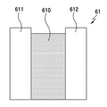
도 12a는 본 발명의 다양한 실시예에 따른 제1 장치에 채용되는 제1연결 부재를 나타내는 평면도이다.12A is a plan view showing a first connecting member employed in a first apparatus according to various embodiments of the present invention.
도 12a를 참조하면, 다양한 실시예에 따른 제1연결 부재(61)는 각각 마그네트(610)와, 상기 마그네트(610) 양 측면에 각각 배치되는 한 쌍의 제1금속체(611,612)를 포함할 수 있다. 이 때, 상기 제1금속체(611,612)에 비해서 상기 마그네트(610)는 약간 작은 사이즈로 구성될 수 있다. 즉, 상기 제1연결 부재의 외관을 보면, 상기 각각의 제1금속체(611,612)에 비해서, 상기 마그네트(610)는 단차진 형상(615)(stepped portion)으로 배치될 수 있다. 12A, the first connecting
도 12b는 본 발명의 다양한 실시예에 따른 자력결합된 제1,2연결 부재를 나타내는 평면도이다.12B is a plan view showing first and second connection members magnetically coupled according to various embodiments of the present invention.
도 12b를 참조하면, 상기 제1연결 부재(61)가 제2연결 부재(62)와 자력결합되면, 상기 마그네트(610) 외면과, 상기 제2연결 부재의 금속체(620) 외면 간에는 갭이 존재할 수 있다. 상기 제1,2연결 부재(61,62)는 항시 외부에 노출될 수 있기 때문에, 이물질이 항시 있을 수 있다. 상기 이물질에 의해 상기 제1,2연결 부재(61,62)의 결합이 원할하지 않을 수 있다. 상기 갭(g1)에 이물질이 도피할 수 있는 공간을 제공하여, 보다 안정적으로 상기 제1,2연결 부재(61,62) 간의 자력 결합이 구성될 수 있다.12B, when the first connecting
도 13은 본 발명의 다양한 실시예에 따른 제1,2하우징 부분이 자력결합된 언폴딩 상태의 장치를 나타내는 도면이다. Figure 13 is a view of an unfolded device in which first and second housing portions are magnetically coupled according to various embodiments of the present invention.
도 13을 참조하면, 본 발명의 다양한 실시예에 따른 장치는 제1,2하우징 부분(70,72)이 제1,2연결 부재(71,73)의 자력 결합 시에 결합 위치를 잡아주기 위한 홀딩 장치(74,75)를 구비할 수 있다. 상기 홀딩 장치(74,75)는 마그네트의 극성을 이용하여 구현될 수 있다. 상기 제1,2하우징 부분(70,72)의 결합 위치를 잡아주는 홀딩 장치(74,75)는 제1하우징 부분(70)에 배치되는 적어도 하나 이상의 제1마그네트(74)와, 상기 제2하우징 부분(72)에 배치되는 적어도 하나 이상의 제2마그네트(75)를 포함할 수 있다. 상기 제1마그네트(74)는 제1극성을 가지며, 상기 제1하우징 부분(70)의 제1결합면을 따라서 복수 개가 배치될 수 있다. 상기 제1마그네트(74)의 하나는 상기 제1연결 부재(71) 사이 사이에 배치될 수 있다. 상기 제2마그네트(75)는 상기 제1극성과는 반대의 제2극성을 가지며, 상기 제2하우징 부분(72)의 제2결합면을 따라서 복수 개가 배치될 수 있다. 상기 제2마그네트(75)는 상기 제2연결 부재(73) 사이사이에 배치될 수 있다. 상기 각각의 제1,2마그네트(74,75)는 대응하는 위치에, 어느 정도 거리 이내에 배치될 수 있다. 상기 제1,2마그네트(74,75)들의 자력 결합 시, 상기 제1연결 부재와 제2연결 부재가 정확한 위치를 가지면서 상호 간 자력 결합되도록 하여, 역방향 접점을 방지할 수 있다.Referring to FIG. 13, the apparatus according to various embodiments of the present invention includes a
그리고, 본 명세서와 도면에 개시된 본 개시의 다양한 실시예들은 본 개시의 기술 내용을 쉽게 설명하고 본 개시의 이해를 돕기 위해 특정 예를 제시한 것일 뿐이며, 본 개시의 범위를 한정하고자 하는 것은 아니다. 따라서 본 개시의 범위는 여기에 개시된 실시 예들 이외에도 본 개시의 기술적 사상을 바탕으로 도출되는 모든 변경 또는 변형된 형태가 본 개시의 범위에 포함되는 것으로 해석되어야 한다.It is to be understood that the various embodiments of the present disclosure disclosed in this specification and the drawings are only illustrative of specific examples in order to facilitate describing the subject matter of the disclosure and to facilitate understanding of the disclosure, and are not intended to limit the scope of the disclosure. Accordingly, the scope of the present disclosure should be construed as being included within the scope of the present disclosure in addition to the embodiments disclosed herein, all changes or modifications derived from the technical idea of the present disclosure.
Claims (18)
제1하우징 부분(a first housing part);
상기 제1하우징 부분에 포함된 제1연결 부재;
제2하우징 부분; 및
상기 제2하우징 부분에 포함된 제2연결 부재를 포함하고,
상기 제1 또는 제2연결부재 중 적어도 하나는 자성체 또는 자력에 의해 끌리는 물질을 포함하고,
상기 제1 또는 제2연결부재, 및 상기 제1 또는 제2하우징 부분 중 상기 제1 또는 제2연결부재와 인접한 부분은, 편평한 제 1 영역, 및 상기 제 1 영역으로부터 적어도 하나의 방향으로 휘어지도록 연장된 제 2 영역을 포함하고,
상기 제1 및 제2하우징 부분은 상기 제1 및 제2연결부재의 자력에 의한 결합을 통하여 서로 결합 가능하도록 구성된 장치.In the apparatus,
A first housing part;
A first connecting member included in the first housing portion;
A second housing portion; And
And a second connecting member included in the second housing portion,
Wherein at least one of the first and second connection members includes a magnetic substance or a material attracted by a magnetic force,
Wherein the first or second connecting member and a portion of the first or second housing portion adjacent to the first or second connecting member are formed to have a flat first region and a second region extending from the first region in at least one direction An extended second region,
Wherein the first and second housing portions are capable of engaging with each other through a coupling by the magnetic forces of the first and second connecting members.
마그네트; 및
상기 마그네트의 일측 또는 양 측에 각각 구성되는 제1금속체를 포함하는 장치.2. The apparatus according to claim 1, wherein the first connecting member
Magnet; And
And a first metal body each formed on one side or both sides of the magnet.
상기 제1곡률 중심을 따라 제1하우징 부분에 배치되는 샤프트;
상기 샤프트를 관통하게 실장되는 마그네트; 및
상기 샤프트를 관통하게 실장되되, 상기 마그네트 양측에 각각 대면하게 자력결합되는 제1,2금속체를 포함하는 장치.6. The connector according to claim 5, wherein the first connecting member
A shaft disposed in the first housing portion along the first curvature center;
A magnet mounted through the shaft; And
And first and second metal bodies mounted to penetrate the shaft and magnetically coupled to both sides of the magnet respectively.
상기 제1마그네트는 제1하우징 부분의 결합면을 따라서 적어도 하나 이상 배치되고, 상기 제2마그네트는 제2하우징 부분의 결합면을 따라서 적어도 하나 이상 배치되는 장치.18. The apparatus of claim 17, wherein the holding device comprises: a first magnet disposed in a first housing portion; and a second magnet disposed in the second housing portion, the second magnet being in phase with the first magnet,
Wherein the first magnet is disposed along at least one engagement surface of the first housing portion and the second magnet is disposed along at least one engagement surface of the second housing portion.
Priority Applications (2)
| Application Number | Priority Date | Filing Date | Title |
|---|---|---|---|
| KR1020150161844A KR20170058081A (en) | 2015-11-18 | 2015-11-18 | Eletronic device with magnet-connected |
| US15/214,157 US10036186B2 (en) | 2015-11-18 | 2016-07-19 | Electronic device and magnetic connection thereof |
Applications Claiming Priority (1)
| Application Number | Priority Date | Filing Date | Title |
|---|---|---|---|
| KR1020150161844A KR20170058081A (en) | 2015-11-18 | 2015-11-18 | Eletronic device with magnet-connected |
Publications (1)
| Publication Number | Publication Date |
|---|---|
| KR20170058081A true KR20170058081A (en) | 2017-05-26 |
Family
ID=58690897
Family Applications (1)
| Application Number | Title | Priority Date | Filing Date |
|---|---|---|---|
| KR1020150161844A KR20170058081A (en) | 2015-11-18 | 2015-11-18 | Eletronic device with magnet-connected |
Country Status (2)
| Country | Link |
|---|---|
| US (1) | US10036186B2 (en) |
| KR (1) | KR20170058081A (en) |
Cited By (1)
| Publication number | Priority date | Publication date | Assignee | Title |
|---|---|---|---|---|
| WO2021245628A1 (en) * | 2019-06-07 | 2021-12-09 | Filippo Gioco | Attaching screen protectors to mobile devices, tablets, and computers |
Families Citing this family (4)
| Publication number | Priority date | Publication date | Assignee | Title |
|---|---|---|---|---|
| USD804928S1 (en) * | 2016-05-27 | 2017-12-12 | Ideal Sanitary Ware Co., Ltd. | Hinge |
| US10330134B2 (en) | 2017-03-12 | 2019-06-25 | Peter Joseph Danko | Modular panel structure having magnetic hinge joint |
| KR102373875B1 (en) * | 2017-05-22 | 2022-03-14 | 삼성전자주식회사 | Electronic device with multi-angle cradling |
| EP3804828B1 (en) * | 2018-05-31 | 2023-08-09 | Zeon Corporation | Connection unit |
Family Cites Families (15)
| Publication number | Priority date | Publication date | Assignee | Title |
|---|---|---|---|---|
| KR100402793B1 (en) | 2001-08-23 | 2003-10-22 | 삼성전자주식회사 | Portable terminal having a keyboard |
| KR200269980Y1 (en) | 2001-12-24 | 2002-03-25 | 고상철 | Wireless internet key board device |
| US7252512B2 (en) * | 2004-04-21 | 2007-08-07 | Japan Aviation Electronics Industry, Limited | Self-alignment magnetic connector reduced in size |
| US7583500B2 (en) * | 2005-12-13 | 2009-09-01 | Apple Inc. | Electronic device having magnetic latching mechanism |
| JP2008165367A (en) * | 2006-12-27 | 2008-07-17 | Toshiba Corp | Electronic device |
| KR100938035B1 (en) | 2008-06-02 | 2010-01-21 | 유상규 | Swing type foldable keyboard for portable computer |
| CN101672322B (en) * | 2008-09-10 | 2012-06-20 | 鸿富锦精密工业(深圳)有限公司 | Magnetic hinge structure |
| KR20100125968A (en) | 2009-05-22 | 2010-12-01 | 강동연 | A portable keyboard |
| US9335793B2 (en) | 2011-01-31 | 2016-05-10 | Apple Inc. | Cover attachment with flexible display |
| US8907752B2 (en) * | 2011-09-12 | 2014-12-09 | Justin Richard Wodrich | Integrated inductive charging in protective cover |
| US9460029B2 (en) * | 2012-03-02 | 2016-10-04 | Microsoft Technology Licensing, Llc | Pressure sensitive keys |
| US9559456B2 (en) * | 2013-03-15 | 2017-01-31 | Google Technology Holdings LLC | Magnetic electrical connection system for an electronic device |
| DE102015116490A1 (en) * | 2014-11-19 | 2016-05-19 | Rosenberger Hochfrequenztechnik Gmbh & Co. Kg | Magnetic connection device |
| US9774136B2 (en) * | 2015-12-02 | 2017-09-26 | Nanoport Technology Inc. | Self-aligning connector |
| US20170257146A1 (en) * | 2016-03-01 | 2017-09-07 | Nanoport Technology Inc. | Facilitating alignment of wireless elements for ultra short range wireless interaction |
-
2015
- 2015-11-18 KR KR1020150161844A patent/KR20170058081A/en not_active IP Right Cessation
-
2016
- 2016-07-19 US US15/214,157 patent/US10036186B2/en active Active
Cited By (1)
| Publication number | Priority date | Publication date | Assignee | Title |
|---|---|---|---|---|
| WO2021245628A1 (en) * | 2019-06-07 | 2021-12-09 | Filippo Gioco | Attaching screen protectors to mobile devices, tablets, and computers |
Also Published As
| Publication number | Publication date |
|---|---|
| US20170138101A1 (en) | 2017-05-18 |
| US10036186B2 (en) | 2018-07-31 |
Similar Documents
| Publication | Publication Date | Title |
|---|---|---|
| KR20170058081A (en) | Eletronic device with magnet-connected | |
| US9461425B2 (en) | Connector with easily positionable parts | |
| JP6701344B2 (en) | Folding terminal | |
| JP6103917B2 (en) | Electrical connector assembly | |
| JP5413925B2 (en) | Magnetic lock | |
| US9837745B2 (en) | Connector terminal with one or more top side contact portions and three linear bottom side contact portions | |
| KR20170011973A (en) | Mobile device | |
| CN102774230B (en) | Equipotential electricity mural painting equipment | |
| EP1776887A3 (en) | Side-release buckle assembly | |
| US20150017823A1 (en) | Connector | |
| JP2006066305A (en) | Spring connector | |
| JP2021002462A5 (en) | ||
| JP6858949B2 (en) | Contacts, connector members and connectors | |
| TWM463924U (en) | Fastening sleeve of connector | |
| KR101747054B1 (en) | Locking apparatus for plug connectors | |
| KR20170117693A (en) | Connector | |
| US20160146221A1 (en) | Fan assembly | |
| JP5872970B2 (en) | Connector terminal and connection structure between this connector terminal and mating terminal | |
| JP2011027214A (en) | Fastener | |
| KR101321844B1 (en) | Metal pin connector having lamella contact structure | |
| JP5066623B2 (en) | Waterproof connector assembly | |
| JP2017091660A (en) | Lock structure of connector assembly | |
| CN107581810B (en) | Furniture assembly and vibration arrangement for detecting for knockdown furniture part | |
| JP5905713B2 (en) | Snap fit | |
| JP5717292B2 (en) | Conductor connector |
Legal Events
| Date | Code | Title | Description |
|---|---|---|---|
| SUBM | Surrender of laid-open application requested |