KR20170054708A - Multi-Coil Wireless Charging Method and Apparatus and System therefor - Google Patents
Multi-Coil Wireless Charging Method and Apparatus and System therefor Download PDFInfo
- Publication number
- KR20170054708A KR20170054708A KR1020150157197A KR20150157197A KR20170054708A KR 20170054708 A KR20170054708 A KR 20170054708A KR 1020150157197 A KR1020150157197 A KR 1020150157197A KR 20150157197 A KR20150157197 A KR 20150157197A KR 20170054708 A KR20170054708 A KR 20170054708A
- Authority
- KR
- South Korea
- Prior art keywords
- wireless power
- transmission
- signal
- sensing signal
- coil
- Prior art date
Links
- 238000000034 method Methods 0.000 title claims abstract description 145
- 230000005540 biological transmission Effects 0.000 claims abstract description 329
- 238000004891 communication Methods 0.000 claims description 21
- 230000004044 response Effects 0.000 claims description 12
- 238000001514 detection method Methods 0.000 abstract description 53
- 230000008901 benefit Effects 0.000 abstract description 7
- 230000008054 signal transmission Effects 0.000 description 56
- 238000010586 diagram Methods 0.000 description 26
- 230000007704 transition Effects 0.000 description 19
- 238000012546 transfer Methods 0.000 description 16
- 238000006243 chemical reaction Methods 0.000 description 13
- 238000005516 engineering process Methods 0.000 description 10
- 230000005674 electromagnetic induction Effects 0.000 description 6
- 230000008859 change Effects 0.000 description 5
- 230000006698 induction Effects 0.000 description 4
- 230000008569 process Effects 0.000 description 4
- 230000007480 spreading Effects 0.000 description 4
- 230000000694 effects Effects 0.000 description 3
- 238000009774 resonance method Methods 0.000 description 3
- 238000012937 correction Methods 0.000 description 2
- 230000010363 phase shift Effects 0.000 description 2
- 239000003990 capacitor Substances 0.000 description 1
- 238000007796 conventional method Methods 0.000 description 1
- 238000013500 data storage Methods 0.000 description 1
- 230000005684 electric field Effects 0.000 description 1
- 230000005611 electricity Effects 0.000 description 1
- 230000004907 flux Effects 0.000 description 1
- 230000000977 initiatory effect Effects 0.000 description 1
- 230000003287 optical effect Effects 0.000 description 1
- 230000001151 other effect Effects 0.000 description 1
- 239000002699 waste material Substances 0.000 description 1
Images


Classifications
-
- H—ELECTRICITY
- H02—GENERATION; CONVERSION OR DISTRIBUTION OF ELECTRIC POWER
- H02J—CIRCUIT ARRANGEMENTS OR SYSTEMS FOR SUPPLYING OR DISTRIBUTING ELECTRIC POWER; SYSTEMS FOR STORING ELECTRIC ENERGY
- H02J50/00—Circuit arrangements or systems for wireless supply or distribution of electric power
- H02J50/40—Circuit arrangements or systems for wireless supply or distribution of electric power using two or more transmitting or receiving devices
- H02J50/402—Circuit arrangements or systems for wireless supply or distribution of electric power using two or more transmitting or receiving devices the two or more transmitting or the two or more receiving devices being integrated in the same unit, e.g. power mats with several coils or antennas with several sub-antennas
-
- H02J7/025—
-
- H—ELECTRICITY
- H01—ELECTRIC ELEMENTS
- H01F—MAGNETS; INDUCTANCES; TRANSFORMERS; SELECTION OF MATERIALS FOR THEIR MAGNETIC PROPERTIES
- H01F38/00—Adaptations of transformers or inductances for specific applications or functions
- H01F38/14—Inductive couplings
-
- H02J17/00—
-
- H—ELECTRICITY
- H02—GENERATION; CONVERSION OR DISTRIBUTION OF ELECTRIC POWER
- H02J—CIRCUIT ARRANGEMENTS OR SYSTEMS FOR SUPPLYING OR DISTRIBUTING ELECTRIC POWER; SYSTEMS FOR STORING ELECTRIC ENERGY
- H02J50/00—Circuit arrangements or systems for wireless supply or distribution of electric power
- H02J50/10—Circuit arrangements or systems for wireless supply or distribution of electric power using inductive coupling
- H02J50/12—Circuit arrangements or systems for wireless supply or distribution of electric power using inductive coupling of the resonant type
-
- H—ELECTRICITY
- H02—GENERATION; CONVERSION OR DISTRIBUTION OF ELECTRIC POWER
- H02J—CIRCUIT ARRANGEMENTS OR SYSTEMS FOR SUPPLYING OR DISTRIBUTING ELECTRIC POWER; SYSTEMS FOR STORING ELECTRIC ENERGY
- H02J50/00—Circuit arrangements or systems for wireless supply or distribution of electric power
- H02J50/80—Circuit arrangements or systems for wireless supply or distribution of electric power involving the exchange of data, concerning supply or distribution of electric power, between transmitting devices and receiving devices
-
- H—ELECTRICITY
- H02—GENERATION; CONVERSION OR DISTRIBUTION OF ELECTRIC POWER
- H02J—CIRCUIT ARRANGEMENTS OR SYSTEMS FOR SUPPLYING OR DISTRIBUTING ELECTRIC POWER; SYSTEMS FOR STORING ELECTRIC ENERGY
- H02J50/00—Circuit arrangements or systems for wireless supply or distribution of electric power
- H02J50/90—Circuit arrangements or systems for wireless supply or distribution of electric power involving detection or optimisation of position, e.g. alignment
-
- H—ELECTRICITY
- H02—GENERATION; CONVERSION OR DISTRIBUTION OF ELECTRIC POWER
- H02J—CIRCUIT ARRANGEMENTS OR SYSTEMS FOR SUPPLYING OR DISTRIBUTING ELECTRIC POWER; SYSTEMS FOR STORING ELECTRIC ENERGY
- H02J7/00—Circuit arrangements for charging or depolarising batteries or for supplying loads from batteries
- H02J7/02—Circuit arrangements for charging or depolarising batteries or for supplying loads from batteries for charging batteries from ac mains by converters
-
- H—ELECTRICITY
- H04—ELECTRIC COMMUNICATION TECHNIQUE
- H04B—TRANSMISSION
- H04B5/00—Near-field transmission systems, e.g. inductive or capacitive transmission systems
-
- H04B5/0037—
Landscapes
- Engineering & Computer Science (AREA)
- Power Engineering (AREA)
- Computer Networks & Wireless Communication (AREA)
- Signal Processing (AREA)
- Charge And Discharge Circuits For Batteries Or The Like (AREA)
Abstract
Description
본 발명은 무선 전력 전송 기술에 관한 것으로서, 상세하게, 복수의 송신 코일이 탑재된 무선 전력 송신기에서의 무선 전력 수신기의 인식 시간을 최소화시키기 위한 멀티 코일 무선 충전 방법 및 그를 위한 장치 및 시스템에 관한 것이다.The present invention relates to a wireless power transmission technique, and more particularly, to a multi-coil wireless charging method and apparatus and system therefor, in order to minimize the recognition time of a wireless power receiver in a wireless power transmitter equipped with a plurality of transmission coils .
최근 정보 통신 기술이 급속도로 발전함에 따라, 정보 통신 기술을 기반으로 하는 유비쿼터스 사회가 이루어지고 있다.Recently, as the information and communication technology rapidly develops, a ubiquitous society based on information and communication technology is being made.
언제 어디서나 정보통신 기기들이 접속되기 위해서는 사회 모든 시설에 통신 기능을 가진 컴퓨터 칩을 내장시킨 센서들이 설치되어야 한다. 따라서 이들 기기나 센서의 전원 공급 문제는 새로운 과제가 되고 있다. 또한 휴대폰뿐만 아니라 블루투스 핸드셋과 아이팟 같은 뮤직 플레이어 등의 휴대기기 종류가 급격히 늘어나면서 배터리를 충전하는 작업이 사용자에게 시간과 수고를 요구하고 됐다. 이러한 문제를 해결하는 방법으로 무선 전력 전송 기술이 최근 들어 관심을 받고 있다. In order for information communication devices to be connected anytime and anywhere, sensors equipped with a computer chip having a communication function must be installed in all facilities of the society. Therefore, power supply problems of these devices and sensors are becoming a new challenge. In addition, mobile devices such as Bluetooth handsets and iPods, as well as mobile phones, have been rapidly increasing in number, and charging the battery has required users time and effort. As a way to solve this problem, wireless power transmission technology has recently attracted attention.
무선 전력 전송 기술(wireless power transmission 또는 wireless energy transfer)은 자기장의 유도 원리를 이용하여 무선으로 송신기에서 수신기로 전기 에너지를 전송하는 기술로서, 이미 1800년대에 전자기유도 원리를 이용한 전기 모터나 변압기가 사용되기 시작했고, 그 후로는 라디오파나 레이저, 고주파, 마이크로웨이브와 같은 전자파를 방사해서 전기에너지를 전송하는 방법도 시도되었다. 우리가 흔히 사용하는 전동칫솔이나 일부 무선면도기도 실상은 전자기유도 원리로 충전된다. The wireless power transmission technology (wireless power transmission or wireless energy transfer) is a technology to transmit electric energy from the transmitter to the receiver wirelessly using the induction principle of the magnetic field. In the 1800s, electric motor or transformer And thereafter, a method of radiating electromagnetic waves such as radio waves, lasers, high frequencies, and microwaves to transfer electrical energy has also been attempted. Our electric toothbrushes and some wireless shavers are actually charged with electromagnetic induction.
현재까지 무선을 이용한 에너지 전달 방식은 크게 자기 유도 방식, 자기 공진(Electromagnetic Resonance) 방식 및 단파장 무선 주파수를 이용한 RF 전송 방식 등으로 구분될 수 있다.Up to the present, energy transmission using radio may be roughly classified into a magnetic induction method, an electromagnetic resonance method, and an RF transmission method using a short wavelength radio frequency.
자기 유도 방식은 두 개의 코일을 서로 인접시킨 후 한 개의 코일에 전류를 흘려보내면 이 때 발생한 자속(MagneticFlux)이 다른 코일에 기전력을 일으키는 현상을 사용한 기술로서, 휴대폰과 같은 소형기기를 중심으로 빠르게 상용화가 진행되고 있다. 자기 유도 방식은 최대 수백 키로와트(kW)의 전력을 전송할 수 있고 효율도 높지만 최대 전송 거리가 1센티미터(cm) 이하이므로 일반적으로 충전기나 바닥에 인접시켜야 하는 단점이 있다.In the magnetic induction method, when two coils are adjacent to each other and a current is supplied to one coil, a magnetic flux generated at this time causes an electromotive force to the other coils. As a technology, . The magnetic induction method has the disadvantage that it can transmit power of up to several hundred kilowatts (kW) and the efficiency is high, but the maximum transmission distance is 1 centimeter (cm) or less, so it is usually adjacent to the charger or the floor.
자기 공진 방식은 전자기파나 전류 등을 활용하는 대신 전기장이나 자기장을 이용하는 특징이 있다. 자기 공진 방식은 전자파 문제의 영향을 거의 받지 않으므로 다른 전자 기기나 인체에 안전하다는 장점이 있다. 반면, 한정된 거리와 공간에서만 활용할 수 있으며 에너지 전달 효율이 다소 낮다는 단점이 있다.The self-resonance method is characterized by using an electric field or a magnetic field instead of using electromagnetic waves or currents. The self-resonance method is advantageous in that it is safe to other electronic devices or human body since it is hardly influenced by the electromagnetic wave problem. On the other hand, it can be used only at a limited distance and space, and has a disadvantage that energy transfer efficiency is somewhat low.
단파장 무선 전력 전송 방식-간단히, RF 전송 방식-은 에너지가 라디오 파(RadioWave)형태로 직접 송수신될 수 있다는 점을 활용한 것이다. 이 기술은 렉테나(rectenna)를 이용하는 RF 방식의 무선 전력 전송 방식으로서, 렉테나는 안테나(antenna)와 정류기(rectifier)의 합성어로서 RF 전력을 직접 직류 전력으로 변환하는 소자를 의미한다. 즉, RF 방식은 AC 라디오파를 DC로 변환하여 사용하는 기술로서, 최근 효율이 향상되면서 상용화에 대한 연구가 활발히 진행되고 있다.Short wavelength wireless power transmission - simply, RF transmission - takes advantage of the fact that energy can be transmitted and received directly in radio wave form. This technology is a RF power transmission system using a rectenna. Rectena is a combination of an antenna and a rectifier, which means a device that converts RF power directly into direct current power. That is, the RF method is a technique of converting an AC radio wave into DC and using it. Recently, as the efficiency has improved, commercialization has been actively researched.
무선 전력 전송 기술은 모바일 뿐만 아니라 IT, 철도, 가전 산업 등 산업 전반에 다양하게 활용될 수 있다.Wireless power transmission technology can be applied not only to mobile, but also to various industries such as IT, railroad, and household appliance industry.
최근에는 충전 베드에 놓여진 무선 전력 수신기의 인식률을 높이기 위해 복수의 코일이 장착된 무선 전력 송신기가 출시되고 있다. 하지만, 종래의 복수의 코일이 장착된 무선 전력 송신기는 무선 전력 수신기의 존재를 감지하기 위해 각각의 송신 코일을 통해 순차적으로 감지 신호-예를 들면, 전자기 유도 방식에 사용되는 핑 신호, 전자기 공진 방식에 사용되는 비콘 신호 등을 포함함- 송출하였다. Recently, a wireless power transmitter with a plurality of coils has been introduced to increase the recognition rate of a wireless power receiver placed on a charging bed. However, in a conventional wireless power transmitter equipped with a plurality of coils, it is necessary to sequentially detect signals through respective transmission coils in order to detect the presence of the wireless power receiver, for example, a ping signal used for an electromagnetic induction system, And a beacon signal used in the system.
특히, 종래의 복수의 송신 코일이 장착된 무선 전력 송신기는 도 1에 도시된 바와 같이, 무선 전력 수신기에 대한 인식 오류를 줄이고, 어떤 송신 코일이 충전 효율이 좋은지를 결정하기 위해 감지 신호를 순차적으로 소정 회수-예를 들면, 2회- 반복하여 각각의 송신 코일을 통해 송출하도록 제어하였다. In particular, a wireless power transmitter with a plurality of conventional transmit coils is configured to reduce the recognition error for the wireless power receiver, and to sequentially determine the transmit power of the transmit coil, as shown in FIG. 1, For example, two times - repeatedly so as to be transmitted through each of the transmission coils.
하지만, 각각의 송신 코일에서 순차적으로 감지 신호를 소정 회수 반복 송출하는 방법은 미리 설정된 감지 신호 송출 절차가 모두 완료된 후 무선 전력 수신기를 위해 사용될 송신 코일이 어느 것인지 식별되므로, 무선 전력 수신기의 인식을 위해 많은 시간이 소요될 뿐만 아니라 감지 신호를 통해 충전된 무선 전력 수신기의 캐패시터 전력이 방전되어 해당 무선 전력 수신기가 시그널 세기 지시자(Signal Strength Indicator)가 포함된 소정 응답 신호를 무선 전력 송신기에 전송하지 못하여 수신기 인식이 실패하는 문제점이 있었다.However, the method of repeatedly transmitting the sensing signal repeatedly a predetermined number of times in each of the transmission coils identifies which of the transmission coils to be used for the wireless power receiver is completed after the preset sensing signal transmission procedure is completed. It takes a lot of time and the capacitor power of the charged wireless power receiver is discharged through the sensing signal and the wireless power receiver can not transmit a predetermined response signal including the signal strength indicator to the wireless power transmitter, There was a problem that this failed.
또한, 종래의 각각의 송신 코일에서 순차적으로 감지 신호를 소정 회수 반복 송출하는 방법은 대기 전력 소비가 큰 단점이 있었다.In addition, the conventional method of repeatedly transmitting the detection signal a predetermined number of times successively in each transmission coil has a drawback in that standby power consumption is large.
본 발명은 상술한 종래 기술의 문제점을 해결하기 위해 고안된 것으로, 본 발명의 목적은 멀티 코일 무선 충전 방법 및 그를 위한 장치 및 시스템을 제공하는 것이다.It is an object of the present invention to provide a multi-coil wireless charging method and apparatus and system therefor.
본 발명의 다른 목적은 무선 전력 수신기에 대한 인식률을 높이고, 인식에 소요되는 시간을 최소화하는 것이 가능한 멀티 코일 무선 충전 방법 및 그를 위한 장치 및 시스템을 제공하는 것이다.It is another object of the present invention to provide a multi-coil wireless charging method capable of raising the recognition rate for a wireless power receiver and minimizing the time required for recognition, and an apparatus and system therefor.
또한, 본 발명의 또 다른 목적은 복수의 송신 코일을 소정 개수의 그룹으로 구분하고, 그룹 별 무선 전력 수신기에 대한 감지 절차를 수행함으로써, 무선 전력 수신기의 인식에 소요되는 시간 및 대기 전력 소모를 최소화시키는 것이 가능한 멀티 코일 무선 충전 방법 및 그를 위한 장치 및 시스템을 제공하는 것이다.Yet another object of the present invention is to minimize the time and standby power consumption required for the recognition of a wireless power receiver by dividing a plurality of transmission coils into a predetermined number of groups and performing a detection procedure for each group of wireless power receivers And to provide a device and a system therefor.
또한, 본 발명은 또 다른 목적은 적어도 하나의 송신 코일이 구비된 복수의 무선 전력 송신기가 탑재된 무선 전력 전송 시스템에서 무선 전력 송신기 별 무선 전력 수신기의 감지 결과에 기반하여 무선 전력 송신기 별 제어될 송신 코일을 재할당함으로써, 무선 전력 전송 시스템상에서의 송신 코일의 이용을 최적화시키는 것이 가능한 멀티 코일 무선 충전 방법 및 그를 위한 장치 및 시스템을 제공하는 것이다.It is a further object of the present invention to provide a wireless power transmission system including a plurality of wireless power transmitters with at least one transmission coil, It is an object of the present invention to provide a multi-coil wireless charging method capable of optimizing the use of transmission coils on a wireless power transmission system by reallocating the coils, and an apparatus and system therefor.
본 발명에서 이루고자 하는 기술적 과제들은 이상에서 언급한 기술적 과제들로 제한되지 않으며, 언급하지 않은 또 다른 기술적 과제들은 아래의 기재로부터 본 발명이 속하는 기술 분야에서 통상의 지식을 가진 자에게 명확하게 이해될 수 있을 것이다.It is to be understood that both the foregoing general description and the following detailed description are exemplary and explanatory and are not restrictive of the invention, unless further departing from the spirit and scope of the invention as defined by the appended claims. It will be possible.
본 발명은 멀티 코일 무선 충전 방법 및 그를 위한 장치 및 시스템을 제공할 수 있다.The present invention can provide a multi-coil wireless charging method and apparatus and system therefor.
본 발명의 일 실시예에 따른 복수의 송신 코일이 구비된 무선 전력 전송 시스템은 각각 복수의 송신 코일이 구비되며, 제1 감지 신호를 송출하는 제1 내지 제n 서브 무선 전력 송신기와 상기 제1 감지 신호에 대응하는 제1 시그널 세기 지시자의 수신 여부에 기반하여 제2 감지 신호를 송출할 서브 무선 전력 송신기를 식별하는 주제어부를 포함할 수 있다. The wireless power transmission system having a plurality of transmission coils according to an embodiment of the present invention includes first to nth sub wireless power transmitters each having a plurality of transmission coils for transmitting a first sensing signal, And a main controller for identifying a sub wireless power transmitter to transmit the second sensing signal based on whether or not the first signal strength indicator corresponding to the signal is received.
여기서, 상기 주제어부가 상기 제1 감지 신호에 대응하는 상기 제1 시그널 세기 지시자가 수신된 상기 서브 무선 전력 송신기를 통해 상기 제2 감지 신호가 송출되도록 제어할 수 있다.Here, the main control unit may control the second sensing signal to be transmitted through the sub wireless power transmitter in which the first signal strength indicator corresponding to the first sensing signal is received.
또한, 상기 제1 감지 신호는 상기 서브 무선 전력 송신기에 배치된 상기 복수의 송신 코일 중 특정 하나의 송신 코일을 통해 소정 주기로 송출될 수 있다.The first sensing signal may be transmitted at a predetermined cycle through a specific one of the plurality of transmission coils disposed in the sub wireless power transmitter.
여기서, 상기 특정 하나의 송신 코일은 상기 배치된 복수의 송신 코일 중 중앙에 배치된 송신 코일일 수 있다.Here, the specific one transmission coil may be a transmission coil disposed in the center among the plurality of transmission coils disposed.
또한, 상기 제1 감지 신호는 상기 제1 내지 제n 서브 무선 전력 송신기에서 소정 주기로 동시에 송출될 수 있다.Also, the first sensing signal may be simultaneously transmitted from the first through the nth sub wireless power transmitters at predetermined intervals.
또한, 상기 제1 내지 제n 서브 무선 전력 송신기 별 할당된 서로 다른 주파수를 이용하여 상기 제1 감지 신호가 동시에 송출될 수 있다.Also, the first sensing signals may be simultaneously transmitted using different frequencies allocated to the first to nth sub wireless power transmitters.
또한, 상기 제1 내지 제n 서브 무선 전력 송신기 별 할당된 서로 다른 코드를 이용하여 상기 제1 감지 신호가 동시에 송출될 수 있다.Also, the first sensing signals may be simultaneously transmitted using different codes allocated to the first to nth sub wireless power transmitters.
여기서, 상기 코드는 직교 다중화 코드를 포함할 수 있다.Here, the code may include an orthogonal multiplexing code.
또한, 상기 제1 감지 신호는 상기 제1 내지 제n 서브 무선 전력 송신기에서 미리 정의된 순서에 따라 전송될 수 있다.Also, the first sensing signal may be transmitted in a predetermined order in the first through nth sub wireless power transmitters.
또한, 상기 제1차 감지 신호 및 상기 제2차 감지 신호는 WPC 표준 또는 PMA 표준에 정의된 디지털 핑 신호일 수 있다.In addition, the first differential signal and the second differential signal may be digital ping signals defined in the WPC standard or the PMA standard.
또한, 상기 제2 감지 신호는 상기 식별된 서브 무선 전력 송신기에 구비된 복수의 송신 코일에 대응하여 미리 정의된 순서에 기반하여 순차적으로 송출될 수 있다.The second sensing signal may be sequentially transmitted based on a predetermined order corresponding to a plurality of transmission coils provided in the identified sub wireless power transmitter.
또한, 상기 식별된 서브 무선 전력 송신기가 복수개인 경우, 상기 식별된 서브 무선 전력 송신기 사이에서의 상기 제2 감지 신호의 송출 순서는 상기 제1 시그널 세기 지시자에 기반하여 결정될 수 있다.In addition, when there are a plurality of the identified sub wireless power transmitters, the transmission order of the second sense signals among the identified sub wireless power transmitters may be determined based on the first signal strength indicator.
또한, 상기 제1 감지 신호와 상기 제2 감지 신호의 출력 전압 세기, 전송 주기 및 전송 시간 중 적어도 하나가 서로 상이할 수 있다.Also, at least one of the output voltage intensity, the transmission period, and the transmission time of the first sensing signal and the second sensing signal may be different from each other.
또한, 상기 식별된 서브 무선 전력 송신기가 송출한 상기 제2 감지 신호에 대응하여 수신된 제2 시그널 세기 지시자에 기반하여 전력 전송에 사용할 적어도 하나의 송신 코일을 선택할 수 있다.Also, at least one transmission coil to be used for power transmission may be selected based on the second signal strength indicator received corresponding to the second sensing signal transmitted by the identified sub wireless power transmitter.
또한, 각각의 상기 제1 내지 제n 서브 무선 전력 송신기는 무선 전력 수신기와의 통신을 수행하는 서브 제어기를 더 포함하되, 상기 주제어부가 상기 서브 제어기로부터 수신된 상기 무선 전력 수신기의 상태 정보 및 상기 선택된 송신 코일에 관한 정보에 기반하여 상기 식별된 서브 무선 전력 송신기에 전송할 전력의 세기를 결정할 수 있다.Each of the first through the nth sub wireless power transmitters further includes a sub-controller for performing communication with a wireless power receiver, wherein the main control unit transmits status information of the wireless power receiver received from the sub- And determine the strength of the power to be transmitted to the identified sub wireless power transmitter based on information about the transmit coil.
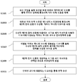
본 발명의 다른 일 실시예에 따른 복수의 송신 코일이 구비된 무선 전력 전송 시스템에서 멀티 코일 무선 전력 전송 방법은 n개의 그룹에 상기 그룹 별 복수의 송신 코일을 할당하는 단계와 상기 그룹 별 제1 감지 신호를 주기적으로 송출하는 단계와 송출된 상기 제1 감지 신호에 대응하여 제1 시그널 세기 지시자가 수신된 그룹을 식별하는 단계와 식별된 상기 그룹 내 할당된 복수의 송신 코일을 이용하여 제2 감지 신호를 송출하는 단계와 송출된 상기 제2 감지 신호에 대응하여 수신된 제2 시그널 세기 지시자에 기반하여 상기 식별된 그룹 별 전력 전송에 사용할 적어도 하나의 송신 코일을 선택하는 단계를 포함할 수 있다.A method for transmitting multi-coil radio power in a radio power transmission system having a plurality of transmission coils according to another embodiment of the present invention includes the steps of: allocating a plurality of transmission coils per group to n groups; The method of
여기서, 상기 제1 감지 신호는 상기 그룹 별 할당된 복수의 송신 코일 중 특정 하나의 송신 코일을 통해 소정 주기로 송출될 수 있다.Here, the first sensing signal may be transmitted at a predetermined cycle through a specific one of the plurality of transmission coils allocated to each group.
또한, 상기 특정 하나의 송신 코일은 상기 그룹 별 상기 무선 전력 전송 시스템에 배치된 복수의 송신 코일 중 중앙에 배치된 송신 코일일 수 있다. In addition, the specific one transmission coil may be a center transmission coil among a plurality of transmission coils disposed in the group-by-group wireless power transmission system.
또한, 상기 제1 감지 신호는 상기 n개의 그룹에 대응되는 제1 내지 제n 서브 무선 전력 송신기에서 소정 주기로 동시에 송출될 수 있다.Also, the first sensing signal may be simultaneously transmitted from the first through nth sub wireless power transmitters corresponding to the n groups at predetermined intervals.
이때, 상기 제1 내지 제n 서브 무선 전력 송신기 별 할당된 서로 다른 주파수를 이용하여 상기 제1 감지 신호가 동시에 송출될 수 있다.At this time, the first sensing signals may be simultaneously transmitted using different frequencies allocated to the first to nth sub wireless power transmitters.
또한, 상기 제1 내지 제n 서브 무선 전력 송신기 별 할당된 서로 다른 코드를 이용하여 상기 제1 감지 신호가 동시에 송출될 수도 있다.Also, the first sensing signals may be simultaneously transmitted using different codes allocated to the first to nth sub wireless power transmitters.
여기서, 상기 코드는 직교 다중화 코드를 포함할 수 있다. Here, the code may include an orthogonal multiplexing code.
또한, 상기 제1 감지 신호는 상기 그룹 별 할당된 복수의 송신 코일에 상응하여 미리 정의된 순서에 기반하여 전송될 수 있다.The first sensing signal may be transmitted based on a predefined sequence corresponding to a plurality of transmission coils allocated to each group.
또한, 상기 제1차 감지 신호 및 상기 제2차 감지 신호는 WPC 표준 또는 PMA 표준에 정의된 디지털 핑 신호일 수 있다.In addition, the first differential signal and the second differential signal may be digital ping signals defined in the WPC standard or the PMA standard.
또한, 상기 제2 감지 신호는 상기 식별된 그룹에 할당된 복수의 송신 코일에 상응하여 미리 정의된 순서에 기반하여 송출될 수 있다.In addition, the second sensing signal may be transmitted based on a predefined sequence corresponding to a plurality of transmission coils assigned to the identified group.
또한, 상기 식별된 그룹이 복수개인 경우, 상기 식별된 그룹 사이에서의 상기 제2 감지 신호의 송출 순서는 상기 제1 시그널 세기 지시자에 기반하여 결정될 수 있다. In addition, when there are a plurality of the identified groups, the transmission order of the second sensing signal among the identified groups may be determined based on the first signal strength indicator.
또한, 상기 제1 감지 신호와 상기 제2 감지 신호의 출력 전압 세기, 전송 주기 및 전송 시간 중 적어도 하나가 서로 상이할 수 있다.Also, at least one of the output voltage intensity, the transmission period, and the transmission time of the first sensing signal and the second sensing signal may be different from each other.
본 발명의 또 다른 일 실시예는 상기 멀티 코일 무선 충전 방법들 중 어느 하나의 방법을 실행시키기 위한 프로그램을 기록한 컴퓨터로 읽을 수 있는 기록매체가 제공될 수 있다.According to another embodiment of the present invention, there is provided a computer-readable recording medium having recorded thereon a program for executing the method of any one of the above-described multi-coil wireless charging methods.
본 발명의 또 다른 일 실시예에 따른 복수의 송신 코일이 구비된 차량용 무선 전력 전송 시스템은 충전 영역 내 진입한 차량의 현재 위치를 감지하기 위한 센서와 각각 복수의 송신 코일이 구비되며, 제1 감지 신호를 송출하는 제1 내지 제n 서브 무선 전력 송신기와 상기 제1 감지 신호에 대응하는 제1 시그널 세기 지시자의 수신 여부에 기반하여 제2 감지 신호를 송출할 서브 무선 전력 송신기를 식별하는 주제어부를 포함하되, 상기 센서에 의해 감지된 차량의 현재 위치에 대응되는 상기 적어도 하나의 서브 무선 전력 송신기를 이용하여 상기 제1 감지 신호가 송출될 수 있다.The present invention provides a vehicle wireless power transmission system having a plurality of transmission coils, comprising: a sensor for sensing a current position of a vehicle entering a charging area; and a plurality of transmission coils, And a main controller for identifying a sub wireless power transmitter to which the second detection signal is to be transmitted based on whether or not the first to nth sub wireless power transmitters and the first signal strength indicator corresponding to the first sensing signal are transmitted The first sensing signal may be transmitted using the at least one sub wireless power transmitter corresponding to the current position of the vehicle sensed by the sensor.
또한, 상기 센서는 상기 차량 바퀴의 압력을 감지하고, 소정 기준치 이상의 압력이 감지되면, 해당 위치 정보를 상기 주제어부에 전송할 수 있다.In addition, the sensor senses the pressure of the vehicle wheel, and when the pressure higher than a predetermined reference value is detected, the sensor can transmit the position information to the main control unit.
여기서, 상기 주제어부는 상기 위치 정보가 소정 시간 동안 변경되지 않는 경우, 상기 차량이 완전히 정차한 것으로 판단하되, 상기 차량이 완전히 정차한 경우, 상기 서브 무선 전력 송신기가 상기 제1 감지 신호를 송출하도록 제어할 수 있다.Here, if the position information is not changed for a predetermined time, the main control unit determines that the vehicle is completely stopped, and when the vehicle is completely stopped, the subordinate wireless power transmitter controls to transmit the first sensing signal can do.
또한, 상기 센서는 동축 케이블 형태의 피에조 센서를 포함할 수 있다.The sensor may also include a piezo sensor in the form of a coaxial cable.
상기 본 발명의 양태들은 본 발명의 바람직한 실시예들 중 일부에 불과하며, 본원 발명의 기술적 특징들이 반영된 다양한 실시예들이 당해 기술분야의 통상적인 지식을 가진 자에 의해 이하 상술할 본 발명의 상세한 설명을 기반으로 도출되고 이해될 수 있다.While the present invention has been particularly shown and described with reference to exemplary embodiments thereof, it is to be understood that the invention is not limited to the disclosed exemplary embodiments, but, on the contrary, And can be understood and understood.
본 발명에 따른 방법 및 장치에 대한 효과에 대해 설명하면 다음과 같다.Effects of the method and apparatus according to the present invention will be described as follows.
본 발명은 멀티 코일 무선 충전 방법 및 그를 위한 장치 및 시스템을 제공하는 장점이 있다.The present invention has the advantage of providing a multi-coil wireless charging method and apparatus and system therefor.
또한, 본 발명은 무선 전력 수신기에 대한 인식률을 높이고, 인식에 소요되는 시간을 최소화하는 것이 가능한 멀티 코일 무선 충전 방법 및 그를 위한 장치 및 시스템을 제공하는 장점이 있다.In addition, the present invention has an advantage of providing a multi-coil wireless charging method capable of increasing the recognition rate for a wireless power receiver and minimizing the time required for recognition, and an apparatus and system therefor.
또한, 본 발명은 복수의 송신 코일을 소정 개수의 그룹으로 구분하고, 그룹 별 무선 전력 수신기에 대한 감지 절차를 수행함으로써, 무선 전력 수신기의 인식에 소요되는 시간 및 대기 전력 소모를 최소화시키는 것이 가능한 멀티 코일 무선 충전 방법 및 그를 위한 장치 및 시스템을 제공하는 장점이 있다.In addition, the present invention can divide a plurality of transmission coils into a predetermined number of groups, perform a detection procedure for each group of wireless power receivers, and thereby minimize the time and standby power consumption required for recognition of the wireless power receiver. There is an advantage of providing a coil wireless charging method and apparatus and system therefor.
또한, 본 발명은 적어도 하나의 송신 코일이 구비된 복수의 무선 전력 송신기가 탑재된 무선 전력 전송 시스템에서 무선 전력 송신기 별 무선 전력 수신기의 감지 결과에 기반하여 무선 전력 송신기 별 제어될 송신 코일을 동적으로 재할당함으로써, 무선 전력 전송 시스템상에서의 송신 코일의 이용을 최적화시키는 것이 가능한 멀티 코일 무선 충전 방법 및 그를 위한 장치 및 시스템을 제공하는 장점이 있다.The present invention also relates to a method and apparatus for dynamically controlling a transmit coil to be controlled by a wireless power transmitter based on a detection result of a wireless power receiver for each wireless power transmitter in a wireless power transmission system equipped with a plurality of wireless power transmitters equipped with at least one transmission coil There is an advantage in providing a multi-coil wireless charging method and apparatus and system therefor that are capable of optimizing the use of the transmission coil on a wireless power transmission system by reassignment.
본 발명에서 얻을 수 있는 효과는 이상에서 언급한 효과들로 제한되지 않으며, 언급하지 않은 또 다른 효과들은 아래의 기재로부터 본 발명이 속하는 기술분야에서 통상의 지식을 가진 자에게 명확하게 이해될 수 있을 것이다.The effects obtained by the present invention are not limited to the above-mentioned effects, and other effects not mentioned can be clearly understood by those skilled in the art from the following description will be.
이하에 첨부되는 도면들은 본 발명에 관한 이해를 돕기 위한 것으로, 상세한 설명과 함께 본 발명에 대한 실시예들을 제공한다. 다만, 본 발명의 기술적 특징이 특정 도면에 한정되는 것은 아니며, 각 도면에서 개시하는 특징들은 서로 조합되어 새로운 실시예로 구성될 수 있다.
도 1은 종래 기술에 따른 무선 전력 송신기에서의 감지 신호 전송 절차를 설명하기 위한 도면이다.
도 2는 WPC 표준에 정의된 무선 전력 전송 절차를 설명하기 위한 상태 천이도이다.
도 3은 PMA 표준에 정의된 무선 전력 전송 절차를 설명하기 위한 상태 천이도이다.
도 4 내지 5는 본 발명의 일 실시예에 따른 송신 코일 별 할당된 서로 다른 주파수를 이용하여 감지 신호를 동시에 송출하여 무선 전력 수신기를 인식하는 방법을 설명하기 위한 도면이다.
도 6은 본 발명의 일 실시예에 따른 송신 코일 별 할당된 서로 다른 주파수를 이용하여 감지 신호를 송출하는 것이 가능한 멀티 코일 무선 전력 송신기의 구조를 설명하기 위한 블록도이다.
도 7은 상기 도 6에 따른 무선 전력 송신기와 연동되는 무선 전력 수신기의 구조를 설명하기 위한 블록도이다.
도 8은 본 발명의 일 실시예에 따른 송신 코일 별 서로 다른 주파수를 이용하여 감지 신호를 송출하는 것이 가능한 멀티 코일 무선 전력 송신기에서의 멀티 코일 무선 충전 방법을 설명하기 위한 순서도이다.
도 9는 본 발명의 일 실시예에 따른 송신 코일 별 서로 다른 주파수를 이용하여 송출된 감지 신호를 수신하는 것이 가능한 무선 전력 수신기에서의 멀티 코일 무선 충전 방법을 설명하기 위한 순서도이다.
도 10 내지 11은 본 발명의 일 실시예에 따른 송신 코일 별 서로 다른 코드로 암호화된 감지 신호를 동시에 송출하여 무선 전력 수신기를 인식하는 방법을 설명하기 위한 도면이다.
도 12는 본 발명의 일 실시예에 따른 송신 코일 별 서로 다른 코드로 암호화된 감지 신호를 송출하는 것이 가능한 무선 전력 송신기의 구조를 설명하기 위한 블록도이다.
도 13은 상기 도 12에 따른 무선 전력 송신기와 연동되는 무선 전력 수신기의 구조를 설명하기 위한 블록도이다.
도 14는 본 발명의 일 실시예에 따른 송신 코일 별 서로 다른 코드를 이용하여 암호화된 감지 신호를 송출하는 것이 가능한 멀티 코일 무선 전력 송신기에서의 멀티 코일 무선 충전 방법을 설명하기 위한 순서도이다.
도 15는 본 발명의 일 실시예에 따른 송신 코일 별 서로 다른 코드를 이용하여 송출된 감지 신호를 수신하는 것이 가능한 무선 전력 수신기에서의 멀티 코일 무선 충전 방법을 설명하기 위한 순서도이다.
도 16은 본 발명의 일 실시예에 따른 복수의 송신 코일이 장착된 무선 전력 전송 시스템을 설명하기 위한 도면이다.
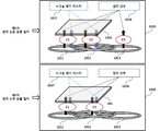
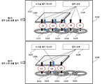
도 17은 본 발명의 일 실시예에 따른 무선 전력 전송 시스템에서의 제1 감지 신호 전송 절차를 설명하기 위한 도면이다.
도 18은 본 발명의 일 실시예에 따른 무선 전력 전송 시스템에서의 제2 감지 신호 전송 절차를 설명하기 위한 도면이다.
도 19는 본 발명의 다른 일 실시예에 따른 무선 전력 전송 시스템에서의 그룹 별 송신 코일 배치 방법을 설명하기 위한 도면이다.
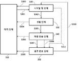
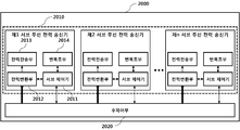
도 20은 본 발명의 일 실시예에 따른 무선 전력 전송 시스템의 구성을 설명하기 위한 블록도이다.
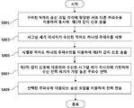
도 21은 본 발명의 일 실시예에 따른 복수의 송신 코일이 구비된 무선 전력 전송 시스템에서의 멀티 코일 무선 충전 방법을 설명하기 위한 순서도이다.BRIEF DESCRIPTION OF THE DRAWINGS The accompanying drawings, which are included to provide a further understanding of the invention and are incorporated in and constitute a part of this specification, illustrate embodiments of the invention and, together with the description, serve to explain the principles of the invention. It is to be understood, however, that the technical features of the present invention are not limited to the specific drawings, and the features disclosed in the drawings may be combined with each other to constitute a new embodiment.
1 is a diagram for explaining a sensing signal transmission procedure in a wireless power transmitter according to the related art.
2 is a state transition diagram for explaining a wireless power transmission procedure defined in the WPC standard.
3 is a state transition diagram for explaining a wireless power transmission procedure defined in the PMA standard;
FIGS. 4 and 5 are diagrams for explaining a method of simultaneously sensing signals transmitted at different frequencies allocated to each transmission coil according to an embodiment of the present invention to recognize a wireless power receiver.
FIG. 6 is a block diagram illustrating a structure of a multi-coil wireless power transmitter capable of transmitting a sensing signal using different frequencies assigned to each transmission coil according to an embodiment of the present invention. Referring to FIG.
FIG. 7 is a block diagram illustrating a structure of a wireless power receiver interworking with the wireless power transmitter of FIG.
FIG. 8 is a flowchart illustrating a multi-coil wireless charging method in a multi-coil wireless power transmitter capable of transmitting a sensing signal using different frequencies according to an embodiment of the present invention.
9 is a flowchart for explaining a multi-coil wireless charging method in a wireless power receiver capable of receiving a sensing signal transmitted using different frequencies for each transmission coil according to an embodiment of the present invention.
10 to 11 are diagrams for explaining a method of simultaneously detecting a wireless power receiver by simultaneously transmitting detection signals encrypted with different codes according to an embodiment of the present invention.
FIG. 12 is a block diagram illustrating a structure of a wireless power transmitter capable of transmitting a sensing signal encrypted with a different code for each transmission coil according to an embodiment of the present invention.
13 is a block diagram for explaining a structure of a wireless power receiver interworking with the wireless power transmitter according to the FIG.
FIG. 14 is a flowchart illustrating a multi-coil wireless charging method in a multi-coil wireless power transmitter capable of transmitting an encrypted sensing signal using different codes according to an embodiment of the present invention.
15 is a flowchart for explaining a multi-coil wireless charging method in a wireless power receiver capable of receiving a sensing signal transmitted using different codes according to an embodiment of the present invention.
16 is a view for explaining a wireless power transmission system equipped with a plurality of transmission coils according to an embodiment of the present invention.
17 is a diagram for explaining a first sensing signal transmission procedure in a wireless power transmission system according to an embodiment of the present invention.
18 is a diagram for explaining a second sensing signal transmission procedure in a wireless power transmission system according to an embodiment of the present invention.
FIG. 19 is a diagram for explaining a group-by-group transmission coil arrangement method in a wireless power transmission system according to another embodiment of the present invention.
20 is a block diagram illustrating a configuration of a wireless power transmission system according to an embodiment of the present invention.
21 is a flowchart for explaining a multi-coil wireless charging method in a wireless power transmission system having a plurality of transmission coils according to an embodiment of the present invention.
이하, 본 발명의 실시예들이 적용되는 장치 및 다양한 방법들에 대하여 도면을 참조하여 보다 상세하게 설명한다. 이하의 설명에서 사용되는 구성요소에 대한 접미사 "모듈" 및 "부"는 명세서 작성의 용이함만이 고려되어 부여되거나 혼용되는 것으로서, 그 자체로 서로 구별되는 의미 또는 역할을 갖는 것은 아니다.DETAILED DESCRIPTION OF THE PREFERRED EMBODIMENTS Hereinafter, an apparatus and various methods to which embodiments of the present invention are applied will be described in detail with reference to the drawings. The suffix "module" and " part "for the components used in the following description are given or mixed in consideration of ease of specification, and do not have their own meaning or role.
실시예의 설명에 있어서, 각 구성 요소의 " 상(위) 또는 하(아래)"에 형성되는 것으로 기재되는 경우에 있어, 상(위) 또는 하(아래)는 두개의 구성 요소들이 서로 직접 접촉되거나 하나 이상의 또 다른 구성 요소가 두 개의 구성 요소들 사이에 배치되어 형성되는 것을 모두 포함한다. 또한 “상(위) 또는 하(아래)"로 표현되는 경우 하나의 구성 요소를 기준으로 위쪽 방향뿐만 아니라 아래쪽 방향의 의미도 포함할 수 있다.In the description of the embodiment, in the case where it is described as being formed "above" or "below" each element, the upper or lower (lower) And that at least one further component is formed and arranged between the two components. Also, in the case of "upper (upper) or lower (lower)", it may include not only the upward direction but also the downward direction based on one component.
실시예의 설명에 있어서, 무선 전력 시스템상에서 무선 전력을 송신하는 장치는 설명의 편의를 위해 무선 파워 송신기, 무선 파워 송신 장치, 무선 전력 송신 장치, 무선 전력 송신기, 송신단, 송신기, 송신 장치, 송신측, 무선 파워 전송 장치, 무선 파워 전송기 등을 혼용하여 사용하기로 한다. 또한, 무선 전력 송신 장치로부터 무선 전력을 수신하는 장치에 대한 표현으로 설명의 편의를 위해 무선 전력 수신 장치, 무선 전력 수신기, 무선 파워 수신 장치, 무선 파워 수신기, 수신 단말기, 수신측, 수신 장치, 수신기 등이 혼용되어 사용될 수 있다.In the description of the embodiments, an apparatus for transmitting wireless power on a wireless power system includes a wireless power transmitter, a wireless power transmitter, a wireless power transmitter, a wireless power transmitter, a transmitter, a transmitter, a transmitter, A wireless power transmission device, a wireless power transmitter, and the like are used in combination. Also, for the sake of convenience of explanation, it is to be understood that a wireless power receiving apparatus, a wireless power receiving apparatus, a wireless power receiving apparatus, a wireless power receiving apparatus, a receiving terminal, a receiving side, a receiving apparatus, Etc. may be used in combination.
본 발명에 따른 송신기는 패드 형태, 거치대 형태, AP(Access Point) 형태, 소형 기지국 형태, 스텐드 형태, 천장 매립 형태, 벽걸이 형태 등으로 구성될 수 있으며, 하나의 송신기는 복수의 무선 전력 수신 장치에 파워를 전송할 수도 있다. 이를 위해, 송신기는 적어도 하나의 무선 파워 전송 수단을 구비할 수도 있다. 여기서, 무선 파워 전송 수단은 전력 송신단 코일에서 자기장을 발생시켜 그 자기장의 영향으로 수신단 코일에서 전기가 유도되는 전자기유도 원리를 이용하여 충전하는 전자기 유도 방식에 기반한 다양한 무전 전력 전송 표준이 사용될 수 있다. 여기서, 무선파워 전송 수단은 무선 충전 기술 표준 기구인 WPC(Wireless Power Consortium) 및 PMA(Power Matters Alliance)에서 정의된 전자기 유도 방식의 무선 충전 기술을 포함할 수 있다.The transmitter according to the present invention may be configured as a pad type, a cradle type, an access point (AP) type, a small base type, a stand type, a ceiling embedded type, a wall type, Power can also be transmitted. To this end, the transmitter may comprise at least one radio power transmission means. Here, the radio power transmitting means may be various non-electric power transmission standards based on an electromagnetic induction method in which a magnetic field is generated in a power transmitting terminal coil and charged using an electromagnetic induction principle in which electricity is induced in a receiving terminal coil under the influence of the magnetic field. Here, the wireless power transmission means may include an electromagnetic induction wireless charging technique defined by Wireless Power Consortium (WPC) and Power Matters Alliance (PMA), which are standard wireless charging technologies.
또한, 본 발명의 일 실시예에 따른 수신기는 적어도 하나의 무선 전력 수신 수단이 구비될 수 있으며, 2개 이상의 송신기로부터 동시에 무선 파워를 수신할 수도 있다. 여기서, 무선 전력 수신 수단은 무선 충전 기술 표준 기구인 WPC(Wireless Power Consortium) 및 PMA(Power Matters Alliance)에서 정의된 전자기 유도 방식의 무선 충전 기술을 포함할 수 있다.Also, a receiver according to an embodiment of the present invention may include at least one wireless power receiving means, and may receive wireless power from two or more transmitters at the same time. Here, the wireless power receiving means may include an electromagnetic induction wireless charging technique defined by Wireless Power Consortium (WPC) and Power Matters Alliance (PMA), which are standard wireless charging technologies.
본 발명에 따른 수신기는 휴대폰(mobile phone), 스마트폰(smart phone), 노트북 컴퓨터(laptop computer), 디지털방송용 단말기, PDA(Personal Digital Assistants), PMP(Portable Multimedia Player), 네비게이션, MP3 player, 전동 칫솔, 전자 태그, 조명 장치, 리모콘, 낚시찌, 스마트 워치와 같은 웨어러블 디바이스 등의 소형 전자 기기 등에 사용될 수 있으나, 이에 국한되지는 아니하며 본 발명에 따른 무선 전력 수신 수단이 장착되어 배터리 충전이 가능한 기기라면 족하다. The receiver according to the present invention may be used in a mobile phone, a smart phone, a laptop computer, a digital broadcasting terminal, a PDA (Personal Digital Assistants), a PMP (Portable Multimedia Player), a navigation device, A portable electronic device such as a toothbrush, an electronic tag, a lighting device, a remote control, a fishing rod, a smart watch, etc. However, the present invention is not limited thereto. It suffices.
도 1은 종래 기술에 따른 무선 전력 송신기에서의 감지 신호 전송 절차를 설명하기 위한 도면이다. 1 is a diagram for explaining a sensing signal transmission procedure in a wireless power transmitter according to the related art.
도 1을 참조하면, 무선 전력 송신기는 3개의 송신 코일(111, 112, 113)이 장착될 수 있다. 각각의 송신 코일은 일부 영역이 다른 송신 코일과 서로 중첩될 수 있으며, 무선 전력 송신기는 각각의 송신 코일을 통해 무선 전력 수신기의 존재를 감지하기 위한 소정 감지 신호(117, 127)-예를 들면, 디지털 핑 신호-를 미리 정의된 순서로 순차적으로 송출한다.Referring to FIG. 1, the wireless power transmitter may be equipped with three
상기 도 1에 도시된 바와 같이, 무선 전력 송신기는 도면 번호 110에 도시된 1차 감지 신호 송출 절차를 통해 감지 신호(117)를 순차적으로 송출하고, 무선 전력 수신기(115)로부터 시그널 세기 지시자 또는 시그널 강도 지시자(Signal Strength Indicator, 116)가 수신된 송신 코일(111, 112)을 식별할 수 있다. 연이어, 무선 전력 송신기는 도면 번호 120에 도시된 2차 감지 신호 송출 절차를 통해 감지 신호(127)를 순차적으로 송출하고, 시그널 세기 지시자(126)가 수신된 송신 코일(111, 112) 중 전력 전송 효율(또는 충전 효율)-즉, 송신 코일과 수신 코일 사이의 정렬 상태-이 좋은 송신 코일을 식별하고, 식별된 송신 코일을 통해 전력이 송출되도록-즉, 무선 충전이 이루어지도록- 제어할 수 있다. As shown in FIG. 1, the wireless power transmitter sequentially transmits the
상기의 도 1에서 보여지는 바와 같이, 무선 전력 송신기가 2회의 감지 신호 송출 절차를 수행하는 이유는 어느 송신 코일에 무선 전력 수신기의 수신 코일이 잘 정렬되어 있는지를 보다 정확하게 식별하기 위함이다.As shown in FIG. 1, the reason why the wireless power transmitter performs the two detection signal transmission procedures is to more accurately identify to which transmission coil the reception coil of the wireless power receiver is well aligned.
만약, 상기한 도 1의 도면 번호 110 및 120에 도시된 바와 같이, 제1 송신 코일(111), 제2 송신 코일(112)에 시그널 세기 지시자(116, 126)가 수신된 경우, 무선 전력 송신기는 제1 송신 코일(111)과 제2 송신 코일(112) 각각에 수신된 시그널 세기 지시자(126)에 기반하여 가장 정렬이 잘된 송신 코일을 선택하고, 선택된 송신 코일을 이용하여 무선 충전을 수행한다. If the
도 2는 WPC 표준에 정의된 무선 전력 전송 절차를 설명하기 위한 상태 천이도이다.2 is a state transition diagram for explaining a wireless power transmission procedure defined in the WPC standard.
도 2를 참조하면, WPC 표준에 따른 송신기로부터 수신기로의 파워 전송은 크게 선택 단계(Selection Phase, 210), 핑 단계(Ping Phase, 220), 식별 및 구성 단계(Identification and Configuration Phase, 230), 파워 전송 단계(Power Transfer Phase, 240) 단계로 구분될 수 있다.Referring to FIG. 2, power transmission from a transmitter to a receiver according to the WPC standard is largely divided into a
선택 단계(210)는 파워 전송을 시작하거나 파워 전송을 유지하는 동안 특정 오류 또는 특정 이벤트가 감지되면, 천이되는 단계일 수 있다. 여기서, 특정 오류 및 특정 이벤트는 이하의 설명을 통해 명확해질 것이다. 또한, 선택 단계(210)에서 송신기는 인터페이스 표면에 물체가 존재하는지를 모니터링할 수 있다. 만약, 송신기가 인터페이스 표면에 물체가 놓여진 것이 감지되면, 핑 단계(220)로 천이할 수 있다(S201). 선택 단계(210)에서 송신기는 매우 짧은 펄스의 아날로그 핑(Analog Ping) 신호를 전송하며, 송신 코일의 전류 변화에 기반하여 인터페이스 표면의 활성 영역(Active Area)에 물체가 존재하는지를 감지할 수 있다. The
핑 단계(220)에서 송신기는 물체가 감지되면, 수신기를 활성화시키고, 수신기가 WPC 표준이 호환되는 수신기인지를 식별하기 위한 디지털 핑(Digital Ping)을 전송한다. 핑 단계(220)에서 송신기는 디지털 핑에 대한 응답 시그널-예를 들면, 시그널 세기 지시자-을 수신기로부터 수신하지 못하면, 다시 선택 단계(210)로 천이할 수 있다(S202). 또한, 핑 단계(220)에서 송신기는 수신기로부터 파워 전송이 완료되었음을 지시하는 신호-즉, 충전 완료 신호-를 수신하면, 선택 단계(210)로 천이할 수도 있다(S203).In
핑 단계(220)가 완료되면, 송신기는 수신기 식별 및 수신기 구성 및 상태 정보를 수집하기 위한 식별 및 구성 단계(230)로 천이할 수 있다(S204).Once the
식별 및 구성 단계(230)에서 송신기는 원하지 않은 패킷이 수신되거나(unexpected packet), 미리 정의된 시간 동안 원하는 패킷이 수신되지 않거나(time out), 패킷 전송 오류가 있거나(transmission error), 파워 전송 계약이 설정되지 않으면(no power transfer contract) 선택 단계(210)로 천이할 수 있다(S205).In the identifying and configuring
수신기에 대한 식별 및 구성이 완료되면, 송신기는 무선 전력을 전송하는 파워 전송 단계(240)로 천이할 수 있다(S206).Once the identification and configuration for the receiver is complete, the transmitter may transition to
파워 전송 단계(240)에서, 송신기는 원하지 않은 패킷이 수신되거나(unexpected packet), 미리 정의된 시간 동안 원하는 패킷이 수신되지 않거나(time out), 기 설정된 파워 전송 계약에 대한 위반이 발생되거나(power transfer contract violation), 충전이 완료된 경우, 선택 단계(210)로 천이할 수 있다(S207).In a
또한, 파워 전송 단계(240)에서, 송신기는 송신기 상태 변화 등에 따라 파워 전송 계약을 재구성할 필요가 있는 경우, 식별 및 구성 단계(230)로 천이할 수 있다(S208).Also, in
상기한 파워 전송 계약은 송신기와 수신기의 상태 및 특성 정보에 기반하여 설정될 수 있다. 일 예로, 송신기 상태 정보는 최대 전송 가능한 파워량에 대한 정보, 최대 수용 가능한 수신기 개수에 대한 정보 등을 포함할 수 있으며, 수신기 상태 정보는 요구 전력에 대한 정보 등을 포함할 수 있다.The power transmission contract may be set based on the status and characteristic information of the transmitter and the receiver. For example, the transmitter status information may include information on the maximum amount of transmittable power, information on the maximum number of receivable receivers, and the receiver status information may include information on the requested power and the like.
도 3은 PMA 표준에 정의된 무선 전력 전송 절차를 설명하기 위한 상태 천이도이다.3 is a state transition diagram for explaining a wireless power transmission procedure defined in the PMA standard;
도 3을 참조하면, PMA 표준에 따른 송신기로부터 수신기로의 파워 전송은 크게 대기 단계(Standby Phase, 310), 디지털 핑 단계(Digital Ping Phase, 320), 식별 단계(Identification Phase, 330), 파워 전송 단계(Power Transfer Phase, 340) 단계 및 충전 완료 단계(End of Charge Phase, 350)로 구분될 수 있다.Referring to FIG. 3, the power transmission from the transmitter to the receiver according to the PMA standard is largely divided into a
대기 단계(310)는 파워 전송을 위한 수신기 식별 절차를 수행하거나 파워 전송을 유지하는 동안 특정 오류 또는 특정 이벤트가 감지되면, 천이되는 단계일 수 있다. 여기서, 특정 오류 및 특정 이벤트는 이하의 설명을 통해 명확해질 것이다. 또한, 대기 단계(310)에서 송신기는 충전 표면(Charging Surface)에 물체가 존재하는지를 모니터링할 수 있다. 만약, 송신기가 충전 표면에 물체가 놓여진 것이 감지되거나 RXID 재시도가 진행중인 경우, 디지털 핑 단계(320)로 천이할 수 있다(S301). 여기서, RXID는 PMA 호환 수신기에 할당되는 고유 식별자이다. 대기 단계(310)에서 송신기는 매우 짧은 펄스의 아날로그 핑(Analog Ping)을 전송하며, 송신 코일의 전류 변화에 기반하여 인터페이스 표면-예를 들면, 충전 베드-의 활성 영역(Active Area)에 물체가 존재하는지를 감지할 수 있다.The waiting
디지털 핑 단계(320)로 천이된 송신기는 감지된 물체가 PMA 호환 수신기인지를 식별하기 위한 디지털 핑 신호를 송출한다. 송신기가 전송한 디지털 핑 신호에 의해 수신단에 충분한 전력이 공급되는 경우, 수신기는 수신된 디지털 핑 신호를 PMA 통신 프로토콜에 따라 변조하여 소정 응답 시그널을 송신기에 전송할 수 있다. 여기서, 응답 시그널은 수신기에 수신된 전력의 세기를 지시하는 신호 세기 지시자가 포함될 수 있다. 디지털 핑 단계(320)에서 수신기는 유효한 응답 시그널이 수신되면, 식별 단계(330)로 천이할 수 있다(S302).The transmitter transited to the
만약, 디지털 핑 단계(320)에서, 응답 시그널이 수신되지 않거나, PMA 호환 수신기가 아닌 것으로 확인되면-즉, FOD(Foreign Object Detection)인 경우-, 송신기는 대기 단계(310)로 천이할 수 있다(S303). 일 예로, FO(Foreign Object)는 동전, 키 등을 포함하는 금속성 물체일 수 있다.If the response signal is not received or it is determined that it is not a PMA compatible receiver, i.e., it is a Foreign Object Detection (FOD), at
식별 단계(330)에서, 송신기는 수신기 식별 절차가 실패하거나 수신기 식별 절차를 재수행하여야 하는 경우 및 미리 정의된 시간 동안 수신기 식별 절차를 완료하지 못한 경우에 대기 단계(310)로 천이할 수 있다(S304).In the identifying
송신기는 수신기 식별에 성공하면, 식별 단계(330)에서 파워 전송 단계(340)로 천이하여 충전을 개시할 수 있다(S305).If the transmitter succeeds in identifying the receiver, the transmitter may transition to
파워 전송 단계(340)에서, 송신기는 원하는 신호가 미리 정해진 시간 이내에 수신되지 않거나(Time Out), FO가 감지되거나, 송신 코일의 전압이 미리 정의된 기준치를 초과하는 경우, 대기 단계(310)으로 천이할 수 있다(S306).In the
또한, 파워 전송 단계(340)에서, 송신기는 내부 구비된 온도 센서에 의해 감지된 온도가 소정 기준치를 초과하는 경우, 충전 완료 단계(350)로 천이할 수 있다(S307).In addition, in the
충전 완료 단계(350)에서, 송신기는 수신기가 충전 표면에서 제거된 것이 확인되면, 대기 상태(310)으로 천이할 수 있다(S309).In the
또한, 송신기는 Over Temperature 상태에서, 일정 시간 경과 후 측정된 온도가 기준치 이하로 떨어진 경우, 충전 완료 단계(350)에서 디지털 핑 단계(320)로 천이할 수 있다(S310).Also, if the measured temperature drops below the reference value in the over temperature state, the transmitter may transition from the charging
디지털 핑 단계(320) 또는 파워 전송 단계(340)에서, 송신기는 수신기로부터 EOC(End Of Charge) 요청이 수신되면, 충전 완료 단계(350)로 천이할 수도 있다(S308 및 S311). In the
도 4 내지 5는 본 발명의 일 실시예에 따른 송신 코일 별 할당된 서로 다른 주파수를 이용하여 감지 신호를 동시에 송출하여 무선 전력 수신기를 인식하는 방법을 설명하기 위한 도면이다.FIGS. 4 and 5 are diagrams for explaining a method of simultaneously sensing signals transmitted at different frequencies allocated to each transmission coil according to an embodiment of the present invention to recognize a wireless power receiver.
도 4를 참조하면, 무선 전력 송신기는 3개의 송신 코일(411, 412, 413)이 장착될 수 있다. 각각의 송신 코일은 일부 영역이 다른 송신 코일과 서로 중첩될 수 있으며, 무선 전력 송신기는 각각의 송신 코일을 통해 아날로그 핑 신호를 전송하거나 소정 감지 센서를 이용하여 전도성 물체의 존재가 감지되면, 해당 물체가 무선 충전이 가능한 무선 전력 수신기인지를 식별하기 위한 소정 감지 신호(417, 427)-예를 들면, 디지털 핑 신호-를 송신 코일 별 할당된 특정 주파수를 이용하여 동시에 송출할 수 있다. 일 예로, 도 4를 참조하면, 제1 내지 제3 송신 코일(411, 412, 413) 각각에 할당된 주파수는 f1, f2, f3일 수 있으며, f1, f2 및 f3는 서로 상이한 값을 가질 수 있다. 특히, 본 실시예에 따른 무선 전력 송신기는 상기 도 4에 도시된 바와 같이, 1차 감지 신호 송출 절차(410)에서는 각각의 송신 코일에 할당된 서로 다른 주파수를 이용하여 동시에 감지 신호(418)를 송출할 수 있다. 연이어, 2차 감지 신호 송출 절차(420)에서는 1차 감지 신호 송출 절차(410)에서 시그널 세기 지시자가 수신된 송신 코일(411, 412)에 대해서만 감지 신호(428)가 송출되도록 제어할 수 있다. 이때, 무선 전력 송신기는 제2차 감지 신호 송출 절차(420)에서 수신된 시그널 세기 지시자의 값에 기반하여 전력 전송을 위해 사용할 송신 코일-즉, 주파수-을 선택할 수 있다. 만약, 제2차 감지 신호 송출 절차(420)에서 수신된 시그널 세기 지시자 중 f1 주파수-즉, 제1 송신 코일(411)-를 통해 수신된 시그널 세기 지시자의 값이 f2 주파수-즉, 제2 송신 코일(412)를 통해 수신된 시그널 세기 지시자의 값에 비해 큰 값인 경우, 무선 전력 송신기는 f1 주파수-즉, 제1 송신 코일(411)-를 무선 전력 전송에 사용하도록 결정할 수 있다. 여기서, 시그널 세기 지시자의 값이 클수록 수신단에서 수신되는 전력의 세기가 큰 것을 의미할 수 있다. 일 예로, 시그널 세기 지시자는 수신단의 정류기 출력 전력의 세기에 기반하여 결정될 수 있으나, 이에 한정되지는 않으며, 수신단의 DC/DC 컨버터 후단 또는 배터리 출력 전압 등에 기반하여 결정될 수도 있다.Referring to FIG. 4, the wireless power transmitter may be equipped with three transmit
상기 도 4의 실시에에 따른 감지 신호(418, 428)는 WPC 표준 및 PMA 표준에 정의된 디지털 핑 신호일 수 있다.The sense signals 418 and 428 according to the embodiment of FIG. 4 may be digital finger signals defined in the WPC standard and the PMA standard.
도 5를 참조하면, 본 발명의 다른 일 실시예에 따른 무선 전력 송신기는 5개의 송신 코일(511 내지 515)이 장착될 수 있으며, 제1차 감지 신호 송출 절차(510) 동안 무선 전력 송신기는 송신 코일 별 서로 다른 주파수(f1, f2, f3, f4, f5)를 이용하여 감지 신호(518)를 동시에 송출할 수 있다. 이때, 무선 전력 송신기는 제1 내지 제3 송신 코일(511, 512, 513)에 의해 송출된 감지 신호에 대응되는 시그널 세기 지시자(517)를 무선 전력 수신기(501)로부터 수신할 수 있다.5, a wireless power transmitter according to another exemplary embodiment of the present invention may be equipped with five
이 경우, 무선 전력 송신기는 제2차 감지 신호 송출 절차(520)에서 상기 제1차 감지 신호 송출 절차에서 시그널 세기 지시자(517)가 수신된 제1 내지 제3 송신 코일(511, 512, 513)을 통해서만, 감지 신호(528)를 송출하고, 나머지 제4 내지 제5 송신 코일(514, 515)에는 감지 신호가 송출되지 않도록 제어할 수 있다. In this case, the wireless power transmitter transmits the first to third transmission coils 511, 512, and 513 in which the
무선 전력 수신기(501)는 제2차 감지 신호 송출 절차(520) 동안 수신된 감지 신호 중 세기가 가장 높은 감지 신호에 대응되는 주파수를 선택할 수 있다. 이때, 선택된 주파수가 f2인 것으로 가정한다. 이 경우, 무선 전력 수신기(501)는 f2 주파수를 통해 수신된 감지 신호에 대응되는 시그널 세기 지시자만을 송출할 수 있다.The
이 후, 무선 전력 송신기는 제2차 감지 신호 송출 절차(520) 동안 시그널 세기 지사자(527)가 수신된 송신 코일(512)-즉, f2 주파수-을 이용하여 수신기 식별 절차 및 전력 전송 절차를 수행할 수 있다.The wireless power transmitter then uses the transmit coil 512 (i.e., the f2 frequency) during which the
도 6은 본 발명의 일 실시예에 따른 송신 코일 별 할당된 서로 다른 주파수를 이용하여 감지 신호를 송출하는 것이 가능한 멀티 코일 무선 전력 송신기의 구조를 설명하기 위한 블록도이다.FIG. 6 is a block diagram illustrating a structure of a multi-coil wireless power transmitter capable of transmitting a sensing signal using different frequencies assigned to each transmission coil according to an embodiment of the present invention. Referring to FIG.
도 6을 참조하면 무선 전력 송신기(600)는 크게, 전력 변환부(610), 전력 전송부(620), 변조부(630), 복조부(631), 제어부(640), 감지 신호 전송 타이머(660)를 포함하여 구성될 수 있다. 상기한 무선 전력 송신기(600)의 구성은 반드시 필수적인 구성은 아니어서, 그보다 많거나 적은 구성 요소를 포함하여 구성될 수도 있음을 주의해야 한다.6, the
도 6에 도시된 바와 같이, 전력 변환부(610)는 전원부(650)로부터 전원이 공급되면, 이를 소정 세기의 전력으로 변환하는 기능을 수행할 수 있다.As shown in FIG. 6, when power is supplied from the
이를 위해, 전력 변환부(610)는 DC/DC 변환부(611), 전력 센서(612) 및 증폭기(613)를 포함하여 구성될 수 있다.The
DC/DC 변환부(611)는 전원부(650)로부터 공급된 DC 전력을 제어부(640)의 제어 신호에 따라 특정 세기의 DC 전력으로 변환하는 기능을 수행할 수 있다.The DC /
전력 센서(612)는 DC 변환된 전력의 전압/전류 등을 측정하여 제어부(640)에 제공할 수 있다.The
제어부(640)는 전력 센서(612)에 의해 측정된 전압/전류 값에 기반하여 적응적으로 전원부(650)로부터의 전원 공급을 차단하거나, 증폭기(613)에 전력이 공급되는 것을 차단할 수 있다. 이를 위해, 전력 변환부(610)의 일측에는 전원부(650)로부터 공급되는 전원을 차단하거나, 증폭기(613)에 공급되는 전력을 차단하기 위한 소정 전력 차단 회로가 가 더 구비될 수도 있다.The
증폭기(613)는 DC/DC 변환된 전력의 세기를 제어부(640)의 제어 신호에 따라 조정할 수 있다. 일 예로, 제어부(640)는 복조부(631)를 통해 무선 전력 수신기에 의해 생성된 소정 전력 제어 신호에 수신할 수 있으며, 수신된 전력 제어 신호에 따라 증폭기(613)의 증폭률을 조정할 수 있다.The
전력 전송부(620)는 스위치(621), 반송파 생성기(622), 송신 코일(623)을 포함하여 구성될 수 있다. The
반송파 생성기(622)는 스위치(621)를 통해 전달 받은 증폭기(613)의 출력 DC 전력에 특정 주파수를 갖는 AC 성분이 삽입된 AC 전력을 생성하여 해당 송신 코일에 전송하는 기능을 수행할 수 있다. 이때, 각각의 송신 코일에 전달되는 AC 전력의 주파수는 서로 상이할 수 있다.The
도 6에 도시된 바와 같이, 전력 전송부(620)는 증폭기(613)의 출력 전력이 송신 코일에 전달되는 것을 제어하기 위한 스위치(621)와 제1 내지 제n 송신 코일(622)을 포함하여 구성될 수 있다.6, the
제어부(640)는 제1차 감지 신호 송출 절차 동안 제1 내지 제n 송신 코일(622)을 통해 동시에 감지 신호가 송출될 수 있도록 스위치(621)를 제어할 수 있다. 이때, 제어부(640)는 감지 신호가 전송될 시점을 감지 신호 전송 타이머(660)를 통해 식별할 수 있으며, 감신 신호 전송 시점이 도래하면, 스위치(621)를 제어하여 해당 송신 코일을 통해 감지 신호가 송출될 수 있도록 제어할 수 있다.The
또한, 제어부(640)는 제1차 감지 신호 송출 절차 동안 복조부(631)로부터 어느 송신 코일을 통해 시그널 세기 지시자가 수신되었는지를 식별하기 위한 소정 송신 코일 식별자 및 해당 송신 코일을 통해 수신된 시그널 세기 지시자를 수신할 수 있다. 연이어, 제2차 감지 신호 송출 절차에서 제어부(640)는 제1차 감지 신호 송출 절차 동안 시그널 세기 지시자가 수신된 송신 코일(들)을 통해서만 감지 신호가 송출될 수 있도록 스위치(621)를 제어할 수 있다. 다른 일 예로, 제어부(640)는 제1차 감지 신호 송출 절차 동안 시그널 세기 지시자가 수신된 송신 코일이 복수개인 경우, 가장 큰 값을 갖는 시그널 세기 지시자가 수신된 송신 코일을 제2차 감지 신호 송출 절차에서 감지 신호를 송출할 송신 코일로 결정하고, 결정 결과에 따라 스위치(621)를 제어할 수 있다. In addition, the
변조부(630)는 제어부(640)에 의해 생성된 제어 신호를 변조하여 스위치(621)에 전달할 수 있다. 여기서, 제어 신호를 변조하기 위한 변조 방식은 FSK(Frequency Shift Keying) 변조 방식, 맨체스터 코딩(Manchester Coding) 변조 방식, PSK(Phase Shift Keying) 변조 방식 및 펄스 폭 변조 방식 등을 포함할 수 있다.The
복조부(631)는 송신 코일을 통해 수신되는 신호가 감지되면, 감지된 신호를 복조하여 제어부(640)에 전송할 수 있다. 여기서, 복조된 신호에는 시그널 제어 지시자, 무선 전력 전송 중 전력 제어를 위한 오류 정정(EC:Error Correction) 지시자, 충전 완료(EOC: End Of Charge) 지시자, 과전압/과전류/과열 지시자 등이 포함될 수 있으나, 이에 한정되지는 않으며, 무선 전력 수신기의 상태를 식별하기 위한 각종 상태 정보가 포함될 수 있다.The
또한, 복조부(631)는 복조된 신호가 어느 송신 코일로부터 수신된 신호인지를 식별할 수 있으며, 식별된 송신 코일에 상응하는 소정 송신 코일 식별자를 제어부(640)에 제공할 수도 있다. The
또한, 복조부(631)는 송신 코일(623)을 통해 수신된 신호를 복조하여 제어부(640)에 전달할 수 있다. 일 예로, 복조된 신호는 시그널 세기 지시자를 포함할 수 있으나, 이에 한정되지는 않으며, 복조 신호는 무선 전력 수신기의 각종 상태 정보를 포함할 수 있다. The
일 예로, 무선 전력 송신기(600)는 무선 전력 전송에 사용되는 동일한 주파수를 이용하여 무선 전력 수신기와 통신을 수행하는 인밴드(In-Band) 통신을 통해 상기 시그널 세기 지시자를 획득할 수 있다.For example, the
또한, 무선 전력 송신기(600)는 송신 코일(623)을 이용하여 무선 전력을 송출할 수 있을 뿐만 아니라 송신 코일(623)을 통해 무선 전력 수신기와 각종 정보를 교환할 수 있다. 다른 일 예로, 무선 전력 송신기(600)는 각각의 송신 코일(623)에 대응되는 별도의 코일을 구비하고, 구비된 별도의 코일을 이용하여 무선 전력 수신기와 인밴드 통신을 수행할 수도 있음을 주의해야 한다.In addition, the
도 7은 상기 도 6에 따른 무선 전력 송신기와 연동되는 무선 전력 수신기의 구조를 설명하기 위한 블록도이다.7 is a block diagram illustrating a structure of a wireless power receiver interworking with the wireless power transmitter according to the FIG.
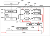
도 7을 참조하면, 무선 전력 수신기(700)는 수신 코일(710), 분배 스위치(720), 주파수 필터(730), 정류부(740), DC/DC 컨버터(750), 부하(760), 전력 센싱부(770), 주제어부(780), 변조부(790) 및 복조부(791)를 포함하여 구성될 수 있다.7, a wireless power receiver 700 includes a receive
수신 코일(710)을 통해 수신된 AC 전력은 분배 스위치(720)을 통해 주파수 필터(730)에 전달될 수 있다. 이때, 주파수 필터(730)는 복수의 서로 다른 반송 주파수를 필터링하여 정류부(740)에 전달할 수 있다. 정류부(740)는 필터링된 AC 전력을 DC 전력으로 변환하여 DC/DC 컨버터(750)에 전송할 수 있다. DC/DC 컨버터(750)는 정류기 출력 DC 전력의 세기를 부하(760)에 요구되는 세기로 변환하여 부하(760)에 전달할 수 있다.AC power received via receive
전력 센싱부(770)는 정류부(740)에 포함된 제1 내지 제n 정류기 각각의 출력 DC 전력의 세기를 측정하고, 이를 주제어부(780)에 제공할 수 있다.The
일 예로, 주제어부(780)는 측정된 정류기 출력 DC 전력의 세기가 소정 기준치 이상인 정류기를 식별하고 식별된 정류기에 대응되는 반송 주파수를 이용하여 시그널 세기 지시자가 송출될 수 있도록 변조부(790)를 제어할 수 있다. 즉, 주제어부(780)는 정류기 출력 DC 전력의 세기가 소정 기준치 이상인 경우, 감지 신호가 수신된 것으로 판단할 수 있으며, 감지 신호 수신 시, 해당 감지 신호 전송에 사용된 반송 주파수를 이용하여 감지 신호에 대응되는 시그널 세기 지시자가 전송될 수 있도록 변조부(790)를 제어할 수 있다.For example, the
다른 일 예로, 복조부(791)는 주파수 필터(730)의 출력 또는 정류부(740) 출력을 복조하여 감지 신호의 수신 여부를 식별할 수 있으며, 식별된 감지 신호가 어느 반송 주파수로 전송되었는지에 대한 정보를 주제어부(780)에 제공할 수 있다. 이때, 주제어부(780)는 식별된 감지 신호 전송에 사용된 반송 주파수와 동일한 주파수를 이용하여 시그널 세기 지시자가 변조부(790)를 통해 전송될 수 있도록 제어할 수 있다.In another example, the
도 8은 본 발명의 일 실시예에 따른 송신 코일 별 서로 다른 주파수를 이용하여 감지 신호를 송출하는 것이 가능한 멀티 코일 무선 전력 송신기에서의 멀티 코일 무선 충전 방법을 설명하기 위한 순서도이다.FIG. 8 is a flowchart illustrating a multi-coil wireless charging method in a multi-coil wireless power transmitter capable of transmitting a sensing signal using different frequencies according to an embodiment of the present invention.
도 8을 참조하면, 무선 전력 송신기는 구비된 N개의 송신 코일 각각에 할당된 서로 다른 주파수-즉, 반송 주파수-를 이용하여 동시에 제1차 감지 신호를 송출할 수 있다(S801).Referring to FIG. 8, the wireless power transmitter can simultaneously transmit the first detection signal using different frequencies assigned to the N transmit coils, that is, the carrier frequency (S801).
무선 전력 송신기는 시그널 세기 지시자가 수신된 적어도 하나의 주파수를 식별하고(S803), 식별된 적어도 하나의 주파수만을 이용하여 제2차 감지 신호를 송출할 수 있다(S805).The wireless power transmitter may identify the at least one frequency at which the signal strength indicator is received (S803) and transmit the secondary sensed signal using only the identified at least one frequency (S805).
무선 전력 송신기는 제2 감지 신호에 대응하여 수신된 시그널 세기 지시자에 기반하여 무선 전력 수신기에서 수신된 전력의 세기가 가장 높은 주파수를 선택할 수 있다(S807). 일 예로, 제2 감지 신호 전송에 따라 무선 전력 송신기에서 송신 코일을 통해 수신되는 시그널 세기 지시자의 개수는 복수일 수 있다. 이 경우, 무선 전력 송신기는 가장 큰 시그널 세기 지시자가 수신된 송신 코일을 해당 무선 전력 수신기로의 전력 전송을 위해 사용할 수 있다. The wireless power transmitter may select a frequency having the highest intensity of power received from the wireless power receiver based on the received signal strength indicator corresponding to the second sensing signal (S807). In one example, the number of signal strength indicators received through the transmit coil in the wireless power transmitter in accordance with the second sense signal transmission may be a plurality. In this case, the wireless power transmitter may use the transmit coil for which the largest signal strength indicator is received to transmit power to the wireless power receiver.
이 후, 무선 전력 송신기는 선택된 주파수에 대응되는 송신 코일을 이용하여 전력을 전송을 수행할 수 있다(S809).Thereafter, the wireless power transmitter can perform power transmission using the transmission coil corresponding to the selected frequency (S809).
도 9는 본 발명의 일 실시예에 따른 송신 코일 별 서로 다른 주파수를 이용하여 송출된 감지 신호를 수신하는 것이 가능한 무선 전력 수신기에서의 멀티 코일 무선 충전 방법을 설명하기 위한 순서도이다.9 is a flowchart for explaining a multi-coil wireless charging method in a wireless power receiver capable of receiving a sensing signal transmitted using different frequencies for each transmission coil according to an embodiment of the present invention.
도 9를 참조하면, 무선 전력 수신기는 수신 코일을 통해 수신된 AC 신호를 분배하여 N개의 주파수 필터에 통과시킨 후 N개의 주파수 필터에 각각 연결된 N개의 정류기 출력 전력 값에 기반하여 제1차 감지 신호가 수신된 적어도 하나의 주파수를 식별할 수 있다(S901).Referring to FIG. 9, the wireless power receiver divides an AC signal received through a receiving coil to pass through N frequency filters, and then, based on N rectifier output power values respectively connected to N frequency filters, May identify the received at least one frequency (S901).
무선 전력 수신기는 식별된 적어도 하나의 주파수를 이용하여 제1차 감지 신호에 대응되는 시그널 세기 지시자를 송출할 수 있다(S903).The wireless power receiver may transmit a signal strength indicator corresponding to the primary sense signal using at least one identified frequency (S903).
무선 전력 수신기는 상기 901 단계에서 식별된 적어도 하나의 주파수에 대응되는 주파수 필터를 통해 수신된 제2차 감지 신호의 세기에 기반하여 전력을 수신에 사용할 하나의 주파수를 선택할 수 있다(S905).In step S905, the wireless power receiver may select one frequency to be used for receiving power based on the intensity of the second differential sensing signal received through the frequency filter corresponding to the at least one frequency identified in step 901. FIG.
무선 전력 수신기는 상기 905 단계에서 선택된 주파수를 이용하여 제2차 감지 신호에 대응되는 시그널 세기 지시자를 송출할 수 있다(S907).The wireless power receiver may transmit a signal strength indicator corresponding to the second sensing signal using the frequency selected in step 905 (S907).
이 후, 무선 전력 수신기는 상기 907 단계에서 선택된 주파수에 대응되는 주파수 필터 및 정류기를 이용하여 수신된 전력을 부하에 전달하여 충전을 수행할 수 있다(S909).Thereafter, the wireless power receiver transmits the received power to the load using the frequency filter and the rectifier corresponding to the frequency selected in operation 907 (S909).
도 10 내지 11은 본 발명의 일 실시예에 따른 송신 코일 별 서로 다른 코드로 암호화된 감지 신호를 동시에 송출하여 무선 전력 수신기를 인식하는 방법을 설명하기 위한 도면이다.10 to 11 are diagrams for explaining a method of simultaneously detecting a wireless power receiver by simultaneously transmitting detection signals encrypted with different codes according to an embodiment of the present invention.
도 10을 참조하면, 무선 전력 송신기는 3개의 송신 코일(1011, 1012, 1013)을 포함하여 구성될 수 있다. 이하, 설명의 편의를 위해, 3개의 송신 코일을 각각 제1 송신 코일(1011), 제2 송신 코일(1022) 및 제2 송신 코일(1022)이라 명하기로 한다. Referring to FIG. 10, the wireless power transmitter may be configured to include three
각각의 송신 코일은 일부 영역이 다른 송신 코일과 서로 중첩될 수 있으며, 무선 전력 송신기는 각각의 송신 코일을 통해 충전 가능 영역에 전도성 물체가 존재하는지를 감지하기 위한 아날로그 핑 신호를 전송할 수 있다. Each transmit coil may overlap a portion of the other transmit coil with a portion of the transmit coil, and the wireless power transmitter may transmit an analog ping signal to sense the presence of a conductive object in the chargeable region through each transmit coil.
다른 일 예로, 무선 전력 송신기에 충전 가능 영역에 물체가 존재하는지를 감지하기 위한 소정 감지 센서가 구비될 수 있으며, 감지 센서의 센싱 결과에 기반하여 전도성 물체의 존재가 감지할 수 있다. In another example, the wireless power transmitter may include a predetermined sensing sensor for sensing if an object is present in the rechargeable area, and the presence of a conductive object may be sensed based on sensing results of the sensing sensor.
만약, 전도성 물체의 존재가 감지된 경우, 무선 전력 송신기는 해당 물체가 무선 충전이 가능한 무선 전력 수신기인지를 식별하기 위한 소정 감지 신호(1018, 1028)-예를 들면, PMA 표준 및 WPC 표준에 정의된 디지털 핑 신호일 수 있음-를 상기 제1 내지 제3 송신 코일 각각에 서로 상이하게 할당된 특정 코드를 이용하여 인코딩 및(또는) 변조한 후 동시에 송출할 수 있다. If the presence of a conductive object is sensed, the wireless power transmitter may be configured to detect
여기서, 사용되는 코드는 코드간에 상관성이 없어서 인코딩된 신호들 사이의 간섭을 최소화시키고, 수신단에서의 신호 구분이 용이한 코드일 수 있으며, 직교 코드(Orthogonal code), 왈쉬 코드(Walsh Code)가 사용될 수 있으나 이에 한정되지는 않는다. Here, the code used may be a code that minimizes the interference between the encoded signals because there is no correlation between the codes, and can easily distinguish signals at the receiving end. Orthogonal codes and Walsh codes may be used But is not limited thereto.
직교 코드 또는 왈쉬 코드는 확산 이득을 획득하기 위한 확산 코드로 사용될 수도 있다. 또한, 확산된 신호는 암호화를 위한 소정 PN(Pseudo Noise) 코드로 인코딩될 수도 있다. An orthogonal code or a Walsh code may be used as a spreading code for obtaining spreading gain. Also, the spread signal may be encoded with a predetermined PN (Pseudo Noise) code for encryption.
일 예로, 도 10를 참조하면, 제1 내지 제3 송신 코일(1011, 1012, 1013) 각각에 할당된 코드는 C1, C2, C3일 수 있으며, C1, C2 및 C3는 서로 직교성을 가질 수 있다. 10, the codes assigned to the first through
특히, 본 실시예에 따른 무선 전력 송신기는 상기 도 10에 도시된 바와 같이, 1차 감지 신호 송출 절차(1010) 동안 각각의 송신 코일에 대응하여 할당된 서로 다른 코드를 이용하여 인코딩된 감지 신호(1018)를 동시에 송출할 수 있다. 연이어, 무선 전력 송신기는 2차 감지 신호 송출 절차(1020)에서는 1차 감지 신호 송출 절차(1010) 동안 시그널 세기 지시자가 수신된 송신 코일(1011, 1012)에 대해서만 제2차 감지 신호(1028)가 송출되도록 제어할 수 있다. In particular, as shown in FIG. 10, the wireless power transmitter according to the present exemplary embodiment may transmit the sensing signal encoded using different codes assigned corresponding to each transmission coil during the primary sensing
이때, 무선 전력 송신기는 제2차 감지 신호 송출 절차(1020)에서 수신된 시그널 세기 지시자의 값에 기반하여 전력 전송을 위해 사용할 송신 코일-즉, 코드-을 선택할 수 있다. At this time, the wireless power transmitter can select a transmission coil (i.e., code) to use for power transmission based on the value of the signal strength indicator received in the secondary sensing
만약, 제2차 감지 신호 송출 절차(1020)에서 수신된 시그널 세기 지시자 중 C1 코드-즉, 제1 송신 코일(1011)-를 통해 수신된 시그널 세기 지시자의 값이 C2 코드-즉, 제2 송신 코일(1012)-를 통해 수신된 시그널 세기 지시자의 값에 비해 큰 값인 경우, 무선 전력 송신기는 해당 무선 전력 수신기를 위한 전력 전송에 C1 코드-즉, 제1 송신 코일(1011)-가 사용되도록 제어할 수 있다. 여기서, 시그널 세기 지시자의 값이 클수록 수신단에서 수신되는 전력의 세기가 큰 것을 의미할 수 있다. If the value of the signal strength indicator received through the C1 code - that is, the first transmission coil 1011 - of the signal intensity indicators received in the second detection
일 예로, 시그널 세기 지시자는 수신단의 정류기 출력 전력의 세기에 기반하여 결정될 수 있으나, 이에 한정되지는 않으며, 수신단의 DC/DC 컨버터 후단 또는 배터리 출력 전압 등에 기반하여 결정될 수도 있다.For example, the signal strength indicator may be determined based on the intensity of the rectifier output power of the receiving end, but not limited thereto, and may be determined based on the DC / DC converter back end of the receiving end or the battery output voltage.
상기 도 10의 실시에에 따른 감지 신호(1018, 1028)는 WPC 표준 및 PMA 표준에 정의된 디지털 핑 신호일 수 있다.The sensing signals 1018 and 1028 according to the embodiment of FIG. 10 may be digital finger signals defined in the WPC standard and the PMA standard.
도 11을 참조하면, 본 발명의 다른 일 실시예에 따른 무선 전력 송신기는 5개의 송신 코일(1111 내지 1115)이 포함하여 구성될 수 있으며, 제1차 감지 신호 송출 절차(1110) 동안 무선 전력 송신기는 송신 코일 별 서로 다른 코드(C1, C2, C3, C4, C5)를 이용하여 인코딩된 감지 신호(1118)를 동시에 송출할 수 있다. 이때, 무선 전력 송신기는 제1 내지 제5 송신 코일(1111 내지 1115)에 의해 송출된 감지 신호에 대응되는 시그널 세기 지시자(1117)를 무선 전력 수신기(1101)로부터 수신할 수 있다.11, a wireless power transmitter according to another exemplary embodiment of the present invention may include five
이 경우, 무선 전력 송신기는 제2차 감지 신호 송출 절차(1120)에서 상기 제1차 감지 신호 송출 절차에서 시그널 세기 지시자(1117)가 수신된 제1 내지 제3 송신 코일(1111, 1112, 1113)을 통해서만, 감지 신호(1128)를 송출하고, 나머지 제4 내지 제5 송신 코일(1114, 1115)에서는 감지 신호가 송출되지 않도록 제어할 수 있다. In this case, the wireless power transmitter transmits the first to
무선 전력 수신기(1101)는 제2차 감지 신호 송출 절차(1120) 동안 수신된 감지 신호 중 세기가 가장 높은 감지 신호에 대응되는 코드를 선택할 수 있다. 이때, 선택된 코드가 C2인 것으로 가정한다. 이 경우, 무선 전력 수신기(1101)는 C2 코드로 인코딩된 감지 신호에 대응되는 시그널 세기 지시자만을 C2 코드로 인코딩하여 송출할 수 있다.The
이 후, 무선 전력 송신기는 제2차 감지 신호 송출 절차(1120) 동안 시그널 세기 지사자(1127)가 수신된 송신 코일(1112)-즉, C2 코드-을 이용하여 수신기 식별 절차 및 전력 전송 절차를 수행할 수 있다.The wireless power transmitter then uses the transmit coil 1112 - the C2 code - to receive the
도 12는 본 발명의 일 실시예에 따른 송신 코일 별 서로 다른 코드로 암호화된 감지 신호를 송출하는 것이 가능한 무선 전력 송신기의 구조를 설명하기 위한 블록도이다.FIG. 12 is a block diagram illustrating a structure of a wireless power transmitter capable of transmitting a sensing signal encrypted with a different code for each transmission coil according to an embodiment of the present invention.
도 12를 참조하면 무선 전력 송신기(1200)는 크게, 전력 변환부(1210), 전력 전송부(1220), 변조부(1230), 복조부(1231), 제어부(1240), 감지 신호 전송 타이머(1260)를 포함하여 구성될 수 있다. 상기한 무선 전력 송신기(1200)의 구성은 반드시 필수적인 구성은 아니어서, 그보다 많거나 적은 구성 요소를 포함하여 구성될 수도 있음을 주의해야 한다.12, the
도 12에 도시된 바와 같이, 전력 변환부(1210)는 전원부(1250)로부터 전원이 공급되면, 이를 소정 세기의 전력으로 변환하는 기능을 수행할 수 있다.As shown in FIG. 12, when power is supplied from the
이를 위해, 전력 변환부(1210)는 DC/DC 변환부(1211), 전력 센서(1212) 및 증폭기(1213)를 포함하여 구성될 수 있다. 다른 일 예로, 전원부(1250)로부터 공급되는 전력인 AC 전력인 경우, 전력 변환부(1210)에 AC/DC 변환부(미도시)가 더 포함될 수도 있다.The
DC/DC 변환부(1211)는 전원부(1250)로부터 공급된 DC 전력을 제어부(1240)의 제어 신호에 따라 특정 세기의 DC 전력으로 변환하는 기능을 수행할 수 있다.The DC /
전력 센서(1212)는 DC 변환된 전력의 전압/전류 등을 측정하여 제어부(1240)에 제공할 수 있다. 다른 일 예로, 무선 전력 송신기(600)는 내부 온도를 측정하기 위한 온도 센서(미도시)를 더 포함할 수도 있다. 이 경우, 제어부(1240)는 내부 온도가 소정 기준치 이상으로 올라가 과열 상태인 것으로 판단되면, 전원부(1250)로부터의 전력 공급을 차단하거나 전력 변환부(1210)을 제어하여 전력 전송부(1260)에 의해 출력되는 전력의 세기를 감소시킬 수 있다.The
제어부(1240)는 전력 센서(1212)에 의해 측정된 전압/전류 값에 기반하여 적응적으로 전원부(1250)로부터의 전원 공급을 차단하거나, 증폭기(1213)에 전력이 공급되는 것을 차단할 수도 있다. 이를 위해, 전력 변환부(1210)의 일측에는 전원부(1250)로부터 공급되는 전원을 차단하거나, 증폭기(1213)에 공급되는 전력을 차단하기 위한 소정 전력 차단 회로가 가 더 구비될 수도 있다.The
증폭기(1213)는 DC/DC 변환된 전력의 세기를 제어부(1240)의 제어 신호에 따라 조정할 수 있다. 일 예로, 제어부(1240)는 무선 전력 수신기에 의해 생성된 소정 전력 제어 신호에 복조부(1231)를 통해 수신할 수 있으며, 수신된 전력 제어 신호에 따라 증폭기(1213)의 증폭률을 조정할 수 있다.The
전력 전송부(1220)는 스위치(1221), 인코딩부(1222), 동작 주파수 생성기(1223), 송신 코일(1223)을 포함하여 구성될 수 있다.The
인코딩부(1222)는 특정 코드를 생성 후 스위치(1221)를 통해 전달 받은 증폭기(1213)의 출력 DC 전력 신호에 생성된 코드를 인코딩한 후 동작 주파수 생성기(1223)에 제공할 수 있다. 이때, 각각의 송신 코일에 대응하여 할당되는 코드는 서로 상이할 수 있다. 도 12에 도시된 바와 같이, 인코딩부(1222)는 서로 다른 코드로 인코딩을 수행하는 N개의 인코더를 포함하여 구성될 수 있다.The
동작 주파수 생성기(1223)는 전력 전송을 위해 사용될 특정 반송 주파수 신호를 인코딩된 신호에 싣는 기능을 수행할 수 있다. 반송 주파수가 실려진 신호는 송신 코일(1224)에 전달되어 무선으로 송출될 수 있다.The
제어부(1240)는 제1차 감지 신호 송출 절차 동안 제1 내지 제n 송신 코일(1224)을 통해 동시에 감지 신호가 송출될 수 있도록 스위치(1221)를 제어할 수 있다. 이때, 제어부(1240)는 감지 신호가 전송될 시점을 감지 신호 전송 타이머(1260)를 통해 식별할 수 있으며, 감지 신호 전송 시점이 도래하면, 스위치(1221)를 제어하여 해당 코일을 통해 감지 신호가 송출될 수 있도록 제어할 수 있다.The
또한, 제어부(1240)는 제1차 감지 신호 송출 절차 동안 복조부(1231)로부터 어느 송신 코일을 통해 시그널 세기 지시자가 수신되었는지를 식별하기 위한 소정 송신 코일 식별자 및 해당 송신 코일을 통해 수신된 시그널 세기 지시자를 수신할 수 있다. 연이어, 제2차 감지 신호 송출 절차에서 제어부(1240)는 제1차 감지 신호 송출 절차 동안 시그널 세기 지시자가 수신된 송신 코일(들)을 통해서만 감지 신호가 송출될 수 있도록 스위치(1221)를 제어할 수 있다. 다른 일 예로, 제어부(1240)는 제1차 감지 신호 송출 절차 동안 시그널 세기 지시자가 수신된 송신 코일이 복수개인 경우, 가장 큰 값을 갖는 시그널 세기 지시자가 수신된 송신 코일을 제2차 감지 신호 송출 절차에서 감지 신호를 송출할 송신 코일로 결정하고, 결정 결과에 따라 스위치(1221)를 제어할 수 있다. In addition, the
변조부(1230)는 제어부(1240)에 의해 생성된 제어 신호를 변조하여 스위치(1221)에 전달할 수 있다. 여기서, 제어 신호를 변조하기 위한 변조 방식은 FSK(Frequency Shift Keying) 변조 방식, 맨체스터 코딩(Manchester Coding) 변조 방식, PSK(Phase Shift Keying) 변조 방식 및 펄스 폭 변조 방식 등을 포함할 수 있다.The
복조부(1231)는 송신 코일을 통해 수신되는 신호가 감지되면, 감지된 신호를 복조하여 제어부(1240)에 전송할 수 있다. 여기서, 복조된 신호에는 시그널 제어 지시자, 무선 전력 전송 중 전력 제어를 위한 오류 정정(EC:Error Correction) 지시자, 충전 완료(EOC: End Of Charge) 지시자, 과전압/과전류/과열 지시자 등이 포함될 수 있으나, 이에 한정되지는 않으며, 무선 전력 수신기의 상태를 식별하기 위한 각종 수신기 상태 정보를 포함할 수 있다.The
또한, 복조부(1231)는 복조된 신호가 어느 송신 코일로부터 수신된 신호인지를 식별할 수 있으며, 식별된 송신 코일에 상응하는 소정 송신 코일 식별자를 제어부(1240)에 제공할 수도 있다. The
또한, 복조부(1231)는 송신 코일(1223)을 통해 수신된 신호를 복조하여 제어부(1240)에 전달할 수 있다. 일 예로, 복조된 신호는 시그널 세기 지시자를 포함할 수 있다. The
일 예로, 무선 전력 송신기(1200)는 감지 신호 전송에 사용된 코드와 동일한 코드로 인코딩된 시그널 세기 지시자를 해당 감지 신호 전송에 사용되었던 송신 코일과 동일한 송신 코일을 통해 수신할 수 있다.For example, the
즉, 무선 전력 송신기(1200)는 송신 코일(1224)을 이용하여 무선 전력을 송출할 수 있을 뿐만 아니라 인밴드 통신을 통해 무선 전력 수신기와 각종 정보를 교환할 수 있다. That is, the
다른 일 예로, 무선 전력 송신기(1200)는 각각의 송신 코일(1224)에 대응되는 별도의 코일을 구비하고, 구비된 별도의 코일을 이용하여 무선 전력 수신기와 인밴드 통신을 수행할 수도 있음을 주의해야 한다.Note that
도 13은 상기 도 12에 따른 무선 전력 송신기와 연동되는 무선 전력 수신기의 구조를 설명하기 위한 블록도이다.13 is a block diagram for explaining a structure of a wireless power receiver interworking with the wireless power transmitter according to the FIG.
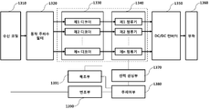
도 13을 참조하면, 무선 전력 수신기(1300)는 수신 코일(1310), 동작 주파수 필터(1320), 디코딩부(1330), 정류부(1340), DC/DC 컨버터(1350), 부하(1360), 전력 센싱부(1370), 주제어부(1380), 변조부(1390) 및 복조부(1391)를 포함하여 구성될 수 있다.13, the radio power receiver 1300 includes a receiving
수신 코일(1310)을 통해 수신된 AC 전력 신호는 동작 주파수 필터(1320)을 통해 동작 주파수 성분이 제거된 후 기저대역으로 변환되어 디코딩부(1330)에 전달될 수 있다. The AC power signal received through the receiving
디코딩부(1330)는 복수의 서로 다른 코드로 인코딩된 신호를 디코딩하기 위한 복수의 제1 내지 제n 디코더를 포함하여 구성될 수 있다.The
디코딩부(1330)에 의해 디코딩된 신호는 정류부(1340)에 전달될 수 있다. The signal decoded by the
정류부(1340)는 디코딩된 AC 전력을 DC 전력으로 변환하여 DC/DC 컨버터(1350)에 전송할 수 있다. DC/DC 컨버터(1350)는 정류기 출력 DC 전력의 세기를 부하(1360)에 요구되는 세기로 변환하여 부하(1360)에 전달할 수 있다.The
전력 센싱부(1370)는 정류부(1340)에 포함된 제1 내지 제n 정류기 각각의 출력 DC 전력의 세기를 측정하고, 이를 주제어부(1380)에 제공할 수 있다.The
일 예로, 주제어부(1380)는 측정된 정류기 출력 DC 전력의 세기가 소정 기준치 이상인 정류기를 식별하고 식별된 정류기에 대응되는 코드를 이용하여 시그널 세기 지시자가 송출될 수 있도록 변조부(1390)를 제어할 수 있다. 상세하게, 주제어부(1380)는 정류기 출력 DC 전력의 세기가 소정 기준치 이상인 경우, 감지 신호가 수신된 것으로 판단할 수 있으며, 감지 신호 수신 시, 해당 감지 신호 전송에 사용된 코드를 이용하여 감지 신호에 대응되는 시그널 세기 지시자가 전송될 수 있도록 변조부(1390)를 제어할 수 있다.For example, the
다른 일 예로, 복조부(1391)는 디코딩부(1330)의 디코더 별 출력을 복조하여 감지 신호의 수신 여부를 식별할 수 있으며, 식별된 감지 신호가 어느 코드로 인코딩되어 전송되었는지에 대한 정보를 주제어부(1380)에 제공할 수 있다. 이때, 주제어부(1380)는 식별된 감지 신호 전송에 사용된 코드와 동일한 코드를 이용하여 시그널 세기 지시자가 변조부(790)를 통해 전송될 수 있도록 제어할 수 있다.In another example, the
도 14는 본 발명의 일 실시예에 따른 송신 코일 별 서로 다른 코드를 이용하여 암호화된 감지 신호를 송출하는 것이 가능한 멀티 코일 무선 전력 송신기에서의 멀티 코일 무선 충전 방법을 설명하기 위한 순서도이다.FIG. 14 is a flowchart illustrating a multi-coil wireless charging method in a multi-coil wireless power transmitter capable of transmitting an encrypted sensing signal using different codes according to an embodiment of the present invention.
도 14를 참조하면, 무선 전력 송신기는 N개의 송신 코일 각각에 할당된 서로 다른 코드로 인코딩된 제1차 감지 신호를 N개의 송신 코일을 통해 동시에 송출할 수 있다(S1401).Referring to FIG. 14, the wireless power transmitter may simultaneously transmit the first differential sensing signals encoded with different codes assigned to the N transmit coils through N transmit coils (S1401).
무선 전력 송신기는 시그널 세기 지시자가 수신된 적어도 하나의 송신 코일을 식별하고, 식별된 적어도 하나의 송신 코일을 통해 전송된 제1차 감지 신호를 인코딩하기 위한 사용되었는 적어도 하나의 코드를 식별할 수 있다(S1403).The wireless power transmitter may identify at least one transmit coil for which the signal strength indicator is received and at least one code that has been used to encode the first transmit signal transmitted over the identified at least one transmit coil (S1403).
무선 전력 송신기는 식별된 적어도 하나의 코드만을 이용하여 인코딩된 제2차 감지 신호를 송출할 수 있다(S1405).The wireless power transmitter may transmit the encoded secondary sense signal using only the identified at least one code (S1405).
무선 전력 송신기는 제2차 감지 신호에 대응하여 수신된 시그널 세기 지시자에 기반하여 수신 전력 세기가 가장 높은 코드를 선택할 수 있다(S1407). 즉, 무선 전력 송신기는 해당 무선 전력 수신기로의 전력 전송에 사용할 송신 코일을 선택된 코드에 기반하여 식별할 수 있다.The wireless power transmitter may select a code having the highest received power based on the received signal strength indicator corresponding to the second detection signal (S1407). That is, the wireless power transmitter can identify a transmit coil to use for power transmission to the wireless power receiver based on the selected code.
무선 전력 송신기는 선택된 코드를 이용하여 전력 신호를 인코딩한 후, 선택된 코드에 대응되는 송신 코일을 이용하여 전력을 송출할 수 있다(S1409).The wireless power transmitter may encode the power signal using the selected code, and then transmit the power using the transmitting coil corresponding to the selected code (S1409).
도 15는 본 발명의 일 실시예에 따른 송신 코일 별 서로 다른 코드를 이용하여 송출된 감지 신호를 수신하는 것이 가능한 무선 전력 수신기에서의 멀티 코일 무선 충전 방법을 설명하기 위한 순서도이다.15 is a flowchart for explaining a multi-coil wireless charging method in a wireless power receiver capable of receiving a sensing signal transmitted using different codes according to an embodiment of the present invention.
도 15를 참조하면, 무선 전력 수신기는 수신 코일을 통해 수신된 특정 동작 주파수 대역의 AC 신호를 구비된 동작 주파수 필터에 통과시켜 기저 대역 신호를 획득할 수 있다(S1501).Referring to FIG. 15, a wireless power receiver can acquire a baseband signal by passing an AC signal of a specific operating frequency band received through a receiving coil to a provided operating frequency filter (S1501).
무선 전력 수신기는 획득된 기저 대역 신호를 제1 내지 n 디코더에 통과시켜, 제1차 감지 신호가 수신된 적어도 하나의 디코더를 식별할 수 있다(S1503).The wireless power receiver may pass the obtained baseband signal to the first through n decoders to identify at least one decoder from which the primary sense signal was received (S1503).
무선 전력 수신기는 수신된 제1차 감지 신호에 대응되는 시그널 세기 지시자를 식별된 디코더에 대응되는 적어도 하나의 코드로 인코딩하여 송출할 수 있다(S1505).The wireless power receiver may encode the signal strength indicator corresponding to the received primary sensed signal into at least one code corresponding to the identified decoder and transmit the encoded signal (S1505).
무선 전력 수신기는 상기 1503 단계에서 식별된 적어도 하나의 디코더를 통해 수신되는 제2차 감지 신호의 세기에 기반하여 전력 수신을 위한 코드를 선택할 수 있다(S1507).The wireless power receiver may select a code for power reception based on the intensity of the second differential sense signal received through the at least one decoder identified in step 1503 (S1507).
무선 전력 수신기는 수신된 제2차 감지 신호에 대응되는 시그널 세기 지시자를 선택된 코드로 인코딩하여 송출할 수 있다(S1509).The wireless power receiver may encode the signal strength indicator corresponding to the received second detection signal with the selected code and transmit the selected signal strength indicator (S1509).
이 후, 무선 전력 수신기는 선택된 코드에 대응되는 디코더를 통해 전력을 수신할 수 있다(S1511). Thereafter, the wireless power receiver may receive power via a decoder corresponding to the selected code (S1511).
도 16은 본 발명의 일 실시예에 따른 복수의 송신 코일이 장착된 무선 전력 전송 시스템을 설명하기 위한 도면이다.16 is a view for explaining a wireless power transmission system equipped with a plurality of transmission coils according to an embodiment of the present invention.
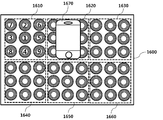
도 16에 도시된 바와 같이, 무선 전력 전송 시스템(1600)의 충전 베드에 장착되는 복수의 송신 코일은 제1 내지 제6 그룹(1610 내지 1660)으로 구성될 수 있다. 이하의 실시예서는 그룹의 개수가 6이고, 각각의 그룹이 9개의 송신 코일(제1 내지 제9 송신 코일)로 구성되는 것을 예를 들어 설명하기로 한다. 하지만, 이는 하나의 실시예에 불과하며, 총 그룹의 개수 및 그룹 별 할당되는 송신 코일의 개수는 무선 전력 전송 시스템(1600)의 구성 형태 및 용도에 따라 상이하게 적용될 수 있음을 주의해야 한다.As shown in FIG. 16, the plurality of transmission coils mounted on the charging bed of the wireless
도 16을 참조하면, 제1 내지 제6 그룹(1610 내지 1660)은 각각 9개의 송신 코일로 구성될 수 있다. 도 16에서는 그룹 내 송신 코일들이 서로 이격되어 배치되는 것으로 도시되어 있으나, 이는 하나의 실시예에 불과하며, 본 발명의 다른 일 실시예에 따른 그룹 내 송신 코일들은 일부 영역이 서로 중첩되도록 배치될 수도 있다.Referring to FIG. 16, each of the first to
무선 전력 전송 시스템(1600)은 그룹 단위의 동작을 제어할 수 있을 뿐만 아니라 그룹 내 송신 코일 단위의 동작을 제어할 수도 있다. 즉, 무선 전력 전송 시스템(1600)은 그룹 내 특정 송신 코일을 통해 전력이 송출될 수 있도록 제어할 수 있다.The wireless
무선 전력 전송 시스템(1600)은 무선 전력 수신 장치(1670)를 식별하기 위한 소정 제1 감지 신호-예를 들면, WPC 또는 PMA 표준의 디지털 핑일 수 있음-를 그룹 단위로 순차적으로 전송할 수 있다. 일 예로, 무선 전력 전송 시스템(1600)은 미리 정해진 순서-예를 들면, 제1 그룹(1610)->제2 그룹(1620)->제3 그룹(1630)->제4 그룹(1640)->제5 그룹(1650)->제6 그룹(1660)-에 따라 순차적으로 그룹 별 제1 감지 신호를 송출할 수 있다. 이때, 제1 감지 신호가 송출되는 송신 코일은 그룹 내 중앙에 위치한 송신 코일일 수 있으나, 이는 하나의 실시예에 불과하며, 제1 감지 신호가 송출되는 송신 코일은 설계자에 의해 변경될 수 있음을 주의해야 한다.The wireless
본 발명의 다른 일 실시예에 따른 무선 전력 전송 시스템(1600)은 무선 전력 수신 장치(1670)를 식별하기 위한 소정 제1 감지 신호가 소정 주기로 모든 그룹에서 동시에 전송될 수 있도록 제어할 수 있다. 이때, 제1 감지 신호의 전송에 사용되는 동작 주파수는 모든 그룹에서 동일하거나 서로 상이할 수 있다. 일 예로, 제1 감지 신호가 전송되는 송신 코일이 그룹 내 중앙에 위치한 송신 코일이고, 제1 감지 신호가 송출되는 송신 코일들이 그룹 간 서로 간섭이 발생되지 않도록 충분히 이격된 경우, 모든 그룹은 동일한 주파수를 이용하여 제1 감지 신호를 송출할 수 있다.The wireless
반면, 제1 감지 신호가 전송되는 송신 코일 간 동일 주파수 간섭이 발생되는 경우, 그룹 별 미리 할당된 서로 다른 주파수를 이용하여 제1 감지 신호가 송출될 수도 있다.On the other hand, when the same frequency interference occurs between the transmission coils to which the first sensing signal is transmitted, the first sensing signal may be transmitted using different pre-allocated frequencies for each group.
본 발명의 또 다른 일 실시예에 따른 무선 전력 전송 시스템(1600)은 무선 전력 수신 장치(1670)를 식별하기 위한 소정 제1 감지 신호를 그룹 별 미리 할당된 소정 코드를 이용하여 인코딩한 후 인코딩된 제1 감지 신호가 특정 동작 주파수를 이용하여 송출되도록 제어할 수도 있다. 이때, 제1 감지 신호의 인코딩에 사용되는 코드는 코드간에 상관성이 없어서 인코딩된 신호들 사이의 간섭을 최소화시키고, 수신단에서의 신호 구분이 용이한 다중화 코드일 수 있으며, 일 예로, 다중화 코드는 직교 코드(Orthogonal code), 왈쉬 코드(Walsh Code)가 사용될 수 있으나 이에 한정되지는 않는다. 직교 코드 또는 왈쉬 코드는 확산 이득을 획득하기 위한 확산 코드로 사용될 수도 있다. 또한, 확산된 신호는 암호화를 위한 소정 PN(Pseudo Noise) 코드로 인코딩될 수도 있다.The wireless
다른 일 예로, 무선 전력 전송 시스템(1600)은 그룹 별 제1 감지 신호가 송출되는 송신 코일을 소정 주기로 변경할 수도 있다. 일 예로, 도면 번호 1610에 도시된 바와 같이, 무선 전력 전송 시스템(1600)은 제1 그룹(1610) 내 중앙에 위치한 송신 코일을 이용해 제1 감지 신호를 송출한 뒤 연이어 제2 내지 제9 송신 코일을 통해 순차적으로 제1 감지 신호를 송출할 수 있다.In another example, the wireless
만약, 제1 감지 신호에 상응하는 시그널 세기 지시자가 수신되면, 무선 전력 전송 시스템(1600)은 제1 감지 신호 송출을 중단하고, 제2 감지 신호 전송 절차를 개시할 수 있다.If a signal strength indicator corresponding to the first sensing signal is received, the wireless
제2 감지 신호 전송 절차 동안, 무선 전력 전송 시스템(1600)은 그룹 내 송신 코일 별 미리 정의된 순서에 따라 제2 감지 신호를 순차적으로 송출할 수 있다. 연이어, 무선 전력 전송 시스템(1600)은 송출된 제2 감지 신호에 대응하여 수신된 시그널 세기 지시자에 기반하여 해당 그룹 내 무선 전력 전송에 사용될 송신 코일을 선택할 수 있다. 이 후, 선택된 송신 코일을 이용하여 해당 무선 전력 수신 장치(1670)를 위한 무선 충전이 이루어질 수 있다.During the second sensing signal transmission procedure, the wireless
본 발명의 다른 일 실시예에 따른 무선 전력 전송 시스템(1600)은 그룹 별 또는 서브 무선 전력 송신기 별 송출된 제1 감지 신호에 대응하여 수신된 제1 시그널 세기 지시자가 복수개인 경우-즉, 복수의 그룹 또는 서브 무선 전력 송신기로부터 제1 시그널 세기 지시자가 수신된 경우-, 제1 시그널 세기 지시자에 기반하여 그룹 또는 서브 무선 전력 송신기 사이의 제2 감지 신호 송출 순서를 결정할 수도 있다. 일 예로, 수신된 제1 시그널 세기 지시가가 큰 값을 가질수록-즉, 무선 전력 수신기의 수신 전력 세기가 클수록- 제2 감지 신호가 송출되는 순서가 앞서도록 결정될 수 있다.The wireless
무선 전력 전송 시스템(1600)은 제1 감지 신호 및 제2 감지 신호의 송출 주기, 송출 시간 및 출력 전압 세기 등을 제어할 수도 있다.The wireless
일 예로, 제1 감지 신호 및 제2 감지 신호의 송출 주기, 송출 시간 및 출력 전압 세기는 동일할 수 있다. 다른 일 예로, 제1 감지 신호와 제2 감지 신호의 송출 주기, 송출 시간 및 출력 전압 세기 중 적어도 하나가 서로 상이하도록 제어될 수도 있다.For example, the transmission period, the transmission time, and the output voltage intensity of the first sensing signal and the second sensing signal may be the same. In another example, at least one of the transmission period, the transmission time, and the output voltage intensity of the first sensing signal and the second sensing signal may be controlled to be different from each other.
도 17은 본 발명의 일 실시예에 따른 무선 전력 전송 시스템에서의 제1 감지 신호 전송 절차를 설명하기 위한 도면이다.17 is a diagram for explaining a first sensing signal transmission procedure in a wireless power transmission system according to an embodiment of the present invention.
도 17을 참조하면, 무선 전력 전송 시스템(1600)은 그룹 별 중앙에 위치한 송신 코일을 이용하여 출력 전압 세기가 제1 출력 전압 세기(v1)이고, 송출 주기가 제1 감지 신호 전송 주기(t_period_first_detection_signal)이고, 송출 시간이 제1 감지 신호 전송 시간(t_duration_first_detection_signal)인 제1 감지 신호를 송출할 수 있다. 17, the wireless
무선 전력 전송 시스템(1600)은 제1 감지 신호 전송 절차를 수행하는 동안, 무선 전력 수신 장치로부터 시그널 세기 지시자가 수신된 그룹을 식별할 수 있다.The wireless
무선 전력 전송 시스템(1600)은 시그널 세기 지시자가 수신된 그룹이 존재하는 경우, 해당 그룹 내 송신 코일들을 이용하여 제2 감지 신호 전송 절차를 개시할 수 있다. 물론, 무선 전력 전송 시스템(1600)은 제1 감지 신호에 대응되는 시그널 세기 지시자가 수신되지 않은 그룹에 대하여 제1 감지 신호 전송 절차가 계속해서 수행되도록 제어할 수 있다.The wireless
도 18은 본 발명의 일 실시예에 따른 무선 전력 전송 시스템에서의 제2 감지 신호 전송 절차를 설명하기 위한 도면이다.18 is a diagram for explaining a second sensing signal transmission procedure in a wireless power transmission system according to an embodiment of the present invention.
도 18에 도시된 실시예는 제1 그룹의 제1 송신 코일을 통해 송출된 제1 감지 신호에 대응하여 시그널 세기 지시자가 수신된 경우, 무선 전력 전송 시스템(1600)이 제2 감지 신호를 전송하는 방법을 상세히 설명하나, 이는 하나의 실시예에 불과하며, 시그널 세기 지시자가 수신되는 그룹은 무선 전력 수신 장치가 충전 영역에 놓여진 위치에 따라 상이할 수 있음은 자명하다.18, when the signal strength indicator is received corresponding to the first sensing signal transmitted through the first transmission coil of the first group, the wireless
도 18을 참조하면, 무선 전력 전송 시스템은 제1 송신 코일을 통해 송출된 제1 감지 신호에 대응되는 시그널 세기 지시자가 수신된 경우, 제1 그룹의 송신 코일들을 이용한 제2 감지 신호 전송 절차를 개시할 수 있다. 이때, 제1 그룹 내 송신 코일들의 제2 감지 신호 전송 순서는 도 18의 도면 번호 1610에 보여지는 번호순으로 결정될 수 있으나, 이는 하나의 실시예에 불과하며 그룹 내 송신 코일들을 이용한 제2 감지 신호 전송 순서는 구현에 따라 상이하게 결정될 수도 있음을 주의해야 한다.Referring to FIG. 18, when the signal strength indicator corresponding to the first sensing signal transmitted through the first transmission coil is received, the wireless power transmission system starts the second sensing signal transmission procedure using the first group of transmission coils can do. At this time, the second sensing signal transmission order of the first-group transmitting coils may be determined by the order shown in the
무선 전력 전송 시스템은 미리 정의된 제2 감지 신호 전송 순서에 따라 송신 코일 별 제2 감지 신호의 출력 전압 세기가 제2 출력 전압 세기(v2)이고, 송출 주기가 제2 감지 신호 전송 시간(t_period_second_detection_signal)이고, 송출 시간이 제2 감지 신호 전송 주기(t_duration_second_detection_signal)인 제2 감지 신호를 송출할 수 있다.The wireless power transmission system may be configured such that the output voltage intensity of the second sensing signal per transmission coil is the second output voltage intensity v2 and the transmission period is the second sensing signal transmission time t_period_second_detection_signal according to the predefined second sensing signal transmission sequence, , And the second sensing signal having the transmission time of the second sensing signal transmission period (t_duration_second_detection_signal) can be transmitted.
도 19는 본 발명의 다른 일 실시예에 따른 무선 전력 전송 시스템에서의 그룹 별 송신 코일 배치 방법을 설명하기 위한 도면이다.FIG. 19 is a diagram for explaining a group-by-group transmission coil arrangement method in a wireless power transmission system according to another embodiment of the present invention.
도 19를 참조하면, 무선 전력 전송 시스템(1900)의 송신 코일들은 제1 내지 제6 그룹(1910 내지 1960)으로 구성될 수 있으며, 각각의 그룹에 포함된 송신 코일들은 일정 영역이 서로 중첩되도록 배치될 수 있다. 그룹 별 송신 코일의 중첩 배치는 보다 정밀하게 송신 코일과 수신 코일을 정렬시킬 수 있는 장점이 있다.Referring to FIG. 19, the transmission coils of the wireless
도 19에 도시된 송신 코일 배치 방법은 차량 무선 충전 시스템에 적용될 수 있으나, 이에 한정되지는 않으며, 다른 분야에도 적용될 수 있음을 주의해야 한다.It should be noted that the transmission coil placement method shown in Fig. 19 can be applied to a vehicle wireless charging system, but is not limited thereto, and can be applied to other fields as well.
도 19를 참조하면, 무선 전력 수신 장치 및 충전용 배터리가 탑재된 차량(1970)은 무선 전력 전송 시스템(1900)에 의해 송출되는 전력을 수신하여 배터리 충전을 수행할 수 있다.Referring to FIG. 19, a
도 19에 도시된 바와 같이, 무선 전력 전송 시스템(1900)은 소정 주기로 제1 감지 신호를 그룹 별 송출하여 차량의 충전 영역으로의 진입 여부를 확인할 수 있다. 이때, 그룹 별 제1 감지 신호를 송출하는 송신 코일은 차량 진입로에 근접한 송신 코일일 수 있으나, 이에 한정되지는 않으며, 차량의 충전 영역으로의 진입 속도, 일반적으로 차량 내 무선 전력 수신 장치의 장착 위치 등에 따라 상이하게 결정될 수 있다.As shown in FIG. 19, the wireless
본 발명의 다른 일 실시예에 따른 무선 전력 전송 시스템(1900)의 일측에는 차량 타이어에 의한 압력을 감지하는 압력 감지 센서가 구비될 수 있다. 이 경우, 무선 전력 전송 시스템(1900)은 압력 감지 센서의 센싱 결과에 기반하여 충전 영역 내 차량의 위치를 감지할 수 있으며, 감지된 차량 위치에 대응되는 송신 코일을 이용하여 감지 신호가 송출되도록 제어할 수도 있다. 따라서, 불필요한 송신 코일을 통해 감지 신호가 송출되어 전력이 낭비되는 것을 미연에 방지할 수 있다. 상세하게, 무선 전력 전송 시스템(1900)은 기준치 이상의 압력이 감지되는 위치 정보-즉, 차량 네 바퀴의 위치 정보일 수 있음-를 압력 감지 센서를 통해 수신할 수 있으며, 수신된 위치 정보에 기반하여 감지 신호를 송출할 송신 코일을 선택할 수 있다.In the wireless
일 예로, 충전 영역 내 차량의 위치를 식별하기 위한 압력 감지 센서는 압력 변화에 따라 전기적 신호를 발생시키는 피에조 케이블(Piezo Cable)이 사용될 수 있으나 이에 한정되지는 않는다. 피에조 케이블은 다양한 형상 및 형태의 설치가 가능한 동축 케이블 형태일 수 있으나 이에 한정되지는 않는다. For example, the pressure sensing sensor for identifying the position of the vehicle in the charging area may be a piezo cable that generates an electrical signal in response to a pressure change, but the present invention is not limited thereto. The piezo cable may be in the form of a coaxial cable capable of being installed in various shapes and forms, but is not limited thereto.
본 발명의 다른 일 실시예에 따른 무선 전력 전송 시스템(1900)은 차량이 진입하는 입구 일측에 차량 진입 여부를 감지하는 소정 차량 감지 센서가 구비될 수도 있다. 이때, 차량 감지 센서에 의해 충전 영역으로의 차량 진입이 감지되면, 무선 전력 전송 시스템(1900)은 감지 신호 송출을 개시할 수도 있다. 이때, 감지 신호는 상기 압력 감지 센서의 센싱 결과에 기반하여 선택된 송신 코일을 이용하여 송출될 수 있다.The wireless
본 발명의 다른 일 실시예에 따른 무선 전력 전송 시스템(1900)은 압력 감지 센서로부터 기준치 이상의 압력이 감지된 충전 영역상의 위치 정보 소정 주기로 수신할 수도 있다. 무선 전력 전송 시스템(1900)은 소정 시간 동안 기준치 이상의 압력이 감지되는 위치가 변경되지 않는 경우, 차량이 완전히 정차한 것으로 판단할 수 있다. 차량이 완전히 정차한 것으로 판단되면, 무선 전력 전송 시스템(1900)은 현재 차량의 정차 위치에 대응되는 송신 코일을 이용하여 감지 신호 전송 절차를 개시하고, 수신된 시그널 세기 지시자에 기반하여 무선 충전을 위해 사용할 송신 코일을 선택할 수 있다.The wireless
무선 전력 전송 시스템(1900)은 제1 감지 신호에 대응되는 제1 시그널 세기 지시자가 수신된 그룹을 식별하고, 식별된 그룹 내 송신 코일들을 이용하여 해당 차량의 배터리 충전을 위해 최적인 송신 코일을 선택하기 위한 제2 감지 신호를 송출할 수 있다. 일 예로, 제2 감지 신호는 좌측에서 우측으로 순차적으로 송출되거나, 우측에서 좌측으로 순차적으로 송출될 수 있다. The wireless
무선 전력 전송 시스템(1900)은 제2 감지 신호에 대응되는 제2 시그널 세기 지시자가 수신된 송신 코일(들)을 식별하고, 식별된 송신 코일(들) 중 적어도 하나를 이용하여 차량 충전을 개시할 수 있다. 물론, 제2 시그널 세기 지시자가 소정 기준치 이상인 송신 코일(들)을 이용하여 차량 충전이 이루어질 수 있다.The wireless
도 19에 도시된 바와 같이, 차종에 따라 무선 전력 수신 장치가 장착된 위치 및 무선 전력 수신 장치의 배치 형태 등이 상이할 수 있다. 따라서, 차종 별 무선 충전을 위해 동시에 사용될 수 있는 송신 코일의 개수는 상이할 수 있다. 따라서, 본 발명의 일 실시예에 따른 무선 전력 전송 시스템(1900)은 그룹 별 제2 감지 신호에 대응하여 수신된 제2 시그널 지시자에 기반하여 해당 차량의 무선 충전에 사용될 송신 코일(들)의 개수를 동적으로 결정할 수 있다.As shown in FIG. 19, the position where the wireless power receiving apparatus is mounted and the arrangement type of the wireless power receiving apparatus may be different depending on the type of vehicle. Thus, the number of transmit coils that can be used simultaneously for wireless charging by vehicle type may be different. Accordingly, the wireless
도 20은 본 발명의 일 실시예에 따른 무선 전력 전송 시스템의 구성을 설명하기 위한 블록도이다.20 is a block diagram illustrating a configuration of a wireless power transmission system according to an embodiment of the present invention.
도 20을 참조하면, 무선 전력 전송 시스템(2000)은 제1 내지 제n 서브 무선 전력 송신기(2010) 및 제1 내지 제n 서브 무선 전력 송신기의 동작을 제어하기 위한 주제어부(2020)를 포함하여 구성될 수 있다.20, the wireless
각각의 서브 무선 전력 송신기는 서브 제어기(2011), 전력변환부(2012), 전력전송부(2013), 변복조부(2014)를 포함하여 구성될 수 있다.Each of the sub wireless power transmitters may include a sub-controller 2011, a
서브 제어기(2011)는 주제어부(2020)의 제어에 따라 서브 무선 전력 송신기의 전체적인 동작을 제어한다. 특히, 서브 제어기(2011)는 전력변환부(2012)를 제어하여 제1 감지 신호 및 제2 감지 신호의 출력 전압 세기, 전송 주기, 전송 시간 등을 제어할 수도 있다. 또한, 서브 제어기(2011)는 변복조부(2014)에 의해 복조된 신호를 수신하거나, 변복조부(2014)에 무선 전력 수신 장치에 전송할 신호를 전송할 수 있다.The sub-controller 2011 controls the overall operation of the sub-radio power transmitter under the control of the
변복조부(2014)는 무선 전력 전송에 이용되는 동일한 주파수 대역을 이용하여 무선 전력 수신 장치와 통신-즉, 인밴드 통신-을 수행하거나, 무선 전력 전송에 이용되는 주파수 대역과 상이한 주파수 대역을 이용하여 무선 전력 수신 장치와 통신-즉, 대역외 통신-을 수행할 수 있다. 일 예로, 대역외 통신은 블루투스 통신, RFID 통신, Zigbee 통신, UWB 통신, WiFi 통신 등을 포함할 수 있으나, 이에 한정되지는 않는다.
주제어부(2020)는 제1 내지 제n 서브 무선 전력 송신기(2010)가 순차적으로 또는 동시에 제1 감지 신호를 전송하도록 제어할 수 있다.The
주제어부(2020)는 서브 무선 전력 송신기 별 송출된 제1 감지 신호에 대응하여 제1 시그널 세기 지시자가 수신되었는지 확인하고, 확인 결과에 기반하여 제2 감지 신호를 전송할 서브 무선 전력 송신기를 결정할 수 있다.The
각각의 서브 무선 전력 송신기는 복수의 송신 코일이 구비될 수 있으며, 주제어부(2020)는 각각의 서브 무선 전력 송신기에 탑재된 복수의 송신 코일을 그룹으로 관리할 수 있다. 그룹 별 제1 감지 신호가 송출되는 송신 코일 및 그룹 내 송신 코일들의 제2 감지 신호 전송 순서는 미리 정의되어 각 서브 무선 전력 송신기의 서브 제어기(2011)에 유지될 수 있다.Each sub wireless power transmitter may be provided with a plurality of transmission coils and
다른 일 예로, 주제어부(2020)는 그룹 별 또는 서브 무선 전력 송신기 별 송출된 제1 감지 신호에 대응하여 수신된 제1 시그널 세기 지시자가 복수개인 경우-즉, 복수의 그룹 또는 서브 무선 전력 송신기로부터 제1 시그널 세기 지시자가 수신된 경우-, 제1 시그널 세기 지시자에 기반하여 그룹 또는 서브 무선 전력 송신기 사이의 제2 감지 신호 송출 순서를 결정할 수도 있다. 일 예로, 수신된 제1 시그널 세기 지시가가 큰 값을 가질수록-즉, 무선 전력 수신기의 수신 전력 세기가 클수록- 제2 감지 신호가 송출되는 순서가 앞서도록 결정될 수 있다.As another example, the
주제어부(2020)는 제2 감지 신호를 전송할 서브 무선 전력 송신기가 결정되면, 제2 감지 신호 전송 절차의 개시를 알리는 소정 제어 신호를 해당 서브 무선 전력 송신기의 서브 제어기(2011)에 전송할 수 있다.When the sub wireless power transmitter to transmit the second sensing signal is determined, the
이때, 서브 제어기(2011)는 미리 정의된 제2 감지 신호 전송 순서에 따라 제2 감지 신호가 전송되도록 전력변환부(2012) 및 전력전송부(2013)를 제어할 수 있다.At this time, the sub-controller 2011 can control the
서브 제어기(2011)는 송출된 제2 감지 신호에 대응하여 제2 시그널 세기 지시자가 수신되면, 수신된 제2 시그널 세기 지시자에 기반하여 전력 전송에 사용할 적어도 하나의 송신 코일을 선택할 수 있다. 이 후, 서브 제어기(2011)는 선택 결과가 포함된 소정 제어 신호를 주제어부(2020)에 전송할 수 있다.When the second signal strength indicator is received in response to the transmitted second sensing signal, the sub-controller 2011 may select at least one transmission coil to be used for power transmission based on the received second signal strength indicator. Subsequently, the sub-controller 2011 can transmit a predetermined control signal including the selection result to the
주제어부(2020)는 서브 제어기(2011)로부터 수신된 무선 전력 수신 장치의 각종 상태 정보 및(또는) 상기 선택 결과에 기반하여 적응적으로 전력변화부(2011)에 공급할 전력량 또는 전력 세기를 결정할 수 있으며, 결정된 전력량 또는 전력의 세기에 상응하는 전력을 전력변환부(2011)에 공급할 수 있다.The
본 발명의 일 실시예에 따른 제1 내지 제n 서브 무선 전력 송신기(2010)는 주제어부(2020)의 제어에 따라 병렬로 구동될 수 있다. 즉, 무선 전력 전송 시스템(2000)은 동시에 복수의 무선 전력 수신 장치를 위한 전력을 송출하여 멀티 충전을 수행할 수도 있다.The first to nth sub
또한, 본 발명의 일 실시예에 따른 서브 무선 전력 송신기 별 전력전송부(2013)에 구비되는 송신 코일의 개수 및(또는) 배치 형태는 서로 상이할 수도 있다.Further, the number and / or arrangement of transmission coils provided in the power transmission unit 2013 for each sub wireless power transmitter according to an embodiment of the present invention may be different from each other.
또한, 본 발명의 일 실시예에 따른 서브 무선 전력 송신기 별 제1 감지 신호 및(또는) 제2 감지 신호 전송에 사용되는 주파수는 서로 상이할 수도 있다.In addition, the frequencies used for transmitting the first sensing signal and / or the second sensing signal may be different from each other according to the embodiment of the present invention.
또한, 본 발명의 일 실시예에 따른 서브 무선 전력 송신기 별 제1 감지 신호 및(또는) 제2 감지 신호의 인코딩에 사용되는 코드는 서로 상이할 수 있다.Also, the codes used for encoding the first sensing signal and / or the second sensing signal for each sub wireless power transmitter according to an embodiment of the present invention may be different from each other.
또한, 본 발명의 일 실시예에 따른 제1 내지 제n 서브 무선 전력 송신기(2010)는 미리 정의된 순서로 제1 감지 신호를 전송하거나, 동시에 제1 감지 신호를 소정 주기로 전송할 수 있다.In addition, the first to nth sub
도 21은 본 발명의 일 실시예에 따른 복수의 송신 코일이 구비된 무선 전력 전송 시스템에서의 멀티 코일 무선 충전 방법을 설명하기 위한 순서도이다.21 is a flowchart for explaining a multi-coil wireless charging method in a wireless power transmission system having a plurality of transmission coils according to an embodiment of the present invention.
도 21을 참조하면, 무선 전력 전송 시스템은 n개의 그룹에 복수의 송신 코일을 할당할 수 있다(S2101). 이때, 그룹 별 할당되는 송신 코일의 개수 및 배치 형태는 동일할 수 있으나, 이는 하나의 실시예에 불과하며, 본 발명의 다른 일 실시예는 그룹 별 할당되는 송신 코일의 개수, 그룹 별 할당된 송신 코일의 배치 형태 중 적어도 하나가 서로 상이할 수도 있음을 주의해야 한다.Referring to FIG. 21, a wireless power transmission system can allocate a plurality of transmission coils to n groups (S2101). In this case, the number and the arrangement type of the transmission coils to be allocated to each group may be the same, but this is only one embodiment. In another embodiment of the present invention, the number of transmission coils allocated to each group, It should be noted that at least one of the arrangement of the coils may be different from each other.
무선 전력 전송 시스템은 그룹 별 지정된 소정 송신 코일을 이용하여 순차적으로 제1 감지 신호를 송출할 수 있다(S2103). 다른 일 예로, 무선 전력 전송 시스템은 그룹 별 지정된 소정 송신 코일을 이용하여 동시에 제1 감지 신호를 송출할 수도 있음을 주의해야 한다. 이때, 제1 감지 신호 송출에 사용되는 주파수는 각 그룹 별 상이할 수도 있음을 주의해야 한다.The wireless power transmission system may sequentially transmit the first sensing signal using a predetermined transmission coil designated for each group (S2103). It should be noted that as another example, the wireless power transmission system may simultaneously transmit the first sensing signal using the predetermined transmission coil designated for each group. It should be noted that the frequency used for transmitting the first sensing signal may be different for each group.
무선 전력 전송 시스템은 그룹 별 송출된 제1 감지 신호에 대응하여 제1 시그널 지시자가 수신된 그룹을 식별할 수 있다(S2105). 이때, 식별된 그룹의 개수는 복수 개일 수도 있음을 주의해야 한다.The wireless power transmission system can identify the group in which the first signal indicator is received in response to the first sensing signal transmitted in each group (S2105). It should be noted that the number of groups identified may be plural.
무선 전력 전송 시스템은 식별된 그룹 내 할당된 송신 코일을 이용하여 제2 감지 신호를 송출할 수 있다(S2107). 일 예로, 무선 전력 전송 시스템은 미리 정의된 송신 코일 순서로 제2 감지 신호가 송출되도록 제어할 수도 있다.The wireless power transmission system may transmit the second sensing signal using the assigned transmitting coil in the identified group (S2107). In one example, the wireless power transmission system may control to send the second sensing signal in a predefined transmit coil sequence.
무선 전력 전송 시스템은 송출된 제2 감지 신호에 대응하여 수신된 제2 시그널 세기 지시자에 기반하여 해당 그룹 별 전력 전송에 사용할 송신 코일을 선택할 수 있다(S2109).In step S2109, the wireless power transmission system may select a transmission coil to be used for power transmission for each group based on the received second signal strength indicator corresponding to the transmitted second sensing signal.
이 후, 무선 전력 전송 시스템은 선택된 송신 코일을 이용하여 무선 충전을 수행할 수 있다(S2111).Thereafter, the wireless power transmission system can perform wireless charging using the selected transmission coil (S2111).
상술한 실시예에 따른 방법은 컴퓨터에서 실행되기 위한 프로그램으로 제작되어 컴퓨터가 읽을 수 있는 기록 매체에 저장될 수 있으며, 컴퓨터가 읽을 수 있는 기록 매체의 예로는 ROM, RAM, CD-ROM, 자기 테이프, 플로피디스크, 광 데이터 저장장치 등이 있으며, 또한 캐리어 웨이브(예를 들어 인터넷을 통한 전송)의 형태로 구현되는 것도 포함한다.The method according to the above-described embodiments may be implemented as a program to be executed by a computer and stored in a computer-readable recording medium. Examples of the computer-readable recording medium include a ROM, a RAM, a CD- , A floppy disk, an optical data storage device, and the like, and may also be implemented in the form of a carrier wave (for example, transmission over the Internet).
컴퓨터가 읽을 수 있는 기록 매체는 네트워크로 연결된 컴퓨터 시스템에 분산되어, 분산방식으로 컴퓨터가 읽을 수 있는 코드가 저장되고 실행될 수 있다. 그리고, 상술한 방법을 구현하기 위한 기능적인(function) 프로그램, 코드 및 코드 세그먼트들은 실시예가 속하는 기술분야의 프로그래머들에 의해 용이하게 추론될 수 있다.The computer readable recording medium may be distributed over a networked computer system so that computer readable code can be stored and executed in a distributed manner. And, functional program, code, and code segments for implementing the above-described method can be easily inferred by programmers in the technical field to which the embodiment belongs.
본 발명은 본 발명의 정신 및 필수적 특징을 벗어나지 않는 범위에서 다른 특정한 형태로 구체화될 수 있음은 당업자에게 자명하다. It will be apparent to those skilled in the art that the present invention may be embodied in other specific forms without departing from the spirit or essential characteristics thereof.
따라서, 상기의 상세한 설명은 모든 면에서 제한적으로 해석되어서는 아니되고 예시적인 것으로 고려되어야 한다. 본 발명의 범위는 첨부된 청구항의 합리적 해석에 의해 결정되어야 하고, 본 발명의 등가적 범위 내에서의 모든 변경은 본 발명의 범위에 포함된다.Accordingly, the above description should not be construed in a limiting sense in all respects and should be considered illustrative. The scope of the present invention should be determined by rational interpretation of the appended claims, and all changes within the scope of equivalents of the present invention are included in the scope of the present invention.
417, 427, 517, 527: 시그널 세기 지시자(Signal Strength Indicator)
418, 428, 518, 528: 감지 신호(Detection Signal)
600: 무선 전력 송신기
700: 무선 전력 수신기
610: 전력 변환부
620: 전력 전송부
630: 변조부
640: 제어부
2000: 무선 전력 전송 시스템
2010: 제1 내지 제n 서브 무선 전력 송신기
2020: 주제어부417, 427, 517, 527: Signal Strength Indicator
418, 428, 518, 528: Detection signal
600: Wireless power transmitter
700: Wireless power receiver
610: Power conversion unit
620:
630:
640:
2000: Wireless Power Transmission System
2010: First to nth sub wireless power transmitters
2020:
Claims (31)
각각 복수의 송신 코일이 구비되며, 제1 감지 신호를 송출하는 제1 내지 제n 서브 무선 전력 송신기; 및
상기 제1 감지 신호에 대응하는 제1 시그널 세기 지시자의 수신 여부에 기반하여 제2 감지 신호를 송출할 서브 무선 전력 송신기를 식별하는 주제어부
를 포함하는, 무선 전력 전송 시스템.1. A wireless power transmission system comprising a plurality of transmission coils,
First to nth sub wireless power transmitters each having a plurality of transmission coils and transmitting a first sensing signal; And
A main controller for identifying a sub wireless power transmitter to transmit a second sensing signal based on whether or not a first signal strength indicator corresponding to the first sensing signal is received,
Gt; power transmission system. ≪ / RTI >
상기 주제어부가 상기 제1 감지 신호에 대응하는 상기 제1 시그널 세기 지시자가 수신된 상기 서브 무선 전력 송신기를 통해 상기 제2 감지 신호가 송출되도록 제어하는, 무선 전력 전송 시스템.The method according to claim 1,
And the main control unit controls the second sensing signal to be transmitted through the sub wireless power transmitter in which the first signal strength indicator corresponding to the first sensing signal is received.
상기 제1 감지 신호는 상기 서브 무선 전력 송신기에 배치된 상기 복수의 송신 코일 중 특정 하나의 송신 코일을 통해 소정 주기로 송출되는, 무선 전력 전송 시스템.The method according to claim 1,
Wherein the first sensing signal is transmitted at a predetermined cycle through a specific one of the plurality of transmission coils disposed in the sub wireless power transmitter.
상기 특정 하나의 송신 코일은 상기 배치된 복수의 송신 코일 중 중앙에 배치된 송신 코일인, 무선 전력 전송 시스템.The method of claim 3,
Wherein the particular one of the transmit coils is a centrally located transmit coil of the plurality of transmit coils disposed.
상기 제1 감지 신호는 상기 제1 내지 제n 서브 무선 전력 송신기에서 소정 주기로 동시에 송출되는, 무선 전력 전송 시스템.The method according to claim 1,
And wherein the first sensing signal is simultaneously transmitted from the first through the nth sub wireless power transmitters at predetermined intervals.
상기 제1 내지 제n 서브 무선 전력 송신기 별 할당된 서로 다른 주파수를 이용하여 상기 제1 감지 신호가 동시에 송출되는, 무선 전력 전송 시스템.6. The method of claim 5,
And the first sensing signals are simultaneously transmitted using different frequencies assigned to the first through the nth sub wireless power transmitters.
상기 제1 내지 제n 서브 무선 전력 송신기 별 할당된 서로 다른 코드를 이용하여 상기 제1 감지 신호가 동시에 송출되는, 무선 전력 전송 시스템.6. The method of claim 5,
Wherein the first sensing signal is simultaneously transmitted using different codes assigned to the first through the nth sub wireless power transmitters.
상기 코드는 직교 다중화가 가능한 다중화 코드를 포함하는, 무선 전력 전송 시스템.8. The method of claim 7,
Wherein the code comprises a multiplexed code capable of orthogonal multiplexing.
상기 제1 감지 신호는 상기 제1 내지 제n 서브 무선 전력 송신기에서 미리 정의된 순서에 따라 전송되는, 무선 전력 전송 시스템.The method according to claim 1,
Wherein the first sensing signal is transmitted in a predefined order in the first through nth sub wireless power transmitters.
상기 제1차 감지 신호 및 상기 제2차 감지 신호는 WPC 표준 또는 PMA 표준에 정의된 디지털 핑 신호인, 무선 전력 전송 시스템.The method according to claim 1,
Wherein the first differential sense signal and the second differential sense signal are digital dip signals defined in a WPC standard or a PMA standard.
상기 제2 감지 신호는 상기 식별된 서브 무선 전력 송신기내에 구비된 복수의 송신 코일에 대응하여 미리 정의된 순서에 기반하여 순차적으로 송출되는, 무선 전력 전송 시스템.The method according to claim 1,
Wherein the second sensing signal is transmitted sequentially based on a predefined sequence corresponding to a plurality of transmit coils provided in the identified sub wireless power transmitter.
상기 식별된 서브 무선 전력 송신기가 복수개인 경우, 상기 식별된 서브 무선 전력 송신기 사이에서의 상기 제2 감지 신호의 송출 순서는 상기 제1 시그널 세기 지시자에 기반하여 결정되는, 무선 전력 전송 시스템.12. The method of claim 11,
And when the identified sub wireless power transmitters are plural, a transmission order of the second sense signal between the identified sub wireless power transmitters is determined based on the first signal strength indicator.
상기 제1 감지 신호와 상기 제2 감지 신호의 출력 전압 세기, 전송 주기 및 전송 시간 중 적어도 하나가 서로 상이한 것을 특징으로 하는, 무선 전력 전송 시스템.The method according to claim 1,
Wherein at least one of an output voltage intensity, a transmission period, and a transmission time of the first sensing signal and the second sensing signal is different from each other.
상기 식별된 서브 무선 전력 송신기가 송출한 상기 제2 감지 신호에 대응하여 수신된 제2 시그널 세기 지시자에 기반하여 전력 전송에 사용할 적어도 하나의 송신 코일을 선택하는, 무선 전력 전송 시스템.The method according to claim 1,
And selects at least one transmit coil to use for power transmission based on a second signal strength indicator received corresponding to the second sense signal issued by the identified sub wireless power transmitter.
각각의 상기 제1 내지 제n 서브 무선 전력 송신기는 무선 전력 수신기와의 통신을 수행하는 서브 제어기를 더 포함하되, 상기 주제어부가 상기 서브 제어기로부터 수신된 상기 무선 전력 수신기의 상태 정보 및 상기 선택된 송신 코일에 관한 정보에 기반하여 상기 식별된 서브 무선 전력 송신기에 전송할 전력의 세기를 결정하는, 무선 전력 전송 시스템.The method according to claim 1,
Wherein each of the first through the nth sub wireless power transmitters further comprises a sub-controller for performing communication with a wireless power receiver, wherein the main control unit transmits status information of the wireless power receiver received from the sub- To determine the strength of the power to send to the identified sub-radio power transmitter based on information about the identified sub-radio power transmitter.
n개의 그룹에 상기 그룹 별 복수의 송신 코일을 할당하는 단계-여기서, n은 자연수-;
상기 그룹 별 제1 감지 신호를 주기적으로 송출하는 단계;
송출된 상기 제1 감지 신호에 대응하여 제1 시그널 세기 지시자가 수신된 그룹을 식별하는 단계;
식별된 상기 그룹 내 할당된 복수의 송신 코일을 이용하여 제2 감지 신호를 송출하는 단계; 및
송출된 상기 제2 감지 신호에 대응하여 수신된 제2 시그널 세기 지시자에 기반하여 상기 식별된 그룹 별 전력 전송에 사용할 적어도 하나의 송신 코일을 선택하는 단계
를 포함하는, 멀티 코일 무선 전력 전송 방법.1. A method for transmitting a multi-coil wireless power in a wireless power transmission system having a plurality of transmission coils,
allocating a plurality of transmission coils per group to n groups, where n is a natural number;
Periodically transmitting the first sensing signal per group;
Identifying a group in which the first signal strength indicator is received in response to the transmitted first sensing signal;
Transmitting a second sensing signal using a plurality of the plurality of transmission coils allocated in the identified group; And
Selecting at least one transmission coil to be used for power transmission per identified group based on the second signal strength indicator received corresponding to the transmitted second sensing signal
/ RTI > The method of claim 1, wherein the multi-coil wireless power transmission method comprises:
상기 제1 감지 신호는 상기 그룹 별 할당된 복수의 송신 코일 중 특정 하나의 송신 코일을 통해 소정 주기로 송출되는, 멀티 코일 무선 전력 전송 방법.17. The method of claim 16,
Wherein the first sensing signal is transmitted at a predetermined cycle through a specific one of a plurality of transmission coils allocated to each group.
상기 특정 하나의 송신 코일은 상기 그룹 별 상기 무선 전력 전송 시스템에 배치된 복수의 송신 코일 중 중앙에 배치된 송신 코일인, 멀티 코일 무선 전력 전송 방법.18. The method of claim 17,
Wherein the one particular transmission coil is a centrally located transmit coil among a plurality of transmit coils disposed in the group-by-group wireless power transmission system.
상기 제1 감지 신호는 상기 n개의 그룹에 대응되는 제1 내지 제n 서브 무선 전력 송신기에서 소정 주기로 동시에 송출되는, 멀티 코일 무선 전력 전송 방법.17. The method of claim 16,
Wherein the first sensing signal is simultaneously transmitted from the first through the nth sub wireless power transmitters corresponding to the n groups at predetermined intervals.
상기 제1 내지 제n 서브 무선 전력 송신기 별 할당된 서로 다른 주파수를 이용하여 상기 제1 감지 신호가 동시에 송출되는, 멀티 코일 무선 전력 전송 방법.20. The method of claim 19,
Wherein the first sensing signal is simultaneously transmitted using different frequencies assigned to the first through the nth sub wireless power transmitters.
상기 제1 내지 제n 서브 무선 전력 송신기 별 할당된 서로 다른 코드를 이용하여 상기 제1 감지 신호가 동시에 송출되는, 멀티 코일 무선 전력 전송 방법.20. The method of claim 19,
Wherein the first sensing signal is simultaneously transmitted using different codes assigned to the first through the nth sub wireless power transmitters.
상기 코드는 직교 다중화가 가능한 다중화 코드를 포함하는, 멀티 코일 무선 전력 전송 방법.22. The method of claim 21,
Wherein the code comprises a multiplexed code capable of orthogonal multiplexing.
상기 제1 감지 신호는 상기 그룹 별 할당된 복수의 송신 코일에 상응하여 미리 정의된 순서에 기반하여 전송되는, 멀티 코일 무선 전력 전송 방법.17. The method of claim 16,
Wherein the first sensing signal is transmitted based on a predefined sequence corresponding to a plurality of transmission coils assigned to the group.
상기 제1차 감지 신호 및 상기 제2차 감지 신호는 WPC 표준 또는 PMA 표준에 정의된 디지털 핑 신호인, 멀티 코일 무선 전력 전송 방법.17. The method of claim 16,
Wherein the first differential signal and the second differential signal are digital dip signals defined in a WPC standard or a PMA standard.
상기 제2 감지 신호는 상기 식별된 그룹에 할당된 복수의 송신 코일에 상응하여 미리 정의된 순서에 기반하여 송출되는, 멀티 코일 무선 전력 전송 방법.17. The method of claim 16,
Wherein the second sense signal is sent based on a predefined sequence corresponding to a plurality of transmit coils assigned to the identified group.
상기 식별된 그룹이 복수개인 경우, 상기 식별된 그룹 사이에서의 상기 제2 감지 신호의 송출 순서는 상기 제1 시그널 세기 지시자에 기반하여 결정되는, 멀티 코일 무선 전력 전송 방법.26. The method of claim 25,
Wherein when a plurality of the identified groups are present, a transmission order of the second sensing signal between the identified groups is determined based on the first signal strength indicator.
상기 제1 감지 신호와 상기 제2 감지 신호의 출력 전압 세기, 전송 주기 및 전송 시간 중 적어도 하나가 서로 상이한 것을 특징으로 하는, 멀티 코일 무선 전력 전송 방법.17. The method of claim 16,
Wherein at least one of an output voltage intensity, a transmission period, and a transmission time of the first sensing signal and the second sensing signal is different from each other.
충전 영역 내 진입한 차량의 현재 위치를 감지하기 위한 센서;
각각 복수의 송신 코일이 구비되며, 제1 감지 신호를 송출하는 제1 내지 제n 서브 무선 전력 송신기; 및
상기 제1 감지 신호에 대응하는 제1 시그널 세기 지시자의 수신 여부에 기반하여 제2 감지 신호를 송출할 서브 무선 전력 송신기를 식별하는 주제어부
를 포함하되, 상기 센서에 의해 감지된 차량의 현재 위치에 대응되는 상기 적어도 하나의 서브 무선 전력 송신기를 이용하여 상기 제1 감지 신호가 송출되는, 무선 전력 전송 시스템.1. A vehicular wireless power transmission system having a plurality of transmission coils,
A sensor for detecting the current position of the vehicle entering the charging area;
First to nth sub wireless power transmitters each having a plurality of transmission coils and transmitting a first sensing signal; And
A main controller for identifying a sub wireless power transmitter to transmit a second sensing signal based on whether a first signal strength indicator corresponding to the first sensing signal is received,
Wherein the first sensing signal is transmitted using the at least one sub wireless power transmitter corresponding to the current position of the vehicle sensed by the sensor.
상기 센서는 상기 차량 바퀴의 압력을 감지하고, 소정 기준치 이상의 압력이 감지되면, 해당 위치 정보를 상기 주제어부에 전송하는, 무선 전력 전송 시스템.30. The method of claim 29,
Wherein the sensor senses the pressure of the vehicle wheel and transmits the position information to the main control unit when a pressure equal to or higher than a predetermined reference value is sensed.
상기 주제어부는 상기 위치 정보가 소정 시간 동안 변경되지 않는 경우, 상기 차량이 완전히 정차한 것으로 판단하되, 상기 차량이 완전히 정차한 경우, 상기 서브 무선 전력 송신기가 상기 제1 감지 신호를 송출하도록 제어하는, 무선 전력 전송 시스템.31. The method of claim 30,
Wherein the main control unit controls the sub wireless power transmitter to transmit the first sensing signal when it is determined that the vehicle is completely stationary and the vehicle is completely stopped when the position information is not changed for a predetermined time, Wireless power transmission system.
Priority Applications (5)
| Application Number | Priority Date | Filing Date | Title |
|---|---|---|---|
| KR1020150157197A KR20170054708A (en) | 2015-11-10 | 2015-11-10 | Multi-Coil Wireless Charging Method and Apparatus and System therefor |
| EP16864457.3A EP3376635A4 (en) | 2015-11-10 | 2016-09-20 | Multi-coil wireless charging method, and apparatus and system therefor |
| CN201680065906.9A CN108450044A (en) | 2015-11-10 | 2016-09-20 | Multi-coil wireless charging method and its device and system |
| PCT/KR2016/010439 WO2017082531A1 (en) | 2015-11-10 | 2016-09-20 | Multi-coil wireless charging method, and apparatus and system therefor |
| US15/767,919 US20180301933A1 (en) | 2015-11-10 | 2016-09-20 | Multi-coil wireless charging method, and apparatus and system therefor |
Applications Claiming Priority (1)
| Application Number | Priority Date | Filing Date | Title |
|---|---|---|---|
| KR1020150157197A KR20170054708A (en) | 2015-11-10 | 2015-11-10 | Multi-Coil Wireless Charging Method and Apparatus and System therefor |
Publications (1)
| Publication Number | Publication Date |
|---|---|
| KR20170054708A true KR20170054708A (en) | 2017-05-18 |
Family
ID=58695673
Family Applications (1)
| Application Number | Title | Priority Date | Filing Date |
|---|---|---|---|
| KR1020150157197A KR20170054708A (en) | 2015-11-10 | 2015-11-10 | Multi-Coil Wireless Charging Method and Apparatus and System therefor |
Country Status (5)
| Country | Link |
|---|---|
| US (1) | US20180301933A1 (en) |
| EP (1) | EP3376635A4 (en) |
| KR (1) | KR20170054708A (en) |
| CN (1) | CN108450044A (en) |
| WO (1) | WO2017082531A1 (en) |
Cited By (9)
| Publication number | Priority date | Publication date | Assignee | Title |
|---|---|---|---|---|
| KR101854788B1 (en) * | 2017-08-28 | 2018-05-04 | 광주과학기술원 | Wireless power transmission apparatus for detecting metal object and operating method thereof |
| WO2018222287A1 (en) * | 2017-05-30 | 2018-12-06 | General Electric Company | A wireless charging device, a receiver device, and a method of operating the same |
| KR20190002868A (en) * | 2017-06-30 | 2019-01-09 | 주식회사 다원퓨처텍 | Wireless power transmission method and apparatus |
| KR20190046232A (en) | 2017-10-25 | 2019-05-07 | 주식회사 아모센스 | Apparatus for wireless power transmisson |
| WO2019156371A1 (en) * | 2018-02-08 | 2019-08-15 | 엘지전자 주식회사 | Cooking apparatus |
| KR20200101109A (en) * | 2019-02-19 | 2020-08-27 | 엘지전자 주식회사 | Wireless power transfer appratus and method thereof |
| WO2021137312A1 (en) * | 2019-12-30 | 2021-07-08 | 엘지전자 주식회사 | Wireless charging device capable of mounting user terminal in various directions and angles |
| EP3863148A4 (en) * | 2018-10-04 | 2022-06-22 | LG Electronics Inc. | Wireless power transmitter |
| US11437860B2 (en) | 2018-12-28 | 2022-09-06 | Lg Electronics Inc. | Wireless charging device using multi-coil |
Families Citing this family (17)
| Publication number | Priority date | Publication date | Assignee | Title |
|---|---|---|---|---|
| KR102536828B1 (en) * | 2016-02-12 | 2023-05-25 | 엘지이노텍 주식회사 | Wireless Charging Device Using Multi-Coil and Operational Method Thereof |
| US10850634B2 (en) * | 2017-10-20 | 2020-12-01 | Toyota Motor Engineering & Manufacturing North America, Inc. | Multi-turn configurable grid charging coil |
| CN109782220B (en) * | 2017-11-10 | 2023-03-10 | 光宝电子(广州)有限公司 | Positioning tracking system and method thereof |
| KR102464667B1 (en) | 2018-05-24 | 2022-11-07 | 엘지전자 주식회사 | Server of controlling air conditioner with area recognition based on artificial intelligence and air conditioner |
| KR102574119B1 (en) * | 2018-07-03 | 2023-09-05 | 삼성전자주식회사 | Electronic device and method for controlling multi wireless transmitting power based on states of a plurality of external electronic devices |
| US11018530B2 (en) | 2018-08-31 | 2021-05-25 | Ge Hybrid Technologies, Llc | Wireless power transmission apparatus with multiple controllers |
| US10658878B2 (en) | 2018-08-31 | 2020-05-19 | Apple Inc. | Wireless charging system with temperature sensor array |
| CN109193838A (en) * | 2018-09-20 | 2019-01-11 | 深圳市鑫研创科技有限公司 | A kind of double charging circuits of wireless charging and the more charging circuits of wireless charging |
| CN111049284A (en) | 2018-10-11 | 2020-04-21 | 恩智浦美国有限公司 | Method of pairing a receiver and a wireless charging transmitter |
| US11916405B2 (en) | 2019-01-02 | 2024-02-27 | Ge Hybrid Technologies, Llc | Wireless power transmission apparatus with multiple controllers |
| JP2022552923A (en) | 2019-05-21 | 2022-12-21 | ゼネラル・エレクトリック・カンパニイ | Wireless transmitter with multiple primary coils and adjacent coil muting |
| CN112117815A (en) | 2019-06-20 | 2020-12-22 | 恩智浦美国有限公司 | Multi-coil wireless charger |
| US20220052565A1 (en) * | 2020-08-15 | 2022-02-17 | Aira, Inc. | Resonant Reflection Device Detection |
| JP2022077658A (en) * | 2020-11-12 | 2022-05-24 | キヤノン株式会社 | Power transmission device, power transmission device control method, and program |
| CN114050668B (en) * | 2022-01-07 | 2022-04-15 | 合肥有感科技有限责任公司 | Wireless charging transmitting device |
| CN114079326B (en) * | 2022-01-07 | 2022-04-08 | 合肥有感科技有限责任公司 | Working method of wireless charging equipment |
| CN117294030A (en) * | 2022-06-20 | 2023-12-26 | 华为技术有限公司 | Wireless charging chip, induction device and electronic equipment |
Family Cites Families (19)
| Publication number | Priority date | Publication date | Assignee | Title |
|---|---|---|---|---|
| DE19831123A1 (en) * | 1998-07-11 | 2000-01-13 | Pfeiffer Vacuum Gmbh | Gas ballast device for multi-stage positive displacement pumps |
| JP5566035B2 (en) * | 2009-01-29 | 2014-08-06 | キヤノン株式会社 | Charging apparatus and method |
| TWI504096B (en) * | 2009-04-08 | 2015-10-11 | Access Business Group Int Llc | Selectable coil array and method for same |
| KR20110042403A (en) * | 2009-10-19 | 2011-04-27 | 김현민 | Wireless charging system for electric car and charging method therefor |
| JP2011188733A (en) * | 2010-02-12 | 2011-09-22 | Semiconductor Energy Lab Co Ltd | Moving object, and system and method for wireless power feeding |
| KR101672736B1 (en) * | 2010-05-14 | 2016-11-04 | 삼성전자주식회사 | Apparatus and method for power and data transmission using mobile device |
| US8912686B2 (en) * | 2010-11-04 | 2014-12-16 | Access Business Group International Llc | Wireless power system and method with improved alignment |
| KR101739293B1 (en) * | 2010-12-23 | 2017-05-24 | 삼성전자주식회사 | System for wireless power transmission and reception using in-band communication |
| KR101305303B1 (en) * | 2011-09-21 | 2013-09-06 | 주식회사 한림포스텍 | Wireless power transfer apparatus and method the same |
| US10404075B2 (en) * | 2012-09-28 | 2019-09-03 | Avago Technologies International Sales Pte. Limited | Power receiving device having device discovery and power transfer capabilities |
| KR101615669B1 (en) * | 2012-10-11 | 2016-05-11 | 파워매트 테크놀로지스 엘티디. | Inductive power transmission system and method for concurrently transmitting digital messages |
| JP6152259B2 (en) * | 2012-11-10 | 2017-06-21 | Ihi運搬機械株式会社 | Vehicle power supply device |
| KR20150115339A (en) * | 2014-04-03 | 2015-10-14 | 엘지이노텍 주식회사 | Wireless Power Transfer System |
| US10150375B2 (en) * | 2014-04-18 | 2018-12-11 | Hyundai America Technical Center, Inc. | Method for pairing wireless charging system to vehicle |
| JP6216084B2 (en) * | 2014-06-19 | 2017-10-18 | コーニンクレッカ フィリップス エヌ ヴェKoninklijke Philips N.V. | Wireless inductive power transmission |
| CN104505896B (en) * | 2014-12-31 | 2017-10-31 | 深圳市航盛电子股份有限公司 | A kind of wireless charging control method and device |
| US10566853B2 (en) * | 2015-02-03 | 2020-02-18 | Apple Inc. | Inductive power transmitter |
| KR20170043764A (en) * | 2015-10-14 | 2017-04-24 | 엘지이노텍 주식회사 | Multi-Coil Wireless Charging Method and Apparatus and System therefor |
| KR102623589B1 (en) * | 2016-12-23 | 2024-01-11 | 삼성전자주식회사 | Wireless power transmitter, electronic device and method for controlling thereof |
-
2015
- 2015-11-10 KR KR1020150157197A patent/KR20170054708A/en unknown
-
2016
- 2016-09-20 EP EP16864457.3A patent/EP3376635A4/en not_active Withdrawn
- 2016-09-20 CN CN201680065906.9A patent/CN108450044A/en active Pending
- 2016-09-20 WO PCT/KR2016/010439 patent/WO2017082531A1/en active Application Filing
- 2016-09-20 US US15/767,919 patent/US20180301933A1/en not_active Abandoned
Cited By (14)
| Publication number | Priority date | Publication date | Assignee | Title |
|---|---|---|---|---|
| WO2018222287A1 (en) * | 2017-05-30 | 2018-12-06 | General Electric Company | A wireless charging device, a receiver device, and a method of operating the same |
| CN110692177A (en) * | 2017-05-30 | 2020-01-14 | 通用电气公司 | Wireless charging device, receiver device and operation method thereof |
| CN110692177B (en) * | 2017-05-30 | 2024-04-09 | 通用电气公司 | Wireless charging device, receiver device and operation method thereof |
| US11616399B2 (en) | 2017-05-30 | 2023-03-28 | General Electric Company | Wireless charging device, a receiver device, and a method of operating the same |
| KR20190002868A (en) * | 2017-06-30 | 2019-01-09 | 주식회사 다원퓨처텍 | Wireless power transmission method and apparatus |
| KR101854788B1 (en) * | 2017-08-28 | 2018-05-04 | 광주과학기술원 | Wireless power transmission apparatus for detecting metal object and operating method thereof |
| KR20190046232A (en) | 2017-10-25 | 2019-05-07 | 주식회사 아모센스 | Apparatus for wireless power transmisson |
| WO2019156371A1 (en) * | 2018-02-08 | 2019-08-15 | 엘지전자 주식회사 | Cooking apparatus |
| EP3863148A4 (en) * | 2018-10-04 | 2022-06-22 | LG Electronics Inc. | Wireless power transmitter |
| US11770029B2 (en) | 2018-10-04 | 2023-09-26 | Lg Electronics Inc. | Wireless power transmission device |
| US11437860B2 (en) | 2018-12-28 | 2022-09-06 | Lg Electronics Inc. | Wireless charging device using multi-coil |
| US11258313B2 (en) | 2019-02-19 | 2022-02-22 | Lg Electronics Inc. | Wireless power transfer apparatus and method of controlling the same |
| KR20200101109A (en) * | 2019-02-19 | 2020-08-27 | 엘지전자 주식회사 | Wireless power transfer appratus and method thereof |
| WO2021137312A1 (en) * | 2019-12-30 | 2021-07-08 | 엘지전자 주식회사 | Wireless charging device capable of mounting user terminal in various directions and angles |
Also Published As
| Publication number | Publication date |
|---|---|
| US20180301933A1 (en) | 2018-10-18 |
| WO2017082531A1 (en) | 2017-05-18 |
| EP3376635A1 (en) | 2018-09-19 |
| CN108450044A (en) | 2018-08-24 |
| EP3376635A4 (en) | 2019-05-15 |
Similar Documents
| Publication | Publication Date | Title |
|---|---|---|
| KR20170054708A (en) | Multi-Coil Wireless Charging Method and Apparatus and System therefor | |
| KR20170053237A (en) | Multi-Coil Wireless Charging Method and Apparatus and System therefor | |
| KR101815323B1 (en) | Method and devices for transmitting signal from a plurality of wireless power receivers to wireless power provider | |
| US20180301936A1 (en) | Multi-coil wireless charging method and device and system therefor | |
| KR102142558B1 (en) | Apparatus and method for transmitting wireless power | |
| KR102536828B1 (en) | Wireless Charging Device Using Multi-Coil and Operational Method Thereof | |
| KR102421069B1 (en) | Wireless Power Transmitter for Wireless Charging | |
| KR20170050991A (en) | Wireless Power Transmitter | |
| KR20180010796A (en) | Foreign Object Detection Method and Apparatus and System therefor | |
| KR20170094879A (en) | Wireless Charging Method and Apparatus and System therefor | |
| KR20190061359A (en) | Method And Apparatus For Providing Coil Alignment Status Information | |
| KR20180042578A (en) | Apparatus for transmitting wireless power | |
| KR20160143329A (en) | System for multi-band power transmission with multiple protocols | |
| KR20180038205A (en) | Foreign Object Detection Method and Apparatus and System therefor | |
| KR20170099082A (en) | Wireless Charging Method and Apparatus and System therefor | |
| KR101804409B1 (en) | Wireless Power Transmitter | |
| KR20190026424A (en) | Wireless Charging Method and Apparatus and System therefor | |
| KR102573342B1 (en) | Foreign Object Detection Method and Apparatus and System therefor | |
| KR20170068167A (en) | Apparatus For Forming Transmitting Coil of Wireless Power Transmitter, Transmitting Coil Module, And Method of Manufacturing The Same | |
| KR20180013088A (en) | Wireless Power Transmitter and Wireless Power Receiver | |
| KR20190064914A (en) | Wireless Power Reception Method and Apparatus | |
| KR20180081243A (en) | Battary pack charger for wireless charging and wireless charging method thereof | |
| KR20160119992A (en) | Method for wireless power transmission and apparatus therefor |