KR20170053989A - Method and apparatus of standing assistance - Google Patents
Method and apparatus of standing assistance Download PDFInfo
- Publication number
- KR20170053989A KR20170053989A KR1020150156615A KR20150156615A KR20170053989A KR 20170053989 A KR20170053989 A KR 20170053989A KR 1020150156615 A KR1020150156615 A KR 1020150156615A KR 20150156615 A KR20150156615 A KR 20150156615A KR 20170053989 A KR20170053989 A KR 20170053989A
- Authority
- KR
- South Korea
- Prior art keywords
- user
- standing
- information
- torque
- state
- Prior art date
Links
- 238000000034 method Methods 0.000 title claims abstract description 73
- 210000002414 leg Anatomy 0.000 claims description 117
- 210000004394 hip joint Anatomy 0.000 claims description 18
- 210000003127 knee Anatomy 0.000 claims description 14
- 238000005259 measurement Methods 0.000 claims description 9
- 210000000544 articulatio talocruralis Anatomy 0.000 claims description 8
- 210000000629 knee joint Anatomy 0.000 claims description 8
- 230000000630 rising effect Effects 0.000 claims description 8
- 230000000875 corresponding effect Effects 0.000 description 19
- 230000009471 action Effects 0.000 description 10
- 230000008859 change Effects 0.000 description 9
- 210000001624 hip Anatomy 0.000 description 9
- 230000001133 acceleration Effects 0.000 description 7
- 238000005452 bending Methods 0.000 description 7
- 238000004891 communication Methods 0.000 description 7
- 230000006870 function Effects 0.000 description 7
- 230000007704 transition Effects 0.000 description 5
- 210000001503 joint Anatomy 0.000 description 4
- 210000003205 muscle Anatomy 0.000 description 4
- 210000000689 upper leg Anatomy 0.000 description 4
- 125000002066 L-histidyl group Chemical group [H]N1C([H])=NC(C([H])([H])[C@](C(=O)[*])([H])N([H])[H])=C1[H] 0.000 description 3
- 230000003247 decreasing effect Effects 0.000 description 3
- 230000005021 gait Effects 0.000 description 3
- 230000005484 gravity Effects 0.000 description 3
- 230000008569 process Effects 0.000 description 3
- 244000309466 calf Species 0.000 description 2
- 238000001514 detection method Methods 0.000 description 2
- 238000010586 diagram Methods 0.000 description 2
- 210000002683 foot Anatomy 0.000 description 2
- 230000014509 gene expression Effects 0.000 description 2
- 238000012986 modification Methods 0.000 description 2
- 230000004048 modification Effects 0.000 description 2
- 230000003287 optical effect Effects 0.000 description 2
- 230000032683 aging Effects 0.000 description 1
- 230000001174 ascending effect Effects 0.000 description 1
- 238000004590 computer program Methods 0.000 description 1
- 230000001276 controlling effect Effects 0.000 description 1
- 238000012423 maintenance Methods 0.000 description 1
- 230000007246 mechanism Effects 0.000 description 1
- 230000003387 muscular Effects 0.000 description 1
- 238000012545 processing Methods 0.000 description 1
- 230000009467 reduction Effects 0.000 description 1
- 230000007480 spreading Effects 0.000 description 1
- 238000005728 strengthening Methods 0.000 description 1
Images


Classifications
-
- A—HUMAN NECESSITIES
- A61—MEDICAL OR VETERINARY SCIENCE; HYGIENE
- A61H—PHYSICAL THERAPY APPARATUS, e.g. DEVICES FOR LOCATING OR STIMULATING REFLEX POINTS IN THE BODY; ARTIFICIAL RESPIRATION; MASSAGE; BATHING DEVICES FOR SPECIAL THERAPEUTIC OR HYGIENIC PURPOSES OR SPECIFIC PARTS OF THE BODY
- A61H3/00—Appliances for aiding patients or disabled persons to walk about
- A61H3/008—Appliances for aiding patients or disabled persons to walk about using suspension devices for supporting the body in an upright walking or standing position, e.g. harnesses
-
- A—HUMAN NECESSITIES
- A61—MEDICAL OR VETERINARY SCIENCE; HYGIENE
- A61H—PHYSICAL THERAPY APPARATUS, e.g. DEVICES FOR LOCATING OR STIMULATING REFLEX POINTS IN THE BODY; ARTIFICIAL RESPIRATION; MASSAGE; BATHING DEVICES FOR SPECIAL THERAPEUTIC OR HYGIENIC PURPOSES OR SPECIFIC PARTS OF THE BODY
- A61H1/00—Apparatus for passive exercising; Vibrating apparatus; Chiropractic devices, e.g. body impacting devices, external devices for briefly extending or aligning unbroken bones
- A61H1/02—Stretching or bending or torsioning apparatus for exercising
- A61H1/0237—Stretching or bending or torsioning apparatus for exercising for the lower limbs
- A61H1/0244—Hip
-
- A—HUMAN NECESSITIES
- A61—MEDICAL OR VETERINARY SCIENCE; HYGIENE
- A61G—TRANSPORT, PERSONAL CONVEYANCES, OR ACCOMMODATION SPECIALLY ADAPTED FOR PATIENTS OR DISABLED PERSONS; OPERATING TABLES OR CHAIRS; CHAIRS FOR DENTISTRY; FUNERAL DEVICES
- A61G5/00—Chairs or personal conveyances specially adapted for patients or disabled persons, e.g. wheelchairs
- A61G5/10—Parts, details or accessories
- A61G5/14—Standing-up or sitting-down aids
-
- A—HUMAN NECESSITIES
- A61—MEDICAL OR VETERINARY SCIENCE; HYGIENE
- A61H—PHYSICAL THERAPY APPARATUS, e.g. DEVICES FOR LOCATING OR STIMULATING REFLEX POINTS IN THE BODY; ARTIFICIAL RESPIRATION; MASSAGE; BATHING DEVICES FOR SPECIAL THERAPEUTIC OR HYGIENIC PURPOSES OR SPECIFIC PARTS OF THE BODY
- A61H3/00—Appliances for aiding patients or disabled persons to walk about
-
- A—HUMAN NECESSITIES
- A61—MEDICAL OR VETERINARY SCIENCE; HYGIENE
- A61B—DIAGNOSIS; SURGERY; IDENTIFICATION
- A61B5/00—Measuring for diagnostic purposes; Identification of persons
- A61B5/103—Detecting, measuring or recording devices for testing the shape, pattern, colour, size or movement of the body or parts thereof, for diagnostic purposes
- A61B5/11—Measuring movement of the entire body or parts thereof, e.g. head or hand tremor, mobility of a limb
- A61B5/1113—Local tracking of patients, e.g. in a hospital or private home
- A61B5/1114—Tracking parts of the body
-
- A—HUMAN NECESSITIES
- A61—MEDICAL OR VETERINARY SCIENCE; HYGIENE
- A61B—DIAGNOSIS; SURGERY; IDENTIFICATION
- A61B5/00—Measuring for diagnostic purposes; Identification of persons
- A61B5/103—Detecting, measuring or recording devices for testing the shape, pattern, colour, size or movement of the body or parts thereof, for diagnostic purposes
- A61B5/11—Measuring movement of the entire body or parts thereof, e.g. head or hand tremor, mobility of a limb
- A61B5/1116—Determining posture transitions
-
- A—HUMAN NECESSITIES
- A61—MEDICAL OR VETERINARY SCIENCE; HYGIENE
- A61B—DIAGNOSIS; SURGERY; IDENTIFICATION
- A61B5/00—Measuring for diagnostic purposes; Identification of persons
- A61B5/103—Detecting, measuring or recording devices for testing the shape, pattern, colour, size or movement of the body or parts thereof, for diagnostic purposes
- A61B5/11—Measuring movement of the entire body or parts thereof, e.g. head or hand tremor, mobility of a limb
- A61B5/1118—Determining activity level
-
- A—HUMAN NECESSITIES
- A61—MEDICAL OR VETERINARY SCIENCE; HYGIENE
- A61H—PHYSICAL THERAPY APPARATUS, e.g. DEVICES FOR LOCATING OR STIMULATING REFLEX POINTS IN THE BODY; ARTIFICIAL RESPIRATION; MASSAGE; BATHING DEVICES FOR SPECIAL THERAPEUTIC OR HYGIENIC PURPOSES OR SPECIFIC PARTS OF THE BODY
- A61H1/00—Apparatus for passive exercising; Vibrating apparatus; Chiropractic devices, e.g. body impacting devices, external devices for briefly extending or aligning unbroken bones
- A61H1/02—Stretching or bending or torsioning apparatus for exercising
- A61H1/0237—Stretching or bending or torsioning apparatus for exercising for the lower limbs
- A61H1/0255—Both knee and hip of a patient, e.g. in supine or sitting position, the feet being moved together in a plane substantially parallel to the body-symmetrical plane
- A61H1/0262—Walking movement; Appliances for aiding disabled persons to walk
-
- A—HUMAN NECESSITIES
- A61—MEDICAL OR VETERINARY SCIENCE; HYGIENE
- A61B—DIAGNOSIS; SURGERY; IDENTIFICATION
- A61B2503/00—Evaluating a particular growth phase or type of persons or animals
- A61B2503/08—Elderly
-
- A—HUMAN NECESSITIES
- A61—MEDICAL OR VETERINARY SCIENCE; HYGIENE
- A61H—PHYSICAL THERAPY APPARATUS, e.g. DEVICES FOR LOCATING OR STIMULATING REFLEX POINTS IN THE BODY; ARTIFICIAL RESPIRATION; MASSAGE; BATHING DEVICES FOR SPECIAL THERAPEUTIC OR HYGIENIC PURPOSES OR SPECIFIC PARTS OF THE BODY
- A61H3/00—Appliances for aiding patients or disabled persons to walk about
- A61H2003/005—Appliances for aiding patients or disabled persons to walk about with knee, leg or stump rests
-
- A—HUMAN NECESSITIES
- A61—MEDICAL OR VETERINARY SCIENCE; HYGIENE
- A61H—PHYSICAL THERAPY APPARATUS, e.g. DEVICES FOR LOCATING OR STIMULATING REFLEX POINTS IN THE BODY; ARTIFICIAL RESPIRATION; MASSAGE; BATHING DEVICES FOR SPECIAL THERAPEUTIC OR HYGIENIC PURPOSES OR SPECIFIC PARTS OF THE BODY
- A61H3/00—Appliances for aiding patients or disabled persons to walk about
- A61H2003/007—Appliances for aiding patients or disabled persons to walk about secured to the patient, e.g. with belts
-
- A—HUMAN NECESSITIES
- A61—MEDICAL OR VETERINARY SCIENCE; HYGIENE
- A61H—PHYSICAL THERAPY APPARATUS, e.g. DEVICES FOR LOCATING OR STIMULATING REFLEX POINTS IN THE BODY; ARTIFICIAL RESPIRATION; MASSAGE; BATHING DEVICES FOR SPECIAL THERAPEUTIC OR HYGIENIC PURPOSES OR SPECIFIC PARTS OF THE BODY
- A61H2201/00—Characteristics of apparatus not provided for in the preceding codes
- A61H2201/12—Driving means
- A61H2201/1207—Driving means with electric or magnetic drive
-
- A—HUMAN NECESSITIES
- A61—MEDICAL OR VETERINARY SCIENCE; HYGIENE
- A61H—PHYSICAL THERAPY APPARATUS, e.g. DEVICES FOR LOCATING OR STIMULATING REFLEX POINTS IN THE BODY; ARTIFICIAL RESPIRATION; MASSAGE; BATHING DEVICES FOR SPECIAL THERAPEUTIC OR HYGIENIC PURPOSES OR SPECIFIC PARTS OF THE BODY
- A61H2201/00—Characteristics of apparatus not provided for in the preceding codes
- A61H2201/12—Driving means
- A61H2201/1253—Driving means driven by a human being, e.g. hand driven
- A61H2201/1261—Driving means driven by a human being, e.g. hand driven combined with active exercising of the patient
-
- A—HUMAN NECESSITIES
- A61—MEDICAL OR VETERINARY SCIENCE; HYGIENE
- A61H—PHYSICAL THERAPY APPARATUS, e.g. DEVICES FOR LOCATING OR STIMULATING REFLEX POINTS IN THE BODY; ARTIFICIAL RESPIRATION; MASSAGE; BATHING DEVICES FOR SPECIAL THERAPEUTIC OR HYGIENIC PURPOSES OR SPECIFIC PARTS OF THE BODY
- A61H2201/00—Characteristics of apparatus not provided for in the preceding codes
- A61H2201/14—Special force transmission means, i.e. between the driving means and the interface with the user
-
- A—HUMAN NECESSITIES
- A61—MEDICAL OR VETERINARY SCIENCE; HYGIENE
- A61H—PHYSICAL THERAPY APPARATUS, e.g. DEVICES FOR LOCATING OR STIMULATING REFLEX POINTS IN THE BODY; ARTIFICIAL RESPIRATION; MASSAGE; BATHING DEVICES FOR SPECIAL THERAPEUTIC OR HYGIENIC PURPOSES OR SPECIFIC PARTS OF THE BODY
- A61H2201/00—Characteristics of apparatus not provided for in the preceding codes
- A61H2201/16—Physical interface with patient
- A61H2201/1602—Physical interface with patient kind of interface, e.g. head rest, knee support or lumbar support
- A61H2201/1628—Pelvis
- A61H2201/163—Pelvis holding means therefor
-
- A—HUMAN NECESSITIES
- A61—MEDICAL OR VETERINARY SCIENCE; HYGIENE
- A61H—PHYSICAL THERAPY APPARATUS, e.g. DEVICES FOR LOCATING OR STIMULATING REFLEX POINTS IN THE BODY; ARTIFICIAL RESPIRATION; MASSAGE; BATHING DEVICES FOR SPECIAL THERAPEUTIC OR HYGIENIC PURPOSES OR SPECIFIC PARTS OF THE BODY
- A61H2201/00—Characteristics of apparatus not provided for in the preceding codes
- A61H2201/16—Physical interface with patient
- A61H2201/1602—Physical interface with patient kind of interface, e.g. head rest, knee support or lumbar support
- A61H2201/164—Feet or leg, e.g. pedal
- A61H2201/1642—Holding means therefor
-
- A—HUMAN NECESSITIES
- A61—MEDICAL OR VETERINARY SCIENCE; HYGIENE
- A61H—PHYSICAL THERAPY APPARATUS, e.g. DEVICES FOR LOCATING OR STIMULATING REFLEX POINTS IN THE BODY; ARTIFICIAL RESPIRATION; MASSAGE; BATHING DEVICES FOR SPECIAL THERAPEUTIC OR HYGIENIC PURPOSES OR SPECIFIC PARTS OF THE BODY
- A61H2201/00—Characteristics of apparatus not provided for in the preceding codes
- A61H2201/16—Physical interface with patient
- A61H2201/1602—Physical interface with patient kind of interface, e.g. head rest, knee support or lumbar support
- A61H2201/165—Wearable interfaces
-
- A—HUMAN NECESSITIES
- A61—MEDICAL OR VETERINARY SCIENCE; HYGIENE
- A61H—PHYSICAL THERAPY APPARATUS, e.g. DEVICES FOR LOCATING OR STIMULATING REFLEX POINTS IN THE BODY; ARTIFICIAL RESPIRATION; MASSAGE; BATHING DEVICES FOR SPECIAL THERAPEUTIC OR HYGIENIC PURPOSES OR SPECIFIC PARTS OF THE BODY
- A61H2201/00—Characteristics of apparatus not provided for in the preceding codes
- A61H2201/16—Physical interface with patient
- A61H2201/1657—Movement of interface, i.e. force application means
-
- A—HUMAN NECESSITIES
- A61—MEDICAL OR VETERINARY SCIENCE; HYGIENE
- A61H—PHYSICAL THERAPY APPARATUS, e.g. DEVICES FOR LOCATING OR STIMULATING REFLEX POINTS IN THE BODY; ARTIFICIAL RESPIRATION; MASSAGE; BATHING DEVICES FOR SPECIAL THERAPEUTIC OR HYGIENIC PURPOSES OR SPECIFIC PARTS OF THE BODY
- A61H2201/00—Characteristics of apparatus not provided for in the preceding codes
- A61H2201/50—Control means thereof
- A61H2201/5007—Control means thereof computer controlled
-
- A—HUMAN NECESSITIES
- A61—MEDICAL OR VETERINARY SCIENCE; HYGIENE
- A61H—PHYSICAL THERAPY APPARATUS, e.g. DEVICES FOR LOCATING OR STIMULATING REFLEX POINTS IN THE BODY; ARTIFICIAL RESPIRATION; MASSAGE; BATHING DEVICES FOR SPECIAL THERAPEUTIC OR HYGIENIC PURPOSES OR SPECIFIC PARTS OF THE BODY
- A61H2201/00—Characteristics of apparatus not provided for in the preceding codes
- A61H2201/50—Control means thereof
- A61H2201/5058—Sensors or detectors
- A61H2201/5061—Force sensors
-
- A—HUMAN NECESSITIES
- A61—MEDICAL OR VETERINARY SCIENCE; HYGIENE
- A61H—PHYSICAL THERAPY APPARATUS, e.g. DEVICES FOR LOCATING OR STIMULATING REFLEX POINTS IN THE BODY; ARTIFICIAL RESPIRATION; MASSAGE; BATHING DEVICES FOR SPECIAL THERAPEUTIC OR HYGIENIC PURPOSES OR SPECIFIC PARTS OF THE BODY
- A61H2201/00—Characteristics of apparatus not provided for in the preceding codes
- A61H2201/50—Control means thereof
- A61H2201/5058—Sensors or detectors
- A61H2201/5064—Position sensors
-
- A—HUMAN NECESSITIES
- A61—MEDICAL OR VETERINARY SCIENCE; HYGIENE
- A61H—PHYSICAL THERAPY APPARATUS, e.g. DEVICES FOR LOCATING OR STIMULATING REFLEX POINTS IN THE BODY; ARTIFICIAL RESPIRATION; MASSAGE; BATHING DEVICES FOR SPECIAL THERAPEUTIC OR HYGIENIC PURPOSES OR SPECIFIC PARTS OF THE BODY
- A61H2201/00—Characteristics of apparatus not provided for in the preceding codes
- A61H2201/50—Control means thereof
- A61H2201/5058—Sensors or detectors
- A61H2201/5069—Angle sensors
-
- A—HUMAN NECESSITIES
- A61—MEDICAL OR VETERINARY SCIENCE; HYGIENE
- A61H—PHYSICAL THERAPY APPARATUS, e.g. DEVICES FOR LOCATING OR STIMULATING REFLEX POINTS IN THE BODY; ARTIFICIAL RESPIRATION; MASSAGE; BATHING DEVICES FOR SPECIAL THERAPEUTIC OR HYGIENIC PURPOSES OR SPECIFIC PARTS OF THE BODY
- A61H2201/00—Characteristics of apparatus not provided for in the preceding codes
- A61H2201/50—Control means thereof
- A61H2201/5058—Sensors or detectors
- A61H2201/5071—Pressure sensors
-
- A—HUMAN NECESSITIES
- A61—MEDICAL OR VETERINARY SCIENCE; HYGIENE
- A61H—PHYSICAL THERAPY APPARATUS, e.g. DEVICES FOR LOCATING OR STIMULATING REFLEX POINTS IN THE BODY; ARTIFICIAL RESPIRATION; MASSAGE; BATHING DEVICES FOR SPECIAL THERAPEUTIC OR HYGIENIC PURPOSES OR SPECIFIC PARTS OF THE BODY
- A61H2203/00—Additional characteristics concerning the patient
- A61H2203/04—Position of the patient
- A61H2203/0406—Standing on the feet
-
- A—HUMAN NECESSITIES
- A61—MEDICAL OR VETERINARY SCIENCE; HYGIENE
- A61H—PHYSICAL THERAPY APPARATUS, e.g. DEVICES FOR LOCATING OR STIMULATING REFLEX POINTS IN THE BODY; ARTIFICIAL RESPIRATION; MASSAGE; BATHING DEVICES FOR SPECIAL THERAPEUTIC OR HYGIENIC PURPOSES OR SPECIFIC PARTS OF THE BODY
- A61H2205/00—Devices for specific parts of the body
- A61H2205/10—Leg
- A61H2205/102—Knee
Landscapes
- Health & Medical Sciences (AREA)
- Life Sciences & Earth Sciences (AREA)
- Animal Behavior & Ethology (AREA)
- General Health & Medical Sciences (AREA)
- Public Health (AREA)
- Veterinary Medicine (AREA)
- Epidemiology (AREA)
- Pain & Pain Management (AREA)
- Physical Education & Sports Medicine (AREA)
- Rehabilitation Therapy (AREA)
- Engineering & Computer Science (AREA)
- Physics & Mathematics (AREA)
- Medical Informatics (AREA)
- Oral & Maxillofacial Surgery (AREA)
- Physiology (AREA)
- Biophysics (AREA)
- Pathology (AREA)
- Surgery (AREA)
- Biomedical Technology (AREA)
- Heart & Thoracic Surgery (AREA)
- Dentistry (AREA)
- Molecular Biology (AREA)
- Orthopedic Medicine & Surgery (AREA)
- Rehabilitation Tools (AREA)
- Manipulator (AREA)
- Prostheses (AREA)
- Measurement Of The Respiration, Hearing Ability, Form, And Blood Characteristics Of Living Organisms (AREA)
- Robotics (AREA)
- Mechanical Engineering (AREA)
Abstract
Description
아래의 실시예들은 기립을 보조하기 위한 방법 및 장치에 관한 것으로, 보다 상세하게는 신체 부위에 가해지는 압력에 기반하여 기립을 위한 보조력을 제공하는 방법 및 장치에 관한 것이다.The following embodiments relate to a method and apparatus for assisting standing, and more particularly to a method and apparatus for providing an assist force for standing up based on a pressure applied to a body part.
최근 고령화 사회가 심화되면서 관절에 문제가 있어서, 이에 대한 고통과 불편을 호소하는 사람들이 증가하고 있다. 이에 따라 관절이 불편한 노인이나 환자들이 보행 및 기립을 원활하게 할 수 있는 근력 보조 장치에 대한 관심이 높아지고 있다. 또한, 군사용 등의 목적으로 인체의 근력을 강화시키기 위한 근력 보조 장치들이 개발되고 있다.Recently, as the aging society becomes more widespread, there are problems in the joints, and the number of people who are suffering and suffering from them is increasing. Accordingly, there is an increasing interest in an assistive device for the elderly or patients who are uncomfortable in the joint, which can facilitate walking and standing. In addition, muscle aiding devices for strengthening the muscular strength of the human body for military purposes have been developed.
일 측면에 따른, 기립 보조 방법은 사용자의 신체 부위에 가해지는 압력을 측정하는 단계, 상기 측정된 압력에 대응하는 토크에 관한 정보를 획득하는 단계 및 상기 토크에 관한 정보에 기반하여 상기 사용자의 신체에 기립 보조력을 제공하는 단계를 포함한다.According to one aspect, the standing up assistant method comprises measuring a pressure applied to a body part of a user, obtaining information about a torque corresponding to the measured pressure, and determining a torque of the user based on information about the torque And providing an upstanding assist force to the second arm.
상기 신체 부위는 무릎일 수 있다.The body part may be a knee.
상기 무릎에 가해지는 압력은 상기 사용자의 손에 의해 가해질 수 있다.The pressure applied to the knee may be applied by the user's hand.
상기 기립 보조 방법은 상기 사용자의 동작 상태를 판단하는 단계를 더 포함하고, 상기 토크에 관한 정보를 획득하는 단계는 상기 동작 상태가 일어서는 상태인 경우 수행될 수 있다.The standing assistance method may further include the step of determining an operation state of the user, and the step of acquiring information on the torque may be performed when the operation state is in a standing state.
상기 동작 상태를 판단하는 단계는 상기 사용자의 하나 이상의 관절 각도들을 측정하는 단계를 포함하고, 상기 동작 상태를 판단하는 단계는 상기 하나 이상의 관절 각도들에 기반하여 상기 동작 상태를 판단할 수 있다.Wherein determining the operating condition includes measuring one or more joint angles of the user, wherein determining the operating condition may determine the operating condition based on the one or more joint angles.
상기 하나 이상의 관절 각도들은 상기 사용자의 왼쪽 고관절의 각도 및 오른쪽 고관절의 각도를 포함할 수 있다.The one or more joint angles may include an angle of the user's left hip joint and an angle of the right hip joint.
상기 하나 이상의 관절 각도들은 상기 사용자의 왼쪽 무릎 관절의 각도 및 오른쪽 무릎 관절의 각도를 포함할 수 있다.The one or more joint angles may include an angle of the left knee joint of the user and an angle of the right knee joint.
상기 하나 이상의 관절 각도들은 상기 사용자의 왼쪽 발목 관절의 각도 및 오른쪽 발목 관절의 각도를 포함할 수 있다.The one or more joint angles may include an angle of the left ankle joint of the user and an angle of the right ankle joint.
상기 동작 상태를 판단하는 단계는 상기 사용자의 상체 움직임을 센싱하는 단계 및 상기 센싱된 상체 움직임에 기반하여 상기 동작 상태를 판단하는 단계를 포함할 수 있다.The step of determining the operation state may include sensing the upper body movement of the user and determining the operation state based on the sensed upper body movement.
상기 센싱하는 단계는 관성 측정 장치(Inertial measurement unit)를 이용하여 상기 상체 움직임을 센싱하는 단계일 수 있다.The sensing step may be a step of sensing the body motion using an inertial measurement unit.
상기 동작 상태를 판단하는 단계는, 상기 사용자의 하나 이상의 관절 각도들을 측정하는 단계, 상기 사용자의 상체 움직임을 센싱하는 단계, 상기 하나 이상의 관절 각도들 및 상기 상체 움직임에 기반하여 상기 사용자의 다리의 회전 정보를 추정하는 단계 및 상기 회전 정보에 기반하여 상기 동작 상태를 판단하는 단계를 포함할 수 있다.Wherein determining the operating condition comprises: measuring one or more joint angles of the user, sensing the upper body motion of the user, rotating the user's legs based on the at least one joint angles and the upper body motion Estimating the information, and determining the operation state based on the rotation information.
상기 회전 정보에 기반하여 상기 동작 상태를 판단하는 단계는 미리 설정된 복수의 동작 상태들 중 상기 추정된 회전 정보에 대응하는 동작 상태를 판단하는 단계를 포함할 수 있다.The step of determining the operation state based on the rotation information may include determining an operation state corresponding to the estimated rotation information among a plurality of preset operation states.
상기 미리 설정된 복수의 동작 상태들은 서있는 상태, 앉아 있는 상태, 일어서는 상태 및 앉는 상태를 포함할 수 있다.The predetermined plurality of operating states may include a standing state, a sitting state, a standing state, and a sitting state.
상기 동작 상태를 판단하는 단계는 미리 설정된 복수의 동작 상태들 중 상기 사용자의 하나 이상의 관절 각도들에 대응하는 동작 상태를 판단하는 단계를 포함할 수 있다.The step of determining the operation state may include determining an operation state corresponding to one or more joint angles of the user among a plurality of preset operation states.
상기 기립 보조 방법은 상기 획득된 토크에 관한 정보의 패턴을 저장하는 단계 및 상기 저장된 토크에 관한 정보의 패턴에 기반하여 상기 사용자의 기립 패턴을 생성하는 단계를 더 포함할 수 있다.The standing assist method may further include storing a pattern of information on the obtained torque and generating the standing pattern of the user based on a pattern of information on the stored torque.
상기 기립 보조 방법은 상기 사용자의 상기 동작 상태를 판단하는 단계를 더 포함할 수 있다.The standing assistance method may further include determining the operation state of the user.
상기 보조력을 제공하는 단계는 상기 기립 패턴이 생성되어 있는 경우 상기 기립 패턴에 대응하는 제2 토크에 관한 정보를 구동 장치에 설정하는 단계 및 상기 제2 토크에 관한 정보에 기반하여 상기 사용자의 신체에 보조력을 제공하는 단계를 포함할 수 있다.Wherein the step of providing an assist force includes the steps of: setting information on a second torque corresponding to the standing pattern when the standing pattern is generated to a driving device; and determining, based on the information on the second torque, To provide an assist force to the user.
상기 보조력을 제공하는 단계는 상기 판단된 동작 상태가 일어서는 상태인 경우 수행될 수 있다.The step of providing the auxiliary force may be performed when the determined operation state is in a standing state.
상기 사용자의 기립 패턴을 생성하는 단계는 추가적인 하나 이상의 토크에 관한 정보의 패턴들에 기반하여 상기 기립 패턴을 조정하는 단계를 포함할 수 있다.The step of generating the user's standing pattern may comprise adjusting the standing pattern based on patterns of information about the additional one or more torques.
다른 일 측면에 따른, 기립 보조 장치는 사용자의 신체 부위에 가해지는 압력을 측정하는 압력 센서, 상기 측정된 압력에 대응하는 토크에 관한 정보를 획득하는 프로세서 및 상기 토크에 관한 정보에 기반하여 상기 사용자의 신체에 기립 보조력을 제공하는 구동 장치를 포함한다.According to another aspect, the standing up assistance device comprises a pressure sensor for measuring a pressure applied to a body part of a user, a processor for obtaining information on a torque corresponding to the measured pressure, And a driving device for providing a standing assist force to the body of the user.
상기 압력 센서는 상기 사용자의 무릎에 가해지는 압력을 측정할 수 있다.The pressure sensor may measure a pressure applied to the user's knee.
상기 프로세서는 상기 사용자의 동작 상태를 판단하고, 상기 동작 상태가 일어서는 상태인 경우 상기 토크에 관한 정보를 획득할 수 있다.The processor may determine an operational state of the user and may obtain information about the torque when the operational state is in a standing state.
상기 기립 보조 장치는 상기 사용자의 상체 움직임을 센싱하는 관성 측정 장치(Inertial measurement unit)를 더 포함하고, 상기 프로세서는 상기 센싱된 상체 움직임에 기반하여 상기 동작 상태를 판단할 수 있다.The standing assistance device may further include an inertial measurement unit for sensing the movement of the upper body of the user, and the processor may determine the operation state based on the sensed upper body movement.
상기 기립 보조 장치는 상기 사용자의 하나 이상의 관절 각도들을 측정하는 하나 이상의 관절 각도 센서들 및 상기 사용자의 상체 움직임을 센싱하는 관성 측정 장치를 더 포함하고, 상기 프로세서는 상기 하나 이상의 관절 각도들 및 상기 상체 움직임에 기반하여 상기 사용자의 다리의 회전 정보를 추정하고, 상기 회전 정보에 기반하여 상기 동작 상태를 판단할 수 있다.Wherein the standing assistance device further comprises at least one joint angle sensor for measuring one or more joint angles of the user and an inertia measurement device for sensing the movement of the upper body of the user, Estimating rotation information of the user's leg based on the motion, and determining the operation state based on the rotation information.
상기 기립 보조 장치는 상기 획득된 토크에 관한 정보의 패턴을 저장하는 저장부를 더 포함할 수 있다.The standing-up auxiliary apparatus may further include a storage unit for storing a pattern of information on the obtained torque.
상기 프로세서는 상기 사용자의 동작 상태를 판단하고, 상기 판단된 동작 상태가 일어서는 상태인 경우 및 상기 기립 패턴이 생성되어 있는 경우 상기 기립 패턴에 대응하는 제2 토크에 관한 정보를 구동 장치에 설정하고, 상기 구동 장치는 상기 제2 토크에 관한 정보에 기반하여 상기 사용자의 신체에 보조력을 제공할 수 있다.The processor determines the operating state of the user, sets information about the second torque corresponding to the standing pattern when the determined operating state is in a standing state and when the standing pattern is generated in the driving apparatus , The drive may provide assistance to the body of the user based on information about the second torque.
도 1 및 2는 일 예에 따른 보행 보조 장치를 도시한다.
도 3은 일 예에 따른 일어서는 동작을 도시한다.
도 4는 일 실시예에 따른 기립 보조 장치의 구성도이다.
도 5는 일 실시예에 따른 기립 보조 방법의 흐름도이다.
도 6은 일 예에 따른 압력 센서가 부착된 위치를 도시한다.
도 7은 일 예에 따른 제공되는 보조력을 도시한다.
도 8은 일 예에 따른 기립 패턴을 생성하는 방법의 흐름도이다.
도 9는 일 예에 따른 생성된 기립 패턴을 도시한다.
도 10은 다른 일 예에 따른 생성된 기립 패턴을 도시한다.
도 11은 일 예에 따른 동작 상태가 일어서는 상태인지 여부를 판단하는 방법의 흐름도이다.
도 12는 일 예에 따른 사용자의 동작 상태를 판단하는 방법의 흐름도이다.
도 13은 일 예에 따른 사용자의 관절 각도를 도시한다.
도 14는 일 예에 따른 동작 이벤트를 사용자의 오른쪽 다리의 회전 각속도 및 왼쪽 다리의 회전 각속도에 따라 구분한 그래프이다.
도 15는 일 예에 따른 동작 이벤트를 단순화한 모델을 도시한다.
도 16는 일 예에 따른 복수의 동작 상태들에 대한 천이를 도시한다.Figures 1 and 2 illustrate a walking aiding device according to an example.
Figure 3 shows the standing up operation according to an example.
FIG. 4 is a configuration diagram of a standing up assistance device according to an embodiment.
5 is a flowchart of a standing assistance method in accordance with one embodiment.
6 shows a position where the pressure sensor according to an example is attached.
FIG. 7 shows an assist force provided according to an example.
8 is a flowchart of a method of generating an upright pattern according to an example.
Figure 9 shows a generated standing pattern according to an example.
Figure 10 shows a generated standing pattern according to another example.
11 is a flowchart of a method for determining whether an operation state according to an example is in a standing state.
FIG. 12 is a flowchart of a method of determining an operation state of a user according to an example.
13 shows the joint angle of the user according to an example.
FIG. 14 is a graph in which an operation event according to an example is divided according to a rotational angular velocity of a user's right leg and a rotational angular velocity of a left leg.
FIG. 15 illustrates a model that simplifies an operation event according to an example.
16 illustrates a transition for a plurality of operating states according to an example.
이하에서, 첨부된 도면을 참조하여 실시예들을 상세하게 설명한다. 그러나, 특허출원의 범위가 이러한 실시예들에 의해 제한되거나 한정되는 것은 아니다.In the following, embodiments will be described in detail with reference to the accompanying drawings. However, the scope of the patent application is not limited or limited by these embodiments.
아래 설명하는 실시예들에는 다양한 변경이 가해질 수 있다. 아래 설명하는 실시예들은 실시 형태에 대해 한정하려는 것이 아니며, 이들에 대한 모든 변경, 균등물 내지 대체물을 포함하는 것으로 이해되어야 한다.Various modifications may be made to the embodiments described below. It is to be understood that the embodiments described below are not intended to limit the embodiments, but include all modifications, equivalents, and alternatives to them.
실시예에서 사용한 용어는 단지 특정한 실시예를 설명하기 위해 사용된 것으로, 실시예를 한정하려는 의도가 아니다. 단수의 표현은 문맥상 명백하게 다르게 뜻하지 않는 한, 복수의 표현을 포함한다. 본 명세서에서, "포함하다" 또는 "가지다" 등의 용어는 명세서 상에 기재된 특징, 숫자, 단계, 동작, 구성요소, 부품 또는 이들을 조합한 것이 존재함을 지정하려는 것이지, 하나 또는 그 이상의 다른 특징들이나 숫자, 단계, 동작, 구성요소, 부품 또는 이들을 조합한 것들의 존재 또는 부가 가능성을 미리 배제하지 않는 것으로 이해되어야 한다.The terms used in the examples are used only to illustrate specific embodiments and are not intended to limit the embodiments. The singular expressions include plural expressions unless the context clearly dictates otherwise. In this specification, the terms "comprises" or "having" and the like refer to the presence of stated features, integers, steps, operations, elements, components, or combinations thereof, But do not preclude the presence or addition of one or more other features, integers, steps, operations, elements, components, or combinations thereof.
다르게 정의되지 않는 한, 기술적이거나 과학적인 용어를 포함해서 여기서 사용되는 모든 용어들은 실시예가 속하는 기술 분야에서 통상의 지식을 가진 자에 의해 일반적으로 이해되는 것과 동일한 의미를 가지고 있다. 일반적으로 사용되는 사전에 정의되어 있는 것과 같은 용어들은 관련 기술의 문맥 상 가지는 의미와 일치하는 의미를 가지는 것으로 해석되어야 하며, 본 출원에서 명백하게 정의하지 않는 한, 이상적이거나 과도하게 형식적인 의미로 해석되지 않는다.Unless defined otherwise, all terms used herein, including technical or scientific terms, have the same meaning as commonly understood by one of ordinary skill in the art to which this embodiment belongs. Terms such as those defined in commonly used dictionaries are to be interpreted as having a meaning consistent with the contextual meaning of the related art and are to be interpreted as either ideal or overly formal in the sense of the present application Do not.
또한, 첨부 도면을 참조하여 설명함에 있어, 도면 부호에 관계없이 동일한 구성 요소는 동일한 참조부호를 부여하고 이에 대한 중복되는 설명은 생략하기로 한다. 실시예를 설명함에 있어서 관련된 공지 기술에 대한 구체적인 설명이 실시예의 요지를 불필요하게 흐릴 수 있다고 판단되는 경우 그 상세한 설명을 생략한다.In the following description of the present invention with reference to the accompanying drawings, the same components are denoted by the same reference numerals regardless of the reference numerals, and redundant explanations thereof will be omitted. In the following description of the embodiments, a detailed description of related arts will be omitted if it is determined that the gist of the embodiments may be unnecessarily blurred.
<보행 보조 장치의 개요><Outline of the walking aid>
도 1 및 2는 일 예에 따른 보행 보조 장치를 도시한다.Figures 1 and 2 illustrate a walking aiding device according to an example.
도 1을 참조하면, 보행 보조 장치(100)는 사용자에게 장착되어 사용자의 보행을 보조하는 웨어러블 장치(wearable device)일 수 있다. 도 1은 힙 타입(hip-type)의 보행 보조 장치를 도시하고 있으나, 보행 보조 장치의 타입은 힙 타입에 제한되는 것은 아니며, 하지 일부를 지원하는 형태, 무릎까지 지원하는 형태, 발목까지 지원하는 형태 및 하지 전체를 지원하는 형태 중 어느 하나일 수 있다.Referring to FIG. 1, the
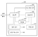
도 1의 실시예에 따르면, 보행 보조 장치(100)는 구동부(110), 센서부(120), 관성 (Inertial Measurement Unit; IMU) 센서(130) 및 제어부(140)를 포함한다.1, the
구동부(110)는 사용자의 고관절(hip joint)을 구동시킬 수 있다. 예를 들어, 구동부(110)는 사용자의 오른쪽 힙 및/또는 왼쪽 힙 부분에 위치할 수 있고, 회전 토크를 발생시킬 수 있는 모터를 포함할 수 있다.The
센서부(120)는 보행 시 사용자의 고관절의 각도를 측정할 수 있다. 센서부(120)에서 센싱되는 고관절의 각도에 대한 정보는 오른쪽 고관절의 각도, 왼쪽 고관절의 각도, 양쪽 고관절 각도들 간의 차이 및 고관절 운동 방향을 포함할 수 있다. 예를 들어, 센서부(120)는 구동부(110) 내에 위치할 수 있으며, 포텐셔미터를 포함할 수 있다. 포텐셔미터는 사용자의 보행 동작에 따른 R 축, L 축 관절 각도 및 R 축, L 축 관절 각속도를 센싱할 수 있다.The
관성 센서(130)는 보행 시 가속도 정보와 자세 정보를 측정할 수 있다. 예를 들어, 관성 센서(130)는 사용자의 보행 동작에 따른 x 축, y 축, z 축 가속도 및 x 축, y 축, z 축 각속도를 각각 센싱할 수 있다. 보행 보조 장치(100)는 관성 센서(130)에서 측정된 가속도 정보에 기반하여 사용자의 발이 착지하는 지점을 검출할 수 있다.The
보행 보조 장치(100)는 앞서 설명한 센서부(120) 및 관성 센서(130) 이외에, 보행 동작에 따른 사용자의 운동량 또는 생체 신호 등의 변화를 센싱할 수 있는 다른 센서(예를 들어, 근전도 센서(ElectroMyoGram sensor; EMG sensor))를 포함할 수 있다.In addition to the above-described
제어부(140)는 구동부(110)가 사용자의 보행을 돕기 위한 보조력을 출력하도록, 구동부(110)를 제어할 수 있다. 제어부(140)는 토크가 발생하도록 구동부(110)를 제어하는 제어 신호를 출력할 수 있으며, 제어부(140)가 출력한 제어 신호에 기반하여 구동부(110)는 토크를 발생시킬 수 있다. 토크는 외부에 의해 설정될 수도 있고, 제어부(140)에 의해 설정될 수도 있다.The
전술된 보행 보조 장치(100)는 사용자의 보행을 보조하는 기능 이외에, 사용자의 동작 상태를 판단하여 추가적인 기능을 제공할 수 있다. 예를 들어, 보행 보조 장치(100)는 사용자의 기립(standing)을 보조하는 기능을 제공할 수 있다. 아래 도 3 내지 도 16을 참조하여 보행 보조 장치(100)가 사용자의 기립을 보조하는 방법이 설명된다.The above-described
< 기립 보조 방법의 개요><Outline of standing assistance method>
도 3은 일 예에 따른 일어서는 동작을 도시한다.Figure 3 shows the standing up operation according to an example.
사람이 앉아 있는 상태에서 일어서기 위해서는 무게 중심을 발 끝쪽으로 이동시킨 후, 허리를 펴야한다. 허리 근육의 근력이 부족한 사람에게는 허리를 펴는 동작이 어려울 수 있고, 이런 경우, 팔 근육이 보조력으로 이용되기도 한다. 예를 들어, 사람은 일어설 때 손으로 무릎을 짚고, 팔을 펴면서 발생하는 지지력을 이용하여 허리를 펴기도 한다.To stand when a person is sitting, move the center of gravity to the end of the foot, then stretch your waist. For people who lack muscle strength in the back muscles, it may be difficult to stretch their backs, and in such cases, the arm muscle may be used as an auxiliary force. For example, a person may lift his / her waist with his / her knees when standing up and using the supporting force generated by extending his / her arms.
기립 보조를 위한 장치에 이러한 메커니즘이 적용될 수 있다. 예를 들어, 기립 보조를 위한 장치는 사용자의 무릎 부위에 압력이 가해지는 경우, 허리를 펴는 동작을 보조하는 보조력을 사용자에게 제공할 수 있다. 사용자는 무릎에 가하는 압력을 조절함으로써 출력되는 보조력을 조절할 수 있다. 아래 도 4 내지 도 16를 참조하여 기립을 보조하는 방법이 상세히 설명된다.This mechanism can be applied to devices for stand-by assistance. For example, the apparatus for standing up assistance may provide the user with an assist force to assist in the unfolding of the waist when pressure is applied to the knee area of the user. The user can adjust the auxiliary force outputted by adjusting the pressure applied to the knee. A method for assisting standing will be described in detail with reference to Figs. 4 to 16 below.
도 4는 일 실시예에 따른 기립 보조 장치의 구성도이다.FIG. 4 is a configuration diagram of a standing up assistance device according to an embodiment.
기립 보조 장치(400)는 전술된 보행 보조 장치(100)일 수 있으며, 사용자의 기립을 보조하는 기능 이외에 보행을 보조하는 보조력을 사용자에게 제공할 수 있다. 다른 예로, 기립 보조 장치(400)는 사용자의 기립을 보조하는 보조력만을 출력하는 단독(stand-alone) 장치로 사용될 수도 있다.The standing-up
기립 보조 장치(400)는 통신부(410), 프로세서(420), 구동 장치(430), 저장부(440), 압력 센서(450), 관절 각도 센서(460), 관성 측정 장치(Inertial measurement unit; IMU)(470)를 포함한다.The standing
통신부(410)는 프로세서(420), 저장부(440), 압력 센서(450), 관절 각도 센서(460) 및 IMU(470)와 연결되어 데이터를 송수신할 수 있다. 통신부(410)는 외부의 다른 장치와 연결되어 데이터를 송수신할 수 있다.The
프로세서(420)는 통신부(410)가 수신한 데이터 및 저장부(440)에 저장된 데이터를 처리할 수 있다. 프로세서(420)는 보조력에 관한 정보를 구동 장치(430)에 전송할 수 있다. 프로세서(420)는 전술된 도 1의 제어부(140)에 대응될 수 있다.The
구동 장치(430)는 보조력에 관한 정보에 기반하여 보조력을 출력할 수 있다. 구동 장치(430)는 전술된 도 1의 구동부(110)에 대응될 수 있다.The
저장부(440)는 통신부(410)가 수신한 데이터 및 프로세서(420)가 처리한 데이터를 저장할 수 있다.The
압력 센서(450)는 센서에 가해지는 압력을 측정할 수 있다. 압력 센서(450)는 기립 보조 장치(400)와 물리적으로 분리될 수 있다. 예를 들어, 압력 센서(450)는 무선 통신 방식(예를 들어, 블루투스(Bluetooth))을 이용하여 통신부(410)와 통신할 수 있다.The
관절 각도 센서(460)는 사용자의 관절의 각도를 측정할 수 있다.The
IMU(470)는 측정하고자 하는 물체의 방위 변화를 측정할 수 있다.The
도 5는 일 실시예에 따른 기립 보조 방법의 흐름도이다.5 is a flowchart of a standing assistance method in accordance with one embodiment.
단계(510)에서, 압력 센서(450)는 사용자의 신체 부위의 일부에 가해지는 압력을 측정할 수 있다. 압력 센서(450)는 사용자의 신체 부위, 예를 들어, 무릎, 대퇴(thigh) 또는 손바닥에 위치할 수 있다. 도 6을 참조하면, 압력 센서(630)는 기립 보조 장치의 무릎 부근에 장착되어 사용자가 손으로 무릎에 가하는 압력을 측정할 수 있다. 사용자의 신체 부위 이외의 위치에 압력 센서(450)가 장착되는 것도 가능하다. 예를 들어, 압력 센서(450)는 지팡이의 손잡이 부분에 위치하여 사용자가 손에 쥐고 압력을 가하면, 가해진 압력의 크기를 측정할 수도 있다. 압력 센서(450)는 압력이 가해지는 시간 동안의 변화를 측정할 수 있다.In
단계(520)에서, 프로세서(420)는 측정된 압력에 대응하는 토크에 관한 정보를 획득할 수 있다. 프로세서(420)는 미리 설정된 상수에 기반하여, 기립 보조를 위한 토크를 계산할 수 있다. 미리 설정된 상수는, 미리 정해진 캘리브레이션(calibration) 과정을 거쳐 사용자에 따라 다르게 설정될 수 있으며, 계산된 토크는 측정된 압력에 비례할 수 있다.At
단계(530)에서, 구동 장치(430)는 토크에 관한 정보에 기반하여 사용자의 신체에 보조력을 제공할 수 있다. 예를 들어, 구동 장치(430)는 모터를 이용하여 계산된 토크를 출력함으로써 보조력을 제공할 수 있다. 구동 장치(430)는 사용자의 고관절에 위치한 모터일 수 있고, 사용자의 허리 및 다리 사이를 벌리는 방향으로 보조력을 제공할 수 있다. 도 6을 참조하면, 구동 장치(650)는 기립 보조 장치의 허리 지지부(640) 및 허벅지 착용부(610)를 벌리는 방향으로 토크를 출력할 수 있다.At
도 7은 일 예에 따른 제공되는 보조력을 도시한다.FIG. 7 shows an assist force provided according to an example.
도 7의 제1 그래프(710)는 압력 센서가 측정한 압력을 힘으로 나타내고, 제2 그래프(720)는 구동 장치가 출력한 토크를 힘으로 나타낸다. 제3 그래프(730)는 다리에 작용하는 힘을 나타낸다.The
도 7의 y 축은 힘의 크기를 표시하고 있으며, 토크의 크기에 대응하는 힘의 크기로 이해될 수도 있다. 또한, y 축은 압력의 크기에 대응하는 힘의 크기로도 이해될 수 있다.The y-axis in Fig. 7 represents the magnitude of the force and may be understood as the magnitude of the force corresponding to the magnitude of the torque. The y-axis can also be understood as the magnitude of the force corresponding to the magnitude of the pressure.
토크는 아래의 [수학식 1]을 이용하여 계산될 수 있다.The torque can be calculated using the following equation (1).
![]()
![]()
[수학식 1]에서, FWadToLeg는 출력할 토크의 값이고, k는 미리 설정된 상수이고, FHandToLeg는 측정한 압력을 의미한다. [수학식 1]에 따르면, FWadToLeg는 FHandToLeg에 비례하지만, 계산된 값이 미리 설정된 값(Fwad _max)을 초과하는 경우에는 미리 설정된 값으로 계산될 수 있다.In Equation (1), F WadToLeg is the value of the torque to be output, k is a predetermined constant, and F HandToLeg indicates the measured pressure. According to Equation 1], F WadToLeg is may be calculated by a predetermined value if the proportion to HandToLeg F but exceeds the calculated value, a preset value (F wad _max).
다리에 작용하는 힘은 아래의 [수학식 2]를 이용하여 계산될 수 있다.The force acting on the leg can be calculated using the following equation (2).

사용자에게 최종적으로 제공되는 보조력(FLeg)은 사용자가 무릎에 가한 압력(FHandToLeg) 및 기립 보조 장치(400)가 제공한 토크(FWadToLeg)의 합일 수 있다.The auxiliary force F Leg ultimately provided to the user may be the sum of the pressure F HandToLeg applied by the user to the knee and the torque F WadToLeg provided by the standing
도 8은 일 예에 따른 기립 패턴을 생성하는 방법의 흐름도이다.8 is a flowchart of a method of generating an upright pattern according to an example.
도 5를 참조하여 전술된 기립 보조 방법은 아래의 단계들(810 및 820)을 더 포함할 수 있다. 기립 패턴은 기립 보조 장치(400)가 이전에 계산 또는 출력했던 기립 보조 토크에 기반하여 생성될 수 있다. 예를 들어, 사용자가 기립 보조 장치(400)를 통해 기립 보조 토크를 제공받은 횟수가 총 5회인 경우, 기립 보조 장치(400)는 계산 또는 출력된 5개의 기립 보조 토크를 분석하여 상기의 사용자의 기립 패턴을 생성할 수 있다. 기립 보조 장치(400)는 사용자가 선택하는 동작 모드에 따라, 사용자가 신체에 가하는 압력을 측정하지 않더라도 기립 패턴을 이용하여 기립 보조 토크를 출력할 수 있다.The standing-up assistant method described above with reference to Fig. 5 may further include the following
단계(810)에서, 프로세서(420)는 전술된 단계(520)에서 획득된 토크를 저장부(440)에 저장할 수 있다. 예를 들어, 프로세서(420)는 시간의 흐름에 따른 계산된 토크의 변화를 나타내는 토크 패턴을 저장할 수 있다. 프로세서(420)는 획득될 때마다 토크 패턴을 저장할 수도 있고, 일정한 횟수 까지만(예를 들어, 5회) 토크 패턴을 저장할 수도 있다.In
단계(820)에서, 프로세서(420)는 저장된 토크 패턴들에 기반하여 기립 패턴을 생성할 수 있다. 예를 들어, 프로세서(420)는 토크 패턴들과 오차가 가장 적도록 기립 패턴을 생성할 수 있다. 다른 예로, 프로세서(420)는 토크 패턴들에 기반하여 최대 토크, 토크의 증가 경사 및 토크의 감소 경사를 결정하고, 결정된 최대 토크, 토크의 증가 경사 및 토크의 감소 경사에 기반하여 기립 패턴을 생성할 수 있다.At
기립 패턴이 생성된 이후, 저장부(440)에 추가적인 토크 패턴들이 저장될 수 있다. 추가적인 토크 패턴들이 저장되는 경우, 프로세서(420)는 추가적인 토크 패턴들의 특성이 반영되도록 기립 패턴을 조정할 수 있다. 예를 들어, 프로세서(420)는 기존의 토크 패턴들 및 추가적인 토크 패턴들에 기반하여 기립 패턴을 다시 생성할 수 있다.After the standing pattern has been generated, additional torque patterns may be stored in the
단계들(810 및 820)는 전술된 단계(530)와 병렬적으로 수행될 수 있다.
기립 패턴은 압력이 측정되지 않는 경우에도 기립 보조 장치(400)의 동작 상태가 일어서는 상태로 판단된 경우 사용자에게 보조력을 제공하기 위해 이용될 수 있다. 동작 상태를 판단하는 방법에 대해서는, 도 11 내지 16을 참조하여 상세히 설명한다.The standing pattern may be used to provide an assist force to the user when it is determined that the standing state of the standing up
도 9는 일 예에 따른 생성된 기립 패턴을 도시한다.Figure 9 shows a generated standing pattern according to an example.
프로세서(420)는 토크 패턴들(901 내지 905)을 획득할 수 있다. 토크 패턴들(901 내지 905)은 압력이 측정되는 시간 동안 계산되는 토크의 변화를 나타낼 수 있다.The
프로세서(420)는 토크 패턴들(901 내지 905)을 대표할 수 있는 기립 패턴(910)을 생성할 수 있다. 예를 들어, 프로세서(420)는 패턴들의 지속 시간의 평균을 계산하고, 각 시각의 평균 토크를 계산할 수 있다. 프로세서(420)는 계산된 지속 시간의 평균 및 각 시각의 평균 토크에 기반하여 기립 패턴(910)을 생성할 수 있다. 다른 예로, 프로세서(420)는 토크 패턴들(901 내지 905)과 오차가 가장 적도록 기립 패턴(910)을 생성할 수 있다.The
도 10은 다른 일 예에 따른 생성된 기립 패턴을 도시한다.Figure 10 shows a generated standing pattern according to another example.
일 측면에 따르면, 프로세서(420)는 토크 패턴들(901 내지 905)에 기반하여 최대 토크, 최대 토크의 유지 기간, 토크의 증가 경사 및 토크의 감소 경사를 결정할 수 있다. 프로세서(420)는 결정된 최대 토크, 토크의 증가 경사 및 토크의 감소 경사에 기반하여 기립 패턴(1010)을 생성할 수 있다.According to one aspect, the
프로세서(420)는 토크 패턴들(901 내지 905)의 특성을 분석할 수 있다. 예를 들어, 프로세서(420)는 토크의 증가율, 최대 토크, 최대 토크의 유지 기간 및 토크의 감소율을 계산할 수 있다. 프로세서(420)는 토크의 증가율에 기반하여 토크의 증가 경사를 결정하고, 토크의 감소율에 기반하여 토크의 감소 경사를 결정할 수 있다. 프로세서(420)는 최대 토크, 최대 토크의 유지 기간, 토크의 증가 경사 및 토크의 감소 경사에 기반하여 기립 패턴(1010)을 생성할 수 있다.The
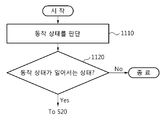
도 11은 일 예에 따른 동작 상태가 일어서는 상태인지 여부를 판단하는 방법의 흐름도이다.11 is a flowchart of a method for determining whether an operation state according to an example is in a standing state.
아래의 단계들(1110 내지 1120)은 전술된 단계(510)와 병렬적으로 수행될 수 있다.The following
단계(1110)에서, 프로세서(420)는 사용자 또는 기립 보조 장치(400)의 동작 상태를 판단할 수 있다. 기립 보조 장치(400)의 동작 상태는 사용자의 움직임이 반영된 것이기 때문에, 사용자의 동작 상태는 기립 보조 장치(400)의 동작 상태와 동일한 것으로 이해될 수 있다.At
일 측면에 따르면, 저장부(440)에는 복수의 동작 상태들이 저장되어 있을 수 있다. 프로세서(420)는 측정된 값들에 기반하여 현재의 동작이 복수의 동작 상태들 중 어떠한 동작 상태에 있는지 여부를 판단할 수 있다. 예를 들어, 프로세서(420)는 유한 상태 기계(Finite State Machine; FSM)를 이용하여 동작 상태를 판단할 수 있다. 사용자의 동작 상태를 판단하는 방법에 대해서는, 아래 도 12를 참조하여 상세히 설명한다.According to one aspect, the
단계(1120)에서, 프로세서(420)는 판단된 동작 상태가 일어서는 상태인지 여부를 판단할 수 있다. 동작 상태가 일어서는 상태인 경우, 전술된 단계(520)가 수행될 수 있다. 다시 말해, 일어서는 상태는 단계(520)가 수행되기 위한 조건일 수 있다. 예를 들어, 압력이 측정되는 경우에도, 동작 상태가 일어서는 상태가 아니라면 단계(520)가 수행되지 않을 수 있다.In
판단된 동작 상태가 일어서는 상태가 아닌 경우, 기립 보조 장치(400)는 동작을 종료할 수 있다. 기립 보조 장치(400)가 기립 보조 기능 이외에(예를 들어, 보행 보조 기능) 추가적인 기능을 가지고 있다면, 기립 보조 장치(400)는 판단된 동작 상태에 대응하는 보조력을 계산하고, 계산된 보조력을 출력할 수 있다. 예를 들어, 판단된 동작 상태가 보행 상태인 경우, 프로세서(420)는 보행 상태의 보행 싸이클(gait cycle)에 대응하는 보조력을 계산할 수 있다.If the determined operation state is not the state in which the determined operation state is not established, the standing assisting
일 측면에 따르면, 단계(510)가 수행되지 않은 경우에도 단계(1120)에서 사용자의 동작 상태가 일어서는 상태로 판단되고, 저장부(440)에 전술된 기립 패턴이 생성되어 있는 경우, 전술된 단계(520)가 수행될 수 있다. 이 경우, 단계(520)에서, 프로세서(420)는 기립 패턴을 이용하여 토크 정보를 획득할 수 있다.According to one aspect, even if the
도 12는 일 예에 따른 사용자의 동작 상태를 판단하는 방법의 흐름도이다.FIG. 12 is a flowchart of a method of determining an operation state of a user according to an example.
전술된 단계(1110)는 아래의 단계들(1210 내지 1240)을 포함할 수 있다.The
단계(1210)에서, 관절 각도 센서(460)는 사용자의 관절들에 대한 정보를 측정할 수 있다. 관절들에 대한 정보는 관절 각도, 관절 각도의 각속도 및 관절 각도의 각가속도를 포함할 수 있다. 관절 각도는 고관절, 무릎 관절 및 발목 관절을 포함할 수 있다. 관절 각도 센서(460)는 관절 각도를 측정하고, 측정된 관절 각도에 기반하여 관절 각속도 및 관절 각가속도를 계산할 수 있는 인코더(encoder)를 포함할 수 있다.In
단계(1220)에서, IMU(470)는 사용자의 상체 움직임을 센싱할 수 있다. 예를 들어, IMU(470)는 3 축에 대한 변화 각도를 센싱하고, 이에 기반하여 변화 각속도 및 변화 각가속도를 계산하여 사용자의 상체 움직임을 센싱할 수 있다.In
단계(1230)에서, 프로세서(420)는 관절 각도 및 상체 움직임에 기반하여 사용자의 다리의 회전 정보를 추정할 수 있다. 사용자의 동작 상태를 판단하기 위해 이용되는 다리의 회전 정보는 센서들을 통해 직접 센싱되는 것이 아니고, 관절들에 대한 정보에 기반하여 추정될 수 있다. 예를 들어, 다리의 회전 정보는 고관절 각도 및 상체의 각도에 기반하여 계산될 수 있다. 다리의 회전 정보는 회전 각도, 회전 각속도 및 회전 각가속도를 포함할 수 있다. 다리의 회전 정보는 사용자의 동작 상태를 판단하기 위한 오른쪽 및 왼쪽 다리의 앉은 각도를 더 포함할 수 있다. 다리의 회전 각도는 중력 방향을 기준으로 하는 다리의 각도일 수 있다. 다리의 회전 각도는 아래의 [수학식 3]을 이용하여 계산될 수 있다.At
![]()
![]()
A는 고관절 각도(도 13의 1320)이고, B는 상체의 각도(도 13의 1310)이고, C는 다리의 회전 각도이다.A is the hip joint angle (1320 in Fig. 13), B is the angle of the upper body (1310 in Fig. 13), and C is the rotation angle of the leg.
전술한 바와 같이 기립 보조 장치(400)가 사용자의 동작 상태를 판단하기 위한 데이터를 직접 센싱할 수 없는 경우, 센싱 가능한 데이터를 이용하여 사용자의 동작 상태를 판단하기 위한 데이터를 획득할 수 있다. 이를 통하여 기립 보조 장치(400)의 구성이 단순해 질 수 있고, 기립 보조 장치(400)의 타입에 관계 없이 사용자의 동작 상태를 판단할 수 있다.As described above, when the standing-up
단계(1240)에서, 프로세서(420)는 다리의 회전 정보에 기반하여 동작 상태를 판단할 수 있다. 프로세서(420)는 획득된 다리의 회전 정보를 미리 설정된 임계치와 비교함으로써, 동작 이벤트를 판단하기 위한 디지털화된(digitalized) 컨텍스트 정보로 맵핑할 수 있다. 동작 이벤트는 다리가 어떠한 움직임을 나타내는지를 의미할 수 있으며, 판단된 동작 이벤트에 기반하여 최종적으로 사용자의 동작 상태가 판단될 수 있다.In
다리의 회전 정보는 각각의 세부 정보에 대해 미리 설정된 임계치와 비교됨으로써, 아래의 [표 1]과 같이 각각의 세부 정보에 대응하는 디지털화된 컨텍스트 정보로 맵핑될 수 있다.The rotation information of the legs can be mapped to the digitized context information corresponding to each piece of detailed information as shown in [Table 1] below by being compared with preset thresholds for each piece of detailed information.
여기에서, LA는 왼쪽 다리의 회전 각도를 나타내고, RA는 오른쪽 다리의 회전 각도를 나타낸다. LSA는 왼쪽 다리의 앉은 각도를 나타내고, RSA는 오른쪽 다리의 앉은 각도를 나타내며, DA는 왼쪽 다리의 회전 각도 및 오른쪽 다리의 회전 각도 간의 차이를 나타낸다. LW는 왼쪽 다리의 회전 각속도를 나타내고, RW는 오른쪽 다리의 회전 각속도를 나타낸다.Here, LA represents the rotation angle of the left leg and RA represents the rotation angle of the right leg. LSA represents the sitting angle of the left leg, RSA represents the sitting angle of the right leg, and DA represents the difference between the rotational angle of the left leg and the rotational angle of the right leg. LW represents the rotational angular velocity of the left leg, and RW represents the rotational angular velocity of the right leg.
x는 임계치와 비교되는 변수를 나타낸다. 여기에서 lq는 왼쪽 다리의 회전 각도를 나타내고, rq는 오른쪽 다리의 회전 각도를 나타낸다. lq-rq는 왼쪽 다리의 회전 각도 및 오른쪽 다리의 회전 각도 간의 차이를 나타내고, lw는 왼쪽 다리의 회전 각속도를, rw는 오른쪽 다리의 회전 각속도를 나타낸다.x represents a variable to be compared with a threshold value. Here, lq represents the angle of rotation of the left leg, and rq represents the angle of rotation of the right leg. lq-rq represents the difference between the rotation angle of the left leg and the rotation angle of the right leg, lw represents the rotational angular velocity of the left leg, and rw represents the rotational angular velocity of the right leg.
일 측면에 따르면, LA와 LSA는 동일한 변수로 lq를 가지고, RA와 RSA는 동일한 변수로 rq를 가질 수 있다. LSA와 RSA는 직접 센싱되는 값이 아니고, 사용자의 동작 이벤트들 중 정지 상태를 나타내는 폄 이벤트와 굽힘 이벤트를 구분하기 위해 도입된 컨텍스트 정보일 수 있다.According to one aspect, LA and LSA have the same variable lq, and RA and RSA can have rq as the same variable. The LSA and RSA are not directly sensed values but may be context information introduced to distinguish a bending event from a braking event indicating a stop state among user's operation events.
LSA가 LA와 동일한 변수를 이용하고, RSA가 RA와 동일한 변수를 이용하고, 설정된 임계치만을 다르게 함으로써, LSA와 RSA를 동작 이벤트 구분을 위해 이용되는 컨텍스트 정보로 활용할 수 있다.The LSA and the RSA can be utilized as the context information used for distinguishing the operation event by using the same variable as the LA, using the same variable as the RA, and different only the set threshold value.
e는 오른쪽 다리의 회전 각도 및 왼쪽 다리의 회전 각도에 대해 미리 설정된 임계치일 수 있다. 임계치 e는 사용자가 움직임을 의도하지 않은 경우에도, 작은 움직임으로 인해 데이터가 센싱되는 경우 상기의 의도하지 않은 작은 움직임을 필터링하기 위해 이용될 수 있다. 다만, 상술한 [표 1]의 임계치 e는 설명의 목적을 위한 일 예일 뿐이며 이에 제한되는 것은 아니며, 사용자의 특성에 적합하게 다르게 설정될 수도 있다.e may be a preset threshold value for the rotation angle of the right leg and the rotation angle of the left leg. The threshold value e may be used to filter the unintended small motion when data is sensed due to small motion, even if the user does not intend to move. However, the threshold value e in the above-mentioned [Table 1] is only an example for the purpose of explanation, but it is not limited thereto and may be set differently according to the characteristics of the user.
프로세서(420)는 다리의 회전 정보의 세부 정보를 미리 설정된 임계치와 각각 비교하여 컨텍스트 정보로 맵핑할 수 있다. 예를 들어, 왼쪽 다리의 회전 각도(LA)의 경우, 왼쪽 다리의 회전 각도(LA)에 대응하는 변수 값인 lq가 미리 설정된 임계치인 5° 보다 큰 경우 컨텍스트 정보가 1로 맵핑될 수 있다. 변수 값 lq가 임계치의 음수 값인 -5° 보다 작은 경우, 컨텍스트 정보가 -1로 맵핑될 수 있다. 변수 값 lq가 임계치의 음수 값인 -5° 이상이고, 임계치인 5° 이하인 경우 컨텍스트 정보가 0으로 맵핑될 수 있다.The
프로세서(420)는 오른쪽 다리의 회전 정보 및 왼쪽 다리의 회전 정보 각각에 대해 미리 설정된 임계치와 비교함으로써, 컨텍스트 정보로 맵핑할 수 있다. 맵핑된 컨텍스트 정보는 동작 이벤트를 판단하기 위해 이용될 수 있다. 동작 이벤트는 사용자의 동작 상태를 판단하기 위해 센싱된 정보들에 기반하여 추정되는 사용자의 다리의 움직임의 변화일 수 있다. 다시 말하자면, 동작 이벤트 자체가 사용자의 최종 동작 상태로 인식되는 것은 아니며, 동작 이벤트 및 사용자의 이전 동작 상태가 고려되어 사용자의 현재 동작 상태가 판단될 수 있다. 예를 들어, 사용자의 이전 동작 상태가 서 있는 상태에서 동작 이벤트로 스윙 이벤트가 발생하는 경우, 사용자의 현재 동작 상태는 보행 상태로 판단될 수 있다. 다른 예로, 사용자의 이전 동작 상태가 앉아 있는 상태에서 동작 이벤트로 스윙 이벤트가 발생하는 경우에도, 사용자의 현재 동작 상태는 앉아 있는 상태로 판단될 수 있다.The
사용자의 동작 상태는 연속적으로 이루어 지는 것이므로 동일한 동작 이벤트들이 각각 발생하더라도 사용자의 이전 동작 상태에 따라 사용자의 현재 동작 상태는 다르게 판단될 수 있다. 동작 이벤트는 현재 사용자의 동작 상태를 판단하기 위해 이용되는 사용자의 다리의 회전 정보일 수 있다.Since the operation state of the user is continuously performed, the current operation state of the user can be determined differently according to the previous operation state of the user even if the same operation events occur. The operation event may be rotation information of the user's leg used to determine the current operation state of the user.
프로세서(420)는 미리 설정된 기준에 따라 맵핑된 컨텍스트 정보에 대응하는 동작 이벤트를 생성할 수 있다. 프로세서(420)는 맵핑된 컨텍스트 정보의 조합이 미리 설정된 기준에 따라 특정 동작 이벤트에 대응하는지를 결정할 수 있고, 결정된 동작 이벤트를 생성할 수 있다.
일 측면에 따르면, 프로세서(420)는 대응된 동작 이벤트의 지속 시간을 확인할 수 있다. 지속 시간이 미리 설정된 시간 이상인 경우, 상기의 결정된 동작 이벤트를 최종적으로 생성할 수 있다.According to one aspect, the
프로세서(420)가 결정된 동작 이벤트의 지속 시간을 확인함으로써, 센싱되는 데이터의 노이즈 또는 사용자의 의도하지 않은 움직임을 필터링할 수 있다. 동작 이벤트의 지속 시간을 확인함으로써 필요 이상으로 잦은 움직임이 감지되는 것을 피할 수 있고, 이를 통해 신뢰성 있는 결과를 얻을 수 있다.
프로세서(420)는 생성된 동작 이벤트 및 사용자의 이전 동작 상태에 기반하여 현재 사용자의 동작 상태를 판단할 수 있다. 동일한 동작 이벤트들이 발생하더라도 사용자의 이전 동작 상태에 따라 현재 사용자의 동작 상태는 다르게 판단될 수 있으므로 사용자의 이전 동작이 고려될 수 있다.The
사용자의 동작 상태는 서 있는 상태(stand), 앉는 상태(stand to sit), 앉아 있는 동작(sit) 및 일어서는 동작(sit to stand)을 포함할 수 있다. 추가적으로, 동작 상태는 보행 동작(walk)을 더 포함할 수 있다.The user's operational state may include a standing state, a stand-by state, a sitting state, and a sit-to-stand state. Additionally, the operating state may further include a walking operation (walk).
프로세서(420)는 사용자의 동작 상태를 판단하기 위해 사용자의 동작 상태들 간의 관계를 설정하는 FSM을 이용할 수 있다. 동작 상태를 판단하는 방법은 아래에서 도 16을 참조하여 상세히 설명된다.The
도 13은 일 예에 따른 사용자의 관절 각도를 도시한다.13 shows the joint angle of the user according to an example.
관절 각도는 고관절의 각도(1320), 무릎 관절의 각도(1330) 및 발목 관절의 각도(1340)를 포함할 수 있다. 예를 들어, 고관절의 각도(1320)는 허리 지지부 및 허벅지 연결부가 형성하는 각도일 수 있으며, 무릎 관절의 각도(1330) 및 발목 관절 각도(1340)는 각각 허벅지 연결부 및 종아리 지지부가 형성하는 각도, 그리고 종아리 연결부 및 발바닥이 형성하는 각도일 수 있다. 관절 각도 센서(460)는 왼쪽 및 오른쪽의 고관절 각도, 무릎 관절 각도 및 발목 관절 각도를 측정할 수 있다.The joint angle may include an
중력 방향 및 허리 지지부 간의 상체 각도(1310)는 IMU(470)를 통해 측정되고, 상체 각도(1310) 및 고관절의 각도(1320)에 기반하여 다리의 회전 정보가 계산될 수 있다.The
일 측면에 따르면, 관절 각도는 미리 정해진 시간 간격으로 반복적으로 측정되어 사용자의 동작 상태를 반복적으로 갱신하는데 이용될 수 있다.According to one aspect, the joint angle may be repeatedly measured at predetermined time intervals and used to repeatedly update the user's operating state.
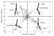
도 14는 일 예에 따른 동작 이벤트를 사용자의 오른쪽 다리의 회전 각속도 및 왼쪽 다리의 회전 각속도에 따라 구분한 그래프이다.FIG. 14 is a graph in which an operation event according to an example is divided according to a rotational angular velocity of a user's right leg and a rotational angular velocity of a left leg.
도 14의 그래프에서, x 축은 왼쪽 다리의 회전 각속도를 나타내고, y 축은 오른쪽 다리의 회전 각속도를 나타낸다. 사용자의 각 동작 이벤트가 상기의 그래프의 각 사분면에 대응될 수 있다.In the graph of Fig. 14, the x-axis represents the rotational angular velocity of the left leg and the y-axis represents the rotational angular velocity of the right leg. Each action event of the user can correspond to each quadrant of the graph.
예를 들어, 그래프의 2 사분면 및 4 사분면은 사용자의 오른쪽 다리의 회전 각속도 및 왼쪽 다리의 회전 각속도의 부호가 서로 반대이다. 오른쪽 다리의 회전 각속도 및 왼쪽 다리의 회전 각속도의 부호가 서로 반대인 것은 사용자의 오른쪽 다리와 왼쪽 다리가 서로 다른 방향으로 움직이고 있음을 나타낸다. 그래프의 2 사분면 및 4 사분면 영역은 스윙 이벤트에 대응될 수 있다.For example, the quadrants and quadrants of the graph are opposite in sign of the rotational angular velocity of the user's right leg and the rotational angular velocity of the left leg. The signs of the rotational angular velocity of the right leg and the rotational angular velocity of the left leg are opposite to each other, indicating that the user's right leg and left leg are moving in different directions. The second and fourth quadrant regions of the graph can correspond to swing events.
그래프의 1 사분면 및 3 사분면은 사용자의 오른쪽 다리의 회전 각속도 및 왼쪽 다리의 회전 각속도의 부호가 서로 동일하다. 오른쪽 다리의 회전 각속도 및 왼쪽 다리의 회전 각속도의 부호가 서로 동일한 것은 사용자의 오른쪽 다리와 왼쪽 다리가 서로 같은 방향으로 움직이고 있음을 나타낸다.In the first and third quadrants of the graph, the sign of the rotational angular velocity of the user's right leg and the rotational angular velocity of the left leg are the same. The signs of the rotational angular velocity of the right leg and the rotational angular velocity of the left leg are the same, indicating that the user's right leg and left leg are moving in the same direction.
보다 구체적으로, 그래프의 1 사분면은 오른쪽 다리의 회전 각속도와 왼쪽 다리의 회전 각속도가 모두 양의 값을 가진다. 오른쪽 다리의 회전 각속도와 왼쪽 다리의 회전 각속도가 모두 양의 값을 가지는 것은 오른쪽 다리 및 왼쪽 다리가 모두 굽혀지는 방향으로 움직이고 있음을 나타낸다. 양쪽 다리가 모두 굽혀지는 방향으로 움직이는 경우, 사용자의 동작 상태는 앉는 동작, 즉 하강하는 동작일 수 있다. 예를 들어, 그래프의 1 사분면의 영역은 하강 이벤트에 대응될 수 있다.More specifically, the first quadrant of the graph has a positive angular velocity of rotation of the right leg and a rotational angular velocity of the left leg. A positive value of both the rotational angular velocity of the right leg and the rotational angular velocity of the left leg indicates that both the right leg and the left leg are moving in a bending direction. When both legs move in the direction in which they are bent, the user's operating condition may be a sitting, or descending, action. For example, the area of the first quadrant of the graph may correspond to a falling event.
1 사분면과는 반대로, 그래프의 3 사분면에서는 오른쪽 다리의 회전 각속도와 왼쪽 다리의 회전 각속도가 모두 음의 값을 가진다. 오른쪽 다리의 회전 각속도와 왼쪽 다리의 회전 각속도가 모두 음의 값을 가지는 것은 오른쪽 다리 및 왼쪽 다리가 모두 펴지는 방향으로 움직이고 있음을 나타낸다. 양쪽 다리가 모두 펴지는 방향으로 움직이는 경우, 사용자의 동작 상태는 일어서는 동작, 즉 상승하는 동작일 수 있다. 예를 들어, 그래프의 3 사분면 영역은 상승 이벤트에 대응될 수 있다.Contrary to the first quadrant, in the third quadrant of the graph, both the rotational angular velocity of the right leg and the rotational angular velocity of the left leg are negative. When the angular velocity of rotation of the right leg and the angular velocity of rotation of the left leg are both negative, it indicates that both the right leg and the left leg are moving in the direction of expansion. When both legs move in the direction of spreading, the user's operating state may be an up, or rising, action. For example, the third quadrant area of the graph may correspond to a rising event.
상기의 일 예와 같이 각 동작 이벤트는 사용자의 오른쪽 다리의 회전 각속도 및 왼쪽 다리의 회전 각속도의 특성에 따라 구분될 수 있다.As shown in the above example, each operation event can be classified according to the characteristics of the rotational angular velocity of the right leg of the user and the rotational angular velocity of the left leg.
그래프의 중앙에 표시된 곡선은 각 동작 이벤트에 따른 사용자의 오른쪽 다리의 회전 각속도의 데이터 및 왼쪽 다리의 회전 각속도의 데이터를 상기의 그래프 x 축 및 y 축에 따라 오른쪽 다리의 회전 각속도 및 왼쪽 다리의 회전 각속도의 관계로 나타낸 것이다. 상기의 곡선을 통해 실제 사용자의 동작 이벤트에 따라 계산되는 사용자의 오른쪽 다리의 회전 각속도 및 왼쪽 다리의 회전 각속도의 관계도 서로 동일한 특성을 반영하고 있음을 알 수 있다.The curve shown at the center of the graph shows the data of the rotational angular velocity of the user's right leg according to each motion event and the data of the rotational angular velocity of the left leg to the rotational angular velocity of the right leg and the rotational angular velocity of the left leg Angular velocity. It can be seen that the relationship between the rotational angular velocity of the user's right leg and the rotational angular velocity of the left leg calculated according to the actual user's motion event reflects the same characteristics through the curve.
아래의 도 15를 참조하여 동작 이벤트에 따른 사용자의 오른쪽 다리의 회전 각도 및 왼쪽 다리의 회전 각도의 특성에 따라 동작 이벤트를 구분하고, 구분된 동작 이벤트를 생성하는 방법에 대해 설명된다.A method of distinguishing an operation event according to a rotation angle of a user's right leg and a rotation angle of a left leg according to an operation event and generating a divided operation event will be described with reference to FIG.
도 15는 일 예에 따른 동작 이벤트를 단순화한 모델을 도시한다.FIG. 15 illustrates a model that simplifies an operation event according to an example.
일 측면에 따르면, 동작 이벤트는 스윙(swing) 이벤트(1510), 폄(extension) 이벤트(1520), 하강(descending) 이벤트(1530), 굽힘(flexion) 이벤트(1540) 및 상승(ascending) 이벤트(1550)를 포함할 수 있다.According to one aspect, an action event includes a
상기의 도 14를 참조하여 전술된 스윙 이벤트, 상승 이벤트 및 하강 이벤트 외에, 동작 이벤트는 사용자의 정지 상태 이벤트인 폄 이벤트 및 굽힘 이벤트를 더 포함할 수 있다In addition to the above-described swing event, rising event, and falling event described above with reference to FIG. 14, the operation event may further include a user's pause event and a bending event
아래의 [표 2]는 각 동작 이벤트에 따른 오른쪽 다리의 회전 각도 및 왼쪽 다리의 회전 각도의 특성을 나타낸다.Table 2 below shows the characteristics of the rotation angle of the right leg and the rotation angle of the left leg according to each operation event.
스윙 이벤트(1510)는 보행 시와 같이 다리를 교차하여 움직이는 이벤트일 수 있다. 스윙 이벤트(1510)는 오른쪽 다리의 회전 각속도(rw)와 왼쪽 다리의 회전 각속도(lw)가 서로 반대 방향인 경우일 수 있다. 오른쪽 다리의 회전 각속도와 왼쪽 다리의 회전 각속도의 부호가 반대인 경우, 동작 이벤트는 스윙 이벤트(1510)로 결정될 수 있다.The
폄 이벤트(1520)는 오른쪽 다리의 회전 각속도(rw) 및 왼쪽 다리의 각속도(lw)가 0에 가까울 수 있다. 폄 이벤트(1520)는 오른쪽 다리의 회전 각도(rq) 및 왼쪽 다리의 각도(lq)가 모두 특정 각도(θs) 이하로 펴져 있으며, 오른쪽 다리의 회전 각도(rq) 및 왼쪽 다리의 각도(lq) 간의 차이(lq-rq)가 0에 가까운 경우이다.The
하강 이벤트(1530)는 오른쪽 다리의 회전 각속도(rw) 및 왼쪽 다리의 회전 각속도(lw)가 양(+)이고, 오른쪽 다리의 회전 각도(rq) 및 왼쪽 다리의 회전 각도(lq) 간의 각도 차이(lq-rq)가 거의 0에 가까운 경우이다.The
굽힘 이벤트(1540)는 오른쪽 다리의 회전 각속도(rw) 및 왼쪽 다리의 회전 각속도(lw)가 0에 가깝고, 오른쪽 다리의 회전 각도(rq) 및 왼쪽 다리의 회전 각도(lq)가 모두 특정 각도(θs) 이상으로 굽혀져 있으며, 오른쪽 다리의 회전 각도(rq) 및 왼쪽 다리의 회전 각도(lq) 간의 차이(lq-rq)가 0에 가까운 경우이다.The
상승 이벤트(1550)는 오른쪽 다리의 회전 각속도(rw) 및 왼쪽 다리의 회전 각속도(lw)가 음(-)이고, 오른쪽 다리의 회전 각도(rq) 및 왼쪽 다리의 회전 각도(lq) 간의 차이(lq-rq)가 0에 가까운 경우이다.The rising
일 측면에 따르면, 각 동작 이벤트는 각 동작 이벤트마다 설정된 지속 시간 이상 각 동작 이벤트에 따른 조건이 유지되어야 생성될 수 있다. 지속 시간을 통해 측정 노이즈나 사용자의 작은 움직임과 같이 확실하지 않은 움직임을 필터링할 수 있다. 지속 시간을 설정하는 경우 필요이상으로 잦은 동작 상태의 변화 감지를 피할 수 있어 신뢰성 있는 결과가 얻어질 수 있다.According to an aspect, each operation event can be generated only when a condition according to each operation event is maintained over a predetermined duration for each operation event. The duration can filter out uncertain movements such as measurement noise or small movements of the user. When the duration is set, it is possible to avoid detection of frequent changes in the operation state more than necessary, and a reliable result can be obtained.
프로세서(420)는 대응된 동작 이벤트의 지속 시간을 확인할 수 있다. 지속 시간이 미리 설정된 시간 이상인 경우, 대응된 동작 이벤트를 최종적으로 생성할 수 있다.The
전술된 바와 같이 각 동작 이벤트는 다리의 회전 정보에 따라 구분될 수 있다. 예를 들어, 동작 이벤트가 아래의 [표 3]과 같이 맵핑된 컨텍스트 정보의 조합을 통해 구분될 수 있다.As described above, each operation event can be classified according to the rotation information of the legs. For example, an action event can be distinguished through a combination of context information mapped as shown in [Table 3] below.
[표 3]은 각 동작 이벤트에 따른 오른쪽 다리의 회전 정보 및 왼쪽 다리의 회전 정보의 특성에 기반하여 컨텍스트 정보가 각 동작 이벤트에 대응하는 조건을 나타낸다.Table 3 shows the conditions in which the context information corresponds to each operation event based on the characteristics of the rotation information of the right leg and the rotation information of the left leg according to each operation event.
프로세서(420)는 [표 3]과 같은 미리 설정된 조건에 따라 맵핑된 컨텍스트 정보에 대응하는 동작 이벤트를 생성할 수 있다. 생성된 동작 이벤트는 사용자의 현재 동작 상태를 판단하기 위해 이용될 수 있다.The
도 16은 일 예에 따른 복수의 동작 상태들에 대한 천이를 도시한다.16 illustrates a transition for a plurality of operating states according to an example.
프로세서(420)는 생성된 동작 이벤트 및 사용자의 이전 동작 상태에 기반하여 사용자의 동작 상태를 판단할 수 있다.The
일 측면에 따르면, 프로세서(420)는 미리 설정된 복수의 동작 상태들 중 추정된 회전 정보에 대응하는 동작 상태를 판단할 수 있다. 예를 들어, 프로세서(420)는 추정된 회전 정보에 기반하여 생성된 동작 이벤트에 기반하여 동작 상태를 판단할 수 있다.According to an aspect, the
동일한 동작 이벤트가 발생한 경우에도, 사용자의 이전 동작 상태에 따라 현재 사용자의 동작 상태는 다르게 인식될 수 있으므로 사용자의 이전 동작이 고려될 수 있다.Even if the same operation event occurs, the previous operation of the user can be considered because the current operation state of the current user can be recognized differently according to the previous operation state of the user.
사용자의 동작 상태는 서 있는 동작(stand), 앉아 있는 동작(sit), 일어서는 동작(sit to stand) 및 앉는 동작(stand to sit)을 포함할 수 있다. 추가적으로 동작 상태는 보행 동작(walk)을 더 포함할 수 있으나, 도 16에는 도시되지 않았다.The user's operating state may include a standing stand, a sitting position, a sit to stand and a stand to sit. In addition, the operational state may further include a walk operation (walk), but is not shown in Fig.
프로세서(420)는 사용자의 동작 상태들을 구분하기 위해 사용자의 동작 상태들 간의 관계에 따라 설정되는 FSM을 이용할 수 있다.The
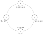
FSM은 상술한 사용자의 동작 상태에 따라 구분되는 복수의 동작 상태들을 포함할 수 있다. 예를 들어, 복수의 동작 상태들은 앉아 있는 상태(S0), 일어서는 상태(S1), 서 있는 상태(S2) 및 않는 상태(S3)를 포함할 수 있다.The FSM may include a plurality of operating states that are classified according to the operating state of the user. For example, the plurality of operating states may include a sitting state S0, a standing state S1, a standing state S2, and a non-standing state S3.
동작 이벤트가 복수의 동작 상태들 간의 천이(transition) 조건으로 설정될 수 있다. 전술한 바와 같이 사용자의 동작 상태는 연속적으로 이루어 지는 것이고, 동작 상태들 간의 천이는 동작 상태에 따른 특정 동작 이벤트의 생성에 따라 발생될 수 있다.An operation event can be set as a transition condition between a plurality of operation states. As described above, the user's operation state is continuous, and the transition between the operation states can be generated according to the generation of the specific operation event according to the operation state.
예를 들어, 사용자의 이전 동작 상태가 일어서는 상태(S1)인 경우, 동작 이벤트로 폄 이벤트가 생성되는 경우, 현재 사용자의 동작 상태는 서 있는 상태(S2)으로 판단될 수 있다.For example, when the previous operation state of the user is a state (S1), if an operation event is generated as an operation event, the operation state of the current user may be determined as the standing state (S2).
다른 예로, 사용자의 이전 동작 상태가 서 있는 상태(S2)인 경우, 동작 이벤트로 하강 이벤트가 생성되는 경우, 현재 사용자의 동작 상태는 앉는 상태(S3)로 판단될 수 있다.As another example, when the previous operation state of the user is the standing state (S2), when the falling event is generated as the operation event, the operation state of the current user may be determined as the sitting state (S3).
또 다른 예로, 사용자의 이전 동작 상태가 앉는 상태(S3)인 경우, 동작 이벤트로 굽힘 이벤트가 생성되는 경우, 현재 사용자의 동작 상태는 앉아 있는 상태(S0)로 판단될 수 있다.As another example, when the previous operation state of the user is the sitting state S3, when the bending event is generated as the operation event, the operation state of the current user may be determined as the sitting state S0.
또 다른 예로, 사용자의 이전 동작이 앉아 있는 상태(S0)인 경우, 동작 이벤트로 상승 이벤트가 생성하는 경우, 현재 사용자의 동작 상태는 일어 서는 상태(S1)로 판단될 수 있다.As another example, when the previous operation of the user is the sitting state S0, if the rising event is generated as the operation event, the operation state of the current user can be determined as the standing state S1.
프로세서(420)는 생성된 동작 이벤트 및 이전 사용자의 동작 상태에 기반하여 현재 사용자의 동작 상태를 판단할 수 있다.The
상술한 FSM에 대한 설명은 일 예를 설명하기 위한 목적일 뿐 이에 제한되는 것은 아니다. 사용자의 동작 상태들 간의 관계를 고려하여 각 동작 상태 및 천이 조건이 다르게 설정될 수 있음은 해당 기술 분야의 통상의 기술자에게 있어 명백하다.The description of the FSM described above is intended to illustrate an example, but is not limited thereto. It is obvious to those skilled in the art that the respective operating states and transition conditions can be set differently in view of the relationship between the operating states of the user.
실시예에 따른 방법은 다양한 컴퓨터 수단을 통하여 수행될 수 있는 프로그램 명령 형태로 구현되어 컴퓨터 판독 가능 매체에 기록될 수 있다. 상기 컴퓨터 판독 가능 매체는 프로그램 명령, 데이터 파일, 데이터 구조 등을 단독으로 또는 조합하여 포함할 수 있다. 상기 매체에 기록되는 프로그램 명령은 실시예를 위하여 특별히 설계되고 구성된 것들이거나 컴퓨터 소프트웨어 당업자에게 공지되어 사용 가능한 것일 수도 있다. 컴퓨터 판독 가능 기록 매체의 예에는 하드 디스크, 플로피 디스크 및 자기 테이프와 같은 자기 매체(magnetic media), CD-ROM, DVD와 같은 광기록 매체(optical media), 플롭티컬 디스크(floptical disk)와 같은 자기-광 매체(magneto-optical media), 및 롬(ROM), 램(RAM), 플래시 메모리 등과 같은 프로그램 명령을 저장하고 수행하도록 특별히 구성된 하드웨어 장치가 포함된다. 프로그램 명령의 예에는 컴파일러에 의해 만들어지는 것과 같은 기계어 코드뿐만 아니라 인터프리터 등을 사용해서 컴퓨터에 의해서 실행될 수 있는 고급 언어 코드를 포함한다. 상기된 하드웨어 장치는 실시예의 동작을 수행하기 위해 하나 이상의 소프트웨어 모듈로서 작동하도록 구성될 수 있으며, 그 역도 마찬가지이다.The method according to an embodiment may be implemented in the form of a program command that can be executed through various computer means and recorded in a computer-readable medium. The computer-readable medium may include program instructions, data files, data structures, and the like, alone or in combination. The program instructions to be recorded on the medium may be those specially designed and configured for the embodiments or may be available to those skilled in the art of computer software. Examples of computer-readable media include magnetic media such as hard disks, floppy disks and magnetic tape; optical media such as CD-ROMs and DVDs; magnetic media such as floppy disks; Magneto-optical media, and hardware devices specifically configured to store and execute program instructions such as ROM, RAM, flash memory, and the like. Examples of program instructions include machine language code such as those produced by a compiler, as well as high-level language code that can be executed by a computer using an interpreter or the like. The hardware devices described above may be configured to operate as one or more software modules to perform the operations of the embodiments, and vice versa.
이상과 같이 실시예들이 비록 한정된 도면에 의해 설명되었으나, 해당 기술분야에서 통상의 지식을 가진 자라면 상기의 기재로부터 다양한 수정 및 변형이 가능하다. 예를 들어, 설명된 기술들이 설명된 방법과 다른 순서로 수행되거나, 및/또는 설명된 시스템, 구조, 장치, 회로 등의 구성요소들이 설명된 방법과 다른 형태로 결합 또는 조합되거나, 다른 구성요소 또는 균등물에 의하여 대치되거나 치환되더라도 적절한 결과가 달성될 수 있다.While the present invention has been particularly shown and described with reference to exemplary embodiments thereof, it is to be understood that the invention is not limited to the disclosed exemplary embodiments. For example, it is to be understood that the techniques described may be performed in a different order than the described methods, and / or that components of the described systems, structures, devices, circuits, Lt; / RTI > or equivalents, even if it is replaced or replaced.
그러므로, 다른 구현들, 다른 실시예들 및 특허청구범위와 균등한 것들도 후술하는 특허청구범위의 범위에 속한다.Therefore, other implementations, other embodiments, and equivalents to the claims are also within the scope of the following claims.
소프트웨어는 컴퓨터 프로그램(computer program), 코드(code), 명령(instruction), 또는 이들 중 하나 이상의 조합을 포함할 수 있으며, 원하는 대로 동작하도록 처리 장치를 구성하거나 독립적으로 또는 결합적으로(collectively) 처리 장치를 명령할 수 있다. 소프트웨어 및/또는 데이터는, 처리 장치에 의하여 해석되거나 처리 장치에 명령 또는 데이터를 제공하기 위하여, 어떤 유형의 기계, 구성요소(component), 물리적 장치, 가상 장치(virtual equipment), 컴퓨터 저장 매체 또는 장치, 또는 전송되는 신호 파(signal wave)에 영구적으로, 또는 일시적으로 구체화(embody)될 수 있다. 소프트웨어는 네트워크로 연결된 컴퓨터 시스템 상에 분산되어서, 분산된 방법으로 저장되거나 실행될 수도 있다. 소프트웨어 및 데이터는 하나 이상의 컴퓨터 판독 가능 기록 매체에 저장될 수 있다.The software may include a computer program, code, instructions, or a combination of one or more of the foregoing, and may be configured to configure the processing device to operate as desired or to process it collectively or collectively Device can be commanded. The software and / or data may be in the form of any type of machine, component, physical device, virtual equipment, computer storage media, or device , Or may be permanently or temporarily embodied in a transmitted signal wave. The software may be distributed over a networked computer system and stored or executed in a distributed manner. The software and data may be stored on one or more computer readable recording media.
실시예에 따른 방법은 다양한 컴퓨터 수단을 통하여 수행될 수 있는 프로그램 명령 형태로 구현되어 컴퓨터 판독 가능 매체에 기록될 수 있다. 상기 컴퓨터 판독 가능 매체는 프로그램 명령, 데이터 파일, 데이터 구조 등을 단독으로 또는 조합하여 포함할 수 있다. 상기 매체에 기록되는 프로그램 명령은 실시예를 위하여 특별히 설계되고 구성된 것들이거나 컴퓨터 소프트웨어 당업자에게 공지되어 사용 가능한 것일 수도 있다. 컴퓨터 판독 가능 기록 매체의 예에는 하드 디스크, 플로피 디스크 및 자기 테이프와 같은 자기 매체(magnetic media), CD-ROM, DVD와 같은 광기록 매체(optical media), 플롭티컬 디스크(floptical disk)와 같은 자기-광 매체(magneto-optical media), 및 롬(ROM), 램(RAM), 플래시 메모리 등과 같은 프로그램 명령을 저장하고 수행하도록 특별히 구성된 하드웨어 장치가 포함된다. 프로그램 명령의 예에는 컴파일러에 의해 만들어지는 것과 같은 기계어 코드뿐만 아니라 인터프리터 등을 사용해서 컴퓨터에 의해서 실행될 수 있는 고급 언어 코드를 포함한다. 상기된 하드웨어 장치는 실시예의 동작을 수행하기 위해 하나 이상의 소프트웨어 모듈로서 작동하도록 구성될 수 있으며, 그 역도 마찬가지이다.The method according to an embodiment may be implemented in the form of a program command that can be executed through various computer means and recorded in a computer-readable medium. The computer-readable medium may include program instructions, data files, data structures, and the like, alone or in combination. The program instructions to be recorded on the medium may be those specially designed and configured for the embodiments or may be available to those skilled in the art of computer software. Examples of computer-readable media include magnetic media such as hard disks, floppy disks and magnetic tape; optical media such as CD-ROMs and DVDs; magnetic media such as floppy disks; Magneto-optical media, and hardware devices specifically configured to store and execute program instructions such as ROM, RAM, flash memory, and the like. Examples of program instructions include machine language code such as those produced by a compiler, as well as high-level language code that can be executed by a computer using an interpreter or the like. The hardware devices described above may be configured to operate as one or more software modules to perform the operations of the embodiments, and vice versa.
이상과 같이 실시예들이 비록 한정된 도면에 의해 설명되었으나, 해당 기술분야에서 통상의 지식을 가진 자라면 상기의 기재로부터 다양한 수정 및 변형이 가능하다. 예를 들어, 설명된 기술들이 설명된 방법과 다른 순서로 수행되거나, 및/또는 설명된 시스템, 구조, 장치, 회로 등의 구성요소들이 설명된 방법과 다른 형태로 결합 또는 조합되거나, 다른 구성요소 또는 균등물에 의하여 대치되거나 치환되더라도 적절한 결과가 달성될 수 있다.While the present invention has been particularly shown and described with reference to exemplary embodiments thereof, it is to be understood that the invention is not limited to the disclosed exemplary embodiments. For example, it is to be understood that the techniques described may be performed in a different order than the described methods, and / or that components of the described systems, structures, devices, circuits, Lt; / RTI > or equivalents, even if it is replaced or replaced.
400: 기립 보조 장치
410: 통신부
420: 프로세서
430: 구동 장치
440: 저장부
450: 압력 센서
460: 관절 각도 센서
470: 관성 측정 장치400: Standing auxiliary device
410:
420: processor
430: Driving device
440:
450: Pressure sensor
460: joint angle sensor
470: inertia measuring device
Claims (24)
상기 측정된 압력에 대응하는 토크에 관한 정보를 획득하는 단계; 및
상기 토크에 관한 정보에 기반하여 상기 사용자의 신체에 기립 보조력을 제공하는 단계
를 포함하는,
기립 보조 방법.
Measuring pressure applied to the body part of the user;
Obtaining information on a torque corresponding to the measured pressure; And
Providing a standing up assistance force to the user's body based on the information about the torque
/ RTI >
Standing assistance method.
상기 신체 부위는 무릎인,
기립 보조 방법.
The method according to claim 1,
The body part is a knee,
Standing assistance method.
상기 무릎에 가해지는 압력은 상기 사용자의 손에 의해 가해지는,
기립 보조 방법.
3. The method of claim 2,
Wherein the pressure applied to the knee is applied by a user's hand,
Standing assistance method.
상기 사용자의 동작 상태를 판단하는 단계
를 더 포함하고,
상기 토크에 관한 정보를 획득하는 단계는,
상기 동작 상태가 일어서는 상태인 경우 수행되는,
기립 보조 방법.
The method according to claim 1,
Determining a state of operation of the user
Further comprising:
The step of acquiring information on the torque includes:
When the operating state is in a rising state,
Standing assistance method.
상기 동작 상태를 판단하는 단계는,
상기 사용자의 하나 이상의 관절 각도들을 측정하는 단계
를 포함하고,
상기 동작 상태를 판단하는 단계는 상기 하나 이상의 관절 각도들에 기반하여 상기 동작 상태를 판단하는,
기립 보조 방법.
5. The method of claim 4,
The step of determining the operation state includes:
Measuring at least one joint angle of the user
Lt; / RTI >
Wherein determining the operating condition comprises determining the operating condition based on the one or more joint angles,
Standing assistance method.
상기 하나 이상의 관절 각도들은 상기 사용자의 왼쪽 고관절의 각도 및 오른쪽 고관절의 각도를 포함하는,
기립 보조 방법.
6. The method of claim 5,
Wherein the one or more joint angles include an angle of the left hip joint of the user and an angle of the right hip joint.
Standing assistance method.
상기 하나 이상의 관절 각도들은 상기 사용자의 왼쪽 무릎 관절의 각도 및 오른쪽 무릎 관절의 각도를 포함하는,
기립 보조 방법.
6. The method of claim 5,
Wherein the one or more joint angles include an angle of the left knee joint of the user and an angle of the right knee joint.
Standing assistance method.
상기 하나 이상의 관절 각도들은 상기 사용자의 왼쪽 발목 관절의 각도 및 오른쪽 발목 관절의 각도를 포함하는,
기립 보조 방법.
6. The method of claim 5,
Wherein the one or more joint angles include an angle of the left ankle joint of the user and an angle of a right ankle joint,
Standing assistance method.
상기 동작 상태를 판단하는 단계는,
상기 사용자의 상체 움직임을 센싱하는 단계; 및
상기 센싱된 상체 움직임에 기반하여 상기 동작 상태를 판단하는 단계
를 포함하는,
기립 보조 방법.
5. The method of claim 4,
The step of determining the operation state includes:
Sensing the movement of the upper body of the user; And
Determining the operation state based on the sensed upper body motion
/ RTI >
Standing assistance method.
상기 센싱하는 단계는,
관성 측정 장치(Inertial measurement unit)를 이용하여 상기 상체 움직임을 센싱하는 단계인,
기립 보조 방법.
10. The method of claim 9,
Wherein the sensing comprises:
Sensing an upper body movement using an inertial measurement unit,
Standing assistance method.
상기 동작 상태를 판단하는 단계는,
상기 사용자의 하나 이상의 관절 각도들을 측정하는 단계;
상기 사용자의 상체 움직임을 센싱하는 단계;
상기 하나 이상의 관절 각도들 및 상기 상체 움직임에 기반하여 상기 사용자의 다리의 회전 정보를 추정하는 단계; 및
상기 회전 정보에 기반하여 상기 동작 상태를 판단하는 단계
를 포함하는,
기립 보조 방법.
5. The method of claim 4,
The step of determining the operation state includes:
Measuring one or more joint angles of the user;
Sensing the movement of the upper body of the user;
Estimating rotation information of the user's leg based on the at least one joint angle and the upper body motion; And
Determining the operation state based on the rotation information
/ RTI >
Standing assistance method.
상기 회전 정보에 기반하여 상기 동작 상태를 판단하는 단계는,
미리 설정된 복수의 동작 상태들 중 상기 추정된 회전 정보에 대응하는 동작 상태를 판단하는 단계
를 포함하는,
기립 보조 방법.
12. The method of claim 11,
Wherein the step of determining the operation state based on the rotation information comprises:
Determining an operation state corresponding to the estimated rotation information among a plurality of preset operation states
/ RTI >
Standing assistance method.
상기 미리 설정된 복수의 동작 상태들은 서있는 상태, 앉아 있는 상태, 일어서는 상태 및 앉는 상태를 포함하는,
기립 보조 방법.
13. The method of claim 12,
Wherein the predetermined plurality of operating states include a standing state, a sitting state, a standing state, and a sitting state,
Standing assistance method.
상기 동작 상태를 판단하는 단계는,
미리 설정된 복수의 동작 상태들 중 상기 사용자의 하나 이상의 관절 각도들에 대응하는 동작 상태를 판단하는 단계
를 포함하는,
기립 보조 방법.
5. The method of claim 4,
The step of determining the operation state includes:
Determining an operating state corresponding to one or more joint angles of the user out of a plurality of preset operating states
/ RTI >
Standing assistance method.
상기 획득된 토크에 관한 정보의 패턴을 저장하는 단계; 및
상기 저장된 토크에 관한 정보의 패턴에 기반하여 상기 사용자의 기립 패턴을 생성하는 단계
를 더 포함하는
기립 보조 방법.
The method according to claim 1,
Storing a pattern of information about the obtained torque; And
Generating a user's standing pattern based on a pattern of information about the stored torque
Further comprising
Standing assistance method.
상기 사용자의 상기 동작 상태를 판단하는 단계
를 더 포함하고,
상기 보조력을 제공하는 단계는,
상기 기립 패턴이 생성되어 있는 경우 상기 기립 패턴에 대응하는 제2 토크에 관한 정보를 구동 장치에 설정하는 단계; 및
상기 제2 토크에 관한 정보에 기반하여 상기 사용자의 신체에 보조력을 제공하는 단계
를 포함하고,
상기 보조력을 제공하는 단계는,
상기 판단된 동작 상태가 일어서는 상태인 경우 수행되는,
기립 보조 방법.
16. The method of claim 15,
Determining the operating state of the user
Further comprising:
Wherein providing the assistance force comprises:
Setting information on a second torque corresponding to the standing pattern in the driving device when the standing pattern is generated; And
Providing an assist force to the user ' s body based on information about the second torque
Lt; / RTI >
Wherein providing the assistance force comprises:
And when the determined operation state is in a standing state,
Standing assistance method.
상기 사용자의 기립 패턴을 생성하는 단계는,
추가적인 하나 이상의 토크에 관한 정보의 패턴들에 기반하여 상기 기립 패턴을 조정하는 단계
를 포함하는,
기립 보조 방법
16. The method of claim 15,
Wherein the step of generating the standing-
Adjusting said standing pattern based on patterns of information about an additional one or more torques
/ RTI >
Standing Assistive Method
상기 측정된 압력에 대응하는 토크에 관한 정보를 획득하는 프로세서; 및
상기 토크에 관한 정보에 기반하여 상기 사용자의 신체에 기립 보조력을 제공하는 구동 장치
를 포함하는,
기립 보조 장치.
A pressure sensor for measuring pressure applied to the body part of the user;
A processor to obtain information about a torque corresponding to the measured pressure; And
A driving device for providing an upstanding assistance force to the user's body based on the information on the torque;
/ RTI >
Standing assistance device.
상기 압력 센서는 상기 사용자의 무릎에 가해지는 압력을 측정하는,
기립 보조 장치.
19. The method of claim 18,
Wherein the pressure sensor measures a pressure applied to the knee of the user,
Standing assistance device.
상기 프로세서는 상기 사용자의 동작 상태를 판단하고, 상기 동작 상태가 일어서는 상태인 경우 상기 토크에 관한 정보를 획득하는,
기립 보조 장치.
19. The method of claim 18,
Wherein the processor is configured to determine an operating condition of the user and to obtain information about the torque when the operating condition is in a standing state,
Standing assistance device.
상기 사용자의 상체 움직임을 센싱하는 관성 측정 장치(Inertial measurement unit)
를 더 포함하고,
상기 프로세서는 상기 센싱된 상체 움직임에 기반하여 상기 동작 상태를 판단하는,
기립 보조 장치.
21. The method of claim 20,
An inertial measurement unit for sensing the movement of the upper body of the user,
Further comprising:
Wherein the processor determines the operation state based on the sensed upper body movement,
Standing assistance device.
상기 사용자의 하나 이상의 관절 각도들을 측정하는 하나 이상의 관절 각도 센서들; 및
상기 사용자의 상체 움직임을 센싱하는 관성 측정 장치
를 더 포함하고,
상기 프로세서는 상기 하나 이상의 관절 각도들 및 상기 상체 움직임에 기반하여 상기 사용자의 다리의 회전 정보를 추정하고, 상기 회전 정보에 기반하여 상기 동작 상태를 판단하는,
기립 보조 장치.
21. The method of claim 20,
One or more joint angle sensors for measuring one or more joint angles of the user; And
An inertial measurement device for sensing the movement of the upper body of the user
Further comprising:
Wherein the processor estimates rotation information of the user's leg based on the at least one joint angle and the body motion, and determines the operation state based on the rotation information,
Standing assistance device.
상기 획득된 토크에 관한 정보의 패턴을 저장하는 저장부
를 더 포함하고,
상기 프로세서는 상기 저장된 토크에 관한 정보의 패턴에 기반하여 상기 사용자의 기립 패턴을 생성하는,
기립 보조 장치.
19. The method of claim 18,
A storage unit for storing a pattern of information on the obtained torque;
Further comprising:
Wherein the processor generates the standing pattern of the user based on a pattern of information about the stored torque,
Standing assistance device.
상기 프로세서는 상기 사용자의 동작 상태를 판단하고, 상기 판단된 동작 상태가 일어서는 상태인 경우 및 상기 기립 패턴이 생성되어 있는 경우 상기 기립 패턴에 대응하는 제2 토크에 관한 정보를 구동 장치에 설정하고,
상기 구동 장치는 상기 제2 토크에 관한 정보에 기반하여 상기 사용자의 신체에 보조력을 제공하는,
기립 보조 장치.24. The method of claim 23,
The processor determines the operating state of the user, sets information about the second torque corresponding to the standing pattern when the determined operating state is in a standing state and when the standing pattern is generated in the driving apparatus ,
Wherein the driving device provides an assist force to the body of the user based on the information about the second torque,
Standing assistance device.
Priority Applications (8)
| Application Number | Priority Date | Filing Date | Title |
|---|---|---|---|
| KR1020150156615A KR102503910B1 (en) | 2015-11-09 | 2015-11-09 | Method and apparatus of standing assistance |
| US15/083,456 US10912692B2 (en) | 2015-11-09 | 2016-03-29 | Standing-up assistance method and apparatus |
| EP20186737.1A EP3753542A1 (en) | 2015-11-09 | 2016-05-18 | Standing-up assistance method and apparatus |
| EP16170162.8A EP3165211B1 (en) | 2015-11-09 | 2016-05-18 | Standing-up assistance method and apparatus |
| CN201610528149.6A CN106667727B (en) | 2015-11-09 | 2016-07-06 | Standing assistance method and apparatus |
| JP2016154405A JP6884526B2 (en) | 2015-11-09 | 2016-08-05 | Standing assistance method and equipment |
| US17/125,485 US20210100704A1 (en) | 2015-11-09 | 2020-12-17 | Standing-up assistance method and apparatus |
| KR1020230022284A KR20230033691A (en) | 2015-11-09 | 2023-02-20 | Method and apparatus of standing assistance |
Applications Claiming Priority (1)
| Application Number | Priority Date | Filing Date | Title |
|---|---|---|---|
| KR1020150156615A KR102503910B1 (en) | 2015-11-09 | 2015-11-09 | Method and apparatus of standing assistance |
Related Child Applications (1)
| Application Number | Title | Priority Date | Filing Date |
|---|---|---|---|
| KR1020230022284A Division KR20230033691A (en) | 2015-11-09 | 2023-02-20 | Method and apparatus of standing assistance |
Publications (2)
| Publication Number | Publication Date |
|---|---|
| KR20170053989A true KR20170053989A (en) | 2017-05-17 |
| KR102503910B1 KR102503910B1 (en) | 2023-02-27 |
Family
ID=56083917
Family Applications (2)
| Application Number | Title | Priority Date | Filing Date |
|---|---|---|---|
| KR1020150156615A KR102503910B1 (en) | 2015-11-09 | 2015-11-09 | Method and apparatus of standing assistance |
| KR1020230022284A KR20230033691A (en) | 2015-11-09 | 2023-02-20 | Method and apparatus of standing assistance |
Family Applications After (1)
| Application Number | Title | Priority Date | Filing Date |
|---|---|---|---|
| KR1020230022284A KR20230033691A (en) | 2015-11-09 | 2023-02-20 | Method and apparatus of standing assistance |
Country Status (5)
| Country | Link |
|---|---|
| US (2) | US10912692B2 (en) |
| EP (2) | EP3165211B1 (en) |
| JP (1) | JP6884526B2 (en) |
| KR (2) | KR102503910B1 (en) |
| CN (1) | CN106667727B (en) |
Cited By (2)
| Publication number | Priority date | Publication date | Assignee | Title |
|---|---|---|---|---|
| KR20190026243A (en) * | 2017-09-04 | 2019-03-13 | 삼성전자주식회사 | Method and apparatus for outputting torque of walking assistance device |
| WO2023249259A1 (en) * | 2022-06-23 | 2023-12-28 | 삼성전자주식회사 | Wearable exercise device, operating method therefor and exercise form evaluation method |
Families Citing this family (18)
| Publication number | Priority date | Publication date | Assignee | Title |
|---|---|---|---|---|
| WO2009143411A2 (en) | 2008-05-23 | 2009-11-26 | Siwa Corporation | Methods, compositions and apparatus for facilitating regeneration |
| US8721571B2 (en) | 2010-11-22 | 2014-05-13 | Siwa Corporation | Selective removal of cells having accumulated agents |
| US10358502B2 (en) | 2014-12-18 | 2019-07-23 | Siwa Corporation | Product and method for treating sarcopenia |
| US10889634B2 (en) | 2015-10-13 | 2021-01-12 | Siwa Corporation | Anti-age antibodies and methods of use thereof |
| KR102503910B1 (en) * | 2015-11-09 | 2023-02-27 | 삼성전자주식회사 | Method and apparatus of standing assistance |
| AU2016423311B2 (en) * | 2016-09-13 | 2019-09-12 | Fuji Corporation | Assistance device |
| US10858449B1 (en) | 2017-01-06 | 2020-12-08 | Siwa Corporation | Methods and compositions for treating osteoarthritis |
| US10995151B1 (en) | 2017-01-06 | 2021-05-04 | Siwa Corporation | Methods and compositions for treating disease-related cachexia |
| US11096847B2 (en) * | 2017-02-03 | 2021-08-24 | Toyota Motor Engineering & Manufacturing North America, Inc. | Exoskeleton wheelchair system |
| JP2020516648A (en) | 2017-04-13 | 2020-06-11 | シワ コーポレーション | Humanized monoclonal advanced glycation end product antibody |
| JP6945145B2 (en) * | 2017-06-26 | 2021-10-06 | パナソニックIpマネジメント株式会社 | Assist device and how to operate the assist device |
| US20190152047A1 (en) * | 2017-11-20 | 2019-05-23 | Steering Solutions Ip Holding Corporation | Biomechanical assistive device |
| US11518801B1 (en) | 2017-12-22 | 2022-12-06 | Siwa Corporation | Methods and compositions for treating diabetes and diabetic complications |
| CA3102513A1 (en) * | 2018-06-05 | 2019-12-12 | Fuji Corporation | Management device for assistive device and management method |
| JP7289246B2 (en) * | 2019-05-29 | 2023-06-09 | パナソニック インテレクチュアル プロパティ コーポレーション オブ アメリカ | Lower-limb muscle strength evaluation method, lower-limb muscle strength evaluation program, lower-limb muscle strength evaluation device, and lower-limb muscle strength evaluation system |
| CN111297529B (en) * | 2020-01-20 | 2022-05-13 | 深圳市丞辉威世智能科技有限公司 | Sit-stand auxiliary training method, sit-stand auxiliary training equipment, control terminal and readable storage medium |
| CN111297530B (en) * | 2020-01-20 | 2022-07-15 | 深圳市丞辉威世智能科技有限公司 | Limb training assisting method, device, control terminal and readable storage medium |
| CN111281738A (en) * | 2020-01-20 | 2020-06-16 | 深圳市丞辉威世智能科技有限公司 | Action state conversion method, device, equipment and readable storage medium |
Citations (3)
| Publication number | Priority date | Publication date | Assignee | Title |
|---|---|---|---|---|
| US20120071797A1 (en) * | 2010-03-17 | 2012-03-22 | Toyota Jidosha Kabushiki Kaisha | Leg assist device |
| KR20120107928A (en) * | 2009-08-31 | 2012-10-04 | 아이워크, 아이엔씨. | Implementing a stand-up sequence using a lower-extremity prothesis or orthesis |
| US20150088269A1 (en) * | 2013-09-26 | 2015-03-26 | Samsung Electronics Co., Ltd. | Wearable robots and control methods thereof |
Family Cites Families (40)
| Publication number | Priority date | Publication date | Assignee | Title |
|---|---|---|---|---|
| DE69434390T2 (en) * | 1993-07-09 | 2006-04-27 | Kinetecs, Inc. | EXERCISE DEVICE AND TECHNOLOGY |
| JPH0819577A (en) | 1994-07-08 | 1996-01-23 | Fujitsu Ltd | Helping device |
| JP4159627B2 (en) * | 1997-03-13 | 2008-10-01 | 三菱電機株式会社 | Rehabilitation equipment |
| EP1242588A2 (en) * | 1999-11-12 | 2002-09-25 | Lexicon Genetics Incorporated | Human proteins with homology to carboxypeptidases and polynucleotides encoding the same |
| US7153242B2 (en) * | 2001-05-24 | 2006-12-26 | Amit Goffer | Gait-locomotor apparatus |
| JP4611580B2 (en) * | 2001-06-27 | 2011-01-12 | 本田技研工業株式会社 | Torque application system |
| US7396337B2 (en) * | 2002-11-21 | 2008-07-08 | Massachusetts Institute Of Technology | Powered orthotic device |
| US6976698B2 (en) | 2003-04-24 | 2005-12-20 | Rehabilitation Institute Of Chicago | Manually operable standing wheelchair |
| JP4315766B2 (en) * | 2003-05-21 | 2009-08-19 | 本田技研工業株式会社 | Walking assist device |
| KR20070054595A (en) | 2004-02-05 | 2007-05-29 | 모토리카 리미티드 | Methods and apparatuses for rehabilitation exercise and training |
| JP4503311B2 (en) * | 2004-02-25 | 2010-07-14 | 本田技研工業株式会社 | Method for controlling generated torque of leg exercise assistive device |
| JP4200492B2 (en) * | 2004-03-11 | 2008-12-24 | 国立大学法人 筑波大学 | Wearable motion assist device |
| JP2006204485A (en) | 2005-01-27 | 2006-08-10 | Mihoko Nishimura | Walking aid |
| JP4588666B2 (en) * | 2005-05-27 | 2010-12-01 | 本田技研工業株式会社 | Control device and control program for walking assist device |
| KR100651638B1 (en) | 2005-12-30 | 2006-12-01 | 서강대학교산학협력단 | Muscle fiber expansion sensor of robot for assistant exoskeletal power |
| KR100975557B1 (en) | 2008-12-24 | 2010-08-13 | 한양대학교 산학협력단 | Robot for assisting the muscular strength of lower extremity and control method for walking of the same |
| JP5244029B2 (en) * | 2009-05-25 | 2013-07-24 | 本田技研工業株式会社 | Walking assist device |
| AU2009348961B2 (en) * | 2009-07-01 | 2014-12-04 | Rex Bionics Limited | Control system for a mobility aid |
| WO2011161750A1 (en) * | 2010-06-21 | 2011-12-29 | トヨタ自動車株式会社 | Leg support device |
| US9682006B2 (en) * | 2010-09-27 | 2017-06-20 | Vanderbilt University | Movement assistance devices |
| US9801772B2 (en) * | 2010-10-06 | 2017-10-31 | Ekso Bionics, Inc. | Human machine interfaces for lower extremity orthotics |
| JP5841787B2 (en) | 2011-02-25 | 2016-01-13 | 川崎重工業株式会社 | Wearable motion support device |
| WO2012081107A1 (en) * | 2010-12-16 | 2012-06-21 | トヨタ自動車株式会社 | Walking assist apparatus |
| JP5642534B2 (en) * | 2010-12-27 | 2014-12-17 | Cyberdyne株式会社 | Wearable motion assist device, its interface device and program |
| JP2013056041A (en) * | 2011-09-08 | 2013-03-28 | Panasonic Corp | Standing assistance system |
| CN104010613B (en) * | 2011-12-21 | 2016-08-31 | 国立大学法人信州大学 | Action assisting device and the synchronisation control means of action assisting device |
| KR101353974B1 (en) | 2012-02-14 | 2014-01-23 | 경북대학교 산학협력단 | supporting aid for leg, and operation method thereof |
| JP2014068869A (en) | 2012-09-28 | 2014-04-21 | Equos Research Co Ltd | Walking support device and walking support program |
| JP2014073222A (en) * | 2012-10-04 | 2014-04-24 | Sony Corp | Exercise assisting device, and exercise assisting method |
| KR20140078492A (en) | 2012-12-17 | 2014-06-25 | 현대자동차주식회사 | Apparatus and method for controlling robot |
| WO2014104360A1 (en) * | 2012-12-28 | 2014-07-03 | 株式会社東芝 | Motion information processing device and method |
| CN115040073A (en) * | 2013-05-31 | 2022-09-13 | 哈佛大学校长及研究员协会 | Motion control system |
| JP6187049B2 (en) | 2013-08-30 | 2017-08-30 | 船井電機株式会社 | Walking assist moving body |
| JP5880504B2 (en) * | 2013-09-17 | 2016-03-09 | 株式会社安川電機 | Operation assistance device |
| JP5801859B2 (en) | 2013-10-23 | 2015-10-28 | 株式会社テオリック | Standing aid |
| KR102186859B1 (en) | 2014-01-09 | 2020-12-04 | 삼성전자주식회사 | a walking assist device and a method for controlling the the walking assist device |
| JP6357628B2 (en) | 2014-01-30 | 2018-07-18 | 国立大学法人 筑波大学 | Wearable motion assist device and operation unit of the wearable motion assist device |
| JP6272735B2 (en) * | 2014-06-19 | 2018-01-31 | 本田技研工業株式会社 | Walking assistance device and walking control program |
| JP5758028B1 (en) * | 2014-06-19 | 2015-08-05 | 本田技研工業株式会社 | Step counting device, walking assist device, and step counting program |
| KR102503910B1 (en) * | 2015-11-09 | 2023-02-27 | 삼성전자주식회사 | Method and apparatus of standing assistance |
-
2015
- 2015-11-09 KR KR1020150156615A patent/KR102503910B1/en active IP Right Grant
-
2016
- 2016-03-29 US US15/083,456 patent/US10912692B2/en active Active
- 2016-05-18 EP EP16170162.8A patent/EP3165211B1/en active Active
- 2016-05-18 EP EP20186737.1A patent/EP3753542A1/en active Pending
- 2016-07-06 CN CN201610528149.6A patent/CN106667727B/en active Active
- 2016-08-05 JP JP2016154405A patent/JP6884526B2/en active Active
-
2020
- 2020-12-17 US US17/125,485 patent/US20210100704A1/en active Pending
-
2023
- 2023-02-20 KR KR1020230022284A patent/KR20230033691A/en not_active Application Discontinuation
Patent Citations (3)
| Publication number | Priority date | Publication date | Assignee | Title |
|---|---|---|---|---|
| KR20120107928A (en) * | 2009-08-31 | 2012-10-04 | 아이워크, 아이엔씨. | Implementing a stand-up sequence using a lower-extremity prothesis or orthesis |
| US20120071797A1 (en) * | 2010-03-17 | 2012-03-22 | Toyota Jidosha Kabushiki Kaisha | Leg assist device |
| US20150088269A1 (en) * | 2013-09-26 | 2015-03-26 | Samsung Electronics Co., Ltd. | Wearable robots and control methods thereof |
Cited By (2)
| Publication number | Priority date | Publication date | Assignee | Title |
|---|---|---|---|---|
| KR20190026243A (en) * | 2017-09-04 | 2019-03-13 | 삼성전자주식회사 | Method and apparatus for outputting torque of walking assistance device |
| WO2023249259A1 (en) * | 2022-06-23 | 2023-12-28 | 삼성전자주식회사 | Wearable exercise device, operating method therefor and exercise form evaluation method |
Also Published As
| Publication number | Publication date |
|---|---|
| KR20230033691A (en) | 2023-03-08 |
| US20210100704A1 (en) | 2021-04-08 |
| EP3165211B1 (en) | 2020-08-26 |
| KR102503910B1 (en) | 2023-02-27 |
| EP3753542A1 (en) | 2020-12-23 |
| CN106667727B (en) | 2021-07-13 |
| EP3165211A1 (en) | 2017-05-10 |
| US20170128291A1 (en) | 2017-05-11 |
| JP2017086871A (en) | 2017-05-25 |
| CN106667727A (en) | 2017-05-17 |
| US10912692B2 (en) | 2021-02-09 |
| JP6884526B2 (en) | 2021-06-09 |
Similar Documents
| Publication | Publication Date | Title |
|---|---|---|
| KR20170053989A (en) | Method and apparatus of standing assistance | |
| JP6383351B2 (en) | Human machine interface for lower limb orthosis | |
| JP5982767B2 (en) | Exercise assistance device, exercise assistance method, computer program, and program recording medium | |
| CN108013999B (en) | Method and apparatus for controlling balance | |
| KR102094852B1 (en) | Method and apparatus for setting torque | |
| US11744764B2 (en) | Method and device for assisting walking | |
| JP2014073222A (en) | Exercise assisting device, and exercise assisting method | |
| CN109760015B (en) | Control method and control apparatus for turning walking | |
| KR20180031409A (en) | Walking assistance apparatus and method for controlling the walking assistance apparatus | |
| JP6516283B2 (en) | Motion analysis device | |
| WO2005079725A1 (en) | Generated torque control method for leg body exercise assistive apparatus | |
| KR102626098B1 (en) | Method for controlling a walking assist device and electronic device performing the method | |
| JP6281608B2 (en) | Multiple link system, control method, and computer program | |
| KR102510984B1 (en) | Method and apparatus for setting assistant torque | |
| JP6264400B2 (en) | Multiple link mechanism and exercise assistance method | |
| JP2016043092A (en) | Movement measuring device | |
| KR101697958B1 (en) | Walking System | |
| KR20180076759A (en) | Sensor device and walking assistant device using the same | |
| JP2013048701A (en) | Walking assistance device, and walking assistance program | |
| Fleischer et al. | EMG-driven human model for orthosis control | |
| KR102205833B1 (en) | Method and apparatus for setting torque | |
| Li et al. | Gait mode recognition using an inertial measurement unit to control an ankle-foot orthosis during stair ascent and descent |
Legal Events
| Date | Code | Title | Description |
|---|---|---|---|
| A201 | Request for examination | ||
| E902 | Notification of reason for refusal | ||
| E701 | Decision to grant or registration of patent right | ||
| A107 | Divisional application of patent | ||
| GRNT | Written decision to grant |