KR20170050954A - Smart device and method for contolling the same - Google Patents
Smart device and method for contolling the same Download PDFInfo
- Publication number
- KR20170050954A KR20170050954A KR1020150153133A KR20150153133A KR20170050954A KR 20170050954 A KR20170050954 A KR 20170050954A KR 1020150153133 A KR1020150153133 A KR 1020150153133A KR 20150153133 A KR20150153133 A KR 20150153133A KR 20170050954 A KR20170050954 A KR 20170050954A
- Authority
- KR
- South Korea
- Prior art keywords
- user
- smart device
- temperature
- temperature sensor
- sensor
- Prior art date
Links
- 238000000034 method Methods 0.000 title claims abstract description 79
- 238000005259 measurement Methods 0.000 claims abstract description 130
- 238000009529 body temperature measurement Methods 0.000 claims description 37
- 230000036760 body temperature Effects 0.000 claims description 18
- 230000006870 function Effects 0.000 description 26
- 238000004891 communication Methods 0.000 description 14
- 239000000463 material Substances 0.000 description 14
- 230000008569 process Effects 0.000 description 9
- 238000010411 cooking Methods 0.000 description 8
- 238000001514 detection method Methods 0.000 description 7
- 230000036541 health Effects 0.000 description 7
- 238000010586 diagram Methods 0.000 description 6
- 239000000758 substrate Substances 0.000 description 5
- 241000238557 Decapoda Species 0.000 description 4
- 238000004364 calculation method Methods 0.000 description 4
- 239000010408 film Substances 0.000 description 4
- 125000002066 L-histidyl group Chemical group [H]N1C([H])=NC(C([H])([H])[C@](C(=O)[*])([H])N([H])[H])=C1[H] 0.000 description 3
- 230000008859 change Effects 0.000 description 3
- 238000010191 image analysis Methods 0.000 description 3
- 229910052751 metal Inorganic materials 0.000 description 3
- 239000002184 metal Substances 0.000 description 3
- 238000013459 approach Methods 0.000 description 2
- 238000012790 confirmation Methods 0.000 description 2
- 210000005069 ears Anatomy 0.000 description 2
- 230000007613 environmental effect Effects 0.000 description 2
- 230000014509 gene expression Effects 0.000 description 2
- 238000003384 imaging method Methods 0.000 description 2
- 239000004973 liquid crystal related substance Substances 0.000 description 2
- 229910001220 stainless steel Inorganic materials 0.000 description 2
- 239000010935 stainless steel Substances 0.000 description 2
- 229920003002 synthetic resin Polymers 0.000 description 2
- 239000000057 synthetic resin Substances 0.000 description 2
- 239000010936 titanium Substances 0.000 description 2
- 230000000007 visual effect Effects 0.000 description 2
- RTAQQCXQSZGOHL-UHFFFAOYSA-N Titanium Chemical compound [Ti] RTAQQCXQSZGOHL-UHFFFAOYSA-N 0.000 description 1
- 230000001133 acceleration Effects 0.000 description 1
- 239000000853 adhesive Substances 0.000 description 1
- 230000001070 adhesive effect Effects 0.000 description 1
- 230000002411 adverse Effects 0.000 description 1
- 229910052782 aluminium Inorganic materials 0.000 description 1
- XAGFODPZIPBFFR-UHFFFAOYSA-N aluminium Chemical compound [Al] XAGFODPZIPBFFR-UHFFFAOYSA-N 0.000 description 1
- 238000004458 analytical method Methods 0.000 description 1
- 239000004020 conductor Substances 0.000 description 1
- 238000010276 construction Methods 0.000 description 1
- 238000011161 development Methods 0.000 description 1
- 230000000694 effects Effects 0.000 description 1
- 238000005516 engineering process Methods 0.000 description 1
- 235000012041 food component Nutrition 0.000 description 1
- 239000005417 food ingredient Substances 0.000 description 1
- 239000011521 glass Substances 0.000 description 1
- 230000003760 hair shine Effects 0.000 description 1
- 238000005286 illumination Methods 0.000 description 1
- 230000006872 improvement Effects 0.000 description 1
- 230000006698 induction Effects 0.000 description 1
- 239000004615 ingredient Substances 0.000 description 1
- 238000001746 injection moulding Methods 0.000 description 1
- 230000003993 interaction Effects 0.000 description 1
- 238000001646 magnetic resonance method Methods 0.000 description 1
- 239000011159 matrix material Substances 0.000 description 1
- 238000010295 mobile communication Methods 0.000 description 1
- 238000012986 modification Methods 0.000 description 1
- 230000004048 modification Effects 0.000 description 1
- 230000003287 optical effect Effects 0.000 description 1
- 238000005457 optimization Methods 0.000 description 1
- 210000000056 organ Anatomy 0.000 description 1
- 230000000149 penetrating effect Effects 0.000 description 1
- 230000002093 peripheral effect Effects 0.000 description 1
- 238000003825 pressing Methods 0.000 description 1
- 230000005855 radiation Effects 0.000 description 1
- 238000009774 resonance method Methods 0.000 description 1
- 238000007789 sealing Methods 0.000 description 1
- 239000010454 slate Substances 0.000 description 1
- 239000004984 smart glass Substances 0.000 description 1
- 230000005236 sound signal Effects 0.000 description 1
- 239000000126 substance Substances 0.000 description 1
- 239000013589 supplement Substances 0.000 description 1
- 230000001502 supplementing effect Effects 0.000 description 1
- 239000010409 thin film Substances 0.000 description 1
- 229910052719 titanium Inorganic materials 0.000 description 1
- XLYOFNOQVPJJNP-UHFFFAOYSA-N water Substances O XLYOFNOQVPJJNP-UHFFFAOYSA-N 0.000 description 1
Images


Classifications
-
- H04M1/72522—
-
- G—PHYSICS
- G01—MEASURING; TESTING
- G01J—MEASUREMENT OF INTENSITY, VELOCITY, SPECTRAL CONTENT, POLARISATION, PHASE OR PULSE CHARACTERISTICS OF INFRARED, VISIBLE OR ULTRAVIOLET LIGHT; COLORIMETRY; RADIATION PYROMETRY
- G01J5/00—Radiation pyrometry, e.g. infrared or optical thermometry
- G01J5/0022—Radiation pyrometry, e.g. infrared or optical thermometry for sensing the radiation of moving bodies
- G01J5/0025—Living bodies
-
- G—PHYSICS
- G01—MEASURING; TESTING
- G01J—MEASUREMENT OF INTENSITY, VELOCITY, SPECTRAL CONTENT, POLARISATION, PHASE OR PULSE CHARACTERISTICS OF INFRARED, VISIBLE OR ULTRAVIOLET LIGHT; COLORIMETRY; RADIATION PYROMETRY
- G01J5/00—Radiation pyrometry, e.g. infrared or optical thermometry
- G01J5/02—Constructional details
- G01J5/025—Interfacing a pyrometer to an external device or network; User interface
-
- G—PHYSICS
- G01—MEASURING; TESTING
- G01J—MEASUREMENT OF INTENSITY, VELOCITY, SPECTRAL CONTENT, POLARISATION, PHASE OR PULSE CHARACTERISTICS OF INFRARED, VISIBLE OR ULTRAVIOLET LIGHT; COLORIMETRY; RADIATION PYROMETRY
- G01J5/00—Radiation pyrometry, e.g. infrared or optical thermometry
- G01J5/02—Constructional details
- G01J5/026—Control of working procedures of a pyrometer, other than calibration; Bandwidth calculation; Gain control
-
- G—PHYSICS
- G01—MEASURING; TESTING
- G01J—MEASUREMENT OF INTENSITY, VELOCITY, SPECTRAL CONTENT, POLARISATION, PHASE OR PULSE CHARACTERISTICS OF INFRARED, VISIBLE OR ULTRAVIOLET LIGHT; COLORIMETRY; RADIATION PYROMETRY
- G01J5/00—Radiation pyrometry, e.g. infrared or optical thermometry
- G01J5/02—Constructional details
- G01J5/0265—Handheld, portable
-
- G—PHYSICS
- G01—MEASURING; TESTING
- G01J—MEASUREMENT OF INTENSITY, VELOCITY, SPECTRAL CONTENT, POLARISATION, PHASE OR PULSE CHARACTERISTICS OF INFRARED, VISIBLE OR ULTRAVIOLET LIGHT; COLORIMETRY; RADIATION PYROMETRY
- G01J5/00—Radiation pyrometry, e.g. infrared or optical thermometry
- G01J5/02—Constructional details
- G01J5/0275—Control or determination of height or distance or angle information for sensors or receivers
-
- G—PHYSICS
- G01—MEASURING; TESTING
- G01J—MEASUREMENT OF INTENSITY, VELOCITY, SPECTRAL CONTENT, POLARISATION, PHASE OR PULSE CHARACTERISTICS OF INFRARED, VISIBLE OR ULTRAVIOLET LIGHT; COLORIMETRY; RADIATION PYROMETRY
- G01J5/00—Radiation pyrometry, e.g. infrared or optical thermometry
- G01J5/02—Constructional details
- G01J5/03—Arrangements for indicating or recording specially adapted for radiation pyrometers
-
- G—PHYSICS
- G01—MEASURING; TESTING
- G01J—MEASUREMENT OF INTENSITY, VELOCITY, SPECTRAL CONTENT, POLARISATION, PHASE OR PULSE CHARACTERISTICS OF INFRARED, VISIBLE OR ULTRAVIOLET LIGHT; COLORIMETRY; RADIATION PYROMETRY
- G01J5/00—Radiation pyrometry, e.g. infrared or optical thermometry
- G01J5/02—Constructional details
- G01J5/07—Arrangements for adjusting the solid angle of collected radiation, e.g. adjusting or orienting field of view, tracking position or encoding angular position
-
- G—PHYSICS
- G01—MEASURING; TESTING
- G01J—MEASUREMENT OF INTENSITY, VELOCITY, SPECTRAL CONTENT, POLARISATION, PHASE OR PULSE CHARACTERISTICS OF INFRARED, VISIBLE OR ULTRAVIOLET LIGHT; COLORIMETRY; RADIATION PYROMETRY
- G01J5/00—Radiation pyrometry, e.g. infrared or optical thermometry
- G01J5/02—Constructional details
- G01J5/08—Optical arrangements
- G01J5/0859—Sighting arrangements, e.g. cameras
-
- G01J5/26—
-
- G06K9/00362—
-
- G06K9/32—
-
- G—PHYSICS
- G06—COMPUTING; CALCULATING OR COUNTING
- G06V—IMAGE OR VIDEO RECOGNITION OR UNDERSTANDING
- G06V10/00—Arrangements for image or video recognition or understanding
- G06V10/10—Image acquisition
- G06V10/12—Details of acquisition arrangements; Constructional details thereof
- G06V10/14—Optical characteristics of the device performing the acquisition or on the illumination arrangements
- G06V10/143—Sensing or illuminating at different wavelengths
-
- G—PHYSICS
- G06—COMPUTING; CALCULATING OR COUNTING
- G06V—IMAGE OR VIDEO RECOGNITION OR UNDERSTANDING
- G06V40/00—Recognition of biometric, human-related or animal-related patterns in image or video data
- G06V40/10—Human or animal bodies, e.g. vehicle occupants or pedestrians; Body parts, e.g. hands
-
- H—ELECTRICITY
- H04—ELECTRIC COMMUNICATION TECHNIQUE
- H04M—TELEPHONIC COMMUNICATION
- H04M1/00—Substation equipment, e.g. for use by subscribers
- H04M1/72—Mobile telephones; Cordless telephones, i.e. devices for establishing wireless links to base stations without route selection
- H04M1/724—User interfaces specially adapted for cordless or mobile telephones
- H04M1/72403—User interfaces specially adapted for cordless or mobile telephones with means for local support of applications that increase the functionality
-
- G—PHYSICS
- G06—COMPUTING; CALCULATING OR COUNTING
- G06V—IMAGE OR VIDEO RECOGNITION OR UNDERSTANDING
- G06V40/00—Recognition of biometric, human-related or animal-related patterns in image or video data
- G06V40/10—Human or animal bodies, e.g. vehicle occupants or pedestrians; Body parts, e.g. hands
- G06V40/12—Fingerprints or palmprints
- G06V40/1365—Matching; Classification
-
- H—ELECTRICITY
- H04—ELECTRIC COMMUNICATION TECHNIQUE
- H04M—TELEPHONIC COMMUNICATION
- H04M1/00—Substation equipment, e.g. for use by subscribers
- H04M1/02—Constructional features of telephone sets
- H04M1/0202—Portable telephone sets, e.g. cordless phones, mobile phones or bar type handsets
-
- H—ELECTRICITY
- H04—ELECTRIC COMMUNICATION TECHNIQUE
- H04M—TELEPHONIC COMMUNICATION
- H04M2250/00—Details of telephonic subscriber devices
- H04M2250/12—Details of telephonic subscriber devices including a sensor for measuring a physical value, e.g. temperature or motion
-
- H—ELECTRICITY
- H04—ELECTRIC COMMUNICATION TECHNIQUE
- H04M—TELEPHONIC COMMUNICATION
- H04M2250/00—Details of telephonic subscriber devices
- H04M2250/22—Details of telephonic subscriber devices including a touch pad, a touch sensor or a touch detector
-
- H—ELECTRICITY
- H04—ELECTRIC COMMUNICATION TECHNIQUE
- H04M—TELEPHONIC COMMUNICATION
- H04M2250/00—Details of telephonic subscriber devices
- H04M2250/52—Details of telephonic subscriber devices including functional features of a camera
Landscapes
- Physics & Mathematics (AREA)
- General Physics & Mathematics (AREA)
- Engineering & Computer Science (AREA)
- Spectroscopy & Molecular Physics (AREA)
- Human Computer Interaction (AREA)
- Multimedia (AREA)
- Theoretical Computer Science (AREA)
- Computer Networks & Wireless Communication (AREA)
- Signal Processing (AREA)
- Telephone Function (AREA)
Abstract
Description
본 출원은 스마트 디바이스 및 이의 제어방법에 관한 것으로, 보다 상세하게는 온도 센서를 갖는 스마트 디바이스 및 이의 제어방법에 관한 것이다. The present invention relates to a smart device and a control method thereof, and more particularly, to a smart device having a temperature sensor and a control method thereof.
단말기는 이동 가능 여부에 따라 이동 단말기(mobile/portable terminal) 및 고정 단말기(stationary terminal)로 나뉠 수 있다. 다시 이동 단말기는 사용자의 직접 휴대 가능 여부에 따라 휴대(형) 단말기(handheld terminal) 및 거치형 단말기(vehicle mounted terminal)로 나뉠 수 있다. A terminal can be divided into a mobile / portable terminal and a stationary terminal depending on whether the terminal is movable or not. The mobile terminal can be divided into a handheld terminal and a vehicle mounted terminal according to whether the user can directly carry the mobile terminal.
이동 단말기의 기능은 다양화 되고 있다. 예를 들면, 데이터와 음성통신, 카메라를 통한 사진촬영 및 비디오 촬영, 음성녹음, 스피커 시스템을 통한 음악파일 재생 그리고 디스플레이부에 이미지나 비디오를 출력하는 기능이 있다. 일부 단말기는 전자게임 플레이 기능이 추가되거나, 멀티미디어 플레이어 기능을 수행한다. 특히 최근의 이동 단말기는 방송과 비디오나 텔레비전 프로그램과 같은 시각적 컨텐츠를 제공하는 멀티캐스트 신호를 수신할 수 있다. The functions of mobile terminals are diversified. For example, there are data and voice communication, photographing and video shooting through a camera, voice recording, music file playback through a speaker system, and outputting an image or video on a display unit. Some terminals are equipped with an electronic game play function or a multimedia player function. In particular, modern mobile terminals can receive multicast signals that provide visual content such as broadcast and video or television programs.
이러한 기능의 수행을 위해 이동 단말기는 기본적으로 다양한 통신 프로토콜을 이용하여 다른 기기들 또는 네트워크에 연결되며, 사용자에게 상시적인 컴퓨팅 환경(ubiquitous computing)을 제공할 수 있다. 즉, 이동 단말기는 네트워크로의 연결성(connectivity) 및 상시적 컴퓨팅을 가능하게 하는 스마트 디바이스로 진화되어 있다. 이와 같은 이동 단말기로서의 스마트 디바이스는 전통적으로 사용자가 손을 쥘 수 있는 크기로 제작되었으며, 사용자는 이를 손에 들고 다니거나 가방 또는 주머니에 넣었었다. 그러나, 기술의 발전에 따라 스마트 디바이스는 더욱 작은 크기로 제작되어 사용자의 신체에 직접 착용되는 웨어러블 스마트 디바이스로 발전되어 오고 있다. In order to perform such a function, a mobile terminal is basically connected to other devices or networks using various communication protocols, and can provide ubiquitous computing to a user. That is, the mobile terminal has evolved into a smart device that enables connectivity to the network and continuous computing. Such a smart device as a mobile terminal has traditionally been manufactured to a size that allows the user to hold the hand, and the user has carried it in his hand or put it in a bag or pocket. However, with the development of technology, smart devices have been developed into wearable smart devices which are manufactured in a smaller size and are worn directly on the user's body.
한편, 건강에 대한 관심이 높아지면서, 최근에는 스마트 디바이스에 건강을 관리하는 기능을 추가하는 것이 고려되고 있다. 보다 상세하게는, 스마트 디바이스는 앞서 언급된 바와 같은 장점들을 가지고 있으므로, 다양한 신체정보를 측정하고 측정된 정보에 기초하여 사용자의 상태를 확인하고 관리할 수 있다. 특히, 체온은 사람의 신체정보에서 기본이 되므로, 스마트 디바이스는 체온을 측정하도록 개발되고 있다. 또한, 스마트 디바이스는 체온을 측정하도록 구성됨으로써 다른 물체의 온도도 함께 측정할 수 있으며, 이러한 측정된 온도에 기초하여 다양한 기능을 사용자에게 부가적으로 제공할 수도 있다. 따라서, 체온을 포함하여 다양한 물체의 온도를 정확하고 효율적으로 측정하기 위해서 스마트 디바이스 및 이의 제어방법은 개선될 필요가 있다. On the other hand, as interest in health has increased, it has recently been considered to add the ability to manage health to smart devices. More specifically, the smart device has the advantages mentioned above, so that it can measure various body information and confirm and manage the state of the user based on the measured information. In particular, since body temperature is fundamental to human body information, smart devices are being developed to measure body temperature. The smart device is also configured to measure body temperature so that the temperature of other objects can be measured together, and the various functions can be additionally provided to the user based on the measured temperature. Therefore, in order to accurately and efficiently measure the temperature of various objects including body temperature, the smart device and its control method need to be improved.
본 출원은 전술한 문제 및 다른 문제를 해결하는 것을 목적으로 한다. 본 출원의 목적은 물체의 온도를 정확하고 효율적으로 측정하도록 구성되는 스마트 디바이스 및 이의 제어방법을 제공하는 것이다. This application is intended to solve the above problems and other problems. It is an object of the present invention to provide a smart device and a control method thereof that are configured to accurately and efficiently measure the temperature of an object.
상술된 또는 다른 목적을 달성하기 위해 본 출원의 일 측면에 따르면, 본 출원은 소정 물체로부터 이격된 위치에서 상기 물체의 온도를 측정하며, 상기 물체까지의 거리에 따라 변화되는 측정범위를 갖는 온도센서를 포함하는 스마트 디바이스에 있어서, 상기 물체의 온도측정을 위해 상기 스마트 디바이스로부터 상기 물체까지의 거리를 측정하는 단계; 상기 측정된 거리에서의 상기 온도센서의 측정범위가 상기 물체내에 배치되지 않으면, 상기 물체의 온도를 측정할 수 없음을 사용자에게 통지하는 단계; 및 상기 측정범위를 상기 물체내에 배치시키도록 사용자를 안내하는 단계를 포함하는 스마트 디바이스의 제어방법을 제공할 수 있다. In accordance with one aspect of the present application to achieve the foregoing or other objects, the present application is directed to a temperature sensor that measures the temperature of an object at a location spaced from an object, and that has a temperature range that varies with the distance to the object The method comprising: measuring a distance from the smart device to the object for temperature measurement of the object; Notifying a user that the temperature of the object can not be measured unless the measurement range of the temperature sensor at the measured distance is disposed within the object; And guiding the user to place the measurement range in the object.
상기 온도센서의 측정범위는 이의 온도가 상기 온도센서에 의해 측정될 수 있는 면적이 될 수 있다. The measurement range of the temperature sensor may be an area whose temperature can be measured by the temperature sensor.
상기 제어방법은 상기 측정단계 이전에 상기 스마트 디바이스에서 상기 물체의 화상을 획득하는 단계; 및 상기 스마트 디바이스에서 상기 획득된 화상으로부터 상기 물체를 인식하는 단계를 더 포함할 수 있다. 상기 인식단계는: 상기 획득된 화상에서 중앙에 위치하거나 가장 큰 물체를 자동적으로 인식하는 단계; 또는 상기 사용자에 의해 지정된 물체를 인식하는 단계를 포함할 수 있다. 또한, 상기 인식단계는 상기 획득된 화상으로부터 사람의 신체를 자동적으로 인식하는 단계로 이루어질 수 있다. 상기 측정단계는 상기 인식단계에서 인식된 물체와 상기 스마트 디바이스 사이의 거리를 측정하는 단계로 이루어질 수 있다. The control method comprising: acquiring an image of the object at the smart device prior to the measuring step; And recognizing the object from the acquired image in the smart device. Wherein the recognizing step comprises the steps of: automatically recognizing the center or the largest object in the obtained image; Or recognizing an object designated by the user. Further, the recognizing step may include a step of automatically recognizing the human body from the obtained image. The measuring step may include measuring a distance between the smart device and the object recognized in the recognizing step.
또한, 상기 제어방법은 상기 통지단계에 이전에, 상기 측정된 거리에서의 상기 온도센서의 측정범위를 디스플레이하는 단계를 더 포함할 수 있다. 또한, 상기 제어방법은 상기 통지단계에 이전에, 상기 측정된 거리에서 상기 온도센서의 측정범위가 상기 물체내에 위치하는지를 검출하는 단계를 더 포함할 수 있다. 상기 검출단계는: 상기 스마트 디바이스에서 획득된 화상으로부터 상기 거리에서의 상기 물체의 크기 및 상기 온도 센서의 측정범위를 산출하는 단계; 및 상기 검출된 물체의 크기를 상기 산출된 온도센서의 측정범위와 비교하는 단계를 포함할 수 있다. 보다 상세하게는, 상기 검출단계는: 상기 물체의 크기가 상기 온도센서의 측정범위보다 크면, 상기 온도센서의 측정범위가 상기 물체내에 배치된다고 판단하는 단계; 및 상기 물체의 크기가 상기 온도 센서의 측정범위보다 작으면, 상기 온도센서의 측정범위가 상기 물체내에 배치되지 않는다고 판단하는 단계를 포함할 수 있다. Further, the control method may further include displaying the measurement range of the temperature sensor at the measured distance before the notification step. Further, the control method may further include detecting, before the notifying step, whether the measurement range of the temperature sensor is located within the object at the measured distance. Wherein the detecting step comprises: calculating a size of the object at the distance from the image obtained at the smart device and a measurement range of the temperature sensor; And comparing the size of the detected object with the measurement range of the calculated temperature sensor. More specifically, the detecting step includes: determining that a measurement range of the temperature sensor is disposed within the object if the size of the object is larger than the measurement range of the temperature sensor; And determining that the measurement range of the temperature sensor is not disposed within the object if the size of the object is smaller than the measurement range of the temperature sensor.
상기 안내단계는 상기 스마트 디바이스와 상기 물체사이의 거리를 감소시킬 것을 사용자에게 알려주는 단계로 이루어질 수 있다. The guiding step may comprise informing the user to reduce the distance between the smart device and the object.
상기 제어방법은 상기 측정된 거리에서 상기 온도센서의 측정범위가 상기 물체내에 포함되면, 상기 온도센서를 이용하여 상기 물체의 온도를 바로 측정하는 단계; 및 측정된 온도를 사용자에게 통지하는 단계를 더 포함할 수 있다. Directly measuring the temperature of the object using the temperature sensor when the measurement range of the temperature sensor is included in the object at the measured distance; And notifying the user of the measured temperature.
상기 제어방법에 있어서, 상기 온도센서와 상기 카메라가상기 스마트 디바이스의 카메라의 화각과 상기 온도센서의 측정각이 서로 겹쳐지도록 구성될 수 있다. 바람직하게는, 상기 카메라의 화각은 80°이며, 상기 온도센서의 측정각은 45°가 될 수 있다. 또한, 상기 온도센서는 상기 카메라로부터 반경 8mm내에 배치될 수 있다. In the control method, the temperature sensor and the camera may be configured so that an angle of view of the camera of the smart device and a measurement angle of the temperature sensor are overlapped with each other. Preferably, the angle of view of the camera is 80 degrees, and the angle of the temperature sensor is 45 degrees. Further, the temperature sensor may be disposed within a radius of 8 mm from the camera.
한편, 상술된 목적을 달성하기 위한 본 출원의 다른 측면에 따르면, 본 출원은 소정 물체와 접촉함으로써 상기 물체의 온도를 측정하도록 구성되는 온도센서를 포함하는 스마트 디바이스에 있어서, 상기 스마트 디바이스에 전화가 걸려오는지를 검출하는 단계; 상기 전화가 걸려온 경우, 사용자의 신체가 상기 온도센서와 접촉되었는지를 검출하는 단계; 및 상기 사용자의 신체가 상기 온도센서와 접촉되어있는 경우, 상기 사용자의 체온을 측정하는 단계로 이루어지는 스마트 디바이스의 제어방법을 제공할 수 있다. According to another aspect of the present application for achieving the above-mentioned object, the present application relates to a smart device including a temperature sensor configured to measure a temperature of the object by contact with an object, Detecting whether the signal is received; Detecting whether the user's body is in contact with the temperature sensor when the telephone call is received; And measuring the body temperature of the user when the body of the user is in contact with the temperature sensor.
상기 온도센서는 상기 스마트 디바이스에 설치되며 통화음을 상기 사용자에게 전달시키도록 구성되는 리시버에 인접하게 배치될 수 있다. The temperature sensor may be disposed adjacent to a receiver installed in the smart device and configured to communicate a call tone to the user.
상기 제어방법은 상기 사용자의 신체가 상기 온도센서와 접촉되어 있지 않으면, 상기 물체의 온도를 측정할 수 없음을 사용자에게 통지하는 단계를 더 포함할 수 있다. 또한 상기 제어방법은 상기 사용자의 신체가 상기 온도센서와 접촉되어 있지 않으면, 상기 사용자의 신체를 상기 온도센서와 접촉시키도록 상기 사용자를 안내하는 단계를 더 포함할 수 있다. The control method may further include notifying the user that the temperature of the object can not be measured unless the body of the user is in contact with the temperature sensor. The control method may further include, if the body of the user is not in contact with the temperature sensor, guiding the user to contact the body of the user with the temperature sensor.
상기 제어방법은 상기 전화가 걸려오는지를 검출하는 단계이전에, 상기 전화가 걸려올 때 상기 사용자의 체온을 자동적으로 측정하도록 설정하는 단계를 더 포함할 수 있다. 또한, 상기 제어방법은 만일 소정시간동안 상기 사용자가 상기 온도센서와 접촉되지 않으면, 상기 사용자의 체온 측정을 종료하는 단계를 더 포함할 수 있다. The control method may further include setting the temperature of the user's body temperature to be automatically measured when the telephone is received, prior to the step of detecting whether the telephone is hooked up. The control method may further include terminating the user's body temperature measurement if the user does not contact the temperature sensor for a predetermined time.
본 출원에서 온도센서는 카메라의 위치 및 화각을 고려하여 최적의 배치 및 측정각을 갖도록 구성되며, 이에 따라 정확하고 효율적인 온도 측정을 수행할 수 있다. 또한, 스마트 디바이스의 제어방법은 물체 및 온도 센서의 특성을 고려하여 최적으로 구성됨으로써, 스마트 디바이스는 온도 측정을 보다 정확하고 효율적으로 수행할 수 있다. In the present application, the temperature sensor is configured to have an optimum arrangement and measurement angle in consideration of the position and angle of view of the camera, and thus accurate and efficient temperature measurement can be performed. In addition, since the control method of the smart device is optimally configured in consideration of the characteristics of the object and the temperature sensor, the smart device can perform the temperature measurement more accurately and efficiently.
본 발명의 적용 가능성의 추가적인 범위는 이하의 상세한 설명으로부터 명백해질 것이다. 그러나 본 발명의 사상 및 범위 내에서 다양한 변경 및 수정은 당업자에게 명확하게 이해될 수 있으므로, 상세한 설명 및 본 발명의 바람직한 실시 예와 같은 특정 실시 예는 단지 예시로 주어진 것으로 이해되어야 한다. Further scope of applicability of the present invention will become apparent from the following detailed description. It should be understood, however, that the detailed description and specific examples, such as the preferred embodiments of the invention, are given by way of illustration only, since various changes and modifications within the spirit and scope of the invention will become apparent to those skilled in the art.
도 1는 본 출원에서 설명되는 스마트 디바이스의 구성(configuration)을 나타내는 블록도이다.
도 2 및 도 3은 스마트 디바이스의 일 예를 서로 다른 방향에서 바라본 사시도들이다.
도 4는 온도센서의 측정각 및 거리에 따른 측정범위를 보여주는 개략도이다.
도 5는 카메라의 화각에 의한 촬영범위 및 온도센서의 측정각에 의한 측정범위를 보여주는 평면도이다.
도 6은 스마트 디바이스에 최적으로 배치된 카메라 및 온도센서를 보여주는 배면도이다.
도 7은 최적으로 배치된 카메라의 화각 및 온도센서의 측정각의 일예를 보여주는 개략도이다.
도 8은 최적의 배치에 따른 촬영범위 및 측정범위를 보여주는 평면도이다.
도 9는 본 출원에서 설명되는 스마트 디바이스의 제어방법을 보여주는 순서도이다.
도 10은 도 9의 검출단계를 보다 상세하게 보여주는 순서도이다.
도 11은 거리에 따른 측정범위 및 물체의 크기사이의 관계를 보여주는 개략도이다.
도 12는 거리에 따른 측정범위 및 물체의 크기사이의 관계의 일 예를 보여주는 평면도이다.
도 13은 도 9에 따른 제어방법의 일 예를 보여주는 평면도이다.
도 14는 본 출원에서 설명되는 스마트 디바이스의 추가적인 제어방법을 보여주는 순서도이다.
도 15는 도 14의 설정단계의 일 예를 보여주는 평면도이다.
도 16은 도 14의 검출단계의 일 예를 보여주는 평면도이다.
도 17은 본 출원에서 설명되는 스마트 디바이스의 추가적인 제어방법을 보여주는 순서도이다.
도 18은 도 17에 따른 제어방법의 일 예를 보여주는 평면도이다. 1 is a block diagram illustrating the configuration of a smart device described in this application.
Figures 2 and 3 are perspective views of an example of a smart device from different directions.
4 is a schematic view showing a measurement range according to the measurement angle and distance of the temperature sensor.
5 is a plan view showing a photographing range by the angle of view of the camera and a measuring range by the measuring angle of the temperature sensor.
Figure 6 is a rear view showing a camera and a temperature sensor optimally positioned in a smart device.
7 is a schematic view showing an example of a measurement angle of a temperature sensor and an angle of view of an optimally arranged camera.
8 is a plan view showing a photographing range and a measuring range according to the optimal arrangement.
9 is a flowchart showing a control method of the smart device described in the present application.
10 is a flowchart showing the detection step of FIG. 9 in more detail.
Fig. 11 is a schematic diagram showing the relationship between the measurement range and the size of the object along the distance; Fig.
12 is a plan view showing an example of the relationship between the measurement range and the size of the object according to the distance.
13 is a plan view showing an example of a control method according to FIG.
14 is a flow chart illustrating an additional control method of the smart device described in the present application.
15 is a plan view showing an example of the setting step of FIG.
16 is a plan view showing an example of the detecting step of FIG.
17 is a flow chart illustrating an additional control method of the smart device described in the present application.
18 is a plan view showing an example of a control method according to FIG.
이하, 첨부된 도면을 참조하여 본 명세서에 개시된 실시 예를 상세히 설명하되, 도면 부호에 관계없이 동일하거나 유사한 구성요소는 동일한 참조 번호를 부여하고 이에 대한 중복되는 설명은 생략하기로 한다. 이하의 설명에서 사용되는 구성요소에 대한 접미사 "모듈" 및 "부"는 명세서 작성의 용이함만이 고려되어 부여되거나 혼용되는 것으로서, 그 자체로 서로 구별되는 의미 또는 역할을 갖는 것은 아니다. 또한, 본 명세서에 개시된 실시 예를 설명함에 있어서 관련된 공지 기술에 대한 구체적인 설명이 본 명세서에 개시된 실시 예의 요지를 흐릴 수 있다고 판단되는 경우 그 상세한 설명을 생략한다. 또한, 첨부된 도면은 본 명세서에 개시된 실시 예를 쉽게 이해할 수 있도록 하기 위한 것일 뿐, 첨부된 도면에 의해 본 명세서에 개시된 기술적 사상이 제한되지 않으며, 본 발명의 사상 및 기술 범위에 포함되는 모든 변경, 균등물 내지 대체물을 포함하는 것으로 이해되어야 한다. Hereinafter, embodiments of the present invention will be described in detail with reference to the accompanying drawings, wherein like reference numerals are used to designate identical or similar elements, and redundant description thereof will be omitted. The suffix "module" and " part "for the components used in the following description are given or mixed in consideration of ease of specification, and do not have their own meaning or role. In the following description of the embodiments of the present invention, a detailed description of related arts will be omitted when it is determined that the gist of the embodiments disclosed herein may be blurred. It is to be understood that both the foregoing general description and the following detailed description are exemplary and explanatory and are intended to provide further explanation of the invention as claimed. , ≪ / RTI > equivalents, and alternatives.
제 1, 제 2 등과 같이 서수를 포함하는 용어는 다양한 구성요소들을 설명하는데 사용될 수 있지만, 상기 구성요소들은 상기 용어들에 의해 한정되지는 않는다. 상기 용어들은 하나의 구성요소를 다른 구성요소로부터 구별하는 목적으로만 사용된다.Terms including ordinals, such as first, second, etc., may be used to describe various elements, but the elements are not limited to these terms. The terms are used only for the purpose of distinguishing one component from another.
어떤 구성요소가 다른 구성요소에 "연결되어" 있다거나 "접속되어" 있다고 언급된 때에는, 그 다른 구성요소에 직접적으로 연결되어 있거나 또는 접속되어 있을 수도 있지만, 중간에 다른 구성요소가 존재할 수도 있다고 이해되어야 할 것이다. 반면에, 어떤 구성요소가 다른 구성요소에 "직접 연결되어" 있다거나 "직접 접속되어" 있다고 언급된 때에는, 중간에 다른 구성요소가 존재하지 않는 것으로 이해되어야 할 것이다.It is to be understood that when an element is referred to as being "connected" or "connected" to another element, it may be directly connected or connected to the other element, . On the other hand, when an element is referred to as being "directly connected" or "directly connected" to another element, it should be understood that there are no other elements in between.
단수의 표현은 문맥상 명백하게 다르게 뜻하지 않는 한, 복수의 표현을 포함한다. The singular expressions include plural expressions unless the context clearly dictates otherwise.
본 출원에서,"이루어진다(comprises)", "포함한다(include)" 또는 "가지다(have)" 등의 용어는 명세서상에 기재된 특징, 숫자, 단계, 동작, 구성요소, 부품 또는 이들을 조합한 것이 존재함을 지정하려는 것이지, 하나 또는 그 이상의 다른 특징들이나 숫자, 단계, 동작, 구성요소, 부품 또는 이들을 조합한 것들의 존재 또는 부가 가능성을 미리 배제하지 않는 것으로 이해되어야 한다. 또한, 같은 이유에서, 본 출원은 개시된 발명의 의도된 기술적 목적 및 효과에서 벗어나지 않는 한 앞선 언급된 용어를 사용하여 설명된 관련 특징, 숫자, 단계, 동작, 구성요소, 부품의 조합으로부터도 일부 특징, 숫자, 단계, 동작, 구성요소, 부품등이 생략된 조합도 포괄하고 있음도 이해되어야 한다. In this application, terms such as " comprises, "" including," or "having ", and the like are used interchangeably with a feature, a number, a step, an operation, an element, And does not preclude the presence or addition of one or more other features, numbers, steps, operations, components, components, or combinations thereof. Also for the same reason, this application is not to be construed as causing any adverse effect, either from a combination of the related features, numbers, steps, operations, elements, , Numbers, steps, operations, components, parts, and the like are also included.
본 명세서에서 언급되는 스마트 디바이스에는 휴대폰, 스마트 폰(smart phone), 노트북 컴퓨터(laptop computer), 디지털방송용 단말기, PDA(personal digital assistants), PMP(portable multimedia player), 네비게이션, 슬레이트 PC(slate PC), 태블릿 PC(tablet PC), 울트라북(ultrabook), 및 웨어러블 디바이스(wearable device, 예를 들어, 스마트 와치(smart wath), 글래스형 단말기 (smart glass), HMD(head mounted display)) 등이 포함될 수 있다. 그러나, 본 명세서에 기재된 실시 예에 따른 구성은 스마트 디바이스에만 적용 가능한 경우를 제외하면, 다른 일반적인 이동 또는 고정 단말기에도 적용될 수도 있음을 본 기술분야의 당업자라면 쉽게 알 수 있을 것이다.The smart devices referred to in this specification include mobile phones, smart phones, laptop computers, digital broadcasting terminals, personal digital assistants (PDAs), portable multimedia players (PMPs), navigation, slate PCs Tablet PCs, ultrabooks, and wearable devices such as smart wats, smart glasses, head mounted displays (HMDs), and the like . However, those skilled in the art will readily appreciate that the configuration according to the embodiments described herein may be applied to other general mobile or fixed terminals, except where applicable to smart devices only.
먼저 본 출원에서 설명되는 스마트 디바이스의 일 예의 전체적인 구성이 관련된 도면을 참조하여 다음에서 설명된다. 도 1은 본 출원과 관련된 스마트 디바이스를 설명하기 위한 블록도이며, 이를 참조하여 스마트 디바이스의 일반적인 구성(configuration)을 설명하면 다음과 같다.First, the overall configuration of one example of the smart device described in this application will be described below with reference to the related drawings. FIG. 1 is a block diagram for explaining a smart device related to the present application, and a general configuration of a smart device will be described with reference to FIG.
상기 스마트 디바이스(100)는 무선 통신부(110), 입력부(120), 감지부(140), 출력부(150), 인터페이스부(160), 메모리(170), 제어부(180) 및 전원 공급부(190) 등을 포함할 수 있다. 도 1에 도시된 구성요소들은 스마트 디바이스(100)를 구현하는데 있어서 필수적인 것은 아니어서, 본 명세서 상에서 설명되는 스마트 디바이스(100)는 위에서 열거된 구성요소들 보다 많거나, 또는 적은 구성요소들을 가질 수 있다. 또한, 앞서 언급된 구성요소들의 실제 형상 및 구조가 모두 도시되지는 않으며, 중요한 일부 구성요소들의 형상 및 구조만이 도 1에 뒤따르는 도면들에서 나타난다. 그러나, 스마트 디바이스(100)로서의 기능을 구현하기 위해 비록 모두 도시되지는 않지만 설명된 구성요소들이 스마트 디바이스(100)에 포함될 수 있음을 당업자는 이해 가능하다.The
보다 구체적으로, 상기 구성요소들 중 무선 통신부(110)는, 스마트 디바이스(100)와 무선 통신 시스템 사이, 스마트 디바이스(100)와 다른 스마트 디바이스(100) 사이, 또는 스마트 디바이스(100)와 외부서버 사이의 무선 통신을 가능하게 하는 하나 이상의 모듈을 포함할 수 있다. 또한, 상기 무선 통신부(110)는, 스마트 디바이스(100)를 하나 이상의 네트워크에 연결하는 하나 이상의 모듈을 포함할 수 있다.More specifically, the
이러한 무선 통신부(110)는, 방송 수신 모듈(111), 이동통신 모듈(112), 무선 인터넷 모듈(113), 근거리 통신 모듈(114), 위치정보 모듈(115) 중 적어도 하나를 포함할 수 있다.The
입력부(120)는, 영상 신호 입력을 위한 카메라(121) 또는 영상 입력부, 오디오 신호 입력을 위한 마이크로폰(microphone, 122), 또는 오디오 입력부, 사용자로부터 정보를 입력받기 위한 사용자 입력부(123, 예를 들어, 터치키(touch key), 푸시키(mechanical key) 등)를 포함할 수 있다. 입력부(120)에서 수집한 음성 데이터나 이미지 데이터는 분석되어 사용자의 제어명령으로 처리될 수 있다.The
센싱부(140)는 스마트 디바이스 내 정보, 스마트 디바이스를 둘러싼 주변 환경 정보 및 사용자 정보 중 적어도 하나를 센싱하기 위한 하나 이상의 센서를 포함할 수 있다. 예를 들어, 센싱부(140)는 근접센서(141, proximity sensor), 조도 센서(142, illumination sensor), 터치 센서(touch sensor), 가속도 센서(acceleration sensor), 자기 센서(magnetic sensor), 중력 센서(G-sensor), 자이로스코프 센서(gyroscope sensor), 모션 센서(motion sensor), RGB 센서, 적외선 센서(IR 센서: infrared sensor), 지문인식 센서(finger scan sensor), 초음파 센서(ultrasonic sensor), 광 센서(optical sensor, 예를 들어, 카메라(121 참조)), 마이크로폰(microphone, 122 참조), 배터리 게이지(battery gauge), 환경 센서(예를 들어, 기압계, 습도계, 온도계, 방사능 감지 센서, 열 감지 센서, 가스 감지 센서 등), 화학 센서(예를 들어, 전자 코, 헬스케어 센서, 생체 인식 센서 등) 중 적어도 하나를 포함할 수 있다. 상기 환경센서로서 센싱부(140)는 인체를 포함한 소정 물체의 온도를 측정하도록 구성되는 온도센서(143)을 포함할 수 있다. 한편, 본 명세서에 개시된 스마트 디바이스는, 이러한 센서들 중 적어도 둘 이상의 센서에서 센싱되는 정보들을 조합하여 활용할 수 있다.The
출력부(150)는 시각, 청각 또는 촉각 등과 관련된 출력을 발생시키기 위한 것으로, 디스플레이부(151), 음향 출력부(152), 햅팁 모듈(153), 광 출력부(154) 중 적어도 하나를 포함할 수 있다. 디스플레이부(151)는 터치 센서와 상호 레이어 구조를 이루거나 일체형으로 형성됨으로써, 터치 스크린을 구현할 수 있다. 이러한 터치 스크린은, 스마트 디바이스(100)와 사용자 사이의 입력 인터페이스를 제공하는 사용자 입력부(123)로써 기능함과 동시에, 스마트 디바이스(100)와 사용자 사이의 출력 인터페이스를 제공할 수 있다.The
인터페이스부(160)는 스마트 디바이스(100)에 연결되는 다양한 종류의 외부 기기와의 통로 역할을 수행한다. 이러한 인터페이스부(160)는, 유/무선 헤드셋 포트(port), 외부 충전기 포트(port), 유/무선 데이터 포트(port), 메모리 카드(memory card) 포트, 식별 모듈이 구비된 장치를 연결하는 포트(port), 오디오 I/O(Input/Output) 포트(port), 비디오 I/O(Input/Output) 포트(port), 이어폰 포트(port) 중 적어도 하나를 포함할 수 있다. 스마트 디바이스(100)는, 상기 인터페이스부(160)에 외부 기기가 연결되는 것에 대응하여, 연결된 외부 기기와 관련된 적절할 제어를 수행할 수 있다.The
또한, 메모리(170)는 스마트 디바이스(100)의 다양한 기능을 지원하는 데이터를 저장한다. 메모리(170)는 스마트 디바이스(100)에서 구동되는 다수의 응용 프로그램(application program 또는 애플리케이션(application)), 스마트 디바이스(100)의 동작을 위한 데이터들, 명령어들을 저장할 수 있다. 이러한 응용 프로그램 중 적어도 일부는, 무선 통신을 통해 외부 서버로부터 다운로드 될 수 있다. 또한 이러한 응용 프로그램 중 적어도 일부는, 스마트 디바이스(100)의 기본적인 기능(예를 들어, 전화 착신, 발신 기능, 메시지 수신, 발신 기능)을 위하여 출고 당시부터 스마트 디바이스(100)상에 존재할 수 있다. 한편, 응용 프로그램은, 메모리(170)에 저장되고, 스마트 디바이스(100) 상에 설치되어, 제어부(180)에 의하여 상기 스마트 디바이스의 동작(또는 기능)을 수행하도록 구동될 수 있다.The
제어부(180)는 상기 응용 프로그램과 관련된 동작 외에도, 통상적으로 스마트 디바이스(100)의 전반적인 동작을 제어한다. 제어부(180)는 위에서 살펴본 구성요소들을 통해 입력 또는 출력되는 신호, 데이터, 정보 등을 처리하거나 메모리(170)에 저장된 응용 프로그램을 구동함으로써, 사용자에게 적절한 정보 또는 기능을 제공 또는 처리할 수 있다.In addition to the operations associated with the application program, the
또한, 제어부(180)는 메모리(170)에 저장된 응용 프로그램을 구동하기 위하여, 도 1와 함께 살펴본 구성요소들 중 적어도 일부를 제어할 수 있다. 나아가, 제어부(180)는 상기 응용 프로그램의 구동을 위하여, 스마트 디바이스(100)에 포함된 구성요소들 중 적어도 둘 이상을 서로 조합하여 동작시킬 수 있다.In addition, the
전원공급부(190)는 제어부(180)의 제어 하에서, 외부의 전원, 내부의 전원을 인가 받아 스마트 디바이스(100)에 포함된 각 구성요소들에 전원을 공급한다. 이러한 전원공급부(190)는 배터리를 포함하며, 상기 배터리는 내장형 배터리 또는 교체가능한 형태의 배터리가 될 수 있다.The
상기 각 구성요소들 중 적어도 일부는, 이하에서 설명되는 다양한 실시 예들에 따른 스마트 디바이스의 동작, 제어, 또는 제어방법을 구현하기 위하여 서로 협력하여 동작할 수 있다. 또한, 상기 스마트 디바이스의 동작, 제어, 또는 제어방법은 상기 메모리(170)에 저장된 적어도 하나의 응용 프로그램의 구동에 의하여 스마트 디바이스 상에서 구현될 수 있다. At least some of the components may operate in cooperation with one another to implement a method of operation, control, or control of a smart device in accordance with various embodiments described below. Also, the operation, control, or control method of the smart device may be implemented on a smart device by driving at least one application program stored in the
뒤따르는 나머지 도면들에서 스마트 디바이스(100)는 바(bar) 형태의 몸체를 가지는 것으로 도시된다. 그러나, 본 출원에서 설명되는 예는 여기에 한정되지 않고, 다양한 구조 및 형태를 가질 수 있다. 예를 들어, 스마트 디바이스(100)는 안경, 시계, 팔찌 및 목걸이와 같은 웨어러블 한 몸체를 가질 수 있다. 즉, 스마트 디바이스(100)의 특정 유형에 대한 구성 및 이에 대한 설명은 해당 스마트 디바이스(100)의 특정 유형 뿐만 아니라 다른 타입의 스마트 디바이스에도 일반적으로 적용될 수 있다. In the remaining figures that follow, the
상술된 스마트 디바이스(100)의 일반적인 구성에 뒤이어, 관련된 도면을 참조하여 스마트 디바이스(100)의 구조가 상세하게 설명된다. 이와 관련하여, 도 2 및 도 3은 스마트 디바이스의 일 예를 서로 다른 방향에서 바라본 사시도들이다. 보다 상세하게는, 도 2는 스마트 디바이스(100)의 전방부를 보여주는 사시도이며, 도 3은 스마트 디바이스(100)의 후방부를 보여주는 사시도이다. 도 2 및 도 3이 스마트 디바이스(100)의 전체적인 구조를 잘 보여주므로, 특별하게 참조할 도면이 언급될 때를 제외하고는 모든 설명들은 항상 도 2 및 도 3를 기본적으로 참조한다. Following the general construction of the
앞서 설명된 바와 같이, 스마트 디바이스(100)은 전체적으로 바 형태를 갖는 몸체를 가지고 있다. 몸체의 형상은 필요에 따라 다양하게 변화될 수 있다. 여기서, 몸체는 스마트 디바이스(100)를 적어도 하나의 집합체로 보아 이를 지칭하는 개념으로 이해될 수 있다. 따라서, 다음에서 설명되는 모든 구성요소들은 상기 스마트 디바이스(100)의 몸체에 제공 또는 설치되거나 상기 몸체내에 포함된다고 설명될 수 있다. As described above, the
스마트 디바이스(100)는 외관을 이루는 케이스(예를 들면, 프레임, 하우징, 커버 등)를 포함한다. 도시된 바와 같이, 스마트 디바이스(100)는 프론트 케이스(101)와 리어 케이스(102)를 포함할 수 있다. 프론트 케이스(101)와 리어 케이스(102)의 결합에 의해 형성되는 내부공간에는 각종 전자부품들이 배치될 수 있다. 결합된 이들 케이스들(101,102)은 또한 상기 스마트 디바이스(100)의 외형 또는 이의 몸체의 외형을 형성할 수 있다. 프론트 케이스(101)와 리어 케이스(102) 사이에는 적어도 하나의 미들 케이스가 추가로 배치될 수 있다.The
스마트 디바이스(100) 몸체의 전면에는 디스플레이부(151)가 배치되어 정보를 출력할 수 있다. 도시된 바와 같이, 디스플레이부(151)는 프론트 케이스(101)로부터 노출되며 이에 따라 프론트 케이스(101)와 함께 스마트 디바이스(100)의 전면을 형성할 수 있다.A
경우에 따라서, 리어 케이스(102)에도 전자부품이 장착될 수 있다. 리어 케이스(102)에 장착 가능한 전자부품은 착탈 가능한 배터리, 식별 모듈, 메모리 카드 등이 있다. 이 경우, 리어 케이스(102)에는 장착된 전자부품을 덮기 위한 후면커버(103)가 착탈 가능하게 결합될 수 있다. 따라서, 후면 커버(103)가 리어 케이스(102)로부터 분리되면, 리어 케이스(102)에 장착된 전자부품은 접근가능하도록 외부로 노출된다.In some cases, electronic components may also be mounted on the
도시된 바와 같이, 후면커버(103)가 리어 케이스(102)에 결합되면, 리어 케이스(102)의 측면 일부가 노출될 수 있다. 경우에 따라서, 상기 결합시 리어 케이스(102)는 후면커버(103)에 의해 완전히 가려질 수도 있다. 한편, 후면커버(103)에는 카메라(121b)나 음향 출력부(152b)를 외부로 노출시키기 위한 개구부가 구비될 수 있다.As shown, when the
이러한 케이스들(101, 102, 103)은 합성수지를 사출하여 형성되거나 금속, 예를 들어 스테인레스 스틸(STS), 알루미늄(Al), 티타늄(Ti) 등으로 형성될 수도 있다.These
스마트 디바이스(100)는, 복수의 케이스가 각종 전자부품들을 수용하는 내부 공간을 마련하는 위의 예와 달리, 하나의 케이스가 상기 내부 공간을 마련하도록 구성될 수도 있다. 이 경우, 합성수지 또는 금속이 측면에서 후면으로 이어지는 유니 바디의 스마트 디바이스(100)가 구현될 수 있다.The
한편, 스마트 디바이스(100)는 이의 몸체 내부로 물이 스며들지 않도록 하는 방수부(미도시)를 구비할 수 있다. 예를 들어, 방수부는 윈도우(151a)와 프론트 케이스(101) 사이, 프론트 케이스(101)와 리어 케이스(102) 사이 또는 리어 케이스(102)와 후면 커버(103) 사이에 구비되어, 이들의 결합 시 내부 공간을 밀폐하는 방수부재를 포함할 수 있다.Meanwhile, the
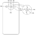
스마트 디바이스(100)에는 디스플레이부(151), 제1 및 제2 음향 출력부(152a, 152b), 근접 센서(141), 조도 센서(142), 광 출력부(154), 제1 및 제2 카메라(121a, 121b), 제1 및 제2 조작유닛(123a, 123b), 마이크로폰(122), 인터페이스부(160) 등이 구비될 수 있다.The
이하에서는, 도 2 및 도 3에 도시된 바와 같이, 스마트 디바이스(100) 몸체의 전면에 디스플레이부(151), 제1 음향 출력부(152a), 근접 센서(141), 조도 센서(142), 광 출력부(154), 제1 카메라(121a) 및 제1 조작유닛(123a)이 배치되고, 몸체의 측면에 제2 조작유닛(123b), 마이크로폰(122) 및 인터페이스부(160)이 배치되며, 몸체의 후면에 제2 음향 출력부(152b) 및 제2 카메라(121b)가 배치된 스마트 디바이스(100)를 일 예로 들어 설명한다.2 and 3, the
다만, 이들 구성은 이러한 배치에 한정되는 것은 아니다. 이들 구성은 필요에 따라 제외 또는 대체되거나, 다른 면에 배치될 수 있다. 예를 들어, 스마트 디바이스(100)의 몸체의 전면에는 제1 조작유닛(123a)이 구비되지 않을 수 있으며, 제2 음향 출력부(152b)는 몸체의 후면이 아닌 몸체의 측면에 구비될 수 있다.However, these configurations are not limited to this arrangement. These configurations may be excluded or replaced as needed, or placed on different planes. For example, the
디스플레이부(151)는 스마트 디바이스(100)에서 처리되는 정보를 표시(출력)한다. 예를 들어, 디스플레이부(151)는 스마트 디바이스(100)에서 구동되는 응용 프로그램의 실행화면 정보, 또는 이러한 실행화면 정보에 따른 UI(User Interface), GUI(Graphic User Interface) 정보를 표시할 수 있다. 또한, 스마트 디바이스(100)가 보조장치에 의해 사용자의 머리에 착용될 때, 디스플레이부(151)는 가상현실을 위한 입체영상을 사용자에게 제공할 수 있다. The
디스플레이부(151)는 액정 디스플레이(liquid crystal display, LCD), 박막 트랜지스터 액정 디스플레이(thin film transistor-liquid crystal display, TFT LCD), 유기 발광 다이오드(organic light-emitting diode, OLED), 플렉서블 디스플레이(flexible display), 3차원 디스플레이(3D display), 전자잉크 디스플레이(e-ink display) 중에서 적어도 하나를 포함할 수 있다. 디스플레이부(151)는 디스플레이 모듈(도시안됨)과 상기 디스플레이 모듈을 커버하는 윈도우(151a)를 포함할 수 있다. 디스플레이 모듈은 앞서 설명된 바와 같은 LCD, OLED와 같은 디스플레이 소자로 이루어질 수 있으며, 실제적으로 화상정보를 표시하는 구성요소이다. 윈도우(151a)는 디스플레이 모듈의 사용자에게 노출되는 부분에 배치될 수 있으며, 상기 디스플레이 모듈을 외부로부터 보호할 수 있다. 이러한 보호기능이외에도 윈도우(151a)는 이를 통해 디스플레이 모듈에 표시되는 정보를 사용에게 보여지게 허용해야 한다. 따라서, 윈도우(151a)는 적절한 강도 및 투명도를 갖는 재질로 이루어질 수 있다. 또한, 윈도우(151a)의 배면에 디스플레이 모듈이 직접적으로 부착될 수 있다. 디스플레이 모듈은 여러가지 방법으로 윈도우(151)에 직접 부착될 수 있으며, 접착제가 직접적 부착을 위해 가장 편리하게 사용될 수 있다. The
또한, 디스플레이부(151)는 스마트 디바이스(100)의 구현 형태에 따라 2개 이상 존재할 수 있다. 이 경우, 스마트 디바이스(100)에는 복수의 디스플레이부들이 하나의 면에 이격되거나 일체로 배치될 수 있고, 또한 서로 다른 면에 각각 배치될 수도 있다.In addition, the
디스플레이부(151)는 터치 방식에 의하여 제어 명령을 입력 받을 수 있도록, 디스플레이부(151)에 대한 터치를 감지하는 터치센서(미도시)를 포함할 수 있다. 상기 터치 센서는 저항막 방식, 정전용량 방식, 적외선 방식, 초음파 방식, 자기장 방식 등 여러 가지 터치방식 중 적어도 하나를 이용할 수 있다. 일 예로서, 저항막방식 및 정전용량 방식에서와 같이, 터치 센서는 터치 스크린의 특정 부위에 가해진 압력 또는 특정 부위에 발생하는 정전 용량 등의 변화를 전기적인 입력신호로 변환하도록 구성될 수 있다. 디스플레이부(151)는 터치 센서와 함께 스마트 디바이스에서 일종의 터치입력장치인 터치스크린을 구성할 수 있다. 디스플레이부(151)는 사용자 인터페이스인 터치스크린으로 작동하면서 동시에 소정의 화상정보를 표시할 수 있다. 즉, 디스플레이부(151)는 출력부(150) 뿐만 아니라 입력부(120)으로써도 기능할 수 있다. 디스플레이부(151)에 대하여 터치가 이루어지면, 터치센서는 상기 터치를 감지하고, 제어부(180)는 이에 근거하여 상기 터치에 대응하는 제어명령을 발생시키도록 이루어질 수 있다. 터치 방식에 의하여 입력되는 내용은 문자 또는 숫자이거나, 각종 모드에서의 지시 또는 지정 가능한 메뉴항목 등일 수 있다.The
터치센서는, 터치패턴을 구비하는 필름 형태로 구성되어 윈도우(151a)와 윈도우(151a)의 배면상의 디스플레이 모듈사이에 배치되거나, 윈도우(151a)의 배면에 직접 패터닝되는 메탈 와이어가 될 수도 있다. 또는, 터치센서는 디스플레이 모듈와 일체로 형성될 수 있다. 예를 들어, 터치센서는, 디스플레이 모듈의 기판 상에 배치되거나, 디스플레이 모듈의 내부에 구비될 수 있다.The touch sensor may be formed of a film having a touch pattern and disposed between the
이처럼, 디스플레이부(151)는 터치센서와 함께 터치 스크린을 형성할 수 있으며, 이 경우에 터치 스크린은 사용자 입력부(123, 도 1 참조)로 기능할 수 있다. 필요에 따라, 터치 스크린인 디스플레이부(151)에 인접하게 물리적 키(예를 들어 푸쉬 키)가 사용자 입력부(123)로써 사용자의 편리한 입력을 위해 추가적으로 제공될 수도 있다.In this way, the
제 1 음향 출력부(152a)는 통화음을 사용자의 귀에 전달시키는 리시버(receiver)로 구현될 수 있으며, 제2 음향 출력부(152b)는 각종 알람음이나 멀티미디어의 재생음을 출력하는 라우드 스피커(loud speaker)의 형태로 구현될 수 있다.The first
디스플레이부(151)의 윈도우(151a)에는 제1 음향 출력부(152a)로부터 발생되는 사운드의 방출을 위한 음향홀이 형성될 수 있다. 다만, 본 발명은 이에 한정되는 것은 아니고, 상기 사운드는 구조물 간의 조립틈(예를 들어, 윈도우(151a)와 프론트 케이스(101) 간의 틈)을 따라 방출되도록 구성될 수 있다. 이 경우, 외관상 음향 출력을 위하여 독립적으로 형성되는 홀이 보이지 않거나 숨겨져 스마트 디바이스(100)의 외관이 보다 심플해질 수 있다.The
광 출력부(154)는 이벤트의 발생시 이를 알리기 위한 빛을 출력하도록 이루어진다. 상기 이벤트의 예로는 메시지 수신, 호 신호 수신, 부재중 전화, 알람, 일정 알림, 이메일 수신, 애플리케이션을 통한 정보 수신 등을 들 수 있다. 제어부(180)는 사용자의 이벤트 확인이 감지되면, 빛의 출력이 종료되도록 광 출력부(154)를 제어할 수 있다.The
제1 카메라(121a)는 촬영 모드 또는 화상통화 모드에서 이미지 센서에 의해 얻어지는 정지영상 또는 동영상의 화상 프레임을 처리한다. 처리된 화상 프레임은 디스플레이부(151)에 표시될 수 있으며, 메모리(170)에 저장될 수 있다.The
제1 및 제2 조작유닛(123a, 123b)은 스마트 디바이스(100)의 동작을 제어하기 위한 명령을 입력 받기 위해 조작되는 사용자 입력부(123)의 일 예로서, 조작부(manipulating portion)로도 통칭될 수 있다. 제1 및 제2 조작유닛(123a, 123b)은 터치, 푸시, 스크롤 등 사용자가 촉각적인 느낌을 받으면서 조작하게 되는 방식(tactile manner)이라면 어떤 방식이든 채용될 수 있다. 또한, 제1 및 제2 조작유닛(123a, 123b)은 근접 터치(proximity touch), 호버링(hovering) 터치 등을 통해서 사용자의 촉각적인 느낌이 없이 조작하게 되는 방식으로도 채용될 수 있다.The first and
본 도면에서는 제1 조작유닛(123a)이 터치키(touch key)인 것으로 예시하나, 본 발명이 이에 한정되는 것은 아니다. 예를 들어, 제1 조작유닛(123a)은 푸시키(mechanical key)가 되거나, 터치키와 푸시키의 조합으로 구성될 수 있다.In this figure, the
제1 및 제2 조작유닛(123a, 123b)에 의하여 입력되는 내용은 다양하게 설정될 수 있다. 예를 들어, 제1 조작유닛(123a)은 메뉴, 홈키, 취소, 검색 등의 명령을 입력 받고, 제2 조작유닛(123b)은 제1 또는 제2 음향 출력부(152a, 152b)에서 출력되는 음향의 크기 조절, 디스플레이부(151)의 터치 인식 모드로의 전환 등의 명령을 입력 받을 수 있다.The contents input by the first and
상기 조작유닛(123a, 123b)은 앞서 설명된 디스플레이부(151)에 적용된 터치 스크린과 유사한 구조의 터치입력장치로 이루어질 수 있다. 조작유닛(123a, 123b)은 터치스크린과는 달리 화상정보의 표시없이 단순하게 명령만을 입력하도록 구성되며, 이와 같은 조작유닛에 적용된 터치입력장치는 터치패드라고 불릴 수 있다. The
한편, 스마트 디바이스(100) 몸체의 후면에는 사용자 입력부(123)의 다른 일 예로서, 후면 입력부(미도시)가 구비될 수 있다. 이러한 후면 입력부는 스마트 디바이스(100)의 동작을 제어하기 위한 명령을 입력 받기 위해 조작되는 것으로서, 입력되는 내용은 다양하게 설정될 수 있다. 예를 들어, 전원의 온/오프, 시작, 종료, 스크롤 등과 같은 명령, 제1 및 제2 음향 출력부(152a, 152b)에서 출력되는 음향의 크기 조절, 디스플레이부(151)의 터치 인식 모드로의 전환 등과 같은 명령을 입력 받을 수 있다. 후면 입력부는 터치입력, 푸시입력 또는 이들의 조합에 의한 입력이 가능한 형태로 구현될 수 있다.On the other hand, a rear input unit (not shown) may be provided on the rear surface of the body of the
후면 입력부는 디바이스(100) 몸체의 두께방향으로 전면의 디스플레이부(151)와 중첩되게 배치될 수 있다. 일 예로, 사용자가 디바이스(100) 몸체를 한 손으로 쥐었을 때 검지를 이용하여 용이하게 조작 가능하도록, 후면 입력부는 디바이스(100) 몸체의 후면 상단부에 배치될 수 있다. 다만, 본 발명은 반드시 이에 한정되는 것은 아니며, 후면 입력부의 위치는 변경될 수 있다.The rear input unit may be disposed so as to overlap the
이처럼 디바이스(100) 몸체의 후면에 후면 입력부가 구비되는 경우, 이를 이용한 새로운 형태의 유저 인터페이스가 구현될 수 있다. 또한, 앞서 설명한 터치 스크린 또는 후면 입력부가 디바이스(100) 몸체의 전면에 구비되는 제1 조작유닛(123a)의 적어도 일부 기능을 대체하여, 상기 몸체의 전면에 제1 조작유닛(123a)이 미배치되는 경우, 디스플레이부(151)가 보다 큰 화면으로 구성될 수 있다.When a rear input unit is provided on the rear surface of the
한편, 스마트 디바이스(100)에는 사용자의 지문을 인식하는 지문인식센서가 구비될 수 있으며, 제어부(180)는 지문인식센서를 통하여 감지되는 지문정보를 인증수단으로 이용할 수 있다. 상기 지문인식센서는 디스플레이부(151) 또는 사용자 입력부(123)에 내장될 수 있다.Meanwhile, the
마이크로폰(122)은 사용자의 음성, 기타 소리 등을 입력 받도록 이루어진다. 마이크로폰(122)은 복수의 개소에 구비되어 스테레오 음향을 입력 받도록 구성될 수 있다.The
인터페이스부(160)는 스마트 디바이스(100)를 외부기기와 연결시킬 수 있는 통로가 된다. 예를 들어, 인터페이스부(160)는 다른 장치(예를 들어, 이어폰, 외장 스피커)와의 연결을 위한 접속단자(예를 들어, USB 포트), 근거리 통신을 위한 포트[예를 들어, 적외선 포트(IrDA Port), 블루투스 포트(Bluetooth Port), 무선 랜 포트(Wireless LAN Port) 등], 또는 스마트 디바이스(100)에 전원을 공급하기 위한 전원공급단자 중 적어도 하나일 수 있다. 이러한 인터페이스부(160)는 SIM(Subscriber Identification Module) 또는 UIM(User Identity Module), 정보 저장을 위한 메모리 카드 등의 외장형 카드를 수용하는 소켓의 형태로 구현될 수도 있다.The
스마트 디바이스(100) 몸체의 후면에는 제2카메라(121b)가 배치될 수 있다. 이 경우, 제2카메라(121b)는 제1카메라(121a)와 실질적으로 반대되는 촬영 방향을 가지게 된다.And a
제2카메라(121b)는 적어도 하나의 라인을 따라 배열되는 복수의 렌즈를 포함할 수 있다. 복수의 렌즈는 행렬(matrix) 형식으로 배열될 수도 있다. 이러한 카메라는, 어레이 카메라로 명명될 수 있다. 제2카메라(121b)가 어레이 카메라로 구성되는 경우, 복수의 렌즈를 이용하여 다양한 방식으로 영상을 촬영할 수 있으며, 보다 나은 품질의 영상을 획득할 수 있다. 제1 카메라(121a)도 이와 같은 어레이 카메라로 구성될 수 있다. The
플래시(124)는 제2카메라(121b)에 인접하게 배치될 수 있다. 플래시(124)는 제2카메라(121b)로 피사체를 촬영하는 경우에 피사체를 향하여 빛을 비추게 된다. 또한, 스마트 디바이스(100)는 제 2 카메라(121b)에 인접하게 배치되는 거리센서(144)를 포함할 수 있다. 거리센서(144)는 스마트 디바이스(100)에 전방에 배치되는 근접센서(141)와 유사하게 소정 물체와 디바이스(100) 사이의 거리를 측정할 수 있다. 측정된 거리는 제 2 카메라(121b)에서 상기 물체에 대한 적절한 화상을 획득하는데 이용될 수 있으며, 또한 다른 여러가지 목적으로 활용될 수도 있다. The
스마트 디바이스(100) 몸체에는 제2 음향 출력부(152b)가 추가로 배치될 수 있다. 제2 음향 출력부(152b)는 제1 음향 출력부(152a)와 함께 스테레오 기능을 구현할 수 있으며, 통화시 스피커폰 모드의 구현을 위하여 사용될 수도 있다.A second
스마트 디바이스(100) 몸체에는 무선 통신을 위한 적어도 하나의 안테나가 구비될 수 있다. 안테나는 상기 몸체에 내장되거나, 케이스에 형성될 수 있다. 예를 들어, 방송 수신 모듈(111, 도 1a 참조)의 일부를 이루는 안테나는 상기 몸체에서 인출 가능하게 구성될 수 있다. 또는, 안테나는 필름 타입으로 형성되어 후면 커버(103)의 내측면에 부착될 수도 있고, 도전성 재질을 포함하는 케이스가 안테나로서 기능하도록 구성될 수도 있다.The
스마트 디바이스(100) 몸체에는 스마트 디바이스(100)에 전원을 공급하기 위한 전원 공급부(190, 도 1 참조)가 구비된다. 전원 공급부(190)는 상기 몸체에 내장되거나, 상기 몸체의 외부에서 착탈 가능하게 구성되는 배터리(191)를 포함할 수 있다.The
배터리(191)는 인터페이스부(160)에 연결되는 전원 케이블을 통하여 전원을 공급받도록 구성될 수 있다. 또한, 배터리(191)는 무선충전기기를 통하여 무선충전 가능하도록 구성될 수도 있다. 상기 무선충전은 자기유도방식 또는 공진방식(자기공명방식)에 의하여 구현될 수 있다.The
본 도면에서는 후면 커버(103)가 배터리(191)를 덮도록 리어 케이스(102)에 결합되어 배터리(191)의 이탈을 제한하고, 배터리(191)를 외부 충격과 이물질로부터 보호하도록 구성된 것을 예시하고 있다. 배터리(191)가 몸체에 착탈 가능하게 구성되는 경우, 후면 커버(103)는 리어 케이스(102)에 착탈 가능하게 결합될 수 있다.In the figure, the
비록 도 2 및 도 3에는 도시되지 않았으나, 기판은 케이스들(101,102)내에 설치될 수 있으며, 각종 전자부품, 특히 제어부(180)를 구성하는 각종 프로세서들이 이들을 보조하는 다른 회로 및 소자들과 함께 장착되는 구성요소이다. 도 1에 도시된 각 구성요소들(110-190)은 제어부(180)에 의해 제어될 수 있도록 상기 기판에 직접 설치되거나, 상기 케이스(101,102)에 또는 그 내부에 설치되어 상기 기판에 전기적으로 연결된다. 예를 들어, 비록 외부에 노출되어 있지만, 윈도우(151)(즉, 터치센서) 및 디스플레이 모듈은 각각 배선을 통해 상기 기판에 연결될 수 있다. 따라서, 제어부(180)는 제어기(controller), 제어장치(controlling device)와 같은 다양한 명칭으로 불릴 수 있으며, 스마트 디바이스(100)의 모든 구성요소들을 제어할 수 있다. 이와 같은 제어되는 구성요소는 도 1에 포함된 구성요소 뿐만 아니라 다음에서 설명될 다른 구성요소들도 포함한다. 따라서, 제어부(180)은 다른 구성요소들의 작동을 제어함으로써 후술되는 본 출원의 제어방법을 적절하게 수행하는 실제적인 구성요소가 될 수 있다. 이러한 이유로, 상기 제어방법에서 수행되는 모든 세부적인 단계들은 모두 제어부(180)의 특징이 될 수 있다. Although not shown in FIGS. 2 and 3, the substrate may be installed in the
스마트 디바이스(100)에는 외관을 보호하거나, 스마트 디바이스(100)의 기능을 보조 또는 확장시키는 액세서리가 추가될 수 있다. 이러한 액세서리의 일 예로, 스마트 디바이스(100)의 적어도 일면을 덮거나 수용하는 커버 또는 파우치를 들 수 있다. 커버 또는 파우치는 디스플레이부(151)와 연동되어 스마트 디바이스(100)의 기능을 확장시키도록 구성될 수 있다. 액세서리의 다른 일 예로, 터치 스크린에 대한 터치입력을 보조 또는 확장하기 위한 터치펜을 들 수 있다.The
한편, 앞서 설명된 바와 같이, 스마트 디바이스(100)는 작은 크기를 가지면서도 다양한 기능을 수행할 수 있는 능력을 가질 수 있다. 따라서, 스마트 디바이스(100)는 상기 디바이스(100)주위의 환경에 대한 다양한 정보를 측정하고 측정된 정보에 기초한 부가적인 기능을 사용자에게 제공할 수 있다. 보다 상세하게는, 최근에는 건강에 대한 관심이 증가되고 있으므로, 스마트 디바이스(100)는 다양한 신체정보를 측정하고 측정된 정보에 기초하여 사람의 건강 상태를 확인하고 관리할 수 있다. 특히, 체온은 사람의 신체정보에서 기본이 되므로, 건강을 관리하기 위해서는 체온이 필수불가결하게 측정될 필요가 있다. 이러한 이유로, 스마트 디바이스(100)는 도 2 및 도 3에 도시된 바와 같이, 신체를 포함하여 소정 물체의 온도를 측정하도록 구성되는 온도센서(143:143a,143b)를 포함할 수 있다. 또한, 온도센서(143)은 신체 이외의 다른 물체의 온도도 함께 측정할 수 있으므로, 이러한 측정된 온도에 기초하여 건강관리에 추가적으로 다양한 기능을 사용자에게 제공할 수도 있다. Meanwhile, as described above, the
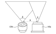
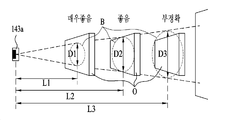
도 4는 온도센서의 측정각 및 거리에 따른 측정범위를 보여주는 개략도이며, 도 5는 카메라의 화각에 의한 촬영범위 및 온도센서의 측정각에 의한 측정범위를 보여주는 평면도이다. 또한, 도 6은 스마트 디바이스에 최적으로 배치된 카메라 및 온도센서를 보여주는 배면도이며, 도 7은 최적으로 배치된 카메라의 화각 및 온도센서의 측정각의 일예를 보여주는 개략도이다. 끝으로, 도 8은 최적의 배치에 따른 촬영범위 및 측정범위를 보여주는 평면도이다. 이들 도면을 참조하여 온도센서(143)가 다음에서 보다 상세하게 설명된다. 또한, 도 2 및 도 3은 디바이스(100)의 전체적인 구조를 잘 보여주므로, 설명의 편의를 위해 상기 도면들과 함께 다음의 설명에서 참조된다. FIG. 4 is a schematic view showing a measurement range according to a measurement angle and a distance of the temperature sensor, FIG. 5 is a plan view showing a measurement range according to a measurement angle of the temperature sensor, and a shooting range according to the angle of view of the camera. Fig. 6 is a rear view showing a camera and a temperature sensor optimally arranged in a smart device, and Fig. 7 is a schematic diagram showing an example of a measurement angle of a camera and an angle of view of an optimally arranged camera. Finally, FIG. 8 is a plan view showing a photographing range and a measuring range according to the optimal arrangement. With reference to these figures, the
먼저 온도센서(143)는 접촉식 및 비접촉식 센서로 분류될 수 있다. 접촉식 센서는 물체에 직접적으로 접촉되며, 상기 물체와 열평형상태에 도달한 뒤 온도를 측정할 수 있다. 비접촉식 센서는 물체에서 방사되는 열 에너지를 이격된 위치에서 검출하여 온도를 측정할 수 있다. 접촉식 센서는 물체의 열에너지가 센서 자체로 이동하므로 물체의 온도변화를 야기시킬 수 있다. 따라서, 접촉식 센서는 정확한 온도 측정이 어려울 수 있는 반면, 단순한 구조로 인해 가격이 싸다. 비접촉식 센서는 직접적인 열접촉을 이용하지 않으므로, 접촉시 센서에서와 같은 문제를 일으키지 않으나, 접촉식 센서에 비해 상대적으로 비싸다. First, the
도 3에 도시된 바와 같이, 온도 센서(143)는 스마트 디바이스(100)의 후방부에 설치되는 제 1 센서(143a)를 포함할 수 있다. 제 1 센서(143a)는 디스플레이부(151)에 대향되게 배치되므로, 사용자는 제 1 센서(143a)에서 측정된 온도를 실시간으로 디스플레이부(151)를 통해 확인할 수 있다. 따라서, 제 1 센서(143a)는 스마트 디바이스(100)와 접촉하는 물체뿐만 아니라 이로부터 이격된 물체 둘 다의 온도를 측정하기에 유리할 수 있다. 이러한 이유로, 제 1 센서(143a)는 떨어져 있는 물체의 온도를 측정할 수 있는 비 접촉식 센서로 이루어질 수 있다. 또한, 제 1 센서(143a)는 앞서 설명된 바와 같이 디바이스(100)과 직접 접촉하는 물체의 온도 측정에도 적용될 수 있으므로, 필요한 경우, 접촉식 센서로도 이루어질 수 있다. 한편, 도 2에 도시된 바와 같이, 온도센서(143)는 스마트 디바이스(100)의 전방부에 설치되는 제 2 센서(143b)를 포함할 수도 있다. 스마트 디바이스(100)의 전방부는 통화시에 사용자의 얼굴에 직접 접촉할 수 있다. 따라서, 제 2 센서(143b)는 스마트 디바이스(100)에 접촉하는 물체, 특히 신체의 온도를 측정하기에 유리하며, 이에 따라 접촉식 센서로 이루어질 수 있다. 만일 필요한 경우, 제 2 센서(143b)는 제 1 센서(143a)와 마찬가지로 비접촉식 센서로 이루어질 수도 있다. As shown in FIG. 3, the
공지된 바와 같이, 카메라(121)는 이격된 물체의 화상을 획득하도록 구성되며, 센서 및 렌즈의 구조, 이들 센서 및 렌즈로 빛을 도입하는 개구부의 형상과 같은 구조적 특성으로 인해 소정의 화각(FOV:Field of View / AOV:Angle of View)를 가질 수 있다. 상기 화각은 카메라(121)가 이미지를 획득할 수 있는 각도를 의미한다. 화각은 카메라 또는 이의 렌즈의 고유한 값이며, 이러한 화각에 의해 거리에 따라 카메라(121)에서 화상의 촬영범위 또는 획득범위(A)(도 5 참조)가 기하학적으로 달라질 수 있다. 이러한 촬영범위(A)는 대체적으로 카메라(121)의 중심축(C)에 대해 수직한 원형평면으로 구현될 수 있으나, 카메라 또는 렌즈의 특성에 따라 다른 형상의 평면이 될 수도 있다. 비 접촉식 온도센서(143)도 카메라(121)와 유사한 구조적 특성을 가지므로, 카메라의 화각과 유사하게, 소정의 측정각을 가질 수 있으며, 도 4에는 이러한 측정각(α) 및 이에 따른 온도센서(143)의 특성이 잘 도시된다. 도 4는 먼저 비접촉식 센서로 가정된 제 1 센서(143a)와 관련된 특성을 도시하고 있으너, 만일 제 2 센서(143b)가 비접촉식 센서로 이루어지면, 도 4의 내용은 변형없이 그와 같은 제 2 센서(143b)에도 적용될 수 있다. 도 4를 참조하면, 비 접촉식 온도센서(143)는 상기 센서(143)가 온도를 측정할 수 있는 각도인 측정각(α)을 가질 수 있다. 온도센서(143)으로부터 거리가 증가될 수록 측정각(α)에 의해 발생되는 기하학적 관계로 인해, 측정범위(B)도 증가될 수 있다. 마찬가지로, 상기 거리가 감소될수록, 측정범위(B)도 감소될 수 있다. 또한, 카메라(121)과 마찬가지로, 온도센서(143)의 측정범위도 대체적으로 이의 중심축(C)에 수직한 원형 또는 다른 형상의 평면으로 구현될 수 있다. 예를 들어, 도 4에 도시된 바와 같이, 온도센서(143)로부터 거리가 거리(L1)으로부터 거리(L2) 또는 거리(L3)로 증가되면, 측정범위(B)의 직경도 직경(D1)으로부터 직경(D2) 또는 직경 (D3)로 증가될 수 있다. 즉, 비 접촉식 온도센서(143)은 상기 센서(143)으로부터 소정 물체, 즉 이의 온도가 상기 센서(143)에 의해 측정되는 물체까지의 거리에 따라 변화되는 측정범위(B)를 가질 수 있다. 또한, 측정범위(B)는 소정의 크기의 평면으로 구현되므로, 상기 측정범위(B)는 이의 온도가 상기 센서(143)에 의해 측정될 수 있는 면적으로 정의될 수 있다. 더 나아가, 온도센서(143)는 물체의 온도를 감지함으로써 해당 물체의 온도를 측정할 수 있으므로, 온도 센서(143)의 측정각(C) 및 측정범위(B)는 감지각(α) 및 감지범위(B)로서 표현될 수 있다. As is well known, the
앞서 설명된 바와 같이, 디바이스(100)의 후방에 배치된 제 2 카메라(121b)와 제 1 센서(143a)가 이용되면, 사용자는 소정 물체의 측정된 온도를 디스플레이부(151)에서 해당 물체에 대한 화상과 함께 실시간을 확인할 수 있다. 이러한 실시간적인 측정 및 확인에 의해 소정물체에 대한 온도 측정은 상당히 편리하게 수행될 수 있다. 이와 같은 편리한 측정을 위해서는 물체가 제 2 카메라(121b)에 의해 획득된 화상내에 적절하게 배치되면, 즉 물체가 제 2 카메라(121b)의 화각내에 배치되면, 제 1 센서(143a)가 상기 화상내의 물체의 온도를 측정할 수 있어야 한다. 즉, 제 2 카메라(121b)의 촬영범위(A)와 제 1 온도센서(143a)의 측정범위(B)가 적어도 서로 겹쳐질 필요가 있다. 또한, 대개의 경우, 제 1 온도센서(143a)는 획득된 화상의 일부에 해당되는 물체의 온도를 측정하므로, 측정범위(B)는 촬영범위(A)보다 클 필요가 없다. 따라서, 소정거리에서 상기 측정범위(B)는 촬영범위(A)보다 작게 형성되고 이에 따라 촬영범위(A)내에 포함되는 것이 바람직할 수 있다. 더 나아가, 일반적으로 사용자는 온도를 측정하기 위해 상기 물체를 획득되는 화상의 중앙부에 배치하므로, 상기 측정범위(B)와 촬영범위(A)는 서로 동심상으로 배치되는 것이 바람직할 수 있다. 따라서, 정확하고 편리한 온도 측정을 위해서는 상술된 조건들중 적어도 하나를 만족하도록 제 2 카메라(121b)와 제 1 센서(143a)가 구성될 수 있다. 즉, 제 2 카메라(121b)와 제 1 센서(143a)는, 촬영범위(A)와 측정범위(B)가 서로 겹쳐지거나 동심상으로 배치되거나, 또는 측정범위(B)가 촬영범위(A)내에 포함되도록, 구성될 수 있다. 만일 제 2 카메라(121b)와 제 1 센서(143a)가 부적절하게 구성되면, 도 5에 도시된 바와 같이, 획득된 화상내의 물체(O)로부터 측정범위(B)가 실질적으로 이격될 수 있다. 따라서, 제 1 센서(143a)는 물체(O)의 온도를 적절하게 측정할 수 없다. As described above, when the
실제적으로, 상술된 조건들을 만족시키기 위해, 먼저 도 6에 도시된 바와 같이, 온도센서(143), 즉 제 1 센서(143a)는 카메라(121), 즉 제 2 카메라(121b)에 인접하게 배치될 수 있다. 보다 상세하게는, 제 1 센서(143a)는 제 2 카메라(121b)로부터 소정의 반경(R)내에 배치될 수 있다. 실제적으로 상기 반경(R)은 8mm가 될 수 있다. 또한, 상술된 조건들을 만족시키기 위해, 도 7에 도시된 바와 같이, 제 1 센서(143a)의 측정각(α)과 제 2 카메라(121b)의 화각(β)도 적절하게 조절될 필요가 있다. 실제적으로 측정각(α)는 45°로, 화각(β)은 80°로 설정될 수 있다. 이와 같은 인접 배치 및 측정각(α)/화각(β)의 조절에 의해 도 8에 도시된 바와 같이, 측정범위(B)는 촬영범위(A)와 겹치며, 촬영범위(A)에 포함되며, 동시에 촬영범위(A)와 동심상으로 배치될 수 있다. 따라서, 디바이스(100)는 제 2 카메라(121b)를 이용하여 소정 물체(O)에 대한 화상을 획득하고 제 1 센서(143a)를 이용하여 바로 해당 물체(O)에 대한 온도를 정확하고 편리하게 측정할 수 있다.6, the
한편, 앞서 설명된 스마트 디바이스(100)는 온도센서(143)의 구성을 최적화함으로써 정확하고 편리하게 온도측정을 수행할 수 있다. 그러나, 보다 향상된 기능을 제공하기 위해서는 온도센서(143) 및 이와 관련된 구조들은 디바이스(100)의 구조 및 특성을 고려한 적절한 제어에 뒷받침될 필요가 있다. 또한, 스마트 디바이스(100)는 의도된 기능을 구현함에 있어서 사용자와의 상호작용을 기본적으로 수반한다. 따라서, 다양한 제어의 최적화는 사용자의 사용환경 및 인터페이스(user environment and user interface)의 향상을 포함하여 의도된 기능적 향상을 보다 효과적이고 효율적으로 달성할 수 있으며, 더 나아가 사용의 용이함 및 편리함등과 같은 스마트 디바이스(100)에 대한 사용자의 경험(user experience)도 함께 현저하게 향상시킬 수 있다. 이와 같은 이유로, 도 1-도 8에 도시된 스마트 디바이스(100)에 대한 제어방법이 개발되었으며, 다음에서 도 1-도 8에 추가적으로 관련된 도면들을 참조하여 설명된다. 특별히 반대되는 설명이 없는 한 도 1-도 8 및 이에 대한 설명들은 다음의 제어방법의 설명 및 도면들에 기본적으로 포함되고 참조된다. On the other hand, the
또한, 다음에서 설명되는 제어방법들은 앞서 도 1 - 도 8를 참조하여 설명된 구성요소, 즉 다양한 부품들의 작동을 제어하며, 이러한 작동에 기초하에 의도된 기능들을 제공할 수 있다. 따라서, 제어방법과 관련된 작동 및 기능들은 제어방법의 특징 뿐만 아니라 모두 관련된 해당 구조적 구성요소들의 특징으로도 간주될 수 있다. 특히, 제어부 또는 프로세서(180)는 제어기(controller) 및 제어장치(controlling device)와 같은 다양한 명칭으로 불릴 수 있으며, 소정의 작동을 수행하기 위해 디스플레이 디바이스(100)의 모든 구성요소들을 제어할 수 있다. 따라서, 제어부(180)가 실질적으로 본 출원에서 다음에 설명되는 모든 방법 및 모드들을 실질적으로 제어하며, 이에 따라 이후 설명될 모든 단계들은 제어부(180)의 특징이 될 수 있다. 이러한 이유로, 특별한 설명이 없는 경우에도, 다음의 단계들 및 모드들은 제어부(180)에 의해 수행되고 제어된다고 이해되어져야 한다. In addition, the control methods described below control the operation of the components described above with reference to Figs. 1-8, i.e., the various components, and can provide the intended functions based on such operation. Thus, the operations and functions associated with the control method can be regarded not only as a feature of the control method, but also as a feature of the respective structural components involved. In particular, the controller or
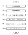
먼저, 도 9는 본 출원에서 설명되는 스마트 디바이스의 제어방법을 보여주는 순서도이며, 도 10은 도 9의 검출단계를 보다 상세하게 보여주는 순서도이다. 도 11은 거리에 따른 측정범위 및 물체의 크기사이의 관계를 보여주는 개략도이며, 도 12는 거리에 따른 측정범위 및 물체의 크기사이의 관계의 일 예를 보여주는 평면도이다. 끝으로, 도 13은 도 9에 따른 제어방법의 일 예를 보여주는 평면도이다. FIG. 9 is a flowchart showing a control method of a smart device described in the present application, and FIG. 10 is a flowchart showing the detection step of FIG. 9 in more detail. Fig. 11 is a schematic view showing a relationship between a measurement range and an object size along a distance, and Fig. 12 is a plan view showing an example of a relationship between a measurement range and an object size according to distance. Finally, FIG. 13 is a plan view showing an example of the control method according to FIG.
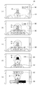
앞서 설명된 바와 같이, 스마트 디바이스(100)의 후방부에 배치된 제 2 카메라(121b)와 제 1 센서(143a)는 디스플레이부(151)를 통해 확인가능한 실시간적이고 편리한 온도 측정을 수행할 수 있다. 따라서, 도 9에 따른 제어방법(S10)은 소정 물체에 대한 화상과 연계하여 스마트 디바이스(100)로부터 떨어진 물체의 온도를 측정하는 단계들을 포함할 수 있다. As described above, the
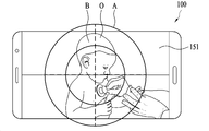
상기 제어방법(S10)에 있어서, 먼저 스마트 디바이스(100)는 온도 측정을 위해 소정 물체의 화상을 획득할 수 있다(S11). 상기 획득단계(S11)에서 스마트 디바이스(100), 즉 제어부(180)는 이의 후방부에 배치된 제 2 카메라(121b)를 이용하여 온도가 측정되는 물체(O)의 화상을 획득할 수 있다. 보다 상세하게는, 도 13(a)의 예에서 나타나는 바와 같이, 스마트 디바이스(100)는 디스플레이부(151)에 온도 측정을 위한 메뉴 또는 옵션을 제공할 수 있으며, 이러한 메뉴 또는 옵션(M1)은 아이콘 또는 버튼과 같은 선택가능한 객체로서 구현될 수 있다. 사용자가 상기 메뉴 또는 옵션(M1)를 선택함으로써 스마트 디바이스(100)는 온도측정의 명령을 수신하며 물체(O)에 대한 온도 측정을 시작할 수 있다. 온도 측정이 시작되면, 스마트 디바이스(100)는 제 2 카메라(121b)를 이용하여 물체(O)의 화상을 획득하며, 도시된 바와 같이 획득된 화상은 일반적으로 상기 물체(O)뿐만 아니라 물체(O) 주변의 배경도 함께 포함할 수 있다. In the control method (S10), the
상기 획득단계(S11)후, 스마트 디바이스(100)는 획득된 화상으로부터 물체(O)를 인식할 수 있다(S12). 앞서 설명된 바와 같이, 비 접촉식 온도 센서인 제 1 센서(143a)는 상기 센서(143a)와 물체(O)사이의 거리에 따라 변화되는 측정 또는 감지범위(B)를 갖는다. 나중에 보다 상세하게 설명되는 바와 같이, 이와 같은 변화가능한 감지범위(B)가 물체(O)내에 배치될 때, 온도 측정이 보다 정확하게 수행될 수 있다. 따라서, 감지 범위(B)가 물체(O)내에 배치되는지를 확인하기 위해서는 먼저 온도 측정을 받는 물체(O)가 명확하게 인식될 필요가 있다. 인식단계(S21)에서 스마트 디바이스(100)는 물체(O)의 인식을 위해 먼저 화상으로부터 물체(O)의 외형 또는 윤곽을 인식할 수 있다. 보다 상세하게는, 상기 인식단계(S12)에서, 스마트 디바이스(100)은 획득된 화상에서 중앙에 위치하거나 가장 큰 물체를 자동적으로 인식할 수 있다(S12a). 앞서 설명된 바와 같이, 사용자는 일반적으로 온도를 측정하기를 원하는 물체를 화상의 가운데 위치시키는 경향이 있다. 또한, 같은 이유로, 사용자는 온도를 측정하기를 원하는 물체가 가장 크게 되도록 화상을 획득하는 경향이 있다. 따라서, 사용자의 이러한 경향을 고려하여, 스마트 디바이스(100)는 중앙에 위치하거나 가장 큰 물체를 자동적으로 인식함으로써 보다 편리하게 온도측정을 진행할 수 있다. 도 13(a)에 도시된 바와 같이, 사용자는 자신이 온도를 측정하기를 원하는 물체(O), 즉 사람이 다른 물체들에 비해 가장 크게 화상의 중앙에 배치되도록 화상을 촬영하며, 이러한 물체(O)가 스마트 디바이스(100)에 의해 자동적으로 인식될 수 있다. 더 나아가, 상기 인식단계(S12)에서 스마트 디바이스(100)은 획득된 화상으로부터 사람의 신체를 자동적으로 인식할 수 있다(S12c). 도 13(a)에 도시된 바와 같이, 사람의 신체는 다른 물체들과 크게 구별되므로, 화상분석을 통해 사람의 신체는 쉽게 인식될 수 있다. 만일 사용자가 사람의 체온을 측정하기를 원하는 경우, 이러한 자동 인식에 의해 물체(O), 즉 사람의 신체는 화상의 중앙에 배치되거나 크게 확대되지 않아도 인식될 수 있으며, 이에 따라 온도측정이 보다 편리해질 수 있다. 또한, 상기 인식단계(S12)에서 스마트 디바이스(100)는 상기 사용자에 의해 지정된 물체(O)를 인식할 수 있다(S12b). 예를 들어, 도 13(a)에서 사용자는 자신이 온도를 측정하기를 원하는 물체(O)를 터치할 수 있으며, 디바이스(100)는 터치된 물체(O)를 화상분석을 통해 인식할 수 있다. 이러한 수동 인식에 의해 원하는 물체(O)가 보다 정확하게 인식될 수 있다. After the acquisition step S11, the
또한, 앞서 설명된 윤곽 검출에 추가적으로, 인식단계(S12)에서 디바이스(100)는 측정범위(B)와 비교될 수 있도록 인식된, 즉 윤곽이 확인된 물체(O)의 크기를 검출할 수 있다. 실체적으로, 비 접촉식 제 1 센서(143a)는 물체(O)의 표면으로 이의 온도를 측정하며, 제 2 카메라(121b)는 3차원이 아닌 2차원적, 평면적 화상을 얻는다. 즉, 제 1 센서(143a) 및 제 2 카메라(121b) 둘 다 소정 물체(O)의 체적이 아닌 2차원 표면을 촬영 및 측정의 대상으로 본다. 따라서, 물체(O)의 크기는 실제적으로 앞서 인식된 윤곽내의 표면적 또는 이의 크기를 의미하며, 특별한 설명없이도 이러한 정의는 다음의 모든 물체의 크기에 적용될 수 있다. 또한, 같은 이유로, 측정범위(B) 및 촬영범위(A)도 2차원적 표면적을 의미하며, 이러한 정의 역시도 다음의 모든 범위들(A,B)에 적용될 수 있다. 또한, 디비아스(100)는 고유한 특성에 해당하는 물체(O)의 현 위치에서 제 2 카메라(121b)의 촬영범위(B)의 크기, 즉 이의 실제적인 치수를 미리 알 수 있으므로, 상기 인식단계(S12)에서 디바이스(100)는 화상 분석을 통해, 상기 물체(O)의 실제 크기를 산출할 수 있다. 다른 한편, 디바이스(100)는 디스플레이부(151)에 표시되는 화상의 크기에 대한 물체(O)의 비율을 검출하고, 이에 따라 절대적인 크기대신에, 상기 화상크기에 대한 상대적인 물체(O)의 크기를 산출할 수도 있다.Further, in addition to the contour detection described above, in the recognition step S12, the
스마트 디바이스(100)는 또한, 상기 디바이스(100)로부터 물체(O)까지의 거리를 측정할 수 있다(S13). 상기 측정단계(S13)에서, 디바이스(100)는 거리센서(144)를 이용하여 상기 거리를 측정할 수 있다. 거리센서(144)는 예를 들어, 적외선을 방출하고 상기 물체(O)로부터 되돌아오는 적외선을 수신함으로써 디바이스(100)와 물체(O)사이의 거리를 측정할 수 있다. 만일 앞서 설명된 바와 같이, 상기 인식단계(S12)에서 물체(O)의 실제 크기를 산출하는 경우, 물체(O)의 현 위치에서의 촬영범위(A)의 실제적인 치수가 요구되며, 이러한 실제 치수를 알기 위해서는 상기 물체(O)까지의 거리가 요구될 수 있다. 따라서, 인식단계(S12)에서 물체(O)의 실제 크기를 산출하기 위해, 측정단계(S13)는 인식단계(S12)이전 또는 인식단계(S12)와 동시에 수행될 수 있다. 한편, 예를 들어, 만일 인식단계(S12)에서 물체(O)의 화상에 대한 상대적인 크기가 산출하는 경우, 실제적인 거리에 따른 촬영범위(A)가 필요하지 않을 수 있다. 따라서, 이러한 측정단계(S13)는 물체(O)가 인식된 후에 수행될 수 있다. The
스마트 디바이스(100)와 물체(O)사이의 거리가 측정되면, 스마트 디바이스(100)는 상기 측정된 거리에서의 제 1 센서(143a)의 측정범위(B)를 표시할 수 있다(S14). 상기 표시단계(S14)에서 디바이스(100)는 먼저 인식단계(S12)에서 인식된, 즉 윤곽이 확인된 물체(O)의 크기와 비교될 수 있도록 측정된 거리에서의 제 1 센서(143a)의 측정범위(B), 즉 이의 크기를 산출할 수 있다. 상기 촬영범위(A)와 마찬가지로, 측정범위(B)는 기 설정된 제 1 센서(143a)의 특성치이므로, 디비아스(100)는 기본적으로 거리에 따른 제 1 센서(143a)의 측정범위(B)의 크기들, 즉 이의 실제적인 치수들을 미리 알수 있다. 예를 들어, 거리에 따른 촬영범위(A) 뿐만 아니라 측정범위(B)들의 실제적인 값들은 메모리(170)에 테이블로 미리 저장되어 있을 수 있다. 따라서, 이러한 테이블을 참조함으로서 디비아스(100)는 측정된 거리에서의 측정범위(B)의 크기를 바로 확인할 수 있다. 또한, 이러한 테이블이 없더라도 디바이스(100), 즉 제어부(180)는 제 2 카메라(121b) 및 제 1 센서(143a)의 고유한 물성치(property), 예를 들어 화각 또는 측정각을 이용하여 측정된 거리에서의 촬영범위(A) 및 측정범위(B)를 계산할 수 있다. Once the distance between the
한편, 상기 획득단계(S11)에서, 획득된 화상의 크기는 디스플레이부(151)에 적절하게 표시되도록 상기 디스플레이부(151)의 화면 크기 또는 해상도에 맞게 조절될 수 있다. 따라서, 산출된 측정범위(B)도 디스플레이부(151)이 화면크기/해상도 뿐만 아니라 실제 표시되는 화상의 크기에 비례하는 크기로 조절되어 디스플레이부(151)에 화상과 함께 표시될 수 있다. 이러한 조절은 실질적으로 실제 표시되는 화상크기에 대해 측정범위(B)의 상대적인 크기를 산출하는 것에 해당할 수 있다. 이러한 표시단계(S14)의 결과로서, 예를 들어, 도 13(b)에 도시된 바와 같이, 측정범위(B)는 물체(O)를 포함하는 화상과 함께 디스플레이부(151)에 표시될 수 있다. 앞서 설명된 바와 같이, 측정범위(B)의 크기는 화상의 크기에 비례하도록 조절되므로, 표시된 측정범위(B)로부터 디바이스(100) 및 사용자는 획득된 화상의 어느 부분에 대해 온도 측정이 실제적으로 수행될 수 있는지 확인할 수 있다. 도 13(b)에서, 측정영역(B)은 물체(O)에 겹쳐지는 원형 형상으로 표시되며, 상기 원형형상 내부의 음영영역이 실제적으로 온도측정이 가능한 범위에 해당될 수 있다. Meanwhile, in the obtaining step S11, the size of the obtained image may be adjusted according to the screen size or resolution of the
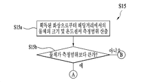
이 후, 스마트 디바이스(100)는 측정된 거리에서 제 1 센서(143a)의 측정범위(B)가 물체(O)내에 위치하는지를 검출할 수 있다(S15). Thereafter, the
앞서 도 4를 참조하여 설명된 바와 같이, 비 접촉식 제 1 센서(143a)의 측정범위(B)는 측정각(α)으로 인해 거리에 따라 변화될 수 있다. 또한, 이러한 변화되는 측정범위(B)로 인해, 도 11에 도시된 바와 같이, 거리에 따라 물체(O)의 크기에 대한 측정범위(B)의 상대적인 크기도 변화될 수 있으며, 이러한 상대적인 크기가 온도측정의 정확도를 결정할 수 있다. 보다 상세하게는, 도 11에서 물체(O)가 거리(L1)에 위치되면, 측정범위(B)는 직경(D1)의 크기를 가지며, 도 12(a)에도 도시되는 바와 같이, 이러한 크기는 물체(O)의 크기보다 작을 수 있다. 또한, 물체(O)가 거리(L2)에 위치되면, 측정범위(B)는 직경(D2)의 크기를 가지며, 도 12(b)에 도시되는 바와 같이, 이러한 크기는 대체적으로 온도가 측정될 물체(O)의 일부의 크기와 같을 수 있다. 이러한 두가지 경우들에 있어서, 즉 측정범위(B)가 물체(O)가 보다 작거나 대체적으로 같은 경우, 제 1 센서(143a)는 물체(O)의 온도만을 측정하게 되므로, 정확한 온도측정이 수행될 수 있다. 그러나, 도 11에서 물체(O)가 거리(L3)에 위치되면, 측정범위(B)는 직경(D3)의 크기를 가지며, 도 12(c)에 도시되는 바와 같이, 이러한 측정범위(B)의 크기는 온도가 측정될 물체(O) 또는 이의 일부의 크기보다 클 수 있다. 이러한 경우, 제 1 센서(143a)는 물체(O)의 온도 뿐만 아니라 물체(O)의 주변부의 온도도 함께 측정하므로, 측정된 온도는 부정확할 수 있다. As described above with reference to Fig. 4, the measurement range B of the non-contact
따라서, 물체(O)가 제 1 센서(143a)에 가깝게 위치되면, 측정범위(B)의 크기는 물체(O)의 크기와 대체적으로 같거나 상기 크기보다 상대적으로 작은 크기를 가질 수 있으며, 정확한 측정이 수행될 수 있다. 반면, 물체(O)가 제 1 센서(143a)에 멀게 위치되면, 측정범위(B)의 크기는 물체(O)의 크기보다 상대적으로 큰 크기를 가질 수 있으며, 측정이 부정확해질 수 있다. 이러한 상호관계를 고려할 때, 측정범위(B)가 물체(O)의 크기보다 같거나 작으면, 측정범위(B)가 물체(O)내에 전체적으로 배치될 수 있다. 따라서, 제 1 센서(143a)는 물체(O)만의 온도를 측정할 수 있으므로, 측정된 결과가 정확해질 수 있다. 보다 상세하게는, 정확한 측정을 위해 측정범위(B)는 인식된 물체(O)의 윤곽내에 전체적으로 배치될 필요가 있다. 즉, 측정범위(B)는 다른 물체들을 커버하지 않고 오직 상기 물체(O)만을 커버할 수 있으며, 이에 따라 정확한 측정이 수행될 수 있다. Accordingly, when the object O is located close to the
이와 같은 이유들을 고려하여, 본원의 제어방법(S20)에서 디바이스(100)는 검출단계(S15)에 따라, 정확한 측정을 위해 측정범위(B)가 물체(O)내에 배치되는지를 실제적인 측정에 앞서 검출할 수 있다. 이러한 검출단계(S15)에서, 도 10에 도시된 바와 같이, 먼저 스마트 디바이스(100)는 획득된 화상으로부터 측정된 거리에서의 물체(O)의 크기 및 측정범위(B)를 산출할 수 있다(S15a). 이미 앞서 설명된 바와 같이, 이러한 물체(O) 및 측정범위(B), 상세하게는 이의 크기의 산출은 인식단계(S12) 및 표시단계(S14)에서 수행될 수 있다. 그러나, 상기 검출단계(S15)이전에 스마트 디바이스(100)과 물체(O)사이의 거리가 변경될 수도 있으며, 이에 따라 물체(O) 및 측정범위(B)의 크기도 변화될 수도 있다. 따라서, 보다 정확한 측정을 위해, 상기 검출단계(S15)에서 최종적으로 상기 산출단계(S15a)가 수행될 수 있다. 또한, 물체(O) 및 측정범위(B)의 크기산출은 인식단계(S12) 및 표시단계(S14)에서만 또는 산출단계(S15a)에서만 수행될 수도 있다. 더 나아가, 이미 인식단계(S12 및 표시단계(S14)에서 설명되었으므로, 상기 산출단계(S15a)에 대한 상세한 설명은 생략된다. In consideration of these reasons, in the control method S20 of the present application, the
이후, 스마트 디바이스(100)는 산출된 물체(O)의 크기를 산출된 측정범위(B)와 비교할 수 있다(S15b). Thereafter, the
만일 물체(O)의 크기가 측정범위(B)보다 크면, 즉 측정범위(B)가 물체(O)의 크기보다 작으면, 스마트 디바이스(100)는 온도측정이 정확하게 수행되도록 측정범위(B)가 물체(B)내에 배치된다고 판단할 수 있다. 마찬가지로, 물체(O)의 크기가 측정범위(B)의 크기와 대체적으로 일치하는 경우에도, 온도측정이 비교적 정확하게 이루어질 수 있으며, 이에 따라 측정범위(B)가 물체(B)내에 배치된다고 판단될 수 있다. 따라서, 도 9 및 도 10에서 "A"로 연결된 바와 같이, 스마트 디바이스(100)는 제 1 센서(143a)를 이용하여 물체(O)의 온도를 측정할 수 있다(S16). 예를 들어, 도 13(d)에 도시된 바와 같이, 만일 측정범위(B)가 물체(B)보다 작으면, 물체(B)내에 전체적으로 배치될 수 있다. 이러한 경우, 디바이스(100)는 물체(O)의 온도를 측정할 수 있으며, 측정이 정상적으로 시작되었다는 것이 사용자에게 통지될 수 있다. 이러한 알림(M5)은 도 13(d)에 도시된 바와 같이, 텍스트로 디스플레이부(151)에 표시될 수 있으며, 진동이나 소리로서 사용자에게 전달될 수도 있다. 또한, 온도측정이 완료되면, 스마트 디바이스(100)는 측정된 온도를 사용자에게 통지할 수 있다. 예를 들어 도 13(d)에 도시된 바와 같이, 측정된 온도(M6)가 디스플레이부(151)에 표시될 수 있다. 또한, 측정된 온도(M6)는 음성으로도 사용자에게 전달될 수 있다. 더 나아가, 만일 사람의 체온이 측정된 경우, 스마트 디바이스(100)는 측정된 온도에 기초하여 건강상태를 제공할 수도 있다. 예를 들어, 도 13(e)에 도시된 바와 같이, 스마트 디바이스(100)는 건강상태로서 측정된 체온이 정상체온인지 여부를 사용자에게 알려줄 수 있다. 이러한 알림은 텍스트(M7)로 이루어질 수 있으며, 사용자가 보다 확인하기에 용이한 다이어그램(M8)으로 이루어질 수도 있다. If the size of the object O is larger than the measurement range B, i.e., if the measurement range B is smaller than the size of the object O, the
한편, 물체(O)의 크기가 측정범위(B)보다 작으면, 즉 측정범위(B)가 물체(O)의 크기보다 크면, 스마트 디바이스(100)는 측정범위(B)가 물체(B)내에 배치되지 않으며 정확한 측정이 수행될 수 없다고 판단할 수 있다. 따라서, 도 9 및 도 10에서 "B"로 연결된 바와 같이, 스마트 디바이스(100)는 물체(O)의 온도를 측정할 수 없음을 사용자에게 통지할 수 있다(S17). 예를 들어, 도 13(b)에 도시된 바와 같이, 만일 측정범위(B)가 물체(O)보다 크면, 이러한 측정범위(B)는 물체(B)내에 전체적으로 배치될 수 없다. 이러한 경우, 디바이스(100)는 물체(O)의 온도를 정확하게 측정할 수 없다고 판단할 수 있으며, 측정이 정상적으로 시작될 수 없음을 사용자에게 통지할 수 있다. 이러한 알림(M2)은 도 13(b)에 도시된 바와 같이, 텍스트로 디스플레이부(151)에 표시될 수 있으며, 진동이나 소리로서 사용자에게 전달될 수도 있다. 또한, 사용자에게 현 측정범위(B)가 부적절하며, 온도 측정이 시작될 수 없음을 알려주기 위해 측정범위(B)의 색상도 특정색상, 예를 들어 붉은 색으로 변경될 수 있다. On the other hand, if the size of the object O is smaller than the measurement range B, that is, if the measurement range B is larger than the size of the object O, the
이 후, 스마트 디바이스(100)는 측정범위(O)를 물체(O)내에 배치시키도록 사용자를 안내할 수 있다(S18). 거리에 따라 상기 측정범위(B)가 변화되므로, 스마트 디바이스(100), 즉 제 1 센서(143a)과 물체(O)사이의 거리를 조절함으로써 물체(O)에 대한 측정범위(B)의 상대적인 크기도 조절될 수 있다. 앞서 설명된 바와 같이, 스마트 디바이스(100)가 물체(O)에 가까워지면, 측정범위(B)는 물체(O)내에 배치될 정도로 축소될 수 있다. 따라서, 안내단계(S18)는 스마트 디바이스(100)와 물체(O)사이의 거리를 감소시킬 것을 사용자에에 알려줄 수 있다. 보다 상세하게는, 안내단계(S18)에서 스마트 디바이스(100)는 사용자가 스마트 디바이스(100)와 함께 물체(O)에 다가서거나 물체(O)를 사용자근처로 가져올 것을 안내할 수 있다. 이와 같은 알림(M4)은 도 13(c)에 도시된 바와 같이, 디스플레이부(151)에 표시되는 텍스트로 이루어질 수 있으며, 음성으로 사용자에게 직접 전달될 수 있다. 상기 안내에 따라 상기 거리가 조절됨으로써 측정범위(B)가 물체(O)보다 작아지면, 스마트 디바이스(100)는 정확한 측정을 위해 측정범위(B)가 물체(O)내에 배치된 것으로 판단할 수 있다(S15,S15b). 예를 들어, 적절한 측정범위(B)가 형성된 것을 알려주기 위해, 도 13(d)에 도시된 바와 같이, 측정범위(B)의 색상도 특정색상, 예를 들어 붉은 색으로부터 다른 색상, 예를 들어 파란색으로 변경될 수 있다. 이 후, 앞서 설명된 바와 같은, 측정단계(S16) 및 다른 단계들이 온도의 정확한 측정 및 이의 통지를 위해 순차적으로 수행될 수 있다. Thereafter, the
도 2 및 도 3를 참조하여 설명된 바와 같이, 스마트 디바이스(100)는 후방부에 배치된 제 1 센서(143a)에 추가적으로 전방부에 배치된 제 2 센서(143b)를 포함할 수 있다. 스마트 디바이스(100)의 전방부는 통화시에 사용자의 얼굴에 직접 접촉할 수 있다. 따라서, 제 2 센서(143b)는 접촉식 센서로 이루어지는 경우, 스마트 디바이스(100)에 접촉하는 물체, 특히 신체의 온도를 용이하게 측정할 수 있다. 이러한 이유로, 도 14에 따른 제어방법(S20)은 사용중 발생되는 스마트 디바이스(100)와 소정 물체사이 접촉을 이용하여 상기 물체의 온도를 측정하는 단계들을 포함할 수 있다. As described with reference to FIGS. 2 and 3, the
도 14는 본 출원에서 설명되는 스마트 디바이스의 추가적인 제어방법을 보여주는 순서도이다. 또한, 도 15는 도 14의 설정단계의 일 예를 보여주는 평면도이며, 도 16은 도 14의 검출단계의 일 예를 보여주는 평면도이다. 이들 도면들을 참조하여, 제어방법(S20)이 다음에서 상세하게 설명된다. 앞서 설명된 바와 같이, 제어방법(S20)은 신체, 즉 사용자의 온도 측정을 위해 구성되므로, 다음에서 사용자가 디바이스(100)에 의해 온도가 측정되는 물체(O)로서 설명된다. 14 is a flow chart illustrating an additional control method of the smart device described in the present application. FIG. 15 is a plan view showing an example of the setting step of FIG. 14, and FIG. 16 is a plan view showing an example of the detecting step of FIG. Referring to these figures, the control method S20 will be described in detail below. As described above, since the control method S20 is configured for temperature measurement of the body, i.e., the user, the following is described as the object O in which the temperature is measured by the
먼저 도 14를 참조하면, 제어방법(S20)에 있어서, 먼저 스마트 디바이스(100)는 통화중에 사용자의 체온을 측정하도록 설정될 수 있다(S21). 사용자(O)는 스마트 디바이스(100)의 전화 기능을 가장 빈번하게 사용하는 것이 일반적이다. 또한, 전화를 하는 동안 리시버(152a) 및 마이크(122)를 이용하기 위해 도 16에 도시된 바와 같이, 사용자는 디바이스(100)를 자신의 얼굴에 부착시킬 수 있으므로, 자연스럽게 접촉된 부위로부터 사용자의 온도가 측정될 수 있다. 이러한 이유로, 스마트 디바이스(100)가 다른 여러가지 경우들 중에서 통화시에 온도를 측정하는 것이 용이하고 정확한 측정에 있어서 유리할 수 있다. 그러나, 통화는 빈번하게 이루어지므로, 통화할 때마다 체온이 측정되는 것은 사용자는 불편하게 할 수 있다. 따라서, 디바이스(100)는 통화중의 온도측정을 선택적으로 수행할 있도록 구성되는 것이 필요할 수 있으며, 이러한 선택적 수행을 위해 상기 설정단계(S21)가 포함될 수 있다. 보다 상세하게는, 도 15의 예에 나타나는 바와 같이, 스마트 디바이스(100)는 디스플레이부(151)에 체온 측정을 위한 메뉴(M9)를 제공할 수 있다. 이러한 메뉴(M9)는 통화중에 체온측정을 가능하게 하는 옵션을 포함할 수 있다. 이러한 옵션을 선택함으로써 통화중에 체온 측정이 자동적으로 이루어 질 수 있으며, 사용자는 온도측정에 추가적인 조작을 요구받지 않으므로 편리할 수 있다. 다른 한편, 메뉴(M9)는 수동으로 체온측정을 가능하게 하는 옵션을 포함할 수 있다. 이러한 옵션이 선택되면, 스마트 디바이스(100)는 사용자와 상기 디바이스(100)사이에 접촉이 발생되는 경우, 예를 들어 통화가 개시되면, 사용자에게 온도측정이 가능하다는 알림을 제공할 수 있다. 이러한 알림은 음성 또는 진동등으로 이루어질 수 있다. 따라서, 사용자는 수동으로 접촉중, 예를 들어 통화중에 스마트 디바이스(100)에 자신의 체온을 측정할 것을 지시할 수 있다. 이러한 지시는 사용자가 스마트 디바이스(100)에 설치된 사용자 입력부(123), 예를 들어 스마트 디바이스(100)에 제공되는 물리적 버튼들을 접촉 또는 통화중에 누름으로써 상기 디바이스(100)에 주어질 수 있다. Referring first to FIG. 14, in a control method (S20), the
상기 설정단계(S21)에서 자동적인 측정이 설정되는 경우, 스마트 디바이스(100)는 전화가 걸려오는지를 검출할 수 있다(S22). 상기 검출단계(S22)에서 스마트 디바이스(100)는 외부 네트워크로부터 자신에게 전달되는 다양한 신호들을 분석하고 이러한 분석으로부터 전화가 걸려왔는지를 검출할 수 있다. 예를 들어, 전화는 일반적인 무선통신신호 뿐만 아니라 VoIP와 같은 무선 인터넷 신호룰 이용할 수도 있으며, 디바이스(100)는 이러한 신호들이 수신되면 전화가 온 것을 판단할 수 있다. If the automatic measurement is set in the setting step S21, the
만일 전화가 실제적으로 걸려온 경우, 스마트 디바이스(100)는 사용자(O)의 신체가 제 2 온도센서(134b)와 접촉되었는지를 검출할 수 있다(S23). 도 16에 도시된 바와 같이, 통화중에, 일반적으로 사용자(O)는 통화음을 잘 듣기 위해서 리시버(143b)를 자신의 귀에 밀착시키는 경향이 있다. 즉, 대부분의 경우, 리스버(143b) 및 이의 주변영역은 통화중에 사용자(O)와 직접적으로 접촉할 수 있다. 또한, 귀는 일반적으로 신체의 온도를 잘 반영하는 기관일 수 있다. 따라서, 도 2에 도시된 바와 같이, 제 2 온도센서(134b)는 사용자(O), 즉 이의 귀와 잘 접촉할 수 있도록 리시버(152a)에 인접하게 배치될 수 있다. 또한, 스마트 디바이스(100)는 전면에 부착된 근접센서(141)을 이용하여 사용자(O)와 디바이스(100)사이의 거리를 측정할 수 있다. 따라서, 측정된 거리가 "0" 또는 "0"에 가까우면, 즉 실질적인 거리가 측정되지 않으면, 스마트 디바이스(100)은 사용자(O)와 상기 디바이스(100), 즉 제 2 센서(143b)가 접촉한 것으로 판단할 수 있다. 다른 한편, 측정된 거리가 실질적인 크기를 가지면, 스마트 디바이스(100)은 사용자(O)와 제 2 센서(143b)가 접촉하지 않은 것으로 판단할 수 있다. If a phone call is actually made, the
만일 사용자(O)의 신체가 제 2 센서(143b)와 접촉되어 있다고 판단되는 경우, 스마트 디바이스(100)는 제 2 센서(143b)를 이용하여 사용자(O)의 온도를 측정할 수 있다(S24). 온도측정이 완료되면, 스마트 디바이스(100)는 측정된 온도를 사용자에게 통지할 수 있다. 예를 들어, 측정된 온도가 디스플레이부(151)에 표시될 수 있으며, 측정된 온도가 음성으로도 사용자에게 전달될 수 있다. 더 나아가, 앞서 도 13(e)를 참조하여 설명된 바와 같이, 스마트 디바이스(100)는 건강상태로서 측정된 체온이 정상체온인지 여부를 사용자에게 알려줄 수 있다. 이러한 알림은 문자으로 이루어질 수 있으며, 사용자가 보다 확인하기에 용이한 다이어그램으로 이루어질 수도 있다. If it is determined that the body of the user O is in contact with the second sensor 143b, the
한편, 사용자(O)의 신체가 제 2 센서(143b)와 접촉되지 않는다고 판단되는 경우, 스마트 디바이스(100)는 사용자(O)의 온도를 측정할 수 없음을 사용자에게 통지할 수 있다(S25). 예를 들어, 이러한 알림은 도 13(b)에서도 도시된 바와 같이, 텍스트로 디스플레이부(151)에 표시될 수 있으며, 진동이나 소리로서 사용자에게 전달될 수도 있다. On the other hand, when it is determined that the body of the user O is not in contact with the second sensor 143b, the
이 후, 스마트 디바이스(100)는 상기 사용자(O)의 신체를 제 2 센서(143b)와 접촉시키도록 사용자를 안내할 수 있다(S25). 예를 들어, 안내단계(S25)에서, 스마트 디바이스(100)는 신체와 제 2 센서(143b)의 접촉을 위해 상기 디바이스(100)를 사용자의 얼굴, 보다 상세하게는 귀에 밀착시킬 것을 사용자에게 알려줄 수 있다. 이와 같은 알림은 음성이나 진동으로 사용자에게 직접 전달될 수 있다. 상기 안내에 따라 스마트 디바이스(100)가 귀에 밀착되고 상기 디바이스(100)와 사용자(O)사이의 거리가 "0"이 되거나 "0"에 가까워지면, 스마트 디바이스(100)는 정확한 측정을 위해 사용자(O)의 신체가 제 2 센서(143b)와 접촉한 것으로 판단할 수 있다(S23). 이 후, 앞서 설명된 바와 같은, 측정단계(S24) 및 다른 단계들이 온도의 정확한 측정 및 이의 통지를 위해 순차적으로 수행될 수 있다. 한편, 소정시간이 경과할 때까지, 사용자(O)의 신체와 제 2 센서(143b)가 접촉한 것으로 판단되지 않으면, 사용자의 체온 측정은 자동적으로 종료될 수 있다(S26). Thereafter, the
한편, 온도센서(143:143a,143b)은 신체 이외의 다른 물체의 온도도 함께 측정할 수 있으므로, 측정된 온도에 기초하여 스마트 디바이스(100)는 다양한 기능을 사용자에게 제공할 수 있다. 이와 같은 다양한 기능들 중에서 온도센서(143)을 음식의 요리에 활용하는 제어방법이 하나의 예로써 다음에서 설명된다. 도 17은 본 출원에서 설명되는 스마트 디바이스의 추가적인 제어방법을 보여주는 순서도이며, 도 18은 도 17에 따른 제어방법의 일 예를 보여주는 평면도이다. On the other hand, the temperature sensor 143 (143a, 143b) can measure the temperature of an object other than the body together, so that the
일반적으로 사용자는 자신의 원하는 요리를 먼저 정하고, 정해진 요리에 요구되는 식자재(ingeredient)를 준비하게 된다. 반면, 이미 가지고 있는 식자재에 기초하여 사용자는 요리를 결정할 수도 있다. 이러한 경우 둘 다에 있어서, 요리법에 대해 안내를 받는 것은 적절한 요리에 도움이 될 수 있다. 그러나, 요리법의 안내를 위해서는 먼저 사용자가 무슨 식자재를 가지고 있는지가 중요할 수 있다. 따라서, 도 17에 따른 제어방법(S30)에 있어서, 먼저 스마트 디바이스(100)는 식자재의 화상을 획득하고 획득된 화상으로부터 식자재의 종류를 인식할 수 있다(S31,S32).보다 상세하게는, 도 18(a)에 도시된 바와 같이, 식자재로서 사용자가 새우를 가지고 있는 경우, 스마트 디바이스(100)는 제 2 카메라(121b)를 이용하여 식자재의 화상을 획득하고 획득된 화상에 대한 분석을 통해 식자재의 종류를 검출할 수 있다. Generally, the user sets his / her desired dish first and prepares the ingeredient required for the predetermined dish. On the other hand, the user may decide the cooking based on the food materials already possessed. In both of these cases, being informed about recipes can be helpful in proper cooking. However, it can be important for the user to know what kind of food ingredients he / she has in order to guide the recipes. 17, the
식자재의 종류가 인식되면, 스마트 디비아스(100)는 인식된 식자재를 이용하는 요리법을 제공할 수 있다(S33). 도 18(a)에 도시된 바와 같이, 스마트 디바이스(100)는 인터넷을 통한 검색 또는 자신의 기 저장하고 있는 데이터의 검색에 의해 인식된 식자재에 관련된 다수개의 요리법들의 리스트를 포함하는 메뉴(M10)을 사용자에게 디스플레이부(151)를 통해 사용자에게 제공할 수 있다. 사용자가 어느 하나의 요리법을 선택하면, 도 18(b)에 도시된 바와 같이 스마트 디바이스(100)는 선택된 요리법에 대한 상세한 내용을 사용자에게 제공할 수 있다. 만일 사용자가 미리 요리를 정한 경우에, 사용자는 제공된 옵션(M10)으로부터 더 낳은 요리법을 제공받을 수 있다. 또한, 사용자가 요리를 정하지 못한 경우에도 사용자는 제공된 옵션(M10)으로부터 자신이 원하는 요리 및 이의 요리법을 결정할 수 있다. Once the type of the food material is recognized, the
이 후, 사용자는 선택한 요리법에 따라 요리를 할 수 있다. 일반적으로 요리법들은 식재재와 관련된 다양한 프로세스들을 수반하며, 이러한 프로세스들에서 정확한 온도를 유지하는 것이 중요할 수 있다. 따라서, 스마트 디바이스(100)는 식자재를 요리하는 동안 상기 식자재를 요리하는 온도를 측정할 수 있다(S34). 예를 들어, 도 18(c)에 도시된 바와 같이, 사용자가 새우 튀김을 만들기로 결정한 경우, 스마트 디바이스(100)는 제 1 센서(143a)를 이용하여 원격으로 기름의 온도를 측정하고 이를 사용자에게 알려줄 수도 있다. 만일 필요한 경우, 비록 도시되지는 않았으나, 제 2 센서(143b)를 식자재에 접촉시켜 온도가 측정될 수도 있다. 또한, 스마트 디바이스(100)는 온도 측정과 관련하여 부가적인 기능도 사용자게에 제공할 수도 있다. 예를 들어, 도 18(c)에 도시된 바와 같이, 스마트 디바이스(100)는 안내된 요리법에 따른 최적의 온도에 도달할 때까지의 시간을 예측하고 이를 사용자에게 알려줄 수도 있다. 또한, 이러한 시간을 사용자가 정확하게 파악할 수 있도록고 타이머(M11)를 사용자에게 제공할 수도 있다. After this, the user can cook according to the selected recipe. Generally, recipes involve a variety of processes involving plant material, and it may be important to maintain accurate temperatures in these processes. Thus, the
또한, 측정된 온도에 기초하여 스마트 디바이스(100)는 식재료를 요리하는 과정들을 미리 안내할 수도 있다(S35), 앞서 설명된 바와 같이, 스마트 디바이스(100)는 선택된 요리법에 대한 정보를 가지고 있으므로, 상기 요리법을 참조하여 측정된 온도에서 수행되어야 하는 프로세스들을 사용자에게 미리 알려줄 수도 있다. 예를 들어, 도 18(d)에 도시된 바와 같이, 스마트 디바이스(100)는 최적의 온도인 180℃에서 새우가 기름에 넣어져야 한다는 것을 사용자에게 미리 알려줄 수 있으며, 이에 따라 사용자는 미리 새우를 준비할 수 있다. 이후, 최적의 온도에 도달하면, 스마트 디바이스(100)는 측정된 최적의 온도를 사용자에게 통보할 수 있다(S36). 예를 들어, 도 18(d)에 도시된 바와 같이, 스마트 디바이스(100)는 기름이 최적의 온도인 180℃로 가열되었음을 사용자에게 알려줄 수 있다. 동시에, 상기 안내단계(S35)와 유사하게, 상기 최적의 온도에서 수행되어야 하는 과정, 즉 새우의 투입도 사용자에게 다시 한번 안내될 수 있다. In addition, based on the measured temperature, the
상기의 상세한 설명은 모든 면에서 제한적으로 해석되어서는 아니되고 예시적인 것으로 고려되어야 한다. 본 발명의 범위는 첨부된 청구항의 합리적 해석에 의해 결정되어야 하고, 본 발명의 등가적 범위 내에서의 모든 변경은 본 발명의 범위에 포함된다.The foregoing detailed description should not be construed in all aspects as limiting and should be considered illustrative. The scope of the present invention should be determined by rational interpretation of the appended claims, and all changes within the scope of equivalents of the present invention are included in the scope of the present invention.
100: 스마트 디바이스
140: 센싱부
143: 온도센서
143a: 제 1 센서
143b: 제 2 센성100: smart device 140: sensing unit
143:
143b: second sense
Claims (21)
상기 물체의 온도측정을 위해 상기 스마트 디바이스로부터 상기 물체까지의 거리를 측정하는 단계;
상기 측정된 거리에서의 상기 온도센서의 측정범위가 상기 물체내에 배치되지 않으면, 상기 물체의 온도를 측정할 수 없음을 사용자에게 통지하는 단계; 및
상기 측정범위를 상기 물체내에 배치시키도록 사용자를 안내하는 단계를 포함하는 스마트 디바이스의 제어방법. A smart device comprising a temperature sensor measuring a temperature of an object at a position spaced apart from a predetermined object and having a measuring range that varies according to a distance to the object,
Measuring a distance from the smart device to the object for temperature measurement of the object;
Notifying a user that the temperature of the object can not be measured unless the measurement range of the temperature sensor at the measured distance is disposed within the object; And
And guiding the user to place the measurement range within the object.
상기 온도센서의 측정범위는 이의 온도가 상기 온도센서에 의해 측정될 수 있는 면적인 것을 특징으로 하는 스마트 디바이스의 제어방법.The method according to claim 1,
Wherein the measurement range of the temperature sensor is an area whose temperature can be measured by the temperature sensor.
상기 측정단계 이전에 상기 스마트 디바이스에서 상기 물체의 화상을 획득하는 단계; 및;
상기 스마트 디바이스에서 상기 획득된 화상으로부터 상기 물체를 인식하는 단계를 더 포함하는 것을 특징으로 하는 스마트 디바이스의 제어방법. The method according to claim 1,
Obtaining an image of the object at the smart device prior to the measuring step; And;
Further comprising the step of recognizing the object from the acquired image in the smart device.
상기 인식단계는:
상기 획득된 화상에서 중앙에 위치하거나 가장 큰 물체를 자동적으로 인식하는 단계; 또는
상기 사용자에 의해 지정된 물체를 인식하는 단계를 포함하는 것을 특징으로 하는 스마트 디바이스의 제어방법. The method of claim 3,
Wherein the recognizing step comprises:
Automatically recognizing the center or the largest object in the obtained image; or
And recognizing an object designated by the user.
상기 인식단계는 상기 획득된 화상으로부터 사람의 신체를 자동적으로 인식하는 단계로 이루어지는 것을 특징으로 하는 스마트 디바이스의 제어방법. The method of claim 3,
Wherein the recognizing step comprises automatically recognizing a person's body from the obtained image.
상기 측정단계는 상기 인식단계에서 인식된 물체와 상기 스마트 디바이스 사이의 거리를 측정하는 단계로 이루어지는 것을 특징으로 하는 스마트 디바이스의 제어방법. The method of claim 3,
Wherein the measuring step comprises measuring a distance between the smart device and the object recognized in the recognizing step.
상기 통지단계에 이전에, 상기 측정된 거리에서의 상기 온도센서의 측정범위를 디스플레이하는 단계를 더 포함하는 것을 특징으로 하는 스마트 디바이스의 제어방법. The method according to claim 1,
Further comprising displaying the measurement range of the temperature sensor at the measured distance prior to the notification step.
상기 통지단계에 이전에, 상기 측정된 거리에서 상기 온도센서의 측정범위가 상기 물체내에 위치하는지를 검출하는 단계를 더 포함하는 것을 특징으로 하는 스마트 디바이스의 제어방법. The method according to claim 1,
Further comprising, prior to said notifying step, detecting whether a measurement range of said temperature sensor is located within said object at said measured distance.
상기 검출단계는:
상기 스마트 디바이스에서 획득된 화상으로부터 상기 거리에서의 상기 물체의 크기 및 상기 온도 센서의 측정범위를 산출하는 단계; 및
상기 검출된 물체의 크기를 상기 산출된 온도센서의 측정범위와 비교하는 단계를 포함하는 것을 특징으로 하는 스마트 디바이스의 제어방법.9. The method of claim 8,
Wherein the detecting step comprises:
Calculating a size of the object at the distance and a measurement range of the temperature sensor from the image obtained at the smart device; And
And comparing the size of the detected object with the measured range of the calculated temperature sensor.
상기 검출단계는: 상기 물체의 크기가 상기 온도센서의 측정범위보다 크면, 상기 온도센서의 측정범위가 상기 물체내에 배치된다고 판단하는 단계; 및 상기 물체의 크기가 상기 온도 센서의 측정범위보다 작으면, 상기 온도센서의 측정범위가 상기 물체내에 배치되지 않는다고 판단하는 단계를 포함하는 것을 특징으로 하는 스마트 디바이스의 제어방법. 10. The method of claim 9,
Determining that a measurement range of the temperature sensor is disposed within the object if the size of the object is greater than the measurement range of the temperature sensor; And determining that the measurement range of the temperature sensor is not disposed within the object if the size of the object is smaller than the measurement range of the temperature sensor.
상기 안내단계는 상기 스마트 디바이스와 상기 물체사이의 거리를 감소시킬 것을 사용자에게 알려주는 단계로 이루어지는 것을 특징으로 하는 스마트 디바이스의 제어방법. The method according to claim 1,
Wherein the step of informing comprises informing the user that the distance between the smart device and the object is to be reduced.
상기 측정된 거리에서 상기 온도센서의 측정범위가 상기 물체내에 포함되면, 상기 온도센서를 이용하여 상기 물체의 온도를 바로 측정하는 단계; 및 측정된 온도를 사용자에게 통지하는 단계를 더 포함하는 것을 특징으로 하는 스마트 디바이스의 제어방법. The method according to claim 1,
Directly measuring the temperature of the object using the temperature sensor if the measured range of the temperature sensor is within the object at the measured distance; And notifying the user of the measured temperature.
상기 스마트 디바이스의 카메라의 화각과 상기 온도센서의 측정각이 서로 겹쳐지도록 상기 온도센서와 상기 카메라가 구성되는 것을 특징으로 하는 스마트 디바이스의 제어방법. The method according to claim 1,
Wherein the temperature sensor and the camera are configured such that an angle of view of a camera of the smart device and a measurement angle of the temperature sensor are overlapped with each other.
상기 카메라의 화각은 80°이며, 상기 온도센서의 측정각은 45°인 것을 특징으로 하는 스마트 디바이스의 제어방법. 14. The method of claim 13,
Wherein the angle of view of the camera is 80 ° and the angle of the temperature sensor is 45 °.
상기 온도센서는 상기 카메라로부터 반경 8mm내에 배치되는 것을 특징으로 하는 스마트 디바이스의 제어방법. 14. The method of claim 13,
Wherein the temperature sensor is disposed within a radius of 8 mm from the camera.
상기 스마트 디바이스에 전화가 걸려오는지를 검출하는 단계;
상기 전화가 걸려온 경우, 사용자의 신체가 상기 온도센서와 접촉되었는지를 검출하는 단계; 및
상기 사용자의 신체가 상기 온도센서와 접촉되어있는 경우, 상기 사용자의 체온을 측정하는 단계로 이루어지는 스마트 디바이스의 제어방법. A smart device comprising a temperature sensor configured to measure a temperature of an object by contacting the object,
Detecting whether a call is made to the smart device;
Detecting whether the user's body is in contact with the temperature sensor when the telephone call is received; And
And measuring the body temperature of the user when the body of the user is in contact with the temperature sensor.
상기 온도센서는 상기 스마트 디바이스에 설치되며 통화음을 상기 사용자에게 전달시키도록 구성되는 리시버에 인접하게 배치되는 것을 특징으로 하는 스마트 디바이스의 제어방법. 17. The method of claim 16,
Wherein the temperature sensor is disposed adjacent to a receiver that is installed in the smart device and is configured to communicate a call tone to the user.
상기 사용자의 신체가 상기 온도센서와 접촉되어 있지 않으면, 상기 물체의 온도를 측정할 수 없음을 사용자에게 통지하는 단계를 더 포함하는 것을 특징으로 하는 스마트 디바이스의 제어방법. 17. The method of claim 16,
Further comprising the step of notifying the user that the temperature of the object can not be measured if the body of the user is not in contact with the temperature sensor.
상기 사용자의 신체가 상기 온도센서와 접촉되어 있지 않으면, 상기 사용자의 신체를 상기 온도센서와 접촉시키도록 상기 사용자를 안내하는 단계를 더 포함하는 스마트 디바이스의 제어방법. 17. The method of claim 16,
And guiding the user to contact the body of the user with the temperature sensor if the user's body is not in contact with the temperature sensor.
상기 전화가 걸려오는지를 검출하는 단계이전에, 상기 전화가 걸려올 때 상기 사용자의 체온을 자동적으로 측정하도록 설정하는 단계를 더 포함하는 것을 특징으로 하는 스마트 디바이스의 제어방법. 17. The method of claim 16,
Further comprising the step of automatically setting the user's body temperature to be measured when the telephone is received, prior to the step of detecting whether the telephone call is received.
만일 소정시간동안 상기 사용자가 상기 온도센서와 접촉되지 않으면, 상기 사용자의 체온 측정을 종료하는 단계를 더 포함하는 것을 특징으로 하는 스마트 디바이스의 제어방법. 17. The method of claim 16,
And terminating the temperature measurement of the user if the user is not in contact with the temperature sensor for a predetermined period of time.
Priority Applications (3)
| Application Number | Priority Date | Filing Date | Title |
|---|---|---|---|
| KR1020150153133A KR20170050954A (en) | 2015-11-02 | 2015-11-02 | Smart device and method for contolling the same |
| PCT/KR2015/012485 WO2017078208A1 (en) | 2015-11-02 | 2015-11-19 | Smart device and method for controlling same |
| US15/772,519 US10739202B2 (en) | 2015-11-02 | 2015-11-19 | Smart device and method for controlling same |
Applications Claiming Priority (1)
| Application Number | Priority Date | Filing Date | Title |
|---|---|---|---|
| KR1020150153133A KR20170050954A (en) | 2015-11-02 | 2015-11-02 | Smart device and method for contolling the same |
Publications (1)
| Publication Number | Publication Date |
|---|---|
| KR20170050954A true KR20170050954A (en) | 2017-05-11 |
Family
ID=58662179
Family Applications (1)
| Application Number | Title | Priority Date | Filing Date |
|---|---|---|---|
| KR1020150153133A KR20170050954A (en) | 2015-11-02 | 2015-11-02 | Smart device and method for contolling the same |
Country Status (3)
| Country | Link |
|---|---|
| US (1) | US10739202B2 (en) |
| KR (1) | KR20170050954A (en) |
| WO (1) | WO2017078208A1 (en) |
Cited By (1)
| Publication number | Priority date | Publication date | Assignee | Title |
|---|---|---|---|---|
| KR102320224B1 (en) * | 2020-12-11 | 2021-11-02 | 주식회사 웨이브온 | Apparatus for measuring body temperature in non-face-to-face and method |
Families Citing this family (29)
| Publication number | Priority date | Publication date | Assignee | Title |
|---|---|---|---|---|
| CN107219017A (en) * | 2017-05-26 | 2017-09-29 | 上海展扬通信技术有限公司 | Guard method, system and terminal |
| EP3450941B1 (en) * | 2017-08-31 | 2024-03-13 | AViTA Corporation | Temperature measuring device and measurement alignment method thereof |
| TWI797122B (en) * | 2018-04-25 | 2023-04-01 | 吳建州 | Control system and method for informationalized karaoke or multimedia system interfaces |
| CA3054216C (en) | 2018-09-05 | 2023-08-01 | Honeywell International Inc. | Methods and systems for improving infection control in a facility |
| WO2020085303A1 (en) * | 2018-10-22 | 2020-04-30 | パナソニックIpマネジメント株式会社 | Information processing device and information processing method |
| CN109528013B (en) * | 2018-12-15 | 2023-10-24 | 金华乐嘉厨具有限公司 | Pot capable of detecting temperature and capacity in pot |
| US10978199B2 (en) | 2019-01-11 | 2021-04-13 | Honeywell International Inc. | Methods and systems for improving infection control in a building |
| CN109616019B (en) * | 2019-01-18 | 2021-05-18 | 京东方科技集团股份有限公司 | Display panel, display device, three-dimensional display method and three-dimensional display system |
| US11537835B2 (en) * | 2019-05-22 | 2022-12-27 | Weavix, Inc. | Smart badge system and method |
| CN111412992A (en) * | 2020-04-03 | 2020-07-14 | 华为技术有限公司 | Method for measuring temperature and electronic equipment |
| TWI800732B (en) * | 2020-04-08 | 2023-05-01 | 開曼群島商粉迷科技股份有限公司 | Method and system for providing location-based personalized content |
| CN113589889A (en) * | 2020-04-30 | 2021-11-02 | 维沃移动通信有限公司 | Electronic device and control method thereof |
| KR20230017800A (en) * | 2020-06-01 | 2023-02-06 | 플리르 시스템스 에이비 | Elevated Temperature Screening Systems and Methods |
| US11620594B2 (en) | 2020-06-12 | 2023-04-04 | Honeywell International Inc. | Space utilization patterns for building optimization |
| US11914336B2 (en) | 2020-06-15 | 2024-02-27 | Honeywell International Inc. | Platform agnostic systems and methods for building management systems |
| US11625964B2 (en) | 2020-06-15 | 2023-04-11 | Honeywell International Inc. | Methods and systems for temperature screening using a mobile device |
| US11783658B2 (en) | 2020-06-15 | 2023-10-10 | Honeywell International Inc. | Methods and systems for maintaining a healthy building |
| US11783652B2 (en) | 2020-06-15 | 2023-10-10 | Honeywell International Inc. | Occupant health monitoring for buildings |
| US11184739B1 (en) | 2020-06-19 | 2021-11-23 | Honeywel International Inc. | Using smart occupancy detection and control in buildings to reduce disease transmission |
| US11823295B2 (en) | 2020-06-19 | 2023-11-21 | Honeywell International, Inc. | Systems and methods for reducing risk of pathogen exposure within a space |
| US11619414B2 (en) | 2020-07-07 | 2023-04-04 | Honeywell International Inc. | System to profile, measure, enable and monitor building air quality |
| CN113923323B (en) * | 2020-07-09 | 2023-01-31 | 维沃移动通信有限公司 | Electronic device, control method thereof and control device thereof |
| US11402113B2 (en) | 2020-08-04 | 2022-08-02 | Honeywell International Inc. | Methods and systems for evaluating energy conservation and guest satisfaction in hotels |
| US11894145B2 (en) | 2020-09-30 | 2024-02-06 | Honeywell International Inc. | Dashboard for tracking healthy building performance |
| JP6951805B1 (en) * | 2020-12-23 | 2021-10-20 | 日本精密測器株式会社 | thermometer |
| US11372383B1 (en) | 2021-02-26 | 2022-06-28 | Honeywell International Inc. | Healthy building dashboard facilitated by hierarchical model of building control assets |
| US11662115B2 (en) | 2021-02-26 | 2023-05-30 | Honeywell International Inc. | Hierarchy model builder for building a hierarchical model of control assets |
| US11842618B2 (en) | 2021-03-09 | 2023-12-12 | Weavix, Inc. | Confined space monitoring system and method |
| US11474489B1 (en) | 2021-03-29 | 2022-10-18 | Honeywell International Inc. | Methods and systems for improving building performance |
Family Cites Families (7)
| Publication number | Priority date | Publication date | Assignee | Title |
|---|---|---|---|---|
| KR20040061870A (en) | 2002-12-31 | 2004-07-07 | 주식회사 팬택앤큐리텔 | Infrared rays temperature measurement apparatus using the mobile terminal |
| KR101156203B1 (en) | 2005-12-01 | 2012-06-18 | 삼성전자주식회사 | Portable terminal with infrared sensor and method using it |
| CN102265125B (en) * | 2008-10-23 | 2015-09-30 | Kaz欧洲有限公司 | There is the contactless clinical thermometer of stray radiation shielding |
| KR101499081B1 (en) | 2012-06-20 | 2015-03-05 | 엘시스템 주식회사 | Thermal imaging camera module and smart phone |
| US20140159912A1 (en) * | 2012-12-10 | 2014-06-12 | Jacob Fraden | Biomedical monitor for smartphone |
| KR20150072957A (en) | 2013-12-20 | 2015-06-30 | 삼성전자주식회사 | Method for measuring posture, terminal thereof, and system thereof |
| KR102249824B1 (en) | 2014-02-24 | 2021-05-10 | 삼성전자주식회사 | Apparatus and Method for sensing body imformation thereof |
-
2015
- 2015-11-02 KR KR1020150153133A patent/KR20170050954A/en not_active Application Discontinuation
- 2015-11-19 WO PCT/KR2015/012485 patent/WO2017078208A1/en active Application Filing
- 2015-11-19 US US15/772,519 patent/US10739202B2/en active Active
Cited By (1)
| Publication number | Priority date | Publication date | Assignee | Title |
|---|---|---|---|---|
| KR102320224B1 (en) * | 2020-12-11 | 2021-11-02 | 주식회사 웨이브온 | Apparatus for measuring body temperature in non-face-to-face and method |
Also Published As
| Publication number | Publication date |
|---|---|
| US20180313695A1 (en) | 2018-11-01 |
| US10739202B2 (en) | 2020-08-11 |
| WO2017078208A1 (en) | 2017-05-11 |
Similar Documents
| Publication | Publication Date | Title |
|---|---|---|
| KR20170050954A (en) | Smart device and method for contolling the same | |
| KR101927323B1 (en) | Mobile terminal and method for controlling the same | |
| CN106361268B (en) | Mobile terminal and control method thereof | |
| KR20160066951A (en) | Mobile terminal and method for controlling the same | |
| KR20170128820A (en) | Mobile terminal and method for controlling the same | |
| KR20160015719A (en) | Mobile terminal and method for controlling the same | |
| KR20170137476A (en) | Mobile device and method for controlling thereof | |
| KR20180001358A (en) | Mobile terminal | |
| KR20160006515A (en) | Mobile terminal and control method for the mobile terminal | |
| KR20160016263A (en) | Mirror display device and operating method thereof | |
| KR20160041557A (en) | Mobile terminal and method for controlling the same | |
| KR20160113906A (en) | Mobile terminal and control method thereof | |
| KR20170010703A (en) | Mobile terminal and method of controlling the same | |
| KR20170114615A (en) | Mobile terminal and method of controlling the same | |
| KR20170136759A (en) | Home automation system and method for controlling the same | |
| KR20170004608A (en) | Smart device and method for contolling the same | |
| KR20170004160A (en) | Mobile terminal and method for controlling the same | |
| US10122448B2 (en) | Mobile terminal and control method therefor | |
| US20170235879A1 (en) | Mobile terminal and method for controlling the same | |
| KR20220047293A (en) | A mobile terminal for setting a home screen and a method for controlling the same | |
| KR20170068252A (en) | Mobile terminal and method for controlling the same | |
| KR20170006759A (en) | Mobile terminal and method for controlling the same | |
| KR101792516B1 (en) | Iot device, mobile terminal and method for controlling the iot device with vibration pairing | |
| KR20160086159A (en) | Mobile terminal and method for controlling the same | |
| US20220374145A1 (en) | Electronic device for outputting keyboard interface and control method therefor |
Legal Events
| Date | Code | Title | Description |
|---|---|---|---|
| WITB | Written withdrawal of application |