KR20170037431A - Mobile terminal and control method for the mobile terminal - Google Patents
Mobile terminal and control method for the mobile terminal Download PDFInfo
- Publication number
- KR20170037431A KR20170037431A KR1020150137047A KR20150137047A KR20170037431A KR 20170037431 A KR20170037431 A KR 20170037431A KR 1020150137047 A KR1020150137047 A KR 1020150137047A KR 20150137047 A KR20150137047 A KR 20150137047A KR 20170037431 A KR20170037431 A KR 20170037431A
- Authority
- KR
- South Korea
- Prior art keywords
- external electronic
- electronic device
- information
- screen
- output
- Prior art date
Links
Images


Classifications
-
- H04M1/72522—
-
- G—PHYSICS
- G06—COMPUTING; CALCULATING OR COUNTING
- G06F—ELECTRIC DIGITAL DATA PROCESSING
- G06F3/00—Input arrangements for transferring data to be processed into a form capable of being handled by the computer; Output arrangements for transferring data from processing unit to output unit, e.g. interface arrangements
- G06F3/01—Input arrangements or combined input and output arrangements for interaction between user and computer
- G06F3/048—Interaction techniques based on graphical user interfaces [GUI]
- G06F3/0487—Interaction techniques based on graphical user interfaces [GUI] using specific features provided by the input device, e.g. functions controlled by the rotation of a mouse with dual sensing arrangements, or of the nature of the input device, e.g. tap gestures based on pressure sensed by a digitiser
- G06F3/0488—Interaction techniques based on graphical user interfaces [GUI] using specific features provided by the input device, e.g. functions controlled by the rotation of a mouse with dual sensing arrangements, or of the nature of the input device, e.g. tap gestures based on pressure sensed by a digitiser using a touch-screen or digitiser, e.g. input of commands through traced gestures
-
- G—PHYSICS
- G06—COMPUTING; CALCULATING OR COUNTING
- G06F—ELECTRIC DIGITAL DATA PROCESSING
- G06F3/00—Input arrangements for transferring data to be processed into a form capable of being handled by the computer; Output arrangements for transferring data from processing unit to output unit, e.g. interface arrangements
- G06F3/14—Digital output to display device ; Cooperation and interconnection of the display device with other functional units
-
- H04M1/7253—
-
- H—ELECTRICITY
- H04—ELECTRIC COMMUNICATION TECHNIQUE
- H04M—TELEPHONIC COMMUNICATION
- H04M2250/00—Details of telephonic subscriber devices
- H04M2250/22—Details of telephonic subscriber devices including a touch pad, a touch sensor or a touch detector
Landscapes
- Engineering & Computer Science (AREA)
- Theoretical Computer Science (AREA)
- General Engineering & Computer Science (AREA)
- Human Computer Interaction (AREA)
- Physics & Mathematics (AREA)
- General Physics & Mathematics (AREA)
- Telephone Function (AREA)
- User Interface Of Digital Computer (AREA)
Abstract
Description
The present invention relates to a mobile terminal configured to perform communication with an external electronic device and a control method thereof.
The terminal is movable And may be divided into a mobile / portable terminal and a stationary terminal depending on whether the mobile terminal is a mobile terminal or a mobile terminal. The mobile terminal can be divided into a handheld terminal and a vehicle mount terminal according to whether the user can directly carry the mobile terminal.
As the functions of the terminal are diversified, the terminal is implemented in the form of a multimedia device having a combination of functions such as photographing and photographing of a moving picture, reproduction of a music or video file, reception of a game and broadcasting, have. Further, in order to support and enhance the function of the terminal, it may be considered to improve the structural and software parts of the terminal.
2. Description of the Related Art In recent years, various technologies using external electronic devices wirelessly connected to mobile terminals have been developed to expand the functions of mobile terminals. Furthermore, technologies for providing various screen information to users at the same time through external electronic devices have been developed.
SUMMARY OF THE INVENTION The present invention provides a mobile terminal capable of providing various screen information and a control method thereof.
A mobile terminal according to the present invention includes: a main body; A wireless communication unit configured to perform communication with an external electronic device; A touch screen disposed on a front surface of the main body and outputting screen information; And a display unit for displaying information related to the screen information through the wireless communication unit to the external electronic device so that screen information output from the touch screen is output from the external electronic device when the distance between the main body and the external electronic device is within a predetermined distance, And transmits the data to the device.
In an embodiment, when the distance between the main body and the external electronic device is within a predetermined distance, the information related to the screen information being output from the external electronic device is displayed on the touch screen, Information related to the screen information can be received from the external electronic device through the wireless communication unit so as to be output to the screen.
In one embodiment, the control unit controls the wireless communication unit such that the predetermined standby screen is output from the external electronic device when the distance between the main body and the external electronic device exceeds a distance related to privacy protection set to be longer than the distance, A control command related to the standby screen output can be transmitted to the external electronic device.
In an exemplary embodiment, when the distance between the main body and the external electronic device is within a distance related to the privacy protection in a state in which the standby screen is output from the external electronic device, The control unit may transmit the control information related to the screen information and the output to the external electronic device through the wireless communication unit.
In one embodiment of the present invention, the main body is provided with a sensing unit for sensing the direction of gravity with respect to the main body, and when the front surface of the main body is disposed in a direction opposite to the gravity direction, A control command related to the output of the information can be transmitted to the external electronic device. When the front surface of the main body is disposed in the gravity direction, a control command related to outputting a predetermined idle screen through the wireless communication unit can be transmitted to the external electronic device.
In an exemplary embodiment, the control unit controls the wireless communication unit to transmit information related to the image information to the external electronic device so that the image information is output from the external electronic device when new image information is stored in the main body or the predetermined server. Can be transmitted to the device.
In an embodiment, the control unit controls the wireless communication unit to transmit information related to the notification event to the external device through the wireless communication unit such that information related to the notification event is output from the external electronic device when a preset notification event is generated in the main body. It can be transmitted to an electronic device.
A mobile terminal according to the present invention includes: a wireless communication unit configured to communicate with at least a part of a plurality of external electronic devices; A touch screen configured to output first screen information; And second display information including a plurality of image objects corresponding to each of the plurality of external electronic devices is output when at least one of the plurality of external electronic devices receives a request to transmit information related to the first screen information And a controller for controlling the touch screen. The control unit may transmit information related to the first screen information to an external electronic device corresponding to the selected image object through the wireless communication unit based on at least one of the plurality of image objects selected.
In an embodiment, the controller may set a relative position between each image object output to the touch screen, based on information related to a relative position of the external electromagnetic period corresponding to each image object.
In an embodiment, the control unit may generate information related to a relative position between each of the external electronic devices, based on signal strengths received from the external electronic devices.
In the embodiment, when the plurality of external electronic devices are respectively arranged in a plurality of connection portions formed in a predetermined order, based on information related to a predetermined order of the respective connection portions, Information related to the relative position between the devices can be generated.
In an embodiment, the second screen information may include first screen information.
In an embodiment, at least a part of the first screen information may be output so as to overlap with the image object.
In one embodiment of the present invention, when the drag touch starting from the first screen information is released from any one of the plurality of image objects, the controller transmits the first screen information through the wireless communication unit to the one To an external electronic device corresponding to the image object.
In an embodiment, the apparatus further includes a sensing unit for sensing at least one of a movement and an attitude of the main body, and any one of the plurality of image objects may be selected based on at least one of the attitude and the movement of the main body.
In an embodiment, the control unit may control the touch screen such that an indication for emphasizing the selected image object is output based on at least one of the plurality of image objects being selected.
In an embodiment, when the first screen information includes information related to an execution screen of a plurality of recently executed applications, the controller transmits information related to the first screen information to the plurality of external electronic devices The execution screens of the plurality of applications may be respectively transmitted to the plurality of external electronic devices through the wireless communication unit so that the execution screens of the plurality of applications are output to the plurality of external electronic devices.
In one embodiment of the present invention, when a predetermined type of touch is applied to the touch screen in a state in which the first screen information is output, the control unit selects, from among the plurality of external electronic devices, The first screen information can be transmitted to the external electronic device to which the touch is connected through the wireless communication unit so that the first screen information is output.
In an embodiment, the control unit can associate different types of touches with respective external electronic devices based on information related to the relative positions between the plurality of external electronic devices.
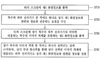
A method of controlling a mobile terminal according to the present invention includes: outputting first screen information to a touch screen; Receiving a request to transmit information associated with the first screen information to at least one of a plurality of external electronic devices; Outputting second screen information including a plurality of image objects corresponding to each of the plurality of external electronic devices on the touch screen; And transmitting information related to the first screen information to an external electronic device corresponding to the selected image object through the wireless communication unit based on at least one of the plurality of image objects being selected.
According to the present invention, when screen information is output to the touch screen, the screen information may be output from the external electronic device if the distance between the mobile terminal and the external electronic device is within a predetermined distance. Accordingly, the user can more easily transmit the screen information from the mobile terminal to the external electronic device.
In addition, according to the present invention, when there are a plurality of external electronic devices, different screen information of the mobile terminal can be transmitted to each external electronic device. Accordingly, the user can receive various screen information of the mobile terminal simultaneously through a plurality of external electronic devices.
Further, according to the present invention, a user can conveniently select an external electronic device to transmit screen information by using a plurality of image objects corresponding to a plurality of external electronic devices. In addition, the plurality of image objects are output on the touch screen along one direction corresponding to the arrangement of the plurality of external electronic devices, so that the user can more intuitively select the external electronic device through the image object.
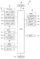
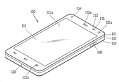
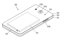
1A to 1C are block diagrams for explaining a mobile terminal according to the present invention, and FIGS. 1B and 1C are conceptual diagrams showing an example of a mobile terminal according to the present invention in different directions.
2A is a flowchart of a control method related to transmitting screen information to an external electronic device in a mobile terminal according to the present invention. FIG. 2B is a conceptual diagram for explaining the control method of FIG. 2A.
3A and 3B are conceptual diagrams for explaining a control method related to transmitting screen information to a mobile terminal in an external electronic device related to the present invention.
4A to 4C are conceptual diagrams illustrating a control method related to outputting a predetermined idle screen instead of screen information in an external electronic device related to the present invention.
5 is a conceptual diagram for explaining a control method related to outputting new image information stored in a main body or a predetermined server in an external electronic device related to the present invention.
6 is a conceptual diagram for explaining a control method related to outputting information related to a notification event in an external electronic device related to the present invention.
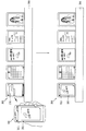
7A is a flowchart of a control method for transmitting screen information to an external electronic device selected by a user among a plurality of external electronic devices in the mobile terminal according to the present invention. FIG. 7B is a flowchart for explaining the control method of FIG. 7A.
8A to 8C are conceptual diagrams for explaining a control method related to setting a relative position between a plurality of image objects related to the present invention.
9A to 9B are conceptual diagrams for explaining an embodiment in which any one of a plurality of image objects is selected based on the movement of the main body related to the present invention.
10A to 10D are conceptual diagrams illustrating an embodiment in which a plurality of image objects and first screen information related to the present invention are output to different areas of a touch screen.
11A to 11B are conceptual diagrams for explaining a control method related to the transmission of different screen information to a plurality of external electronic devices related to the present invention at the same time.
12A and 12B are conceptual diagrams for explaining a control method related to selection of an external electronic device to which screen information is to be transmitted through a predetermined type of touch associated with an external electronic device related to the present invention.
13A and 13B are conceptual diagrams illustrating various configurations of external electronic devices related to the present invention.
14A and 14B are conceptual diagrams for explaining how charging is performed in a state where external electronic devices related to the present invention are in contact with each other.
Hereinafter, embodiments of the present invention will be described in detail with reference to the accompanying drawings, wherein like or similar elements are denoted by the same reference numerals, and redundant description thereof will be omitted. The suffix "module" and " part "for the components used in the following description are given or mixed in consideration of ease of specification, and do not have their own meaning or role. In the following description of the embodiments of the present invention, a detailed description of related arts will be omitted when it is determined that the gist of the embodiments disclosed herein may be blurred. It is to be understood that both the foregoing general description and the following detailed description are exemplary and explanatory and are intended to provide further explanation of the invention as claimed. , ≪ / RTI > equivalents, and alternatives.
Terms including ordinals, such as first, second, etc., may be used to describe various elements, but the elements are not limited to these terms. The terms are used only for the purpose of distinguishing one component from another.
It is to be understood that when an element is referred to as being "connected" or "connected" to another element, it may be directly connected or connected to the other element, . On the other hand, when an element is referred to as being "directly connected" or "directly connected" to another element, it should be understood that there are no other elements in between.
The singular expressions include plural expressions unless the context clearly dictates otherwise.
In the present application, the terms "comprises", "having", and the like are used to specify that a feature, a number, a step, an operation, an element, a component, But do not preclude the presence or addition of one or more other features, integers, steps, operations, elements, components, or combinations thereof.
The mobile terminal described in this specification includes a mobile phone, a smart phone, a laptop computer, a digital broadcasting terminal, a personal digital assistant (PDA), a portable multimedia player (PMP), a navigation device, a slate PC A tablet PC, an ultrabook, a wearable device such as a smartwatch, a smart glass, and a head mounted display (HMD). have.
However, it will be appreciated by those skilled in the art that the configuration according to the embodiments described herein may be applied to fixed terminals such as a digital TV, a desktop computer, a digital signage, and the like, will be.
1A to 1C are block diagrams for explaining a mobile terminal according to the present invention, and FIGS. 1B and 1C are conceptual diagrams showing an example of a mobile terminal according to the present invention in different directions.
The
The
The
The
The
The
The
In addition, the
In addition to the operations related to the application program, the
In addition, the
The
At least some of the components may operate in cooperation with one another to implement a method of operation, control, or control of a mobile terminal according to various embodiments described below. In addition, the operation, control, or control method of the mobile terminal may be implemented on the mobile terminal by driving at least one application program stored in the
Hereinafter, the various components of the
First, referring to the
The mobile communication module 112 may be a mobile communication module or a mobile communication module such as a mobile communication module or a mobile communication module that uses technology standards or a communication method (e.g., Global System for Mobile communication (GSM), Code Division Multi Access (CDMA), Code Division Multi Access 2000 (Enhanced Voice-Data Optimized or Enhanced Voice-Data Only), Wideband CDMA (WCDMA), High Speed Downlink Packet Access (HSDPA), High Speed Uplink Packet Access (HSUPA), Long Term Evolution And an external terminal, or a server on a mobile communication network established according to a long term evolution (AR), a long term evolution (AR), or the like.
The wireless signal may include various types of data depending on a voice call signal, a video call signal or a text / multimedia message transmission / reception.
The wireless Internet module 113 is a module for wireless Internet access, and may be built in or externally attached to the
Wireless Internet technologies include, for example, wireless LAN (WLAN), wireless fidelity (Wi-Fi), wireless fidelity (Wi-Fi) Direct, DLNA (Digital Living Network Alliance), WiBro Interoperability for Microwave Access, High Speed Downlink Packet Access (HSDPA), High Speed Uplink Packet Access (HSUPA), Long Term Evolution (LTE) and Long Term Evolution-Advanced (LTE-A) 113 transmit and receive data according to at least one wireless Internet technology, including Internet technologies not listed above.
The wireless Internet module 113 for performing a wireless Internet connection through the mobile communication network can be used for wireless Internet access by WiBro, HSDPA, HSUPA, GSM, CDMA, WCDMA, LTE or LTE- May be understood as a kind of the mobile communication module 112.
The short-
Here, the other
The position information module 115 is a module for obtaining the position (or current position) of the mobile terminal, and a representative example thereof is a Global Positioning System (GPS) module or a Wireless Fidelity (WiFi) module. For example, when the mobile terminal utilizes the GPS module, it can acquire the position of the mobile terminal by using a signal transmitted from the GPS satellite. As another example, when the mobile terminal utilizes the Wi-Fi module, it can acquire the position of the mobile terminal based on information of a wireless access point (AP) that transmits or receives the wireless signal with the Wi-Fi module. Optionally, the location information module 115 may perform any of the other functions of the
Next, the
The
The
Meanwhile, the
First, the
Examples of the
On the other hand, for convenience of explanation, the act of recognizing that the object is located on the touch screen in proximity with no object touching the touch screen is referred to as "proximity touch & The act of actually touching an object on the screen is called a "contact touch. &Quot; The position at which the object is closely touched on the touch screen means a position where the object corresponds to the touch screen vertically when the object is touched. The
The touch sensor senses a touch (or touch input) applied to the touch screen (or the display unit 151) by using at least one of various touch methods such as a resistance film type, a capacitive type, an infrared type, an ultrasonic type, do.
For example, the touch sensor may be configured to convert a change in a pressure applied to a specific portion of the touch screen or a capacitance generated in a specific portion to an electrical input signal. The touch sensor may be configured to detect a position, an area, a pressure at the time of touch, a capacitance at the time of touch, and the like where a touch object touching the touch screen is touched on the touch sensor. Here, the touch object may be a finger, a touch pen, a stylus pen, a pointer, or the like as an object to which a touch is applied to the touch sensor.
Thus, when there is a touch input to the touch sensor, the corresponding signal (s) is sent to the touch controller. The touch controller processes the signal (s) and transmits the corresponding data to the
On the other hand, the
On the other hand, the touch sensors and the proximity sensors discussed above can be used independently or in combination to provide a short touch (touch), a long touch, a multi touch, a drag touch ), Flick touch, pinch-in touch, pinch-out touch, swipe touch, hovering touch, and the like. Touch can be sensed.
The ultrasonic sensor can recognize the position information of the object to be sensed by using ultrasonic waves. Meanwhile, the
The
The
The
Also, the
In the stereoscopic display unit, a three-dimensional display system such as a stereoscopic system (glasses system), an autostereoscopic system (no-glasses system), and a projection system (holographic system) can be applied.
The
The
In addition to vibration, the
The
The
The signal output from the
The
The identification module is a chip for storing various information for authenticating the use right of the
The
The
The
Meanwhile, as described above, the
In addition, the
The
In addition, the
As another example, the
In the following, various embodiments may be embodied in a recording medium readable by a computer or similar device using, for example, software, hardware, or a combination thereof.
Referring to FIGS. 1B and 1C, the disclosed
Here, the terminal body can be understood as a concept of referring to the
The
A
In some cases, electronic components may also be mounted on the
As shown, when the
These
The
Meanwhile, the
The
1B and 1C, a
However, these configurations are not limited to this arrangement. These configurations may be excluded or replaced as needed, or placed on different planes. For example, the
The
The
In addition, the
The
The touch sensor may be a film having a touch pattern and disposed between the
In this way, the
The first
The
The
The
The first and
In this figure, the
The contents input by the first and
On the other hand, a rear input unit (not shown) may be provided on the rear surface of the terminal body as another example of the
The rear input unit may be disposed so as to overlap with the
When a rear input unit is provided on the rear surface of the terminal body, a new type of user interface using the rear input unit can be realized. When the
Meanwhile, the
The
The
And a
The
The
And a second
The terminal body may be provided with at least one antenna for wireless communication. The antenna may be embedded in the terminal body or formed in the case. For example, an antenna constituting a part of the broadcast receiving module 111 (see FIG. 1A) may be configured to be able to be drawn out from the terminal body. Alternatively, the antenna may be formed in a film type and attached to the inner surface of the
The terminal body is provided with a power supply unit 190 (see FIG. 1A) for supplying power to the
The
The
The
Meanwhile, the
Here, the external
For example, the external
The external
More specifically, the wireless communication unit 210 performs a wireless communication between the external
The wireless communication unit 210 may include a short range communication module 214. The short-range communication module 214 is for short-range communication, and includes Bluetooth ™, Radio Frequency Identification (RFID), Infrared Data Association (IrDA), Ultra Wideband (UWB), ZigBee, NFC (Near Field Communication), Wi-Fi (Wireless-Fidelity), Wi-Fi Direct, and Wireless USB (Wireless Universal Serial Bus) technology.
Further, the external
For example, the plurality of external electronic devices may be disposed in the
As another example, a magnet may be disposed on the opposite side of the surface on which the
Meanwhile, in the present invention, information related to screen information output from the
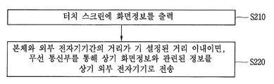
2A is a flowchart of a control method related to transmitting
Referring to FIG. 2A, the
Here, the
Referring to FIG. 2B, the
2A, when the distance between the main body and the external
Specifically, the
That is, if the distance between the
When communication is established between the
Alternatively, the
When information related to the
2B, when a plurality of the external
After the
In other words, if the distance between the
Accordingly, the external
If the distance between the
3A and 3B are conceptual diagrams for explaining a control method related to transmitting
Referring to FIG. 3A, in the external
3A, when the distance between the
For example, if the distance between the external
Here, the execution screen output from the external
3B, in the case of the predetermined external
For example, if the distance between the predetermined external
Meanwhile, the screen information output from the external
In this case, in the external
4A to 4C are conceptual diagrams illustrating a control method related to outputting a predetermined idle screen instead of screen information in an external electronic device related to the present invention.
4A and 4B, in the external
The control unit may transmit a control command related to the output of the
Here, the distance associated with the privacy protection may be a distance set to be longer than a predetermined distance related to Figs. 2A to 2B and Figs. 3A and 3B.
In the present specification, a distance related to the transmission of information related to screen information from the
In other words, the distances referred to in the portions described with reference to Figs. 2A to 3B are the first distances, and the distances to be referred to in the portions described with reference to Figs. 4A to 4B are referred to as the second distances. Generally, the second distance may be a distance set longer than the first distance.
4A and 4B, when the distance between the
For example, the
In the case where a plurality of external electronic devices are arranged adjacent to each other as shown in the figure, the information included in the
When the distance between the
Here, the
The output of the
Meanwhile, in another embodiment of the present invention, it is possible to control the output of the
Specifically, the
Referring to FIG. 4C, when the front surface of the main body is disposed in the gravity direction (for example, the g direction), the
When the control command is received, the external
In the case where a plurality of external electronic devices are arranged adjacent to each other as shown in the figure, the information included in the
4C, when the front surface of the
In the external
In the case where a plurality of external electronic apparatuses are arranged adjacent to each other as shown in the drawing, in each of the external electronic apparatuses, each of the
Up to now, a control method related to the output of a standby screen output from an external electronic device has been described.
Meanwhile, in an embodiment of the present invention, when new image information is stored in the
5 is a conceptual diagram for explaining a control method related to outputting new image information stored in the
5, the
Here, when there are a plurality of the external
In addition, the distance between the
Here, the
For example, the image satisfying the predetermined condition may be an image including a predetermined object image. The
Accordingly, even if there is no request related to a separate image transmission by the user, the external
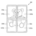
The
6 is a conceptual diagram for explaining a control method related to outputting information related to a notification event in the external
6, when a predetermined notification event is generated in the
6, in a state where a plurality of external
Here, the notification event may be a notification event for a missed call, a missed message, an alarm of a predetermined application, etc., generated in the main body. Alternatively, the notification event may be a notification event previously set by the user. In this case, the notification event may be a notification event related to the schedule.
On the other hand, when there are a plurality of external electronic devices, the
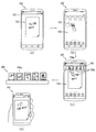
7A is a flowchart of a control method for transmitting screen information to an external electronic device selected by a user among a plurality of external electronic devices in the
Referring to FIG. 7A, the
Here, the
Referring to FIG. 7A, the
The manner in which the user request is received may vary. As an example of how the user request is received, it may be that the application associated with the present invention is executed.
As shown in (b) of FIG. 7, the
7A, when the user request is received, the
Specifically, the
At least a portion of the
In addition, when the user request is executed by executing the application, the
Alternatively, although not shown, the user request may be received on the basis of a touch of a predetermined type being applied to the
Referring to FIG. 7A, the
7D, if a touch is applied to any one of the plurality of image objects 730, the external
Meanwhile, the
According to the present invention, the arrangement order of the plurality of image objects 730 is controlled by the
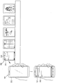
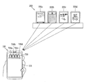
8A to 8C are conceptual diagrams for explaining a control method related to setting of a relative position between a plurality of image objects 200 related to the present invention.
The
8A, the
More specifically, in each of the external
Meanwhile, in the step of receiving a radio signal from each of the external
In other words, the
As described above, the control unit generates information related to the relative position between the respective external
In this case, the
For example, referring to FIG. 8A, the
In addition, the
In addition, the controller determines that the second and third external
In addition, the controller may determine that the second external
Similarly, the control unit determines that the third external
The
730b, 730c, and 730d on the
Information related to the relative position between the respective external
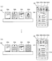
Hereinafter, an example will be described in which information related to a relative position between each of the external
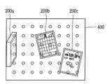
Referring to FIG. 8B, a plurality of external
When the plurality of external
8C, a plurality of external
Specifically, a plurality of connection portions may be formed on the
In this case, information related to the relative position between the external
The
The plurality of image objects 730a, 730b, and 730c on the
Meanwhile, in the mobile terminal according to the present invention, any one of the plurality of image objects can be selected through various methods. Hereinafter, various embodiments will be described with reference to the drawings.
9A to 9B are conceptual diagrams for explaining an embodiment in which any one of a plurality of image objects is selected based on the movement of the main body related to the present invention.
The
For example, the attitude and movement of the main body may be detected by an acceleration sensor, a magnetic sensor, a G-sensor, a gyroscope sensor, Or the like.
The
Referring to FIG. 9A, a plurality of image objects 910 corresponding to a plurality of external electronic devices may be output to the
9A, 9A and 9B, the
9A and 9B, when the touch is released, the
In the foregoing, an embodiment has been described in which a plurality of image objects are displayed on the
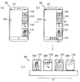
10A to 10D are conceptual diagrams illustrating an embodiment in which a plurality of image objects and first screen information related to the present invention are output to different areas of a touch screen.
Referring to FIG. 10A, a plurality of
Referring to FIGS. 10A and 10B, the
A plurality of
Referring to FIG. 10B, when a dragging touch in a predetermined direction is applied to one area of the
The first screen information may be an
Further, in the present invention, the first screen information may be an
Referring to FIG. 10C, when an application related to the present invention is executed, a
As described above, the first screen information may be
Referring to FIGS. 10 (a) and 10 (b), when a predetermined type of touch (for example, dragging in one direction) is applied to the
In other words, the first screen information may be changed from the
Referring to FIGS. 10C and 10C, a drag touch starting from the first screen information 1020 (in this case, the screen information related to the execution image of the third application) The
Referring to FIGS. 10D and 10D, if a predetermined type of touch is applied to any one of the plurality of
Specifically, a drag-touch operation is performed on any one of the plurality of
Up to now, we have seen that some of the external electronic devices are selected by the user and the screen information is transferred to the selected external electronic device. On the other hand, in the present invention, different screen information may be simultaneously transmitted to a plurality of external electronic devices. This will be described with reference to the drawings.
11A and 11B are conceptual diagrams for explaining a control method related to the transmission of different screen information to a plurality of external electronic devices related to the present invention at the same time.
Referring to FIG. 11A,
Referring to FIGS. 11A and 11A, when a predetermined type of touch is applied to the first screen information 1100 (for example, a tap touch to tap the touch screen a plurality of times) The
The
Referring to FIGS. 11A and 11A, when the
Further, in each of the external
Referring to FIGS. 11B and 11B, when the
Referring to FIGS. 11B and 11B, when the
In this case, the
On the other hand, a plurality of external electronic devices associated with the present invention may be associated with touches of predetermined methods, and an external electronic device through which the screen information is to be transmitted through the associated touch sensed by the touch screen may be selected. This will be described more specifically with reference to the drawings.
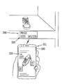
FIGS. 12A and 12B are conceptual diagrams for explaining a control method related to selecting an external electronic device to which screen information is to be transmitted through a predetermined type of touch associated with an external electronic device related to the present invention.
12A and 12A, when the
Referring to (a) of FIG. 12, when an event such as message reception is generated on the
The
Referring to FIG. 12B, an
Here, the touch of the preset method can be understood as a touch of a predetermined pattern.
In addition, the control unit may perform a touch operation (for example, one time, two times, three times, and four times) in different ways based on information related to the relative positions of the plurality of external electromagnetic periods, And can be linked to the
On the other hand, each of the external
13A and 13B are conceptual diagrams illustrating various configurations of external electronic devices related to the present invention. 14A and 14B are conceptual diagrams for explaining that charging is performed in a state where external electronic devices related to the present invention are in contact with each other.
More specifically, each external electronic device may be provided with a sensing unit (not shown) for sensing another external electronic device. Through the sensing unit, each of the external electronic devices can sense whether or not they are in contact with each other.
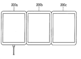
Referring to FIG. 13A, when a plurality of external
Further, when receiving a request related to the transmission of the first screen information 1310, the
Referring to FIG. 13B, each of the external
Also, a magnet may be disposed on one side of the external
14A and 14B, when power is supplied to any one of the plurality of external
The present invention described above can be embodied as computer-readable codes on a medium on which a program is recorded. The computer readable medium includes all kinds of recording devices in which data that can be read by a computer system is stored. Examples of the computer readable medium include a hard disk drive (HDD), a solid state disk (SSD), a silicon disk drive (SDD), a ROM, a RAM, a CD-ROM, a magnetic tape, a floppy disk, , And may also be implemented in the form of a carrier wave (e.g., transmission over the Internet). Also, the computer may include a
Claims (20)
A wireless communication unit configured to perform communication with an external electronic device;
A touch screen disposed on a front surface of the main body and outputting screen information; And
Wherein when the distance between the main body and the external electronic device is within a preset distance, information related to the screen information is transmitted through the wireless communication unit to the external electronic device so that screen information output from the touch screen is output from the external electronic device To the mobile terminal.
Wherein,
When the distance between the main body and the external electronic device is within a predetermined distance in a state where the touch screen is inactivated, information related to the screen information being output from the external electronic device is output to the touch screen, Wherein the mobile terminal receives information related to the screen information from the external electronic device.
Wherein,
If the distance between the main body and the external electronic device exceeds a distance related to privacy protection set farther than the distance,
Wherein the control unit transmits a control command related to the standby screen output to the external electronic device through the wireless communication unit so that the standby screen is output from the external electronic device.
Wherein,
Wherein when the distance between the main body and the external electronic device is within a distance related to the privacy protection in a state that the standby screen is output from the external electronic device, And transmits the screen information and a control command related to the output to the external electronic device.
The main body is provided with a sensing unit for sensing a direction of gravity with respect to the main body,
Wherein,
Wherein when the front surface of the main body is disposed in a direction opposite to the gravity direction, a control command related to maintaining the output of the screen information through the wireless communication unit is transmitted to the external electronic device,
Wherein when the front surface of the main body is disposed in the gravity direction, a control command related to outputting a predetermined idle screen through the wireless communication unit is transmitted to the external electronic device.
Wherein,
Wherein when the new image information is stored in the main body or the predetermined server, information related to the image information is transmitted to the external electronic device through the wireless communication unit such that the image information is output from the external electronic device terminal.
Wherein,
When a preset notification event is generated in the main body,
Wherein information related to the notification event is transmitted to the external electronic device through the wireless communication unit such that information related to the notification event is output from the external electronic device.
A touch screen configured to output first screen information; And
When receiving a request to transmit information related to the first screen information to at least one of the plurality of external electronic devices, displaying second screen information including a plurality of image objects corresponding to each of the plurality of external electronic devices And a control unit for controlling the touch screen,
Wherein,
And transmits information related to the first screen information to an external electronic device corresponding to the selected image object through the wireless communication unit based on at least one of the plurality of image objects being selected.
Wherein,
Wherein the setting unit sets a relative position of each image object output to the touch screen based on information related to a relative position of an external electromagnetic time period corresponding to each image object.
Wherein,
And generates information related to a relative position between each of the external electronic devices based on a signal intensity received from each of the external electronic devices.
Wherein,
When the plurality of external electronic devices are respectively arranged in a plurality of connection portions formed in a predetermined order,
And generates information related to a relative position between each of the external electronic devices based on information related to a predetermined order of the respective connection portions.
And the second screen information includes first screen information.
Wherein at least a part of the first screen information is outputted so as to overlap with the image object.
Wherein,
When the drag-and-touch starting from the first screen information is released from any one of the plurality of image objects, the first screen information is transmitted to the external electronic device corresponding to the one of the plurality of image objects through the wireless communication unit To the mobile terminal.
And a sensing unit for sensing at least one of movement and posture of the main body,
Wherein one of the plurality of image objects is selected based on at least one of an attitude and a motion of the main body.
Wherein,
Wherein the control unit controls the touch screen so that an indication for emphasizing the selected image object is output based on at least one of the plurality of image objects being selected.
Wherein,
When the first screen information includes information related to execution screens of a plurality of recently executed applications,
When a request to transmit information related to the first screen information to the plurality of external electronic devices is received,
An execution screen of the plurality of applications is output to the plurality of external electronic devices,
And the execution screens of the plurality of applications are respectively transmitted to the plurality of external electronic devices via the wireless communication unit.
Wherein,
When a predetermined type of touch is applied to the touch screen in a state in which the first screen information is outputted,
Wherein the first screen information is output from an external electronic device to which the touch is connected among the plurality of external electronic devices,
And transmits the first screen information to an external electronic device to which the touch is connected through the wireless communication unit.
Wherein,
Wherein the mobile terminal associates each of the external electronic devices with a touch of a different type based on information related to a relative position between the plurality of external electronic devices.
Receiving a request to transmit information associated with the first screen information to at least one of a plurality of external electronic devices;
Outputting second screen information including a plurality of image objects corresponding to each of the plurality of external electronic devices on the touch screen; And
Transmitting information related to the first screen information to an external electronic device corresponding to the selected image object through the wireless communication unit based on at least one of the plurality of image objects being selected; Way.
Priority Applications (1)
| Application Number | Priority Date | Filing Date | Title |
|---|---|---|---|
| KR1020150137047A KR20170037431A (en) | 2015-09-25 | 2015-09-25 | Mobile terminal and control method for the mobile terminal |
Applications Claiming Priority (1)
| Application Number | Priority Date | Filing Date | Title |
|---|---|---|---|
| KR1020150137047A KR20170037431A (en) | 2015-09-25 | 2015-09-25 | Mobile terminal and control method for the mobile terminal |
Publications (1)
| Publication Number | Publication Date |
|---|---|
| KR20170037431A true KR20170037431A (en) | 2017-04-04 |
Family
ID=58588614
Family Applications (1)
| Application Number | Title | Priority Date | Filing Date |
|---|---|---|---|
| KR1020150137047A KR20170037431A (en) | 2015-09-25 | 2015-09-25 | Mobile terminal and control method for the mobile terminal |
Country Status (1)
| Country | Link |
|---|---|
| KR (1) | KR20170037431A (en) |
Cited By (2)
| Publication number | Priority date | Publication date | Assignee | Title |
|---|---|---|---|---|
| WO2020141808A1 (en) * | 2019-01-04 | 2020-07-09 | 삼성전자 주식회사 | Electronic device and method for editing content of external device |
| KR102165198B1 (en) * | 2020-01-20 | 2020-10-13 | 주식회사 해광 | Rack for electronic device and electronic device system including the same |
-
2015
- 2015-09-25 KR KR1020150137047A patent/KR20170037431A/en unknown
Cited By (3)
| Publication number | Priority date | Publication date | Assignee | Title |
|---|---|---|---|---|
| WO2020141808A1 (en) * | 2019-01-04 | 2020-07-09 | 삼성전자 주식회사 | Electronic device and method for editing content of external device |
| US11810231B2 (en) | 2019-01-04 | 2023-11-07 | Samsung Electronics Co., Ltd. | Electronic device and method for editing content of external device |
| KR102165198B1 (en) * | 2020-01-20 | 2020-10-13 | 주식회사 해광 | Rack for electronic device and electronic device system including the same |
Similar Documents
| Publication | Publication Date | Title |
|---|---|---|
| KR20150142933A (en) | Watch type terminal and control method thereof | |
| KR20160092363A (en) | Mobile terminal and method for controlling the same | |
| KR20170024846A (en) | Mobile terminal and method for controlling the same | |
| KR20160036920A (en) | Mobile terminal and method for controlling the same | |
| KR20180005521A (en) | Mobile terminal and method for controlling the same | |
| KR20160023188A (en) | Mobile terminal and method for controlling the same | |
| KR20150084133A (en) | Mobile terminal and method for controlling the same | |
| KR101602269B1 (en) | Mobile terminal and control method for the mobile terminal | |
| KR101510704B1 (en) | Mobile terminal and control method for the mobile terminal | |
| KR20170052190A (en) | Terminal device and controlling method thereof | |
| KR20170021514A (en) | Display apparatus and controlling method thereof | |
| KR101604814B1 (en) | Mobile terminal and control method thereof | |
| KR20170037431A (en) | Mobile terminal and control method for the mobile terminal | |
| KR20170071215A (en) | Mobile terminal and method for controlling the same | |
| KR20170019910A (en) | Mobile terminal and method for controlling the same | |
| KR20160076273A (en) | Mobile terminal and method for controlling the same | |
| KR20160077907A (en) | Mobile terminal and method for controlling the same | |
| KR20160039953A (en) | Mobile terminal and method for controlling the same | |
| KR101613960B1 (en) | Watch type mobile terminal and control method for the mobile terminal | |
| KR101669210B1 (en) | Mobile terminal | |
| KR20160015720A (en) | Mobile terminal and method for controlling the same | |
| KR20160073038A (en) | Mobile terminal and method for controlling the same | |
| KR101641565B1 (en) | Mobile terminal and method for controlling the same | |
| KR101698099B1 (en) | Mobile terminal and control method for the mobile terminal | |
| KR20170068033A (en) | Mobile terminal and method for controlling the same |