KR20170032003A - Ballast stabilizer compatible Lamp with a leakage-current protection circuit - Google Patents
Ballast stabilizer compatible Lamp with a leakage-current protection circuit Download PDFInfo
- Publication number
- KR20170032003A KR20170032003A KR1020150129707A KR20150129707A KR20170032003A KR 20170032003 A KR20170032003 A KR 20170032003A KR 1020150129707 A KR1020150129707 A KR 1020150129707A KR 20150129707 A KR20150129707 A KR 20150129707A KR 20170032003 A KR20170032003 A KR 20170032003A
- Authority
- KR
- South Korea
- Prior art keywords
- switch module
- external power
- protection circuit
- input terminal
- lamp
- Prior art date
Links
Images


Classifications
-
- F—MECHANICAL ENGINEERING; LIGHTING; HEATING; WEAPONS; BLASTING
- F21—LIGHTING
- F21K—NON-ELECTRIC LIGHT SOURCES USING LUMINESCENCE; LIGHT SOURCES USING ELECTROCHEMILUMINESCENCE; LIGHT SOURCES USING CHARGES OF COMBUSTIBLE MATERIAL; LIGHT SOURCES USING SEMICONDUCTOR DEVICES AS LIGHT-GENERATING ELEMENTS; LIGHT SOURCES NOT OTHERWISE PROVIDED FOR
- F21K9/00—Light sources using semiconductor devices as light-generating elements, e.g. using light-emitting diodes [LED] or lasers
-
- F—MECHANICAL ENGINEERING; LIGHTING; HEATING; WEAPONS; BLASTING
- F21—LIGHTING
- F21V—FUNCTIONAL FEATURES OR DETAILS OF LIGHTING DEVICES OR SYSTEMS THEREOF; STRUCTURAL COMBINATIONS OF LIGHTING DEVICES WITH OTHER ARTICLES, NOT OTHERWISE PROVIDED FOR
- F21V25/00—Safety devices structurally associated with lighting devices
- F21V25/10—Safety devices structurally associated with lighting devices coming into action when lighting device is overloaded, e.g. thermal switch
-
- H—ELECTRICITY
- H05—ELECTRIC TECHNIQUES NOT OTHERWISE PROVIDED FOR
- H05B—ELECTRIC HEATING; ELECTRIC LIGHT SOURCES NOT OTHERWISE PROVIDED FOR; CIRCUIT ARRANGEMENTS FOR ELECTRIC LIGHT SOURCES, IN GENERAL
- H05B45/00—Circuit arrangements for operating light-emitting diodes [LED]
- H05B45/30—Driver circuits
- H05B45/37—Converter circuits
-
- F—MECHANICAL ENGINEERING; LIGHTING; HEATING; WEAPONS; BLASTING
- F21—LIGHTING
- F21V—FUNCTIONAL FEATURES OR DETAILS OF LIGHTING DEVICES OR SYSTEMS THEREOF; STRUCTURAL COMBINATIONS OF LIGHTING DEVICES WITH OTHER ARTICLES, NOT OTHERWISE PROVIDED FOR
- F21V23/00—Arrangement of electric circuit elements in or on lighting devices
- F21V23/003—Arrangement of electric circuit elements in or on lighting devices the elements being electronics drivers or controllers for operating the light source, e.g. for a LED array
-
- F—MECHANICAL ENGINEERING; LIGHTING; HEATING; WEAPONS; BLASTING
- F21—LIGHTING
- F21V—FUNCTIONAL FEATURES OR DETAILS OF LIGHTING DEVICES OR SYSTEMS THEREOF; STRUCTURAL COMBINATIONS OF LIGHTING DEVICES WITH OTHER ARTICLES, NOT OTHERWISE PROVIDED FOR
- F21V25/00—Safety devices structurally associated with lighting devices
- F21V25/02—Safety devices structurally associated with lighting devices coming into action when lighting device is disturbed, dismounted, or broken
- F21V25/04—Safety devices structurally associated with lighting devices coming into action when lighting device is disturbed, dismounted, or broken breaking the electric circuit
-
- H05B33/0815—
-
- H05B37/03—
-
- H—ELECTRICITY
- H05—ELECTRIC TECHNIQUES NOT OTHERWISE PROVIDED FOR
- H05B—ELECTRIC HEATING; ELECTRIC LIGHT SOURCES NOT OTHERWISE PROVIDED FOR; CIRCUIT ARRANGEMENTS FOR ELECTRIC LIGHT SOURCES, IN GENERAL
- H05B45/00—Circuit arrangements for operating light-emitting diodes [LED]
- H05B45/50—Circuit arrangements for operating light-emitting diodes [LED] responsive to malfunctions or undesirable behaviour of LEDs; responsive to LED life; Protective circuits
-
- H—ELECTRICITY
- H05—ELECTRIC TECHNIQUES NOT OTHERWISE PROVIDED FOR
- H05B—ELECTRIC HEATING; ELECTRIC LIGHT SOURCES NOT OTHERWISE PROVIDED FOR; CIRCUIT ARRANGEMENTS FOR ELECTRIC LIGHT SOURCES, IN GENERAL
- H05B47/00—Circuit arrangements for operating light sources in general, i.e. where the type of light source is not relevant
- H05B47/20—Responsive to malfunctions or to light source life; for protection
- H05B47/24—Circuit arrangements for protecting against overvoltage
-
- H—ELECTRICITY
- H05—ELECTRIC TECHNIQUES NOT OTHERWISE PROVIDED FOR
- H05B—ELECTRIC HEATING; ELECTRIC LIGHT SOURCES NOT OTHERWISE PROVIDED FOR; CIRCUIT ARRANGEMENTS FOR ELECTRIC LIGHT SOURCES, IN GENERAL
- H05B47/00—Circuit arrangements for operating light sources in general, i.e. where the type of light source is not relevant
- H05B47/20—Responsive to malfunctions or to light source life; for protection
- H05B47/26—Circuit arrangements for protecting against earth faults
-
- H—ELECTRICITY
- H05—ELECTRIC TECHNIQUES NOT OTHERWISE PROVIDED FOR
- H05B—ELECTRIC HEATING; ELECTRIC LIGHT SOURCES NOT OTHERWISE PROVIDED FOR; CIRCUIT ARRANGEMENTS FOR ELECTRIC LIGHT SOURCES, IN GENERAL
- H05B45/00—Circuit arrangements for operating light-emitting diodes [LED]
- H05B45/30—Driver circuits
- H05B45/357—Driver circuits specially adapted for retrofit LED light sources
- H05B45/3578—Emulating the electrical or functional characteristics of discharge lamps
-
- Y—GENERAL TAGGING OF NEW TECHNOLOGICAL DEVELOPMENTS; GENERAL TAGGING OF CROSS-SECTIONAL TECHNOLOGIES SPANNING OVER SEVERAL SECTIONS OF THE IPC; TECHNICAL SUBJECTS COVERED BY FORMER USPC CROSS-REFERENCE ART COLLECTIONS [XRACs] AND DIGESTS
- Y02—TECHNOLOGIES OR APPLICATIONS FOR MITIGATION OR ADAPTATION AGAINST CLIMATE CHANGE
- Y02B—CLIMATE CHANGE MITIGATION TECHNOLOGIES RELATED TO BUILDINGS, e.g. HOUSING, HOUSE APPLIANCES OR RELATED END-USER APPLICATIONS
- Y02B20/00—Energy efficient lighting technologies, e.g. halogen lamps or gas discharge lamps
- Y02B20/30—Semiconductor lamps, e.g. solid state lamps [SSL] light emitting diodes [LED] or organic LED [OLED]
Landscapes
- Engineering & Computer Science (AREA)
- General Engineering & Computer Science (AREA)
- Microelectronics & Electronic Packaging (AREA)
- Physics & Mathematics (AREA)
- Optics & Photonics (AREA)
- Circuit Arrangement For Electric Light Sources In General (AREA)
Abstract
Description
본 발명은 제1 외부 전원을 입력받는 제1 입력단, 제2 외부 전원을 입력받는 제2 입력단, 제1 입력단과 전기적으로 연결되어, 기 설정된 조건에 따라 스위치 온(on)/오프(off)하는 제1 스위치 모듈, 제2 입력단과 전기적으로 연결되어, 기 설정된 조건에 따라 스위치 온(on)/오프(off)하는 제2 스위치 모듈, 제1 스위치 모듈 및 제2 스위치 모듈과 전기적으로 연결되어, 과전압을 방지하는 과전압 보호 회로, 과전압 보호 회로와 전기적으로 연결되어, 제1 스위치 모듈, 제1 스위치 모듈, 과전압 보호 회로의 상태를 감지하고 제어하는 제어 모듈, 제어 모듈과 전기적으로 연결되어, 전원이 인가되면 빛을 조사하는 광원을 포함하는 누설전류 보호 회로를 구비한 안정기 호환형 램프에 관한 것이다.The present invention is characterized in that a first input terminal receiving a first external power supply, a second input terminal receiving a second external power supply, and a second input terminal electrically connected to the first input terminal are turned on / off A second switch module electrically connected to the first switch module and the second input terminal and electrically connected to the second switch module, the first switch module, and the second switch module that are switched on / off according to predetermined conditions, An overvoltage protection circuit for preventing an overvoltage, a control module electrically connected to the overvoltage protection circuit for detecting and controlling the state of the first switch module, the first switch module, and the overvoltage protection circuit, To a ballast-compatible lamp having a leakage current protection circuit including a light source that illuminates light when applied.
도 1을 참조하면, 형광램프 또는 LED(Light Emitting Diode)에는 안정기(Ballast Stabilizer)를 사용하게 되는데, 이러한 안정기는 높은 전압의 전기를 형성하고 지나치게 많은 전류가 흐르는 것을 방지하는 역할을 수행한다. 상용 전원(ex; 110V, 220V 전원)이 곧바로 전등과 연결되지 않고 안정기를 한번 거친 후 전등과 연결하는 것도 같은 이유이다.Referring to FIG. 1, a ballast stabilizer is used for a fluorescent lamp or an LED (Light Emitting Diode). The ballast stabilizes the high voltage electricity and prevents excessive current from flowing. It is also the reason why the commercial power supply (ex. 110V, 220V power supply) is not directly connected to the lamp, but is connected to the lamp after passing the ballast once.
이러한 안정기를 사용하는 안정기 호환형 램프의 경우, 사용자가 램프를 교체하거나 정비할 때 누설 전류(leakage current)에 의한 감전을 방지하기 위하여 접촉식 Push 방식 등 일반적인 기계식 스위치를 사용하고 있다.In the case of a ballast-compatible lamp using such a ballast, a general mechanical switch such as a contact type push type is used to prevent electric shock due to leakage current when the user changes or maintains the lamp.
그런데, 안정기를 적용한 램프의 경우, 처음 구동 전압이 약 1kV 이상 0.2초 동안 인가된다. 이 때, 기계식 스위치를 적용한 제품은 오랫동안 사용하게 되면 기계식 스위치 자체의 내부 금속 플레이트에 지속적으로 고압 전원이 인가된다. 따라서, 오픈 상태에 있어야 하는 기계식 스위치가 한순간 물리적으로 단락(short)상태에 빠지는 경우가 발생하며, 사용자에게 순간적인 감전의 위험을 가지게 되는 문제점이 존재하고 있었다. However, in the case of a lamp to which a ballast is applied, the first driving voltage is applied for about 0.2 seconds to about 1 kV. At this time, when the mechanical switch is used for a long time, the high voltage power is continuously applied to the inner metal plate of the mechanical switch itself. Therefore, there is a case where the mechanical switch, which should be in an open state, is temporarily short-circuited to a physical state, and there is a risk that the user is instantly exposed to a risk of electric shock.
또한, 기계식 스위치는 LED 램프에서 가장 중요한 이슈인 방수 적용이 불가하여, 스위치 사이에 습기가 침투함으로써 불량이 발생할 수 있는 요인이 존재한다. 따라서, 순간적인 과전압을 차단하고 누설 전류를 방지하는 안정기 호환형 램프의 구현 방안이 다양하게 연구되고 있었다.In addition, the mechanical switch can not be applied to the waterproofing, which is the most important issue in the LED lamp, and there is a factor that may cause defects due to penetration of moisture between the switches. Therefore, a variety of ballast - compatible lamps have been studied to prevent instantaneous overvoltage and prevent leakage current.
본 발명은 상술한 바와 같이 순간적인 감전을 방지하기 위하여 전자식 스위치를 포함하는 안정기 호환형 램프를 제공하는 것을 목적으로 한다.SUMMARY OF THE INVENTION It is an object of the present invention to provide a ballast-compatible lamp including an electronic switch for preventing momentary electric shock as described above.
본 발명이 이루고자 하는 기술적 과제는 이상에서 언급한 기술적 과제로 제한되지 않으며, 이하에서 설명할 내용으로부터 통상의 기술자에게 자명한 범위 내에서 다양한 기술적 과제가 포함될 수 있다. The technical problem to be solved by the present invention is not limited to the above-mentioned technical problems, and various technical problems can be included within the scope of what is well known to a person skilled in the art from the following description.
상기와 같은 과제를 해결하기 위한 본 발명의 일 실시예에 따른 누설전류 보호 회로를 구비한 안정기 호환형 램프는, 제1 외부 전원을 입력받는 제1 입력단, 제2 외부 전원을 입력받는 제2 입력단, 상기 제1 입력단과 전기적으로 연결되어, 기 설정된 조건에 따라 스위치 온(on)/오프(off)하는 제1 스위치 모듈, 상기 제2 입력단과 전기적으로 연결되어, 기 설정된 조건에 따라 스위치 온(on)/오프(off)하는 제2 스위치 모듈, 상기 제1 스위치 모듈 및 상기 제2 스위치 모듈과 전기적으로 연결되어, 과전압을 방지하는 과전압 보호 회로, 상기 과전압 보호 회로와 전기적으로 연결되어, 상기 제1 스위치 모듈, 상기 제1 스위치 모듈, 상기 과전압 보호 회로의 상태를 감지하고 제어하는 제어 모듈, 상기 제어 모듈과 전기적으로 연결되어, 전원이 인가되면 빛을 조사하는 광원을 포함하는 것을 특징으로 한다.According to an aspect of the present invention, there is provided a ballast-compatible lamp including a leakage current protection circuit including a first input terminal receiving a first external power supply, a second input terminal receiving a second external power supply, A first switch module that is electrically connected to the first input terminal and that is turned on / off according to predetermined conditions, and a second switch module that is electrically connected to the second input terminal, and an overvoltage protection circuit that is electrically connected to the first switch module and the second switch module to prevent an overvoltage, and a second overvoltage protection circuit that is electrically connected to the overvoltage protection circuit, 1 switch module, the first switch module, a control module for detecting and controlling the state of the overvoltage protection circuit, and a control module electrically connected to the control module, And a light source.
또한, 본 발명의 일 실시예에 따른 누설전류 보호 회로를 구비한 안정기 호환형 램프는, 상기 제1 외부 전원 또는 상기 제2 외부 전원이 상용 전원이 안정기에서 기 설정된 제1 외부 전원 및 제2 외부 전원으로 변환되어, 상기 제1 입력단 또는 상기 제2 입력단에 입력되는 것을 특징으로 한다.In the ballast-compatible lamp having the leakage current protection circuit according to an embodiment of the present invention, when the first external power or the second external power is supplied to the first external power source and the second external power source, Power source, and is input to the first input terminal or the second input terminal.
또한, 본 발명의 일 실시예에 따른 누설전류 보호 회로를 구비한 안정기 호환형 램프는, 상기 제1 입력단으로부터 입력된 상기 제1 외부 전원을 정류하여 상기 제1 스위치 모듈에 인가하는 제1 정류 회로, 상기 제2 입력단으로부터 입력된 상기 제2 외부 전원을 정류하여 상기 제2 스위치 모듈에 인가하는 제2 정류 회로를 더 포함하는 것을 특징으로 한다. 이 때, 상기 제1 정류 회로 또는 상기 제2 정류 회로는, 브릿지 다이오드인 것을 특징으로 한다.In addition, a ballast-compatible lamp having a leakage current protection circuit according to an embodiment of the present invention may include a first rectifier circuit for rectifying the first external power input from the first input terminal and applying the rectified first external power to the first switch module, And a second rectifying circuit rectifying the second external power inputted from the second input terminal and applying the rectified current to the second switch module. In this case, the first rectifying circuit or the second rectifying circuit is a bridge diode.
아울러, 본 발명의 일 실시예에 따른 누설전류 보호 회로를 구비한 안정기 호환형 램프는, 상기 제1 스위치 모듈 또는 상기 제2 스위치 모듈이 스위치 모듈이 오프(off) 상태인 경우, 반대 방향 전류를 차단하는 역 바이어스 다이오드, 기 설정된 전압 이상이 인가되면 동작하는 TVS 다이오드, 상기 TVS 다이오드의 손상을 방지하는 보호 저항, 기 설정된 조건에 따라 온(on)/오프(off) 하는 스위치 소자, 노이즈 필터링 역할을 수행하는 커패시터를 포함하는 것을 특징으로 한다.In addition, in the ballast-compatible lamp having the leakage current protection circuit according to the embodiment of the present invention, when the first switch module or the second switch module is in the off state, A TVS diode that operates when a predetermined voltage or more is applied, a protection resistor that prevents damage to the TVS diode, a switch element that turns on / off according to predetermined conditions, and a noise filtering function And a capacitor for performing the operation.
이 때, 본 발명의 일 실시예에 따른 누설전류 보호 회로를 구비한 안정기 호환형 램프는, 상기 스위치 소자가 사이리스터(SCR) 또는 FET인 것을 특징으로 한다. 또한, 상기 스위치 소자는, 스위치 소자에 인가되는 전압의 크기에 따라 온(on)/오프(off) 하는 것을 특징으로 한다. 또한, 상기 TVS 다이오드는, 다이오드에 인가되는 전압이 54V 이상인 경우 동작하는 것을 특징으로 한다.In this case, the ballast-compatible lamp having the leakage current protection circuit according to an embodiment of the present invention is characterized in that the switching element is a thyristor (SCR) or an FET. The switch element is turned on / off according to the magnitude of a voltage applied to the switch element. The TVS diode is operated when the voltage applied to the diode is 54 V or more.
또한, 본 발명의 일 실시예에 따른 누설전류 보호 회로를 구비한 안정기 호환형 램프는, 상기 제1 스위치 모듈의 출력단과 상기 제2 스위치 모듈의 출력단은 전기적으로 연결되는 것을 특징으로 한다.In addition, in the ballast-compatible lamp having the leakage current protection circuit according to an embodiment of the present invention, the output terminal of the first switch module and the output terminal of the second switch module are electrically connected.
한편, 본 발명의 일 실시예에 따른 누설전류 보호 회로를 구비한 안정기 호환형 램프는, 상기 제1 외부 전원이 정상적으로 입력되고 상기 제2 외부 전원이 오픈(open) 상태인 경우, 상기 제1 스위치 모듈은 온(on) 상태이고 상기 제2 스위치 모듈은 오프(off) 상태인 것을 특징으로 한다.Meanwhile, in the ballast-compatible lamp having the leakage current protection circuit according to an embodiment of the present invention, when the first external power is normally input and the second external power is in an open state, The module is in an on state and the second switch module is in an off state.
또한, 본 발명의 일 실시예에 따른 누설전류 보호 회로를 구비한 안정기 호환형 램프는, 상기 제1 외부 전원이 오픈(open) 상태이고 상기 제2 외부 전원이 정상적으로 입력되는 경우, 상기 제1 스위치 모듈은 오프(off) 상태이고 상기 제2 스위치 모듈은 온(on) 상태인 것을 특징으로 한다.In addition, in the ballast-compatible lamp having the leakage current protection circuit according to an embodiment of the present invention, when the first external power is in an open state and the second external power is normally input, The module is off and the second switch module is on.
또한, 본 발명의 일 실시예에 따른 누설전류 보호 회로를 구비한 안정기 호환형 램프는, 상기 광원이 LED인 것을 특징으로 한다. 또한, 상기 안정기 호환형 램프는, 일단에 제1 입력단, 타단에 제2 입력단이 존재하는 직관형 램프인 것을 특징으로 한다.Further, in the ballast-compatible lamp having the leakage current protection circuit according to an embodiment of the present invention, the light source is an LED. In addition, the ballast-compatible lamp is an intrinsic lamp having a first input end at one end and a second input end at the other end.
아울러, 본 발명의 일 실시예에 따른 누설전류 보호 회로를 구비한 안정기 호환형 램프는, 상기 제1 입력단은, 제1 외부 전원을 입력받는 제1 입력 전극을 더 포함하고, 상기 제2 입력단은, 제2 외부 전원을 입력받는 제2 입력 전극을 더 포함하는 것을 특징으로 한다.In addition, according to an embodiment of the present invention, there is provided a ballast-compatible lamp having a leakage current protection circuit, wherein the first input terminal further includes a first input electrode receiving a first external power supply, And a second input electrode receiving a second external power supply.
본 발명은 순간적인 감전을 방지하기 위하여 전자식 스위치를 포함하는 안정기 호환형 램프를 제공하여, 낙하 및 점등 불량 등의 사고로부터 소비자를 보호하는 것을 목적으로 한다.The present invention aims to provide a ballast-compatible lamp including an electronic switch for preventing instantaneous electric shock, thereby protecting consumers from accidents such as dropping and lighting failure.
또한, 종래의 기계식 스위치를 적용하는 경우 금형 및 조립 불량이 발생할 수 있으며, 금형이 교체에 4천~ 6천원 가량의 비용이 별도로 소모될 수 있다. 그러나, 본 발명의 누설전류 보호 회로를 구비한 안정기 호환형 램프는, 전자식 스위치를 사용하므로 별도의 금형 불량이 발생하는 문제점이 생기지 않는다.In addition, when a conventional mechanical switch is applied, a malfunction of a mold and an assembly may occur, and a cost of about 4,000 to 6,000 won may be separately consumed for replacement of a mold. However, since the ballast-compatible lamp including the leakage current protection circuit of the present invention uses an electronic switch, there is no problem that a separate mold failure occurs.
또한, 본 발명의 누설전류 보호 회로를 구비한 안정기 호환형 램프는, 방수 처리가 가능하므로 습도가 많은 지역(ex; 옥외 등)에 설치가 가능하여, 고객사가 설치하는 설치 자유도가 향상될 수 있다.In addition, since the ballast-compatible lamp having the leakage current protection circuit of the present invention can be waterproofed, it can be installed in an area with high humidity (ex. Outdoor) .
또한, 본 발명의 누설전류 보호 회로를 구비한 안정기 호환형 램프는, 직관형 램프의 양 단에 각각 스위치 모듈을 설치하여, 어느 단을 접촉하더라도 스위치 모듈이 오프 상태에 들어가게 되므로 감전 위험을 효과적으로 방지할 수 있게 된다.Further, in the ballast-compatible lamp having the leakage current protection circuit of the present invention, the switch module is provided at both ends of the straight tube lamp, so that the switch module is put into the off state regardless of which end is contacted, .
도 1은 종래 발명의 일 실시예에 따른 안정기 호환형 램프의 실시예를 나타내는 예시도이다.
도 2는 종래 발명의 일 실시예에 따른 안정기 호환형 램프의 실시예를 나타내는 예시도이다.
도 3은 본 발명의 일 실시예에 따른 누설전류 보호 회로를 구비한 안정기 호환형 램프를 나타내는 구성도이다.
도 4는 본 발명의 일 실시예에 따른 누설전류 보호 회로를 구비한 안정기 호환형 램프를 나타내는 예시도이다.
도 5a, 도 5b는 본 발명의 일 실시예에 따른 누설전류 보호 회로를 구비한 안정기 호환형 램프의 스위치 모듈의 실시예를 나타내는 구성도이다.
도 6은 본 발명의 일 실시예에 따른 누설전류 보호 회로를 구비한 안정기 호환형 램프가 과전압 상태에서 차단하게 되는 동작 방법을 나타내는 예시도이다.1 is an exemplary view showing an embodiment of a ballast-compatible lamp according to an embodiment of the present invention.
2 is an exemplary view showing an embodiment of a ballast-compatible lamp according to an embodiment of the present invention.
3 is a block diagram illustrating a ballast-compatible lamp having a leakage current protection circuit according to an embodiment of the present invention.
4 is an exemplary view illustrating a ballast-compatible lamp having a leakage current protection circuit according to an embodiment of the present invention.
5A and 5B are block diagrams illustrating an embodiment of a switch module of a ballast-compatible lamp having a leakage current protection circuit according to an embodiment of the present invention.
FIG. 6 is a diagram illustrating an exemplary operation of a ballast-compatible lamp having a leakage current protection circuit according to an exemplary embodiment of the present invention.
이하, 첨부된 도면들을 참조하여 본 발명에 따른 '누설전류 보호 회로를 구비한 안정기 호환형 램프'를 상세하게 설명한다. 설명하는 실시 예들은 본 발명의 기술 사상을 통상의 기술자가 용이하게 이해할 수 있도록 제공되는 것으로 이에 의해 본 발명이 한정되지 않는다. 또한, 첨부된 도면에 표현된 사항들은 본 발명의 실시 예들을 쉽게 설명하기 위해 도식화된 도면으로 실제로 구현되는 형태와 상이할 수 있다.DETAILED DESCRIPTION OF THE PREFERRED EMBODIMENTS Reference will now be made in detail to the preferred embodiments of the present invention, examples of which are illustrated in the accompanying drawings. The present invention is not limited to the above-described embodiments, and various changes and modifications may be made without departing from the scope of the present invention. In addition, the matters described in the attached drawings may be different from those actually implemented by the schematic drawings to easily describe the embodiments of the present invention.
한편, 이하에서 표현되는 각 구성부는 본 발명을 구현하기 위한 예일 뿐이다. 따라서, 본 발명의 다른 구현에서는 본 발명의 사상 및 범위를 벗어나지 않는 범위에서 다른 구성부가 사용될 수 있다.In the meantime, each constituent unit described below is only an example for implementing the present invention. Thus, in other implementations of the present invention, other components may be used without departing from the spirit and scope of the present invention.
또한, 어떤 구성요소들을 '포함'한다는 표현은, '개방형'의 표현으로서 해당 구성요소들이 존재하는 것을 단순히 지칭할 뿐이며, 추가적인 구성요소들을 배제하는 것으로 이해되어서는 안 된다. Also, the expression " comprising " is intended to merely denote that such elements are present as an expression of " open ", and should not be understood to exclude additional elements.
또한, '제1, 제2' 등과 같은 표현은, 복수의 구성들을 구분하기 위한 용도로만 사용된 표현으로써, 구성들 사이의 순서나 기타 특징들을 한정하지 않는다. Also, the expressions such as 'first, second', etc. are used only to distinguish between plural configurations, and do not limit the order or other features among the configurations.
또한, 본 발명의 '전원'은 '전압', '전력', '전류' 등 일반적인 전기 회로에 사용될 수 있는 전기 에너지의 모든 종류를 포함할 수 있다.The 'power source' of the present invention may include all kinds of electric energy that can be used in a general electric circuit such as 'voltage', 'electric power', 'electric current' and the like.
도 1, 도 2는 종래 발명의 일 실시예에 따른 안정기 호환형 램프의 실시예를 나타내는 예시도이다.FIG. 1 and FIG. 2 are views showing an embodiment of a ballast-compatible lamp according to an embodiment of the present invention.
도 1을 참조하면, 형광램프 또는 LED(Light Emitting Diode)에는 안정기(Ballast Stabilizer)를 사용하게 되는데, 이러한 안정기는 높은 전압의 전기를 형성하고 지나치게 많은 전류가 흐르는 것을 방지하는 역할을 수행한다. 상용 전원(ex; 110V, 220V 전원)이 곧바로 전등과 연결되지 않고 안정기를 한번 거친 후 전등과 연결하는 것도 같은 이유이다. 안정기는 전자식(Electronic) 또는 자석식(Magnetic) 등 수많은 종류의 안정기가 존재하며, 안정기의 성능과 종류에 따라서 램프의 성능도 좌우하게 될 정도로 중요한 역할을 수행한다.Referring to FIG. 1, a ballast stabilizer is used for a fluorescent lamp or an LED (Light Emitting Diode). The ballast stabilizes the high voltage electricity and prevents excessive current from flowing. It is also the reason why the commercial power supply (ex. 110V, 220V power supply) is not directly connected to the lamp, but is connected to the lamp after passing the ballast once. There are many kinds of ballasts such as electronic or magnetic, and they play an important role in determining the performance of the lamp depending on the performance and type of the ballast.
그런데, 도 2를 참조하면, 사용자(240)가 직관형 램프(230)의 교체 또는 유지보수를 하는 경우, 제2 전극(232)에 직접 닿게 되는 경우가 생긴다. 이 때, 상용 전원(210)과 연결된 안정기(220)가 직관형 램프의 제1 전극(231)을 통하여 전기가 통할 수 있게 되며, 지면(GND)에 있는 사용자에게 누설 전류가 흐를 수 있고 직관형 램프에 과전압이 인가될 수 있다.Referring to FIG. 2, when the
따라서, 직관형 램프는 과전압 인가로 인하여 파손과 손괴의 위험성이 생기며, 사용자는 감전의 위험이 존재하므로, 직관형 램프에는 안전을 위한 스위치를 더 포함하여 사용한다.Therefore, there is a risk of breakage and damage due to the overvoltage applied to the straight tube type lamp, and there is a risk of electric shock to the user. Therefore, the straight tube type lamp is further used for safety.
도 3은 본 발명의 일 실시예에 따른 누설전류 보호 회로를 구비한 안정기 호환형 램프를 나타내는 구성도이다.3 is a block diagram illustrating a ballast-compatible lamp having a leakage current protection circuit according to an embodiment of the present invention.
도 3을 참조하면, 본 발명의 누설전류 보호 회로를 구비한 안정기 호환형 램프는, 제1 입력단(310), 제2 입력단(320), 제1 스위치 모듈(330), 제2 스위치 모듈(340), 과전압 보호회로(350), 제어모듈(360), 광원(370)을 포함할 수 있다.Referring to FIG. 3, the ballast-compatible lamp having the leakage current protection circuit of the present invention includes a
제1 입력단(310)은 제1 외부 전원(311)을 입력받으며, 제2 입력단(320)은 제2 외부 전원(321)을 입력받는다. 이 때, 상기 제1 외부 전원 또는 상기 제2 외부 전원은, 상용 전원이 안정기에서 기 설정된 제1 외부 전원 및 제2 외부 전원으로 변환되어, 상기 제1 입력단 또는 상기 제2 입력단에 입력되는 것을 특징으로 한다.The
안정기는 안정기와 연결된 램프에 일정한 출력값과 소비전력을 줄 수 있도록 설치된다. 안정기를 설치하는 경우, 전기가 절약될 수 있는 효과가 있으며 안정기에 연결된 램프의 수명을 더 연장할 수 있는 장점이 있다. 또한, 안정기 호환형 램프를 사용하는 경우, 램프를 교체하더라도 호환이 용이하고 고장에 대한 우려가 줄어들 수 있다. 한편, 종래에 사용되는 형광등 안정기의 경우에도, 형광등 대체형 LED램프를 사용할 수 있다. 안정기 호환형 램프를 사용하는 경우, 여러 종류의 안정기를 사용하더라도 기존의 안정기와 램프가 호환되어 사용될 수 있다.The ballast is installed to provide a constant output value and power consumption to the lamp connected to the ballast. When a ballast is installed, there is an advantage that the electricity can be saved and the life of the lamp connected to the ballast can be further extended. In addition, if a ballast compatible lamp is used, even if the lamp is replaced, the compatibility is easy and the concern about failure can be reduced. On the other hand, in the case of a conventional fluorescent lamp ballast, a fluorescent lamp replacement type LED lamp can also be used. If a ballast-compatible lamp is used, the existing ballast and lamp can be used in a compatible manner even if various types of ballast are used.
따라서, 본 발명의 제1 입력단 또는 제2 입력단은, 상용 전원(ex; 220V, 110V 등)으로부터 직접 연결되지 않고, 안정기에 의하여 제1 외부 전원 또는 제2 외부전원으로 변환된 이후에 입력되도록 하여, 램프의 수명을 연장시키고 고장을 줄일 수 있다. 다만, 사용처에 따라서 안정기를 제거하고 상용 전원이 곧바로 제1 입력단 또는 제2 입력단에 입력될 수도 있다.Therefore, the first input terminal or the second input terminal of the present invention is not directly connected to the commercial power source (ex. 220V, 110V, etc.) but is input after being converted into the first external power or the second external power by the ballast , The life of the lamp can be extended and the failure can be reduced. However, the ballasts may be removed and the commercial power may be directly input to the first input or the second input depending on the place of use.
제1 스위치 모듈(330)은 제1 입력단(310)과 전기적으로 연결되어, 기 설정된 조건에 따라 스위치 온(on)/오프(off) 한다. 또한, 제2 스위치 모듈(340)은 제2 입력단(320)과 전기적으로 연결되어, 기 설정된 조건에 따라 스위치 온(on)/오프(off) 한다.The
제1 스위치 모듈 또는 제2 스위치 모듈은, 제1 입력단 또는 제2 입력단으로부터 입력되는 전원의 상태에 따라서, 스위치 모듈 자체에 내장된 스위치 소자를 온/오프 하여, 감전의 위험과 과전압의 인가를 방지할 수 있도록 한다.The first switch module or the second switch module turns on / off a switch element incorporated in the switch module itself according to the state of a power source input from the first input terminal or the second input terminal to prevent the danger of electric shock and the application of an overvoltage .
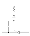
도 4, 도 5a, 도 5b를 참조하면, 제1 스위치 모듈 또는 제2 스위치 모듈은, 역 바이어스 다이오드(331, 341), TVS 다이오드(332, 342), 보호 저항(333, 343), 스위치 소자(334, 344), 커패시터(335, 345)를 포함할 수 있다Referring to FIGS. 4, 5A and 5B, the first switch module or the second switch module includes
역 바이어스 다이오드(331, 341)는 스위치 모듈이 오프(off) 상태인 경우, 반대 방향 전류를 차단하도록 한다. 예를 들어, 제1 입력단의 입력이 정상이고 제2 입력단의 입력이 오픈(open) 상태인 경우, 제2 스위치 모듈(340)의 상태는 오프(off)상태로 된다. 그런데, 제1 스위치 모듈의 상태는 온(on) 상태이므로, 과전압 보호 회로 또는 제어 모듈로부터 반대 방향 전류가 제1 입력단으로 역 바이어스 될 가능성이 존재한다. 따라서, 다이오드(331, 341)와 같은 소자를 적절하게 위치시켜, 역 바이어스 다이오드를 통하여 보다 더 안전한 램프를 구현할 수 있다.The
TVS 다이오드(332, 342)는 기 설정된 전압 이상이 인가되면 동작한다. 이 때, TVS 다이오드는 다이오드에 인가되는 전압이 54V 이상인 경우 동작하는 것을 특징으로 한다. 이러한 TVS 다이오드는, 고전압 과도에서 민감한 전자 기기를 보호하기 위하여 설계된 전자 부품으로, 과전압에서 보다 더 빠르게 응답할 수 있고, 정상적인 다이오드보다 더 큰 단면적을 가짐과 동시에 일정 수준에 전압을 제한함으로써 작동한다. 일반적으로는 정전기 방전 또는 데이터 라인과 연관되며, 조명 파업 및 유도성 부하 스위칭에 의해 유도되는 심한 압력을 방지하기 위해 사용될 수 있다.The
또한, TVS 다이오드는 정전기 방전(Electrostatic Discharge)이나 유도부하 스위칭 또는 유도방전에서 발생하는 전기적인 과도상태로부터 회로를 방지하기 위해 사용된다. TVS에서는, 회로의 손상을 주는 전압의 유입에 있어서, 이 전압의 크기를 회로가 손상되지 않을 정도로 감소시킨다. 또한, 과도현상이 발생되면, TVS는 즉시 제한전압(Clamping Voltage)을 기준으로 전압을 제한시킨다. In addition, the TVS diode is used to prevent circuitry from electrical transients that occur in electrostatic discharge, inductive load switching, or inductive discharges. In TVS, at the introduction of a voltage that causes damage to the circuit, the magnitude of this voltage is reduced to such an extent that the circuit is not damaged. In addition, when a transient occurs, the TVS immediately limits the voltage based on the Clamping Voltage.
보호 저항(333, 343)은 TVS 다이오드(332, 342)와 직렬로 연결되어, TVS 다이오드의 손상을 방지한다. 제1 입력단 또는 제2 입력단에 전원이 입력되는 경우, 순간적인 스파이크(spike) 전류가 통할 수 있는데, 보호 저항의 존재로 인하여 다이오드를 보호할 수 있다.The
스위치 소자(334, 344)는 기 설정된 조건에 따라 온(on)/오프(off) 할 수 있다. 이 때, 스위치 소자는, 스위치 소자에 인가되는 전압의 크기에 따라 온(on)/오프(off) 하는 것을 특징으로 한다. 이 때, 스위치 소자가 동작하는 상세한 설명은 도 6을 참조하기로 한다.The
또한, 스위치 소자는 사이리스터(SCR) 또는 FET인 것을 특징으로 하며, 전기적인 스위치 소자로 사용될 수 있는 모든 반도체 소자를 이용하여 구현할 수 있다. Further, the switching device is characterized by being a thyristor (SCR) or an FET, and can be implemented using all semiconductor devices that can be used as an electrical switching device.
도 5a를 참조하면, 본 발명의 누설전류 보호 회로를 구비한 안정기 호환형 램프는 사이리스터(SCR)로 구현될 수 있다. 사이리스터(thyristor; SRC)는 4층 반도체 소자이며, 실리콘 제어 정류기라고도 명칭된다. 이러한 사이리스터는 정류기의 한 종류이며, 게이트(Gate)로부터 음극(Cathode)에 게이트 전류를 흘려서, 양극(Anode)와 음극(Cathode) 사이를 도통할 수 있도록 한다. 게이트에 일정한 전류를 통과시키면, 양극과 음극간이 도통(스위치 온)하는 성질을 가지게 되며, 양극과 음극간의 전류를 일정치 이하로 낮추면 정지(스위치 오프)하게 된다. 따라서, 사이리스터는 무접점 온/오프 스위치로 동작할 수 있다.Referring to FIG. 5A, a ballast-compatible lamp having a leakage current protection circuit of the present invention may be implemented with a thyristor (SCR). A thyristor (SRC) is a four-layer semiconductor device, also called a silicon controlled rectifier. Such a thyristor is a kind of rectifier, and a gate current flows from a gate to a cathode so that a conduction can be made between an anode and a cathode. When a constant current is passed through the gate, the anode and the cathode are turned on (switched on). When the current between the anode and the cathode is lowered to a predetermined value or less, the cathode is stopped (switched off). Therefore, the thyristor can operate with a non-contact on / off switch.
이러한 사이리스터는, 고전압 대전류의 제어가 용이하며, 제어이득이 높고 게이트 신호가 소멸하여도 온 상태를 유지할 수 있다. 또한, 수명이 반영구적으로 신뢰성이 높으며, 써지 전압 전류에도 강하고, 소형/경량으로 기기나 장치에 있어서의 설치가 매우 용이한 장점이 있다.Such a thyristor can easily control a high voltage and a large current, can maintain an on state even when the control gain is high and the gate signal disappears. In addition, it is advantageous in that the life span is semi-permanently reliable, is strong against surge voltage current, and is small / light in weight and can be easily installed in a device or apparatus.
또한, 도 5a의 경우, 안정기 호환형 램프의 제1 스위치 모듈 또는 제2 스위치 모듈은, 사이리스터와 복수의 저항으로 이루어질 수도 있다. 그러나, 복수의 저항으로 이루어지는 경우, 제1 입력단으로부터 입력되는 입력 전원이 저항값에 따라서 전압 분배 또는 전류 분배의 용도로만 이용된다. 그러나, 본 발명과 같이 직렬로 연결되는 저항과 다이오드, 커패시터로 스위치 모듈을 구성하는 경우 별도의 전압 분배가 없이도 일정 전압 이상이면 곧바로 작동하며, 다이오드를 효과적으로 보호하고 신호의 노이즈를 제거할 수 있는 장점이 있다.In the case of Fig. 5A, the first switch module or the second switch module of the ballast-compatible lamp may be composed of a thyristor and a plurality of resistors. However, in the case of a plurality of resistors, the input power input from the first input terminal is used only for the purpose of voltage distribution or current distribution according to the resistance value. However, when a switch module is composed of a resistor, a diode, and a capacitor connected in series as in the present invention, the switch module operates immediately when the voltage is higher than a predetermined voltage without separate voltage distribution, effectively protecting the diode, .
도 5b를 참조하면, 본 발명의 누설전류 보호 회로를 구비한 안정기 호환형 램프는 전계 효과 트랜지스터(FET)로 구현될 수 있다. FET는 입력 임피던스가 매우 높은 특성을 가지며, 전압에 따라 구동된다. FET는 게이트(Gate)에 인가되는 전압의 크기에 따라서, 드레인(Drain)과 소스(Source) 간에 흐르는 전류가 크게 변화하게 된다. 따라서, FET 역시 게이트에 인가되는 전압의 크기에 따라서 온/오프 상태를 변화할 수 있으므로, 온/오프 스위치로 사용될 수 있다. Referring to FIG. 5B, the ballast-compatible lamp having the leakage current protection circuit of the present invention may be implemented as a field effect transistor (FET). FETs have very high input impedance and are driven by voltage. In the FET, the current flowing between the drain and the source changes largely depending on the magnitude of the voltage applied to the gate. Therefore, the FET can also be used as an on / off switch because the on / off state can be changed according to the magnitude of the voltage applied to the gate.
커패시터(335, 345)는 노이즈 필터링 역할을 수행한다. 제1 입력 전원 또는 제2 입력 전원에서 입력되는 전원에 존재하는 노이즈를 제거하기 위하여 커패시터를 위치시킬 수 있으며, 커패시터와 저항을 병렬로 연결한 R-C 필터를 사용할 수도 있다.The
과전압 보호 회로(350)는 상기 제1 스위치 모듈 및 상기 제2 스위치 모듈과 전기적으로 연결되어, 과전압을 방지한다. 이 때, 과전압 보호 회로는 안정기 호환 회로의 역할도 수행할 수 있다. 이는 안정기의 종류가 굉장히 많기 때문에, 안정기마다 다른 성능을 가질 수 있으므로, 서로 다른 안정기를 연결하는 경우 과전압이 인가될 수 있기 때문이다. 따라서, 과전압을 방지하고 회로를 보호하는 역할을 수행한다. The
또한, 상기 제1 스위치 모듈의 출력단과 상기 제2 스위치 모듈의 출력단은 전기적으로 연결되는 것을 특징으로 한다. 따라서, 제1 입력단과 제2 입력단 등 입력 단자에서는 각기 별개로 동작하다가, 과전압 보호 회로에 있어서 제1 스위치 모듈과 제2 스위치 모듈이 전기적으로 연결되기 때문에, 하나의 제어 모듈이 양 단에 위치하는 입력단과 스위치 모듈을 제어할 수 있다.The output terminal of the first switch module and the output terminal of the second switch module are electrically connected to each other. Therefore, since the first switch module and the second switch module are electrically connected to each other at the input terminals such as the first input terminal and the second input terminal in the overvoltage protection circuit, one control module is located at both ends The input stage and the switch module can be controlled.
제어 모듈(360)은 과전압 보호 회로와 전기적으로 연결되어, 상기 제1 스위치 모듈, 상기 제1 스위치 모듈, 상기 과전압 보호 회로의 상태를 감지하고 제어한다. The
광원(370)은 제어 모듈과 전기적으로 연결되어, 전원이 인가되면 빛을 조사한다. 이 때, 상기 광원은, LED인 것을 특징으로 한다.The
또한, 본 발명의 누설전류 보호 회로를 구비한 안정기 호환형 램프는, 제1 정류 회로(380) 또는 제2 정류 회로(390)를 더 포함할 수 있다. 제1 정류 회로(380)는 상기 제1 입력단으로부터 입력된 상기 제1 외부 전원을 정류하여 상기 제1 스위치 모듈에 인가하며, 제2 정류 회로(390)는 상기 제2 입력단으로부터 입력된 상기 제2 외부 전원을 정류하여 상기 제2 스위치 모듈에 인가한다. 이 때, 상기 제1 정류 회로 또는 상기 제2 정류 회로는, 브릿지 다이오드인 것을 특징으로 한다.In addition, the ballast-compatible lamp having the leakage current protection circuit of the present invention may further include a
또한, 본 발명의 누설전류 보호 회로를 구비한 안정기 호환형 램프는, 일단에 제1 입력단, 타단에 제2 입력단이 존재하는 직관형 램프인 것을 특징으로 한다. 또한, 상기 제1 입력단은, 제1 외부 전원을 입력받는 제1 입력 전극을 더 포함하고, 상기 제2 입력단은, 제2 외부 전원을 입력받는 제2 입력 전극을 더 포함하는 것을 특징으로 한다.In addition, the ballast-compatible lamp having the leakage current protection circuit of the present invention is an intrinsic lamp having a first input end at one end and a second input end at the other end. The first input terminal may further include a first input electrode receiving a first external power supply, and the second input terminal may further include a second input electrode receiving a second external power supply.
도 6은 본 발명의 일 실시예에 따른 누설전류 보호 회로를 구비한 안정기 호환형 램프가 과전압 상태에서 차단하게 되는 동작 방법을 나타내는 예시도이다.FIG. 6 is a diagram illustrating an exemplary operation of a ballast-compatible lamp having a leakage current protection circuit according to an exemplary embodiment of the present invention.
본 발명의 누설전류 보호 회로를 구비한 안정기 호환형 램프는, 상기 제1 외부 전원이 정상적으로 입력되고 상기 제2 외부 전원이 오픈(open) 상태인 경우, 상기 제1 스위치 모듈은 온(on) 상태이고 상기 제2 스위치 모듈은 오프(off) 상태인 것을 특징으로 한다. 또한, 상기 제1 외부 전원이 오픈(open) 상태이고 상기 제2 외부 전원이 정상적으로 입력되는 경우, 상기 제1 스위치 모듈은 오프(off) 상태이고 상기 제2 스위치 모듈은 온(on) 상태인 것을 특징으로 한다. In the ballast-compatible lamp having the leakage current protection circuit of the present invention, when the first external power is normally input and the second external power is in an open state, the first switch module is in an on state And the second switch module is in an off state. When the first external power is in an open state and the second external power is normally input, the first switch module is off and the second switch module is on .
이 때, 제1 외부 전원 또는 제2 외부 전원이 정상적으로 입력되는 상태란, 안정기와 접촉하여 입력되는 상태를 말하며, 제1 외부 전원 또는 제2 외부 전원이 오픈(open) 상태란, 안정기와 비 접촉 상태에서 입력되지 않는 상태를 말한다.The state where the first external power supply or the second external power supply is normally input refers to a state where the first external power supply or the second external power supply is in contact with the ballast, State that is not inputted in the state.
도 6을 참조하면, 본 발명의 제1 입력단이 제1 외부 전원과 연결된 상태이고, 제2 입력단은 제2 외부 전원과 연결되지 않은 오픈(open) 상태이다. 제1 외부 전원이 인가되기 때문에, 제1 정류 회로를 거쳐 제1 스위치 모듈이 온 상태로 된다. 그러나, 제2 스위치 모듈은 외부 전원이 인가되지 않았기 때문에 오프 상태를 유지하며, 제2 입력단(320) 쪽에 위치하는 사용자에게 누설 전류가 흘러가지 않도록 제2 스위치 모듈이 차단하게 된다. 마찬가지로, 제2 입력단이 제2 외부 전원과 연결된 상태이고, 제1 입력단 쪽을 사용자가 접촉하더라도, 제1 스위치 모듈이 오프 상태로 변화하므로 차단하게 된다.Referring to FIG. 6, the first input terminal of the present invention is connected to a first external power source, and the second input terminal is an open state not connected to a second external power source. Since the first external power supply is applied, the first switch module is turned on via the first rectifier circuit. However, the second switch module maintains the off state because the external power is not applied, and the second switch module blocks the leakage current to the user located on the
위에서 설명된 본 발명의 실시 예들은 예시의 목적을 위해 개시된 것이며, 이들에 의하여 본 발명이 한정되는 것은 아니다. 또한, 본 발명에 대한 기술 분야에서 통상의 지식을 가진 자라면 본 발명의 사상과 범위 안에서 다양한 수정 및 변경을 가할 수 있을 것이며, 이러한 수정 및 변경은 본 발명의 범위에 속하는 것으로 보아야 할 것이다.The embodiments of the present invention described above are disclosed for the purpose of illustration, and the present invention is not limited thereto. It will be apparent to those skilled in the art that various modifications and variations can be made in the present invention without departing from the spirit and scope of the invention.
210: 상용 전원
220: 안정기
230: 직관형 램프
231: 직관형 램프의 제1 전극
232: 직관형 램프의 제2 전극
240: 사용자
310: 제1 입력단
311: 제1 외부 전원
320: 제2 입력단
321: 제2 외부 전원
312, 322: 커패시터
330: 제1 스위치 모듈
340: 제2 스위치 모듈
331, 341: 역 바이어스 다이오드
332, 342: TVS 다이오드
333, 343: 보호 저항
334, 344: 스위치 소자
335, 345: 커패시터
350: 과전압 보호 회로
351: 저항
352: 사이리스터
353: 다이오드
354, 355: 커패시터
360: 제어 모듈
370: 광원
380: 제1 정류 회로
390: 제2 정류 회로210: Commercial Power 220: Ballast
230: straight tube lamp 231: first electrode of the straight tube lamp
232: second electrode of an intuitive lamp 240:
310: first input terminal 311: first external power supply
320: second input terminal 321: second external power source
312, 322: capacitor 330: first switch module
340: second switch module 331, 341: reverse bias diode
332, 342:
334, 344:
350: Overvoltage protection circuit 351: Resistance
352: Thyristor 353: Diode
354, 355: capacitor 360: control module
370: light source 380: first rectifier circuit
390: second rectifier circuit
Claims (14)
제2 외부 전원을 입력받는 제2 입력단;
상기 제1 입력단과 전기적으로 연결되어, 기 설정된 조건에 따라 스위치 온(on)/오프(off)하는 제1 스위치 모듈;
상기 제2 입력단과 전기적으로 연결되어, 기 설정된 조건에 따라 스위치 온(on)/오프(off)하는 제2 스위치 모듈;
상기 제1 스위치 모듈 및 상기 제2 스위치 모듈과 전기적으로 연결되어, 과전압을 방지하는 과전압 보호 회로;
상기 과전압 보호 회로와 전기적으로 연결되어, 상기 제1 스위치 모듈, 상기 제1 스위치 모듈, 상기 과전압 보호 회로의 상태를 감지하고 제어하는 제어 모듈;
상기 제어 모듈과 전기적으로 연결되어, 전원이 인가되면 빛을 조사하는 광원;
을 포함하는 누설전류 보호 회로를 구비한 안정기 호환형 램프.
A first input terminal receiving a first external power supply;
A second input terminal receiving a second external power supply;
A first switch module that is electrically connected to the first input terminal and switches on / off according to predetermined conditions;
A second switch module that is electrically connected to the second input terminal and turns on / off according to predetermined conditions;
An overvoltage protection circuit electrically connected to the first switch module and the second switch module to prevent an overvoltage;
A control module electrically connected to the overvoltage protection circuit to sense and control the states of the first switch module, the first switch module, and the overvoltage protection circuit;
A light source that is electrically connected to the control module and emits light when power is applied;
And a leakage current protection circuit including the leakage current protection circuit.
상기 제1 외부 전원 또는 상기 제2 외부 전원은,
상용 전원이 안정기에서 기 설정된 제1 외부 전원 및 제2 외부 전원으로 변환되어, 상기 제1 입력단 또는 상기 제2 입력단에 입력되는 것을 특징으로 하는 누설전류 보호 회로를 구비한 안정기 호환형 램프.
The method according to claim 1,
The first external power supply or the second external power supply,
Wherein the commercial power source is converted into a first external power source and a second external power source that are preset in the ballast, and is input to the first input terminal or the second input terminal.
상기 제1 입력단으로부터 입력된 상기 제1 외부 전원을 정류하여 상기 제1 스위치 모듈에 인가하는 제1 정류 회로;
상기 제2 입력단으로부터 입력된 상기 제2 외부 전원을 정류하여 상기 제2 스위치 모듈에 인가하는 제2 정류 회로;
를 더 포함하는 누설전류 보호 회로를 구비한 안정기 호환형 램프.
The method according to claim 1,
A first rectifying circuit rectifying the first external power inputted from the first input terminal and applying the rectified first external power to the first switch module;
A second rectifying circuit rectifying the second external power inputted from the second input terminal and applying the rectified second external power to the second switch module;
Further comprising a leakage current protection circuit that further includes a leakage current protection circuit.
상기 제1 정류 회로 또는 상기 제2 정류 회로는,
브릿지 다이오드인 것을 특징으로 하는 누설전류 보호 회로를 구비한 안정기 호환형 램프.
The method of claim 3,
Wherein the first rectifying circuit or the second rectifying circuit comprises:
Wherein the lamp is a bridge diode.
상기 제1 스위치 모듈 또는 상기 제2 스위치 모듈은,
스위치 모듈이 오프(off) 상태인 경우, 반대 방향 전류를 차단하는 역 바이어스 다이오드;
기 설정된 전압 이상이 인가되면 동작하는 TVS 다이오드;
상기 TVS 다이오드의 손상을 방지하는 보호 저항;
기 설정된 조건에 따라 온(on)/오프(off) 하는 스위치 소자;
노이즈 필터링 역할을 수행하는 커패시터;
를 포함하는 것을 특징으로 하는 누설전류 보호 회로를 구비한 안정기 호환형 램프.
The method according to claim 1,
Wherein the first switch module or the second switch module includes:
A reverse bias diode for blocking the reverse current when the switch module is off;
A TVS diode operating when a predetermined voltage or more is applied;
A protection resistor to prevent damage to the TVS diode;
A switch element that turns on / off in accordance with predetermined conditions;
A capacitor performing a noise filtering function;
Wherein the lamp is a light source.
상기 스위치 소자는,
사이리스터(SCR) 또는 FET인 것을 특징으로 하는 누설전류 보호 회로를 구비한 안정기 호환형 램프.
6. The method of claim 5,
The switch element includes:
Characterized in that the lamp is a thyristor (SCR) or a FET.
상기 스위치 소자는,
스위치 소자에 인가되는 전압의 크기에 따라 온(on)/오프(off) 하는 것을 특징으로 하는 누설전류 보호 회로를 구비한 안정기 호환형 램프.
6. The method of claim 5,
The switch element includes:
Wherein the switch is turned on / off according to a magnitude of a voltage applied to the switch element.
상기 TVS 다이오드는,
다이오드에 인가되는 전압이 54V 이상인 경우 동작하는 것을 특징으로 하는 누설전류 보호 회로를 구비한 안정기 호환형 램프.
6. The method of claim 5,
The TVS diode includes:
Wherein the diode is operated when the voltage applied to the diode is greater than or equal to 54V.
상기 제1 스위치 모듈의 출력단과 상기 제2 스위치 모듈의 출력단은 전기적으로 연결되는 것을 특징으로 하는 누설전류 보호 회로를 구비한 안정기 호환형 램프.
The method according to claim 1,
Wherein the output terminal of the first switch module and the output terminal of the second switch module are electrically connected to each other.
상기 제1 외부 전원이 정상적으로 입력되고 상기 제2 외부 전원이 오픈(open) 상태인 경우, 상기 제1 스위치 모듈은 온(on) 상태이고 상기 제2 스위치 모듈은 오프(off) 상태인 것을 특징으로 하는 누설전류 보호 회로를 구비한 안정기 호환형 램프.
The method according to claim 1,
The first switch module is on and the second switch module is off when the first external power is normally input and the second external power is open. A ballast compatible lamp with a leakage current protection circuit.
상기 제1 외부 전원이 오픈(open) 상태이고 상기 제2 외부 전원이 정상적으로 입력되는 경우, 상기 제1 스위치 모듈은 오프(off) 상태이고 상기 제2 스위치 모듈은 온(on) 상태인 것을 특징으로 하는 누설전류 보호 회로를 구비한 안정기 호환형 램프.
The method according to claim 1,
The first switch module is off and the second switch module is on when the first external power is in an open state and the second external power is normally input, A ballast compatible lamp with a leakage current protection circuit.
상기 광원은,
LED인 것을 특징으로 하는 누설전류 보호 회로를 구비한 안정기 호환형 램프.
The method according to claim 1,
The light source includes:
Wherein the lamp is an LED.
상기 안정기 호환형 램프는,
일단에 제1 입력단, 타단에 제2 입력단이 존재하는 직관형 램프인 것을 특징으로 하는 누설전류 보호 회로를 구비한 안정기 호환형 램프.
The method according to claim 1,
The ballast-
Wherein the lamp is an intrinsic lamp having a first input end at one end and a second input end at the other end.
상기 제1 입력단은, 제1 외부 전원을 입력받는 제1 입력 전극을 더 포함하고, 상기 제2 입력단은, 제2 외부 전원을 입력받는 제2 입력 전극을 더 포함하는 것을 특징으로 하는 누설전류 보호 회로를 구비한 안정기 호환형 램프.The method according to claim 1,
Wherein the first input terminal further comprises a first input electrode for receiving a first external power supply and the second input terminal further comprises a second input electrode for receiving a second external power supply, A ballast compatible lamp with circuitry.
Priority Applications (4)
| Application Number | Priority Date | Filing Date | Title |
|---|---|---|---|
| KR1020150129707A KR20170032003A (en) | 2015-09-14 | 2015-09-14 | Ballast stabilizer compatible Lamp with a leakage-current protection circuit |
| JP2016178249A JP2017059531A (en) | 2015-09-14 | 2016-09-13 | Ballast stabilizer-compatible lamp having leakage current protection circuit |
| US15/263,541 US9839081B2 (en) | 2015-09-14 | 2016-09-13 | Ballast stabilizer-compatible lamp having leakage current protection circuit |
| CN201610827523.2A CN106851890A (en) | 2015-09-14 | 2016-09-14 | The compatible lamp of ballast stabilizer with leakage current protection circuit |
Applications Claiming Priority (1)
| Application Number | Priority Date | Filing Date | Title |
|---|---|---|---|
| KR1020150129707A KR20170032003A (en) | 2015-09-14 | 2015-09-14 | Ballast stabilizer compatible Lamp with a leakage-current protection circuit |
Publications (1)
| Publication Number | Publication Date |
|---|---|
| KR20170032003A true KR20170032003A (en) | 2017-03-22 |
Family
ID=58257727
Family Applications (1)
| Application Number | Title | Priority Date | Filing Date |
|---|---|---|---|
| KR1020150129707A KR20170032003A (en) | 2015-09-14 | 2015-09-14 | Ballast stabilizer compatible Lamp with a leakage-current protection circuit |
Country Status (4)
| Country | Link |
|---|---|
| US (1) | US9839081B2 (en) |
| JP (1) | JP2017059531A (en) |
| KR (1) | KR20170032003A (en) |
| CN (1) | CN106851890A (en) |
Cited By (2)
| Publication number | Priority date | Publication date | Assignee | Title |
|---|---|---|---|---|
| WO2020009268A1 (en) * | 2018-07-04 | 2020-01-09 | 주식회사엘디티 | Electronic ballast-compatible light emitting diode driving circuit |
| KR20230173888A (en) | 2022-06-20 | 2023-12-27 | 현대모비스 주식회사 | Reverse voltage prevention circuit with redundant power structure |
Families Citing this family (14)
| Publication number | Priority date | Publication date | Assignee | Title |
|---|---|---|---|---|
| US11131431B2 (en) | 2014-09-28 | 2021-09-28 | Jiaxing Super Lighting Electric Appliance Co., Ltd | LED tube lamp |
| CN205979248U (en) | 2014-09-28 | 2017-02-22 | 嘉兴山蒲照明电器有限公司 | LED (Light -emitting diode) straight lamp |
| US10208898B2 (en) * | 2015-04-29 | 2019-02-19 | Jiaxing Super Lighting Electric Appliance Co., Ltd. | LED tube lamp with operating modes compatible with electrical ballasts |
| US10560989B2 (en) | 2014-09-28 | 2020-02-11 | Jiaxing Super Lighting Electric Appliance Co., Ltd | LED tube lamp |
| US9897265B2 (en) | 2015-03-10 | 2018-02-20 | Jiaxing Super Lighting Electric Appliance Co., Ltd. | LED tube lamp having LED light strip |
| US11519565B2 (en) | 2015-03-10 | 2022-12-06 | Jiaxing Super Lighting Electric Appliance Co., Ltd | LED lamp and its power source module |
| US11028973B2 (en) | 2015-03-10 | 2021-06-08 | Jiaxing Super Lighting Electric Appliance Co., Ltd. | Led tube lamp |
| US11035526B2 (en) | 2015-12-09 | 2021-06-15 | Jiaxing Super Lighting Electric Appliance Co., Ltd. | LED tube lamp |
| CN106922053B (en) * | 2017-03-23 | 2019-03-12 | 东莞泛美光电有限公司 | The LED drive circuit of controllable leakage current |
| CN207283866U (en) * | 2017-07-18 | 2018-04-27 | 晨辉光宝科技有限公司 | LED straight lamps |
| CN109561541B (en) * | 2017-09-27 | 2021-12-28 | 朗德万斯公司 | Dual function lamp driver |
| CN108631800B (en) * | 2018-05-09 | 2020-11-27 | 深圳市盛路物联通讯技术有限公司 | Low-power-consumption radio frequency circuit and terminal of Internet of things |
| KR200488187Y1 (en) * | 2018-11-05 | 2018-12-24 | 조헌구 | Universal LED Light |
| CN111542147A (en) * | 2020-06-01 | 2020-08-14 | 厦门普为光电科技有限公司 | Lamp tube with electric shock protection and compatible electronic ballast and power frequency AC power supply |
Family Cites Families (3)
| Publication number | Priority date | Publication date | Assignee | Title |
|---|---|---|---|---|
| US9163818B2 (en) * | 2012-06-15 | 2015-10-20 | Lightel Technologies, Inc. | Linear solid-state lighting with degenerate voltage sensing free of fire and shock hazards |
| US9277603B2 (en) * | 2013-12-19 | 2016-03-01 | Lightel Technologies, Inc. | Linear solid-state lighting with frequency sensing free of fire and shock hazards |
| KR101534785B1 (en) * | 2014-05-30 | 2015-07-08 | 주식회사 아모센스 | Led lamp using over voltage protection circuit |
-
2015
- 2015-09-14 KR KR1020150129707A patent/KR20170032003A/en unknown
-
2016
- 2016-09-13 JP JP2016178249A patent/JP2017059531A/en active Pending
- 2016-09-13 US US15/263,541 patent/US9839081B2/en not_active Expired - Fee Related
- 2016-09-14 CN CN201610827523.2A patent/CN106851890A/en active Pending
Cited By (3)
| Publication number | Priority date | Publication date | Assignee | Title |
|---|---|---|---|---|
| WO2020009268A1 (en) * | 2018-07-04 | 2020-01-09 | 주식회사엘디티 | Electronic ballast-compatible light emitting diode driving circuit |
| KR20200004515A (en) * | 2018-07-04 | 2020-01-14 | 주식회사엘디티 | Driving circuit for electronic ballast compatible led |
| KR20230173888A (en) | 2022-06-20 | 2023-12-27 | 현대모비스 주식회사 | Reverse voltage prevention circuit with redundant power structure |
Also Published As
| Publication number | Publication date |
|---|---|
| CN106851890A (en) | 2017-06-13 |
| US9839081B2 (en) | 2017-12-05 |
| JP2017059531A (en) | 2017-03-23 |
| US20170079100A1 (en) | 2017-03-16 |
Similar Documents
| Publication | Publication Date | Title |
|---|---|---|
| KR20170032003A (en) | Ballast stabilizer compatible Lamp with a leakage-current protection circuit | |
| KR20170037345A (en) | AC Direct Drive Lamp with a leakage-current protection circuit | |
| US8284536B2 (en) | Surge protection module for luminaires and lighting control devices | |
| US6816350B1 (en) | AC voltage protection circuit | |
| US10566785B2 (en) | Surge protective device with abnormal overvoltage protection | |
| US10004123B1 (en) | Failure detection and alerting circuit for a differential mode surge protection device in an LED driver | |
| US20150326003A1 (en) | Earth Leakage Circuit Breaker | |
| TW200638807A (en) | Load failure protection circuit and discharge lamp driving apparatus | |
| KR101572670B1 (en) | Street light control system having a function of preventing the breakage of the led due to such a leakage current and electric surge voltage | |
| CN102204406A (en) | Circuit arrangement and method for operating an oled | |
| KR101326004B1 (en) | Illuminator having a protection circuit | |
| JP5126241B2 (en) | Overvoltage protection circuit and overvoltage protection method | |
| US9913346B1 (en) | Surge protection system and method for an LED driver | |
| US20140071572A1 (en) | Surge protection device | |
| KR200474702Y1 (en) | Apparatus for driving light emitting diode lamps | |
| JP6703577B2 (en) | Power supply protector | |
| CN108306275B (en) | Power supply protection circuit and electronic equipment | |
| US10320181B1 (en) | Failure detection and alerting circuit for a common mode surge protection device in an LED driver | |
| US11677235B2 (en) | Avalanche triggered overvoltage protection | |
| KR100478762B1 (en) | Apparatus for displaying and detecting an overvoltage and leakage current | |
| KR20130073236A (en) | Surge protection devices | |
| CA2518021C (en) | Self-contained, self-snubbed, hid dimming module that exhibits non-zero crossing detection switching | |
| KR100745835B1 (en) | Leakage current sensor type power off device | |
| JP2017103156A (en) | Protective device for power supply unit and circuit device | |
| KR20160071546A (en) | Lighting apparatus using pn junction light emitting means |